PIC Basic Hardware Structure

Welcome message from author
This document is posted to help you gain knowledge. Please leave a comment to let me know what you think about it! Share it to your friends and learn new things together.
Transcript

8/10/2019 PIC Part4 HardwareSetup
http://slidepdf.com/reader/full/pic-part4-hardwaresetup 1/52
PIC Basic Hardware Structure

8/10/2019 PIC Part4 HardwareSetup
http://slidepdf.com/reader/full/pic-part4-hardwaresetup 2/52
CpE 112 : Klinkhachorn
PIC16F877

8/10/2019 PIC Part4 HardwareSetup
http://slidepdf.com/reader/full/pic-part4-hardwaresetup 3/52
CpE 112 : Klinkhachorn
PIC16F877 (Cont.)

8/10/2019 PIC Part4 HardwareSetup
http://slidepdf.com/reader/full/pic-part4-hardwaresetup 4/52CpE 112 : Klinkhachorn
CLOCK
✔PIC needs a clock to operate the chip.
✔Each instruction cycle requires 4 clock
cycles
– 20MHz clock (50ns clock) ---> 200ns
instruction cycle
✔PIC is fully static (DC-20MHz) – The processor clock can be completely stopped
• SLEEP instruction shuts down the clock oscillator!
– saving power (draw just a few microamperes)
8/10/2019 PIC Part4 HardwareSetup
http://slidepdf.com/reader/full/pic-part4-hardwaresetup 5/52CpE 112 : Klinkhachorn
Clock Oscillator Configurations
✔Four different oscillator modes can be used
with the PIC16F877
– RC - Resistor/capacitor
– XT - crystal or ceramic resonator
– HS - high speed crystal or ceramic resonator
– LP - low power crystal✔ The user must program two configuration bits
(FOSC1 and FOSC0) to select one of the four!

8/10/2019 PIC Part4 HardwareSetup
http://slidepdf.com/reader/full/pic-part4-hardwaresetup 6/52CpE 112 : Klinkhachorn
Clock Oscillator: RC✔ RC mode is simple and inexpensive if application
is not at all timing sensitive
– The external capacitor can be eliminated, but Microchip warns that the
frequency can vary widely and change often. They recommend at least
20pF of external capacitance for anything resembling stable operation.
8/10/2019 PIC Part4 HardwareSetup
http://slidepdf.com/reader/full/pic-part4-hardwaresetup 7/52CpE 112 : Klinkhachorn
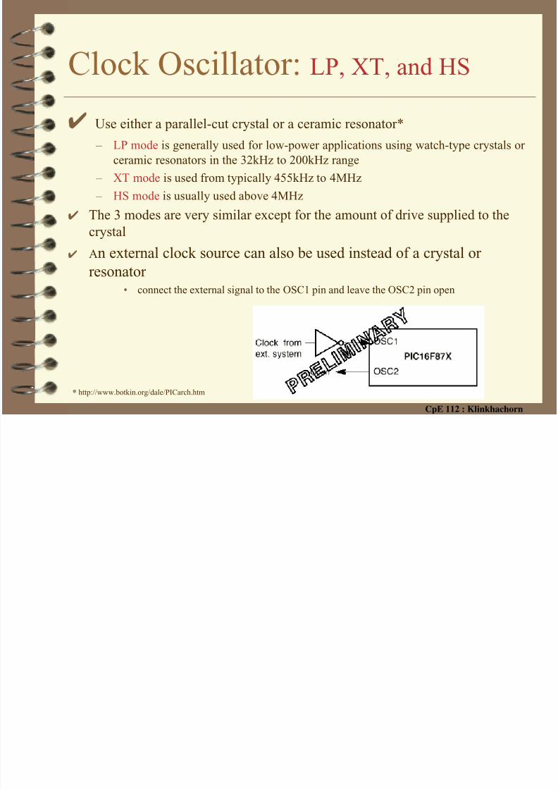
Clock Oscillator: LP, XT, and HS
✔ Use either a parallel-cut crystal or a ceramic resonator*
– LP mode is generally used for low-power applications using watch-type crystals orceramic resonators in the 32kHz to 200kHz range
– XT mode is used from typically 455kHz to 4MHz
– HS mode is usually used above 4MHz
✔ The 3 modes are very similar except for the amount of drive supplied to thecrystal
✔ An external clock source can also be used instead of a crystal or
resonator
• connect the external signal to the OSC1 pin and leave the OSC2 pin open
* http://www.botkin.org/dale/PICarch.htm
8/10/2019 PIC Part4 HardwareSetup
http://slidepdf.com/reader/full/pic-part4-hardwaresetup 8/52CpE 112 : Klinkhachorn
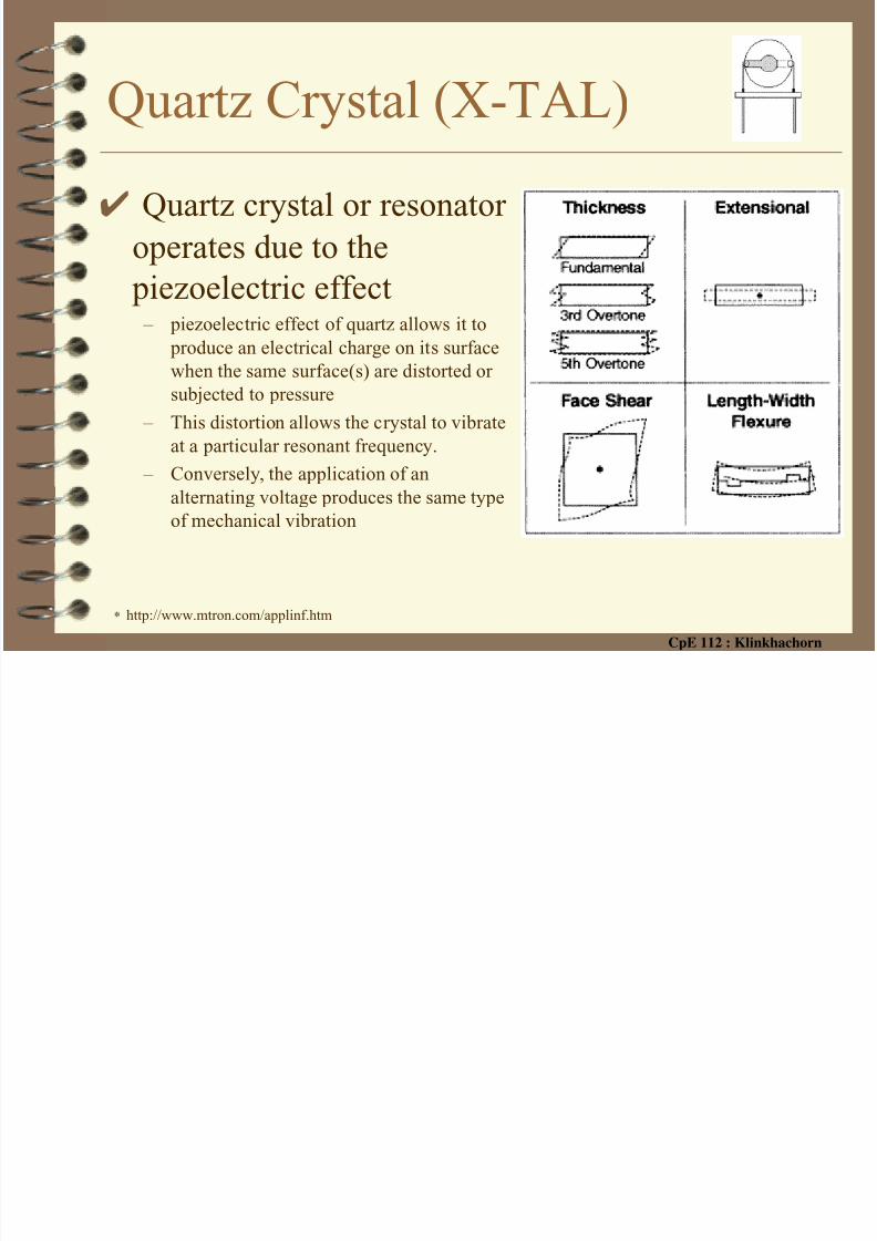
Quartz Crystal (X-TAL)
✔ Quartz crystal or resonator
operates due to the
piezoelectric effect – piezoelectric effect of quartz allows it to
produce an electrical charge on its surfacewhen the same surface(s) are distorted or
subjected to pressure
– This distortion allows the crystal to vibrate
at a particular resonant frequency.
– Conversely, the application of an
alternating voltage produces the same type
of mechanical vibration
* http://www.mtron.com/applinf.htm
8/10/2019 PIC Part4 HardwareSetup
http://slidepdf.com/reader/full/pic-part4-hardwaresetup 9/52CpE 112 : Klinkhachorn
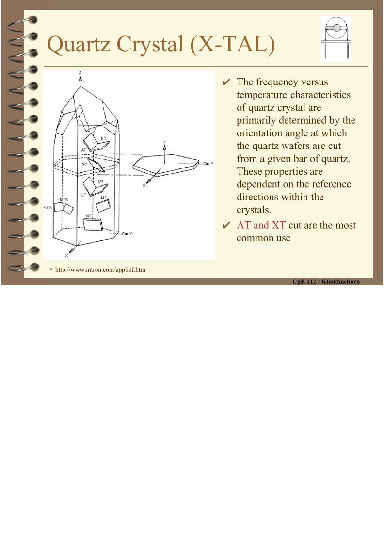
Quartz Crystal (X-TAL)✔ The frequency versus
temperature characteristics
of quartz crystal are
primarily determined by the
orientation angle at which
the quartz wafers are cut
from a given bar of quartz.
These properties are
dependent on the reference
directions within thecrystals.
✔ AT and XT cut are the most
common use
* http://www.mtron.com/applinf.htm

8/10/2019 PIC Part4 HardwareSetup
http://slidepdf.com/reader/full/pic-part4-hardwaresetup 10/52CpE 112 : Klinkhachorn
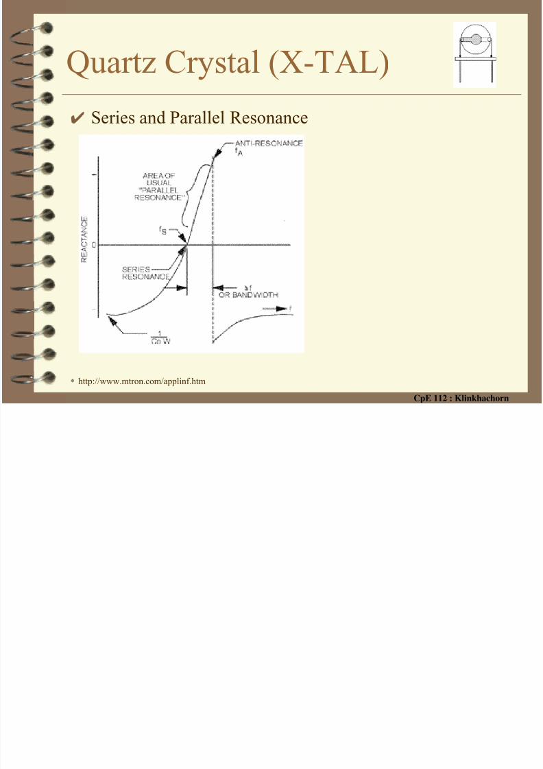
Quartz Crystal (X-TAL)✔X-tal equivalent circuit
✔Very High Q (the higher the "Q" the smaller the
bandwidth and the steeper the reactance curve)* http://www.mtron.com/applinf.htm
8/10/2019 PIC Part4 HardwareSetup
http://slidepdf.com/reader/full/pic-part4-hardwaresetup 11/52CpE 112 : Klinkhachorn
Quartz Crystal (X-TAL)✔ Series and Parallel Resonance
* http://www.mtron.com/applinf.htm

8/10/2019 PIC Part4 HardwareSetup
http://slidepdf.com/reader/full/pic-part4-hardwaresetup 12/52CpE 112 : Klinkhachorn
Quartz Crystal OSCillator ✔ Typical Pierce Oscillator circuit
• use fundamental mode x-tal• the inverter is biased into a linear mode
by feedback resistor R F
• inverter stage will provide a 1800 phase
shift between its input and output• the crystal and the two capacitors
provide additional1800 phase allowing
for in-phase energy to be applied to the
input of the inverter stage (completes thefeedback loop)
• oscillation can occur as long as the
inverter can provide a voltage gain that
is greater than 1
* http://www.mtron.com/applinf.htm

8/10/2019 PIC Part4 HardwareSetup
http://slidepdf.com/reader/full/pic-part4-hardwaresetup 13/52CpE 112 : Klinkhachorn
Clock Oscillator: LP, XT, and HS
✔ When using a crystal or resonator, it is good practice to connect a
small capacitor from each OSC lead to ground. This helps assurestable oscillator operation and reliable start-up.
* http://www.botkin.org/dale/PICarch.htm

8/10/2019 PIC Part4 HardwareSetup
http://slidepdf.com/reader/full/pic-part4-hardwaresetup 14/52
CpE 112 : Klinkhachorn
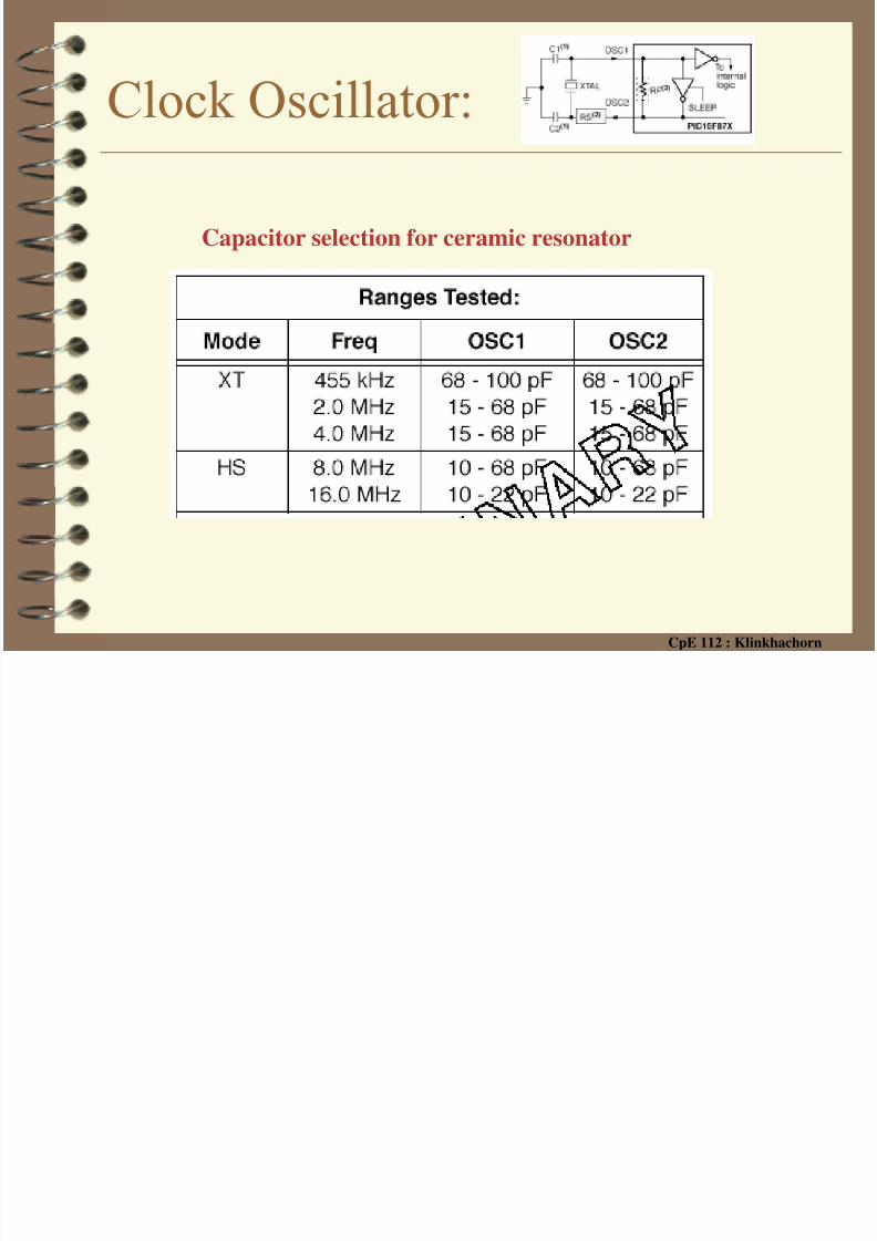
Clock Oscillator:
Capacitor selection for X-tal Osc.
8/10/2019 PIC Part4 HardwareSetup
http://slidepdf.com/reader/full/pic-part4-hardwaresetup 15/52
CpE 112 : Klinkhachorn
Clock Oscillator:
Capacitor selection for ceramic resonator
8/10/2019 PIC Part4 HardwareSetup
http://slidepdf.com/reader/full/pic-part4-hardwaresetup 16/52
CpE 112 : Klinkhachorn
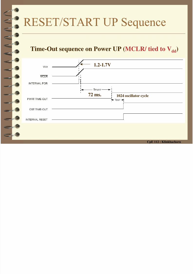
RESET/START UP Sequence
Time-Out sequence on Power UP (MCLR/ tied to Vdd)
72 ms. 1024 oscillator cycle
1.2-1.7V

8/10/2019 PIC Part4 HardwareSetup
http://slidepdf.com/reader/full/pic-part4-hardwaresetup 17/52
CpE 112 : Klinkhachorn
RESET/START UP✔ Power-On Reset (POR)
– Pulse is generated on-chip when VDD rise is detected (1.2-1.7V) – MCLR/ must be tie directly (or through a resistor) to VDD
✔ MCLR/ reset during normal operation/sleep
• External reset switch can be added to regain control if needed
PICMCLR/
Vdd
1 0 K 1 0 0
RESET

8/10/2019 PIC Part4 HardwareSetup
http://slidepdf.com/reader/full/pic-part4-hardwaresetup 18/52
CpE 112 : Klinkhachorn
RESET/START UP✔ Brown-Out Reset (BOR)
– If Vdd falls below VBOR (about 4 volts) for longer than TBOR
(100us), the brown out circuit will reset the device
• Device will remain in brown-out reset until Vdd rises above VBOR then
the normal start up sequence begins
– Can be enabled/disable through configuration bit , BODEN
✔ Watch Dog Timer Reset & Wakeup

8/10/2019 PIC Part4 HardwareSetup
http://slidepdf.com/reader/full/pic-part4-hardwaresetup 19/52
CpE 112 : Klinkhachorn
RESETSimplified Block Diagram of On-Chip Reset Circuit

8/10/2019 PIC Part4 HardwareSetup
http://slidepdf.com/reader/full/pic-part4-hardwaresetup 20/52
CpE 112 : Klinkhachorn
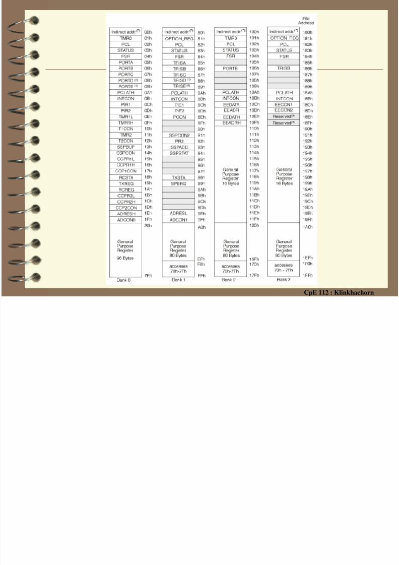
Digital Input/Output PortsSpecial Register File MAP for 16F877 Digital I/O ports
I/O Ports Control Ports (direction registers)
8/10/2019 PIC Part4 HardwareSetup
http://slidepdf.com/reader/full/pic-part4-hardwaresetup 21/52
CpE 112 : Klinkhachorn
Input/Output Ports✔ Some pins for these I/O ports are multiplexed with an
alternate function for the peripheral features on thedevice
– Examples
• A/D inputs, Timer input, …..✔ When a peripheral is enabled, that pin may not be used
as a general purpose I/O pin
✔Some I/O pins may have – Schmitt Trigger input and an open drain output
– TTL input levels and full CMOS output drivers.
8/10/2019 PIC Part4 HardwareSetup
http://slidepdf.com/reader/full/pic-part4-hardwaresetup 22/52
CpE 112 : Klinkhachorn
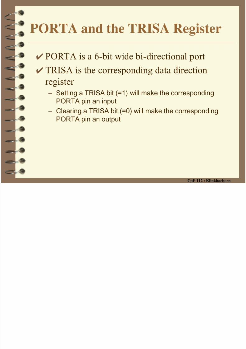
PORTA and the TRISA Register
✔ PORTA is a 6-bit wide bi-directional port
✔ TRISA is the corresponding data direction
register – Setting a TRISA bit (=1) will make the corresponding
PORTA pin an input
– Clearing a TRISA bit (=0) will make the corresponding
PORTA pin an output

8/10/2019 PIC Part4 HardwareSetup
http://slidepdf.com/reader/full/pic-part4-hardwaresetup 23/52
CpE 112 : Klinkhachorn
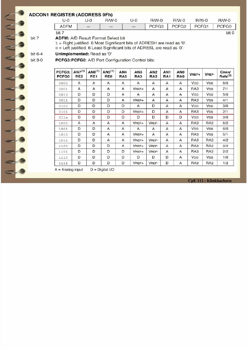
PORTA special function pins

8/10/2019 PIC Part4 HardwareSetup
http://slidepdf.com/reader/full/pic-part4-hardwaresetup 24/52
CpE 112 : Klinkhachorn
PORTA
RA3:RA0 AND RA5 PINS

8/10/2019 PIC Part4 HardwareSetup
http://slidepdf.com/reader/full/pic-part4-hardwaresetup 25/52
CpE 112 : Klinkhachorn
PORTA
RA4/ T0CKI PIN

8/10/2019 PIC Part4 HardwareSetup
http://slidepdf.com/reader/full/pic-part4-hardwaresetup 26/52
8/10/2019 PIC Part4 HardwareSetup
http://slidepdf.com/reader/full/pic-part4-hardwaresetup 27/52
CpE 112 : Klinkhachorn
8/10/2019 PIC Part4 HardwareSetup
http://slidepdf.com/reader/full/pic-part4-hardwaresetup 28/52
CpE 112 : Klinkhachorn
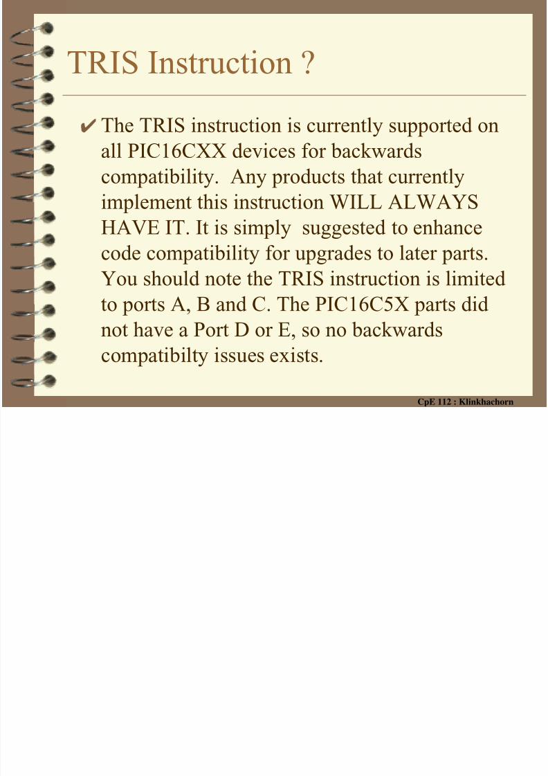
TRIS Instruction ?✔ The TRIS instruction is currently supported on
all PIC16CXX devices for backwardscompatibility. Any products that currently
implement this instruction WILL ALWAYS
HAVE IT. It is simply suggested to enhance
code compatibility for upgrades to later parts.
You should note the TRIS instruction is limited
to ports A, B and C. The PIC16C5X parts did
not have a Port D or E, so no backwards
compatibilty issues exists.

8/10/2019 PIC Part4 HardwareSetup
http://slidepdf.com/reader/full/pic-part4-hardwaresetup 29/52
CpE 112 : Klinkhachorn
TRIS Instruction ?

8/10/2019 PIC Part4 HardwareSetup
http://slidepdf.com/reader/full/pic-part4-hardwaresetup 30/52
CpE 112 : Klinkhachorn
PORTB and the TRISB Register
✔ PORTB is an 8-bit wide, bi-directional port
– Each of the PORTB pins also has a weak internal pull-up (programmable)
✔ TRISB is the corresponding data direction
register – Setting a TRISB bit (=1) will make the corresponding
PORTB pin an input
– Clearing a TRISB bit (=0) will make the correspondingPORTB pin an output
8/10/2019 PIC Part4 HardwareSetup
http://slidepdf.com/reader/full/pic-part4-hardwaresetup 31/52
CpE 112 : Klinkhachorn
PORTB Weak internal pull-up
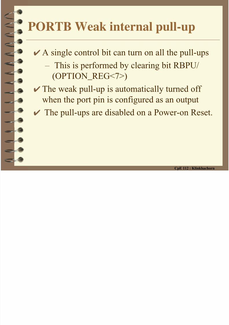
✔A single control bit can turn on all the pull-ups
– This is performed by clearing bit RBPU/
(OPTION_REG<7>)
✔The weak pull-up is automatically turned offwhen the port pin is configured as an output
✔ The pull-ups are disabled on a Power-on Reset.
8/10/2019 PIC Part4 HardwareSetup
http://slidepdf.com/reader/full/pic-part4-hardwaresetup 32/52
CpE 112 : Klinkhachorn
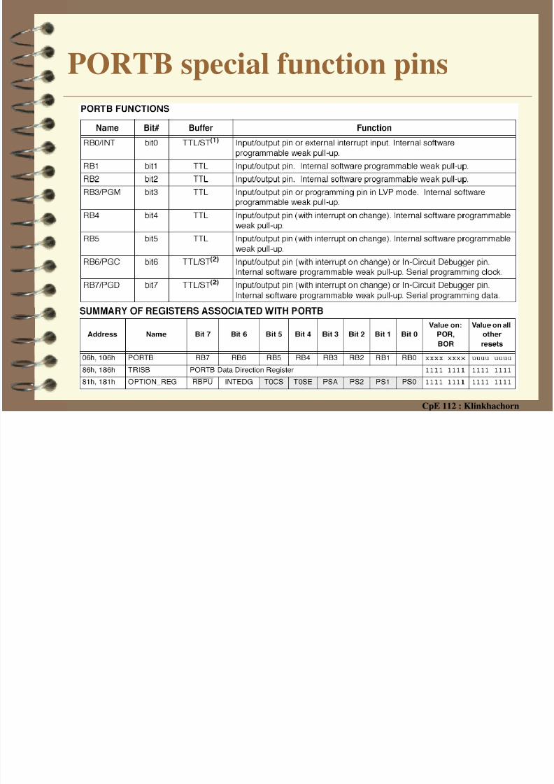
PORTB special function pins

8/10/2019 PIC Part4 HardwareSetup
http://slidepdf.com/reader/full/pic-part4-hardwaresetup 33/52
CpE 112 : Klinkhachorn
PORTBRB0:RB3

8/10/2019 PIC Part4 HardwareSetup
http://slidepdf.com/reader/full/pic-part4-hardwaresetup 34/52
CpE 112 : Klinkhachorn
PORTBRB4:RB7
8/10/2019 PIC Part4 HardwareSetup
http://slidepdf.com/reader/full/pic-part4-hardwaresetup 35/52
CpE 112 : Klinkhachorn

8/10/2019 PIC Part4 HardwareSetup
http://slidepdf.com/reader/full/pic-part4-hardwaresetup 36/52
CpE 112 : Klinkhachorn
PORTC and the TRISC Register✔ PORTC is an 8-bit wide, bi-directional port
– Each of the PORTC pins has a Totem pole outputdriver
✔ TRISC is the corresponding data direction
register – Setting a TRISC bit (=1) will make the corresponding
PORTC pin an input
– Clearing a TRISC bit (=0) will make the corresponding
PORTC pin an output
8/10/2019 PIC Part4 HardwareSetup
http://slidepdf.com/reader/full/pic-part4-hardwaresetup 37/52
CpE 112 : Klinkhachorn
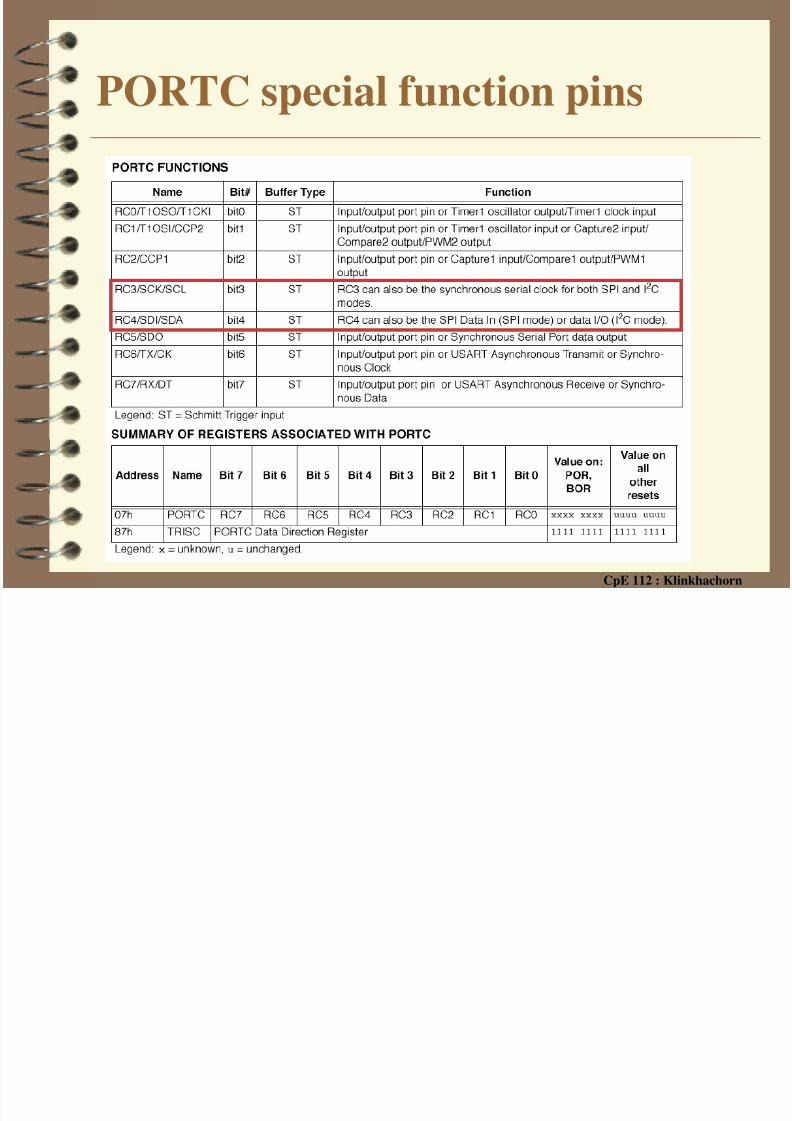
PORTC special function pins

8/10/2019 PIC Part4 HardwareSetup
http://slidepdf.com/reader/full/pic-part4-hardwaresetup 38/52
CpE 112 : Klinkhachorn
PORTCRC<0:2>, <5:7>
8/10/2019 PIC Part4 HardwareSetup
http://slidepdf.com/reader/full/pic-part4-hardwaresetup 39/52
CpE 112 : Klinkhachorn
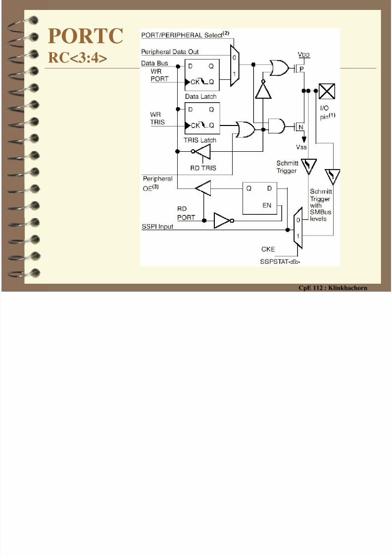
PORTCRC<3:4>

8/10/2019 PIC Part4 HardwareSetup
http://slidepdf.com/reader/full/pic-part4-hardwaresetup 40/52
CpE 112 : Klinkhachorn
PORTD and the TRISD Register✔ PORTD is an 8-bit wide, bi-directional port
– Each of the PORTC pins has a Totem pole output
driver and Schmitt Trigger input buffers
✔ PORTD can be configured as an 8-bit wide
microprocessor port ( parallel slave port) by
setting control bit
✔ not applicable to the PIC16F873 or PIC16F876✔ TRISD is the corresponding data direction register
– Setting a TRISD bit (=1) will make the corresponding PORTD pin an
input
– Clearing a TRISD bit (=0) will make the corresponding PORTD pin anoutput

8/10/2019 PIC Part4 HardwareSetup
http://slidepdf.com/reader/full/pic-part4-hardwaresetup 41/52
CpE 112 : Klinkhachorn
PORTD special function pins
8/10/2019 PIC Part4 HardwareSetup
http://slidepdf.com/reader/full/pic-part4-hardwaresetup 42/52
CpE 112 : Klinkhachorn
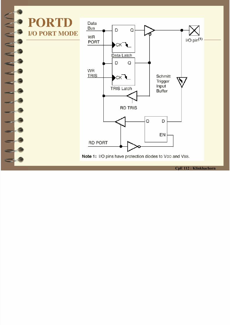
PORTDI/O PORT MODE
8/10/2019 PIC Part4 HardwareSetup
http://slidepdf.com/reader/full/pic-part4-hardwaresetup 43/52
CpE 112 : Klinkhachorn
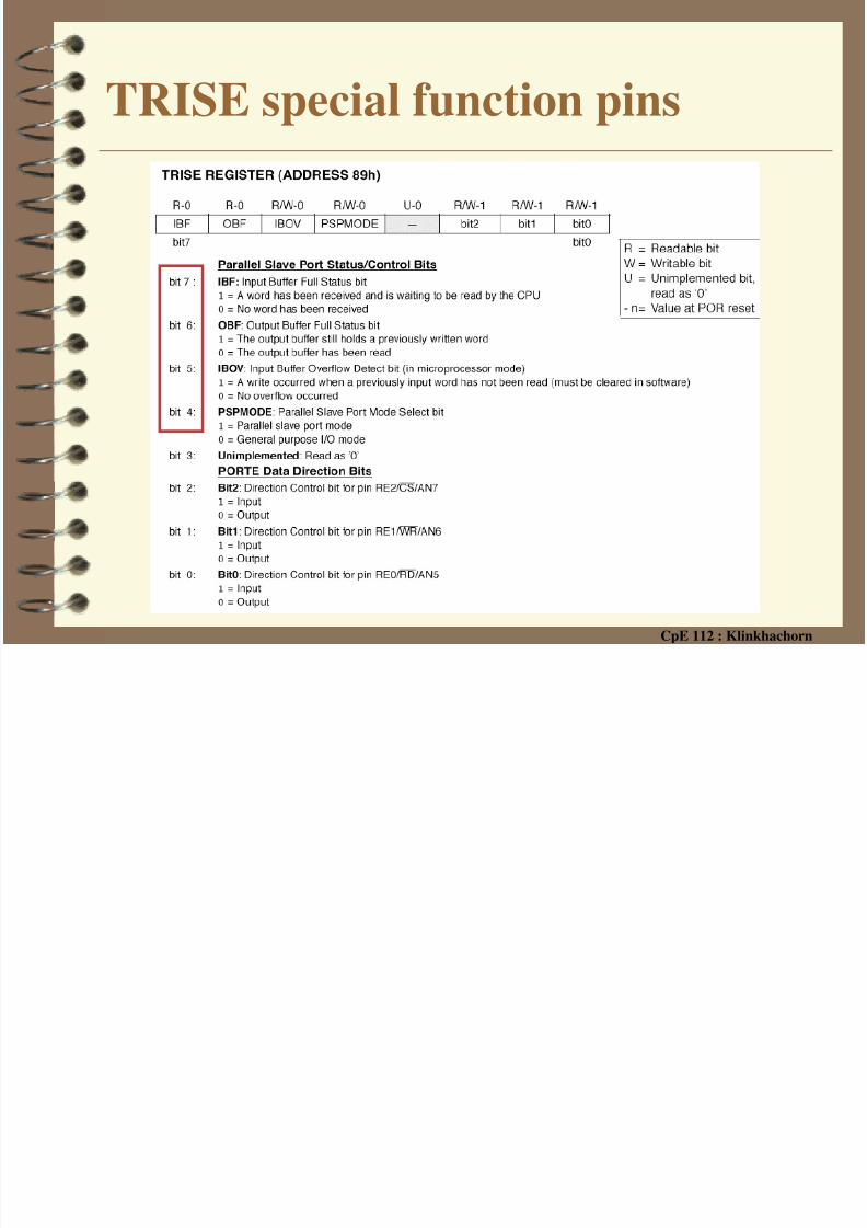
PORTE and the TRISE Register✔ PORTE has three pins, RE0/RD/AN5,
RE1/WR/AN6 and RE2/CS/AN7, which areindividually configurable as inputs or outputs
– these pins have Schmitt Trigger input buffers.
✔ not applicable to the PIC16F873 or PIC16F876✔ TRISE is the corresponding data direction register
– Setting a TRISE bit (=1) will make the corresponding PORTD pin an
input – Clearing a TRISE bit (=0) will make the corresponding PORTD pin an
output

8/10/2019 PIC Part4 HardwareSetup
http://slidepdf.com/reader/full/pic-part4-hardwaresetup 44/52
CpE 112 : Klinkhachorn
PORTE special function pins
PORTE

8/10/2019 PIC Part4 HardwareSetup
http://slidepdf.com/reader/full/pic-part4-hardwaresetup 45/52
CpE 112 : Klinkhachorn
PORTEI/O PORT MODE

8/10/2019 PIC Part4 HardwareSetup
http://slidepdf.com/reader/full/pic-part4-hardwaresetup 46/52
CpE 112 : Klinkhachorn
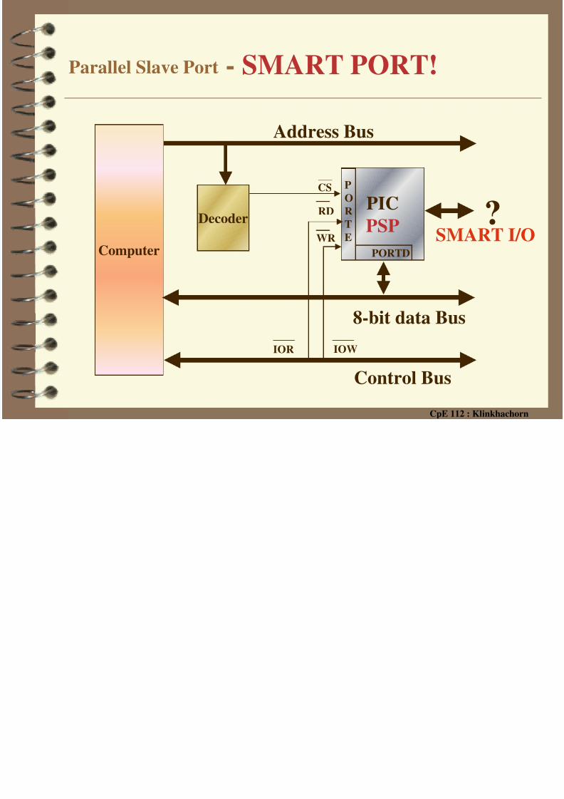
PORTE - Parallel Slave Port control lines
✔ I/O PORTE becomes control inputs for the
microprocessor port when bit PSPMODE(TRISE<4>) is set
– the user must make sure that the TRISE<2:0> bits are
set (pins are configured as digital inputs)
– ensure ADCON1 is configured for digital I/O.
– PORTD operates as an 8-bit wide Parallel Slave Port
or microprocessor port
• In slave mode, it is asynchronously readable and writable by
the external world through RD control input pin RE0/RD
and WR control input pin RE1/WR
8/10/2019 PIC Part4 HardwareSetup
http://slidepdf.com/reader/full/pic-part4-hardwaresetup 47/52
CpE 112 : Klinkhachorn
TRISE special function pins
PORTE

8/10/2019 PIC Part4 HardwareSetup
http://slidepdf.com/reader/full/pic-part4-hardwaresetup 48/52
CpE 112 : Klinkhachorn
PORTEParallel Slave Port
PORTD & PORTE

8/10/2019 PIC Part4 HardwareSetup
http://slidepdf.com/reader/full/pic-part4-hardwaresetup 49/52
CpE 112 : Klinkhachorn
PORTD & PORTEParallel Slave Port - WRITE CYCLE
PORTD & PORTE

8/10/2019 PIC Part4 HardwareSetup
http://slidepdf.com/reader/full/pic-part4-hardwaresetup 50/52
CpE 112 : Klinkhachorn
PORTD & PORTEParallel Slave Port - READ CYCLE
8/10/2019 PIC Part4 HardwareSetup
http://slidepdf.com/reader/full/pic-part4-hardwaresetup 51/52
CpE 112 : Klinkhachorn
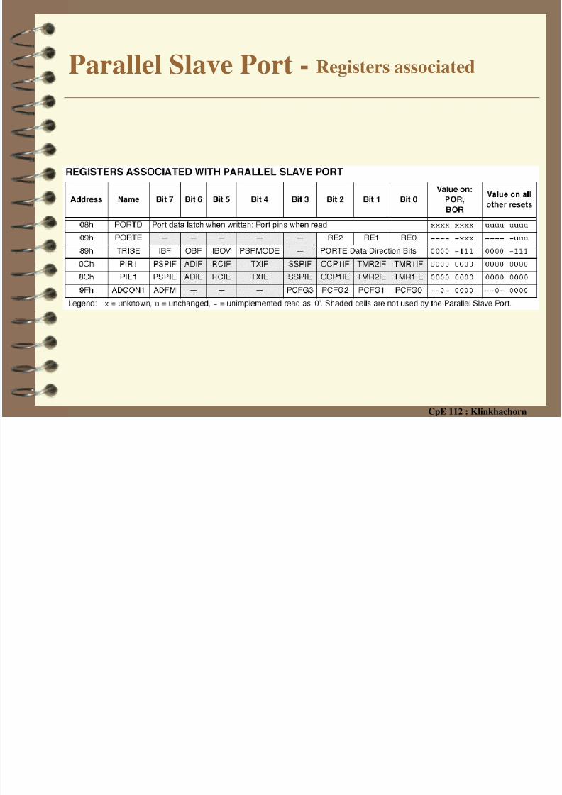
Parallel Slave Port - Registers associated
8/10/2019 PIC Part4 HardwareSetup
http://slidepdf.com/reader/full/pic-part4-hardwaresetup 52/52
Related Documents