Book: PIC Microcontrollers - Programming in C Chapter 1: World of Microcontrollers The situation we find ourselves today in the field of microcontrollers has its beginnings in the development of technology of integrated circuits. It enabled us to store hundreds of thousands of transistors into one chip, which was a precondition for the manufacture of microprocessors. The first computers were made by adding external peripherals, such as memory, input/output lines, timers and other circuits, to it. Further increasing of package density resulted in designing an integrated circuit which contained both processor and peripherals. This is how the first chip containing a microcomputer later known as the microcontroller was developed. • 1.1 Introduction • 1.2 NUMBERS, NUMBERS, NUMBERS... • 1.3 MUST KNOW DETAILS • 1.4 PIC MICROCONTROLLERS 1.1 INTRODUCTION Novices in electronics usually think that the microcontroller is the same as the microprocessor. That’s not true. They differ from each other in many ways. The first and most important difference in favour of the microcontroller is its functionality. In order that the microprocessor may be used, other components, memory comes first, must be added to it. Even though it is considered a powerful computing machine, it is not adjusted to communicating to peripheral environment. In order to enable the microprocessor to communicate with peripheral environment, special circuits must be used. This is how it was in the beginning and remains the same today. www.raguvaran.puzl.com

Welcome message from author
This document is posted to help you gain knowledge. Please leave a comment to let me know what you think about it! Share it to your friends and learn new things together.
Transcript
Book: PIC Microcontrollers - Programming in C
Chapter 1: World of Microcontrollers
The situation we find ourselves today in the field of microcontrollers has its beginnings in the
development of technology of integrated circuits. It enabled us to store hundreds of thousands of
transistors into one chip, which was a precondition for the manufacture of microprocessors. The
first computers were made by adding external peripherals, such as memory, input/output lines,
timers and other circuits, to it. Further increasing of package density resulted in designing an
integrated circuit which contained both processor and peripherals. This is how the first chip
containing a microcomputer later known as the microcontroller was developed.
• 1.1 Introduction • 1.2 NUMBERS, NUMBERS, NUMBERS... • 1.3 MUST KNOW DETAILS • 1.4 PIC MICROCONTROLLERS
1.1 INTRODUCTION
Novices in electronics usually think that the microcontroller is the same as the microprocessor.
That’s not true. They differ from each other in many ways. The first and most important difference
in favour of the microcontroller is its functionality. In order that the microprocessor may be used,
other components, memory comes first, must be added to it. Even though it is considered a
powerful computing machine, it is not adjusted to communicating to peripheral environment. In
order to enable the microprocessor to communicate with peripheral environment, special circuits
must be used. This is how it was in the beginning and remains the same today.
www.raguvaran.puzl.com

On the other hand, the microcontroller is designed to be all of that in one. No other specialized
external components are needed for its application because all necessary circuits which
otherwise belong to peripherals are already built in it. It saves time and space needed to design a
device.
ALL THE MICROCONTROLLER CAN DO
In order to make it easier for you to understand the reasons for such a great success of
microcontrollers, we will call your attention for a few minutes to the following example.
About ten years ago, designing of an electronic device controlling the elevator in a multistory
building was enormously difficult, even for a team of experts. Have you ever thought about what
requirements an ordinary elevator must meet? How to deal with the situation when two or more
people call the elevator at the same time? Which call has priority? How to handle security
question? Loss of electricity? Failure? Misuse?...What comes after solving these basic questions
is a painstaking process of designing appropriate electronics using a large number of specialized
chips. Depending on device complexity, this process can take weeks or months. When finished,
its time to design a printed circuit board and assemble device. A huge device! It is another long-
lasting and trying work. Finally, when everything is finished and tested for many times, the crucial
moment comes when you concentrate, take a deep breath and switch the power supply on.
This is usually the point at which the party turns into a real work since electronic devices almost
never starts to operate immediately. Get ready for many sleepless nights, corrections,
improvements... and don’t forget, we are still talking about running an ordinary elevator.
www.raguvaran.puzl.com

When your device finally starts to operate perfectly and everybody is satisfied and you finally get
paid for the work you have done, many constructing companies will become interested in your
work. Of course, if you are lucky, another day will bring you a locking offer from a new investor.
However, a new building has four stories more. You know what it is about? You think you can
control destiny? You are going to make a universal device which can be used in buildings of 4 to
40 stories, a masterpiece of electronics? All right, even if you manage to make such an electronic
jewel, your investor will wait in front of your door asking for a camera in elevator. Or for relaxing
music in the event of the failure of elevator. Or for two-door elevator. Anyway, Murphy’s law is
inexorable and you will certainly not be able to make an advantage of all the effort you have
made. Unfortunately, everything that has been said now is true. This is what ‘handling electronics’
really means. No, wait, let us correct ourself, that is how it was until the first microcontrollers were
designed - small, powerful and cheap microcontrollers. Since the moment their programming
stopped being a science, everything took another direction...
Electronics capable of controlling a small submarine, a crane or the above mentioned elevator is
now built in one single chip. Microcontrollers offer a wide range of applications and only some of
them are normally used. It’s up to you to decide what you want the microcontroller to do and
dump a program containing appropriate instructions into it. Prior to turning on the device, its
operation should be tested by a simulator. If everything works fine, build the microcontroller into
your device. If you ever need to change, improve or upgrade the program, just do it. Until when?
Until you feel satisfied. That’s all.
www.raguvaran.puzl.com

www.raguvaran.puzl.com
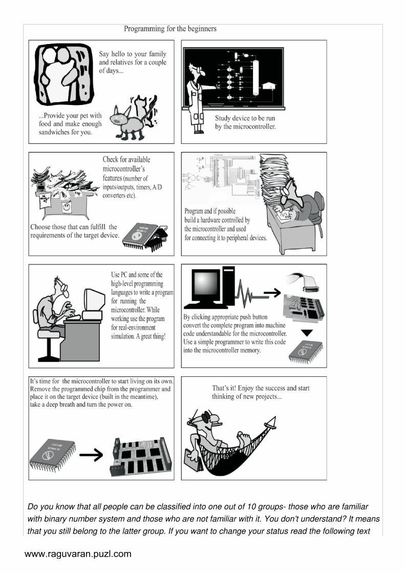
Do you know that all people can be classified into one out of 10 groups- those who are familiar
with binary number system and those who are not familiar with it. You don’t understand? It means
that you still belong to the latter group. If you want to change your status read the following text
www.raguvaran.puzl.com
describing briefly some of the basic concepts used further in this book (just to be sure we are on
the same page).
1.2 NUMBERS, NUMBERS, NUMBERS...
Mathematics is such a good science! Everything is so logical... The whole universe can be
described with ten digits only. But, does it really have to be like that? Do we need exactly ten
digits? Of course not, it is only a matter of habit. Remember the lessons from the school. For
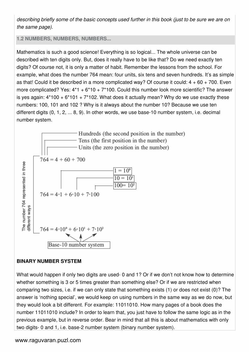
example, what does the number 764 mean: four units, six tens and seven hundreds. It’s as simple
as that! Could it be described in a more complicated way? Of course it could: 4 + 60 + 700. Even
more complicated? Yes: 4*1 + 6*10 + 7*100. Could this number look more scientific? The answer
is yes again: 4*100 + 6*101 + 7*102. What does it actually mean? Why do we use exactly these
numbers: 100, 101 and 102 ? Why is it always about the number 10? Because we use ten
different digits (0, 1, 2, ... 8, 9). In other words, we use base-10 number system, i.e. decimal
number system.
BINARY NUMBER SYSTEM
What would happen if only two digits are used- 0 and 1? Or if we don’t not know how to determine
whether something is 3 or 5 times greater than something else? Or if we are restricted when
comparing two sizes, i.e. if we can only state that something exists (1) or does not exist (0)? The
answer is ‘nothing special’, we would keep on using numbers in the same way as we do now, but
they would look a bit different. For example: 11011010. How many pages of a book does the
number 11011010 include? In order to learn that, you just have to follow the same logic as in the
previous example, but in reverse order. Bear in mind that all this is about mathematics with only
two digits- 0 and 1, i.e. base-2 number system (binary number system).
www.raguvaran.puzl.com

It is obviously the same number represented in two different number systems. The only difference
between these two representations is the number of digits necessary for writing a number. One
digit (2) is used to write the number 2 in decimal system, whereas two digits (1 and 0) are used to
write it in binary system. Do you now agree that there are 10 groups of people? Welcome to the
world of binary arithmetic! Do you have any idea where it is used?
Except for strictly controlled laboratory conditions, the most complicated electronic circuits cannot
accurately determine the difference between two sizes (two voltage values, for example) if they
are too small (lower than several volts). The reasons are electrical noises and something called
the ‘real working environment’ (unpredictable changes of power supply voltage, temperature
changes, tolerance to values of built-in components etc.). Imagine a computer which operates
upon decimal numbers by treating them in the following way: 0=0V, 1=5V, 2=10V, 3=15V,
4=20V...9=45V.
Did anybody say batteries?
A far simpler solution is a binary logic where 0 indicates that there is no voltage and 1 indicates
that there is a voltage. It is easier to write 0 or 1 instead of full sentences ‘there is no voltage’ or
‘there is voltage’, respectively. It is about logic zero (0) and logic one (1) which electronics
perfectly cope with and easily performs all those endlessly complex mathematical operations.
Obviously, the electronics we are talking about applies mathematics in which all the numbers are
represented by two digits only and where it is only important to know whether there is a voltage or
not. Of course, we are talking about digital electronics.
HEXADECIMAL NUMBER SYSTEM
At the very beginning of computer development it was realized that people had many difficulties in
handling binary numbers. For this reason, a new number system, using 16 different symbols was
established. It is called hexadecimal number system and consists of the ten digits we are used to
(0, 1, 2, 3,... 9) and six letters of alphabet A, B, C, D, E and F. You probably wonder about the
purpose of this seemingly bizarre combination? Just look how perfectly it fits the story about
binary numbers and you will understand.
www.raguvaran.puzl.com
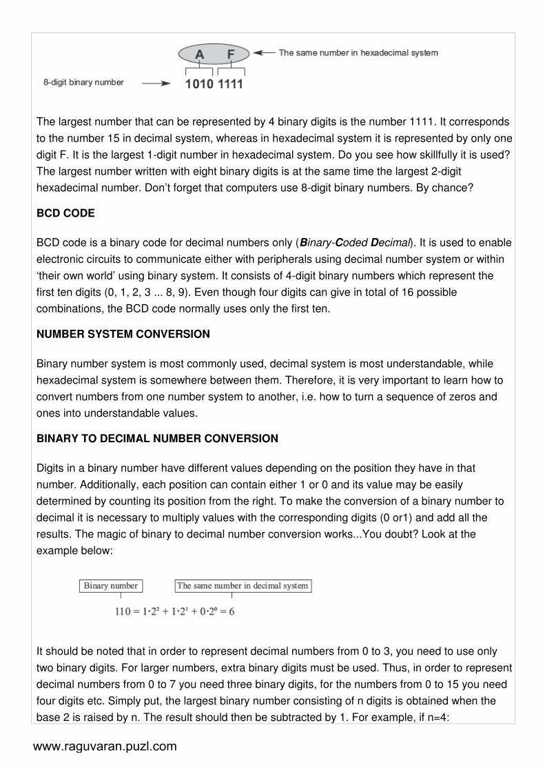
The largest number that can be represented by 4 binary digits is the number 1111. It corresponds
to the number 15 in decimal system, whereas in hexadecimal system it is represented by only one
digit F. It is the largest 1-digit number in hexadecimal system. Do you see how skillfully it is used?
The largest number written with eight binary digits is at the same time the largest 2-digit
hexadecimal number. Don’t forget that computers use 8-digit binary numbers. By chance?
BCD CODE
BCD code is a binary code for decimal numbers only (Binary-Coded Decimal). It is used to enable
electronic circuits to communicate either with peripherals using decimal number system or within
‘their own world’ using binary system. It consists of 4-digit binary numbers which represent the
first ten digits (0, 1, 2, 3 ... 8, 9). Even though four digits can give in total of 16 possible
combinations, the BCD code normally uses only the first ten.
NUMBER SYSTEM CONVERSION
Binary number system is most commonly used, decimal system is most understandable, while
hexadecimal system is somewhere between them. Therefore, it is very important to learn how to
convert numbers from one number system to another, i.e. how to turn a sequence of zeros and
ones into understandable values.
BINARY TO DECIMAL NUMBER CONVERSION
Digits in a binary number have different values depending on the position they have in that
number. Additionally, each position can contain either 1 or 0 and its value may be easily
determined by counting its position from the right. To make the conversion of a binary number to
decimal it is necessary to multiply values with the corresponding digits (0 or1) and add all the
results. The magic of binary to decimal number conversion works...You doubt? Look at the
example below:
It should be noted that in order to represent decimal numbers from 0 to 3, you need to use only
two binary digits. For larger numbers, extra binary digits must be used. Thus, in order to represent
decimal numbers from 0 to 7 you need three binary digits, for the numbers from 0 to 15 you need
four digits etc. Simply put, the largest binary number consisting of n digits is obtained when the
base 2 is raised by n. The result should then be subtracted by 1. For example, if n=4:
www.raguvaran.puzl.com
24 - 1 = 16 - 1 = 15
Accordingly, by using 4 binary digits it is possible to represent decimal numbers from 0 to 15,
which amounts to 16 different values in total.
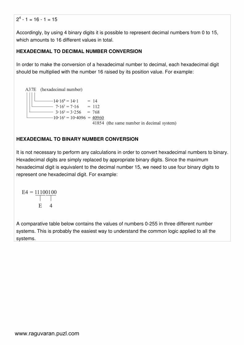
HEXADECIMAL TO DECIMAL NUMBER CONVERSION
In order to make the conversion of a hexadecimal number to decimal, each hexadecimal digit
should be multiplied with the number 16 raised by its position value. For example:
HEXADECIMAL TO BINARY NUMBER CONVERSION
It is not necessary to perform any calculations in order to convert hexadecimal numbers to binary.
Hexadecimal digits are simply replaced by appropriate binary digits. Since the maximum
hexadecimal digit is equivalent to the decimal number 15, we need to use four binary digits to
represent one hexadecimal digit. For example:
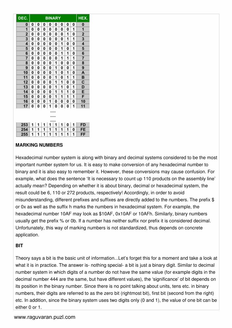
A comparative table below contains the values of numbers 0-255 in three different number
systems. This is probably the easiest way to understand the common logic applied to all the
systems.
www.raguvaran.puzl.com
MARKING NUMBERS
Hexadecimal number system is along with binary and decimal systems considered to be the most
important number system for us. It is easy to make conversion of any hexadecimal number to
binary and it is also easy to remember it. However, these conversions may cause confusion. For
example, what does the sentence ‘It is necessary to count up 110 products on the assembly line’
actually mean? Depending on whether it is about binary, decimal or hexadecimal system, the
result could be 6, 110 or 272 products, respectively! Accordingly, in order to avoid
misunderstanding, different prefixes and suffixes are directly added to the numbers. The prefix $
or 0x as well as the suffix h marks the numbers in hexadecimal system. For example, the
hexadecimal number 10AF may look as $10AF, 0x10AF or 10AFh. Similarly, binary numbers
usually get the prefix % or 0b. If a number has neither suffix nor prefix it is considered decimal.
Unfortunately, this way of marking numbers is not standardized, thus depends on concrete
application.
BIT
Theory says a bit is the basic unit of information...Let’s forget this for a moment and take a look at
what it is in practice. The answer is- nothing special- a bit is just a binary digit. Similar to decimal
number system in which digits of a number do not have the same value (for example digits in the
decimal number 444 are the same, but have different values), the ‘significance’ of bit depends on
its position in the binary number. Since there is no point talking about units, tens etc. in binary
numbers, their digits are referred to as the zero bit (rightmost bit), first bit (second from the right)
etc. In addition, since the binary system uses two digits only (0 and 1), the value of one bit can be
either 0 or 1.
www.raguvaran.puzl.com
Don’t be confused if you come across a bit having value 4, 16 or 64. It just means that its value is
represented in decimal system. Simply put, we have got so much accustomed to the usage of
decimal numbers that such expressions became common. It would be correct to say for example,
‘the value of the sixth bit of any binary number is equivalent to the decimal number 64’. But we
are human and old habits die hard...Besides, how would it sound ‘number one-one-zeroone-
zero...’?
BYTE
A byte consists of eight bits grouped together. If a bit is a digit, it is logical that bytes represent
numbers. All mathematical operations can be performed upon them, like upon common decimal
numbers. Similar to digits of any number, byte digits do not have the same significance either.
The greatest value has the leftmost bit called the most significant bit (MSB). The rightmost bit has
the least value and is therefore called the least significant bit (LSB). Since eight zeros and ones of
one byte can be combined in 256 different ways, the largest decimal number which can be
represented by one byte is 255 (one combination represents a zero).
A nibble is referred to as half a byte. Depending on which half of the register we are talking about
(left or right), there are ‘high’ and ‘low’ nibbles, respectively.
Have you ever wondered what electronics within digital integrated circuits, microcontrollers or
processors look like? What do circuits performing complicated mathematical operations and
making decisions look like? Do you know that their seemingly complicated schematic comprise
only a few different elements called logic circuits or logic gates?
1.3 MUST KNOW DETAILS
The operation of these elements is based on principles established by a British mathematician
George Boole in the middle of the 19th century- even before the first bulb was invented.
Originally, the main idea was to express logical forms through algebraic functions. Such thinking
was soon transformed into a practical product which far later evaluated in what today is known as
AND, OR and NOT logic circuits. The principle of their operation is known as Boolean algebra.
LOGIC CIRCUITS
Some of the program instructions give the same results as logic gates. The principle of their
operation will be discussed in the text below.
www.raguvaran.puzl.com
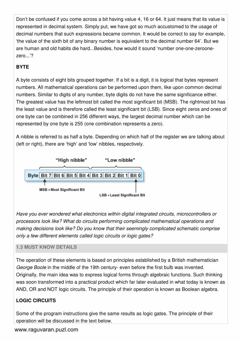
AND Gate
The logic gate ‘AND’ has two or more inputs and one output. Let us presume that the gate used in
this example has only two inputs. A logic one (1) will appear on its output only if both inputs (A
AND B) are driven high (1). Table on the right shows mutual dependence between inputs and the
output.
When used in a program, a logic AND operation is performed by the program instruction, which
will be discussed later. For the time being, it is enough to remember that logic AND in a program
refers to the corresponding bits of two registers.
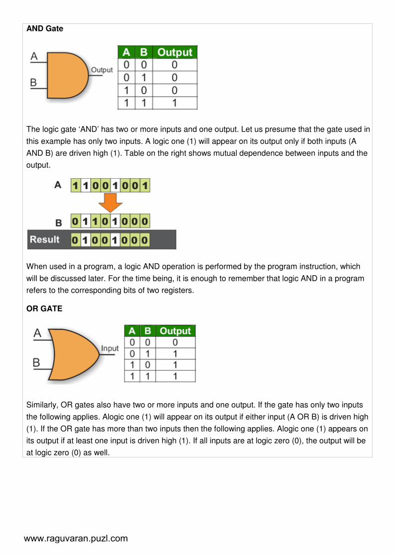
OR GATE
Similarly, OR gates also have two or more inputs and one output. If the gate has only two inputs
the following applies. Alogic one (1) will appear on its output if either input (A OR B) is driven high
(1). If the OR gate has more than two inputs then the following applies. Alogic one (1) appears on
its output if at least one input is driven high (1). If all inputs are at logic zero (0), the output will be
at logic zero (0) as well.
www.raguvaran.puzl.com
In the program, logic OR operation is performed in the same manner as logic AND operation.
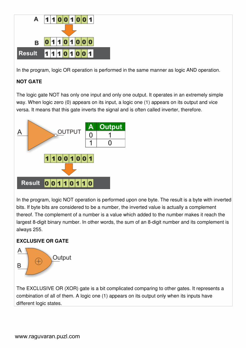
NOT GATE
The logic gate NOT has only one input and only one output. It operates in an extremely simple
way. When logic zero (0) appears on its input, a logic one (1) appears on its output and vice
versa. It means that this gate inverts the signal and is often called inverter, therefore.
In the program, logic NOT operation is performed upon one byte. The result is a byte with inverted
bits. If byte bits are considered to be a number, the inverted value is actually a complement
thereof. The complement of a number is a value which added to the number makes it reach the
largest 8-digit binary number. In other words, the sum of an 8-digit number and its complement is
always 255.
EXCLUSIVE OR GATE
The EXCLUSIVE OR (XOR) gate is a bit complicated comparing to other gates. It represents a
combination of all of them. A logic one (1) appears on its output only when its inputs have
different logic states.
www.raguvaran.puzl.com
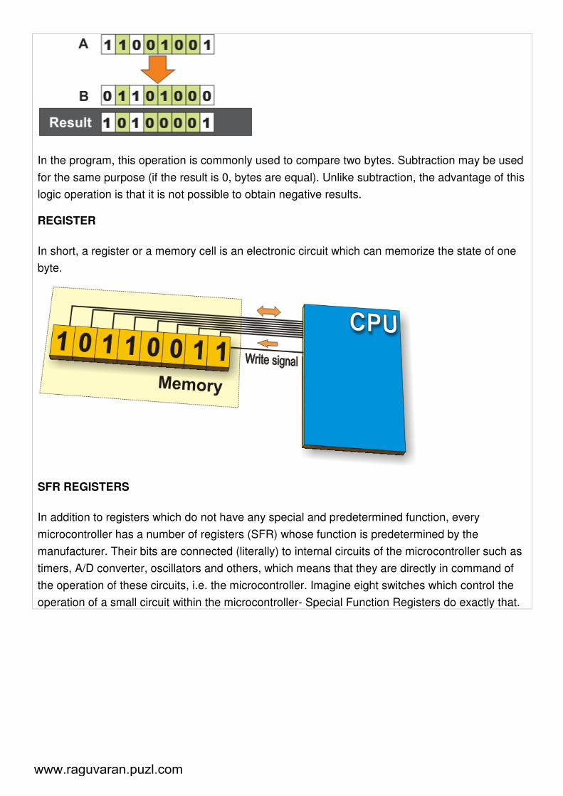
In the program, this operation is commonly used to compare two bytes. Subtraction may be used
for the same purpose (if the result is 0, bytes are equal). Unlike subtraction, the advantage of this
logic operation is that it is not possible to obtain negative results.
REGISTER
In short, a register or a memory cell is an electronic circuit which can memorize the state of one
byte.
SFR REGISTERS
In addition to registers which do not have any special and predetermined function, every
microcontroller has a number of registers (SFR) whose function is predetermined by the
manufacturer. Their bits are connected (literally) to internal circuits of the microcontroller such as
timers, A/D converter, oscillators and others, which means that they are directly in command of
the operation of these circuits, i.e. the microcontroller. Imagine eight switches which control the
operation of a small circuit within the microcontroller- Special Function Registers do exactly that.
www.raguvaran.puzl.com
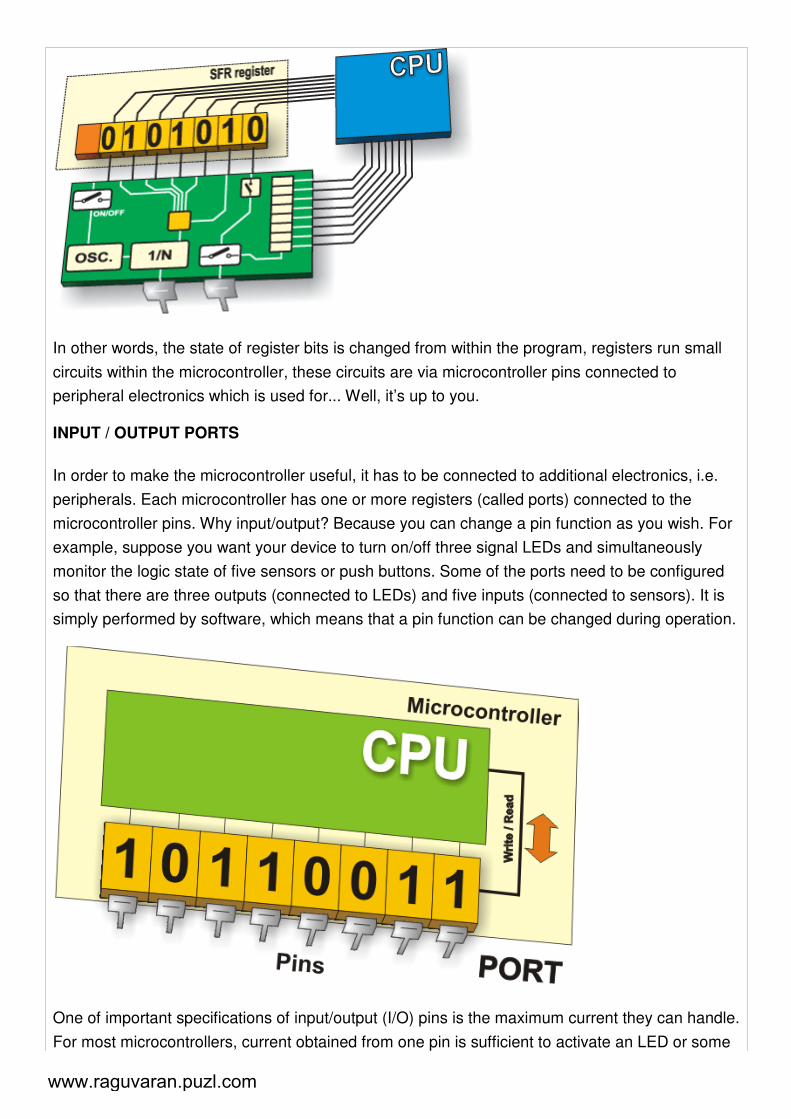
In other words, the state of register bits is changed from within the program, registers run small
circuits within the microcontroller, these circuits are via microcontroller pins connected to
peripheral electronics which is used for... Well, it’s up to you.
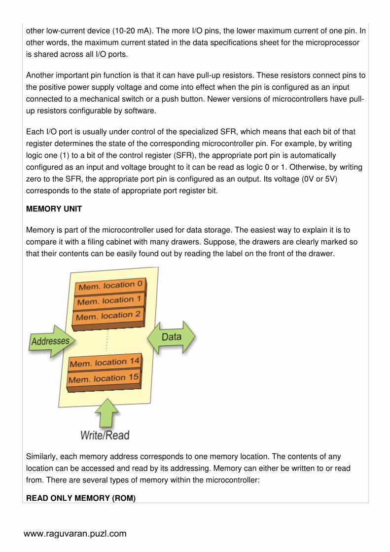
INPUT / OUTPUT PORTS
In order to make the microcontroller useful, it has to be connected to additional electronics, i.e.
peripherals. Each microcontroller has one or more registers (called ports) connected to the
microcontroller pins. Why input/output? Because you can change a pin function as you wish. For
example, suppose you want your device to turn on/off three signal LEDs and simultaneously
monitor the logic state of five sensors or push buttons. Some of the ports need to be configured
so that there are three outputs (connected to LEDs) and five inputs (connected to sensors). It is
simply performed by software, which means that a pin function can be changed during operation.
One of important specifications of input/output (I/O) pins is the maximum current they can handle.
For most microcontrollers, current obtained from one pin is sufficient to activate an LED or some
www.raguvaran.puzl.com
other low-current device (10-20 mA). The more I/O pins, the lower maximum current of one pin. In
other words, the maximum current stated in the data specifications sheet for the microprocessor
is shared across all I/O ports.
Another important pin function is that it can have pull-up resistors. These resistors connect pins to
the positive power supply voltage and come into effect when the pin is configured as an input
connected to a mechanical switch or a push button. Newer versions of microcontrollers have pull-
up resistors configurable by software.
Each I/O port is usually under control of the specialized SFR, which means that each bit of that
register determines the state of the corresponding microcontroller pin. For example, by writing
logic one (1) to a bit of the control register (SFR), the appropriate port pin is automatically
configured as an input and voltage brought to it can be read as logic 0 or 1. Otherwise, by writing
zero to the SFR, the appropriate port pin is configured as an output. Its voltage (0V or 5V)
corresponds to the state of appropriate port register bit.
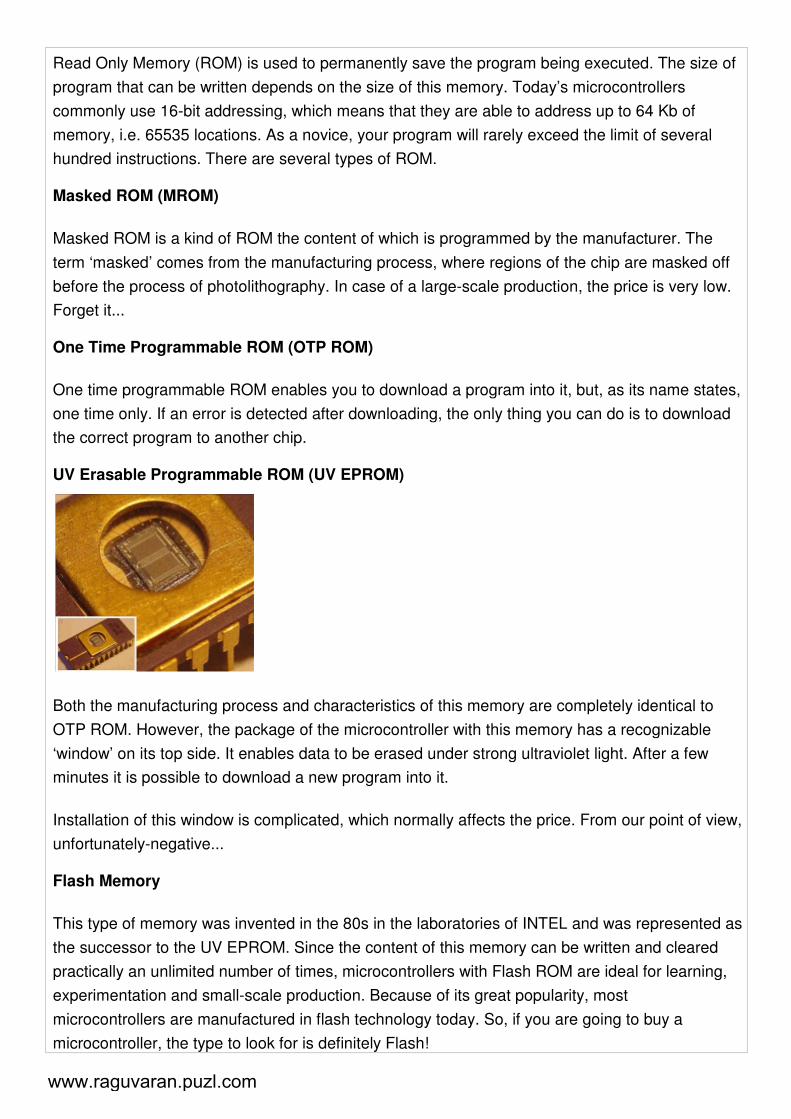
MEMORY UNIT
Memory is part of the microcontroller used for data storage. The easiest way to explain it is to
compare it with a filing cabinet with many drawers. Suppose, the drawers are clearly marked so
that their contents can be easily found out by reading the label on the front of the drawer.
Similarly, each memory address corresponds to one memory location. The contents of any
location can be accessed and read by its addressing. Memory can either be written to or read
from. There are several types of memory within the microcontroller:
READ ONLY MEMORY (ROM)
www.raguvaran.puzl.com
Read Only Memory (ROM) is used to permanently save the program being executed. The size of
program that can be written depends on the size of this memory. Today’s microcontrollers
commonly use 16-bit addressing, which means that they are able to address up to 64 Kb of
memory, i.e. 65535 locations. As a novice, your program will rarely exceed the limit of several
hundred instructions. There are several types of ROM.
Masked ROM (MROM)
Masked ROM is a kind of ROM the content of which is programmed by the manufacturer. The
term ‘masked’ comes from the manufacturing process, where regions of the chip are masked off
before the process of photolithography. In case of a large-scale production, the price is very low.
Forget it...
One Time Programmable ROM (OTP ROM)
One time programmable ROM enables you to download a program into it, but, as its name states,
one time only. If an error is detected after downloading, the only thing you can do is to download
the correct program to another chip.
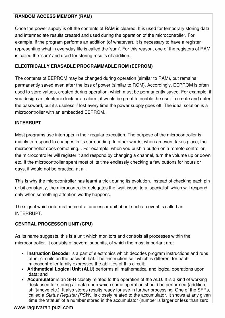
UV Erasable Programmable ROM (UV EPROM)
Both the manufacturing process and characteristics of this memory are completely identical to
OTP ROM. However, the package of the microcontroller with this memory has a recognizable
‘window’ on its top side. It enables data to be erased under strong ultraviolet light. After a few
minutes it is possible to download a new program into it.
Installation of this window is complicated, which normally affects the price. From our point of view,
unfortunately-negative...
Flash Memory
This type of memory was invented in the 80s in the laboratories of INTEL and was represented as
the successor to the UV EPROM. Since the content of this memory can be written and cleared
practically an unlimited number of times, microcontrollers with Flash ROM are ideal for learning,
experimentation and small-scale production. Because of its great popularity, most
microcontrollers are manufactured in flash technology today. So, if you are going to buy a
microcontroller, the type to look for is definitely Flash!
www.raguvaran.puzl.com
RANDOM ACCESS MEMORY (RAM)
Once the power supply is off the contents of RAM is cleared. It is used for temporary storing data
and intermediate results created and used during the operation of the microcontroller. For
example, if the program performs an addition (of whatever), it is necessary to have a register
representing what in everyday life is called the ‘sum’. For this reason, one of the registers of RAM
is called the ‘sum’ and used for storing results of addition.
ELECTRICALLY ERASABLE PROGRAMMABLE ROM (EEPROM)
The contents of EEPROM may be changed during operation (similar to RAM), but remains
permanently saved even after the loss of power (similar to ROM). Accordingly, EEPROM is often
used to store values, created during operation, which must be permanently saved. For example, if
you design an electronic lock or an alarm, it would be great to enable the user to create and enter
the password, but it’s useless if lost every time the power supply goes off. The ideal solution is a
microcontroller with an embedded EEPROM.
INTERRUPT
Most programs use interrupts in their regular execution. The purpose of the microcontroller is
mainly to respond to changes in its surrounding. In other words, when an event takes place, the
microcontroller does something... For example, when you push a button on a remote controller,
the microcontroller will register it and respond by changing a channel, turn the volume up or down
etc. If the microcontroller spent most of its time endlessly checking a few buttons for hours or
days, it would not be practical at all.
This is why the microcontroller has learnt a trick during its evolution. Instead of checking each pin
or bit constantly, the microcontroller delegates the ‘wait issue’ to a ‘specialist’ which will respond
only when something attention worthy happens.
The signal which informs the central processor unit about such an event is called an
INTERRUPT.
CENTRAL PROCESSOR UNIT (CPU)
As its name suggests, this is a unit which monitors and controls all processes within the
microcontroller. It consists of several subunits, of which the most important are:
• Instruction Decoder is a part of electronics which decodes program instructions and runs other circuits on the basis of that. The ‘instruction set’ which is different for each microcontroller family expresses the abilities of this circuit;
• Arithmetical Logical Unit (ALU) performs all mathematical and logical operations upon data; and
• Accumulator is an SFR closely related to the operation of the ALU. It is a kind of working desk used for storing all data upon which some operation should be performed (addition, shift/move etc.). It also stores results ready for use in further processing. One of the SFRs, called a Status Register (PSW), is closely related to the accumulator. It shows at any given time the ‘status’ of a number stored in the accumulator (number is larger or less than zero
www.raguvaran.puzl.com
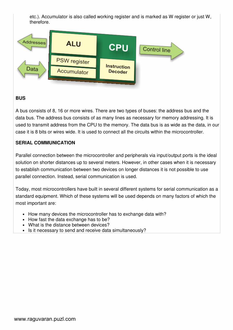
etc.). Accumulator is also called working register and is marked as W register or just W, therefore.
BUS
A bus consists of 8, 16 or more wires. There are two types of buses: the address bus and the
data bus. The address bus consists of as many lines as necessary for memory addressing. It is
used to transmit address from the CPU to the memory. The data bus is as wide as the data, in our
case it is 8 bits or wires wide. It is used to connect all the circuits within the microcontroller.
SERIAL COMMUNICATION
Parallel connection between the microcontroller and peripherals via input/output ports is the ideal
solution on shorter distances up to several meters. However, in other cases when it is necessary
to establish communication between two devices on longer distances it is not possible to use
parallel connection. Instead, serial communication is used.
Today, most microcontrollers have built in several different systems for serial communication as a
standard equipment. Which of these systems will be used depends on many factors of which the
most important are:
• How many devices the microcontroller has to exchange data with? • How fast the data exchange has to be? • What is the distance between devices? • Is it necessary to send and receive data simultaneously?
www.raguvaran.puzl.com
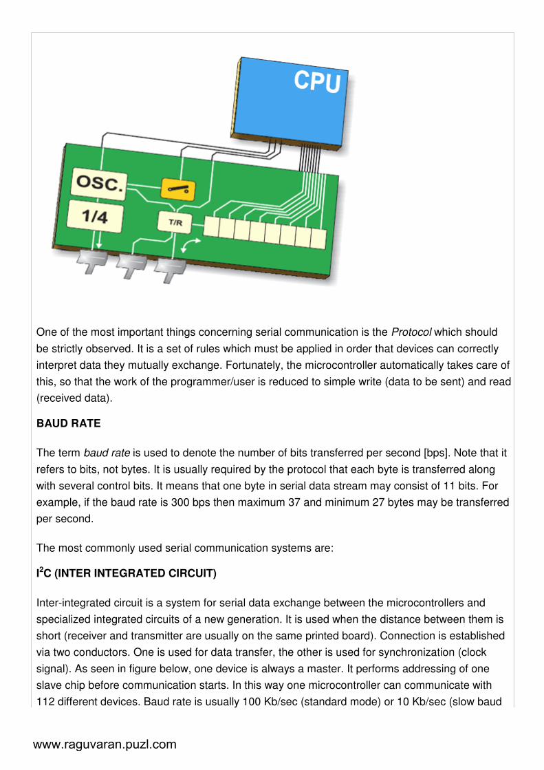
One of the most important things concerning serial communication is the Protocol which should
be strictly observed. It is a set of rules which must be applied in order that devices can correctly
interpret data they mutually exchange. Fortunately, the microcontroller automatically takes care of
this, so that the work of the programmer/user is reduced to simple write (data to be sent) and read
(received data).
BAUD RATE
The term baud rate is used to denote the number of bits transferred per second [bps]. Note that it
refers to bits, not bytes. It is usually required by the protocol that each byte is transferred along
with several control bits. It means that one byte in serial data stream may consist of 11 bits. For
example, if the baud rate is 300 bps then maximum 37 and minimum 27 bytes may be transferred
per second.
The most commonly used serial communication systems are:
I2C (INTER INTEGRATED CIRCUIT)
Inter-integrated circuit is a system for serial data exchange between the microcontrollers and
specialized integrated circuits of a new generation. It is used when the distance between them is
short (receiver and transmitter are usually on the same printed board). Connection is established
via two conductors. One is used for data transfer, the other is used for synchronization (clock
signal). As seen in figure below, one device is always a master. It performs addressing of one
slave chip before communication starts. In this way one microcontroller can communicate with
112 different devices. Baud rate is usually 100 Kb/sec (standard mode) or 10 Kb/sec (slow baud
www.raguvaran.puzl.com
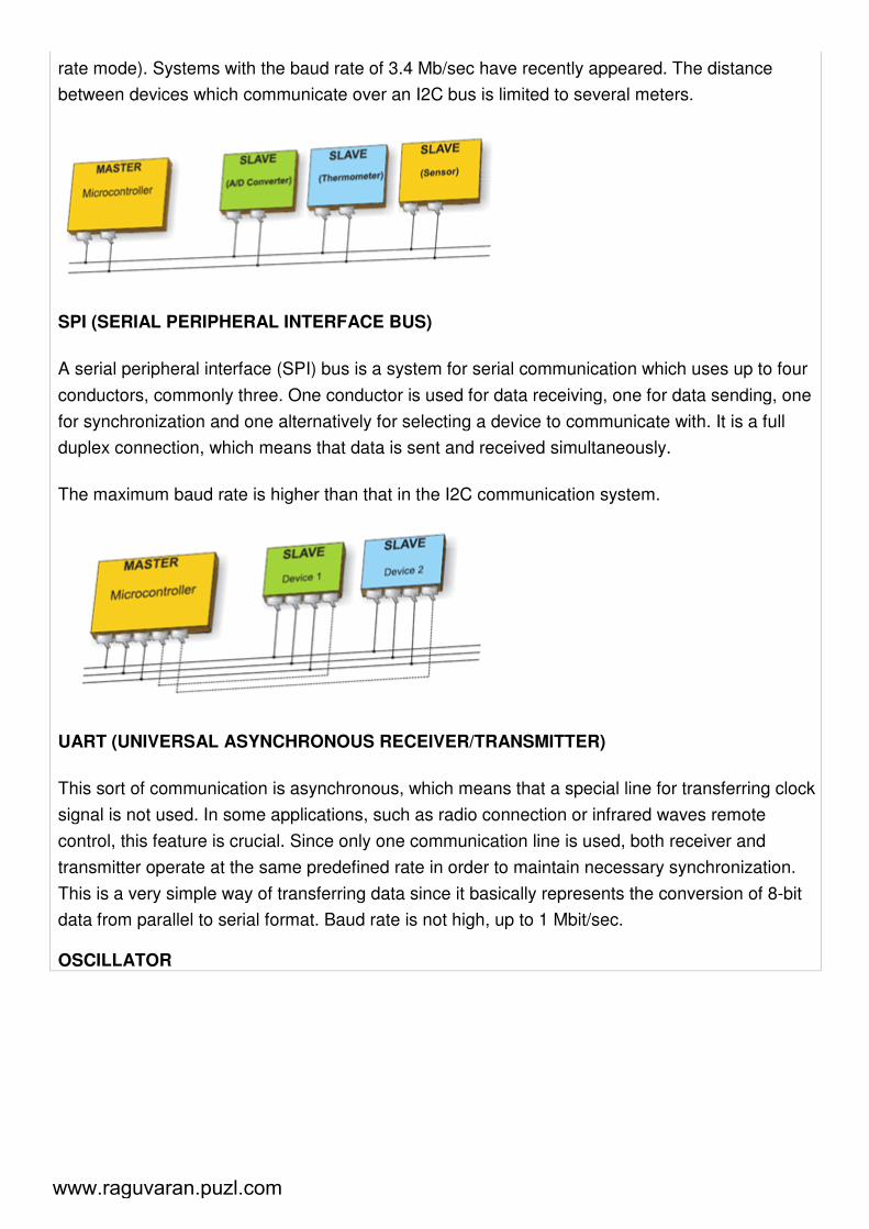
rate mode). Systems with the baud rate of 3.4 Mb/sec have recently appeared. The distance
between devices which communicate over an I2C bus is limited to several meters.
SPI (SERIAL PERIPHERAL INTERFACE BUS)
A serial peripheral interface (SPI) bus is a system for serial communication which uses up to four
conductors, commonly three. One conductor is used for data receiving, one for data sending, one
for synchronization and one alternatively for selecting a device to communicate with. It is a full
duplex connection, which means that data is sent and received simultaneously.
The maximum baud rate is higher than that in the I2C communication system.
UART (UNIVERSAL ASYNCHRONOUS RECEIVER/TRANSMITTER)
This sort of communication is asynchronous, which means that a special line for transferring clock
signal is not used. In some applications, such as radio connection or infrared waves remote
control, this feature is crucial. Since only one communication line is used, both receiver and
transmitter operate at the same predefined rate in order to maintain necessary synchronization.
This is a very simple way of transferring data since it basically represents the conversion of 8-bit
data from parallel to serial format. Baud rate is not high, up to 1 Mbit/sec.
OSCILLATOR
www.raguvaran.puzl.com

Even pulses generated by the oscillator enable harmonic and synchronous operation of all circuits
within the microcontroller. The oscillator is usually configured so as to use quartz crystal or
ceramic resonator for frequency stability, but it can also operate as a stand-alone circuit (like RC
oscillator). It is important to say that instructions are not executed at the rate imposed by the
oscillator itself, but several times slower. It happens because each instruction is executed in
several steps. In some microcontrollers, the same number of cycles is needed to execute all
instructions, while in others, the number of cycles is different for different instructions.
Accordingly, if the system uses quartz crystal with a frequency of 20 Mhz, the execution time of
an instruction is not 50nS, but 200, 400 or 800 nS, depending on the type of MCU!
POWER SUPPLY CIRCUIT
There are two things worth attention concerning the microcontroller power supply circuit:
• Brown out is a potentially dangerous condition which occurs at the moment the microcontroller is being turned off or when the power supply voltage drops to a minimum due to electric noise. As the microcontroller consists of several circuits with different operating voltage levels, this state can cause its out-of-control performance. In order to prevent it, the microcontroller usually has a built-in circuit for brown out reset which resets the whole electronics as soon as the microcontroller incurs a state of emergency.
• Reset pin is usually marked as MCLR (Master Clear Reset). It is used for external reset of the microcontroller by applying a logic zero (0) or one (1) to it, which depends on the type of the microcontroller. In case the brown out circuit is not built in, a simple external circuit for brown out reset can be connected to the MCLR pin.
TIMERS/COUNTERS
The microcontroller oscillator uses quartz crystal for its operation. Even though it is not the
simplest solution, there are many reasons to use it. The frequency of such oscillator is precisely
defined and very stable, so that pulses it generates are always of the same width, which makes
them ideal for time measurement. Such oscillators are also used in quartz watches. If it is
www.raguvaran.puzl.com
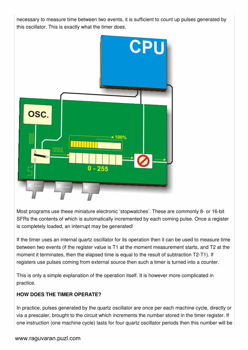
necessary to measure time between two events, it is sufficient to count up pulses generated by
this oscillator. This is exactly what the timer does.
Most programs use these miniature electronic ‘stopwatches’. These are commonly 8- or 16-bit
SFRs the contents of which is automatically incremented by each coming pulse. Once a register
is completely loaded, an interrupt may be generated!
If the timer uses an internal quartz oscillator for its operation then it can be used to measure time
between two events (if the register value is T1 at the moment measurement starts, and T2 at the
moment it terminates, then the elapsed time is equal to the result of subtraction T2-T1). If
registers use pulses coming from external source then such a timer is turned into a counter.
This is only a simple explanation of the operation itself. It is however more complicated in
practice.
HOW DOES THE TIMER OPERATE?
In practice, pulses generated by the quartz oscillator are once per each machine cycle, directly or
via a prescaler, brought to the circuit which increments the number stored in the timer register. If
one instruction (one machine cycle) lasts for four quartz oscillator periods then this number will be
www.raguvaran.puzl.com
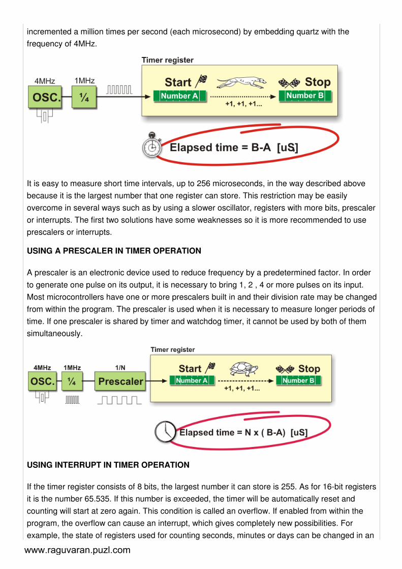
incremented a million times per second (each microsecond) by embedding quartz with the
frequency of 4MHz.
It is easy to measure short time intervals, up to 256 microseconds, in the way described above
because it is the largest number that one register can store. This restriction may be easily
overcome in several ways such as by using a slower oscillator, registers with more bits, prescaler
or interrupts. The first two solutions have some weaknesses so it is more recommended to use
prescalers or interrupts.
USING A PRESCALER IN TIMER OPERATION
A prescaler is an electronic device used to reduce frequency by a predetermined factor. In order
to generate one pulse on its output, it is necessary to bring 1, 2 , 4 or more pulses on its input.
Most microcontrollers have one or more prescalers built in and their division rate may be changed
from within the program. The prescaler is used when it is necessary to measure longer periods of
time. If one prescaler is shared by timer and watchdog timer, it cannot be used by both of them
simultaneously.
USING INTERRUPT IN TIMER OPERATION
If the timer register consists of 8 bits, the largest number it can store is 255. As for 16-bit registers
it is the number 65.535. If this number is exceeded, the timer will be automatically reset and
counting will start at zero again. This condition is called an overflow. If enabled from within the
program, the overflow can cause an interrupt, which gives completely new possibilities. For
example, the state of registers used for counting seconds, minutes or days can be changed in an
www.raguvaran.puzl.com
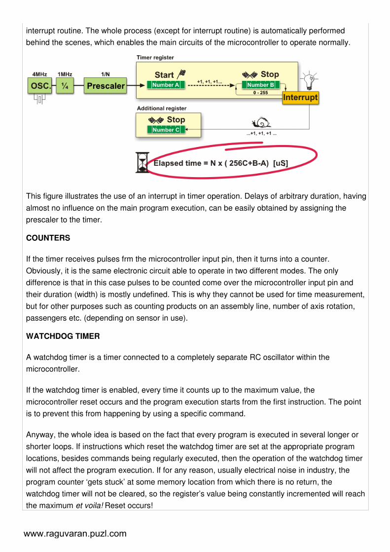
interrupt routine. The whole process (except for interrupt routine) is automatically performed
behind the scenes, which enables the main circuits of the microcontroller to operate normally.
This figure illustrates the use of an interrupt in timer operation. Delays of arbitrary duration, having
almost no influence on the main program execution, can be easily obtained by assigning the
prescaler to the timer.
COUNTERS
If the timer receives pulses frm the microcontroller input pin, then it turns into a counter.
Obviously, it is the same electronic circuit able to operate in two different modes. The only
difference is that in this case pulses to be counted come over the microcontroller input pin and
their duration (width) is mostly undefined. This is why they cannot be used for time measurement,
but for other purposes such as counting products on an assembly line, number of axis rotation,
passengers etc. (depending on sensor in use).
WATCHDOG TIMER
A watchdog timer is a timer connected to a completely separate RC oscillator within the
microcontroller.
If the watchdog timer is enabled, every time it counts up to the maximum value, the
microcontroller reset occurs and the program execution starts from the first instruction. The point
is to prevent this from happening by using a specific command.
Anyway, the whole idea is based on the fact that every program is executed in several longer or
shorter loops. If instructions which reset the watchdog timer are set at the appropriate program
locations, besides commands being regularly executed, then the operation of the watchdog timer
will not affect the program execution. If for any reason, usually electrical noise in industry, the
program counter ‘gets stuck’ at some memory location from which there is no return, the
watchdog timer will not be cleared, so the register’s value being constantly incremented will reach
the maximum et voila! Reset occurs!
www.raguvaran.puzl.com
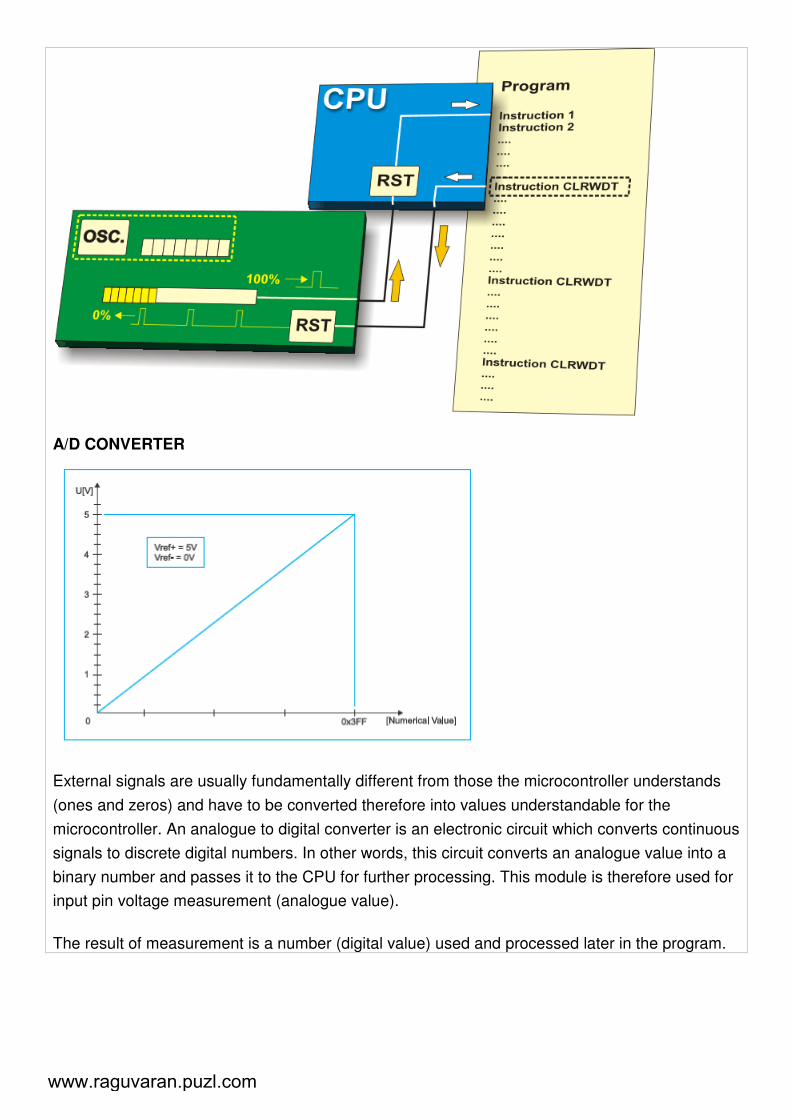
A/D CONVERTER
External signals are usually fundamentally different from those the microcontroller understands
(ones and zeros) and have to be converted therefore into values understandable for the
microcontroller. An analogue to digital converter is an electronic circuit which converts continuous
signals to discrete digital numbers. In other words, this circuit converts an analogue value into a
binary number and passes it to the CPU for further processing. This module is therefore used for
input pin voltage measurement (analogue value).
The result of measurement is a number (digital value) used and processed later in the program.
www.raguvaran.puzl.com
INTERNAL ARCHITECTURE
All upgraded microcontrollers use one of two basic design models called Harvard and von-
Neumann architecture.
They represent two different ways of exchanging data between CPU and memory.
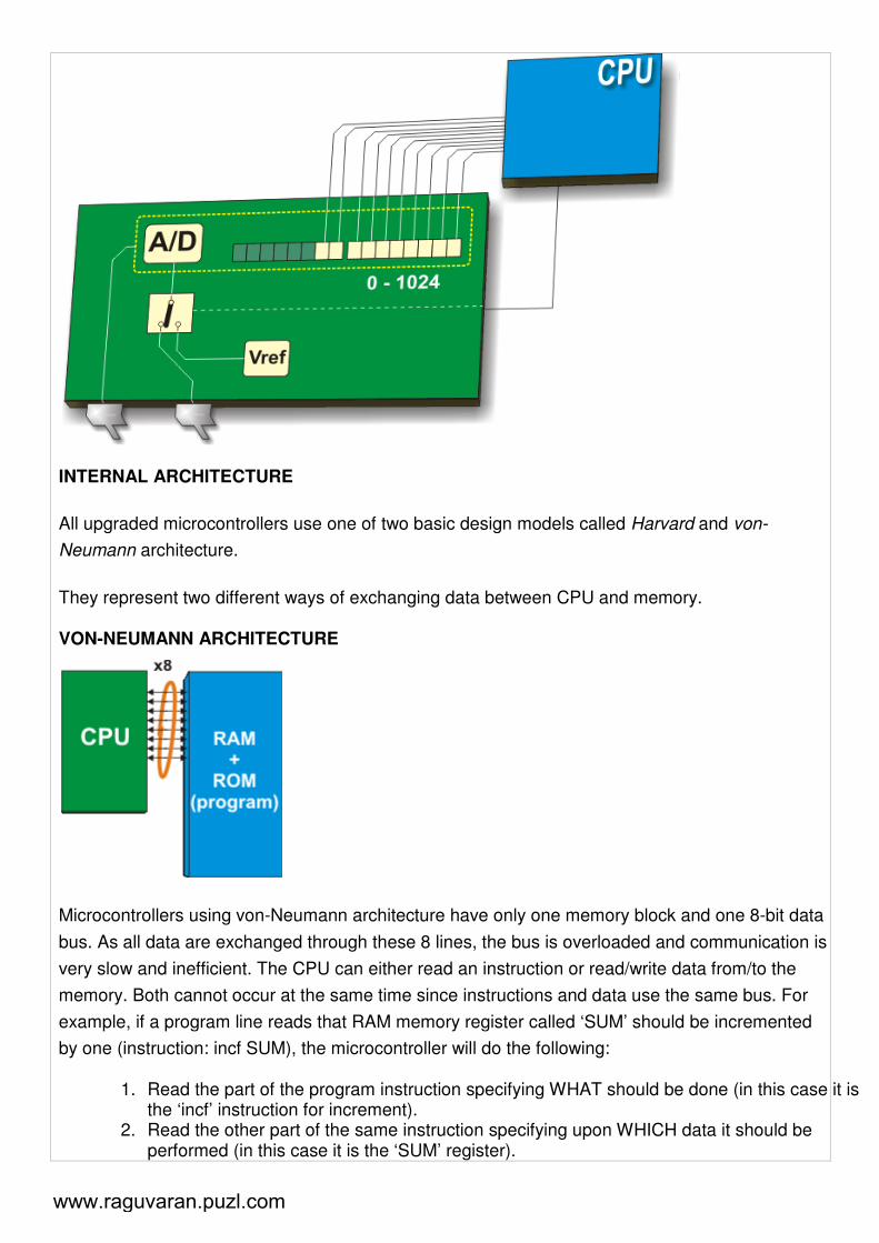
VON-NEUMANN ARCHITECTURE
Microcontrollers using von-Neumann architecture have only one memory block and one 8-bit data
bus. As all data are exchanged through these 8 lines, the bus is overloaded and communication is
very slow and inefficient. The CPU can either read an instruction or read/write data from/to the
memory. Both cannot occur at the same time since instructions and data use the same bus. For
example, if a program line reads that RAM memory register called ‘SUM’ should be incremented
by one (instruction: incf SUM), the microcontroller will do the following:
1. Read the part of the program instruction specifying WHAT should be done (in this case it is the ‘incf’ instruction for increment).
2. Read the other part of the same instruction specifying upon WHICH data it should be performed (in this case it is the ‘SUM’ register).
www.raguvaran.puzl.com
3. After being incremented, the contents of this register should be written to the register from which it was read (‘SUM’ register address).
The same data bus is used for all these intermediate operations.
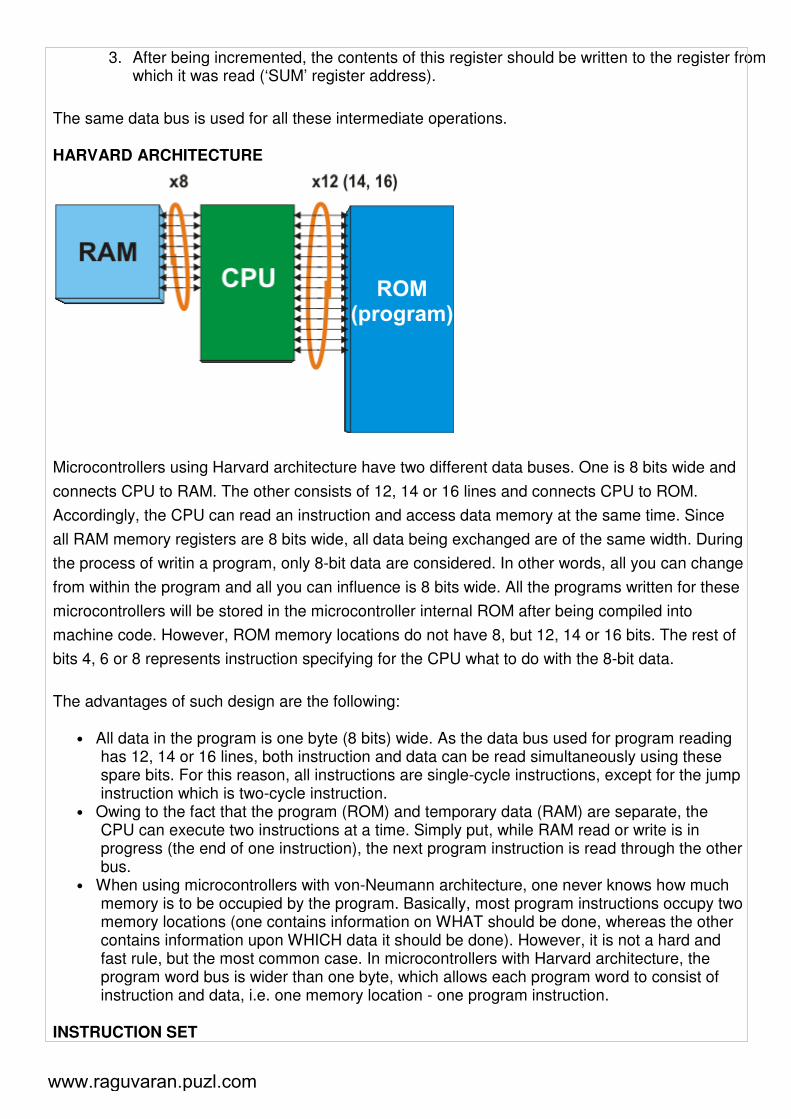
HARVARD ARCHITECTURE
Microcontrollers using Harvard architecture have two different data buses. One is 8 bits wide and
connects CPU to RAM. The other consists of 12, 14 or 16 lines and connects CPU to ROM.
Accordingly, the CPU can read an instruction and access data memory at the same time. Since
all RAM memory registers are 8 bits wide, all data being exchanged are of the same width. During
the process of writin a program, only 8-bit data are considered. In other words, all you can change
from within the program and all you can influence is 8 bits wide. All the programs written for these
microcontrollers will be stored in the microcontroller internal ROM after being compiled into
machine code. However, ROM memory locations do not have 8, but 12, 14 or 16 bits. The rest of
bits 4, 6 or 8 represents instruction specifying for the CPU what to do with the 8-bit data.
The advantages of such design are the following:
• All data in the program is one byte (8 bits) wide. As the data bus used for program reading has 12, 14 or 16 lines, both instruction and data can be read simultaneously using these spare bits. For this reason, all instructions are single-cycle instructions, except for the jump instruction which is two-cycle instruction.
• Owing to the fact that the program (ROM) and temporary data (RAM) are separate, the CPU can execute two instructions at a time. Simply put, while RAM read or write is in progress (the end of one instruction), the next program instruction is read through the other bus.
• When using microcontrollers with von-Neumann architecture, one never knows how much memory is to be occupied by the program. Basically, most program instructions occupy two memory locations (one contains information on WHAT should be done, whereas the other contains information upon WHICH data it should be done). However, it is not a hard and fast rule, but the most common case. In microcontrollers with Harvard architecture, the program word bus is wider than one byte, which allows each program word to consist of instruction and data, i.e. one memory location - one program instruction.
INSTRUCTION SET
www.raguvaran.puzl.com
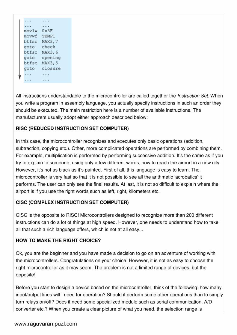
All instructions understandable to the microcontroller are called together the Instruction Set. When
you write a program in assembly language, you actually specify instructions in such an order they
should be executed. The main restriction here is a number of available instructions. The
manufacturers usually adopt either approach described below:
RISC (REDUCED INSTRUCTION SET COMPUTER)
In this case, the microcontroller recognizes and executes only basic operations (addition,
subtraction, copying etc.). Other, more complicated operations are performed by combining them.
For example, multiplication is performed by performing successive addition. It’s the same as if you
try to explain to someone, using only a few different words, how to reach the airport in a new city.
However, it’s not as black as it’s painted. First of all, this language is easy to learn. The
microcontroller is very fast so that it is not possible to see all the arithmetic ‘acrobatics’ it
performs. The user can only see the final results. At last, it is not so difficult to explain where the
airport is if you use the right words such as left, right, kilometers etc.
CISC (COMPLEX INSTRUCTION SET COMPUTER)
CISC is the opposite to RISC! Microcontrollers designed to recognize more than 200 different
instructions can do a lot of things at high speed. However, one needs to understand how to take
all that such a rich language offers, which is not at all easy...
HOW TO MAKE THE RIGHT CHOICE?
Ok, you are the beginner and you have made a decision to go on an adventure of working with
the microcontrollers. Congratulations on your choice! However, it is not as easy to choose the
right microcontroller as it may seem. The problem is not a limited range of devices, but the
opposite!
Before you start to design a device based on the microcontroller, think of the following: how many
input/output lines will I need for operation? Should it perform some other operations than to simply
turn relays on/off? Does it need some specialized module such as serial communication, A/D
converter etc.? When you create a clear picture of what you need, the selection range is
www.raguvaran.puzl.com
considerably reduced and it’s time to think of price. Are you planning to have several same
devices? Several hundred? A million? Anyway, you get the point.
If you think of all these things for the very first time then everything seems a bit confusing. For this
reason, go step by step. First of all, select the manufacturer, i.e. the microcontroller family you
can easily get. Study one particular model. Learn as much as you need, don’t go into details.
Solve a specific problem and something incredible will happen- you will be able to handle any
model belonging to that microcontroller family.
Remember learning to ride a bicycle. After several bruises at the beginning, you were able to
keep balance, then to easily ride any other bicycle. And of course, you will never forget
programming just as you will never forget riding bicycles!
1.4 PIC MICROCONTROLLERS
PIC microcontrollers designed by Microchip Technology are likely the best choice for beginners.
Here is why...
The original name of this microcontroller is PICmicro (Peripheral Interface Controller), but it is
better known as PIC. Its ancestor, called the PIC1650, was designed in 1975 by General
Instruments. It was meant for totally different purposes. Around ten years later, this circuit was
transformed into a real PIC microcontroller by adding EEPROM memory. Today, Microchip
Technology announces the manufacture of the 5 billionth sample.
If you are interested in learning more about it, just keep on reading.
The main idea with this book is to provide the user with necessary information so that he is able to
use microcontrollers in practice after reading it. In order to avoid tedious explanations and endless
story about the useful features of different microcontrollers, this book describes the operation of
one particular model belonging to the ‘high middle class’. It is the PIC16F887- powerful enough to
be worth attention and simple enough to be easily presented to everybody. So, the following
chapters describe this microcontroller in detail, but refer to the whole PIC family as well.
www.raguvaran.puzl.com
Family
ROM
[Kbytes]
RAM
[bytes]
Pi
ns
Clo
ck Fre
q. [M
Hz]
A/D
Inputs
Resol
ution of
A/D Conve
rter
Com
par- ators
8/16 –
bit Tim
ers
Serial
Comm.
PWM
Outputs
Oth
ers
Base-Line 8 - bit architecture, 12-bit Instruction Word Length
PIC10FX
XX
0.375
- 0.75
16 -
24
6 -
8
4 -
8
0 -
2 8 0 - 1
1 x
8 - - -
PIC12FXXX
0.75 - 1.5
25 - 38
8 4 - 8
0 - 3
8 0 - 1 1 x 8
- - EEPROM
PIC16FX
XX
0.75
- 3
25 -
134
14
- 44
20 0 -
3 8 0 - 2
1 x
8 - -
EEP
ROM
PIC16HVXXX
1.5 25 18 -
20
20 - - - 1 x 8
- - Vdd =
15V
Mid-Range 8 - bit architecture, 14-bit Instruction World Length
PIC12FXXX
1.75 - 3.5
64 - 128
8 20 0 - 4
10 1
1 -
2 x 8 1
x 16
- 0 - 1 EEPROM
PIC12HVXXX
1.75 64 8 20 0 - 4
10 1
1 -
2 x 8 1
x 16
- 0 - 1 -
PIC16FXXX
1.75 - 14
64 - 368
14 -
64
20 0 - 13
8 or 10 0 - 2
1 -
2 x 8 1
x 16
USA
RT I2C
SPI
0 - 3 -
PIC16HVXXX
1.75 - 3.5
64 - 128
14 -
20
20 0 - 12
10 2 2 x 8 1
x 16
USA
RT I2C
SPI
- -
High-End 8 - bit architecture, 16-bit Instruction Word Length
PIC18FXXX
4 - 128
256
- 393
6
18
- 80
32 - 48
4 - 16
10 or 12
0 - 3
0 -
2 x
8 2 - 3
x 16
USB
2.0 CAN
2.0 USA
RT I2C
SPI
0 - 5 -
www.raguvaran.puzl.com
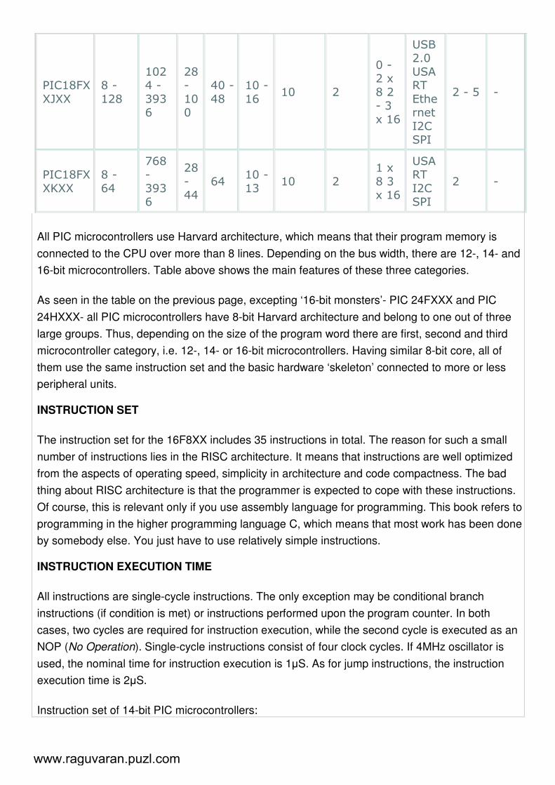
PIC18FX
XJXX
8 -
128
1024 -
3936
28 -
100
40 -
48
10 -
16 10 2
0 - 2 x
8 2 - 3
x 16
USB2.0
USART
Ethernet
I2C SPI
2 - 5 -
PIC18FX
XKXX
8 -
64
768 -
3936
28
- 44
64 10 -
13 10 2
1 x
8 3 x 16
USART
I2C SPI
2 -
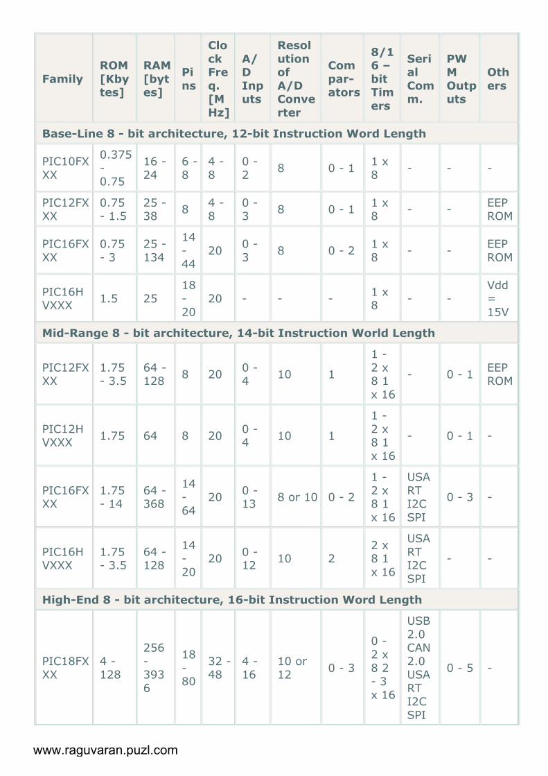
All PIC microcontrollers use Harvard architecture, which means that their program memory is
connected to the CPU over more than 8 lines. Depending on the bus width, there are 12-, 14- and
16-bit microcontrollers. Table above shows the main features of these three categories.
As seen in the table on the previous page, excepting ‘16-bit monsters’- PIC 24FXXX and PIC
24HXXX- all PIC microcontrollers have 8-bit Harvard architecture and belong to one out of three
large groups. Thus, depending on the size of the program word there are first, second and third
microcontroller category, i.e. 12-, 14- or 16-bit microcontrollers. Having similar 8-bit core, all of
them use the same instruction set and the basic hardware ‘skeleton’ connected to more or less
peripheral units.
INSTRUCTION SET
The instruction set for the 16F8XX includes 35 instructions in total. The reason for such a small
number of instructions lies in the RISC architecture. It means that instructions are well optimized
from the aspects of operating speed, simplicity in architecture and code compactness. The bad
thing about RISC architecture is that the programmer is expected to cope with these instructions.
Of course, this is relevant only if you use assembly language for programming. This book refers to
programming in the higher programming language C, which means that most work has been done
by somebody else. You just have to use relatively simple instructions.
INSTRUCTION EXECUTION TIME
All instructions are single-cycle instructions. The only exception may be conditional branch
instructions (if condition is met) or instructions performed upon the program counter. In both
cases, two cycles are required for instruction execution, while the second cycle is executed as an
NOP (No Operation). Single-cycle instructions consist of four clock cycles. If 4MHz oscillator is
used, the nominal time for instruction execution is 1µS. As for jump instructions, the instruction
execution time is 2µS.
Instruction set of 14-bit PIC microcontrollers:
www.raguvaran.puzl.com
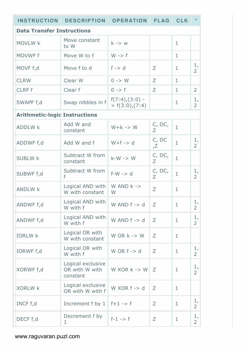
INSTRUCTION DESCRIPTION OPERATION FL AG CLK *
Data Transfer Instructions
MOVLW k Move constant
to W k -> w
1
MOVWF f Move W to f W -> f
1
MOVF f,d Move f to d f -> d Z 1 1,
2
CLRW Clear W 0 -> W Z 1
CLRF f Clear f 0 -> f Z 1 2
SWAPF f,d Swap nibbles in f f(7:4),(3:0) -> f(3:0),(7:4)
1 1, 2
Arithmetic-logic Instructions
ADDLW k Add W and constant
W+k -> W C, DC, Z
1
ADDWF f,d Add W and f W+f -> d C, DC
,Z 1
1,
2
SUBLW k Subtract W from
constant k-W -> W
C, DC,
Z 1
SUBWF f,d Subtract W from
f f-W -> d
C, DC,
Z 1
1,
2
ANDLW k Logical AND with W with constant
W AND k -> W
Z 1
ANDWF f,d Logical AND with W with f
W AND f -> d Z 1 1, 2
ANDWF f,d Logical AND with W with f
W AND f -> d Z 1 1, 2
IORLW k Logical OR with
W with constant W OR k -> W Z 1
IORWF f,d Logical OR with
W with f W OR f -> d Z 1
1,
2
XORWF f,d Logical exclusive OR with W with
constant
W XOR k -> W Z 1 1, 2
XORLW k Logical exclusive
OR with W with f W XOR f -> d Z 1
INCF f,d Increment f by 1 f+1 -> f Z 1 1,
2
DECF f,d Decrement f by 1
f-1 -> f Z 1 1, 2
www.raguvaran.puzl.com
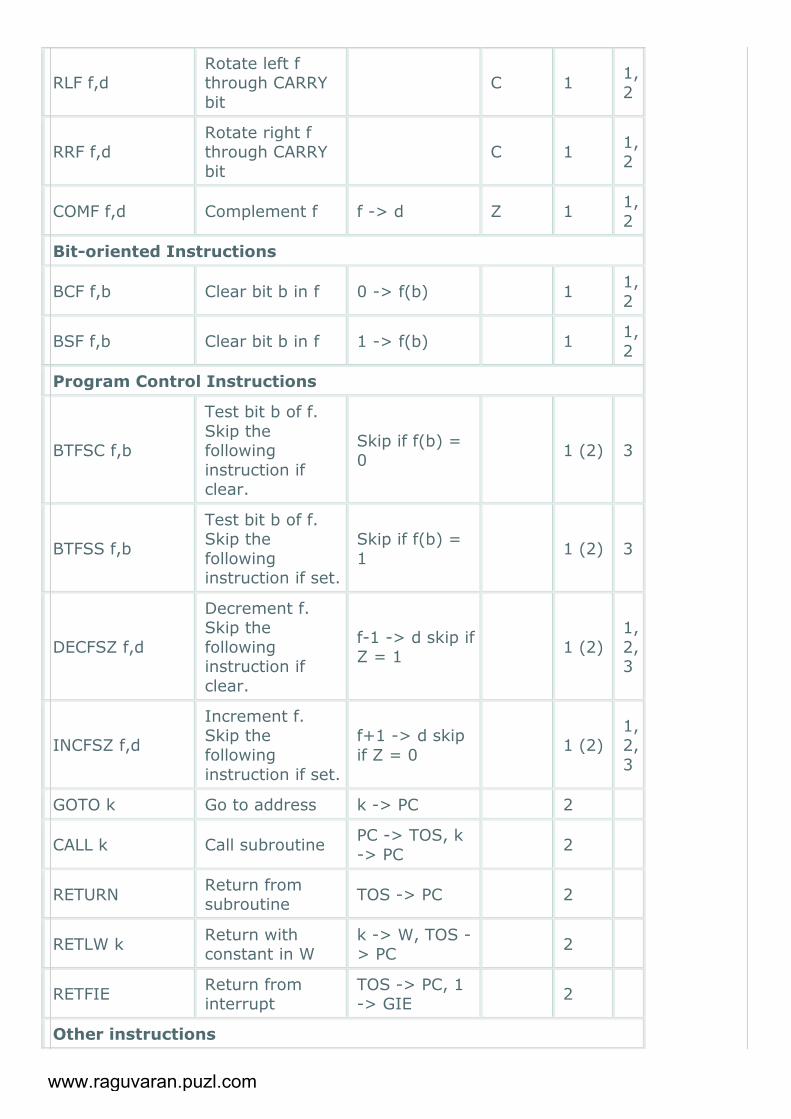
RLF f,d Rotate left f through CARRY
bit
C 1 1,
2
RRF f,d Rotate right f through CARRY
bit
C 1 1, 2
COMF f,d Complement f f -> d Z 1 1,
2
Bit-oriented Instructions
BCF f,b Clear bit b in f 0 -> f(b)
1 1,
2
BSF f,b Clear bit b in f 1 -> f(b)
1 1,
2
Program Control Instructions
BTFSC f,b
Test bit b of f.
Skip the following
instruction if clear.
Skip if f(b) = 0
1 (2) 3
BTFSS f,b
Test bit b of f. Skip the
following instruction if set.
Skip if f(b) =
1 1 (2) 3
DECFSZ f,d
Decrement f. Skip the
following instruction if
clear.
f-1 -> d skip if Z = 1
1 (2)
1,
2, 3
INCFSZ f,d
Increment f. Skip the
following
instruction if set.
f+1 -> d skip
if Z = 0 1 (2)
1, 2,
3
GOTO k Go to address k -> PC
2
CALL k Call subroutine PC -> TOS, k
-> PC 2
RETURN Return from subroutine
TOS -> PC
2
RETLW k Return with constant in W
k -> W, TOS -> PC
2
RETFIE Return from interrupt
TOS -> PC, 1 -> GIE
2
Other instructions
www.raguvaran.puzl.com

NOP No operation TOS -> PC, 1 -> GIE
1
CLRWDT Clear watchdog
timer
0 -> WDT, 1 -
> TO, 1 -> PD TO, PD 1
SLEEP Go into sleep
mode
0 -> WDT, 1 -
> TO, 0 -> PD TO, PD 1
*1 When an I/O register is modified as a function of itself, the value used will be that value present
on the pins themselves.
*2 If the instruction is executed on the TMR register and if d=1, the prescaler will be cleared.
*3 If the PC is modified or test result is logic one (1), the instruction requires two cycles.
www.raguvaran.puzl.com
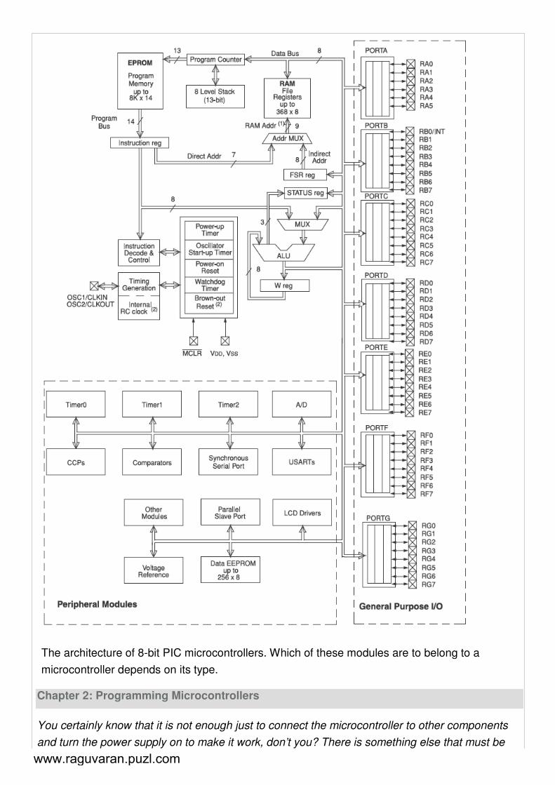
The architecture of 8-bit PIC microcontrollers. Which of these modules are to belong to a
microcontroller depends on its type.
Chapter 2: Programming Microcontrollers
You certainly know that it is not enough just to connect the microcontroller to other components
and turn the power supply on to make it work, don’t you? There is something else that must be
www.raguvaran.puzl.com

done. The microcontroller needs to be programmed to be capable of performing anything useful.
If you think that it is complicated, then you are mistaken. The whole procedure is very simple. Just
read the following text and you will change your mind.
• 2.1 PROGRAMMING LANGUAGES • 2.2 THE BASICS OF C PROGRAMMING LANGUAGE • 2.3 COMPILER MIKROC PRO FOR PIC
2.1 PROGRAMMING LANGUAGES
The microcontroller executes the program loaded in its Flash memory. This is the so called
executable code comprised of seemingly meaningless sequence of zeros and ones. It is
organized in 12-, 14- or 16-bit wide words, depending on the microcontroller’s architecture. Every
word is considered by the CPU as a command being executed during the operation of the
microcontroller. For practical reasons, as it is much easier for us to deal with hexadecimal number
system, the executable code is often represented as a sequence of hexadecimal numbers called
a Hex code. It used to be written by the programmer. All instructions that the microcontroller can
recognize are together called the Instruction set. As for PIC microcontrollers the programming
words of which are comprised of 14 bits, the instruction set has 35 different instructions in total.
As the process of writing executable code was endlessly tiring, the first ‘higher’ programming
language called assembly language was created. The truth is that it made the process of
programming more complicated, but on the other hand the process of writing program stopped
www.raguvaran.puzl.com

being a nightmare. Instructions in assembly language are represented in the form of meaningful
abbreviations, and the process of their compiling into executable code is left over to a special
program on a PC called compiler. The main advantage of this programming language is its
simplicity, i.e. each program instruction corresponds to one memory location in the
microcontroller. It enables a complete control of what is going on within the chip, thus making this
language commonly used today.
However, programmers have always needed a programming language close to the language
being used in everyday life. As a result, the higher programming languages have been created.
One of them is C. The main advantageof these languages is simplicity of program writing. It is no
longer possible to know exactly how each command executes, but it is no longer of interest
anyway. In case it is, a sequence written in assembly language can always be inserted in the
program, thus enabling it.
Similar to assembly language, a specialized program in a PC called compiler is in charge of
compiling program into machine language. Unlike assembly compilers, these create an
executable code which is not always the shortest possible.
Figures above give a rough illustration of what is going on during the process of compiling the
program from higher to lower programming language.
www.raguvaran.puzl.com
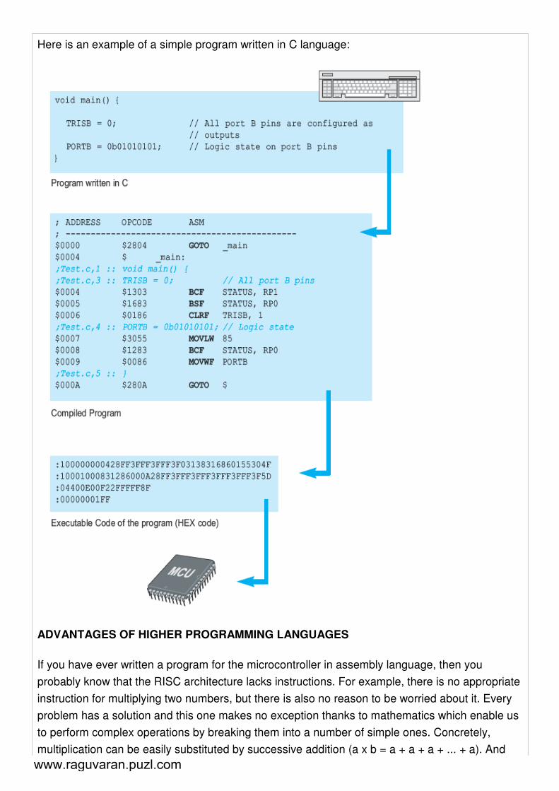
Here is an example of a simple program written in C language:
ADVANTAGES OF HIGHER PROGRAMMING LANGUAGES
If you have ever written a program for the microcontroller in assembly language, then you
probably know that the RISC architecture lacks instructions. For example, there is no appropriate
instruction for multiplying two numbers, but there is also no reason to be worried about it. Every
problem has a solution and this one makes no exception thanks to mathematics which enable us
to perform complex operations by breaking them into a number of simple ones. Concretely,
multiplication can be easily substituted by successive addition (a x b = a + a + a + ... + a). And
www.raguvaran.puzl.com
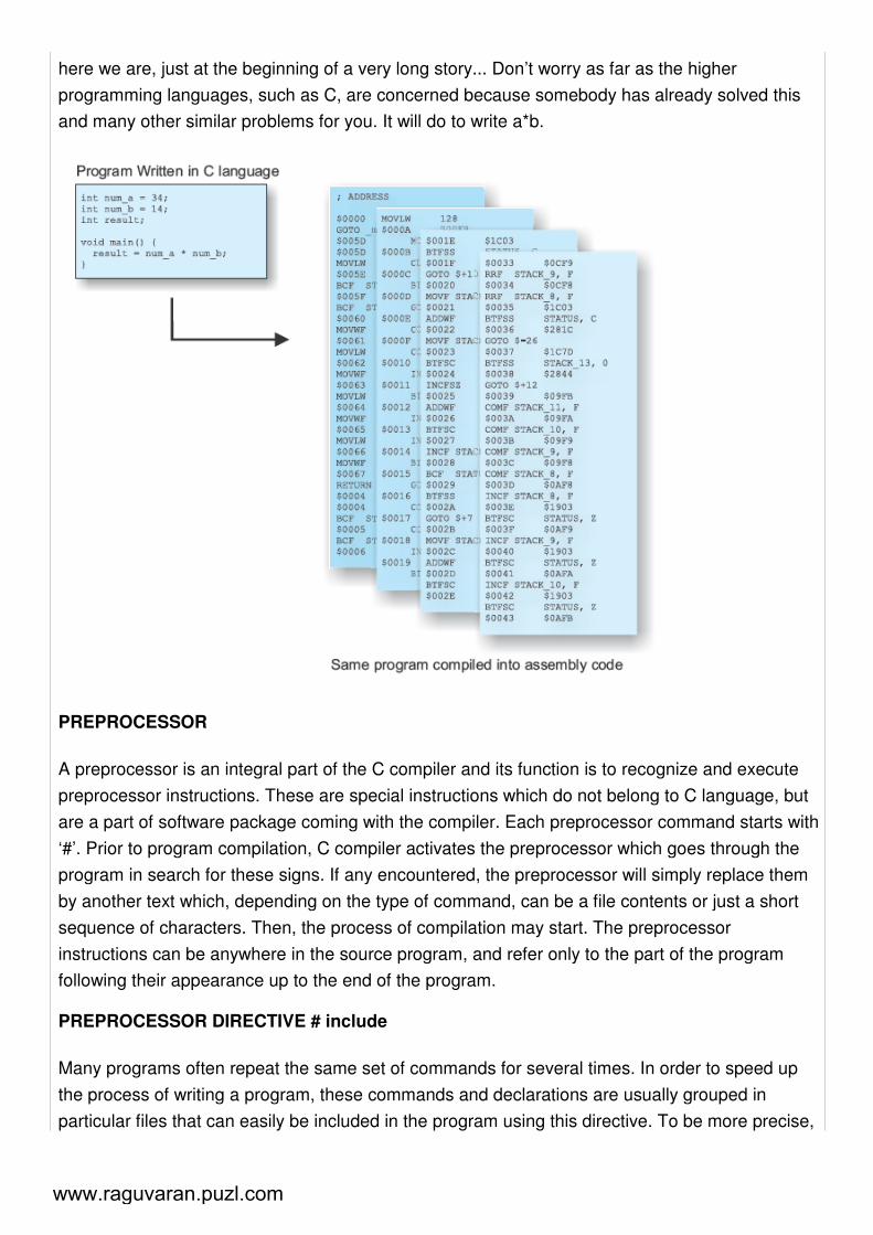
here we are, just at the beginning of a very long story... Don’t worry as far as the higher
programming languages, such as C, are concerned because somebody has already solved this
and many other similar problems for you. It will do to write a*b.
PREPROCESSOR
A preprocessor is an integral part of the C compiler and its function is to recognize and execute
preprocessor instructions. These are special instructions which do not belong to C language, but
are a part of software package coming with the compiler. Each preprocessor command starts with
‘#’. Prior to program compilation, C compiler activates the preprocessor which goes through the
program in search for these signs. If any encountered, the preprocessor will simply replace them
by another text which, depending on the type of command, can be a file contents or just a short
sequence of characters. Then, the process of compilation may start. The preprocessor
instructions can be anywhere in the source program, and refer only to the part of the program
following their appearance up to the end of the program.
PREPROCESSOR DIRECTIVE # include
Many programs often repeat the same set of commands for several times. In order to speed up
the process of writing a program, these commands and declarations are usually grouped in
particular files that can easily be included in the program using this directive. To be more precise,
www.raguvaran.puzl.com
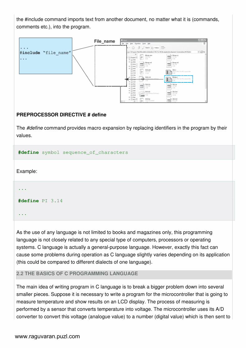
the #include command imports text from another document, no matter what it is (commands,
comments etc.), into the program.
PREPROCESSOR DIRECTIVE # define
The #define command provides macro expansion by replacing identifiers in the program by their
values.
#define symbol sequence_of_characters
Example:
...
#define PI 3.14
...
As the use of any language is not limited to books and magazines only, this programming
language is not closely related to any special type of computers, processors or operating
systems. C language is actually a general-purpose language. However, exactly this fact can
cause some problems during operation as C language slightly varies depending on its application
(this could be compared to different dialects of one language).
2.2 THE BASICS OF C PROGRAMMING LANGUAGE
The main idea of writing program in C language is to break a bigger problem down into several
smaller pieces. Suppose it is necessary to write a program for the microcontroller that is going to
measure temperature and show results on an LCD display. The process of measuring is
performed by a sensor that converts temperature into voltage. The microcontroller uses its A/D
converter to convert this voltage (analogue value) to a number (digital value) which is then sent to
www.raguvaran.puzl.com
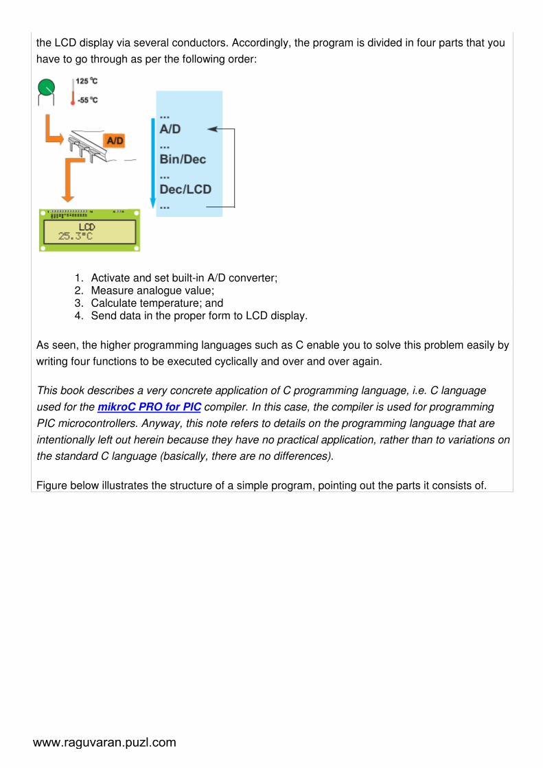
the LCD display via several conductors. Accordingly, the program is divided in four parts that you
have to go through as per the following order:
1. Activate and set built-in A/D converter; 2. Measure analogue value; 3. Calculate temperature; and 4. Send data in the proper form to LCD display.
As seen, the higher programming languages such as C enable you to solve this problem easily by
writing four functions to be executed cyclically and over and over again.
This book describes a very concrete application of C programming language, i.e. C language
used for the mikroC PRO for PIC compiler. In this case, the compiler is used for programming
PIC microcontrollers. Anyway, this note refers to details on the programming language that are
intentionally left out herein because they have no practical application, rather than to variations on
the standard C language (basically, there are no differences).
Figure below illustrates the structure of a simple program, pointing out the parts it consists of.
www.raguvaran.puzl.com
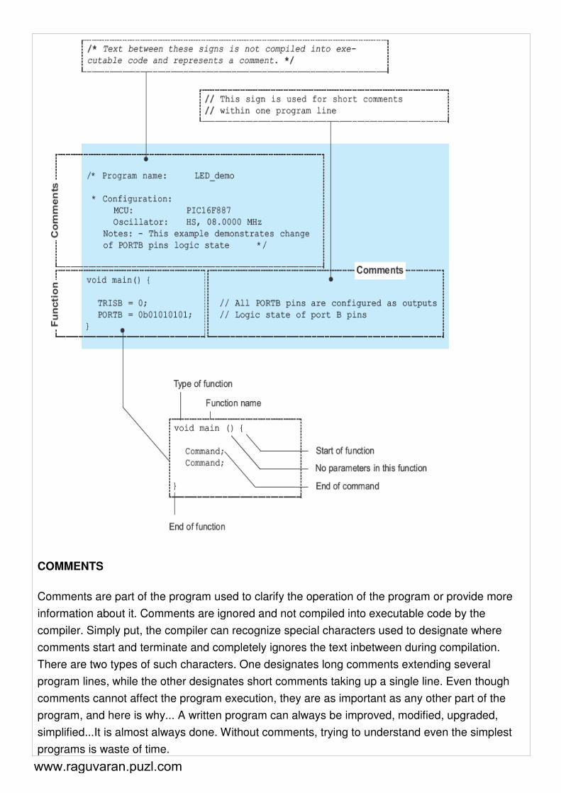
COMMENTS
Comments are part of the program used to clarify the operation of the program or provide more
information about it. Comments are ignored and not compiled into executable code by the
compiler. Simply put, the compiler can recognize special characters used to designate where
comments start and terminate and completely ignores the text inbetween during compilation.
There are two types of such characters. One designates long comments extending several
program lines, while the other designates short comments taking up a single line. Even though
comments cannot affect the program execution, they are as important as any other part of the
program, and here is why... A written program can always be improved, modified, upgraded,
simplified...It is almost always done. Without comments, trying to understand even the simplest
programs is waste of time.
www.raguvaran.puzl.com
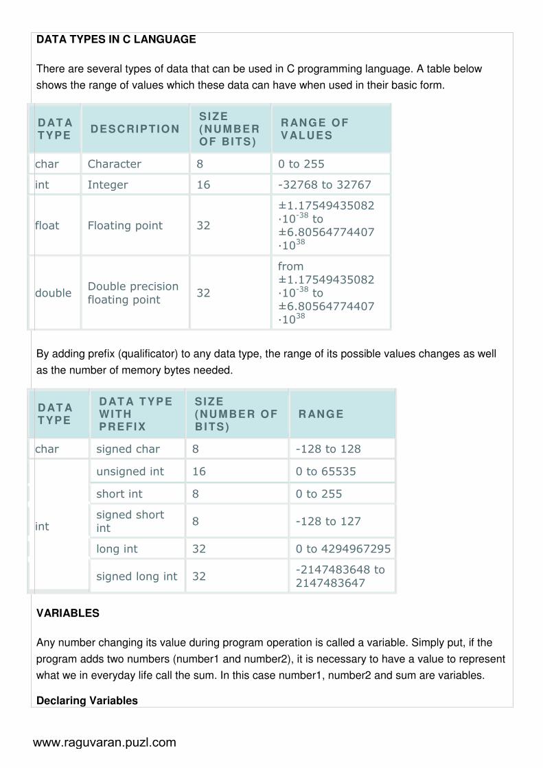
DATA TYPES IN C LANGUAGE
There are several types of data that can be used in C programming language. A table below
shows the range of values which these data can have when used in their basic form.
DAT A TYPE
DESCRIPTION SIZE (NUMBER OF BITS)
RANGE OF V ALUES
char Character 8 0 to 255
int Integer 16 -32768 to 32767
float Floating point 32
±1.17549435082
·10-38 to ±6.80564774407
·1038
double Double precision
floating point 32
from
±1.17549435082 ·10-38 to
±6.80564774407 ·1038
By adding prefix (qualificator) to any data type, the range of its possible values changes as well
as the number of memory bytes needed.
DAT A TYPE
DAT A TYPE WITH PREFIX
S IZE (NUMBER OF BITS)
RANGE
char signed char 8 -128 to 128
int
unsigned int 16 0 to 65535
short int 8 0 to 255
signed short
int 8 -128 to 127
long int 32 0 to 4294967295
signed long int 32 -2147483648 to
2147483647
VARIABLES
Any number changing its value during program operation is called a variable. Simply put, if the
program adds two numbers (number1 and number2), it is necessary to have a value to represent
what we in everyday life call the sum. In this case number1, number2 and sum are variables.
Declaring Variables
www.raguvaran.puzl.com
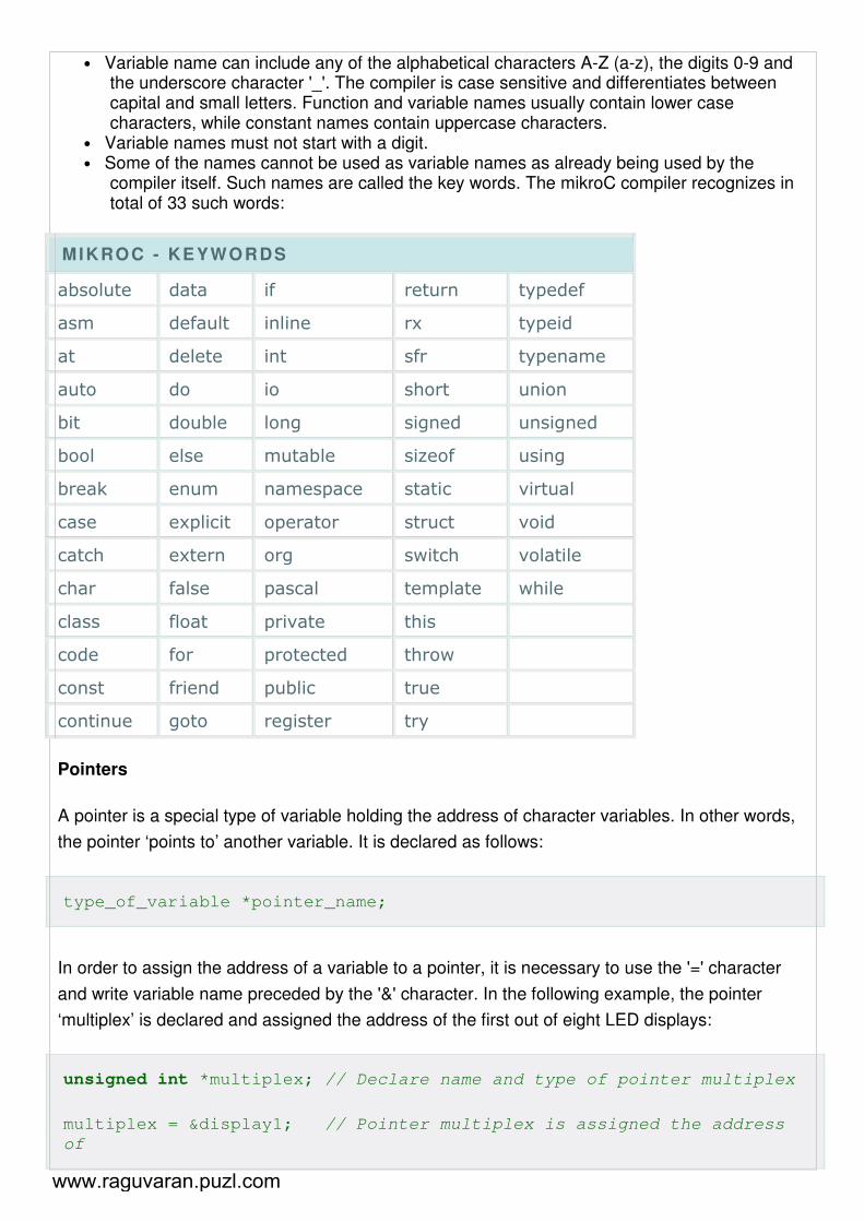
• Variable name can include any of the alphabetical characters A-Z (a-z), the digits 0-9 and the underscore character '_'. The compiler is case sensitive and differentiates between capital and small letters. Function and variable names usually contain lower case characters, while constant names contain uppercase characters.
• Variable names must not start with a digit. • Some of the names cannot be used as variable names as already being used by the
compiler itself. Such names are called the key words. The mikroC compiler recognizes in total of 33 such words:
MIKROC - KEYWORDS
absolute data if return typedef
asm default inline rx typeid
at delete int sfr typename
auto do io short union
bit double long signed unsigned
bool else mutable sizeof using
break enum namespace static virtual
case explicit operator struct void
catch extern org switch volatile
char false pascal template while
class float private this
code for protected throw
const friend public true
continue goto register try
Pointers
A pointer is a special type of variable holding the address of character variables. In other words,
the pointer ‘points to’ another variable. It is declared as follows:
type_of_variable *pointer_name;
In order to assign the address of a variable to a pointer, it is necessary to use the '=' character
and write variable name preceded by the '&' character. In the following example, the pointer
‘multiplex’ is declared and assigned the address of the first out of eight LED displays:
unsigned int *multiplex; // Declare name and type of pointer multiplex
multiplex = &display1; // Pointer multiplex is assigned the address
of
www.raguvaran.puzl.com
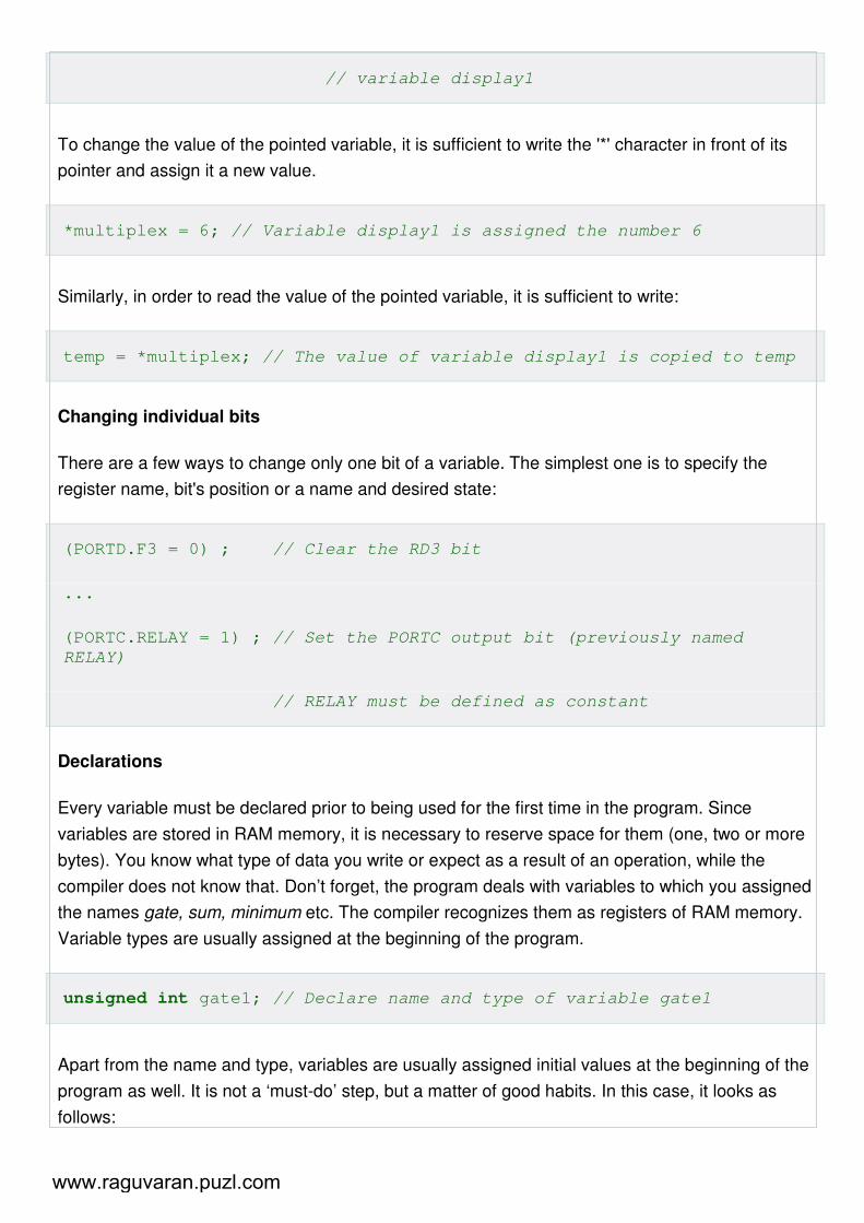
// variable display1
To change the value of the pointed variable, it is sufficient to write the '*' character in front of its
pointer and assign it a new value.
*multiplex = 6; // Variable display1 is assigned the number 6
Similarly, in order to read the value of the pointed variable, it is sufficient to write:
temp = *multiplex; // The value of variable display1 is copied to temp
Changing individual bits
There are a few ways to change only one bit of a variable. The simplest one is to specify the
register name, bit's position or a name and desired state:
(PORTD.F3 = 0) ; // Clear the RD3 bit
...
(PORTC.RELAY = 1) ; // Set the PORTC output bit (previously named
RELAY)
// RELAY must be defined as constant
Declarations
Every variable must be declared prior to being used for the first time in the program. Since
variables are stored in RAM memory, it is necessary to reserve space for them (one, two or more
bytes). You know what type of data you write or expect as a result of an operation, while the
compiler does not know that. Don’t forget, the program deals with variables to which you assigned
the names gate, sum, minimum etc. The compiler recognizes them as registers of RAM memory.
Variable types are usually assigned at the beginning of the program.
unsigned int gate1; // Declare name and type of variable gate1
Apart from the name and type, variables are usually assigned initial values at the beginning of the
program as well. It is not a ‘must-do’ step, but a matter of good habits. In this case, it looks as
follows:
www.raguvaran.puzl.com
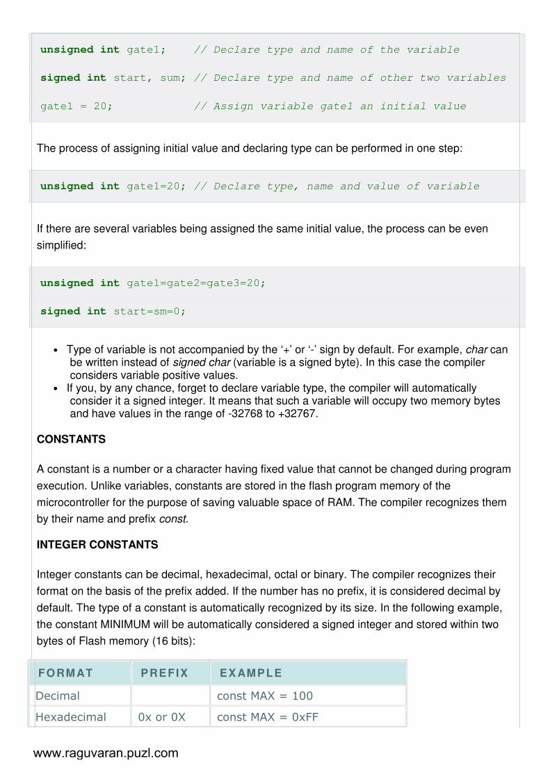
unsigned int gate1; // Declare type and name of the variable
signed int start, sum; // Declare type and name of other two variables
gate1 = 20; // Assign variable gate1 an initial value
The process of assigning initial value and declaring type can be performed in one step:
unsigned int gate1=20; // Declare type, name and value of variable
If there are several variables being assigned the same initial value, the process can be even
simplified:
unsigned int gate1=gate2=gate3=20;
signed int start=sm=0;
• Type of variable is not accompanied by the ‘+’ or ‘-’ sign by default. For example, char can be written instead of signed char (variable is a signed byte). In this case the compiler considers variable positive values.
• If you, by any chance, forget to declare variable type, the compiler will automatically consider it a signed integer. It means that such a variable will occupy two memory bytes and have values in the range of -32768 to +32767.
CONSTANTS
A constant is a number or a character having fixed value that cannot be changed during program
execution. Unlike variables, constants are stored in the flash program memory of the
microcontroller for the purpose of saving valuable space of RAM. The compiler recognizes them
by their name and prefix const.
INTEGER CONSTANTS
Integer constants can be decimal, hexadecimal, octal or binary. The compiler recognizes their
format on the basis of the prefix added. If the number has no prefix, it is considered decimal by
default. The type of a constant is automatically recognized by its size. In the following example,
the constant MINIMUM will be automatically considered a signed integer and stored within two
bytes of Flash memory (16 bits):
FORMAT PREFIX EX AMPLE
Decimal
const MAX = 100
Hexadecimal 0x or 0X const MAX = 0xFF
www.raguvaran.puzl.com
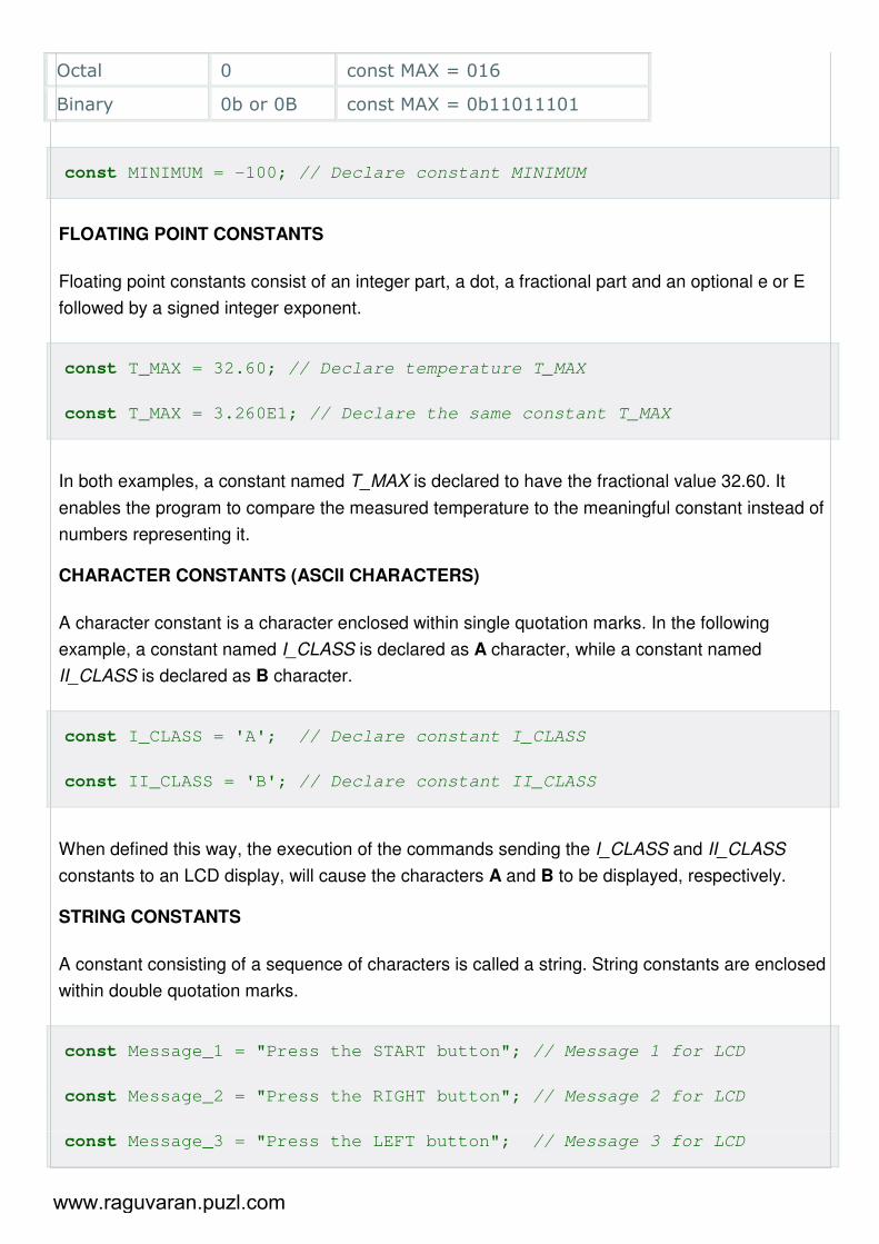
Octal 0 const MAX = 016
Binary 0b or 0B const MAX = 0b11011101
const MINIMUM = -100; // Declare constant MINIMUM
FLOATING POINT CONSTANTS
Floating point constants consist of an integer part, a dot, a fractional part and an optional e or E
followed by a signed integer exponent.
const T_MAX = 32.60; // Declare temperature T_MAX
const T_MAX = 3.260E1; // Declare the same constant T_MAX
In both examples, a constant named T_MAX is declared to have the fractional value 32.60. It
enables the program to compare the measured temperature to the meaningful constant instead of
numbers representing it.
CHARACTER CONSTANTS (ASCII CHARACTERS)
A character constant is a character enclosed within single quotation marks. In the following
example, a constant named I_CLASS is declared as A character, while a constant named
II_CLASS is declared as B character.
const I_CLASS = 'A'; // Declare constant I_CLASS
const II_CLASS = 'B'; // Declare constant II_CLASS
When defined this way, the execution of the commands sending the I_CLASS and II_CLASS
constants to an LCD display, will cause the characters A and B to be displayed, respectively.
STRING CONSTANTS
A constant consisting of a sequence of characters is called a string. String constants are enclosed
within double quotation marks.
const Message_1 = "Press the START button"; // Message 1 for LCD
const Message_2 = "Press the RIGHT button"; // Message 2 for LCD
const Message_3 = "Press the LEFT button"; // Message 3 for LCD
www.raguvaran.puzl.com
In this example, sending the Message_1 constant to an LCD display will cause the message
'press the START button' to be displayed.
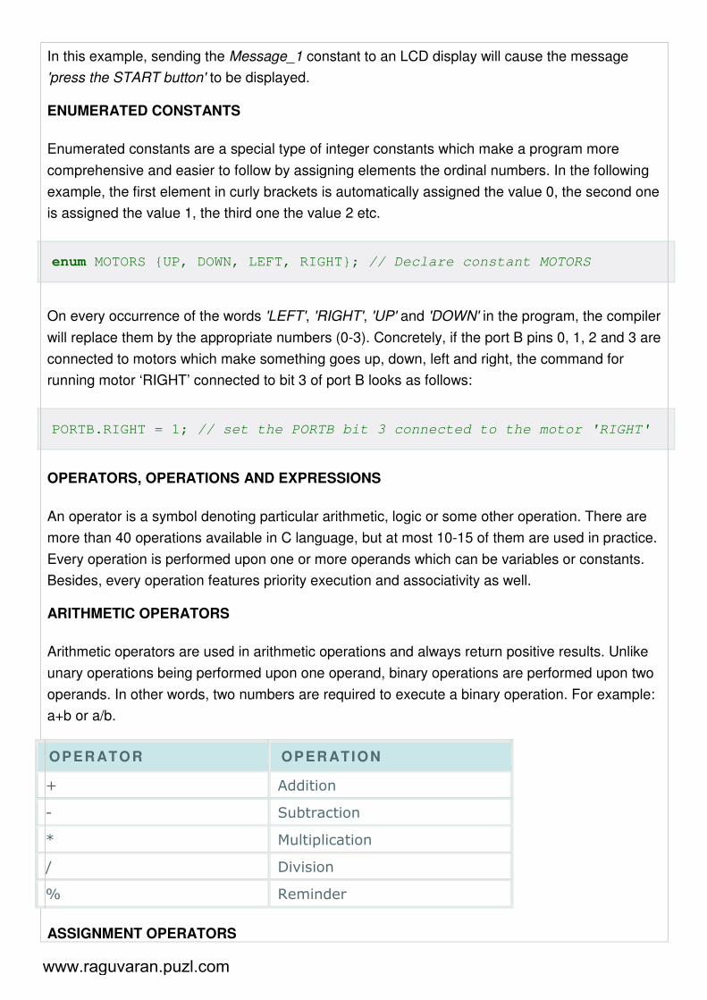
ENUMERATED CONSTANTS
Enumerated constants are a special type of integer constants which make a program more
comprehensive and easier to follow by assigning elements the ordinal numbers. In the following
example, the first element in curly brackets is automatically assigned the value 0, the second one
is assigned the value 1, the third one the value 2 etc.
enum MOTORS UP, DOWN, LEFT, RIGHT; // Declare constant MOTORS
On every occurrence of the words 'LEFT', 'RIGHT', 'UP' and 'DOWN' in the program, the compiler
will replace them by the appropriate numbers (0-3). Concretely, if the port B pins 0, 1, 2 and 3 are
connected to motors which make something goes up, down, left and right, the command for
running motor ‘RIGHT’ connected to bit 3 of port B looks as follows:
PORTB.RIGHT = 1; // set the PORTB bit 3 connected to the motor 'RIGHT'
OPERATORS, OPERATIONS AND EXPRESSIONS
An operator is a symbol denoting particular arithmetic, logic or some other operation. There are
more than 40 operations available in C language, but at most 10-15 of them are used in practice.
Every operation is performed upon one or more operands which can be variables or constants.
Besides, every operation features priority execution and associativity as well.
ARITHMETIC OPERATORS
Arithmetic operators are used in arithmetic operations and always return positive results. Unlike
unary operations being performed upon one operand, binary operations are performed upon two
operands. In other words, two numbers are required to execute a binary operation. For example:
a+b or a/b.
OPERATOR OPERATION
+ Addition
- Subtraction
* Multiplication
/ Division
% Reminder
ASSIGNMENT OPERATORS
www.raguvaran.puzl.com
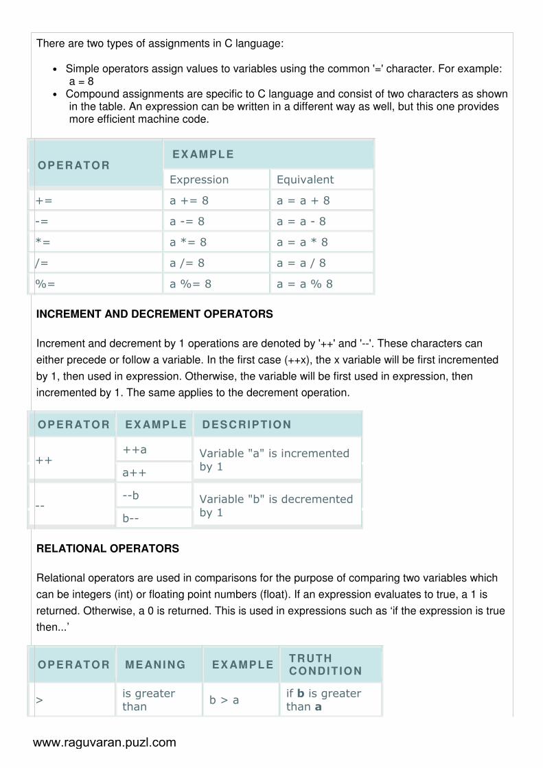
There are two types of assignments in C language:
• Simple operators assign values to variables using the common '=' character. For example: a = 8
• Compound assignments are specific to C language and consist of two characters as shown in the table. An expression can be written in a different way as well, but this one provides more efficient machine code.
OPERATOR EX AMPLE
Expression Equivalent
+= a += 8 a = a + 8
-= a -= 8 a = a - 8
*= a *= 8 a = a * 8
/= a /= 8 a = a / 8
%= a %= 8 a = a % 8
INCREMENT AND DECREMENT OPERATORS
Increment and decrement by 1 operations are denoted by '++' and '--'. These characters can
either precede or follow a variable. In the first case (++x), the x variable will be first incremented
by 1, then used in expression. Otherwise, the variable will be first used in expression, then
incremented by 1. The same applies to the decrement operation.
OPERATOR EX AMPLE DESCRIPTION
++ ++a Variable "a" is incremented
by 1 a++
-- --b Variable "b" is decremented
by 1 b--
RELATIONAL OPERATORS
Relational operators are used in comparisons for the purpose of comparing two variables which
can be integers (int) or floating point numbers (float). If an expression evaluates to true, a 1 is
returned. Otherwise, a 0 is returned. This is used in expressions such as ‘if the expression is true
then...’
OPERATOR ME ANING EX AMPLE TRUTH CONDIT ION
> is greater than
b > a if b is greater than a
www.raguvaran.puzl.com
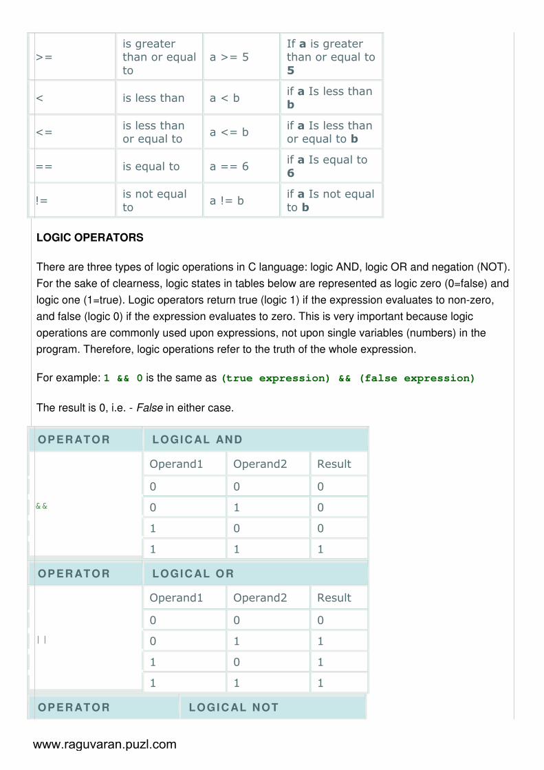
>= is greater than or equal
to
a >= 5 If a is greater than or equal to
5
< is less than a < b if a Is less than b
<= is less than or equal to
a <= b if a Is less than or equal to b
== is equal to a == 6 if a Is equal to
6
!= is not equal
to a != b
if a Is not equal
to b
LOGIC OPERATORS
There are three types of logic operations in C language: logic AND, logic OR and negation (NOT).
For the sake of clearness, logic states in tables below are represented as logic zero (0=false) and
logic one (1=true). Logic operators return true (logic 1) if the expression evaluates to non-zero,
and false (logic 0) if the expression evaluates to zero. This is very important because logic
operations are commonly used upon expressions, not upon single variables (numbers) in the
program. Therefore, logic operations refer to the truth of the whole expression.
For example: 1 && 0 is the same as (true expression) && (false expression)
The result is 0, i.e. - False in either case.
OPERATOR LOGICAL AND
&&
Operand1 Operand2 Result
0 0 0
0 1 0
1 0 0
1 1 1
OPERATOR LOGICAL OR
||
Operand1 Operand2 Result
0 0 0
0 1 1
1 0 1
1 1 1
OPERATOR LOGICAL NOT
www.raguvaran.puzl.com
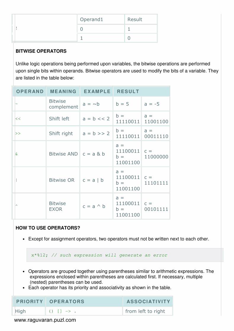
!
Operand1 Result
0 1
1 0
BITWISE OPERATORS
Unlike logic operations being performed upon variables, the bitwise operations are performed
upon single bits within operands. Bitwise operators are used to modify the bits of a variable. They
are listed in the table below:
OPERAND ME ANING EX AMPLE RESULT
~ Bitwise complement
a = ~b b = 5 a = -5
<< Shift left a = b << 2 b =
11110011
a =
11001100
>> Shift right a = b >> 2 b =
11110011
a =
00011110
& Bitwise AND c = a & b
a =
11100011 b =
11001100
c = 11000000
| Bitwise OR c = a | b
a =
11100011 b =
11001100
c = 11101111
^ Bitwise
EXOR c = a ^ b
a = 11100011
b = 11001100
c =
00101111
HOW TO USE OPERATORS?
• Except for assignment operators, two operators must not be written next to each other.
x*%12; // such expression will generate an error
• Operators are grouped together using parentheses similar to arithmetic expressions. The expressions enclosed within parentheses are calculated first. If necessary, multiple (nested) parentheses can be used.
• Each operator has its priority and associativity as shown in the table.
PRIORITY OPERATORS ASSOCI ATIV ITY
High () [] -> . from left to right
www.raguvaran.puzl.com
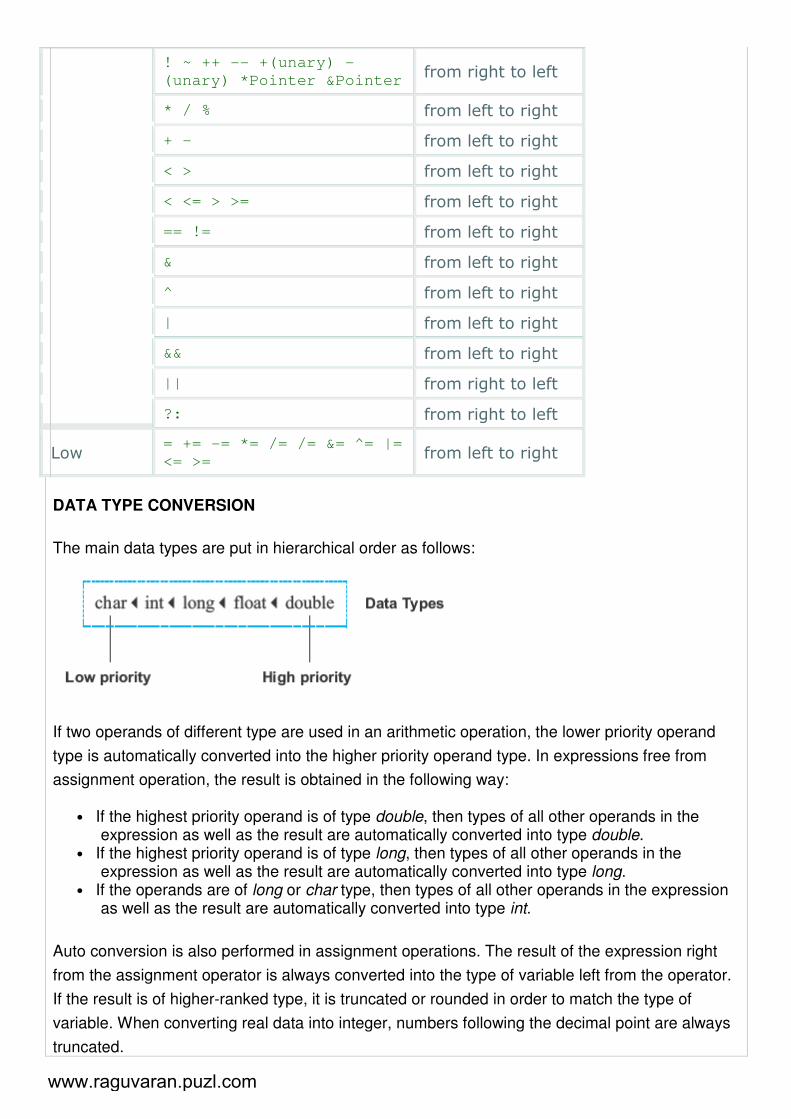
! ~ ++ -- +(unary) -
(unary) *Pointer &Pointer from right to left
* / % from left to right
+ - from left to right
< > from left to right
< <= > >= from left to right
== != from left to right
& from left to right
^ from left to right
| from left to right
&& from left to right
|| from right to left
?: from right to left
Low = += -= *= /= /= &= ^= |=
<= >= from left to right
DATA TYPE CONVERSION
The main data types are put in hierarchical order as follows:
If two operands of different type are used in an arithmetic operation, the lower priority operand
type is automatically converted into the higher priority operand type. In expressions free from
assignment operation, the result is obtained in the following way:
• If the highest priority operand is of type double, then types of all other operands in the expression as well as the result are automatically converted into type double.
• If the highest priority operand is of type long, then types of all other operands in the expression as well as the result are automatically converted into type long.
• If the operands are of long or char type, then types of all other operands in the expression as well as the result are automatically converted into type int.
Auto conversion is also performed in assignment operations. The result of the expression right
from the assignment operator is always converted into the type of variable left from the operator.
If the result is of higher-ranked type, it is truncated or rounded in order to match the type of
variable. When converting real data into integer, numbers following the decimal point are always
truncated.
www.raguvaran.puzl.com
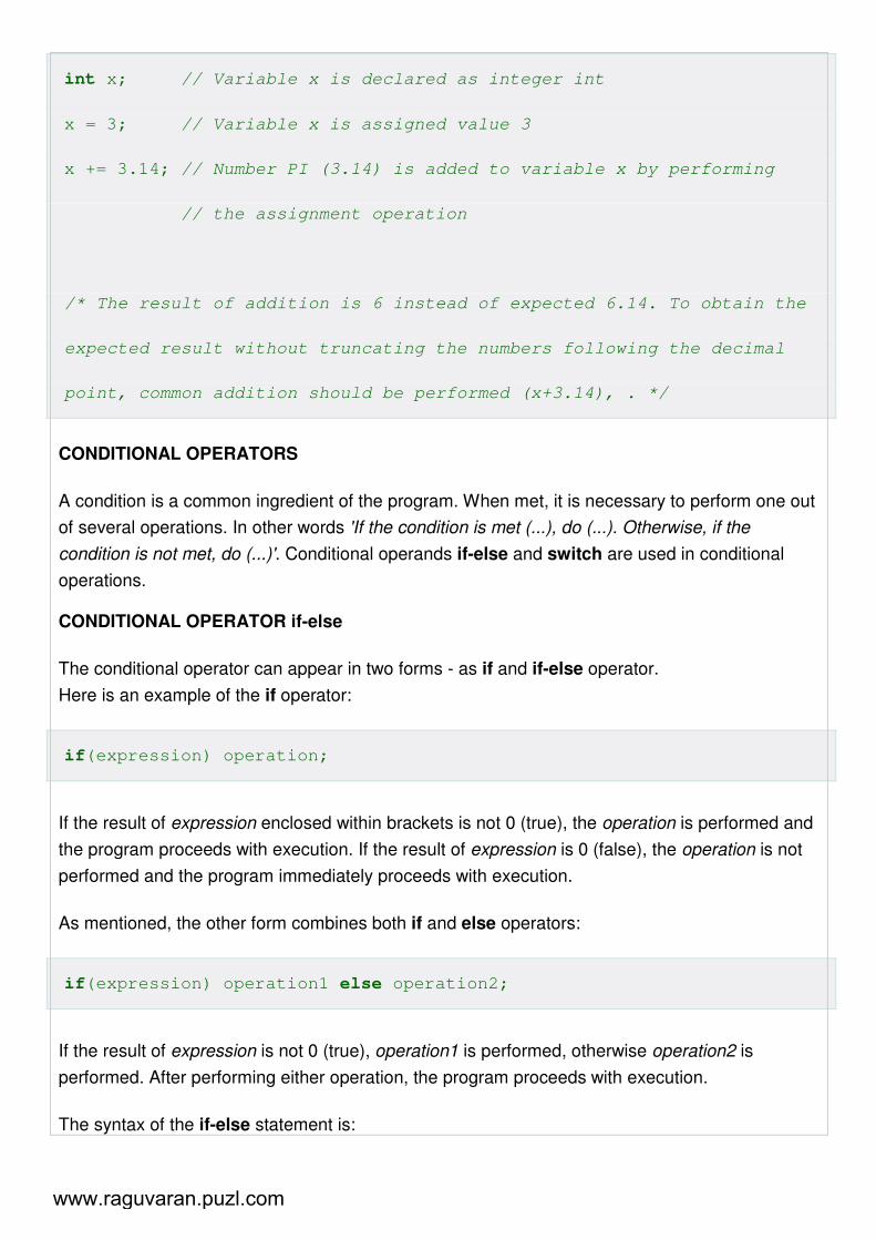
int x; // Variable x is declared as integer int
x = 3; // Variable x is assigned value 3
x += 3.14; // Number PI (3.14) is added to variable x by performing
// the assignment operation
/* The result of addition is 6 instead of expected 6.14. To obtain the
expected result without truncating the numbers following the decimal
point, common addition should be performed (x+3.14), . */
CONDITIONAL OPERATORS
A condition is a common ingredient of the program. When met, it is necessary to perform one out
of several operations. In other words 'If the condition is met (...), do (...). Otherwise, if the
condition is not met, do (...)'. Conditional operands if-else and switch are used in conditional
operations.
CONDITIONAL OPERATOR if-else
The conditional operator can appear in two forms - as if and if-else operator.
Here is an example of the if operator:
if(expression) operation;
If the result of expression enclosed within brackets is not 0 (true), the operation is performed and
the program proceeds with execution. If the result of expression is 0 (false), the operation is not
performed and the program immediately proceeds with execution.
As mentioned, the other form combines both if and else operators:
if(expression) operation1 else operation2;
If the result of expression is not 0 (true), operation1 is performed, otherwise operation2 is
performed. After performing either operation, the program proceeds with execution.
The syntax of the if-else statement is:
www.raguvaran.puzl.com
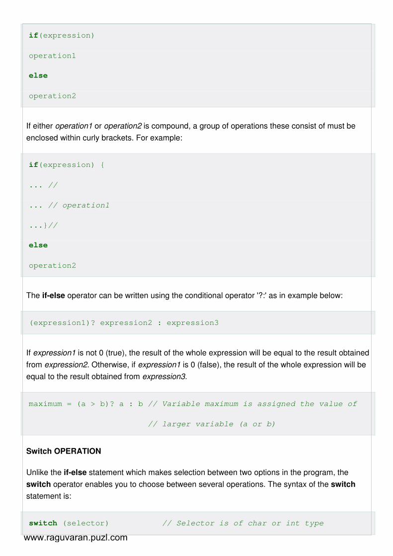
if(expression)
operation1
else
operation2
If either operation1 or operation2 is compound, a group of operations these consist of must be
enclosed within curly brackets. For example:
if(expression)
... //
... // operation1
...//
else
operation2
The if-else operator can be written using the conditional operator '?:' as in example below:
(expression1)? expression2 : expression3
If expression1 is not 0 (true), the result of the whole expression will be equal to the result obtained
from expression2. Otherwise, if expression1 is 0 (false), the result of the whole expression will be
equal to the result obtained from expression3.
maximum = (a > b)? a : b // Variable maximum is assigned the value of
// larger variable (a or b)
Switch OPERATION
Unlike the if-else statement which makes selection between two options in the program, the
switch operator enables you to choose between several operations. The syntax of the switch
statement is:
switch (selector) // Selector is of char or int type
www.raguvaran.puzl.com
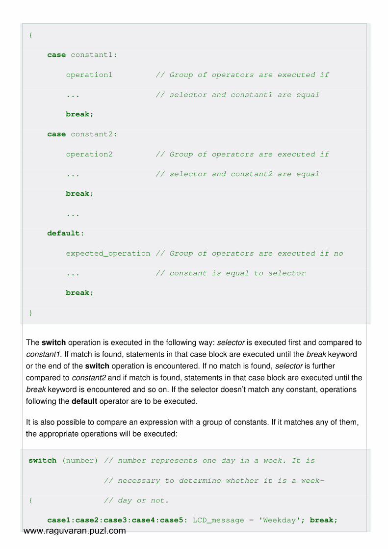
case constant1:
operation1 // Group of operators are executed if
... // selector and constant1 are equal
break;
case constant2:
operation2 // Group of operators are executed if
... // selector and constant2 are equal
break;
...
default:
expected_operation // Group of operators are executed if no
... // constant is equal to selector
break;
The switch operation is executed in the following way: selector is executed first and compared to
constant1. If match is found, statements in that case block are executed until the break keyword
or the end of the switch operation is encountered. If no match is found, selector is further
compared to constant2 and if match is found, statements in that case block are executed until the
break keyword is encountered and so on. If the selector doesn’t match any constant, operations
following the default operator are to be executed.
It is also possible to compare an expression with a group of constants. If it matches any of them,
the appropriate operations will be executed:
switch (number) // number represents one day in a week. It is
// necessary to determine whether it is a week-
// day or not.
case1:case2:case3:case4:case5: LCD_message = 'Weekday'; break;
www.raguvaran.puzl.com
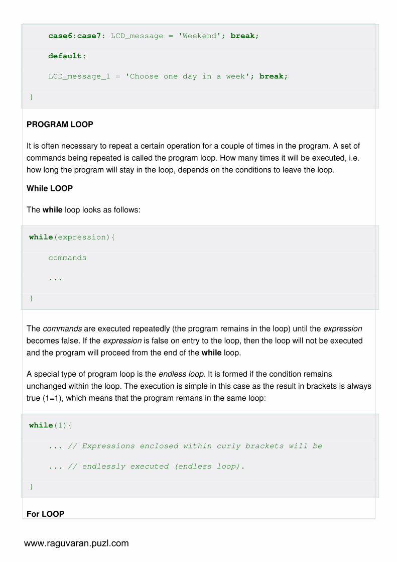
case6:case7: LCD_message = 'Weekend'; break;
default:
LCD_message_1 = 'Choose one day in a week'; break;
PROGRAM LOOP
It is often necessary to repeat a certain operation for a couple of times in the program. A set of
commands being repeated is called the program loop. How many times it will be executed, i.e.
how long the program will stay in the loop, depends on the conditions to leave the loop.
While LOOP
The while loop looks as follows:
while(expression)
commands
...
The commands are executed repeatedly (the program remains in the loop) until the expression
becomes false. If the expression is false on entry to the loop, then the loop will not be executed
and the program will proceed from the end of the while loop.
A special type of program loop is the endless loop. It is formed if the condition remains
unchanged within the loop. The execution is simple in this case as the result in brackets is always
true (1=1), which means that the program remans in the same loop:
while(1)
... // Expressions enclosed within curly brackets will be
... // endlessly executed (endless loop).
For LOOP
www.raguvaran.puzl.com
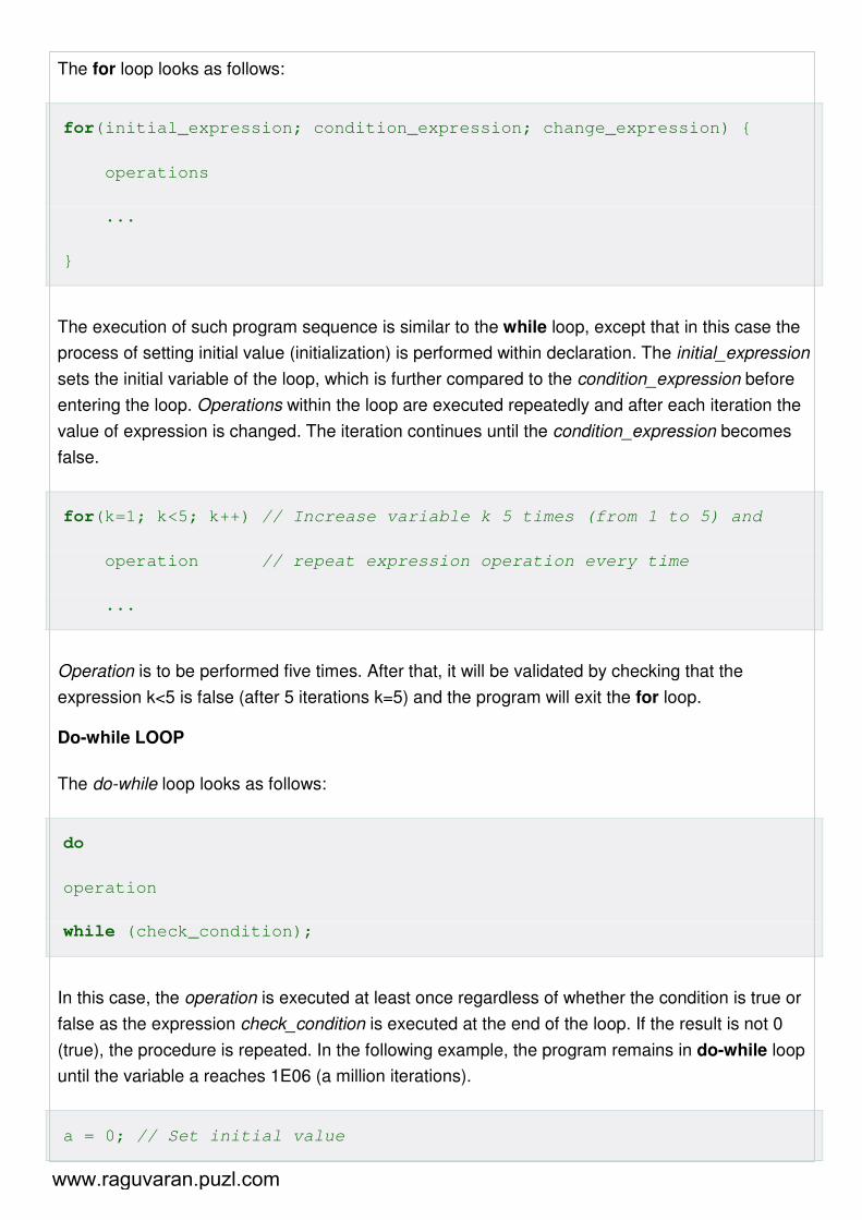
The for loop looks as follows:
for(initial_expression; condition_expression; change_expression)
operations
...
The execution of such program sequence is similar to the while loop, except that in this case the
process of setting initial value (initialization) is performed within declaration. The initial_expression
sets the initial variable of the loop, which is further compared to the condition_expression before
entering the loop. Operations within the loop are executed repeatedly and after each iteration the
value of expression is changed. The iteration continues until the condition_expression becomes
false.
for(k=1; k<5; k++) // Increase variable k 5 times (from 1 to 5) and
operation // repeat expression operation every time
...
Operation is to be performed five times. After that, it will be validated by checking that the
expression k<5 is false (after 5 iterations k=5) and the program will exit the for loop.
Do-while LOOP
The do-while loop looks as follows:
do
operation
while (check_condition);
In this case, the operation is executed at least once regardless of whether the condition is true or
false as the expression check_condition is executed at the end of the loop. If the result is not 0
(true), the procedure is repeated. In the following example, the program remains in do-while loop
until the variable a reaches 1E06 (a million iterations).
a = 0; // Set initial value
www.raguvaran.puzl.com
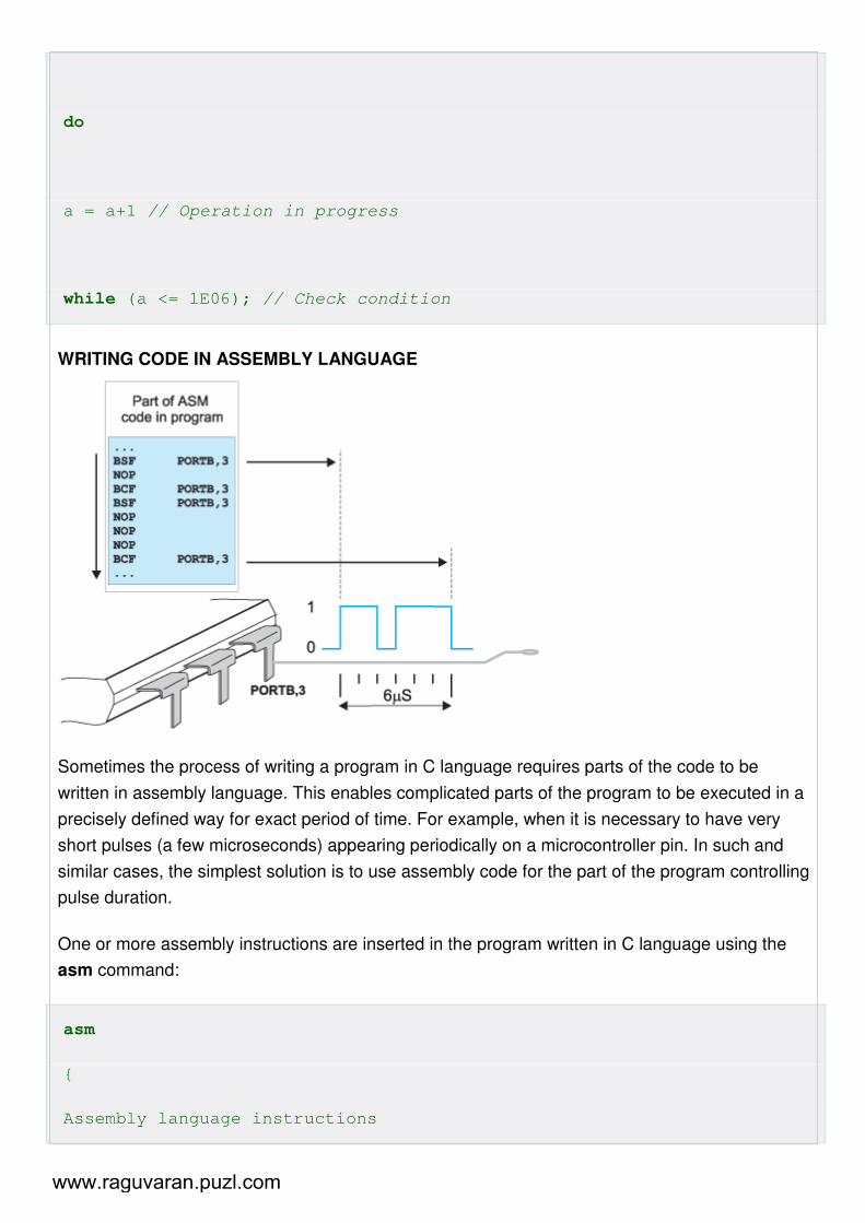
do
a = a+1 // Operation in progress
while (a <= 1E06); // Check condition
WRITING CODE IN ASSEMBLY LANGUAGE
Sometimes the process of writing a program in C language requires parts of the code to be
written in assembly language. This enables complicated parts of the program to be executed in a
precisely defined way for exact period of time. For example, when it is necessary to have very
short pulses (a few microseconds) appearing periodically on a microcontroller pin. In such and
similar cases, the simplest solution is to use assembly code for the part of the program controlling
pulse duration.
One or more assembly instructions are inserted in the program written in C language using the
asm command:
asm
Assembly language instructions
www.raguvaran.puzl.com
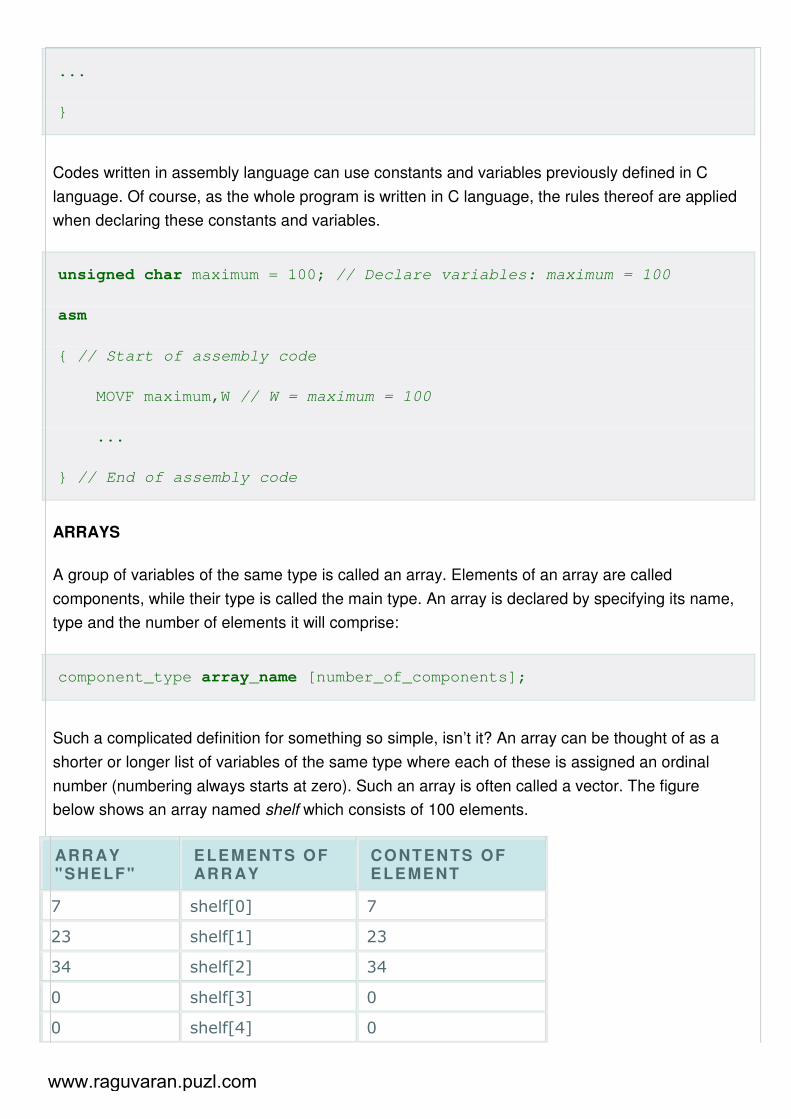
...
Codes written in assembly language can use constants and variables previously defined in C
language. Of course, as the whole program is written in C language, the rules thereof are applied
when declaring these constants and variables.
unsigned char maximum = 100; // Declare variables: maximum = 100
asm
// Start of assembly code
MOVF maximum,W // W = maximum = 100
...
// End of assembly code
ARRAYS
A group of variables of the same type is called an array. Elements of an array are called
components, while their type is called the main type. An array is declared by specifying its name,
type and the number of elements it will comprise:
component_type array_name [number_of_components];
Such a complicated definition for something so simple, isn’t it? An array can be thought of as a
shorter or longer list of variables of the same type where each of these is assigned an ordinal
number (numbering always starts at zero). Such an array is often called a vector. The figure
below shows an array named shelf which consists of 100 elements.
ARR AY "SHELF"
ELEMENTS OF ARR AY
CONTENTS OF ELEMENT
7 shelf[0] 7
23 shelf[1] 23
34 shelf[2] 34
0 shelf[3] 0
0 shelf[4] 0
www.raguvaran.puzl.com
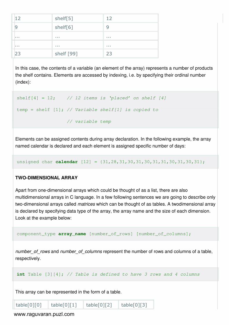
12 shelf[5] 12
9 shelf[6] 9
... ... ...
... ... ...
23 shelf [99] 23
In this case, the contents of a variable (an element of the array) represents a number of products
the shelf contains. Elements are accessed by indexing, i.e. by specifying their ordinal number
(index):
shelf[4] = 12; // 12 items is ‘placed’ on shelf [4]
temp = shelf [1]; // Variable shelf[1] is copied to
// variable temp
Elements can be assigned contents during array declaration. In the following example, the array
named calendar is declared and each element is assigned specific number of days:
unsigned char calendar [12] = 31,28,31,30,31,30,31,31,30,31,30,31;
TWO-DIMENSIONAL ARRAY
Apart from one-dimensional arrays which could be thought of as a list, there are also
multidimensional arrays in C language. In a few following sentences we are going to describe only
two-dimensional arrays called matrices which can be thought of as tables. A twodimensional array
is declared by specifying data type of the array, the array name and the size of each dimension.
Look at the example below:
component_type array_name [number_of_rows] [number_of_columns];
number_of_rows and number_of_columns represent the number of rows and columns of a table,
respectively.
int Table [3][4]; // Table is defined to have 3 rows and 4 columns
This array can be represented in the form of a table.
table[0][0] table[0][1] table[0][2] table[0][3]
www.raguvaran.puzl.com
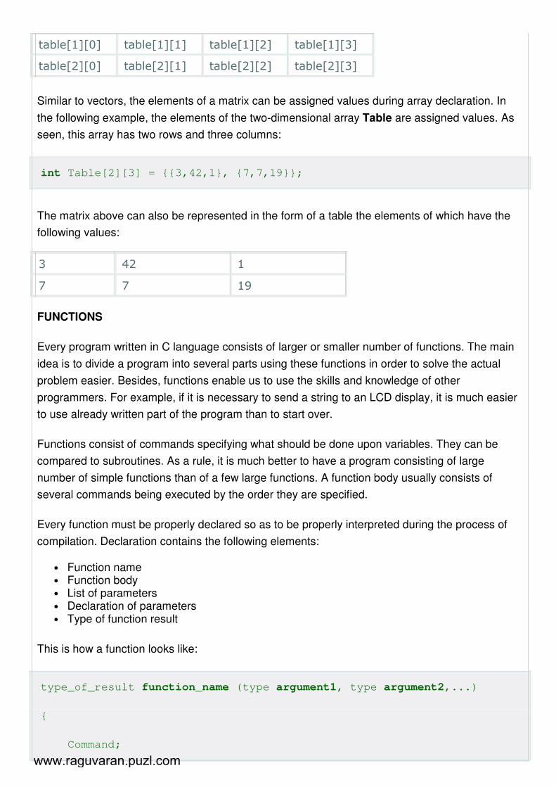
table[1][0] table[1][1] table[1][2] table[1][3]
table[2][0] table[2][1] table[2][2] table[2][3]
Similar to vectors, the elements of a matrix can be assigned values during array declaration. In
the following example, the elements of the two-dimensional array Table are assigned values. As
seen, this array has two rows and three columns:
int Table[2][3] = 3,42,1, 7,7,19;
The matrix above can also be represented in the form of a table the elements of which have the
following values:
3 42 1
7 7 19
FUNCTIONS
Every program written in C language consists of larger or smaller number of functions. The main
idea is to divide a program into several parts using these functions in order to solve the actual
problem easier. Besides, functions enable us to use the skills and knowledge of other
programmers. For example, if it is necessary to send a string to an LCD display, it is much easier
to use already written part of the program than to start over.
Functions consist of commands specifying what should be done upon variables. They can be
compared to subroutines. As a rule, it is much better to have a program consisting of large
number of simple functions than of a few large functions. A function body usually consists of
several commands being executed by the order they are specified.
Every function must be properly declared so as to be properly interpreted during the process of
compilation. Declaration contains the following elements:
• Function name • Function body • List of parameters • Declaration of parameters • Type of function result
This is how a function looks like:
type_of_result function_name (type argument1, type argument2,...)
Command;
www.raguvaran.puzl.com
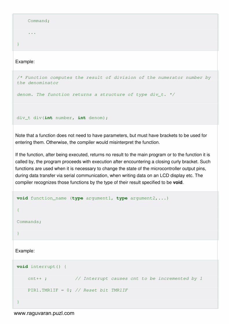
Command;
...
Example:
/* Function computes the result of division of the numerator number by
the denominator
denom. The function returns a structure of type div_t. */
div_t div(int number, int denom);
Note that a function does not need to have parameters, but must have brackets to be used for
entering them. Otherwise, the compiler would misinterpret the function.
If the function, after being executed, returns no result to the main program or to the function it is
called by, the program proceeds with execution after encountering a closing curly bracket. Such
functions are used when it is necessary to change the state of the microcontroller output pins,
during data transfer via serial communication, when writing data on an LCD display etc. The
compiler recognizes those functions by the type of their result specified to be void.
void function_name (type argument1, type argument2,...)
Commands;
Example:
void interrupt()
cnt++ ; // Interrupt causes cnt to be incremented by 1
PIR1.TMR1IF = 0; // Reset bit TMR1IF
www.raguvaran.puzl.com
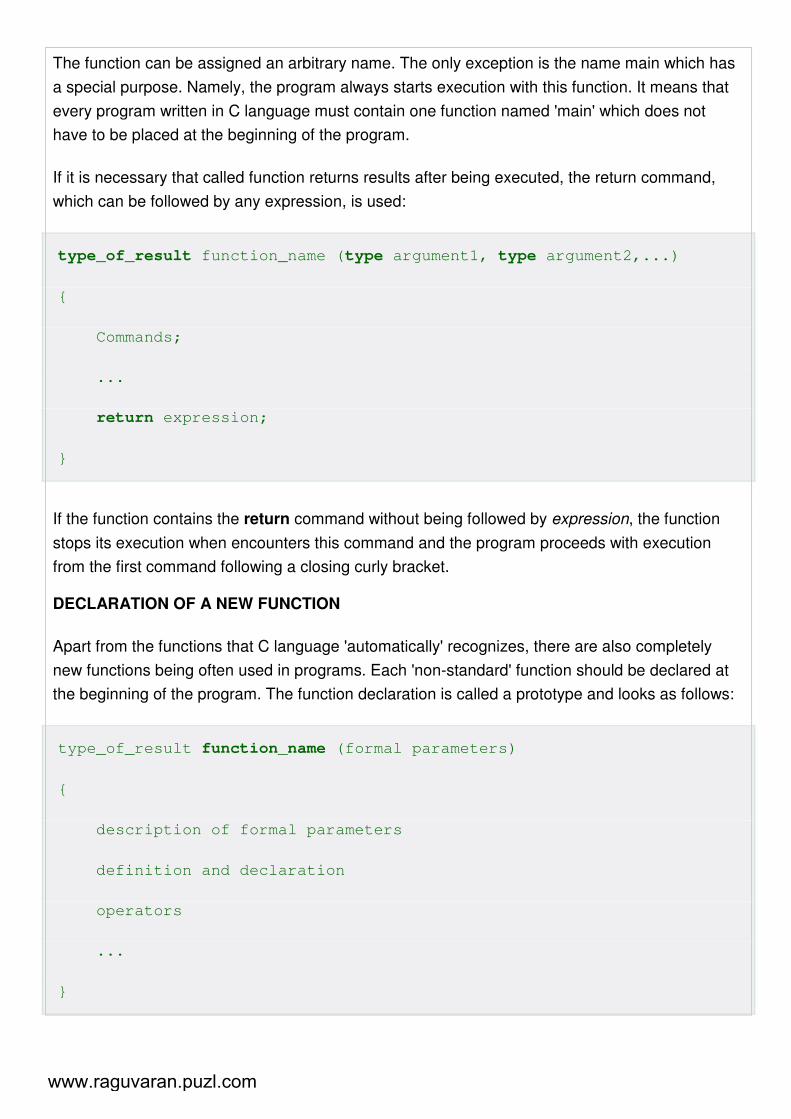
The function can be assigned an arbitrary name. The only exception is the name main which has
a special purpose. Namely, the program always starts execution with this function. It means that
every program written in C language must contain one function named 'main' which does not
have to be placed at the beginning of the program.
If it is necessary that called function returns results after being executed, the return command,
which can be followed by any expression, is used:
type_of_result function_name (type argument1, type argument2,...)
Commands;
...
return expression;
If the function contains the return command without being followed by expression, the function
stops its execution when encounters this command and the program proceeds with execution
from the first command following a closing curly bracket.
DECLARATION OF A NEW FUNCTION
Apart from the functions that C language 'automatically' recognizes, there are also completely
new functions being often used in programs. Each 'non-standard' function should be declared at
the beginning of the program. The function declaration is called a prototype and looks as follows:
type_of_result function_name (formal parameters)
description of formal parameters
definition and declaration
operators
...
www.raguvaran.puzl.com
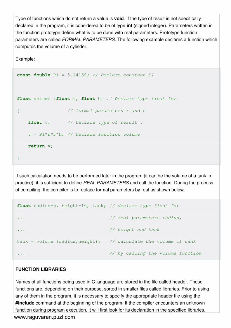
Type of functions which do not return a value is void. If the type of result is not specifically
declared in the program, it is considered to be of type int (signed integer). Parameters written in
the function prototype define what is to be done with real parameters. Prototype function
parameters are called FORMAL PARAMETERS. The following example declares a function which
computes the volume of a cylinder.
Example:
const double PI = 3.14159; // Declare constant PI
float volume (float r, float h) // Declare type float for
// formal parameters r and h
float v; // Declare type of result v
v = PI*r*r*h; // Declare function volume
return v;
If such calculation needs to be performed later in the program (it can be the volume of a tank in
practice), it is sufficient to define REAL PARAMETERS and call the function. During the process
of compiling, the compiler is to replace formal parameters by real as shown below:
float radius=5, height=10, tank; // declare type float for
... // real parameters radius,
... // height and tank
tank = volume (radius,height); // calculate the volume of tank
... // by calling the volume function
FUNCTION LIBRARIES
Names of all functions being used in C language are stored in the file called header. These
functions are, depending on their purpose, sorted in smaller files called libraries. Prior to using
any of them in the program, it is necessary to specify the appropriate header file using the
#include command at the beginning of the program. If the compiler encounters an unknown
function during program execution, it will first look for its declaration in the specified libraries.
www.raguvaran.puzl.com
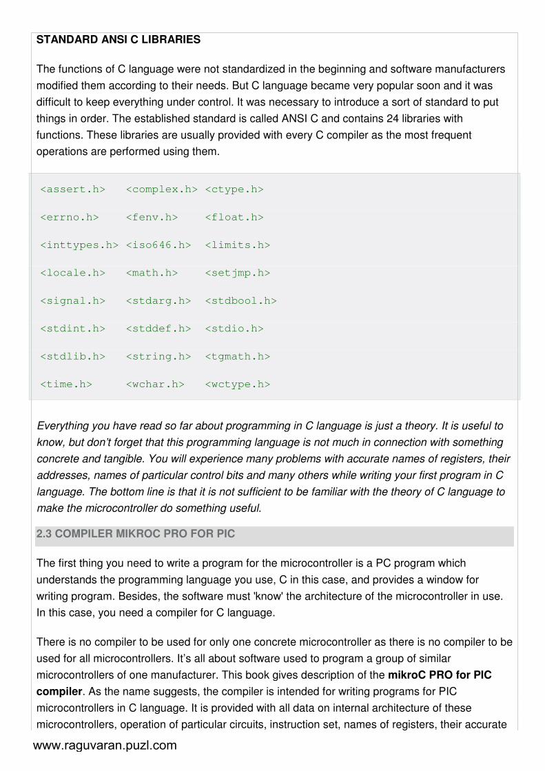
STANDARD ANSI C LIBRARIES
The functions of C language were not standardized in the beginning and software manufacturers
modified them according to their needs. But C language became very popular soon and it was
difficult to keep everything under control. It was necessary to introduce a sort of standard to put
things in order. The established standard is called ANSI C and contains 24 libraries with
functions. These libraries are usually provided with every C compiler as the most frequent
operations are performed using them.
<assert.h> <complex.h> <ctype.h>
<errno.h> <fenv.h> <float.h>
<inttypes.h> <iso646.h> <limits.h>
<locale.h> <math.h> <setjmp.h>
<signal.h> <stdarg.h> <stdbool.h>
<stdint.h> <stddef.h> <stdio.h>
<stdlib.h> <string.h> <tgmath.h>
<time.h> <wchar.h> <wctype.h>
Everything you have read so far about programming in C language is just a theory. It is useful to
know, but don’t forget that this programming language is not much in connection with something
concrete and tangible. You will experience many problems with accurate names of registers, their
addresses, names of particular control bits and many others while writing your first program in C
language. The bottom line is that it is not sufficient to be familiar with the theory of C language to
make the microcontroller do something useful.
2.3 COMPILER MIKROC PRO FOR PIC
The first thing you need to write a program for the microcontroller is a PC program which
understands the programming language you use, C in this case, and provides a window for
writing program. Besides, the software must 'know' the architecture of the microcontroller in use.
In this case, you need a compiler for C language.
There is no compiler to be used for only one concrete microcontroller as there is no compiler to be
used for all microcontrollers. It’s all about software used to program a group of similar
microcontrollers of one manufacturer. This book gives description of the mikroC PRO for PIC
compiler. As the name suggests, the compiler is intended for writing programs for PIC
microcontrollers in C language. It is provided with all data on internal architecture of these
microcontrollers, operation of particular circuits, instruction set, names of registers, their accurate
www.raguvaran.puzl.com
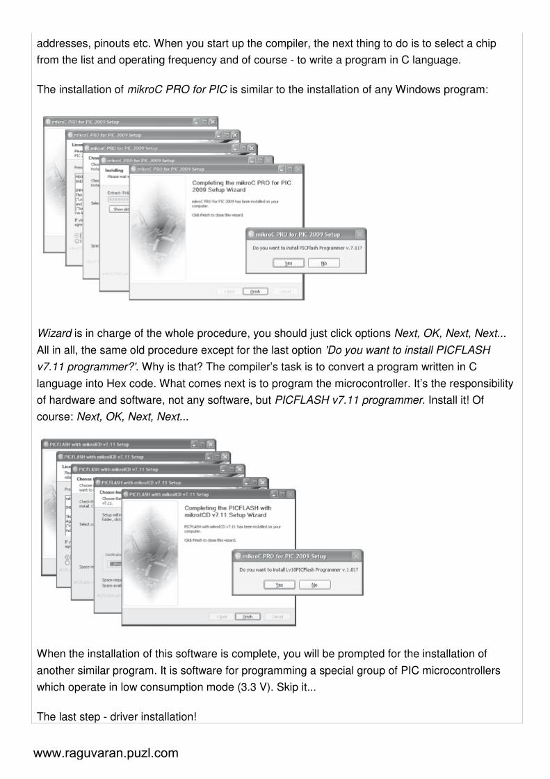
addresses, pinouts etc. When you start up the compiler, the next thing to do is to select a chip
from the list and operating frequency and of course - to write a program in C language.
The installation of mikroC PRO for PIC is similar to the installation of any Windows program:
Wizard is in charge of the whole procedure, you should just click options Next, OK, Next, Next...
All in all, the same old procedure except for the last option 'Do you want to install PICFLASH
v7.11 programmer?'. Why is that? The compiler’s task is to convert a program written in C
language into Hex code. What comes next is to program the microcontroller. It’s the responsibility
of hardware and software, not any software, but PICFLASH v7.11 programmer. Install it! Of
course: Next, OK, Next, Next...
When the installation of this software is complete, you will be prompted for the installation of
another similar program. It is software for programming a special group of PIC microcontrollers
which operate in low consumption mode (3.3 V). Skip it...
The last step - driver installation!
www.raguvaran.puzl.com
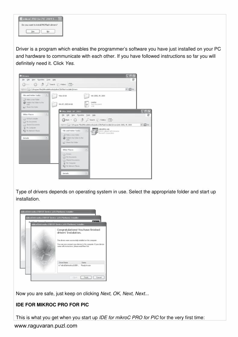
Driver is a program which enables the programmer’s software you have just installed on your PC
and hardware to communicate with each other. If you have followed instructions so far you will
definitely need it. Click Yes.
Type of drivers depends on operating system in use. Select the appropriate folder and start up
installation.
Now you are safe, just keep on clicking Next, OK, Next, Next...
IDE FOR MIKROC PRO FOR PIC
This is what you get when you start up IDE for mikroC PRO for PIC for the very first time:
www.raguvaran.puzl.com
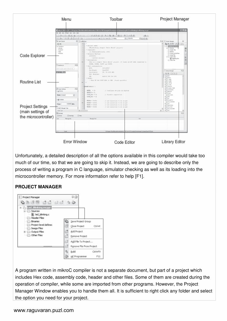
Unfortunately, a detailed description of all the options available in this compiler would take too
much of our time, so that we are going to skip it. Instead, we are going to describe only the
process of writing a program in C language, simulator checking as well as its loading into the
microcontroller memory. For more information refer to help [F1].
PROJECT MANAGER
A program written in mikroC compiler is not a separate document, but part of a project which
includes Hex code, assembly code, header and other files. Some of them are created during the
operation of compiler, while some are imported from other programs. However, the Project
Manager Window enables you to handle them all. It is sufficient to right click any folder and select
the option you need for your project.
www.raguvaran.puzl.com
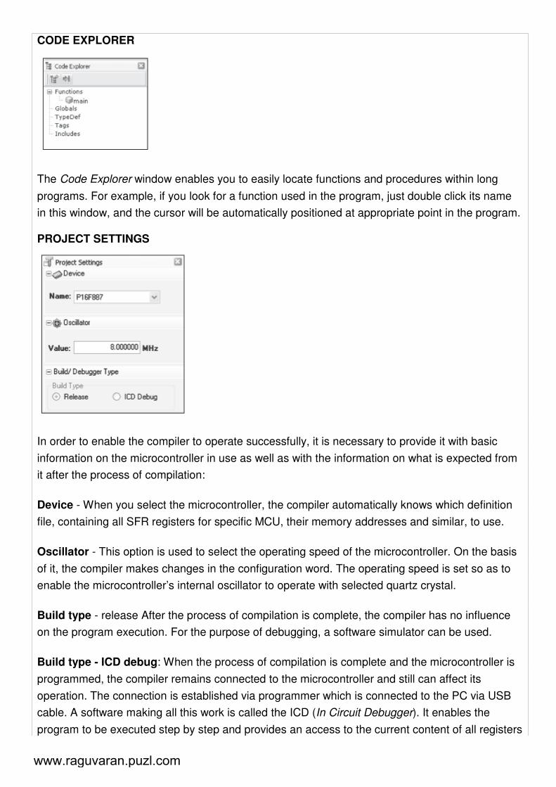
CODE EXPLORER
The Code Explorer window enables you to easily locate functions and procedures within long
programs. For example, if you look for a function used in the program, just double click its name
in this window, and the cursor will be automatically positioned at appropriate point in the program.
PROJECT SETTINGS
In order to enable the compiler to operate successfully, it is necessary to provide it with basic
information on the microcontroller in use as well as with the information on what is expected from
it after the process of compilation:
Device - When you select the microcontroller, the compiler automatically knows which definition
file, containing all SFR registers for specific MCU, their memory addresses and similar, to use.
Oscillator - This option is used to select the operating speed of the microcontroller. On the basis
of it, the compiler makes changes in the configuration word. The operating speed is set so as to
enable the microcontroller’s internal oscillator to operate with selected quartz crystal.
Build type - release After the process of compilation is complete, the compiler has no influence
on the program execution. For the purpose of debugging, a software simulator can be used.
Build type - ICD debug: When the process of compilation is complete and the microcontroller is
programmed, the compiler remains connected to the microcontroller and still can affect its
operation. The connection is established via programmer which is connected to the PC via USB
cable. A software making all this work is called the ICD (In Circuit Debugger). It enables the
program to be executed step by step and provides an access to the current content of all registers
www.raguvaran.puzl.com
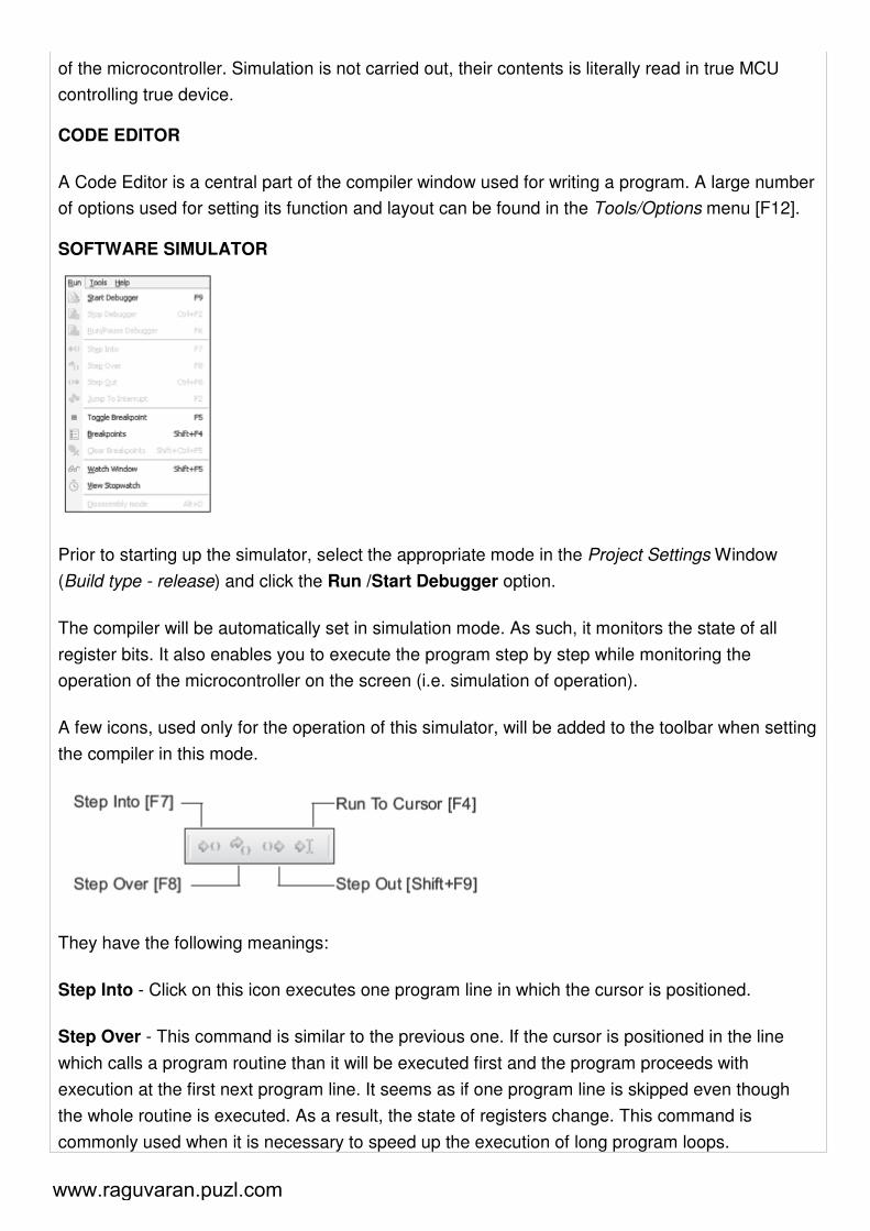
of the microcontroller. Simulation is not carried out, their contents is literally read in true MCU
controlling true device.
CODE EDITOR
A Code Editor is a central part of the compiler window used for writing a program. A large number
of options used for setting its function and layout can be found in the Tools/Options menu [F12].
SOFTWARE SIMULATOR
Prior to starting up the simulator, select the appropriate mode in the Project Settings Window
(Build type - release) and click the Run /Start Debugger option.
The compiler will be automatically set in simulation mode. As such, it monitors the state of all
register bits. It also enables you to execute the program step by step while monitoring the
operation of the microcontroller on the screen (i.e. simulation of operation).
A few icons, used only for the operation of this simulator, will be added to the toolbar when setting
the compiler in this mode.
They have the following meanings:
Step Into - Click on this icon executes one program line in which the cursor is positioned.
Step Over - This command is similar to the previous one. If the cursor is positioned in the line
which calls a program routine than it will be executed first and the program proceeds with
execution at the first next program line. It seems as if one program line is skipped even though
the whole routine is executed. As a result, the state of registers change. This command is
commonly used when it is necessary to speed up the execution of long program loops.
www.raguvaran.puzl.com
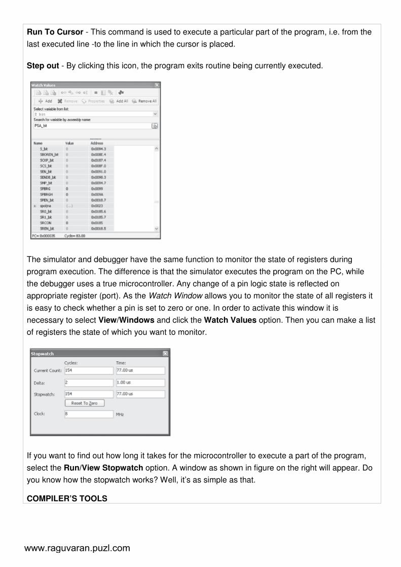
Run To Cursor - This command is used to execute a particular part of the program, i.e. from the
last executed line -to the line in which the cursor is placed.
Step out - By clicking this icon, the program exits routine being currently executed.
The simulator and debugger have the same function to monitor the state of registers during
program execution. The difference is that the simulator executes the program on the PC, while
the debugger uses a true microcontroller. Any change of a pin logic state is reflected on
appropriate register (port). As the Watch Window allows you to monitor the state of all registers it
is easy to check whether a pin is set to zero or one. In order to activate this window it is
necessary to select View/Windows and click the Watch Values option. Then you can make a list
of registers the state of which you want to monitor.
If you want to find out how long it takes for the microcontroller to execute a part of the program,
select the Run/View Stopwatch option. A window as shown in figure on the right will appear. Do
you know how the stopwatch works? Well, it’s as simple as that.
COMPILER’S TOOLS
www.raguvaran.puzl.com
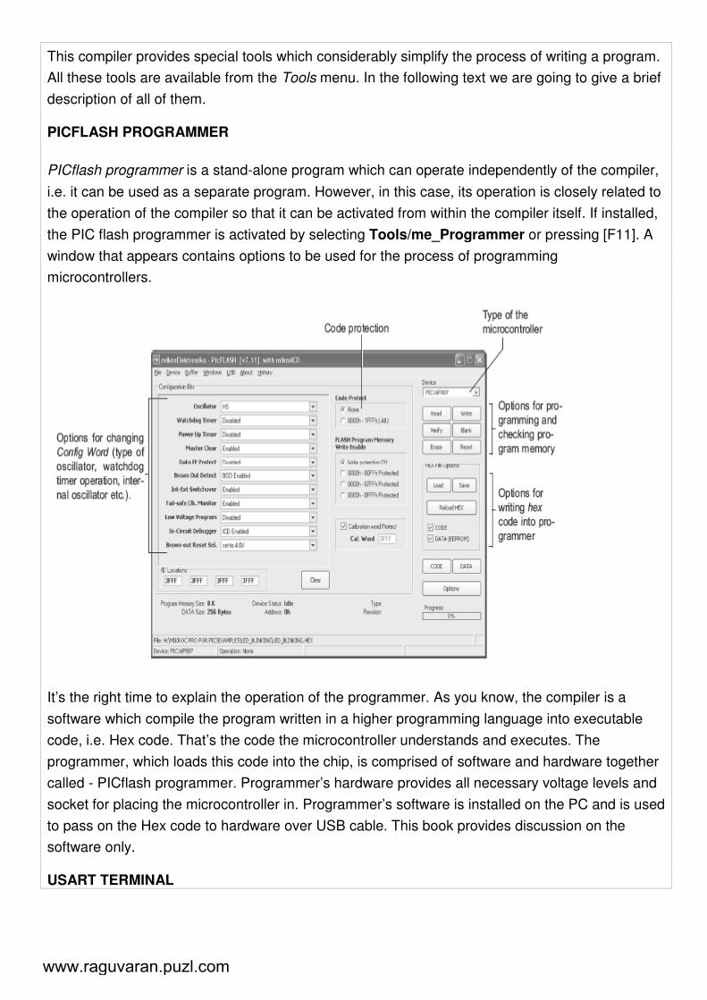
This compiler provides special tools which considerably simplify the process of writing a program.
All these tools are available from the Tools menu. In the following text we are going to give a brief
description of all of them.
PICFLASH PROGRAMMER
PICflash programmer is a stand-alone program which can operate independently of the compiler,
i.e. it can be used as a separate program. However, in this case, its operation is closely related to
the operation of the compiler so that it can be activated from within the compiler itself. If installed,
the PIC flash programmer is activated by selecting Tools/me_Programmer or pressing [F11]. A
window that appears contains options to be used for the process of programming
microcontrollers.
It’s the right time to explain the operation of the programmer. As you know, the compiler is a
software which compile the program written in a higher programming language into executable
code, i.e. Hex code. That’s the code the microcontroller understands and executes. The
programmer, which loads this code into the chip, is comprised of software and hardware together
called - PICflash programmer. Programmer’s hardware provides all necessary voltage levels and
socket for placing the microcontroller in. Programmer’s software is installed on the PC and is used
to pass on the Hex code to hardware over USB cable. This book provides discussion on the
software only.
USART TERMINAL
www.raguvaran.puzl.com
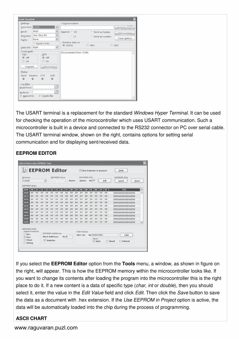
The USART terminal is a replacement for the standard Windows Hyper Terminal. It can be used
for checking the operation of the microcontroller which uses USART communication. Such a
microcontroller is built in a device and connected to the RS232 connector on PC over serial cable.
The USART terminal window, shown on the right, contains options for setting serial
communication and for displaying sent/received data.
EEPROM EDITOR
If you select the EEPROM Editor option from the Tools menu, a window, as shown in figure on
the right, will appear. This is how the EEPROM memory within the microcontroller looks like. If
you want to change its contents after loading the program into the microcontroller this is the right
place to do it. If a new content is a data of specific type (char, int or double), then you should
select it, enter the value in the Edit Value field and click Edit. Then click the Save button to save
the data as a document with .hex extension. If the Use EEPROM in Project option is active, the
data will be automatically loaded into the chip during the process of programming.
ASCII CHART
www.raguvaran.puzl.com
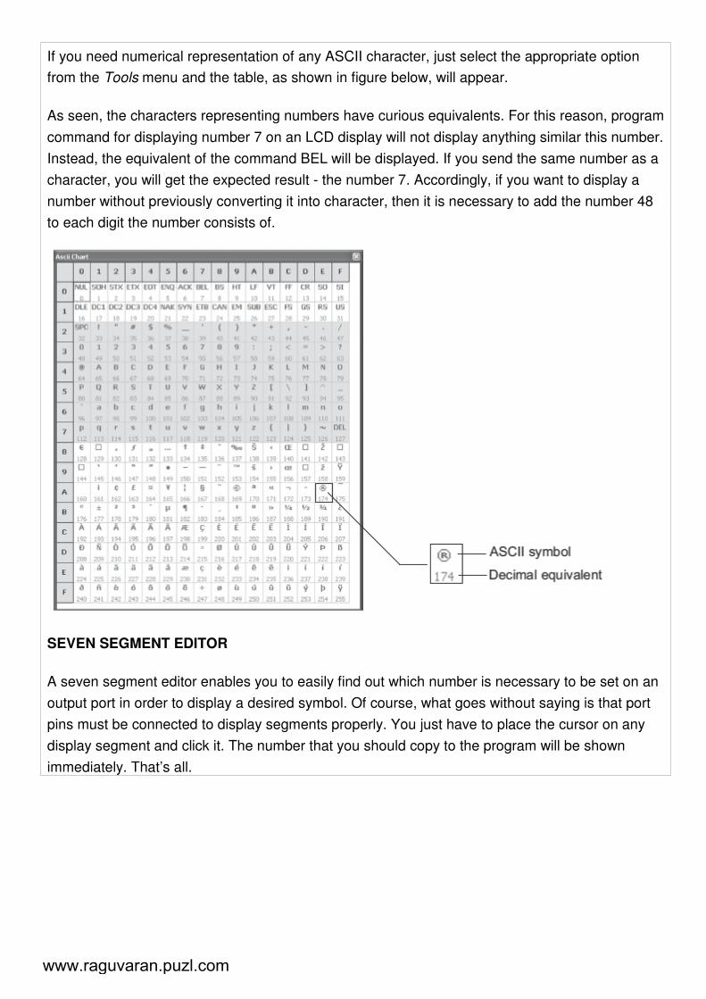
If you need numerical representation of any ASCII character, just select the appropriate option
from the Tools menu and the table, as shown in figure below, will appear.
As seen, the characters representing numbers have curious equivalents. For this reason, program
command for displaying number 7 on an LCD display will not display anything similar this number.
Instead, the equivalent of the command BEL will be displayed. If you send the same number as a
character, you will get the expected result - the number 7. Accordingly, if you want to display a
number without previously converting it into character, then it is necessary to add the number 48
to each digit the number consists of.
SEVEN SEGMENT EDITOR
A seven segment editor enables you to easily find out which number is necessary to be set on an
output port in order to display a desired symbol. Of course, what goes without saying is that port
pins must be connected to display segments properly. You just have to place the cursor on any
display segment and click it. The number that you should copy to the program will be shown
immediately. That’s all.
www.raguvaran.puzl.com
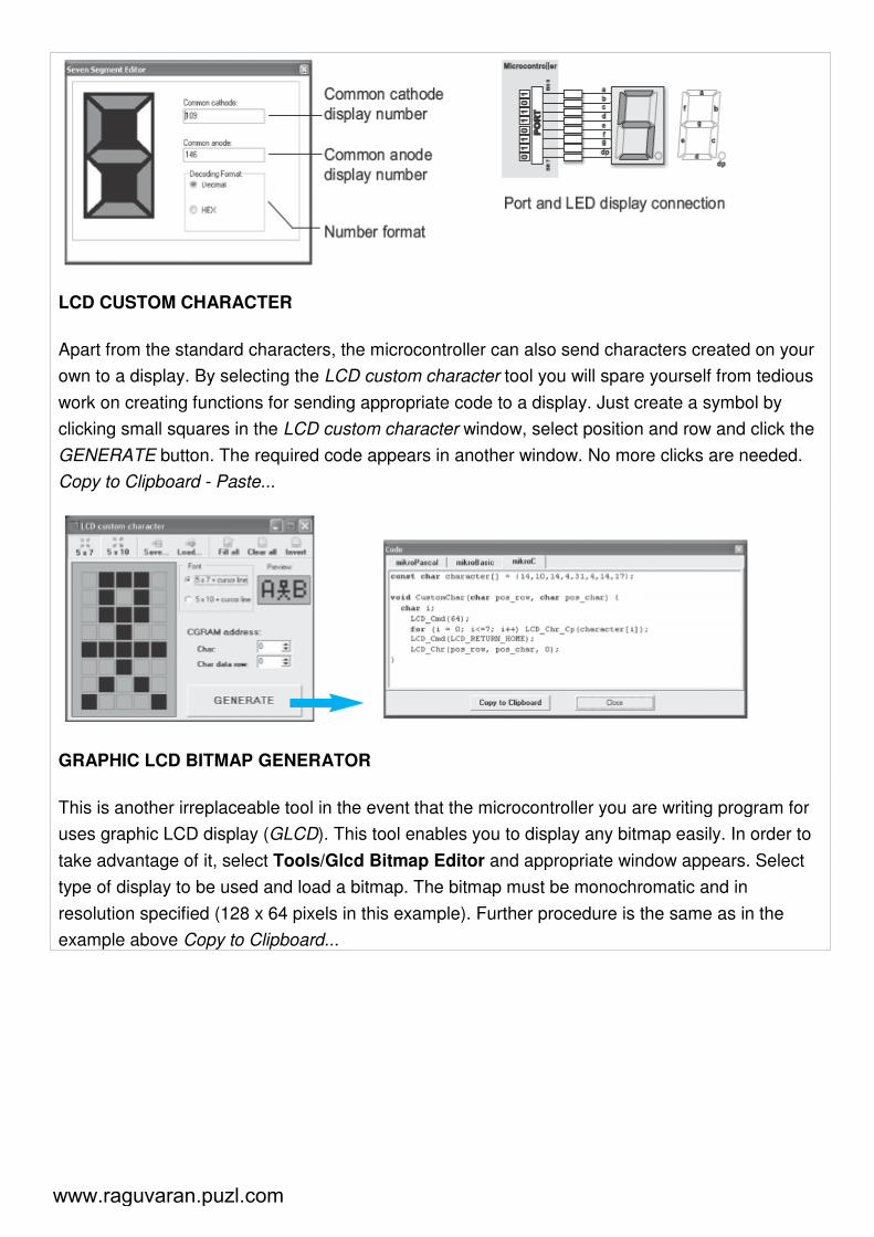
LCD CUSTOM CHARACTER
Apart from the standard characters, the microcontroller can also send characters created on your
own to a display. By selecting the LCD custom character tool you will spare yourself from tedious
work on creating functions for sending appropriate code to a display. Just create a symbol by
clicking small squares in the LCD custom character window, select position and row and click the
GENERATE button. The required code appears in another window. No more clicks are needed.
Copy to Clipboard - Paste...
GRAPHIC LCD BITMAP GENERATOR
This is another irreplaceable tool in the event that the microcontroller you are writing program for
uses graphic LCD display (GLCD). This tool enables you to display any bitmap easily. In order to
take advantage of it, select Tools/Glcd Bitmap Editor and appropriate window appears. Select
type of display to be used and load a bitmap. The bitmap must be monochromatic and in
resolution specified (128 x 64 pixels in this example). Further procedure is the same as in the
example above Copy to Clipboard...
www.raguvaran.puzl.com
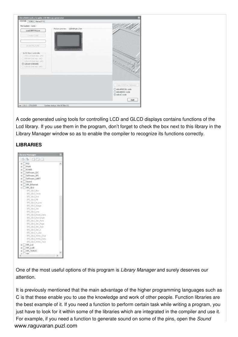
A code generated using tools for controlling LCD and GLCD displays contains functions of the
Lcd library. If you use them in the program, don’t forget to check the box next to this library in the
Library Manager window so as to enable the compiler to recognize its functions correctly.
LIBRARIES
One of the most useful options of this program is Library Manager and surely deserves our
attention.
It is previously mentioned that the main advantage of the higher programming languages such as
C is that these enable you to use the knowledge and work of other people. Function libraries are
the best example of it. If you need a function to perform certain task while writing a program, you
just have to look for it within some of the libraries which are integrated in the compiler and use it.
For example, if you need a function to generate sound on some of the pins, open the Sound
www.raguvaran.puzl.com
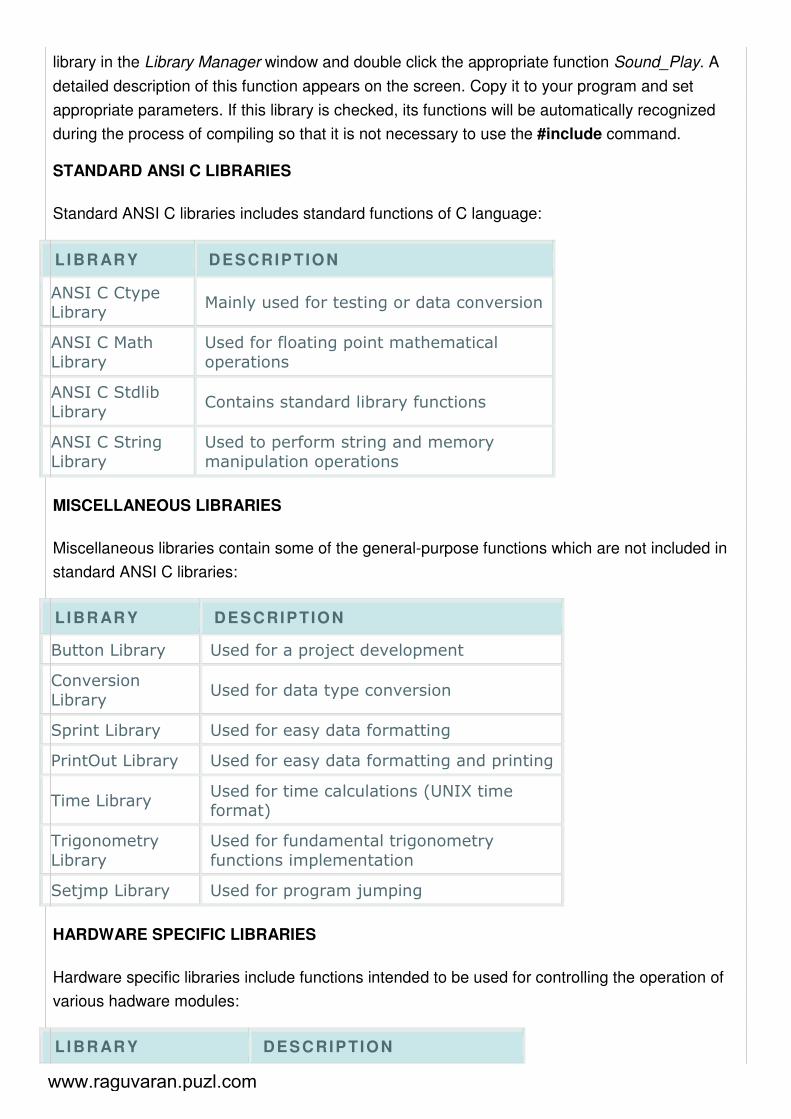
library in the Library Manager window and double click the appropriate function Sound_Play. A
detailed description of this function appears on the screen. Copy it to your program and set
appropriate parameters. If this library is checked, its functions will be automatically recognized
during the process of compiling so that it is not necessary to use the #include command.
STANDARD ANSI C LIBRARIES
Standard ANSI C libraries includes standard functions of C language:
LIBRARY DESCRIPTION
ANSI C Ctype Library
Mainly used for testing or data conversion
ANSI C Math
Library
Used for floating point mathematical
operations
ANSI C Stdlib
Library Contains standard library functions
ANSI C String
Library
Used to perform string and memory
manipulation operations
MISCELLANEOUS LIBRARIES
Miscellaneous libraries contain some of the general-purpose functions which are not included in
standard ANSI C libraries:
LIBRARY DESCRIPTION
Button Library Used for a project development
Conversion
Library Used for data type conversion
Sprint Library Used for easy data formatting
PrintOut Library Used for easy data formatting and printing
Time Library Used for time calculations (UNIX time format)
Trigonometry
Library
Used for fundamental trigonometry
functions implementation
Setjmp Library Used for program jumping
HARDWARE SPECIFIC LIBRARIES
Hardware specific libraries include functions intended to be used for controlling the operation of
various hadware modules:
LIBRARY DESCRIPTION
www.raguvaran.puzl.com
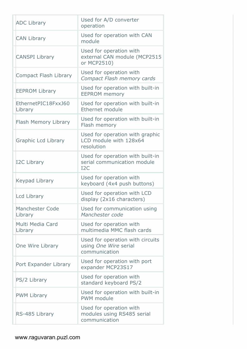
ADC Library Used for A/D converter operation
CAN Library Used for operation with CAN
module
CANSPI Library
Used for operation with
external CAN module (MCP2515 or MCP2510)
Compact Flash Library Used for operation with
Compact Flash memory cards
EEPROM Library Used for operation with built-in
EEPROM memory
EthernetPIC18FxxJ60
Library
Used for operation with built-in
Ethernet module
Flash Memory Library Used for operation with built-in Flash memory
Graphic Lcd Library Used for operation with graphic LCD module with 128x64
resolution
I2C Library
Used for operation with built-in
serial communication module I2C
Keypad Library Used for operation with
keyboard (4x4 push buttons)
Lcd Library Used for operation with LCD
display (2x16 characters)
Manchester Code
Library
Used for communication using
Manchester code
Multi Media Card Library
Used for operation with multimedia MMC flash cards
One Wire Library Used for operation with circuits using One Wire serial
communication
Port Expander Library Used for operation with port
expander MCP23S17
PS/2 Library Used for operation with standard keyboard PS/2
PWM Library Used for operation with built-in PWM module
RS-485 Library Used for operation with modules using RS485 serial
communication
www.raguvaran.puzl.com
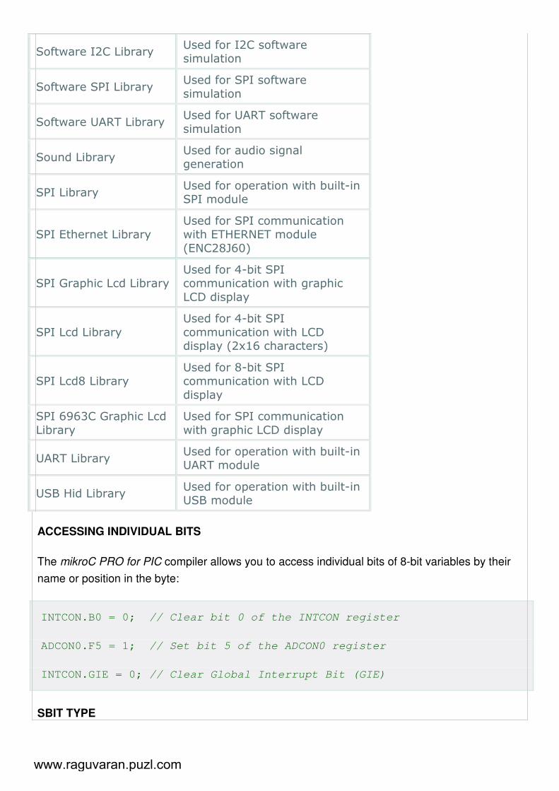
Software I2C Library Used for I2C software simulation
Software SPI Library Used for SPI software
simulation
Software UART Library Used for UART software
simulation
Sound Library Used for audio signal generation
SPI Library Used for operation with built-in SPI module
SPI Ethernet Library Used for SPI communication with ETHERNET module
(ENC28J60)
SPI Graphic Lcd Library Used for 4-bit SPI communication with graphic
LCD display
SPI Lcd Library
Used for 4-bit SPI
communication with LCD display (2x16 characters)
SPI Lcd8 Library Used for 8-bit SPI communication with LCD
display
SPI 6963C Graphic Lcd
Library
Used for SPI communication
with graphic LCD display
UART Library Used for operation with built-in UART module
USB Hid Library Used for operation with built-in USB module
ACCESSING INDIVIDUAL BITS
The mikroC PRO for PIC compiler allows you to access individual bits of 8-bit variables by their
name or position in the byte:
INTCON.B0 = 0; // Clear bit 0 of the INTCON register
ADCON0.F5 = 1; // Set bit 5 of the ADCON0 register
INTCON.GIE = 0; // Clear Global Interrupt Bit (GIE)
SBIT TYPE
www.raguvaran.puzl.com
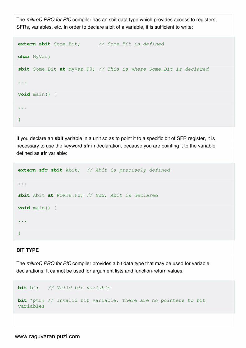
The mikroC PRO for PIC compiler has an sbit data type which provides access to registers,
SFRs, variables, etc. In order to declare a bit of a variable, it is sufficient to write:
extern sbit Some_Bit; // Some_Bit is defined
char MyVar;
sbit Some_Bit at MyVar.F0; // This is where Some_Bit is declared
...
void main()
...
If you declare an sbit variable in a unit so as to point it to a specific bit of SFR register, it is
necessary to use the keyword sfr in declaration, because you are pointing it to the variable
defined as sfr variable:
extern sfr sbit Abit; // Abit is precisely defined
...
sbit Abit at PORTB.F0; // Now, Abit is declared
void main()
...
BIT TYPE
The mikroC PRO for PIC compiler provides a bit data type that may be used for variable
declarations. It cannot be used for argument lists and function-return values.
bit bf; // Valid bit variable
bit *ptr; // Invalid bit variable. There are no pointers to bit
variables
www.raguvaran.puzl.com
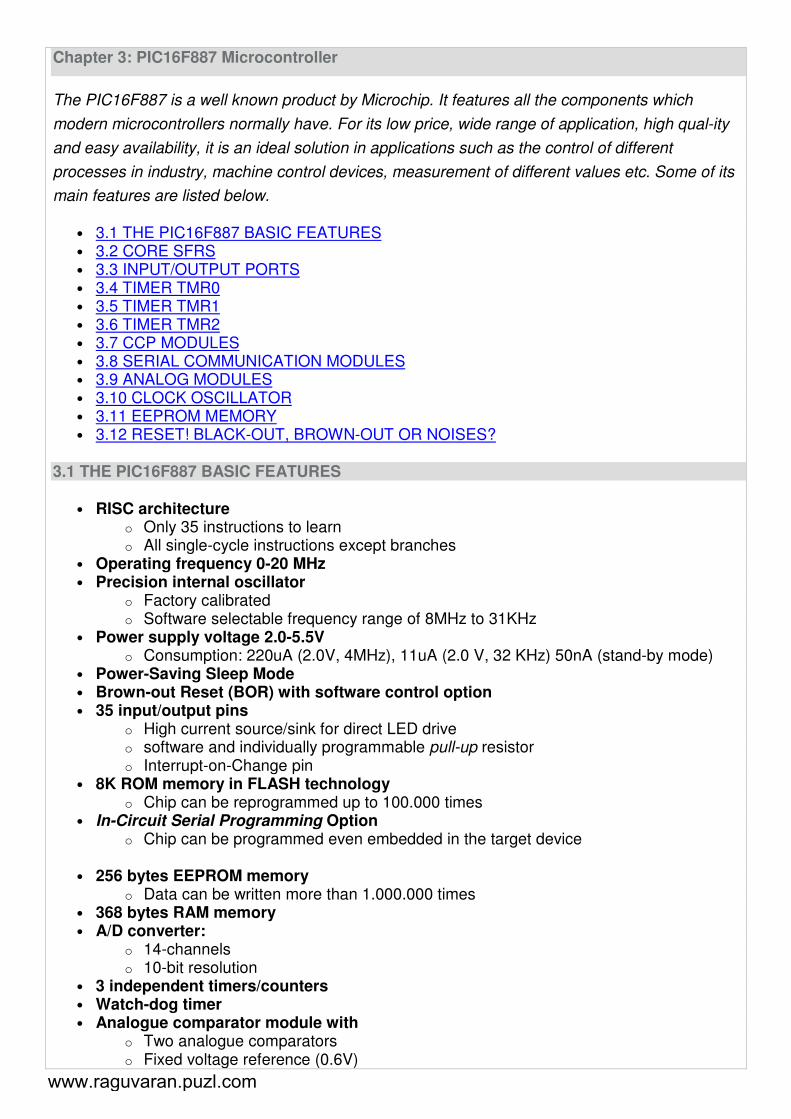
Chapter 3: PIC16F887 Microcontroller
The PIC16F887 is a well known product by Microchip. It features all the components which
modern microcontrollers normally have. For its low price, wide range of application, high qual-ity
and easy availability, it is an ideal solution in applications such as the control of different
processes in industry, machine control devices, measurement of different values etc. Some of its
main features are listed below.
• 3.1 THE PIC16F887 BASIC FEATURES • 3.2 CORE SFRS • 3.3 INPUT/OUTPUT PORTS • 3.4 TIMER TMR0 • 3.5 TIMER TMR1 • 3.6 TIMER TMR2 • 3.7 CCP MODULES • 3.8 SERIAL COMMUNICATION MODULES • 3.9 ANALOG MODULES • 3.10 CLOCK OSCILLATOR • 3.11 EEPROM MEMORY • 3.12 RESET! BLACK-OUT, BROWN-OUT OR NOISES?
3.1 THE PIC16F887 BASIC FEATURES
• RISC architecture o Only 35 instructions to learn o All single-cycle instructions except branches
• Operating frequency 0-20 MHz • Precision internal oscillator
o Factory calibrated o Software selectable frequency range of 8MHz to 31KHz
• Power supply voltage 2.0-5.5V o Consumption: 220uA (2.0V, 4MHz), 11uA (2.0 V, 32 KHz) 50nA (stand-by mode)
• Power-Saving Sleep Mode • Brown-out Reset (BOR) with software control option • 35 input/output pins
o High current source/sink for direct LED drive o software and individually programmable pull-up resistor o Interrupt-on-Change pin
• 8K ROM memory in FLASH technology o Chip can be reprogrammed up to 100.000 times
• In-Circuit Serial Programming Option o Chip can be programmed even embedded in the target device
• 256 bytes EEPROM memory o Data can be written more than 1.000.000 times
• 368 bytes RAM memory • A/D converter:
o 14-channels o 10-bit resolution
• 3 independent timers/counters • Watch-dog timer • Analogue comparator module with
o Two analogue comparators o Fixed voltage reference (0.6V)
www.raguvaran.puzl.com
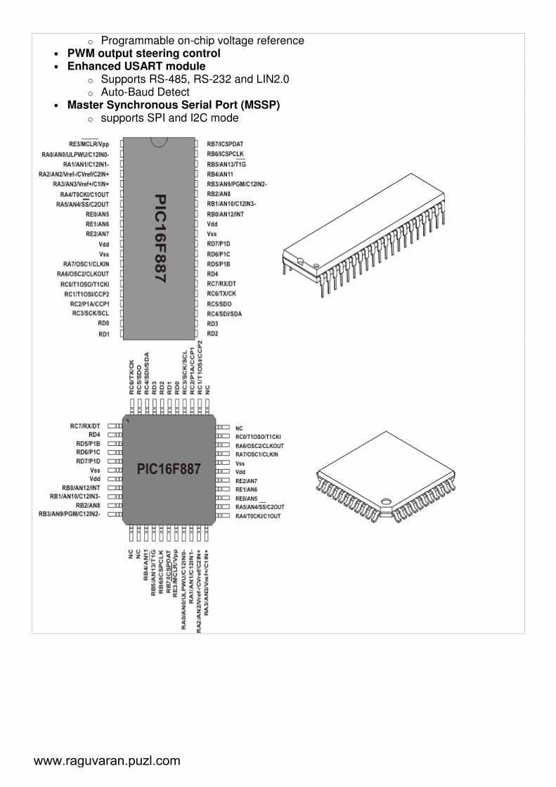
o Programmable on-chip voltage reference • PWM output steering control • Enhanced USART module
o Supports RS-485, RS-232 and LIN2.0 o Auto-Baud Detect
• Master Synchronous Serial Port (MSSP) o supports SPI and I2C mode
www.raguvaran.puzl.com
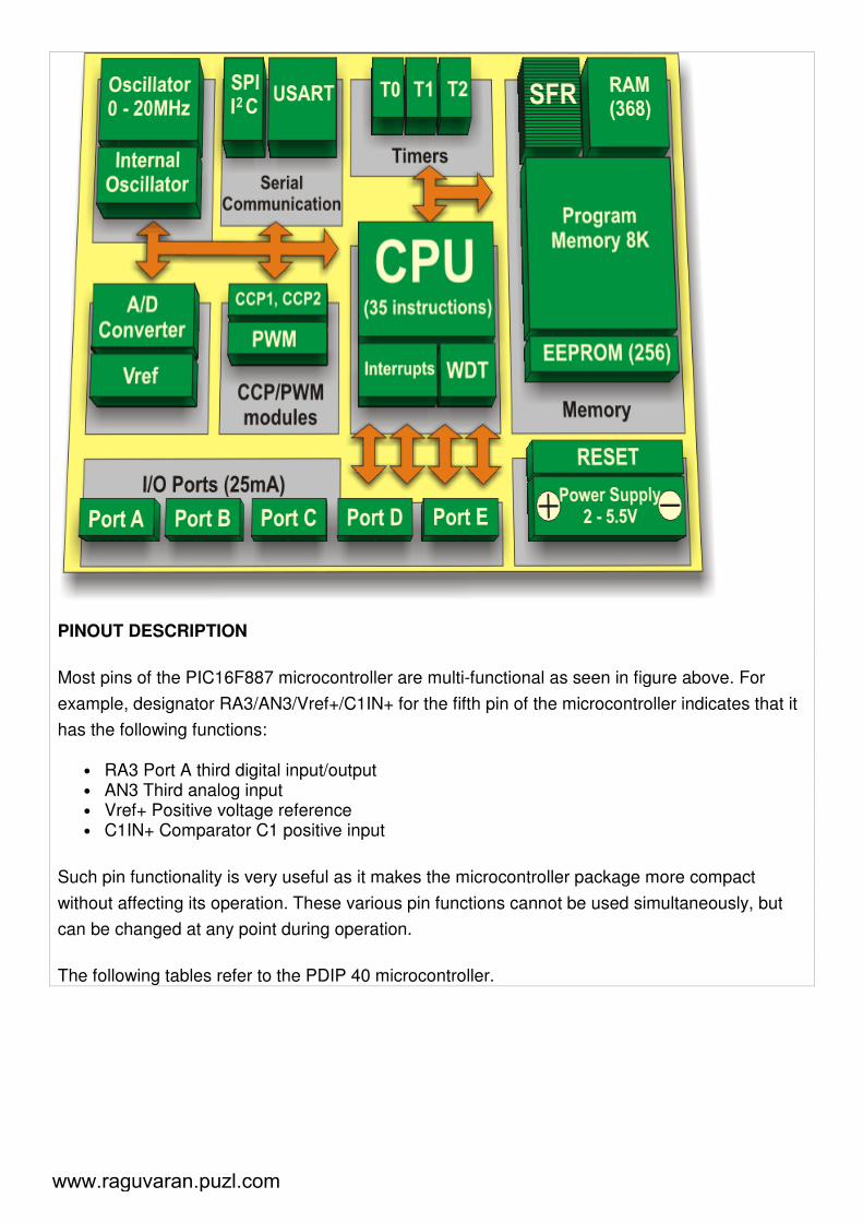
PINOUT DESCRIPTION
Most pins of the PIC16F887 microcontroller are multi-functional as seen in figure above. For
example, designator RA3/AN3/Vref+/C1IN+ for the fifth pin of the microcontroller indicates that it
has the following functions:
• RA3 Port A third digital input/output • AN3 Third analog input • Vref+ Positive voltage reference • C1IN+ Comparator C1 positive input
Such pin functionality is very useful as it makes the microcontroller package more compact
without affecting its operation. These various pin functions cannot be used simultaneously, but
can be changed at any point during operation.
The following tables refer to the PDIP 40 microcontroller.
www.raguvaran.puzl.com
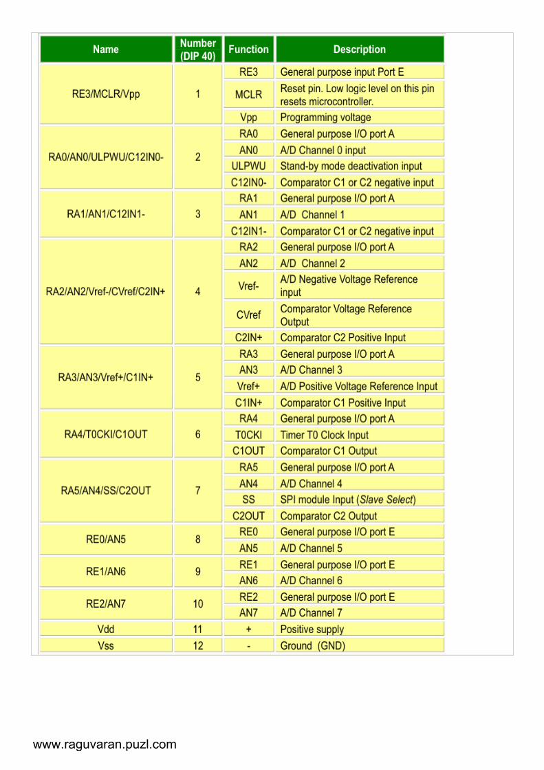
www.raguvaran.puzl.com
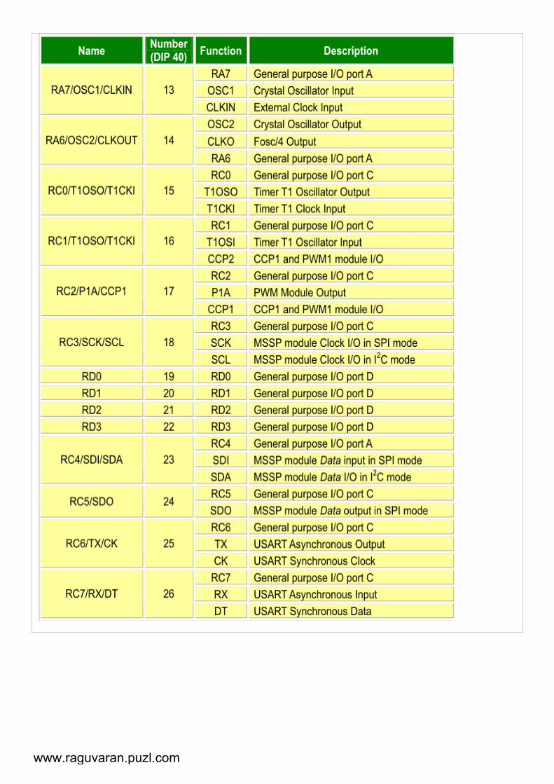
www.raguvaran.puzl.com
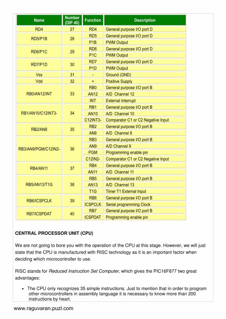
CENTRAL PROCESSOR UNIT (CPU)
We are not going to bore you with the operation of the CPU at this stage. However, we will just
state that the CPU is manufactured with RISC technology as it is an important factor when
deciding which microcontroller to use.
RISC stands for Reduced Instruction Set Computer, which gives the PIC16F877 two great
advantages:
• The CPU only recognizes 35 simple instructions. Just to mention that in order to program other microcontrollers in assembly language it is necessary to know more than 200 instructions by heart.
www.raguvaran.puzl.com
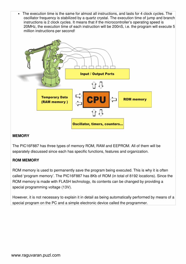
• The execution time is the same for almost all instructions, and lasts for 4 clock cycles. The oscillator frequency is stabilized by a quartz crystal. The execution time of jump and branch instructions is 2 clock cycles. It means that if the microcontroller’s operating speed is 20MHz, the execution time of each instruction will be 200nS, i.e. the program will execute 5 million instructions per second!
MEMORY
The PIC16F887 has three types of memory ROM, RAM and EEPROM. All of them will be
separately discussed since each has specific functions, features and organization.
ROM MEMORY
ROM memory is used to permanently save the program being executed. This is why it is often
called ‘program memory’. The PIC16F887 has 8Kb of ROM (in total of 8192 locations). Since the
ROM memory is made with FLASH technology, its contents can be changed by providing a
special programming voltage (13V).
However, it is not necessary to explain it in detail as being automatically performed by means of a
special program on the PC and a simple electronic device called the programmer.
www.raguvaran.puzl.com
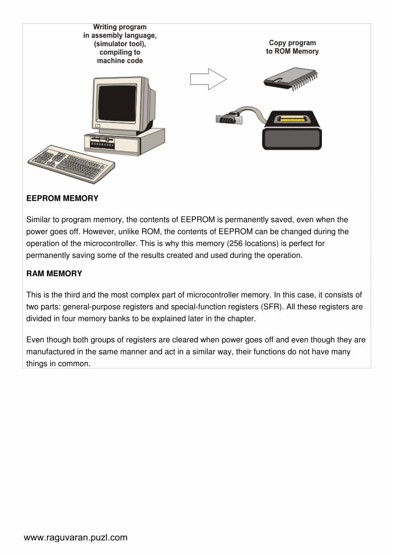
EEPROM MEMORY
Similar to program memory, the contents of EEPROM is permanently saved, even when the
power goes off. However, unlike ROM, the contents of EEPROM can be changed during the
operation of the microcontroller. This is why this memory (256 locations) is perfect for
permanently saving some of the results created and used during the operation.
RAM MEMORY
This is the third and the most complex part of microcontroller memory. In this case, it consists of
two parts: general-purpose registers and special-function registers (SFR). All these registers are
divided in four memory banks to be explained later in the chapter.
Even though both groups of registers are cleared when power goes off and even though they are
manufactured in the same manner and act in a similar way, their functions do not have many
things in common.
www.raguvaran.puzl.com
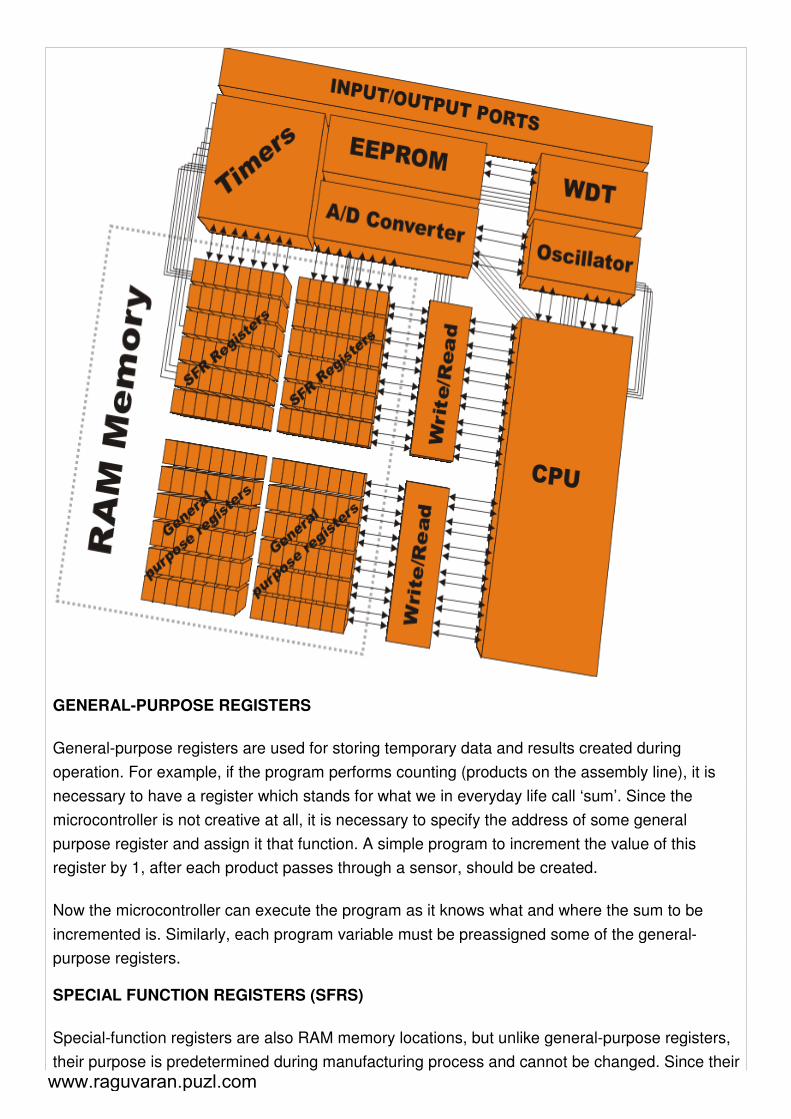
GENERAL-PURPOSE REGISTERS
General-purpose registers are used for storing temporary data and results created during
operation. For example, if the program performs counting (products on the assembly line), it is
necessary to have a register which stands for what we in everyday life call ‘sum’. Since the
microcontroller is not creative at all, it is necessary to specify the address of some general
purpose register and assign it that function. A simple program to increment the value of this
register by 1, after each product passes through a sensor, should be created.
Now the microcontroller can execute the program as it knows what and where the sum to be
incremented is. Similarly, each program variable must be preassigned some of the general-
purpose registers.
SPECIAL FUNCTION REGISTERS (SFRS)
Special-function registers are also RAM memory locations, but unlike general-purpose registers,
their purpose is predetermined during manufacturing process and cannot be changed. Since their
www.raguvaran.puzl.com

bits are connected to particular circuits on the chip (A/D converter, serial communication module,
etc.), any change of their contents directly affects the operation of the microcontroller or some of
its circuits. For example, the ADCON0 register controls the operation of A/D converter. By
changing its bits it is determined which port pin is to be configured as converter input, the moment
conversion is to start as well as the speed of conversion.
Another feature of these memory locations is that they have their names (both registers and their
bits), which considerably simplifies the process of writing a program. Since high-level
programming languages can use the list of all registers with their exact addresses, it is enough to
specify the name of a register in order to read or change its contents.
RAM MEMORY BANKS
The RAM memory is partitioned into four banks. Prior to accessing any register during program
writing (in order to read or change its contents), it is necessary to select the bank which contains
that register. Two bits of the STATUS register are used for bank selection to be discussed later. In
order to simplify the operation, the most commonly used SFRs have the same address in all
banks, which enables them to be easily accessed.
www.raguvaran.puzl.com
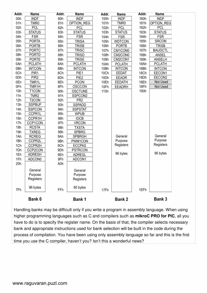
Handling banks may be difficult only if you write a program in assembly language. When using
higher programming languages such as C and compilers such as mikroC PRO for PIC, all you
have to do is to specify the register name. On the basis of that, the compiler selects necessary
bank and appropriate instructions used for bank selection will be built in the code during the
process of compilation. You have been using only assembly language so far and this is the first
time you use the C compiler, haven’t you? Isn’t this a wonderful news?
www.raguvaran.puzl.com
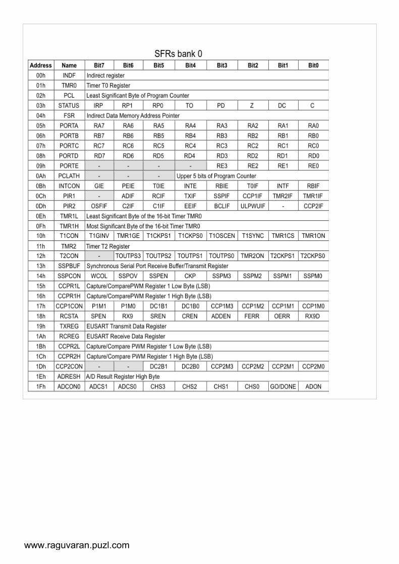
www.raguvaran.puzl.com
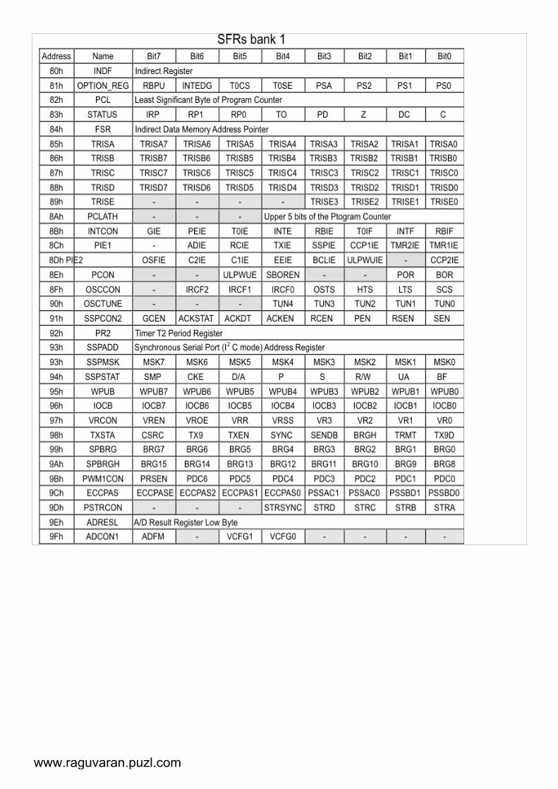
www.raguvaran.puzl.com
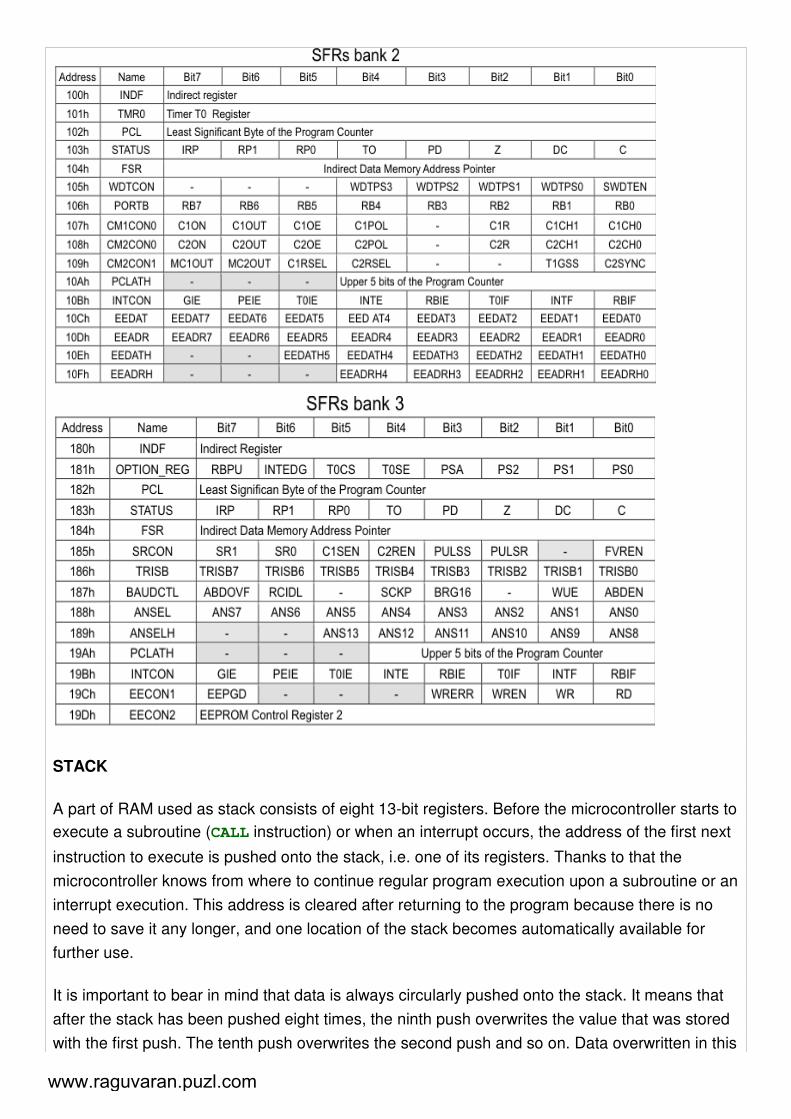
STACK
A part of RAM used as stack consists of eight 13-bit registers. Before the microcontroller starts to
execute a subroutine (CALL instruction) or when an interrupt occurs, the address of the first next
instruction to execute is pushed onto the stack, i.e. one of its registers. Thanks to that the
microcontroller knows from where to continue regular program execution upon a subroutine or an
interrupt execution. This address is cleared after returning to the program because there is no
need to save it any longer, and one location of the stack becomes automatically available for
further use.
It is important to bear in mind that data is always circularly pushed onto the stack. It means that
after the stack has been pushed eight times, the ninth push overwrites the value that was stored
with the first push. The tenth push overwrites the second push and so on. Data overwritten in this
www.raguvaran.puzl.com
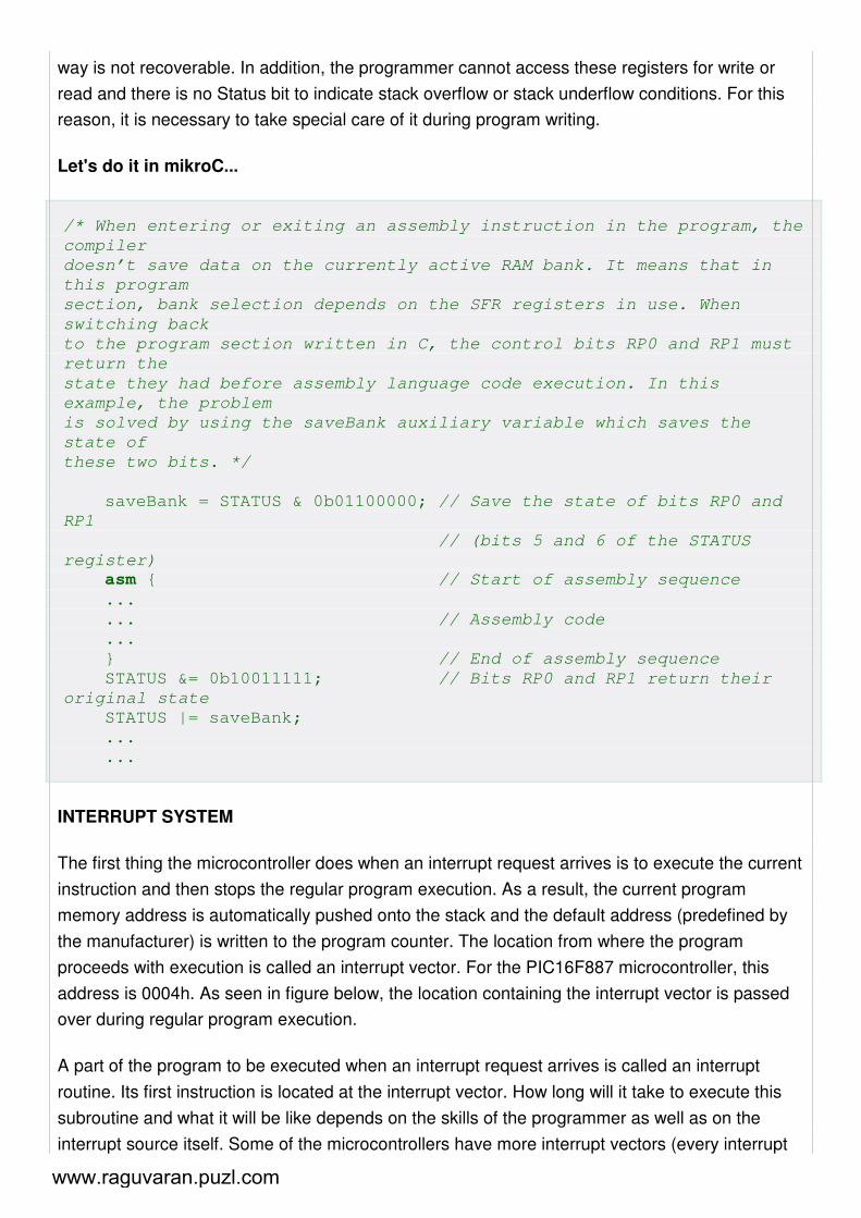
way is not recoverable. In addition, the programmer cannot access these registers for write or
read and there is no Status bit to indicate stack overflow or stack underflow conditions. For this
reason, it is necessary to take special care of it during program writing.
Let's do it in mikroC...
/* When entering or exiting an assembly instruction in the program, the
compiler
doesn’t save data on the currently active RAM bank. It means that in
this program
section, bank selection depends on the SFR registers in use. When
switching back
to the program section written in C, the control bits RP0 and RP1 must
return the
state they had before assembly language code execution. In this
example, the problem
is solved by using the saveBank auxiliary variable which saves the
state of
these two bits. */
saveBank = STATUS & 0b01100000; // Save the state of bits RP0 and
RP1
// (bits 5 and 6 of the STATUS
register)
asm // Start of assembly sequence
...
... // Assembly code
...
// End of assembly sequence
STATUS &= 0b10011111; // Bits RP0 and RP1 return their
original state
STATUS |= saveBank;
...
...
INTERRUPT SYSTEM
The first thing the microcontroller does when an interrupt request arrives is to execute the current
instruction and then stops the regular program execution. As a result, the current program
memory address is automatically pushed onto the stack and the default address (predefined by
the manufacturer) is written to the program counter. The location from where the program
proceeds with execution is called an interrupt vector. For the PIC16F887 microcontroller, this
address is 0004h. As seen in figure below, the location containing the interrupt vector is passed
over during regular program execution.
A part of the program to be executed when an interrupt request arrives is called an interrupt
routine. Its first instruction is located at the interrupt vector. How long will it take to execute this
subroutine and what it will be like depends on the skills of the programmer as well as on the
interrupt source itself. Some of the microcontrollers have more interrupt vectors (every interrupt
www.raguvaran.puzl.com
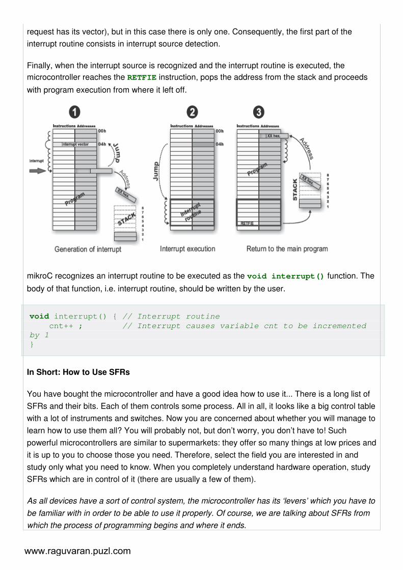
request has its vector), but in this case there is only one. Consequently, the first part of the
interrupt routine consists in interrupt source detection.
Finally, when the interrupt source is recognized and the interrupt routine is executed, the
microcontroller reaches the RETFIE instruction, pops the address from the stack and proceeds
with program execution from where it left off.
mikroC recognizes an interrupt routine to be executed as the void interrupt() function. The
body of that function, i.e. interrupt routine, should be written by the user.
void interrupt() // Interrupt routine
cnt++ ; // Interrupt causes variable cnt to be incremented
by 1
In Short: How to Use SFRs
You have bought the microcontroller and have a good idea how to use it... There is a long list of
SFRs and their bits. Each of them controls some process. All in all, it looks like a big control table
with a lot of instruments and switches. Now you are concerned about whether you will manage to
learn how to use them all? You will probably not, but don’t worry, you don’t have to! Such
powerful microcontrollers are similar to supermarkets: they offer so many things at low prices and
it is up to you to choose those you need. Therefore, select the field you are interested in and
study only what you need to know. When you completely understand hardware operation, study
SFRs which are in control of it (there are usually a few of them).
As all devices have a sort of control system, the microcontroller has its ‘levers’ which you have to
be familiar with in order to be able to use it properly. Of course, we are talking about SFRs from
which the process of programming begins and where it ends.
www.raguvaran.puzl.com
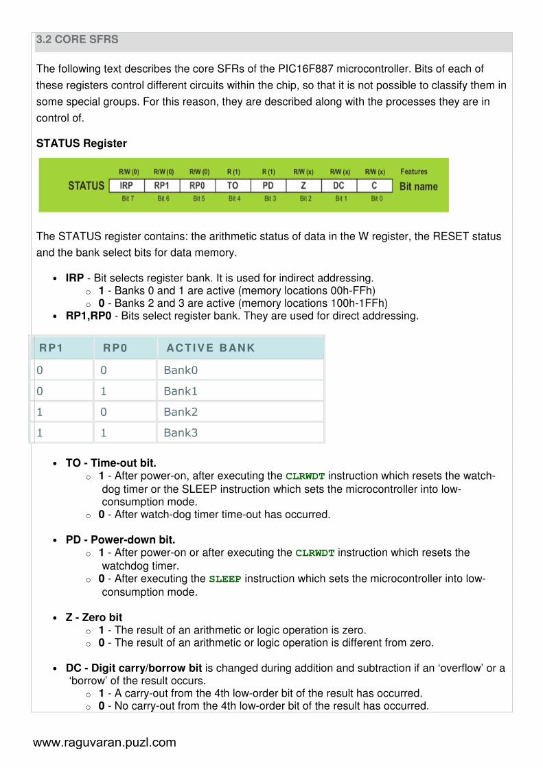
3.2 CORE SFRS
The following text describes the core SFRs of the PIC16F887 microcontroller. Bits of each of
these registers control different circuits within the chip, so that it is not possible to classify them in
some special groups. For this reason, they are described along with the processes they are in
control of.
STATUS Register
The STATUS register contains: the arithmetic status of data in the W register, the RESET status
and the bank select bits for data memory.
• IRP - Bit selects register bank. It is used for indirect addressing. o 1 - Banks 0 and 1 are active (memory locations 00h-FFh) o 0 - Banks 2 and 3 are active (memory locations 100h-1FFh)
• RP1,RP0 - Bits select register bank. They are used for direct addressing.
RP1 RP0 ACTIVE BANK
0 0 Bank0
0 1 Bank1
1 0 Bank2
1 1 Bank3
• TO - Time-out bit. o 1 - After power-on, after executing the CLRWDT instruction which resets the watch-
dog timer or the SLEEP instruction which sets the microcontroller into low-consumption mode.
o 0 - After watch-dog timer time-out has occurred.
• PD - Power-down bit. o 1 - After power-on or after executing the CLRWDT instruction which resets the
watchdog timer. o 0 - After executing the SLEEP instruction which sets the microcontroller into low-
consumption mode.
• Z - Zero bit o 1 - The result of an arithmetic or logic operation is zero. o 0 - The result of an arithmetic or logic operation is different from zero.
• DC - Digit carry/borrow bit is changed during addition and subtraction if an ‘overflow’ or a ‘borrow’ of the result occurs.
o 1 - A carry-out from the 4th low-order bit of the result has occurred. o 0 - No carry-out from the 4th low-order bit of the result has occurred.
www.raguvaran.puzl.com
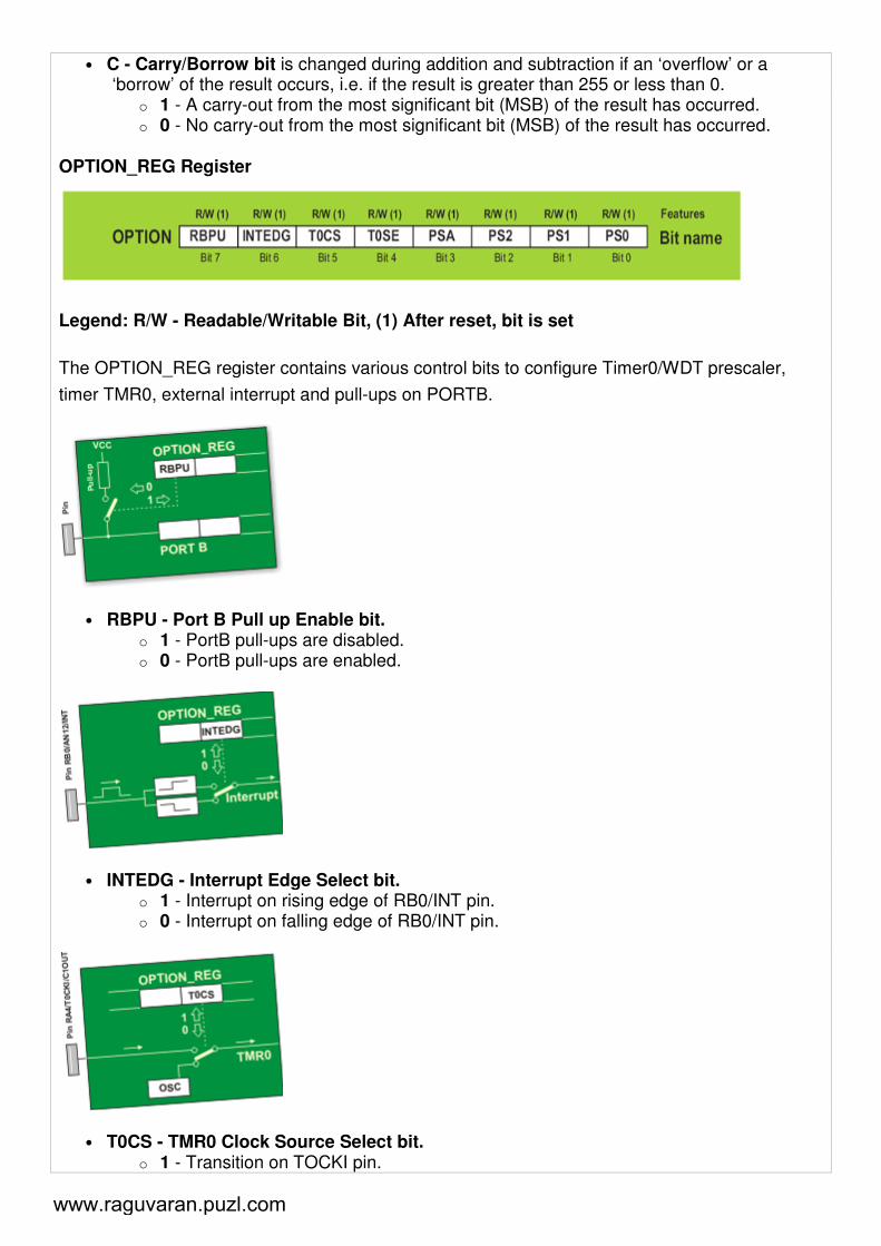
• C - Carry/Borrow bit is changed during addition and subtraction if an ‘overflow’ or a ‘borrow’ of the result occurs, i.e. if the result is greater than 255 or less than 0.
o 1 - A carry-out from the most significant bit (MSB) of the result has occurred. o 0 - No carry-out from the most significant bit (MSB) of the result has occurred.
OPTION_REG Register
Legend: R/W - Readable/Writable Bit, (1) After reset, bit is set
The OPTION_REG register contains various control bits to configure Timer0/WDT prescaler,
timer TMR0, external interrupt and pull-ups on PORTB.
• RBPU - Port B Pull up Enable bit. o 1 - PortB pull-ups are disabled. o 0 - PortB pull-ups are enabled.
• INTEDG - Interrupt Edge Select bit. o 1 - Interrupt on rising edge of RB0/INT pin. o 0 - Interrupt on falling edge of RB0/INT pin.
• T0CS - TMR0 Clock Source Select bit. o 1 - Transition on TOCKI pin.
www.raguvaran.puzl.com
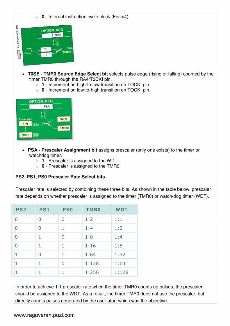
o 0 - Internal instruction cycle clock (Fosc/4).
• T0SE - TMR0 Source Edge Select bit selects pulse edge (rising or falling) counted by the timer TMR0 through the RA4/T0CKI pin.
o 1 - Increment on high-to-low transition on TOCKI pin. o 0 - Increment on low-to-high transition on TOCKI pin.
• PSA - Prescaler Assignment bit assigns prescaler (only one exists) to the timer or watchdog timer.
o 1 - Prescaler is assigned to the WDT. o 0 - Prescaler is assigned to the TMR0.
PS2, PS1, PS0 Prescaler Rate Select bits
Prescaler rate is selected by combining these three bits. As shown in the table below, prescaler
rate depends on whether prescaler is assigned to the timer (TMR0) or watch-dog timer (WDT).
PS2 PS1 PS0 TMR0 WDT
0 0 0 1:2 1:1
0 0 1 1:4 1:2
0 1 0 1:8 1:4
0 1 1 1:16 1:8
1 0 1 1:64 1:32
1 1 0 1:128 1:64
1 1 1 1:256 1:128
In order to achieve 1:1 prescaler rate when the timer TMR0 counts up pulses, the prescaler
should be assigned to the WDT. As a result, the timer TMR0 does not use the prescaler, but
directly counts pulses generated by the oscillator, which was the objective.
www.raguvaran.puzl.com
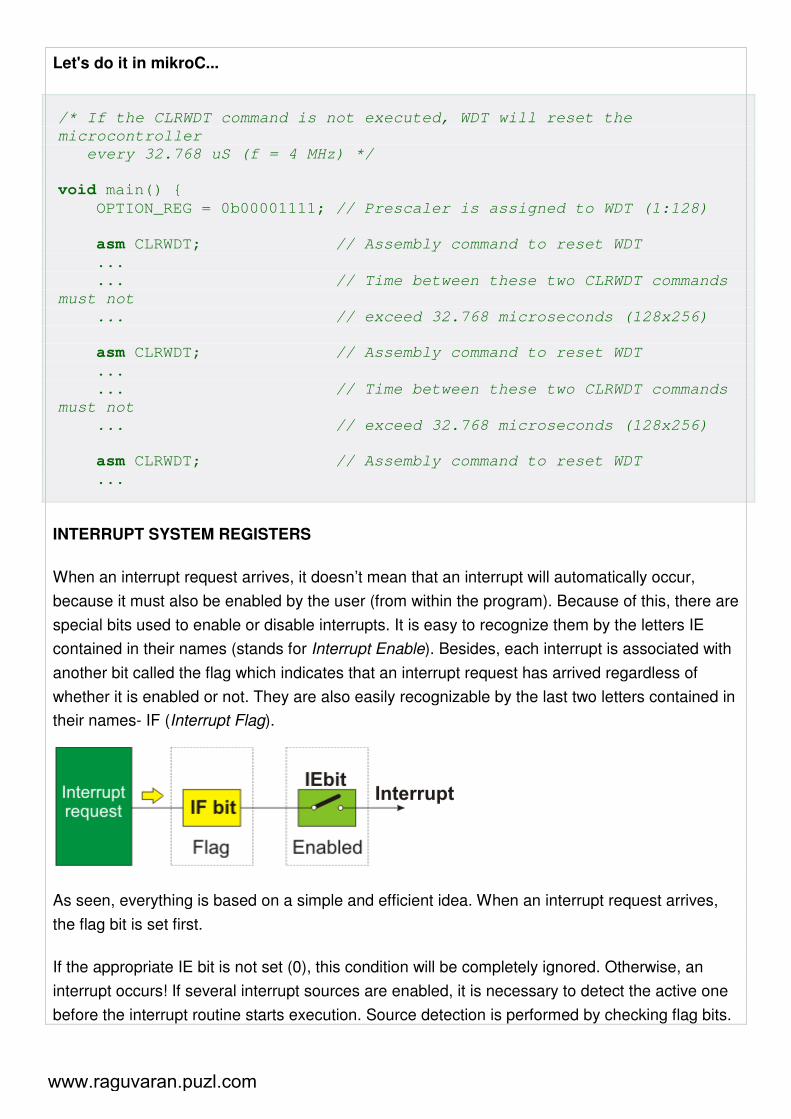
Let's do it in mikroC...
/* If the CLRWDT command is not executed, WDT will reset the
microcontroller
every 32.768 uS (f = 4 MHz) */
void main()
OPTION_REG = 0b00001111; // Prescaler is assigned to WDT (1:128)
asm CLRWDT; // Assembly command to reset WDT
...
... // Time between these two CLRWDT commands
must not
... // exceed 32.768 microseconds (128x256)
asm CLRWDT; // Assembly command to reset WDT
...
... // Time between these two CLRWDT commands
must not
... // exceed 32.768 microseconds (128x256)
asm CLRWDT; // Assembly command to reset WDT
...
INTERRUPT SYSTEM REGISTERS
When an interrupt request arrives, it doesn’t mean that an interrupt will automatically occur,
because it must also be enabled by the user (from within the program). Because of this, there are
special bits used to enable or disable interrupts. It is easy to recognize them by the letters IE
contained in their names (stands for Interrupt Enable). Besides, each interrupt is associated with
another bit called the flag which indicates that an interrupt request has arrived regardless of
whether it is enabled or not. They are also easily recognizable by the last two letters contained in
their names- IF (Interrupt Flag).
As seen, everything is based on a simple and efficient idea. When an interrupt request arrives,
the flag bit is set first.
If the appropriate IE bit is not set (0), this condition will be completely ignored. Otherwise, an
interrupt occurs! If several interrupt sources are enabled, it is necessary to detect the active one
before the interrupt routine starts execution. Source detection is performed by checking flag bits.
www.raguvaran.puzl.com
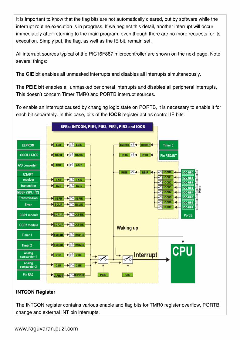
It is important to know that the flag bits are not automatically cleared, but by software while the
interrupt routine execution is in progress. If we neglect this detail, another interrupt will occur
immediately after returning to the main program, even though there are no more requests for its
execution. Simply put, the flag, as well as the IE bit, remain set.
All interrupt sources typical of the PIC16F887 microcontroller are shown on the next page. Note
several things:
The GIE bit enables all unmasked interrupts and disables all interrupts simultaneously.
The PEIE bit enables all unmasked peripheral interrupts and disables all peripheral interrupts.
This doesn’t concern Timer TMR0 and PORTB interrupt sources.
To enable an interrupt caused by changing logic state on PORTB, it is necessary to enable it for
each bit separately. In this case, bits of the IOCB register act as control IE bits.
INTCON Register
The INTCON register contains various enable and flag bits for TMR0 register overflow, PORTB
change and external INT pin interrupts.
www.raguvaran.puzl.com
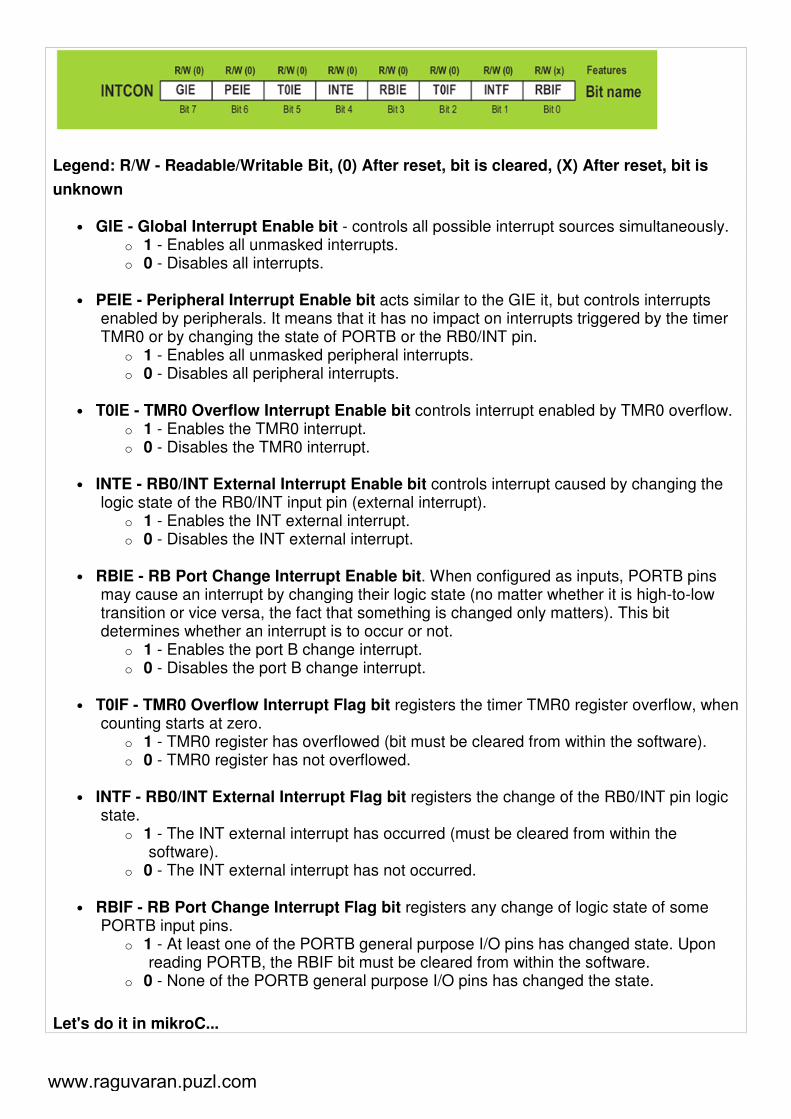
Legend: R/W - Readable/Writable Bit, (0) After reset, bit is cleared, (X) After reset, bit is
unknown
• GIE - Global Interrupt Enable bit - controls all possible interrupt sources simultaneously. o 1 - Enables all unmasked interrupts. o 0 - Disables all interrupts.
• PEIE - Peripheral Interrupt Enable bit acts similar to the GIE it, but controls interrupts enabled by peripherals. It means that it has no impact on interrupts triggered by the timer TMR0 or by changing the state of PORTB or the RB0/INT pin.
o 1 - Enables all unmasked peripheral interrupts. o 0 - Disables all peripheral interrupts.
• T0IE - TMR0 Overflow Interrupt Enable bit controls interrupt enabled by TMR0 overflow. o 1 - Enables the TMR0 interrupt. o 0 - Disables the TMR0 interrupt.
• INTE - RB0/INT External Interrupt Enable bit controls interrupt caused by changing the logic state of the RB0/INT input pin (external interrupt).
o 1 - Enables the INT external interrupt. o 0 - Disables the INT external interrupt.
• RBIE - RB Port Change Interrupt Enable bit. When configured as inputs, PORTB pins may cause an interrupt by changing their logic state (no matter whether it is high-to-low transition or vice versa, the fact that something is changed only matters). This bit determines whether an interrupt is to occur or not.
o 1 - Enables the port B change interrupt. o 0 - Disables the port B change interrupt.
• T0IF - TMR0 Overflow Interrupt Flag bit registers the timer TMR0 register overflow, when counting starts at zero.
o 1 - TMR0 register has overflowed (bit must be cleared from within the software). o 0 - TMR0 register has not overflowed.
• INTF - RB0/INT External Interrupt Flag bit registers the change of the RB0/INT pin logic state.
o 1 - The INT external interrupt has occurred (must be cleared from within the software).
o 0 - The INT external interrupt has not occurred.
• RBIF - RB Port Change Interrupt Flag bit registers any change of logic state of some PORTB input pins.
o 1 - At least one of the PORTB general purpose I/O pins has changed state. Upon reading PORTB, the RBIF bit must be cleared from within the software.
o 0 - None of the PORTB general purpose I/O pins has changed the state.
Let's do it in mikroC...
www.raguvaran.puzl.com
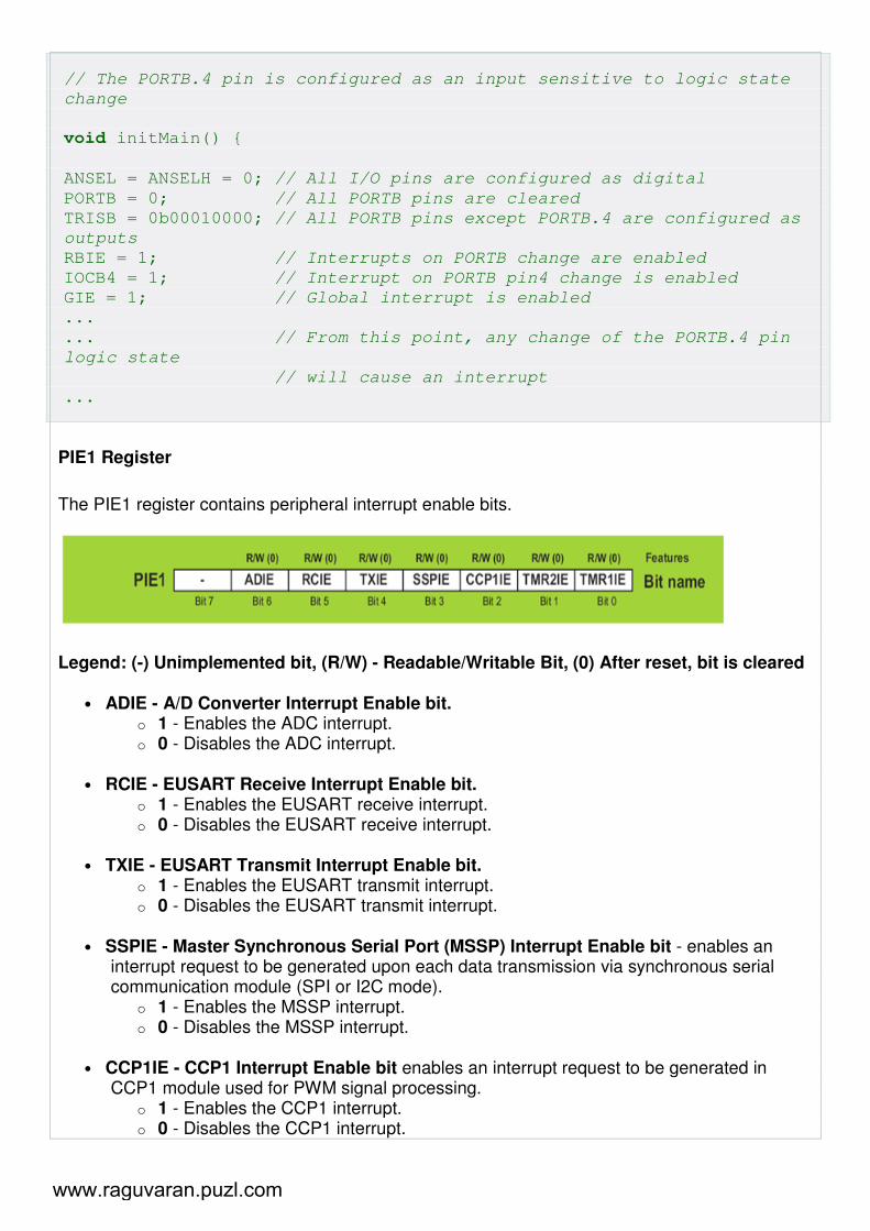
// The PORTB.4 pin is configured as an input sensitive to logic state
change
void initMain()
ANSEL = ANSELH = 0; // All I/O pins are configured as digital
PORTB = 0; // All PORTB pins are cleared
TRISB = 0b00010000; // All PORTB pins except PORTB.4 are configured as
outputs
RBIE = 1; // Interrupts on PORTB change are enabled
IOCB4 = 1; // Interrupt on PORTB pin4 change is enabled
GIE = 1; // Global interrupt is enabled
...
... // From this point, any change of the PORTB.4 pin
logic state
// will cause an interrupt
...
PIE1 Register
The PIE1 register contains peripheral interrupt enable bits.
Legend: (-) Unimplemented bit, (R/W) - Readable/Writable Bit, (0) After reset, bit is cleared
• ADIE - A/D Converter Interrupt Enable bit. o 1 - Enables the ADC interrupt. o 0 - Disables the ADC interrupt.
• RCIE - EUSART Receive Interrupt Enable bit. o 1 - Enables the EUSART receive interrupt. o 0 - Disables the EUSART receive interrupt.
• TXIE - EUSART Transmit Interrupt Enable bit. o 1 - Enables the EUSART transmit interrupt. o 0 - Disables the EUSART transmit interrupt.
• SSPIE - Master Synchronous Serial Port (MSSP) Interrupt Enable bit - enables an interrupt request to be generated upon each data transmission via synchronous serial communication module (SPI or I2C mode).
o 1 - Enables the MSSP interrupt. o 0 - Disables the MSSP interrupt.
• CCP1IE - CCP1 Interrupt Enable bit enables an interrupt request to be generated in CCP1 module used for PWM signal processing.
o 1 - Enables the CCP1 interrupt. o 0 - Disables the CCP1 interrupt.
www.raguvaran.puzl.com
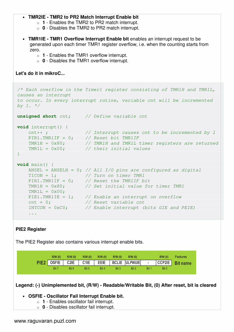
• TMR2IE - TMR2 to PR2 Match Interrupt Enable bit o 1 - Enables the TMR2 to PR2 match interrupt. o 0 - Disables the TMR2 to PR2 match interrupt.
• TMR1IE - TMR1 Overflow Interrupt Enable bit enables an interrupt request to be generated upon each timer TMR1 register overflow, i.e. when the counting starts from zero.
o 1 - Enables the TMR1 overflow interrupt. o 0 - Disables the TMR1 overflow interrupt.
Let's do it in mikroC...
/* Each overflow in the Timer1 register consisting of TMR1H and TMR1L,
causes an interrupt
to occur. In every interrupt rutine, variable cnt will be incremented
by 1. */
unsigned short cnt; // Define variable cnt
void interrupt()
cnt++ ; // Interrupt causes cnt to be incremented by 1
PIR1.TMR1IF = 0; // Reset bit TMR1IF
TMR1H = 0x80; // TMR1H and TMR1L timer registers are returned
TMR1L = 0x00; // their initial values
void main()
ANSEL = ANSELH = 0; // All I/O pins are configured as digital
T1CON = 1; // Turn on timer TMR1
PIR1.TMR1IF = 0; // Reset the TMR1IF bit
TMR1H = 0x80; // Set initial value for timer TMR1
TMR1L = 0x00;
PIE1.TMR1IE = 1; // Enable an interrupt on overflow
cnt = 0; // Reset variable cnt
INTCON = 0xC0; // Enable interrupt (bits GIE and PEIE)
...
PIE2 Register
The PIE2 Register also contains various interrupt enable bits.
Legend: (-) Unimplemented bit, (R/W) - Readable/Writable Bit, (0) After reset, bit is cleared
• OSFIE - Oscillator Fail Interrupt Enable bit. o 1 - Enables oscillator fail interrupt. o 0 - Disables oscillator fail interrupt.
www.raguvaran.puzl.com
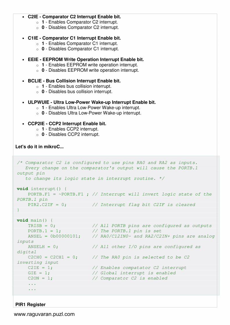
• C2IE - Comparator C2 Interrupt Enable bit. o 1 - Enables Comparator C2 interrupt. o 0 - Disables Comparator C2 interrupt.
• C1IE - Comparator C1 Interrupt Enable bit. o 1 - Enables Comparator C1 interrupt. o 0 - Disables Comparator C1 interrupt.
• EEIE - EEPROM Write Operation Interrupt Enable bit. o 1 - Enables EEPROM write operation interrupt. o 0 - Disables EEPROM write operation interrupt.
• BCLIE - Bus Collision Interrupt Enable bit. o 1 - Enables bus collision interrupt. o 0 - Disables bus collision interrupt.
• ULPWUIE - Ultra Low-Power Wake-up Interrupt Enable bit. o 1 - Enables Ultra Low-Power Wake-up interrupt. o 0 - Disables Ultra Low-Power Wake-up interrupt.
• CCP2IE - CCP2 Interrupt Enable bit. o 1 - Enables CCP2 interrupt. o 0 - Disables CCP2 interrupt.
Let's do it in mikroC...
/* Comparator C2 is configured to use pins RA0 and RA2 as inputs.
Every change on the comparator's output will cause the PORTB.1
output pin
to change its logic state in interrupt routine. */
void interrupt()
PORTB.F1 = ~PORTB.F1 ; // Interrupt will invert logic state of the
PORTB.1 pin
PIR2.C2IF = 0; // Interrupt flag bit C2IF is cleared
void main()
TRISB = 0; // All PORTB pins are configured as outputs
PORTB.1 = 1; // The PORTB.1 pin is set
ANSEL = 0b00000101; // RA0/C12IN0- and RA2/C2IN+ pins are analog
inputs
ANSELH = 0; // All other I/O pins are configured as
digital
C2CH0 = C2CH1 = 0; // The RA0 pin is selected to be C2
inverting input
C2IE = 1; // Enables compatator C2 interrupt
GIE = 1; // Global interrupt is enabled
C2ON = 1; // Comparator C2 is enabled
...
...
PIR1 Register
www.raguvaran.puzl.com
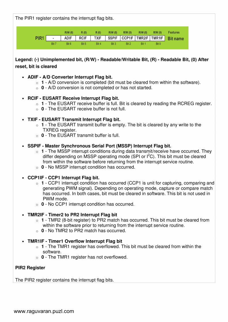
The PIR1 register contains the interrupt flag bits.
Legend: (-) Unimplemented bit, (R/W) - Readable/Writable Bit, (R) - Readable Bit, (0) After
reset, bit is cleared
• ADIF - A/D Converter Interrupt Flag bit. o 1 - A/D conversion is completed (bit must be cleared from within the software). o 0 - A/D conversion is not completed or has not started.
• RCIF - EUSART Receive Interrupt Flag bit. o 1 - The EUSART receive buffer is full. Bit is cleared by reading the RCREG register. o 0 - The EUSART receive buffer is not full.
• TXIF - EUSART Transmit Interrupt Flag bit. o 1 - The EUSART transmit buffer is empty. The bit is cleared by any write to the
TXREG register. o 0 - The EUSART transmit buffer is full.
• SSPIF - Master Synchronous Serial Port (MSSP) Interrupt Flag bit. o 1 - The MSSP interrupt conditions during data transmit/receive have occurred. They
differ depending on MSSP operating mode (SPI or I2C). This bit must be cleared from within the software before returning from the interrupt service routine.
o 0 - No MSSP interrupt condition has occurred.
• CCP1IF - CCP1 Interrupt Flag bit. o 1 - CCP1 interrupt condition has occurred (CCP1 is unit for capturing, comparing and
generating PWM signal). Depending on operating mode, capture or compare match has occurred. In both cases, bit must be cleared in software. This bit is not used in PWM mode.
o 0 - No CCP1 interrupt condition has occurred.
• TMR2IF - Timer2 to PR2 Interrupt Flag bit o 1 - TMR2 (8-bit register) to PR2 match has occurred. This bit must be cleared from
within the software prior to returning from the interrupt service routine. o 0 - No TMR2 to PR2 match has occurred.
• TMR1IF - Timer1 Overflow Interrupt Flag bit o 1 - The TMR1 register has overflowed. This bit must be cleared from within the
software. o 0 - The TMR1 register has not overflowed.
PIR2 Register
The PIR2 register contains the interrupt flag bits.
www.raguvaran.puzl.com
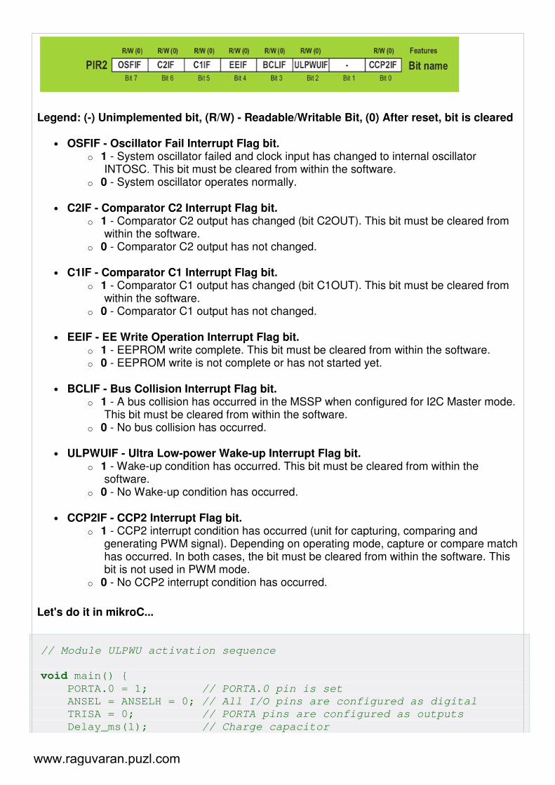
Legend: (-) Unimplemented bit, (R/W) - Readable/Writable Bit, (0) After reset, bit is cleared
• OSFIF - Oscillator Fail Interrupt Flag bit. o 1 - System oscillator failed and clock input has changed to internal oscillator
INTOSC. This bit must be cleared from within the software. o 0 - System oscillator operates normally.
• C2IF - Comparator C2 Interrupt Flag bit. o 1 - Comparator C2 output has changed (bit C2OUT). This bit must be cleared from
within the software. o 0 - Comparator C2 output has not changed.
• C1IF - Comparator C1 Interrupt Flag bit. o 1 - Comparator C1 output has changed (bit C1OUT). This bit must be cleared from
within the software. o 0 - Comparator C1 output has not changed.
• EEIF - EE Write Operation Interrupt Flag bit. o 1 - EEPROM write complete. This bit must be cleared from within the software. o 0 - EEPROM write is not complete or has not started yet.
• BCLIF - Bus Collision Interrupt Flag bit. o 1 - A bus collision has occurred in the MSSP when configured for I2C Master mode.
This bit must be cleared from within the software. o 0 - No bus collision has occurred.
• ULPWUIF - Ultra Low-power Wake-up Interrupt Flag bit. o 1 - Wake-up condition has occurred. This bit must be cleared from within the
software. o 0 - No Wake-up condition has occurred.
• CCP2IF - CCP2 Interrupt Flag bit. o 1 - CCP2 interrupt condition has occurred (unit for capturing, comparing and
generating PWM signal). Depending on operating mode, capture or compare match has occurred. In both cases, the bit must be cleared from within the software. This bit is not used in PWM mode.
o 0 - No CCP2 interrupt condition has occurred.
Let's do it in mikroC...
// Module ULPWU activation sequence
void main()
PORTA.0 = 1; // PORTA.0 pin is set
ANSEL = ANSELH = 0; // All I/O pins are configured as digital
TRISA = 0; // PORTA pins are configured as outputs
Delay_ms(1); // Charge capacitor
www.raguvaran.puzl.com
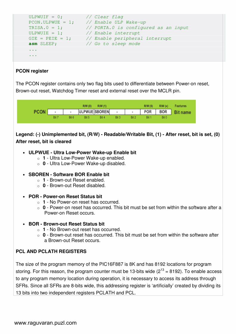
ULPWUIF = 0; // Clear flag
PCON.ULPWUE = 1; // Enable ULP Wake-up
TRISA.0 = 1; // PORTA.0 is configured as an input
ULPWUIE = 1; // Enable interrupt
GIE = PEIE = 1; // Enable peripheral interrupt
asm SLEEP; // Go to sleep mode
...
...
PCON register
The PCON register contains only two flag bits used to differentiate between Power-on reset,
Brown-out reset, Watchdog Timer reset and external reset over the MCLR pin.
Legend: (-) Unimplemented bit, (R/W) - Readable/Writable Bit, (1) - After reset, bit is set, (0)
After reset, bit is cleared
• ULPWUE - Ultra Low-Power Wake-up Enable bit o 1 - Ultra Low-Power Wake-up enabled. o 0 - Ultra Low-Power Wake-up disabled.
• SBOREN - Software BOR Enable bit o 1 - Brown-out Reset enabled. o 0 - Brown-out Reset disabled.
• POR - Power-on Reset Status bit o 1 - No Power-on reset has occurred. o 0 - Power-on reset has occurred. This bit must be set from within the software after a
Power-on Reset occurs.
• BOR - Brown-out Reset Status bit o 1 - No Brown-out reset has occurred. o 0 - Brown-out reset has occurred. This bit must be set from within the software after
a Brown-out Reset occurs.
PCL AND PCLATH REGISTERS
The size of the program memory of the PIC16F887 is 8K and has 8192 locations for program
storing. For this reason, the program counter must be 13-bits wide (213 = 8192). To enable access
to any program memory location during operation, it is necessary to access its address through
SFRs. Since all SFRs are 8-bits wide, this addressing register is ‘artificially’ created by dividing its
13 bits into two independent registers PCLATH and PCL.
www.raguvaran.puzl.com

If the program execution doesn’t affect the program counter, the value of this register is
automatically and constantly incremented +1, +1, +1, +1... In this way, the program is executed as
it is written- instruction by instruction, followed by constant address increment.
If the program counter is changed from within the software, then there are several things that
should be kept in mind in order to avoid problems:
• Eight lower bits (the low byte) come from the PCL register which is readable and writable, whereas five upper bits coming from the PCLATH register are write-only.
• The PCLATH register is cleared on any reset. • In assembly language, the value of the program counter is marked with PCL and refers to 8
lower bits only. You should take care when using the ‘ADDWF PCL’ instruction. This is a jump instruction which specifies the target location by adding some number to the current address. It is often used when jumping into a look-up table or program branch table to read them. Aproblem arises if the current address is such that addition causes a change on some bit belonging to the higher byte of the PCLATH register. Execution of any instruction upon the PCL register simultaneously causes the Program Counter bits to be replaced by the contents of the PCLATH register. However, the PCL register has access to only 8 lower bits of the instruction result and the following jump will be completely incorrect. The problem is solved by setting such instructions at addresses ending by xx00h. This enables the program to jump up to 255 locations. If longer jumps are executed by this instruction, the PCLATH register must be incremented by 1 for each PCL register overflow.
• On subroutine call or jump execution (instructions CALL and GOTO), the microcontroller is capable of providing only 11-bit addressing. Similar to RAM which is divided in ‘banks’, ROM is divided in four ‘pages’ in size of 2K each. Such instructions are executed within these pages without any problem. Simply put, since the processor is provided with 11-bit address from the program, it is capable of addressing any location within 2KB. Figure below illustrates the jump to the subroutine PP1 address. However, if a subroutine or a jump address is not within the same page as the jump location, two ‘missing’- higher bits should be provided by writing to the PCLATH register. Figure below illustrates the jump to the subroutine PP2 address.
www.raguvaran.puzl.com
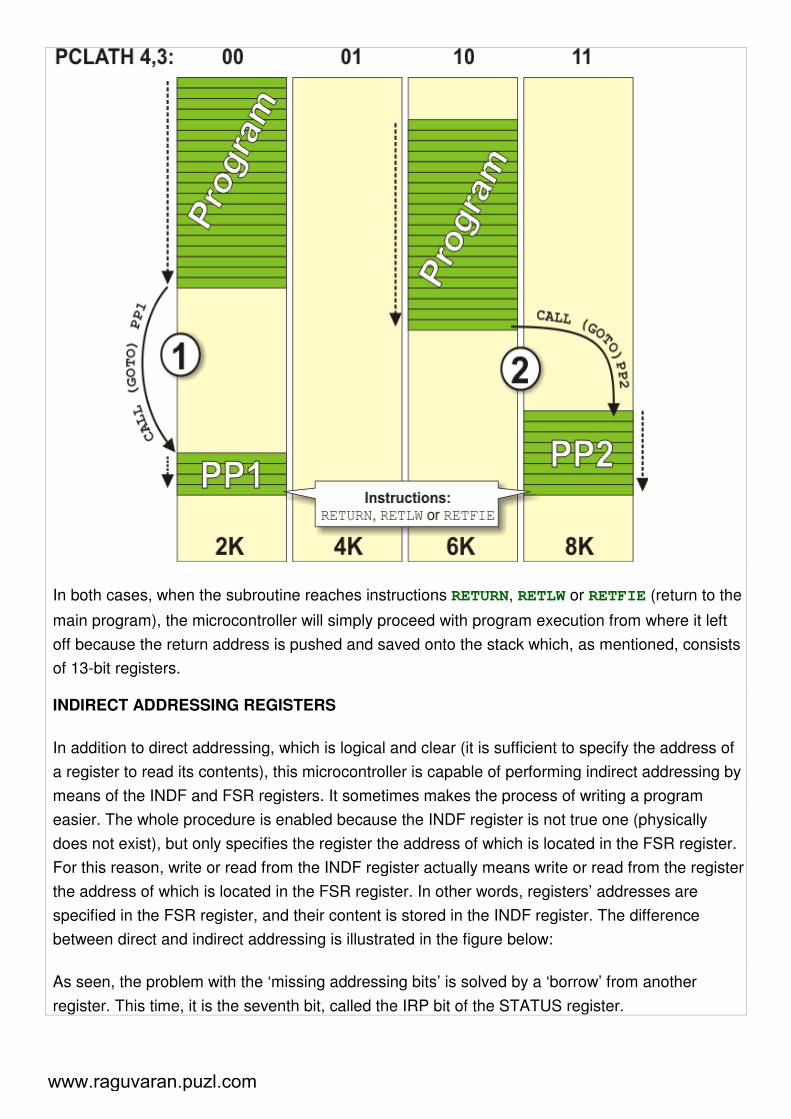
In both cases, when the subroutine reaches instructions RETURN, RETLW or RETFIE (return to the
main program), the microcontroller will simply proceed with program execution from where it left
off because the return address is pushed and saved onto the stack which, as mentioned, consists
of 13-bit registers.
INDIRECT ADDRESSING REGISTERS
In addition to direct addressing, which is logical and clear (it is sufficient to specify the address of
a register to read its contents), this microcontroller is capable of performing indirect addressing by
means of the INDF and FSR registers. It sometimes makes the process of writing a program
easier. The whole procedure is enabled because the INDF register is not true one (physically
does not exist), but only specifies the register the address of which is located in the FSR register.
For this reason, write or read from the INDF register actually means write or read from the register
the address of which is located in the FSR register. In other words, registers’ addresses are
specified in the FSR register, and their content is stored in the INDF register. The difference
between direct and indirect addressing is illustrated in the figure below:
As seen, the problem with the ‘missing addressing bits’ is solved by a ‘borrow’ from another
register. This time, it is the seventh bit, called the IRP bit of the STATUS register.
www.raguvaran.puzl.com
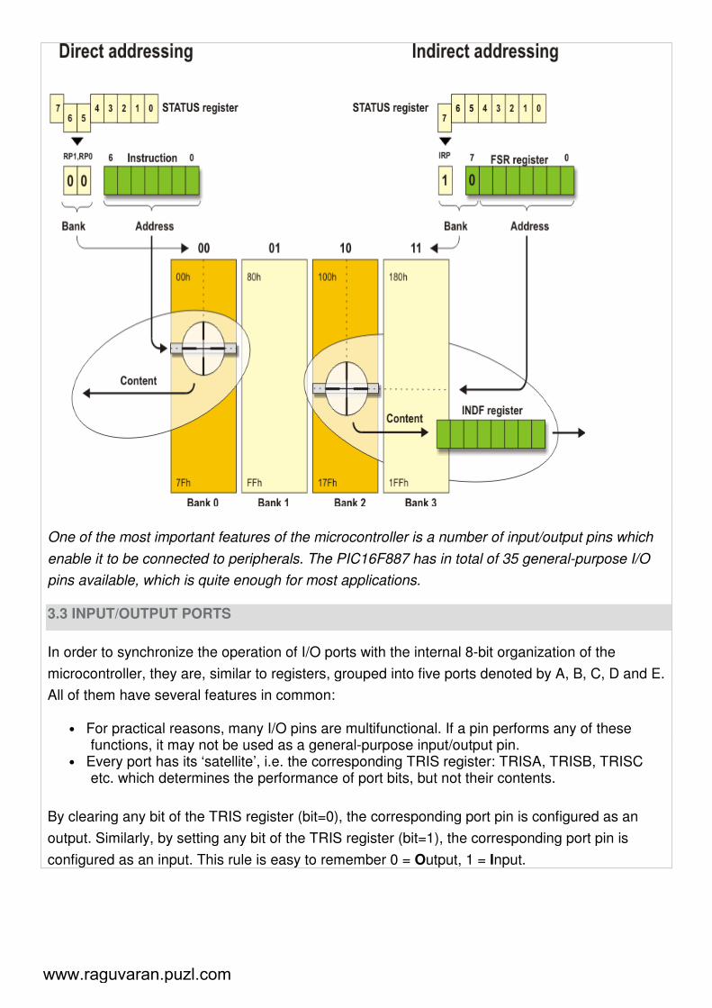
One of the most important features of the microcontroller is a number of input/output pins which
enable it to be connected to peripherals. The PIC16F887 has in total of 35 general-purpose I/O
pins available, which is quite enough for most applications.
3.3 INPUT/OUTPUT PORTS
In order to synchronize the operation of I/O ports with the internal 8-bit organization of the
microcontroller, they are, similar to registers, grouped into five ports denoted by A, B, C, D and E.
All of them have several features in common:
• For practical reasons, many I/O pins are multifunctional. If a pin performs any of these functions, it may not be used as a general-purpose input/output pin.
• Every port has its ‘satellite’, i.e. the corresponding TRIS register: TRISA, TRISB, TRISC etc. which determines the performance of port bits, but not their contents.
By clearing any bit of the TRIS register (bit=0), the corresponding port pin is configured as an
output. Similarly, by setting any bit of the TRIS register (bit=1), the corresponding port pin is
configured as an input. This rule is easy to remember 0 = Output, 1 = Input.
www.raguvaran.puzl.com
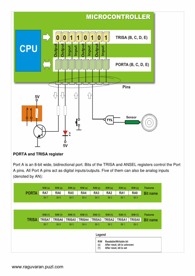
PORTA and TRISA register
Port A is an 8-bit wide, bidirectional port. Bits of the TRISA and ANSEL registers control the Port
A pins. All Port A pins act as digital inputs/outputs. Five of them can also be analog inputs
(denoted by AN):
www.raguvaran.puzl.com
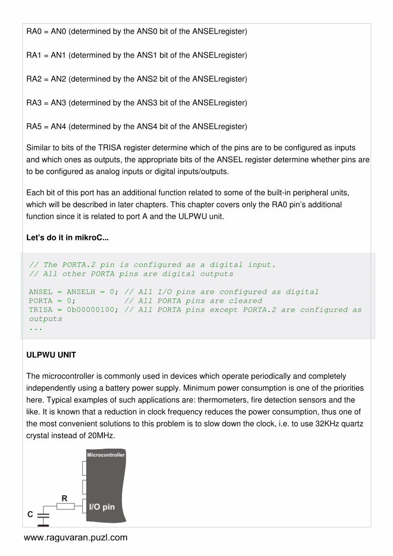
RA0 = AN0 (determined by the ANS0 bit of the ANSELregister)
RA1 = AN1 (determined by the ANS1 bit of the ANSELregister)
RA2 = AN2 (determined by the ANS2 bit of the ANSELregister)
RA3 = AN3 (determined by the ANS3 bit of the ANSELregister)
RA5 = AN4 (determined by the ANS4 bit of the ANSELregister)
Similar to bits of the TRISA register determine which of the pins are to be configured as inputs
and which ones as outputs, the appropriate bits of the ANSEL register determine whether pins are
to be configured as analog inputs or digital inputs/outputs.
Each bit of this port has an additional function related to some of the built-in peripheral units,
which will be described in later chapters. This chapter covers only the RA0 pin’s additional
function since it is related to port A and the ULPWU unit.
Let's do it in mikroC...
// The PORTA.2 pin is configured as a digital input.
// All other PORTA pins are digital outputs
ANSEL = ANSELH = 0; // All I/O pins are configured as digital
PORTA = 0; // All PORTA pins are cleared
TRISA = 0b00000100; // All PORTA pins except PORTA.2 are configured as
outputs
...
ULPWU UNIT
The microcontroller is commonly used in devices which operate periodically and completely
independently using a battery power supply. Minimum power consumption is one of the priorities
here. Typical examples of such applications are: thermometers, fire detection sensors and the
like. It is known that a reduction in clock frequency reduces the power consumption, thus one of
the most convenient solutions to this problem is to slow down the clock, i.e. to use 32KHz quartz
crystal instead of 20MHz.
www.raguvaran.puzl.com
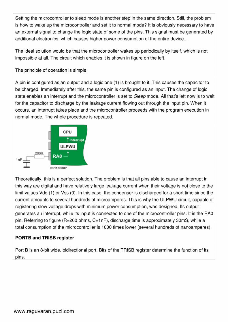
Setting the microcontroller to sleep mode is another step in the same direction. Still, the problem
is how to wake up the microcontroller and set it to normal mode? It is obviously necessary to have
an external signal to change the logic state of some of the pins. This signal must be generated by
additional electronics, which causes higher power consumption of the entire device...
The ideal solution would be that the microcontroller wakes up periodically by itself, which is not
impossible at all. The circuit which enables it is shown in figure on the left.
The principle of operation is simple:
A pin is configured as an output and a logic one (1) is brought to it. This causes the capacitor to
be charged. Immediately after this, the same pin is configured as an input. The change of logic
state enables an interrupt and the microcontroller is set to Sleep mode. All that’s left now is to wait
for the capacitor to discharge by the leakage current flowing out through the input pin. When it
occurs, an interrupt takes place and the microcontroller proceeds with the program execution in
normal mode. The whole procedure is repeated.
Theoretically, this is a perfect solution. The problem is that all pins able to cause an interrupt in
this way are digital and have relatively large leakage current when their voltage is not close to the
limit values Vdd (1) or Vss (0). In this case, the condenser is discharged for a short time since the
current amounts to several hundreds of microamperes. This is why the ULPWU circuit, capable of
registering slow voltage drops with minimum power consumption, was designed. Its output
generates an interrupt, while its input is connected to one of the microcontroller pins. It is the RA0
pin. Referring to figure (R=200 ohms, C=1nF), discharge time is approximately 30mS, while a
total consumption of the microcontroller is 1000 times lower (several hundreds of nanoamperes).
PORTB and TRISB register
Port B is an 8-bit wide, bidirectional port. Bits of the TRISB register determine the function of its
pins.
www.raguvaran.puzl.com
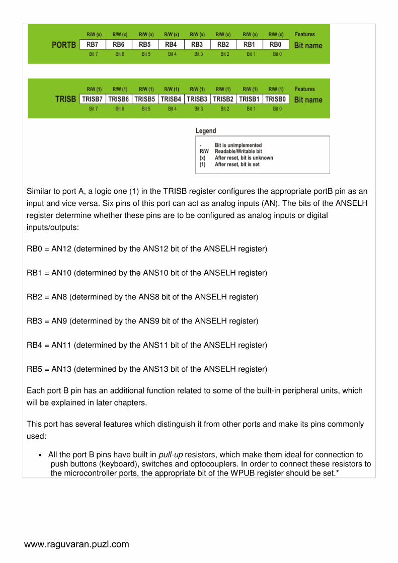
Similar to port A, a logic one (1) in the TRISB register configures the appropriate portB pin as an
input and vice versa. Six pins of this port can act as analog inputs (AN). The bits of the ANSELH
register determine whether these pins are to be configured as analog inputs or digital
inputs/outputs:
RB0 = AN12 (determined by the ANS12 bit of the ANSELH register)
RB1 = AN10 (determined by the ANS10 bit of the ANSELH register)
RB2 = AN8 (determined by the ANS8 bit of the ANSELH register)
RB3 = AN9 (determined by the ANS9 bit of the ANSELH register)
RB4 = AN11 (determined by the ANS11 bit of the ANSELH register)
RB5 = AN13 (determined by the ANS13 bit of the ANSELH register)
Each port B pin has an additional function related to some of the built-in peripheral units, which
will be explained in later chapters.
This port has several features which distinguish it from other ports and make its pins commonly
used:
• All the port B pins have built in pull-up resistors, which make them ideal for connection to push buttons (keyboard), switches and optocouplers. In order to connect these resistors to the microcontroller ports, the appropriate bit of the WPUB register should be set.*
www.raguvaran.puzl.com
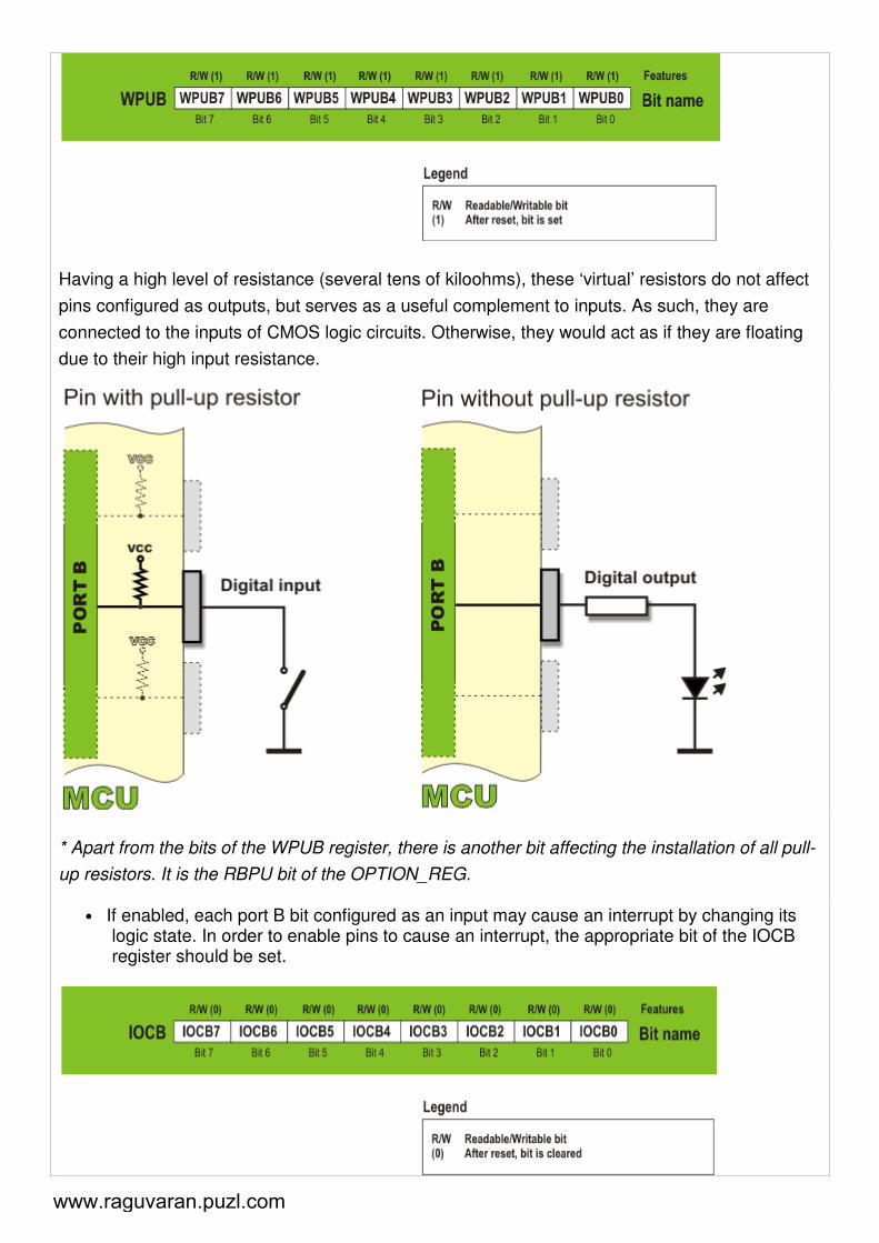
Having a high level of resistance (several tens of kiloohms), these ‘virtual’ resistors do not affect
pins configured as outputs, but serves as a useful complement to inputs. As such, they are
connected to the inputs of CMOS logic circuits. Otherwise, they would act as if they are floating
due to their high input resistance.
* Apart from the bits of the WPUB register, there is another bit affecting the installation of all pull-
up resistors. It is the RBPU bit of the OPTION_REG.
• If enabled, each port B bit configured as an input may cause an interrupt by changing its logic state. In order to enable pins to cause an interrupt, the appropriate bit of the IOCB register should be set.
www.raguvaran.puzl.com
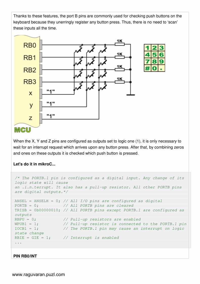
Thanks to these features, the port B pins are commonly used for checking push buttons on the
keyboard because they unerringly register any button press. Thus, there is no need to ‘scan’
these inputs all the time.
When the X, Y and Z pins are configured as outputs set to logic one (1), it is only necessary to
wait for an interrupt request which arrives upon any button press. After that, by combining zeros
and ones on these outputs it is checked which push button is pressed.
Let's do it in mikroC...
/* The PORTB.1 pin is configured as a digital input. Any change of its
logic state will cause
an .i.n.terrupt. It also has a pull-up resistor. All other PORTB pins
are digital outputs.*/
ANSEL = ANSELH = 0; // All I/O pins are configured as digital
PORTB = 0; // All PORTB pins are cleared
TRISB = 0b00000010; // All PORTB pins except PORTB.1 are configured as
outputs
RBPU = 0; // Pull-up resistors are enabled
WPUB1 = 1; // Pull-up resistor is connected to the PORTB.1 pin
IOCB1 = 1; // The PORTB.1 pin may cause an interrupt on logic
state change
RBIE = GIE = 1; // Interrupt is enabled
...
PIN RB0/INT
www.raguvaran.puzl.com
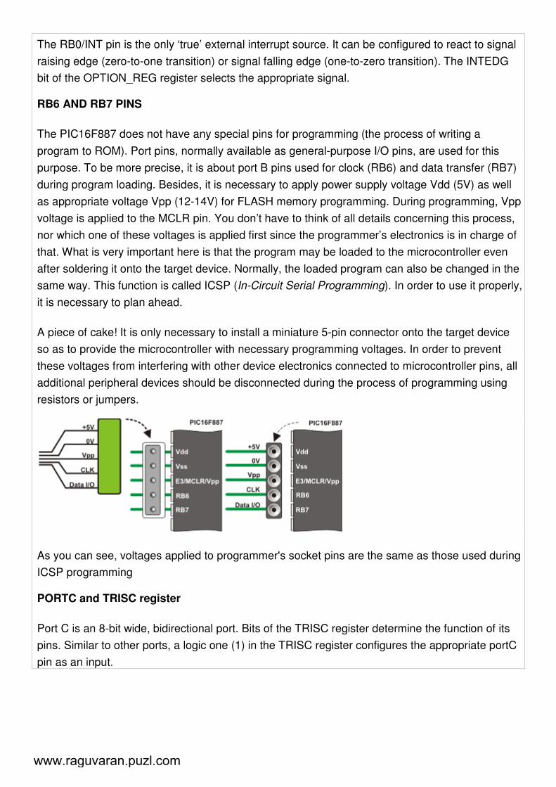
The RB0/INT pin is the only ‘true’ external interrupt source. It can be configured to react to signal
raising edge (zero-to-one transition) or signal falling edge (one-to-zero transition). The INTEDG
bit of the OPTION_REG register selects the appropriate signal.
RB6 AND RB7 PINS
The PIC16F887 does not have any special pins for programming (the process of writing a
program to ROM). Port pins, normally available as general-purpose I/O pins, are used for this
purpose. To be more precise, it is about port B pins used for clock (RB6) and data transfer (RB7)
during program loading. Besides, it is necessary to apply power supply voltage Vdd (5V) as well
as appropriate voltage Vpp (12-14V) for FLASH memory programming. During programming, Vpp
voltage is applied to the MCLR pin. You don’t have to think of all details concerning this process,
nor which one of these voltages is applied first since the programmer’s electronics is in charge of
that. What is very important here is that the program may be loaded to the microcontroller even
after soldering it onto the target device. Normally, the loaded program can also be changed in the
same way. This function is called ICSP (In-Circuit Serial Programming). In order to use it properly,
it is necessary to plan ahead.
A piece of cake! It is only necessary to install a miniature 5-pin connector onto the target device
so as to provide the microcontroller with necessary programming voltages. In order to prevent
these voltages from interfering with other device electronics connected to microcontroller pins, all
additional peripheral devices should be disconnected during the process of programming using
resistors or jumpers.
As you can see, voltages applied to programmer's socket pins are the same as those used during
ICSP programming
PORTC and TRISC register
Port C is an 8-bit wide, bidirectional port. Bits of the TRISC register determine the function of its
pins. Similar to other ports, a logic one (1) in the TRISC register configures the appropriate portC
pin as an input.
www.raguvaran.puzl.com
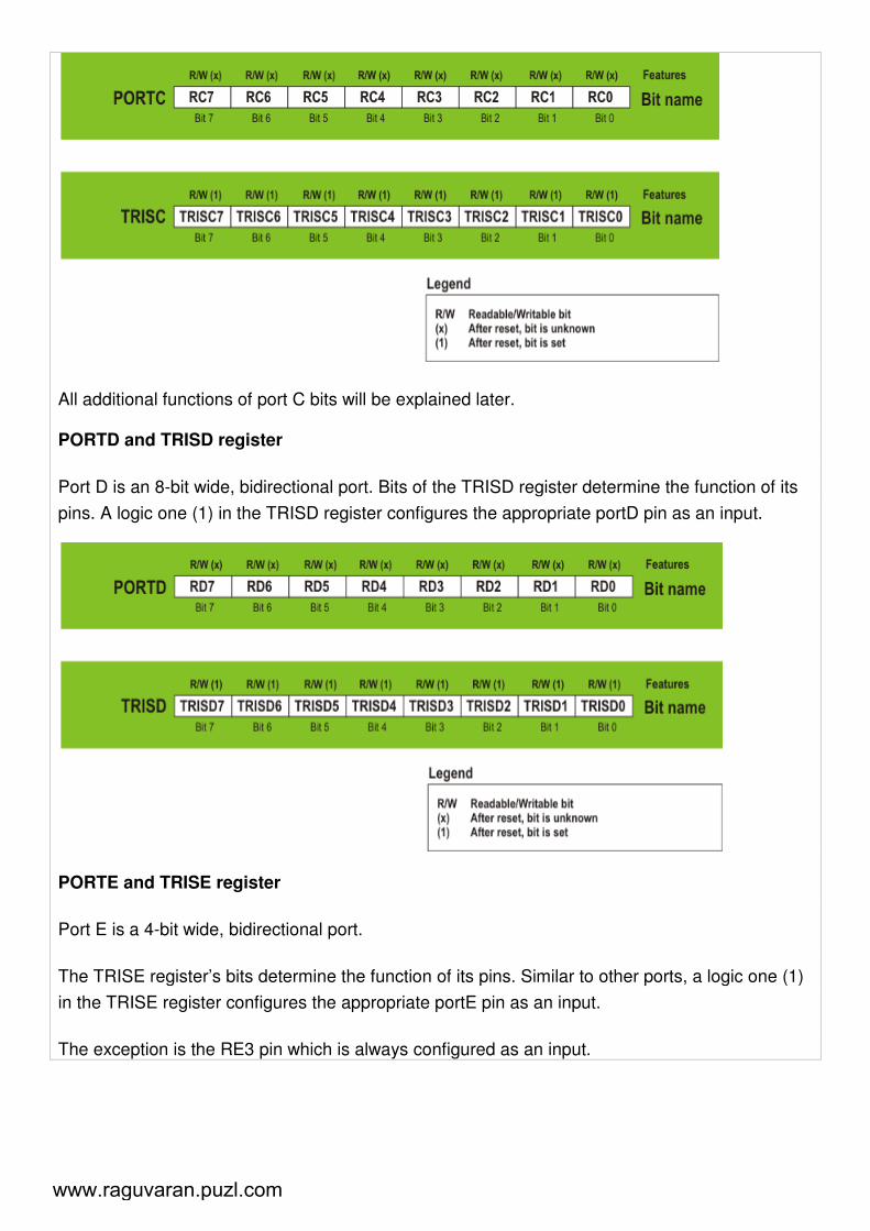
All additional functions of port C bits will be explained later.
PORTD and TRISD register
Port D is an 8-bit wide, bidirectional port. Bits of the TRISD register determine the function of its
pins. A logic one (1) in the TRISD register configures the appropriate portD pin as an input.
PORTE and TRISE register
Port E is a 4-bit wide, bidirectional port.
The TRISE register’s bits determine the function of its pins. Similar to other ports, a logic one (1)
in the TRISE register configures the appropriate portE pin as an input.
The exception is the RE3 pin which is always configured as an input.
www.raguvaran.puzl.com
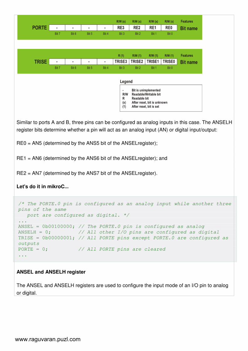
Similar to ports A and B, three pins can be configured as analog inputs in this case. The ANSELH
register bits determine whether a pin will act as an analog input (AN) or digital input/output:
RE0 = AN5 (determined by the ANS5 bit of the ANSELregister);
RE1 = AN6 (determined by the ANS6 bit of the ANSELregister); and
RE2 = AN7 (determined by the ANS7 bit of the ANSELregister).
Let's do it in mikroC...
/* The PORTE.0 pin is configured as an analog input while another three
pins of the same
port are configured as digital. */
...
ANSEL = 0b00100000; // The PORTE.0 pin is configured as analog
ANSELH = 0; // All other I/O pins are configured as digital
TRISE = 0b00000001; // All PORTE pins except PORTE.0 are configured as
outputs
PORTE = 0; // All PORTE pins are cleared
...
ANSEL and ANSELH register
The ANSEL and ANSELH registers are used to configure the input mode of an I/O pin to analog
or digital.
www.raguvaran.puzl.com
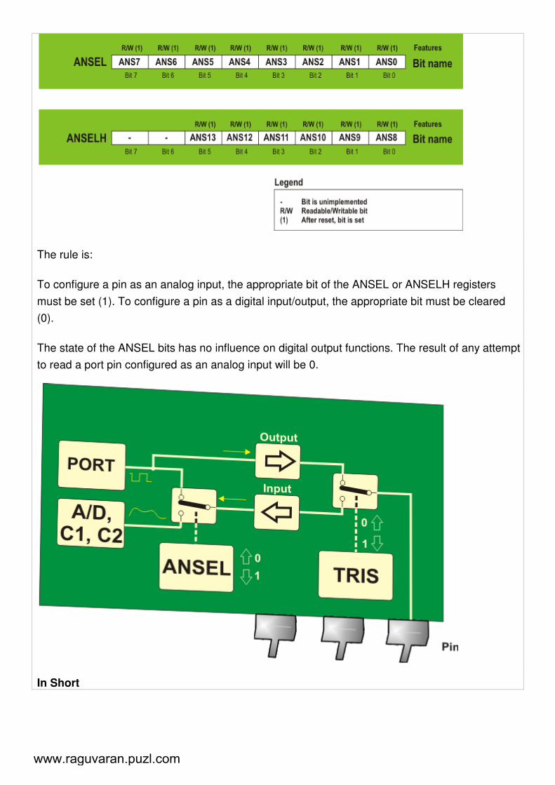
The rule is:
To configure a pin as an analog input, the appropriate bit of the ANSEL or ANSELH registers
must be set (1). To configure a pin as a digital input/output, the appropriate bit must be cleared
(0).
The state of the ANSEL bits has no influence on digital output functions. The result of any attempt
to read a port pin configured as an analog input will be 0.
In Short
www.raguvaran.puzl.com
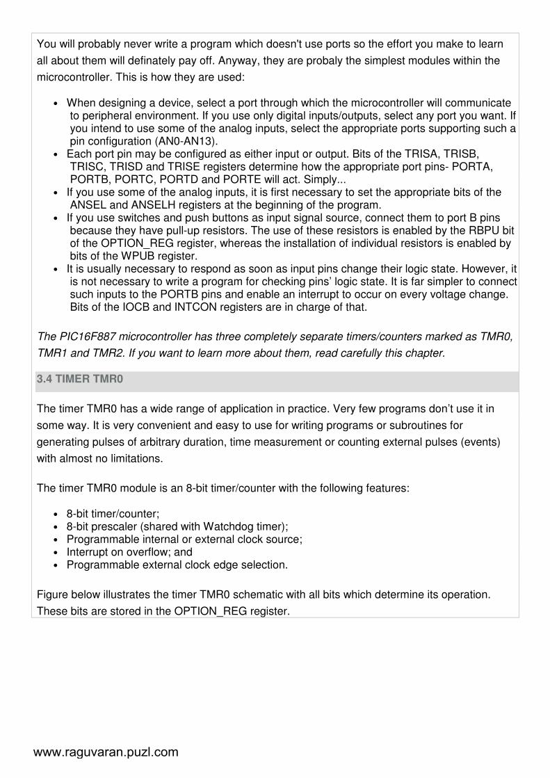
You will probably never write a program which doesn't use ports so the effort you make to learn
all about them will definately pay off. Anyway, they are probaly the simplest modules within the
microcontroller. This is how they are used:
• When designing a device, select a port through which the microcontroller will communicate to peripheral environment. If you use only digital inputs/outputs, select any port you want. If you intend to use some of the analog inputs, select the appropriate ports supporting such a pin configuration (AN0-AN13).
• Each port pin may be configured as either input or output. Bits of the TRISA, TRISB, TRISC, TRISD and TRISE registers determine how the appropriate port pins- PORTA, PORTB, PORTC, PORTD and PORTE will act. Simply...
• If you use some of the analog inputs, it is first necessary to set the appropriate bits of the ANSEL and ANSELH registers at the beginning of the program.
• If you use switches and push buttons as input signal source, connect them to port B pins because they have pull-up resistors. The use of these resistors is enabled by the RBPU bit of the OPTION_REG register, whereas the installation of individual resistors is enabled by bits of the WPUB register.
• It is usually necessary to respond as soon as input pins change their logic state. However, it is not necessary to write a program for checking pins’ logic state. It is far simpler to connect such inputs to the PORTB pins and enable an interrupt to occur on every voltage change. Bits of the IOCB and INTCON registers are in charge of that.
The PIC16F887 microcontroller has three completely separate timers/counters marked as TMR0,
TMR1 and TMR2. If you want to learn more about them, read carefully this chapter.
3.4 TIMER TMR0
The timer TMR0 has a wide range of application in practice. Very few programs don’t use it in
some way. It is very convenient and easy to use for writing programs or subroutines for
generating pulses of arbitrary duration, time measurement or counting external pulses (events)
with almost no limitations.
The timer TMR0 module is an 8-bit timer/counter with the following features:
• 8-bit timer/counter; • 8-bit prescaler (shared with Watchdog timer); • Programmable internal or external clock source; • Interrupt on overflow; and • Programmable external clock edge selection.
Figure below illustrates the timer TMR0 schematic with all bits which determine its operation.
These bits are stored in the OPTION_REG register.
www.raguvaran.puzl.com
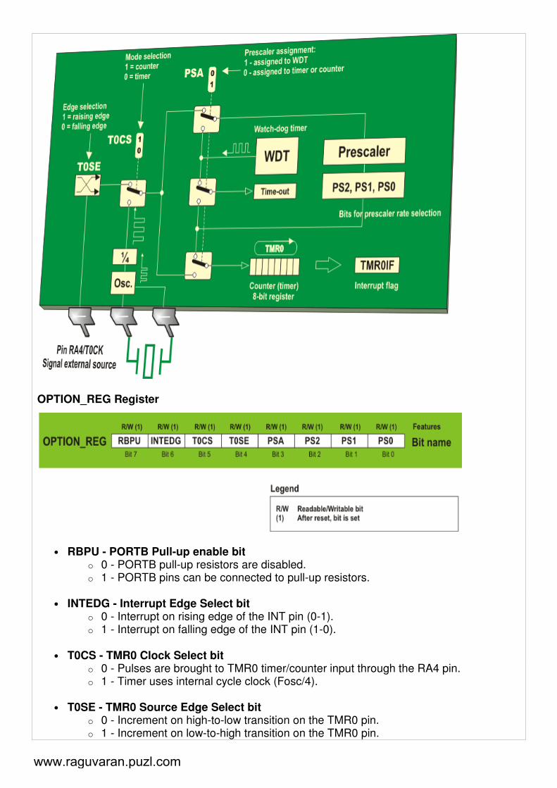
OPTION_REG Register
• RBPU - PORTB Pull-up enable bit o 0 - PORTB pull-up resistors are disabled. o 1 - PORTB pins can be connected to pull-up resistors.
• INTEDG - Interrupt Edge Select bit o 0 - Interrupt on rising edge of the INT pin (0-1). o 1 - Interrupt on falling edge of the INT pin (1-0).
• T0CS - TMR0 Clock Select bit o 0 - Pulses are brought to TMR0 timer/counter input through the RA4 pin. o 1 - Timer uses internal cycle clock (Fosc/4).
• T0SE - TMR0 Source Edge Select bit o 0 - Increment on high-to-low transition on the TMR0 pin. o 1 - Increment on low-to-high transition on the TMR0 pin.
www.raguvaran.puzl.com
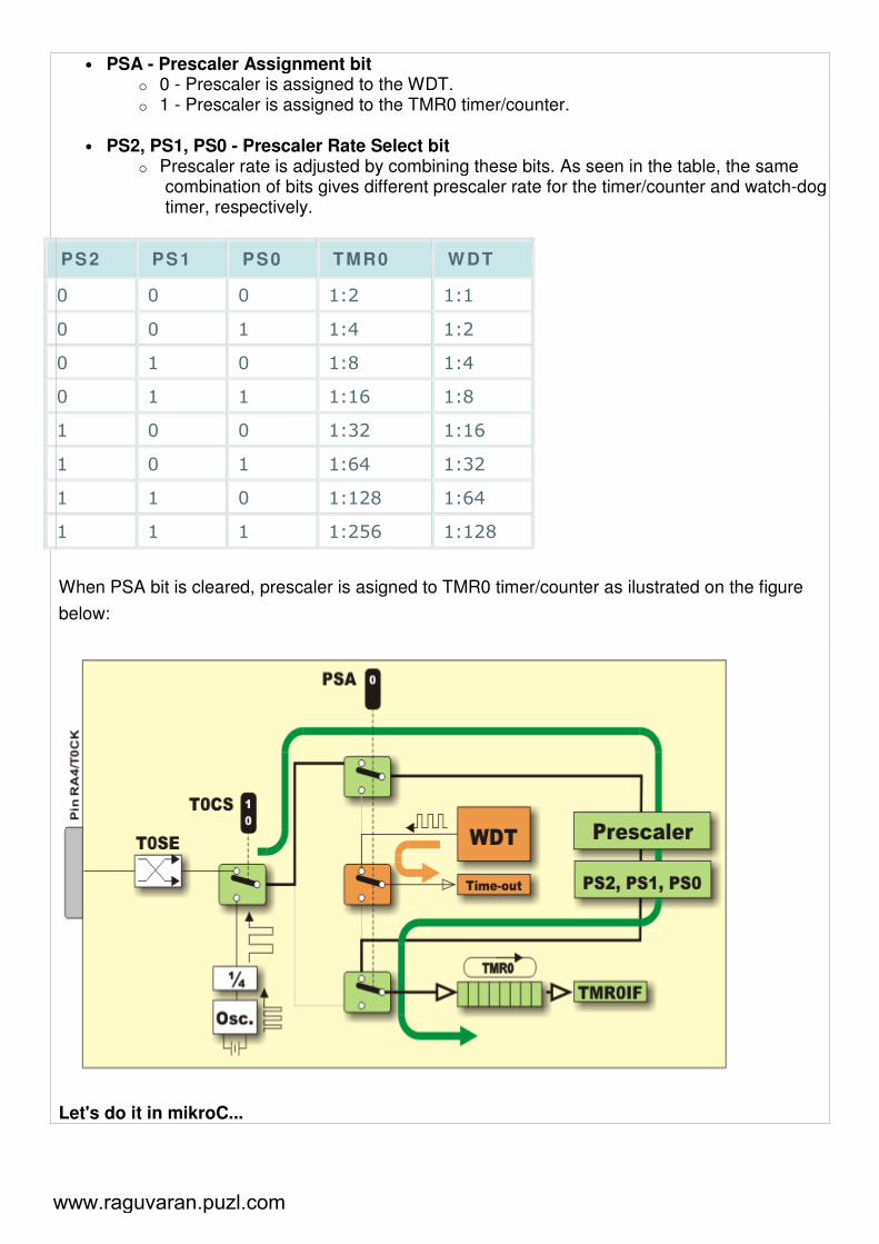
• PSA - Prescaler Assignment bit o 0 - Prescaler is assigned to the WDT. o 1 - Prescaler is assigned to the TMR0 timer/counter.
• PS2, PS1, PS0 - Prescaler Rate Select bit o Prescaler rate is adjusted by combining these bits. As seen in the table, the same
combination of bits gives different prescaler rate for the timer/counter and watch-dog timer, respectively.
PS2 PS1 PS0 TMR0 WDT
0 0 0 1:2 1:1
0 0 1 1:4 1:2
0 1 0 1:8 1:4
0 1 1 1:16 1:8
1 0 0 1:32 1:16
1 0 1 1:64 1:32
1 1 0 1:128 1:64
1 1 1 1:256 1:128
When PSA bit is cleared, prescaler is asigned to TMR0 timer/counter as ilustrated on the figure
below:
Let's do it in mikroC...
www.raguvaran.puzl.com
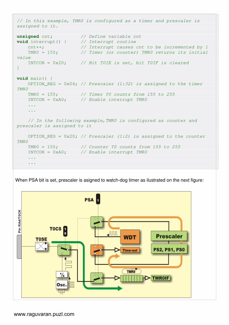
// In this example, TMR0 is configured as a timer and prescaler is
assigned to it.
unsigned cnt; // Define variable cnt
void interrupt() // Interrupt routine
cnt++; // Interrupt causes cnt to be incremented by 1
TMR0 = 155; // Timer (or counter) TMR0 returns its initial
value
INTCON = 0x20; // Bit T0IE is set, bit T0IF is cleared
void main()
OPTION_REG = 0x04; // Prescaler (1:32) is assigned to the timer
TMR0
TMR0 = 155; // Timer T0 counts from 155 to 255
INTCON = 0xA0; // Enable interrupt TMR0
...
...
// In the following example,TMR0 is configured as counter and
prescaler is assigned to it
OPTION_REG = 0x20; // Prescaler (1:2) is assigned to the counter
TMR0
TMR0 = 155; // Counter T0 counts from 155 to 255
INTCON = 0xA0; // Enable interrupt TMR0
...
...
When PSA bit is set, prescaler is asigned to watch-dog timer as ilustrated on the next figure:
www.raguvaran.puzl.com
Let's do it in mikroC...
// In this example, prescaler (1:64) is assigned to Watch-dog timer.
void main()
OPTION_REG = 0x0E; // Prescaler is assigned to WDT (1:64)
asm CLRWDT; // Assembly command to reset WDT
...
...
asm CLRWDT; // Assembly command to reset WDT
...
Additionally it is also worth mentioning:
• When the prescaler is assigned to the timer/counter, any write to the TMR0 register will clear the prescaler.
• When the prescaler is assigned to the watch-dog timer, the CLRWDT instruction will clear both the prescaler and WDT.
• Write to the TMR0 register, used as timer, will not cause the pulse counting to start immediately, but with two instruction cycles delay. Accordingly, it is necessary to adjust the value written to the TMR0 register.
• When the microcontroller is set in sleep mode, the clock oscillator is turned off. Overflow cannot occur since there are no pulses to count. This is why the TMR0 overflow interrupt cannot wake up the processor from Sleep mode.
• When used as an external clock counter, without prescaler, a minimal pulse length or a delay between two pulses must be 2 Tosc + 20 nS (Tosc is the oscillator clock signal period).
• When used as an external clock counter with prescaler, a minimal pulse length or interval between two pulses is only 10nS.
• The 8-bit prescaler register is not available to the user, which means that it cannot be directly read or written to.
• When changing the prescaler assignment from TMR0 to the watch-dog timer, the following instruction sequence written in assembly language must be executed in order to prevent the microcontroller from reset:
BANKSEL TMR0
CLRWDT ;CLEAR WDT
CLRF TMR0 ;CLEAR TMR0 AND PRESCALER
BANKSEL OPTION_REG
BSF OPTION_REG,PSA ;PRESCALER IS ASSIGNED TO WDT
CLRWDT ;CLEAR WDT
MOVLW b'11111000' ;SELECT BITS PS2,PS1,PS0 AND CLEAR
ANDWF OPTION_REG,W ;THEM BY 'LOGIC AND' INSTRUCTION
IORLW b'00000101' ;BITS PS2, PS1, AND PS0 SET
MOVWF OPTION_REG ;PRESCALER RATE TO 1:32
• Likewise, when changing the prescaler assignment from the WDT to TMR0, the following instruction sequence, also written in assembly language, must be executed:
www.raguvaran.puzl.com
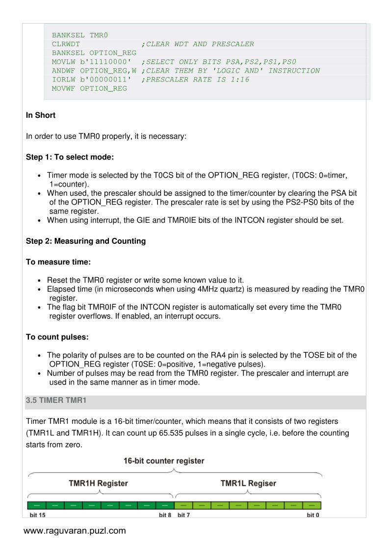
BANKSEL TMR0
CLRWDT ;CLEAR WDT AND PRESCALER
BANKSEL OPTION_REG
MOVLW b'11110000' ;SELECT ONLY BITS PSA,PS2,PS1,PS0
ANDWF OPTION_REG,W ;CLEAR THEM BY 'LOGIC AND' INSTRUCTION
IORLW b'00000011' ;PRESCALER RATE IS 1:16
MOVWF OPTION_REG
In Short
In order to use TMR0 properly, it is necessary:
Step 1: To select mode:
• Timer mode is selected by the T0CS bit of the OPTION_REG register, (T0CS: 0=timer, 1=counter).
• When used, the prescaler should be assigned to the timer/counter by clearing the PSA bit of the OPTION_REG register. The prescaler rate is set by using the PS2-PS0 bits of the same register.
• When using interrupt, the GIE and TMR0IE bits of the INTCON register should be set.
Step 2: Measuring and Counting
To measure time:
• Reset the TMR0 register or write some known value to it. • Elapsed time (in microseconds when using 4MHz quartz) is measured by reading the TMR0
register. • The flag bit TMR0IF of the INTCON register is automatically set every time the TMR0
register overflows. If enabled, an interrupt occurs.
To count pulses:
• The polarity of pulses are to be counted on the RA4 pin is selected by the TOSE bit of the OPTION_REG register (T0SE: 0=positive, 1=negative pulses).
• Number of pulses may be read from the TMR0 register. The prescaler and interrupt are used in the same manner as in timer mode.
3.5 TIMER TMR1
Timer TMR1 module is a 16-bit timer/counter, which means that it consists of two registers
(TMR1L and TMR1H). It can count up 65.535 pulses in a single cycle, i.e. before the counting
starts from zero.
www.raguvaran.puzl.com
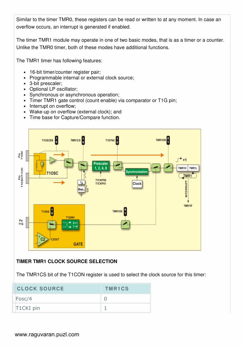
Similar to the timer TMR0, these registers can be read or written to at any moment. In case an
overflow occurs, an interrupt is generated if enabled.
The timer TMR1 module may operate in one of two basic modes, that is as a timer or a counter.
Unlike the TMR0 timer, both of these modes have additional functions.
The TMR1 timer has following features:
• 16-bit timer/counter register pair; • Programmable internal or external clock source; • 3-bit prescaler; • Optional LP oscillator; • Synchronous or asynchronous operation; • Timer TMR1 gate control (count enable) via comparator or T1G pin; • Interrupt on overflow; • Wake-up on overflow (external clock); and • Time base for Capture/Compare function.
TIMER TMR1 CLOCK SOURCE SELECTION
The TMR1CS bit of the T1CON register is used to select the clock source for this timer:
CLOCK SOURCE TMR1CS
Fosc/4 0
T1CKI pin 1
www.raguvaran.puzl.com
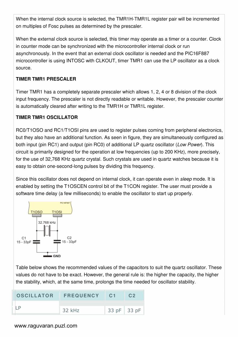
When the internal clock source is selected, the TMR1H-TMR1L register pair will be incremented
on multiples of Fosc pulses as determined by the prescaler.
When the external clock source is selected, this timer may operate as a timer or a counter. Clock
in counter mode can be synchronized with the microcontroller internal clock or run
asynchronously. In the event that an external clock oscillator is needed and the PIC16F887
microcontroller is using INTOSC with CLKOUT, timer TMR1 can use the LP oscillator as a clock
source.
TIMER TMR1 PRESCALER
Timer TMR1 has a completely separate prescaler which allows 1, 2, 4 or 8 division of the clock
input frequency. The prescaler is not directly readable or writable. However, the prescaler counter
is automatically cleared after writing to the TMR1H or TMR1L register.
TIMER TMR1 OSCILLATOR
RC0/T1OSO and RC1/T1OSI pins are used to register pulses coming from peripheral electronics,
but they also have an additional function. As seen in figure, they are simultaneously configured as
both input (pin RC1) and output (pin RC0) of additional LP quartz oscillator (Low Power). This
circuit is primarily designed for the operation at low frequencies (up to 200 KHz), more precisely,
for the use of 32,768 KHz quartz crystal. Such crystals are used in quartz watches because it is
easy to obtain one-second-long pulses by dividing this frequency.
Since this oscillator does not depend on internal clock, it can operate even in sleep mode. It is
enabled by setting the T1OSCEN control bit of the T1CON register. The user must provide a
software time delay (a few milliseconds) to enable the oscillator to start up properly.
Table below shows the recommended values of the capacitors to suit the quartz oscillator. These
values do not have to be exact. However, the general rule is: the higher the capacity, the higher
the stability, which, at the same time, prolongs the time needed for oscillator stability.
OSCILLATOR FREQUENCY C1 C2
LP 32 kHz 33 pF 33 pF
www.raguvaran.puzl.com
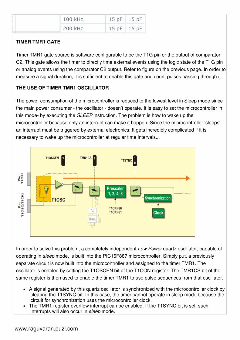
100 kHz 15 pF 15 pF
200 kHz 15 pF 15 pF
TIMER TMR1 GATE
Timer TMR1 gate source is software configurable to be the T1G pin or the output of comparator
C2. This gate allows the timer to directly time external events using the logic state of the T1G pin
or analog events using the comparator C2 output. Refer to figure on the previous page. In order to
measure a signal duration, it is sufficient to enable this gate and count pulses passing through it.
THE USE OF TIMER TMR1 OSCILLATOR
The power consumption of the microcontroller is reduced to the lowest level in Sleep mode since
the main power consumer - the oscillator - doesn’t operate. It is easy to set the microcontroller in
this mode- by executing the SLEEP instruction. The problem is how to wake up the
microcontroller because only an interrupt can make it happen. Since the microcontroller 'sleeps',
an interrupt must be triggered by external electronics. It gets incredibly complicated if it is
necessary to wake up the microcontroller at regular time intervals...
In order to solve this problem, a completely independent Low Power quartz oscillator, capable of
operating in sleep mode, is built into the PIC16F887 microcontroller. Simply put, a previously
separate circuit is now built into the microcontroller and assigned to the timer TMR1. The
oscillator is enabled by setting the T1OSCEN bit of the T1CON register. The TMR1CS bit of the
same register is then used to enable the timer TMR1 to use pulse sequences from that oscillator.
• A signal generated by this quartz oscillator is synchronized with the microcontroller clock by clearing the T1SYNC bit. In this case, the timer cannot operate in sleep mode because the circuit for synchronization uses the microcontroller clock.
• The TMR1 register overflow interrupt can be enabled. If the T1SYNC bit is set, such interrupts will also occur in sleep mode.
www.raguvaran.puzl.com
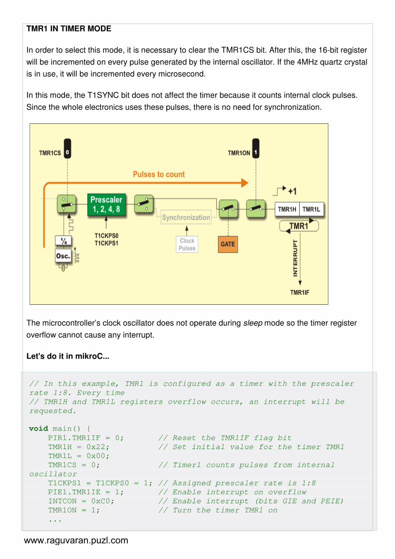
TMR1 IN TIMER MODE
In order to select this mode, it is necessary to clear the TMR1CS bit. After this, the 16-bit register
will be incremented on every pulse generated by the internal oscillator. If the 4MHz quartz crystal
is in use, it will be incremented every microsecond.
In this mode, the T1SYNC bit does not affect the timer because it counts internal clock pulses.
Since the whole electronics uses these pulses, there is no need for synchronization.
The microcontroller’s clock oscillator does not operate during sleep mode so the timer register
overflow cannot cause any interrupt.
Let's do it in mikroC...
// In this example, TMR1 is configured as a timer with the prescaler
rate 1:8. Every time
// TMR1H and TMR1L registers overflow occurs, an interrupt will be
requested.
void main()
PIR1.TMR1IF = 0; // Reset the TMR1IF flag bit
TMR1H = 0x22; // Set initial value for the timer TMR1
TMR1L = 0x00;
TMR1CS = 0; // Timer1 counts pulses from internal
oscillator
T1CKPS1 = T1CKPS0 = 1; // Assigned prescaler rate is 1:8
PIE1.TMR1IE = 1; // Enable interrupt on overflow
INTCON = 0xC0; // Enable interrupt (bits GIE and PEIE)
TMR1ON = 1; // Turn the timer TMR1 on
...
www.raguvaran.puzl.com
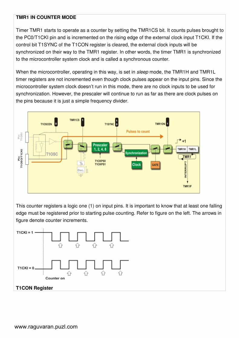
TMR1 IN COUNTER MODE
Timer TMR1 starts to operate as a counter by setting the TMR1CS bit. It counts pulses brought to
the PC0/T1CKI pin and is incremented on the rising edge of the external clock input T1CKI. If the
control bit T1SYNC of the T1CON register is cleared, the external clock inputs will be
synchronized on their way to the TMR1 register. In other words, the timer TMR1 is synchronized
to the microcontroller system clock and is called a synchronous counter.
When the microcontroller, operating in this way, is set in sleep mode, the TMR1H and TMR1L
timer registers are not incremented even though clock pulses appear on the input pins. Since the
microcontroller system clock doesn’t run in this mode, there are no clock inputs to be used for
synchronization. However, the prescaler will continue to run as far as there are clock pulses on
the pins because it is just a simple frequency divider.
This counter registers a logic one (1) on input pins. It is important to know that at least one falling
edge must be registered prior to starting pulse counting. Refer to figure on the left. The arrows in
figure denote counter increments.
T1CON Register
www.raguvaran.puzl.com
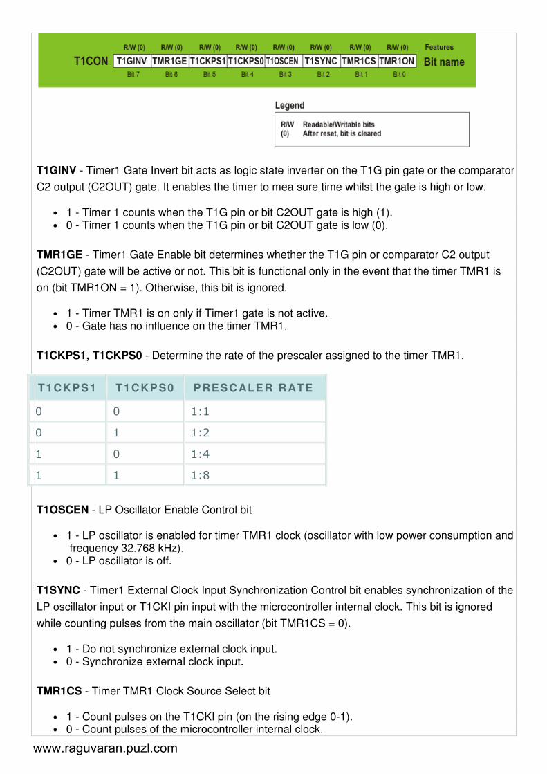
T1GINV - Timer1 Gate Invert bit acts as logic state inverter on the T1G pin gate or the comparator
C2 output (C2OUT) gate. It enables the timer to mea sure time whilst the gate is high or low.
• 1 - Timer 1 counts when the T1G pin or bit C2OUT gate is high (1). • 0 - Timer 1 counts when the T1G pin or bit C2OUT gate is low (0).
TMR1GE - Timer1 Gate Enable bit determines whether the T1G pin or comparator C2 output
(C2OUT) gate will be active or not. This bit is functional only in the event that the timer TMR1 is
on (bit TMR1ON = 1). Otherwise, this bit is ignored.
• 1 - Timer TMR1 is on only if Timer1 gate is not active. • 0 - Gate has no influence on the timer TMR1.
T1CKPS1, T1CKPS0 - Determine the rate of the prescaler assigned to the timer TMR1.
T1CKPS1 T1CKPS0 PRESCALER RAT E
0 0 1:1
0 1 1:2
1 0 1:4
1 1 1:8
T1OSCEN - LP Oscillator Enable Control bit
• 1 - LP oscillator is enabled for timer TMR1 clock (oscillator with low power consumption and frequency 32.768 kHz).
• 0 - LP oscillator is off.
T1SYNC - Timer1 External Clock Input Synchronization Control bit enables synchronization of the
LP oscillator input or T1CKI pin input with the microcontroller internal clock. This bit is ignored
while counting pulses from the main oscillator (bit TMR1CS = 0).
• 1 - Do not synchronize external clock input. • 0 - Synchronize external clock input.
TMR1CS - Timer TMR1 Clock Source Select bit
• 1 - Count pulses on the T1CKI pin (on the rising edge 0-1). • 0 - Count pulses of the microcontroller internal clock.
www.raguvaran.puzl.com
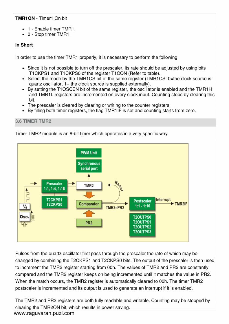
TMR1ON - Timer1 On bit
• 1 - Enable timer TMR1. • 0 - Stop timer TMR1.
In Short
In order to use the timer TMR1 properly, it is necessary to perform the following:
• Since it is not possible to turn off the prescaler, its rate should be adjusted by using bits T1CKPS1 and T1CKPS0 of the register T1CON (Refer to table).
• Select the mode by the TMR1CS bit of the same register (TMR1CS: 0=the clock source is quartz oscillator, 1= the clock source is supplied externally).
• By setting the T1OSCEN bit of the same register, the oscillator is enabled and the TMR1H and TMR1L registers are incremented on every clock input. Counting stops by clearing this bit.
• The prescaler is cleared by clearing or writing to the counter registers. • By filling both timer registers, the flag TMR1IF is set and counting starts from zero.
3.6 TIMER TMR2
Timer TMR2 module is an 8-bit timer which operates in a very specific way.
Pulses from the quartz oscillator first pass through the prescaler the rate of which may be
changed by combining the T2CKPS1 and T2CKPS0 bits. The output of the prescaler is then used
to increment the TMR2 register starting from 00h. The values of TMR2 and PR2 are constantly
compared and the TMR2 register keeps on being incremented until it matches the value in PR2.
When the match occurs, the TMR2 register is automatically cleared to 00h. The timer TMR2
postscaler is incremented and its output is used to generate an interrupt if it is enabled.
The TMR2 and PR2 registers are both fully readable and writable. Counting may be stopped by
clearing the TMR2ON bit, which results in power saving.
www.raguvaran.puzl.com
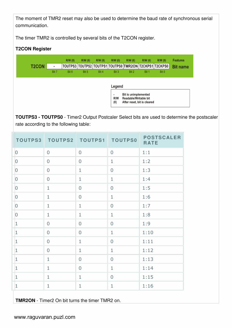
The moment of TMR2 reset may also be used to determine the baud rate of synchronous serial
communication.
The timer TMR2 is controlled by several bits of the T2CON register.
T2CON Register
TOUTPS3 - TOUTPS0 - Timer2 Output Postcaler Select bits are used to determine the postscaler
rate according to the following table:
TOUTPS3 TOUTPS2 TOUTPS1 TOUTPS0 POSTSCALER RATE
0 0 0 0 1:1
0 0 0 1 1:2
0 0 1 0 1:3
0 0 1 1 1:4
0 1 0 0 1:5
0 1 0 1 1:6
0 1 1 0 1:7
0 1 1 1 1:8
1 0 0 0 1:9
1 0 0 1 1:10
1 0 1 0 1:11
1 0 1 1 1:12
1 1 0 0 1:13
1 1 0 1 1:14
1 1 1 0 1:15
1 1 1 1 1:16
TMR2ON - Timer2 On bit turns the timer TMR2 on.
www.raguvaran.puzl.com
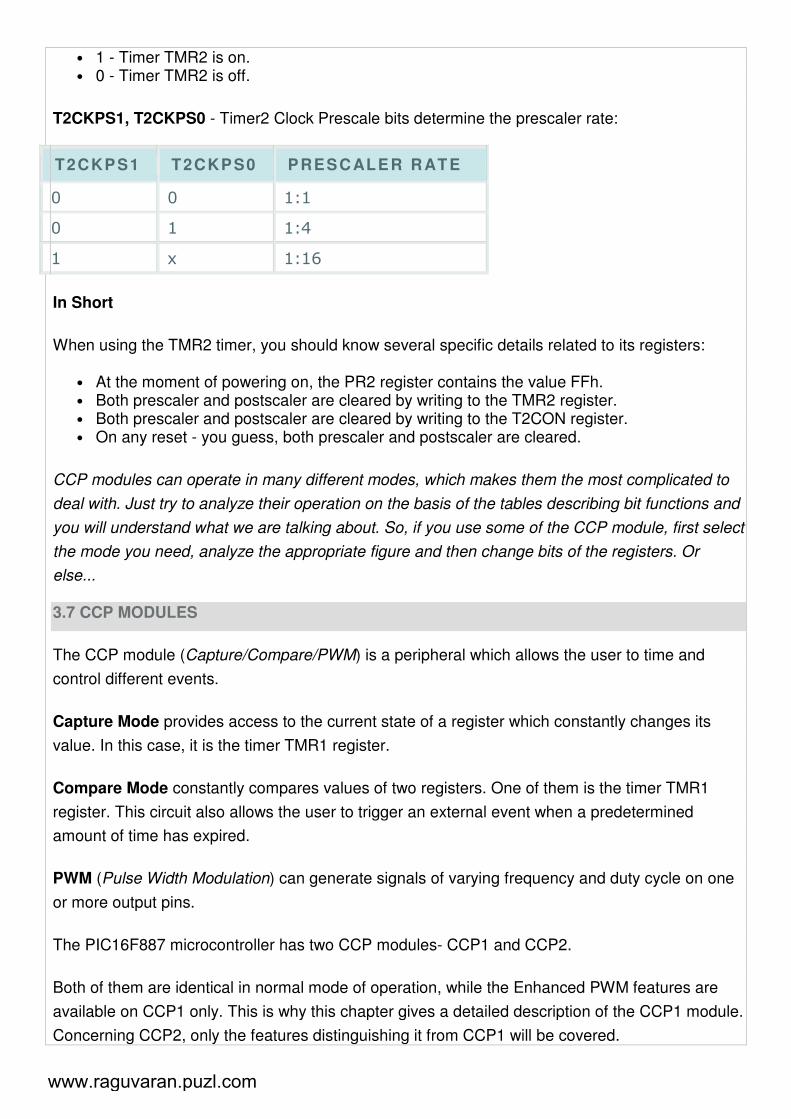
• 1 - Timer TMR2 is on. • 0 - Timer TMR2 is off.
T2CKPS1, T2CKPS0 - Timer2 Clock Prescale bits determine the prescaler rate:
T2CKPS1 T2CKPS0 PRESCALER RAT E
0 0 1:1
0 1 1:4
1 x 1:16
In Short
When using the TMR2 timer, you should know several specific details related to its registers:
• At the moment of powering on, the PR2 register contains the value FFh. • Both prescaler and postscaler are cleared by writing to the TMR2 register. • Both prescaler and postscaler are cleared by writing to the T2CON register. • On any reset - you guess, both prescaler and postscaler are cleared.
CCP modules can operate in many different modes, which makes them the most complicated to
deal with. Just try to analyze their operation on the basis of the tables describing bit functions and
you will understand what we are talking about. So, if you use some of the CCP module, first select
the mode you need, analyze the appropriate figure and then change bits of the registers. Or
else...
3.7 CCP MODULES
The CCP module (Capture/Compare/PWM) is a peripheral which allows the user to time and
control different events.
Capture Mode provides access to the current state of a register which constantly changes its
value. In this case, it is the timer TMR1 register.
Compare Mode constantly compares values of two registers. One of them is the timer TMR1
register. This circuit also allows the user to trigger an external event when a predetermined
amount of time has expired.
PWM (Pulse Width Modulation) can generate signals of varying frequency and duty cycle on one
or more output pins.
The PIC16F887 microcontroller has two CCP modules- CCP1 and CCP2.
Both of them are identical in normal mode of operation, while the Enhanced PWM features are
available on CCP1 only. This is why this chapter gives a detailed description of the CCP1 module.
Concerning CCP2, only the features distinguishing it from CCP1 will be covered.
www.raguvaran.puzl.com
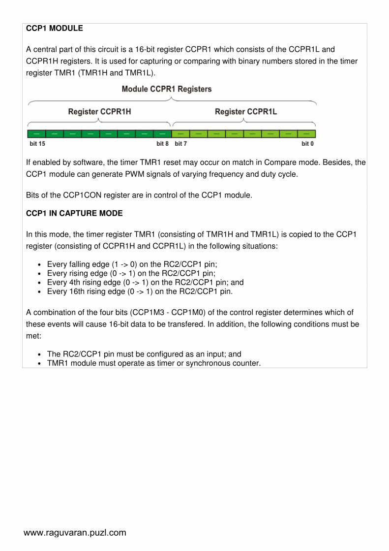
CCP1 MODULE
A central part of this circuit is a 16-bit register CCPR1 which consists of the CCPR1L and
CCPR1H registers. It is used for capturing or comparing with binary numbers stored in the timer
register TMR1 (TMR1H and TMR1L).
If enabled by software, the timer TMR1 reset may occur on match in Compare mode. Besides, the
CCP1 module can generate PWM signals of varying frequency and duty cycle.
Bits of the CCP1CON register are in control of the CCP1 module.
CCP1 IN CAPTURE MODE
In this mode, the timer register TMR1 (consisting of TMR1H and TMR1L) is copied to the CCP1
register (consisting of CCPR1H and CCPR1L) in the following situations:
• Every falling edge (1 -> 0) on the RC2/CCP1 pin; • Every rising edge (0 -> 1) on the RC2/CCP1 pin; • Every 4th rising edge (0 -> 1) on the RC2/CCP1 pin; and • Every 16th rising edge (0 -> 1) on the RC2/CCP1 pin.
A combination of the four bits (CCP1M3 - CCP1M0) of the control register determines which of
these events will cause 16-bit data to be transfered. In addition, the following conditions must be
met:
• The RC2/CCP1 pin must be configured as an input; and • TMR1 module must operate as timer or synchronous counter.
www.raguvaran.puzl.com
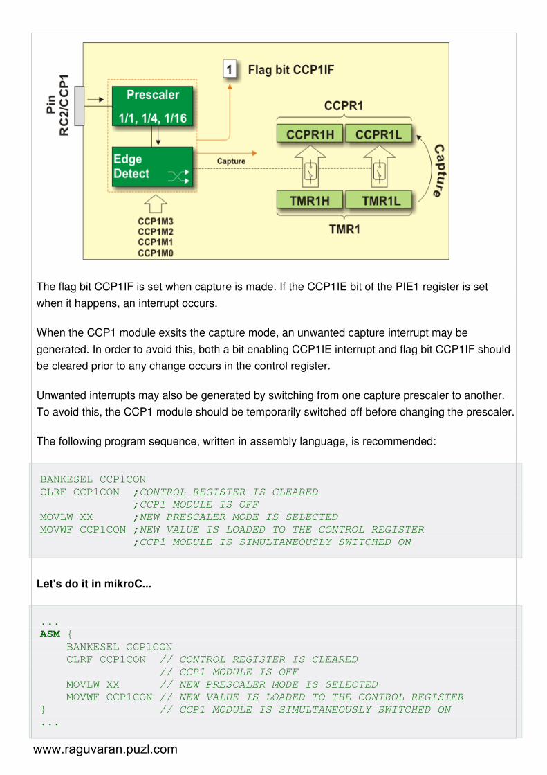
The flag bit CCP1IF is set when capture is made. If the CCP1IE bit of the PIE1 register is set
when it happens, an interrupt occurs.
When the CCP1 module exsits the capture mode, an unwanted capture interrupt may be
generated. In order to avoid this, both a bit enabling CCP1IE interrupt and flag bit CCP1IF should
be cleared prior to any change occurs in the control register.
Unwanted interrupts may also be generated by switching from one capture prescaler to another.
To avoid this, the CCP1 module should be temporarily switched off before changing the prescaler.
The following program sequence, written in assembly language, is recommended:
BANKESEL CCP1CON
CLRF CCP1CON ;CONTROL REGISTER IS CLEARED
;CCP1 MODULE IS OFF
MOVLW XX ;NEW PRESCALER MODE IS SELECTED
MOVWF CCP1CON ;NEW VALUE IS LOADED TO THE CONTROL REGISTER
;CCP1 MODULE IS SIMULTANEOUSLY SWITCHED ON
Let's do it in mikroC...
...
ASM
BANKESEL CCP1CON
CLRF CCP1CON // CONTROL REGISTER IS CLEARED
// CCP1 MODULE IS OFF
MOVLW XX // NEW PRESCALER MODE IS SELECTED
MOVWF CCP1CON // NEW VALUE IS LOADED TO THE CONTROL REGISTER
// CCP1 MODULE IS SIMULTANEOUSLY SWITCHED ON
...
www.raguvaran.puzl.com
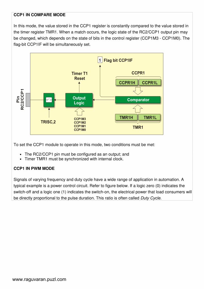
CCP1 IN COMPARE MODE
In this mode, the value stored in the CCP1 register is constantly compared to the value stored in
the timer register TMR1. When a match occurs, the logic state of the RC2/CCP1 output pin may
be changed, which depends on the state of bits in the control register (CCP1M3 - CCP1M0). The
flag-bit CCP1IF will be simultaneously set.
To set the CCP1 module to operate in this mode, two conditions must be met:
• The RC2/CCP1 pin must be configured as an output; and • Timer TMR1 must be synchronized with internal clock.
CCP1 IN PWM MODE
Signals of varying frequency and duty cycle have a wide range of application in automation. A
typical example is a power control circuit. Refer to figure below. If a logic zero (0) indicates the
switch-off and a logic one (1) indicates the switch-on, the electrical power that load consumers will
be directly proportional to the pulse duration. This ratio is often called Duty Cycle.
www.raguvaran.puzl.com
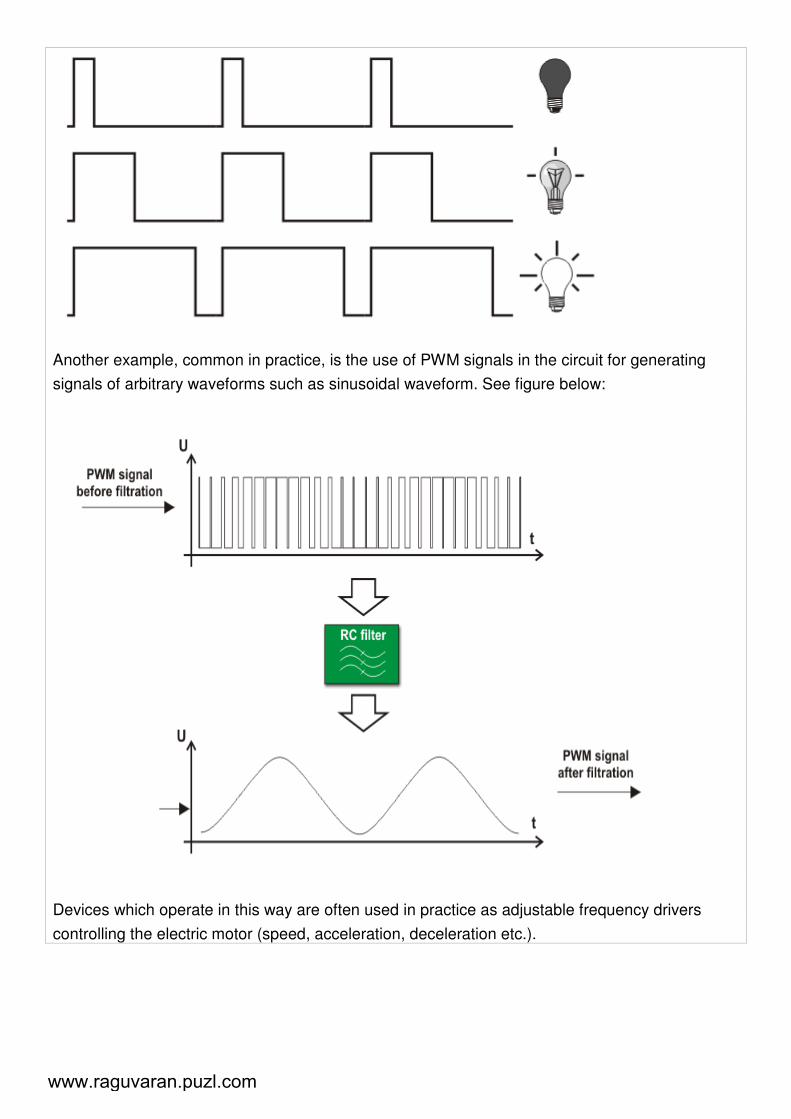
Another example, common in practice, is the use of PWM signals in the circuit for generating
signals of arbitrary waveforms such as sinusoidal waveform. See figure below:
Devices which operate in this way are often used in practice as adjustable frequency drivers
controlling the electric motor (speed, acceleration, deceleration etc.).
www.raguvaran.puzl.com
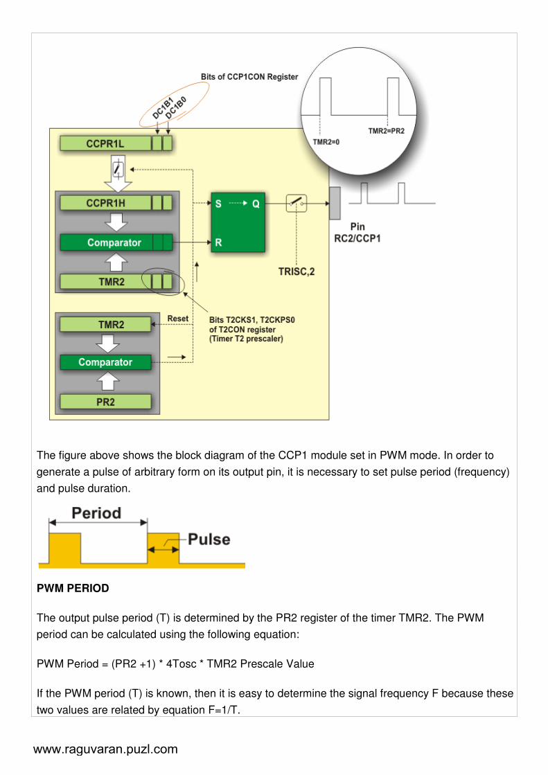
The figure above shows the block diagram of the CCP1 module set in PWM mode. In order to
generate a pulse of arbitrary form on its output pin, it is necessary to set pulse period (frequency)
and pulse duration.
PWM PERIOD
The output pulse period (T) is determined by the PR2 register of the timer TMR2. The PWM
period can be calculated using the following equation:
PWM Period = (PR2 +1) * 4Tosc * TMR2 Prescale Value
If the PWM period (T) is known, then it is easy to determine the signal frequency F because these
two values are related by equation F=1/T.
www.raguvaran.puzl.com
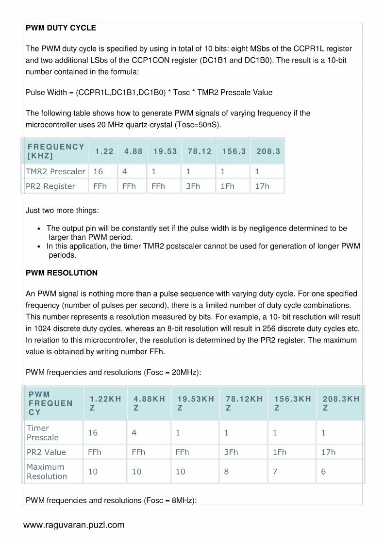
PWM DUTY CYCLE
The PWM duty cycle is specified by using in total of 10 bits: eight MSbs of the CCPR1L register
and two additional LSbs of the CCP1CON register (DC1B1 and DC1B0). The result is a 10-bit
number contained in the formula:
Pulse Width = (CCPR1L,DC1B1,DC1B0) * Tosc * TMR2 Prescale Value
The following table shows how to generate PWM signals of varying frequency if the
microcontroller uses 20 MHz quartz-crystal (Tosc=50nS).
FREQUENCY [KHZ]
1 .22 4 .88 19 .53 78 .12 156 .3 208 .3
TMR2 Prescaler 16 4 1 1 1 1
PR2 Register FFh FFh FFh 3Fh 1Fh 17h
Just two more things:
• The output pin will be constantly set if the pulse width is by negligence determined to be larger than PWM period.
• In this application, the timer TMR2 postscaler cannot be used for generation of longer PWM periods.
PWM RESOLUTION
An PWM signal is nothing more than a pulse sequence with varying duty cycle. For one specified
frequency (number of pulses per second), there is a limited number of duty cycle combinations.
This number represents a resolution measured by bits. For example, a 10- bit resolution will result
in 1024 discrete duty cycles, whereas an 8-bit resolution will result in 256 discrete duty cycles etc.
In relation to this microcontroller, the resolution is determined by the PR2 register. The maximum
value is obtained by writing number FFh.
PWM frequencies and resolutions (Fosc = 20MHz):
PWM FREQUENCY
1 .22KHZ
4 .88KHZ
19 .53KHZ
78 .12KHZ
156 .3KHZ
208 .3KHZ
Timer Prescale
16 4 1 1 1 1
PR2 Value FFh FFh FFh 3Fh 1Fh 17h
Maximum Resolution
10 10 10 8 7 6
PWM frequencies and resolutions (Fosc = 8MHz):
www.raguvaran.puzl.com
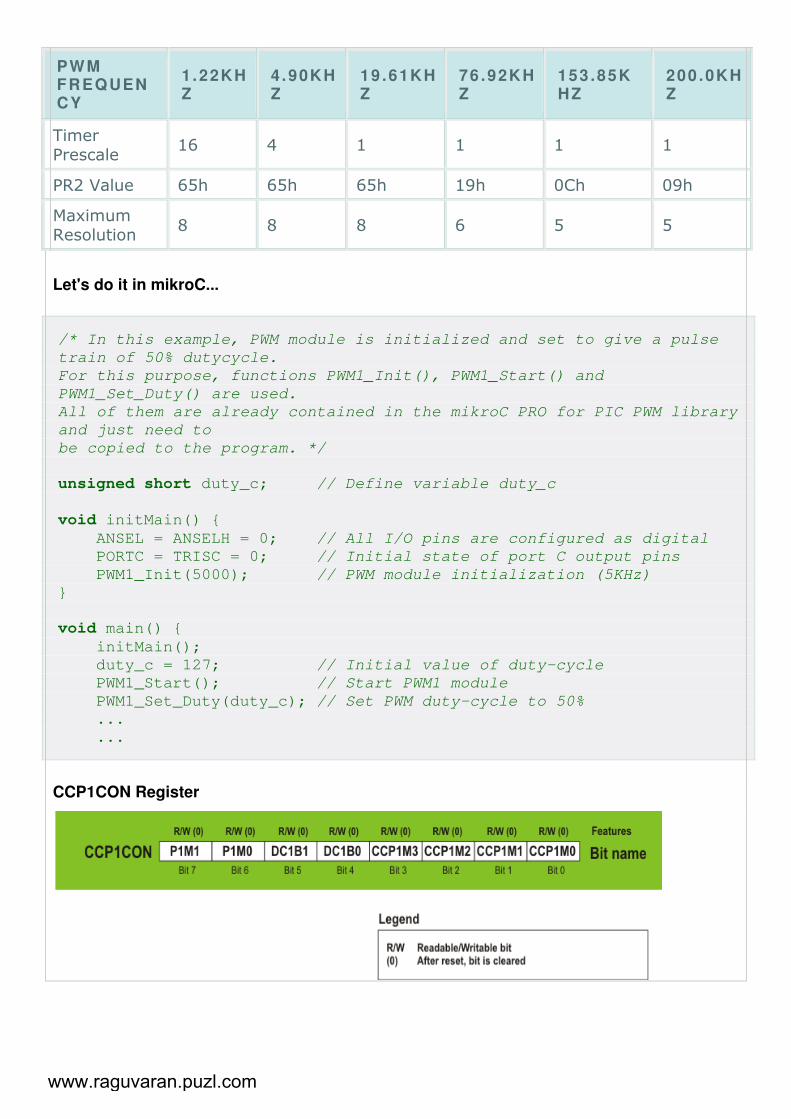
PWM FREQUENCY
1 .22KHZ
4 .90KHZ
19 .61KHZ
76 .92KHZ
153 .85KHZ
200 .0KHZ
Timer Prescale
16 4 1 1 1 1
PR2 Value 65h 65h 65h 19h 0Ch 09h
Maximum Resolution
8 8 8 6 5 5
Let's do it in mikroC...
/* In this example, PWM module is initialized and set to give a pulse
train of 50% dutycycle.
For this purpose, functions PWM1_Init(), PWM1_Start() and
PWM1_Set_Duty() are used.
All of them are already contained in the mikroC PRO for PIC PWM library
and just need to
be copied to the program. */
unsigned short duty_c; // Define variable duty_c
void initMain()
ANSEL = ANSELH = 0; // All I/O pins are configured as digital
PORTC = TRISC = 0; // Initial state of port C output pins
PWM1_Init(5000); // PWM module initialization (5KHz)
void main()
initMain();
duty_c = 127; // Initial value of duty-cycle
PWM1_Start(); // Start PWM1 module
PWM1_Set_Duty(duty_c); // Set PWM duty-cycle to 50%
...
...
CCP1CON Register
www.raguvaran.puzl.com
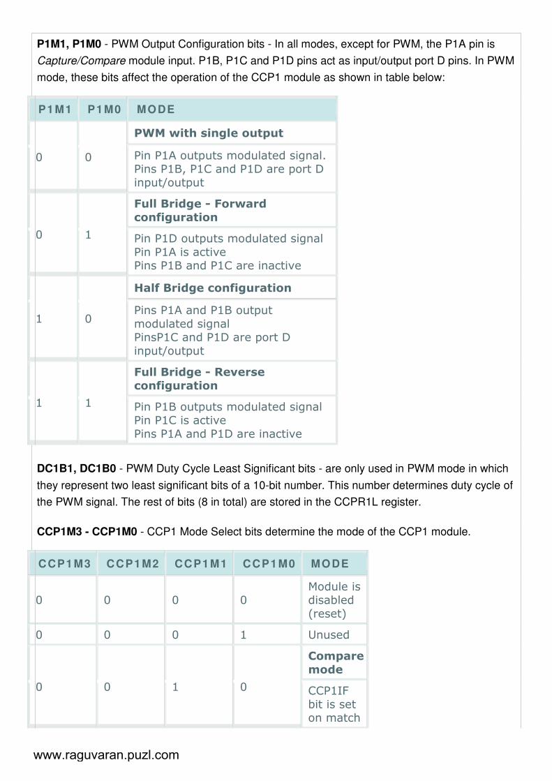
P1M1, P1M0 - PWM Output Configuration bits - In all modes, except for PWM, the P1A pin is
Capture/Compare module input. P1B, P1C and P1D pins act as input/output port D pins. In PWM
mode, these bits affect the operation of the CCP1 module as shown in table below:
P1M1 P1M0 MODE
0 0
PWM with single output
Pin P1A outputs modulated signal. Pins P1B, P1C and P1D are port D
input/output
0 1
Full Bridge - Forward
configuration
Pin P1D outputs modulated signal
Pin P1A is active Pins P1B and P1C are inactive
1 0
Half Bridge configuration
Pins P1A and P1B output
modulated signal PinsP1C and P1D are port D
input/output
1 1
Full Bridge - Reverse
configuration
Pin P1B outputs modulated signal Pin P1C is active
Pins P1A and P1D are inactive
DC1B1, DC1B0 - PWM Duty Cycle Least Significant bits - are only used in PWM mode in which
they represent two least significant bits of a 10-bit number. This number determines duty cycle of
the PWM signal. The rest of bits (8 in total) are stored in the CCPR1L register.
CCP1M3 - CCP1M0 - CCP1 Mode Select bits determine the mode of the CCP1 module.
CCP1M3 CCP1M2 CCP1M1 CCP1M0 MODE
0 0 0 0 Module is disabled
(reset)
0 0 0 1 Unused
0 0 1 0
Compare
mode
CCP1IF
bit is set on match
www.raguvaran.puzl.com
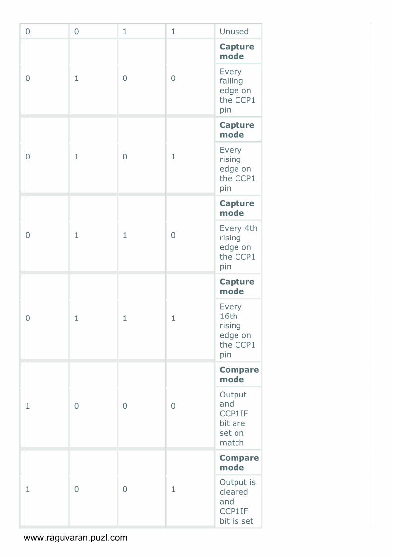
0 0 1 1 Unused
0 1 0 0
Capture mode
Every falling
edge on the CCP1
pin
0 1 0 1
Capture
mode
Every rising
edge on the CCP1
pin
0 1 1 0
Capture
mode
Every 4th
rising edge on
the CCP1 pin
0 1 1 1
Capture
mode
Every
16th rising
edge on the CCP1
pin
1 0 0 0
Compare
mode
Output
and CCP1IF
bit are set on
match
1 0 0 1
Compare
mode
Output is cleared
and CCP1IF
bit is set
www.raguvaran.puzl.com
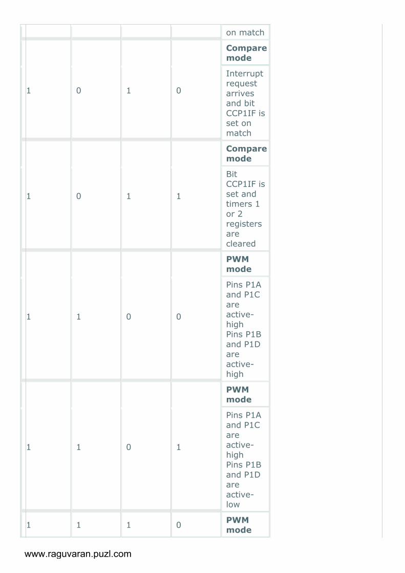
on match
1 0 1 0
Compare mode
Interrupt request
arrives and bit
CCP1IF is set on
match
1 0 1 1
Compare
mode
Bit CCP1IF is
set and timers 1
or 2
registers are
cleared
1 1 0 0
PWM mode
Pins P1A and P1C
are active-
high Pins P1B
and P1D are
active-
high
1 1 0 1
PWM mode
Pins P1A and P1C
are active-
high Pins P1B
and P1D are
active-low
1 1 1 0 PWM mode
www.raguvaran.puzl.com
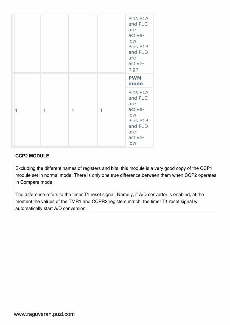
Pins P1A and P1C
are active-
low Pins P1B
and P1D are
active-high
1 1 1 1
PWM mode
Pins P1A
and P1C are
active-
low Pins P1B
and P1D are
active-low
CCP2 MODULE
Excluding the different names of registers and bits, this module is a very good copy of the CCP1
module set in normal mode. There is only one true difference between them when CCP2 operates
in Compare mode.
The difference refers to the timer T1 reset signal. Namely, if A/D converter is enabled, at the
moment the values of the TMR1 and CCPR2 registers match, the timer T1 reset signal will
automatically start A/D conversion.
www.raguvaran.puzl.com
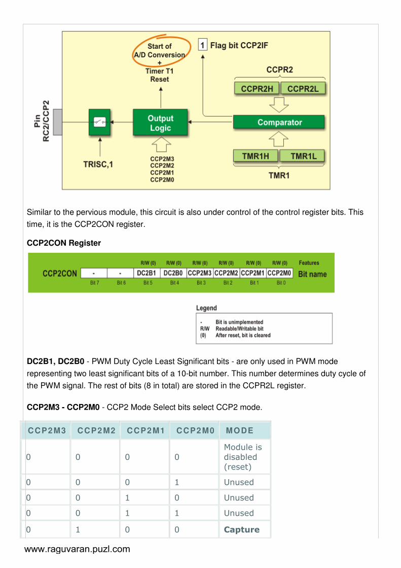
Similar to the pervious module, this circuit is also under control of the control register bits. This
time, it is the CCP2CON register.
CCP2CON Register
DC2B1, DC2B0 - PWM Duty Cycle Least Significant bits - are only used in PWM mode
representing two least significant bits of a 10-bit number. This number determines duty cycle of
the PWM signal. The rest of bits (8 in total) are stored in the CCPR2L register.
CCP2M3 - CCP2M0 - CCP2 Mode Select bits select CCP2 mode.
CCP2M3 CCP2M2 CCP2M1 CCP2M0 MODE
0 0 0 0
Module is
disabled (reset)
0 0 0 1 Unused
0 0 1 0 Unused
0 0 1 1 Unused
0 1 0 0 Capture
www.raguvaran.puzl.com
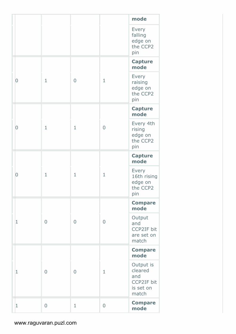
mode
Every falling
edge on the CCP2
pin
0 1 0 1
Capture
mode
Every
raising edge on
the CCP2 pin
0 1 1 0
Capture
mode
Every 4th
rising edge on
the CCP2 pin
0 1 1 1
Capture mode
Every 16th rising
edge on the CCP2
pin
1 0 0 0
Compare mode
Output and
CCP2IF bit are set on
match
1 0 0 1
Compare
mode
Output is
cleared and
CCP2IF bit is set on
match
1 0 1 0 Compare mode
www.raguvaran.puzl.com
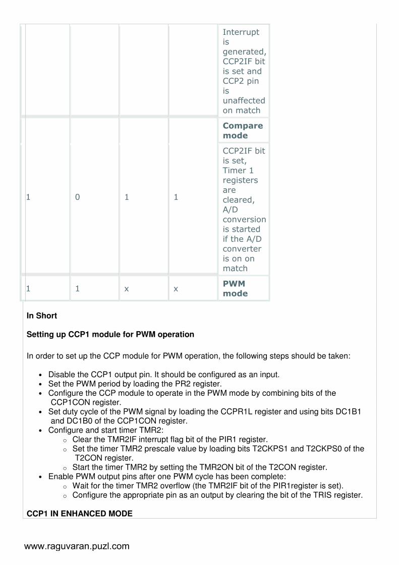
Interrupt is
generated, CCP2IF bit
is set and CCP2 pin
is unaffected
on match
1 0 1 1
Compare
mode
CCP2IF bit is set,
Timer 1 registers
are
cleared, A/D
conversion is started
if the A/D converter
is on on match
1 1 x x PWM mode
In Short
Setting up CCP1 module for PWM operation
In order to set up the CCP module for PWM operation, the following steps should be taken:
• Disable the CCP1 output pin. It should be configured as an input. • Set the PWM period by loading the PR2 register. • Configure the CCP module to operate in the PWM mode by combining bits of the
CCP1CON register. • Set duty cycle of the PWM signal by loading the CCPR1L register and using bits DC1B1
and DC1B0 of the CCP1CON register. • Configure and start timer TMR2:
o Clear the TMR2IF interrupt flag bit of the PIR1 register. o Set the timer TMR2 prescale value by loading bits T2CKPS1 and T2CKPS0 of the
T2CON register. o Start the timer TMR2 by setting the TMR2ON bit of the T2CON register.
• Enable PWM output pins after one PWM cycle has been complete: o Wait for the timer TMR2 overflow (the TMR2IF bit of the PIR1register is set). o Configure the appropriate pin as an output by clearing the bit of the TRIS register.
CCP1 IN ENHANCED MODE
www.raguvaran.puzl.com
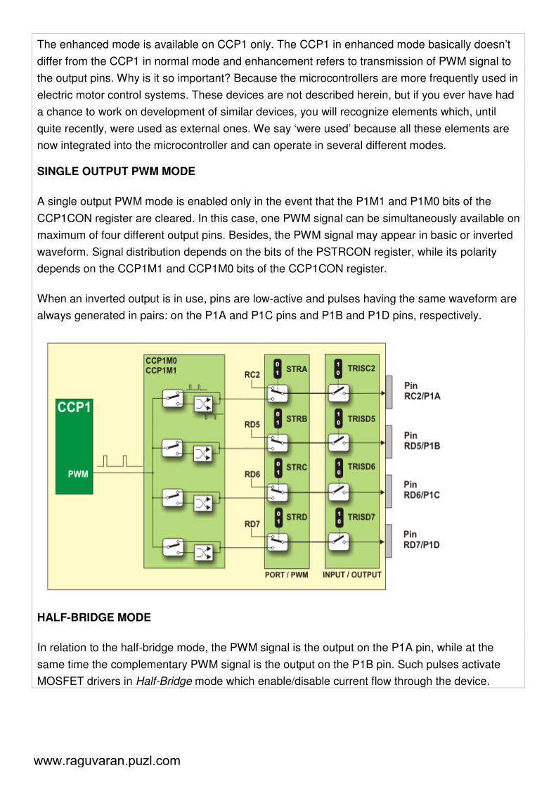
The enhanced mode is available on CCP1 only. The CCP1 in enhanced mode basically doesn’t
differ from the CCP1 in normal mode and enhancement refers to transmission of PWM signal to
the output pins. Why is it so important? Because the microcontrollers are more frequently used in
electric motor control systems. These devices are not described herein, but if you ever have had
a chance to work on development of similar devices, you will recognize elements which, until
quite recently, were used as external ones. We say ‘were used’ because all these elements are
now integrated into the microcontroller and can operate in several different modes.
SINGLE OUTPUT PWM MODE
A single output PWM mode is enabled only in the event that the P1M1 and P1M0 bits of the
CCP1CON register are cleared. In this case, one PWM signal can be simultaneously available on
maximum of four different output pins. Besides, the PWM signal may appear in basic or inverted
waveform. Signal distribution depends on the bits of the PSTRCON register, while its polarity
depends on the CCP1M1 and CCP1M0 bits of the CCP1CON register.
When an inverted output is in use, pins are low-active and pulses having the same waveform are
always generated in pairs: on the P1A and P1C pins and P1B and P1D pins, respectively.
HALF-BRIDGE MODE
In relation to the half-bridge mode, the PWM signal is the output on the P1A pin, while at the
same time the complementary PWM signal is the output on the P1B pin. Such pulses activate
MOSFET drivers in Half-Bridge mode which enable/disable current flow through the device.
www.raguvaran.puzl.com
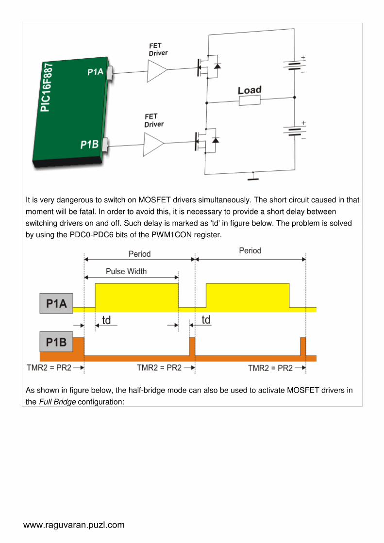
It is very dangerous to switch on MOSFET drivers simultaneously. The short circuit caused in that
moment will be fatal. In order to avoid this, it is necessary to provide a short delay between
switching drivers on and off. Such delay is marked as 'td' in figure below. The problem is solved
by using the PDC0-PDC6 bits of the PWM1CON register.
As shown in figure below, the half-bridge mode can also be used to activate MOSFET drivers in
the Full Bridge configuration:
www.raguvaran.puzl.com
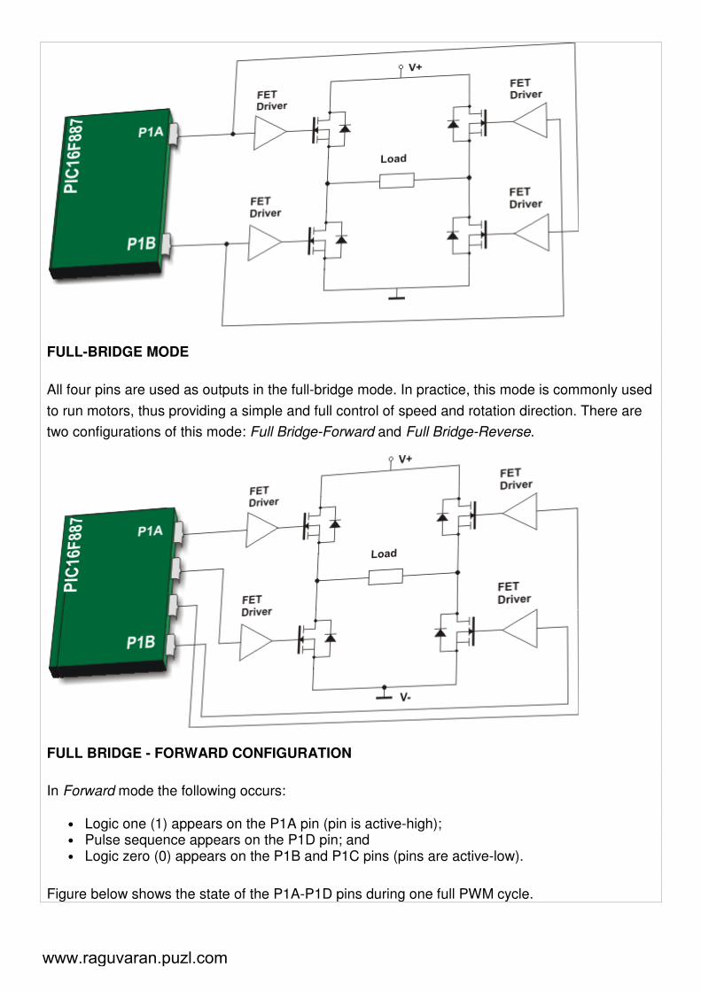
FULL-BRIDGE MODE
All four pins are used as outputs in the full-bridge mode. In practice, this mode is commonly used
to run motors, thus providing a simple and full control of speed and rotation direction. There are
two configurations of this mode: Full Bridge-Forward and Full Bridge-Reverse.
FULL BRIDGE - FORWARD CONFIGURATION
In Forward mode the following occurs:
• Logic one (1) appears on the P1A pin (pin is active-high); • Pulse sequence appears on the P1D pin; and • Logic zero (0) appears on the P1B and P1C pins (pins are active-low).
Figure below shows the state of the P1A-P1D pins during one full PWM cycle.
www.raguvaran.puzl.com
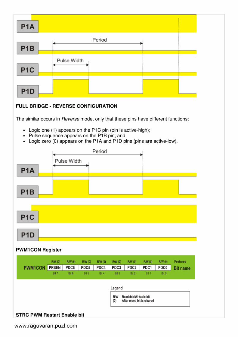
FULL BRIDGE - REVERSE CONFIGURATION
The similar occurs in Reverse mode, only that these pins have different functions:
• Logic one (1) appears on the P1C pin (pin is active-high); • Pulse sequence appears on the P1B pin; and • Logic zero (0) appears on the P1A and P1D pins (pins are active-low).
PWM1CON Register
STRC PWM Restart Enable bit
www.raguvaran.puzl.com
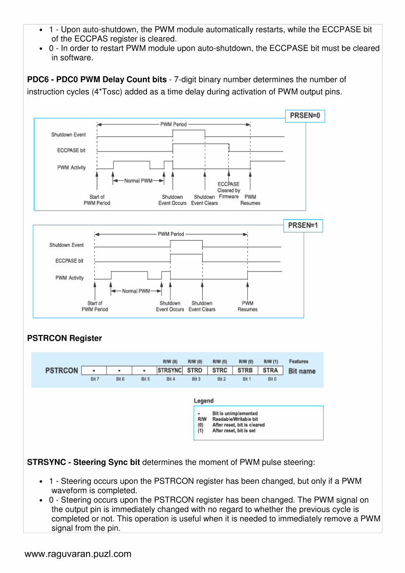
• 1 - Upon auto-shutdown, the PWM module automatically restarts, while the ECCPASE bit of the ECCPAS register is cleared.
• 0 - In order to restart PWM module upon auto-shutdown, the ECCPASE bit must be cleared in software.
PDC6 - PDC0 PWM Delay Count bits - 7-digit binary number determines the number of
instruction cycles (4*Tosc) added as a time delay during activation of PWM output pins.
PSTRCON Register
STRSYNC - Steering Sync bit determines the moment of PWM pulse steering:
• 1 - Steering occurs upon the PSTRCON register has been changed, but only if a PWM waveform is completed.
• 0 - Steering occurs upon the PSTRCON register has been changed. The PWM signal on the output pin is immediately changed with no regard to whether the previous cycle is completed or not. This operation is useful when it is needed to immediately remove a PWM signal from the pin.
www.raguvaran.puzl.com
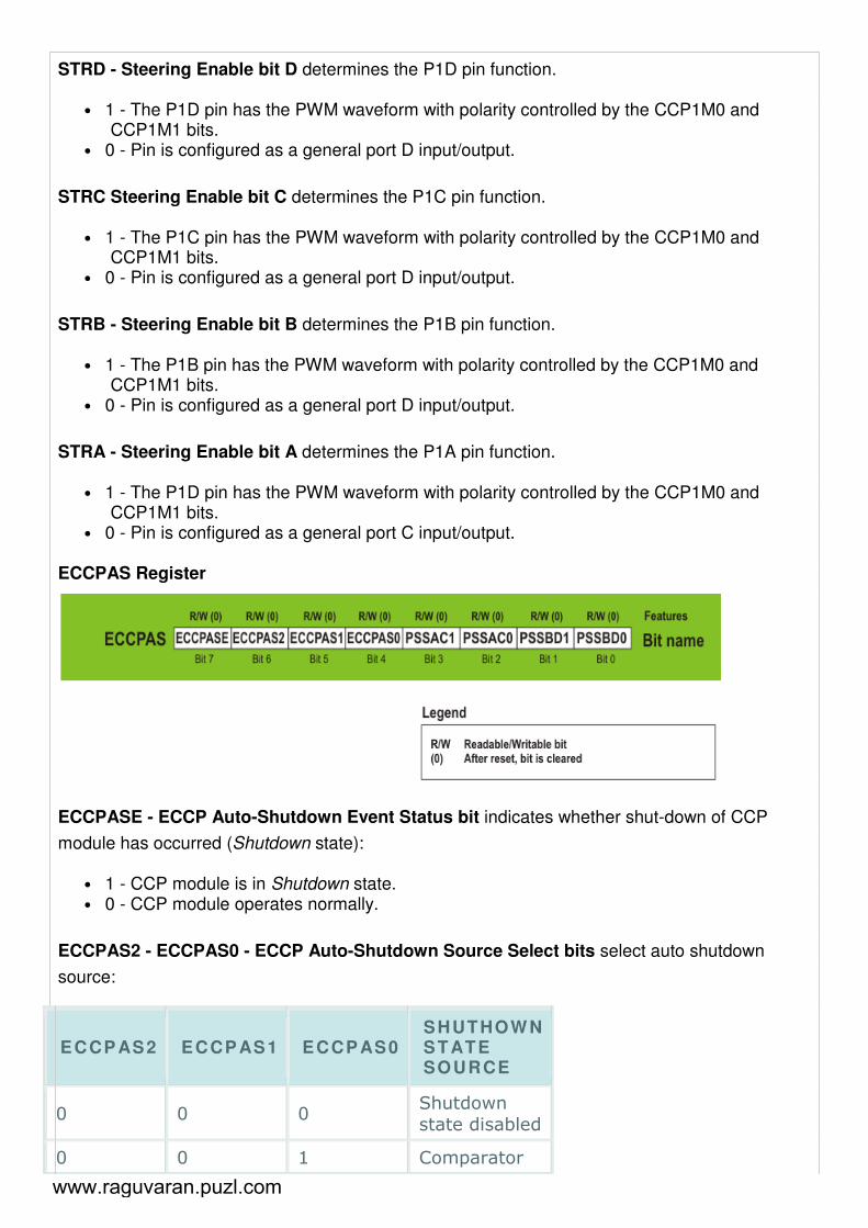
STRD - Steering Enable bit D determines the P1D pin function.
• 1 - The P1D pin has the PWM waveform with polarity controlled by the CCP1M0 and CCP1M1 bits.
• 0 - Pin is configured as a general port D input/output.
STRC Steering Enable bit C determines the P1C pin function.
• 1 - The P1C pin has the PWM waveform with polarity controlled by the CCP1M0 and CCP1M1 bits.
• 0 - Pin is configured as a general port D input/output.
STRB - Steering Enable bit B determines the P1B pin function.
• 1 - The P1B pin has the PWM waveform with polarity controlled by the CCP1M0 and CCP1M1 bits.
• 0 - Pin is configured as a general port D input/output.
STRA - Steering Enable bit A determines the P1A pin function.
• 1 - The P1D pin has the PWM waveform with polarity controlled by the CCP1M0 and CCP1M1 bits.
• 0 - Pin is configured as a general port C input/output.
ECCPAS Register
ECCPASE - ECCP Auto-Shutdown Event Status bit indicates whether shut-down of CCP
module has occurred (Shutdown state):
• 1 - CCP module is in Shutdown state. • 0 - CCP module operates normally.
ECCPAS2 - ECCPAS0 - ECCP Auto-Shutdown Source Select bits select auto shutdown
source:
ECCP AS2 ECCP AS1 ECCP AS0 SHUTHOWN ST ATE SOURCE
0 0 0 Shutdown
state disabled
0 0 1 Comparator
www.raguvaran.puzl.com
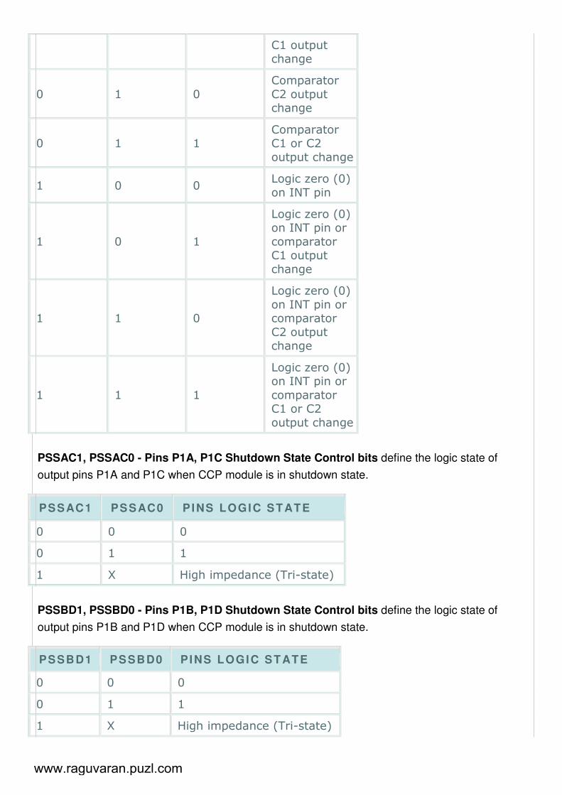
C1 output change
0 1 0
Comparator
C2 output change
0 1 1 Comparator C1 or C2
output change
1 0 0 Logic zero (0)
on INT pin
1 0 1
Logic zero (0) on INT pin or
comparator C1 output
change
1 1 0
Logic zero (0)
on INT pin or comparator
C2 output change
1 1 1
Logic zero (0) on INT pin or
comparator C1 or C2
output change
PSSAC1, PSSAC0 - Pins P1A, P1C Shutdown State Control bits define the logic state of
output pins P1A and P1C when CCP module is in shutdown state.
PSSAC1 PSSAC0 PINS LOGIC ST ATE
0 0 0
0 1 1
1 X High impedance (Tri-state)
PSSBD1, PSSBD0 - Pins P1B, P1D Shutdown State Control bits define the logic state of
output pins P1B and P1D when CCP module is in shutdown state.
PSSBD1 PSSBD0 PINS LOGIC ST ATE
0 0 0
0 1 1
1 X High impedance (Tri-state)
www.raguvaran.puzl.com
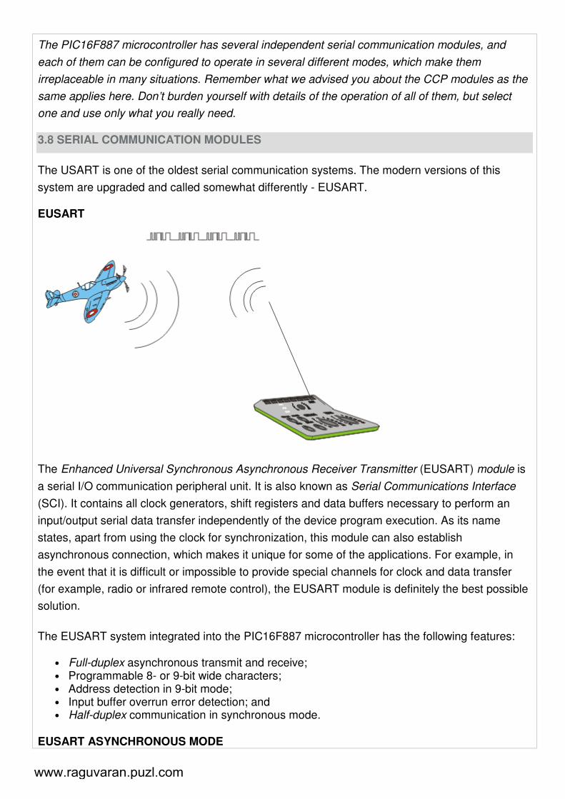
The PIC16F887 microcontroller has several independent serial communication modules, and
each of them can be configured to operate in several different modes, which make them
irreplaceable in many situations. Remember what we advised you about the CCP modules as the
same applies here. Don’t burden yourself with details of the operation of all of them, but select
one and use only what you really need.
3.8 SERIAL COMMUNICATION MODULES
The USART is one of the oldest serial communication systems. The modern versions of this
system are upgraded and called somewhat differently - EUSART.
EUSART
The Enhanced Universal Synchronous Asynchronous Receiver Transmitter (EUSART) module is
a serial I/O communication peripheral unit. It is also known as Serial Communications Interface
(SCI). It contains all clock generators, shift registers and data buffers necessary to perform an
input/output serial data transfer independently of the device program execution. As its name
states, apart from using the clock for synchronization, this module can also establish
asynchronous connection, which makes it unique for some of the applications. For example, in
the event that it is difficult or impossible to provide special channels for clock and data transfer
(for example, radio or infrared remote control), the EUSART module is definitely the best possible
solution.
The EUSART system integrated into the PIC16F887 microcontroller has the following features:
• Full-duplex asynchronous transmit and receive; • Programmable 8- or 9-bit wide characters; • Address detection in 9-bit mode; • Input buffer overrun error detection; and • Half-duplex communication in synchronous mode.
EUSART ASYNCHRONOUS MODE
www.raguvaran.puzl.com
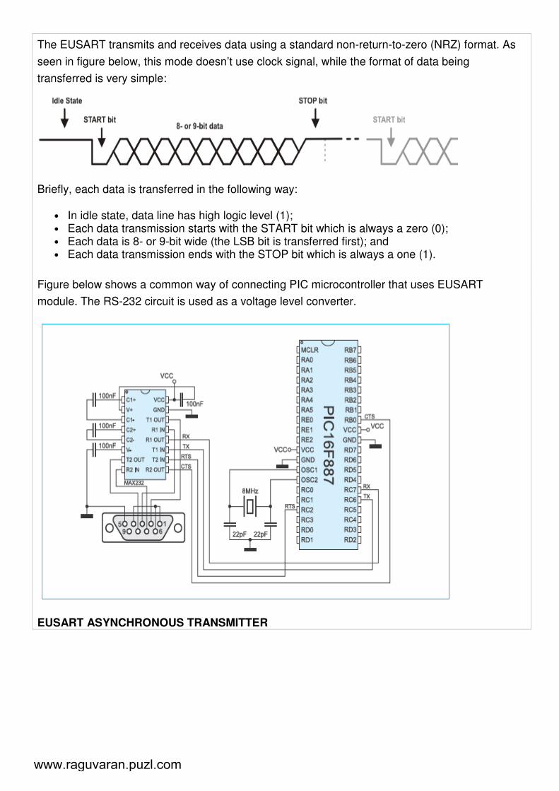
The EUSART transmits and receives data using a standard non-return-to-zero (NRZ) format. As
seen in figure below, this mode doesn’t use clock signal, while the format of data being
transferred is very simple:
Briefly, each data is transferred in the following way:
• In idle state, data line has high logic level (1); • Each data transmission starts with the START bit which is always a zero (0); • Each data is 8- or 9-bit wide (the LSB bit is transferred first); and • Each data transmission ends with the STOP bit which is always a one (1).
Figure below shows a common way of connecting PIC microcontroller that uses EUSART
module. The RS-232 circuit is used as a voltage level converter.
EUSART ASYNCHRONOUS TRANSMITTER
www.raguvaran.puzl.com
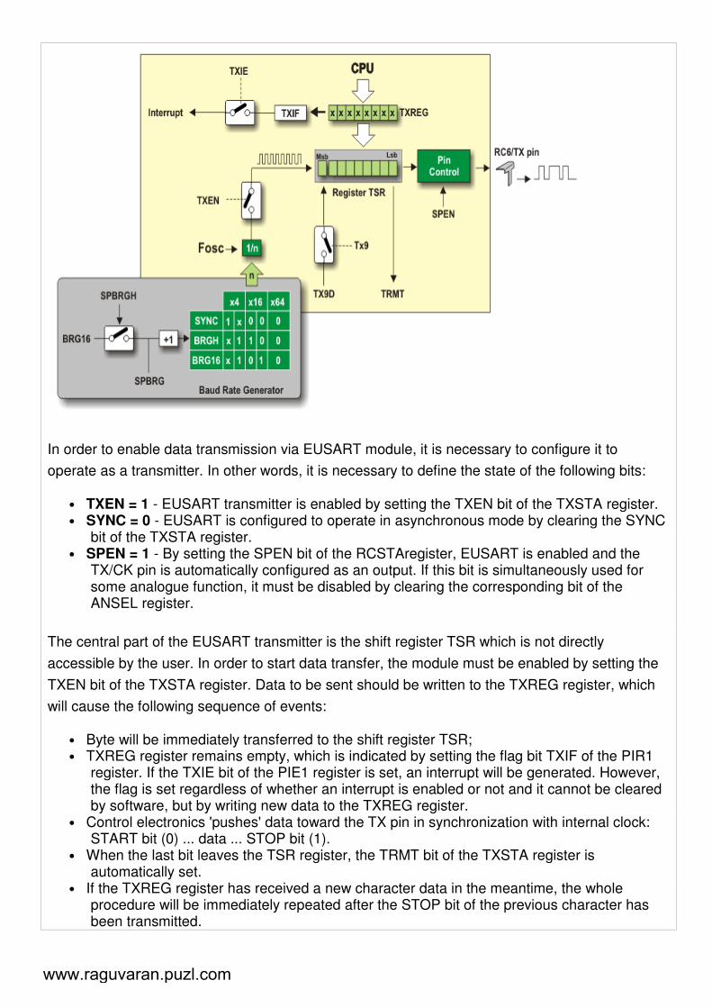
In order to enable data transmission via EUSART module, it is necessary to configure it to
operate as a transmitter. In other words, it is necessary to define the state of the following bits:
• TXEN = 1 - EUSART transmitter is enabled by setting the TXEN bit of the TXSTA register. • SYNC = 0 - EUSART is configured to operate in asynchronous mode by clearing the SYNC
bit of the TXSTA register. • SPEN = 1 - By setting the SPEN bit of the RCSTAregister, EUSART is enabled and the
TX/CK pin is automatically configured as an output. If this bit is simultaneously used for some analogue function, it must be disabled by clearing the corresponding bit of the ANSEL register.
The central part of the EUSART transmitter is the shift register TSR which is not directly
accessible by the user. In order to start data transfer, the module must be enabled by setting the
TXEN bit of the TXSTA register. Data to be sent should be written to the TXREG register, which
will cause the following sequence of events:
• Byte will be immediately transferred to the shift register TSR; • TXREG register remains empty, which is indicated by setting the flag bit TXIF of the PIR1
register. If the TXIE bit of the PIE1 register is set, an interrupt will be generated. However, the flag is set regardless of whether an interrupt is enabled or not and it cannot be cleared by software, but by writing new data to the TXREG register.
• Control electronics 'pushes' data toward the TX pin in synchronization with internal clock: START bit (0) ... data ... STOP bit (1).
• When the last bit leaves the TSR register, the TRMT bit of the TXSTA register is automatically set.
• If the TXREG register has received a new character data in the meantime, the whole procedure will be immediately repeated after the STOP bit of the previous character has been transmitted.
www.raguvaran.puzl.com
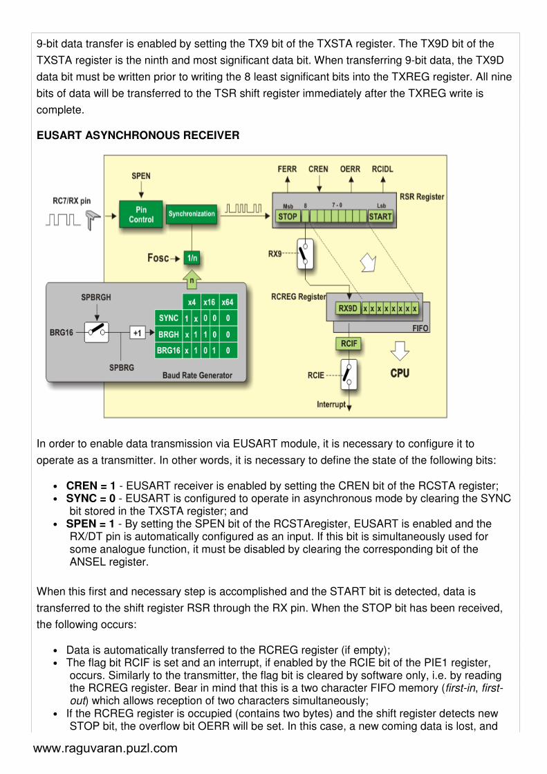
9-bit data transfer is enabled by setting the TX9 bit of the TXSTA register. The TX9D bit of the
TXSTA register is the ninth and most significant data bit. When transferring 9-bit data, the TX9D
data bit must be written prior to writing the 8 least significant bits into the TXREG register. All nine
bits of data will be transferred to the TSR shift register immediately after the TXREG write is
complete.
EUSART ASYNCHRONOUS RECEIVER
In order to enable data transmission via EUSART module, it is necessary to configure it to
operate as a transmitter. In other words, it is necessary to define the state of the following bits:
• CREN = 1 - EUSART receiver is enabled by setting the CREN bit of the RCSTA register; • SYNC = 0 - EUSART is configured to operate in asynchronous mode by clearing the SYNC
bit stored in the TXSTA register; and • SPEN = 1 - By setting the SPEN bit of the RCSTAregister, EUSART is enabled and the
RX/DT pin is automatically configured as an input. If this bit is simultaneously used for some analogue function, it must be disabled by clearing the corresponding bit of the ANSEL register.
When this first and necessary step is accomplished and the START bit is detected, data is
transferred to the shift register RSR through the RX pin. When the STOP bit has been received,
the following occurs:
• Data is automatically transferred to the RCREG register (if empty); • The flag bit RCIF is set and an interrupt, if enabled by the RCIE bit of the PIE1 register,
occurs. Similarly to the transmitter, the flag bit is cleared by software only, i.e. by reading the RCREG register. Bear in mind that this is a two character FIFO memory (first-in, first-out) which allows reception of two characters simultaneously;
• If the RCREG register is occupied (contains two bytes) and the shift register detects new STOP bit, the overflow bit OERR will be set. In this case, a new coming data is lost, and
www.raguvaran.puzl.com

the OEER bit must be cleared by software. It is done by clearing and resetting the CREN bit; Note: it is not possible to receive new data as far as the OERR bit is set.
• If the STOP bit is a zero (0), the FERR bit of the RCSTA register detecting receive error will be set; and
• To enable 9-bit data reception, it is necessary to set the RX9 bit of the RCSTA register.
RECEIVE ERROR DETECTION
There are two types of errors which the microcontroller can automatically detect. The first one is
called Framing error and occurs when the receiver does not detect the STOP bit at the expected
time. Such an error is indicated by the FERR bit of the RCSTA register. If this bit is set, the last
received data may be incorrect. Here are several things important to know:
• A Framing error does not generate an interrupt by itself; • If this bit is set, the last received data has an error; • A framing error (bit set) does not prevent reception of new data; • The FERR bit is cleared by reading received data, which means that check must be done
prior to reading data; and • The FERR bit cannot be cleared by software. If needed, it can be cleared by clearing the
SPEN bit of the RCSTA register. It will simultaneously cause the whole EUSART system to be reset.
Another type of error is called Overrun Error. As previously mentioned, the FIFO memory can
receive two characters only. An overrun error will be generated if the third character is received.
Simply put, there is no space for another one byte and an error is unavoidable. When this
happens the OERR bit of the RCSTA register is set. The consequences are the following:
• Data already stored in the FIFO registers (two bytes) can be normally read; • No additional data will be received until the OERR bit is cleared; and • This bit is not directly accessed. To clear it, it is necessary to clear the CREN bit of the
RCSTAregister or reset the whole EUSART system by clearing the SPEN bit of the RCSTA register.
9-BIT DATA RECEIVE
Apart from receiving standard 8-bit data, the EUSART system supports 9-bit data reception. On
the transmit side, the ninth bit is ‘attached’ to the original byte directly before the STOP bit. On the
receive side, when the RX9 bit of the RCSTA register is set, the ninth data bit will be automatically
written to the RX9D bit of the same register. After receiving this byte, it is necessary to take care
of how to read its bits- the RX9D data bit must be read prior to reading 8 least significant bits of
the RCREG register. Otherwise, the ninth data bit will be cleared.
www.raguvaran.puzl.com
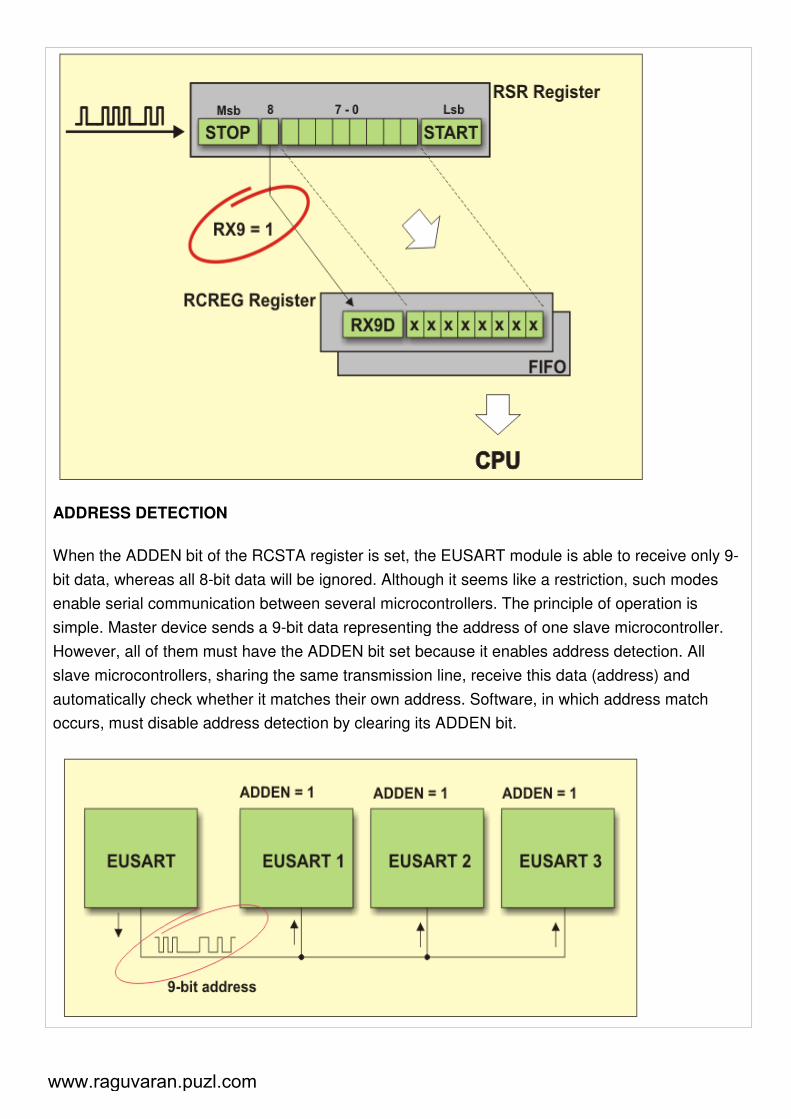
ADDRESS DETECTION
When the ADDEN bit of the RCSTA register is set, the EUSART module is able to receive only 9-
bit data, whereas all 8-bit data will be ignored. Although it seems like a restriction, such modes
enable serial communication between several microcontrollers. The principle of operation is
simple. Master device sends a 9-bit data representing the address of one slave microcontroller.
However, all of them must have the ADDEN bit set because it enables address detection. All
slave microcontrollers, sharing the same transmission line, receive this data (address) and
automatically check whether it matches their own address. Software, in which address match
occurs, must disable address detection by clearing its ADDEN bit.
www.raguvaran.puzl.com
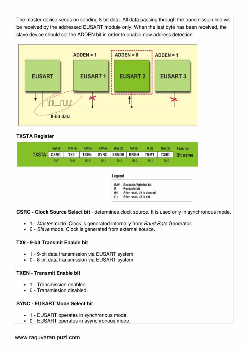
The master device keeps on sending 8-bit data. All data passing through the transmission line will
be received by the addressed EUSART module only. When the last byte has been received, the
slave device should set the ADDEN bit in order to enable new address detection.
TXSTA Register
CSRC - Clock Source Select bit - determines clock source. It is used only in synchronous mode.
• 1 - Master mode. Clock is generated internally from Baud Rate Generator. • 0 - Slave mode. Clock is generated from external source.
TX9 - 9-bit Transmit Enable bit
• 1 - 9-bit data transmission via EUSART system. • 0 - 8-bit data transmission via EUSART system.
TXEN - Transmit Enable bit
• 1 - Transmission enabled. • 0 - Transmission disabled.
SYNC - EUSART Mode Select bit
• 1 - EUSART operates in synchronous mode. • 0 - EUSART operates in asynchronous mode.
www.raguvaran.puzl.com
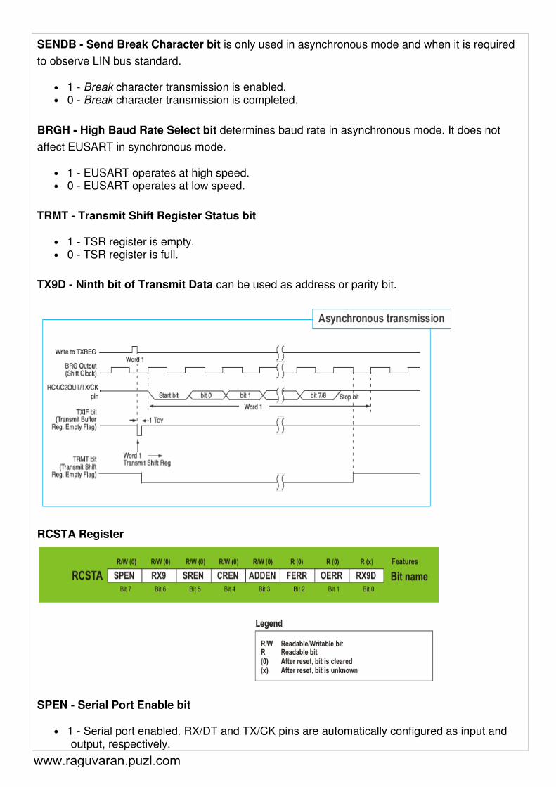
SENDB - Send Break Character bit is only used in asynchronous mode and when it is required
to observe LIN bus standard.
• 1 - Break character transmission is enabled. • 0 - Break character transmission is completed.
BRGH - High Baud Rate Select bit determines baud rate in asynchronous mode. It does not
affect EUSART in synchronous mode.
• 1 - EUSART operates at high speed. • 0 - EUSART operates at low speed.
TRMT - Transmit Shift Register Status bit
• 1 - TSR register is empty. • 0 - TSR register is full.
TX9D - Ninth bit of Transmit Data can be used as address or parity bit.
RCSTA Register
SPEN - Serial Port Enable bit
• 1 - Serial port enabled. RX/DT and TX/CK pins are automatically configured as input and output, respectively.
www.raguvaran.puzl.com
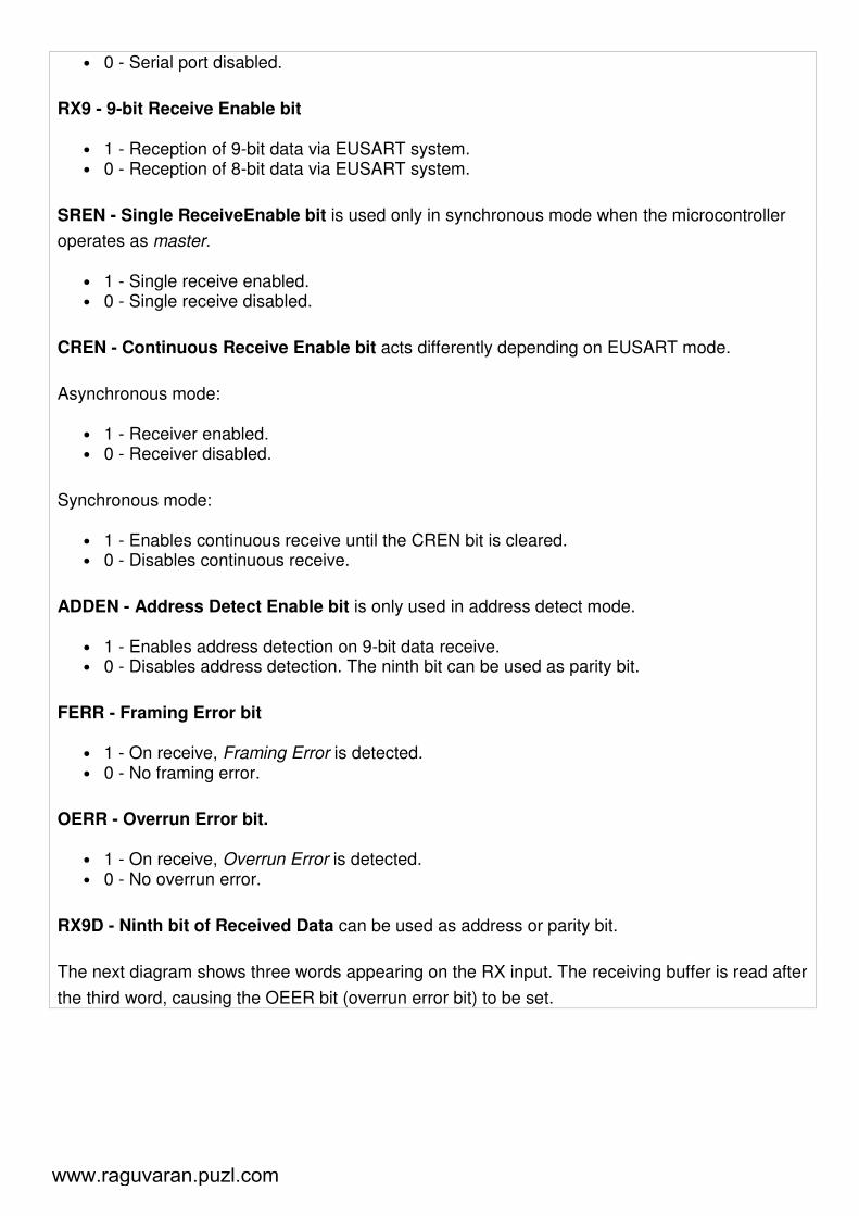
• 0 - Serial port disabled.
RX9 - 9-bit Receive Enable bit
• 1 - Reception of 9-bit data via EUSART system. • 0 - Reception of 8-bit data via EUSART system.
SREN - Single ReceiveEnable bit is used only in synchronous mode when the microcontroller
operates as master.
• 1 - Single receive enabled. • 0 - Single receive disabled.
CREN - Continuous Receive Enable bit acts differently depending on EUSART mode.
Asynchronous mode:
• 1 - Receiver enabled. • 0 - Receiver disabled.
Synchronous mode:
• 1 - Enables continuous receive until the CREN bit is cleared. • 0 - Disables continuous receive.
ADDEN - Address Detect Enable bit is only used in address detect mode.
• 1 - Enables address detection on 9-bit data receive. • 0 - Disables address detection. The ninth bit can be used as parity bit.
FERR - Framing Error bit
• 1 - On receive, Framing Error is detected. • 0 - No framing error.
OERR - Overrun Error bit.
• 1 - On receive, Overrun Error is detected. • 0 - No overrun error.
RX9D - Ninth bit of Received Data can be used as address or parity bit.
The next diagram shows three words appearing on the RX input. The receiving buffer is read after
the third word, causing the OEER bit (overrun error bit) to be set.
www.raguvaran.puzl.com
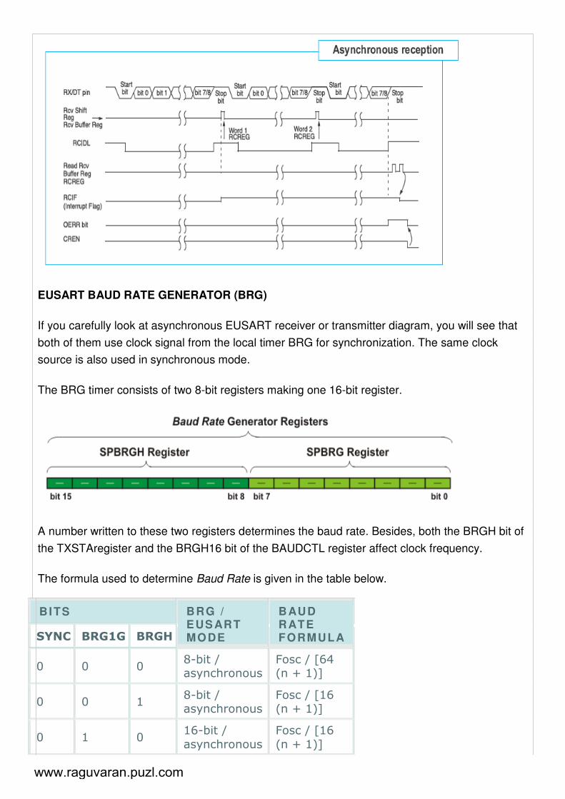
EUSART BAUD RATE GENERATOR (BRG)
If you carefully look at asynchronous EUSART receiver or transmitter diagram, you will see that
both of them use clock signal from the local timer BRG for synchronization. The same clock
source is also used in synchronous mode.
The BRG timer consists of two 8-bit registers making one 16-bit register.
A number written to these two registers determines the baud rate. Besides, both the BRGH bit of
the TXSTAregister and the BRGH16 bit of the BAUDCTL register affect clock frequency.
The formula used to determine Baud Rate is given in the table below.
BITS BRG / EUS ART MODE
BAUD RATE FORMULA SYNC BRG1G BRGH
0 0 0 8-bit / asynchronous
Fosc / [64 (n + 1)]
0 0 1 8-bit / asynchronous
Fosc / [16 (n + 1)]
0 1 0 16-bit /
asynchronous
Fosc / [16
(n + 1)]
www.raguvaran.puzl.com
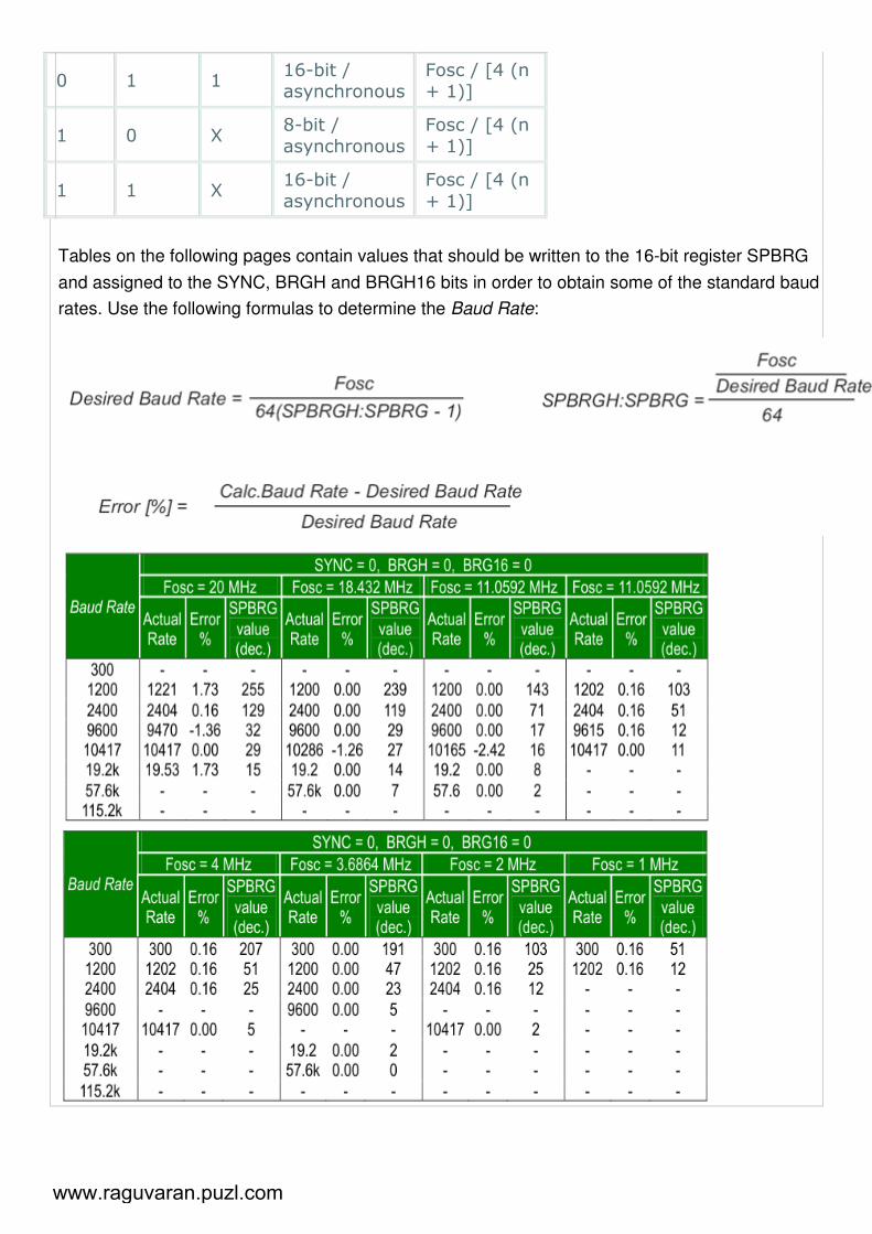
0 1 1 16-bit / asynchronous
Fosc / [4 (n + 1)]
1 0 X 8-bit /
asynchronous
Fosc / [4 (n
+ 1)]
1 1 X 16-bit /
asynchronous
Fosc / [4 (n
+ 1)]
Tables on the following pages contain values that should be written to the 16-bit register SPBRG
and assigned to the SYNC, BRGH and BRGH16 bits in order to obtain some of the standard baud
rates. Use the following formulas to determine the Baud Rate:
www.raguvaran.puzl.com
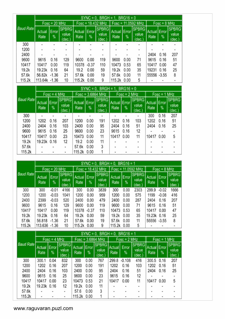
www.raguvaran.puzl.com
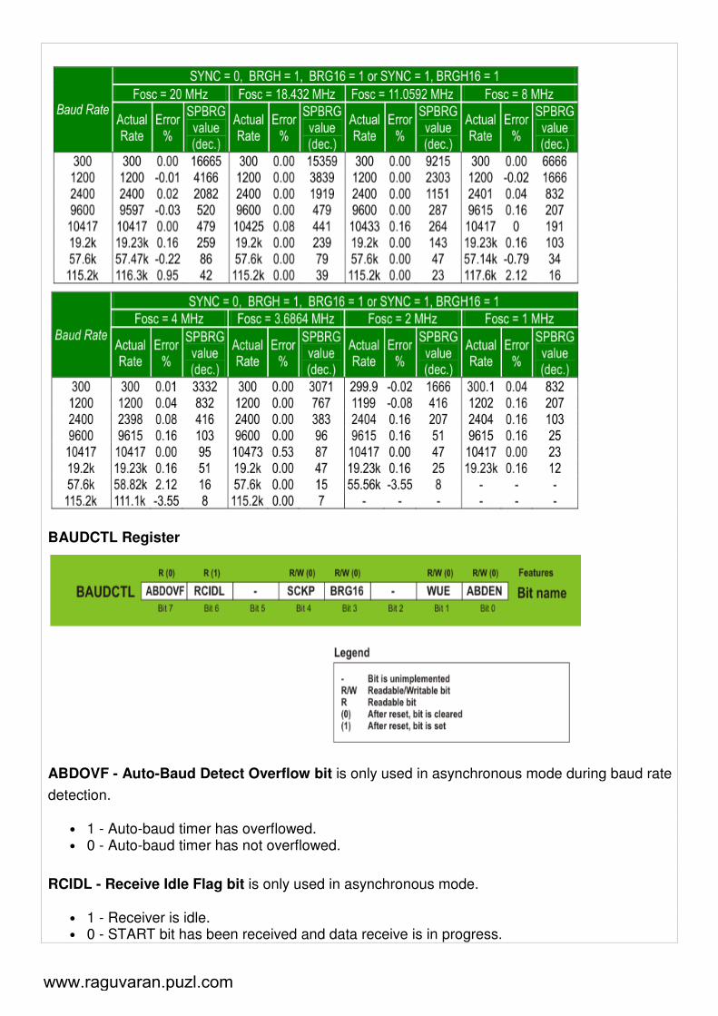
BAUDCTL Register
ABDOVF - Auto-Baud Detect Overflow bit is only used in asynchronous mode during baud rate
detection.
• 1 - Auto-baud timer has overflowed. • 0 - Auto-baud timer has not overflowed.
RCIDL - Receive Idle Flag bit is only used in asynchronous mode.
• 1 - Receiver is idle. • 0 - START bit has been received and data receive is in progress.
www.raguvaran.puzl.com
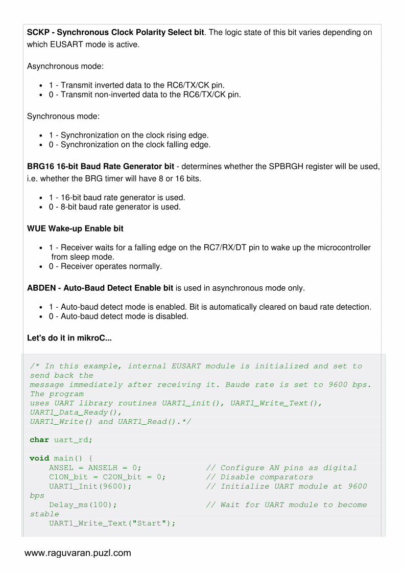
SCKP - Synchronous Clock Polarity Select bit. The logic state of this bit varies depending on
which EUSART mode is active.
Asynchronous mode:
• 1 - Transmit inverted data to the RC6/TX/CK pin. • 0 - Transmit non-inverted data to the RC6/TX/CK pin.
Synchronous mode:
• 1 - Synchronization on the clock rising edge. • 0 - Synchronization on the clock falling edge.
BRG16 16-bit Baud Rate Generator bit - determines whether the SPBRGH register will be used,
i.e. whether the BRG timer will have 8 or 16 bits.
• 1 - 16-bit baud rate generator is used. • 0 - 8-bit baud rate generator is used.
WUE Wake-up Enable bit
• 1 - Receiver waits for a falling edge on the RC7/RX/DT pin to wake up the microcontroller from sleep mode.
• 0 - Receiver operates normally.
ABDEN - Auto-Baud Detect Enable bit is used in asynchronous mode only.
• 1 - Auto-baud detect mode is enabled. Bit is automatically cleared on baud rate detection. • 0 - Auto-baud detect mode is disabled.
Let's do it in mikroC...
/* In this example, internal EUSART module is initialized and set to
send back the
message immediately after receiving it. Baude rate is set to 9600 bps.
The program
uses UART library routines UART1_init(), UART1_Write_Text(),
UART1_Data_Ready(),
UART1_Write() and UART1_Read().*/
char uart_rd;
void main()
ANSEL = ANSELH = 0; // Configure AN pins as digital
C1ON_bit = C2ON_bit = 0; // Disable comparators
UART1_Init(9600); // Initialize UART module at 9600
bps
Delay_ms(100); // Wait for UART module to become
stable
UART1_Write_Text("Start");
www.raguvaran.puzl.com
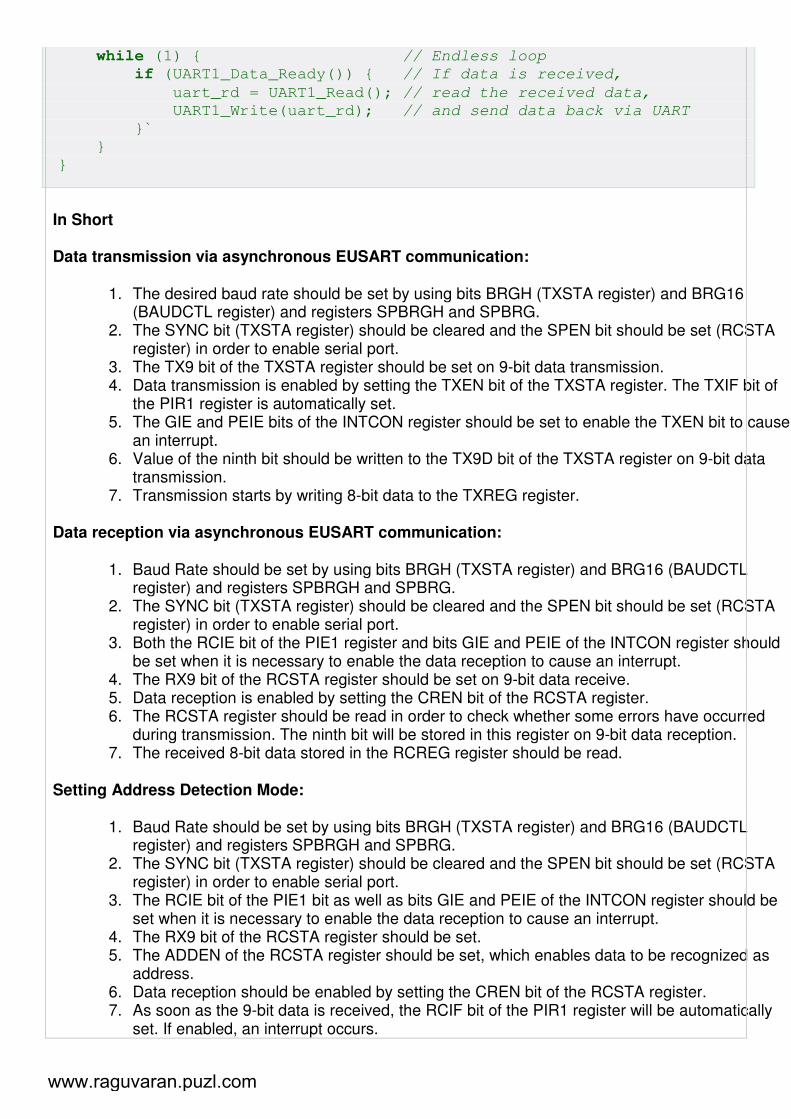
while (1) // Endless loop
if (UART1_Data_Ready()) // If data is received,
uart_rd = UART1_Read(); // read the received data,
UART1_Write(uart_rd); // and send data back via UART
`
In Short
Data transmission via asynchronous EUSART communication:
1. The desired baud rate should be set by using bits BRGH (TXSTA register) and BRG16 (BAUDCTL register) and registers SPBRGH and SPBRG.
2. The SYNC bit (TXSTA register) should be cleared and the SPEN bit should be set (RCSTA register) in order to enable serial port.
3. The TX9 bit of the TXSTA register should be set on 9-bit data transmission. 4. Data transmission is enabled by setting the TXEN bit of the TXSTA register. The TXIF bit of
the PIR1 register is automatically set. 5. The GIE and PEIE bits of the INTCON register should be set to enable the TXEN bit to cause
an interrupt. 6. Value of the ninth bit should be written to the TX9D bit of the TXSTA register on 9-bit data
transmission. 7. Transmission starts by writing 8-bit data to the TXREG register.
Data reception via asynchronous EUSART communication:
1. Baud Rate should be set by using bits BRGH (TXSTA register) and BRG16 (BAUDCTL register) and registers SPBRGH and SPBRG.
2. The SYNC bit (TXSTA register) should be cleared and the SPEN bit should be set (RCSTA register) in order to enable serial port.
3. Both the RCIE bit of the PIE1 register and bits GIE and PEIE of the INTCON register should be set when it is necessary to enable the data reception to cause an interrupt.
4. The RX9 bit of the RCSTA register should be set on 9-bit data receive. 5. Data reception is enabled by setting the CREN bit of the RCSTA register. 6. The RCSTA register should be read in order to check whether some errors have occurred
during transmission. The ninth bit will be stored in this register on 9-bit data reception. 7. The received 8-bit data stored in the RCREG register should be read.
Setting Address Detection Mode:
1. Baud Rate should be set by using bits BRGH (TXSTA register) and BRG16 (BAUDCTL register) and registers SPBRGH and SPBRG.
2. The SYNC bit (TXSTA register) should be cleared and the SPEN bit should be set (RCSTA register) in order to enable serial port.
3. The RCIE bit of the PIE1 bit as well as bits GIE and PEIE of the INTCON register should be set when it is necessary to enable the data reception to cause an interrupt.
4. The RX9 bit of the RCSTA register should be set. 5. The ADDEN of the RCSTA register should be set, which enables data to be recognized as
address. 6. Data reception should be enabled by setting the CREN bit of the RCSTA register. 7. As soon as the 9-bit data is received, the RCIF bit of the PIR1 register will be automatically
set. If enabled, an interrupt occurs.
www.raguvaran.puzl.com
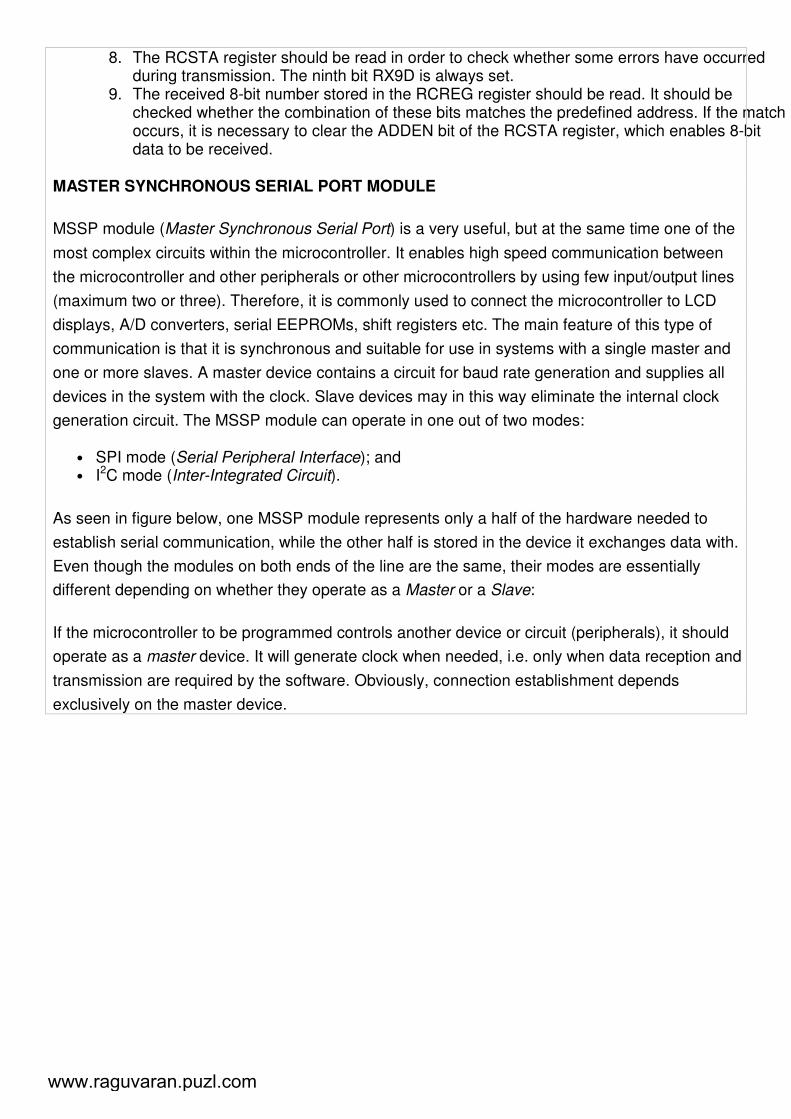
8. The RCSTA register should be read in order to check whether some errors have occurred during transmission. The ninth bit RX9D is always set.
9. The received 8-bit number stored in the RCREG register should be read. It should be checked whether the combination of these bits matches the predefined address. If the match occurs, it is necessary to clear the ADDEN bit of the RCSTA register, which enables 8-bit data to be received.
MASTER SYNCHRONOUS SERIAL PORT MODULE
MSSP module (Master Synchronous Serial Port) is a very useful, but at the same time one of the
most complex circuits within the microcontroller. It enables high speed communication between
the microcontroller and other peripherals or other microcontrollers by using few input/output lines
(maximum two or three). Therefore, it is commonly used to connect the microcontroller to LCD
displays, A/D converters, serial EEPROMs, shift registers etc. The main feature of this type of
communication is that it is synchronous and suitable for use in systems with a single master and
one or more slaves. A master device contains a circuit for baud rate generation and supplies all
devices in the system with the clock. Slave devices may in this way eliminate the internal clock
generation circuit. The MSSP module can operate in one out of two modes:
• SPI mode (Serial Peripheral Interface); and • I2C mode (Inter-Integrated Circuit).
As seen in figure below, one MSSP module represents only a half of the hardware needed to
establish serial communication, while the other half is stored in the device it exchanges data with.
Even though the modules on both ends of the line are the same, their modes are essentially
different depending on whether they operate as a Master or a Slave:
If the microcontroller to be programmed controls another device or circuit (peripherals), it should
operate as a master device. It will generate clock when needed, i.e. only when data reception and
transmission are required by the software. Obviously, connection establishment depends
exclusively on the master device.
www.raguvaran.puzl.com
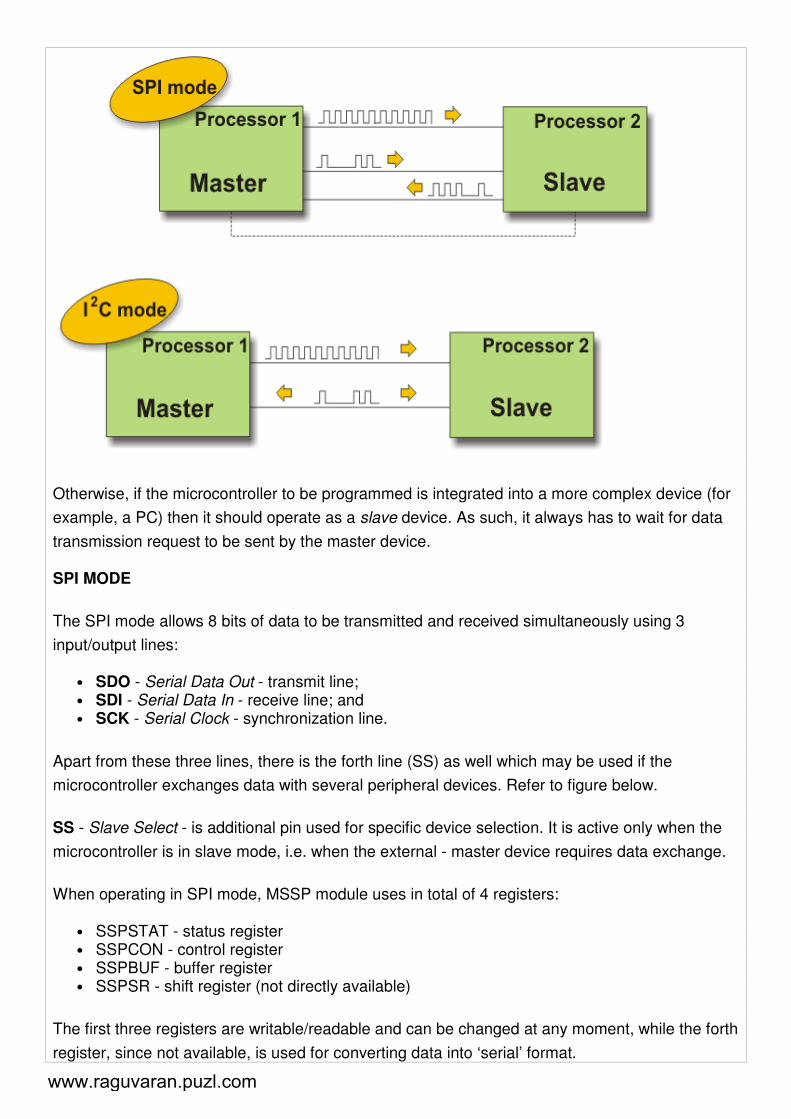
Otherwise, if the microcontroller to be programmed is integrated into a more complex device (for
example, a PC) then it should operate as a slave device. As such, it always has to wait for data
transmission request to be sent by the master device.
SPI MODE
The SPI mode allows 8 bits of data to be transmitted and received simultaneously using 3
input/output lines:
• SDO - Serial Data Out - transmit line; • SDI - Serial Data In - receive line; and • SCK - Serial Clock - synchronization line.
Apart from these three lines, there is the forth line (SS) as well which may be used if the
microcontroller exchanges data with several peripheral devices. Refer to figure below.
SS - Slave Select - is additional pin used for specific device selection. It is active only when the
microcontroller is in slave mode, i.e. when the external - master device requires data exchange.
When operating in SPI mode, MSSP module uses in total of 4 registers:
• SSPSTAT - status register • SSPCON - control register • SSPBUF - buffer register • SSPSR - shift register (not directly available)
The first three registers are writable/readable and can be changed at any moment, while the forth
register, since not available, is used for converting data into ‘serial’ format.
www.raguvaran.puzl.com
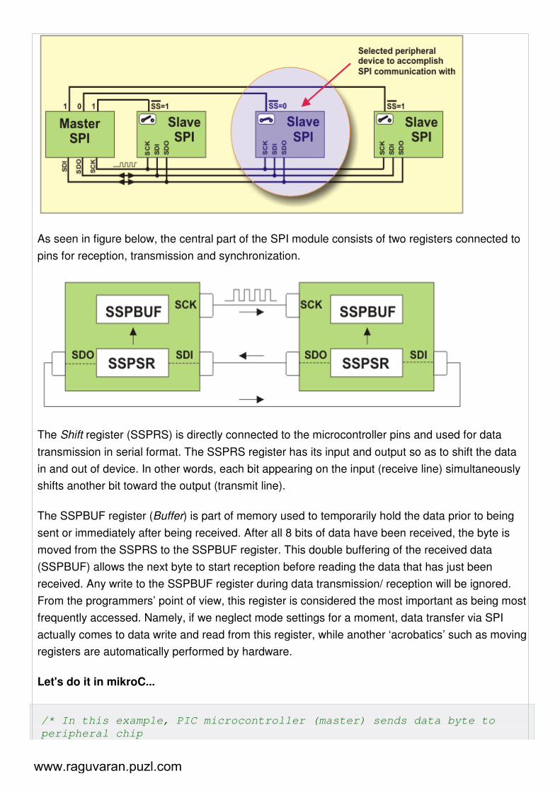
As seen in figure below, the central part of the SPI module consists of two registers connected to
pins for reception, transmission and synchronization.
The Shift register (SSPRS) is directly connected to the microcontroller pins and used for data
transmission in serial format. The SSPRS register has its input and output so as to shift the data
in and out of device. In other words, each bit appearing on the input (receive line) simultaneously
shifts another bit toward the output (transmit line).
The SSPBUF register (Buffer) is part of memory used to temporarily hold the data prior to being
sent or immediately after being received. After all 8 bits of data have been received, the byte is
moved from the SSPRS to the SSPBUF register. This double buffering of the received data
(SSPBUF) allows the next byte to start reception before reading the data that has just been
received. Any write to the SSPBUF register during data transmission/ reception will be ignored.
From the programmers’ point of view, this register is considered the most important as being most
frequently accessed. Namely, if we neglect mode settings for a moment, data transfer via SPI
actually comes to data write and read from this register, while another ‘acrobatics’ such as moving
registers are automatically performed by hardware.
Let's do it in mikroC...
/* In this example, PIC microcontroller (master) sends data byte to
peripheral chip
www.raguvaran.puzl.com
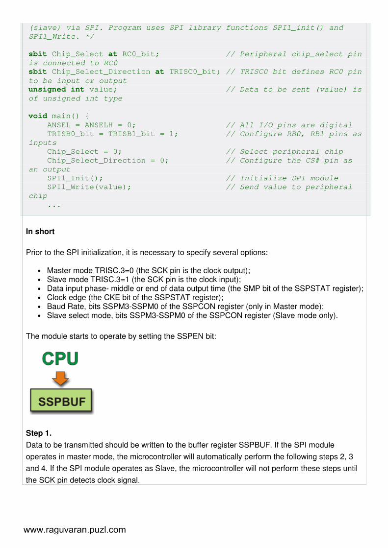
(slave) via SPI. Program uses SPI library functions SPI1_init() and
SPI1_Write. */
sbit Chip_Select at RC0_bit; // Peripheral chip_select pin
is connected to RC0
sbit Chip_Select_Direction at TRISC0_bit; // TRISC0 bit defines RC0 pin
to be input or output
unsigned int value; // Data to be sent (value) is
of unsigned int type
void main()
ANSEL = ANSELH = 0; // All I/O pins are digital
TRISB0_bit = TRISB1_bit = 1; // Configure RB0, RB1 pins as
inputs
Chip_Select = 0; // Select peripheral chip
Chip_Select_Direction = 0; // Configure the CS# pin as
an output
SPI1_Init(); // Initialize SPI module
SPI1_Write(value); // Send value to peripheral
chip
...
In short
Prior to the SPI initialization, it is necessary to specify several options:
• Master mode TRISC.3=0 (the SCK pin is the clock output); • Slave mode TRISC.3=1 (the SCK pin is the clock input); • Data input phase- middle or end of data output time (the SMP bit of the SSPSTAT register); • Clock edge (the CKE bit of the SSPSTAT register); • Baud Rate, bits SSPM3-SSPM0 of the SSPCON register (only in Master mode); • Slave select mode, bits SSPM3-SSPM0 of the SSPCON register (Slave mode only).
The module starts to operate by setting the SSPEN bit:
Step 1.
Data to be transmitted should be written to the buffer register SSPBUF. If the SPI module
operates in master mode, the microcontroller will automatically perform the following steps 2, 3
and 4. If the SPI module operates as Slave, the microcontroller will not perform these steps until
the SCK pin detects clock signal.
www.raguvaran.puzl.com
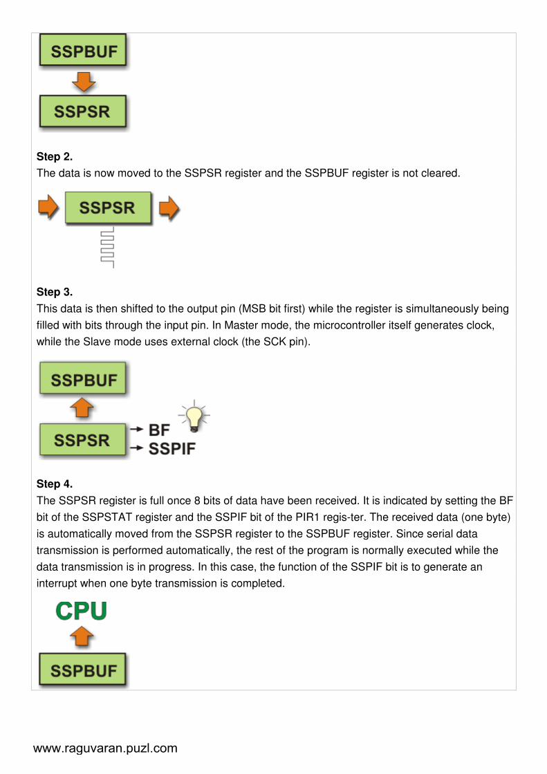
Step 2.
The data is now moved to the SSPSR register and the SSPBUF register is not cleared.
Step 3.
This data is then shifted to the output pin (MSB bit first) while the register is simultaneously being
filled with bits through the input pin. In Master mode, the microcontroller itself generates clock,
while the Slave mode uses external clock (the SCK pin).
Step 4.
The SSPSR register is full once 8 bits of data have been received. It is indicated by setting the BF
bit of the SSPSTAT register and the SSPIF bit of the PIR1 regis-ter. The received data (one byte)
is automatically moved from the SSPSR register to the SSPBUF register. Since serial data
transmission is performed automatically, the rest of the program is normally executed while the
data transmission is in progress. In this case, the function of the SSPIF bit is to generate an
interrupt when one byte transmission is completed.
www.raguvaran.puzl.com
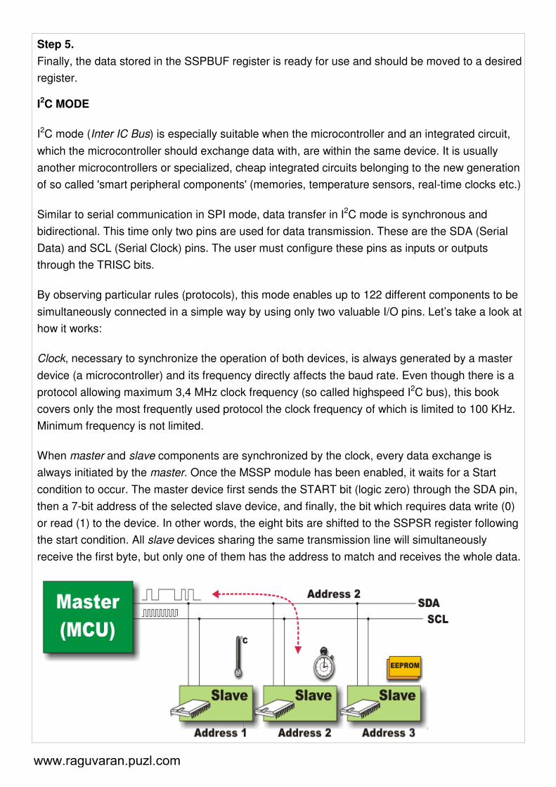
Step 5.
Finally, the data stored in the SSPBUF register is ready for use and should be moved to a desired
register.
I2C MODE
I2C mode (Inter IC Bus) is especially suitable when the microcontroller and an integrated circuit,
which the microcontroller should exchange data with, are within the same device. It is usually
another microcontrollers or specialized, cheap integrated circuits belonging to the new generation
of so called 'smart peripheral components' (memories, temperature sensors, real-time clocks etc.)
Similar to serial communication in SPI mode, data transfer in I2C mode is synchronous and
bidirectional. This time only two pins are used for data transmission. These are the SDA (Serial
Data) and SCL (Serial Clock) pins. The user must configure these pins as inputs or outputs
through the TRISC bits.
By observing particular rules (protocols), this mode enables up to 122 different components to be
simultaneously connected in a simple way by using only two valuable I/O pins. Let’s take a look at
how it works:
Clock, necessary to synchronize the operation of both devices, is always generated by a master
device (a microcontroller) and its frequency directly affects the baud rate. Even though there is a
protocol allowing maximum 3,4 MHz clock frequency (so called highspeed I2C bus), this book
covers only the most frequently used protocol the clock frequency of which is limited to 100 KHz.
Minimum frequency is not limited.
When master and slave components are synchronized by the clock, every data exchange is
always initiated by the master. Once the MSSP module has been enabled, it waits for a Start
condition to occur. The master device first sends the START bit (logic zero) through the SDA pin,
then a 7-bit address of the selected slave device, and finally, the bit which requires data write (0)
or read (1) to the device. In other words, the eight bits are shifted to the SSPSR register following
the start condition. All slave devices sharing the same transmission line will simultaneously
receive the first byte, but only one of them has the address to match and receives the whole data.
www.raguvaran.puzl.com
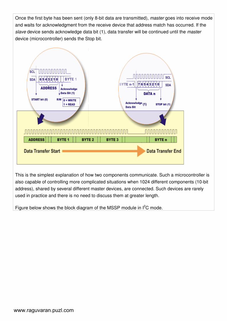
Once the first byte has been sent (only 8-bit data are transmitted), master goes into receive mode
and waits for acknowledgment from the receive device that address match has occurred. If the
slave device sends acknowledge data bit (1), data transfer will be continued until the master
device (microcontroller) sends the Stop bit.
This is the simplest explanation of how two components communicate. Such a microcontroller is
also capable of controlling more complicated situations when 1024 different components (10-bit
address), shared by several different master devices, are connected. Such devices are rarely
used in practice and there is no need to discuss them at greater length.
Figure below shows the block diagram of the MSSP module in I2C mode.
www.raguvaran.puzl.com
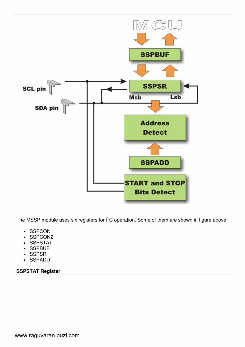
The MSSP module uses six registers for I2C operation. Some of them are shown in figure above:
• SSPCON • SSPCON2 • SSPSTAT • SSPBUF • SSPSR • SSPADD
SSPSTAT Register
www.raguvaran.puzl.com
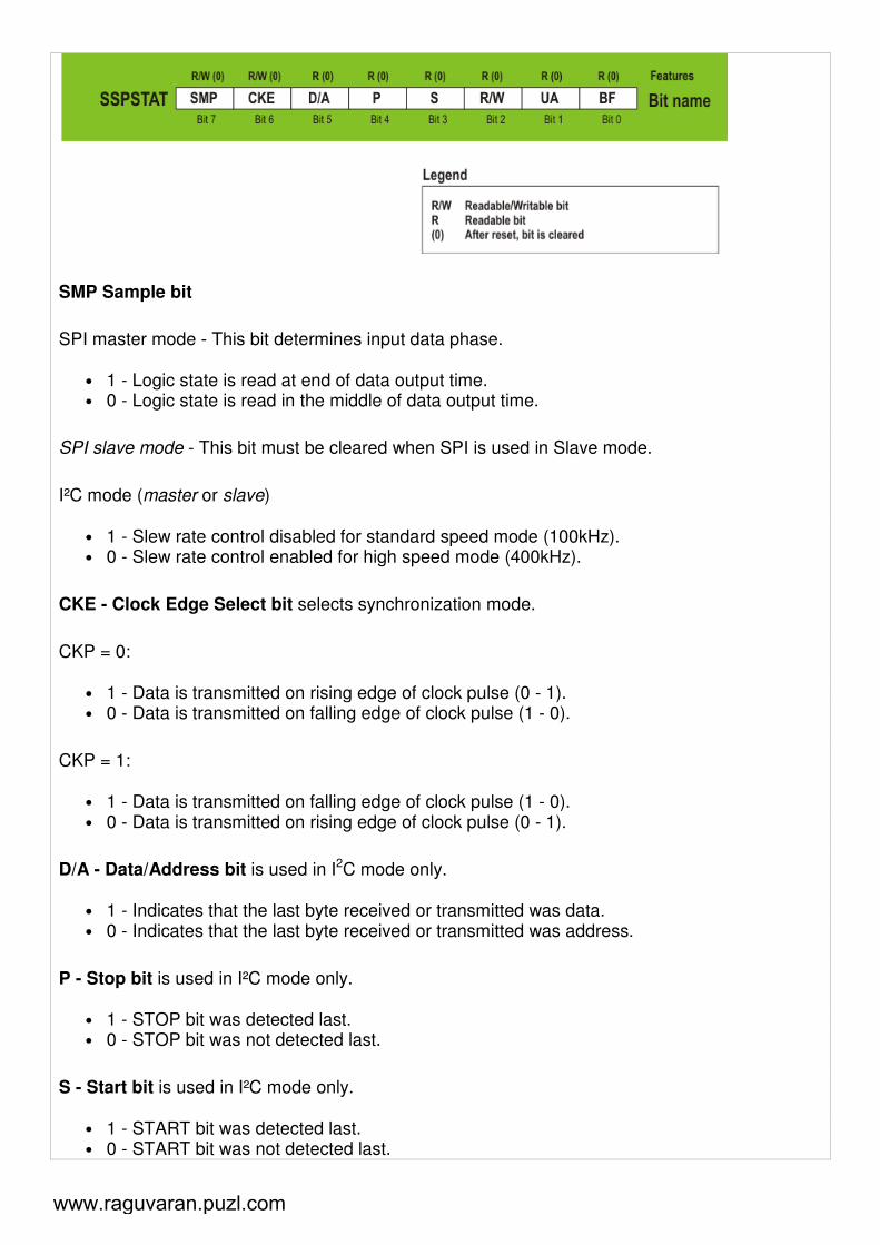
SMP Sample bit
SPI master mode - This bit determines input data phase.
• 1 - Logic state is read at end of data output time. • 0 - Logic state is read in the middle of data output time.
SPI slave mode - This bit must be cleared when SPI is used in Slave mode.
I²C mode (master or slave)
• 1 - Slew rate control disabled for standard speed mode (100kHz). • 0 - Slew rate control enabled for high speed mode (400kHz).
CKE - Clock Edge Select bit selects synchronization mode.
CKP = 0:
• 1 - Data is transmitted on rising edge of clock pulse (0 - 1). • 0 - Data is transmitted on falling edge of clock pulse (1 - 0).
CKP = 1:
• 1 - Data is transmitted on falling edge of clock pulse (1 - 0). • 0 - Data is transmitted on rising edge of clock pulse (0 - 1).
D/A - Data/Address bit is used in I2C mode only.
• 1 - Indicates that the last byte received or transmitted was data. • 0 - Indicates that the last byte received or transmitted was address.
P - Stop bit is used in I²C mode only.
• 1 - STOP bit was detected last. • 0 - STOP bit was not detected last.
S - Start bit is used in I²C mode only.
• 1 - START bit was detected last. • 0 - START bit was not detected last.
www.raguvaran.puzl.com
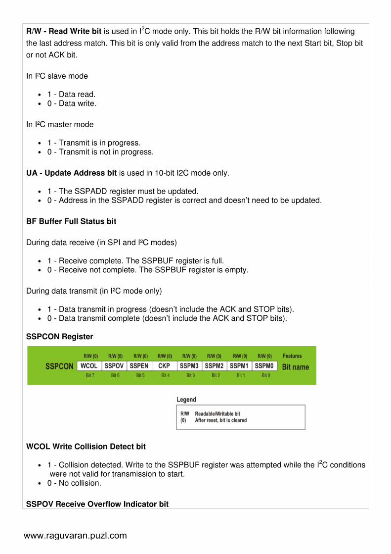
R/W - Read Write bit is used in I2C mode only. This bit holds the R/W bit information following
the last address match. This bit is only valid from the address match to the next Start bit, Stop bit
or not ACK bit.
In I²C slave mode
• 1 - Data read. • 0 - Data write.
In I²C master mode
• 1 - Transmit is in progress. • 0 - Transmit is not in progress.
UA - Update Address bit is used in 10-bit I2C mode only.
• 1 - The SSPADD register must be updated. • 0 - Address in the SSPADD register is correct and doesn’t need to be updated.
BF Buffer Full Status bit
During data receive (in SPI and I²C modes)
• 1 - Receive complete. The SSPBUF register is full. • 0 - Receive not complete. The SSPBUF register is empty.
During data transmit (in I²C mode only)
• 1 - Data transmit in progress (doesn’t include the ACK and STOP bits). • 0 - Data transmit complete (doesn’t include the ACK and STOP bits).
SSPCON Register
WCOL Write Collision Detect bit
• 1 - Collision detected. Write to the SSPBUF register was attempted while the I2C conditions were not valid for transmission to start.
• 0 - No collision.
SSPOV Receive Overflow Indicator bit
www.raguvaran.puzl.com
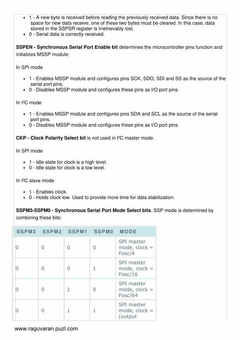
• 1 - A new byte is received before reading the previously received data. Since there is no space for new data receive, one of these two bytes must be cleared. In this case, data stored in the SSPSR register is irretrievably lost.
• 0 - Serial data is correctly received.
SSPEN - Synchronous Serial Port Enable bit determines the microcontroller pins function and
initializes MSSP module:
In SPI mode
• 1 - Enables MSSP module and configures pins SCK, SDO, SDI and SS as the source of the serial port pins.
• 0 - Disables MSSP module and configures these pins as I/O port pins.
In I²C mode
• 1 - Enables MSSP module and configures pins SDA and SCL as the source of the serial port pins.
• 0 - Disables MSSP module and configures these pins as I/O port pins.
CKP - Clock Polarity Select bit is not used in I²C master mode.
In SPI mode
• 1 - Idle state for clock is a high level. • 0 - Idle state for clock is a low level.
In I²C slave mode
• 1 - Enables clock. • 0 - Holds clock low. Used to provide more time for data stabilization.
SSPM3-SSPM0 - Synchronous Serial Port Mode Select bits. SSP mode is determined by
combining these bits:
SSPM3 SSPM2 SSPM1 SSPM0 MODE
0 0 0 0 SPI master mode, clock =
Fosc/4
0 0 0 1 SPI master mode, clock =
Fosc/16
0 0 1 0
SPI master
mode, clock = Fosc/64
0 0 1 1 SPI master mode, clock =
(output
www.raguvaran.puzl.com
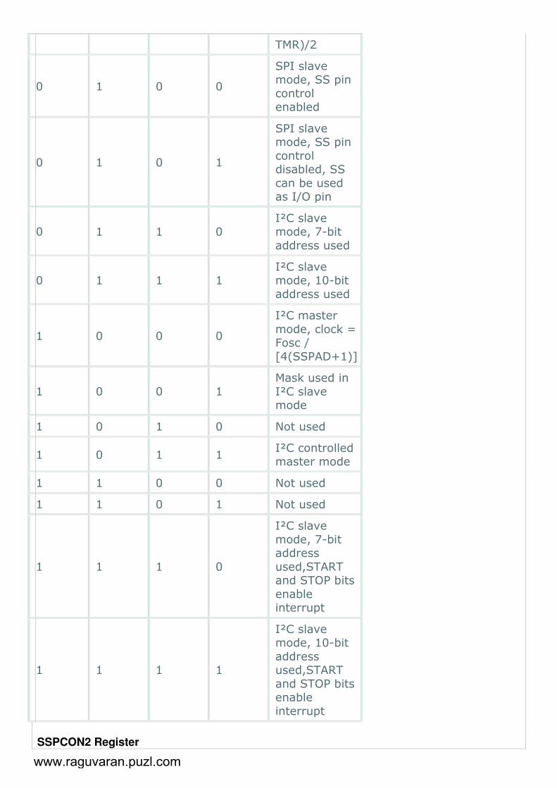
TMR)/2
0 1 0 0
SPI slave mode, SS pin
control enabled
0 1 0 1
SPI slave mode, SS pin
control disabled, SS
can be used as I/O pin
0 1 1 0 I²C slave mode, 7-bit
address used
0 1 1 1 I²C slave mode, 10-bit
address used
1 0 0 0
I²C master
mode, clock = Fosc /
[4(SSPAD+1)]
1 0 0 1
Mask used in
I²C slave mode
1 0 1 0 Not used
1 0 1 1 I²C controlled master mode
1 1 0 0 Not used
1 1 0 1 Not used
1 1 1 0
I²C slave
mode, 7-bit address
used,START and STOP bits
enable interrupt
1 1 1 1
I²C slave mode, 10-bit
address used,START
and STOP bits enable
interrupt
SSPCON2 Register
www.raguvaran.puzl.com

GCEN - General Call Enable bit
In I²C slave mode only
• 1 - Enables interrupt when a general call address (0000h) is received in the SSPSR. • 0 - General call address disabled.
ACKSTAT - Acknowledge Status bit
In I²C Master Transmit mode only
• 1 - Acknowledge was not received from slave. • 0 - Acknowledge was received from slave.
ACKDT - Acknowledge data bit
In I²C Master Receive mode only
• 1 - Not Acknowledge. • 0 - Acknowledge.
ACKEN - Acknowledge Sequence Enable bit
In I²C Master Receive mode
• 1 - Initiate acknowledge condition on the SDA and SCL pins and transmit the ACKDT data bit. It is automatically cleared by hardware.
• 0 - Acknowledge condition is not initiated.
RCEN - Receive Enable bit
In I²C Master mode only
• 1 - Enables data receive in I2C mode. • 0 - Receive disabled.
PEN - STOP condition Enable bit
In I²C Master mode only
www.raguvaran.puzl.com
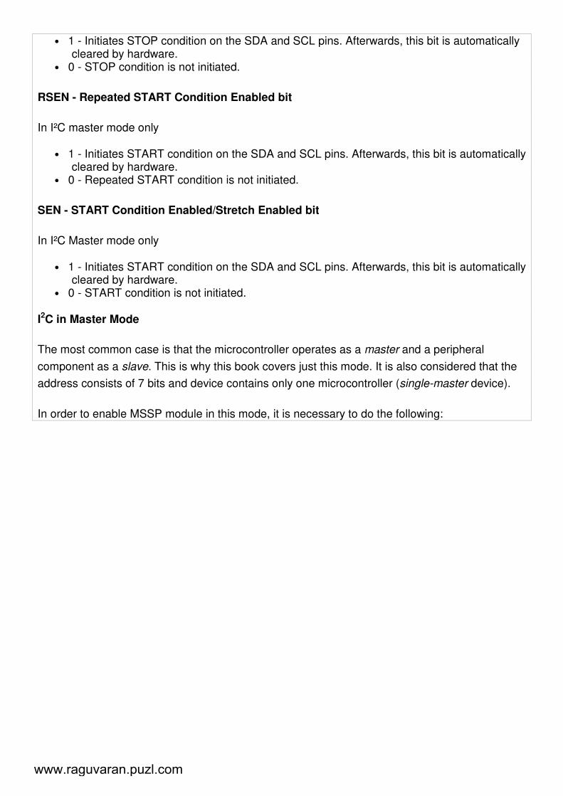
• 1 - Initiates STOP condition on the SDA and SCL pins. Afterwards, this bit is automatically cleared by hardware.
• 0 - STOP condition is not initiated.
RSEN - Repeated START Condition Enabled bit
In I²C master mode only
• 1 - Initiates START condition on the SDA and SCL pins. Afterwards, this bit is automatically cleared by hardware.
• 0 - Repeated START condition is not initiated.
SEN - START Condition Enabled/Stretch Enabled bit
In I²C Master mode only
• 1 - Initiates START condition on the SDA and SCL pins. Afterwards, this bit is automatically cleared by hardware.
• 0 - START condition is not initiated.
I2C in Master Mode
The most common case is that the microcontroller operates as a master and a peripheral
component as a slave. This is why this book covers just this mode. It is also considered that the
address consists of 7 bits and device contains only one microcontroller (single-master device).
In order to enable MSSP module in this mode, it is necessary to do the following:
www.raguvaran.puzl.com
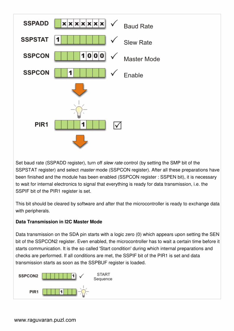
Set baud rate (SSPADD register), turn off slew rate control (by setting the SMP bit of the
SSPSTAT register) and select master mode (SSPCON register). After all these preparations have
been finished and the module has been enabled (SSPCON register : SSPEN bit), it is necessary
to wait for internal electronics to signal that everything is ready for data transmission, i.e. the
SSPIF bit of the PIR1 register is set.
This bit should be cleared by software and after that the microcontroller is ready to exchange data
with peripherals.
Data Transmission in I2C Master Mode
Data transmission on the SDA pin starts with a logic zero (0) which appears upon setting the SEN
bit of the SSPCON2 register. Even enabled, the microcontroller has to wait a certain time before it
starts communication. It is the so called 'Start condition' during which internal preparations and
checks are performed. If all conditions are met, the SSPIF bit of the PIR1 is set and data
transmission starts as soon as the SSPBUF register is loaded.
www.raguvaran.puzl.com
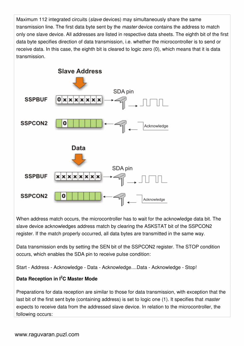
Maximum 112 integrated circuits (slave devices) may simultaneously share the same
transmission line. The first data byte sent by the master device contains the address to match
only one slave device. All addresses are listed in respective data sheets. The eighth bit of the first
data byte specifies direction of data transmission, i.e. whether the microcontroller is to send or
receive data. In this case, the eighth bit is cleared to logic zero (0), which means that it is data
transmission.
When address match occurs, the microcontroller has to wait for the acknowledge data bit. The
slave device acknowledges address match by clearing the ASKSTAT bit of the SSPCON2
register. If the match properly occurred, all data bytes are transmitted in the same way.
Data transmission ends by setting the SEN bit of the SSPCON2 register. The STOP condition
occurs, which enables the SDA pin to receive pulse condition:
Start - Address - Acknowledge - Data - Acknowledge....Data - Acknowledge - Stop!
Data Reception in I2C Master Mode
Preparations for data reception are similar to those for data transmission, with exception that the
last bit of the first sent byte (containing address) is set to logic one (1). It specifies that master
expects to receive data from the addressed slave device. In relation to the microcontroller, the
following occurs:
www.raguvaran.puzl.com
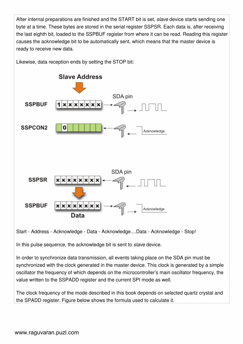
After internal preparations are finished and the START bit is set, slave device starts sending one
byte at a time. These bytes are stored in the serial register SSPSR. Each data is, after receiving
the last eighth bit, loaded to the SSPBUF register from where it can be read. Reading this register
causes the acknowledge bit to be automatically sent, which means that the master device is
ready to receive new data.
Likewise, data reception ends by setting the STOP bit:
Start - Address - Acknowledge - Data - Acknowledge....Data - Acknowledge - Stop!
In this pulse sequence, the acknowledge bit is sent to slave device.
In order to synchronize data transmission, all events taking place on the SDA pin must be
synchronized with the clock generated in the master device. This clock is generated by a simple
oscillator the frequency of which depends on the microcontroller’s main oscillator frequency, the
value written to the SSPADD register and the current SPI mode as well.
The clock frequency of the mode described in this book depends on selected quartz crystal and
the SPADD register. Figure below shows the formula used to calculate it.
www.raguvaran.puzl.com
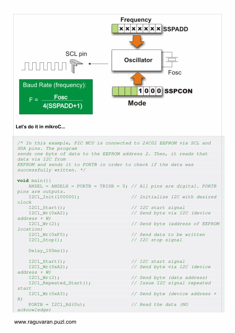
Let's do it in mikroC...
/* In this example, PIC MCU is connected to 24C02 EEPROM via SCL and
SDA pins. The program
sends one byte of data to the EEPROM address 2. Then, it reads that
data via I2C from
EEPROM and sends it to PORTB in order to check if the data was
successfully written. */
void main()
ANSEL = ANSELH = PORTB = TRISB = 0; // All pins are digital. PORTB
pins are outputs.
I2C1_Init(100000); // Initialize I2C with desired
clock
I2C1_Start(); // I2C start signal
I2C1_Wr(0xA2); // Send byte via I2C (device
address + W)
I2C1_Wr(2); // Send byte (address of EEPROM
location)
I2C1_Wr(0xF0); // Send data to be written
I2C1_Stop(); // I2C stop signal
Delay_100ms();
I2C1_Start(); // I2C start signal
I2C1_Wr(0xA2); // Send byte via I2C (device
address + W)
I2C1_Wr(2); // Send byte (data address)
I2C1_Repeated_Start(); // Issue I2C signal repeated
start
I2C1_Wr(0xA3); // Send byte (device address +
R)
PORTB = I2C1_Rd(0u); // Read the data (NO
acknowledge)
www.raguvaran.puzl.com
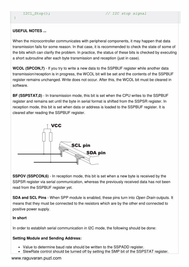
I2C1_Stop(); // I2C stop signal
USEFUL NOTES ...
When the microcontroller communicates with peripheral components, it may happen that data
transmission fails for some reason. In that case, it is recommended to check the state of some of
the bits which can clarify the problem. In practice, the status of these bits is checked by executing
a short subroutine after each byte transmission and reception (just in case).
WCOL (SPCON,7) - If you try to write a new data to the SSPBUF register while another data
transmission/reception is in progress, the WCOL bit will be set and the contents of the SSPBUF
register remains unchanged. Write does not occur. After this, the WCOL bit must be cleared in
software.
BF (SSPSTAT,0) - In transmission mode, this bit is set when the CPU writes to the SSPBUF
register and remains set until the byte in serial format is shifted from the SSPSR register. In
reception mode, this bit is set when data or address is loaded to the SSPBUF register. It is
cleared after reading the SSPBUF register.
SSPOV (SSPCON,6) - In reception mode, this bit is set when a new byte is received by the
SSPSR register via serial communication, whereas the previously received data has not been
read from the SSPBUF register yet.
SDA and SCL Pins - When SPP module is enabled, these pins turn into Open Drain outputs. It
means that they must be connected to the resistors which are by the other end connected to
positive power supply.
In short
In order to establish serial communication in I2C mode, the following should be done:
Setting Module and Sending Address:
• Value to determine baud rate should be written to the SSPADD register. • SlewRate control should be turned off by setting the SMP bit of the SSPSTAT register.
www.raguvaran.puzl.com
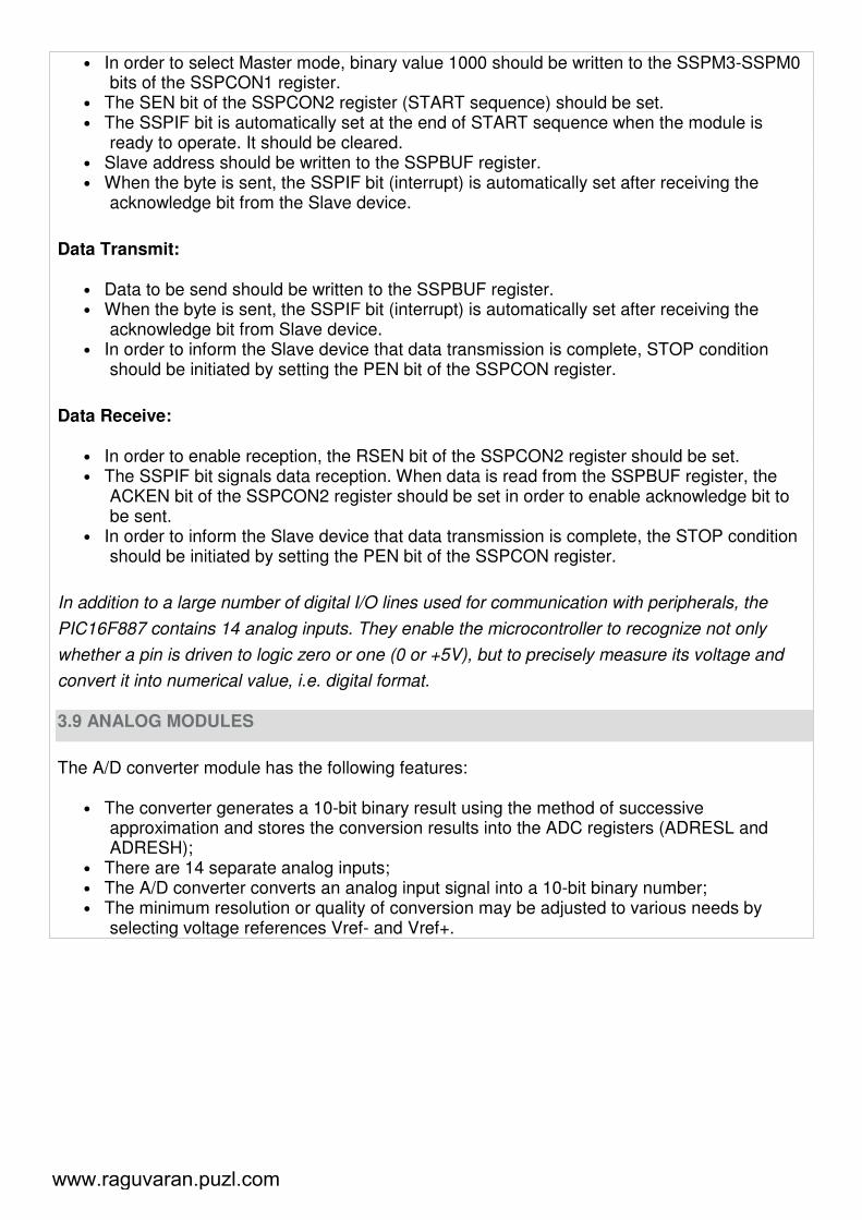
• In order to select Master mode, binary value 1000 should be written to the SSPM3-SSPM0 bits of the SSPCON1 register.
• The SEN bit of the SSPCON2 register (START sequence) should be set. • The SSPIF bit is automatically set at the end of START sequence when the module is
ready to operate. It should be cleared. • Slave address should be written to the SSPBUF register. • When the byte is sent, the SSPIF bit (interrupt) is automatically set after receiving the
acknowledge bit from the Slave device.
Data Transmit:
• Data to be send should be written to the SSPBUF register. • When the byte is sent, the SSPIF bit (interrupt) is automatically set after receiving the
acknowledge bit from Slave device. • In order to inform the Slave device that data transmission is complete, STOP condition
should be initiated by setting the PEN bit of the SSPCON register.
Data Receive:
• In order to enable reception, the RSEN bit of the SSPCON2 register should be set. • The SSPIF bit signals data reception. When data is read from the SSPBUF register, the
ACKEN bit of the SSPCON2 register should be set in order to enable acknowledge bit to be sent.
• In order to inform the Slave device that data transmission is complete, the STOP condition should be initiated by setting the PEN bit of the SSPCON register.
In addition to a large number of digital I/O lines used for communication with peripherals, the
PIC16F887 contains 14 analog inputs. They enable the microcontroller to recognize not only
whether a pin is driven to logic zero or one (0 or +5V), but to precisely measure its voltage and
convert it into numerical value, i.e. digital format.
3.9 ANALOG MODULES
The A/D converter module has the following features:
• The converter generates a 10-bit binary result using the method of successive approximation and stores the conversion results into the ADC registers (ADRESL and ADRESH);
• There are 14 separate analog inputs; • The A/D converter converts an analog input signal into a 10-bit binary number; • The minimum resolution or quality of conversion may be adjusted to various needs by
selecting voltage references Vref- and Vref+.
www.raguvaran.puzl.com
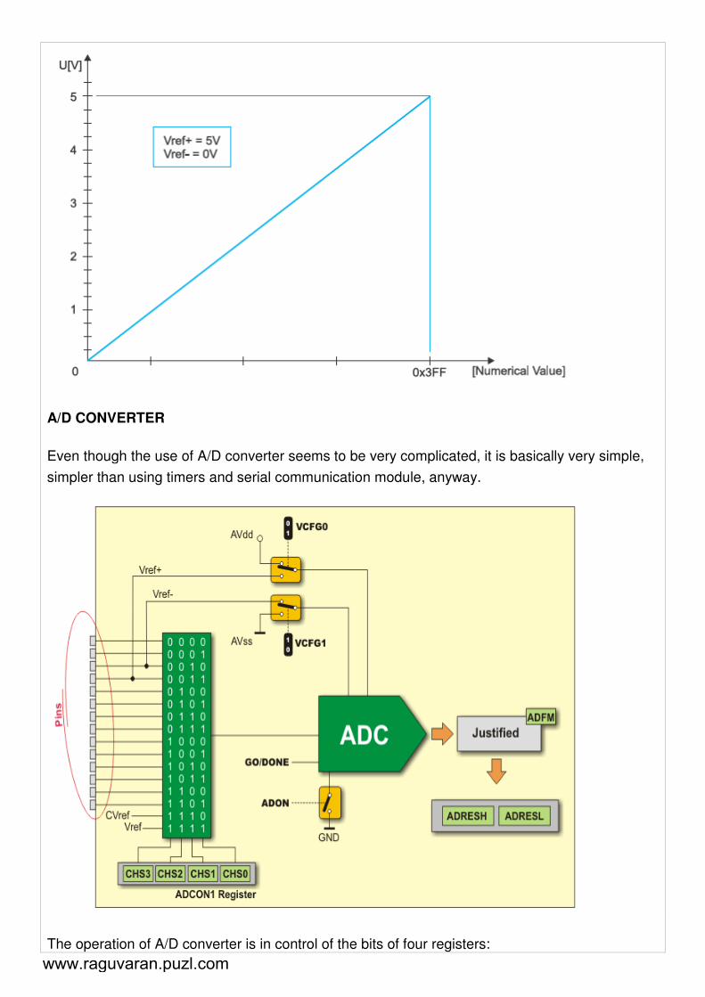
A/D CONVERTER
Even though the use of A/D converter seems to be very complicated, it is basically very simple,
simpler than using timers and serial communication module, anyway.
The operation of A/D converter is in control of the bits of four registers:
www.raguvaran.puzl.com
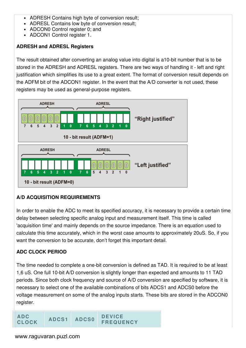
• ADRESH Contains high byte of conversion result; • ADRESL Contains low byte of conversion result; • ADCON0 Control register 0; and • ADCON1 Control register 1.
ADRESH and ADRESL Registers
The result obtained after converting an analog value into digital is a10-bit number that is to be
stored in the ADRESH and ADRESL registers. There are two ways of handling it - left and right
justification which simplifies its use to a great extent. The format of conversion result depends on
the ADFM bit of the ADCON1 register. In the event that the A/D converter is not used, these
registers may be used as general-purpose registers.
A/D ACQUISITION REQUIREMENTS
In order to enable the ADC to meet its specified accuracy, it is necessary to provide a certain time
delay between selecting specific analog input and measurement itself. This time is called
'acquisition time' and mainly depends on the source impedance. There is an equation used to
calculate this time accurately, which in the worst case amounts to approximately 20uS. So, if you
want the conversion to be accurate, don’t forget this important detail.
ADC CLOCK PERIOD
The time needed to complete a one-bit conversion is defined as TAD. It is required to be at least
1,6 uS. One full 10-bit A/D conversion is slightly longer than expected and amounts to 11 TAD
periods. Since both clock frequency and source of A/D conversion are specified by software, it is
necessary to select one of the available combinations of bits ADCS1 and ADCS0 before the
voltage measurement on some of the analog inputs starts. These bits are stored in the ADCON0
register.
ADC CLOCK
ADCS1 ADCS0 DEVICE FREQUENCY
www.raguvaran.puzl.com
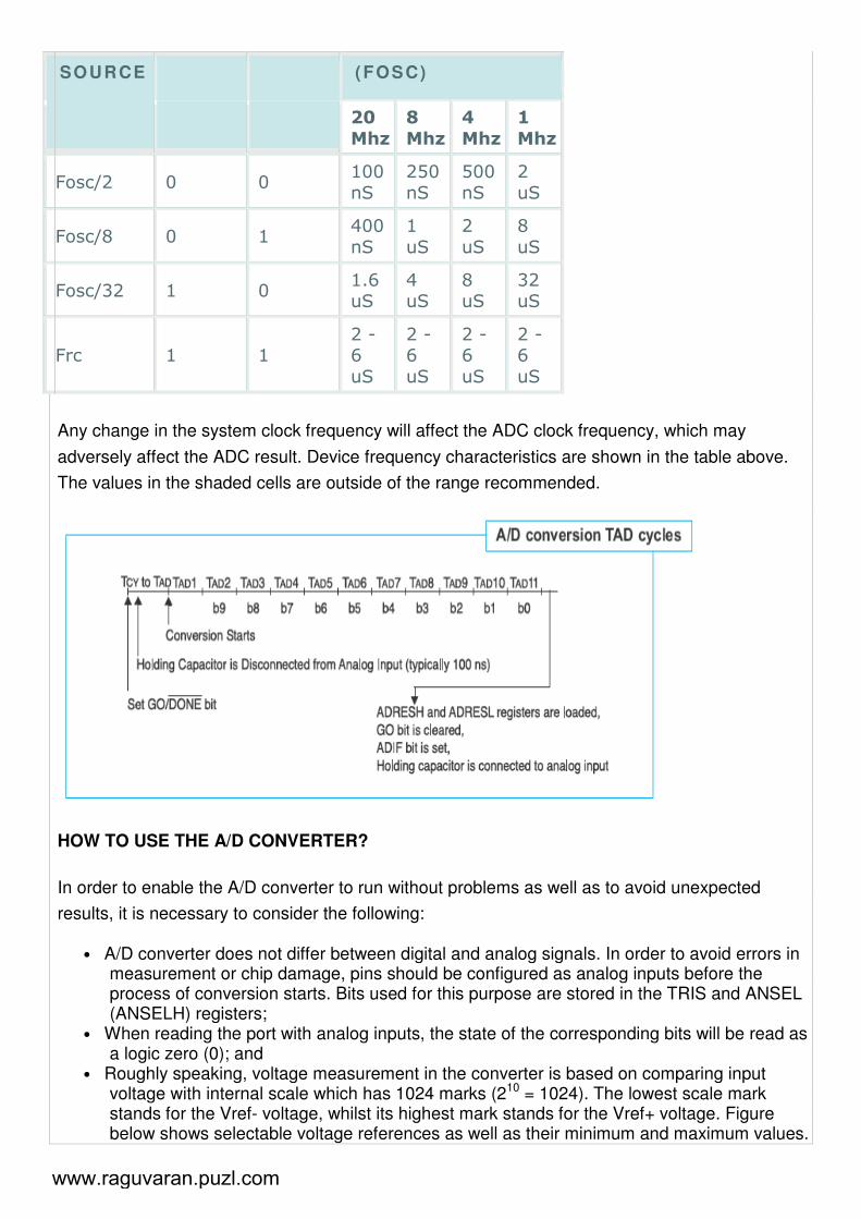
SOURCE (FOSC)
20
Mhz
8
Mhz
4
Mhz
1
Mhz
Fosc/2 0 0 100
nS
250
nS
500
nS
2
uS
Fosc/8 0 1 400
nS
1
uS
2
uS
8
uS
Fosc/32 1 0 1.6 uS
4 uS
8 uS
32 uS
Frc 1 1 2 - 6
uS
2 - 6
uS
2 - 6
uS
2 - 6
uS
Any change in the system clock frequency will affect the ADC clock frequency, which may
adversely affect the ADC result. Device frequency characteristics are shown in the table above.
The values in the shaded cells are outside of the range recommended.
HOW TO USE THE A/D CONVERTER?
In order to enable the A/D converter to run without problems as well as to avoid unexpected
results, it is necessary to consider the following:
• A/D converter does not differ between digital and analog signals. In order to avoid errors in measurement or chip damage, pins should be configured as analog inputs before the process of conversion starts. Bits used for this purpose are stored in the TRIS and ANSEL (ANSELH) registers;
• When reading the port with analog inputs, the state of the corresponding bits will be read as a logic zero (0); and
• Roughly speaking, voltage measurement in the converter is based on comparing input voltage with internal scale which has 1024 marks (210 = 1024). The lowest scale mark stands for the Vref- voltage, whilst its highest mark stands for the Vref+ voltage. Figure below shows selectable voltage references as well as their minimum and maximum values.
www.raguvaran.puzl.com
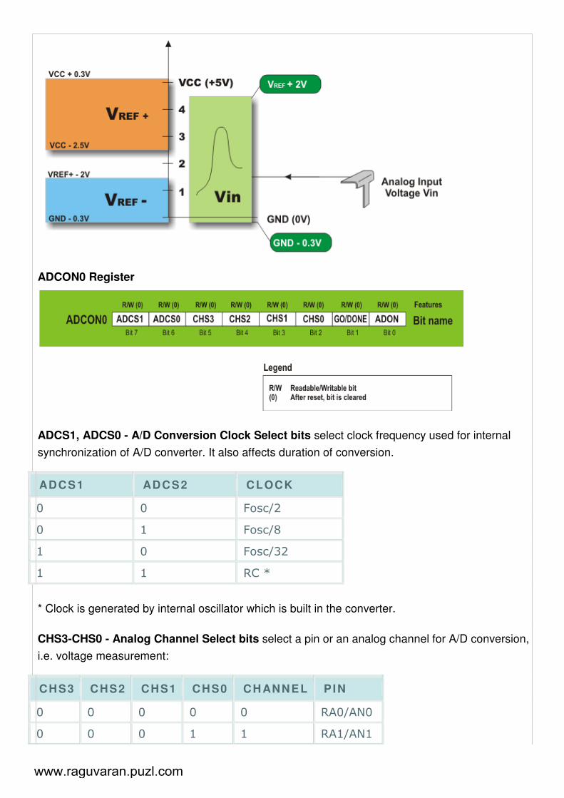
ADCON0 Register
ADCS1, ADCS0 - A/D Conversion Clock Select bits select clock frequency used for internal
synchronization of A/D converter. It also affects duration of conversion.
ADCS1 ADCS2 CLOCK
0 0 Fosc/2
0 1 Fosc/8
1 0 Fosc/32
1 1 RC *
* Clock is generated by internal oscillator which is built in the converter.
CHS3-CHS0 - Analog Channel Select bits select a pin or an analog channel for A/D conversion,
i.e. voltage measurement:
CHS3 CHS2 CHS1 CHS0 CHANNEL PIN
0 0 0 0 0 RA0/AN0
0 0 0 1 1 RA1/AN1
www.raguvaran.puzl.com
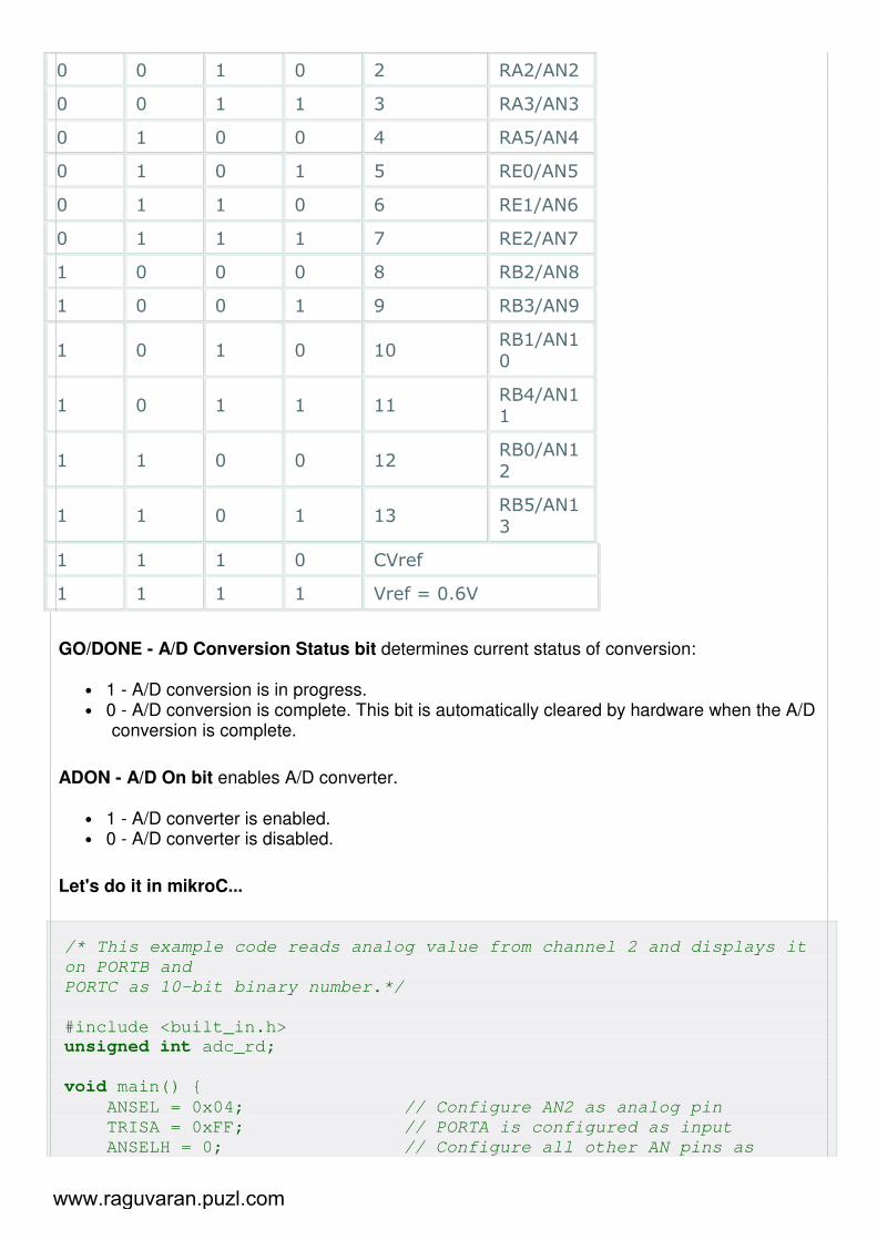
0 0 1 0 2 RA2/AN2
0 0 1 1 3 RA3/AN3
0 1 0 0 4 RA5/AN4
0 1 0 1 5 RE0/AN5
0 1 1 0 6 RE1/AN6
0 1 1 1 7 RE2/AN7
1 0 0 0 8 RB2/AN8
1 0 0 1 9 RB3/AN9
1 0 1 0 10 RB1/AN10
1 0 1 1 11 RB4/AN11
1 1 0 0 12 RB0/AN1
2
1 1 0 1 13 RB5/AN1
3
1 1 1 0 CVref
1 1 1 1 Vref = 0.6V
GO/DONE - A/D Conversion Status bit determines current status of conversion:
• 1 - A/D conversion is in progress. • 0 - A/D conversion is complete. This bit is automatically cleared by hardware when the A/D
conversion is complete.
ADON - A/D On bit enables A/D converter.
• 1 - A/D converter is enabled. • 0 - A/D converter is disabled.
Let's do it in mikroC...
/* This example code reads analog value from channel 2 and displays it
on PORTB and
PORTC as 10-bit binary number.*/
#include <built_in.h>
unsigned int adc_rd;
void main()
ANSEL = 0x04; // Configure AN2 as analog pin
TRISA = 0xFF; // PORTA is configured as input
ANSELH = 0; // Configure all other AN pins as
www.raguvaran.puzl.com
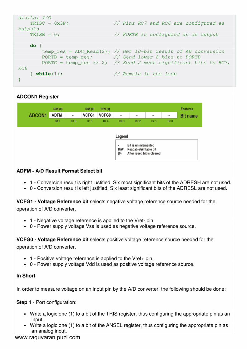
digital I/O
TRISC = 0x3F; // Pins RC7 and RC6 are configured as
outputs
TRISB = 0; // PORTB is configured as an output
do
temp_res = ADC_Read(2); // Get 10-bit result of AD conversion
PORTB = temp_res; // Send lower 8 bits to PORTB
PORTC = temp_res >> 2; // Send 2 most significant bits to RC7,
RC6
while(1); // Remain in the loop
ADCON1 Register
ADFM - A/D Result Format Select bit
• 1 - Conversion result is right justified. Six most significant bits of the ADRESH are not used. • 0 - Conversion result is left justified. Six least significant bits of the ADRESL are not used.
VCFG1 - Voltage Reference bit selects negative voltage reference source needed for the
operation of A/D converter.
• 1 - Negative voltage reference is applied to the Vref- pin. • 0 - Power supply voltage Vss is used as negative voltage reference source.
VCFG0 - Voltage Reference bit selects positive voltage reference source needed for the
operation of A/D converter.
• 1 - Positive voltage reference is applied to the Vref+ pin. • 0 - Power supply voltage Vdd is used as positive voltage reference source.
In Short
In order to measure voltage on an input pin by the A/D converter, the following should be done:
Step 1 - Port configuration:
• Write a logic one (1) to a bit of the TRIS register, thus configuring the appropriate pin as an input.
• Write a logic one (1) to a bit of the ANSEL register, thus configuring the appropriate pin as an analog input.
www.raguvaran.puzl.com
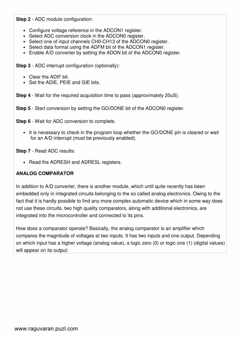
Step 2 - ADC module configuration:
• Configure voltage reference in the ADCON1 register. • Select ADC conversion clock in the ADCON0 register. • Select one of input channels CH0-CH13 of the ADCON0 register. • Select data format using the ADFM bit of the ADCON1 register. • Enable A/D converter by setting the ADON bit of the ADCON0 register.
Step 3 - ADC interrupt configuration (optionally):
• Clear the ADIF bit. • Set the ADIE, PEIE and GIE bits.
Step 4 - Wait for the required acquisition time to pass (approximately 20uS).
Step 5 - Start conversion by setting the GO/DONE bit of the ADCON0 register.
Step 6 - Wait for ADC conversion to complete.
• It is necessary to check in the program loop whether the GO/DONE pin is cleared or wait for an A/D interrupt (must be previously enabled).
Step 7 - Read ADC results:
• Read the ADRESH and ADRESL registers.
ANALOG COMPARATOR
In addition to A/D converter, there is another module, which until quite recently has been
embedded only in integrated circuits belonging to the so called analog electronics. Owing to the
fact that it is hardly possible to find any more complex automatic device which in some way does
not use these circuits, two high quality comparators, along with additional electronics, are
integrated into the microcontroller and connected to its pins.
How does a comparator operate? Basically, the analog comparator is an amplifier which
compares the magnitude of voltages at two inputs. It has two inputs and one output. Depending
on which input has a higher voltage (analog value), a logic zero (0) or logic one (1) (digital values)
will appear on its output:
www.raguvaran.puzl.com
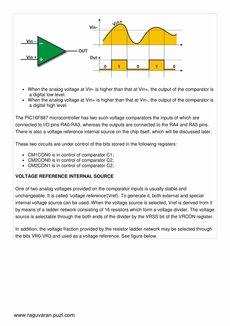
• When the analog voltage at Vin- is higher than that at Vin+, the output of the comparator is a digital low level.
• When the analog voltage at Vin+ is higher than that at Vin-, the output of the comparator is a digital high level.
The PIC16F887 microcontroller has two such voltage comparators the inputs of which are
connected to I/O pins RA0-RA3, whereas the outputs are connected to the RA4 and RA5 pins.
There is also a voltage reference internal source on the chip itself, which will be discussed later.
These two circuits are under control of the bits stored in the following registers:
• CM1CON0 is in control of comparator C1; • CM2CON0 is in control of comparator C2; • CM2CON1 is in control of comparator C2;
VOLTAGE REFERENCE INTERNAL SOURCE
One of two analog voltages provided on the comparator inputs is usually stable and
unchangeable. It is called 'voltage reference'(Vref). To generate it, both external and special
internal voltage source can be used. When the voltage source is selected, Vref is derived from it
by means of a ladder network consisting of 16 resistors which form a voltage divider. The voltage
source is selectable through the both ends of the divider by the VRSS bit of the VRCON register.
In addition, the voltage fraction provided by the resistor ladder network may be selected through
the bits VR0-VR3 and used as a voltage reference. See figure below.
www.raguvaran.puzl.com
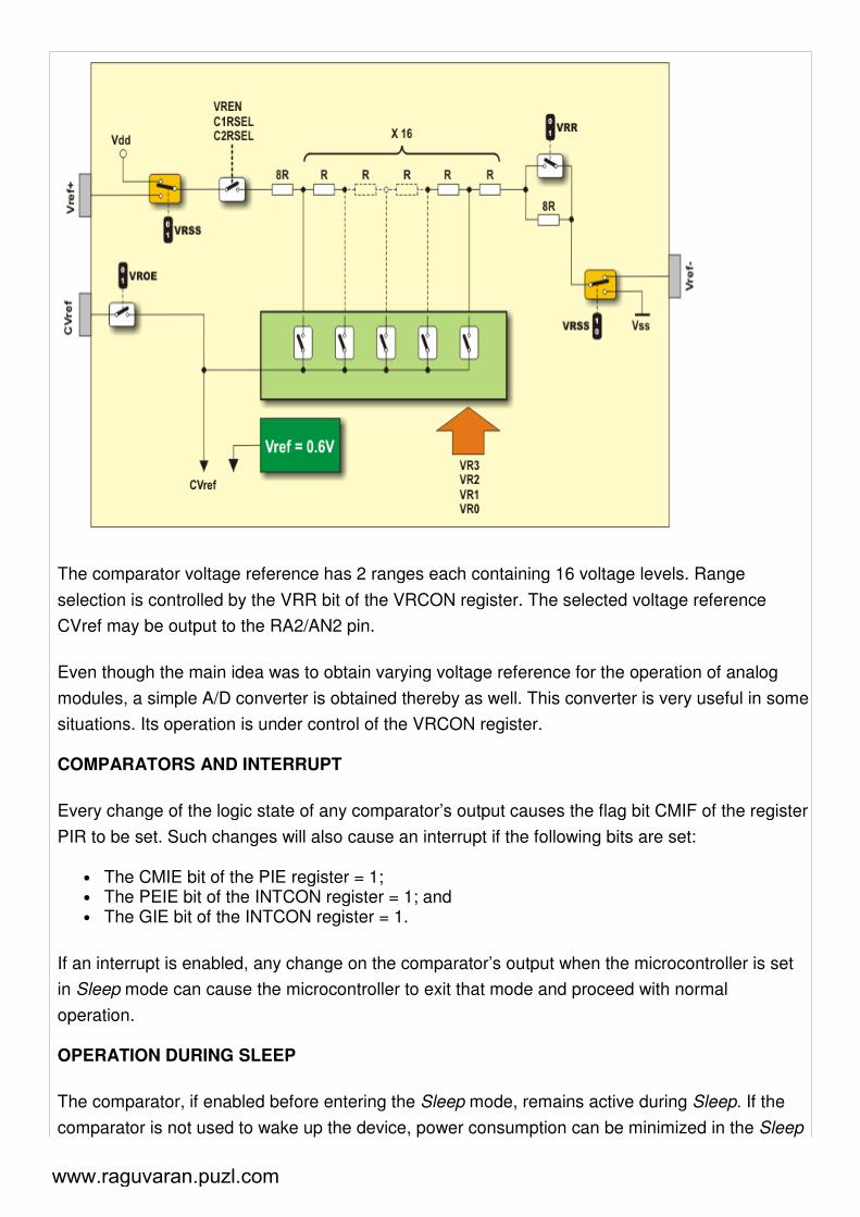
The comparator voltage reference has 2 ranges each containing 16 voltage levels. Range
selection is controlled by the VRR bit of the VRCON register. The selected voltage reference
CVref may be output to the RA2/AN2 pin.
Even though the main idea was to obtain varying voltage reference for the operation of analog
modules, a simple A/D converter is obtained thereby as well. This converter is very useful in some
situations. Its operation is under control of the VRCON register.
COMPARATORS AND INTERRUPT
Every change of the logic state of any comparator’s output causes the flag bit CMIF of the register
PIR to be set. Such changes will also cause an interrupt if the following bits are set:
• The CMIE bit of the PIE register = 1; • The PEIE bit of the INTCON register = 1; and • The GIE bit of the INTCON register = 1.
If an interrupt is enabled, any change on the comparator’s output when the microcontroller is set
in Sleep mode can cause the microcontroller to exit that mode and proceed with normal
operation.
OPERATION DURING SLEEP
The comparator, if enabled before entering the Sleep mode, remains active during Sleep. If the
comparator is not used to wake up the device, power consumption can be minimized in the Sleep
www.raguvaran.puzl.com
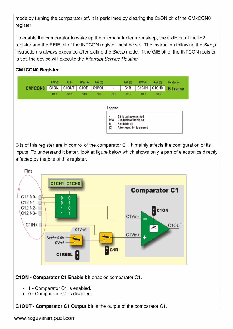
mode by turning the comparator off. It is performed by clearing the CxON bit of the CMxCON0
register.
To enable the comparator to wake up the microcontroller from sleep, the CxIE bit of the IE2
register and the PEIE bit of the INTCON register must be set. The instruction following the Sleep
instruction is always executed after exiting the Sleep mode. If the GIE bit of the INTCON register
is set, the device will execute the Interrupt Service Routine.
CM1CON0 Register
Bits of this register are in control of the comparator C1. It mainly affects the configuration of its
inputs. To understand it better, look at figure below which shows only a part of electronics directly
affected by the bits of this register.
C1ON - Comparator C1 Enable bit enables comparator C1.
• 1 - Comparator C1 is enabled. • 0 - Comparator C1 is disabled.
C1OUT - Comparator C1 Output bit is the output of the comparator C1.
www.raguvaran.puzl.com
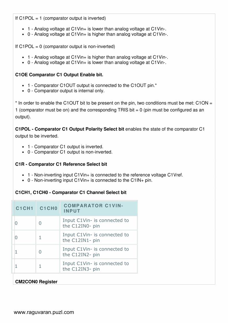
If C1POL = 1 (comparator output is inverted)
• 1 - Analog voltage at C1Vin+ is lower than analog voltage at C1Vin-. • 0 - Analog voltage at C1Vin+ is higher than analog voltage at C1Vin-.
If C1POL = 0 (comparator output is non-inverted)
• 1 - Analog voltage at C1Vin+ is higher than analog voltage at C1Vin-. • 0 - Analog voltage at C1Vin+ is lower than analog voltage at C1Vin-.
C1OE Comparator C1 Output Enable bit.
• 1 - Comparator C1OUT output is connected to the C1OUT pin.* • 0 - Comparator output is internal only.
* In order to enable the C1OUT bit to be present on the pin, two conditions must be met: C1ON =
1 (comparator must be on) and the corresponding TRIS bit = 0 (pin must be configured as an
output).
C1POL - Comparator C1 Output Polarity Select bit enables the state of the comparator C1
output to be inverted.
• 1 - Comparator C1 output is inverted. • 0 - Comparator C1 output is non-inverted.
C1R - Comparator C1 Reference Select bit
• 1 - Non-inverting input C1Vin+ is connected to the reference voltage C1Vref. • 0 - Non-inverting input C1Vin+ is connected to the C1IN+ pin.
C1CH1, C1CH0 - Comparator C1 Channel Select bit
C1CH1 C1CH0 COMP ARATOR C1VIN- INPUT
0 0 Input C1Vin- is connected to
the C12IN0- pin
0 1 Input C1Vin- is connected to
the C12IN1- pin
1 0 Input C1Vin- is connected to the C12IN2- pin
1 1 Input C1Vin- is connected to the C12IN3- pin
CM2CON0 Register
www.raguvaran.puzl.com
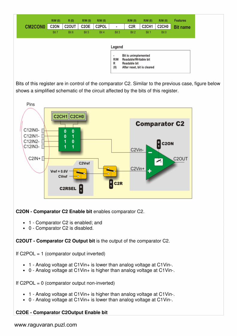
Bits of this register are in control of the comparator C2. Similar to the previous case, figure below
shows a simplified schematic of the circuit affected by the bits of this register.
C2ON - Comparator C2 Enable bit enables comparator C2.
• 1 - Comparator C2 is enabled; and • 0 - Comparator C2 is disabled.
C2OUT - Comparator C2 Output bit is the output of the comparator C2.
If C2POL = 1 (comparator output inverted)
• 1 - Analog voltage at C1Vin+ is lower than analog voltage at C1Vin-. • 0 - Analog voltage at C1Vin+ is higher than analog voltage at C1Vin-.
If C2POL = 0 (comparator output non-inverted)
• 1 - Analog voltage at C1Vin+ is higher than analog voltage at C1Vin-. • 0 - Analog voltage at C1Vin+ is lower than analog voltage at C1Vin-.
C2OE - Comparator C2Output Enable bit
www.raguvaran.puzl.com
• 1 - Comparator C2OUT output is connected to the C2OUT pin.* • 0 - Comparator output is internal only.
* In order to enable the C2OUT bit to be present on the pin, two conditions must be met: C2ON =
1 (comparator must be on) and the corresponding TRIS bit = 0 (pin must be configured as an
output).
C2POL - Comparator C2 Output Polarity Select bit enables the state of the comparator C2
output to be inverted.
• 1 - Comparator C2 output is inverted. • 0 - Comparator C2 output is non-inverted.
C2R - Comparator C2 Reference Select bit
• 1 - Non-inverting input C2Vin+ is connected to the reference voltage C2Vref. • 0 - Non-inverting input C2Vin+ is connected to the C2IN+ pin.
C2CH1, C2CH0 Comparator C2 Channel Select bit
C2CH1 C2CH0 COMP ARATOR C2VIN- INPUT
0 0 Input C2Vin- is connected to the C12IN0- pin
0 1 Input C2Vin- is connected to the C12IN1- pin
1 0 Input C2Vin- is connected to the C12IN2- pin
1 1 Input C2Vin- is connected to
the C12IN3- pin
CM2CON1 Register
MC1OUT Mirror Copy of C1OUT bit
MC2OUT Mirror Copy of C2OUT bit
www.raguvaran.puzl.com
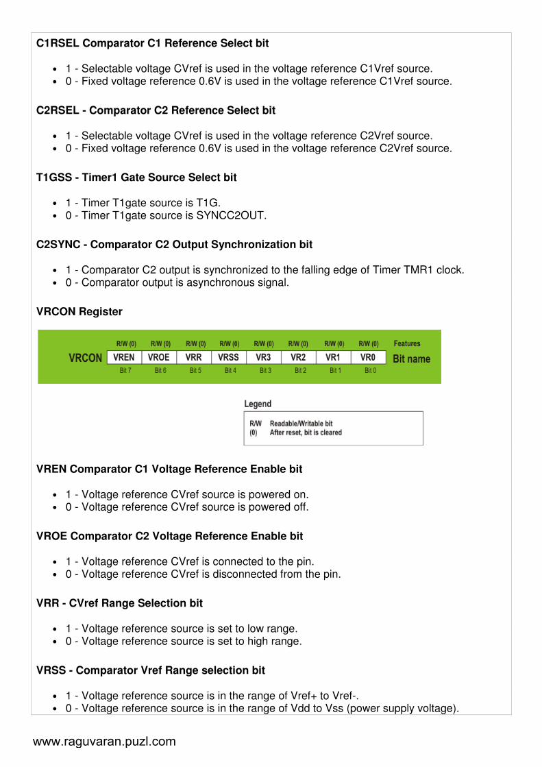
C1RSEL Comparator C1 Reference Select bit
• 1 - Selectable voltage CVref is used in the voltage reference C1Vref source. • 0 - Fixed voltage reference 0.6V is used in the voltage reference C1Vref source.
C2RSEL - Comparator C2 Reference Select bit
• 1 - Selectable voltage CVref is used in the voltage reference C2Vref source. • 0 - Fixed voltage reference 0.6V is used in the voltage reference C2Vref source.
T1GSS - Timer1 Gate Source Select bit
• 1 - Timer T1gate source is T1G. • 0 - Timer T1gate source is SYNCC2OUT.
C2SYNC - Comparator C2 Output Synchronization bit
• 1 - Comparator C2 output is synchronized to the falling edge of Timer TMR1 clock. • 0 - Comparator output is asynchronous signal.
VRCON Register
VREN Comparator C1 Voltage Reference Enable bit
• 1 - Voltage reference CVref source is powered on. • 0 - Voltage reference CVref source is powered off.
VROE Comparator C2 Voltage Reference Enable bit
• 1 - Voltage reference CVref is connected to the pin. • 0 - Voltage reference CVref is disconnected from the pin.
VRR - CVref Range Selection bit
• 1 - Voltage reference source is set to low range. • 0 - Voltage reference source is set to high range.
VRSS - Comparator Vref Range selection bit
• 1 - Voltage reference source is in the range of Vref+ to Vref-. • 0 - Voltage reference source is in the range of Vdd to Vss (power supply voltage).
www.raguvaran.puzl.com
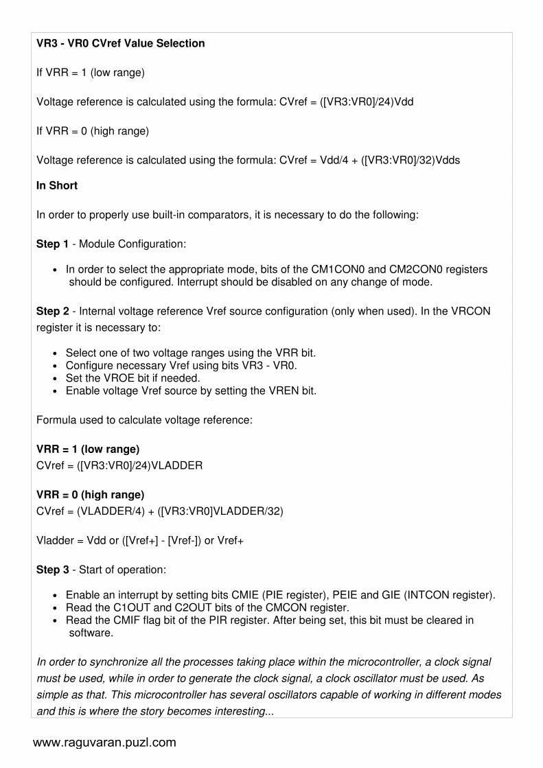
VR3 - VR0 CVref Value Selection
If VRR = 1 (low range)
Voltage reference is calculated using the formula: CVref = ([VR3:VR0]/24)Vdd
If VRR = 0 (high range)
Voltage reference is calculated using the formula: CVref = Vdd/4 + ([VR3:VR0]/32)Vdds
In Short
In order to properly use built-in comparators, it is necessary to do the following:
Step 1 - Module Configuration:
• In order to select the appropriate mode, bits of the CM1CON0 and CM2CON0 registers should be configured. Interrupt should be disabled on any change of mode.
Step 2 - Internal voltage reference Vref source configuration (only when used). In the VRCON
register it is necessary to:
• Select one of two voltage ranges using the VRR bit. • Configure necessary Vref using bits VR3 - VR0. • Set the VROE bit if needed. • Enable voltage Vref source by setting the VREN bit.
Formula used to calculate voltage reference:
VRR = 1 (low range)
CVref = ([VR3:VR0]/24)VLADDER
VRR = 0 (high range)
CVref = (VLADDER/4) + ([VR3:VR0]VLADDER/32)
Vladder = Vdd or ([Vref+] - [Vref-]) or Vref+
Step 3 - Start of operation:
• Enable an interrupt by setting bits CMIE (PIE register), PEIE and GIE (INTCON register). • Read the C1OUT and C2OUT bits of the CMCON register. • Read the CMIF flag bit of the PIR register. After being set, this bit must be cleared in
software.
In order to synchronize all the processes taking place within the microcontroller, a clock signal
must be used, while in order to generate the clock signal, a clock oscillator must be used. As
simple as that. This microcontroller has several oscillators capable of working in different modes
and this is where the story becomes interesting...
www.raguvaran.puzl.com
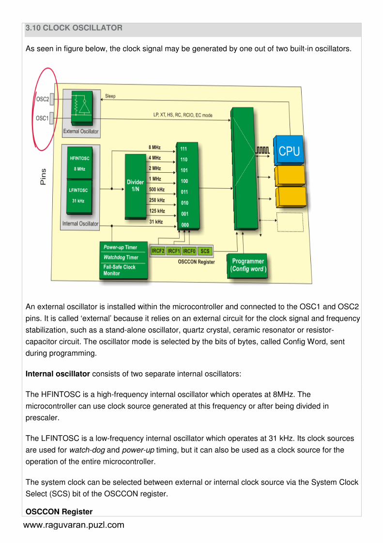
3.10 CLOCK OSCILLATOR
As seen in figure below, the clock signal may be generated by one out of two built-in oscillators.
An external oscillator is installed within the microcontroller and connected to the OSC1 and OSC2
pins. It is called ‘external’ because it relies on an external circuit for the clock signal and frequency
stabilization, such as a stand-alone oscillator, quartz crystal, ceramic resonator or resistor-
capacitor circuit. The oscillator mode is selected by the bits of bytes, called Config Word, sent
during programming.
Internal oscillator consists of two separate internal oscillators:
The HFINTOSC is a high-frequency internal oscillator which operates at 8MHz. The
microcontroller can use clock source generated at this frequency or after being divided in
prescaler.
The LFINTOSC is a low-frequency internal oscillator which operates at 31 kHz. Its clock sources
are used for watch-dog and power-up timing, but it can also be used as a clock source for the
operation of the entire microcontroller.
The system clock can be selected between external or internal clock source via the System Clock
Select (SCS) bit of the OSCCON register.
OSCCON Register
www.raguvaran.puzl.com
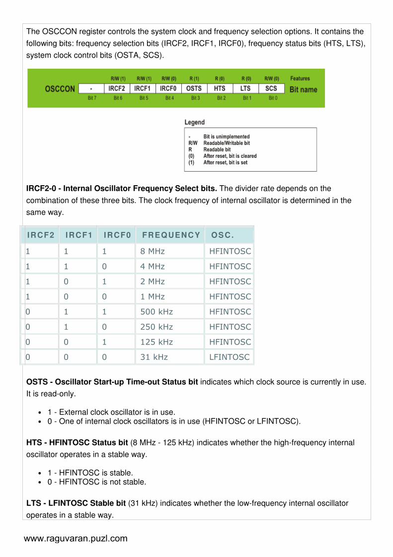
The OSCCON register controls the system clock and frequency selection options. It contains the
following bits: frequency selection bits (IRCF2, IRCF1, IRCF0), frequency status bits (HTS, LTS),
system clock control bits (OSTA, SCS).
IRCF2-0 - Internal Oscillator Frequency Select bits. The divider rate depends on the
combination of these three bits. The clock frequency of internal oscillator is determined in the
same way.
IRCF2 IRCF1 IRCF0 FREQUENCY OSC.
1 1 1 8 MHz HFINTOSC
1 1 0 4 MHz HFINTOSC
1 0 1 2 MHz HFINTOSC
1 0 0 1 MHz HFINTOSC
0 1 1 500 kHz HFINTOSC
0 1 0 250 kHz HFINTOSC
0 0 1 125 kHz HFINTOSC
0 0 0 31 kHz LFINTOSC
OSTS - Oscillator Start-up Time-out Status bit indicates which clock source is currently in use.
It is read-only.
• 1 - External clock oscillator is in use. • 0 - One of internal clock oscillators is in use (HFINTOSC or LFINTOSC).
HTS - HFINTOSC Status bit (8 MHz - 125 kHz) indicates whether the high-frequency internal
oscillator operates in a stable way.
• 1 - HFINTOSC is stable. • 0 - HFINTOSC is not stable.
LTS - LFINTOSC Stable bit (31 kHz) indicates whether the low-frequency internal oscillator
operates in a stable way.
www.raguvaran.puzl.com
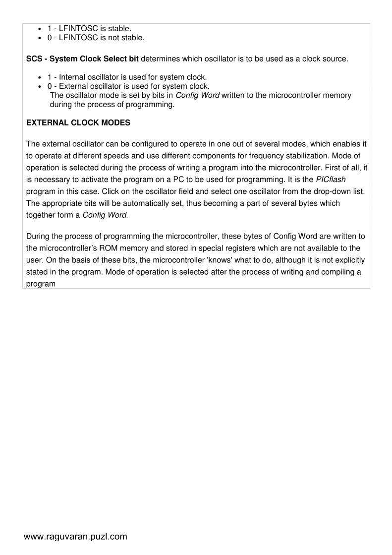
• 1 - LFINTOSC is stable. • 0 - LFINTOSC is not stable.
SCS - System Clock Select bit determines which oscillator is to be used as a clock source.
• 1 - Internal oscillator is used for system clock. • 0 - External oscillator is used for system clock.
The oscillator mode is set by bits in Config Word written to the microcontroller memory during the process of programming.
EXTERNAL CLOCK MODES
The external oscillator can be configured to operate in one out of several modes, which enables it
to operate at different speeds and use different components for frequency stabilization. Mode of
operation is selected during the process of writing a program into the microcontroller. First of all, it
is necessary to activate the program on a PC to be used for programming. It is the PICflash
program in this case. Click on the oscillator field and select one oscillator from the drop-down list.
The appropriate bits will be automatically set, thus becoming a part of several bytes which
together form a Config Word.
During the process of programming the microcontroller, these bytes of Config Word are written to
the microcontroller’s ROM memory and stored in special registers which are not available to the
user. On the basis of these bits, the microcontroller 'knows' what to do, although it is not explicitly
stated in the program. Mode of operation is selected after the process of writing and compiling a
program
www.raguvaran.puzl.com
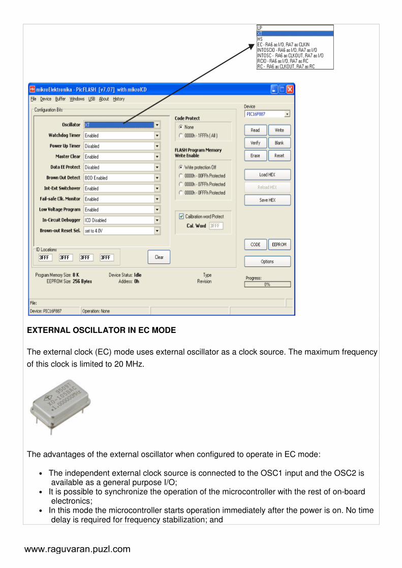
EXTERNAL OSCILLATOR IN EC MODE
The external clock (EC) mode uses external oscillator as a clock source. The maximum frequency
of this clock is limited to 20 MHz.
The advantages of the external oscillator when configured to operate in EC mode:
• The independent external clock source is connected to the OSC1 input and the OSC2 is available as a general purpose I/O;
• It is possible to synchronize the operation of the microcontroller with the rest of on-board electronics;
• In this mode the microcontroller starts operation immediately after the power is on. No time delay is required for frequency stabilization; and
www.raguvaran.puzl.com
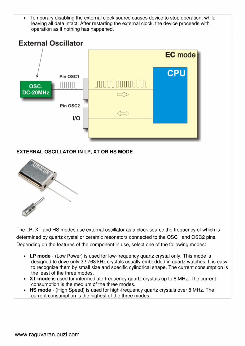
• Temporary disabling the external clock source causes device to stop operation, while leaving all data intact. After restarting the external clock, the device proceeds with operation as if nothing has happened.
EXTERNAL OSCILLATOR IN LP, XT OR HS MODE
The LP, XT and HS modes use external oscillator as a clock source the frequency of which is
determined by quartz crystal or ceramic resonators connected to the OSC1 and OSC2 pins.
Depending on the features of the component in use, select one of the following modes:
• LP mode - (Low Power) is used for low-frequency quartz crystal only. This mode is designed to drive only 32.768 kHz crystals usually embedded in quartz watches. It is easy to recognize them by small size and specific cylindrical shape. The current consumption is the least of the three modes.
• XT mode is used for intermediate-frequency quartz crystals up to 8 MHz. The current consumption is the medium of the three modes.
• HS mode - (High Speed) is used for high-frequency quartz crystals over 8 MHz. The current consumption is the highest of the three modes.
www.raguvaran.puzl.com
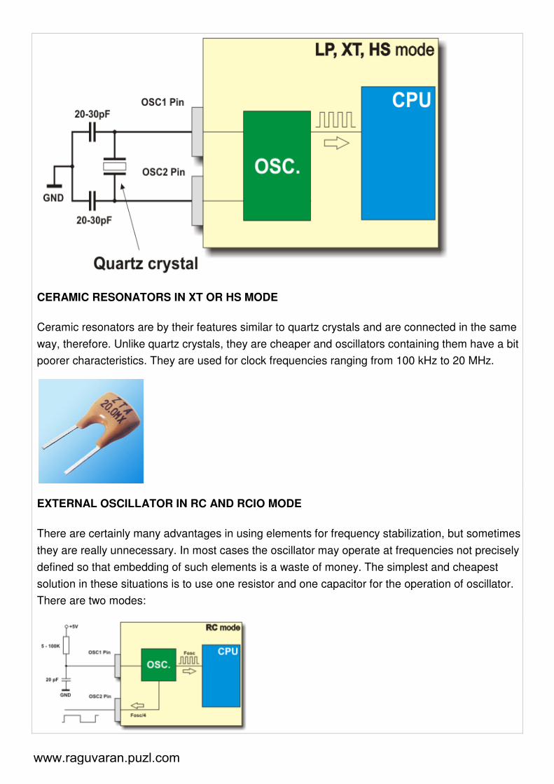
CERAMIC RESONATORS IN XT OR HS MODE
Ceramic resonators are by their features similar to quartz crystals and are connected in the same
way, therefore. Unlike quartz crystals, they are cheaper and oscillators containing them have a bit
poorer characteristics. They are used for clock frequencies ranging from 100 kHz to 20 MHz.
EXTERNAL OSCILLATOR IN RC AND RCIO MODE
There are certainly many advantages in using elements for frequency stabilization, but sometimes
they are really unnecessary. In most cases the oscillator may operate at frequencies not precisely
defined so that embedding of such elements is a waste of money. The simplest and cheapest
solution in these situations is to use one resistor and one capacitor for the operation of oscillator.
There are two modes:
www.raguvaran.puzl.com
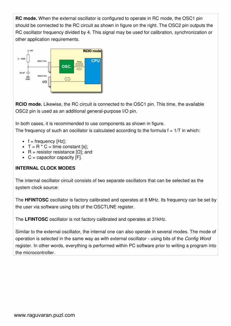
RC mode. When the external oscillator is configured to operate in RC mode, the OSC1 pin
should be connected to the RC circuit as shown in figure on the right. The OSC2 pin outputs the
RC oscillator frequency divided by 4. This signal may be used for calibration, synchronization or
other application requirements.
RCIO mode. Likewise, the RC circuit is connected to the OSC1 pin. This time, the available
OSC2 pin is used as an additional general-purpose I/O pin.
In both cases, it is recommended to use components as shown in figure.
The frequency of such an oscillator is calculated according to the formula f = 1/T in which:
• f = frequency [Hz]; • T = R * C = time constant [s]; • R = resistor resistance [Ω]; and • C = capacitor capacity [F].
INTERNAL CLOCK MODES
The internal oscillator circuit consists of two separate oscillators that can be selected as the
system clock source:
The HFINTOSC oscillator is factory calibrated and operates at 8 MHz. Its frequency can be set by
the user via software using bits of the OSCTUNE register.
The LFINTOSC oscillator is not factory calibrated and operates at 31kHz.
Similar to the external oscillator, the internal one can also operate in several modes. The mode of
operation is selected in the same way as with external oscillator - using bits of the Config Word
register. In other words, everything is performed within PC software prior to writing a program into
the microcontroller.
www.raguvaran.puzl.com
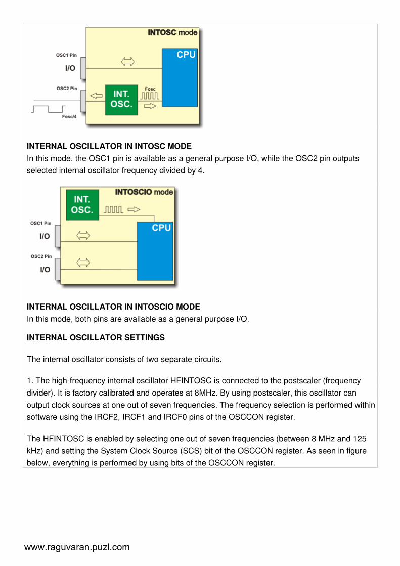
INTERNAL OSCILLATOR IN INTOSC MODE
In this mode, the OSC1 pin is available as a general purpose I/O, while the OSC2 pin outputs
selected internal oscillator frequency divided by 4.
INTERNAL OSCILLATOR IN INTOSCIO MODE
In this mode, both pins are available as a general purpose I/O.
INTERNAL OSCILLATOR SETTINGS
The internal oscillator consists of two separate circuits.
1. The high-frequency internal oscillator HFINTOSC is connected to the postscaler (frequency
divider). It is factory calibrated and operates at 8MHz. By using postscaler, this oscillator can
output clock sources at one out of seven frequencies. The frequency selection is performed within
software using the IRCF2, IRCF1 and IRCF0 pins of the OSCCON register.
The HFINTOSC is enabled by selecting one out of seven frequencies (between 8 MHz and 125
kHz) and setting the System Clock Source (SCS) bit of the OSCCON register. As seen in figure
below, everything is performed by using bits of the OSCCON register.
www.raguvaran.puzl.com
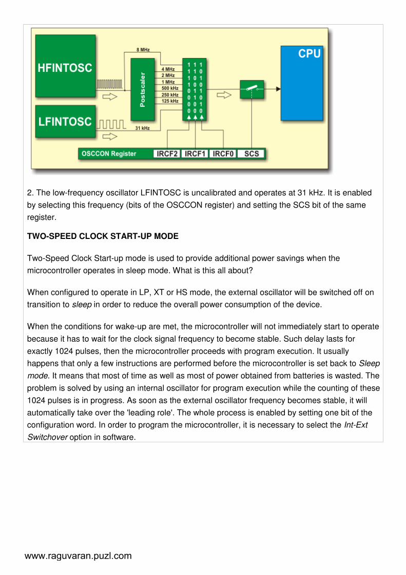
2. The low-frequency oscillator LFINTOSC is uncalibrated and operates at 31 kHz. It is enabled
by selecting this frequency (bits of the OSCCON register) and setting the SCS bit of the same
register.
TWO-SPEED CLOCK START-UP MODE
Two-Speed Clock Start-up mode is used to provide additional power savings when the
microcontroller operates in sleep mode. What is this all about?
When configured to operate in LP, XT or HS mode, the external oscillator will be switched off on
transition to sleep in order to reduce the overall power consumption of the device.
When the conditions for wake-up are met, the microcontroller will not immediately start to operate
because it has to wait for the clock signal frequency to become stable. Such delay lasts for
exactly 1024 pulses, then the microcontroller proceeds with program execution. It usually
happens that only a few instructions are performed before the microcontroller is set back to Sleep
mode. It means that most of time as well as most of power obtained from batteries is wasted. The
problem is solved by using an internal oscillator for program execution while the counting of these
1024 pulses is in progress. As soon as the external oscillator frequency becomes stable, it will
automatically take over the 'leading role'. The whole process is enabled by setting one bit of the
configuration word. In order to program the microcontroller, it is necessary to select the Int-Ext
Switchover option in software.
www.raguvaran.puzl.com
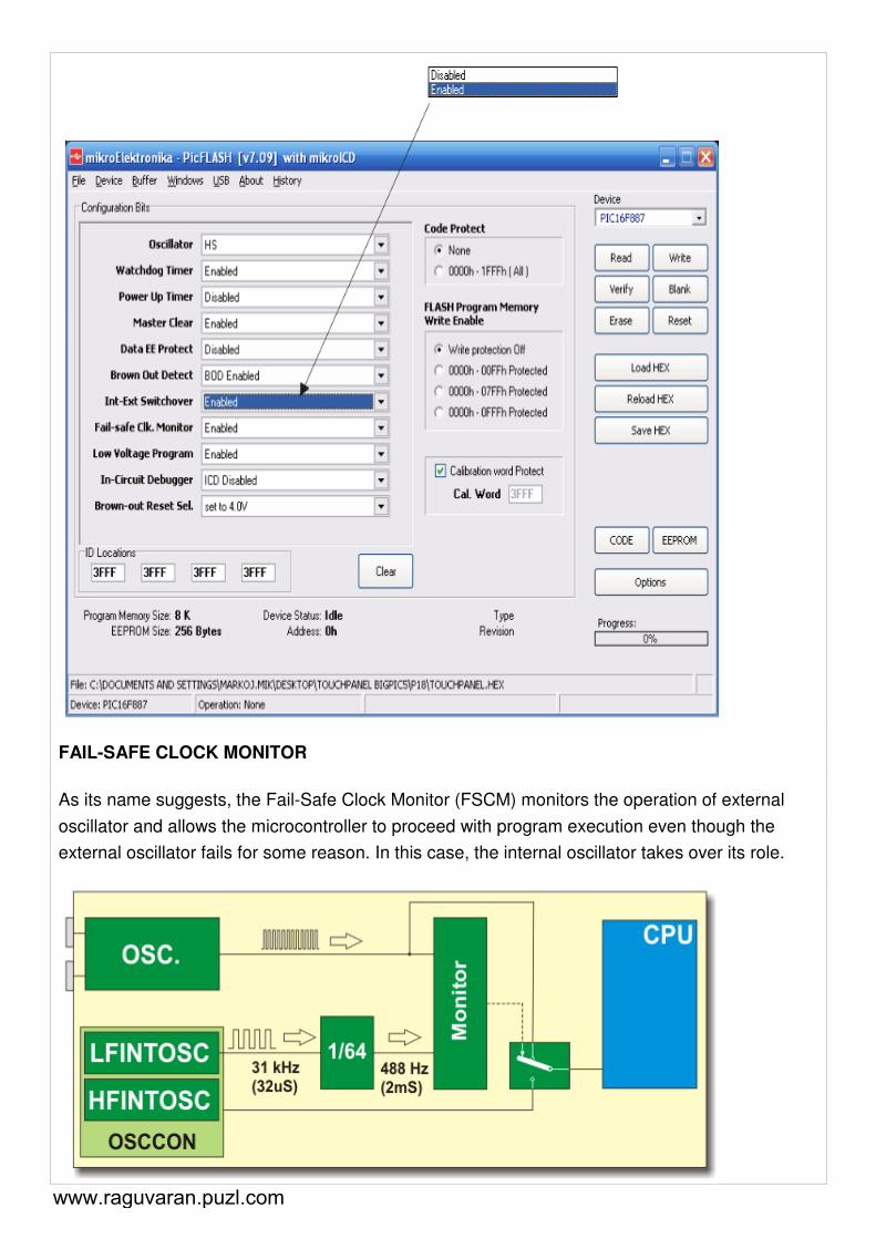
FAIL-SAFE CLOCK MONITOR
As its name suggests, the Fail-Safe Clock Monitor (FSCM) monitors the operation of external
oscillator and allows the microcontroller to proceed with program execution even though the
external oscillator fails for some reason. In this case, the internal oscillator takes over its role.
www.raguvaran.puzl.com
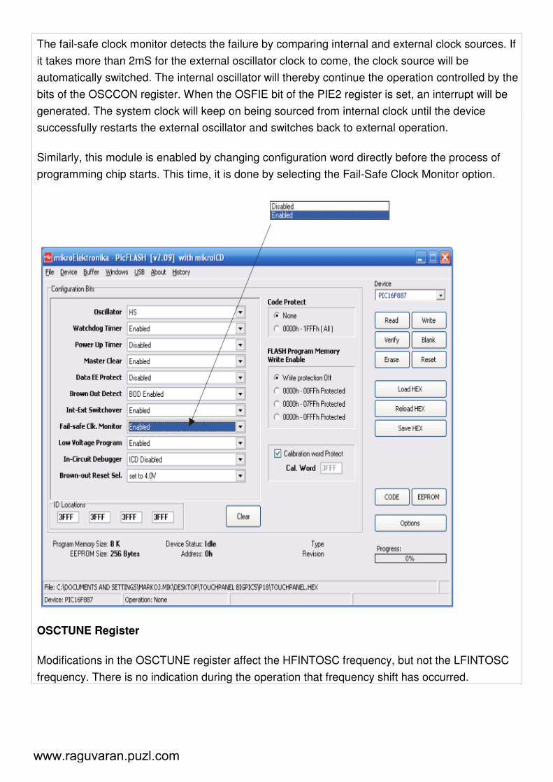
The fail-safe clock monitor detects the failure by comparing internal and external clock sources. If
it takes more than 2mS for the external oscillator clock to come, the clock source will be
automatically switched. The internal oscillator will thereby continue the operation controlled by the
bits of the OSCCON register. When the OSFIE bit of the PIE2 register is set, an interrupt will be
generated. The system clock will keep on being sourced from internal clock until the device
successfully restarts the external oscillator and switches back to external operation.
Similarly, this module is enabled by changing configuration word directly before the process of
programming chip starts. This time, it is done by selecting the Fail-Safe Clock Monitor option.
OSCTUNE Register
Modifications in the OSCTUNE register affect the HFINTOSC frequency, but not the LFINTOSC
frequency. There is no indication during the operation that frequency shift has occurred.
www.raguvaran.puzl.com
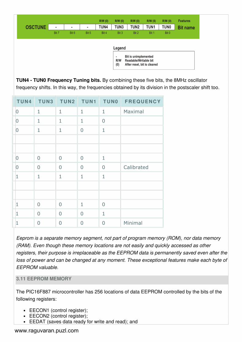
TUN4 - TUN0 Frequency Tuning bits. By combining these five bits, the 8MHz oscillator
frequency shifts. In this way, the frequencies obtained by its division in the postscaler shift too.
TUN4 TUN3 TUN2 TUN1 TUN0 FREQUENCY
0 1 1 1 1 Maximal
0 1 1 1 0
0 1 1 0 1
0 0 0 0 1
0 0 0 0 0 Calibrated
1 1 1 1 1
1 0 0 1 0
1 0 0 0 1
1 0 0 0 0 Minimal
Eeprom is a separate memory segment, not part of program memory (ROM), nor data memory
(RAM). Even though these memory locations are not easily and quickly accessed as other
registers, their purpose is irreplaceable as the EEPROM data is permanently saved even after the
loss of power and can be changed at any moment. These exceptional features make each byte of
EEPROM valuable.
3.11 EEPROM MEMORY
The PIC16F887 microcontroller has 256 locations of data EEPROM controlled by the bits of the
following registers:
• EECON1 (control register); • EECON2 (control register); • EEDAT (saves data ready for write and read); and
www.raguvaran.puzl.com
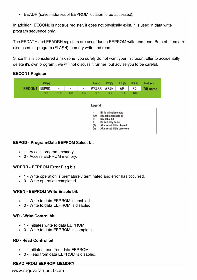
• EEADR (saves address of EEPROM location to be accessed).
In addition, EECON2 is not true register, it does not physically exist. It is used in data write
program sequence only.
The EEDATH and EEADRH registers are used during EEPROM write and read. Both of them are
also used for program (FLASH) memory write and read.
Since this is considered a risk zone (you surely do not want your microcontroller to accidentally
delete it’s own program), we will not discuss it further, but advise you to be careful.
EECON1 Register
EEPGD - Program/Data EEPROM Select bit
• 1 - Access program memory. • 0 - Access EEPROM memory.
WRERR - EEPROM Error Flag bit
• 1 - Write operation is prematurely terminated and error has occurred. • 0 - Write operation completed.
WREN - EEPROM Write Enable bit.
• 1 - Write to data EEPROM is enabled. • 0 - Write to data EEPROM is disabled.
WR - Write Control bit
• 1 - Initiates write to data EEPROM. • 0 - Write to data EEPROM is complete.
RD - Read Control bit
• 1 - Initiates read from data EEPROM. • 0 - Read from data EEPROM is disabled.
READ FROM EEPROM MEMORY
www.raguvaran.puzl.com
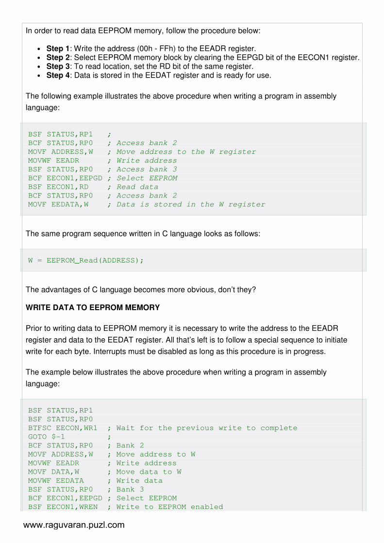
In order to read data EEPROM memory, follow the procedure below:
• Step 1: Write the address (00h - FFh) to the EEADR register. • Step 2: Select EEPROM memory block by clearing the EEPGD bit of the EECON1 register. • Step 3: To read location, set the RD bit of the same register. • Step 4: Data is stored in the EEDAT register and is ready for use.
The following example illustrates the above procedure when writing a program in assembly
language:
BSF STATUS,RP1 ;
BCF STATUS,RP0 ; Access bank 2
MOVF ADDRESS,W ; Move address to the W register
MOVWF EEADR ; Write address
BSF STATUS,RP0 ; Access bank 3
BCF EECON1,EEPGD ; Select EEPROM
BSF EECON1,RD ; Read data
BCF STATUS,RP0 ; Access bank 2
MOVF EEDATA,W ; Data is stored in the W register
The same program sequence written in C language looks as follows:
W = EEPROM_Read(ADDRESS);
The advantages of C language becomes more obvious, don’t they?
WRITE DATA TO EEPROM MEMORY
Prior to writing data to EEPROM memory it is necessary to write the address to the EEADR
register and data to the EEDAT register. All that’s left is to follow a special sequence to initiate
write for each byte. Interrupts must be disabled as long as this procedure is in progress.
The example below illustrates the above procedure when writing a program in assembly
language:
BSF STATUS,RP1
BSF STATUS,RP0
BTFSC EECON,WR1 ; Wait for the previous write to complete
GOTO $-1 ;
BCF STATUS,RP0 ; Bank 2
MOVF ADDRESS,W ; Move address to W
MOVWF EEADR ; Write address
MOVF DATA,W ; Move data to W
MOVWF EEDATA ; Write data
BSF STATUS,RP0 ; Bank 3
BCF EECON1,EEPGD ; Select EEPROM
BSF EECON1,WREN ; Write to EEPROM enabled
www.raguvaran.puzl.com
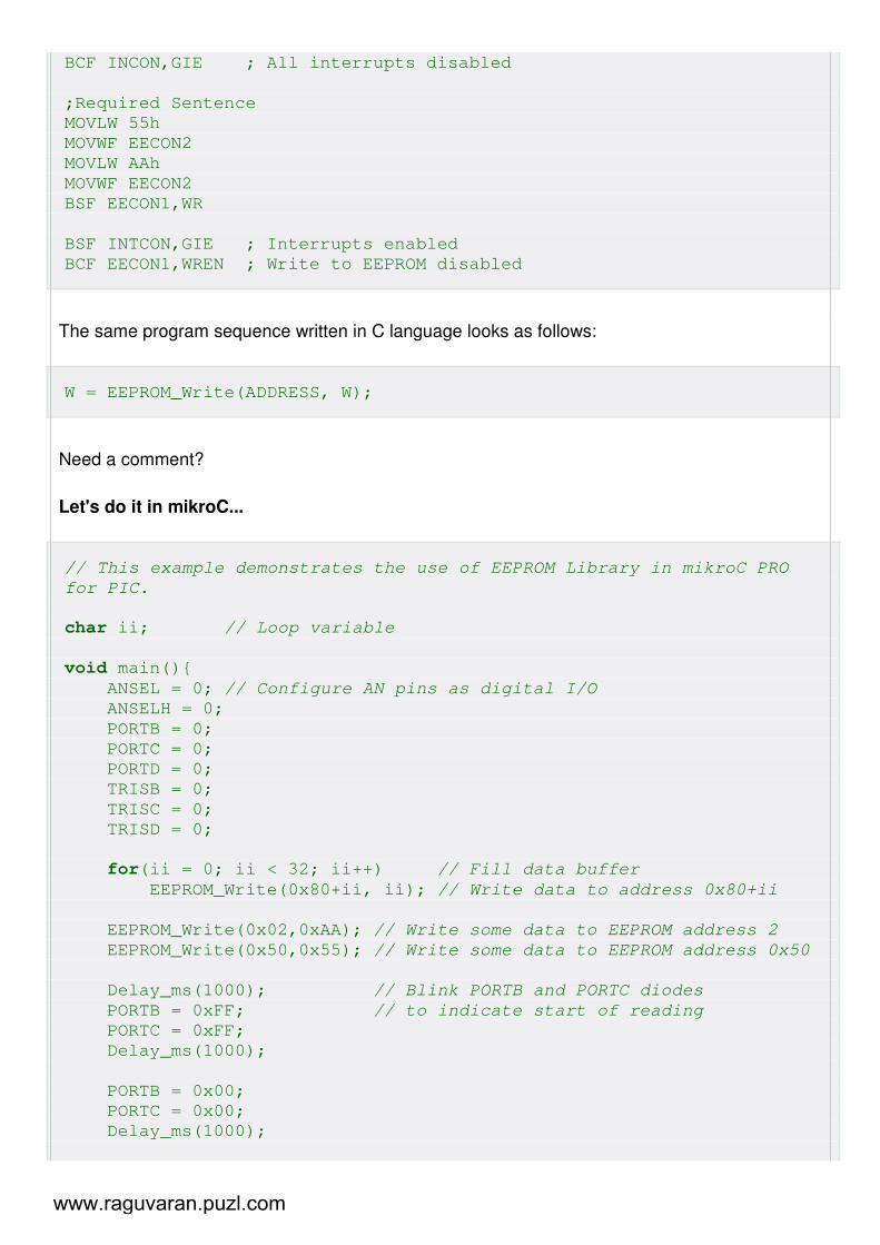
BCF INCON,GIE ; All interrupts disabled
;Required Sentence
MOVLW 55h
MOVWF EECON2
MOVLW AAh
MOVWF EECON2
BSF EECON1,WR
BSF INTCON,GIE ; Interrupts enabled
BCF EECON1,WREN ; Write to EEPROM disabled
The same program sequence written in C language looks as follows:
W = EEPROM_Write(ADDRESS, W);
Need a comment?
Let's do it in mikroC...
// This example demonstrates the use of EEPROM Library in mikroC PRO
for PIC.
char ii; // Loop variable
void main()
ANSEL = 0; // Configure AN pins as digital I/O
ANSELH = 0;
PORTB = 0;
PORTC = 0;
PORTD = 0;
TRISB = 0;
TRISC = 0;
TRISD = 0;
for(ii = 0; ii < 32; ii++) // Fill data buffer
EEPROM_Write(0x80+ii, ii); // Write data to address 0x80+ii
EEPROM_Write(0x02,0xAA); // Write some data to EEPROM address 2
EEPROM_Write(0x50,0x55); // Write some data to EEPROM address 0x50
Delay_ms(1000); // Blink PORTB and PORTC diodes
PORTB = 0xFF; // to indicate start of reading
PORTC = 0xFF;
Delay_ms(1000);
PORTB = 0x00;
PORTC = 0x00;
Delay_ms(1000);
www.raguvaran.puzl.com

PORTB = EEPROM_Read(0x02); // Read data from EEPROM address 2 and
display it on PORTB
PORTC = EEPROM_Read(0x50); // Read data from EEPROM address 0x50
and display it on PORTC
Delay_ms(1000);
for(ii = 0; ii < 32; ii++) // Read 32 bytes block from
address 0x80
PORTD = EEPROM_Read(0x80+ii); // and display data on PORTD
Delay_ms(250);
At first glance, it is sufficient to turn the power on to make the microcontroller operate. At first
glance, it is sufficient to turn the power off to make it stop operating. Only at first glance... In
reality, start and end of operation are critical phases of which a special signal called RESET takes
care.
3.12 RESET! BLACK-OUT, BROWN-OUT OR NOISES?
Reset condition causes the microcontroller to immediately stop operation and clear its registers.
Areset signal may be generated externally at any moment (low logic level on the MCLR pin). If
needed, it can also be generated by internal control logic. Power-on always causes reset. Since
there are many transitional events taking place when power supply is turned on (switch contact
flashing and sparkling, slow voltage rise, gradual clock frequency stabilization etc.), it is
necessary to provide a certain time delay for the microcontroller before it starts to operate. Two
internal timers- PWRT and OST are in charge of that. The first one can be enabled or disabled
during the process of writing a program. Let’s take a look what happens then:
When the power supply voltage reaches 1.2 - 1.7V, a circuit called Power-up timer resets the
microcontroller within approximately 72mS. As soon as this time expires, another timer called
Oscillator start-up timer generates another reset signal within 1024 quartz oscillator periods.
When this delay expires (marked as T reset in figure) and the MCLR pin is set high, all conditions
are met and the microcontroller starts to execute the first instruction in the program.
www.raguvaran.puzl.com
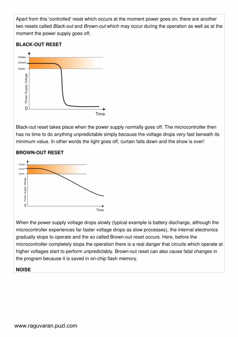
Apart from this 'controlled' reset which occurs at the moment power goes on, there are another
two resets called Black-out and Brown-out which may occur during the operation as well as at the
moment the power supply goes off.
BLACK-OUT RESET
Black-out reset takes place when the power supply normally goes off. The microcontroller then
has no time to do anything unpredictable simply because the voltage drops very fast beneath its
minimum value. In other words the light goes off, curtain falls down and the show is over!
BROWN-OUT RESET
When the power supply voltage drops slowly (typical example is battery discharge, although the
microcontroller experiences far faster voltage drops as slow processes), the internal electronics
gradually stops to operate and the so called Brown-out reset occurs. Here, before the
microcontroller completely stops the operation there is a real danger that circuits which operate at
higher voltages start to perform unpredictably. Brown-out reset can also cause fatal changes in
the program because it is saved in on-chip flash memory.
NOISE
www.raguvaran.puzl.com
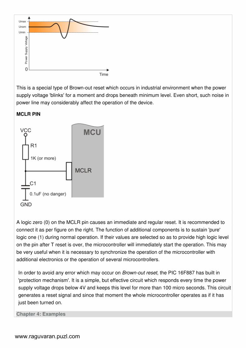
This is a special type of Brown-out reset which occurs in industrial environment when the power
supply voltage 'blinks' for a moment and drops beneath minimum level. Even short, such noise in
power line may considerably affect the operation of the device.
MCLR PIN
A logic zero (0) on the MCLR pin causes an immediate and regular reset. It is recommended to
connect it as per figure on the right. The function of additional components is to sustain 'pure'
logic one (1) during normal operation. If their values are selected so as to provide high logic level
on the pin after T reset is over, the microcontroller will immediately start the operation. This may
be very useful when it is necessary to synchronize the operation of the microcontroller with
additional electronics or the operation of several microcontrollers.
In order to avoid any error which may occur on Brown-out reset, the PIC 16F887 has built in
'protection mechanism'. It is a simple, but effective circuit which responds every time the power
supply voltage drops below 4V and keeps this level for more than 100 micro seconds. This circuit
generates a reset signal and since that moment the whole microcontroller operates as if it has
just been turned on.
Chapter 4: Examples
www.raguvaran.puzl.com
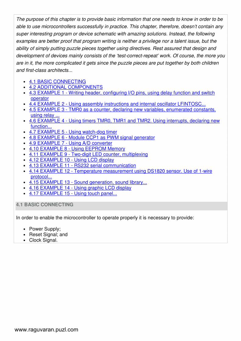
The purpose of this chapter is to provide basic information that one needs to know in order to be
able to use microcontrollers successfully in practice. This chapter, therefore, doesn’t contain any
super interesting program or device schematic with amazing solutions. Instead, the following
examples are better proof that program writing is neither a privilege nor a talent issue, but the
ability of simply putting puzzle pieces together using directives. Rest assured that design and
development of devices mainly consists of the ‘test-correct-repeat’ work. Of course, the more you
are in it, the more complicated it gets since the puzzle pieces are put together by both children
and first-class architects...
• 4.1 BASIC CONNECTING • 4.2 ADDITIONAL COMPONENTS • 4.3 EXAMPLE 1 - Writing header, configuring I/O pins, using delay function and switch
operator • 4.4 EXAMPLE 2 - Using assembly instructions and internal oscillator LFINTOSC... • 4.5 EXAMPLE 3 - TMR0 as a counter, declaring new variables, enumerated constants,
using relay ... • 4.6 EXAMPLE 4 - Using timers TMR0, TMR1 and TMR2. Using interrupts, declaring new
function... • 4.7 EXAMPLE 5 - Using watch-dog timer • 4.8 EXAMPLE 6 - Module CCP1 as PWM signal generator • 4.9 EXAMPLE 7 - Using A/D converter • 4.10 EXAMPLE 8 - Using EEPROM Memory • 4.11 EXAMPLE 9 - Two-digit LED counter, multiplexing • 4.12 EXAMPLE 10 - Using LCD display • 4.13 EXAMPLE 11 - RS232 serial communication • 4.14 EXAMPLE 12 - Temperature measurement using DS1820 sensor. Use of 1-wire
protocol... • 4.15 EXAMPLE 13 - Sound generation, sound library... • 4.16 EXAMPLE 14 - Using graphic LCD display • 4.17 EXAMPLE 15 - Using touch panel...
4.1 BASIC CONNECTING
In order to enable the microcontroller to operate properly it is necessary to provide:
• Power Supply; • Reset Signal; and • Clock Signal.
www.raguvaran.puzl.com
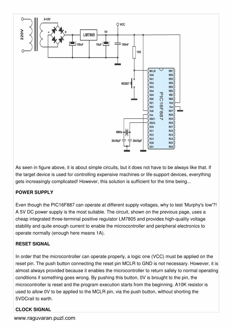
As seen in figure above, it is about simple circuits, but it does not have to be always like that. If
the target device is used for controlling expensive machines or life-support devices, everything
gets increasingly complicated! However, this solution is sufficient for the time being...
POWER SUPPLY
Even though the PIC16F887 can operate at different supply voltages, why to test 'Murphy's low'?!
A 5V DC power supply is the most suitable. The circuit, shown on the previous page, uses a
cheap integrated three-terminal positive regulator LM7805 and provides high-quality voltage
stability and quite enough current to enable the microcontroller and peripheral electronics to
operate normally (enough here means 1A).
RESET SIGNAL
In order that the microcontroller can operate properly, a logic one (VCC) must be applied on the
reset pin. The push button connecting the reset pin MCLR to GND is not necessary. However, it is
almost always provided because it enables the microcontroller to return safely to normal operating
conditions if something goes wrong. By pushing this button, 0V is brought to the pin, the
microcontroller is reset and the program execution starts from the beginning. A10K resistor is
used to allow 0V to be applied to the MCLR pin, via the push button, without shorting the
5VDCrail to earth.
CLOCK SIGNAL
www.raguvaran.puzl.com
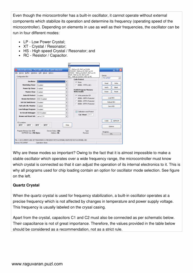
Even though the microcontroller has a built-in oscillator, it cannot operate without external
components which stabilize its operation and determine its frequency (operating speed of the
microcontroller). Depending on elements in use as well as their frequencies, the oscillator can be
run in four different modes:
• LP - Low Power Crystal; • XT - Crystal / Resonator; • HS - High speed Crystal / Resonator; and • RC - Resistor / Capacitor.
Why are these modes so important? Owing to the fact that it is almost impossible to make a
stable oscillator which operates over a wide frequency range, the microcontroller must know
which crystal is connected so that it can adjust the operation of its internal electronics to it. This is
why all programs used for chip loading contain an option for oscillator mode selection. See figure
on the left.
Quartz Crystal
When the quartz crystal is used for frequency stabilization, a built-in oscillator operates at a
precise frequency which is not affected by changes in temperature and power supply voltage.
This frequency is usually labeled on the crysal casing.
Apart from the crystal, capacitors C1 and C2 must also be connected as per schematic below.
Their capacitance is not of great importance. Therefore, the values provided in the table below
should be considered as a recommendation, not as a strict rule.
www.raguvaran.puzl.com
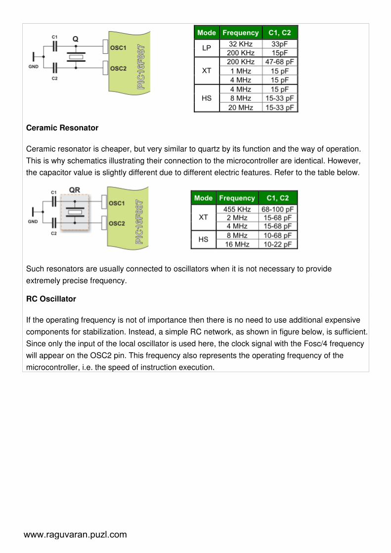
Ceramic Resonator
Ceramic resonator is cheaper, but very similar to quartz by its function and the way of operation.
This is why schematics illustrating their connection to the microcontroller are identical. However,
the capacitor value is slightly different due to different electric features. Refer to the table below.
Such resonators are usually connected to oscillators when it is not necessary to provide
extremely precise frequency.
RC Oscillator
If the operating frequency is not of importance then there is no need to use additional expensive
components for stabilization. Instead, a simple RC network, as shown in figure below, is sufficient.
Since only the input of the local oscillator is used here, the clock signal with the Fosc/4 frequency
will appear on the OSC2 pin. This frequency also represents the operating frequency of the
microcontroller, i.e. the speed of instruction execution.
www.raguvaran.puzl.com
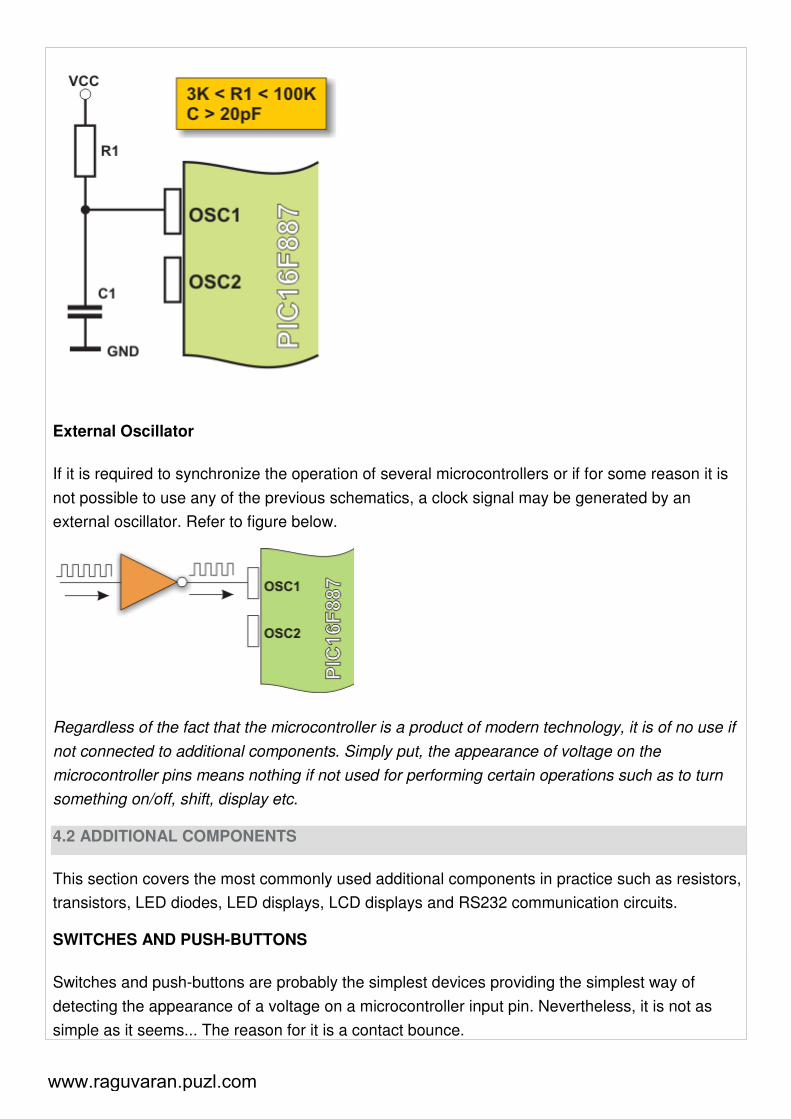
External Oscillator
If it is required to synchronize the operation of several microcontrollers or if for some reason it is
not possible to use any of the previous schematics, a clock signal may be generated by an
external oscillator. Refer to figure below.
Regardless of the fact that the microcontroller is a product of modern technology, it is of no use if
not connected to additional components. Simply put, the appearance of voltage on the
microcontroller pins means nothing if not used for performing certain operations such as to turn
something on/off, shift, display etc.
4.2 ADDITIONAL COMPONENTS
This section covers the most commonly used additional components in practice such as resistors,
transistors, LED diodes, LED displays, LCD displays and RS232 communication circuits.
SWITCHES AND PUSH-BUTTONS
Switches and push-buttons are probably the simplest devices providing the simplest way of
detecting the appearance of a voltage on a microcontroller input pin. Nevertheless, it is not as
simple as it seems... The reason for it is a contact bounce.
www.raguvaran.puzl.com
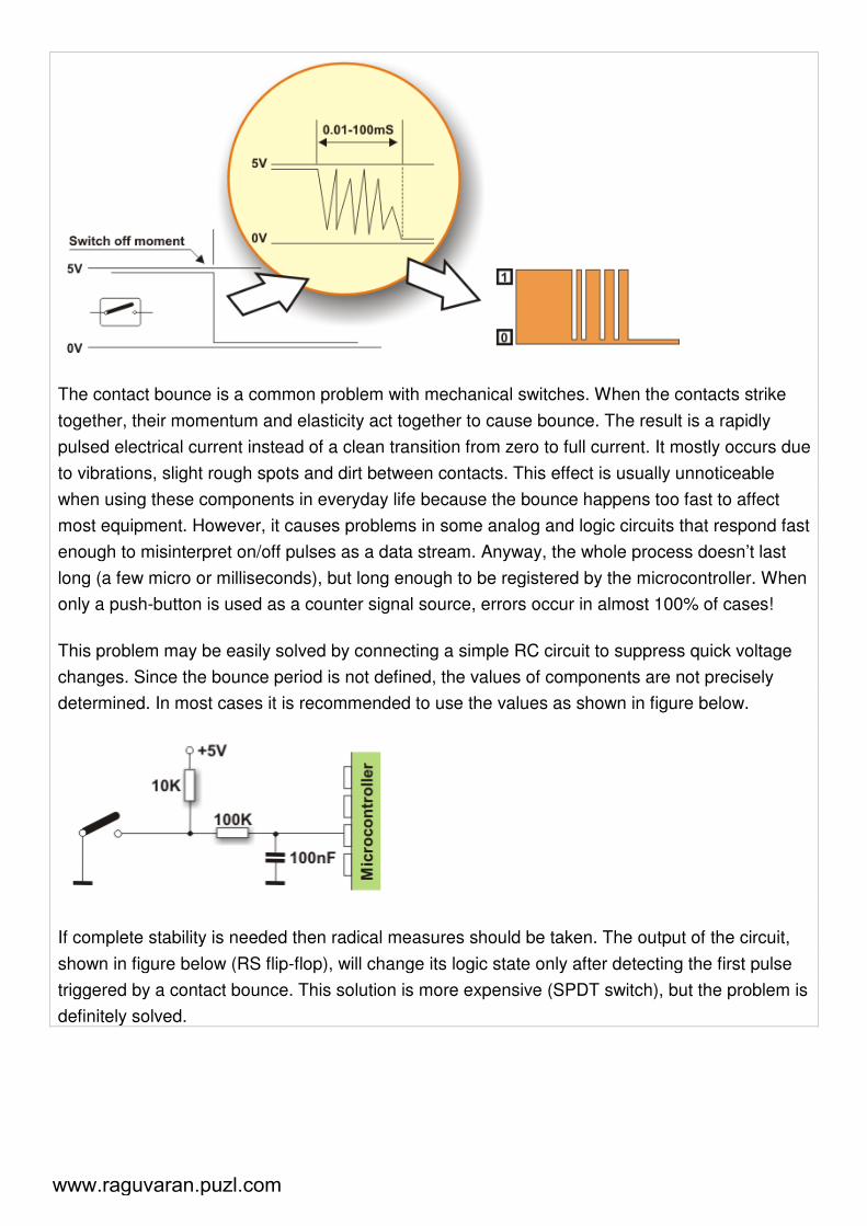
The contact bounce is a common problem with mechanical switches. When the contacts strike
together, their momentum and elasticity act together to cause bounce. The result is a rapidly
pulsed electrical current instead of a clean transition from zero to full current. It mostly occurs due
to vibrations, slight rough spots and dirt between contacts. This effect is usually unnoticeable
when using these components in everyday life because the bounce happens too fast to affect
most equipment. However, it causes problems in some analog and logic circuits that respond fast
enough to misinterpret on/off pulses as a data stream. Anyway, the whole process doesn’t last
long (a few micro or milliseconds), but long enough to be registered by the microcontroller. When
only a push-button is used as a counter signal source, errors occur in almost 100% of cases!
This problem may be easily solved by connecting a simple RC circuit to suppress quick voltage
changes. Since the bounce period is not defined, the values of components are not precisely
determined. In most cases it is recommended to use the values as shown in figure below.
If complete stability is needed then radical measures should be taken. The output of the circuit,
shown in figure below (RS flip-flop), will change its logic state only after detecting the first pulse
triggered by a contact bounce. This solution is more expensive (SPDT switch), but the problem is
definitely solved.
www.raguvaran.puzl.com
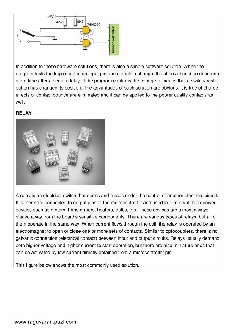
In addition to these hardware solutions, there is also a simple software solution. When the
program tests the logic state of an input pin and detects a change, the check should be done one
more time after a certain delay. If the program confirms the change, it means that a switch/push
button has changed its position. The advantages of such solution are obvious: it is free of charge,
effects of contact bounce are eliminated and it can be applied to the poorer quality contacts as
well.
RELAY
A relay is an electrical switch that opens and closes under the control of another electrical circuit.
It is therefore connected to output pins of the microcontroller and used to turn on/off high-power
devices such as motors, transformers, heaters, bulbs, etc. These devices are almost always
placed away from the board’s sensitive components. There are various types of relays, but all of
them operate in the same way. When current flows through the coil, the relay is operated by an
electromagnet to open or close one or more sets of contacts. Similar to optocouplers, there is no
galvanic connection (electrical contact) between input and output circuits. Relays usually demand
both higher voltage and higher current to start operation, but there are also miniature ones that
can be activated by low current directly obtained from a microcontroller pin.
This figure below shows the most commonly used solution.
www.raguvaran.puzl.com
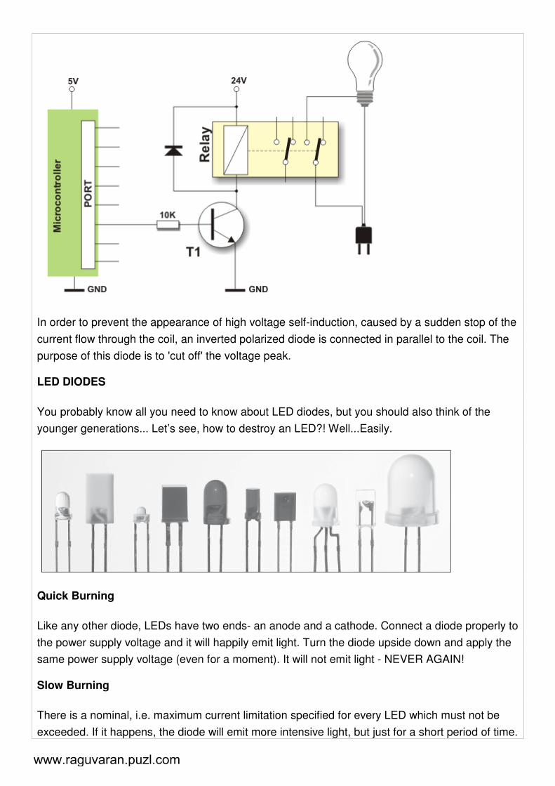
In order to prevent the appearance of high voltage self-induction, caused by a sudden stop of the
current flow through the coil, an inverted polarized diode is connected in parallel to the coil. The
purpose of this diode is to 'cut off' the voltage peak.
LED DIODES
You probably know all you need to know about LED diodes, but you should also think of the
younger generations... Let’s see, how to destroy an LED?! Well...Easily.
Quick Burning
Like any other diode, LEDs have two ends- an anode and a cathode. Connect a diode properly to
the power supply voltage and it will happily emit light. Turn the diode upside down and apply the
same power supply voltage (even for a moment). It will not emit light - NEVER AGAIN!
Slow Burning
There is a nominal, i.e. maximum current limitation specified for every LED which must not be
exceeded. If it happens, the diode will emit more intensive light, but just for a short period of time.
www.raguvaran.puzl.com
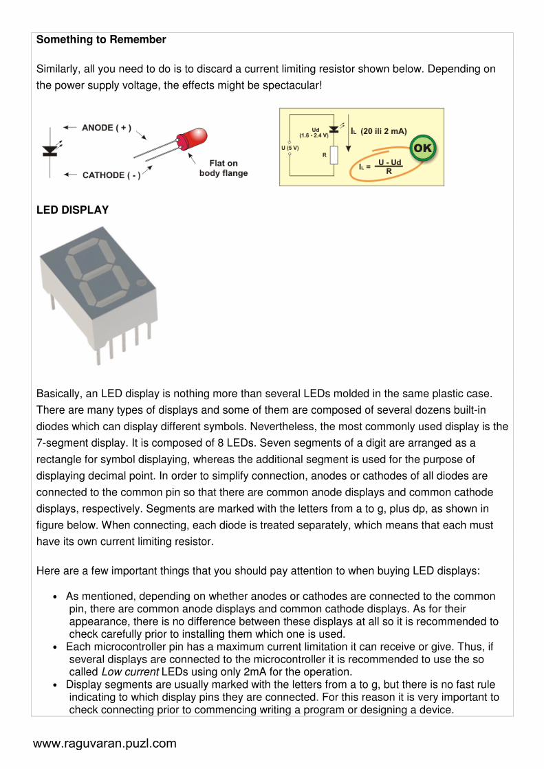
Something to Remember
Similarly, all you need to do is to discard a current limiting resistor shown below. Depending on
the power supply voltage, the effects might be spectacular!
LED DISPLAY
Basically, an LED display is nothing more than several LEDs molded in the same plastic case.
There are many types of displays and some of them are composed of several dozens built-in
diodes which can display different symbols. Nevertheless, the most commonly used display is the
7-segment display. It is composed of 8 LEDs. Seven segments of a digit are arranged as a
rectangle for symbol displaying, whereas the additional segment is used for the purpose of
displaying decimal point. In order to simplify connection, anodes or cathodes of all diodes are
connected to the common pin so that there are common anode displays and common cathode
displays, respectively. Segments are marked with the letters from a to g, plus dp, as shown in
figure below. When connecting, each diode is treated separately, which means that each must
have its own current limiting resistor.
Here are a few important things that you should pay attention to when buying LED displays:
• As mentioned, depending on whether anodes or cathodes are connected to the common pin, there are common anode displays and common cathode displays. As for their appearance, there is no difference between these displays at all so it is recommended to check carefully prior to installing them which one is used.
• Each microcontroller pin has a maximum current limitation it can receive or give. Thus, if several displays are connected to the microcontroller it is recommended to use the so called Low current LEDs using only 2mA for the operation.
• Display segments are usually marked with the letters from a to g, but there is no fast rule indicating to which display pins they are connected. For this reason it is very important to check connecting prior to commencing writing a program or designing a device.
www.raguvaran.puzl.com
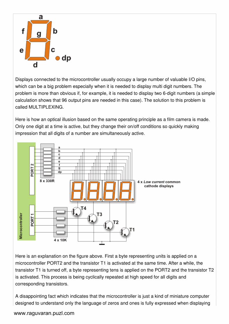
Displays connected to the microcontroller usually occupy a large number of valuable I/O pins,
which can be a big problem especially when it is needed to display multi digit numbers. The
problem is more than obvious if, for example, it is needed to display two 6-digit numbers (a simple
calculation shows that 96 output pins are needed in this case). The solution to this problem is
called MULTIPLEXING.
Here is how an optical illusion based on the same operating principle as a film camera is made.
Only one digit at a time is active, but they change their on/off conditions so quickly making
impression that all digits of a number are simultaneously active.
Here is an explanation on the figure above. First a byte representing units is applied on a
microcontroller PORT2 and the transistor T1 is activated at the same time. After a while, the
transistor T1 is turned off, a byte representing tens is applied on the PORT2 and the transistor T2
is activated. This process is being cyclically repeated at high speed for all digits and
corresponding transistors.
A disappointing fact which indicates that the microcontroller is just a kind of miniature computer
designed to understand only the language of zeros and ones is fully expressed when displaying
www.raguvaran.puzl.com
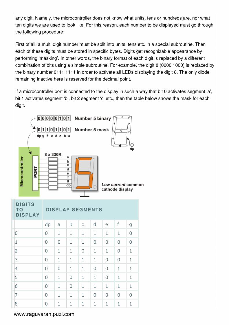
any digit. Namely, the microcontroller does not know what units, tens or hundreds are, nor what
ten digits we are used to look like. For this reason, each number to be displayed must go through
the following procedure:
First of all, a multi digit number must be split into units, tens etc. in a special subroutine. Then
each of these digits must be stored in specific bytes. Digits get recognizable appearance by
performing ‘masking’. In other words, the binary format of each digit is replaced by a different
combination of bits using a simple subroutine. For example, the digit 8 (0000 1000) is replaced by
the binary number 0111 1111 in order to activate all LEDs displaying the digit 8. The only diode
remaining inactive here is reserved for the decimal point.
If a microcontroller port is connected to the display in such a way that bit 0 activates segment ‘a’,
bit 1 activates segment ‘b’, bit 2 segment ‘c’ etc., then the table below shows the mask for each
digit.
DIGITS TO DISPL AY
DISPL AY SEGMENTS
dp a b c d e f g
0 0 1 1 1 1 1 1 0
1 0 0 1 1 0 0 0 0
2 0 1 1 0 1 1 0 1
3 0 1 1 1 1 0 0 1
4 0 0 1 1 0 0 1 1
5 0 1 0 1 1 0 1 1
6 0 1 0 1 1 1 1 1
7 0 1 1 1 0 0 0 0
8 0 1 1 1 1 1 1 1
www.raguvaran.puzl.com
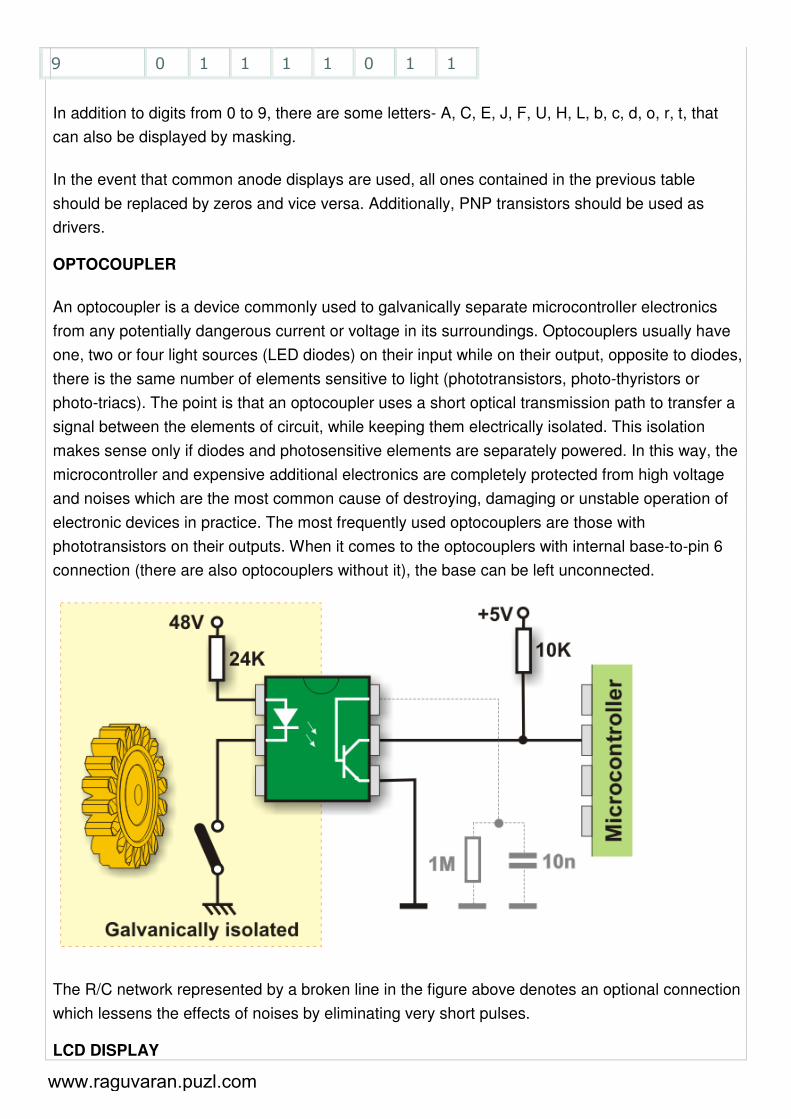
9 0 1 1 1 1 0 1 1
In addition to digits from 0 to 9, there are some letters- A, C, E, J, F, U, H, L, b, c, d, o, r, t, that
can also be displayed by masking.
In the event that common anode displays are used, all ones contained in the previous table
should be replaced by zeros and vice versa. Additionally, PNP transistors should be used as
drivers.
OPTOCOUPLER
An optocoupler is a device commonly used to galvanically separate microcontroller electronics
from any potentially dangerous current or voltage in its surroundings. Optocouplers usually have
one, two or four light sources (LED diodes) on their input while on their output, opposite to diodes,
there is the same number of elements sensitive to light (phototransistors, photo-thyristors or
photo-triacs). The point is that an optocoupler uses a short optical transmission path to transfer a
signal between the elements of circuit, while keeping them electrically isolated. This isolation
makes sense only if diodes and photosensitive elements are separately powered. In this way, the
microcontroller and expensive additional electronics are completely protected from high voltage
and noises which are the most common cause of destroying, damaging or unstable operation of
electronic devices in practice. The most frequently used optocouplers are those with
phototransistors on their outputs. When it comes to the optocouplers with internal base-to-pin 6
connection (there are also optocouplers without it), the base can be left unconnected.
The R/C network represented by a broken line in the figure above denotes an optional connection
which lessens the effects of noises by eliminating very short pulses.
LCD DISPLAY
www.raguvaran.puzl.com
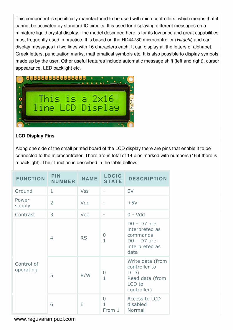
This component is specifically manufactured to be used with microcontrollers, which means that it
cannot be activated by standard IC circuits. It is used for displaying different messages on a
miniature liquid crystal display. The model described here is for its low price and great capabilities
most frequently used in practice. It is based on the HD44780 microcontroller (Hitachi) and can
display messages in two lines with 16 characters each. It can display all the letters of alphabet,
Greek letters, punctuation marks, mathematical symbols etc. It is also possible to display symbols
made up by the user. Other useful features include automatic message shift (left and right), cursor
appearance, LED backlight etc.
LCD Display Pins
Along one side of the small printed board of the LCD display there are pins that enable it to be
connected to the microcontroller. There are in total of 14 pins marked with numbers (16 if there is
a backlight). Their function is described in the table bellow:
FUNCTION PIN NUMBER
NAME LOGIC ST ATE
DESCRIPTION
Ground 1 Vss - 0V
Power supply
2 Vdd - +5V
Contrast 3 Vee - 0 - Vdd
Control of
operating
4 RS 0 1
D0 – D7 are interpreted as
commands D0 – D7 are
interpreted as data
5 R/W 0 1
Write data (from controller to
LCD) Read data (from
LCD to controller)
6 E 0 1
From 1
Access to LCD disabled
Normal
www.raguvaran.puzl.com
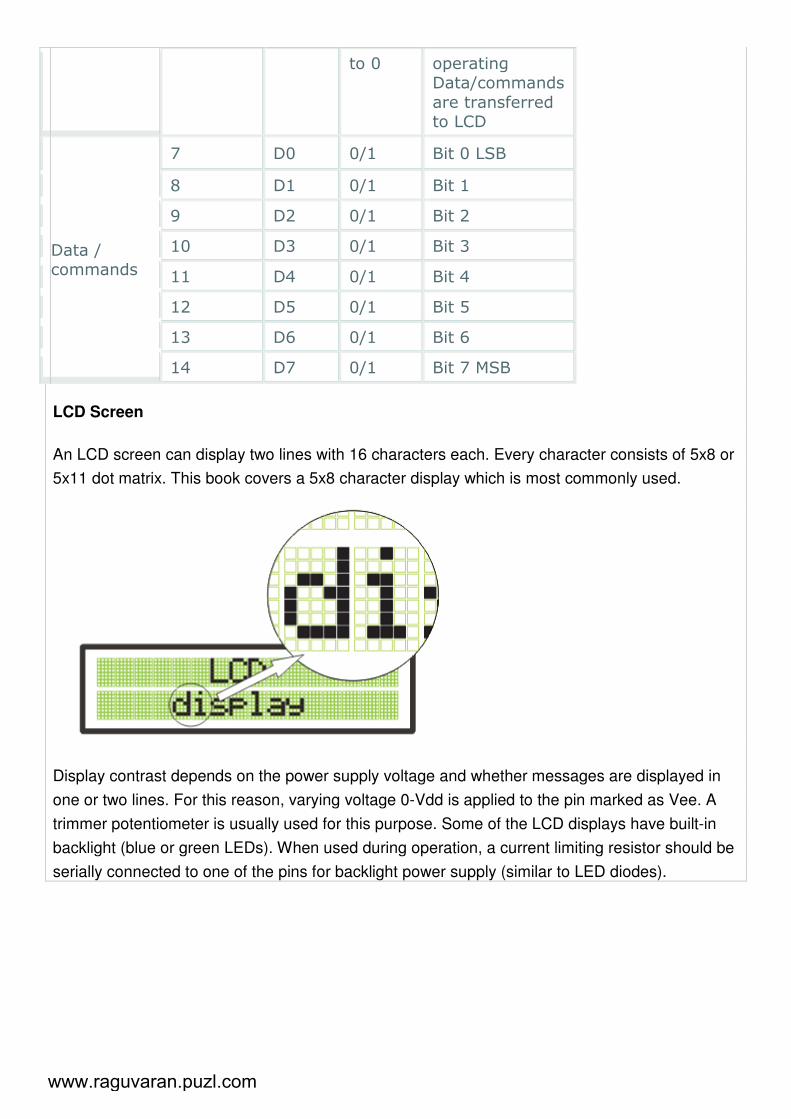
to 0 operating Data/commands
are transferred to LCD
Data / commands
7 D0 0/1 Bit 0 LSB
8 D1 0/1 Bit 1
9 D2 0/1 Bit 2
10 D3 0/1 Bit 3
11 D4 0/1 Bit 4
12 D5 0/1 Bit 5
13 D6 0/1 Bit 6
14 D7 0/1 Bit 7 MSB
LCD Screen
An LCD screen can display two lines with 16 characters each. Every character consists of 5x8 or
5x11 dot matrix. This book covers a 5x8 character display which is most commonly used.
Display contrast depends on the power supply voltage and whether messages are displayed in
one or two lines. For this reason, varying voltage 0-Vdd is applied to the pin marked as Vee. A
trimmer potentiometer is usually used for this purpose. Some of the LCD displays have built-in
backlight (blue or green LEDs). When used during operation, a current limiting resistor should be
serially connected to one of the pins for backlight power supply (similar to LED diodes).
www.raguvaran.puzl.com
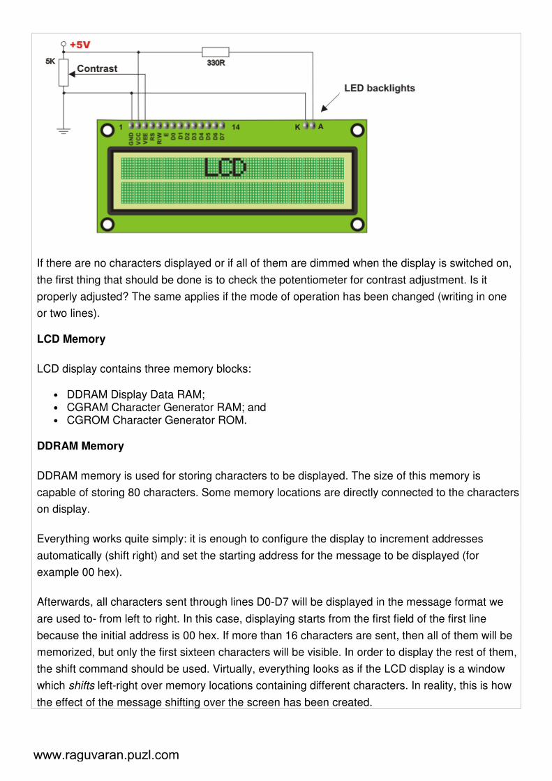
If there are no characters displayed or if all of them are dimmed when the display is switched on,
the first thing that should be done is to check the potentiometer for contrast adjustment. Is it
properly adjusted? The same applies if the mode of operation has been changed (writing in one
or two lines).
LCD Memory
LCD display contains three memory blocks:
• DDRAM Display Data RAM; • CGRAM Character Generator RAM; and • CGROM Character Generator ROM.
DDRAM Memory
DDRAM memory is used for storing characters to be displayed. The size of this memory is
capable of storing 80 characters. Some memory locations are directly connected to the characters
on display.
Everything works quite simply: it is enough to configure the display to increment addresses
automatically (shift right) and set the starting address for the message to be displayed (for
example 00 hex).
Afterwards, all characters sent through lines D0-D7 will be displayed in the message format we
are used to- from left to right. In this case, displaying starts from the first field of the first line
because the initial address is 00 hex. If more than 16 characters are sent, then all of them will be
memorized, but only the first sixteen characters will be visible. In order to display the rest of them,
the shift command should be used. Virtually, everything looks as if the LCD display is a window
which shifts left-right over memory locations containing different characters. In reality, this is how
the effect of the message shifting over the screen has been created.
www.raguvaran.puzl.com
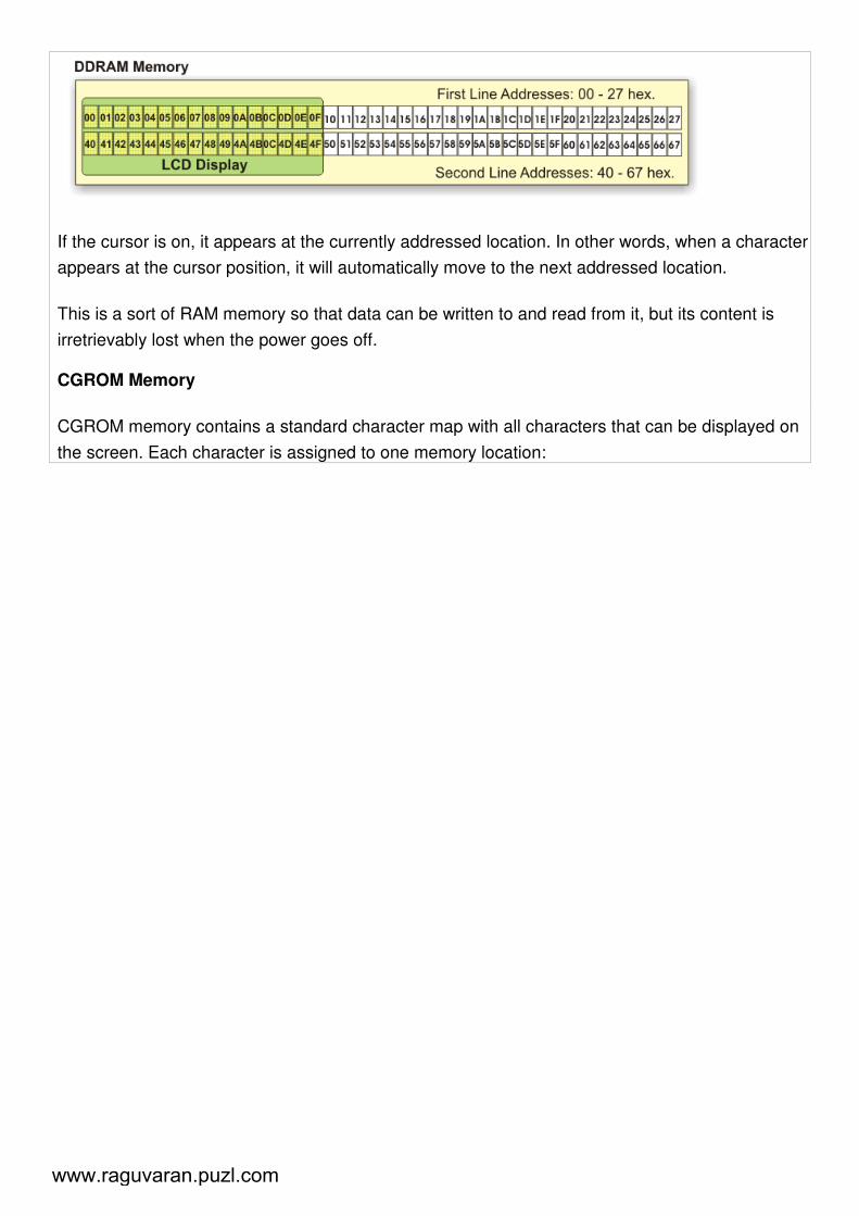
If the cursor is on, it appears at the currently addressed location. In other words, when a character
appears at the cursor position, it will automatically move to the next addressed location.
This is a sort of RAM memory so that data can be written to and read from it, but its content is
irretrievably lost when the power goes off.
CGROM Memory
CGROM memory contains a standard character map with all characters that can be displayed on
the screen. Each character is assigned to one memory location:
www.raguvaran.puzl.com
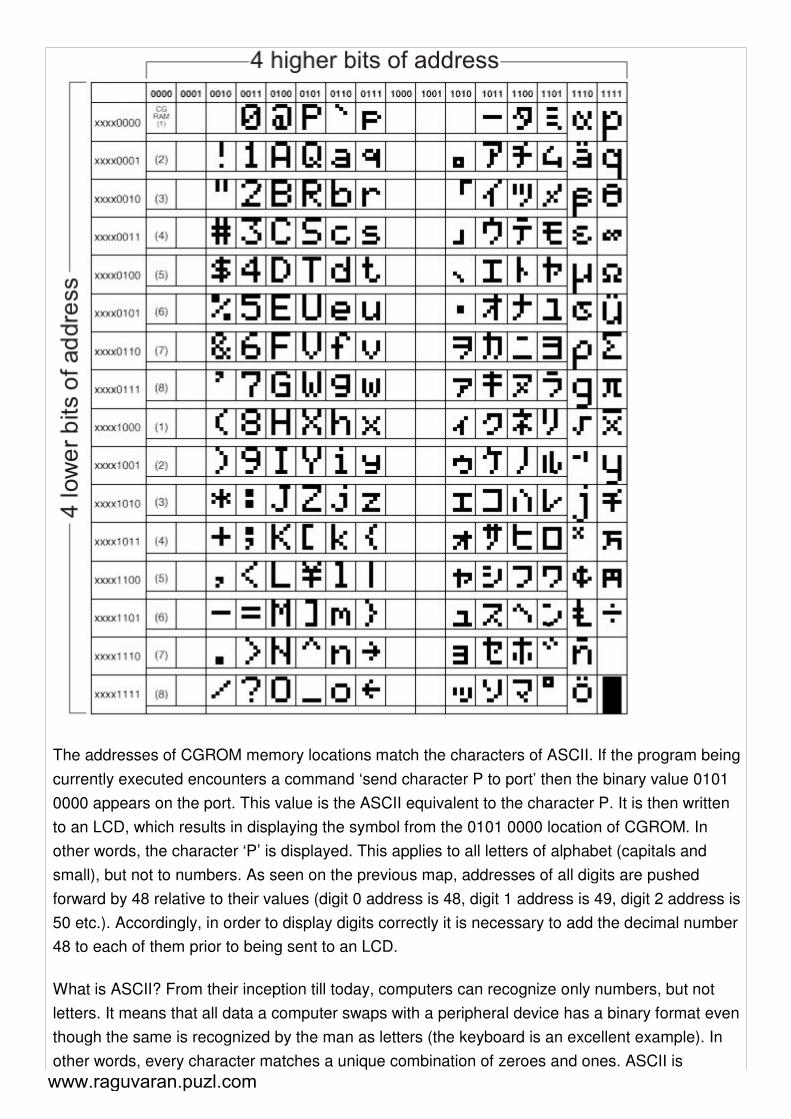
The addresses of CGROM memory locations match the characters of ASCII. If the program being
currently executed encounters a command ‘send character P to port’ then the binary value 0101
0000 appears on the port. This value is the ASCII equivalent to the character P. It is then written
to an LCD, which results in displaying the symbol from the 0101 0000 location of CGROM. In
other words, the character ‘P’ is displayed. This applies to all letters of alphabet (capitals and
small), but not to numbers. As seen on the previous map, addresses of all digits are pushed
forward by 48 relative to their values (digit 0 address is 48, digit 1 address is 49, digit 2 address is
50 etc.). Accordingly, in order to display digits correctly it is necessary to add the decimal number
48 to each of them prior to being sent to an LCD.
What is ASCII? From their inception till today, computers can recognize only numbers, but not
letters. It means that all data a computer swaps with a peripheral device has a binary format even
though the same is recognized by the man as letters (the keyboard is an excellent example). In
other words, every character matches a unique combination of zeroes and ones. ASCII is
www.raguvaran.puzl.com
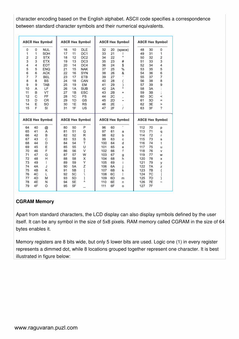
character encoding based on the English alphabet. ASCII code specifies a correspondence
between standard character symbols and their numerical equivalents.
CGRAM Memory
Apart from standard characters, the LCD display can also display symbols defined by the user
itself. It can be any symbol in the size of 5x8 pixels. RAM memory called CGRAM in the size of 64
bytes enables it.
Memory registers are 8 bits wide, but only 5 lower bits are used. Logic one (1) in every register
represents a dimmed dot, while 8 locations grouped together represent one character. It is best
illustrated in figure below:
www.raguvaran.puzl.com
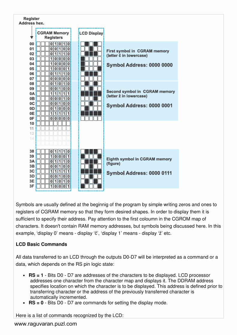
Symbols are usually defined at the beginnig of the program by simple writing zeros and ones to
registers of CGRAM memory so that they form desired shapes. In order to display them it is
sufficient to specify their address. Pay attention to the first coloumn in the CGROM map of
characters. It doesn't contain RAM memory addresses, but symbols being discussed here. In this
example, ‘display 0’ means - display ‘č’, ‘display 1’ means - display ‘ž’ etc.
LCD Basic Commands
All data transferred to an LCD through the outputs D0-D7 will be interpreted as a command or a
data, which depends on the RS pin logic state:
• RS = 1 - Bits D0 - D7 are addresses of the characters to be displayed. LCD processor addresses one character from the character map and displays it. The DDRAM address specifies location on which the character is to be displayed. This address is defined prior to transferring character or the address of the previously transferred character is automatically incremented.
• RS = 0 - Bits D0 - D7 are commands for setting the display mode.
Here is a list of commands recognized by the LCD:
www.raguvaran.puzl.com
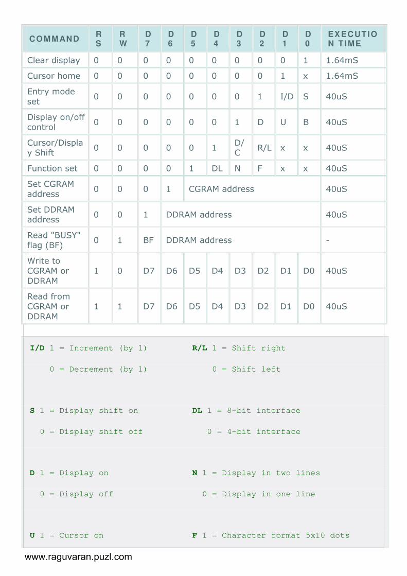
COMMAND RS
RW
D7
D6
D5
D4
D3
D2
D1
D0
EXECUTION TIME
Clear display 0 0 0 0 0 0 0 0 0 1 1.64mS
Cursor home 0 0 0 0 0 0 0 0 1 x 1.64mS
Entry mode
set 0 0 0 0 0 0 0 1 I/D S 40uS
Display on/off
control 0 0 0 0 0 0 1 D U B 40uS
Cursor/Display Shift
0 0 0 0 0 1 D/C
R/L x x 40uS
Function set 0 0 0 0 1 DL N F x x 40uS
Set CGRAM
address 0 0 0 1 CGRAM address 40uS
Set DDRAM address
0 0 1 DDRAM address 40uS
Read "BUSY" flag (BF)
0 1 BF DDRAM address -
Write to
CGRAM or
DDRAM
1 0 D7 D6 D5 D4 D3 D2 D1 D0 40uS
Read from CGRAM or
DDRAM
1 1 D7 D6 D5 D4 D3 D2 D1 D0 40uS
I/D 1 = Increment (by 1) R/L 1 = Shift right
0 = Decrement (by 1) 0 = Shift left
S 1 = Display shift on DL 1 = 8-bit interface
0 = Display shift off 0 = 4-bit interface
D 1 = Display on N 1 = Display in two lines
0 = Display off 0 = Display in one line
U 1 = Cursor on F 1 = Character format 5x10 dots
www.raguvaran.puzl.com
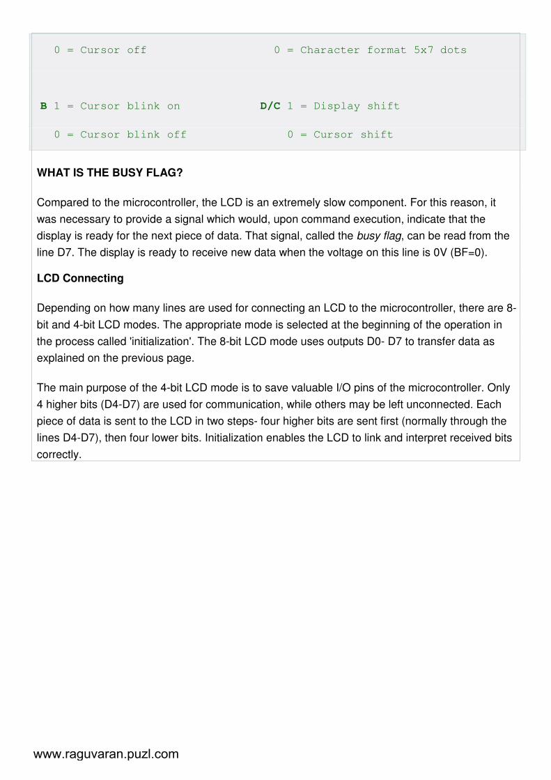
0 = Cursor off 0 = Character format 5x7 dots
B 1 = Cursor blink on D/C 1 = Display shift
0 = Cursor blink off 0 = Cursor shift
WHAT IS THE BUSY FLAG?
Compared to the microcontroller, the LCD is an extremely slow component. For this reason, it
was necessary to provide a signal which would, upon command execution, indicate that the
display is ready for the next piece of data. That signal, called the busy flag, can be read from the
line D7. The display is ready to receive new data when the voltage on this line is 0V (BF=0).
LCD Connecting
Depending on how many lines are used for connecting an LCD to the microcontroller, there are 8-
bit and 4-bit LCD modes. The appropriate mode is selected at the beginning of the operation in
the process called 'initialization'. The 8-bit LCD mode uses outputs D0- D7 to transfer data as
explained on the previous page.
The main purpose of the 4-bit LCD mode is to save valuable I/O pins of the microcontroller. Only
4 higher bits (D4-D7) are used for communication, while others may be left unconnected. Each
piece of data is sent to the LCD in two steps- four higher bits are sent first (normally through the
lines D4-D7), then four lower bits. Initialization enables the LCD to link and interpret received bits
correctly.
www.raguvaran.puzl.com
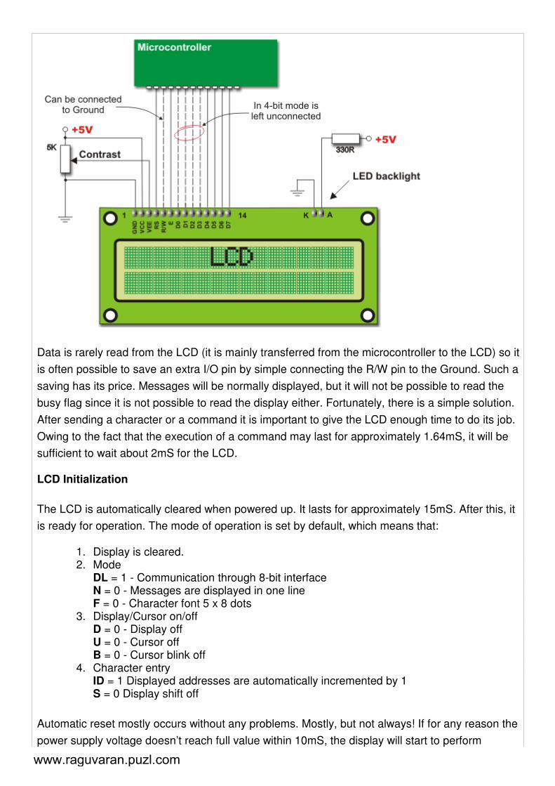
Data is rarely read from the LCD (it is mainly transferred from the microcontroller to the LCD) so it
is often possible to save an extra I/O pin by simple connecting the R/W pin to the Ground. Such a
saving has its price. Messages will be normally displayed, but it will not be possible to read the
busy flag since it is not possible to read the display either. Fortunately, there is a simple solution.
After sending a character or a command it is important to give the LCD enough time to do its job.
Owing to the fact that the execution of a command may last for approximately 1.64mS, it will be
sufficient to wait about 2mS for the LCD.
LCD Initialization
The LCD is automatically cleared when powered up. It lasts for approximately 15mS. After this, it
is ready for operation. The mode of operation is set by default, which means that:
1. Display is cleared. 2. Mode
DL = 1 - Communication through 8-bit interface N = 0 - Messages are displayed in one line F = 0 - Character font 5 x 8 dots
3. Display/Cursor on/off D = 0 - Display off U = 0 - Cursor off B = 0 - Cursor blink off
4. Character entry ID = 1 Displayed addresses are automatically incremented by 1 S = 0 Display shift off
Automatic reset mostly occurs without any problems. Mostly, but not always! If for any reason the
power supply voltage doesn’t reach full value within 10mS, the display will start to perform
www.raguvaran.puzl.com
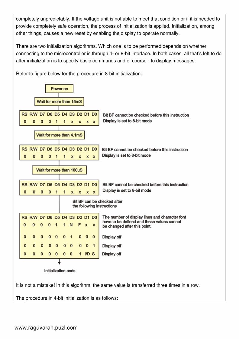
completely unpredictably. If the voltage unit is not able to meet that condition or if it is needed to
provide completely safe operation, the process of initialization is applied. Initialization, among
other things, causes a new reset by enabling the display to operate normally.
There are two initialization algorithms. Which one is to be performed depends on whether
connecting to the microcontroller is through 4- or 8-bit interface. In both cases, all that’s left to do
after initialization is to specify basic commands and of course - to display messages.
Refer to figure below for the procedure in 8-bit initialization:
It is not a mistake! In this algorithm, the same value is transferred three times in a row.
The procedure in 4-bit initialization is as follows:
www.raguvaran.puzl.com
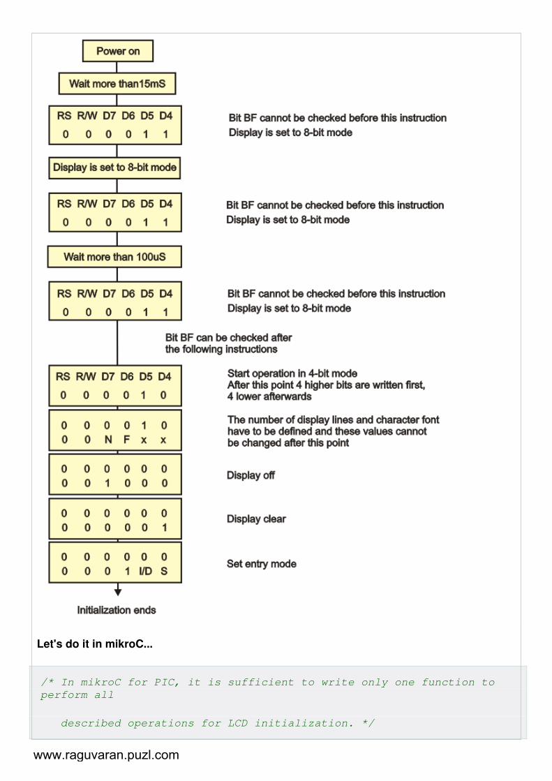
Let's do it in mikroC...
/* In mikroC for PIC, it is sufficient to write only one function to
perform all
described operations for LCD initialization. */
www.raguvaran.puzl.com
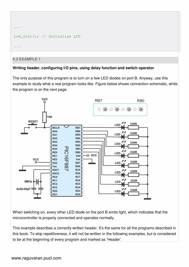
...
Lcd_Init(); // Initialize LCD
...
4.3 EXAMPLE 1
Writing header, configuring I/O pins, using delay function and switch operator
The only purpose of this program is to turn on a few LED diodes on port B. Anyway, use this
example to study what a real program looks like. Figure below shows connection schematic, while
the program is on the next page.
When switching on, every other LED diode on the port B emits light, which indicates that the
microcontroller is properly connected and operates normally.
This example describes a correctly written header. It’s the same for all the programs described in
this book. To skip repetitiveness, it will not be written in the following examples, but is considered
to be at the beginning of every program and marked as ‘Header’.
www.raguvaran.puzl.com
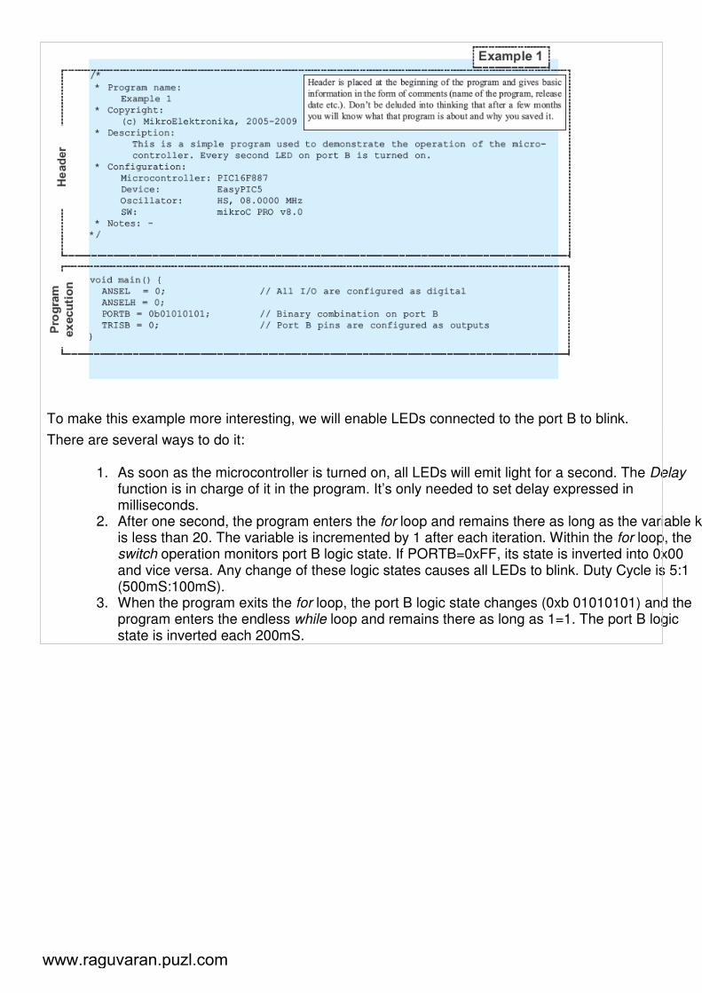
To make this example more interesting, we will enable LEDs connected to the port B to blink.
There are several ways to do it:
1. As soon as the microcontroller is turned on, all LEDs will emit light for a second. The Delay function is in charge of it in the program. It’s only needed to set delay expressed in milliseconds.
2. After one second, the program enters the for loop and remains there as long as the variable k is less than 20. The variable is incremented by 1 after each iteration. Within the for loop, the switch operation monitors port B logic state. If PORTB=0xFF, its state is inverted into 0x00 and vice versa. Any change of these logic states causes all LEDs to blink. Duty Cycle is 5:1 (500mS:100mS).
3. When the program exits the for loop, the port B logic state changes (0xb 01010101) and the program enters the endless while loop and remains there as long as 1=1. The port B logic state is inverted each 200mS.
www.raguvaran.puzl.com
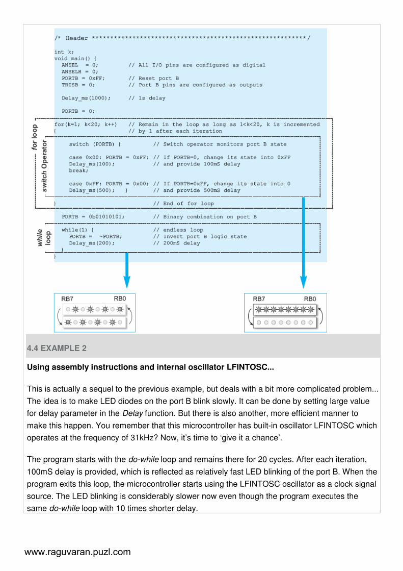
4.4 EXAMPLE 2
Using assembly instructions and internal oscillator LFINTOSC...
This is actually a sequel to the previous example, but deals with a bit more complicated problem...
The idea is to make LED diodes on the port B blink slowly. It can be done by setting large value
for delay parameter in the Delay function. But there is also another, more efficient manner to
make this happen. You remember that this microcontroller has built-in oscillator LFINTOSC which
operates at the frequency of 31kHz? Now, it’s time to ‘give it a chance’.
The program starts with the do-while loop and remains there for 20 cycles. After each iteration,
100mS delay is provided, which is reflected as relatively fast LED blinking of the port B. When the
program exits this loop, the microcontroller starts using the LFINTOSC oscillator as a clock signal
source. The LED blinking is considerably slower now even though the program executes the
same do-while loop with 10 times shorter delay.
www.raguvaran.puzl.com
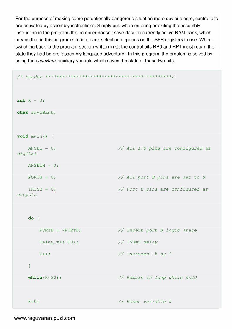
For the purpose of making some potentionally dangerous situation more obvious here, control bits
are activated by assembly instructions. Simply put, when entering or exiting the assembly
instruction in the program, the compiler doesn’t save data on currently active RAM bank, which
means that in this program section, bank selection depends on the SFR registers in use. When
switching back to the program section written in C, the control bits RP0 and RP1 must return the
state they had before ‘assembly language adventure’. In this program, the problem is solved by
using the saveBank auxiliary variable which saves the state of these two bits.
/* Header *********************************************/
int k = 0;
char saveBank;
void main()
ANSEL = 0; // All I/O pins are configured as
digital
ANSELH = 0;
PORTB = 0; // All port B pins are set to 0
TRISB = 0; // Port B pins are configured as
outputs
do
PORTB = ~PORTB; // Invert port B logic state
Delay_ms(100); // 100mS delay
k++; // Increment k by 1
while(k<20); // Remain in loop while k<20
k=0; // Reset variable k
www.raguvaran.puzl.com
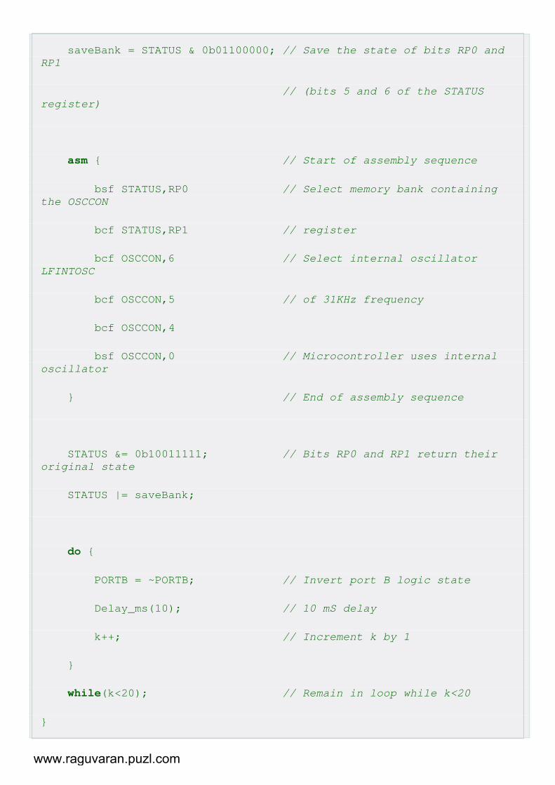
saveBank = STATUS & 0b01100000; // Save the state of bits RP0 and
RP1
// (bits 5 and 6 of the STATUS
register)
asm // Start of assembly sequence
bsf STATUS,RP0 // Select memory bank containing
the OSCCON
bcf STATUS,RP1 // register
bcf OSCCON,6 // Select internal oscillator
LFINTOSC
bcf OSCCON,5 // of 31KHz frequency
bcf OSCCON,4
bsf OSCCON,0 // Microcontroller uses internal
oscillator
// End of assembly sequence
STATUS &= 0b10011111; // Bits RP0 and RP1 return their
original state
STATUS |= saveBank;
do
PORTB = ~PORTB; // Invert port B logic state
Delay_ms(10); // 10 mS delay
k++; // Increment k by 1
while(k<20); // Remain in loop while k<20
www.raguvaran.puzl.com
You have noticed that the clock signal source is changed ‘on the fly’. If you want to make sure of
it, remove quartz crystal prior to switching the microcontroller on. The microcontroller will not start
to operate because the Config Word loaded with the program requires the use of crystal on
switching on. If you remove the crystal later during operation, nothing will happen, it will not affect
the microcontroller at all.
4.5 EXAMPLE 3
TMR0 as a counter, declaring new variables, enumerated constants, using relay ...
Referring to the previous examples, the microcontroller executes the program without being
affected in any way by its surrounding. Practically, devices operating in this manner are very rare
(for example, simple neon sign controller). Input pins are also used in this example. There is a
schematic in figure below, while the program is on the next page. It’s still very simple. Timer
TMR0 is used as a counter. The counter input is connected to a push button so that any button
press causes timer TMR0 to count one pulse. When the number of pulses matches the number
stored in the TEST register, a logic one (5V) appears on the pin PORTD.3. This voltage activates
an electromechanical relay, and this bit is called ‘RELAY’ in the program, therefore.
In this example, the TEST register stores number 5. Of course, it can be any number obtained
either by computing or defined as a constant. Besides, the microcontroller can activate some
other device instead of relay, while the sensor can be used instead of the push button. This
example illustrates one of the most common applications of the microcontroller in the industry;
when something is performed as many times as needed, then something else should be turned
on or off....
www.raguvaran.puzl.com
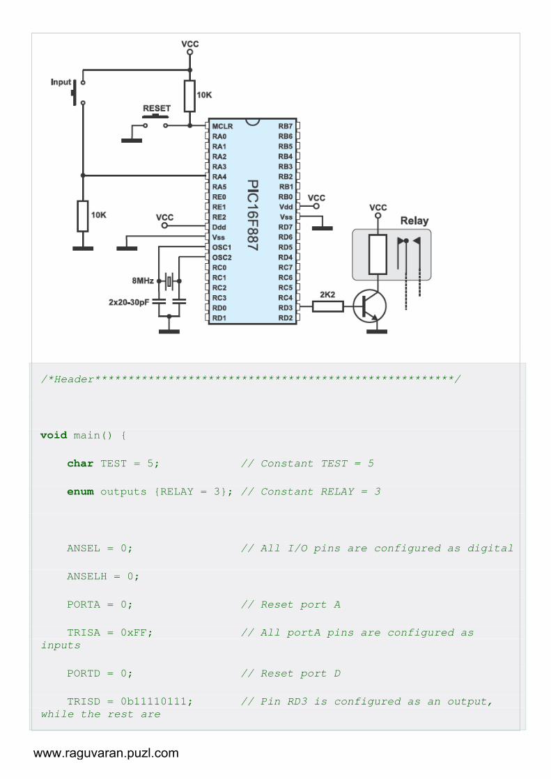
/*Header******************************************************/
void main()
char TEST = 5; // Constant TEST = 5
enum outputs RELAY = 3; // Constant RELAY = 3
ANSEL = 0; // All I/O pins are configured as digital
ANSELH = 0;
PORTA = 0; // Reset port A
TRISA = 0xFF; // All portA pins are configured as
inputs
PORTD = 0; // Reset port D
TRISD = 0b11110111; // Pin RD3 is configured as an output,
while the rest are
www.raguvaran.puzl.com
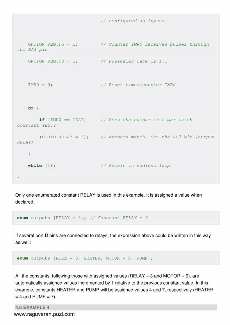
// configured as inputs
OPTION_REG.F5 = 1; // Counter TMR0 receives pulses through
the RA4 pin
OPTION_REG.F3 = 1; // Prescaler rate is 1:1
TMR0 = 0; // Reset timer/counter TMR0
do
if (TMR0 == TEST) // Does the number in timer match
constant TEST?
(PORTD.RELAY = 1); // Numbers match. Set the RD3 bit (output
RELAY)
while (1); // Remain in endless loop
Only one enumerated constant RELAY is used in this example. It is assigned a value when
declared.
enum outputs RELAY = 3; // Constant RELAY = 3
If several port D pins are connected to relays, the expression above could be written in this way
as well:
enum outputs RELE = 3, HEATER, MOTOR = 6, PUMP;
All the constants, following those with assigned values (RELAY = 3 and MOTOR = 6), are
automatically assigned values incremented by 1 relative to the previous constant value. In this
example, constants HEATER and PUMP will be assigned values 4 and 7, respectively (HEATER
= 4 and PUMP = 7).
4.6 EXAMPLE 4
www.raguvaran.puzl.com
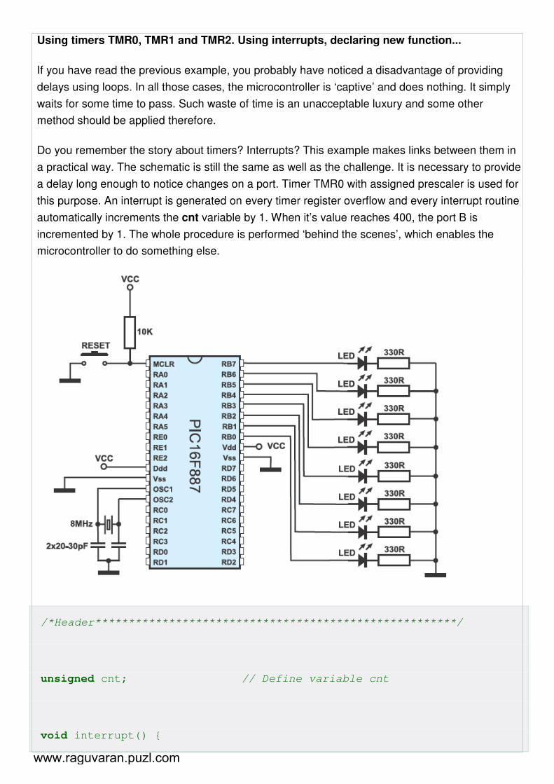
Using timers TMR0, TMR1 and TMR2. Using interrupts, declaring new function...
If you have read the previous example, you probably have noticed a disadvantage of providing
delays using loops. In all those cases, the microcontroller is ‘captive’ and does nothing. It simply
waits for some time to pass. Such waste of time is an unacceptable luxury and some other
method should be applied therefore.
Do you remember the story about timers? Interrupts? This example makes links between them in
a practical way. The schematic is still the same as well as the challenge. It is necessary to provide
a delay long enough to notice changes on a port. Timer TMR0 with assigned prescaler is used for
this purpose. An interrupt is generated on every timer register overflow and every interrupt routine
automatically increments the cnt variable by 1. When it’s value reaches 400, the port B is
incremented by 1. The whole procedure is performed ‘behind the scenes’, which enables the
microcontroller to do something else.
/*Header******************************************************/
unsigned cnt; // Define variable cnt
void interrupt()
www.raguvaran.puzl.com
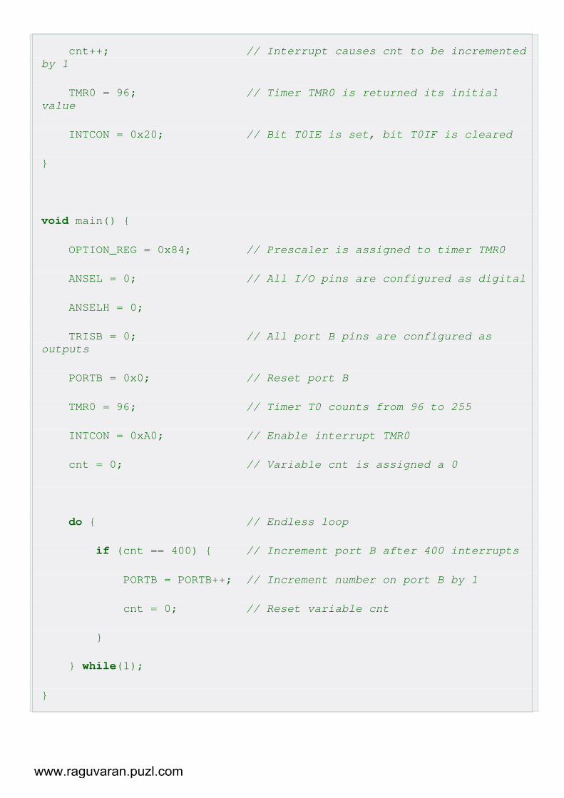
cnt++; // Interrupt causes cnt to be incremented
by 1
TMR0 = 96; // Timer TMR0 is returned its initial
value
INTCON = 0x20; // Bit T0IE is set, bit T0IF is cleared
void main()
OPTION_REG = 0x84; // Prescaler is assigned to timer TMR0
ANSEL = 0; // All I/O pins are configured as digital
ANSELH = 0;
TRISB = 0; // All port B pins are configured as
outputs
PORTB = 0x0; // Reset port B
TMR0 = 96; // Timer T0 counts from 96 to 255
INTCON = 0xA0; // Enable interrupt TMR0
cnt = 0; // Variable cnt is assigned a 0
do // Endless loop
if (cnt == 400) // Increment port B after 400 interrupts
PORTB = PORTB++; // Increment number on port B by 1
cnt = 0; // Reset variable cnt
while(1);
www.raguvaran.puzl.com
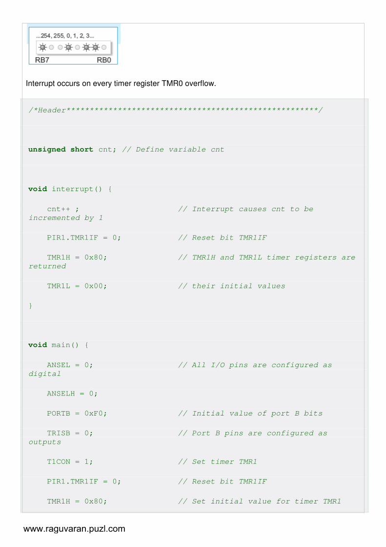
Interrupt occurs on every timer register TMR0 overflow.
/*Header******************************************************/
unsigned short cnt; // Define variable cnt
void interrupt()
cnt++ ; // Interrupt causes cnt to be
incremented by 1
PIR1.TMR1IF = 0; // Reset bit TMR1IF
TMR1H = 0x80; // TMR1H and TMR1L timer registers are
returned
TMR1L = 0x00; // their initial values
void main()
ANSEL = 0; // All I/O pins are configured as
digital
ANSELH = 0;
PORTB = 0xF0; // Initial value of port B bits
TRISB = 0; // Port B pins are configured as
outputs
T1CON = 1; // Set timer TMR1
PIR1.TMR1IF = 0; // Reset bit TMR1IF
TMR1H = 0x80; // Set initial value for timer TMR1
www.raguvaran.puzl.com
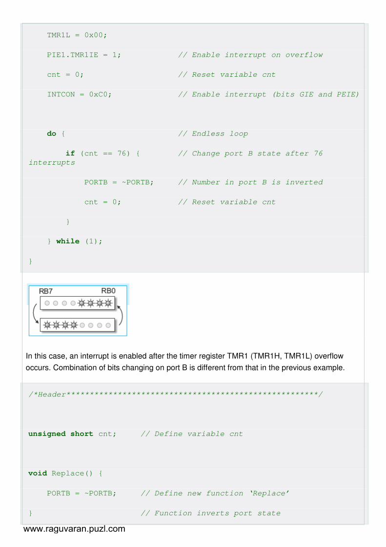
TMR1L = 0x00;
PIE1.TMR1IE = 1; // Enable interrupt on overflow
cnt = 0; // Reset variable cnt
INTCON = 0xC0; // Enable interrupt (bits GIE and PEIE)
do // Endless loop
if (cnt == 76) // Change port B state after 76
interrupts
PORTB = ~PORTB; // Number in port B is inverted
cnt = 0; // Reset variable cnt
while (1);
In this case, an interrupt is enabled after the timer register TMR1 (TMR1H, TMR1L) overflow
occurs. Combination of bits changing on port B is different from that in the previous example.
/*Header******************************************************/
unsigned short cnt; // Define variable cnt
void Replace()
PORTB = ~PORTB; // Define new function ‘Replace’
// Function inverts port state
www.raguvaran.puzl.com
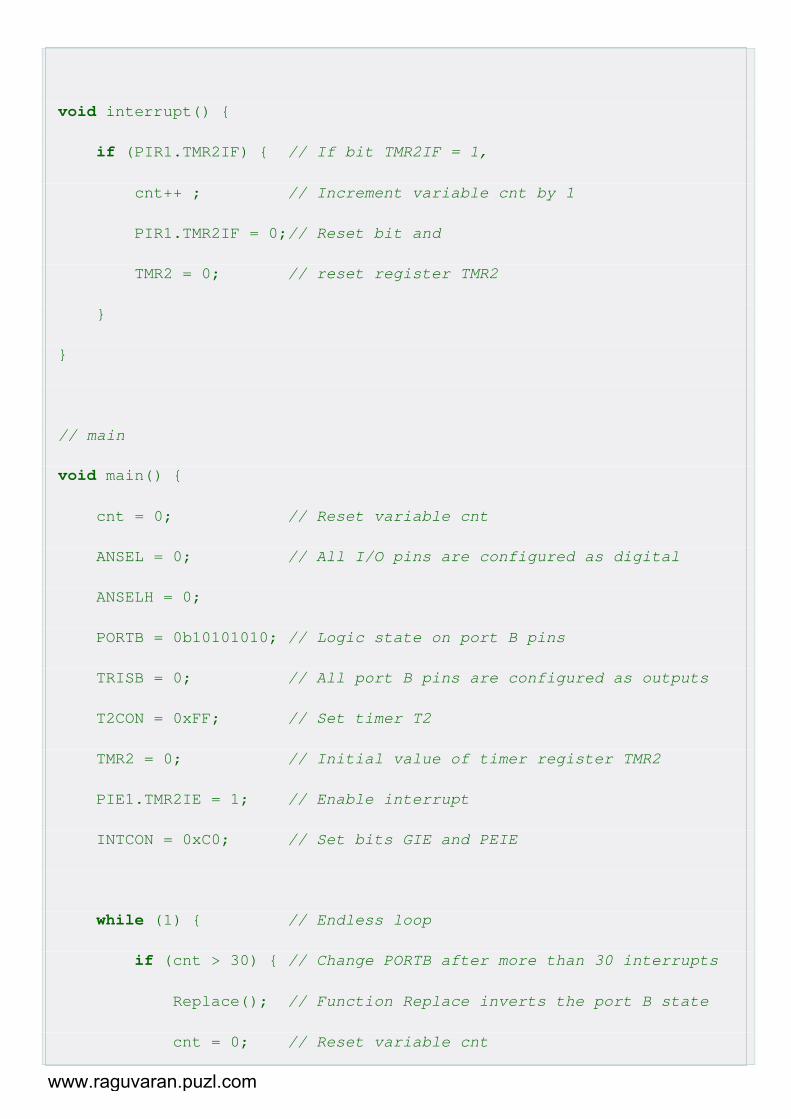
void interrupt()
if (PIR1.TMR2IF) // If bit TMR2IF = 1,
cnt++ ; // Increment variable cnt by 1
PIR1.TMR2IF = 0;// Reset bit and
TMR2 = 0; // reset register TMR2
// main
void main()
cnt = 0; // Reset variable cnt
ANSEL = 0; // All I/O pins are configured as digital
ANSELH = 0;
PORTB = 0b10101010; // Logic state on port B pins
TRISB = 0; // All port B pins are configured as outputs
T2CON = 0xFF; // Set timer T2
TMR2 = 0; // Initial value of timer register TMR2
PIE1.TMR2IE = 1; // Enable interrupt
INTCON = 0xC0; // Set bits GIE and PEIE
while (1) // Endless loop
if (cnt > 30) // Change PORTB after more than 30 interrupts
Replace(); // Function Replace inverts the port B state
cnt = 0; // Reset variable cnt
www.raguvaran.puzl.com
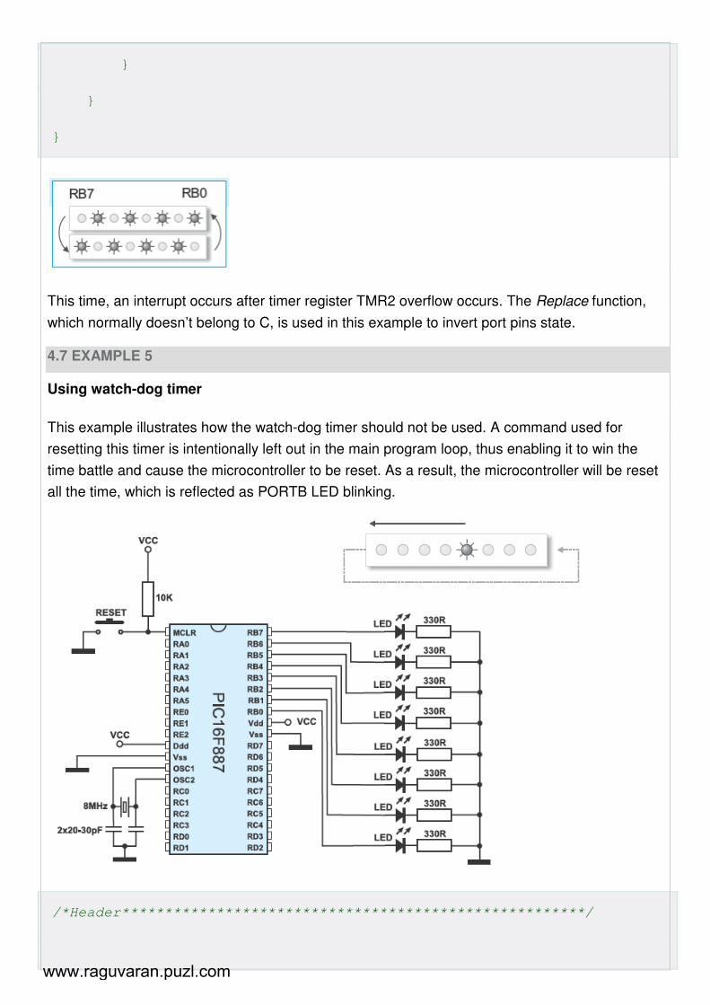
This time, an interrupt occurs after timer register TMR2 overflow occurs. The Replace function,
which normally doesn’t belong to C, is used in this example to invert port pins state.
4.7 EXAMPLE 5
Using watch-dog timer
This example illustrates how the watch-dog timer should not be used. A command used for
resetting this timer is intentionally left out in the main program loop, thus enabling it to win the
time battle and cause the microcontroller to be reset. As a result, the microcontroller will be reset
all the time, which is reflected as PORTB LED blinking.
/*Header******************************************************/
www.raguvaran.puzl.com
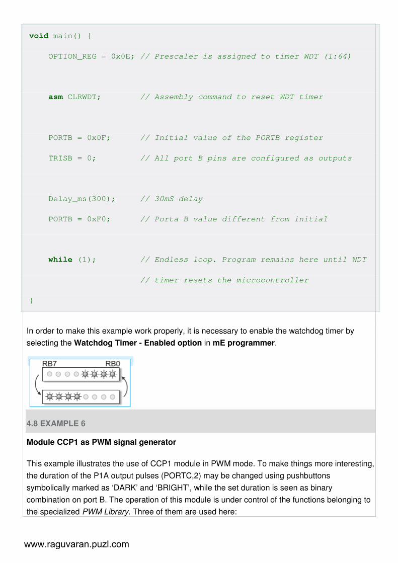
void main()
OPTION_REG = 0x0E; // Prescaler is assigned to timer WDT (1:64)
asm CLRWDT; // Assembly command to reset WDT timer
PORTB = 0x0F; // Initial value of the PORTB register
TRISB = 0; // All port B pins are configured as outputs
Delay_ms(300); // 30mS delay
PORTB = 0xF0; // Porta B value different from initial
while (1); // Endless loop. Program remains here until WDT
// timer resets the microcontroller
In order to make this example work properly, it is necessary to enable the watchdog timer by
selecting the Watchdog Timer - Enabled option in mE programmer.
4.8 EXAMPLE 6
Module CCP1 as PWM signal generator
This example illustrates the use of CCP1 module in PWM mode. To make things more interesting,
the duration of the P1A output pulses (PORTC,2) may be changed using pushbuttons
symbolically marked as ‘DARK’ and ‘BRIGHT’, while the set duration is seen as binary
combination on port B. The operation of this module is under control of the functions belonging to
the specialized PWM Library. Three of them are used here:
www.raguvaran.puzl.com
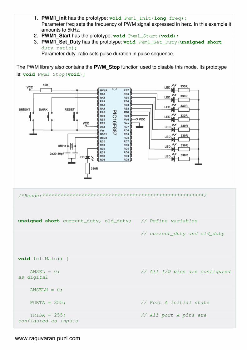
1. PWM1_init has the prototype: void Pwm1_Init(long freq); Parameter freq sets the frequency of PWM signal expressed in herz. In this example it amounts to 5kHz.
2. PWM1_Start has the prototype: void Pwm1_Start(void);
3. PWM1_Set_Duty has the prototype: void Pwm1_Set_Duty(unsigned short duty_ratio); Parameter duty_ratio sets pulse duration in pulse sequence.
The PWM library also contains the PWM_Stop function used to disable this mode. Its prototype
is: void Pwm1_Stop(void);
/*Header******************************************************/
unsigned short current_duty, old_duty; // Define variables
// current_duty and old_duty
void initMain()
ANSEL = 0; // All I/O pins are configured
as digital
ANSELH = 0;
PORTA = 255; // Port A initial state
TRISA = 255; // All port A pins are
configured as inputs
www.raguvaran.puzl.com
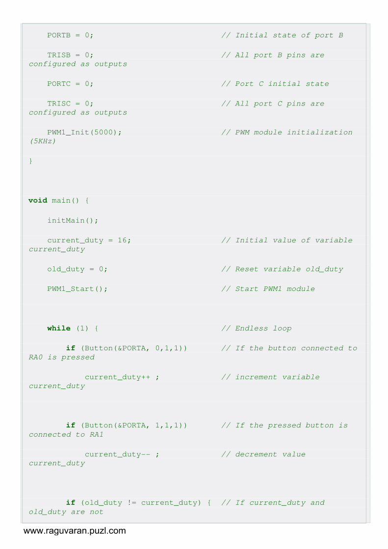
PORTB = 0; // Initial state of port B
TRISB = 0; // All port B pins are
configured as outputs
PORTC = 0; // Port C initial state
TRISC = 0; // All port C pins are
configured as outputs
PWM1_Init(5000); // PWM module initialization
(5KHz)
void main()
initMain();
current_duty = 16; // Initial value of variable
current_duty
old_duty = 0; // Reset variable old_duty
PWM1_Start(); // Start PWM1 module
while (1) // Endless loop
if (Button(&PORTA, 0,1,1)) // If the button connected to
RA0 is pressed
current_duty++ ; // increment variable
current_duty
if (Button(&PORTA, 1,1,1)) // If the pressed button is
connected to RA1
current_duty-- ; // decrement value
current_duty
if (old_duty != current_duty) // If current_duty and
old_duty are not
www.raguvaran.puzl.com

PWM1_Set_Duty(current_duty); // equal set PWM to a new
value,
old_duty = current_duty; // save the new value
PORTB = old_duty; // and show it on port B
Delay_ms(200); // 200mS delay
In order to make this example work properly, it is necessary to tick off the following libraries in the
Library Manager prior to compiling:
• PWM • Button
4.9 EXAMPLE 7
Using A/D converter
The PIC16F887 A/D converter is used in this example. Is it necessary to mention that everything
is rather simple?! A variable analog signal is applied to the AN2 pin, while the 10-bit result of
conversion is shown on ports B and D (8 LSBs on port D and 2 MSBs on port B). GND is used as
negative voltage reference Vref-, while positive voltage reference is applied to the AN3 pin. It
enables voltage measurement scale to 'stretch and shrink'.
In other words, the A/D converter always generates a 10-bit binary result, which means that it
detects a total of 1024 voltage levels (210=1024). The difference between two voltage levels is
not always the same. The less the difference between Vref+ and Vref-, the less the difference
between two of 1024 levels. As seen, the A/D converter is able to detect slight changes in
voltage.
www.raguvaran.puzl.com
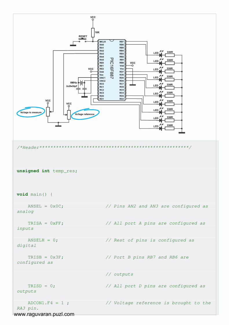
/*Header******************************************************/
unsigned int temp_res;
void main()
ANSEL = 0x0C; // Pins AN2 and AN3 are configured as
analog
TRISA = 0xFF; // All port A pins are configured as
inputs
ANSELH = 0; // Rest of pins is configured as
digital
TRISB = 0x3F; // Port B pins RB7 and RB6 are
configured as
// outputs
TRISD = 0; // All port D pins are configured as
outputs
ADCON1.F4 = 1 ; // Voltage reference is brought to the
RA3 pin.
www.raguvaran.puzl.com
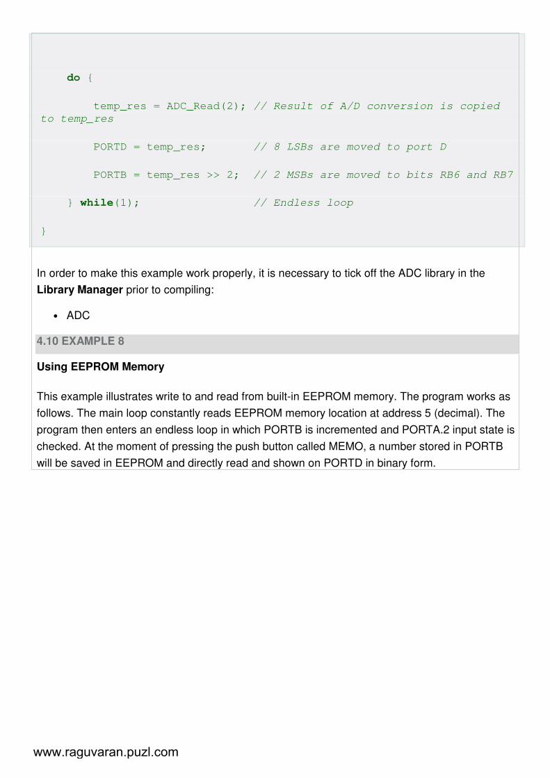
do
temp_res = ADC_Read(2); // Result of A/D conversion is copied
to temp_res
PORTD = temp_res; // 8 LSBs are moved to port D
PORTB = temp_res >> 2; // 2 MSBs are moved to bits RB6 and RB7
while(1); // Endless loop
In order to make this example work properly, it is necessary to tick off the ADC library in the
Library Manager prior to compiling:
• ADC
4.10 EXAMPLE 8
Using EEPROM Memory
This example illustrates write to and read from built-in EEPROM memory. The program works as
follows. The main loop constantly reads EEPROM memory location at address 5 (decimal). The
program then enters an endless loop in which PORTB is incremented and PORTA.2 input state is
checked. At the moment of pressing the push button called MEMO, a number stored in PORTB
will be saved in EEPROM and directly read and shown on PORTD in binary form.
www.raguvaran.puzl.com
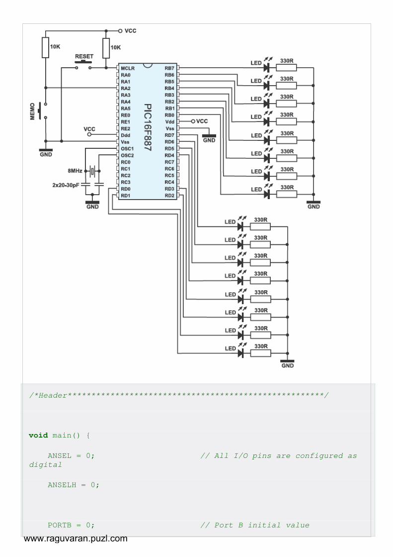
/*Header******************************************************/
void main()
ANSEL = 0; // All I/O pins are configured as
digital
ANSELH = 0;
PORTB = 0; // Port B initial value
www.raguvaran.puzl.com
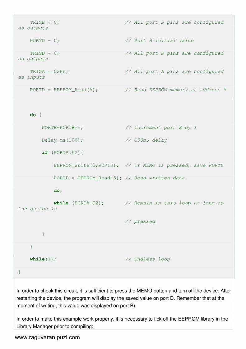
TRISB = 0; // All port B pins are configured
as outputs
PORTD = 0; // Port B initial value
TRISD = 0; // All port D pins are configured
as outputs
TRISA = 0xFF; // All port A pins are configured
as inputs
PORTD = EEPROM_Read(5); // Read EEPROM memory at address 5
do
PORTB=PORTB++; // Increment port B by 1
Delay_ms(100); // 100mS delay
if (PORTA.F2)
EEPROM_Write(5,PORTB); // If MEMO is pressed, save PORTB
PORTD = EEPROM_Read(5); // Read written data
do;
while (PORTA.F2); // Remain in this loop as long as
the button is
// pressed
while(1); // Endless loop
In order to check this circuit, it is sufficient to press the MEMO button and turn off the device. After
restarting the device, the program will display the saved value on port D. Remember that at the
moment of writing, this value was displayed on port B).
In order to make this example work properly, it is necessary to tick off the EEPROM library in the
Library Manager prior to compiling:
www.raguvaran.puzl.com
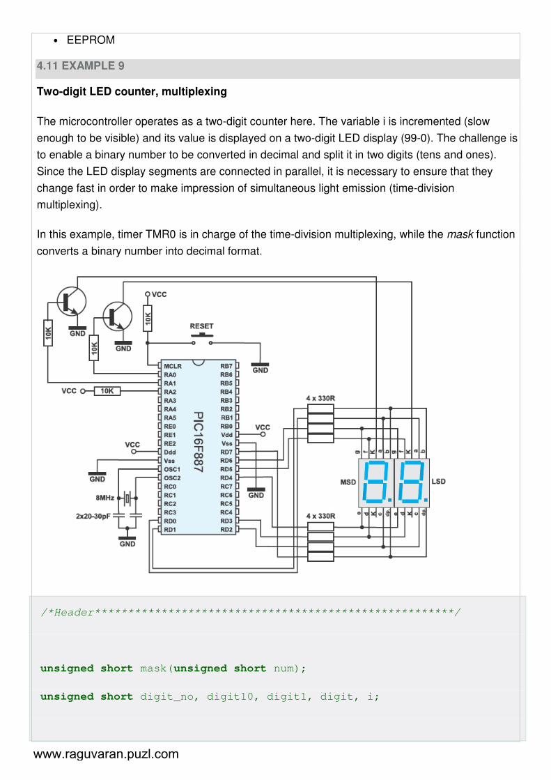
• EEPROM
4.11 EXAMPLE 9
Two-digit LED counter, multiplexing
The microcontroller operates as a two-digit counter here. The variable i is incremented (slow
enough to be visible) and its value is displayed on a two-digit LED display (99-0). The challenge is
to enable a binary number to be converted in decimal and split it in two digits (tens and ones).
Since the LED display segments are connected in parallel, it is necessary to ensure that they
change fast in order to make impression of simultaneous light emission (time-division
multiplexing).
In this example, timer TMR0 is in charge of the time-division multiplexing, while the mask function
converts a binary number into decimal format.
/*Header******************************************************/
unsigned short mask(unsigned short num);
unsigned short digit_no, digit10, digit1, digit, i;
www.raguvaran.puzl.com
void interrupt()
if (digit_no==0)
PORTA = 0; // Turn off both displays
PORTD = digit1; // Set mask for displaying ones on
PORTD
PORTA = 1; // Turn on display for ones (LSD)
digit_no = 1;
else
PORTA = 0; // Turn off both displays
PORTD = digit10; // Set mask for displaying tens on
PORTD
PORTA = 2; // Turn on display for tens (MSD)
digit_no = 0;
TMR0 = 0; // Reset counter TMRO
INTCON = 0x20; // Bit T0IF=0, T0IE=1
void main()
OPTION_REG = 0x80; // Set timer TMR0
TMR0 = 0;
INTCON = 0xA0; // Disable interrupt
PEIE,INTE,RBIE,T0IE
PORTA = 0; // Turn off both displays
TRISA = 0; // All port A pins are configured as
outputs
PORTD = 0; // Turn off all display segments
www.raguvaran.puzl.com
TRISD = 0; // All port D pins are configured as
outputs
do
for (i = 0; i<=99; i++) // Count from 0 to 99
digit = i % 10u;
digit1 = mask(digit); // Prepare mask for displaying ones
digit = (char)(i / 10u) % 10u;
digit10 = mask(digit); // Prepare mask for displaying tens
Delay_ms(1000);
while (1); // Endless loop
mask.c file:
/*Header******************************************************/
unsigned short mask(unsigned short num)
switch (num)
case 0 : return 0x3F;
case 1 : return 0x06;
case 2 : return 0x5B;
case 3 : return 0x4F;
case 4 : return 0x66;
case 5 : return 0x6D;
case 6 : return 0x7D;
case 7 : return 0x07;
www.raguvaran.puzl.com
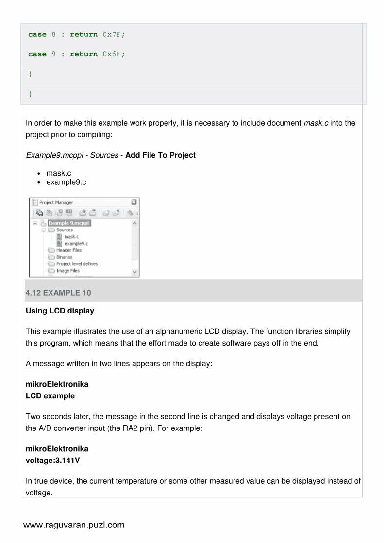
case 8 : return 0x7F;
case 9 : return 0x6F;
In order to make this example work properly, it is necessary to include document mask.c into the
project prior to compiling:
Example9.mcppi - Sources - Add File To Project
• mask.c • example9.c
4.12 EXAMPLE 10
Using LCD display
This example illustrates the use of an alphanumeric LCD display. The function libraries simplify
this program, which means that the effort made to create software pays off in the end.
A message written in two lines appears on the display:
mikroElektronika
LCD example
Two seconds later, the message in the second line is changed and displays voltage present on
the A/D converter input (the RA2 pin). For example:
mikroElektronika
voltage:3.141V
In true device, the current temperature or some other measured value can be displayed instead of
voltage.
www.raguvaran.puzl.com
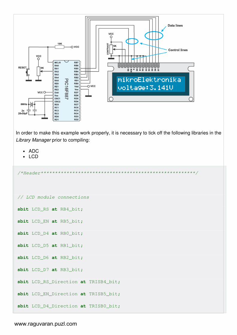
In order to make this example work properly, it is necessary to tick off the following libraries in the
Library Manager prior to compiling:
• ADC • LCD
/*Header******************************************************/
// LCD module connections
sbit LCD_RS at RB4_bit;
sbit LCD_EN at RB5_bit;
sbit LCD_D4 at RB0_bit;
sbit LCD_D5 at RB1_bit;
sbit LCD_D6 at RB2_bit;
sbit LCD_D7 at RB3_bit;
sbit LCD_RS_Direction at TRISB4_bit;
sbit LCD_EN_Direction at TRISB5_bit;
sbit LCD_D4_Direction at TRISB0_bit;
www.raguvaran.puzl.com
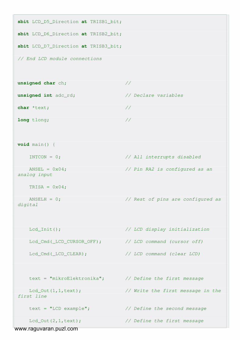
sbit LCD_D5_Direction at TRISB1_bit;
sbit LCD_D6_Direction at TRISB2_bit;
sbit LCD_D7_Direction at TRISB3_bit;
// End LCD module connections
unsigned char ch; //
unsigned int adc_rd; // Declare variables
char *text; //
long tlong; //
void main()
INTCON = 0; // All interrupts disabled
ANSEL = 0x04; // Pin RA2 is configured as an
analog input
TRISA = 0x04;
ANSELH = 0; // Rest of pins are configured as
digital
Lcd_Init(); // LCD display initialization
Lcd_Cmd(_LCD_CURSOR_OFF); // LCD command (cursor off)
Lcd_Cmd(_LCD_CLEAR); // LCD command (clear LCD)
text = "mikroElektronika"; // Define the first message
Lcd_Out(1,1,text); // Write the first message in the
first line
text = "LCD example"; // Define the second message
Lcd_Out(2,1,text); // Define the first message
www.raguvaran.puzl.com
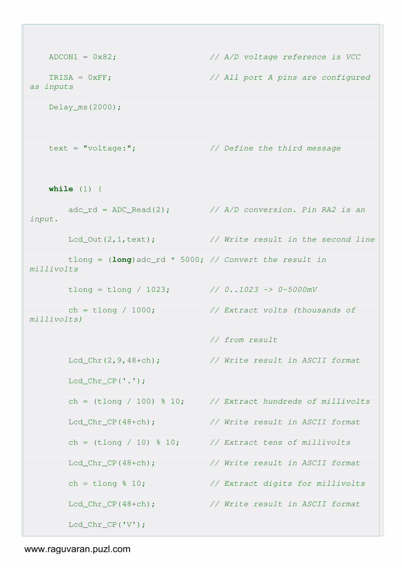
ADCON1 = 0x82; // A/D voltage reference is VCC
TRISA = 0xFF; // All port A pins are configured
as inputs
Delay_ms(2000);
text = "voltage:"; // Define the third message
while (1)
adc_rd = ADC_Read(2); // A/D conversion. Pin RA2 is an
input.
Lcd_Out(2,1,text); // Write result in the second line
tlong = (long)adc_rd * 5000; // Convert the result in
millivolts
tlong = tlong / 1023; // 0..1023 -> 0-5000mV
ch = tlong / 1000; // Extract volts (thousands of
millivolts)
// from result
Lcd_Chr(2,9,48+ch); // Write result in ASCII format
Lcd_Chr_CP('.');
ch = (tlong / 100) % 10; // Extract hundreds of millivolts
Lcd_Chr_CP(48+ch); // Write result in ASCII format
ch = (tlong / 10) % 10; // Extract tens of millivolts
Lcd_Chr_CP(48+ch); // Write result in ASCII format
ch = tlong % 10; // Extract digits for millivolts
Lcd_Chr_CP(48+ch); // Write result in ASCII format
Lcd_Chr_CP('V');
www.raguvaran.puzl.com
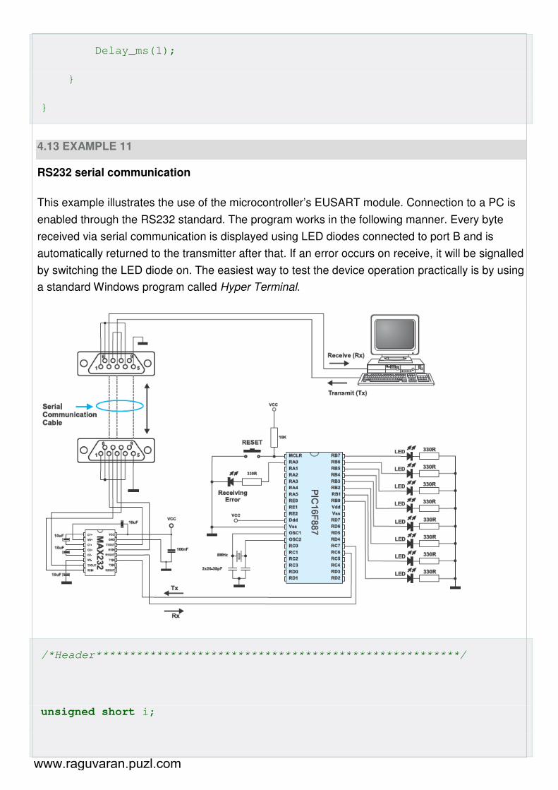
Delay_ms(1);
4.13 EXAMPLE 11
RS232 serial communication
This example illustrates the use of the microcontroller’s EUSART module. Connection to a PC is
enabled through the RS232 standard. The program works in the following manner. Every byte
received via serial communication is displayed using LED diodes connected to port B and is
automatically returned to the transmitter after that. If an error occurs on receive, it will be signalled
by switching the LED diode on. The easiest way to test the device operation practically is by using
a standard Windows program called Hyper Terminal.
/*Header******************************************************/
unsigned short i;
www.raguvaran.puzl.com
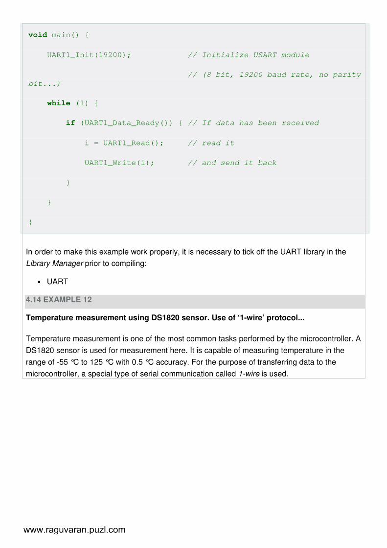
void main()
UART1_Init(19200); // Initialize USART module
// (8 bit, 19200 baud rate, no parity
bit...)
while (1)
if (UART1_Data_Ready()) // If data has been received
i = UART1_Read(); // read it
UART1_Write(i); // and send it back
In order to make this example work properly, it is necessary to tick off the UART library in the
Library Manager prior to compiling:
• UART
4.14 EXAMPLE 12
Temperature measurement using DS1820 sensor. Use of ‘1-wire’ protocol...
Temperature measurement is one of the most common tasks performed by the microcontroller. A
DS1820 sensor is used for measurement here. It is capable of measuring temperature in the
range of -55 °C to 125 °C with 0.5 °C accuracy. For the purpose of transferring data to the
microcontroller, a special type of serial communication called 1-wire is used.
www.raguvaran.puzl.com
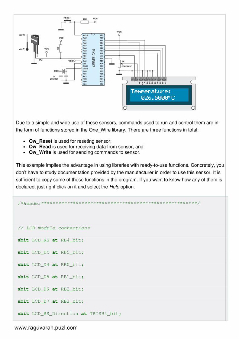
Due to a simple and wide use of these sensors, commands used to run and control them are in
the form of functions stored in the One_Wire library. There are three functions in total:
• Ow_Reset is used for reseting sensor; • Ow_Read is used for receiving data from sensor; and • Ow_Write is used for sending commands to sensor.
This example implies the advantage in using libraries with ready-to-use functions. Concretely, you
don’t have to study documentation provided by the manufacturer in order to use this sensor. It is
sufficient to copy some of these functions in the program. If you want to know how any of them is
declared, just right click on it and select the Help option.
/*Header******************************************************/
// LCD module connections
sbit LCD_RS at RB4_bit;
sbit LCD_EN at RB5_bit;
sbit LCD_D4 at RB0_bit;
sbit LCD_D5 at RB1_bit;
sbit LCD_D6 at RB2_bit;
sbit LCD_D7 at RB3_bit;
sbit LCD_RS_Direction at TRISB4_bit;
www.raguvaran.puzl.com
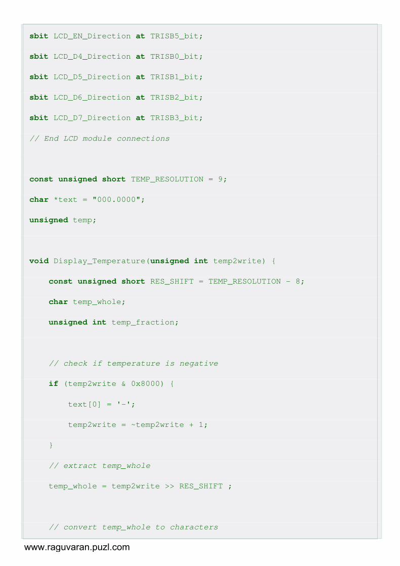
sbit LCD_EN_Direction at TRISB5_bit;
sbit LCD_D4_Direction at TRISB0_bit;
sbit LCD_D5_Direction at TRISB1_bit;
sbit LCD_D6_Direction at TRISB2_bit;
sbit LCD_D7_Direction at TRISB3_bit;
// End LCD module connections
const unsigned short TEMP_RESOLUTION = 9;
char *text = "000.0000";
unsigned temp;
void Display_Temperature(unsigned int temp2write)
const unsigned short RES_SHIFT = TEMP_RESOLUTION - 8;
char temp_whole;
unsigned int temp_fraction;
// check if temperature is negative
if (temp2write & 0x8000)
text[0] = '-';
temp2write = ~temp2write + 1;
// extract temp_whole
temp_whole = temp2write >> RES_SHIFT ;
// convert temp_whole to characters
www.raguvaran.puzl.com
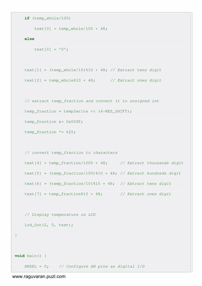
if (temp_whole/100)
text[0] = temp_whole/100 + 48;
else
text[0] = '0';
text[1] = (temp_whole/10)%10 + 48; // Extract tens digit
text[2] = temp_whole%10 + 48; // Extract ones digit
// extract temp_fraction and convert it to unsigned int
temp_fraction = temp2write << (4-RES_SHIFT);
temp_fraction &= 0x000F;
temp_fraction *= 625;
// convert temp_fraction to characters
text[4] = temp_fraction/1000 + 48; // Extract thousands digit
text[5] = (temp_fraction/100)%10 + 48; // Extract hundreds digit
text[6] = (temp_fraction/10)%10 + 48; // Extract tens digit
text[7] = temp_fraction%10 + 48; // Extract ones digit
// Display temperature on LCD
Lcd_Out(2, 5, text);
void main()
ANSEL = 0; // Configure AN pins as digital I/O
www.raguvaran.puzl.com

ANSELH = 0;
C1ON_bit = 0; // Disable comparators
C2ON_bit = 0;
Lcd_Init(); // Initialize LCD
Lcd_Cmd(_LCD_CLEAR); // Clear LCD
Lcd_Cmd(_LCD_CURSOR_OFF); // Turn the cursor off
Lcd_Out(1, 1, " Temperature: ");
// Print degree character, 'C' for Centigrades
Lcd_Chr(2,13,223); // different LCD displays have different
char code for degree
// if you see greek alpha letter try typing 178 instead of 223
Lcd_Chr(2,14,'C');
//--- main loop
do
//--- perform temperature reading
Ow_Reset(&PORTE, 2); // Onewire reset signal
Ow_Write(&PORTE, 2, 0xCC); // Issue command SKIP_ROM
Ow_Write(&PORTE, 2, 0x44); // Issue command CONVERT_T
Delay_us(120);
Ow_Reset(&PORTE, 2);
Ow_Write(&PORTE, 2, 0xCC); // Issue command SKIP_ROM
Ow_Write(&PORTE, 2, 0xBE); // Issue command READ_SCRATCHPAD
www.raguvaran.puzl.com

temp = Ow_Read(&PORTE, 2);
temp = (Ow_Read(&PORTE, 2) << 8) + temp;
//--- Format and display result on Lcd
Display_Temperature(temp);
Delay_ms(500);
while (1);
In order to make this example work properly, it is necessary to tick off the following libraries in the
Library Manager prior to compiling:
• One_Wire • LCD
4.15 EXAMPLE 13
Sound generation, sound library...
Audio signals are often used when it is necessary to call the user’s attention, confirm that some of
the push buttons is pressed, warn that minimum or maximum values are reached etc. It can be
just a ‘beep’ signal as well as longer or shorter melody. This example demonstrates sound
generation using functions belonging to the Sound library.
www.raguvaran.puzl.com
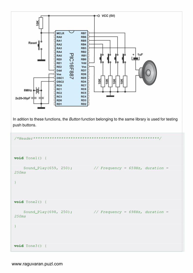
In adition to these functions, the Button function belonging to the same library is used for testing
push buttons.
/*Header******************************************************/
void Tone1()
Sound_Play(659, 250); // Frequency = 659Hz, duration =
250ms
void Tone2()
Sound_Play(698, 250); // Frequency = 698Hz, duration =
250ms
void Tone3()
www.raguvaran.puzl.com
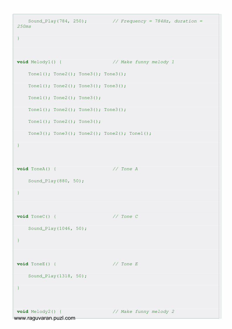
Sound_Play(784, 250); // Frequency = 784Hz, duration =
250ms
void Melody1() // Make funny melody 1
Tone1(); Tone2(); Tone3(); Tone3();
Tone1(); Tone2(); Tone3(); Tone3();
Tone1(); Tone2(); Tone3();
Tone1(); Tone2(); Tone3(); Tone3();
Tone1(); Tone2(); Tone3();
Tone3(); Tone3(); Tone2(); Tone2(); Tone1();
void ToneA() // Tone A
Sound_Play(880, 50);
void ToneC() // Tone C
Sound_Play(1046, 50);
void ToneE() // Tone E
Sound_Play(1318, 50);
void Melody2() // Make funny melody 2
www.raguvaran.puzl.com
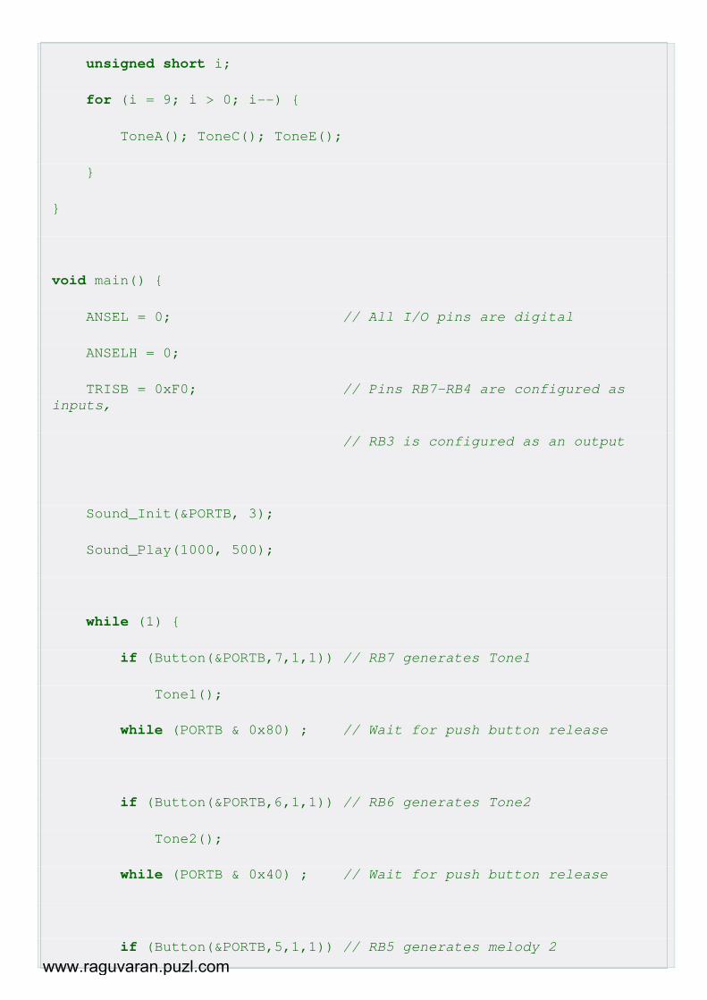
unsigned short i;
for (i = 9; i > 0; i--)
ToneA(); ToneC(); ToneE();
void main()
ANSEL = 0; // All I/O pins are digital
ANSELH = 0;
TRISB = 0xF0; // Pins RB7-RB4 are configured as
inputs,
// RB3 is configured as an output
Sound_Init(&PORTB, 3);
Sound_Play(1000, 500);
while (1)
if (Button(&PORTB,7,1,1)) // RB7 generates Tone1
Tone1();
while (PORTB & 0x80) ; // Wait for push button release
if (Button(&PORTB,6,1,1)) // RB6 generates Tone2
Tone2();
while (PORTB & 0x40) ; // Wait for push button release
if (Button(&PORTB,5,1,1)) // RB5 generates melody 2
www.raguvaran.puzl.com
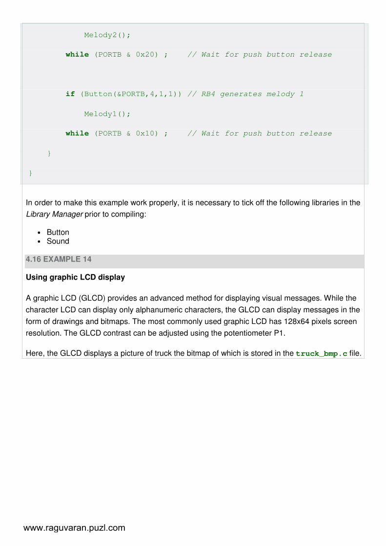
Melody2();
while (PORTB & 0x20) ; // Wait for push button release
if (Button(&PORTB,4,1,1)) // RB4 generates melody 1
Melody1();
while (PORTB & 0x10) ; // Wait for push button release
In order to make this example work properly, it is necessary to tick off the following libraries in the
Library Manager prior to compiling:
• Button • Sound
4.16 EXAMPLE 14
Using graphic LCD display
A graphic LCD (GLCD) provides an advanced method for displaying visual messages. While the
character LCD can display only alphanumeric characters, the GLCD can display messages in the
form of drawings and bitmaps. The most commonly used graphic LCD has 128x64 pixels screen
resolution. The GLCD contrast can be adjusted using the potentiometer P1.
Here, the GLCD displays a picture of truck the bitmap of which is stored in the truck_bmp.c file.
www.raguvaran.puzl.com
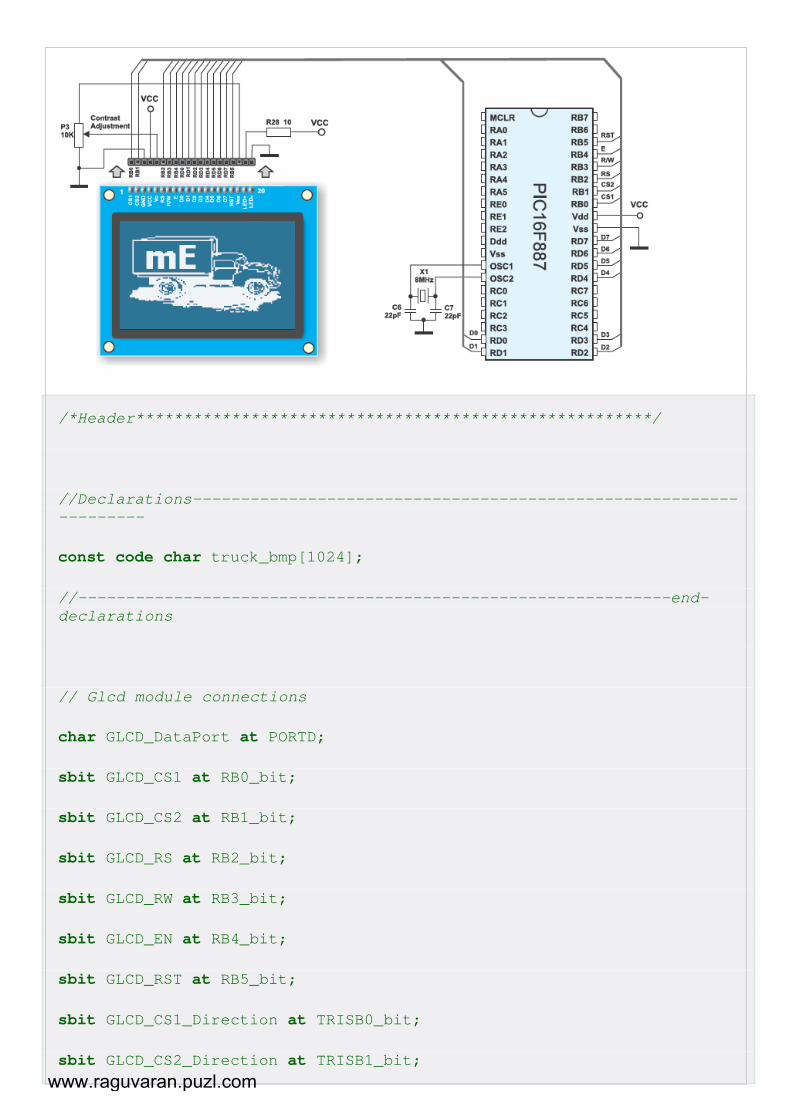
/*Header******************************************************/
//Declarations---------------------------------------------------------
---------
const code char truck_bmp[1024];
//--------------------------------------------------------------end-
declarations
// Glcd module connections
char GLCD_DataPort at PORTD;
sbit GLCD_CS1 at RB0_bit;
sbit GLCD_CS2 at RB1_bit;
sbit GLCD_RS at RB2_bit;
sbit GLCD_RW at RB3_bit;
sbit GLCD_EN at RB4_bit;
sbit GLCD_RST at RB5_bit;
sbit GLCD_CS1_Direction at TRISB0_bit;
sbit GLCD_CS2_Direction at TRISB1_bit;
www.raguvaran.puzl.com
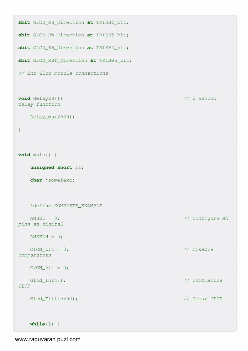
sbit GLCD_RS_Direction at TRISB2_bit;
sbit GLCD_RW_Direction at TRISB3_bit;
sbit GLCD_EN_Direction at TRISB4_bit;
sbit GLCD_RST_Direction at TRISB5_bit;
// End Glcd module connections
void delay2S() // 2 second
delay function
Delay_ms(2000);
void main()
unsigned short ii;
char *someText;
#define COMPLETE_EXAMPLE
ANSEL = 0; // Configure AN
pins as digital
ANSELH = 0;
C1ON_bit = 0; // Disable
comparators
C2ON_bit = 0;
Glcd_Init(); // Initialize
GLCD
Glcd_Fill(0x00); // Clear GLCD
while(1)
www.raguvaran.puzl.com
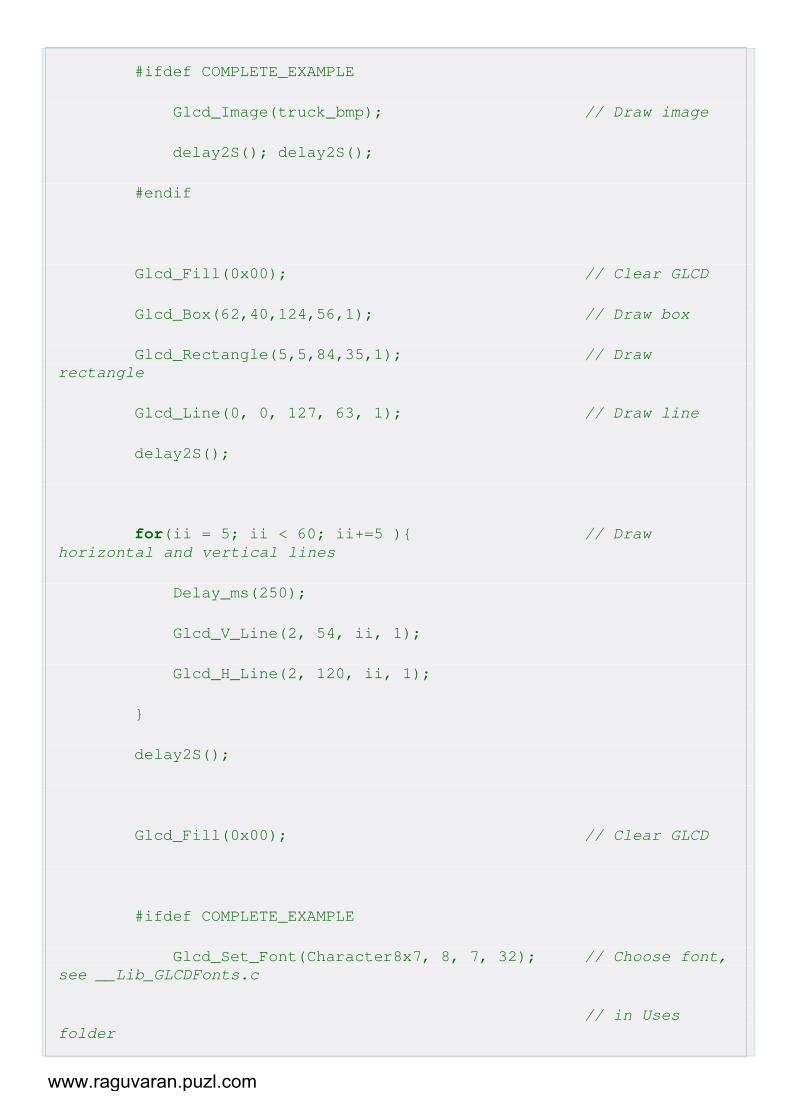
#ifdef COMPLETE_EXAMPLE
Glcd_Image(truck_bmp); // Draw image
delay2S(); delay2S();
#endif
Glcd_Fill(0x00); // Clear GLCD
Glcd_Box(62,40,124,56,1); // Draw box
Glcd_Rectangle(5,5,84,35,1); // Draw
rectangle
Glcd_Line(0, 0, 127, 63, 1); // Draw line
delay2S();
for(ii = 5; ii < 60; ii+=5 ) // Draw
horizontal and vertical lines
Delay_ms(250);
Glcd_V_Line(2, 54, ii, 1);
Glcd_H_Line(2, 120, ii, 1);
delay2S();
Glcd_Fill(0x00); // Clear GLCD
#ifdef COMPLETE_EXAMPLE
Glcd_Set_Font(Character8x7, 8, 7, 32); // Choose font,
see __Lib_GLCDFonts.c
// in Uses
folder
www.raguvaran.puzl.com
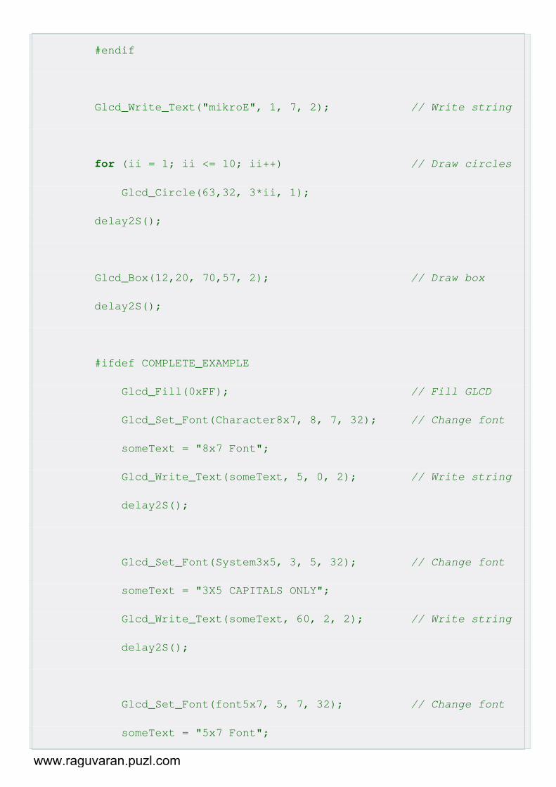
#endif
Glcd_Write_Text("mikroE", 1, 7, 2); // Write string
for (ii = 1; ii <= 10; ii++) // Draw circles
Glcd_Circle(63,32, 3*ii, 1);
delay2S();
Glcd_Box(12,20, 70,57, 2); // Draw box
delay2S();
#ifdef COMPLETE_EXAMPLE
Glcd_Fill(0xFF); // Fill GLCD
Glcd_Set_Font(Character8x7, 8, 7, 32); // Change font
someText = "8x7 Font";
Glcd_Write_Text(someText, 5, 0, 2); // Write string
delay2S();
Glcd_Set_Font(System3x5, 3, 5, 32); // Change font
someText = "3X5 CAPITALS ONLY";
Glcd_Write_Text(someText, 60, 2, 2); // Write string
delay2S();
Glcd_Set_Font(font5x7, 5, 7, 32); // Change font
someText = "5x7 Font";
www.raguvaran.puzl.com
Glcd_Write_Text(someText, 5, 4, 2); // Write string
delay2S();
Glcd_Set_Font(FontSystem5x7_v2, 5, 7, 32); // Change font
someText = "5x7 Font (v2)";
Glcd_Write_Text(someText, 5, 6, 2); // Write string
delay2S();
#endif
truck_bmp.c file:
// ------------------------------------------------------
// GLCD Picture name: truck.bmp
// GLCD Model: KS0108 128x64
// ------------------------------------------------------
unsigned char const truck_bmp[1024] =
0, 0, 0, 0, 0,248, 8, 8, 8, 8, 8, 8, 12, 12, 12, 12,
12, 10, 10, 10, 10, 10, 10, 9, 9, 9, 9, 9, 9, 9, 9, 9,
9, 9, 9, 9, 9, 9, 9, 9, 9, 9,137,137,137,137,137,137,
137,137,137,137,137,137,137, 9, 9, 9, 9, 9, 9, 9, 9, 9,
9, 9, 13,253, 13,195, 6,252, 0, 0, 0, 0, 0, 0, 0, 0,
0, 0, 0, 0, 0, 0, 0, 0, 0, 0, 0, 0, 0, 0, 0, 0,
0, 0, 0, 0, 0, 0, 0, 0, 0, 0, 0, 0, 0, 0, 0, 0,
www.raguvaran.puzl.com

0, 0, 0, 0, 0, 0, 0, 0, 0, 0, 0, 0, 0, 0, 0, 0,
0, 0, 0, 0, 0,255, 0, 0, 0, 0, 0, 0, 0, 0, 0, 0,
240,240,240,240,240,224,224,240,240,240,240,240,224,192,192,224,
240,240,240,240,240,224,192, 0, 0, 0,255,255,255,255,255,195,
195,195,195,195,195,195, 3, 0, 0, 0, 0, 0, 0, 0, 0, 0,
0, 0, 0,255,240, 79,224,255, 96, 96, 96, 32, 32, 32, 32, 32,
32, 32, 32, 32, 32, 32, 32, 32, 64, 64, 64, 64,128, 0, 0, 0,
0, 0, 0, 0, 0, 0, 0, 0, 0, 0, 0, 0, 0, 0, 0, 0,
0, 0, 0, 0, 0, 0, 0, 0, 0, 0, 0, 0, 0, 0, 0, 0,
0, 0, 0, 0, 0,255, 0, 0, 0, 0, 0, 0, 0, 0, 0, 0,
255,255,255,255,255, 0, 0, 0, 0,255,255,255,255,255, 0, 0,
0, 0,255,255,255,255,255, 0, 0, 0,255,255,255,255,255,129,
129,129,129,129,129,129,128, 0, 0, 0, 0, 0, 0, 0, 0, 0,
0, 0, 0,255, 1,248, 8, 8, 8, 8, 8, 8, 8, 8, 8, 8,
8, 8, 8, 8, 16,224, 24, 36,196, 70,130,130,133,217,102,112,
160,192, 96, 96, 32, 32,160,160,224,224,192, 64, 64,128,128,192,
64,128, 0, 0, 0, 0, 0, 0, 0, 0, 0, 0, 0, 0, 0, 0,
0, 0, 0, 0, 0, 63, 96, 96, 96,224, 96, 96, 96, 96, 96, 96,
99, 99, 99, 99, 99, 96, 96, 96, 96, 99, 99, 99, 99, 99, 96, 96,
96, 96, 99, 99, 99, 99, 99, 96, 96, 96, 99, 99, 99, 99, 99, 99,
99, 99, 99, 99, 99, 99, 99, 96, 96, 96, 96, 96, 96, 96, 64, 64,
64,224,224,255,246, 1, 14, 6, 6, 2, 2, 2, 2, 2, 2, 2,
2, 2, 2, 2,130, 67,114, 62, 35, 16, 16, 0, 7, 3, 3, 2,
4, 4, 4, 4, 4, 4, 4, 28, 16, 16, 16, 17, 17, 9, 9, 41,
112, 32, 67, 5,240,126,174,128, 56, 0, 0, 0, 0, 0, 0, 0,
www.raguvaran.puzl.com

0, 0, 0, 0, 0, 0, 0, 0, 0, 1, 1, 1, 1, 1, 1, 1,
1, 1,127,127,127,127,255,255,247,251,123,191, 95, 93,125,189,
189, 63, 93, 89,177,115,243,229,207, 27, 63,119,255,207,191,255,
255,255,255,255,255,255,255,127,127,127,127,127,127,127,127,255,
255,255,127,127,125,120,120,120,120,120,248,120,120,120,120,120,
120,248,248,232,143, 0, 0, 0, 0, 0, 0, 0, 0,128,240,248,
120,188,220, 92,252, 28, 28, 60, 92, 92, 60,120,248,248, 96,192,
143,168,216,136, 49, 68, 72, 50,160, 96, 0, 0, 0, 0, 0, 0,
0, 0, 0,128,192,248,248,248,248,252,254,254,254,254,254,254,
254,254,254,254,254,255,255,255,255,255,246,239,208,246,174,173,
169,128,209,208,224,247,249,255,255,252,220,240,127,255,223,255,
255,255,255,255,255,254,254,255,255,255,255,255,255,255,254,255,
255,255,255,255,255,255,254,254,254,254,254,254,254,254,254,254,
254,254,254,254,255,255,255,255,255,255,254,255,190,255,255,253,
240,239,221,223,254,168,136,170,196,208,228,230,248,127,126,156,
223,226,242,242,242,242,242,177, 32, 0, 0, 0, 0, 0, 0, 0,
0, 0, 0, 1, 1, 1, 1, 3, 3, 3, 7, 7, 7, 7, 7, 15,
15, 15, 7, 15, 15, 15, 7, 7, 15, 14, 15, 13, 15, 47, 43, 43,
43, 43, 43, 47,111,239,255,253,253,255,254,255,255,255,255,255,
191,191,239,239,239,191,255,191,255,255,255,255,255,255,255,255,
255,255,255,255,255,255,255,255,255,255,255,255,255,255,255,255,
255,255,255,255,127,127,127,127,255,255,191,191,191,191,255,254,
255,253,255,255,255,251,255,255,255,127,125, 63, 31, 31, 31, 31,
31, 31, 63, 15, 15, 7, 7, 3, 3, 3, 0, 0, 0, 0, 0, 0,
0, 0, 0, 0, 0, 0, 0, 0, 0, 0, 0, 0, 0, 0, 0, 0,
www.raguvaran.puzl.com
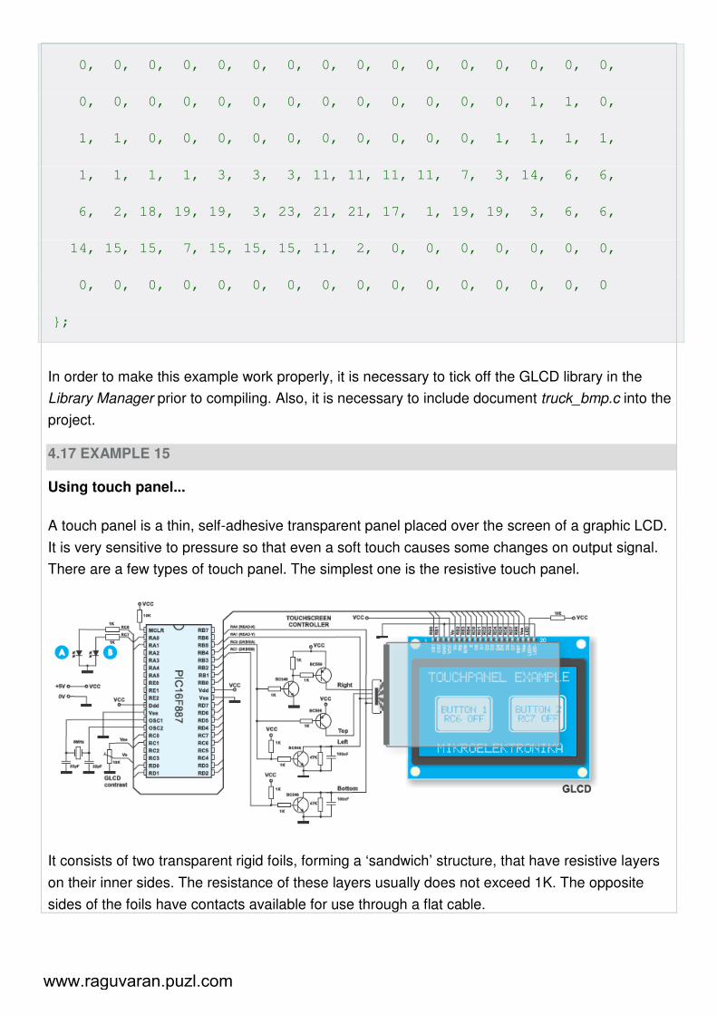
0, 0, 0, 0, 0, 0, 0, 0, 0, 0, 0, 0, 0, 0, 0, 0,
0, 0, 0, 0, 0, 0, 0, 0, 0, 0, 0, 0, 0, 1, 1, 0,
1, 1, 0, 0, 0, 0, 0, 0, 0, 0, 0, 0, 1, 1, 1, 1,
1, 1, 1, 1, 3, 3, 3, 11, 11, 11, 11, 7, 3, 14, 6, 6,
6, 2, 18, 19, 19, 3, 23, 21, 21, 17, 1, 19, 19, 3, 6, 6,
14, 15, 15, 7, 15, 15, 15, 11, 2, 0, 0, 0, 0, 0, 0, 0,
0, 0, 0, 0, 0, 0, 0, 0, 0, 0, 0, 0, 0, 0, 0, 0
;
In order to make this example work properly, it is necessary to tick off the GLCD library in the
Library Manager prior to compiling. Also, it is necessary to include document truck_bmp.c into the
project.
4.17 EXAMPLE 15
Using touch panel...
A touch panel is a thin, self-adhesive transparent panel placed over the screen of a graphic LCD.
It is very sensitive to pressure so that even a soft touch causes some changes on output signal.
There are a few types of touch panel. The simplest one is the resistive touch panel.
It consists of two transparent rigid foils, forming a ‘sandwich’ structure, that have resistive layers
on their inner sides. The resistance of these layers usually does not exceed 1K. The opposite
sides of the foils have contacts available for use through a flat cable.
www.raguvaran.puzl.com

The process of determining coordinates of the point in which the touch panel is pressed can be
broken up into two steps. The first one is the determination of the X coordinate and the second
one is the determination of the Y coordinate of the point.
In order to determine the X coordinate, it is necessary to connect the left contact on the surface A
to ground and the right contact to the power supply. This enables a voltage divider to be obtained
by pressing the touch panel. The value of the divider is read on the bottom contact of the surface
B. Voltage can be in the range of 0V to the power supply and depends on the X coordinate. If the
point is closer to the left contact of the surface A, the voltage will be closer to 0V.
In order to determine the Y coordinate, it is necessary to connect the bottom contact on the
surface B to ground, and the upper contact to power supply. In this case, the voltage is read on
the left contact of the surface A.
In order to connect a touch panel to the microcontroller it is necessary to create a circuit for touch
panel control. By means of this circuit, the microcontroller connects appropriate contacts of the
touch panel to ground and the power supply (as described above) in order to determine the X and
Y coordinates. The bottom contact of the surface B and left contact of the surface A are
connected to the microcontroller’s A/D converter. The X and Y coordinates are determined by
measuring voltage on these contacts, respectively. The software consists of writing a menu on
graphic LCD, turning the circuit for touch panel control on/off (driving touch panel) and reading the
values of A/D converter which actually represent the X and Y coordinates of the point.
Once the coordinates are determined, it is possible to decide what we want the microcontroller to
do. In this example, microcontroller turns on/off two digital pins, connected to LED diodes A and
B.
www.raguvaran.puzl.com
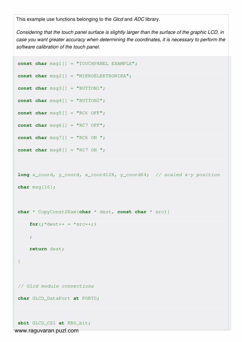
This example use functions belonging to the Glcd and ADC library.
Considering that the touch panel surface is slightly larger than the surface of the graphic LCD, in
case you want greater accuracy when determining the coordinates, it is necessary to perform the
software calibration of the touch panel.
const char msg1[] = "TOUCHPANEL EXAMPLE";
const char msg2[] = "MIKROELEKTRONIKA";
const char msg3[] = "BUTTON1";
const char msg4[] = "BUTTON2";
const char msg5[] = "RC6 OFF";
const char msg6[] = "RC7 OFF";
const char msg7[] = "RC6 ON ";
const char msg8[] = "RC7 ON ";
long x_coord, y_coord, x_coord128, y_coord64; // scaled x-y position
char msg[16];
char * CopyConst2Ram(char * dest, const char * src)
for(;*dest++ = *src++;)
;
return dest;
// Glcd module connections
char GLCD_DataPort at PORTD;
sbit GLCD_CS1 at RB0_bit;
www.raguvaran.puzl.com
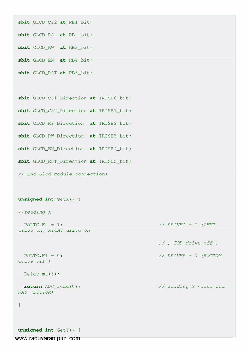
sbit GLCD_CS2 at RB1_bit;
sbit GLCD_RS at RB2_bit;
sbit GLCD_RW at RB3_bit;
sbit GLCD_EN at RB4_bit;
sbit GLCD_RST at RB5_bit;
sbit GLCD_CS1_Direction at TRISB0_bit;
sbit GLCD_CS2_Direction at TRISB1_bit;
sbit GLCD_RS_Direction at TRISB2_bit;
sbit GLCD_RW_Direction at TRISB3_bit;
sbit GLCD_EN_Direction at TRISB4_bit;
sbit GLCD_RST_Direction at TRISB5_bit;
// End Glcd module connections
unsigned int GetX()
//reading X
PORTC.F0 = 1; // DRIVEA = 1 (LEFT
drive on, RIGHT drive on
// , TOP drive off )
PORTC.F1 = 0; // DRIVEB = 0 (BOTTOM
drive off )
Delay_ms(5);
return ADC_read(0); // reading X value from
RA0 (BOTTOM)
unsigned int GetY()
www.raguvaran.puzl.com
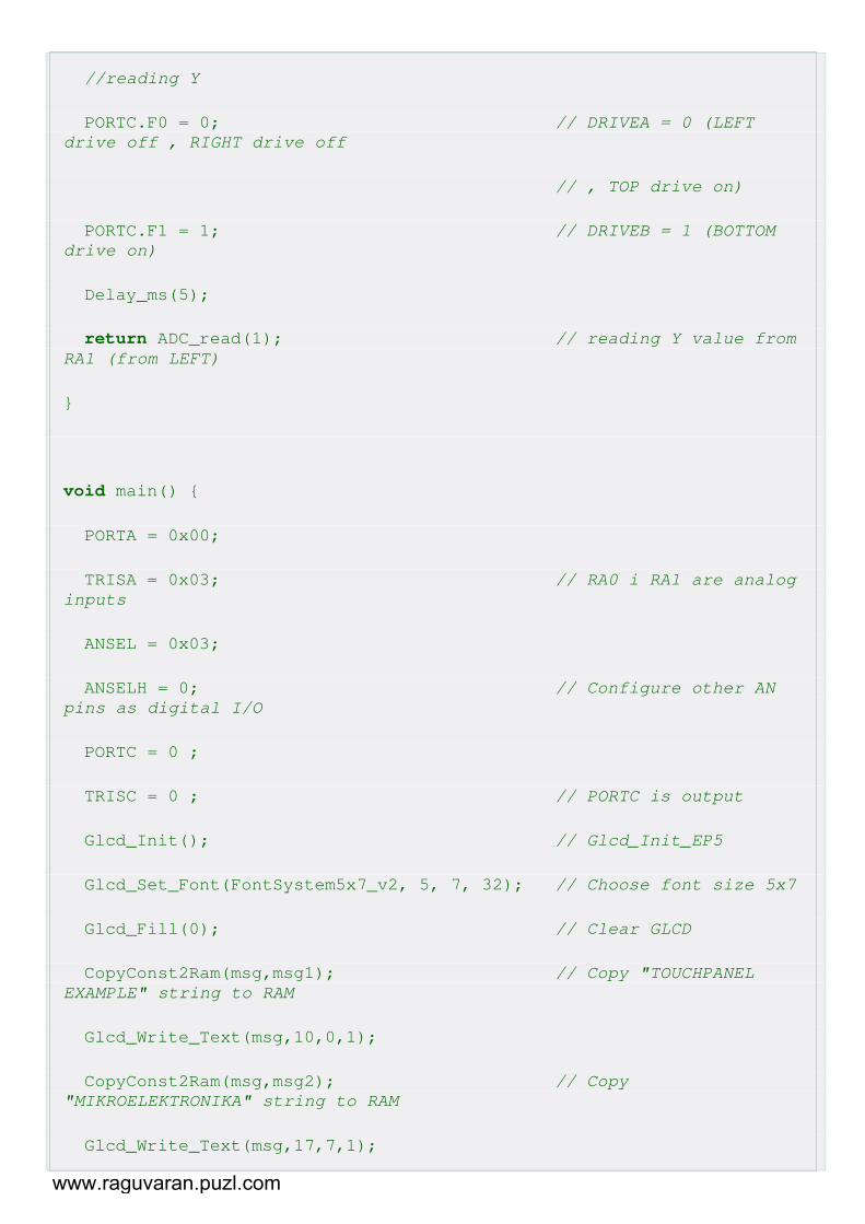
//reading Y
PORTC.F0 = 0; // DRIVEA = 0 (LEFT
drive off , RIGHT drive off
// , TOP drive on)
PORTC.F1 = 1; // DRIVEB = 1 (BOTTOM
drive on)
Delay_ms(5);
return ADC_read(1); // reading Y value from
RA1 (from LEFT)
void main()
PORTA = 0x00;
TRISA = 0x03; // RA0 i RA1 are analog
inputs
ANSEL = 0x03;
ANSELH = 0; // Configure other AN
pins as digital I/O
PORTC = 0 ;
TRISC = 0 ; // PORTC is output
Glcd_Init(); // Glcd_Init_EP5
Glcd_Set_Font(FontSystem5x7_v2, 5, 7, 32); // Choose font size 5x7
Glcd_Fill(0); // Clear GLCD
CopyConst2Ram(msg,msg1); // Copy "TOUCHPANEL
EXAMPLE" string to RAM
Glcd_Write_Text(msg,10,0,1);
CopyConst2Ram(msg,msg2); // Copy
"MIKROELEKTRONIKA" string to RAM
Glcd_Write_Text(msg,17,7,1);
www.raguvaran.puzl.com
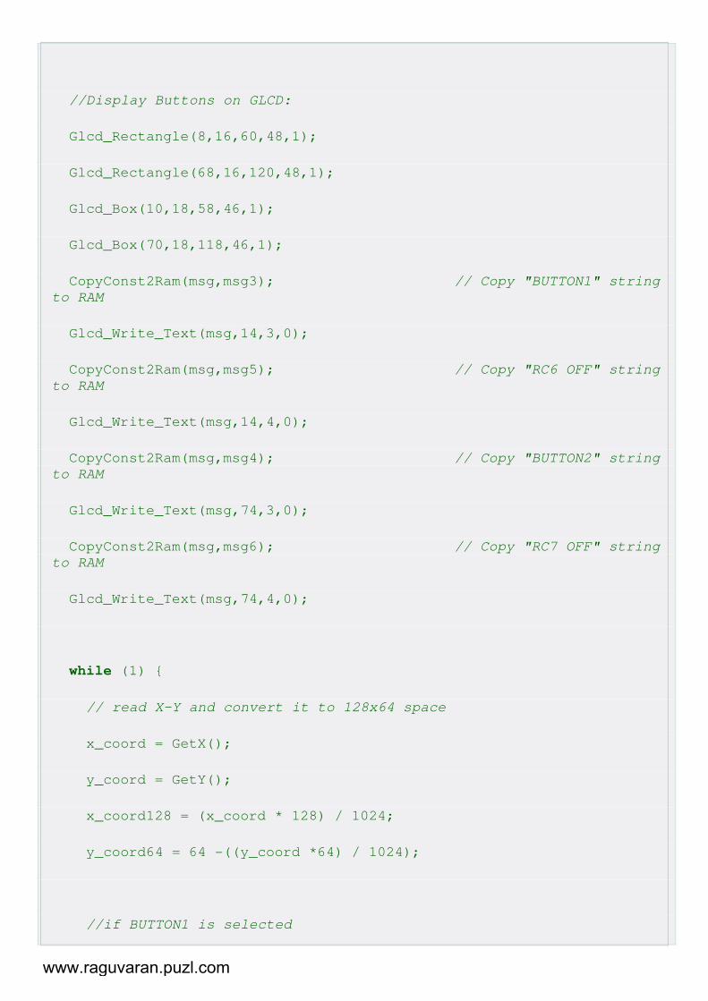
//Display Buttons on GLCD:
Glcd_Rectangle(8,16,60,48,1);
Glcd_Rectangle(68,16,120,48,1);
Glcd_Box(10,18,58,46,1);
Glcd_Box(70,18,118,46,1);
CopyConst2Ram(msg,msg3); // Copy "BUTTON1" string
to RAM
Glcd_Write_Text(msg,14,3,0);
CopyConst2Ram(msg,msg5); // Copy "RC6 OFF" string
to RAM
Glcd_Write_Text(msg,14,4,0);
CopyConst2Ram(msg,msg4); // Copy "BUTTON2" string
to RAM
Glcd_Write_Text(msg,74,3,0);
CopyConst2Ram(msg,msg6); // Copy "RC7 OFF" string
to RAM
Glcd_Write_Text(msg,74,4,0);
while (1)
// read X-Y and convert it to 128x64 space
x_coord = GetX();
y_coord = GetY();
x_coord128 = (x_coord * 128) / 1024;
y_coord64 = 64 -((y_coord *64) / 1024);
//if BUTTON1 is selected
www.raguvaran.puzl.com
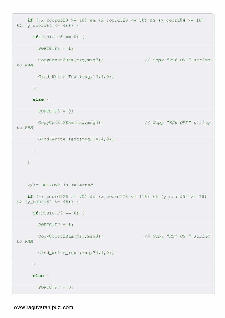
if ((x_coord128 >= 10) && (x_coord128 <= 58) && (y_coord64 >= 18)
&& (y_coord64 <= 46))
if(PORTC.F6 == 0)
PORTC.F6 = 1;
CopyConst2Ram(msg,msg7); // Copy "RC6 ON " string
to RAM
Glcd_Write_Text(msg,14,4,0);
else
PORTC.F6 = 0;
CopyConst2Ram(msg,msg5); // Copy "RC6 OFF" string
to RAM
Glcd_Write_Text(msg,14,4,0);
//if BUTTON2 is selected
if ((x_coord128 >= 70) && (x_coord128 <= 118) && (y_coord64 >= 18)
&& (y_coord64 <= 46))
if(PORTC.F7 == 0)
PORTC.F7 = 1;
CopyConst2Ram(msg,msg8); // Copy "RC7 ON " string
to RAM
Glcd_Write_Text(msg,74,4,0);
else
PORTC.F7 = 0;
www.raguvaran.puzl.com

CopyConst2Ram(msg,msg6); // Copy "RC7 OFF" string
to RAM
Glcd_Write_Text(msg,74,4,0);
Delay_ms(100);
In order to make this example work properly, it is necessary to tick off the following libraries in the
Library Manager prior to compiling:
• GLCD • ADC • C_Stdlib
Appendix A: It’s Time for Fun
A microcontroller is a good-natured ‘genie in the bottle’ and no extra knowledge is required to use
it. In order to create a device controlled by the microcontroller, it is necessary to provide the
simplest PC, program for compiling and simple device to transfer code from PC to the chip itself.
Even though this process is quite logical, there are often some queries, not because it is
complicated, but for numerous variations. Let’s take a look.
• A.1 LET'S BEGIN... • A.2 PROGRAM COMPILATION • A.3 IS THIS A HAPPY ENDING? • A.4 DEVELOPMENT SYSTEMS
A.1 LET'S BEGIN...
Specialized programs in the Windows environment are used for writing a program for the
microcontroller. This book describes one of them called mikroC PRO for PIC. The main
advantage of this program is that it features many additional tools installed to aid in the
development process.
If you have experience with program writing then you know that the point is to write all instructions
in such an order they should be executed by the microcontroller and observe the rules of C
language. In other words, the program you are writing just has to follow your idea! That’s all!
www.raguvaran.puzl.com
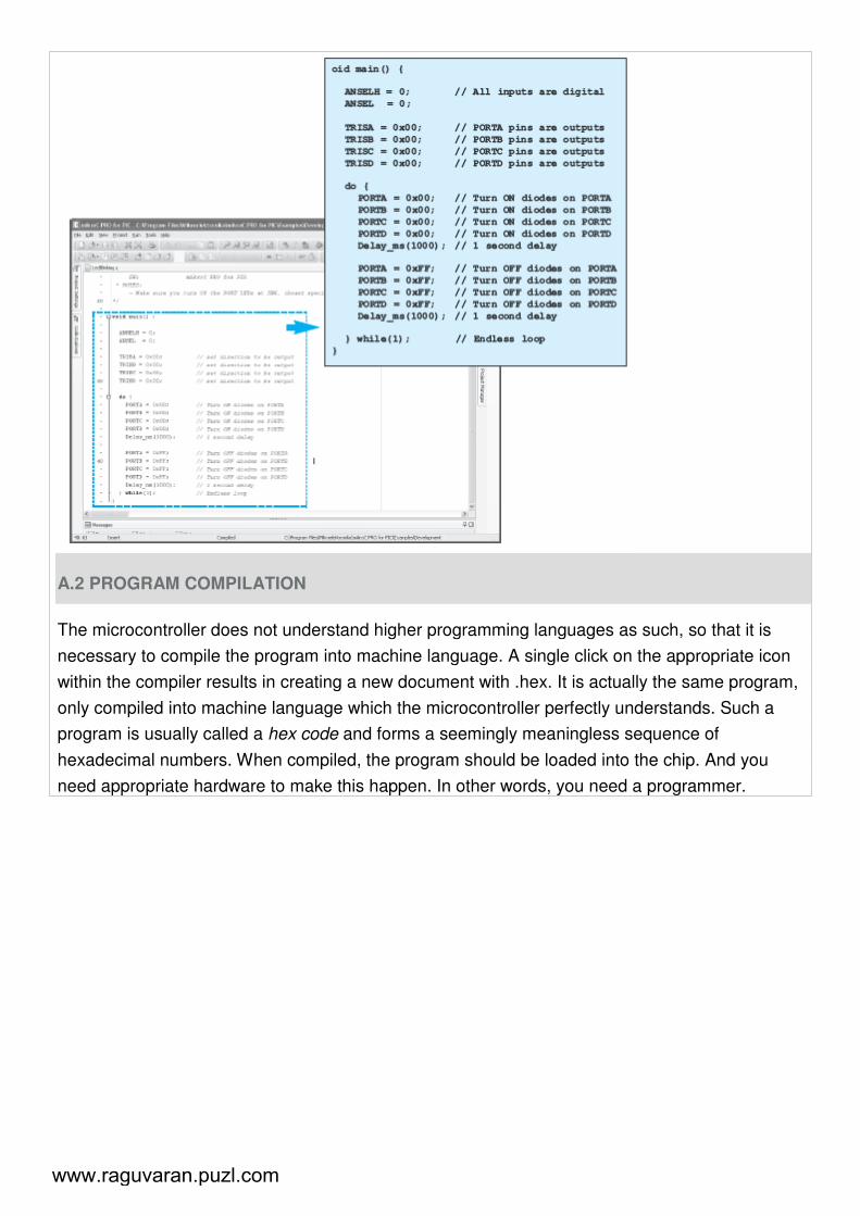
A.2 PROGRAM COMPILATION
The microcontroller does not understand higher programming languages as such, so that it is
necessary to compile the program into machine language. A single click on the appropriate icon
within the compiler results in creating a new document with .hex. It is actually the same program,
only compiled into machine language which the microcontroller perfectly understands. Such a
program is usually called a hex code and forms a seemingly meaningless sequence of
hexadecimal numbers. When compiled, the program should be loaded into the chip. And you
need appropriate hardware to make this happen. In other words, you need a programmer.
www.raguvaran.puzl.com
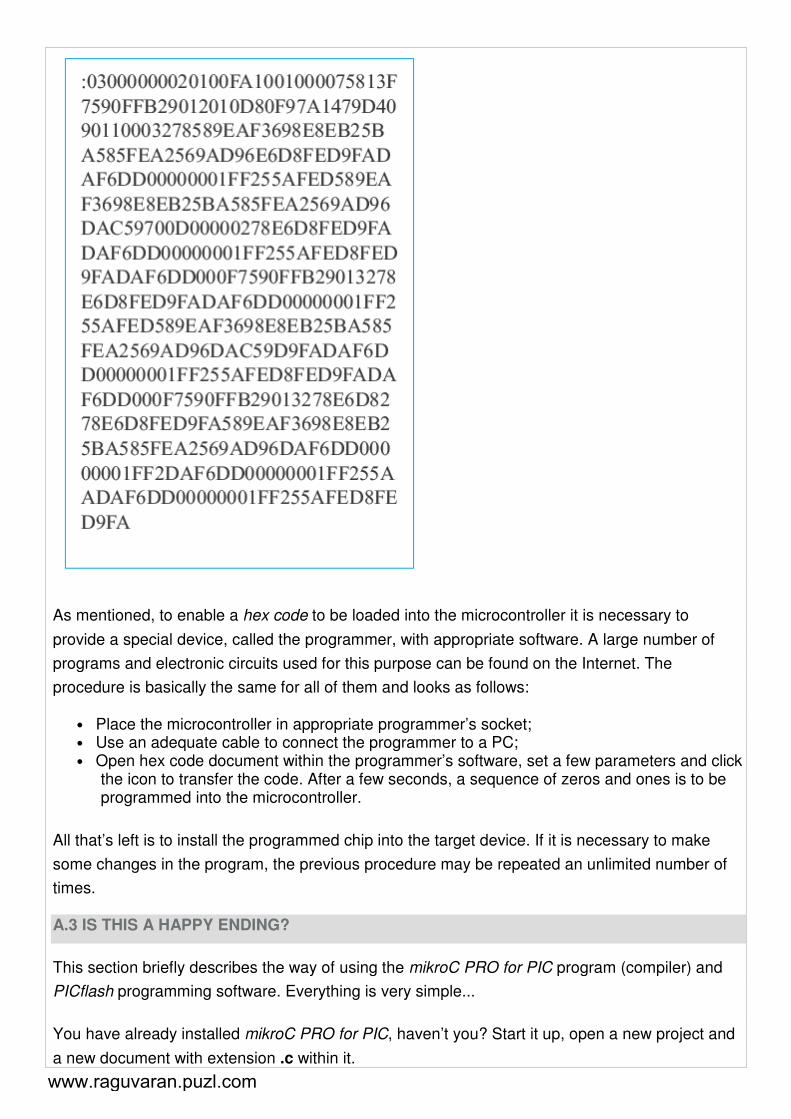
As mentioned, to enable a hex code to be loaded into the microcontroller it is necessary to
provide a special device, called the programmer, with appropriate software. A large number of
programs and electronic circuits used for this purpose can be found on the Internet. The
procedure is basically the same for all of them and looks as follows:
• Place the microcontroller in appropriate programmer’s socket; • Use an adequate cable to connect the programmer to a PC; • Open hex code document within the programmer’s software, set a few parameters and click
the icon to transfer the code. After a few seconds, a sequence of zeros and ones is to be programmed into the microcontroller.
All that’s left is to install the programmed chip into the target device. If it is necessary to make
some changes in the program, the previous procedure may be repeated an unlimited number of
times.
A.3 IS THIS A HAPPY ENDING?
This section briefly describes the way of using the mikroC PRO for PIC program (compiler) and
PICflash programming software. Everything is very simple...
You have already installed mikroC PRO for PIC, haven’t you? Start it up, open a new project and
a new document with extension .c within it.
www.raguvaran.puzl.com
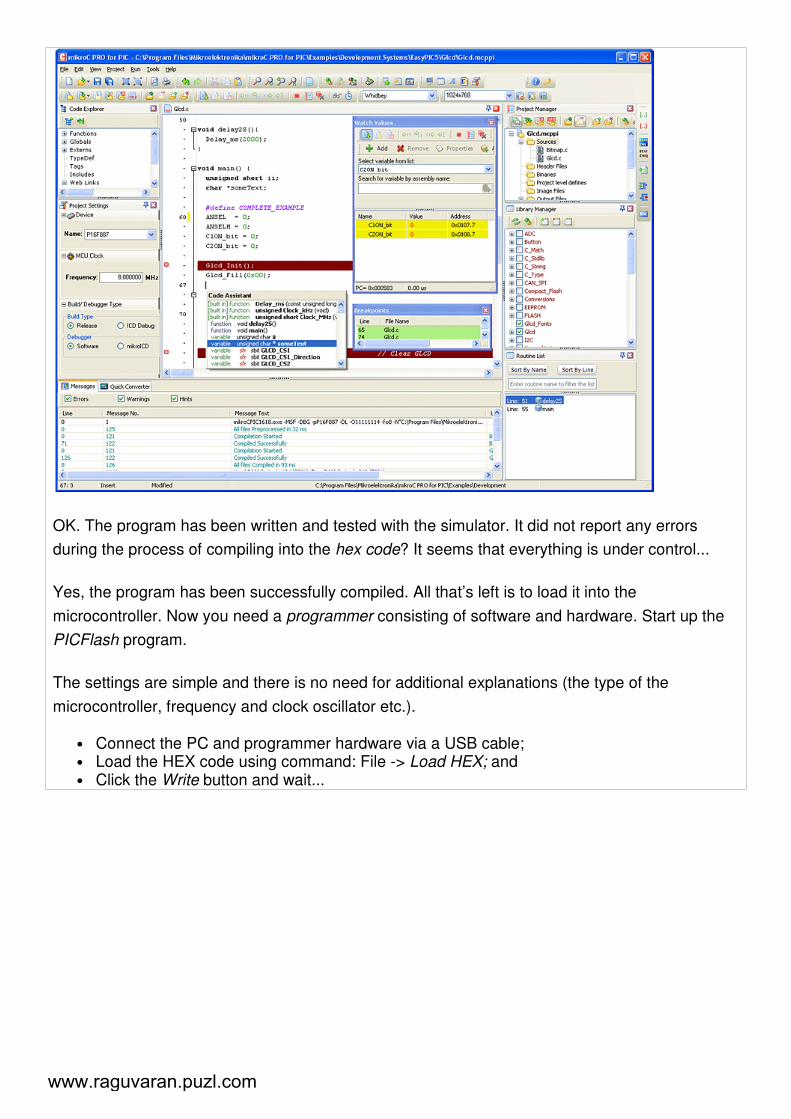
OK. The program has been written and tested with the simulator. It did not report any errors
during the process of compiling into the hex code? It seems that everything is under control...
Yes, the program has been successfully compiled. All that’s left is to load it into the
microcontroller. Now you need a programmer consisting of software and hardware. Start up the
PICFlash program.
The settings are simple and there is no need for additional explanations (the type of the
microcontroller, frequency and clock oscillator etc.).
• Connect the PC and programmer hardware via a USB cable; • Load the HEX code using command: File -> Load HEX; and • Click the Write button and wait...
www.raguvaran.puzl.com
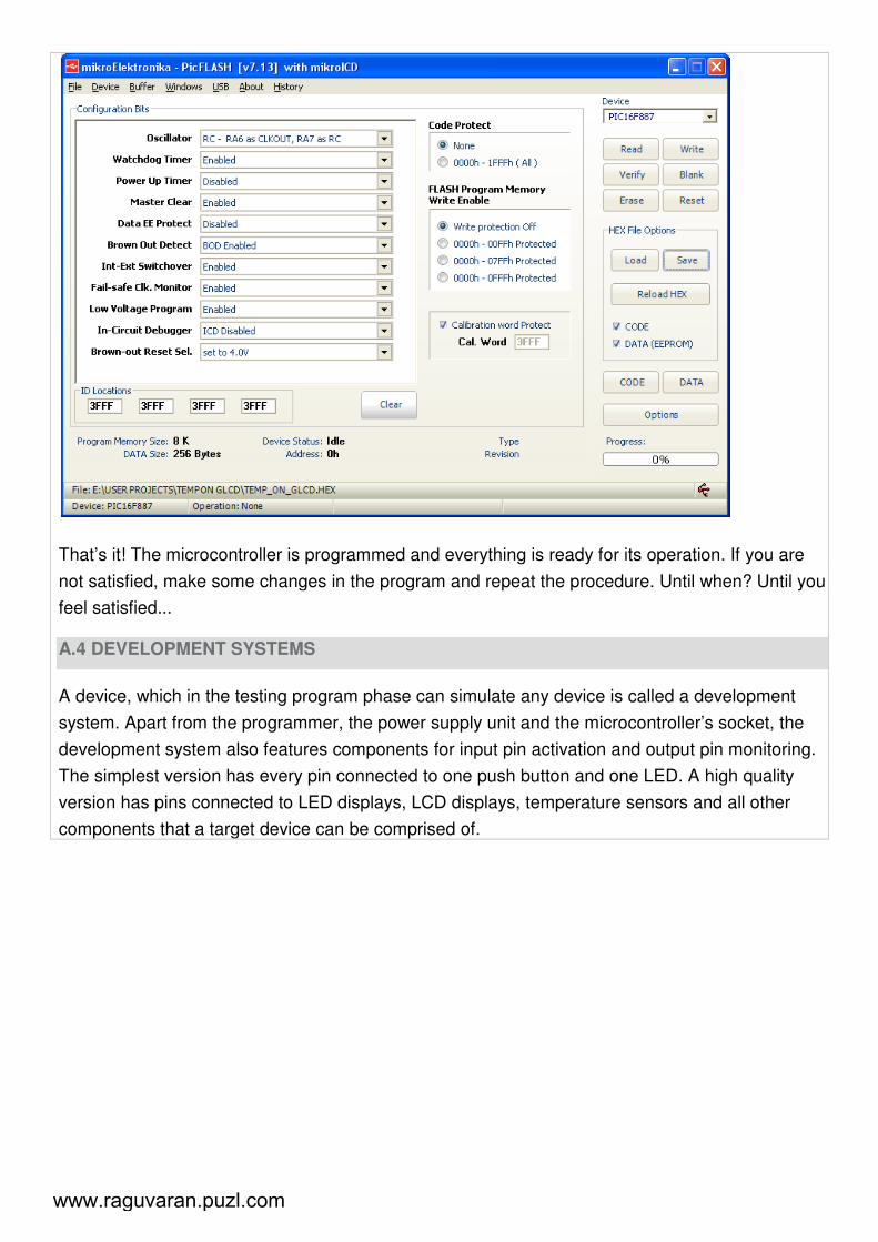
That’s it! The microcontroller is programmed and everything is ready for its operation. If you are
not satisfied, make some changes in the program and repeat the procedure. Until when? Until you
feel satisfied...
A.4 DEVELOPMENT SYSTEMS
A device, which in the testing program phase can simulate any device is called a development
system. Apart from the programmer, the power supply unit and the microcontroller’s socket, the
development system also features components for input pin activation and output pin monitoring.
The simplest version has every pin connected to one push button and one LED. A high quality
version has pins connected to LED displays, LCD displays, temperature sensors and all other
components that a target device can be comprised of.
www.raguvaran.puzl.com
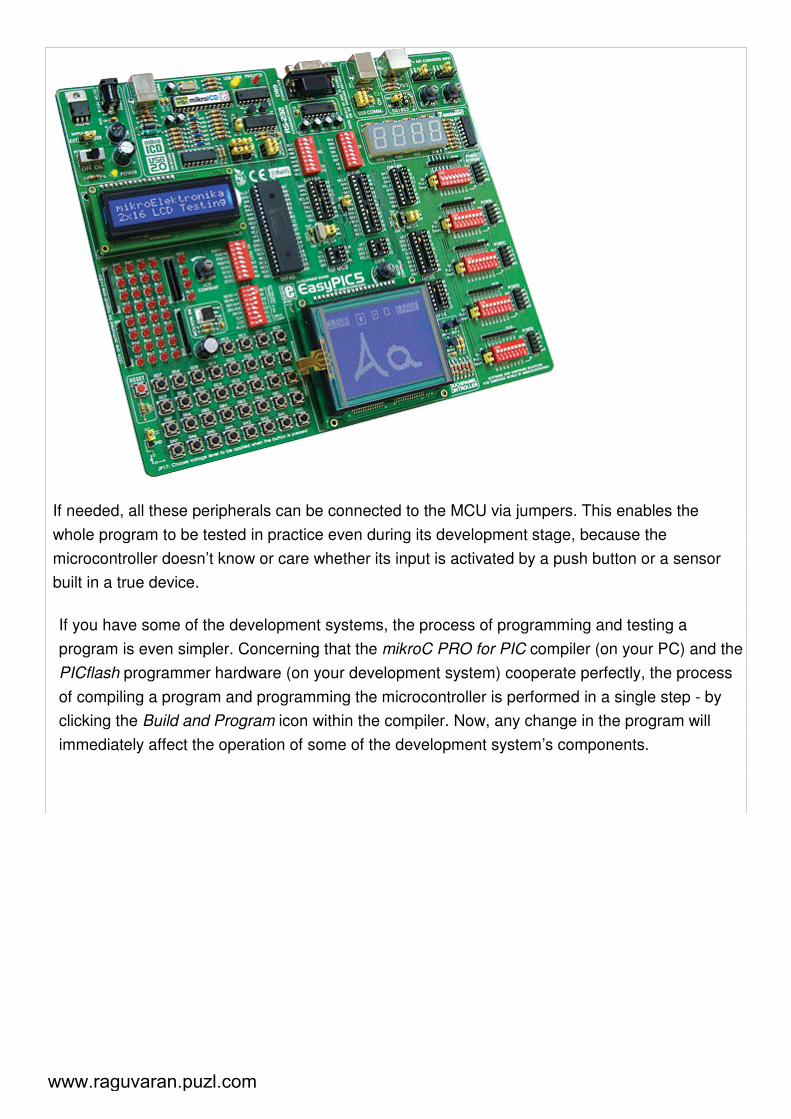
If needed, all these peripherals can be connected to the MCU via jumpers. This enables the
whole program to be tested in practice even during its development stage, because the
microcontroller doesn’t know or care whether its input is activated by a push button or a sensor
built in a true device.
If you have some of the development systems, the process of programming and testing a
program is even simpler. Concerning that the mikroC PRO for PIC compiler (on your PC) and the
PICflash programmer hardware (on your development system) cooperate perfectly, the process
of compiling a program and programming the microcontroller is performed in a single step - by
clicking the Build and Program icon within the compiler. Now, any change in the program will
immediately affect the operation of some of the development system’s components.
www.raguvaran.puzl.com
Related Documents