RS08 Microcontrollers freescale.com Piano and Dimming Light Using Ultra Low-End MCU and Electric-Field Sensor Designer Reference Manual DRM085 Rev. 0 10/2006

Welcome message from author
This document is posted to help you gain knowledge. Please leave a comment to let me know what you think about it! Share it to your friends and learn new things together.
Transcript
RS08Microcontrollers
freescale.com
Piano and Dimming Light Using Ultra Low-End MCU and Electric-Field SensorDesigner Reference Manual
DRM085Rev. 010/2006


Piano and Dimming Light Using Ultra Low-End MCU and Electric-Field SensorDesigner Reference Manual
by: Ulises Corrales Manuel Davalos Allan Led Collins
RTAC Americas
Mexico
Piano and Dimming Light Using Ultra Low-End MCU and E-Field Sensor, Rev. 0, Draft A. 09/2006
Freescale Semiconductor 3
Revision History
To provide the most up-to-date information, the revision of our documents on the World Wide Web will be the most current. Your printed copy may be an earlier revision. To verify that you have the latest information available, refer to http://www.freescale.com
The following revision history table summarizes changes contained in this document. For your convenience, the page number designators are linked to the appropriate location.
Revision History
DateRevision
LevelDescription
PageNumber(s)
07/2006 0 Initial release N/A
Piano and Dimming Light Using Ultra Low-End MCU and E-Field Sensor, Rev. 0, Draft A. 09/2006
4 Freescale Semiconductor

Chapter 1 Designer Reference Manual Usage Notes
1.1 Intended Application Functionality . . . . . . . . . . . . . . . . . . . . . . . . . . . . . . . . . . . . . . . . . . . . . . . . 71.2 Quick Start . . . . . . . . . . . . . . . . . . . . . . . . . . . . . . . . . . . . . . . . . . . . . . . . . . . . . . . . . . . . . . . . . . 71.2.1 System Requirements . . . . . . . . . . . . . . . . . . . . . . . . . . . . . . . . . . . . . . . . . . . . . . . . . . . . . . 71.2.2 MC9RS08KA2 PADL Setup . . . . . . . . . . . . . . . . . . . . . . . . . . . . . . . . . . . . . . . . . . . . . . . . . . 7
Chapter 2 Hardware Description
2.1 Introduction . . . . . . . . . . . . . . . . . . . . . . . . . . . . . . . . . . . . . . . . . . . . . . . . . . . . . . . . . . . . . . . . 112.1.1 Piano Function . . . . . . . . . . . . . . . . . . . . . . . . . . . . . . . . . . . . . . . . . . . . . . . . . . . . . . . . . . . 112.1.2 Dimmer Light Function . . . . . . . . . . . . . . . . . . . . . . . . . . . . . . . . . . . . . . . . . . . . . . . . . . . . . 122.2 Technical Data . . . . . . . . . . . . . . . . . . . . . . . . . . . . . . . . . . . . . . . . . . . . . . . . . . . . . . . . . . . . . . 122.2.1 MC9RS08KA2 Microcontroller Unit . . . . . . . . . . . . . . . . . . . . . . . . . . . . . . . . . . . . . . . . . . . 122.2.2 Electrical-Field Imaging Device (MC34940). . . . . . . . . . . . . . . . . . . . . . . . . . . . . . . . . . . . . 132.3 MC9RS08KA2 PADL Reference Design Architecture . . . . . . . . . . . . . . . . . . . . . . . . . . . . . . . . 132.3.1 MC9RS08KA2 . . . . . . . . . . . . . . . . . . . . . . . . . . . . . . . . . . . . . . . . . . . . . . . . . . . . . . . . . . . 132.3.2 Electrical Field (MC34940). . . . . . . . . . . . . . . . . . . . . . . . . . . . . . . . . . . . . . . . . . . . . . . . . . 132.4 Board Layout . . . . . . . . . . . . . . . . . . . . . . . . . . . . . . . . . . . . . . . . . . . . . . . . . . . . . . . . . . . . . . . 142.4.1 PADL Components Board . . . . . . . . . . . . . . . . . . . . . . . . . . . . . . . . . . . . . . . . . . . . . . . . . . 152.4.2 General Layout Explanation. . . . . . . . . . . . . . . . . . . . . . . . . . . . . . . . . . . . . . . . . . . . . . . . . 152.4.3 PCB Board Size . . . . . . . . . . . . . . . . . . . . . . . . . . . . . . . . . . . . . . . . . . . . . . . . . . . . . . . . . . 152.4.4 Component Placement. . . . . . . . . . . . . . . . . . . . . . . . . . . . . . . . . . . . . . . . . . . . . . . . . . . . . 152.4.5 Layout Layers. . . . . . . . . . . . . . . . . . . . . . . . . . . . . . . . . . . . . . . . . . . . . . . . . . . . . . . . . . . . 16
Chapter 3 Firmware Description
3.1 Introduction . . . . . . . . . . . . . . . . . . . . . . . . . . . . . . . . . . . . . . . . . . . . . . . . . . . . . . . . . . . . . . . . 193.1.1 Firmware Basics. . . . . . . . . . . . . . . . . . . . . . . . . . . . . . . . . . . . . . . . . . . . . . . . . . . . . . . . . . 193.1.2 Application Basics . . . . . . . . . . . . . . . . . . . . . . . . . . . . . . . . . . . . . . . . . . . . . . . . . . . . . . . . 193.2 Project Introduction . . . . . . . . . . . . . . . . . . . . . . . . . . . . . . . . . . . . . . . . . . . . . . . . . . . . . . . . . . 193.2.1 Coding Convention. . . . . . . . . . . . . . . . . . . . . . . . . . . . . . . . . . . . . . . . . . . . . . . . . . . . . . . . 193.2.2 List of Project Files. . . . . . . . . . . . . . . . . . . . . . . . . . . . . . . . . . . . . . . . . . . . . . . . . . . . . . . . 193.2.3 MCU Peripherals . . . . . . . . . . . . . . . . . . . . . . . . . . . . . . . . . . . . . . . . . . . . . . . . . . . . . . . . . 193.2.4 Software Interrupts. . . . . . . . . . . . . . . . . . . . . . . . . . . . . . . . . . . . . . . . . . . . . . . . . . . . . . . . 203.2.5 Main Variables of the Project . . . . . . . . . . . . . . . . . . . . . . . . . . . . . . . . . . . . . . . . . . . . . . . . 213.2.6 Memory Usage. . . . . . . . . . . . . . . . . . . . . . . . . . . . . . . . . . . . . . . . . . . . . . . . . . . . . . . . . . . 213.3 Firmware Implementation . . . . . . . . . . . . . . . . . . . . . . . . . . . . . . . . . . . . . . . . . . . . . . . . . . . . . 213.3.1 Application . . . . . . . . . . . . . . . . . . . . . . . . . . . . . . . . . . . . . . . . . . . . . . . . . . . . . . . . . . . . . . 21
Appendix A BOM and Schematics
Appendix B Glossary
Piano and Dimming Light Using Ultra Low-End MCU and Electric-Field Sesnsor, Rev. 0
Freescale Semiconductor 5

Piano and Dimming Light Using Ultra Low-End MCU and Electric-Field Sesnsor
6 Freescale Semiconductor

Chapter 1 Designer Reference Manual Usage Notes
1.1 Intended Application Functionality
This reference design demonstrates the application of Freescale’s MC9RS08KA2 microcontroller and the MC34940 electrical field. This demonstration shows the connection between MC9RS08KA2 and the electrical-field sensor.
This demonstration can play seven musical notes (C, D, E, F, G, A, B) and be heard in a buzzer. A switch can change a piano function to a dimmer-light function with one electrode divided into five parts of varying intensity. One electrode connects to the electrical field when the demonstration works on a dimmer function. When the demonstration works in piano function, the electrical field is connected to seven electrodes.
The MC9RS08KA2 PADL reference design is intended for the toy industry and for use in some lighting devices (for example, lamps).
1.2 Quick Start
The demonstration shows the connection between the MC9RS08KA2 ultra low-end, 8-bit microcontroller and the MC34940, an electrical-field imaging device.
1.2.1 System Requirements
This demonstration needs only a 12 V DC external power supply to work properly.
1.2.2 MC9RS08KA2 PADL Setup
The MC9RS08KA2 PADL demonstration requires no setup. The board is distributed with the application loaded in the MC9RS08KA2 flash memory. Changing between functions depends on the switch position. Figure 1-1 and Figure 1-2 are pictures of the reference design board.
Piano and Dimming Light Using Ultra Low-End MCU and E-Field Sensor, Rev. 0
Freescale Semiconductor 7Subject to Change Without Notice

Designer Reference Manual Usage Notes
Figure 1-1. MC9RS08KA2 PADL Board (Front)
Figure 1-2. MC9RS08KA2 PADL Board (Back)1. Switch — Selects between piano and dimmer light.2. BDM connector3. Power supply4. Buzzer5. Dimmer electrodes6. Piano electrodes
1. 2. 3.4.
5.
6.
Piano and Dimming Light Using Ultra Low-End MCU and E-Field Sensor, Rev. 0
8 Freescale SemiconductorSubject to Change Without Notice
To run the demonstration:1. Put the switch in position 1 or position 2.
a. Position 1 selects dimming mode.
b. Position 2 selects piano mode.
2. Connect the 12 V DC power supply to the demo board.3. Start pressing the electrodes.
Piano and Dimming Light Using Ultra Low-End MCU and E-Field Sensor, Rev. 0
Freescale Semiconductor 9Subject to Change Without Notice

Designer Reference Manual Usage Notes
Piano and Dimming Light Using Ultra Low-End MCU and E-Field Sensor, Rev. 0
10 Freescale SemiconductorSubject to Change Without Notice
Chapter 2 Hardware Description
2.1 Introduction
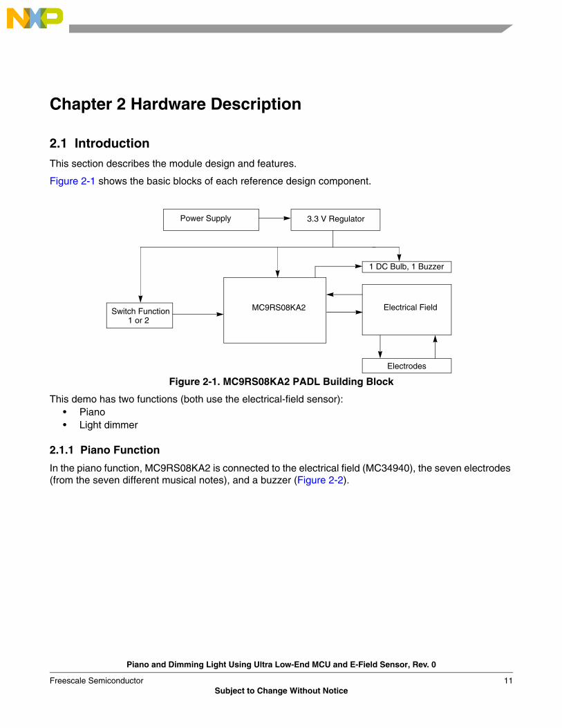
This section describes the module design and features.
Figure 2-1 shows the basic blocks of each reference design component.
Figure 2-1. MC9RS08KA2 PADL Building Block
This demo has two functions (both use the electrical-field sensor):• Piano • Light dimmer
2.1.1 Piano Function
In the piano function, MC9RS08KA2 is connected to the electrical field (MC34940), the seven electrodes (from the seven different musical notes), and a buzzer (Figure 2-2).
Power Supply 3.3 V Regulator
1 DC Bulb, 1 Buzzer
MC9RS08KA2 Electrical Field
Electrodes
Switch Function1 or 2
Piano and Dimming Light Using Ultra Low-End MCU and E-Field Sensor, Rev. 0
Freescale Semiconductor 11Subject to Change Without Notice

Hardware Description
Figure 2-2. MC9RS08KA2 PADL Function 1 Logic Diagram
2.1.2 Dimmer Light Function
When the demo runs in dimmer light function, the MC9RS08KA2 MCU is connected to an electrical field and DC bulb. The electrical field is also connected to a divided electrode. Figure 2-3 shows the logic block diagram for function 2.
Figure 2-3. MC9RS08KA2 PADL Function 2 Logic Diagram
2.2 Technical Data
This section provides technical details of the MC9RS08KA2 PADL and components in this reference design.
2.2.1 MC9RS08KA2 Microcontroller Unit
The MC9RS08KA2 is the control unit for the PADL and part of the RS08 family.
MC9RS08KA2 features:• 8-bit RS08 CPU
– Analog comparator (ACMP)
ABC
Level
B
A
G
F
EDC
E7
E6
E5
E4
E3
E2
E1
Buzzer
Power Stage
MC9RS08KA2
MC34940
Shield
A
Level E1
Power Stage
MC9RS08KA2
Shield
DC Bulb
MC34940
Piano and Dimming Light Using Ultra Low-End MCU and E-Field Sensor, Rev. 0
12 Freescale SemiconductorSubject to Change Without Notice
MC9RS08KA2 PADL Reference Design Architecture
– Keyboard interrupt (KBI)– Pending interrupt indication– Background debug mode (BDM)
• Reset, clock, COP watchdog• 6-bit port with digital filtering and programmable rising- or falling-edge trigger• Memory
– 2K flash EEPROM– 63 bytes RAM
MC9RS08KA2 functions:• Controls the MC34940 (electrical field)• Generates the pulse width modulation (PWM) for the dimming light and musical notes• Switches between PADL functions• Processes data
2.2.2 Electrical-Field Imaging Device (MC34940)MC34940 is a sensor that detects objects in an electrical field. In this demonstration, it detects the user’s hands.
Features:• Supports up to nine electrodes and two references or electrodes• Shield driver for driving remote electrodes through coaxial cables• Lamp driver output• Watchdog and power-on reset timer• High-purity sine wave generator tunable with external resistor
Function:• Relays electrode status to microcontroller
2.3 MC9RS08KA2 PADL Reference Design Architecture
2.3.1 MC9RS08KA2
The MC9RS08KA2 controls the application.
The application occupies these modules:• General-purpose input/output pins (GPIO)• Analog comparator (ACMP)• Modulo timer (MTIM)
2.3.2 Electrical Field (MC34940)
The MC34940 generates a low radio frequency sine wave with nominal 5 V peak-to-peak amplitude. An internal multiplexer routes the signal to one of seven terminals under the ABC input terminals. A receiver multiplexer connected to the selected electrode simultaneously routes its signal to a detector that converts the sine wave to a DC level. The DC level is filtered by an external capacitor, and that value is multiplied so the value offset is less sensitive to objects near the signal.
Piano and Dimming Light Using Ultra Low-End MCU and E-Field Sensor, Rev. 0
Freescale Semiconductor 13

Hardware Description
trodesh E7)
A capacitor is formed between the driving electrode and the object, each forming a plate that holds the electrical charge. The voltage measured is an inverse function of the capacitance among the electrode being measured, the surrounding electrodes, and other objects in the electrical field surrounding the electrode. Increasing capacitance decreases voltage.
The basic building block for these devices is found in Figure 2-4 and shows its connections and functionality, the shield module, and the electrode select.
Figure 2-4. Electrical-Field Building Block
2.4 Board Layout
The detailed layout, schematic, and bill of materials (BOM) of the MC9RS08KA2 PADL reference design are shown in this section.
MC34940
VCCCAP
VDDCAP
10 nF
47 μF
47 μF
39 kΩ
LPCAP
ROSC
LEVEL
A, B, C
SHIELDEN
VPWR
TEST
AGND
GND
MCU
3
Analog In
Electrode Select
Shield Enable
+12 V
Field Elec(E1 throug
E1
E7
Piano and Dimming Light Using Ultra Low-End MCU and E-Field Sensor, Rev. 0
14 Freescale SemiconductorSubject to Change Without Notice

2.4.1 PADL Components Board
Figure 2-5. PADL Component Side
2.4.2 General Layout Explanation
The circuit board layout considerations are dominated by:• Minimizing size• The need to conduct high currents into the module, to the power drivers, and then out of the module
2.4.3 PCB Board Size
The circuit board size is 7.1 x 3.8 inches.
2.4.4 Component Placement
Before laying out the PCB, components were placed on the PCB. Figure 2-6 shows the separated main blocks. Low-level analog, digital circuitry, and high-current switches were separated to maintain signal integrity.
Figure 2-6. PADL Board and Main Blocks
Light Bulband
Buzzer
PowerSupply
Switch
Electrical Field
Op Amps
PowerSurge
Piano and Light Dimmer Electrodes
MC9RS08KA2
Piano and Dimming Light Using Ultra Low-End MCU and E-Field Sensor, Rev. 0
Freescale Semiconductor 15Subject to Change Without Notice

Hardware Description
• BDM Connector—Near the MC9RS08KA2 microcontroller.• Power Stage Block—Digital devices are separated from the high-current management blocks. • Electrical-Field Footprints—Electrodes must be near the electrical-field electrodes to avoid
parasite capacitance.• Via Dimensions and Spacing—Electrode spacing is 244 mil. The electrode width is 636 mil, and
the electrode height is 1476 mil. The vias spacing is 35 mil.
2.4.5 Layout Layers
2.4.5.1 Top Layer
The low-analog and digital signals are separated from battery and high current traces to avoid interference between the signals; the signals from the piano and dimmer electrodes are near the electrical-field device.
Figure 2-7. Top Layer
2.4.5.2 Bottom Layer
Similar to the top layer, the low-analog and digital signals are separated from battery and high current traces to avoid interference between the signals (Figure 2-8).
Piano and Dimming Light Using Ultra Low-End MCU and E-Field Sensor, Rev. 0
16 Freescale SemiconductorSubject to Change Without Notice
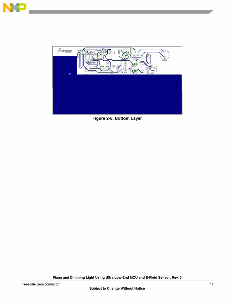
Figure 2-8. Bottom Layer
Piano and Dimming Light Using Ultra Low-End MCU and E-Field Sensor, Rev. 0
Freescale Semiconductor 17Subject to Change Without Notice

Hardware Description
Piano and Dimming Light Using Ultra Low-End MCU and E-Field Sensor, Rev. 0
18 Freescale SemiconductorSubject to Change Without Notice

Chapter 3 Firmware Description
3.1 Introduction
This section describes MC9RS08KA2 PADL firmware.
3.1.1 Firmware Basics
This project was written using the CodeWarrior™ V 5.1 development tool. The application source file for this demo was written in assembly language.
3.1.2 Application Basics
The application demonstrates how to connect the MC9RS08KA2 to the MC34940.
3.2 Project Introduction
This section introduces and describes firmware implementation of the PADL project.
3.2.1 Coding Convention
All source code was written using guidelines to make the final product more readable.
The most important guidelines:• Variables—Begin in uppercase to distinguish between words.• Subroutines—In uppercase only at the beginning and are underscored to distinguish between
words.• Macros—Uppercase; underscores distinguish between words.• Tags—In the first column of every row.
3.2.2 List of Project Files
These files are required for the project:• Project files—PADL.mcp is the CodeWarrior Project file.• Configuration files—MC9RS08KA2.inc contains definitions. Derivative.inc contains watchdog feed
macro.• Application source files—Main.asm contains the demonstration’s main application.
3.2.3 MCU Peripherals
This section briefly describes the RS08 peripherals used in the project and summarizes the necessary microcontroller resources.
The MC9RS08KA2 MCU is used in this demonstration with the SOIC 8-pin package.
Piano and Dimming Light Using Ultra Low-End MCU and E-Field Sensor, Rev. 0
Freescale Semiconductor 19Subject to Change Without Notice
Firmware Description
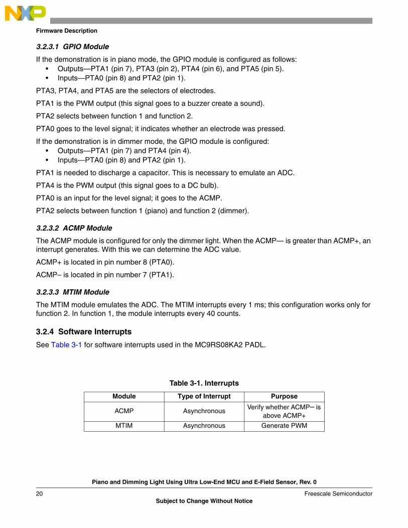
3.2.3.1 GPIO Module
If the demonstration is in piano mode, the GPIO module is configured as follows:• Outputs—PTA1 (pin 7), PTA3 (pin 2), PTA4 (pin 6), and PTA5 (pin 5).• Inputs—PTA0 (pin 8) and PTA2 (pin 1).
PTA3, PTA4, and PTA5 are the selectors of electrodes.
PTA1 is the PWM output (this signal goes to a buzzer create a sound).
PTA2 selects between function 1 and function 2.
PTA0 goes to the level signal; it indicates whether an electrode was pressed.
If the demonstration is in dimmer mode, the GPIO module is configured:• Outputs—PTA1 (pin 7) and PTA4 (pin 4).• Inputs—PTA0 (pin 8) and PTA2 (pin 1).
PTA1 is needed to discharge a capacitor. This is necessary to emulate an ADC.
PTA4 is the PWM output (this signal goes to a DC bulb).
PTA0 is an input for the level signal; it goes to the ACMP.
PTA2 selects between function 1 (piano) and function 2 (dimmer).
3.2.3.2 ACMP Module
The ACMP module is configured for only the dimmer light. When the ACMP— is greater than ACMP+, an interrupt generates. With this we can determine the ADC value.
ACMP+ is located in pin number 8 (PTA0).
ACMP– is located in pin number 7 (PTA1).
3.2.3.3 MTIM Module
The MTIM module emulates the ADC. The MTIM interrupts every 1 ms; this configuration works only for function 2. In function 1, the module interrupts every 40 counts.
3.2.4 Software Interrupts
See Table 3-1 for software interrupts used in the MC9RS08KA2 PADL.
Table 3-1. Interrupts
Module Type of Interrupt Purpose
ACMP Asynchronous Verify whether ACMP– is above ACMP+
MTIM Asynchronous Generate PWM
Piano and Dimming Light Using Ultra Low-End MCU and E-Field Sensor, Rev. 0
20 Freescale SemiconductorSubject to Change Without Notice
Firmware Implementation
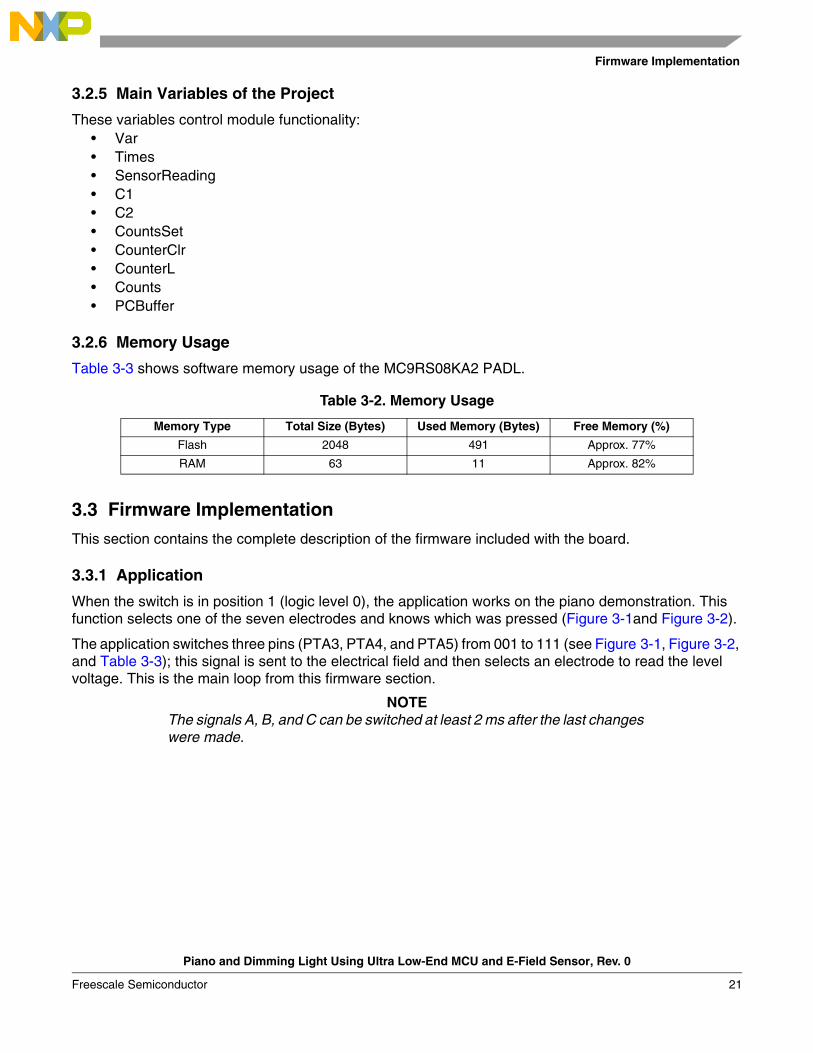
3.2.5 Main Variables of the Project
These variables control module functionality:• Var• Times• SensorReading• C1• C2• CountsSet• CounterClr• CounterL• Counts• PCBuffer
3.2.6 Memory Usage
Table 3-3 shows software memory usage of the MC9RS08KA2 PADL.
3.3 Firmware Implementation
This section contains the complete description of the firmware included with the board.
3.3.1 Application
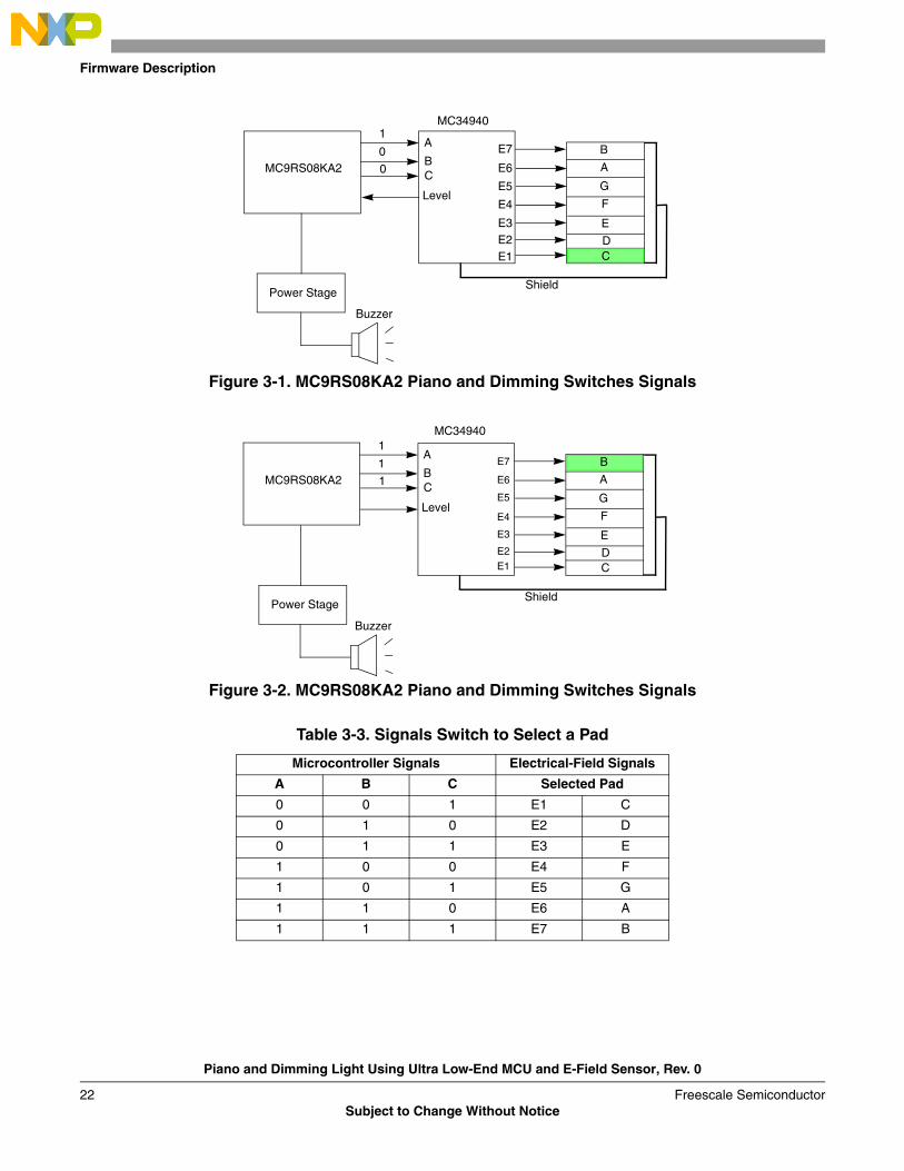
When the switch is in position 1 (logic level 0), the application works on the piano demonstration. This function selects one of the seven electrodes and knows which was pressed (Figure 3-1and Figure 3-2).
The application switches three pins (PTA3, PTA4, and PTA5) from 001 to 111 (see Figure 3-1, Figure 3-2, and Table 3-3); this signal is sent to the electrical field and then selects an electrode to read the level voltage. This is the main loop from this firmware section.
NOTEThe signals A, B, and C can be switched at least 2 ms after the last changes were made.
Table 3-2. Memory Usage
Memory Type Total Size (Bytes) Used Memory (Bytes) Free Memory (%)
Flash 2048 491 Approx. 77%
RAM 63 11 Approx. 82%
Piano and Dimming Light Using Ultra Low-End MCU and E-Field Sensor, Rev. 0
Freescale Semiconductor 21
Firmware Description
Figure 3-1. MC9RS08KA2 Piano and Dimming Switches Signals
Figure 3-2. MC9RS08KA2 Piano and Dimming Switches Signals
Table 3-3. Signals Switch to Select a Pad
Microcontroller Signals Electrical-Field Signals
A B C Selected Pad
0 0 1 E1 C
0 1 0 E2 D
0 1 1 E3 E
1 0 0 E4 F
1 0 1 E5 G
1 1 0 E6 A
1 1 1 E7 B
A
BC
Level
B
A
G
F
E
DC
E7
E6
E5
E4
E3E2E1
Buzzer
Power Stage
MC9RS08KA2
Shield
C
1
0
0
MC34940
A
BC
Level
B
A
G
F
E
DC
E7
E6
E5
E4
E3
E2
E1
Buzzer
MC9RS08KA2
Shield
1
1
1
B
MC34940
Power Stage
Piano and Dimming Light Using Ultra Low-End MCU and E-Field Sensor, Rev. 0
22 Freescale SemiconductorSubject to Change Without Notice

Firmware Implementation
After the electrode is selected, it is assigned the number of counts necessary to generate a musical note. The counts and the MTIM (configured with a prescaler of 1 and 40 counts before interrupts) generate the PWM. The PWM subroutine requires the pulse in the middle of the period (Figure 3-2). If the pulse is not generated at the middle of the period, the resulting frequency is incorrect for the required note.
Figure 3-3. MC9RS08KA2 Piano and Dimming Light PWM
After the sound is generated, the application reads PTA2 and executes the function depending on the switch position.
If the switch changes to position 2 (logical level 1), the application works on the dimmer light. For this part of the firmware only one electrode is selected (signal A is active, signal C is set to GND). When the electrode is pressed, the ACMP detects the voltage change. Then a value is read from the ADC. This value is used to make a PWM and reveal the intensity light in a DC bulb. This application has only five light intensities.
For more information about the firmware, refer to Figure 3-3.
3.3 V
0% 50% 100%
Piano and Dimming Light Using Ultra Low-End MCU and E-Field Sensor, Rev. 0
Freescale Semiconductor 23

Firmware Description
Figure 3-4. MC9RS08KA2 PADL Flowchart Diagram
Start
Is PTA2 pin set?
Scan Electrodes
Is an electrode
Does times variable
Is SensorReading
Configure MCU
Configure MTIM
Configure PTA5, PTA4, and PTA1 as Outputs
Configure PTA4 as Output
Configure MTIM
Discharge Capacitor
Configure Analog Comparator
Read Value from ADC
Increment Times VariableGenerate PWM
Configure MTIM
Generate PWM
Adjust sensor-reading variable for new PWM
= 255?
Which electrode was pressed (Musical note)?
≤ 11?
pressed?
no
no
nono
yes
yes
yes
yes
Piano and Dimming Light Using Ultra Low-End MCU and E-Field Sensor, Rev. 0
24 Freescale SemiconductorSubject to Change Without Notice

Firmware Implementation
Appendix A. BOM and Schematics
Table A-1. MC9RS08KA2 PADL Reference Design Bill of Materials
Item QTY Reference Description Manufacturer Part Number
1 3 C3,C5,C8 0.01μ KEMET 399-1158-1-ND
2 3 C1,C4,C9 0.1 μ KEMET 399-3676-1-ND
3 2 C2,C10 10 μ KEMET 399-3687-1-ND
4 2 C6,C7 47 μ KEMET 7343-31(D-EIA)
5 1 R5 120 Ω Rohm RHM120CC-ND
6 3 R4,R6,R7 1 kΩ Panasonic P1.0KACT-ND
7 2 R10,R11 2.2 kΩ Yageo 311-2.2KARCT-ND
8 1 R8 39 kΩ Yageo 311-39.0KCRCT-ND
9 2 R2,R9 47 kΩ Yageo 311-47KARCT-ND
10 6R1,R3,R12,R13,
R14,R1510 kΩ Yageo 311-10.0KCRCT-ND
11 2 NU Pot 100 kΩ Bourns 3266W-104-ND
12 1 NULm358DR – Op
Amp3-M 296-1014-1-ND
13 1 NUEG4208 –
SwitchE-Switch EG1914-ND
14 1 NUMMBT6427 –
NPN DarlingtonFairchild
SemiconductorMMBT6427-FSCT-ND
15 1 NU MicrocontrollerFreescale
SemiconductorMC9RS08KA2
16 1 NU Electrical FieldFreescale
SemiconductorMC34940
17 1 NUMMBT2222A –
BJTFairchild MMBT2222A-FDICT-ND
18 1 NUB0520WS-7-F –
DiodeTaiwan
SemiconductorB0520WS-FDICT-ND
19 1 NU Buzzer Mallory 458-1064-ND
20 1 NU 7219 – BulbChicago Miniature
CM7219-ND
21 1 NULM2937IMP-3.3 – 3.3V Regulator
National Semiconductor
LM2937IMP-3.3CT-ND
22 1 NUPJ-002A – DC
Power JackCUI Inc CP-002A-ND
Piano and Dimming Light Using Ultra Low-End MCU and E-Field Sensor, Rev. 0
Freescale Semiconductor 25

Firmware Description
Figure A-1. PADL Block Diagram Schematic
Piano and Dimming Light Using Ultra Low-End MCU and E-Field Sensor, Rev. 0
26 Freescale SemiconductorSubject to Change Without Notice
Firmware Implementation
Appendix B. Glossary
• ACMP – Analog comparator module. It provides a circuit to compare two analog inputs’ voltage or one analog input’s voltage to an internal reference.
• ADC – Analog to digital converter. • Binary – Relating to the base 2 number system.• Bit – A binary digit that has a value of logic 0 or logic 1.• Byte – A set of 8 bits.• DC – Direct current.• EEPROM – Electrically erasable and programmable, read-only memory.• Firmware – Instructions and data that control the operation of a microcontroller.• MCU – Microcontroller unit, which is a complete computer system, including a CPU, memory, a
clock oscillator, and Input/Output (I/O) on a single integrated circuit.• PADL – Piano and dimming light.• Port – A set of wires for communicating with off-chip devices.• Prescaler – A circuit that generates an output signal related to the input signal by a fractional scale
such as 1/2, 1/8, 1/10, etc.• PWM – Pulse width modulation.• Toggle – To change the state of an output from logic 0 to logic 1 or from logic 1 to logic 0.• VBatt – Battery voltage.
Piano and Dimming Light Using Ultra Low-End MCU and E-Field Sensor, Rev. 0
Freescale Semiconductor 27
Firmware Description
Piano and Dimming Light Using Ultra Low-End MCU and E-Field Sensor, Rev. 0
28 Freescale SemiconductorSubject to Change Without Notice


How to Reach Us:
Home Page:www.freescale.com
E-mail:[email protected]
USA/Europe or Locations Not Listed:Freescale SemiconductorTechnical Information Center, CH3701300 N. Alma School Road Chandler, Arizona 85224 +1-800-521-6274 or [email protected]
Europe, Middle East, and Africa:Freescale Halbleiter Deutschland GmbHTechnical Information CenterSchatzbogen 781829 Muenchen, Germany+44 1296 380 456 (English)+46 8 52200080 (English)+49 89 92103 559 (German)+33 1 69 35 48 48 (French)[email protected]
Japan:Freescale Semiconductor Japan Ltd. HeadquartersARCO Tower 15F1-8-1, Shimo-Meguro, Meguro-ku,Tokyo 153-0064, Japan0120 191014 or +81 3 5437 [email protected]
Asia/Pacific:Freescale Semiconductor Hong Kong Ltd.Technical Information Center 2 Dai King Street Tai Po Industrial Estate Tai Po, N.T., Hong Kong +800 2666 [email protected]
For Literature Requests Only:Freescale Semiconductor Literature Distribution CenterP.O. Box 5405Denver, Colorado 802171-800-441-2447 or 303-675-2140Fax: [email protected]
Information in this document is provided solely to enable system and software implementers to use Freescale Semiconductor products. There are no express or implied copyright licenses granted hereunder to design or fabricate any integrated circuits or integrated circuits based on the information in this document.
Freescale Semiconductor reserves the right to make changes without further notice to any products herein. Freescale Semiconductor makes no warranty, representation or guarantee regarding the suitability of its products for any particular purpose, nor does Freescale Semiconductor assume any liability arising out of the application or use of any product or circuit, and specifically disclaims any and all liability, including without limitation consequential or incidental damages. “Typical” parameters that may be provided in Freescale Semiconductor data sheets and/or specifications can and do vary in different applications and actual performance may vary over time. All operating parameters, including “Typicals”, must be validated for each customer application by customer’s technical experts. Freescale Semiconductor does not convey any license under its patent rights nor the rights of others. Freescale Semiconductor products are not designed, intended, or authorized for use as components in systems intended for surgical implant into the body, or other applications intended to support or sustain life, or for any other application in which the failure of the Freescale Semiconductor product could create a situation where personal injury or death may occur. Should Buyer purchase or use Freescale Semiconductor products for any such unintended or unauthorized application, Buyer shall indemnify and hold Freescale Semiconductor and its officers, employees, subsidiaries, affiliates, and distributors harmless against all claims, costs, damages, and expenses, and reasonable attorney fees arising out of, directly or indirectly, any claim of personal injury or death associated with such unintended or unauthorized use, even if such claim alleges that Freescale Semiconductor was negligent regarding the design or manufacture of the part.
Freescale™ and the Freescale logo are trademarks of Freescale Semiconductor, Inc. All other product or service names are the property of their respective owners. The ARM POWERED logo is a registered trademark of ARM Limited. ARM7TDMI-S is a trademark of ARM Limited. Java and all other Java-based marks are trademarks or registered trademarks of Sun Microsystems, Inc. in the U.S. and other countries. The Bluetooth trademarks are owned by their proprietor and used by Freescale Semiconductor, Inc. under license.
© Freescale Semiconductor, Inc. 2004. All rights reserved.
DRM085Rev. 010/2006
Related Documents