PHYSICS DESIGN FOR ARIES-CS L. P. KU, a * P. R. GARABEDIAN, b J. LYON, c A. TURNBULL, d A. GROSSMAN, e T. K. MAU, e M. ZARNSTORFF, a and ARIES TEAM a Princeton Plasma Physics Laboratory, Princeton University, Princeton, New Jersey 08543 b Courant Institute of Mathematical Sciences, New York University, New York, New York 10012 c Oak Ridge National Laboratory, Oak Ridge, Tennessee 37831 d General Atomics, San Diego, California 92186 e University of California, San Diego, San Diego, California 92093 Received April 19, 2007 Accepted for Publication August 2, 2007 Novel stellarator configurations have been devel- oped for ARIES-CS. These configurations are optimized to provide good plasma confinement and flux surface integrity at high beta. Modular coils have been designed for them in which the space needed for the breeding blanket and radiation shielding was specifically targeted such that reactors generating GW electrical powers would require only moderate major radii (10 m). These con- figurations are quasi-axially symmetric in the magnetic field topology and have small numbers of field periods (3) and low aspect ratios (6). The baseline design chosen for detailed systems and power plant studies has three field periods, aspect ratio 4.5, and major radius 7.5 m operating at b; 6.5% to yield 1 GW of electric power. The shaping of the plasma accounts for 75% of the rotational transform. The effective helical ripples are very small (0.6% everywhere), and the energy loss of alpha particles is calculated to be 5% when operating in high-density regimes. An interesting feature in this configuration is that instead of minimizing all residues in the magnetic spectrum, we preferentially retained a small amount of the nonaxisymmetric mirror field. The pres- ence of this mirror and its associated helical field alters the ripple distribution, resulting in the reduced ripple- trapped loss of alpha particles despite the long connec- tion length in a tokamak-like field structure. Additionally, we discuss two other potentially attractive classes of con- figurations, both quasi-axisymmetric: one with only two field periods, very low aspect ratios (;2.5), and less complex coils, and the other with the plasma shaping designed to produce low-shear rotational transform so as to ensure the robustness and integrity of flux surfaces when operating at high b. KEYWORDS: power plant studies, quasi-axisymmetric stel- larators, configuration optimization Note: Some figures in this paper are in color only in the electronic version. I. INTRODUCTION ARIES-CS is aimed at investigating the feasibility, cost competitiveness, and physics and engineering issues of using compact stellarators as the core for power- producing fusion reactors. Stellarators are inherently steady-state devices known to be resilient to magnetohydrodynamic ~ MHD! pertur- bations. Data from LHD and W7AS experiments have provided ample support for this proposition. 1,2 Predic- tions of beta limit based on the linear, ideal MHD stabil- ity analysis have been exceeded frequently in experiments, although nonlinear analysis has performed better. The poloidal flux provided by external coils supports the ro- tational transform, making stellarators virtually free of plasma disruptions. In recent years the technique of drift orbit optimization, in which the collisionless particle tra- jectories may be made well confined, has been widely explored. The concept was introduced by Boozer, 3 who showed that expressed in “Boozer” coordinates drift tra- jectories depended only on the local magnetic field strength, 106 B 6 2 , not the vector components of the field. The freedom of being able to use the three-dimensional geometry to shape plasmas in stellarators can be ex- ploited to achieve certain topological symmetry of the magnetic field strength in the plasma. Nuehrenberg et al. *E-mail: [email protected] FUSION SCIENCE AND TECHNOLOGY VOL. 54 OCT. 2008 673

Welcome message from author
This document is posted to help you gain knowledge. Please leave a comment to let me know what you think about it! Share it to your friends and learn new things together.
Transcript

PHYSICS DESIGN FOR ARIES-CSL. P. KU,a* P. R. GARABEDIAN,b J. LYON,c A. TURNBULL,d A. GROSSMAN,e
T. K. MAU,e M. ZARNSTORFF,a and ARIES TEAM
aPrinceton Plasma Physics Laboratory, Princeton University, Princeton, New Jersey 08543bCourant Institute of Mathematical Sciences, New York University, New York, New York 10012cOak Ridge National Laboratory, Oak Ridge, Tennessee 37831dGeneral Atomics, San Diego, California 92186eUniversity of California, San Diego, San Diego, California 92093
Received April 19, 2007Accepted for Publication August 2, 2007
Novel stellarator configurations have been devel-oped for ARIES-CS. These configurations are optimizedto provide good plasma confinement and flux surfaceintegrity at high beta. Modular coils have been designedfor them in which the space needed for the breedingblanket and radiation shielding was specifically targetedsuch that reactors generating GW electrical powers wouldrequire only moderate major radii (�10 m). These con-figurations are quasi-axially symmetric in the magneticfield topology and have small numbers of field periods(�3) and low aspect ratios (�6). The baseline designchosen for detailed systems and power plant studies hasthree field periods, aspect ratio 4.5, and major radius7.5 m operating at b ; 6.5% to yield 1 GW of electricpower. The shaping of the plasma accounts for �75% ofthe rotational transform. The effective helical ripples arevery small (�0.6% everywhere), and the energy loss ofalpha particles is calculated to be �5% when operatingin high-density regimes. An interesting feature in this
configuration is that instead of minimizing all residues inthe magnetic spectrum, we preferentially retained a smallamount of the nonaxisymmetric mirror field. The pres-ence of this mirror and its associated helical field altersthe ripple distribution, resulting in the reduced ripple-trapped loss of alpha particles despite the long connec-tion length in a tokamak-like field structure. Additionally,we discuss two other potentially attractive classes of con-figurations, both quasi-axisymmetric: one with only twofield periods, very low aspect ratios (;2.5), and lesscomplex coils, and the other with the plasma shapingdesigned to produce low-shear rotational transform soas to ensure the robustness and integrity of flux surfaceswhen operating at high b.
KEYWORDS: power plant studies, quasi-axisymmetric stel-larators, configuration optimization
Note: Some figures in this paper are in color only in the electronicversion.
I. INTRODUCTION
ARIES-CS is aimed at investigating the feasibility,cost competitiveness, and physics and engineering issuesof using compact stellarators as the core for power-producing fusion reactors.
Stellarators are inherently steady-state devices knownto be resilient to magnetohydrodynamic ~MHD! pertur-bations. Data from LHD and W7AS experiments haveprovided ample support for this proposition.1,2 Predic-tions of beta limit based on the linear, ideal MHD stabil-ity analysis have been exceeded frequently in experiments,
although nonlinear analysis has performed better. Thepoloidal flux provided by external coils supports the ro-tational transform, making stellarators virtually free ofplasma disruptions. In recent years the technique of driftorbit optimization, in which the collisionless particle tra-jectories may be made well confined, has been widelyexplored. The concept was introduced by Boozer,3 whoshowed that expressed in “Boozer” coordinates drift tra-jectories depended only on the local magnetic fieldstrength, 106B 6 2, not the vector components of the field.The freedom of being able to use the three-dimensionalgeometry to shape plasmas in stellarators can be ex-ploited to achieve certain topological symmetry of themagnetic field strength in the plasma. Nuehrenberg et al.*E-mail: [email protected]
FUSION SCIENCE AND TECHNOLOGY VOL. 54 OCT. 2008 673

were the first to demonstrate that plasmas with quasi-helical symmetry could be constructed in this way.4 Aquasi-helically symmetric stellarator, HSX, has beenbuilt and is operational at the University of Wisconsin,Madison.5 Nuehrenberg, Lotz, and Gori have furthershown that nonaxisymmetric fields can be constructed inwhich 6B 6 is independent of toroidal angles in Boozercoordinates,6 demonstrating the feasibility of construct-ing quasi-axially symmetric ~QAS! configurations.AQASexperiment along these lines has been proposed,7 and themodular Helias-like Heliac ~MHH! configurations weredeveloped for the Stellarator Power Plant Studies8,9
~SPPS!. The NCSX stellarator10 is under construction atthe Princeton Plasma Physics Laboratory and experi-ments are expected to commence in 2009. Another opti-mized stellarator, QPS, which was proposed on the basisof quasi-poloidal symmetry, is being considered at OakRidge National Laboratory.11 W7X, which is under con-struction in Greifswald, Germany, is also an optimizedstellarator, but it uses the concept of quasi-isodynamicityand linked mirrors.12 These optimized stellarators areexpected to have stable plasmas with good confinement,raising the prospect that fusion reactors may be designedwith good particle orbit confinement typically found intokamaks and MHD-stable plasmas typically found instellarators but without the need to have elaborate feed-back controls and large amount of recirculating power.
Stellarator fusion reactors have been studied in thepast, but all of them are large in comparison to the plantsbased on toroidally symmetric power cores. For exam-ple, FFHR ~Ref. 13!, a reactor based on the concept ofLHD, has major radius;14 m; HSR ~Ref. 14!, a reactorbased on W7X, ;18 m; and SPPS ~Ref. 9!, a four fieldperiod, QAS concept, 14 m. Our challenge is to makestellarator power plants competitive in size and cost totokamak-based power plants without compromising thedesirable physics properties and engineering require-ments. To achieve this objective we have concentrated onQAS configurations with small aspect ratios. If the mag-netic field strength can be made truly axially symmetricin magnetic coordinates, then the particle drift orbits willlook exactly the same as those in a tokamak and particleswill be well confined as in a tokamak. On the other hand,as aspect ratio becomes smaller, the toroidal mode cou-pling has less effect on the symmetry properties of theaxially symmetric configurations. These QAS configu-rations can be designed with aspect ratios, average ellip-ticity, and triangularity similar to those of the advancedtokamaks. The plasma is expected to be able to rotatefreely in the direction of quasi-axisymmetry, allowingone to apply the same technique for transport barrierformation as in tokamaks. Due to the quasi-axisymmetry,the neoclassical bootstrap current is similar to that intokamaks, but the magnitude is reduced by the higherrotational transform. The low aspect ratio QAS configu-rations therefore tend to be like hybrids between toka-maks and conventional stellarators.
These positive traits of stellarator power plants haveto be balanced by the complexities they introduce byvirtue of lacking the geometric symmetry. The feasibilityof remotely maintaining the machine in a reactor envi-ronment must be ascertained and the cost associated withthe increased complexity must be controlled. A machineof smaller size may be realized if we can find a config-uration of small aspect ratio that is stable at high beta.However, in deuterium-tritium ~D-T! reactors, becausetritium breeding is required to maintain the fuel self-sufficiency and shielding is required to protect the coilsfrom radiation damage and nuclear heating, consider-ation given solely on the basis of plasma properties is notadequate. One has to be able to find coils that not only arecapable of producing plasmas with the desirable proper-ties but also are sufficiently away from the plasma toprovide enough room for the blanket and shielding. Be-cause the high-order harmonics of magnetic fields decayrapidly, it may not always be feasible to place coils at anarbitrary distance from the plasma. Coil design in stel-larators is an integral part of the configuration develop-ment. The singly most important figure of merit for apower plant is the cost of electricity ~COE!, and to re-duce COE the plant size is one of the most importantparameters in the design optimization. The plant size isdirectly related to the separation between the last closedmagnetic surface and the coils. It is our goal to constructa compact reactor system consisting of an optimized com-pact stellarator core and a compact set of coils in a co-herent and consistent manner.
The development of the ARIES-CS configurationsnaturally evolved from the design of NCSX. We haveidentified the two most critical issues we need to addresswhen extending NCSX to a reactor—the separation dis-tance between coils and plasma and the energy loss ofalpha particles. The efforts to improve designs in thesetwo areas led to the plasma configuration, N3ARE, andcoil configuration, KZD, that were chosen as the baselinefor systems and detailed engineering studies. In addition,we have explored the QAS configuration space to un-cover configurations that may have even more attractiveproperties as reactors. Our exploration led us to the dis-covery of new classes of configurations and enabled us todemonstrate the richness of the landscape.15
This paper is organized as follows: In Sec. II weintroduce the baseline configuration, for both the basicphysics properties and the coil geometry. The physicsand coil configurations are used in the systems and en-gineering studies reported in the companion papers inthis issue. In Sec. III we discuss the methodology andapproaches we used to develop our configurations. Thedetailed discussion of the physics basis for the baselineconfiguration is given in Sec. IV. In Sec. V we presentresults of a broadened study of the configuration spaceusing two classes of configurations as examples. Theseadvanced configurations have not been examined in de-tail in the systems and engineering designs but hold the
Ku et al. ARIES-CS PHYSICS DESIGN
674 FUSION SCIENCE AND TECHNOLOGY VOL. 54 OCT. 2008

promise that compact stellarators of even more attractiveproperties as the core of fusion power plants may befound. In Sec. VI we discuss the research and develop-ment ~R&D! needs to resolve some of the design issuesthat we encountered during the course of the ARIES-CSstudy. A summary and conclusions are given in Sec. VII.
II. THE BASELINE CONFIGURATION
II.A. Characteristics of the Plasma Configuration
The baseline plasma configuration, N3ARE, se-lected for detailed systems code and engineering designanalyses is a three–field period configuration with a plasmaaspect ratio 4.5 and major radius 7.75 m. The aspect ratiois similar to that of NCSX and the configuration may beregarded as an extension or upgrade of NCSX. The majorradius is determined primarily by the fusion power andtritium breeding requirements. The fusion power outputPf is proportional to b2B4R30A2, with the proportionalityconstant being the normalized, volume-averaged fusionreactivity. Here, B is the magnetic field at the magneticaxis, b is the ratio of the average plasma pressure to thevacuum magnetic pressure, R is the plasma major radius,and A is the plasma aspect ratio defined as the ratio of theplasma major radius to the average minor radius aroundthe torus. A steady state is attained when the power out-flow is balanced by the power input from the chargedfusion products, the a particle in the case of D-T fusion.The optimization for COE in the systems code led to thedesign point characterized by B � 5.7 T, ^n& � 4.01 �1020 m�3, ^T &� 6.55 keV, Zeff �1.13, and b� 6.4% fora 1-GW electric power plant, where ^n& is the average iondensity and ^T & is the density weighted average temper-ature. Our plasma has a volume 444 m3 ~or, equivalently,0.95R3! and a surface area 707 m2 ~11.78R2!. The total
fusion power is 2436 MW. The total toroidal plasma cur-rent is estimated to be ;4 MA due to neoclassical boot-strap current. The plasma density is about 1.5 times higherthan the Sudo density,16 but it is consistent with recentexperimental data.17 The density is chosen to minimizethe energy loss of alpha particles, which is about 5%. Theimpurity density is chosen to increase the core radiationby introducing Fe ~0.008%! to reduce the particle heatload on the divertor. The configuration has a magneticwell of ;1% in the absence of the plasma pressure. Thewell deepens to ;15% at 5% b. The effective helicalripple ~«eff ! of the configuration is very low, ;0.6% atthe last closed magnetic surface ~LCMS! and ;0.1% inthe core region. The effective ripple is not sensitive to thechange of the magnitude and profile shape in the plasmapressure. The path to ignition requires a minimum sup-plemental power of ;20 MW. For discussions of thesystems parameters, the reader is referred to the compan-ion article on the systems optimization studies.18
The baseline plasma is a member of the configura-tion family whose magnetic spectrum has a toroidallyquasi-symmetric structure, but the residue mirror andhelical terms are “biased” to retain a small magnitude,typically a few percent of the magnetic field strength onthe axis, to improve the orbit confinement for energeticparticles. As noted earlier, QAS allows us to developconfigurations with smaller aspect ratios. We find that byintroducing the selected non–axially symmetric ~n � 0!components in the low–aspect ratio QAS, the secondaryripple wells, if present, may be modified in such a waythat ripple-trapped loss of energetic particles is mini-mized ~Sec. III.B!.
The geometry of the LCMS is illustrated in Fig. 1.In Fig. 2 we show four cross sections of the plasma attoroidal angles 0, p09, 2p09, and p03. The presence ofthe triangular, square, and pentagon components in theshape is evident, giving the configuration a distinctive
Fig. 1. Top and perspective views of the LCMS for the baseline plasma.
Ku et al. ARIES-CS PHYSICS DESIGN
FUSION SCIENCE AND TECHNOLOGY VOL. 54 OCT. 2008 675
bullet-shaped section at the toroidal angle p03. We findthat these components are helpful in making the plasmaless susceptible to MHD instabilities and at the sametime enable the plasma to maintain good quasi axisym-metry. The shape has the general characteristics of NCSX.Figure 3 shows the contours of magnetic field strength asfunctions of normalized toroidal and poloidal angles on a
flux surface halfway in the radial coordinates of the nor-malized toroidal flux. These contours show the underly-ing quasi axisymmetry of the configuration since the linesare in the toroidal direction in most poloidal angles, butone may also observe deviations from this quasi symme-try, particularly on the inboard high-field side of the torus,resulting from having the biased residues in the magneticspectrum.
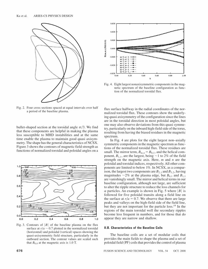
In Fig. 4 are plots for the eight largest non–axiallysymmetric components in the magnetic spectrum as func-tions of the normalized toroidal flux. These residues aresmall. The mirror term, Bm,n � B0,1, and the helical com-ponent, B1,1, are the largest, being ;1 to 2% of the fieldstrength on the magnetic axis. Here, m and n are thepoloidal and toroidal indices, respectively. All other com-ponents are limited to below 1%. In NCSX, as a compar-ison, the largest two components are B2,1 and B3,2, havingmagnitudes ;2% at the plasma edge, but B0,1 and B1,1are vanishingly small. The mirror and helical terms in ourbaseline configuration, although not large, are sufficientto alter the ripple structure to reduce the loss channels fora particles. An example is shown in Fig. 5 where 6B 6 isfollowed for five poloidal transits along a field line onthe surface at r0a � 0.7. We observe that there are largepeaks and valleys on the high-field side of the field line,but they are not important for the particle loss.19 In theregions of the main toroidal well the secondary ripplesbecome less frequent in numbers, and for those that doappear they are narrow and shallow.
II.B. Characteristics of the Baseline Coils
The baseline coils are a set of modular coils thatprovides the main fields to shape the plasma and a set ofpoloidal field ~PF! coils that provides the control of plasma
Fig. 2. Four cross sections spaced at equal intervals over halfa period of the baseline plasma.
Fig. 3. Contours of 6B 6 of the baseline plasma on the fluxsurface at r0a; 0.7 plotted in the normalized toroidal~horizontal! and poloidal ~vertical! spaces showing thequasi-axisymmetric field structure, particularly in theoutboard section. The contour values are scaled suchthat B0,0 at the magnetic axis is 1.0 T.
Fig. 4. Eight largest nonaxisymmetric components in the mag-netic spectrum of the baseline configuration as func-tion of the normalized toroidal flux.
Ku et al. ARIES-CS PHYSICS DESIGN
676 FUSION SCIENCE AND TECHNOLOGY VOL. 54 OCT. 2008

equilibrium in response to pressure changes. The modu-lar coils are shown in Fig. 6. The coils follow the stel-larator symmetry, with three different coil shapes for atotal of 18 coils over the three field periods. The coils aredesigned to be sufficiently far from the LCMS to reduceripples in the plasma due to the discrete coils and to allowrooms for blanket and shielding. One of the most impor-tant figures of merit for optimizing a stellarator powerplant is the so-called coil aspect ratio Ac � R0Dmin~C-P!,the ratio of the plasma major radius R to the minimumseparation between the center of the coil winding and theLCMS Dmin~C-P!. Too large a coil aspect ratio may leadto a large power plant because of the required minimum
shield0blanket thickness. Too small a ratio may lead to acomplicated coil because of the rapid decay of the neededhigh-order harmonics of the magnetic field. The baselinecoils were designed to have a coil aspect ratio 5.9 andalso a coil-to-coil separation ratio R0Dmin~C-C! � 10,whereDmin~C-C! is the minimum separation among coils.Thus, for the baseline configuration there is a minimumseparation of 0.77 m between adjacent coils and a min-imum distance of 1.31 m from the LCMS. A plot showingthe coil-to-plasma distance in the entire toroidal-poloidaldomain is given in Fig. 7. The distance in the neighbor-hood of the minimum separation increases sufficientlyfast that a tapered ~nonuniform! blanket and shield sys-tem may be used to minimize the major radius of thereactor.20
The maximum magnetic field in the coil is aboutthree times the field at the magnetic axis if the conduc-tors have a square cross section with side width 0.3 m~not the reference design!. This peak field ratio is re-duced to ;2 for square conductors of width 0.6 m. Theuse of ribbon-like cross section for coils seen in Fig. 6 isour further effort to maximally utilize the space betweenthe plasma and coils for radiation shielding and tritiumbreeding. The conductors have a height 0.194 m radiallyand a width 0.743 m toroidally. The maximum field inthe winding pack of the coils is ;15 T for an on-axisplasma field of 5.7 T. The high magnetic field in themagnets requires the use of Nb3Sn as the superconductormaterial. It is possible to reduce the maximum field byincreasing the size of the reactor to yield the same fusionpower since it scales like B4R3. We allow currents in thecoils to be different, 10.8, 13.5, and 13.1 MA, respec-tively, leading to a maximum winding current density;94 MA0m2 and a maximum normalized currentIc0R{B � 0.306 MA0m{T. The lengths of the coils nor-malized to the major radius are 4.77, 5.08, and 5.14,
Fig. 5. 6B 6 along a field line on the flux surface at r0a ; 0.7of the baseline configuration for five poloidal transitsstarting from f � 0, u � 0 in the Boozer magneticcoordinates. The field strength is scaled such thatB0,0 � 1.0 T
Fig. 6. Top and side views of the baseline modular coils.
Ku et al. ARIES-CS PHYSICS DESIGN
FUSION SCIENCE AND TECHNOLOGY VOL. 54 OCT. 2008 677
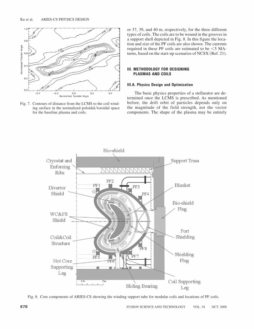
or 37, 39, and 40 m, respectively, for the three differenttypes of coils. The coils are to be wound in the grooves ina support shell depicted in Fig. 8. In this figure the loca-tion and size of the PF coils are also shown. The currentsrequired in these PF coils are estimated to be ,5 MA-turns, based on the start-up scenarios of NCSX ~Ref. 21!.
III. METHODOLOGY FOR DESIGNING
PLASMAS AND COILS
III.A. Physics Design and Optimization
The basic physics properties of a stellarator are de-termined once the LCMS is prescribed. As mentionedbefore, the drift orbit of particles depends only onthe magnitude of the field strength, not the vectorcomponents. The shape of the plasma may be entirely
Fig. 7. Contours of distance from the LCMS to the coil wind-ing surface in the normalized poloidal0toroidal spacefor the baseline plasma and coils.
Fig. 8. Core components of ARIES-CS showing the winding support tube for modular coils and locations of PF coils.
Ku et al. ARIES-CS PHYSICS DESIGN
678 FUSION SCIENCE AND TECHNOLOGY VOL. 54 OCT. 2008

nonsymmetric but the underlying field strength still canbe made to follow certain symmetry. The residues in themagnetic spectrum due to the plasma shaping to giveperfect symmetry cannot be entirely eliminated in theentire volume of the plasma; only approximate quasi sym-metry can be achieved in practical designs. The physicsoptimization then is such that the plasma boundary isallowed to deform to maximize the symmetry property inthe plasma while constraints are imposed to improve otherphysics properties. Mathematically, this is a nonlinear,constrained optimization problem.
It is convenient to represent the boundary of plasmain the following compact form:
R � iZ � e iu(Dm, n e�imu�inv , ~1!
where R and Z are the radial and axial components of acylindrical coordinate, m and n are the poloidal and to-roidal mode numbers, and u and v are the normalizedpoloidal and toroidal angle-like variables.22 The coeffi-cient D1.0 is the plasma major radius and D0,0 is a measureof the plasma minor radius. Without losing generality, welet D0,0 be 1 so that D1.0;A. For the m �1, 2, and 3 termsin Eq. ~1!, we obtain helical excursion, elongation, andtriangularity, respectively, in the shape of the plasma. Form � �1 we obtain the crescent that contributes to themagnetic well and helps with stability. Most of the rota-tional transform in our cases comes from D2,1. The mag-netic field strength on an equilibrium surface s is typicallyrepresented as a double Fourier series in Boozer mag-netic coordinates,
B~s! �( Bm, n~s!cos~mu� @n � im#f! . ~2!
The coefficients Bm,n in Eq. ~2! for the poloidal modenumber m and toroidal mode number n are typically re-ferred to as the magnetic spectrum. In Eq. ~2!, i is therotational transform on a surface labeled by the normal-ized toroidal flux s and @n � im# denotes this being thestraight field line coordinate. For quasi axisymmetry, oneminimizes contributions of Bm,n for which n � 0. Al-though D2,1 delivers most of the rotational transform inour cases, the corresponding term B2,1 in the spectrum isusually small.
For the baseline plasma, the LCMS is characterizedby D2,1 � �0.41, D2,0 � �0.25, D�1,�1 � 0.17, D3,1 �0.15, D3,0 � 0.14, D�1,0 � 0.11, D0,1 � 0.07, D3,2 � 0.06,and D4,0 � �0.06, giving an average elongation ;1.7and triangularity ;1.
We began the development of our configurations byrestricting m � 6 and n � 4 in the initial prescription forthe plasma boundary. An initial set of Dm,n was chosenand solutions were sought such that residues in the mag-netic spectrum, with the exception of a few selected com-ponents, were minimized and the following conditionswere met. We require that the residues in the magnetic
spectrum be low enough so that the effective helical rip-ples on all surfaces will be ,1% and the collisionlessloss orbits of alpha particles are minimized during a smallnumber of toroidal transits, typical ;500. The completecalculation, including the slowing-down processes, for aloss is carried out during the analysis phase since such acalculation is too expensive to be practical in optimiza-tion. We asked, moreover, that the rotational transformsupplied by rippling the boundary alone be of certainshape and magnitude ~for the baseline, monotonicallyincreasing and of magnitude 0.45!, that the transformincrease as radius increases, and that there exist a mag-netic well in the absence of the plasma pressure. Al-though recent results from W7AS and LHD showed thatthe linear, ideal MHD theories have limited applicabilityin predicting the stability limit in stellarators, we stillincluded the stability to the infinite-n ballooning andideal external kink modes calculated based on such theo-ries as constraints in the optimization since in the NCSXstudies we found that including, for instance, the externalkinks as a constraint, the structure of local shears wouldrespond in such a way that the resulting configurationwould generally have more favorable MHD stabilitycharacteristics.23 However, we did not strictly enforcesuch constraints, and in some advanced configurationsthese constraints were relaxed considerably, as suggestedby the nonlinear theory.24 Additionally, we monitorthe boundary harmonics to minimize the impact of res-onant perturbations due to the existence of low-orderrational surfaces. These perturbations manifest in the for-mation of magnetic islands, which, if large enough, wouldenhance the radial loss due to plasma flow along fieldlines.
The search and optimization were carried out by anefficient nonlinear optimization package, STELLOPT,developed during the design of NCSX ~Ref. 25!. In thispackage either a modified Levenberg-Marquadt algo-rithm or the genetic or differential evolution techniquesmay be used for the search. VMEC ~Ref. 26! is used forthe equilibrium evaluation. Function evaluations weremade in parallel, in either the gradient calculations whenthe local gradient search algorithm is used or the “fit-ness” calculations when the genetic or differential evo-lution algorithm is used. We find that it is also useful tostudy plasma equilibrium by the NSTAB code22,27 andthe PIES code.28 The PIES code is useful when used toexamine the quality of equilibrium since it does notpresume the existence of nested flux surfaces. The opti-mization program uses separate modules to evaluateelements of the penalty function. These modules includeevaluation of parameters concerning the basic plasmaproperties ~such as the desired amount of external rota-tional transform, the magnetic shear, and magnetic welldepth!, the MHD instability growth rate ~such as exter-nal kinks and infinite-n ballooning!, and transport fig-ures of merit ~such as «eff , diffusion coefficients, andcollisionless loss of a particles!. Typically, we evaluate
Ku et al. ARIES-CS PHYSICS DESIGN
FUSION SCIENCE AND TECHNOLOGY VOL. 54 OCT. 2008 679

the effective helical ripple by NEO ~Ref. 29!, the a-particle transport by the guiding center code ORBIT3D~Ref. 30!, the kink stability by Terpsichore,31 the bal-looning stability by CORBA ~Ref. 32!, and the thermaltransport by TRANS ~Ref. 33!.
The importance of a loss resulting from the breakingof axisymmetry in D-T stellarator reactors has been re-alized for quite some time. Gori et al. have used a MonteCarlo algorithm to minimize the loss of trapped alphas.34
Subbotin et al. have tried the method of maximizing thepsuedosymmetry and the technique of closing the con-tours of the second adiabatic invariant.35 We have exam-ined various methods and find that a combination ofminimizing the residues of the nonaxisymmetric compo-nents in the magnetic spectrum and maximizing the av-erage resident times of the collisionless a’s of all classesprovides a robust and efficient means to identify config-urations with the reduceda loss. In applying the ORBIT3DMonte Carlo code to the physics optimization that in-volves only the collisionless process, the parameters thatwould be affected by the “randomness” are only the ini-tial positions and pitch angles of the particles. By usingthe same seed to start the pseudorandom number gener-ator in the Monte Carlo process, the random walks wouldbe highly correlated in the gradient calculations, and theresulting stochastic effect is minimized in the determi-nation of the direction of the steepest descent in the equi-librium parameter space. We find that the Monte Carloapproach is effective and robust even when restricted toa small sample size, a small cutoff lost fraction, and alimited number of toroidal transits.
It is important to point out that unlike other ARIESstudies for tokamaks, in which ample theoretical andexperimental understanding have been used to extrapo-late to the design of reactors, there are very few data fordrift orbit–optimized stellarator devices. The understand-ing of plasmas in three-dimensional configurations isfrom non–drift optimized devices. Experimental datafrom existing devices indicate that stellarators are moreresilient to MHD perturbations than the linear, idealtheory tells us. The widely used ISS95 scaling36 for theenergy confinement times was derived from a set ofsmall stellarators, most of them not drift optimized.Results of recent experiments have already exceededthe prediction by this scaling law, and a scalar “H”factor is typically applied to match the increased con-finement observed in experiments. The Sudo densitylimit,16 which was derived from an earlier heliotron andwhich has been considered to be more appropriate forstellarators, has been exceeded ~e.g., in LHD, Ref. 17!.Perhaps the nonlinear theory will help to address theseissues.33,45 At present, there are uncertainties in settingup the physics targets in the design of optimal configu-rations. The approach taken here is generally conserva-tive ~imposing more constraints! and may be relaxedwhen further understanding is available, e.g., from NCSXexperiments.
III.B. Coil Design and Optimization
Coils that produce the designed target plasma shapemay be constructed by requiring that the surface normalcomponent of the magnetic field they produce on theLCMS cancel that due to the plasma current. Variousnumerical techniques have been devised for this “reverseengineering” of the coils.37,38 We have established a three-staged approach. First, the current potential on a pre-scribed coil winding surface is determined by minimizingthe residues of the magnetic field normal to the LCMS.From the current potential we obtain an approximate coildesign. Second, we allow the winding surface geometryas well as the geometry of the coils wound on this surfaceto vary so as not only to minimize the field errors on theLCMS but also to enforce additional constraints, such asthe minimum separation to the plasma or to the neigh-boring coils, coil curvature, and other engineering prop-erties. We typically require that the maximum local residue~6dBn60B! be ,2% and the overall average residue be,0.5%. Last, we directly solve for the free boundaryequilibrium and optimize both the physics and engineer-ing properties simultaneously instead of minimizing thenormal field errors on the boundary defined by the orig-inal fixed boundary plasma, again by allowing both thewinding surface topology and the coil geometry to vary,using coil parameters obtained from step 2 as the initialcondition. The last step is a complicated and difficultprocedure and has been used here only for the very lowaspect ratio MHH2 case ~see Sec. V.A!.
We represent the coil shapes parametrically as two-dimensional Fourier series in terms of toroidal and po-loidal angles on a winding surface. The winding surfaceitself in turn is represented as Fourier series in the to-roidal and poloidal angles. This double representationhas an advantage in that it allows one to choose theinitial coil geometry in a more flexible and intuitiveway. The initial choice of the winding surface is impor-tant since the optimization is highly nonlinear and theconfiguration space is complex with many valleys andhills. The optimization finds a “local” minimum of thepenalty function we specified. We cannot ascertain theexistence of a unique solution in this multidimensionaloptimization.
In D-T reactors, the requirements of tritium breed-ing and coil protection from radiation damage typicallyset the minimum thickness for the blanket and shield-ing. As mentioned before, if the coil aspect ratio Ac
becomes too small, allowing more room for the firstwall, blanket, and shielding for a given R, the shape ofthe coils may become too complex to be attractive. Ifthe ratio becomes too large, the size of the machinemay have to be increased to provide enough space, andtherefore the machine may become too big and the powerdensity too low, irrespective of the compactness of theplasma itself. In addition, the maximum magnetic fieldin the plasma, and therefore the power density, is limited
Ku et al. ARIES-CS PHYSICS DESIGN
680 FUSION SCIENCE AND TECHNOLOGY VOL. 54 OCT. 2008

by the maximum allowable field in the coil body. Fig-ure 9 shows an example study of the peak magneticfield in the coils as the coil aspect ratio is varied in oneof our earlier studies for the baseline configuration. It isseen that there is a critical coil aspect ratio about 6.Below this, the increased coil current and coil complex-ity lead to higher fields in the coil body. Above this, theincrease in current density due to the limited space forthe coil also leads to higher fields. We therefore in-cluded the coil aspect ratio as a constraint in the designoptimization.
Additionally, coils must also have adequate separa-tions among themselves and have sufficiently large bendradii throughout the winding. These considerations willhelp coil manufacturing, port installation, machine as-sembly, and remote maintenance. Thus, we also imposethe constraints of coil separation ratio and the minimumradius of curvature in the coil optimization. We allowcoils to have different currents, but they have to maintainthe stellarator symmetry @i.e., R~u,f! � R~�u,�f!,Z~u,f! � �Z~�u,�f!# . Typically, we search for solu-tions with coil aspect ratio ,6, coil separation ratio,12, and the ratio of the major radius to the minimumradius of curvature ,12. During the third stage of opti-mization in which free boundary equilibrium is solved,we vary coil geometry as well as coil currents to mini-mize the nonaxisymmetric “noise,” the effective ripple,the collisionless loss of a particles, etc., as discussed inSec. III.A.
IV. PHYSICS BASIS FOR THE BASELINE
CONFIGURATION
IV.A. Plasma Equilibrium and MHD Stability
Equilibria of the baseline configuration have beenstudied using both the VMEC and PIES codes for b rang-ing from 4 to 8%. In VMEC, it is assumed that fluxsurfaces are closed and nested. Most of our stability andtransport calculations take advantage of this assumptionto map VMEC solutions to the Boozer magnetic coordi-nates for analysis. In Fig. 10 are flux contours at theoblate cross section calculated using VMEC for an equi-librium at 5% b. The profiles of plasma pressure andcurrent used in the calculation are illustrated in Fig. 11.The normalized plasma current ~Ip0R{B! due entirely tobootstrap at b � 5% is ;0.08 MA0m{T and is propor-tional to ;b0i, where i is the total rotational transform.The bootstrap current is determined by the Fourier spec-trum of 6B 6 in Boozer coordinates. In QAS, the n � 0coefficients are small and the bootstrap current is similarto that in a tokamak. In particular the bootstrap current isin a direction that reinforces the externally generatedrotation transform. Here, we adopted as a starting pointthe pressure and current profiles from ARIES-RS~Ref. 39!, in which the current profile was well alignedwith the bootstrap current. Because the bootstrap currentis determined by the n � 0 components of 6B 6, we retainrough consistency with the bootstrap drive. Adjustmentswere made in the profile using a three-dimensional boot-strap code40 in which a connection formula valid in theentire range of collisionality was used in the calculationof the bootstrap current. The rotational transform profileas a function of the normalized toroidal flux for b; 5%is given in Fig. 12, in which both the external transform
Fig. 9. Example showing that the maximum magnetic fieldintensity in the coil body has a minimum with respectto the coil aspect ratio if the space needed for blanket0shielding is imposed as a constraint. The data shownhere are based on a design of modular coils with topol-ogy similar to that given in Fig. 6 but with R; 8.3 mand B0 ; 5 T. We have assumed that a thickness of1.1 m is required for blanket0shield, plasma scrape-off,thermal insulation, coil case, etc. and that the remain-ing space available is used for the radial dimension ofthe coil conductor. The top curve is for conductors withsquare cross sections; the bottom curve is for conduc-tors with a fixed width of 0.4 m.
Fig. 10. Flux surfaces of the baseline configuration at 5% bfrom a VMEC solution.
Ku et al. ARIES-CS PHYSICS DESIGN
FUSION SCIENCE AND TECHNOLOGY VOL. 54 OCT. 2008 681

and the total transform including the internal contribu-tion from the plasma current are shown. The externaltransform ranges from;0.4 to;0.5, and the total trans-form rises to ;0.7 near the edge. The core transform islarge enough such that the Shafranov shift ~;bA0i2! ismodest, ;10% of the minor radius at 5% b.
Figure 13 shows the result of an equilibrium calcu-lation using the PIES code, which does not presupposethe existence of nested flux surfaces. Field lines are fol-lowed to trace out the separatrix near rational surfaces. Itis seen that although the total rotational transform passesthrough the 305 and 306 resonances, the surfaces main-tain an overall good integrity throughout the entire plasma,with only a relatively small loss of the fluxes. Indeed, theresonance perturbation to the 305 mode is very small sothat this island chain is not clearly resolved in the calcu-lation. The shear in our configuration is designed to havepositive sign relative to the direction of the plasma cur-rent; therefore the perturbed bootstrap currents suppressmagnetic island when a resonance exists. This effect isnot included in the PIES calculation. In NCSX, an esti-mate of this effect was made and it was found that when50% of the rotational transform is from the bootstrapcurrent, an island whose width would otherwise be 10%of the minor radius is suppressed to about 0.5% of theminor radius.41
We have used computer codes based on the linear,ideal MHD assumption to monitor the stability proper-ties of our configuration and to help guide the designoptimization. However, we should point out that al-though the upper linear MHD stability boundaries for bwere found to be �2% in LHD and W7AS, experimentsachieved beta greater than 3 to 4% for durations muchlonger than the energy confinement time ~for example,see Ref. 42!. A nonlinear analysis for one of our earlierQAS configurations also indicated a higher stabilityboundary than that calculated by the linear, ideal MHD~Ref. 24!. Nevertheless, codes based on the linear, idealtheory are readily available, are easier to use, and do notdemand too much computational resources. We use themto delineate the linear stability boundary and as a basisfor discussing MHD stability characteristics, but we do
Fig. 11. Pressure ~solid line! and current density ~dotted line!profiles used for the equilibrium and MHD stabilitycalculations.
Fig. 12. Rotational transform profiles for the baseline config-uration versus the normalized toroidal flux s. The dot-ted line is the transform due to the deformation of theplasma surface. The solid line is the total transformincluding the contribution from the plasma current.
Fig. 13. Poincaré plot for the PIES solution of an equilibriumof the baseline plasma at 5% b.
Ku et al. ARIES-CS PHYSICS DESIGN
682 FUSION SCIENCE AND TECHNOLOGY VOL. 54 OCT. 2008

not restrict beta in the search for the operating point inthe systems optimization since the credible MHD betalimit is not known at present. Beta limits in stellaratorsare an important research subject that needs to be sys-tematically studied in the years to come. We have tar-geted 4% linear stability beta in the configurationoptimization, similar to that used in developing the con-figuration for NCSX. The beta chosen for the baselineoperating point is ;6.5%, or about 60% above the tar-geted linear stability boundary.
Our analysis showed that the configuration is stableto the vertical mode, as expected from the theoreticalanalysis.43 The control coils normally required in toka-maks are not needed. The Terpsichore code31 is used tostudy the kink stability. The calculation based on theresolution used in the optimization process ~49 radialgrids, 59 equilibrium modes, 264 Boozer modes, and 91perturbation modes! indicates that the kink stability bound-ary of the configuration is about 4%. At 5% b, the con-figuration is weakly unstable without a conducting wall.A systematic sensitivity study for the configuration using197 surfaces and up to 101 toroidal-poloidal angle com-binations yields a slightly more pessimistic but more com-plete picture. Preliminary results with the higher resolutionindicate that the reference case with b� 4.06% is actu-ally slightly unstable. The “symmetry preserving” ~i.e.,n � 3 family! mode is a predominantly m0n � 906 modestrongly peaked at the edge with 503 and 1006 sidebandsand is near marginal ~eigenvalue equal to the square ofthe growth rate in Alfvén time units of g2;10�6!. How-ever, the symmetry-breaking mode is a much more globalm0n � 302 mode with 604, 201, 204, and 805 sidebands.The growth rate, with g2 ; 10�4, is moderately small,indicating a proximity to the b limit. The b limit foundfrom varying the pressure uniformly at fixed i then ap-pears to be a little below b � 4%. Further convergencestudies would be needed to fully confirm this, but theLHD and W7-AS experimental results seem to indicatethat this level of instability at b� 4% is robustly toler-ated in practice. At higher b several modes become un-stable, and for b� 8.2% there are two external and oneinternal symmetry-breaking modes unstable with one un-stable symmetry-preserving mode. For the most unstablesymmetry-breaking mode, the 201 component is domi-nant. The external “symmetry-preserving” and symmetry-breaking modes are stabilized by a conformal wall at 1.2times the average plasma minor radius. However, theinternal symmetry-breaking 201 mode remains unstableeven with the wall on the plasma boundary, albeit with avery low growth rate, g2;10�7. This is not expected tobe significant.
The reference equilibrium has an i � 203 surfaceright at the edge of the plasma and the sensitivity to thepresence of this i � 203 surface was also investigated.With the 203 surface removed at constant b, the equilib-rium is marginally unstable to an m0n�1305 mode peakedin the core. On increasing i so that the i � 203 surface
moves deeper into the plasma, the 302 mode is destabi-lized. This mode requires a conformal wall within 1.1times the average plasma minor radius for stability.
The study for the Mercier mode showed that theconfiguration is stable at 6% b and for the infinite-nballooning modes stable at ;4% b. At 5% b, however,the ballooning unstable zone occupies only;10% of theradial width peaked at r0a; 0.9. In NCSX, it was foundthat using the finite but high-n calculation ~n ; 20! toaccount for the finite Larmor radius effect results in amuch higher ballooning beta limit, typically by ;50%~Ref. 44!. Because of the similarity of the field structurebetween NCSX and the baseline plasma, we believe thatour configuration is actually stable against the balloon-ing modes to ;6% b. We have observed the beneficiaryeffect of the mirror term B0,1 on the ballooning stabilityin our previous study of a three–field period QAS~Ref. 24!. We are able to take advantage of the mirrorfield in the baseline configuration to improve both thestability and confinement of the fast particles.
The rotational transform has a positive shear in mostof the plasma region; thus the configuration is expectedto be stable to the neoclassical tearing modes as well. The609 resonance and the shear reversal near the boundaryare of concern. We shall investigate the need to modifythe transform profile in the future.
Plasma equilibria depend on the details of the plasmapressure and current profiles. Sensitivity calculations havebeen carried out to study their effects on the quasi-axisymmetry and MHD stabilities. The pressure profilewas represented as ~1 � s a!b in this study with a variedfrom 1 to 10 and b from 1 to 2.5. Here s is the normalizedtoroidal flux. The corresponding current profiles werederived, with additional variations in the density profile,from calculations of a three-dimensional bootstrap code.39
We find that quasi axisymmetry is largely unaffected bychanges in the pressure or current profiles since most ofthe rotational transform is generated externally by theshaping of the plasma. The MHD stability responds morefavorably when the peak of the current density shiftsoutward ~resulting in a larger global magnetic shear!.Figure 14 shows a current profile used in one of oursensitivity studies. It is quite different from the one usedin the baseline plasma and is less favorable with respectto the stability as understood from the linear, ideal MHD.Figure 15 shows the amount of boundary deformationrelative to that of the baseline configuration needed tocompletely stabilize the external kink instability at 5% bin the limit of the linear, ideal MHD theory. The fact thatthe needed modification is so small for the very differentcurrent profile indicates that the configuration indeed hasa favorable MHD stability characteristic. Based on oursensitivity studies and in light of the results from recentexperiments, we believe that the choice of ;6.5% bfor the operating point is reasonable from the standpointof MHD stability. If the plasma in this configurationturns out to be more stable than the linear calculation
Ku et al. ARIES-CS PHYSICS DESIGN
FUSION SCIENCE AND TECHNOLOGY VOL. 54 OCT. 2008 683

indicated, either from nonlinear analyses or from exper-iments, then some relaxation of the shaping constraintmay become possible, which may lead to less complexcoils. If, on the other hand, the selected operating b turnsout to be too high, it is possible, for example, to increasethe major radius to ;8.25 m to bring b down to ;4%with only ;7% penalty to the COE ~Ref. 18!.
IV.B. Particle Transport and Confinement
As discussed earlier, the magnetic field structure,although mostly QAS, has certain distinctive features inthe spectrum. In a QAS configuration, the connectionlength is long between good and bad curvature regions sothat particle transport is sensitive to the distribution ofsecondary ripple wells along the field lines. The smallbut nonnegligible mirror term B0,1, together with the side-band helical term B1,1, reduces the effects of the second-ary wells along the path of the toroidally trapped particles,thereby reducing transport losses, as confirmed by a de-tailed analysis of the B � ¹B drifts.19 The secondarywells are either shallow or closer to either the inboard orthe outboard side of the field line where particles withturning points inside the ripple wells average over smallergradient drifts. We note that because we can achieve onlyquasi symmetry, the secondary ripple wells will be present.
However, it is possible to preferentially select or bias thecomponents in the magnetic spectrum to reduce the harmcaused by them. In our baseline configuration the effec-tive helical ripple is very small. Shown in Fig. 16 is thedependence of the effective ripple on the plasma radiusfor b ; 5%. We observe that the effective ripple «eff isless than 0.1% in the core of the plasma and the maxi-mum value is ,0.6%. The diffusion coefficient for the
Fig. 14. Comparison of a broad current profile ~dotted line!used in the kink stability studies with the baselineprofile ~solid line!.
Fig. 15. Comparison of LCMS showing the additional bound-ary deformation needed to make the baseline config-uration ~solid line! kink stable in the ideal, linear MHDlimit at 5% b ~dotted line! when the broad currentprofile in Fig. 14 is used.
Fig. 16. Effective helical ripple as function of normalized to-roidal flux for the baseline plasma.
Ku et al. ARIES-CS PHYSICS DESIGN
684 FUSION SCIENCE AND TECHNOLOGY VOL. 54 OCT. 2008

collisionless transport is proportional to «eff1.5 so that we
expect the loss due to the neoclassical transport will besmall when compared to the anomalous. The effectiveripple does not change much as b varies. The energyconfinement time required for power balance at steadystate is ;1 s. Using the stellarator ISS95 scaling,36
t~s! � 0.256am2.21 Rm
0.65 PMW�0.59 n20
0.51 BT0.83 i0.4 , ~3!
one finds that this requirement will be met if we allow an“H” factor of;2 in the scaling. This enhancement factorhas been achieved in experiments. Monte Carlo simula-tions have been employed to verify some of our conclu-sions.45 We further note that the recently updated ISS04scaling46 will give a more favorable confinement. Theanalysis of the 2004 international stellarator databasesuggests that lower values of effective helical ripple maycorrelate to the higher values of confinement improve-ment. Our configuration is designed to have very loweffective ripples, being ;0.05% at r0a � 203.
In addition to the thermal transport, the loss of alphaparticles is an important issue not only because it affectsthe power balance but also because it drives the divertorand protective plate design. The configuration is de-signed to minimize the collisionless loss by optimizingthe secondary ripple well distribution. It is also opti-mized to reduce the collisional loss by increasing thecollisionality of the alpha particles with the backgroundthermal species. Generally, we find that the alpha energyloss scales like R2B2 for a fixed plasma aspect ratio. Theloss also scales strongly with respect to the collisionality.Figure 17 shows parametrically the effects of the colli-sionality on the loss of alpha in two reactor sizes. Thehigh collisionality reduces the alpha-particle slowing-down time. This also decreases the total energy in the
alpha-article distribution function, decreasing the drivefor fast ion and Alfvénic instabilities. In this parametricstudy both the temperature and density profiles of thebackground ions and electrons were assumed to be par-abolic and the a emission profile of the form ~1 � r0a! 8.In the baseline configuration, we have chosen a highdensity and high magnetic field intensity for the plasmato minimize the loss, but they are consistent with both thedensity limit experimentally observed and the criticalfield in the superconductor at the designed current den-sity. Our analysis shows that the loss fraction of the en-ergy of alpha particles is ;5%, or ;20 MW. This resultis based on the ORBIT3D Monte Carlo calculations inwhich 4096 alphas were followed for;200 ms, or abouttwice the slowing-down time, with an estimated statisti-cal error of ;15%. In addition to the parabolic profilesused in the parametric study, in the final analysis we havealso carried out a calculation using a hollow density pro-file similar to that used in the systems study18 and atemperature profile that, when combined with the hollowdensity profile, would yield a pressure profile similar tothat used for the equilibrium and stability studies. Allthese calculations showed similar losses within the sta-tistical error.
The footprint of the alpha particles leaving the LCMSis illustrated in Fig. 18, and the energy distribution ofthese lost particles is further graphed in Fig. 19. There isa distinctive band structure in both the toroidal and po-loidal angles as the alphas left the LCMS. The exact fateof the lost particles has yet to be studied. If we assumethat the high-energy particles directly hit the first wall,the average heat load would be ;0.2 MW0m2, althoughthe peak heat load due to the localization of the loss couldamount to a couple of MW0m2. Given that the allowabletotal heat load on the first wall could be designed to;10MW0m2, the additional power due to the lost a may betolerable if a proper design is taken. Of more importance,perhaps, is the damage to the properties of the wall
Fig. 17. Energy loss fraction of alpha particles versus the col-lisionality parameter ^n&R0^T &2 for R �10 m ~bottomcurve! and R � 7 m ~upper curve!. B0 � 6.5 T. Here,^n& and ^T & are the volume-averaged density andtemperature.
Fig. 18. Footprint of the alpha particles leaving the LCMS ofthe baseline configuration in ~u,f!.
Ku et al. ARIES-CS PHYSICS DESIGN
FUSION SCIENCE AND TECHNOLOGY VOL. 54 OCT. 2008 685

material caused by the implanted particles. If, on theother hand, we assume that all lost particles end up on thedivertor plate, the heat load on the divertor, which is;1% of the fusion power, would be about the same as theload due to the conduction loss of the thermal particles if
a radiation fraction of 0.75 is used for both the core andthe plasma edge at steady state; see the power flow inRef. 18.
IV.C. Magnetic Topology for Edge Modeling
We have studied the magnetic topology in the bound-ary region by the use of the MFBE code that was devel-oped for W7X and has been modified to take into accountthe presence of plasma current.47 Magnetic fields fromcoils are calculated using the Biot-Savart law and fieldsdue to plasma current are evaluated using the “virtualcasing” principle. In Fig. 20 we present two Poincaréplots at the toroidal planes of the crescent and oblatecross sections for the MFBE solution of a representativecalculation. In this calculation, field lines launched atmidplane from radial positions both inside and outsidethe LCMS to a distance of 0.01 m on the outboard sidewere followed for 200 toroidal revolutions or until theyleft the “computational box.” The location of the LCMSis self-consistently determined by comparing the MFBE-and VMEC-generated equilibria. It is seen that the fieldlines are not entirely ergodic since the puncture pointsare not randomized. There is an appreciable flux expan-sion at the crescent-shaped section. The expansion is stilllarge even at 30 deg from this section. Localized diver-tors may be designed in the regions of the strong fluxexpansion. We have used the balance of energy and mo-mentum in conjunction with a two-point model to relatethe connection length to the upstream and downstreamtemperatures and densities. Additionally, we have usedthe carbon impurity to match the radiative fraction as-sumed in the divertor region in the systems analysis.18
The model is similar to that used by Borrass48 for ASDEX.The result suggests that an operational window exists
Fig. 19. Frequency distribution of the energy of the alpha par-ticles that have left LCMS of the baseline configuration.
Fig. 20. Poincaré plots for MFBE solutions of the baseline configuration showing the topology of the magnetic field outside theLCMS. In this calculation R � 8.25 m was used.
Ku et al. ARIES-CS PHYSICS DESIGN
686 FUSION SCIENCE AND TECHNOLOGY VOL. 54 OCT. 2008

even for the short connection lengths. The divertor radi-ation fraction sets an upper limit on the downstream tem-perature, which is typically;5 to 20 eV. It was found thatfor parameters of the baseline design, the required con-nection length is ;100 m for the separatrix temperatureTs; 200 eV and density ns; 8 � 1019 m�3, ;500 m forTs; 400 eV and ns; 6 � 1019 m�3, and ;2 km for Ts;800 eV and ns; 5 � 1019 m�3 ~Ref. 49!. We found thatif divertor plates were placed at;0.2 m from the LCMSnear the tip of the crescent-shaped section, an averageconnection length of ;300 m could be “designed.” Thecharacteristics of the connection length distribution ob-viously depend on the toroidal and poloidal widths aswell as the shape of the divertor plate. The divertor de-sign is discussed in a companion paper,50 which detailsefforts made to maximize the wetted area and to mini-mize the angle of incidence to reduce the peak heat load.
V. EXPLORING CONFIGURATION SPACE
FOR OTHER POTENTIAL CANDIDATES
The baseline configuration belongs to a family whosemembers all have similar magnetic field topology, withtheir aspect ratios in the range 4 to 6 and their averageexternally generated rotational transforms taking the value0.45 or 0.65. The magnitude of the mirror B0,1 is as highas ;5% for A; 4 configurations, but it drops to essen-tially zero as A approaches 6. The discovery of the exis-tence of a family, not just a single configuration, revealsthe richness of the quasi-axisymmetric configurationspace. Indeed, the baseline family was developed as partof our efforts to survey and study the landscape withrespect to the aspect ratios, number of field periods, androtational transforms. In this section we discuss someadditional configurations of different families that mayalso be of interest insofar as designing compact stellar-ator power plants is concerned.
V.A. Configurations with Very Compact
Plasmas and Coils
In the family of the baseline configuration, the small-est aspect ratio such that the plasma still maintains ac-ceptable quasi axisymmetry ~Sec. III.A! is;1.3 per fieldperiod. For two field periods, this means that reactorshaving an aspect ratio as low as 2.5 may be designed. Thesearch for this low–aspect ratio plasma with simplifiedshapes to reduce the coil complexity has led to the de-velopment of new configurations in the family generallyknown as MHH2 ~Refs. 7 and 45!. We emphasize in thissearch the less complex coils because the attractivenessof low–aspect ratio configurations as compact, small-sized reactors can be realized only if coils can also bedesigned with sufficient compactness and with good en-gineering properties. To this end, the design for MHH2
configurations has benefited from the relaxation of theadherence to the linear, ideal MHD stability constraint,making shapes of the plasmas and coils simpler andsmoother. The nonlinear theory has been applied in-stead.22,27,33 We note that the basis for relaxing the linear,ideal MHD stability constraint is enhanced by evidencegathered from recent experiments.1,2 Theoretical resultsfrom using the nonlinear, perturbed equilibrium ap-proach in NSTAB ~Ref. 27! indicate that the low–aspectratio MHH2 configurations are generally stable to MHDperturbations at a reasonably high beta, typically ;5%~Ref. 45!.
In Fig. 21 we illustrate the cross sections of a con-figuration, MHH2-K14, for which modular coils havebeen carefully designed using the entire three-staged ap-proach discussed in Sec. III.B. A top view of the modularcoils is also presented in Fig. 21. There are four distinc-tive types of coils in each half-period for a total of 16coils in two field periods. The winding surface was con-structed in such a way that the outboard distance from theLCMS was twice the inboard distance to minimize rip-ples in the plasma due to the effects of discrete coils. Thecoils are designed such that the coil aspect ratio is 5.5 andthe coil separation ratio is 10. The ratio of the plasmamajor radius to the minimum coil bend radius is ;13.The coil aspect ratio is about 10% smaller than that of thebaseline configuration. Also, the plasma-coil separationchanges more slowly compared to the baseline in boththe toroidal and poloidal directions in the neighborhoodof the minimum separation. The geometry is thereforemore suitable for the implementation of a uniform blan-ket and shield. The maximum field strength in the coilbody is;3 when normalized to the field on the magneticaxis for 0.4 � 0.4 m2 conductors and the maximum cur-rent in the coils is 0.316 MA0m{T when normalized tothe plasma major radius and the on-axis magnetic field.Analyses based on equilibria calculated by VMEC showedthat the effective helical ripples are less than 0.8% in theentire plasma of MHH2-K14 and that the energy lossfraction of a particles in a reactor with R � 7.5 m and b�5% is;4%. The eight largest nonaxially symmetric com-ponents in the magnetic spectrum are shown in Fig. 22.The most prominent component is again B0,1, with allothers having magnitude less than 1%. The configurationalso has a notable magnetic well, ;3.6%, in the absenceof the plasma pressure.
Thus, we have shown that compact coils with goodengineering properties can be constructed for very lowaspect ratio, very compact QAS configurations. To fur-ther increase the compactness will require the coil aspectratio to be further reduced, which is not easy to do. Wewere able to develop a version of the coils in which thecoil aspect ratio was further reduced by 10%, to ;5, butthe physics properties of the resulting plasma still needsome improvement. Additionally, the rotational trans-form passes through the i � 204 surface so that largem � 4 islands could appear. Ways to minimize such
Ku et al. ARIES-CS PHYSICS DESIGN
FUSION SCIENCE AND TECHNOLOGY VOL. 54 OCT. 2008 687

resonant perturbations are under investigation in orderto ensure the integrity of the flux surfaces.
V.B. Configurations with Low Magnetic Shear
The integrity of equilibrium flux surfaces and theMHD stability determine the attainable beta of a stellar-ator configuration. There are indications from PIES analy-ses for W7AS that a stochastic region appears at theplasma edge when the magnitude of b exceeds a thresh-old value, and the stochastic region broadens as b in-creases, resulting from the strong local compression and
distortion produced by the Shafranov shift.51 In QASconfigurations, the bootstrap currents may give rise torotational transforms with large shears. A large magneticshear increases the likelihood of introducing more low-order resonances. A large shear also draws rational sur-faces closer to each other. Although magnetic islandsmay be healed by the kinetic effects of the bootstrapcurrent, the possibility of their presence is generally un-desirable in the stellarator design since the quality of theflux surfaces could be compromised. To make flux sur-faces robust at high beta, one could design the shape ofthe externally generated rotational transform profile tocompensate for the high magnetic shear in the internaltransform due to the bootstrap currents to avoid the pres-ence of the low-order rational surfaces. We have devisedsuch configurations both for the family of the baselineconfiguration and for another family, SNS, which is char-acterized by having large negative shear in the externallygenerated rotational transform. The finite b rotationaltransform in these configurations has a small but positiveshear.
Figure 23 shows the geometry of the LCMS of athree–field period configuration, N3ASDE, of the base-line configuration family whose total rotational trans-form lies in the region between the 305 and 304 resonancegap, as shown in Fig. 24. A Poincaré plot at the triangularcross section for an equilibrium solution of PIES at 5% bis given in Fig. 25, where we see that the quality of theflux surfaces is excellent, as expected. The configurationalso has good quasi axisymmetry. The effective ripple is;0.5% at the LCMS, and it is much lower in the core.The energy loss fraction of alpha particles is ,5% forreactors with R; 8 m. Moreover, the configuration has a
Fig. 21. Four cross sections spaced at equal intervals over half a period of the A � 2.5 MHH2 and top view of the associatedmodular coils designed with a coil aspect ratio 5.5.
Fig. 22. Eight nonaxisymmetric components in the MHH2 mag-netic spectrum with the largest magnitude as a func-tion of the normalized toroidal flux.
Ku et al. ARIES-CS PHYSICS DESIGN
688 FUSION SCIENCE AND TECHNOLOGY VOL. 54 OCT. 2008

magnetic well ;2% in the absence of the plasma pres-sure, and it is stable to the external kinks at ;5% betawithout a conducting wall even in the linear, ideal MHDlimit. In this configuration, therefore, we have demon-strated that a specially tailored rotational transform aslarge as 0.23 per field period can be implemented withgood particle confinement and MHD stability, althoughclearly the plasma is deformed more strongly, which may
lead to more convoluted coils. Coil design for this con-figuration has not been attempted.
In Fig. 26 we show another configuration, KJC167,of the SNS family, which has an aspect ratio 6 and whoserotational transform is designed to be between the 305and 306 resonance gap at 6% b, as illustrated in Fig. 27.
Fig. 23. Four cross sections spaced at equal intervals over halfa period of the A � 4.5 configuration with the spe-cially tailored rotational transforms.
Fig. 24. Rotational transform profiles for the configurationshown in Fig. 23.
Fig. 25. Poincaré plot for the PIES solution of an equilibriumat 5% b for the configuration shown in Fig. 23.
Fig. 26. Four cross sections spaced at equal intervals over halfa period for the A � 6 configuration with a strongnegative shear in the external transform.
Ku et al. ARIES-CS PHYSICS DESIGN
FUSION SCIENCE AND TECHNOLOGY VOL. 54 OCT. 2008 689

The external transform has a large negative slope to can-cel out the effects of the large bootstrap current. In de-veloping this configuration the MHD stability constraintwas relaxed in an effort to make the shape less complex.Again, the quality of the flux surfaces is excellent, asseen in Fig. 28. It has superb quasi axisymmetry as well,with «eff , 0.5% everywhere, and a magnetic well ;4%in the absence of the plasma pressure.
Because of the stronger deformation of the plasmasurface, coil designs for these configurations becomemore challenging. Additionally, for configurations hav-ing a large negative shear in the externally generated
transform, such as KJC167, we must demonstrate thatcoils can be designed with sufficient flexibility such thatthe total transform will be able to skirt low-order reso-nances throughout the entire discharge, not just at theoperating point. A preliminary coil design for KJC167 at6% b is illustrated in Fig. 29. In general, however, coildesign and optimization for these configurations remainan incomplete and unfinished task.
VI. PHYSICS DESIGN ISSUES AND R&D NEEDS
The physics properties of a compact stellarator re-actor and the complexity of its coils are affected by howwe optimize the configuration. The optimization requiressetting constraints and objective functions. While we haveattempted to establish a reasonable set of targets andconstraints in the configuration optimization, there areuncertainties as to how much weight we should give tothem. These uncertainties can be resolved by experi-ments and by the advancement of theories. It is the ob-jective of the ARIES-CS study to identify R&D issuesthat the near-term experiments may be able to address.Here, we discuss some aspects of the design issue and theR&D needs.
VI.A. a Loss and Control of Strike Points
While much has yet to be understood of the confine-ment of energetic particles in QAS, in a reactor it isimportant to minimize their impact on the plasma-facingcomponents. We need to address the question of whetherlow alpha loss can be achieved and whether alpha lossdue to MHD instabilities can be mitigated by operationsat high densities. Furthermore, lost particles near thebirth energy may not follow the diverted field lines sincethe drift velocity and the large Larmor radius may forcethe escaped particles to lodge in localized areas on thefirst wall. Understanding the loss pattern and footprint isthus equally important.
VI.B. Stability and Equilibrium Beta
We need to understand beta-limiting mechanisms andtranslate the understanding into a set of measures for theconfiguration optimization. We need to investigate whetherb . 5% can be achieved and sustained with good con-finement and whether the pressure-driven islands andstochasticity surface can be avoided in the confinementregion.
VI.C. Energy Confinement and Scaling
We have used the ISS95 confinement scaling for thepower balance. The scaling ~and other scaling laws forstellarators as well! was derived based on machines of
Fig. 27. Rotational transform profiles for the configurationshown in Fig. 26.
Fig. 28. Poincaré plot for the PIES solution of an equilibriumat 6% b for the configuration shown in Fig. 26.
Ku et al. ARIES-CS PHYSICS DESIGN
690 FUSION SCIENCE AND TECHNOLOGY VOL. 54 OCT. 2008

small sizes without the drift orbit optimization. Clearly,we need R&D to systematically characterize the confine-ment scaling with respect to parameters important forquasi-symmetric configurations and to see that good con-finement is maintained at b . 5%. Perhaps the MonteCarlo method could be applied more effectively.
VI.D. Operational Limits
We need to understand the limit to the density andcontrollable core radiation fraction and the conditionsunder which the plasma purity and low ash accumulationcan be achieved. We need to investigate how the densityand pressure profile shape depend on configuration andplasma parameters. Typically, we assume certain profileshapes in the configuration development. We need toinvestigate whether these profiles can be practically pro-duced, whether other more optimal profiles exist, andwhether the operational limits are sensitive to the profiles.
VI.E. Start-Up and Control
From power balance and POPCON studies, we findthat for the baseline configuration the pass to ignitionrequires a minimum of ;20 MW auxiliary heatingpower.18 We need to identify a robust discharge scenariothat, while navigating the temperature-density space alongthe path of the minimum power, would minimize anydeleterious impact of low-order rational surfaces as thebootstrap current builds up and changes the rotationaltransform. Presumably, such start-up scenarios can bedeveloped in NCSX since the characteristics of the base-line configuration are in many respects similar. Perhapsmore important, the adequacy of the coils to accommo-date start-up scenarios needs to be ascertained. We havedesigned a set of PF coils for the control of the plasmaequilibrium. Whether these can be simplified, or whether
other types of coils will be needed, e.g., toroidal field ortrim coils, will become clearer once we gain more expe-rience and knowledge as NCSX is commissioned.
VI.F. Coil Complexity
We need to examine whether physics requirementscan be relaxed, such as the external transform, the MHDstability, the flux surface quality, and the amount of rip-ples in the configuration optimization for the coils. Weknow, for instance, that the linear, ideal MHD theorydoes not fully tell the story of stellarator stabilities andthat the kinetic effects should heal magnetic islands, butwe need to formulate all the important physics into a setof quantitative guidelines so that we will be able to prop-erly take them into account in the configuration devel-opment without overconstraining the optimization process.And clearly, there is also a need to clarify the sensitivityof the critical parameters to the coil design tolerances.
In addition, the coil designs considered so far havenot targeted reactor-specific issues, particularly mainte-nance of the blanket and shield inside the coils. Futuredesign studies should explore optimizing the coils to pro-vide large-aperture rectangular access to the internal com-ponents, to maximize the unit size of the replaceableinternal components.
VII. SUMMARY AND CONCLUSIONS
We have explored regions in the configuration spacethat have quasi-axisymmetric properties and developedconfigurations that meet the requirements to be the coreof compact fusion power plants. These configurationshave small aspect ratios and they have been demon-strated numerically to have high equilibrium and MHD
Fig. 29. Top and perspective views of a preliminary design of modular coils for the configuration shown in Fig. 26.
Ku et al. ARIES-CS PHYSICS DESIGN
FUSION SCIENCE AND TECHNOLOGY VOL. 54 OCT. 2008 691

stability beta and good confinement for both thermal andenergetic particles. We have designed coils for many ofthese configurations to show that compact coil systemsexist that are able to produce plasmas of the desirablequality. The particular configuration selected as the base-line for detailed power plant studies has three periodswith a plasma aspect ratio 4.5 and consists of 18 modularcoils with a coil aspect ratio 5.9, leading to a design ofR � 7.75 m for the 1-GW~electric! reactor.
The baseline plasma is a member of the family witha biased magnetic spectrum. This family of configura-tions possesses attractive physics properties for the de-sign of compact stellarator power plants. The potentialof many of the configurations in this family has yet tobe fully explored. In addition, we have studied otherclasses of configurations for the purpose of finding waysto further improve the attractiveness of the QAS stellar-ators. We have developed configurations of two fieldperiods with very small aspect ratios, making reactorsof higher power densities and smaller sizes than thebaseline possible. We made the shape simpler for theseconfigurations in order to reduce the complexity of thecoils. We have also developed configurations with care-fully chosen rotational transform profiles to minimizethe effects of rational surfaces at high plasma pressures.These advanced configurations require additional inves-tigation, but we believe that they have the potential tofurther improve the attractiveness and competitivenessof stellarator power plants. Moreover, we believe thatan equally important outcome in our studies is the dis-covery of the richness of QAS configurations that of-fers us many different possibilities in designing futuredevices.
In spite of the progress we have made, there are stillneeds for reducing the a loss further and making the fluxsurfaces more robust in our configurations. Coils shouldbe further optimized and improved to reduce the com-plexity. We have found on many occasions that the opti-mized design is a compromise due to various imposedconstraints. Many of these constraints are based on in-complete knowledge such as the applicability and ade-quacy of the linear, ideal MHD in the determination ofthe beta limit. This led us to formulate a set of R&Dneeds to help resolve some of the design issues and un-certainties. With the new QAS device NCSX under con-struction, we hope that experiments in coming years willbe able to establish a physics database that will help usclarify many of the design issues and will enable us todesign even better compact stellarator reactors.
ACKNOWLEDGMENTS
This work was supported by U.S. Department of Energycontracts DE-AC02-76-CHO-3073 ~Princeton Plasma PhysicsLaboratory!, DE-FG02-86ER53223 ~Courant Institute of Math-ematical Sciences!, DE-AC05-00OR22725 ~Oak Ridge Na-
tional Laboratory!, DE-AC03-98ER54411 ~General Atomics!,and DE-FC03-95-ER54299 ~University of California, SanDiego!. We thank A. Cooper, S. P. Hirshman, R. Sanchez, A.Reiman, and R. White for providing the computer codes TERP-SICHORE, VMEC, COBRA, PIES, and ORBIT3D, respectively.
REFERENCES
1. A. WELLER et al., Proc. 19th Int. Conf. Plasma Physics andControlled Nuclear Fusion, Lyon, France, EX0S3-1, IAEA ~2002!.
2. A. KOMORI et al., Fusion Sci. Technol., 50, 2, 136 ~2006!.
3. A. BOOZER, Phys. Fluids, 24, 11, 1999 ~1981!.
4. J. NUHRENBERG and R. ZILLE, Phys. Lett. A, 129, 2, 113~1988!.
5. P. G. MATHEWS et al., Proc. 10th Int. Conf. Stellarators, Madrid,Spain ~1995!.
6. J. NUHRENBERG, W. LOTZ, and S. GORI, Theory of FusionPlasma, Editrice Compositori, Bologna, Italy, p. 3 ~1994!.
7. P. R. GARABEDIAN, Phys. Plasmas, 3, 2483 ~1996!.
8. J. LYON, J. ROME, P. GARABEDIAN, and D. ANDERSON,Proc. 15th Int. Conf. Plasma Physics and Controlled Nuclear Fusion,Seville, Spain, 1994, International Atomic Energy Agency, Vienna,Austria ~1996!.
9. R. L. MILLER et al., UCSD-ENG-004, University of California,San Diego ~1997!.
10. G. H. NEILSON et al., Proc. 19th Int. Conf. Plasma Physics andControlled Nuclear Fusion, Lyon, France, October 14–19, 2002,IAEA ~2002!.
11. A. S. WARE et al., Phys. Rev. Lett. 89, 125003 ~2002!.
12. C. BEIDLER et al., Fusion Technol., 17, 148 ~1990!.
13. A. SAGARA and O. MOTOJIMA, Fusion Technol., 34, 1167~1998!.
14. C. D. BEIDLER et al., Nucl. Fusion, 41, 12, 1759 ~2001!.
15. L. P. KU and P. R. GARABEDIAN, Fusion Sci. Technol., 50, 207~2006!.
16. S. SUDO et al., Nucl. Fusion, 30, 11 ~1990!.
17. J. MIYAZAWA et al., Nucl. Fusion, 46, 532 ~2006!.
18. J. LYON et al., Fusion Sci. Technol., 54, 694 ~2008!.
19. H. MYNICK, L. P. KU, and A. BOOZER, Phys. Plasmas, 13,064505 ~2006!.
20. L. EL-GUEBALY et al., Fusion Sci. Technol., 54, 747 ~2008!.
21. “Design Description Conventional Coils and Structure,” NCSXEngineering Design Review ~2006!; available on the Internet athttp:00ncsx.pppl.gov0NCSX_Engineering0Technical_Data.
22. F. BAUER, O. BETACCOURT, and P. GARABEDIAN, Magneto-hydrodynamic Equilibrium and Stability of Stellarators, Springer-Verlag, New York ~1984!.
23. G. Y. FU et al., Phys. Plasmas, 7, 5, 1809 ~2000!.
24. P. R. GARABEDIAN and L. P. KU, Phys. Plasmas, 6, 645 ~1999!.
25. D. STRICKLER et al., Proc. 19th Int. Conf. Plasma Physics andControlled Nuclear Fusion, Lyon, France, FT0P2-06, IAEA ~2002!.
26. S. P. HIRSHMAN, W. I. VAN RIJ, and P. MERKEL, Comput.Phys. Commun., 43, 143 ~1986!.
27. M. TAYLOR, J. Comput. Phys., 110, 407 ~1994!.
Ku et al. ARIES-CS PHYSICS DESIGN
692 FUSION SCIENCE AND TECHNOLOGY VOL. 54 OCT. 2008

28. A. H. REIMAN and H. GREENSIDE, Comput. Phys. Commun.,43, 157 ~1986!.
29. V. V. NEMOV, S. V. KASILOV, W. KERNBICHLER, and M. F.HEYN, Phys. Plasmas, 6, 12, 4622 ~1999!.
30. R. B. WHITE and M. S. CHANCE, Phys. Fluids, 27, 2455 ~1984!.
31. D. V. ANDERSON, W. A. COOPER, R. GRUBER, S. MERAZZI,and U. SCHWENN, Scient. Comput. Supercomput. II, 159 ~1990!.
32. R. SANCHEZ, S. P. HIRSHMAN, J. C. WHITSON, and A. S.WARE, J. Comput. Phys., 161, 589 ~2000!.
33. P. GARABEDIAN and M. TAYLOR, Nucl. Fusion, 32, 265 ~1992!.
34. S. GORI et al., Plasma Phys. Control. Fusion, 43, 137 ~2001!.
35. A. A. SUBBOTIN et al., Proc. 28th EPS Conf. Controlled Fusionand Plasma Physics, Madeira, Portugal, June 18–22, 2001 ~2001!.
36. U. STROTH et al., Nucl. Fusion, 39, 11 ~1996!.
37. P. MERKEL, Nucl. Fusion, 27, 5, 867 ~1987!.
38. D. J. STRICKLER, L. A. BERRY, and S. P. HIRSHMAN, FusionSci. Technol., 41, 107 ~2002!.
39. S. C. JARDIN et al., Fusion Eng. Des., 38, 27 ~1997!.
40. K. WATANABE et al., Nucl. Fusion, 32, 9, 1499 ~1992!.
41. A. REIMAN et al., Proc. 17th Int. Conf. Plasma Physics andControlled Nuclear Fusion, Yokohama, Japan, October 19–24, 1998,IAEA-CN-69 ~1998!.
42. M. ZARNSTORFF et al., Proc. 20th Int. Conf. Plasma Physicsand Controlled Nuclear Fusion, EX03-4, Vilamoura, Portugal, No-vember 1– 6, 2004, IAEA ~2004!.
43. G. Y. FU, Phys. Plasmas, 7, 4, 1079 ~2000!.
44. G. Y. FU et al., Proc. 18th Int. Conf. Plasma Physics and Con-trolled Nuclear Fusion, Sorrento, Italy, October 4–10, 2000, IAEA~2000!.
45. P. GARABEDIAN et al., Fusion Sci. Technol., 47, 400 ~2005!.
46. H. YAMADA et al., Nucl. Fusion, 45, 1684 ~2005!.
47. E. STRUMBERGER, Nucl. Fusion, 37, 19 ~1997!.
48. K. BORRASS, Nucl. Fusion, 31, 1035 ~1991!.
49. R. MANGI, Personal Communication.
50. T. K. MAU et al. Fusion Sci. Technol., 54, 771 ~2008!.
51. M. ZARNSTORFF et al., Proc. 33rd EPS Conf. Plasma Physics,Rome, Italy, June 19–23, 2006 ~2006!.
Ku et al. ARIES-CS PHYSICS DESIGN
FUSION SCIENCE AND TECHNOLOGY VOL. 54 OCT. 2008 693
Related Documents