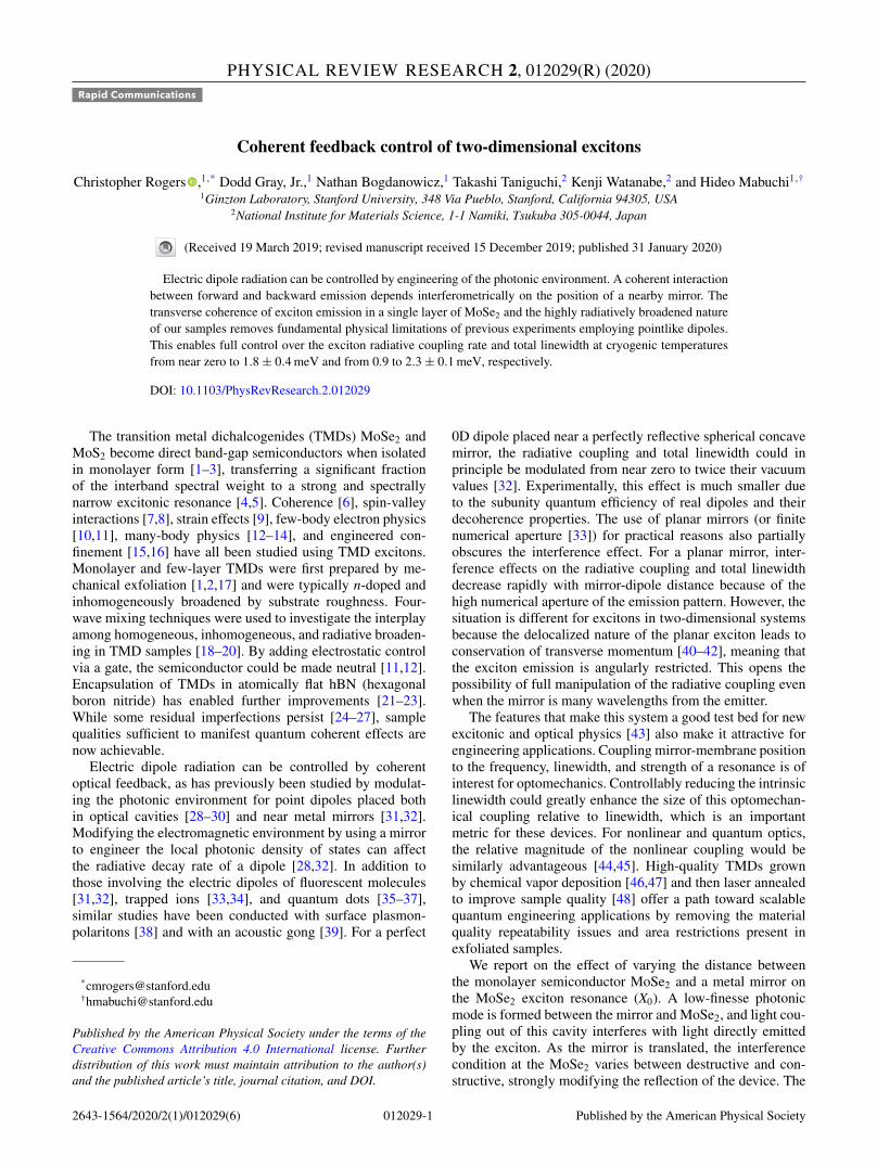
PHYSICAL REVIEW RESEARCH 2, 012029(R) (2020) Rapid Communications Coherent feedback control of two-dimensional excitons Christopher Rogers , 1, * Dodd Gray, Jr., 1 Nathan Bogdanowicz, 1 Takashi Taniguchi, 2 Kenji Watanabe, 2 and Hideo Mabuchi 1 , † 1 Ginzton Laboratory, Stanford University, 348 Via Pueblo, Stanford, California 94305, USA 2 National Institute for Materials Science, 1-1 Namiki, Tsukuba 305-0044, Japan (Received 19 March 2019; revised manuscript received 15 December 2019; published 31 January 2020) Electric dipole radiation can be controlled by engineering of the photonic environment. A coherent interaction between forward and backward emission depends interferometrically on the position of a nearby mirror. The transverse coherence of exciton emission in a single layer of MoSe 2 and the highly radiatively broadened nature of our samples removes fundamental physical limitations of previous experiments employing pointlike dipoles. This enables full control over the exciton radiative coupling rate and total linewidth at cryogenic temperatures from near zero to 1.8 ± 0.4 meV and from 0.9 to 2.3 ± 0.1 meV, respectively. DOI: 10.1103/PhysRevResearch.2.012029 The transition metal dichalcogenides (TMDs) MoSe 2 and MoS 2 become direct band-gap semiconductors when isolated in monolayer form [1–3], transferring a significant fraction of the interband spectral weight to a strong and spectrally narrow excitonic resonance [4,5]. Coherence [6], spin-valley interactions [7,8], strain effects [9], few-body electron physics [10,11], many-body physics [12–14], and engineered con- finement [15,16] have all been studied using TMD excitons. Monolayer and few-layer TMDs were first prepared by me- chanical exfoliation [1,2,17] and were typically n-doped and inhomogeneously broadened by substrate roughness. Four- wave mixing techniques were used to investigate the interplay among homogeneous, inhomogeneous, and radiative broaden- ing in TMD samples [18–20]. By adding electrostatic control via a gate, the semiconductor could be made neutral [11,12]. Encapsulation of TMDs in atomically flat hBN (hexagonal boron nitride) has enabled further improvements [21–23]. While some residual imperfections persist [24–27], sample qualities sufficient to manifest quantum coherent effects are now achievable. Electric dipole radiation can be controlled by coherent optical feedback, as has previously been studied by modulat- ing the photonic environment for point dipoles placed both in optical cavities [28–30] and near metal mirrors [31,32]. Modifying the electromagnetic environment by using a mirror to engineer the local photonic density of states can affect the radiative decay rate of a dipole [28,32]. In addition to those involving the electric dipoles of fluorescent molecules [31,32], trapped ions [33,34], and quantum dots [35–37], similar studies have been conducted with surface plasmon- polaritons [38] and with an acoustic gong [39]. For a perfect * [email protected] † [email protected] Published by the American Physical Society under the terms of the Creative Commons Attribution 4.0 International license. Further distribution of this work must maintain attribution to the author(s) and the published article’s title, journal citation, and DOI. 0D dipole placed near a perfectly reflective spherical concave mirror, the radiative coupling and total linewidth could in principle be modulated from near zero to twice their vacuum values [32]. Experimentally, this effect is much smaller due to the subunity quantum efficiency of real dipoles and their decoherence properties. The use of planar mirrors (or finite numerical aperture [33]) for practical reasons also partially obscures the interference effect. For a planar mirror, inter- ference effects on the radiative coupling and total linewidth decrease rapidly with mirror-dipole distance because of the high numerical aperture of the emission pattern. However, the situation is different for excitons in two-dimensional systems because the delocalized nature of the planar exciton leads to conservation of transverse momentum [40–42], meaning that the exciton emission is angularly restricted. This opens the possibility of full manipulation of the radiative coupling even when the mirror is many wavelengths from the emitter. The features that make this system a good test bed for new excitonic and optical physics [43] also make it attractive for engineering applications. Coupling mirror-membrane position to the frequency, linewidth, and strength of a resonance is of interest for optomechanics. Controllably reducing the intrinsic linewidth could greatly enhance the size of this optomechan- ical coupling relative to linewidth, which is an important metric for these devices. For nonlinear and quantum optics, the relative magnitude of the nonlinear coupling would be similarly advantageous [44,45]. High-quality TMDs grown by chemical vapor deposition [46,47] and then laser annealed to improve sample quality [48] offer a path toward scalable quantum engineering applications by removing the material quality repeatability issues and area restrictions present in exfoliated samples. We report on the effect of varying the distance between the monolayer semiconductor MoSe 2 and a metal mirror on the MoSe 2 exciton resonance (X 0 ). A low-finesse photonic mode is formed between the mirror and MoSe 2 , and light cou- pling out of this cavity interferes with light directly emitted by the exciton. As the mirror is translated, the interference condition at the MoSe 2 varies between destructive and con- structive, strongly modifying the reflection of the device. The 2643-1564/2020/2(1)/012029(6) 012029-1 Published by the American Physical Society

Welcome message from author
This document is posted to help you gain knowledge. Please leave a comment to let me know what you think about it! Share it to your friends and learn new things together.
Transcript
PHYSICAL REVIEW RESEARCH 2, 012029(R) (2020)Rapid Communications
Coherent feedback control of two-dimensional excitons
Christopher Rogers ,1,* Dodd Gray, Jr.,1 Nathan Bogdanowicz,1 Takashi Taniguchi,2 Kenji Watanabe,2 and Hideo Mabuchi1,†
1Ginzton Laboratory, Stanford University, 348 Via Pueblo, Stanford, California 94305, USA2National Institute for Materials Science, 1-1 Namiki, Tsukuba 305-0044, Japan
(Received 19 March 2019; revised manuscript received 15 December 2019; published 31 January 2020)
Electric dipole radiation can be controlled by engineering of the photonic environment. A coherent interactionbetween forward and backward emission depends interferometrically on the position of a nearby mirror. Thetransverse coherence of exciton emission in a single layer of MoSe2 and the highly radiatively broadened natureof our samples removes fundamental physical limitations of previous experiments employing pointlike dipoles.This enables full control over the exciton radiative coupling rate and total linewidth at cryogenic temperaturesfrom near zero to 1.8 ± 0.4 meV and from 0.9 to 2.3 ± 0.1 meV, respectively.
DOI: 10.1103/PhysRevResearch.2.012029
The transition metal dichalcogenides (TMDs) MoSe2 andMoS2 become direct band-gap semiconductors when isolatedin monolayer form [1–3], transferring a significant fractionof the interband spectral weight to a strong and spectrallynarrow excitonic resonance [4,5]. Coherence [6], spin-valleyinteractions [7,8], strain effects [9], few-body electron physics[10,11], many-body physics [12–14], and engineered con-finement [15,16] have all been studied using TMD excitons.Monolayer and few-layer TMDs were first prepared by me-chanical exfoliation [1,2,17] and were typically n-doped andinhomogeneously broadened by substrate roughness. Four-wave mixing techniques were used to investigate the interplayamong homogeneous, inhomogeneous, and radiative broaden-ing in TMD samples [18–20]. By adding electrostatic controlvia a gate, the semiconductor could be made neutral [11,12].Encapsulation of TMDs in atomically flat hBN (hexagonalboron nitride) has enabled further improvements [21–23].While some residual imperfections persist [24–27], samplequalities sufficient to manifest quantum coherent effects arenow achievable.
Electric dipole radiation can be controlled by coherentoptical feedback, as has previously been studied by modulat-ing the photonic environment for point dipoles placed bothin optical cavities [28–30] and near metal mirrors [31,32].Modifying the electromagnetic environment by using a mirrorto engineer the local photonic density of states can affectthe radiative decay rate of a dipole [28,32]. In addition tothose involving the electric dipoles of fluorescent molecules[31,32], trapped ions [33,34], and quantum dots [35–37],similar studies have been conducted with surface plasmon-polaritons [38] and with an acoustic gong [39]. For a perfect
*[email protected]†[email protected]
Published by the American Physical Society under the terms of theCreative Commons Attribution 4.0 International license. Furtherdistribution of this work must maintain attribution to the author(s)and the published article’s title, journal citation, and DOI.
0D dipole placed near a perfectly reflective spherical concavemirror, the radiative coupling and total linewidth could inprinciple be modulated from near zero to twice their vacuumvalues [32]. Experimentally, this effect is much smaller dueto the subunity quantum efficiency of real dipoles and theirdecoherence properties. The use of planar mirrors (or finitenumerical aperture [33]) for practical reasons also partiallyobscures the interference effect. For a planar mirror, inter-ference effects on the radiative coupling and total linewidthdecrease rapidly with mirror-dipole distance because of thehigh numerical aperture of the emission pattern. However, thesituation is different for excitons in two-dimensional systemsbecause the delocalized nature of the planar exciton leads toconservation of transverse momentum [40–42], meaning thatthe exciton emission is angularly restricted. This opens thepossibility of full manipulation of the radiative coupling evenwhen the mirror is many wavelengths from the emitter.
The features that make this system a good test bed for newexcitonic and optical physics [43] also make it attractive forengineering applications. Coupling mirror-membrane positionto the frequency, linewidth, and strength of a resonance is ofinterest for optomechanics. Controllably reducing the intrinsiclinewidth could greatly enhance the size of this optomechan-ical coupling relative to linewidth, which is an importantmetric for these devices. For nonlinear and quantum optics,the relative magnitude of the nonlinear coupling would besimilarly advantageous [44,45]. High-quality TMDs grownby chemical vapor deposition [46,47] and then laser annealedto improve sample quality [48] offer a path toward scalablequantum engineering applications by removing the materialquality repeatability issues and area restrictions present inexfoliated samples.
We report on the effect of varying the distance betweenthe monolayer semiconductor MoSe2 and a metal mirror onthe MoSe2 exciton resonance (X0). A low-finesse photonicmode is formed between the mirror and MoSe2, and light cou-pling out of this cavity interferes with light directly emittedby the exciton. As the mirror is translated, the interferencecondition at the MoSe2 varies between destructive and con-structive, strongly modifying the reflection of the device. The
2643-1564/2020/2(1)/012029(6) 012029-1 Published by the American Physical Society

CHRISTOPHER ROGERS et al. PHYSICAL REVIEW RESEARCH 2, 012029(R) (2020)
MoSe2
SiO2
graphene
FIG. 1. Sample characterization. (a) A schematic of the het-erostructure device. The Au mirror is mounted on a mechanicalactuator so that z can be varied. (b) A microscope image of thesample. The monolayer MoSe2 region is outlined in burgundy. Afew-layer graphene flake outlined in black on the bottom of the stackelectrostatically isolates the MoSe2 from the SiO2 substrate. Thebottom hBN is outlined in blue. (c) Spatial maps of the maximumdip in reflection at X0, and its center wavelength λX0 from a regionof the sample corresponding to the area outlined with dashed whitelines in panel (b). (d) Selected reflection spectra corresponding to themarked positions in panel (c). These spectra were collected at 4 Kwith the mirror positioned slightly away from maximum destructiveinterference.
magnitude of the reflection at X0 can vary from near zeroto near unity, and the absorption varies in a complementaryway. This interference condition also affects the radiativecoupling of X0 to the environment, and at maximal destructiveinterference the coupling can be almost entirely suppressed, intheory limited only by mirror losses. Conversely, at maximalconstructive interference, this coupling is twice its vacuumvalue. Since X0 is primarily radiatively broadened (a ratioof up to 3:1 in our samples, enabled by recent advances intwo-dimensional [2D] material sample fabrication [21–23]),this modulation of the radiative coupling from near zero to1.8 ± 0.4 meV induces a similar effect on the total linewidthfrom 0.9 to 2.3 ± 0.1 meV.
We fabricate heterostructures of MoSe2 encapsulated inhBN and then transfer these stacks onto fused silica substrates[49,50]. A microscope image of the sample used for the datapresented in this paper is shown in Fig. 1(b), and a schematicof the experiment is shown in Fig. 1(a). Experiments areconducted within an optical cryostat at 4 K. A gold mirror on amechanical actuator is placed in close proximity to the MoSe2
heterostructure. The mirror is translated along the optical axis,and at selected z positions reflectance measurements are madeusing a grating spectrometer. Measurements were automatedusing the PYTHON instrument control package Instrumental[51]. Note that z is the optical path length between the mirrorand the MoSe2. This method of mirror translation isolates theeffect of coherent electromagnetic feedback since it is entirelyfree of coupling to strain or electric field in the TMD. Moreexperimental details can be found in Ref. [52]. Because we
excite with ∼15 nW of optical power, the excitation occupa-tion number during the measurement is very low, ∼10−3 [52].Thus, our experiments correspond to probing radiative reac-tion in the regime of perturbative quantum electrodynamics[53].
Maps of the magnitude of the dip in reflectance at X0 andits center frequency and wavelength (ωX0 , λX0 ) are shown inFig. 1(c). The mirror is near but not at maximum destructiveinterference. As observed by others [21,22], there is inhomo-geneity on a few-micron scale in both λX0 and the magnitudeof the reflection. Nonetheless, some areas of the sample areradiatively broadened. In Fig. 1(d), spots are selected to showboth a range of sample quality and λX0 .
A heat map of the reflectance as a function of mirrorposition is shown in Fig. 2(a), along with selected line cutsof the same data in Fig. 2(c). The X0 resonance appears as adip (the central bright band) that varies in magnitude, width,and center frequency as the mirror is translated across a fullfringe. We define zd and zc as the mirror positions for maximaldestructive and constructive interference respectively, as inFig. 2(b). When the reflection from the mirror interferes de-structively with that from the MoSe2, the radiative coupling ofX0 becomes very small and the dip disappears below the noisefloor [zd,1 and zd,2 in Fig. 2(a)]. Surprisingly, the minimumreflection over z does not occur at zc, but rather occurs ateach of two mirror positions on either side of zc. At these tworeflection minima (zm,1 = 835 nm and zm,2 = 1015 nm), thereflectance is ≈6%, while in between it reaches 43% at zc.
This surprising effect is due to an interplay between the ra-diative coupling rate (γr) and nonradiative coupling rate (γnr).At zc, constructive interference leads to maximal radiativebroadening. Here, the exciton is primarily radiatively broad-ened and γr is larger than γnr + γib,eff . We define γtot = γr +γnr + γib,eff as the total linewidth, where γib,eff is the effectivecontribution to the total linewidth from a constant Gaussianinhomogeneous broadening γib. Please see Refs. [52,54,55]for more details of the subtle difference between γib andγib,eff . For most purposes, γib and γib,eff can be thought of asequivalent.
We note that in an ideal material (γr � γnr, γib,eff ) thereflectance feature at zc would be very small and the mini-mum reflectance would approach unity. However, in our realsample, γnr and γib,eff increase the depth of the reflectancefeature at zc so that the minimum reflectance is 43%. Thisoccurs because the intrinsic reflectivity of the exciton isa metric of the ratio γr/γtot [22]. As this ratio increases,the intrinsic reflectivity of the exciton becomes higher andthe reflectance feature becomes smaller. When the mirror ismoved in either direction from zc, the decrease in γr causesthe ratio γr/γnr to be reduced. This causes the exciton toabsorb more light, and the reflectance feature deepens untilreaching its minimum value at zm,1/2. At zm,1/2, impedancematching leads to a maximum absorption of near unity. Theexciton also begins to spectrally narrow, since the contributionof γr to the total linewidth is reduced. As the mirror is movedpast zm,1/2 and toward destructive interference at zd,1/2, γr
continues to decrease. This causes the X0 feature to shrink andspectrally narrow until it eventually disappears. Near zd,1/2,the total linewidth is dominated by γnr and γib,eff , so thatγtot ≈ γnr + γib,eff .
012029-2

COHERENT FEEDBACK CONTROL OF TWO-DIMENSIONAL … PHYSICAL REVIEW RESEARCH 2, 012029(R) (2020)
(a) (b)
(c)(d)
FIG. 2. Experimental and modeled reflectance. (a) Measured and modeled reflectance spectra near the X0 resonance as z is varied over afull fringe. Measurements at 4 K. Note that these data come from near the region marked with a purple circle in Fig. 1(c). (b) A schematicrepresentation of the effect of mirror position z on the the exciton resonance. The black double-headed arrow represents the exciton electricdipole, and the blue and orange curves represent the electric field emitted toward and away from the mirror, respectively. The electric fieldreflected by the mirror is represented in green. To the right of the monolayer, the fields interfere either constructively or destructively dependingon mirror position. The corresponding schematic plots represent the modulation of amplitude and linewidth of the X0 feature. The zd and zc
values, shown for the destructive and constructive interference cases respectively, assume a perfect mirror with zero skin depth. For simplicity,multiple reflections and the full heterostructure have been omitted. (c) Selected line cuts of the measured and modeled reflectance in the spectralregion of X0. The black arrows indicate increasing z. (d) Measured reflectance, both absolute and normalized, at two z positions highlightingthe modulation of total linewidth.
Note that the center frequency ωX0 of the dip changes withmirror position as well. When the light reflected from themirror is exactly in or out of phase with that back-emittedfrom the MoSe2, the dip is at its vacuum frequency (ω0),and ωX0 = ω0. However, away from either of these positions,dispersion over the X0 resonance causes a spectrally asym-metric interference condition, which shifts the effective linecenter ωX0 .
We model the TMD exciton using a Lorentzian suscepti-bility, which accounts for radiative broadening γr and nonra-diative broadening γnr [22,56]:
χexc = − c
ω0d
γr,0
ω − ω0 + iγnr
2
, (1)
where ω0 is the exciton vacuum center frequency, ω is theoptical frequency, c is the speed of light, and d is the MoSe2
thickness. The homogeneous reflectance Rω0 (ω) is calculatedfor the full heterostructure and mirror stack using a transfer
matrix method [57]. Inhomogeneous broadening effects areincluded by convolving Rω0 (ω) with a Gaussian of character-istic width γib to obtain the full reflectance R(ω). Selected linecuts and their z positions were simultaneously fit to this modelto find global values for γr , γnr , γib, and ωX0 ; see Ref. [52]for more details. Plots of the modeled reflectance are shownin Figs. 2(a) and 2(c). Both qualitatively and quantitativelythe model matches closely with the experimental data. SeeRef. [52] for a discussion of the small discrepancies, anestimate of the uncertainty in the fitted parameters, and acomparison of two different methods for extracting the zposition.
From both the experimental data and the model, we ex-tract full-width-half-maximum (FWHM) linewidths, whichare shown in Fig. 3(a). As a function of mirror position, thelinewidth γtot varies from ∼0.9 meV near zd to ∼2.3 meVat zc for a total modulation of ∼2.5×, while in the modelit varies from 0.9 to 2.4 meV, or ∼2.6×. This modulation
012029-3

CHRISTOPHER ROGERS et al. PHYSICAL REVIEW RESEARCH 2, 012029(R) (2020)
(a)
(b)
(c)
(d)
)
FIG. 3. Extracted and modeled linewidths. (a) The FWHMlinewidth γtot both from the model and extracted from the exper-imental data. Note that we cannot extract linewidth data over thefull range of the experimental data, since near zd the X0 resonanceis almost completely extinguished. Also shown are γr and γnr fromthe model. (b) Center frequency ωX0 for both model and experiment.(c) Minimum reflectance for both model and experiment. The shad-ing in panels (a)–(c) represents the uncertainties in the model; seeRef. [52]. (d) Simplified models of the total linewidth modulation forboth a point and 2D dipole, assuming a perfect mirror with zero skindepth. The top panel shows the ideal case with coherent quantumefficiency in vacuum η0 = 1, and the bottom panel shows the casewith η0 = 0.45. Both are shown alongside the experimental data.
can also be clearly seen in Fig. 2(d). The change in γr ofthe X0 resonance is the primary cause of the change in γtot,and the values of γr extracted from the model vary fromnear zero at zd to 1.8 ± 0.4 meV (440 ± 100 GHz) at zc. Nearzd , γtot is dominated by the contribution of γnr and γib,eff ,while at zc, radiative coupling dominates, with a ratio ofγr/(γnr + γib,eff ) ∼ 3.
Modeled and experimental values for ωX0 and the minimumreflectance shown in Figs. 3(b) and 3(c) agree as well. The lineshift of ≈1 meV (240 GHz) is significant relative to γtot.
Lastly, in Fig. 3(d) we compare our data to a simplifiedmodel of both a 2D dipole and a point dipole. The 2Dcase highlights that the transverse coherence and delocalizednature of the exciton causes light emission into specific modesrather than the full numerical aperture. We define the coherentquantum efficiency in vacuum η0 = γr,0/γtot, which differsfrom the incoherent quantum efficiency γr,0/(γr,0 + γnr ). Forour purpose, η0 is the relevant quantity because the linewidthmodulation effect depends on the coherent interference ofemitted waves. For a 2D dipole, the total linewidth γtot (x) as afunction of normalized mirror position x = 4πz
λ0is [52]
γtot (x)
γtot,0= 1 − η0 cos x, (2)
where γtot,0 is the total linewidth in vacuum and λ0 is thewavelength in vacuum. The equivalent expression for a 0Ddipole is given in Ref. [52].
It is clear that for an ideal 2D dipole (η0 = 1) and aperfect planar mirror, the linewidth can be fully modulatedeven when the mirror is far from the dipole. This is not truein the 0D dipole case, because integrating emission over thefull numerical aperture obscures the interference effect as zincreases. Also shown is a plot for η0 = 0.45 chosen to matchthe superimposed experimental data.
As can be seen clearly in Fig. 3(d), no 0D dipole in frontof a flat mirror (even with a perfect mirror and η0 = 1) couldproduce the behavior seen in the experiments. While defectsand inhomogeneity likely prevent the excitons from beingdelocalized over the entire excitation area, the amplitude andphase of the experimental γtot is strong evidence that they aredelocalized on a length scale of the same order as the opticalwavelength.
We have demonstrated coherent control over an excitonresonance by positioning a mirror in close proximity to themonolayer semiconductor MoSe2, showing near completemodulation of the reflection at X0. The concurrent changein radiative coupling rate induces a change in total linewidthof ∼2.5×, demonstrating the dominant role of radiative cou-pling for excitons in monolayer MoSe2 and serving as animportant verification of theoretical models used to describeexcitonic physics in TMD materials. For engineering appli-cations, the modulation of the X0 resonance could greatlyenhance optomechanical couplings, while the effective en-hancement of nonlinearities [44] is useful for nonlinear opticsand quantum optics. Our strain-free and DC-electric-field-freemethod of mirror positioning has allowed us to study theunderlying photonic interference effect present in the system,and the unprecedented control over the radiative couplingof an excitonic resonance paves the way for many futureexperiments.
Note added. During preparation of this paper, we becameaware of preprints presenting similar work by Y. Zhou et al.[58], H. H. Fang et al. [59], and J. Horng et al. [60]. SeeRef. [52] for a short discussion of where the results presentedhere fit in the context of these similar works.
This work was funded in part by the National ScienceFoundation (NSF) Awards No. PHY-1648807 and No. DMR-1838497 and also by a seed grant from the Precourt Institutefor Energy at Stanford University. Part of this work wasperformed at the Stanford Nano Shared Facilities (SNSF),supported by the NSF under Award No. ECCS-1542152.C.R., D.G., and N.B. were supported in part by StanfordGraduate Fellowships. C.R. was also supported in part bya Natural Sciences and Engineering Research Council ofCanada doctoral postgraduate scholarship. K.W. and T.T.acknowledge support from the Elemental Strategy Initiativeconducted by the MEXT, Japan, and and the CREST (JP-MJCR15F3), JST. All authors thank Tatsuhiro Onodera fordiscussions relating to the reflectance model. All authorsthank Daniel B. S. Soh and Eric Chatterjee for discussionsrelating to exciton physics. C.R. thanks Joe Finney, Gio-vanni Scuri, and Elyse Barre for help with heterostructurefabrication, Logan Wright for pointing out relevant litera-
012029-4

COHERENT FEEDBACK CONTROL OF TWO-DIMENSIONAL … PHYSICAL REVIEW RESEARCH 2, 012029(R) (2020)
ture, and Peter L. McMahon for suggestions relating to themanuscript. C.R. conceived the experiments, fabricated thesamples, performed the experiments, and performed the dataanalysis. C.R. and D.G. built the confocal microscope setup
for the cryostat, as well as the grating spectrometer. C.R.and N.B. automated the measurements. T.T. and K.W. grewthe hBN. C.R., N.B., D.G., and H.M. all contributed to themanuscript.
[1] K. F. Mak, C. Lee, J. Hone, J. Shan, and T. F. Heinz, AtomicallyThin MoS2: A New Direct-Gap Semiconductor, Phys. Rev. Lett.105, 136805 (2010).
[2] A. Splendiani, L. Sun, Y. Zhang, T. Li, J. Kim, C.-Y. Chim, G.Galli, and F. Wang, Emerging photoluminescence in monolayerMoS2, Nano Lett. 10, 1271 (2010).
[3] Y. Zhang, T.-R. Chang, B. Zhou, Y.-T. Cui, H. Yan, Z. Liu, F.Schmitt, J. Lee, R. Moore, Y. Chen, H. Lin, H.-T. Jeng, S.-K.Mo, Z. Hussain, A. Bansil, and Z.-X. Shen, Direct observationof the transition from indirect to direct bandgap in atomicallythin epitaxial MoSe2, Nat. Nanotechnol. 9, 111 (2013).
[4] A. Molina-Sánchez, D. Sangalli, K. Hummer, A. Marini, andL. Wirtz, Effect of spin-orbit interaction on the optical spectraof single-layer, double-layer, and bulk MoS2, Phys. Rev. B 88,045412 (2013).
[5] A. Molina-Sánchez, M. Palummo, A. Marini, and L. Wirtz,Temperature-dependent excitonic effects in the optical proper-ties of single-layer MoS2, Phys. Rev. B 93, 155435 (2016).
[6] A. M. Jones, H. Yu, N. J. Ghimire, S. Wu, G. Aivazian, J. S.Ross, B. Zhao, J. Yan, D. G. Mandrus, D. Xiao, W. Yao, andX. Xu, Optical generation of excitonic valley coherence inmonolayer WSe2, Nat. Nanotechnol. 8, 634 (2013).
[7] D. Xiao, G.-B. Liu, W. Feng, X. Xu, and W. Yao, Coupled Spinand Valley Physics in Monolayers of MoS2 and Other Group-VIDichalcogenides, Phys. Rev. Lett. 108, 196802 (2012).
[8] K. F. Mak, K. He, J. Shan, and T. F. Heinz, Control of val-ley polarization in monolayer MoS2 by optical helicity, Nat.Nanotechnol. 7, 494 (2012).
[9] H. J. Conley, B. Wang, J. I. Ziegler, R. F. Haglund, S. T.Pantelides, and K. I. Bolotin, Bandgap engineering of strainedmonolayer and bilayer MoS2, Nano Lett. 13, 3626 (2013).
[10] Y. You, X.-X. Zhang, T. C. Berkelbach, M. S. Hybertsen,D. R. Reichman, and T. F. Heinz, Observation of biexcitons inmonolayer WSe2, Nat. Phys. 11, 477 (2015).
[11] K. F. Mak, K. He, C. Lee, G. H. Lee, J. Hone, T. F. Heinz, andJ. Shan, Tightly bound trions in monolayer MoS2, Nat. Mater.12, 207 (2012).
[12] M. Sidler, P. Back, O. Cotlet, A. Srivastava, T. Fink, M. Kroner,E. Demler, and A. Imamoglu, Fermi polaron-polaritons incharge-tunable atomically thin semiconductors, Nat. Phys. 13,255 (2016).
[13] D. Van Tuan, B. Scharf, Z. Wang, J. Shan, K. F. Mak, I.Žutic, and H. Dery, Probing many-body interactions in mono-layer transition-metal dichalcogenides, Phys. Rev. B 99, 085301(2019).
[14] A. Steinhoff, T. O. Wehling, and M. Rösner, Frequency-dependent substrate screening of excitons in atomically thintransition metal dichalcogenide semiconductors, Phys. Rev. B98, 045304 (2018).
[15] K. Wang, K. De Greve, L. A. Jauregui, A. Sushko, A. High,Y. Zhou, G. Scuri, T. Taniguchi, K. Watanabe, M. D. Lukin,H. Park, and P. Kim, Electrical control of charged carriers and
excitons in atomically thin materials, Nat. Nanotechnol. 13, 128(2018).
[16] C. Palacios-Berraquero, D. M. Kara, A. R. P Montblanch, M.Barbone, P. Latawiec, D. Yoon, A. K. Ott, M. Loncar, A. C.Ferrari, and M. Atatüre, Large-scale quantum-emitter arraysin atomically thin semiconductors, Nat. Commun. 8, 15093(2017).
[17] R. F. Frindt, Optical absorption of a few unit-cell layers ofMoS2, Phys. Rev. 140, A536 (1965).
[18] P. Dey, J. Paul, Z. Wang, C. E. Stevens, C. Liu, A. H. Romero,J. Shan, D. J. Hilton, and D. Karaiskaj, Optical Coherence inAtomic-Monolayer Transition-Metal Dichalcogenides Limitedby Electron-Phonon Interactions, Phys. Rev. Lett. 116, 127402(2016).
[19] T. Jakubczyk, V. Delmonte, M. Koperski, K. Nogajewski, C.Faugeras, W. Langbein, M. Potemski, and J. Kasprzak, Ra-diatively limited dephasing and exciton dynamics in MoSe2monolayers revealed with four-wave mixing microscopy, NanoLett. 16, 5333 (2016).
[20] K. Hao, L. Xu, P. Nagler, A. Singh, K. Tran, C. K. Dass,C. Schüller, T. Korn, X. Li, and G. Moody, Coherent andincoherent coupling dynamics between neutral and chargedexcitons in monolayer MoSe2, Nano Lett. 16, 5109 (2016).
[21] F. Cadiz, E. Courtade, C. Robert, G. Wang, Y. Shen, H. Cai,T. Taniguchi, K. Watanabe, H. Carrere, D. Lagarde, M. Manca,T. Amand, P. Renucci, S. Tongay, X. Marie, and B. Urbaszek,Excitonic linewidth approaching the homogeneous limit inMoS2-based van der Waals heterostructures, Phys. Rev. X 7,021026 (2017).
[22] G. Scuri, Y. Zhou, A. A. High, D. S. Wild, C. Shu, K. De Greve,L. A. Jauregui, T. Taniguchi, K. Watanabe, P. Kim, M. D. Lukin,and H. Park, Large Excitonic Reflectivity of Monolayer MoSe2
Encapsulated in Hexagonal Boron Nitride, Phys. Rev. Lett. 120,037402 (2018).
[23] P. Back, S. Zeytinoglu, A. Ijaz, M. Kroner, and A. Imamoglu,Realization of an Electrically Tunable Narrow-BandwidthAtomically Thin Mirror Using Monolayer MoSe2, Phys. Rev.Lett. 120, 037401 (2018).
[24] L. Mennel, M. M. Furchi, S. Wachter, M. Paur, D. K.Polyushkin, and T. Mueller, Optical imaging of strain in two-dimensional crystals, Nat. Commun. 9, 516 (2018).
[25] J. Hong, Z. Hu, M. Probert, K. Li, D. Lv, X. Yang, L. Gu, N.Mao, Q. Feng, L. Xie, J. Zhang, D. Wu, Z. Zhang, C. Jin, W.Ji, X. Zhang, J. Yuan, and Z. Zhang, Exploring atomic defectsin molybdenum disulphide monolayers, Nat. Commun. 6, 6293(2015).
[26] H. Wang, C. Zhang, and F. Rana, Ultrafast dynamics of defect-assisted electron-hole recombination in monolayer MoS2, NanoLett. 15, 339 (2015).
[27] J. Xue, J. Sanchez-Yamagishi, D. Bulmash, P. Jacquod, A.Deshpande, K. Watanabe, T. Taniguchi, P. Jarillo-Herrero, andB. J. LeRoy, Scanning tunnelling microscopy and spectroscopy
012029-5

CHRISTOPHER ROGERS et al. PHYSICAL REVIEW RESEARCH 2, 012029(R) (2020)
of ultra-flat graphene on hexagonal boron nitride, Nat. Mater.10, 282 (2011).
[28] E. M. Purcell, H. C. Torrey, and R. V. Pound, Resonanceabsorption by nuclear magnetic moments in a solid, Phys. Rev.69, 37 (1946).
[29] D. J. Heinzen, J. J. Childs, J. E. Thomas, and M. S. Feld, En-hanced and Inhibited Visible Spontaneous Emission by Atomsin a Confocal Resonator, Phys. Rev. Lett. 58, 1320 (1987).
[30] A. M. Vredenberg, N. E. J. Hunt, E. F. Schubert, D. C. Jacobson,J. M. Poate, and G. J. Zydzik, Controlled Atomic SpontaneousEmission from Er3+ in a Transparent Si/SiO2 Microcavity,Phys. Rev. Lett. 71, 517 (1993).
[31] K. H. Drexhage, H. Kuhn, and F. P. Schäfer, Variation of thefluorescence decay time of a molecule in front of a mirror, Ber.Bunsengesellsch. Phys. Chem. 72, 329 (1968).
[32] K. H. Drexhage, Influence of a dielectric interface on fluores-cence decay time, J. Lumin. 1–2, 693 (1970).
[33] J. Eschner, C. Raab, F. Schmidt-Kaler, and R. Blatt, Lightinterference from single atoms and their mirror images, Nature(London) 413, 495 (2001).
[34] M. A. Wilson, P. Bushev, J. Eschner, F. Schmidt-Kaler, C.Becher, R. Blatt, and U. Dorner, Vacuum-Field Level Shifts in aSingle Trapped Ion Mediated by a Single Distant Mirror, Phys.Rev. Lett. 91, 213602 (2003).
[35] S. Stobbe, J. Johansen, P. T. Kristensen, J. M. Hvam, andP. Lodahl, Frequency dependence of the radiative decay rateof excitons in self-assembled quantum dots: Experiment andtheory, Phys. Rev. B 80, 155307 (2009).
[36] M. L. Andersen, S. Stobbe, A. S. Sørensen, and P. Lodahl,Strongly modified plasmon-matter interaction with mesoscopicquantum emitters, Nat. Phys. 7, 215 (2011).
[37] P. Tighineanu, M. L. Andersen, A. S. Sørensen, S. Stobbe, andP. Lodahl, Probing Electric and Magnetic Vacuum Fluctuationswith Quantum Dots, Phys. Rev. Lett. 113, 043601 (2014).
[38] R. Brechbühler, F. T. Rabouw, P. Rohner, B. le Feber, D.Poulikakos, and D. J. Norris, Two-Dimensional Drexhage Ex-periment for Electric- and Magnetic-Dipole Sources on Plas-monic Interfaces, Phys. Rev. Lett. 121, 113601 (2018).
[39] L. Langguth, R. Fleury, A. Alù, and A. F. Koenderink, Drex-hage’s Experiment for Sound, Phys. Rev. Lett. 116, 224301(2016).
[40] H. Wang, C. Zhang, W. Chan, C. Manolatou, S. Tiwari, and F.Rana, Radiative lifetimes of excitons and trions in monolayersof the metal dichalcogenide MoS2, Phys. Rev. B 93, 045407(2016).
[41] D. B. S. Soh, C. Rogers, D. J. Gray, E. Chatterjee, andH. Mabuchi, Optical nonlinearities of excitons in monolayerMoS2, Phys. Rev. B 97, 165111 (2018).
[42] M. Sugawara, Theory of spontaneous-emission lifetime ofwannier excitons in mesoscopic semiconductor quantum disks,Phys. Rev. B 51, 10743 (1995).
[43] T. Byrnes, N. Y. Kim, and Y. Yamamoto, Exciton-polaritoncondensates, Nat. Phys. 10, 803 (2014).
[44] D. S. Wild, E. Shahmoon, S. F. Yelin, and M. D. Lukin,Quantum Nonlinear Optics in Atomically Thin Materials, Phys.Rev. Lett. 121, 123606 (2018).
[45] S. Zeytinoglu, C. Roth, S. Huber, and A. Imamoglu, Atomicallythin semiconductors as nonlinear mirrors, Phys. Rev. A 96,031801(R) (2017).
[46] Y. Yu, C. Li, Y. Liu, L. Su, Y. Zhang, and L. Cao, Controlledscalable synthesis of uniform, high-quality monolayer and few-layer MoS2 films, Sci. Rep. 3, 1866 (2013).
[47] Y.-H Lee, X.-Q. Zhang, W. Zhang, M.-T. Chang, C.-T. Lin,K.-D. Chang, Y.-C. Yu, J. T.-W. Wang, C.-S. Chang, L.-J.Li, and T.-W. Lin, Synthesis of large-area MoS2 atomic lay-ers with chemical vapor deposition, Adv. Mater. 24, 2320(2012).
[48] C. Rogers, D. Gray, N. Bogdanowicz, and H. Mabuchi, Laserannealing for radiatively broadened MoSe2 grown by chemicalvapor deposition, Phys. Rev. Mat. 2, 094003 (2018).
[49] P. J. Zomer, M. H. D. Guimarães, J. C. Brant, N. Tombros, andB. J. van Wees, Fast pick up technique for high quality het-erostructures of bilayer graphene and hexagonal boron nitride,Appl. Phys. Lett. 105, 013101 (2014).
[50] F. Pizzocchero, L. Gammelgaard, B. S. Jessen, J. M. Caridad,L. Wang, J. Hone, P. Bøggild, and T. J. Booth, The hot pick-uptechnique for batch assembly of van der Waals heterostructures,Nat. Commun. 7, 11894 (2016).
[51] N. Bogdanowicz, C. Rogers, D. Gray, C. Timossi, F. Marazzi,J. Wheeler, and I. Galinskiy, mabuchilab/Instrumental: 0.5,version 0.5 (2018), http://doi.org/10.5281/zenodo.2556399
[52] See Supplemental Material at http://link.aps.org/supplemental/10.1103/PhysRevResearch.2.012029 for additional experimen-tal methods and details of the reflectance model and fittingprocedures.
[53] D. Meschede, W. Jhe, and E. A. Hinds, Radiative properties ofatoms near a conducting plane: An old problem in a new light,Phys. Rev. A 41, 1587 (1990).
[54] Y. Liu, J. Lin, G. Huang, Y. Guo, and C. Duan, Simple empiricalanalytical approximation to the Voigt profile, J. Opt. Soc. Am.B 18, 666 (2001).
[55] J. J. Olivero and R. L. Longbothum, Empirical fits to the Voigtline width: A brief review, J. Quant. Spectrosc. Radiat. Transfer17, 233 (1977).
[56] F. Wooten, Optical Properties of Solids (Academic Press, SanDiego, 1972), Chap. 3.
[57] C. C. Katsidis and D. I. Siapkas, General transfer-matrixmethod for optical multilayer systems with coherent, partiallycoherent, and incoherent interference, Appl. Opt. 41, 3978(2002).
[58] Y. Zhou, G. Scuri, J. Sung, R. J. Gelly, D. S. Wild, K. De Greve,A. Y. Joe, T. Taniguchi, K. Watanabe, P. Kim, M. D. Lukin, andH. Park, Controlling excitons in an atomically thin membranewith a mirror, Phys. Rev. Lett. 124, 027401 (2020).
[59] H. H. Fang, B. Han, C. Robert, M. A. Semina, D. Lagarde, E.Courtade, T. Taniguchi, K. Watanabe, T. Amand, B. Urbaszek,M. M. Glazov, and X. Marie, Control of the Exciton RadiativeLifetime in Van Der Waals Heterostructures, Phys. Rev. Lett.123, 067401 (2019).
[60] J. Horng, Y.-H. Chou, T.-C. Chang, C.-Y. Hsu, T.-C. Lu, andH. Deng, Engineering radiative coupling of excitons in 2dsemiconductors, Optica 6, 1443 (2019).
012029-6
Related Documents