POWER ELECTRONICS AND DRIVES Vol. 1(36), No. 1, 2016 DOI: 10.5277/PED160112 PHYSICAL PHENOMENA EXISTING IN THE TURBOGENERATOR DURING FAULTY SYNCHRONIZATION WITH INVERSE PHASE SEQUENCE* ADAM GOZDOWIAK, PIOTR KISIELEWSKI, LUDWIK ANTAL Wrocław University of Science and Technology, Department of Electrical Machines, Drives and Measurements, Wybrzeże Wyspiańskiego 27, 50-370 Wrocław, Poland, e-mail: [email protected], [email protected], [email protected] Abstract: The present paper shows the simulation results of turbogenerator faulty synchronization with inverse phase sequence. Great emphasis is placed on the physical phenomena existing in the rotor because the measurement of rotor damper bar currents is difficult in practice. There are presented the comparisons of maximum magnitudes of stator current and electromagnetic torque determined during faulty synchroni- zation with maximum magnitudes designated during sudden short circuit after both no-load and rated op- eration condition. In addition, the effect of synchronizing limits on faulty synchronization is presented. Keywords: turbogenerator, faulty synchronization, inverse phase sequence, finite element method 1. INTRODUCTION An occurrence of faulty turbogenerator synchronization is probable [1], [2]. The most dangerous case is faulty synchronization with inverse phase sequence. This incident can occur when one phase is connected correctly and is used only in synchronization device whereas the rest of two phases are inversely connected on account of a change in installation. Another reason is whether the cords coming to synchronization device are connected to incorrect terminals. This accident could happen after some modifica- tions inside the installation without performing inspection. Synchronization of turbogenerator to the grid must be performed carefully. The rotor speed and terminal voltages of isolated turbogenerator must be closely matched. Whereas stator voltage phase angle must be close to the instantaneous grid voltage phase angle prior to closing the breaker to connect the isolated turbogenerator to the grid. Poor synchronizing can cause the following dangerous incidents: – damage to the turbogenerator and step-up transformer windings caused by high currents which are significantly above the acceptable limits, * Manuscript received: March 30, 2016; accepted: June 27, 2016.

Welcome message from author
This document is posted to help you gain knowledge. Please leave a comment to let me know what you think about it! Share it to your friends and learn new things together.
Transcript

POWER ELECTRONICS AND DRIVESVol. 1(36), No. 1, 2016 DOI: 10.5277/PED160112
PHYSICAL PHENOMENA EXISTINGIN THE TURBOGENERATOR DURING FAULTY
SYNCHRONIZATION WITH INVERSE PHASE SEQUENCE*
ADAM GOZDOWIAK, PIOTR KISIELEWSKI, LUDWIK ANTAL
Wrocław University of Science and Technology, Department of Electrical Machines,Drives and Measurements, Wybrzeże Wyspiańskiego 27, 50-370 Wrocław, Poland,
e-mail: [email protected], [email protected], [email protected]
Abstract: The present paper shows the simulation results of turbogenerator faulty synchronization withinverse phase sequence. Great emphasis is placed on the physical phenomena existing in the rotor becausethe measurement of rotor damper bar currents is difficult in practice. There are presented the comparisonsof maximum magnitudes of stator current and electromagnetic torque determined during faulty synchroni-zation with maximum magnitudes designated during sudden short circuit after both no-load and rated op-eration condition. In addition, the effect of synchronizing limits on faulty synchronization is presented.
Keywords: turbogenerator, faulty synchronization, inverse phase sequence, finite element method
1. INTRODUCTION
An occurrence of faulty turbogenerator synchronization is probable [1], [2]. The mostdangerous case is faulty synchronization with inverse phase sequence. This incidentcan occur when one phase is connected correctly and is used only in synchronizationdevice whereas the rest of two phases are inversely connected on account of a changein installation. Another reason is whether the cords coming to synchronization deviceare connected to incorrect terminals. This accident could happen after some modifica-tions inside the installation without performing inspection.
Synchronization of turbogenerator to the grid must be performed carefully. The rotorspeed and terminal voltages of isolated turbogenerator must be closely matched. Whereasstator voltage phase angle must be close to the instantaneous grid voltage phase angleprior to closing the breaker to connect the isolated turbogenerator to the grid.
Poor synchronizing can cause the following dangerous incidents:– damage to the turbogenerator and step-up transformer windings caused by high
currents which are significantly above the acceptable limits,
* Manuscript received: March 30, 2016; accepted: June 27, 2016.

A. GOZDOWIAK et al.150
– damage to both the turbogenerator rotor and the turbine because of high me-chanical stresses caused by rapid acceleration or deceleration,
– huge power oscillation and voltage deviations from nominal level,– tripping the turbogenerator from the power system resulting from the protection
activation because power protection devices can interpret the accidents that oc-curred as abnormal operation states.
The instantaneous currents associated with a severely faulty synchronization canexceed three-phase short circuit fault. Large electromagnetic forces occurring in theturbogenerator and step-up transformer windings can lead to damage of windings aswell as lead to catastrophic failure and consequently to reduce turbogenerator lifetime.
The goal of the research performed is to show the phenomena existing in the rotordamping bar during faulty synchronization and determine an impact of faulty syn-chronizing on the power system.
Previous analyses of faulty synchronization were based on a circuit model whichallowed the maximum values of electromagnetic torque and armature current to bedetermined. This method could not reflect the saturation effect in rotor and stator coresnor the phenomena occurring inside the conductive parts of turbogenerator rotor [3]–[5].The finite element method utilized in this paper allows us to reflect all of the phenom-ena mentioned above during the computation process.
In the paper, great emphasis is placed on computations of electromagnetic torque,stator current amplitudes, negative sequence of stator current and current flowing in-side the rotor wedges which constitute the rotor cage. Additionally, different synchro-nizing limits such as voltage variation and frequency differences are taken into ac-count during the computations. Those limits are defined in a rule [6]. The resultsobtained are compared with the results coming from sudden short circuit during no-load as well as rated operation condition.
2. ASSUMPTIONS TAKEN INTO ACCOUNT DURING SIMULATIONS
For the purpose of the analysis, a field-circuit model of the turbogenerator wasutilized. The model was checked and its electromagnetic parameters were comparedwith the data obtained from the running test. These comparisons are published in arti-cles [6]–[8]. The two-dimensional model possesses both the field and circuit part.A cross-section of the field part is shown in Fig. 1. In this model, a real distribution ofstator and rotor windings as well as the damper windings were reflected. Besides thenon-linearity of magnetizing curves for stator and rotor cores were implemented.In addition, the model contains the feature of the displacements of current in the rotorwedges and in the solid rotor as well. More information about field-circuit modellingof the turbogenerator can be found in [7]. The field model is coupled with a circuit
Physical phenomena existing in the turbogenerator during faulty synchronization... 151
model in which the resistances and the inductances representing the end-windings ofstator and rotor are included.
Fig. 1. Field part of turbogenerator model
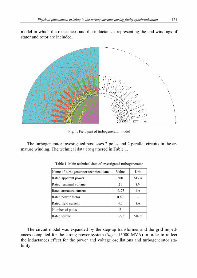
The turbogenerator investigated possesses 2 poles and 2 parallel circuits in the ar-mature winding. The technical data are gathered in Table 1.
Table 1. Main technical data of investigated turbogenerator
Name of turbogenerator technical data Value Unit
Rated apparent power 500 MVA
Rated terminal voltage 21 kV
Rated armature current 13.75 kA
Rated power factor 0.80 –
Rated field current 4.5 kA
Number of poles 2 –
Rated torque 1.273 MNm
The circuit model was expanded by the step-up transformer and the grid imped-ances computed for the strong power system (SkQ = 15000 MVA) in order to reflectthe inductances effect for the power and voltage oscillations and turbogenerator sta-bility.
A. GOZDOWIAK et al.152
3. COMPUTATION RESULTS
3.1. FAULTY SYNCHRONIZATIONWITH INVERSE PHASE SEQUENCE
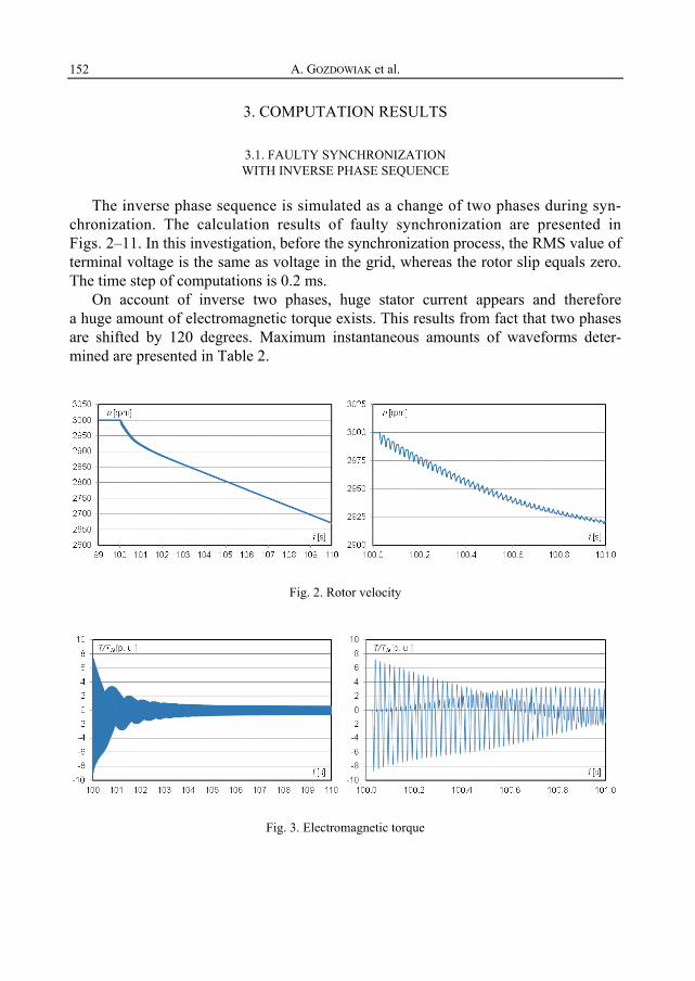
The inverse phase sequence is simulated as a change of two phases during syn-chronization. The calculation results of faulty synchronization are presented inFigs. 2–11. In this investigation, before the synchronization process, the RMS value ofterminal voltage is the same as voltage in the grid, whereas the rotor slip equals zero.The time step of computations is 0.2 ms.
On account of inverse two phases, huge stator current appears and thereforea huge amount of electromagnetic torque exists. This results from fact that two phasesare shifted by 120 degrees. Maximum instantaneous amounts of waveforms deter-mined are presented in Table 2.
Fig. 2. Rotor velocity
Fig. 3. Electromagnetic torque

Physical phenomena existing in the turbogenerator during faulty synchronization... 153
Fig. 4. Terminal voltage waveform in each phase
Fig. 5. Stator current waveform in each phase
Fig. 6. Negative sequence of stator current
Huge amount of negative sequence of stator current causes that huge currents withdouble grid frequency, 2fN, are induced in the rotor wedges, solid rotor shaft and infield winding. The waveforms of these currents are shown in Figs. 7–9. The most vulner-able construction element is rotor wedge number 7 localized near to rotor big edge, seeFig. 1. Current flows in each of the rotor wedges investigated are presented in Fig. 9.

A. GOZDOWIAK et al.154
Fig. 7. Field current waveform
Fig. 8. Current waveform in the rotor wedge no. 7
Fig. 9. Current waveforms in the rotor wedges
Additionally, the absorbed active power and reactive power from the power systemare determined by using measurement algorithms, as shown in Figs. 10 and 11, re-spectively.

Physical phenomena existing in the turbogenerator during faulty synchronization... 155
Fig. 10. Active power absorbed from the power system
Fig. 11. Reactive power absorbed from the power system
3.2. SIMULATION RESULTS
The turbogenerator is designed to sustain the instantaneous stator currents and theshaft torques resulting from the three phase short circuit at the terminals. In this place,the different cases under study are presented in order to show the highest threats ex-isting during faulty synchronization with inverse phase sequence. The calculationresults are summarized in Table 2 for all the cases investigated.
Computed maximum instantaneous amplitude of electromagnetic torque equals8.82TN during faulty synchronization with inverse phase sequence. Whereas in thecase of a sudden three phase short circuit at no-load at UN, the maximum amplitude ofelectromagnetic torque equals 3.65TN. This means that the torque that appeared duringfaulty synchronization is 2.4 times higher. Additionally, a sudden three phase shortcircuit during rated operation condition was considered. This case is unrealistic be-cause in the power plant the connection phases coming from the turbogenerator termi-nals which are connected to step-up transformer are isolated from each other. Even inthis case the maximum amplitude of electromagnetic torque is lower than in the caseof faulty synchronization being investigated and equals 8.31TN despite the fact that themaximum amplitude of the stator current is the highest. The description of physical

A. GOZDOWIAK et al.156
phenomena existing during sudden short circuit based on finite element method can befound in [9].
Table. 2. Instantaneous amplitudes of determined waveforms during the simulation
Cases under study TMAX[p.u.]
US MIN[p.u.]
IS MAX[p.u.]
I2 MAX[p.u.]
IF MAX[p.u.]
IW7 MAX[kA]
PMAX[p.u.]
1 Faulty synchronization with inversephase sequence at UN and slip = 0 8.82 0.23 10.10 4.46 2.62 152.84 0.23
2 Faulty synchronization with inversephase sequence at 1.05UN and slip = 0 9.32 0.21 9.88 3.17 2.69 154.93 1.18
3 Faulty synchronization with inversephase sequence at UN and n = 2996 rpm 9.05 0.20 10.71 5.04 2.66 158.15 0.22
4 Faulty synchronization with inversephase sequence at UN and n = 3004 rpm 8.81 0.23 10.42 4.27 2.62 154.51 0.49
5 Sudden three phase short circuit atno-load at UN
3.65 6.03 88.75
6 Sudden three phase short circuitat rated operation condition 8.31 11.82 129.18
The rule in [10] presents the following synchronizing limits: breaker closing angle,generator side voltage relative to system and frequency difference. The latter two aretaken into account during investigations. The computed results are included also inTable 2. The maximum voltage deviation is 5%, whereas this voltage cannot be lowerthan UN in order to avoid the reactive power being absorbed by the turbogenerator.Therefore, the maximum acceptable voltage used equals 1.05UN. An increase of ter-minal voltage causes an increase of maximum electromagnetic torque and a decreaseof maximum stator current amplitude.
Acceptable frequency difference is in the range from –0.067 to 0.067 Hz. It meansthat acceptable speed difference is 4 rpm. There is an increase of stator current am-plitudes for both lower and higher speed than synchronous speed. Whereas lowerspeed contributes to appearance of higher maximum electromagnetic torque.
The highest stator current amplitude and thereby the highest instantaneous negativesequence of stator current was recorded in the case of lower speed than synchronousspeed. Higher negative sequence of stator current has an impact of induced current in theconductive parts of the rotor. There is a huge risk of the retaining ring damage.
4. CONCLUSIONS
The simulation study of turbogenerator behavior in the power system by using fi-nite element method allows us to reflect the real physical phenomena existing insidethe turbogenerator.
Physical phenomena existing in the turbogenerator during faulty synchronization... 157
Faulty synchronization with inverse phase sequence causes an appearance ofhigher electromagnetic torque than in the case of a sudden short circuit and therebyhuge mechanical stresses which can lead to the rotor shaft damage. The most vulner-able construction element is rotor wedge number 7 localized near to the rotor big edge.This conclusion is proper for all the cases investigated. Huge inducted currents in theconductive parts of the rotor which appear on account of stator current negative se-quence can cause failure of the retaining ring.
The worst case is for 1.05UN (2nd investigated case, Table 2) from the point ofview of the mechanical stress. Whereas from the thermal point of view, the worst caseis when speed is below synchronous speed (3rd case, Table 2).
REFERENCES
[1] BILLINTON R., ABORESHAID S., FARIED S.O., FOTUHI-FIRUZABAS M., A Monte Carlo simulation ap-proach to the evaluation of maximum turbine-generator shaft torsional torques during faulty syn-chronization, IEEE Trans. Power Systems, 1999, Vol. 14, No. 4.
[2] ABORESHAID S., AL-DHALAAN S., Stochastic evaluation of turbine-generator shaft fatigue due tosystem faults and faulty synchronization, IEEE Power Engineering Society Winter Meeting, 2000,Vol. 1, 186–191.
[3] KRAUSE P.C., HOLLOPETER W.C., TRIEZENBERG D.M., RUSCHE P.A., Shaft torques during out-of-phasesynchronization, IEEE Trans. Power Apparatus and Systems, 1977, Vol. PAS-96, No. 4
[4] MITSCHE J.V., RUSCHE P.A., Shaft torsional stress due to asynchronous faulty synchronization,IEEE Transactions on Power Apparatus and Systems, 1980, Vol. PAS-99, No. 5.
[5] PASTERNACK B.M., PROVANZANA J.H., WAGANAAR L.B., Analysis of a generator step-up transformerfailure following faulty synchronization, IEEE Trans. Power Delivery, 1988, Vol. 3, No. 3.
[6] GOZDOWIAK A., KISIELEWSKI P., Identification and verification of the turbogenerator parametersdetermined from the field and field-circuit simulation, Scientific Papers of the Institute of ElectricalMachines, Drives and Measurements of Wrocław University of Technology, Studies and Research,2014, Vol. 34, 303–314, (in Polish).
[7] KISIELEWSKI P., ANTAL L., Field-circuit model of the turbogenerator, Scientific Papers of the Insti-tute of Electrical Machines, Drives and Measurements of Wrocław University of Technology,Studies and Research, 2006, Vol. 26, 53–60, (in Polish).
[8] KISIELEWSKI P., ANTAL L., Verification of calculated turbogenerator characteristics, Electrical Ma-chines – Transaction Journal, 2007, No. 76, 167–170, (in Polish).
[9] KISIELEWSKI P., ANTAL L., Physical phenomena in turbogenerator during short-circuit, ScientificPapers of the Institute of Electrical Machines, Drives and Measurements of Wrocław University ofTechnology, Studies and Research, 2006, Vol. 26, 61–68, (in Polish).
[10] IEEE Std C50.13, IEEE Standard for Cylindrical-Rotor 50 Hz and 60 Hz Synchronous GeneratorsRated 10 MVA and Above.
Related Documents