Physical layer structure of next generation mobile WiMAX technology HanGyu Cho a,⇑ , Taeyoung Kim b , Yu-Tao Hsieh c , Jong-Kae Fwu d a LG Electronics, 533 LG R&D Complex, Hogye 1Dong, Dongan Gu, Kyunggi Do, Anyang Shi, Gyeonggi-do 431-831, South Korea b Samsung Electronics, 416 Maetan-3dong, Yeongton-gu, Suwon-city, Gyeonggi-do 443-742, South Korea c ITRI 195, Sec. 4, Chung Hsing Rd., Chudong, Hsinchu 310, Taiwan, ROC d Intel Corporation, RNB-5-123, 2200 Mission College Blvd, Santa Clara, CA 95054, United States article info Article history: Received 13 May 2010 Received in revised form 13 January 2011 Accepted 10 March 2011 Available online 14 June 2011 Keywords: 4G WiMAX IEEE 802.16m Physical layer IMT-Advanced OFDMA abstract To meet the tremendous demand and growth for mobile Internet and wireless multimedia applications, various advanced mobile technologies are under extensive investigation in recent years. The IEEE 802.16 Working Group Task Group m (TGm) has been developing a 4G mobile WiMAX system since early 2007. This paper provides a detailed overview of the prominent features and structure of the physical layer of IEEE 802.16m and also pro- vides simulation results of spectral efficiency performance. Ó 2011 Elsevier B.V. All rights reserved. 1. Introduction The International Telecommunication Union – Radio Communication sector (ITU-R) has defined the technical requirements of the radio interface(s) for International Mo- bile Telecommunications-Advanced (IMT-Advanced) to meet the growing demand on mobile services beyond IMT-2000 [1]. IEEE 802.16m Working Group Task Group m (TGm) has been developing a next-generation mobile WiMAX system since early 2007 [2]. The next-generation mobile WiMAX system, as a new amendment of the IEEE 802.16 standard (i.e., IEEE 802.16m), will provide enhancements including higher throughput/mobility, higher user capacity, and lower latency while maintaining full backward compatibility with the existing mobile WiMAX systems (IEEE 802.16e) [3]. Currently, 16m specifications are tracking towards the sponsor ballot completion by the end of 2010. Physical layer structure refers to the design of multi- plexing user and system data with control signaling to en- sure proper use of radio resources by users. A frame structure first partitions the time domain resources into frames within which the time–frequency–space resources are further organized according to a more refined resource structure. OFDMA (Orthogonal Frequency Division Multiple Access) and MIMO (Multiple Input and Multiple Output), as two keystone 4G physical layer technologies, allow the minimal resource unit to be one subcarrier for a duration of one OFDM symbol in each spatial layer. Phys- ical layer design specifies how to group, map, and allocate time–frequency–space resources as either reference sig- nals or to form various physical channels. Reference signals and control/physical channels are defined to fulfill neces- sary system functionalities, and thus collectively specify proper system operations (e.g. cell synchronization, system configuration information decoding, and Downlink (DL) and Uplink (UL) data allocation decoding based on pilot signals). 1389-1286/$ - see front matter Ó 2011 Elsevier B.V. All rights reserved. doi:10.1016/j.comnet.2011.03.022 ⇑ Corresponding author. Tel.: +82 31 450 1857. E-mail addresses: [email protected] (H. Cho), [email protected] (T. Kim), [email protected] (Y.-T. Hsieh), [email protected] (J.-K. Fwu). Computer Networks 55 (2011) 3648–3658 Contents lists available at ScienceDirect Computer Networks journal homepage: www.elsevier.com/locate/comnet

Welcome message from author
This document is posted to help you gain knowledge. Please leave a comment to let me know what you think about it! Share it to your friends and learn new things together.
Transcript
Computer Networks 55 (2011) 3648–3658
Contents lists available at ScienceDirect
Computer Networks
journal homepage: www.elsevier .com/locate /comnet
Physical layer structure of next generation mobile WiMAX technology
HanGyu Cho a,⇑, Taeyoung Kim b, Yu-Tao Hsieh c, Jong-Kae Fwu d
a LG Electronics, 533 LG R&D Complex, Hogye 1Dong, Dongan Gu, Kyunggi Do, Anyang Shi, Gyeonggi-do 431-831, South Koreab Samsung Electronics, 416 Maetan-3dong, Yeongton-gu, Suwon-city, Gyeonggi-do 443-742, South Koreac ITRI 195, Sec. 4, Chung Hsing Rd., Chudong, Hsinchu 310, Taiwan, ROCd Intel Corporation, RNB-5-123, 2200 Mission College Blvd, Santa Clara, CA 95054, United States
a r t i c l e i n f o a b s t r a c t
Article history:Received 13 May 2010Received in revised form 13 January 2011Accepted 10 March 2011Available online 14 June 2011
Keywords:4GWiMAXIEEE 802.16mPhysical layerIMT-AdvancedOFDMA
1389-1286/$ - see front matter � 2011 Elsevier B.Vdoi:10.1016/j.comnet.2011.03.022
⇑ Corresponding author. Tel.: +82 31 450 1857.E-mail addresses: [email protected] (H. Cho), ty3
(T. Kim), [email protected] (Y.-T. Hsieh), jon(J.-K. Fwu).
To meet the tremendous demand and growth for mobile Internet and wireless multimediaapplications, various advanced mobile technologies are under extensive investigation inrecent years. The IEEE 802.16 Working Group Task Group m (TGm) has been developinga 4G mobile WiMAX system since early 2007. This paper provides a detailed overview ofthe prominent features and structure of the physical layer of IEEE 802.16m and also pro-vides simulation results of spectral efficiency performance.
� 2011 Elsevier B.V. All rights reserved.
1. Introduction
The International Telecommunication Union – RadioCommunication sector (ITU-R) has defined the technicalrequirements of the radio interface(s) for International Mo-bile Telecommunications-Advanced (IMT-Advanced) tomeet the growing demand on mobile services beyondIMT-2000 [1].
IEEE 802.16m Working Group Task Group m (TGm) hasbeen developing a next-generation mobile WiMAX systemsince early 2007 [2]. The next-generation mobile WiMAXsystem, as a new amendment of the IEEE 802.16 standard(i.e., IEEE 802.16m), will provide enhancements includinghigher throughput/mobility, higher user capacity, and lowerlatency while maintaining full backward compatibility withthe existing mobile WiMAX systems (IEEE 802.16e) [3].
. All rights reserved.
[email protected]@intel.com
Currently, 16m specifications are tracking towards thesponsor ballot completion by the end of 2010.
Physical layer structure refers to the design of multi-plexing user and system data with control signaling to en-sure proper use of radio resources by users. A framestructure first partitions the time domain resources intoframes within which the time–frequency–space resourcesare further organized according to a more refined resourcestructure. OFDMA (Orthogonal Frequency DivisionMultiple Access) and MIMO (Multiple Input and MultipleOutput), as two keystone 4G physical layer technologies,allow the minimal resource unit to be one subcarrier fora duration of one OFDM symbol in each spatial layer. Phys-ical layer design specifies how to group, map, and allocatetime–frequency–space resources as either reference sig-nals or to form various physical channels. Reference signalsand control/physical channels are defined to fulfill neces-sary system functionalities, and thus collectively specifyproper system operations (e.g. cell synchronization, systemconfiguration information decoding, and Downlink (DL)and Uplink (UL) data allocation decoding based on pilotsignals).
H. Cho et al. / Computer Networks 55 (2011) 3648–3658 3649
IEEE 802.16m employs OFDMA as the multiple accessscheme in both downlink and uplink, same as its precedentIEEE 802.16e. IEEE 802.16m supports time division duplex-ing (TDD) and frequency division duplexing (FDD) duplexmodes, including half-duplex FDD (H-FDD) MS operationin the FDD networks. The physical layer designs are com-mon for both duplex schemes, including frame structure,symbol structure, etc.
IEEE 802.16m supports various MIMO, beamformingoperation and other advanced antenna techniques, includ-ing single-user and multi-user MIMO techniques. The min-imum antenna configuration for 16m is (1) two transmitand two receive antennas for base stations (BS) and (2)one transmit and two received antennas for mobile sta-tions (MS). Up to 8 DL transmit antennas can be supportedin 16m. One of the main challenges in designing the802.16m physical layer is to provide significant perfor-mance improvement over the existing IEEE 802.16e prod-ucts while maintaining full backward compatibility withthe existing mobile WiMAX system. The goal is to designa mobile WiMAX system which (1) meets or exceedsIMT-Advance requirement (2) preserves the carrier’s cur-rent investment and (3) serve the needs of various futuremobile wireless applications.
This paper provides an overview of the physical layerstructure of the IEEE 802.16m radio interface technologies,focusing on aspects such as frame structure, resource unit,reference signals, and resource mapping. Design details ofDL/UL subchannelization and permutation efficiency aredescribed and simulation results are provided to showthe design performance trade-off, i.e., spectral efficiencyand average signal to interference and noise ratio (SINR)distribution after permutation.
2. Physical layer of IEEE 802.16m
2.1. Frame structure
IEEE 802.16m supports full backward compatibility andinteroperability to ensure a smooth migration from legacy
SU0
F0
SU1
Superframe : 20 ms
F1 F2
Frame : 5 ms
SF0 SF1 SF2 SF3 SF4 SF5 SF6 SF
S0
S1
S2
S3
S4
S5
Subframe
OFDM Symbol
Fig. 1. Basic frame structure with a CP length of 1/8
16e system to intermediated mixed 16e/16m network andthen to new Greenfield 16m systems without significantimpact on the performance of the legacy systems. Thesuperframe is a group of consecutive, equally-sized radioframes, where the beginning is marked with a superframeheader (SFH) which carries essential system-configurationinformation. The radio frames are further divided into anumber of subframes where each subframe comprises aninteger number of OFDMA symbols. 802.16m frame struc-ture is designed, based on the following key features:
� Commonality 802.16m frame structure is designedsuch that commonality between TDD and FDD modeis maximized for implementation smartness. That is,except that one symbol is used for TTG in TDD, framestructures between TDD and FDD are almost common.� Hierarchical frame structure 802.16m is based on a
hierarchical frame structure consisting of superframe,frame, and subframe. By broadcasting system informa-tion through DL dedicated control CH per superframe,control overhead reduction is achieved. Subframe-based HARQ operation provides latency reduction.� Backward compatibility 802.16m provides continuing
support and interoperability for 16e equipment, includ-ing MSs and BSs. Specifically, the features, functions andprotocols enabled in 802.16m support the features,functions and protocols employed by 16e equipment.For this purpose, 802.16m supports both 16m-onlymode (called green-field) and 16m/legacy-mixed (i.e.,16m/16e mixed) mode. For mixed mode, flexible ratiobetween 16m MSs and legacy 16e MSs is supported,which is very useful for smooth migration frommixed-mode to 16m-only mode.� Flexibility 802.16m frame structure supports various
cyclic prefix (CP) lengths and channel bandwidths tosupport flexible deployment and usage cases. Thereare three CP lengths supported: 1/8Tb, 1/16Tb, and 1/4Tb, where Tb is the useful symbol time. Among them,1/16Tb and 1/4Tb are applicable only to 16m-only modewhile 1/8Tb is applicable to both 16m-only mode andmixed-mode. The nominal channel bandwidths of
Superframe Header
SU2 SU3
F3
7
Tb for 5, 10 and 20 MHz channel bandwidth.
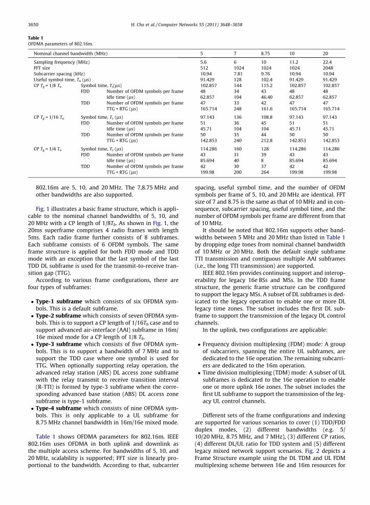
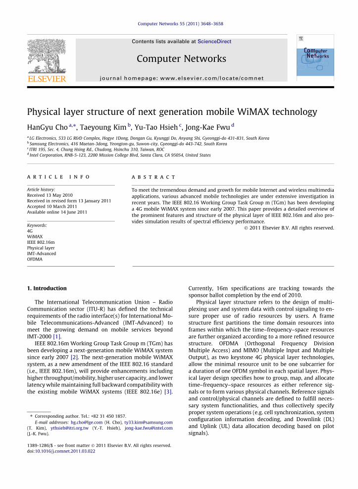
Table 1OFDMA parameters of 802.16m.
Nominal channel bandwidth (MHz) 5 7 8.75 10 20
Sampling frequency (MHz) 5.6 6 10 11.2 22.4FFT size 512 1024 1024 1024 2048Subcarrier spacing (kHz) 10.94 7.81 9.76 10.94 10.94Useful symbol time, Tu (ls) 91.429 128 102.4 91.429 91.429CP Tg = 1/8 Tu Symbol time, Ts(ls) 102.857 144 115.2 102.857 102.857
FDD Number of OFDM symbols per frame 48 34 43 48 48Idle time (ls) 62.857 104 46.40 62.857 62.857
TDD Number of OFDM symbols per frame 47 33 42 47 47TTG + RTG (ls) 165.714 248 161.6 165.714 165.714
CP Tg = 1/16 Tu Symbol time, Ts (ls) 97.143 136 108.8 97.143 97.143FDD Number of OFDM symbols per frame 51 36 45 51 51
Idle time (ls) 45.71 104 104 45.71 45.71TDD Number of OFDM symbols per frame 50 35 44 50 50
TTG + RTG (ls) 142.853 240 212.8 142.853 142.853
CP Tg = 1/4 Tu Symbol time, Ts (ls) 114.286 160 128 114.286 114.286FDD Number of OFDM symbols per frame 43 31 39 43 43
Idle time (ls) 85.694 40 8 85.694 85.694TDD Number of OFDM symbols per frame 42 30 37 42 42
TTG + RTG (ls) 199.98 200 264 199.98 199.98
3650 H. Cho et al. / Computer Networks 55 (2011) 3648–3658
802.16m are 5, 10, and 20 MHz. The 7,8.75 MHz andother bandwidths are also supported.
Fig. 1 illustrates a basic frame structure, which is appli-cable to the nominal channel bandwidths of 5, 10, and20 MHz with a CP length of 1/8Tb. As shown in Fig. 1, the20ms superframe comprises 4 radio frames with length5ms. Each radio frame further consists of 8 subframes.Each subframe consists of 6 OFDM symbols. The sameframe structure is applied for both FDD mode and TDDmode with an exception that the last symbol of the lastTDD DL subframe is used for the transmit-to-receive tran-sition gap (TTG).
According to various frame configurations, there arefour types of subframes:
� Type-1 subframe which consists of six OFDMA sym-bols. This is a default subframe.� Type-2 subframe which consists of seven OFDMA sym-
bols. This is to support a CP length of 1/16Tb case and tosupport advanced air-interface (AAI) subframe in 16m/16e mixed mode for a CP length of 1/8 Tb.� Type-3 subframe which consists of five OFDMA sym-
bols. This is to support a bandwidth of 7 MHz and tosupport the TDD case where one symbol is used forTTG. When optionally supporting relay operation, theadvanced relay station (ARS) DL access zone subframewith the relay transmit to receive transition interval(R-TTI) is formed by type-3 subframe when the corre-sponding advanced base station (ABS) DL access zonesubframe is type-1 subframe.� Type-4 subframe which consists of nine OFDMA sym-
bols. This is only applicable to a UL subframe for8.75 MHz channel bandwidth in 16m/16e mixed mode.
Table 1 shows OFDMA parameters for 802.16m. IEEE802.16m uses OFDMA in both uplink and downlink asthe multiple access scheme. For bandwidths of 5, 10, and20 MHz, scalability is supported; FFT size is linearly pro-portional to the bandwidth. According to that, subcarrier
spacing, useful symbol time, and the number of OFDMsymbols per frame of 5, 10, and 20 MHz are identical. FFTsize of 7 and 8.75 is the same as that of 10 MHz and in con-sequence, subcarrier spacing, useful symbol time, and thenumber of OFDM symbols per frame are different from thatof 10 MHz.
It should be noted that 802.16m supports other band-widths between 5 MHz and 20 MHz than listed in Table 1by dropping edge tones from nominal channel bandwidthof 10 MHz or 20 MHz. Both the default single subframeTTI transmission and contiguous multiple AAI subframes(i.e., the long TTI transmission) are supported.
IEEE 802.16m provides continuing support and interop-erability for legacy 16e BSs and MSs. In the TDD framestructure, the generic frame structure can be configuredto support the legacy MSs. A subset of DL subframes is ded-icated to the legacy operation to enable one or more DLlegacy time zones. The subset includes the first DL sub-frame to support the transmission of the legacy DL controlchannels.
In the uplink, two configurations are applicable:
� Frequency division multiplexing (FDM) mode: A groupof subcarriers, spanning the entire UL subframes, arededicated to the 16e operation. The remaining subcarri-ers are dedicated to the 16m operation.� Time division multiplexing (TDM) mode: A subset of UL
subframes is dedicated to the 16e operation to enableone or more uplink 16e zones. The subset includes thefirst UL subframe to support the transmission of the leg-acy UL control channels.
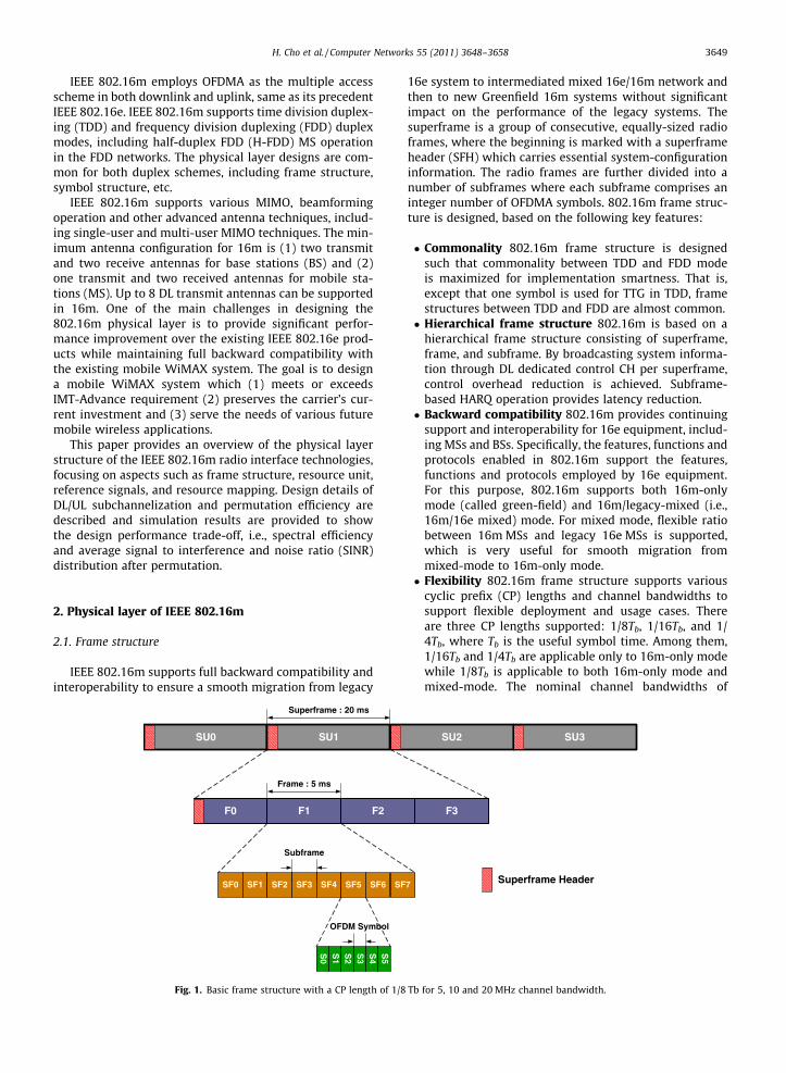
Different sets of the frame configurations and indexingare supported for various scenarios to cover (1) TDD/FDDduplex modes, (2) different bandwidths (e.g. 5/10/20 MHz, 8.75 MHz, and 7 MHz), (3) different CP ratios,(4) different DL/UL ratio for TDD system and (5) differentlegacy mixed network support scenarios. Fig. 2 depicts aFrame Structure example using the DL TDM and UL FDMmultiplexing scheme between 16e and 16m resources for
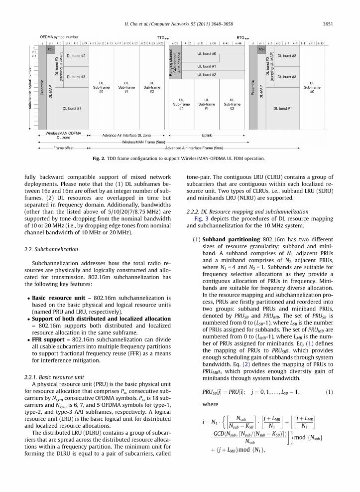
Fig. 2. TDD frame configuration to support WirelessMAN-OFDMA UL FDM operation.
H. Cho et al. / Computer Networks 55 (2011) 3648–3658 3651
fully backward compatible support of mixed networkdeployments. Please note that the (1) DL subframes be-tween 16e and 16m are offset by an integer number of sub-frames, (2) UL resources are overlapped in time butseparated in frequency domain. Additionally, bandwidths(other than the listed above of 5/10/20/7/8.75 MHz) aresupported by tone-dropping from the nominal bandwidthof 10 or 20 MHz (i.e., by dropping edge tones from nominalchannel bandwidth of 10 MHz or 20 MHz).
2.2. Subchannelization
Subchannelization addresses how the total radio re-sources are physically and logically constructed and allo-cated for transmission. 802.16m subchannelization hasthe following key features:
� Basic resource unit – 802.16m subchannelization isbased on the basic physical and logical resource units(named PRU and LRU, respectively).� Support of both distributed and localized allocation
– 802.16m supports both distributed and localizedresource allocation in the same subframe.� FFR support – 802.16m subchannelization can divide
all usable subcarriers into multiple frequency partitionsto support fractional frequency reuse (FFR) as a meansfor interference mitigation.
2.2.1. Basic resource unitA physical resource unit (PRU) is the basic physical unit
for resource allocation that comprises Psc consecutive sub-carriers by Nsym consecutive OFDMA symbols. Psc is 18 sub-carriers and Nsym is 6, 7, and 5 OFDMA symbols for type-1,type-2, and type-3 AAI subframes, respectively. A logicalresource unit (LRU) is the basic logical unit for distributedand localized resource allocations.
The distributed LRU (DLRU) contains a group of subcar-riers that are spread across the distributed resource alloca-tions within a frequency partition. The minimum unit forforming the DLRU is equal to a pair of subcarriers, called
tone-pair. The contiguous LRU (CLRU) contains a group ofsubcarriers that are contiguous within each localized re-source unit. Two types of CLRUs, i.e., subband LRU (SLRU)and minibands LRU (NLRU) are supported.
2.2.2. DL Resource mapping and subchannelizationFig. 3 depicts the procedures of DL resource mapping
and subchannelization for the 10 MHz system.
(1) Subband partitioning 802.16m has two differentsizes of resource granularity: subband and mini-band. A subband comprises of N1 adjacent PRUsand a miniband comprises of N2 adjacent PRUs,where N1 = 4 and N2 = 1. Subbands are suitable forfrequency selective allocations as they provide acontiguous allocation of PRUs in frequency. Mini-bands are suitable for frequency diverse allocation.In the resource mapping and subchannelization pro-cess, PRUs are firstly partitioned and reordered intotwo groups: subband PRUs and miniband PRUs,denoted by PRUSB and PRUMB. The set of PRUSB isnumbered from 0 to (LSB-1), where LSB is the numberof PRUs assigned for subbands. The set of PRUMB arenumbered from 0 to (LMB-1), where LMB is the num-ber of PRUs assigned for minibands. Eq. (1) definesthe mapping of PRUs to PRUSBs, which providesenough scheduling gain of subbands through systembandwidth. Eq. (2) defines the mapping of PRUs toPRUMBs, which provides enough diversity gain ofminibands through system bandwidth.
PRUSB½j� ¼ PRU½i�; j ¼ 0;1; . . . ; LSB � 1; ð1Þ
where
i ¼ N1 �Nsub
Nsub � KSB
� �� jþ LMB
N1
� �þ jþ LMB
N1
� ���
� GCDðNsub; Nsub=ðNsub � KSBÞd eÞNsub
��mod fNsubg
þ fjþ LMBgmod fN1g;
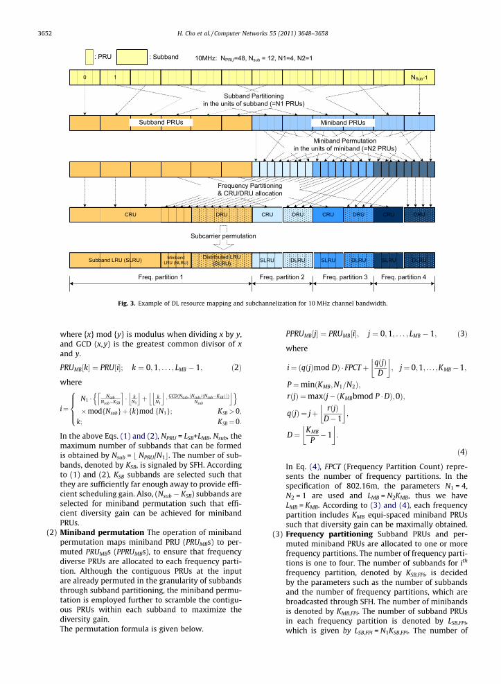
Fig. 3. Example of DL resource mapping and subchannelization for 10 MHz channel bandwidth.
3652 H. Cho et al. / Computer Networks 55 (2011) 3648–3658
where {x} mod {y} is modulus when dividing x by y,and GCD (x,y) is the greatest common divisor of xand y.
PRUMB½k� ¼ PRU½i�; k ¼ 0;1; . . . ; LMB � 1; ð2Þ
where
i¼N1 � Nsub
Nsub�KSB
l m� k
N1
j kþ k
N1
j k� GCDðNsub ; Nsub=ðNsub�KSBÞd eÞ
Nsub
j kn o�modfNsubgþfkgmod fN1g; KSB > 0;
k; KSB ¼ 0:
8>><>>:
In the above Eqs. (1) and (2), NPRU = LSB+LMB. Nsub, themaximum number of subbands that can be formedis obtained by Nsub = b NPRU/N1c. The number of sub-bands, denoted by KSB, is signaled by SFH. Accordingto (1) and (2), KSB subbands are selected such thatthey are sufficiently far enough away to provide effi-cient scheduling gain. Also, (Nsub � KSB) subbands areselected for miniband permutation such that effi-cient diversity gain can be achieved for minibandPRUs.
(2) Miniband permutation The operation of minibandpermutation maps miniband PRU (PRUMBs) to per-muted PRUMBs (PPRUMBs), to ensure that frequencydiverse PRUs are allocated to each frequency parti-tion. Although the contiguous PRUs at the inputare already permuted in the granularity of subbandsthrough subband partitioning, the miniband permu-tation is employed further to scramble the contigu-ous PRUs within each subband to maximize thediversity gain.The permutation formula is given below.
PPRUMB½j� ¼ PRUMB½i�; j ¼ 0;1; . . . ; LMB � 1; ð3Þ
where
i¼ ðqðjÞmod DÞ � FPCT þ qðjÞD
� �; j¼ 0;1; . . . ;KMB�1;
P ¼minðKMB;N1=N2Þ;rðjÞ ¼maxðj�ðKMBbmod P �DÞ;0Þ;
qðjÞ ¼ jþ rðjÞD�1
� �;
D¼ KMB
P�1
� �:
ð4Þ
In Eq. (4), FPCT (Frequency Partition Count) repre-sents the number of frequency partitions. In thespecification of 802.16m, the parameters N1 = 4,N2 = 1 are used and LMB = N2KMB, thus we haveLMB = KMB. According to (3) and (4), each frequencypartition includes KMB equi-spaced miniband PRUssuch that diversity gain can be maximally obtained.
(3) Frequency partitioning Subband PRUs and per-muted miniband PRUs are allocated to one or morefrequency partitions. The number of frequency parti-tions is one to four. The number of subbands for ith
frequency partition, denoted by KSB,FPi, is decidedby the parameters such as the number of subbandsand the number of frequency partitions, which arebroadcasted through SFH. The number of minibandsis denoted by KMB,FPi. The number of subband PRUsin each frequency partition is denoted by LSB,FPi,which is given by LSB,FPi = N1KSB,FPi. The number of
H. Cho et al. / Computer Networks 55 (2011) 3648–3658 3653
miniband PRUs in each frequency partition isdenoted by LMB,FPi, which is given by LMB,FPi =N2KMB,FPi.The mapping of subband PRUs and miniband PRUsto the frequency partition i is given by Eq. (5):
PRUFPiðjÞ ¼PRUSBðk1Þ for 0 6 j < LSB;FPi;
PPRUMBðk2Þ for LSB;FPi 6 j < ðLSB;FPi þ LMB;FPiÞ;
�
ð5Þ
where k1 ¼Pi�1
m¼0LSB;FPm þ j and k2 ¼Pi�1
m¼0LMB;FPmþj� LSB;FPi.According to (5), LSB,FPi subband PRUs are allocatedto frequency partition i in order, and followed byLMB,FPi miniband PRUs.
(4) CRU/DRU allocation PRUs in each frequency parti-tion are further partitioned into contiguous resourceunits (CRU) and distributed resource units (DRU),which are mapped later to contiguous LRU (CLRU)and distributed LRU (DLRU), respectively. The parti-tion between CRUs and DRUs is done on a sectorspecific basis. Let LSB�CRU,FPi and LMB�CRU,FPi denotethe number of allocated subband CRUs and mini-band CRUs for FPi(i P 0). The total number of CRUsin frequency partition FPi, for 0 6 i < FPCT, is denotedby LCRU,FPi, where
LCRU;FPi ¼ LSB�CRU;FPi þ LMB�CRU;FPi: ð6Þ
The number of DRUs in each frequency partition isdenoted by LDRU,FPi, where
LDRU;FPi ¼ FPSi � LCRU;FPi ð7Þ
and FPSi is the number of PRUs allocated to FPi. Thatis, frequency partition i includes LCRU,FPi CRUs, whichconsists of LSB�CRU,FPi subband CRUs and LMB�CRU,FPi
miniband CRUs, and LDRU,FPi DRUs.
(5) Subcarrier permutation After CRU/DRU allocation,the CRUs are directly mapped into contiguous LRUs,including SLRUs and NLRUs. The downlink DRUs aremapped to DLRUs by subcarrier permutation. Thesubcarrier permutation spreads the subcarriers ofthe DRU across the whole distributed resource allo-cation within the frequency partition to maximizefrequency diversity gain. A sector-specific seed valueis used for subcarrier permutation for interferenceaveraging between different sectors. The granularityof the subcarrier permutation is a pair of adjacentsubcarriers in the frequency domain to support aspace frequency block code (SFBC) MIMO scheme.The subcarrier permutation rule is defined for thelth OFDMA symbol in the subframe, as follows.
� After allocating pilots within each DRU, the datasubcarriers of the DRU aare renumbered exceptfor the allocated pilot subcarriers. Group theserenumbered subcarriers into subcarrier pairs.The uth renumbered subcarrier pairs in the lthOFDMA symbol within the ith frequency parti-tion is denoted by RSPFPi,l[u].
� The subcarrier permutation formula to mapRSPFPi,l into the sth DLRU is given by
SPFPiLRU;s;l½m� ¼ RSPFPi;l½k�; ð8Þ
where SPFPiLRU;s;l½m� is the mth subcarrier pair in the lth OFD-
MA symbol in the sth DLRU within the ith frequency parti-tion and m is the subcarrier index, 0 to LSP,l-1 and k isdefined as
k ¼ LDRU;FPi � ½ðmþ 13 � ðsþ lÞÞmodLSP;l�þ gðseqðÞ; s;m; lÞ; ð9Þ
where LDRU,FPi and LSP,l stands for the number of DRU withinthe ith frequency partition and the number of subcarrierpairs in the lth OFDMA symbol, respectively. seq() is thepermutation sequence of length LDRU,FPi [4]. g(seq(),s,n, t)is defined as
gðseqðÞ; s;m; lÞ ¼ fseq½ðf ðm; s; lÞ þ sþ lÞmod LDRU;FPi�þ DL PermBasegmod LDRU;FPi; ð10Þ
where f(m,s, l) = (m + 13�(s + l)) mod LSP,l and DL_PermBaseis set to IDcell sent through preamble.
According to (8)–(10), one subcarrier pair is permutedto another subcarrier pair within DRUs per symbol at eachfrequency partition such that subcarriers are distributedenough to provide diversity gain and randomization forinterference mitigation between cells.
Fig. 3 illustrates an example of DL resource mappingand subchannelization for 10 MHz channel bandwidth.The arrow therein means a mapping of resource in eachsubchannelization step.
2.2.3. UL Resource mapping and subchannelizationUL resource mapping is the same as downlink resource
mapping, except replacing DL subcarrier permutation withUL tile permutation. Each DRUs of an UL frequency parti-tion is divided into 3 tiles of 6 adjacent subcarriers overNsym symbols. The tiles within a frequency partition arecollectively tile-permuted to increase frequency-diversityacross the allocated resources. That is, physical tiles ofDRUs are mapped to logical tiles of UL DLRUs by tilepermutation.
(1) Tile permutation: Each of the DRUs of an UL fre-quency partition is divided into 3 tiles of 6 adjacentsubcarriers over Nsym symbols. The tiles within a fre-quency partition are collectively tile-permuted toobtain frequency-diversity across the allocatedresources. The tile permutation that allocates physi-cal tiles of DRUs to logical tiles of subchannels is per-formed in the following manner.
Tileðs;n; tÞ ¼ LDRU;FPi � nþ gðseqðÞ; s;n; tÞ; ð11Þ
where Tile(s,n, t) is the tile index of the nth tile in the sthDLRU of the ith subframe. LDRU,FPi means the number ofDRU within the ith frequency partition and n is the tile in-dex, 0–2, in a DLRU. t is the subframe index with respect tothe frame. s is the DLRU index, 0 to LDRU,FPi-1. seq() is thepermutation sequence of length LDRU,FPi[4]. g(seq(),s,n, t) isdefined as
3654 H. Cho et al. / Computer Networks 55 (2011) 3648–3658
gðseqðÞ; s;n; tÞ ¼ fseq½ðnþ 107 � sþ 1213 � tÞmod LDRU;FPi�þ UL PermBasegmodLDRU;FPi; ð12Þ
where UL_PermBase is set to IDcell sent through preamble.Similarly with DL case, according to (11) and (12), a tile
is permuted to another tile within DRUs at each frequencypartition such that each UL distributed allocation includestiles distributed enough to provide diversity gain and ran-domization for interference mitigation between cells.
3. Reference signals
There are three types of reference signals: pilot subcar-riers, MIMO midamble and UL sounding channel.
The transmission of pilot subcarriers is required forchannel estimation, channel quality measurements, andfrequency offset estimation, etc. The pilot patterns in802.16m have the following features.
� Low pilot overhead.� A unified pattern for common and dedicated pilots.� Equal pilot density for each transmission antenna.� Equal pilot density regardless of the number of allo-
cated PRUs for a user.
1
2
4
2 3
3
4 1
6 symb
18 c
ontig
uous
sub
carri
ers
(b) 4 Tx st(a) 1 and 2 Tx streams
12
12
12
12
12
12
6 symbols
18co
ntig
uous
sub
carri
ers
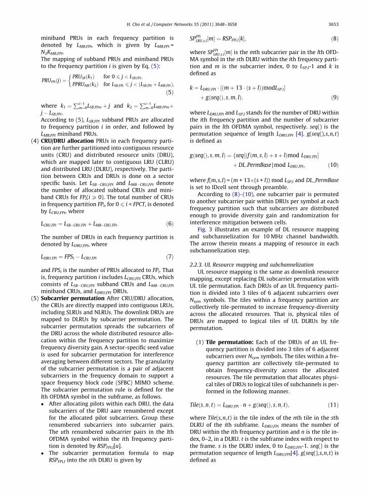
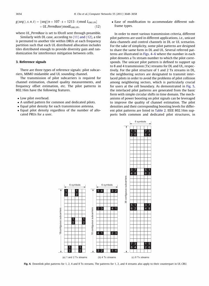
Fig. 4. Downlink pilot patterns for 1, 2, 4 and 8 Tx streams. The patterns
� Ease of modification to accommodate different sub-frame types.
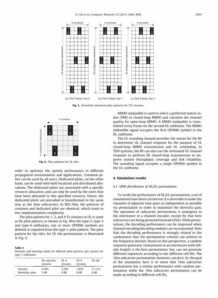
In order to meet various transmission criteria, differentpilot patterns are used in different applications, i.e., unicastdata channels and control channels in DL or UL scenarios.For the sake of simplicity, some pilot patterns are designedto share the same form in DL and UL. Several referred pat-terns are illustrated in Figs. 4–6 where the number in eachpilot denotes a Tx stream number to which the pilot corre-sponds. The unicast pilot pattern is defined to support upto 8 and 4 transmission (Tx) streams for DL and UL, respec-tively. For the pilot structure of 1 and 2 Tx streams in DL,the neighboring sectors are designated to transmit inter-laced pilots in order to avoid the problems of pilot collisionamong neighboring sectors, which is particularly crucialfor users at the cell boundary. As demonstrated in Fig. 5,the interlaced pilot patterns are generated from the basicform with simple circular shifts in time domain. The mech-anisms of power boosting on pilot signals can be leveragedto improve the quality of channel estimation. The pilotdensities and their corresponding boosting levels for differ-ent pilot patterns are listed in Table 2. IEEE 802.16m sup-ports both common and dedicated pilot structures, in
1 52 6
6 symbols36
con
tiguo
us s
ubca
rrier
s
7 38 4
3 74 8
5 16 2
1 75 36 42 8
7 38 4
1 52 6
3
4
2
14
1
2 3
ols
(c) 8 Tx streamsreams
for 1, 2, and 4 streams also apply to their counterpart in UL CRU.
12
12
12
12
12
12
6 symbols
18 c
ontig
uous
sub
carri
ers
12
12
12
12
12
12
6 symbols
18 c
ontig
uous
sub
carri
ers
12
12
12
12
12
12
6 symbols
18 c
ontig
uous
sub
carri
ers
(a) Pilot Pattern Set 0 (b) Pilot Pattern Set 1 (c) Pilot Pattern Set 2
Fig. 5. Downlink interlaced pilot patterns for 2Tx streams.
Fig. 6. Pilot patterns for UL tiles.
H. Cho et al. / Computer Networks 55 (2011) 3648–3658 3655
order to optimize the system performance in differentpropagation environments and applications,. Common pi-lots can be used by all users. Dedicated pilots, on the otherhand, can be used with both localized and distributed allo-cations. The dedicated pilots are associated with a specificresource allocation, and can only be used by the users thathave been allocated to this specified resource. Hence, thededicated pilots are precoded or beamformed in the sameway as the data subcarriers. In 802.16m, the patterns ofcommon and dedicated pilot are identical, which leads tolow implementation complexity.
The pilot pattern for 1, 2, and 4 Tx streams in UL is sameas DL pilot pattern, as shown in Fig. 4For the type-2, type-3and type-4 subframes, one or more OFDMA symbols aredeleted or repeated from the type-1 pilot pattern. The pilotpattern for the tiles, for UL tile permutation, is illustratedin Fig. 6.
Table 2Densities and boosting values for different pilot patterns (per stream) fortype-1 subframes.
DL one/twostreams
DL 4streams
DL 8streams
UL tile
Density 5.56% 3.70% 1.85% 11.11%Boosting value 2 dB 0 dB 0 dB 0 dB
MIMO midamble is used to select a preferred matrix in-dex (PMI) in closed-loop MIMO and calculate the channelquality for open-loop MIMO. A MIMO midamble is trans-mitted every frame on the second DL subframe. The MIMOmidamble signal occupies the first OFDMA symbol in theDL subframe.
The UL sounding channel provides the means for the BSto determine UL channel response for the purpose of ULclosed-loop MIMO transmission and UL scheduling. InTDD systems, the BS can also use the estimated UL channelresponse to perform DL closed-loop transmission to im-prove system throughput, coverage and link reliability.The sounding signal occupies a single OFDMA symbol inthe UL subframe.
4. Simulation results
4.1. SINR distribution of DL/UL permutation
To verify the performance of DL/UL permutation, a set ofsimulations have been carried out. It is desirable to make thechannels of adjacent tone-pairs as independent as possiblevia permutation in order to maximize the diversity gain.The operation of subcarrier permutation is analogous tothe interleaver in a channel encoder, except for that heresubcarriers are being permuted instead of bits. With permu-tations, the decoding performance can be improved whenchannel encoding/decoding modules are incorporated. Notethat the decoding performance is strongly related to therandomness that the permutation scheme can achieve inthe frequency domain. Based on this perspective, a randomsequence generator (tantamount to an interleaver with infi-nite length) is the best permutation, but, can not generatedifferent sequences according to the different cell IDs. The16m subcarrier permutation, however, can do it. So, the goalof the simulation here is to show that 16m subcarrierpermutation has a similar performance with random per-mutation while the 16m subcarrier permutation can bemade according to different cell IDs.
3656 H. Cho et al. / Computer Networks 55 (2011) 3648–3658
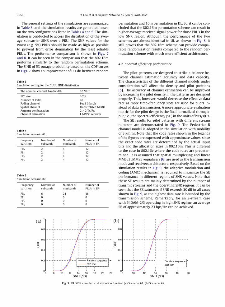
The general settings of the simulations are summarizedin Table 3, and the simulation results are generated basedon the two configurations listed in Tables 4 and 5. The sim-ulation is conducted to access the distribution of the aver-age subcarrier SINR over a PRU. The SNR values for theworst (e.g. 5%) PRUs should be made as high as possibleto prevent from error domination by the least reliablePRUs. The performance comparison is shown in Figs. 7and 8. It can be seen in the comparison that the 802.16mperforms similarly to the random permutation scheme.The SINR of 5% outage probability based on the CDF curvesin Figs. 7 show an improvement of 0.1 dB between random
Table 5Simulation scenario #2.
Frequencypartition
Number ofsubbands
Number ofminibands
Number ofPRUs in FPi
FP0 6 24 48FP1 0 0 0FP2 0 0 0FP3 0 0 0
6 8 10 12 14 16 18 20 220
0.2
0.4
0.6
0.8
1
SNR (dB)
CD
F
Random sequence
802.16m
CD
F
(a) (b
Fig. 7. DL SINR cumulative distribution func
Table 3Simulation setting for the DL/UL SINR distribution.
The nominal channel bandwidth 10 MHz
FFT size 1024Number of PRUs 48Fading channel PedB 3 km/hSpatial channel Uncorrelated MIMOAntenna configuration 2 � 2 Tx/RxChannel estimation L MMSE receiver
Table 4Simulation scenario #1.
Frequencypartition
Number ofsubbands
Number ofminibands
Number ofPRUs in FPi
FP0 2 4 12FP1 2 4 12FP2 2 4 12FP3 2 4 12
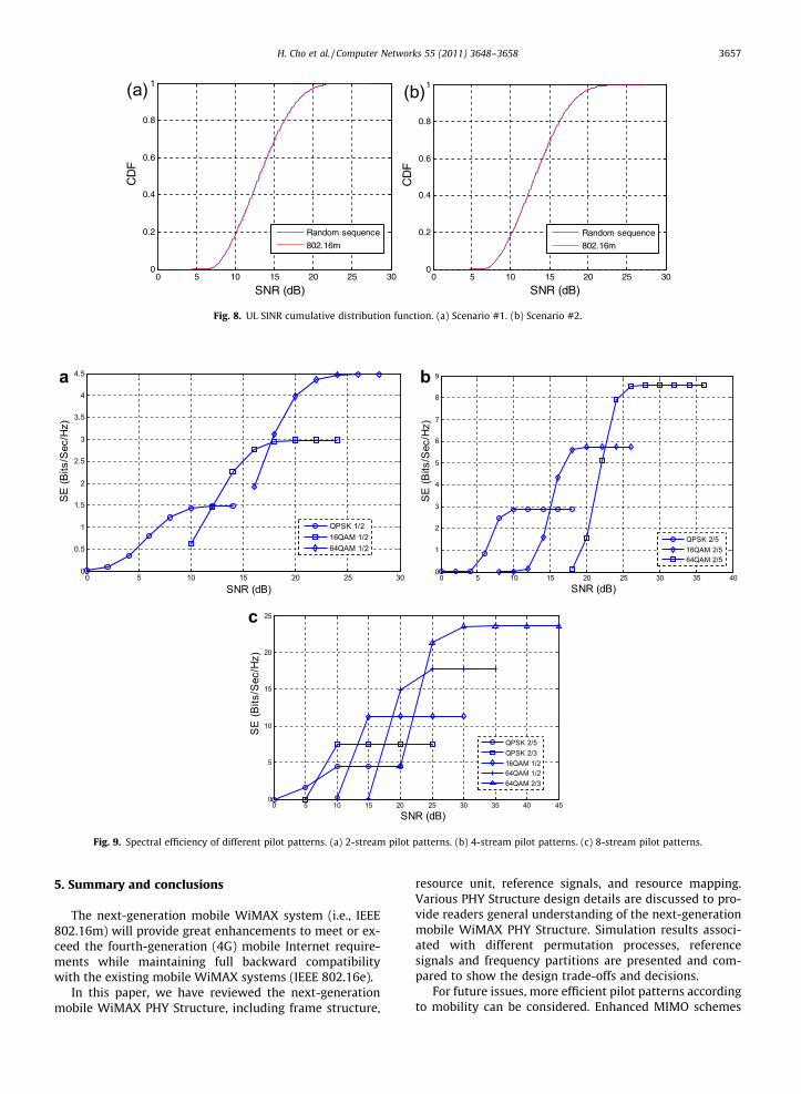
permutation and 16m permutation in DL. So, it can be con-cluded that the 802.16m permutation scheme can result inhigher average received signal power for those PRUs in thelow SNR region. Although the performance of the twoschemes are almost identical in UL as shown in Fig. 8, itstill proves that the 802.16m scheme can provide compa-rable randomization results compared to the random per-mutation scheme with much more efficient architecture.
4.2. Spectral efficiency performance
The pilot patterns are designed to strike a balance be-tween channel estimation accuracy and data capacity.The characteristics of the different channel models underconsideration will affect the density and pilot positions[5]. The accuracy of channel estimation can be improvedby increasing the pilot density, if the patterns are designedproperly. This, however, would decrease the effective datarate as more time–frequency slots are used for pilots in-stead of data transmission. A more appropriate evaluationmetric for the pilot design is the final normalized through-put, i.e., the spectral efficiency (SE) in the units of bits/s/Hz.
The SE results for pilot patterns with different streamnumbers are demonstrated in Fig. 9. The Pedestrian-Bchannel model is adopted in the simulation with mobilityof 3 km/hr. Note that the code rates shown in the legendsof the figures are expressed with approximate values, sincethe exact code rates are determined by the actual inputbits and the allocation sizes in 802.16m. This is differentto the case in 802.16e where the code rates are predeter-mined. It is assumed that spatial multiplexing and linearMMSE (LMMSE) equalizers [6] are used as the transmissionmode and receivers architecture, respectively. Based on thesimulation results in Fig. 9, the adaptive modulation andcoding (AMC) mechanism is required to maximize the SEperformance in different regions of SNR values. Note thatthese SE results are mainly determined by the number oftransmit streams and the operating SNR regions. It can beseen that the SE saturates if SNR exceeds 30 dB in all casesshown in Fig. 9, as the highest data rate is bounded by thetransmission scheme. Remarkably, for an 8-stream casewith 64QAM-2/3 operating in high SNR regime, an averageSE of approximately 23 bps/Hz can be achieved.
8 10 12 14 16 18 200
0.2
0.4
0.6
0.8
1
SNR (dB)
Random sequence
802.16m
)
tion (a) Scenario #1. (b) Scenario #2.
0 5 10 15 20 25 300
0.2
0.4
0.6
0.8
1
SNR (dB)
CD
F
Random sequence
802.16m
0 5 10 15 20 25 300
0.2
0.4
0.6
0.8
1
SNR (dB)
CD
F
Random sequence
802.16m
(a) (b)
Fig. 8. UL SINR cumulative distribution function. (a) Scenario #1. (b) Scenario #2.
0 5 10 15 20 25 300
0.5
1
1.5
2
2.5
3
3.5
4
4.5
SNR (dB)
SE
(Bits
/Sec
/Hz)
QPSK 1/216QAM 1/264QAM 1/2
0 5 10 15 20 25 30 35 400
1
2
3
4
5
6
7
8
9
SNR (dB)
SE
(Bits
/Sec
/Hz)
QPSK 2/516QAM 2/564QAM 2/5
0 5 10 15 20 25 30 35 40 450
5
10
15
20
25
SNR (dB)
SE
(Bits
/Sec
/Hz)
QPSK 2/5QPSK 2/316QAM 1/264QAM 1/264QAM 2/3
a b
c
Fig. 9. Spectral efficiency of different pilot patterns. (a) 2-stream pilot patterns. (b) 4-stream pilot patterns. (c) 8-stream pilot patterns.
H. Cho et al. / Computer Networks 55 (2011) 3648–3658 3657
5. Summary and conclusions
The next-generation mobile WiMAX system (i.e., IEEE802.16m) will provide great enhancements to meet or ex-ceed the fourth-generation (4G) mobile Internet require-ments while maintaining full backward compatibilitywith the existing mobile WiMAX systems (IEEE 802.16e).
In this paper, we have reviewed the next-generationmobile WiMAX PHY Structure, including frame structure,
resource unit, reference signals, and resource mapping.Various PHY Structure design details are discussed to pro-vide readers general understanding of the next-generationmobile WiMAX PHY Structure. Simulation results associ-ated with different permutation processes, referencesignals and frequency partitions are presented and com-pared to show the design trade-offs and decisions.
For future issues, more efficient pilot patterns accordingto mobility can be considered. Enhanced MIMO schemes
3658 H. Cho et al. / Computer Networks 55 (2011) 3648–3658
such as remote radio head (RRH) can be considered. More-over, coexistence between heterogeneous systems withdifferent physical structures can be an issue from the per-spective of interference mitigation.
For readers who are interested in full detailed designs ofthe next generation mobile WiMAX technologies, pleasereferred to [2] for further information.
References
[1] Report ITU-R M.2134, Requirements related to technical systemperformance for IMTAdvanced radio interface(s), November 2008.<http://www.itu.int/publ/R-REP-M.2134-2008/en>.
[2] Amendment to IEEE Standard for Local and Metropolitan AreaNetworks – Part 16: Air Interface for Broadband Wireless AccessSystems – Advanced Air Interface.
[3] IEEE Standard for Local and metropolitan area networks – Part 16: AirInterface for Broadband Wireless Access Systems – Advanced AirInterface.
[4] IEEE 802.16m-09/0582r2, Proposed text for DL subcarrierpermutation and DL tile permutation.
[5] P. Hoeher, S. Kaiser and P. Robertson, ‘‘Two-Dimensional Pilot-Symbol-Aided Channel Estimation By Wiener Filtering,’’ in: Proceedings of IEEEICCASP, Munich, Germany, April 1997, pp. 1845–1848.
[6] J.J. van de Beek, O. Edfors, M. Sandell, S.K. Wilson, P.O. Borjesson,‘‘Onchannel estimation in OFDM systems,’’ in Proceedings of IEEEVehicular Technology Conference, vol. 2, July 1995, pp. 815–819.
HanGyu Cho received his B.S., M.S., and Ph.D.degrees in Electrical and Electronic Engineer-ing from Yonsei University, Seoul, Korea, in1999, 2001, and 2005, respectively. For twoyears from September 2005, he was with theWireless Networking and CommunicationsGroup (WNCG), The University of Texas atAustin as a post-doctoral research associate.Since August 2007, he has been working for4G Standardization and System ResearchGroup, Mobile Communication TechnologyResearch Lab., LG Electronics. His research
interests include IEEE 802.16m, WiMAX and LTE/LTE-A standardizationand related technology development. Specifically, he has been activelycontributing to IEEE 802.16m in various areas such as PHY structure,
frame Structure, power control, and interference management.Taeyoung Kim received his B.S., M.S., andPh.D. degrees in Electrical and ElectronicEngineering from Yonsei University, Seoul,Korea, in 1998, 2000, and 2005, respectively.Since August 2005, he has been working forSamsung Electronics. His research interestsinclude IEEE 802.16m, WiMAX standardiza-tion and related technology development.Specifically, he has been actively contributingto IEEE 802.16m in various areas such asframe Structure, PHY structure, and MIMOscheme.
Yu-Tao Hsieh received his B.S., M.S. and Ph.D.degrees in Communication Engineering fromNational Chiao Tung University, Hsinchu,Taiwan, in 1995, 1997 and 2004, respectively.Since 2005, he joined the Computer andCommunications Labs of Industrial Technol-ogy Research Institute. He has been partici-pating in the standardization activity of IEEE802.16m project since 2007 in the area of PHYstructures. His research interest includesinterference mitigation, estimation theoryand adaptive signal processing.
Jong-Kae (J.K.) Fwu received his M.S. andPh.D. in Electrical Engineering from the StateUniversity of New York (SUNY) at StonyBrook. Jong-Kae (J.K.) Fwu presently serves asthe vice-chair of IEEE 802.16 Task Group m(TGm), a task group focusing on defining nextgeneration WiMAX for mobile internet evo-lution. He is also an Assistant Technical Editorof the IEEE 802.16m Mobile BroadbandWireless Standard – Advanced Air interface.He has been actively contributing to IEEE802.16m and the WiMAX Forum in various
areas such as PHY Structure, UL Control, multicast/broadcast services andmulticarrier operation.
Related Documents