S.O. Kasap, Optoelectronics and Photonics: Principles and Practices, Second Edition, © 2013 Pearson Education © 2013 Pearson Education, Inc., Upper Saddle River, NJ. All rights reserved. This publication is protected by Copyright and written permission should be obtained from the publisher prior to any prohibited reproduction, storage in a retrieval system, or transmission in any form or by any means, electronic, mechanical, photocopying, recording, or likewise. For information regarding permission(s), write to: Rights and Permissions Department, Pearson Education, Inc., Upper Saddle River, NJ 07458. Instructor’s Power Point for Optoelectronics and Photonics: Principles and Practices Second Edition ISBN-10: 0133081753 Second Edition Version 1.0237 [29 January 2013] A Complete Course in Power Point Chapter 1

Welcome message from author
This document is posted to help you gain knowledge. Please leave a comment to let me know what you think about it! Share it to your friends and learn new things together.
Transcript

S.O. Kasap, Optoelectronics and Photonics: Principles and Practices, Second Edition, © 2013 Pearson Education © 2013 Pearson Education, Inc., Upper Saddle River, NJ. All rights reserved. This publication is protected by Copyright and written permission should be obtained from the
publisher prior to any prohibited reproduction, storage in a retrieval system, or transmission in any form or by any means, electronic, mechanical, photocopying, recording, or likewise. For information regarding permission(s), write to: Rights and Permissions Department, Pearson Education, Inc., Upper Saddle River, NJ 07458.
Instructor’s Power Point for Optoelectronics and
Photonics: Principles and Practices
Second Edition
ISBN-10: 0133081753 Second Edition Version 1.0237
[29 January 2013]
A Complete Course in Power Point
Chapter 1
S.O. Kasap, Optoelectronics and Photonics: Principles and Practices, Second Edition, © 2013 Pearson Education © 2013 Pearson Education, Inc., Upper Saddle River, NJ. All rights reserved. This publication is protected by Copyright and written permission should be obtained from the
publisher prior to any prohibited reproduction, storage in a retrieval system, or transmission in any form or by any means, electronic, mechanical, photocopying, recording, or likewise. For information regarding permission(s), write to: Rights and Permissions Department, Pearson Education, Inc., Upper Saddle River, NJ 07458.
Updates and Corrected Slides
Class Demonstrations
Class Problems
Check author’s website http://optoelectronics.usask.ca
Email errors and corrections to [email protected]
S.O. Kasap, Optoelectronics and Photonics: Principles and Practices, Second Edition, © 2013 Pearson Education © 2013 Pearson Education, Inc., Upper Saddle River, NJ. All rights reserved. This publication is protected by Copyright and written permission should be obtained from the
publisher prior to any prohibited reproduction, storage in a retrieval system, or transmission in any form or by any means, electronic, mechanical, photocopying, recording, or likewise. For information regarding permission(s), write to: Rights and Permissions Department, Pearson Education, Inc., Upper Saddle River, NJ 07458.
This Power Point presentation is a copyrighted supplemental material to the textbook
Optoelectronics and Photonics: Principles & Practices, Second Edition, S. O. Kasap,
Pearson Education (USA), ISBN-10: 0132151499, ISBN-13: 9780132151498. © 2013
Pearson Education. Permission is given to instructors to use these Power Point slides in
their lectures provided that the above book has been adopted as a primary required
textbook for the course. Slides may be used in research seminars at research meetings,
symposia and conferences provided that the author, book title, and copyright information
are clearly displayed under each figure. It is unlawful to use the slides for teaching if the
textbook is not a required primary book for the course. The slides cannot be distributed
in any form whatsoever, especially on the internet, without the written permission of
Pearson Education.
Copyright Information and Permission: Part I
Please report typos and errors directly to the author: [email protected]
S.O. Kasap, Optoelectronics and Photonics: Principles and Practices, Second Edition, © 2013 Pearson Education © 2013 Pearson Education, Inc., Upper Saddle River, NJ. All rights reserved. This publication is protected by Copyright and written permission should be obtained from the
publisher prior to any prohibited reproduction, storage in a retrieval system, or transmission in any form or by any means, electronic, mechanical, photocopying, recording, or likewise. For information regarding permission(s), write to: Rights and Permissions Department, Pearson Education, Inc., Upper Saddle River, NJ 07458.
This Power Point presentation is a copyrighted supplemental material to the textbook
Optoelectronics and Photonics: Principles & Practices, Second Edition, S. O. Kasap,
Pearson Education (USA), ISBN-10: 0132151499, ISBN-13: 9780132151498. © 2013
Pearson Education. The slides cannot be distributed in any form whatsoever,
electronically or in print form, without the written permission of Pearson Education. It is
unlawful to post these slides, or part of a slide or slides, on the internet.
Copyright © 2013, 2001 by Pearson Education, Inc., Upper Saddle River, New Jersey,
07458. All rights reserved. Printed in the United States of America. This publication is
protected by Copyright and permission should be obtained from the publisher prior to
any prohibited reproduction, storage in a retrieval system, or transmission in any form or
by any means, electronic, mechanical, photocopying, recording, or likewise. For
information regarding permission(s), write to: Rights and Permissions Department.
Copyright Information and Permission: Part II
PEARSON

S.O. Kasap, Optoelectronics and Photonics: Principles and Practices, Second Edition, © 2013 Pearson Education © 2013 Pearson Education, Inc., Upper Saddle River, NJ. All rights reserved. This publication is protected by Copyright and written permission should be obtained from the
publisher prior to any prohibited reproduction, storage in a retrieval system, or transmission in any form or by any means, electronic, mechanical, photocopying, recording, or likewise. For information regarding permission(s), write to: Rights and Permissions Department, Pearson Education, Inc., Upper Saddle River, NJ 07458.
Important Note
You may use color illustrations from this Power Point
in your research-related seminars or research-related
presentations at scientific or technical meetings,
symposia or conferences provided that you fully cite
the following reference under each figure
From: S.O. Kasap, Optoelectronics and Photonics: Principles and Practices, Second Edition, © 2013 Pearson Education, USA
S.O. Kasap, Optoelectronics and Photonics: Principles and Practices, Second Edition, © 2013 Pearson Education © 2013 Pearson Education, Inc., Upper Saddle River, NJ. All rights reserved. This publication is protected by Copyright and written permission should be obtained from the
publisher prior to any prohibited reproduction, storage in a retrieval system, or transmission in any form or by any means, electronic, mechanical, photocopying, recording, or likewise. For information regarding permission(s), write to: Rights and Permissions Department, Pearson Education, Inc., Upper Saddle River, NJ 07458.
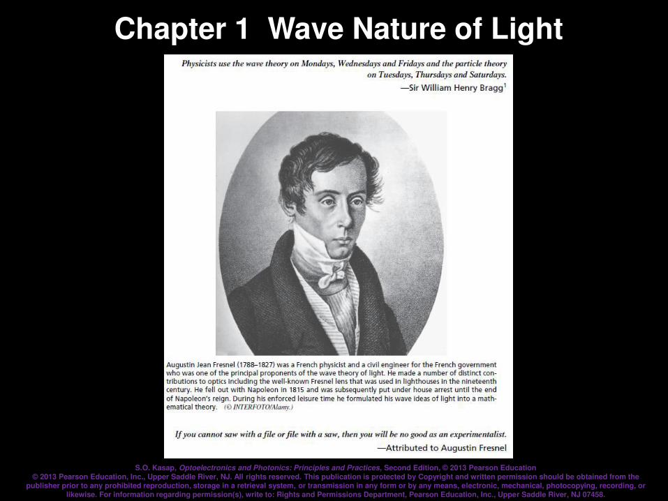
Chapter 1 Wave Nature of Light
S.O. Kasap, Optoelectronics and Photonics: Principles and Practices, Second Edition, © 2013 Pearson Education © 2013 Pearson Education, Inc., Upper Saddle River, NJ. All rights reserved. This publication is protected by Copyright and written permission should be obtained from the
publisher prior to any prohibited reproduction, storage in a retrieval system, or transmission in any form or by any means, electronic, mechanical, photocopying, recording, or likewise. For information regarding permission(s), write to: Rights and Permissions Department, Pearson Education, Inc., Upper Saddle River, NJ 07458.
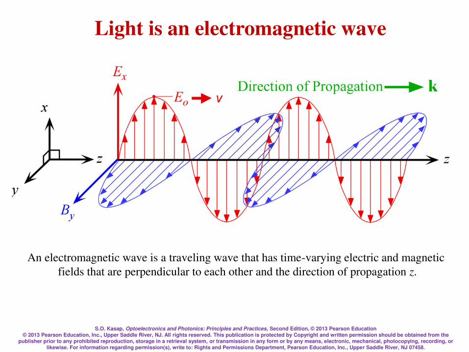
Light is an electromagnetic wave
An electromagnetic wave is a traveling wave that has time-varying electric and magnetic
fields that are perpendicular to each other and the direction of propagation z.
S.O. Kasap, Optoelectronics and Photonics: Principles and Practices, Second Edition, © 2013 Pearson Education © 2013 Pearson Education, Inc., Upper Saddle River, NJ. All rights reserved. This publication is protected by Copyright and written permission should be obtained from the
publisher prior to any prohibited reproduction, storage in a retrieval system, or transmission in any form or by any means, electronic, mechanical, photocopying, recording, or likewise. For information regarding permission(s), write to: Rights and Permissions Department, Pearson Education, Inc., Upper Saddle River, NJ 07458.
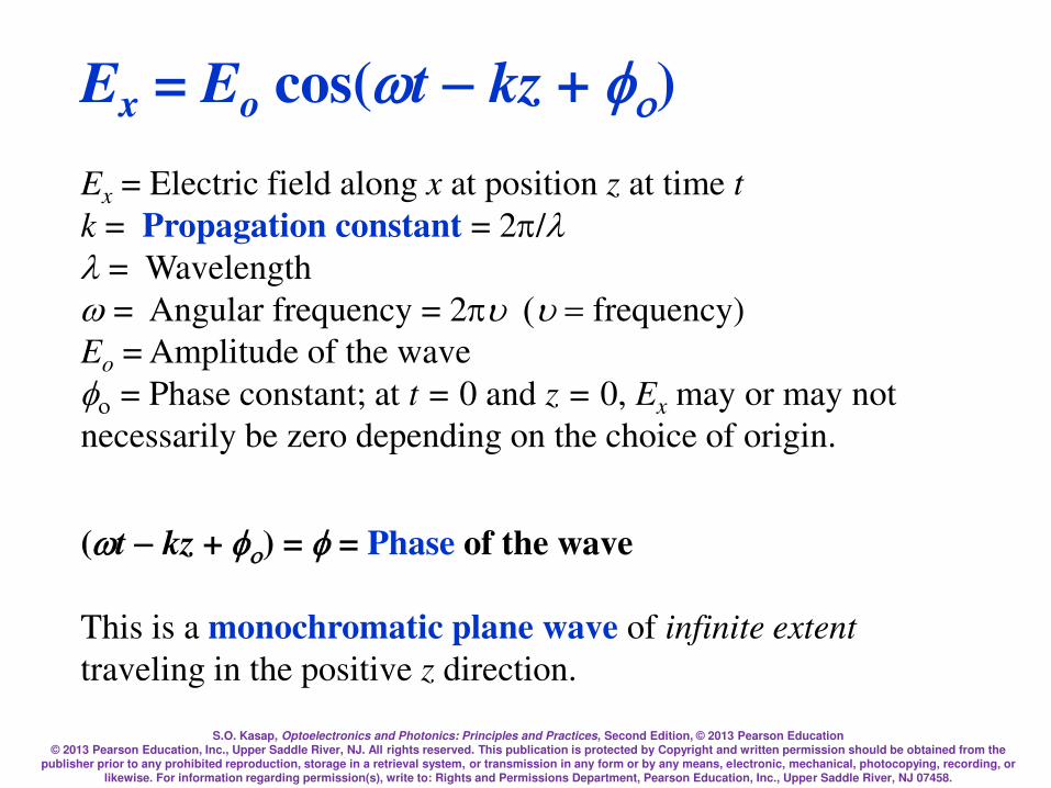
Ex = Eo cos(tkz + )
Ex = Electric field along x at position z at time t
k = Propagation constant = 2/
= Wavelength
= Angular frequency = 2u(u=frequency)
Eo = Amplitude of the wave
= Phase constant; at t = 0 and z = 0, Ex may or may not
necessarily be zero depending on the choice of origin.
(tkz + ) = = Phase of the wave
This is a monochromatic plane wave of infinite extent
traveling in the positive z direction.
S.O. Kasap, Optoelectronics and Photonics: Principles and Practices, Second Edition, © 2013 Pearson Education © 2013 Pearson Education, Inc., Upper Saddle River, NJ. All rights reserved. This publication is protected by Copyright and written permission should be obtained from the
publisher prior to any prohibited reproduction, storage in a retrieval system, or transmission in any form or by any means, electronic, mechanical, photocopying, recording, or likewise. For information regarding permission(s), write to: Rights and Permissions Department, Pearson Education, Inc., Upper Saddle River, NJ 07458.
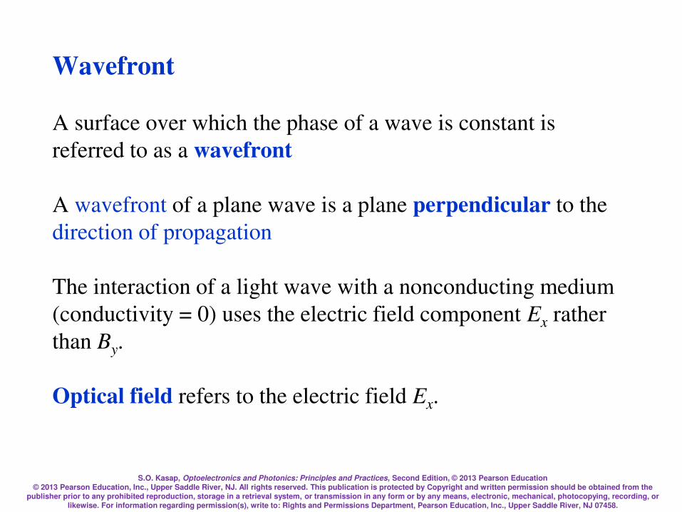
Wavefront
A surface over which the phase of a wave is constant is
referred to as a wavefront
A wavefront of a plane wave is a plane perpendicular to the
direction of propagation
The interaction of a light wave with a nonconducting medium
(conductivity = 0) uses the electric field component Ex rather
than By.
Optical field refers to the electric field Ex.

S.O. Kasap, Optoelectronics and Photonics: Principles and Practices, Second Edition, © 2013 Pearson Education © 2013 Pearson Education, Inc., Upper Saddle River, NJ. All rights reserved. This publication is protected by Copyright and written permission should be obtained from the
publisher prior to any prohibited reproduction, storage in a retrieval system, or transmission in any form or by any means, electronic, mechanical, photocopying, recording, or likewise. For information regarding permission(s), write to: Rights and Permissions Department, Pearson Education, Inc., Upper Saddle River, NJ 07458.
A plane EM wave traveling along z, has the same Ex (or By) at any point in a given xy plane.
All electric field vectors in a given xy plane are therefore in phase. The xy planes are of
infinite extent in the x and y directions.

S.O. Kasap, Optoelectronics and Photonics: Principles and Practices, Second Edition, © 2013 Pearson Education © 2013 Pearson Education, Inc., Upper Saddle River, NJ. All rights reserved. This publication is protected by Copyright and written permission should be obtained from the
publisher prior to any prohibited reproduction, storage in a retrieval system, or transmission in any form or by any means, electronic, mechanical, photocopying, recording, or likewise. For information regarding permission(s), write to: Rights and Permissions Department, Pearson Education, Inc., Upper Saddle River, NJ 07458.
The time and space evolution of a given phase , for example
that corresponding to a maximum field is described by
= tkz + = constant
During a time interval t, this constant phase (and hence the
maximum field) moves a distance z. The phase velocity of this
wave is therefore z/t. The phase velocity v is
u
===kt
zv
Phase Velocity

S.O. Kasap, Optoelectronics and Photonics: Principles and Practices, Second Edition, © 2013 Pearson Education © 2013 Pearson Education, Inc., Upper Saddle River, NJ. All rights reserved. This publication is protected by Copyright and written permission should be obtained from the
publisher prior to any prohibited reproduction, storage in a retrieval system, or transmission in any form or by any means, electronic, mechanical, photocopying, recording, or likewise. For information regarding permission(s), write to: Rights and Permissions Department, Pearson Education, Inc., Upper Saddle River, NJ 07458.
The phase difference between two points separated
by z is simply kz
since t is the same for each point
If this phase difference is 0 or multiples of 2 then
the two points are in phase. Thus, the phase
difference can be expressed as kz or 2z/
Phase change over a distance z
= tkz +
= kz
S.O. Kasap, Optoelectronics and Photonics: Principles and Practices, Second Edition, © 2013 Pearson Education © 2013 Pearson Education, Inc., Upper Saddle River, NJ. All rights reserved. This publication is protected by Copyright and written permission should be obtained from the
publisher prior to any prohibited reproduction, storage in a retrieval system, or transmission in any form or by any means, electronic, mechanical, photocopying, recording, or likewise. For information regarding permission(s), write to: Rights and Permissions Department, Pearson Education, Inc., Upper Saddle River, NJ 07458.
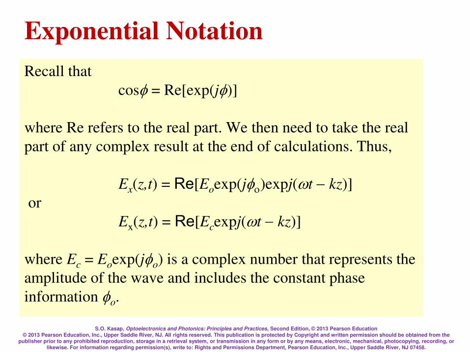
Recall that
cos= Re[exp(j)]
where Re refers to the real part. We then need to take the real
part of any complex result at the end of calculations. Thus,
Ex(z,t) = Re[Eoexp(j)expj(tkz)]
or
Ex(z,t) = Re[Ecexpj(tkz)]
where Ec = Eoexp(jo) is a complex number that represents the
amplitude of the wave and includes the constant phase
information o.
Exponential Notation
S.O. Kasap, Optoelectronics and Photonics: Principles and Practices, Second Edition, © 2013 Pearson Education © 2013 Pearson Education, Inc., Upper Saddle River, NJ. All rights reserved. This publication is protected by Copyright and written permission should be obtained from the
publisher prior to any prohibited reproduction, storage in a retrieval system, or transmission in any form or by any means, electronic, mechanical, photocopying, recording, or likewise. For information regarding permission(s), write to: Rights and Permissions Department, Pearson Education, Inc., Upper Saddle River, NJ 07458.
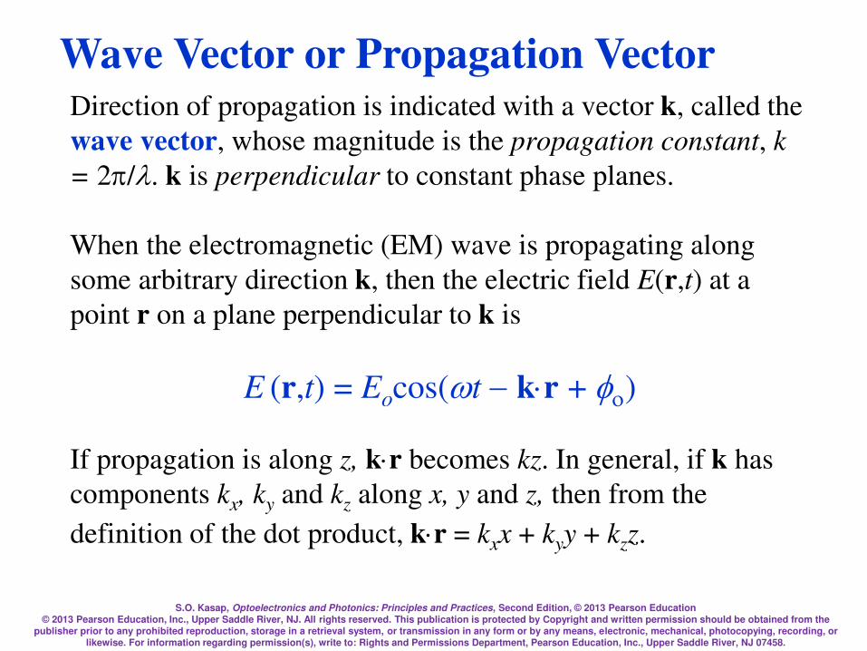
Direction of propagation is indicated with a vector k, called the
wave vector, whose magnitude is the propagation constant, k
= 2/. k is perpendicular to constant phase planes.
When the electromagnetic (EM) wave is propagating along
some arbitrary direction k, then the electric field E(r,t) at a
point r on a plane perpendicular to k is
E (r,t) = Eocos(tkr + )
If propagation is along z, kr becomes kz. In general, if k has
components kx, ky and kz along x, y and z, then from the
definition of the dot product, kr = kxx + kyy + kzz.
Wave Vector or Propagation Vector
S.O. Kasap, Optoelectronics and Photonics: Principles and Practices, Second Edition, © 2013 Pearson Education © 2013 Pearson Education, Inc., Upper Saddle River, NJ. All rights reserved. This publication is protected by Copyright and written permission should be obtained from the
publisher prior to any prohibited reproduction, storage in a retrieval system, or transmission in any form or by any means, electronic, mechanical, photocopying, recording, or likewise. For information regarding permission(s), write to: Rights and Permissions Department, Pearson Education, Inc., Upper Saddle River, NJ 07458.
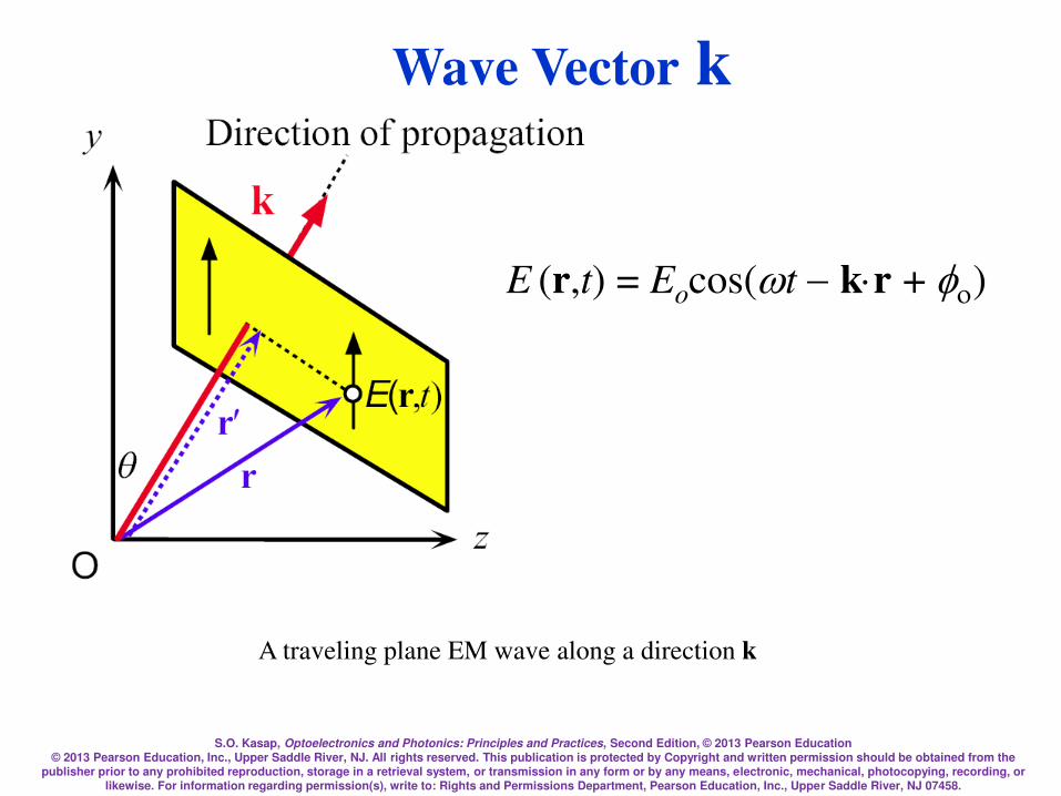
Wave Vector k
A traveling plane EM wave along a direction k
E (r,t) = Eocos(tkr + )
S.O. Kasap, Optoelectronics and Photonics: Principles and Practices, Second Edition, © 2013 Pearson Education © 2013 Pearson Education, Inc., Upper Saddle River, NJ. All rights reserved. This publication is protected by Copyright and written permission should be obtained from the
publisher prior to any prohibited reproduction, storage in a retrieval system, or transmission in any form or by any means, electronic, mechanical, photocopying, recording, or likewise. For information regarding permission(s), write to: Rights and Permissions Department, Pearson Education, Inc., Upper Saddle River, NJ 07458.
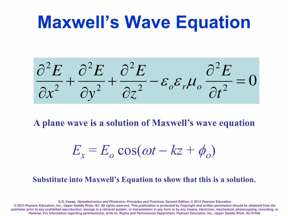
Maxwell’s Wave Equation
02
2
2
2
2
2
2
2
=
t
E
z
E
y
E
x
Eoro
Ex = Eo cos(tkz + )
A plane wave is a solution of Maxwell’s wave equation
Substitute into Maxwell’s Equation to show that this is a solution.
S.O. Kasap, Optoelectronics and Photonics: Principles and Practices, Second Edition, © 2013 Pearson Education © 2013 Pearson Education, Inc., Upper Saddle River, NJ. All rights reserved. This publication is protected by Copyright and written permission should be obtained from the
publisher prior to any prohibited reproduction, storage in a retrieval system, or transmission in any form or by any means, electronic, mechanical, photocopying, recording, or likewise. For information regarding permission(s), write to: Rights and Permissions Department, Pearson Education, Inc., Upper Saddle River, NJ 07458.
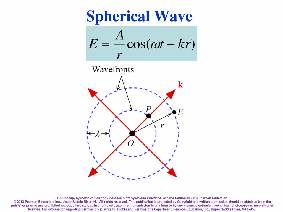
Spherical Wave
)cos( krtr
AE =

S.O. Kasap, Optoelectronics and Photonics: Principles and Practices, Second Edition, © 2013 Pearson Education © 2013 Pearson Education, Inc., Upper Saddle River, NJ. All rights reserved. This publication is protected by Copyright and written permission should be obtained from the
publisher prior to any prohibited reproduction, storage in a retrieval system, or transmission in any form or by any means, electronic, mechanical, photocopying, recording, or likewise. For information regarding permission(s), write to: Rights and Permissions Department, Pearson Education, Inc., Upper Saddle River, NJ 07458.
Examples of possible EM waves
Optical divergence refers to the angular separation of wave
vectors on a given wavefront.
S.O. Kasap, Optoelectronics and Photonics: Principles and Practices, Second Edition, © 2013 Pearson Education © 2013 Pearson Education, Inc., Upper Saddle River, NJ. All rights reserved. This publication is protected by Copyright and written permission should be obtained from the
publisher prior to any prohibited reproduction, storage in a retrieval system, or transmission in any form or by any means, electronic, mechanical, photocopying, recording, or likewise. For information regarding permission(s), write to: Rights and Permissions Department, Pearson Education, Inc., Upper Saddle River, NJ 07458.
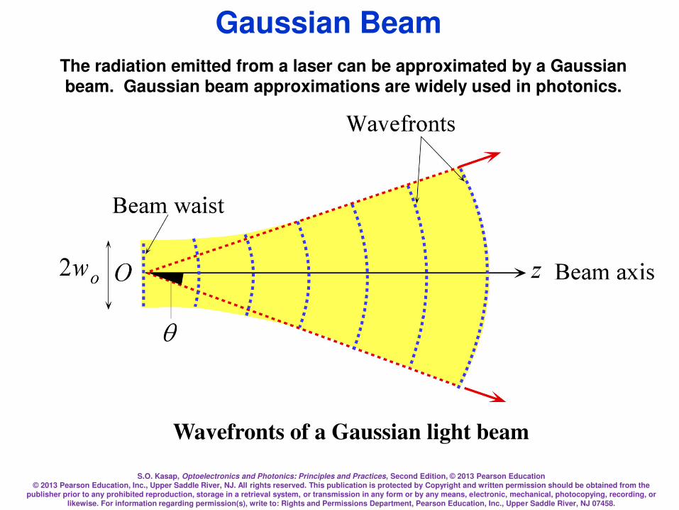
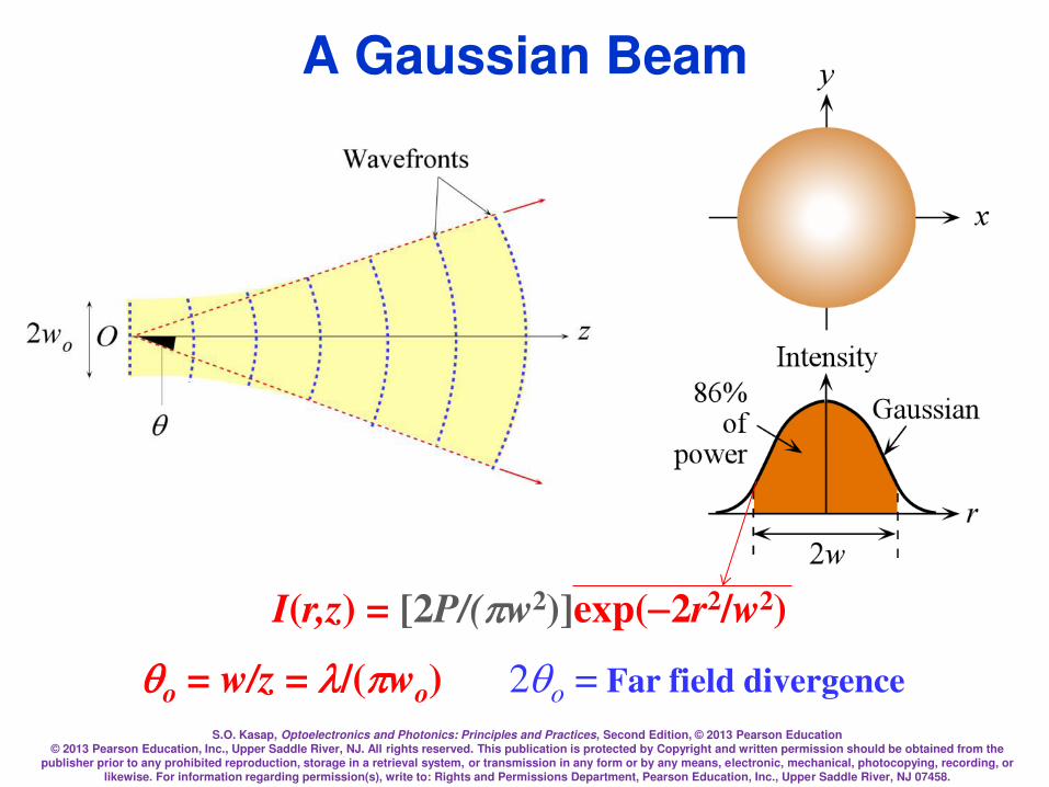
Gaussian Beam
Wavefronts of a Gaussian light beam
The radiation emitted from a laser can be approximated by a Gaussian beam. Gaussian beam approximations are widely used in photonics.
S.O. Kasap, Optoelectronics and Photonics: Principles and Practices, Second Edition, © 2013 Pearson Education © 2013 Pearson Education, Inc., Upper Saddle River, NJ. All rights reserved. This publication is protected by Copyright and written permission should be obtained from the
publisher prior to any prohibited reproduction, storage in a retrieval system, or transmission in any form or by any means, electronic, mechanical, photocopying, recording, or likewise. For information regarding permission(s), write to: Rights and Permissions Department, Pearson Education, Inc., Upper Saddle River, NJ 07458.
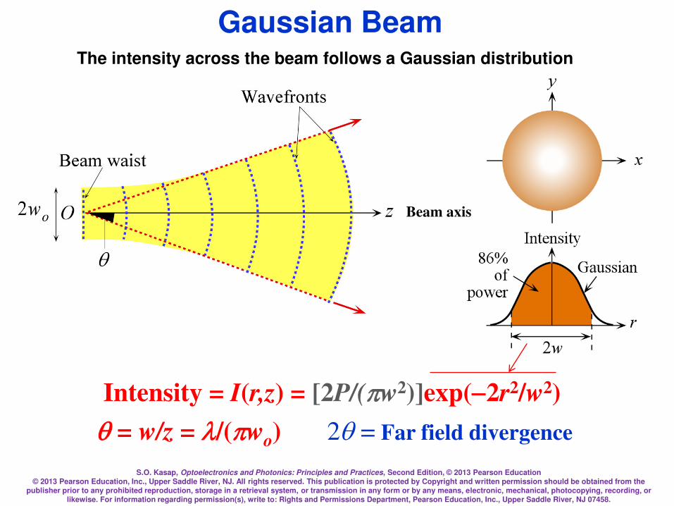
Gaussian Beam
Intensity = I(r,z) = [2P/(w2)]exp(2r2/w2)
q= w/z = /(wo) 2q = Far field divergence
The intensity across the beam follows a Gaussian distribution
Beam axis
S.O. Kasap, Optoelectronics and Photonics: Principles and Practices, Second Edition, © 2013 Pearson Education © 2013 Pearson Education, Inc., Upper Saddle River, NJ. All rights reserved. This publication is protected by Copyright and written permission should be obtained from the
publisher prior to any prohibited reproduction, storage in a retrieval system, or transmission in any form or by any means, electronic, mechanical, photocopying, recording, or likewise. For information regarding permission(s), write to: Rights and Permissions Department, Pearson Education, Inc., Upper Saddle River, NJ 07458.
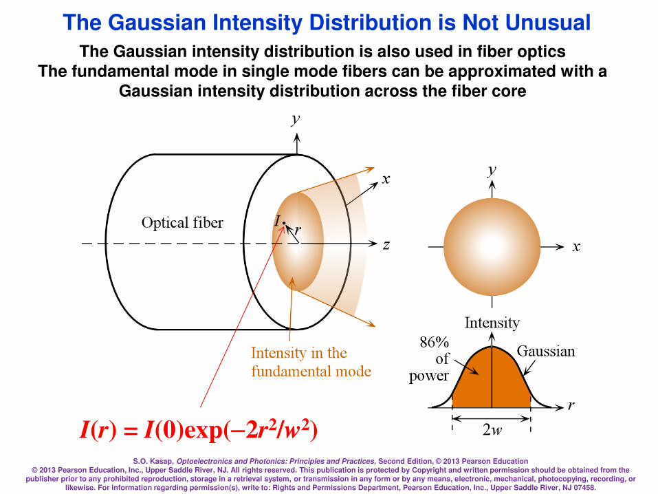
The Gaussian Intensity Distribution is Not Unusual
I(r) = I(0)exp(2r2/w2)
The Gaussian intensity distribution is also used in fiber optics The fundamental mode in single mode fibers can be approximated with a
Gaussian intensity distribution across the fiber core

S.O. Kasap, Optoelectronics and Photonics: Principles and Practices, Second Edition, © 2013 Pearson Education © 2013 Pearson Education, Inc., Upper Saddle River, NJ. All rights reserved. This publication is protected by Copyright and written permission should be obtained from the
publisher prior to any prohibited reproduction, storage in a retrieval system, or transmission in any form or by any means, electronic, mechanical, photocopying, recording, or likewise. For information regarding permission(s), write to: Rights and Permissions Department, Pearson Education, Inc., Upper Saddle River, NJ 07458.
Gaussian Beam
zo = wo2/
2q = Far field divergence
In optics and
especially laser science,
the Rayleigh
length or Rayleigh
range is the distance
along the propagation
direction of a beam from
the waist to the place
where the area of
the cross section is
doubled.[1] A related
parameter is
the confocal
parameter, b, which is
twice the Rayleigh
length.

S.O. Kasap, Optoelectronics and Photonics: Principles and Practices, Second Edition, © 2013 Pearson Education © 2013 Pearson Education, Inc., Upper Saddle River, NJ. All rights reserved. This publication is protected by Copyright and written permission should be obtained from the
publisher prior to any prohibited reproduction, storage in a retrieval system, or transmission in any form or by any means, electronic, mechanical, photocopying, recording, or likewise. For information regarding permission(s), write to: Rights and Permissions Department, Pearson Education, Inc., Upper Saddle River, NJ 07458.
2/12
2122
=
o
ow
zww
2
oo
wz =
Gaussian Beam
2/12
122
=
o
oz
zww
Rayleigh range
S.O. Kasap, Optoelectronics and Photonics: Principles and Practices, Second Edition, © 2013 Pearson Education © 2013 Pearson Education, Inc., Upper Saddle River, NJ. All rights reserved. This publication is protected by Copyright and written permission should be obtained from the
publisher prior to any prohibited reproduction, storage in a retrieval system, or transmission in any form or by any means, electronic, mechanical, photocopying, recording, or likewise. For information regarding permission(s), write to: Rights and Permissions Department, Pearson Education, Inc., Upper Saddle River, NJ 07458.
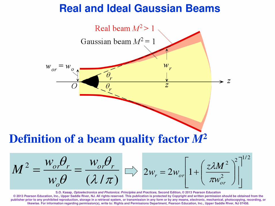
Real and Ideal Gaussian Beams
2/12
2
2
122
=
or
orrw
Mzww
)/(
2
q
qq ror
o
ror w
w
wM ==
Definition of a beam quality factor M2
S.O. Kasap, Optoelectronics and Photonics: Principles and Practices, Second Edition, © 2013 Pearson Education © 2013 Pearson Education, Inc., Upper Saddle River, NJ. All rights reserved. This publication is protected by Copyright and written permission should be obtained from the
publisher prior to any prohibited reproduction, storage in a retrieval system, or transmission in any form or by any means, electronic, mechanical, photocopying, recording, or likewise. For information regarding permission(s), write to: Rights and Permissions Department, Pearson Education, Inc., Upper Saddle River, NJ 07458.
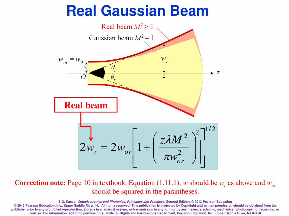
Real Gaussian Beam
2/12
2
2
122
=
or
orrw
Mzww
Real beam
Correction note: Page 10 in textbook, Equation (1.11.1), w should be wr as above and wor
should be squared in the parantheses.
S.O. Kasap, Optoelectronics and Photonics: Principles and Practices, Second Edition, © 2013 Pearson Education © 2013 Pearson Education, Inc., Upper Saddle River, NJ. All rights reserved. This publication is protected by Copyright and written permission should be obtained from the
publisher prior to any prohibited reproduction, storage in a retrieval system, or transmission in any form or by any means, electronic, mechanical, photocopying, recording, or likewise. For information regarding permission(s), write to: Rights and Permissions Department, Pearson Education, Inc., Upper Saddle River, NJ 07458.
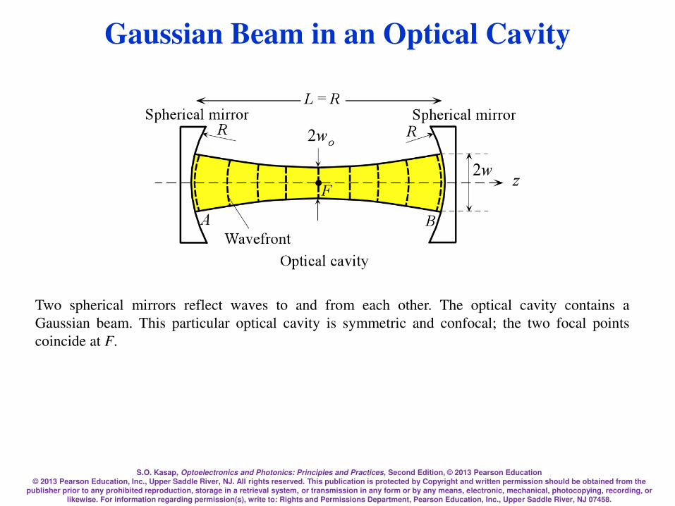
Two spherical mirrors reflect waves to and from each other. The optical cavity contains a
Gaussian beam. This particular optical cavity is symmetric and confocal; the two focal points
coincide at F.
Gaussian Beam in an Optical Cavity
S.O. Kasap, Optoelectronics and Photonics: Principles and Practices, Second Edition, © 2013 Pearson Education © 2013 Pearson Education, Inc., Upper Saddle River, NJ. All rights reserved. This publication is protected by Copyright and written permission should be obtained from the
publisher prior to any prohibited reproduction, storage in a retrieval system, or transmission in any form or by any means, electronic, mechanical, photocopying, recording, or likewise. For information regarding permission(s), write to: Rights and Permissions Department, Pearson Education, Inc., Upper Saddle River, NJ 07458.
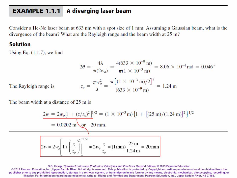
mm20m24.1
m25)mm1(2122
2/12
==
=
o
o
o
oz
zw
z
zww
S.O. Kasap, Optoelectronics and Photonics: Principles and Practices, Second Edition, © 2013 Pearson Education © 2013 Pearson Education, Inc., Upper Saddle River, NJ. All rights reserved. This publication is protected by Copyright and written permission should be obtained from the
publisher prior to any prohibited reproduction, storage in a retrieval system, or transmission in any form or by any means, electronic, mechanical, photocopying, recording, or likewise. For information regarding permission(s), write to: Rights and Permissions Department, Pearson Education, Inc., Upper Saddle River, NJ 07458.
Refractive Index
When an EM wave is traveling in a dielectric
medium, the oscillating electric field polarizes the
molecules of the medium at the frequency of the
wave
The stronger is the interaction between the field and
the dipoles, the slower is the propagation of the
wave
S.O. Kasap, Optoelectronics and Photonics: Principles and Practices, Second Edition, © 2013 Pearson Education © 2013 Pearson Education, Inc., Upper Saddle River, NJ. All rights reserved. This publication is protected by Copyright and written permission should be obtained from the
publisher prior to any prohibited reproduction, storage in a retrieval system, or transmission in any form or by any means, electronic, mechanical, photocopying, recording, or likewise. For information regarding permission(s), write to: Rights and Permissions Department, Pearson Education, Inc., Upper Saddle River, NJ 07458.
Refractive Index
S.O. Kasap, Optoelectronics and Photonics: Principles and Practices, Second Edition, © 2013 Pearson Education © 2013 Pearson Education, Inc., Upper Saddle River, NJ. All rights reserved. This publication is protected by Copyright and written permission should be obtained from the
publisher prior to any prohibited reproduction, storage in a retrieval system, or transmission in any form or by any means, electronic, mechanical, photocopying, recording, or likewise. For information regarding permission(s), write to: Rights and Permissions Department, Pearson Education, Inc., Upper Saddle River, NJ 07458.
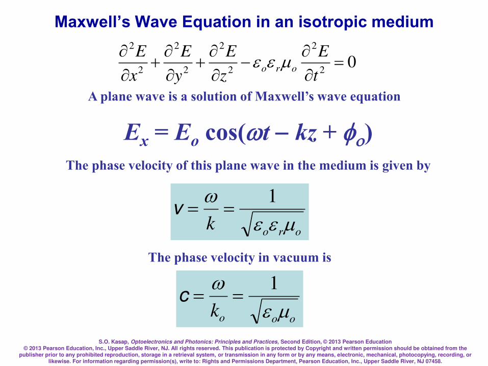
Maxwell’s Wave Equation in an isotropic medium
02
2
2
2
2
2
2
2
=
t
E
z
E
y
E
x
Eoro
Ex = Eo cos(tkz + ) A plane wave is a solution of Maxwell’s wave equation
orok 1==v
The phase velocity of this plane wave in the medium is given by
The phase velocity in vacuum is
oook 1
==c
S.O. Kasap, Optoelectronics and Photonics: Principles and Practices, Second Edition, © 2013 Pearson Education © 2013 Pearson Education, Inc., Upper Saddle River, NJ. All rights reserved. This publication is protected by Copyright and written permission should be obtained from the
publisher prior to any prohibited reproduction, storage in a retrieval system, or transmission in any form or by any means, electronic, mechanical, photocopying, recording, or likewise. For information regarding permission(s), write to: Rights and Permissions Department, Pearson Education, Inc., Upper Saddle River, NJ 07458.
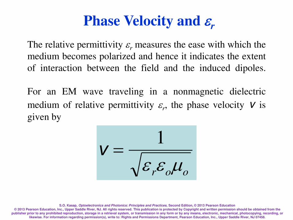
The relative permittivity r measures the ease with which the
medium becomes polarized and hence it indicates the extent
of interaction between the field and the induced dipoles.
For an EM wave traveling in a nonmagnetic dielectric
medium of relative permittivity r, the phase velocity v is
given by
Phase Velocity and r
oor 1
=ν
S.O. Kasap, Optoelectronics and Photonics: Principles and Practices, Second Edition, © 2013 Pearson Education © 2013 Pearson Education, Inc., Upper Saddle River, NJ. All rights reserved. This publication is protected by Copyright and written permission should be obtained from the
publisher prior to any prohibited reproduction, storage in a retrieval system, or transmission in any form or by any means, electronic, mechanical, photocopying, recording, or likewise. For information regarding permission(s), write to: Rights and Permissions Department, Pearson Education, Inc., Upper Saddle River, NJ 07458.
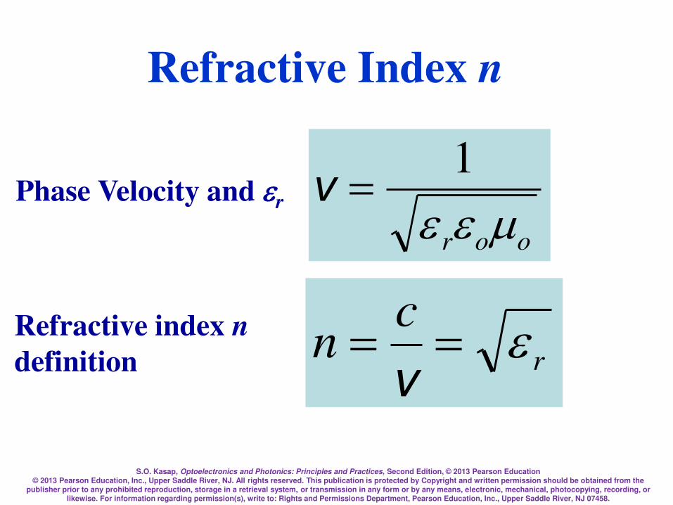
Phase Velocity and r
oor 1
=ν
r
cn ==
v
Refractive index n
definition
Refractive Index n
S.O. Kasap, Optoelectronics and Photonics: Principles and Practices, Second Edition, © 2013 Pearson Education © 2013 Pearson Education, Inc., Upper Saddle River, NJ. All rights reserved. This publication is protected by Copyright and written permission should be obtained from the
publisher prior to any prohibited reproduction, storage in a retrieval system, or transmission in any form or by any means, electronic, mechanical, photocopying, recording, or likewise. For information regarding permission(s), write to: Rights and Permissions Department, Pearson Education, Inc., Upper Saddle River, NJ 07458.
Optical frequencies
Typical frequencies that are involved in
optoelectronic devices are in the infrared (including
far infrared), visible, and UV, and we generically
refer to these frequencies as optical frequencies
Somewhat arbitrary range:
Roughly 1012 Hz to 1016 Hz

S.O. Kasap, Optoelectronics and Photonics: Principles and Practices, Second Edition, © 2013 Pearson Education © 2013 Pearson Education, Inc., Upper Saddle River, NJ. All rights reserved. This publication is protected by Copyright and written permission should be obtained from the
publisher prior to any prohibited reproduction, storage in a retrieval system, or transmission in any form or by any means, electronic, mechanical, photocopying, recording, or likewise. For information regarding permission(s), write to: Rights and Permissions Department, Pearson Education, Inc., Upper Saddle River, NJ 07458.
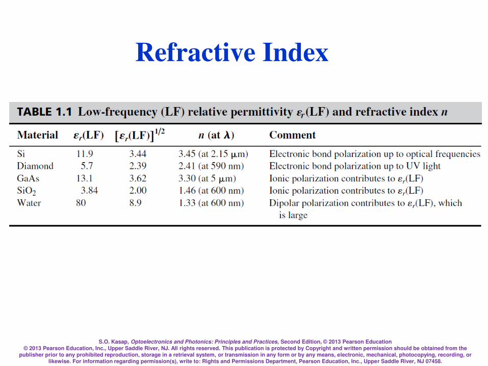
Low frequency (LF) relative permittivity r(LF) and
refractive index n.
S.O. Kasap, Optoelectronics and Photonics: Principles and Practices, Second Edition, © 2013 Pearson Education © 2013 Pearson Education, Inc., Upper Saddle River, NJ. All rights reserved. This publication is protected by Copyright and written permission should be obtained from the
publisher prior to any prohibited reproduction, storage in a retrieval system, or transmission in any form or by any means, electronic, mechanical, photocopying, recording, or likewise. For information regarding permission(s), write to: Rights and Permissions Department, Pearson Education, Inc., Upper Saddle River, NJ 07458.
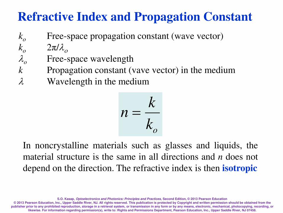
ko Free-space propagation constant (wave vector)
ko 2π/ o Free-space wavelength
k Propagation constant (vave vector) in the medium
Wavelength in the medium
ok
kn =
In noncrystalline materials such as glasses and liquids, the
material structure is the same in all directions and n does not
depend on the direction. The refractive index is then isotropic
Refractive Index and Propagation Constant

S.O. Kasap, Optoelectronics and Photonics: Principles and Practices, Second Edition, © 2013 Pearson Education © 2013 Pearson Education, Inc., Upper Saddle River, NJ. All rights reserved. This publication is protected by Copyright and written permission should be obtained from the
publisher prior to any prohibited reproduction, storage in a retrieval system, or transmission in any form or by any means, electronic, mechanical, photocopying, recording, or likewise. For information regarding permission(s), write to: Rights and Permissions Department, Pearson Education, Inc., Upper Saddle River, NJ 07458.
Refractive Index and Wavelength
medium = /n
kmedium = nk In free space
It is customary to drop the subscript o on k and
S.O. Kasap, Optoelectronics and Photonics: Principles and Practices, Second Edition, © 2013 Pearson Education © 2013 Pearson Education, Inc., Upper Saddle River, NJ. All rights reserved. This publication is protected by Copyright and written permission should be obtained from the
publisher prior to any prohibited reproduction, storage in a retrieval system, or transmission in any form or by any means, electronic, mechanical, photocopying, recording, or likewise. For information regarding permission(s), write to: Rights and Permissions Department, Pearson Education, Inc., Upper Saddle River, NJ 07458.
Crystals, in general, have nonisotropic, or
anisotropic, properties
Typically noncrystalline solids such as glasses and
liquids, and cubic crystals are optically isotropic;
they possess only one refractive index for all
directions
Refractive Index and Isotropy
S.O. Kasap, Optoelectronics and Photonics: Principles and Practices, Second Edition, © 2013 Pearson Education © 2013 Pearson Education, Inc., Upper Saddle River, NJ. All rights reserved. This publication is protected by Copyright and written permission should be obtained from the
publisher prior to any prohibited reproduction, storage in a retrieval system, or transmission in any form or by any means, electronic, mechanical, photocopying, recording, or likewise. For information regarding permission(s), write to: Rights and Permissions Department, Pearson Education, Inc., Upper Saddle River, NJ 07458.
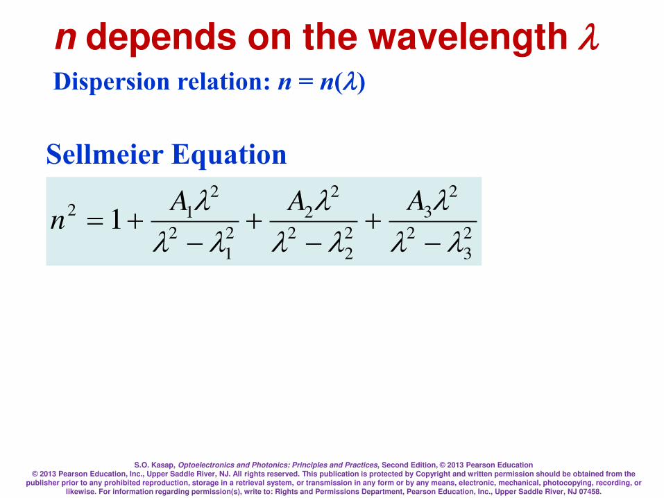
n depends on the wavelength Dispersion relation: n = n()
2
3
2
2
3
2
2
2
2
2
2
1
2
2
12 1
=
AAAn
Sellmeier Equation
S.O. Kasap, Optoelectronics and Photonics: Principles and Practices, Second Edition, © 2013 Pearson Education © 2013 Pearson Education, Inc., Upper Saddle River, NJ. All rights reserved. This publication is protected by Copyright and written permission should be obtained from the
publisher prior to any prohibited reproduction, storage in a retrieval system, or transmission in any form or by any means, electronic, mechanical, photocopying, recording, or likewise. For information regarding permission(s), write to: Rights and Permissions Department, Pearson Education, Inc., Upper Saddle River, NJ 07458.
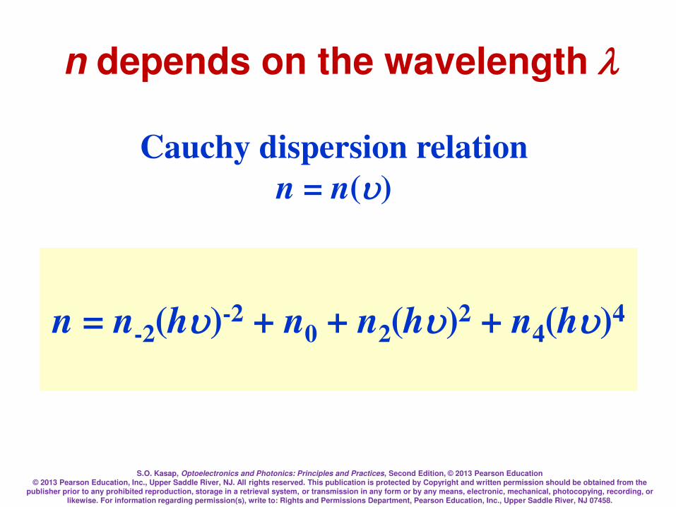
n depends on the wavelength
n = n-2(hu)-2 + n0 + n2(hu)2 + n4(hu)4
Cauchy dispersion relation
n = n(u)
S.O. Kasap, Optoelectronics and Photonics: Principles and Practices, Second Edition, © 2013 Pearson Education © 2013 Pearson Education, Inc., Upper Saddle River, NJ. All rights reserved. This publication is protected by Copyright and written permission should be obtained from the
publisher prior to any prohibited reproduction, storage in a retrieval system, or transmission in any form or by any means, electronic, mechanical, photocopying, recording, or likewise. For information regarding permission(s), write to: Rights and Permissions Department, Pearson Education, Inc., Upper Saddle River, NJ 07458.
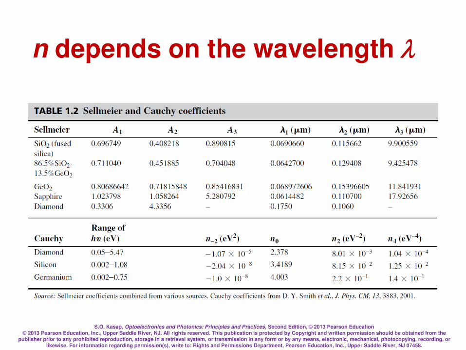
n depends on the wavelength
S.O. Kasap, Optoelectronics and Photonics: Principles and Practices, Second Edition, © 2013 Pearson Education © 2013 Pearson Education, Inc., Upper Saddle River, NJ. All rights reserved. This publication is protected by Copyright and written permission should be obtained from the
publisher prior to any prohibited reproduction, storage in a retrieval system, or transmission in any form or by any means, electronic, mechanical, photocopying, recording, or likewise. For information regarding permission(s), write to: Rights and Permissions Department, Pearson Education, Inc., Upper Saddle River, NJ 07458.
Group Velocity and Group Index
There are no perfect monochromatic
waves
We have to consider the way in which
a group of waves differing slightly in
wavelength travel along the z-direction
S.O. Kasap, Optoelectronics and Photonics: Principles and Practices, Second Edition, © 2013 Pearson Education © 2013 Pearson Education, Inc., Upper Saddle River, NJ. All rights reserved. This publication is protected by Copyright and written permission should be obtained from the
publisher prior to any prohibited reproduction, storage in a retrieval system, or transmission in any form or by any means, electronic, mechanical, photocopying, recording, or likewise. For information regarding permission(s), write to: Rights and Permissions Department, Pearson Education, Inc., Upper Saddle River, NJ 07458.
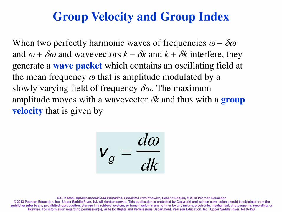
When two perfectly harmonic waves of frequencies
and + and wavevectors kk and k + k interfere, they
generate a wave packet which contains an oscillating field at
the mean frequency that is amplitude modulated by a
slowly varying field of frequency . The maximum
amplitude moves with a wavevector k and thus with a group
velocity that is given by
vg =
ddk
Group Velocity and Group Index
S.O. Kasap, Optoelectronics and Photonics: Principles and Practices, Second Edition, © 2013 Pearson Education © 2013 Pearson Education, Inc., Upper Saddle River, NJ. All rights reserved. This publication is protected by Copyright and written permission should be obtained from the
publisher prior to any prohibited reproduction, storage in a retrieval system, or transmission in any form or by any means, electronic, mechanical, photocopying, recording, or likewise. For information regarding permission(s), write to: Rights and Permissions Department, Pearson Education, Inc., Upper Saddle River, NJ 07458.
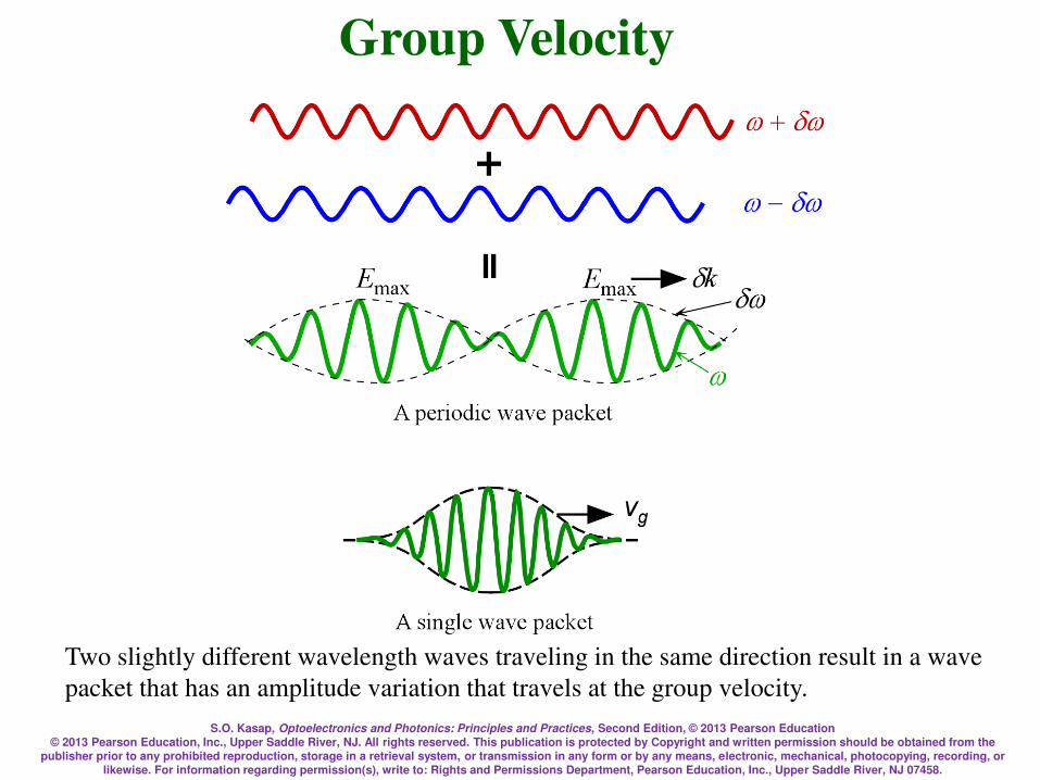
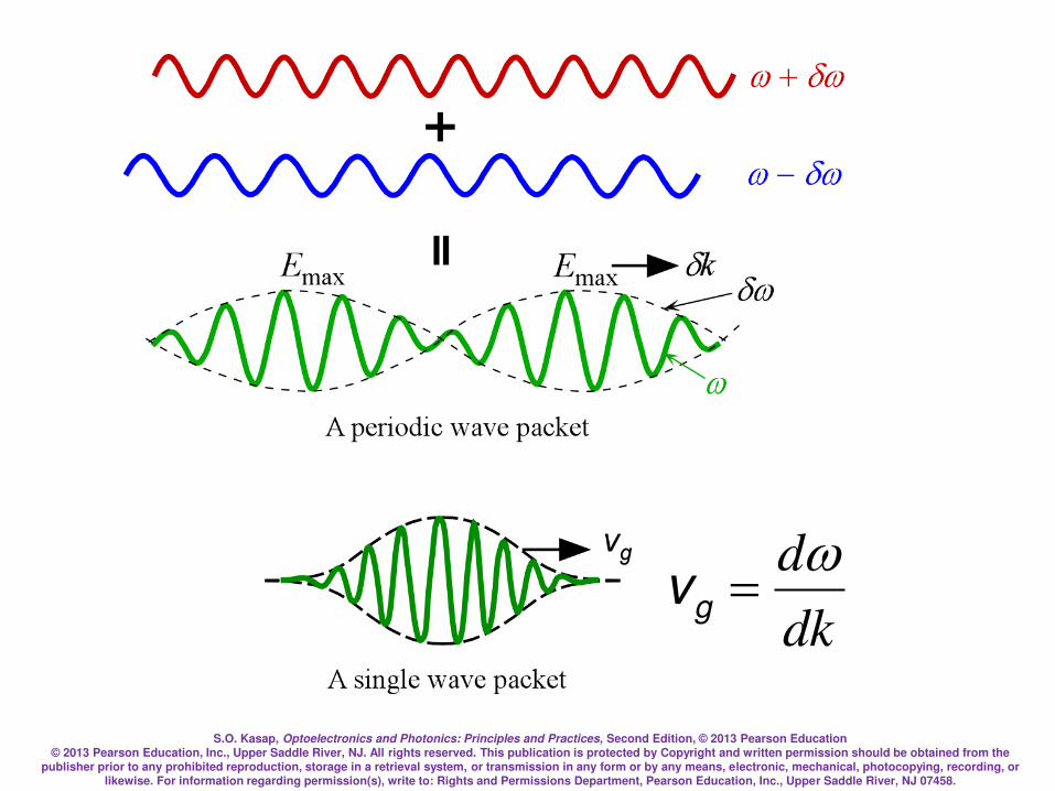
Two slightly different wavelength waves traveling in the same direction result in a wave
packet that has an amplitude variation that travels at the group velocity.
Group Velocity
S.O. Kasap, Optoelectronics and Photonics: Principles and Practices, Second Edition, © 2013 Pearson Education © 2013 Pearson Education, Inc., Upper Saddle River, NJ. All rights reserved. This publication is protected by Copyright and written permission should be obtained from the
publisher prior to any prohibited reproduction, storage in a retrieval system, or transmission in any form or by any means, electronic, mechanical, photocopying, recording, or likewise. For information regarding permission(s), write to: Rights and Permissions Department, Pearson Education, Inc., Upper Saddle River, NJ 07458.
dk
d=gv
S.O. Kasap, Optoelectronics and Photonics: Principles and Practices, Second Edition, © 2013 Pearson Education © 2013 Pearson Education, Inc., Upper Saddle River, NJ. All rights reserved. This publication is protected by Copyright and written permission should be obtained from the
publisher prior to any prohibited reproduction, storage in a retrieval system, or transmission in any form or by any means, electronic, mechanical, photocopying, recording, or likewise. For information regarding permission(s), write to: Rights and Permissions Department, Pearson Education, Inc., Upper Saddle River, NJ 07458.
Group Velocity
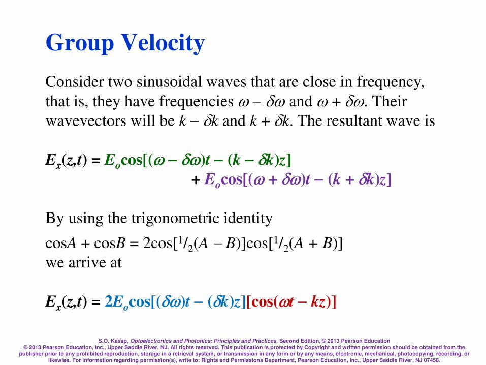
Consider two sinusoidal waves that are close in frequency,
that is, they have frequencies and + . Their
wavevectors will be kk and k + k. The resultant wave is
Ex(z,t) = Eocos[()t(kk)z]
+ Eocos[( + )t(k + k)z]
By using the trigonometric identity
cosA + cosB = 2cos[1/2(AB)]cos[1/2(A + B)]
we arrive at
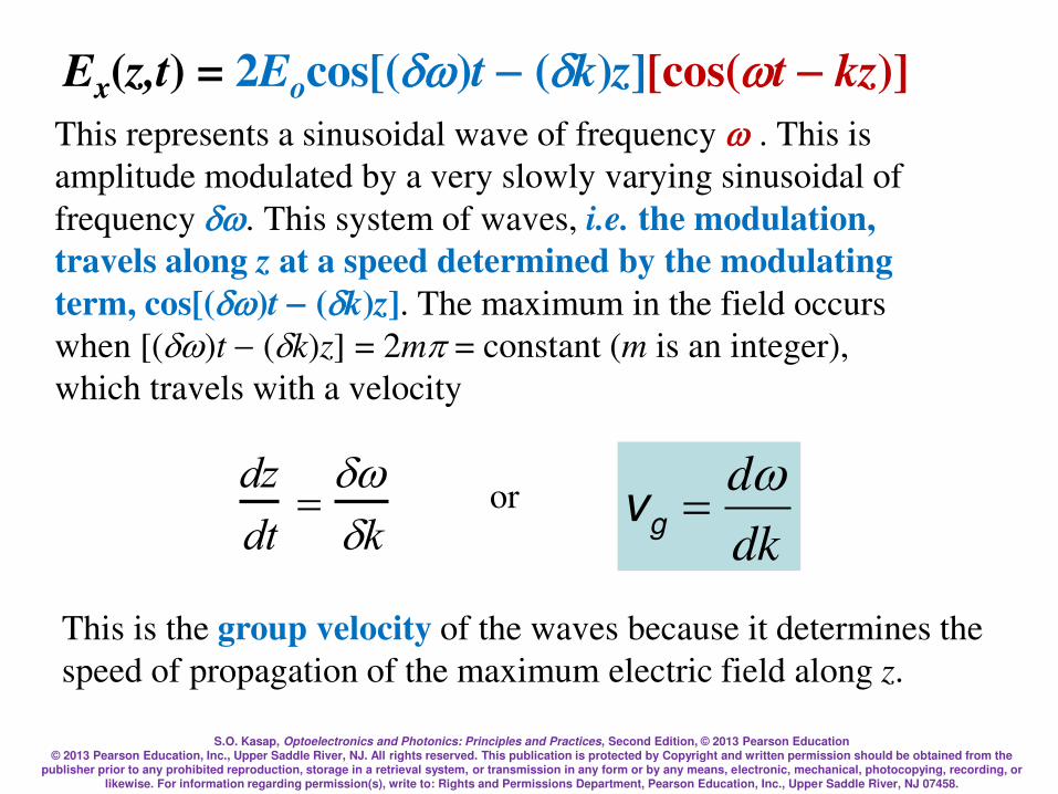
Ex(z,t) = 2Eocos[()t(k)z][cos(tkz)]
S.O. Kasap, Optoelectronics and Photonics: Principles and Practices, Second Edition, © 2013 Pearson Education © 2013 Pearson Education, Inc., Upper Saddle River, NJ. All rights reserved. This publication is protected by Copyright and written permission should be obtained from the
publisher prior to any prohibited reproduction, storage in a retrieval system, or transmission in any form or by any means, electronic, mechanical, photocopying, recording, or likewise. For information regarding permission(s), write to: Rights and Permissions Department, Pearson Education, Inc., Upper Saddle River, NJ 07458.
This represents a sinusoidal wave of frequency . This is
amplitude modulated by a very slowly varying sinusoidal of
frequency . This system of waves, i.e. the modulation,
travels along z at a speed determined by the modulating
term, cos[()t(k)z]. The maximum in the field occurs
when [()t(k)z] = 2m = constant (m is an integer),
which travels with a velocity
dz
dt=k
or
dk
d=gv
This is the group velocity of the waves because it determines the
speed of propagation of the maximum electric field along z.
Ex(z,t) = 2Eocos[()t(k)z][cos(tkz)]
S.O. Kasap, Optoelectronics and Photonics: Principles and Practices, Second Edition, © 2013 Pearson Education © 2013 Pearson Education, Inc., Upper Saddle River, NJ. All rights reserved. This publication is protected by Copyright and written permission should be obtained from the
publisher prior to any prohibited reproduction, storage in a retrieval system, or transmission in any form or by any means, electronic, mechanical, photocopying, recording, or likewise. For information regarding permission(s), write to: Rights and Permissions Department, Pearson Education, Inc., Upper Saddle River, NJ 07458.
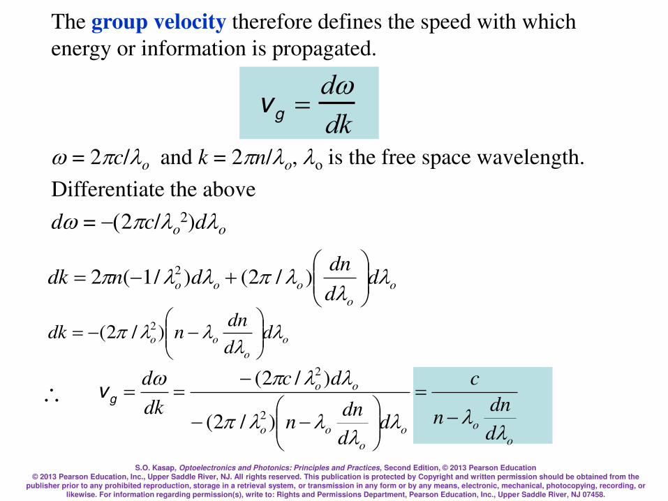
The group velocity therefore defines the speed with which
energy or information is propagated.
= 2c/o and k = 2n/o, o is the free space wavelength.
Differentiate the above
d = (2c/o2)do
o
o
ooo dd
dndndk
= )/2()/1(2 2
vg =
ddk
o
o
oo dd
dnndk
= )/2( 2
o
oo
o
oo
oo
d
dnn
c
dd
dnn
dc
dk
d
=
==
)/2(
)/2(
2
2
gv

S.O. Kasap, Optoelectronics and Photonics: Principles and Practices, Second Edition, © 2013 Pearson Education © 2013 Pearson Education, Inc., Upper Saddle River, NJ. All rights reserved. This publication is protected by Copyright and written permission should be obtained from the
publisher prior to any prohibited reproduction, storage in a retrieval system, or transmission in any form or by any means, electronic, mechanical, photocopying, recording, or likewise. For information regarding permission(s), write to: Rights and Permissions Department, Pearson Education, Inc., Upper Saddle River, NJ 07458.
where n = n() is a function of the wavelength. The group
velocity vg in a medium is given by,
vg(medium) =ddk
=c
n dn
d
This can be written as
vg(medium) =c
Ng
Group Velocity and Group Index
S.O. Kasap, Optoelectronics and Photonics: Principles and Practices, Second Edition, © 2013 Pearson Education © 2013 Pearson Education, Inc., Upper Saddle River, NJ. All rights reserved. This publication is protected by Copyright and written permission should be obtained from the
publisher prior to any prohibited reproduction, storage in a retrieval system, or transmission in any form or by any means, electronic, mechanical, photocopying, recording, or likewise. For information regarding permission(s), write to: Rights and Permissions Department, Pearson Education, Inc., Upper Saddle River, NJ 07458.
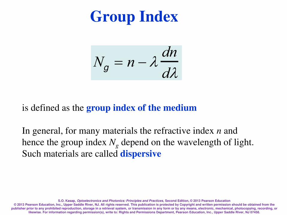
Ng = n
dn
d
is defined as the group index of the medium
In general, for many materials the refractive index n and
hence the group index Ng depend on the wavelength of light.
Such materials are called dispersive
Group Index

S.O. Kasap, Optoelectronics and Photonics: Principles and Practices, Second Edition, © 2013 Pearson Education © 2013 Pearson Education, Inc., Upper Saddle River, NJ. All rights reserved. This publication is protected by Copyright and written permission should be obtained from the
publisher prior to any prohibited reproduction, storage in a retrieval system, or transmission in any form or by any means, electronic, mechanical, photocopying, recording, or likewise. For information regarding permission(s), write to: Rights and Permissions Department, Pearson Education, Inc., Upper Saddle River, NJ 07458.
Refractive index n and the group index Ng of pure SiO2 (silica) glass as a function of
wavelength.
Refractive Index and Group Index
S.O. Kasap, Optoelectronics and Photonics: Principles and Practices, Second Edition, © 2013 Pearson Education © 2013 Pearson Education, Inc., Upper Saddle River, NJ. All rights reserved. This publication is protected by Copyright and written permission should be obtained from the
publisher prior to any prohibited reproduction, storage in a retrieval system, or transmission in any form or by any means, electronic, mechanical, photocopying, recording, or likewise. For information regarding permission(s), write to: Rights and Permissions Department, Pearson Education, Inc., Upper Saddle River, NJ 07458.
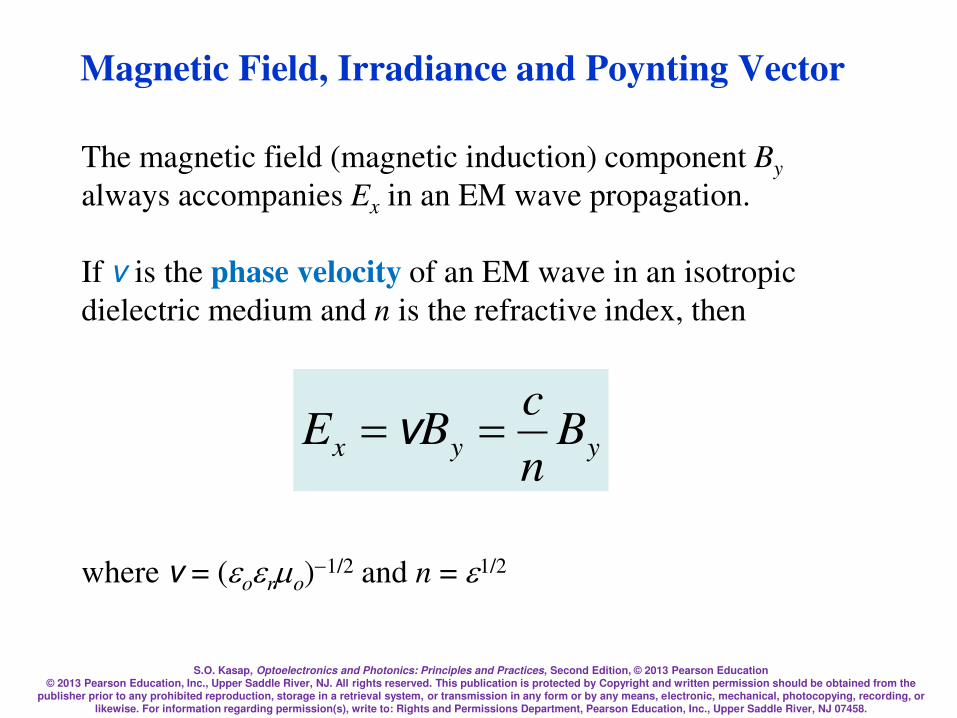
Magnetic Field, Irradiance and Poynting Vector
The magnetic field (magnetic induction) component By
always accompanies Ex in an EM wave propagation.
If v is the phase velocity of an EM wave in an isotropic
dielectric medium and n is the refractive index, then
yyx Bn
cBE == v
where v = (oro)1/2 and n = 1/2
S.O. Kasap, Optoelectronics and Photonics: Principles and Practices, Second Edition, © 2013 Pearson Education © 2013 Pearson Education, Inc., Upper Saddle River, NJ. All rights reserved. This publication is protected by Copyright and written permission should be obtained from the
publisher prior to any prohibited reproduction, storage in a retrieval system, or transmission in any form or by any means, electronic, mechanical, photocopying, recording, or likewise. For information regarding permission(s), write to: Rights and Permissions Department, Pearson Education, Inc., Upper Saddle River, NJ 07458.
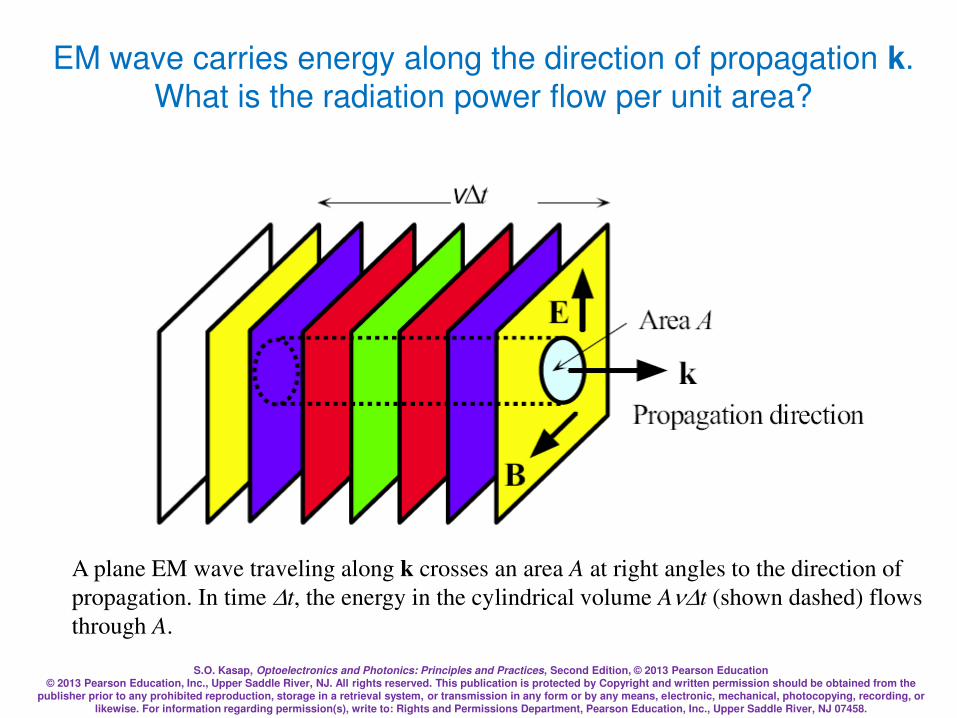
A plane EM wave traveling along k crosses an area A at right angles to the direction of
propagation. In time t, the energy in the cylindrical volume At (shown dashed) flows
through A.
EM wave carries energy along the direction of propagation k.
What is the radiation power flow per unit area?
S.O. Kasap, Optoelectronics and Photonics: Principles and Practices, Second Edition, © 2013 Pearson Education © 2013 Pearson Education, Inc., Upper Saddle River, NJ. All rights reserved. This publication is protected by Copyright and written permission should be obtained from the
publisher prior to any prohibited reproduction, storage in a retrieval system, or transmission in any form or by any means, electronic, mechanical, photocopying, recording, or likewise. For information regarding permission(s), write to: Rights and Permissions Department, Pearson Education, Inc., Upper Saddle River, NJ 07458.
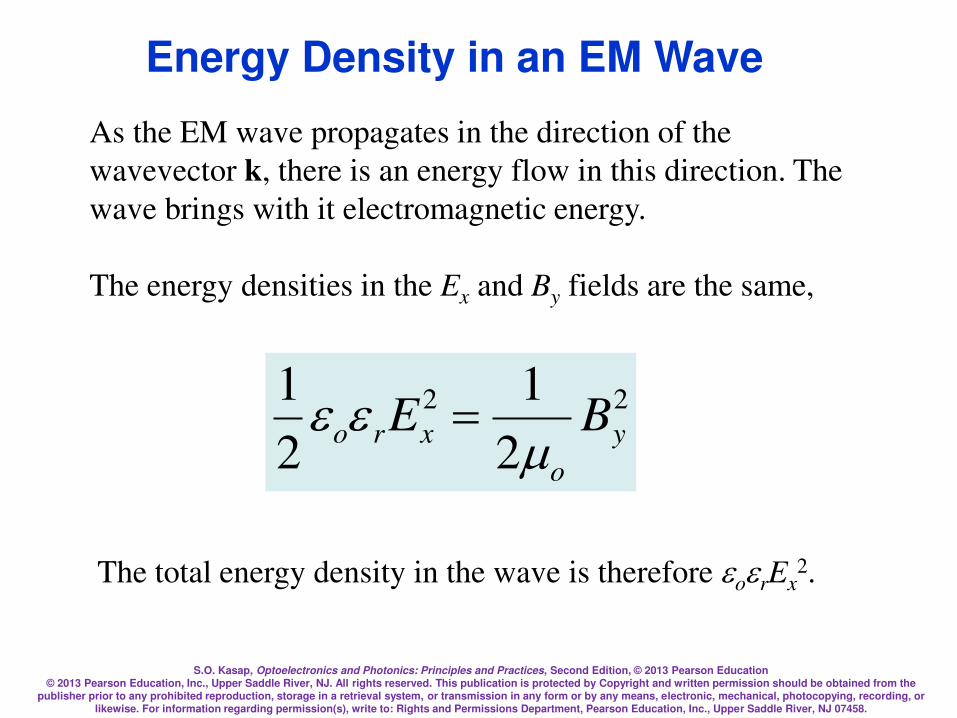
As the EM wave propagates in the direction of the
wavevector k, there is an energy flow in this direction. The
wave brings with it electromagnetic energy.
The energy densities in the Ex and By fields are the same,
22
2
1
2
1y
o
xro BE
=
The total energy density in the wave is therefore orEx2.
Energy Density in an EM Wave

S.O. Kasap, Optoelectronics and Photonics: Principles and Practices, Second Edition, © 2013 Pearson Education © 2013 Pearson Education, Inc., Upper Saddle River, NJ. All rights reserved. This publication is protected by Copyright and written permission should be obtained from the
publisher prior to any prohibited reproduction, storage in a retrieval system, or transmission in any form or by any means, electronic, mechanical, photocopying, recording, or likewise. For information regarding permission(s), write to: Rights and Permissions Department, Pearson Education, Inc., Upper Saddle River, NJ 07458.
If S is the EM power flow per unit area,
S = Energy flow per unit time per unit area
yxroxroxro BEE
tA
EtAS 22
2))((vv
v==
=
In an isotropic medium, the energy flow is in the direction of
wave propagation. If we use the vectors E and B to represent
the electric and magnetic fields in the EM wave, then the EM
power flow per unit area can be written as
Poynting Vector and EM Power Flow
S = v2orEB

S.O. Kasap, Optoelectronics and Photonics: Principles and Practices, Second Edition, © 2013 Pearson Education © 2013 Pearson Education, Inc., Upper Saddle River, NJ. All rights reserved. This publication is protected by Copyright and written permission should be obtained from the
publisher prior to any prohibited reproduction, storage in a retrieval system, or transmission in any form or by any means, electronic, mechanical, photocopying, recording, or likewise. For information regarding permission(s), write to: Rights and Permissions Department, Pearson Education, Inc., Upper Saddle River, NJ 07458.
where S, called the Poynting vector, represents the energy
flow per unit time per unit area in a direction determined by
EB (direction of propagation). Its magnitude, power flow
per unit area, is called the irradiance (instantaneous
irradiance, or intensity).
The average irradiance is
2
21
average oro ESI v==
Poynting Vector and Intensity
S.O. Kasap, Optoelectronics and Photonics: Principles and Practices, Second Edition, © 2013 Pearson Education © 2013 Pearson Education, Inc., Upper Saddle River, NJ. All rights reserved. This publication is protected by Copyright and written permission should be obtained from the
publisher prior to any prohibited reproduction, storage in a retrieval system, or transmission in any form or by any means, electronic, mechanical, photocopying, recording, or likewise. For information regarding permission(s), write to: Rights and Permissions Department, Pearson Education, Inc., Upper Saddle River, NJ 07458.
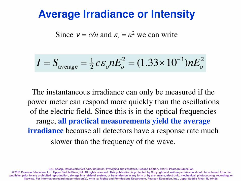
Since v = c/n and r = n2 we can write
232
21
average )1033.1( ooo nEnEcSI===
The instantaneous irradiance can only be measured if the
power meter can respond more quickly than the oscillations
of the electric field. Since this is in the optical frequencies
range, all practical measurements yield the average
irradiance because all detectors have a response rate much
slower than the frequency of the wave.
Average Irradiance or Intensity
S.O. Kasap, Optoelectronics and Photonics: Principles and Practices, Second Edition, © 2013 Pearson Education © 2013 Pearson Education, Inc., Upper Saddle River, NJ. All rights reserved. This publication is protected by Copyright and written permission should be obtained from the
publisher prior to any prohibited reproduction, storage in a retrieval system, or transmission in any form or by any means, electronic, mechanical, photocopying, recording, or likewise. For information regarding permission(s), write to: Rights and Permissions Department, Pearson Education, Inc., Upper Saddle River, NJ 07458.
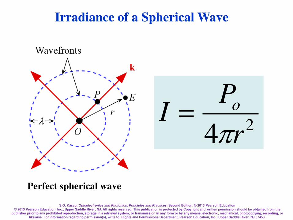
Irradiance of a Spherical Wave
24 r
PI o
=
Perfect spherical wave

S.O. Kasap, Optoelectronics and Photonics: Principles and Practices, Second Edition, © 2013 Pearson Education © 2013 Pearson Education, Inc., Upper Saddle River, NJ. All rights reserved. This publication is protected by Copyright and written permission should be obtained from the
publisher prior to any prohibited reproduction, storage in a retrieval system, or transmission in any form or by any means, electronic, mechanical, photocopying, recording, or likewise. For information regarding permission(s), write to: Rights and Permissions Department, Pearson Education, Inc., Upper Saddle River, NJ 07458.
Spherical wave front
9A4AAA
r
2r
3r
O
Source
Po
Irradiance of a Spherical Wave
24 r
PI o
=
S.O. Kasap, Optoelectronics and Photonics: Principles and Practices, Second Edition, © 2013 Pearson Education © 2013 Pearson Education, Inc., Upper Saddle River, NJ. All rights reserved. This publication is protected by Copyright and written permission should be obtained from the
publisher prior to any prohibited reproduction, storage in a retrieval system, or transmission in any form or by any means, electronic, mechanical, photocopying, recording, or likewise. For information regarding permission(s), write to: Rights and Permissions Department, Pearson Education, Inc., Upper Saddle River, NJ 07458.
A Gaussian Beam
I(r,z) = [2P/(w2)]exp(2r2/w2)
qo= w/z = /(wo) 2qo = Far field divergence
S.O. Kasap, Optoelectronics and Photonics: Principles and Practices, Second Edition, © 2013 Pearson Education © 2013 Pearson Education, Inc., Upper Saddle River, NJ. All rights reserved. This publication is protected by Copyright and written permission should be obtained from the
publisher prior to any prohibited reproduction, storage in a retrieval system, or transmission in any form or by any means, electronic, mechanical, photocopying, recording, or likewise. For information regarding permission(s), write to: Rights and Permissions Department, Pearson Education, Inc., Upper Saddle River, NJ 07458.
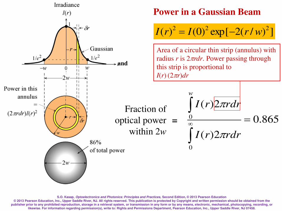
Power in a Gaussian Beam
])/(2exp[)0()( 222wrIrI =
865.0
2)(
2)(
0
0 =
rdrrI
rdrrI
w
Fraction of
optical power
within 2w
=
Area of a circular thin strip (annulus) with
radius r is 2rdr. Power passing through
this strip is proportional to
I(r) (2r)dr
and

S.O. Kasap, Optoelectronics and Photonics: Principles and Practices, Second Edition, © 2013 Pearson Education © 2013 Pearson Education, Inc., Upper Saddle River, NJ. All rights reserved. This publication is protected by Copyright and written permission should be obtained from the
publisher prior to any prohibited reproduction, storage in a retrieval system, or transmission in any form or by any means, electronic, mechanical, photocopying, recording, or likewise. For information regarding permission(s), write to: Rights and Permissions Department, Pearson Education, Inc., Upper Saddle River, NJ 07458.
Snell’s Law or Descartes’s Law?
S.O. Kasap, Optoelectronics and Photonics: Principles and Practices, Second Edition, © 2013 Pearson Education © 2013 Pearson Education, Inc., Upper Saddle River, NJ. All rights reserved. This publication is protected by Copyright and written permission should be obtained from the
publisher prior to any prohibited reproduction, storage in a retrieval system, or transmission in any form or by any means, electronic, mechanical, photocopying, recording, or likewise. For information regarding permission(s), write to: Rights and Permissions Department, Pearson Education, Inc., Upper Saddle River, NJ 07458.
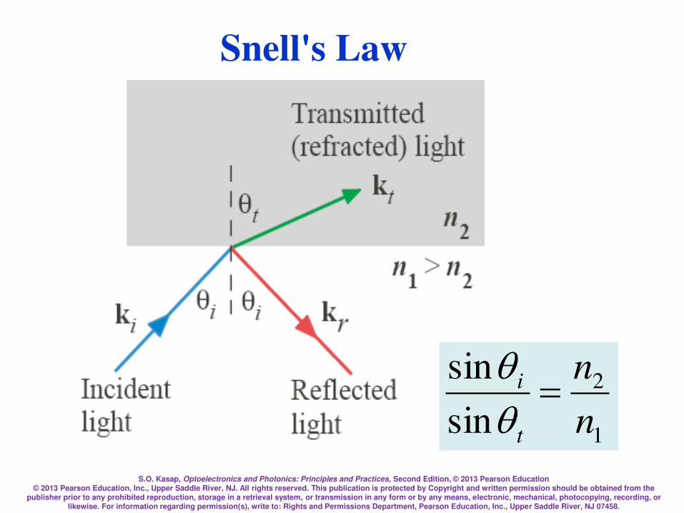
Snell's Law
1
2
sin
sin
n
n
t
i =qq
S.O. Kasap, Optoelectronics and Photonics: Principles and Practices, Second Edition, © 2013 Pearson Education © 2013 Pearson Education, Inc., Upper Saddle River, NJ. All rights reserved. This publication is protected by Copyright and written permission should be obtained from the
publisher prior to any prohibited reproduction, storage in a retrieval system, or transmission in any form or by any means, electronic, mechanical, photocopying, recording, or likewise. For information regarding permission(s), write to: Rights and Permissions Department, Pearson Education, Inc., Upper Saddle River, NJ 07458.
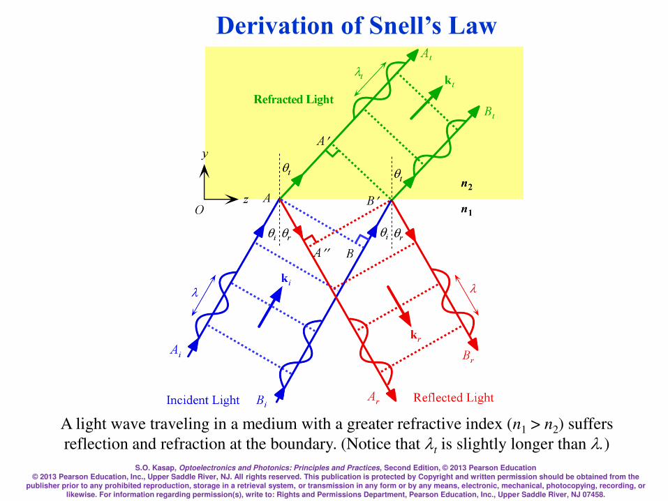
A light wave traveling in a medium with a greater refractive index (n1 > n2) suffers
reflection and refraction at the boundary. (Notice that t is slightly longer than .)
Derivation of Snell’s Law
S.O. Kasap, Optoelectronics and Photonics: Principles and Practices, Second Edition, © 2013 Pearson Education © 2013 Pearson Education, Inc., Upper Saddle River, NJ. All rights reserved. This publication is protected by Copyright and written permission should be obtained from the
publisher prior to any prohibited reproduction, storage in a retrieval system, or transmission in any form or by any means, electronic, mechanical, photocopying, recording, or likewise. For information regarding permission(s), write to: Rights and Permissions Department, Pearson Education, Inc., Upper Saddle River, NJ 07458.
We can use constructive interference to show that there can
only be one reflected wave which occurs at an angle equal to
the incidence angle. The two waves along Ai and Bi are in
phase.
When these waves are reflected to become waves Ar and Br
then they must still be in phase, otherwise they will interfere
destructively and destroy each other. The only way the two
waves can stay in phase is if qr = qi. All other angles lead to
the waves Ar and Br being out of phase and interfering
destructively.
Snell’s Law
S.O. Kasap, Optoelectronics and Photonics: Principles and Practices, Second Edition, © 2013 Pearson Education © 2013 Pearson Education, Inc., Upper Saddle River, NJ. All rights reserved. This publication is protected by Copyright and written permission should be obtained from the
publisher prior to any prohibited reproduction, storage in a retrieval system, or transmission in any form or by any means, electronic, mechanical, photocopying, recording, or likewise. For information regarding permission(s), write to: Rights and Permissions Department, Pearson Education, Inc., Upper Saddle River, NJ 07458.
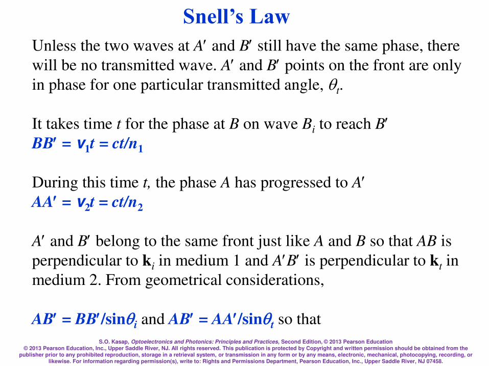
Unless the two waves at A and B still have the same phase, there
will be no transmitted wave. A and B points on the front are only
in phase for one particular transmitted angle, qt.
It takes time t for the phase at B on wave Bi to reach B BB = v1t = ct/n1
During this time t, the phase A has progressed to A AA = v2t = ct/n2
A and B belong to the same front just like A and B so that AB is
perpendicular to ki in medium 1 and AB is perpendicular to kt in
medium 2. From geometrical considerations,
AB = BB/sinqi and AB = AA/sinqt so that
Snell’s Law
S.O. Kasap, Optoelectronics and Photonics: Principles and Practices, Second Edition, © 2013 Pearson Education © 2013 Pearson Education, Inc., Upper Saddle River, NJ. All rights reserved. This publication is protected by Copyright and written permission should be obtained from the
publisher prior to any prohibited reproduction, storage in a retrieval system, or transmission in any form or by any means, electronic, mechanical, photocopying, recording, or likewise. For information regarding permission(s), write to: Rights and Permissions Department, Pearson Education, Inc., Upper Saddle River, NJ 07458.
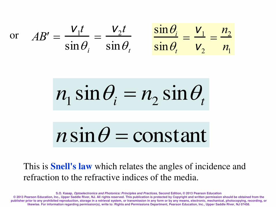
or A B =
v1t
sinq i
=v2t
sinq t
sinqi
sinqt
=v1
v2
=n2
n1
This is Snell's law which relates the angles of incidence and
refraction to the refractive indices of the media.
ti nn qq sinsin 21 =
constantsin =qn

S.O. Kasap, Optoelectronics and Photonics: Principles and Practices, Second Edition, © 2013 Pearson Education © 2013 Pearson Education, Inc., Upper Saddle River, NJ. All rights reserved. This publication is protected by Copyright and written permission should be obtained from the
publisher prior to any prohibited reproduction, storage in a retrieval system, or transmission in any form or by any means, electronic, mechanical, photocopying, recording, or likewise. For information regarding permission(s), write to: Rights and Permissions Department, Pearson Education, Inc., Upper Saddle River, NJ 07458.
When n1 > n2 then obviously the transmitted angle is greater
than the incidence angle as apparent in the figure. When the
refraction angle qt reaches 90°, the incidence angle is called
the critical angle qc which is given by
ti nn qq sinsin 21 =
1
2sinn
nc =q
S.O. Kasap, Optoelectronics and Photonics: Principles and Practices, Second Edition, © 2013 Pearson Education © 2013 Pearson Education, Inc., Upper Saddle River, NJ. All rights reserved. This publication is protected by Copyright and written permission should be obtained from the
publisher prior to any prohibited reproduction, storage in a retrieval system, or transmission in any form or by any means, electronic, mechanical, photocopying, recording, or likewise. For information regarding permission(s), write to: Rights and Permissions Department, Pearson Education, Inc., Upper Saddle River, NJ 07458.
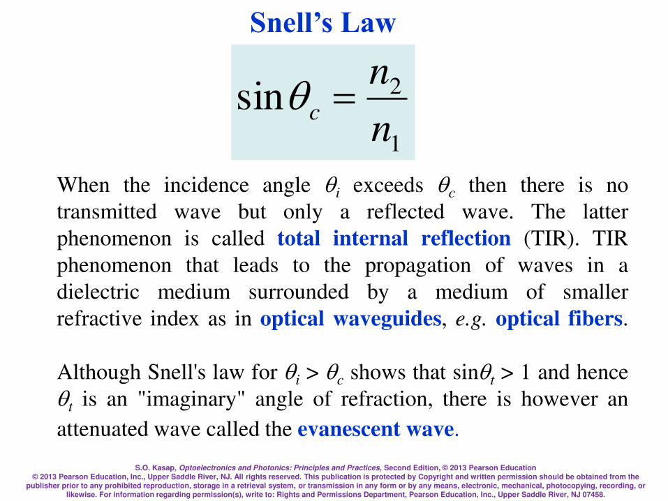
When the incidence angle qi exceeds qc then there is no
transmitted wave but only a reflected wave. The latter
phenomenon is called total internal reflection (TIR). TIR
phenomenon that leads to the propagation of waves in a
dielectric medium surrounded by a medium of smaller
refractive index as in optical waveguides, e.g. optical fibers.
Although Snell's law for qi > qc shows that sinqt > 1 and hence
qt is an "imaginary" angle of refraction, there is however an
attenuated wave called the evanescent wave.
1
2sinn
nc =q
Snell’s Law

S.O. Kasap, Optoelectronics and Photonics: Principles and Practices, Second Edition, © 2013 Pearson Education © 2013 Pearson Education, Inc., Upper Saddle River, NJ. All rights reserved. This publication is protected by Copyright and written permission should be obtained from the
publisher prior to any prohibited reproduction, storage in a retrieval system, or transmission in any form or by any means, electronic, mechanical, photocopying, recording, or likewise. For information regarding permission(s), write to: Rights and Permissions Department, Pearson Education, Inc., Upper Saddle River, NJ 07458.
Light wave traveling in a more dense medium strikes a less dense medium.
Depending on the incidence angle with respect to qc, which is determined by the
ratio of the refractive indices, the wave may be transmitted (refracted) or reflected.
(a) qi < qc (b) qi = qc (c) qi > qc and total internal reflection (TIR).
Total Internal Reflection
S.O. Kasap, Optoelectronics and Photonics: Principles and Practices, Second Edition, © 2013 Pearson Education © 2013 Pearson Education, Inc., Upper Saddle River, NJ. All rights reserved. This publication is protected by Copyright and written permission should be obtained from the
publisher prior to any prohibited reproduction, storage in a retrieval system, or transmission in any form or by any means, electronic, mechanical, photocopying, recording, or likewise. For information regarding permission(s), write to: Rights and Permissions Department, Pearson Education, Inc., Upper Saddle River, NJ 07458.
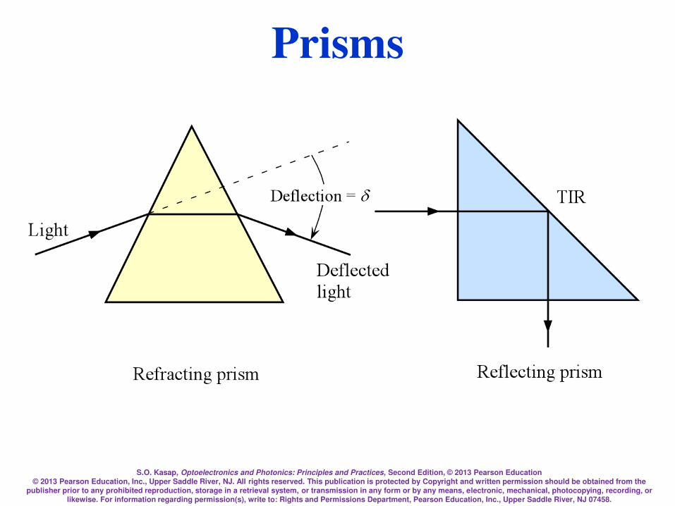
Prisms
S.O. Kasap, Optoelectronics and Photonics: Principles and Practices, Second Edition, © 2013 Pearson Education © 2013 Pearson Education, Inc., Upper Saddle River, NJ. All rights reserved. This publication is protected by Copyright and written permission should be obtained from the
publisher prior to any prohibited reproduction, storage in a retrieval system, or transmission in any form or by any means, electronic, mechanical, photocopying, recording, or likewise. For information regarding permission(s), write to: Rights and Permissions Department, Pearson Education, Inc., Upper Saddle River, NJ 07458.
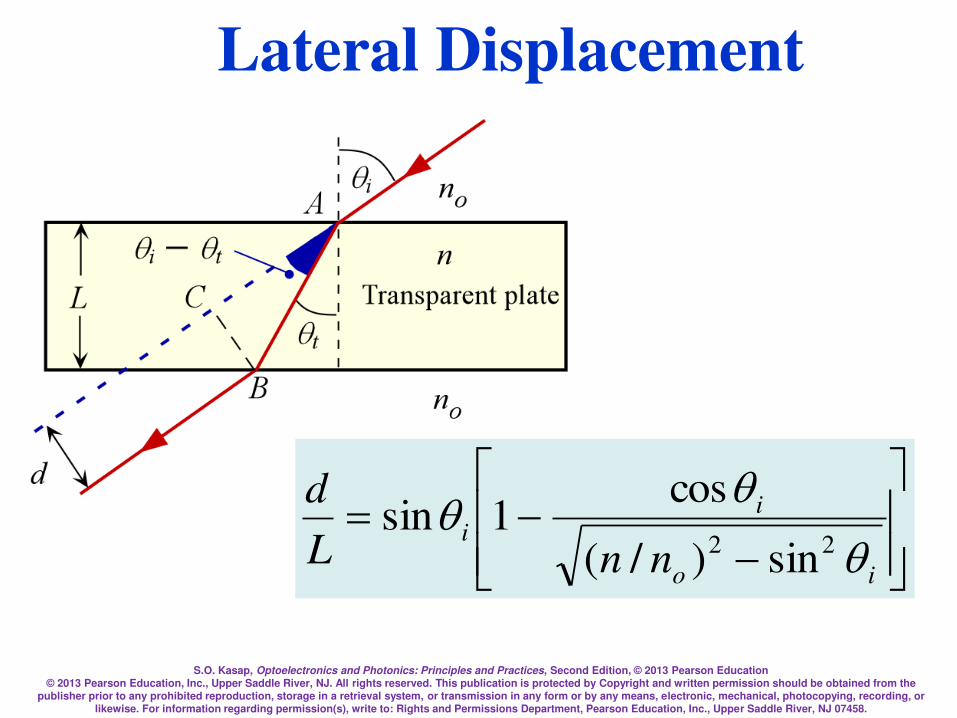
=
io
ii
nnL
d
q
qq22 sin)/(
cos1sin
Lateral Displacement

S.O. Kasap, Optoelectronics and Photonics: Principles and Practices, Second Edition, © 2013 Pearson Education © 2013 Pearson Education, Inc., Upper Saddle River, NJ. All rights reserved. This publication is protected by Copyright and written permission should be obtained from the
publisher prior to any prohibited reproduction, storage in a retrieval system, or transmission in any form or by any means, electronic, mechanical, photocopying, recording, or likewise. For information regarding permission(s), write to: Rights and Permissions Department, Pearson Education, Inc., Upper Saddle River, NJ 07458.
Lateral Displacement
S.O. Kasap, Optoelectronics and Photonics: Principles and Practices, Second Edition, © 2013 Pearson Education © 2013 Pearson Education, Inc., Upper Saddle River, NJ. All rights reserved. This publication is protected by Copyright and written permission should be obtained from the
publisher prior to any prohibited reproduction, storage in a retrieval system, or transmission in any form or by any means, electronic, mechanical, photocopying, recording, or likewise. For information regarding permission(s), write to: Rights and Permissions Department, Pearson Education, Inc., Upper Saddle River, NJ 07458.
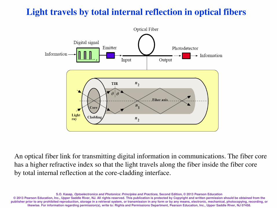
Light travels by total internal reflection in optical fibers
An optical fiber link for transmitting digital information in communications. The fiber core
has a higher refractive index so that the light travels along the fiber inside the fiber core
by total internal reflection at the core-cladding interface.
S.O. Kasap, Optoelectronics and Photonics: Principles and Practices, Second Edition, © 2013 Pearson Education © 2013 Pearson Education, Inc., Upper Saddle River, NJ. All rights reserved. This publication is protected by Copyright and written permission should be obtained from the
publisher prior to any prohibited reproduction, storage in a retrieval system, or transmission in any form or by any means, electronic, mechanical, photocopying, recording, or likewise. For information regarding permission(s), write to: Rights and Permissions Department, Pearson Education, Inc., Upper Saddle River, NJ 07458.
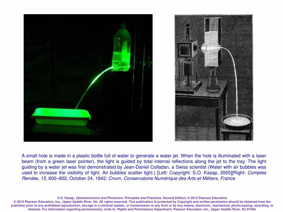
A small hole is made in a plastic bottle full of water to generate a water jet. When the hole is illuminated with a laser
beam (from a green laser pointer), the light is guided by total internal reflections along the jet to the tray. The light
guiding by a water jet was first demonstrated by Jean-Daniel Colladan, a Swiss scientist (Water with air bubbles was
used to increase the visibility of light. Air bubbles scatter light.) [Left: Copyright: S.O. Kasap, 2005][Right: Comptes
Rendes, 15, 800–802, October 24, 1842; Cnum, Conservatoire Numérique des Arts et Métiers, France
S.O. Kasap, Optoelectronics and Photonics: Principles and Practices, Second Edition, © 2013 Pearson Education © 2013 Pearson Education, Inc., Upper Saddle River, NJ. All rights reserved. This publication is protected by Copyright and written permission should be obtained from the
publisher prior to any prohibited reproduction, storage in a retrieval system, or transmission in any form or by any means, electronic, mechanical, photocopying, recording, or likewise. For information regarding permission(s), write to: Rights and Permissions Department, Pearson Education, Inc., Upper Saddle River, NJ 07458.
Fresnel's Equations
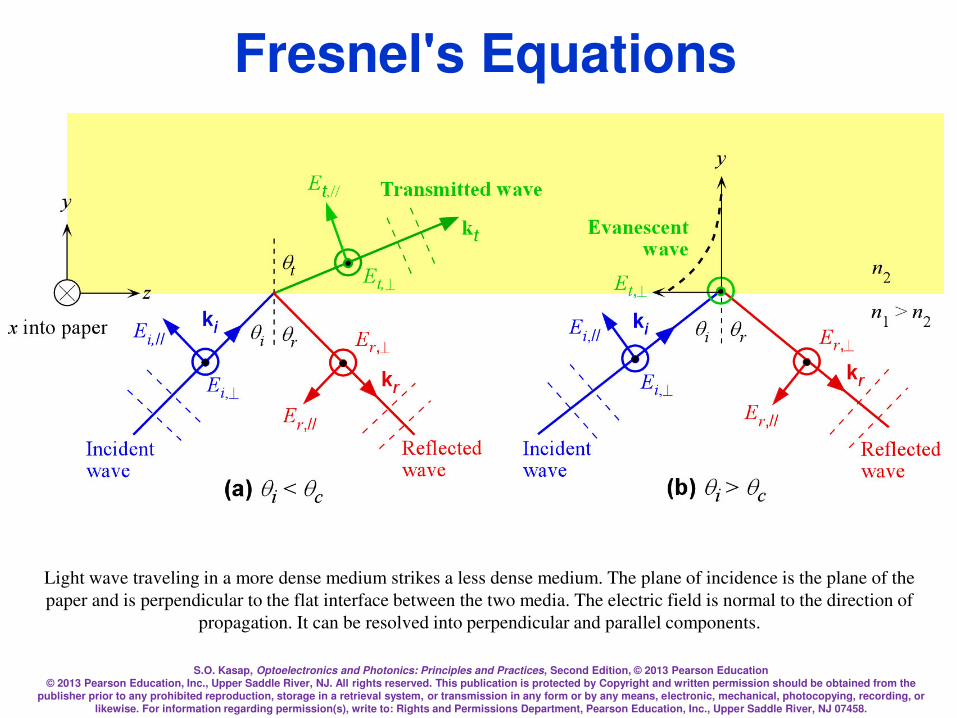
Light wave traveling in a more dense medium strikes a less dense medium. The plane of incidence is the plane of the
paper and is perpendicular to the flat interface between the two media. The electric field is normal to the direction of
propagation. It can be resolved into perpendicular and parallel components.
S.O. Kasap, Optoelectronics and Photonics: Principles and Practices, Second Edition, © 2013 Pearson Education © 2013 Pearson Education, Inc., Upper Saddle River, NJ. All rights reserved. This publication is protected by Copyright and written permission should be obtained from the
publisher prior to any prohibited reproduction, storage in a retrieval system, or transmission in any form or by any means, electronic, mechanical, photocopying, recording, or likewise. For information regarding permission(s), write to: Rights and Permissions Department, Pearson Education, Inc., Upper Saddle River, NJ 07458.
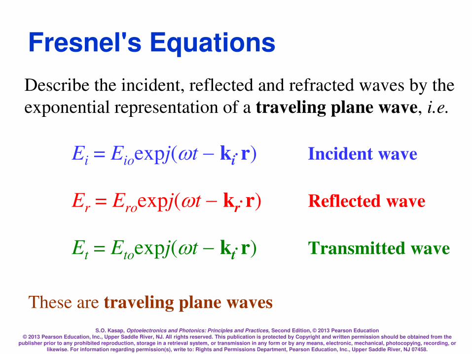
Describe the incident, reflected and refracted waves by the
exponential representation of a traveling plane wave, i.e.
Ei = Eioexpj(tkir) Incident wave
Er = Eroexpj(tkrr) Reflected wave
Et = Etoexpj(tktr) Transmitted wave
Fresnel's Equations
These are traveling plane waves
S.O. Kasap, Optoelectronics and Photonics: Principles and Practices, Second Edition, © 2013 Pearson Education © 2013 Pearson Education, Inc., Upper Saddle River, NJ. All rights reserved. This publication is protected by Copyright and written permission should be obtained from the
publisher prior to any prohibited reproduction, storage in a retrieval system, or transmission in any form or by any means, electronic, mechanical, photocopying, recording, or likewise. For information regarding permission(s), write to: Rights and Permissions Department, Pearson Education, Inc., Upper Saddle River, NJ 07458.
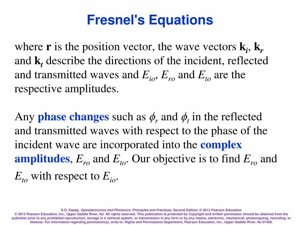
where r is the position vector, the wave vectors ki, kr
and kt describe the directions of the incident, reflected
and transmitted waves and Eio, Ero and Eto are the
respective amplitudes.
Any phase changes such as r and t in the reflected
and transmitted waves with respect to the phase of the
incident wave are incorporated into the complex
amplitudes, Ero and Eto. Our objective is to find Ero and
Eto with respect to Eio.
Fresnel's Equations

S.O. Kasap, Optoelectronics and Photonics: Principles and Practices, Second Edition, © 2013 Pearson Education © 2013 Pearson Education, Inc., Upper Saddle River, NJ. All rights reserved. This publication is protected by Copyright and written permission should be obtained from the
publisher prior to any prohibited reproduction, storage in a retrieval system, or transmission in any form or by any means, electronic, mechanical, photocopying, recording, or likewise. For information regarding permission(s), write to: Rights and Permissions Department, Pearson Education, Inc., Upper Saddle River, NJ 07458.
The electric and magnetic fields anywhere on the wave must
be perpendicular to each other as a requirement of
electromagnetic wave theory. This means that with E// in the
EM wave we have a magnetic field B associated with it such
that, B=(n/c)E//. Similarly E will have a magnetic field B//
associated with it such that B//=(n/c)E.
We use boundary conditions
Etangential(1) = Etangential(2)
Fresnel's Equations
S.O. Kasap, Optoelectronics and Photonics: Principles and Practices, Second Edition, © 2013 Pearson Education © 2013 Pearson Education, Inc., Upper Saddle River, NJ. All rights reserved. This publication is protected by Copyright and written permission should be obtained from the
publisher prior to any prohibited reproduction, storage in a retrieval system, or transmission in any form or by any means, electronic, mechanical, photocopying, recording, or likewise. For information regarding permission(s), write to: Rights and Permissions Department, Pearson Education, Inc., Upper Saddle River, NJ 07458.
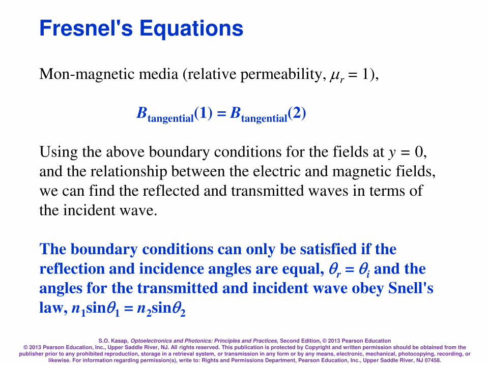
Mon-magnetic media (relative permeability, r = 1),
Btangential(1) = Btangential(2)
Using the above boundary conditions for the fields at y = 0,
and the relationship between the electric and magnetic fields,
we can find the reflected and transmitted waves in terms of
the incident wave.
The boundary conditions can only be satisfied if the
reflection and incidence angles are equal, qr = qi and the
angles for the transmitted and incident wave obey Snell's
law, n1sinq1 = n2sinq2
Fresnel's Equations

S.O. Kasap, Optoelectronics and Photonics: Principles and Practices, Second Edition, © 2013 Pearson Education © 2013 Pearson Education, Inc., Upper Saddle River, NJ. All rights reserved. This publication is protected by Copyright and written permission should be obtained from the
publisher prior to any prohibited reproduction, storage in a retrieval system, or transmission in any form or by any means, electronic, mechanical, photocopying, recording, or likewise. For information regarding permission(s), write to: Rights and Permissions Department, Pearson Education, Inc., Upper Saddle River, NJ 07458.
Fresnel's Equations
Incident wave Ei = Eioexpj(tkir)
Reflected wave Er = Eroexpj(tkrr)
Transmitted wave Et = Etoexpj(tktr)
S.O. Kasap, Optoelectronics and Photonics: Principles and Practices, Second Edition, © 2013 Pearson Education © 2013 Pearson Education, Inc., Upper Saddle River, NJ. All rights reserved. This publication is protected by Copyright and written permission should be obtained from the
publisher prior to any prohibited reproduction, storage in a retrieval system, or transmission in any form or by any means, electronic, mechanical, photocopying, recording, or likewise. For information regarding permission(s), write to: Rights and Permissions Department, Pearson Education, Inc., Upper Saddle River, NJ 07458.
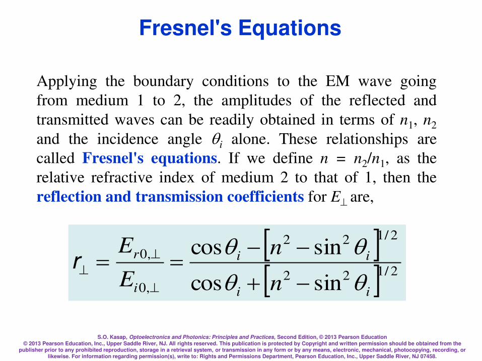
Applying the boundary conditions to the EM wave going
from medium 1 to 2, the amplitudes of the reflected and
transmitted waves can be readily obtained in terms of n1, n2
and the incidence angle qi alone. These relationships are
called Fresnel's equations. If we define n = n2/n1, as the
relative refractive index of medium 2 to that of 1, then the
reflection and transmission coefficients for Eare,
2/122
2/122
,0
,0
sincos
sincos
ii
ii
i
r
n
n
E
E
qqqq
==
r
Fresnel's Equations
S.O. Kasap, Optoelectronics and Photonics: Principles and Practices, Second Edition, © 2013 Pearson Education © 2013 Pearson Education, Inc., Upper Saddle River, NJ. All rights reserved. This publication is protected by Copyright and written permission should be obtained from the
publisher prior to any prohibited reproduction, storage in a retrieval system, or transmission in any form or by any means, electronic, mechanical, photocopying, recording, or likewise. For information regarding permission(s), write to: Rights and Permissions Department, Pearson Education, Inc., Upper Saddle River, NJ 07458.
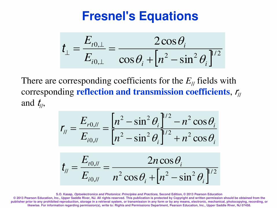
2/122,0
,0
sincos
cos2
ii
i
i
t
nE
E
qqq
==
t
There are corresponding coefficients for the E// fields with
corresponding reflection and transmission coefficients, r// and t//,
ii
ii
i
r
nn
nn
E
E
qqqq
cossin
cossin22/122
22/122
//,0
//,0
//
==r
2/1222//,0
//,0
//
sincos
cos2
ii
i
i
t
nn
n
E
E
qqq
==t
Fresnel's Equations
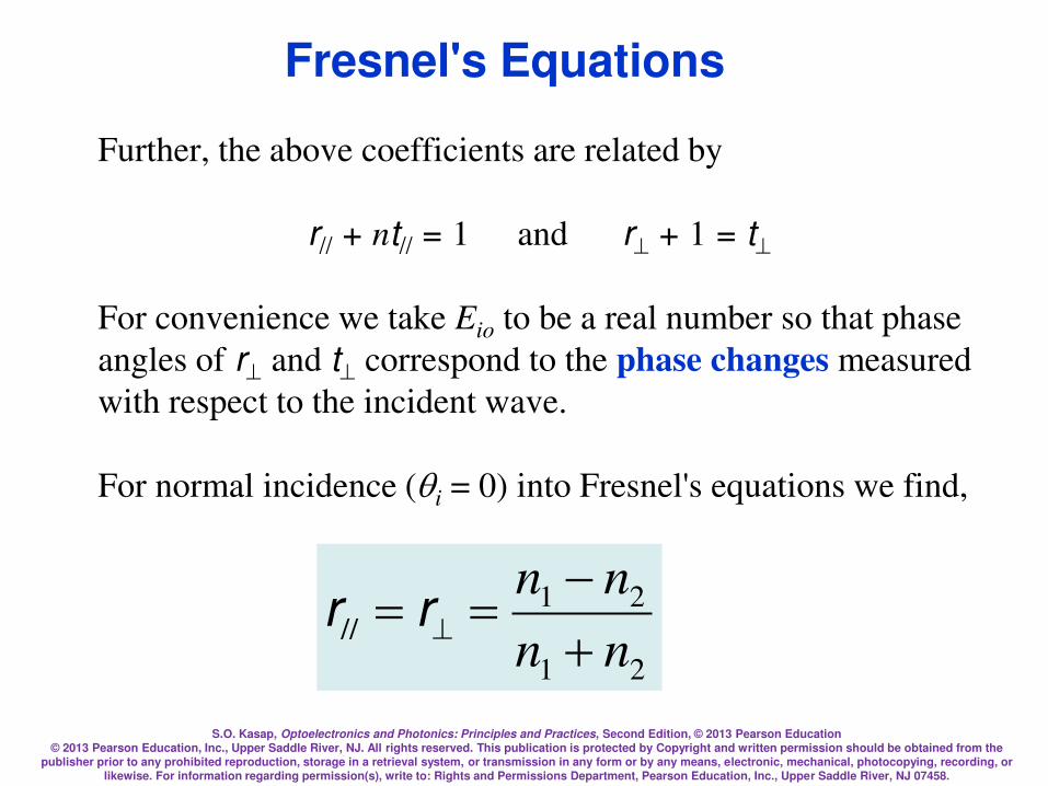
S.O. Kasap, Optoelectronics and Photonics: Principles and Practices, Second Edition, © 2013 Pearson Education © 2013 Pearson Education, Inc., Upper Saddle River, NJ. All rights reserved. This publication is protected by Copyright and written permission should be obtained from the
publisher prior to any prohibited reproduction, storage in a retrieval system, or transmission in any form or by any means, electronic, mechanical, photocopying, recording, or likewise. For information regarding permission(s), write to: Rights and Permissions Department, Pearson Education, Inc., Upper Saddle River, NJ 07458.
Further, the above coefficients are related by
r// + nt// = 1 and r + 1 = t
For convenience we take Eio to be a real number so that phase
angles of r and t correspond to the phase changes measured
with respect to the incident wave.
For normal incidence (qi = 0) into Fresnel's equations we find,
21
21//
nn
nn
== rr
Fresnel's Equations
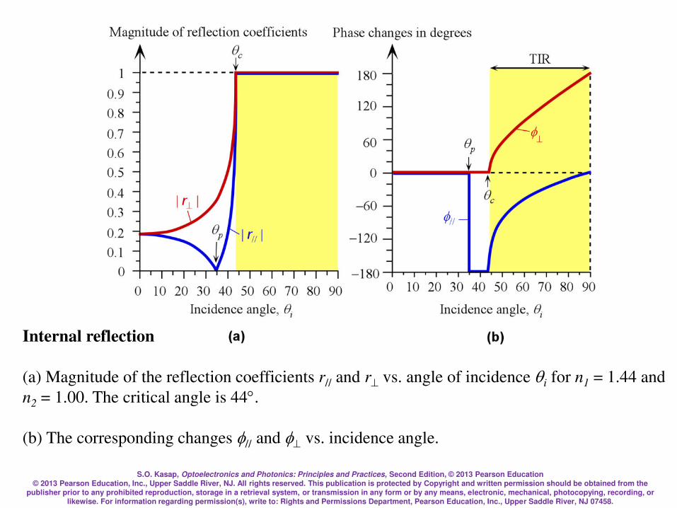
S.O. Kasap, Optoelectronics and Photonics: Principles and Practices, Second Edition, © 2013 Pearson Education © 2013 Pearson Education, Inc., Upper Saddle River, NJ. All rights reserved. This publication is protected by Copyright and written permission should be obtained from the
publisher prior to any prohibited reproduction, storage in a retrieval system, or transmission in any form or by any means, electronic, mechanical, photocopying, recording, or likewise. For information regarding permission(s), write to: Rights and Permissions Department, Pearson Education, Inc., Upper Saddle River, NJ 07458.
Internal reflection
(a) Magnitude of the reflection coefficients r// and r vs. angle of incidence qi for n1 = 1.44 and
n2 = 1.00. The critical angle is 44.
(b) The corresponding changes // and vs. incidence angle.

S.O. Kasap, Optoelectronics and Photonics: Principles and Practices, Second Edition, © 2013 Pearson Education © 2013 Pearson Education, Inc., Upper Saddle River, NJ. All rights reserved. This publication is protected by Copyright and written permission should be obtained from the
publisher prior to any prohibited reproduction, storage in a retrieval system, or transmission in any form or by any means, electronic, mechanical, photocopying, recording, or likewise. For information regarding permission(s), write to: Rights and Permissions Department, Pearson Education, Inc., Upper Saddle River, NJ 07458.
We find a special incidence angle, labeled as qp, by solving
the Fresnel equation for r// = 0. The field in the reflected
wave is then always perpendicular to the plane of incidence
and hence well-defined. This special angle is called the
polarization angle or Brewster's angle,
1
2tann
np =q
Reflection and Polarization Angle
0
cossin
cossin22/122
22/122
//,0
//,0
// =
==
ii
ii
i
r
nn
nn
E
E
qqqq
r
For both n1 > n2
or n1 < n2.

S.O. Kasap, Optoelectronics and Photonics: Principles and Practices, Second Edition, © 2013 Pearson Education © 2013 Pearson Education, Inc., Upper Saddle River, NJ. All rights reserved. This publication is protected by Copyright and written permission should be obtained from the
publisher prior to any prohibited reproduction, storage in a retrieval system, or transmission in any form or by any means, electronic, mechanical, photocopying, recording, or likewise. For information regarding permission(s), write to: Rights and Permissions Department, Pearson Education, Inc., Upper Saddle River, NJ 07458.
Polarized Light
A linearly polarized wave has its electric field oscillations defined along a
line perpendicular to the direction of propagation, z. The field vector E and z
define a plane of polarization.
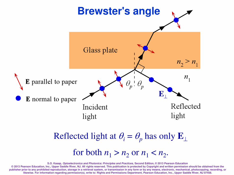
S.O. Kasap, Optoelectronics and Photonics: Principles and Practices, Second Edition, © 2013 Pearson Education © 2013 Pearson Education, Inc., Upper Saddle River, NJ. All rights reserved. This publication is protected by Copyright and written permission should be obtained from the
publisher prior to any prohibited reproduction, storage in a retrieval system, or transmission in any form or by any means, electronic, mechanical, photocopying, recording, or likewise. For information regarding permission(s), write to: Rights and Permissions Department, Pearson Education, Inc., Upper Saddle River, NJ 07458.
Brewster's angle
Reflected light at qi = qp has only E
for both n1 > n2 or n1 < n2.
E
S.O. Kasap, Optoelectronics and Photonics: Principles and Practices, Second Edition, © 2013 Pearson Education © 2013 Pearson Education, Inc., Upper Saddle River, NJ. All rights reserved. This publication is protected by Copyright and written permission should be obtained from the
publisher prior to any prohibited reproduction, storage in a retrieval system, or transmission in any form or by any means, electronic, mechanical, photocopying, recording, or likewise. For information regarding permission(s), write to: Rights and Permissions Department, Pearson Education, Inc., Upper Saddle River, NJ 07458.
In linearly polarized light, however, the field oscillations are
contained within a well defined plane. Light emitted from
many light sources such as a tungsten light bulb or an LED
diode is unpolarized and the field is randomly oriented in a
direction that is perpendicular to the direction of propagation.
At the critical angle and beyond (past 44° in the figure), i.e.
when qi qc, the magnitudes of both r// and rgo to unity so
that the reflected wave has the same amplitude as the incident
wave. The incident wave has suffered total internal
reflection, TIR.
Total Internal Reflection

S.O. Kasap, Optoelectronics and Photonics: Principles and Practices, Second Edition, © 2013 Pearson Education © 2013 Pearson Education, Inc., Upper Saddle River, NJ. All rights reserved. This publication is protected by Copyright and written permission should be obtained from the
publisher prior to any prohibited reproduction, storage in a retrieval system, or transmission in any form or by any means, electronic, mechanical, photocopying, recording, or likewise. For information regarding permission(s), write to: Rights and Permissions Department, Pearson Education, Inc., Upper Saddle River, NJ 07458.
When qi > qc, in the presence of TIR, the reflection coefficients
become complex quantities of the type
r = 1exp(j) and r// = 1exp(j)
with the phase angles and // being other than zero or 180°. The
reflected wave therefore suffers phase changes, and //, in the
components E and E//. These phase changes depend on the
incidence angle, and on n1 and n2.
The phase change is given by
i
i n
qqcos
sin
2
1tan
2122 =
Phase change upon total internal reflection

S.O. Kasap, Optoelectronics and Photonics: Principles and Practices, Second Edition, © 2013 Pearson Education © 2013 Pearson Education, Inc., Upper Saddle River, NJ. All rights reserved. This publication is protected by Copyright and written permission should be obtained from the
publisher prior to any prohibited reproduction, storage in a retrieval system, or transmission in any form or by any means, electronic, mechanical, photocopying, recording, or likewise. For information regarding permission(s), write to: Rights and Permissions Department, Pearson Education, Inc., Upper Saddle River, NJ 07458.
For the E// component, the phase change // is given by
( i
i
n
n
qqcos
sintan
2
2/122
21
//21
=
Phase change upon total internal reflection

S.O. Kasap, Optoelectronics and Photonics: Principles and Practices, Second Edition, © 2013 Pearson Education © 2013 Pearson Education, Inc., Upper Saddle River, NJ. All rights reserved. This publication is protected by Copyright and written permission should be obtained from the
publisher prior to any prohibited reproduction, storage in a retrieval system, or transmission in any form or by any means, electronic, mechanical, photocopying, recording, or likewise. For information regarding permission(s), write to: Rights and Permissions Department, Pearson Education, Inc., Upper Saddle River, NJ 07458.
The reflection coefficients r// and r versus angle of incidence qi for n1 = 1.00 and n2 = 1.44.
External Reflection
S.O. Kasap, Optoelectronics and Photonics: Principles and Practices, Second Edition, © 2013 Pearson Education © 2013 Pearson Education, Inc., Upper Saddle River, NJ. All rights reserved. This publication is protected by Copyright and written permission should be obtained from the
publisher prior to any prohibited reproduction, storage in a retrieval system, or transmission in any form or by any means, electronic, mechanical, photocopying, recording, or likewise. For information regarding permission(s), write to: Rights and Permissions Department, Pearson Education, Inc., Upper Saddle River, NJ 07458.
In internal reflection (n1 > n2), the amplitude of the
reflected wave from TIR is equal to the amplitude of
the incident wave but its phase has shifted.
What happens to the transmitted wave when qi > qc?
According to the boundary conditions, there must still
be an electric field in medium 2, otherwise, the
boundary conditions cannot be satisfied. When qi >
qc, the field in medium 2 is attenuated (decreases
with y, and is called the evanescent wave.
Evanescent Wave

S.O. Kasap, Optoelectronics and Photonics: Principles and Practices, Second Edition, © 2013 Pearson Education © 2013 Pearson Education, Inc., Upper Saddle River, NJ. All rights reserved. This publication is protected by Copyright and written permission should be obtained from the
publisher prior to any prohibited reproduction, storage in a retrieval system, or transmission in any form or by any means, electronic, mechanical, photocopying, recording, or likewise. For information regarding permission(s), write to: Rights and Permissions Department, Pearson Education, Inc., Upper Saddle River, NJ 07458.
When qi > qc, for a plane wave that is reflected, there is an evanescent wave at the boundary
propagating along z.

S.O. Kasap, Optoelectronics and Photonics: Principles and Practices, Second Edition, © 2013 Pearson Education © 2013 Pearson Education, Inc., Upper Saddle River, NJ. All rights reserved. This publication is protected by Copyright and written permission should be obtained from the
publisher prior to any prohibited reproduction, storage in a retrieval system, or transmission in any form or by any means, electronic, mechanical, photocopying, recording, or likewise. For information regarding permission(s), write to: Rights and Permissions Department, Pearson Education, Inc., Upper Saddle River, NJ 07458.
)(exp),,( 2
, zktjtzyE iz
y
t e
where kiz = kisinqi is the wavevector of the incident wave
along the z-axis, and 2 is an attenuation coefficient for the
electric field penetrating into medium 2
2/1
2
2
2
122 1sin
2
= i
n
nn q
Evanescent wave when plane waves are incident and reflected
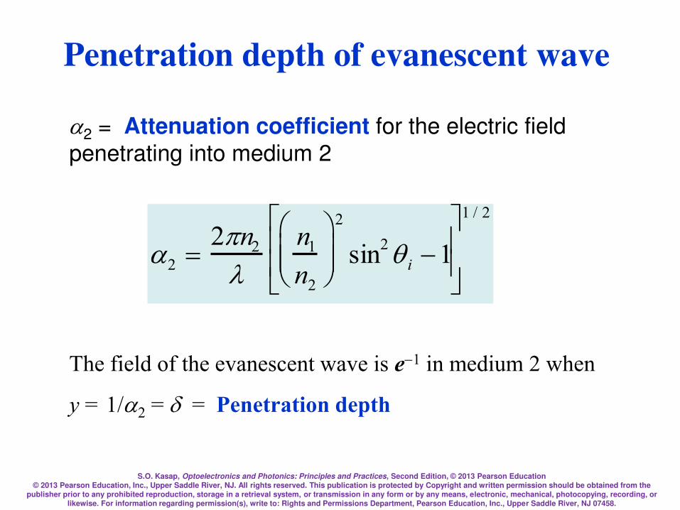
S.O. Kasap, Optoelectronics and Photonics: Principles and Practices, Second Edition, © 2013 Pearson Education © 2013 Pearson Education, Inc., Upper Saddle River, NJ. All rights reserved. This publication is protected by Copyright and written permission should be obtained from the
publisher prior to any prohibited reproduction, storage in a retrieval system, or transmission in any form or by any means, electronic, mechanical, photocopying, recording, or likewise. For information regarding permission(s), write to: Rights and Permissions Department, Pearson Education, Inc., Upper Saddle River, NJ 07458.
Penetration depth of evanescent wave
2 = Attenuation coefficient for the electric field
penetrating into medium 2
2 =2n2
n1
n2
2
sin2q i 1
1 / 2
The field of the evanescent wave is e1 in medium 2 when
y = 1/2 = = Penetration depth

S.O. Kasap, Optoelectronics and Photonics: Principles and Practices, Second Edition, © 2013 Pearson Education © 2013 Pearson Education, Inc., Upper Saddle River, NJ. All rights reserved. This publication is protected by Copyright and written permission should be obtained from the
publisher prior to any prohibited reproduction, storage in a retrieval system, or transmission in any form or by any means, electronic, mechanical, photocopying, recording, or likewise. For information regarding permission(s), write to: Rights and Permissions Department, Pearson Education, Inc., Upper Saddle River, NJ 07458.
Goos-Hänchen Shift
z = 2tanqi
qi
n2
n1
> n2
Incident
light
Reflected
light
qr
z
Virtual reflecting plane
dz
y
A
B

S.O. Kasap, Optoelectronics and Photonics: Principles and Practices, Second Edition, © 2013 Pearson Education © 2013 Pearson Education, Inc., Upper Saddle River, NJ. All rights reserved. This publication is protected by Copyright and written permission should be obtained from the
publisher prior to any prohibited reproduction, storage in a retrieval system, or transmission in any form or by any means, electronic, mechanical, photocopying, recording, or likewise. For information regarding permission(s), write to: Rights and Permissions Department, Pearson Education, Inc., Upper Saddle River, NJ 07458.
When medium B is thin (thickness d is small), the field penetrates from
the AB interface into medium B and reaches BC interface, and gives rise to
a transmitted wave in medium C. The effect is the tunneling of the
incident beam in A through B to C. The maximum field Emax of the
evanescent wave in B decays in B along y and but is finite at the BC
boundary and excites the transmitted wave.
Optical Tunneling

S.O. Kasap, Optoelectronics and Photonics: Principles and Practices, Second Edition, © 2013 Pearson Education © 2013 Pearson Education, Inc., Upper Saddle River, NJ. All rights reserved. This publication is protected by Copyright and written permission should be obtained from the
publisher prior to any prohibited reproduction, storage in a retrieval system, or transmission in any form or by any means, electronic, mechanical, photocopying, recording, or likewise. For information regarding permission(s), write to: Rights and Permissions Department, Pearson Education, Inc., Upper Saddle River, NJ 07458.
Beam Splitters Frustrated Total Internal Reflection (FTIR)
(a) A light incident at the
long face of a glass prism
suffers TIR; the prism
deflects the light.
(b) Two prisms separated by a thin low
refractive index film forming a beam-splitter
cube. The incident beam is split into two
beams by FTIR.
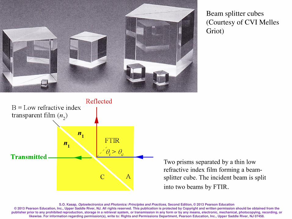
S.O. Kasap, Optoelectronics and Photonics: Principles and Practices, Second Edition, © 2013 Pearson Education © 2013 Pearson Education, Inc., Upper Saddle River, NJ. All rights reserved. This publication is protected by Copyright and written permission should be obtained from the
publisher prior to any prohibited reproduction, storage in a retrieval system, or transmission in any form or by any means, electronic, mechanical, photocopying, recording, or likewise. For information regarding permission(s), write to: Rights and Permissions Department, Pearson Education, Inc., Upper Saddle River, NJ 07458.
Two prisms separated by a thin low
refractive index film forming a beam-
splitter cube. The incident beam is split
into two beams by FTIR.
Beam splitter cubes
(Courtesy of CVI Melles
Griot)

S.O. Kasap, Optoelectronics and Photonics: Principles and Practices, Second Edition, © 2013 Pearson Education © 2013 Pearson Education, Inc., Upper Saddle River, NJ. All rights reserved. This publication is protected by Copyright and written permission should be obtained from the
publisher prior to any prohibited reproduction, storage in a retrieval system, or transmission in any form or by any means, electronic, mechanical, photocopying, recording, or likewise. For information regarding permission(s), write to: Rights and Permissions Department, Pearson Education, Inc., Upper Saddle River, NJ 07458.
Optical Tunneling
Light propagation along an
optical guide by total
internal reflections
Coupling of laser light into a thin layer
- optical guide - using a prism. The
light propagates along the thin layer.
S.O. Kasap, Optoelectronics and Photonics: Principles and Practices, Second Edition, © 2013 Pearson Education © 2013 Pearson Education, Inc., Upper Saddle River, NJ. All rights reserved. This publication is protected by Copyright and written permission should be obtained from the
publisher prior to any prohibited reproduction, storage in a retrieval system, or transmission in any form or by any means, electronic, mechanical, photocopying, recording, or likewise. For information regarding permission(s), write to: Rights and Permissions Department, Pearson Education, Inc., Upper Saddle River, NJ 07458.
Light approaches the boundary from the lower index side,
n1 < n2
This is external reflection.
Light becomes reflected by the surface of an optically denser
(higher refractive index) medium.
r and r// depend on the incidence angle qi. At normal
incidence, r and r// are negative. In external reflection at
normal incidence there is a phase shift of 180°. r// goes
through zero at the Brewster angle, qp. At qp, the reflected
wave is polarized in the E component only.
Transmitted light in both internal reflection (when qi < qc) and
external reflection does not experience a phase shift.
External Reflection
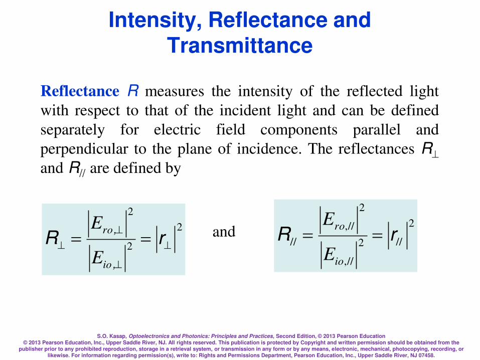
S.O. Kasap, Optoelectronics and Photonics: Principles and Practices, Second Edition, © 2013 Pearson Education © 2013 Pearson Education, Inc., Upper Saddle River, NJ. All rights reserved. This publication is protected by Copyright and written permission should be obtained from the
publisher prior to any prohibited reproduction, storage in a retrieval system, or transmission in any form or by any means, electronic, mechanical, photocopying, recording, or likewise. For information regarding permission(s), write to: Rights and Permissions Department, Pearson Education, Inc., Upper Saddle River, NJ 07458.
Intensity, Reflectance and Transmittance
Reflectance R measures the intensity of the reflected light
with respect to that of the incident light and can be defined
separately for electric field components parallel and
perpendicular to the plane of incidence. The reflectances R
and R// are defined by
2
2
2
== rR
,
,
io
ro
E
Eand
2
//2
//,
2
//,
// rR ==io
ro
E
E

S.O. Kasap, Optoelectronics and Photonics: Principles and Practices, Second Edition, © 2013 Pearson Education © 2013 Pearson Education, Inc., Upper Saddle River, NJ. All rights reserved. This publication is protected by Copyright and written permission should be obtained from the
publisher prior to any prohibited reproduction, storage in a retrieval system, or transmission in any form or by any means, electronic, mechanical, photocopying, recording, or likewise. For information regarding permission(s), write to: Rights and Permissions Department, Pearson Education, Inc., Upper Saddle River, NJ 07458.
At normal incidence
2
21
21//
=== nn
nnRRR
Since a glass medium has a refractive index of
around 1.5 this means that typically 4% of the
incident radiation on an air-glass surface will be
reflected back.

S.O. Kasap, Optoelectronics and Photonics: Principles and Practices, Second Edition, © 2013 Pearson Education © 2013 Pearson Education, Inc., Upper Saddle River, NJ. All rights reserved. This publication is protected by Copyright and written permission should be obtained from the
publisher prior to any prohibited reproduction, storage in a retrieval system, or transmission in any form or by any means, electronic, mechanical, photocopying, recording, or likewise. For information regarding permission(s), write to: Rights and Permissions Department, Pearson Education, Inc., Upper Saddle River, NJ 07458.
Example: Reflection at normal incidence. Internal and external reflection
Consider the reflection of light at normal incidence on a boundary
between a glass medium of refractive index 1.5 and air of refractive index 1. (a) If light is traveling from air to glass, what is the reflection coefficient and the intensity of the reflected light with respect to that of the incident light? (b) If light is traveling from glass to air, what is the reflection coefficient and the intensity of the reflected light with respect to
that of the incident light? (c) What is the polarization angle in the external reflection in a above? How would you make a polaroid from this?
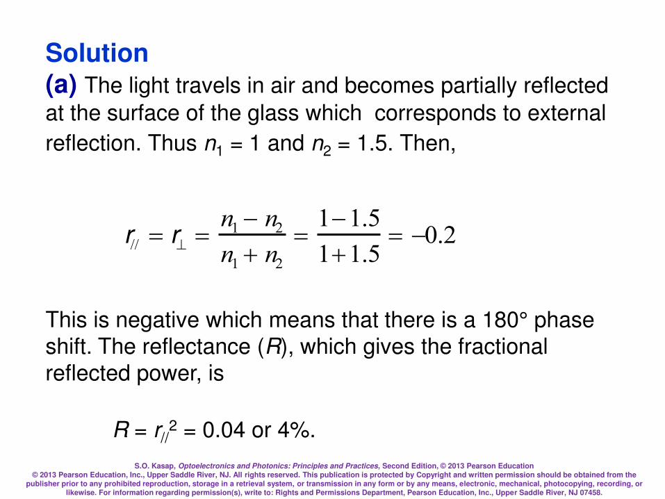
S.O. Kasap, Optoelectronics and Photonics: Principles and Practices, Second Edition, © 2013 Pearson Education © 2013 Pearson Education, Inc., Upper Saddle River, NJ. All rights reserved. This publication is protected by Copyright and written permission should be obtained from the
publisher prior to any prohibited reproduction, storage in a retrieval system, or transmission in any form or by any means, electronic, mechanical, photocopying, recording, or likewise. For information regarding permission(s), write to: Rights and Permissions Department, Pearson Education, Inc., Upper Saddle River, NJ 07458.
Solution (a) The light travels in air and becomes partially reflected
at the surface of the glass which corresponds to external
reflection. Thus n1 = 1 and n2 = 1.5. Then,
r// = r =n1 n2
n1 n2
=11.5
11.5= 0.2
This is negative which means that there is a 180° phase
shift. The reflectance (R), which gives the fractional
reflected power, is
R = r//2 = 0.04 or 4%.
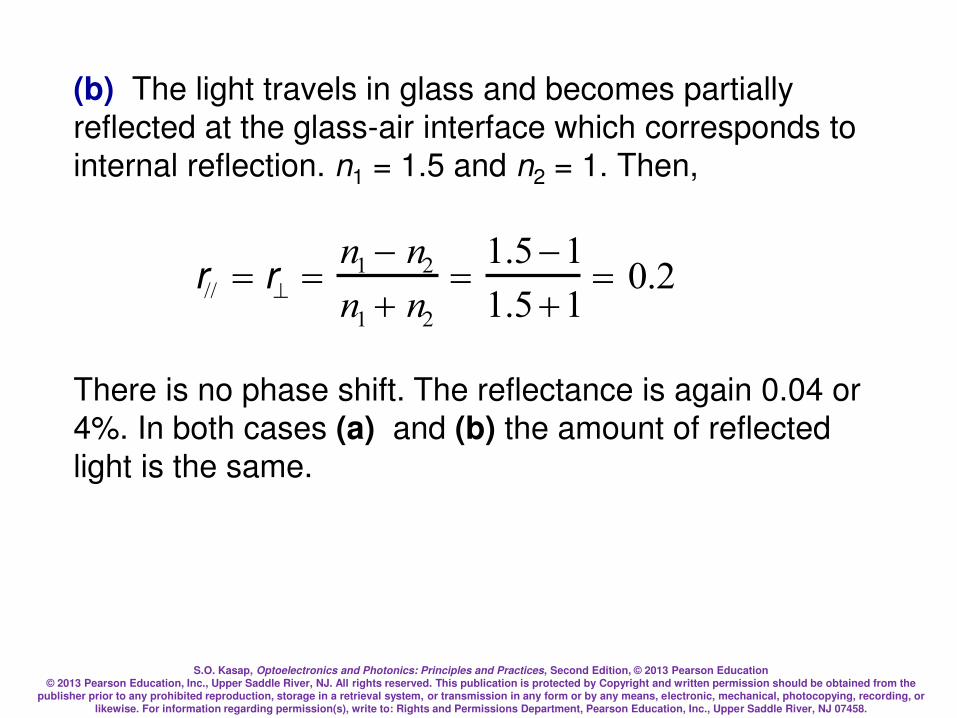
S.O. Kasap, Optoelectronics and Photonics: Principles and Practices, Second Edition, © 2013 Pearson Education © 2013 Pearson Education, Inc., Upper Saddle River, NJ. All rights reserved. This publication is protected by Copyright and written permission should be obtained from the
publisher prior to any prohibited reproduction, storage in a retrieval system, or transmission in any form or by any means, electronic, mechanical, photocopying, recording, or likewise. For information regarding permission(s), write to: Rights and Permissions Department, Pearson Education, Inc., Upper Saddle River, NJ 07458.
(b) The light travels in glass and becomes partially
reflected at the glass-air interface which corresponds to
internal reflection. n1 = 1.5 and n2 = 1. Then,
r// = r =n1 n2
n1 n2
=1.51
1.51= 0.2
There is no phase shift. The reflectance is again 0.04 or
4%. In both cases (a) and (b) the amount of reflected
light is the same.
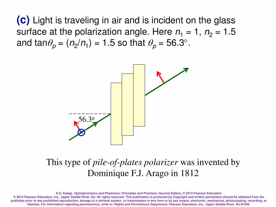
S.O. Kasap, Optoelectronics and Photonics: Principles and Practices, Second Edition, © 2013 Pearson Education © 2013 Pearson Education, Inc., Upper Saddle River, NJ. All rights reserved. This publication is protected by Copyright and written permission should be obtained from the
publisher prior to any prohibited reproduction, storage in a retrieval system, or transmission in any form or by any means, electronic, mechanical, photocopying, recording, or likewise. For information regarding permission(s), write to: Rights and Permissions Department, Pearson Education, Inc., Upper Saddle River, NJ 07458.
(c) Light is traveling in air and is incident on the glass
surface at the polarization angle. Here n1 = 1, n2 = 1.5
and tanqp = (n2/n1) = 1.5 so that qp = 56.3.
This type of pile-of-plates polarizer was invented by
Dominique F.J. Arago in 1812
56.3o

S.O. Kasap, Optoelectronics and Photonics: Principles and Practices, Second Edition, © 2013 Pearson Education © 2013 Pearson Education, Inc., Upper Saddle River, NJ. All rights reserved. This publication is protected by Copyright and written permission should be obtained from the
publisher prior to any prohibited reproduction, storage in a retrieval system, or transmission in any form or by any means, electronic, mechanical, photocopying, recording, or likewise. For information regarding permission(s), write to: Rights and Permissions Department, Pearson Education, Inc., Upper Saddle River, NJ 07458.
Transmittance T relates the intensity of the transmitted wave
to that of the incident wave in a similar fashion to the
reflectance.
However the transmitted wave is in a different medium and
further its direction with respect to the boundary is also
different due to refraction.
For normal incidence, the incident and transmitted beams are
normal so that the equations are simple:
Transmittance

S.O. Kasap, Optoelectronics and Photonics: Principles and Practices, Second Edition, © 2013 Pearson Education © 2013 Pearson Education, Inc., Upper Saddle River, NJ. All rights reserved. This publication is protected by Copyright and written permission should be obtained from the
publisher prior to any prohibited reproduction, storage in a retrieval system, or transmission in any form or by any means, electronic, mechanical, photocopying, recording, or likewise. For information regarding permission(s), write to: Rights and Permissions Department, Pearson Education, Inc., Upper Saddle River, NJ 07458.
2
1
2
2
1
2
2
== tT
n
n
En
En
io
to
,
,
or
2
//
1
2
2
//,1
2
//,2
// tT
==
n
n
En
En
io
to
( 221
21//
4
nn
nn
=== TTT
Further, the fraction of light reflected and fraction transmitted
must add to unity. Thus R + T = 1.
Transmittance
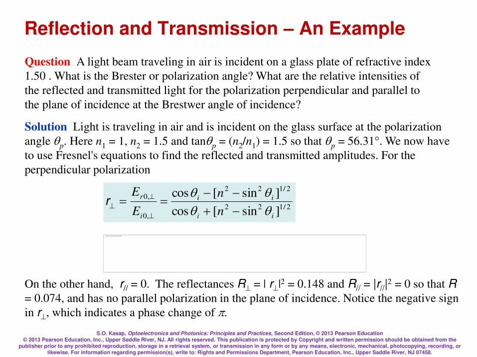
S.O. Kasap, Optoelectronics and Photonics: Principles and Practices, Second Edition, © 2013 Pearson Education © 2013 Pearson Education, Inc., Upper Saddle River, NJ. All rights reserved. This publication is protected by Copyright and written permission should be obtained from the
publisher prior to any prohibited reproduction, storage in a retrieval system, or transmission in any form or by any means, electronic, mechanical, photocopying, recording, or likewise. For information regarding permission(s), write to: Rights and Permissions Department, Pearson Education, Inc., Upper Saddle River, NJ 07458.
Reflection and Transmission – An Example
Question A light beam traveling in air is incident on a glass plate of refractive index
1.50 . What is the Brester or polarization angle? What are the relative intensities of
the reflected and transmitted light for the polarization perpendicular and parallel to
the plane of incidence at the Brestwer angle of incidence?
Solution Light is traveling in air and is incident on the glass surface at the polarization
angle qp. Here n1 = 1, n2 = 1.5 and tanqp = (n2/n1) = 1.5 so that qp = 56.31°. We now have
to use Fresnel's equations to find the reflected and transmitted amplitudes. For the
perpendicular polarization
On the other hand, r// = 0. The reflectances R = | r|2 = 0.148 and R// = |r//|2 = 0 so that R
= 0.074, and has no parallel polarization in the plane of incidence. Notice the negative sign
in r, which indicates a phase change of .
2/122
2/122
,0
,0
]sin[cos
]sin[cos
ii
ii
i
r
n
n
E
E
qqqq
==
r
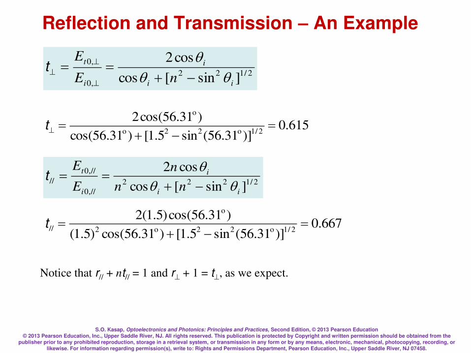
S.O. Kasap, Optoelectronics and Photonics: Principles and Practices, Second Edition, © 2013 Pearson Education © 2013 Pearson Education, Inc., Upper Saddle River, NJ. All rights reserved. This publication is protected by Copyright and written permission should be obtained from the
publisher prior to any prohibited reproduction, storage in a retrieval system, or transmission in any form or by any means, electronic, mechanical, photocopying, recording, or likewise. For information regarding permission(s), write to: Rights and Permissions Department, Pearson Education, Inc., Upper Saddle River, NJ 07458.
Reflection and Transmission – An Example
615.0)]31.56(sin5.1[)31.56cos(
)31.56cos(22/1o22o
o
=
=t
667.0)]31.56(sin5.1[)31.56cos()5.1(
)31.56cos()5.1(22/1o22o2
o
// =
=t
Notice that r// + nt// = 1 and r + 1 = t, as we expect.
2/122
,0
,0
]sin[cos
cos2
ii
i
i
t
nE
E
qqq
==
t
2/1222
//,0
//,0
//]sin[cos
cos2
ii
i
i
t
nn
n
E
E
qqq
==t
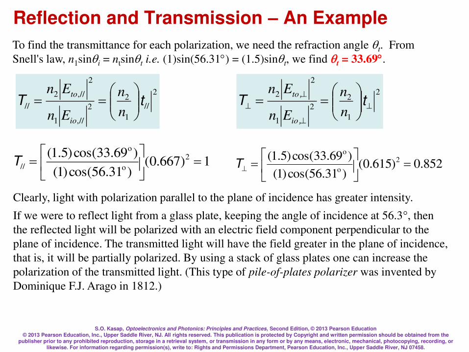
S.O. Kasap, Optoelectronics and Photonics: Principles and Practices, Second Edition, © 2013 Pearson Education © 2013 Pearson Education, Inc., Upper Saddle River, NJ. All rights reserved. This publication is protected by Copyright and written permission should be obtained from the
publisher prior to any prohibited reproduction, storage in a retrieval system, or transmission in any form or by any means, electronic, mechanical, photocopying, recording, or likewise. For information regarding permission(s), write to: Rights and Permissions Department, Pearson Education, Inc., Upper Saddle River, NJ 07458.
Reflection and Transmission – An Example
852.0)615.0()31.56cos()1(
)69.33cos()5.1( 2
o
o
=
=T1)667.0(
)31.56cos()1(
)69.33cos()5.1( 2
o
o
// =
=T
Clearly, light with polarization parallel to the plane of incidence has greater intensity.
If we were to reflect light from a glass plate, keeping the angle of incidence at 56.3°, then
the reflected light will be polarized with an electric field component perpendicular to the
plane of incidence. The transmitted light will have the field greater in the plane of incidence,
that is, it will be partially polarized. By using a stack of glass plates one can increase the
polarization of the transmitted light. (This type of pile-of-plates polarizer was invented by
Dominique F.J. Arago in 1812.)
To find the transmittance for each polarization, we need the refraction angle qt. From
Snell's law, n1sinqi = ntsinqt i.e. (1)sin(56.31) = (1.5)sinqt, we find qt = 33.69.
2
1
2
2
1
2
2
== tT
n
n
En
En
io
to
,
,2
//
1
2
2
//,1
2
//,2
// tT
==
n
n
En
En
io
to
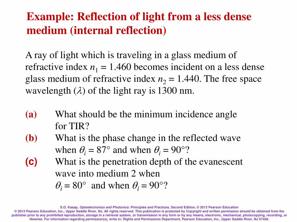
S.O. Kasap, Optoelectronics and Photonics: Principles and Practices, Second Edition, © 2013 Pearson Education © 2013 Pearson Education, Inc., Upper Saddle River, NJ. All rights reserved. This publication is protected by Copyright and written permission should be obtained from the
publisher prior to any prohibited reproduction, storage in a retrieval system, or transmission in any form or by any means, electronic, mechanical, photocopying, recording, or likewise. For information regarding permission(s), write to: Rights and Permissions Department, Pearson Education, Inc., Upper Saddle River, NJ 07458.
Example: Reflection of light from a less dense
medium (internal reflection)
A ray of light which is traveling in a glass medium of
refractive index n1 = 1.460 becomes incident on a less dense
glass medium of refractive index n2 = 1.440. The free space
wavelength () of the light ray is 1300 nm.
(a) What should be the minimum incidence angle
for TIR?
(b) What is the phase change in the reflected wave
when qi = 87° and when qi = 90°?
(c) What is the penetration depth of the evanescent
wave into medium 2 when
qi = 80° and when qi = 90°?
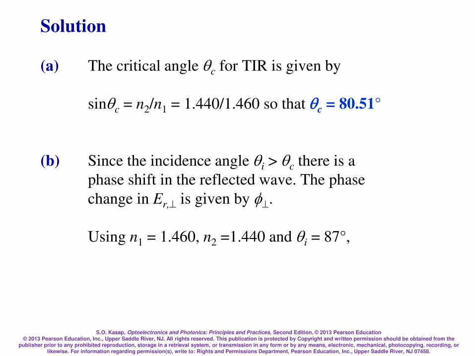
S.O. Kasap, Optoelectronics and Photonics: Principles and Practices, Second Edition, © 2013 Pearson Education © 2013 Pearson Education, Inc., Upper Saddle River, NJ. All rights reserved. This publication is protected by Copyright and written permission should be obtained from the
publisher prior to any prohibited reproduction, storage in a retrieval system, or transmission in any form or by any means, electronic, mechanical, photocopying, recording, or likewise. For information regarding permission(s), write to: Rights and Permissions Department, Pearson Education, Inc., Upper Saddle River, NJ 07458.
Solution
(a) The critical angle qc for TIR is given by
sinqc = n2/n1 = 1.440/1.460 so that qc = 80.51°
(b) Since the incidence angle qi > qc there is a
phase shift in the reflected wave. The phase
change in Er, is given by .
Using n1 = 1.460, n2 =1.440 and qi = 87°,
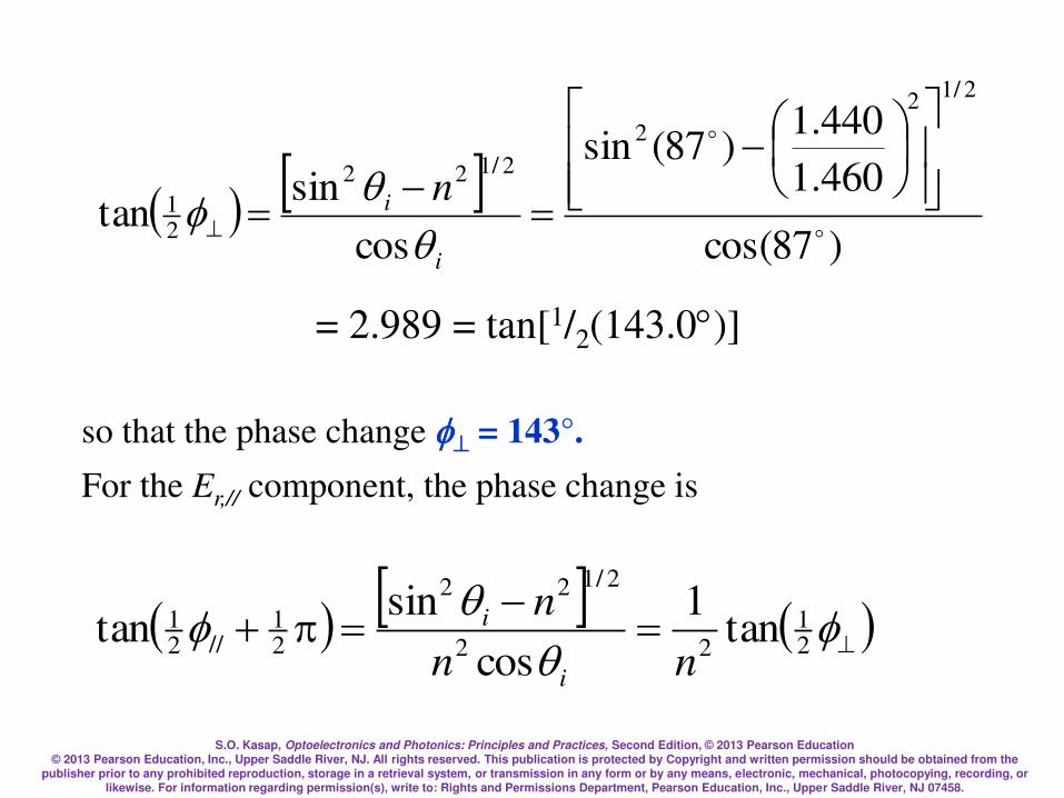
S.O. Kasap, Optoelectronics and Photonics: Principles and Practices, Second Edition, © 2013 Pearson Education © 2013 Pearson Education, Inc., Upper Saddle River, NJ. All rights reserved. This publication is protected by Copyright and written permission should be obtained from the
publisher prior to any prohibited reproduction, storage in a retrieval system, or transmission in any form or by any means, electronic, mechanical, photocopying, recording, or likewise. For information regarding permission(s), write to: Rights and Permissions Department, Pearson Education, Inc., Upper Saddle River, NJ 07458.
= 2.989 = tan[1/2(143.0)]
( )87cos(
460.1
440.1)87(sin
cos
sintan
2/12
2
2/122
21
=
=i
i n
so that the phase change = 143°.
For the Er,// component, the phase change is
( ( =
= q
q21
22
2/122
21
//21 tan
1
cos
sintan
nn
n
i
i

S.O. Kasap, Optoelectronics and Photonics: Principles and Practices, Second Edition, © 2013 Pearson Education © 2013 Pearson Education, Inc., Upper Saddle River, NJ. All rights reserved. This publication is protected by Copyright and written permission should be obtained from the
publisher prior to any prohibited reproduction, storage in a retrieval system, or transmission in any form or by any means, electronic, mechanical, photocopying, recording, or likewise. For information regarding permission(s), write to: Rights and Permissions Department, Pearson Education, Inc., Upper Saddle River, NJ 07458.
so that
tan(1/2// + 1/2π) = (n1/n2)2tan(/2) =
(1.460/1.440)2tan(1/2143°)
which gives // = 143.95180 or 36.05°
Repeat with qi = 90° to find = 180 and // = 0.
Note that as long as qi > qc, the magnitude of the reflection
coefficients are unity. Only the phase changes.

S.O. Kasap, Optoelectronics and Photonics: Principles and Practices, Second Edition, © 2013 Pearson Education © 2013 Pearson Education, Inc., Upper Saddle River, NJ. All rights reserved. This publication is protected by Copyright and written permission should be obtained from the
publisher prior to any prohibited reproduction, storage in a retrieval system, or transmission in any form or by any means, electronic, mechanical, photocopying, recording, or likewise. For information regarding permission(s), write to: Rights and Permissions Department, Pearson Education, Inc., Upper Saddle River, NJ 07458.
(c) The amplitude of the evanescent wave as it
penetrates into medium 2 is
Et,(y,t) Eto,exp(–2y)
The field strength drops to e-1 when y = 1/2 = , which is
called the penetration depth. The attenuation constant 2 is
2 =2n2
n1
n2
2
sin2q i 1
1 / 2

S.O. Kasap, Optoelectronics and Photonics: Principles and Practices, Second Edition, © 2013 Pearson Education © 2013 Pearson Education, Inc., Upper Saddle River, NJ. All rights reserved. This publication is protected by Copyright and written permission should be obtained from the
publisher prior to any prohibited reproduction, storage in a retrieval system, or transmission in any form or by any means, electronic, mechanical, photocopying, recording, or likewise. For information regarding permission(s), write to: Rights and Permissions Department, Pearson Education, Inc., Upper Saddle River, NJ 07458.
i.e. 2 =2 1.440(
1300 109 m( 1.460
1.440
2
sin2(87 )1
1 / 2
= 1.10106 m-1.
The penetration depth is,
=1/2 = 1/(1.104106 m) = 9.0610-7 m, or 0.906 m
For 90°, repeating the calculation, 2 = 1.164106 m-1, so that
= 1/2 = 0.859 m
The penetration is greater for smaller incidence angles
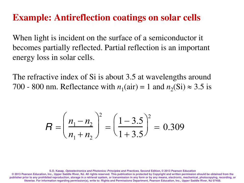
S.O. Kasap, Optoelectronics and Photonics: Principles and Practices, Second Edition, © 2013 Pearson Education © 2013 Pearson Education, Inc., Upper Saddle River, NJ. All rights reserved. This publication is protected by Copyright and written permission should be obtained from the
publisher prior to any prohibited reproduction, storage in a retrieval system, or transmission in any form or by any means, electronic, mechanical, photocopying, recording, or likewise. For information regarding permission(s), write to: Rights and Permissions Department, Pearson Education, Inc., Upper Saddle River, NJ 07458.
Example: Antireflection coatings on solar cells
When light is incident on the surface of a semiconductor it
becomes partially reflected. Partial reflection is an important
energy loss in solar cells.
The refractive index of Si is about 3.5 at wavelengths around
700 - 800 nm. Reflectance with n1(air) = 1 and n2(Si) 3.5 is
R =n1 n2
n1 n2
2
=1 3.5
1 3.5
2
= 0.309
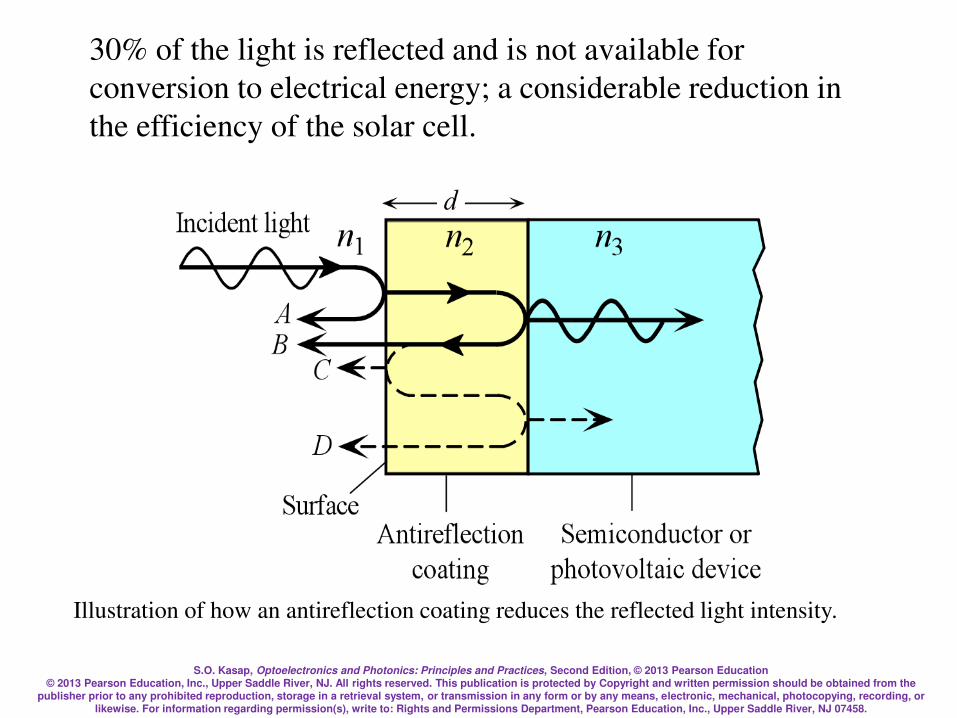
S.O. Kasap, Optoelectronics and Photonics: Principles and Practices, Second Edition, © 2013 Pearson Education © 2013 Pearson Education, Inc., Upper Saddle River, NJ. All rights reserved. This publication is protected by Copyright and written permission should be obtained from the
publisher prior to any prohibited reproduction, storage in a retrieval system, or transmission in any form or by any means, electronic, mechanical, photocopying, recording, or likewise. For information regarding permission(s), write to: Rights and Permissions Department, Pearson Education, Inc., Upper Saddle River, NJ 07458.
30% of the light is reflected and is not available for
conversion to electrical energy; a considerable reduction in
the efficiency of the solar cell.
Illustration of how an antireflection coating reduces the reflected light intensity.

S.O. Kasap, Optoelectronics and Photonics: Principles and Practices, Second Edition, © 2013 Pearson Education © 2013 Pearson Education, Inc., Upper Saddle River, NJ. All rights reserved. This publication is protected by Copyright and written permission should be obtained from the
publisher prior to any prohibited reproduction, storage in a retrieval system, or transmission in any form or by any means, electronic, mechanical, photocopying, recording, or likewise. For information regarding permission(s), write to: Rights and Permissions Department, Pearson Education, Inc., Upper Saddle River, NJ 07458.
Light is first incident on the air/coating surface. Some of it
becomes reflected as A in the figure. Wave A has experienced
a 180° phase change on reflection because this is an external
reflection. The wave that enters and travels in the coating then
becomes reflected at the coating/semiconductor surface.
We can coat the surface of the
semiconductor device with a thin
layer of a dielectric material, e.g.
Si3N4 (silicon nitride) that has an
intermediate refractive index.
n1(air) = 1, n2(coating) 1.9 and n3(Si) = 3.5
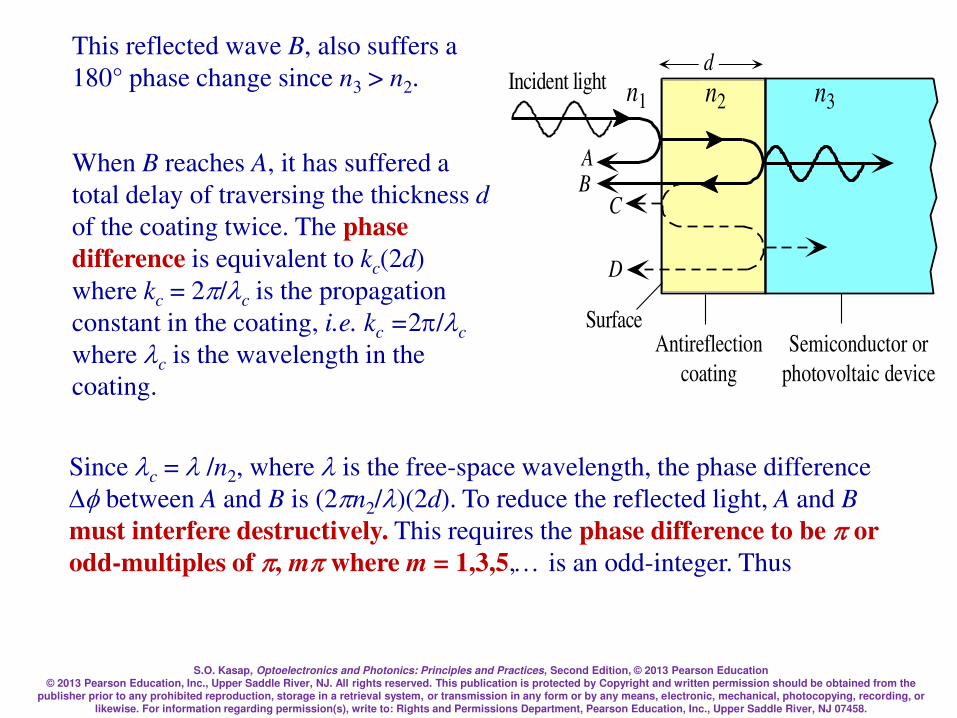
S.O. Kasap, Optoelectronics and Photonics: Principles and Practices, Second Edition, © 2013 Pearson Education © 2013 Pearson Education, Inc., Upper Saddle River, NJ. All rights reserved. This publication is protected by Copyright and written permission should be obtained from the
publisher prior to any prohibited reproduction, storage in a retrieval system, or transmission in any form or by any means, electronic, mechanical, photocopying, recording, or likewise. For information regarding permission(s), write to: Rights and Permissions Department, Pearson Education, Inc., Upper Saddle River, NJ 07458.
Since c = /n2, where is the free-space wavelength, the phase difference
between A and B is (2n2/)(2d). To reduce the reflected light, A and B
must interfere destructively. This requires the phase difference to be or
odd-multiples of , m where m = 1,3,5, is an odd-integer. Thus
d
Antireflection
coating
Surface
n1 n2 n3
AB
Semiconductor or
photovoltaic device
C
D
Incident light
This reflected wave B, also suffers a
180° phase change since n3 > n2.
When B reaches A, it has suffered a
total delay of traversing the thickness d
of the coating twice. The phase
difference is equivalent to kc(2d)
where kc = 2/c is the propagation
constant in the coating, i.e. kc =2/c
where c is the wavelength in the
coating.
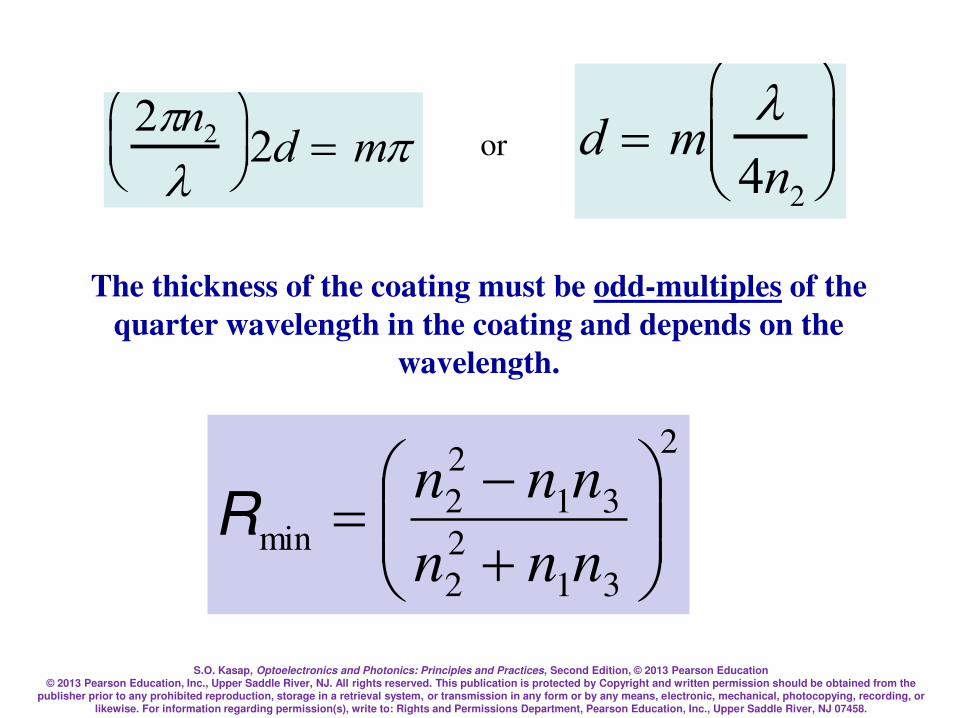
S.O. Kasap, Optoelectronics and Photonics: Principles and Practices, Second Edition, © 2013 Pearson Education © 2013 Pearson Education, Inc., Upper Saddle River, NJ. All rights reserved. This publication is protected by Copyright and written permission should be obtained from the
publisher prior to any prohibited reproduction, storage in a retrieval system, or transmission in any form or by any means, electronic, mechanical, photocopying, recording, or likewise. For information regarding permission(s), write to: Rights and Permissions Department, Pearson Education, Inc., Upper Saddle River, NJ 07458.
or 2n2
2d = m d = m
4n2
The thickness of the coating must be odd-multiples of the
quarter wavelength in the coating and depends on the
wavelength.
2
31
2
2
31
2
2min
=nnn
nnnR

S.O. Kasap, Optoelectronics and Photonics: Principles and Practices, Second Edition, © 2013 Pearson Education © 2013 Pearson Education, Inc., Upper Saddle River, NJ. All rights reserved. This publication is protected by Copyright and written permission should be obtained from the
publisher prior to any prohibited reproduction, storage in a retrieval system, or transmission in any form or by any means, electronic, mechanical, photocopying, recording, or likewise. For information regarding permission(s), write to: Rights and Permissions Department, Pearson Education, Inc., Upper Saddle River, NJ 07458.
To obtain good destructive interference between waves A and
B, the two amplitudes must be comparable. We need (proved
later) n2 = (n1n3). When n2 = (n1n3) then the reflection
coefficient between the air and coating is equal to that
between the coating and the semiconductor. For a Si solar
cell, (3.5) or 1.87. Thus, Si3N4 is a good choice as an
antireflection coating material on Si solar cells.
Taking the wavelength to be 700 nm,
d = (700 nm)/[4 (1.9)] = 92.1 nm or odd-multiples of d.
d = m
4n2
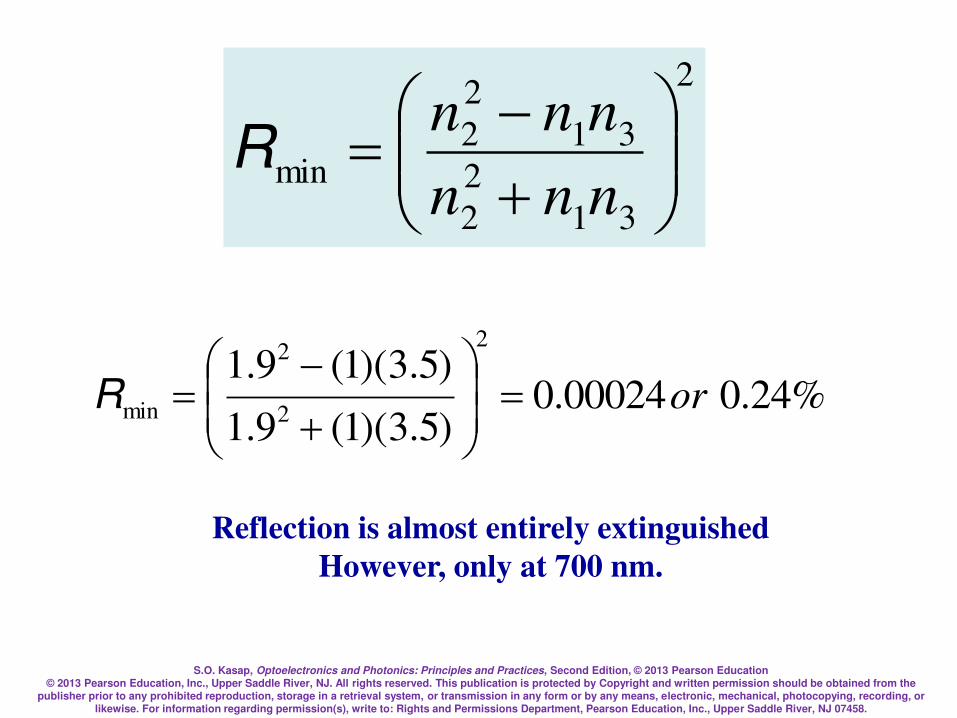
S.O. Kasap, Optoelectronics and Photonics: Principles and Practices, Second Edition, © 2013 Pearson Education © 2013 Pearson Education, Inc., Upper Saddle River, NJ. All rights reserved. This publication is protected by Copyright and written permission should be obtained from the
publisher prior to any prohibited reproduction, storage in a retrieval system, or transmission in any form or by any means, electronic, mechanical, photocopying, recording, or likewise. For information regarding permission(s), write to: Rights and Permissions Department, Pearson Education, Inc., Upper Saddle River, NJ 07458.
2
31
2
2
31
2
2min
=nnn
nnnR
%24.000024.0)5.3)(1(9.1
)5.3)(1(9.12
2
2
min or=
=R
Reflection is almost entirely extinguished
However, only at 700 nm.
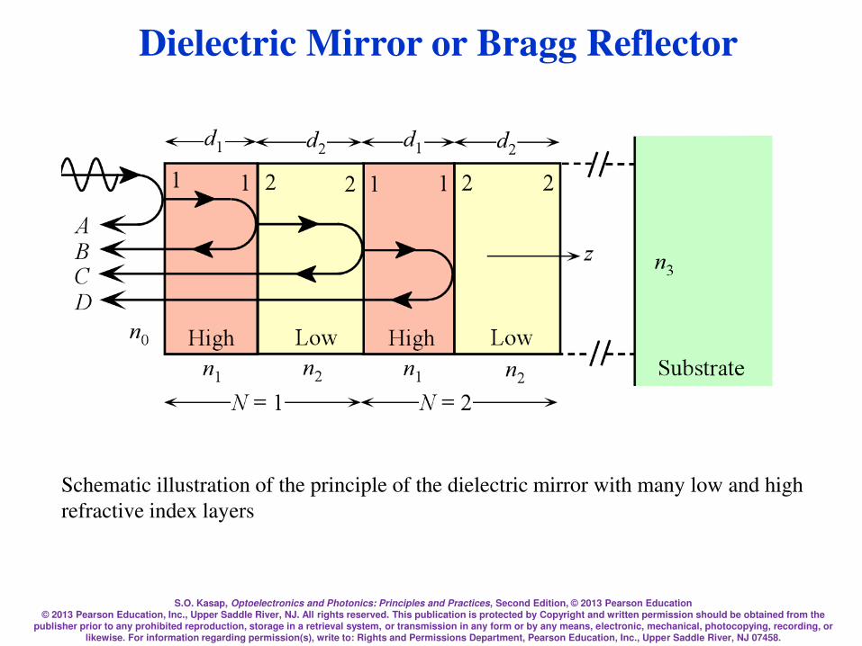
S.O. Kasap, Optoelectronics and Photonics: Principles and Practices, Second Edition, © 2013 Pearson Education © 2013 Pearson Education, Inc., Upper Saddle River, NJ. All rights reserved. This publication is protected by Copyright and written permission should be obtained from the
publisher prior to any prohibited reproduction, storage in a retrieval system, or transmission in any form or by any means, electronic, mechanical, photocopying, recording, or likewise. For information regarding permission(s), write to: Rights and Permissions Department, Pearson Education, Inc., Upper Saddle River, NJ 07458.
Dielectric Mirror or Bragg Reflector
Schematic illustration of the principle of the dielectric mirror with many low and high
refractive index layers

S.O. Kasap, Optoelectronics and Photonics: Principles and Practices, Second Edition, © 2013 Pearson Education © 2013 Pearson Education, Inc., Upper Saddle River, NJ. All rights reserved. This publication is protected by Copyright and written permission should be obtained from the
publisher prior to any prohibited reproduction, storage in a retrieval system, or transmission in any form or by any means, electronic, mechanical, photocopying, recording, or likewise. For information regarding permission(s), write to: Rights and Permissions Department, Pearson Education, Inc., Upper Saddle River, NJ 07458.
Dielectric mirrors
Schematic illustration of the principle of the dielectric mirror with many low and high
refractive index layers
d1
n1 n2
A
B
n1 n2
C
d2
D
d1 d2
z
LowHigh LowHighn0
n3
N = 1
)
Substrate
N = 2
1 2 2 1 1 21 2

S.O. Kasap, Optoelectronics and Photonics: Principles and Practices, Second Edition, © 2013 Pearson Education © 2013 Pearson Education, Inc., Upper Saddle River, NJ. All rights reserved. This publication is protected by Copyright and written permission should be obtained from the
publisher prior to any prohibited reproduction, storage in a retrieval system, or transmission in any form or by any means, electronic, mechanical, photocopying, recording, or likewise. For information regarding permission(s), write to: Rights and Permissions Department, Pearson Education, Inc., Upper Saddle River, NJ 07458.
A dielectric mirror has a stack of dielectric layers of alternating
refractive indices. Let n1 (= nH) > n2 (= nL)
Layer thickness d = Quarter of wavelength or layer
layer = o/n; o is the free space wavelength at which the mirror is
required to reflect the incident light, n = refractive index of layer.
Reflected waves from the interfaces interfere constructively and
give rise to a substantial reflected light. If there are sufficient
number of layers, the reflectance can approach unity at o.
d1
n1 n2
A
B
n1 n2
C
d2
D
d1 d2
z
LowHigh LowHighn0
n3
N = 1
)
Substrate
N = 2
1 2 2 1 1 21 2

S.O. Kasap, Optoelectronics and Photonics: Principles and Practices, Second Edition, © 2013 Pearson Education © 2013 Pearson Education, Inc., Upper Saddle River, NJ. All rights reserved. This publication is protected by Copyright and written permission should be obtained from the
publisher prior to any prohibited reproduction, storage in a retrieval system, or transmission in any form or by any means, electronic, mechanical, photocopying, recording, or likewise. For information regarding permission(s), write to: Rights and Permissions Department, Pearson Education, Inc., Upper Saddle River, NJ 07458.
r12 for light in layer 1 being reflected at the 1-2 boundary is
r12 = (n1n2)/(n1 + n2) and is a positive number indicating no phase change.
r21 for light in layer 2 being reflected at the 2-1 boundary is
r21 = (n2n1)/(n2 + n1) which is –r12 (negative) indicating a phase change.
The reflection coefficient alternates in sign through the mirror
The phase difference between A and B is
0 + + 2k1d1 = 0 + + 2(2n1/o)(o/4n1)= 2.
Thus, waves A and B are in phase and interfere constructively.
Dielectric mirrors are widely used in modern vertical cavity surface emitting
semiconductor lasers.
d1
n1 n2
A
B
n1 n2
C
d2
D
d1 d2
z
LowHigh LowHighn0
n3
N = 1
)
Substrate
N = 2
1 2 2 1 1 21 2

S.O. Kasap, Optoelectronics and Photonics: Principles and Practices, Second Edition, © 2013 Pearson Education © 2013 Pearson Education, Inc., Upper Saddle River, NJ. All rights reserved. This publication is protected by Copyright and written permission should be obtained from the
publisher prior to any prohibited reproduction, storage in a retrieval system, or transmission in any form or by any means, electronic, mechanical, photocopying, recording, or likewise. For information regarding permission(s), write to: Rights and Permissions Department, Pearson Education, Inc., Upper Saddle River, NJ 07458.
Dielectric Mirror
or Bragg Reflector
= Reflectance bandwidth
(Stop-band for transmittance)

S.O. Kasap, Optoelectronics and Photonics: Principles and Practices, Second Edition, © 2013 Pearson Education © 2013 Pearson Education, Inc., Upper Saddle River, NJ. All rights reserved. This publication is protected by Copyright and written permission should be obtained from the
publisher prior to any prohibited reproduction, storage in a retrieval system, or transmission in any form or by any means, electronic, mechanical, photocopying, recording, or likewise. For information regarding permission(s), write to: Rights and Permissions Department, Pearson Education, Inc., Upper Saddle River, NJ 07458.
Dielectric Mirror or Bragg Reflector
Consider an “infinite stack”
This is a “unit cell”

S.O. Kasap, Optoelectronics and Photonics: Principles and Practices, Second Edition, © 2013 Pearson Education © 2013 Pearson Education, Inc., Upper Saddle River, NJ. All rights reserved. This publication is protected by Copyright and written permission should be obtained from the
publisher prior to any prohibited reproduction, storage in a retrieval system, or transmission in any form or by any means, electronic, mechanical, photocopying, recording, or likewise. For information regarding permission(s), write to: Rights and Permissions Department, Pearson Education, Inc., Upper Saddle River, NJ 07458.
Dielectric Mirror or Bragg Reflector
For reflection, the phase difference between A and B must be
2k1d1 + 2k2d2= m(2)
2(2n1/)d1 + 2(2n2/)d2 = m(2)
n1d1 + n2d2 = m/2
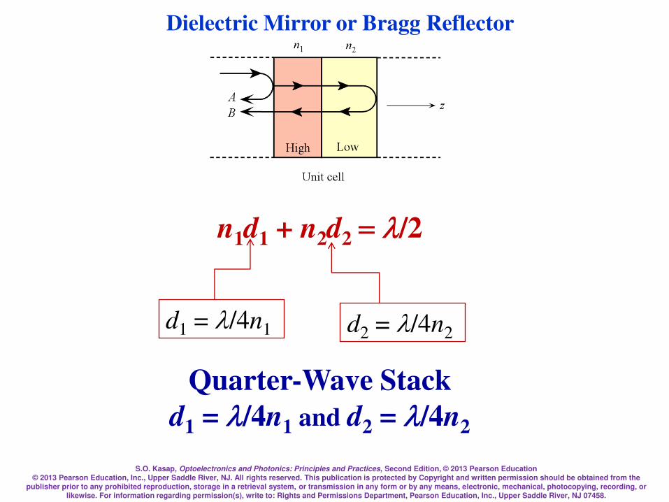
S.O. Kasap, Optoelectronics and Photonics: Principles and Practices, Second Edition, © 2013 Pearson Education © 2013 Pearson Education, Inc., Upper Saddle River, NJ. All rights reserved. This publication is protected by Copyright and written permission should be obtained from the
publisher prior to any prohibited reproduction, storage in a retrieval system, or transmission in any form or by any means, electronic, mechanical, photocopying, recording, or likewise. For information regarding permission(s), write to: Rights and Permissions Department, Pearson Education, Inc., Upper Saddle River, NJ 07458.
Dielectric Mirror or Bragg Reflector
n1d1 + n2d2 =/2
d2 = /4n2 d1 = /4n1
Quarter-Wave Stack
d1 = /4n1 and d2 = /4n2

S.O. Kasap, Optoelectronics and Photonics: Principles and Practices, Second Edition, © 2013 Pearson Education © 2013 Pearson Education, Inc., Upper Saddle River, NJ. All rights reserved. This publication is protected by Copyright and written permission should be obtained from the
publisher prior to any prohibited reproduction, storage in a retrieval system, or transmission in any form or by any means, electronic, mechanical, photocopying, recording, or likewise. For information regarding permission(s), write to: Rights and Permissions Department, Pearson Education, Inc., Upper Saddle River, NJ 07458.
Dielectric Mirror or Bragg Reflector
2
2
230
2
1
2
230
2
1
)/(
)/(
=NN
NN
nnnn
nnnnNR
21
21arcsin)/4(nn
nn
o
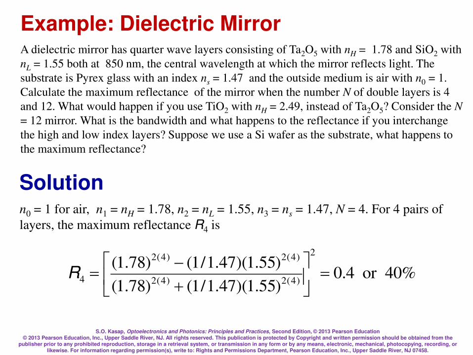
S.O. Kasap, Optoelectronics and Photonics: Principles and Practices, Second Edition, © 2013 Pearson Education © 2013 Pearson Education, Inc., Upper Saddle River, NJ. All rights reserved. This publication is protected by Copyright and written permission should be obtained from the
publisher prior to any prohibited reproduction, storage in a retrieval system, or transmission in any form or by any means, electronic, mechanical, photocopying, recording, or likewise. For information regarding permission(s), write to: Rights and Permissions Department, Pearson Education, Inc., Upper Saddle River, NJ 07458.
Example: Dielectric Mirror A dielectric mirror has quarter wave layers consisting of Ta2O5 with nH = 1.78 and SiO2 with
nL = 1.55 both at 850 nm, the central wavelength at which the mirror reflects light. The
substrate is Pyrex glass with an index ns = 1.47 and the outside medium is air with n0 = 1.
Calculate the maximum reflectance of the mirror when the number N of double layers is 4
and 12. What would happen if you use TiO2 with nH = 2.49, instead of Ta2O5? Consider the N
= 12 mirror. What is the bandwidth and what happens to the reflectance if you interchange
the high and low index layers? Suppose we use a Si wafer as the substrate, what happens to
the maximum reflectance?
Solution
%40or4.0)55.1)(47.1/1()78.1(
)55.1)(47.1/1()78.1(2
)4(2)4(2
)4(2)4(2
4 =
=R
n0 = 1 for air, n1 = nH = 1.78, n2 = nL = 1.55, n3 = ns = 1.47, N = 4. For 4 pairs of
layers, the maximum reflectance R4 is
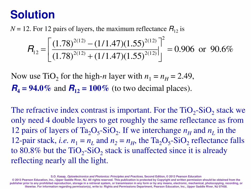
S.O. Kasap, Optoelectronics and Photonics: Principles and Practices, Second Edition, © 2013 Pearson Education © 2013 Pearson Education, Inc., Upper Saddle River, NJ. All rights reserved. This publication is protected by Copyright and written permission should be obtained from the
publisher prior to any prohibited reproduction, storage in a retrieval system, or transmission in any form or by any means, electronic, mechanical, photocopying, recording, or likewise. For information regarding permission(s), write to: Rights and Permissions Department, Pearson Education, Inc., Upper Saddle River, NJ 07458.
Solution
%6.90or906.0)55.1)(47.1/1()78.1(
)55.1)(47.1/1()78.1(2
)12(2)12(2
)12(2)12(2
12 =
=R
N = 12. For 12 pairs of layers, the maximum reflectance R12 is
Now use TiO2 for the high-n layer with n1 = nH = 2.49,
R4 = 94.0% and R12 = 100% (to two decimal places).
The refractive index contrast is important. For the TiO2-SiO2 stack we
only need 4 double layers to get roughly the same reflectance as from
12 pairs of layers of Ta2O5-SiO2. If we interchange nH and nL in the
12-pair stack, i.e. n1 = nL and n2 = nH, the Ta2O5-SiO2 reflectance falls
to 80.8% but the TiO2-SiO2 stack is unaffected since it is already
reflecting nearly all the light.
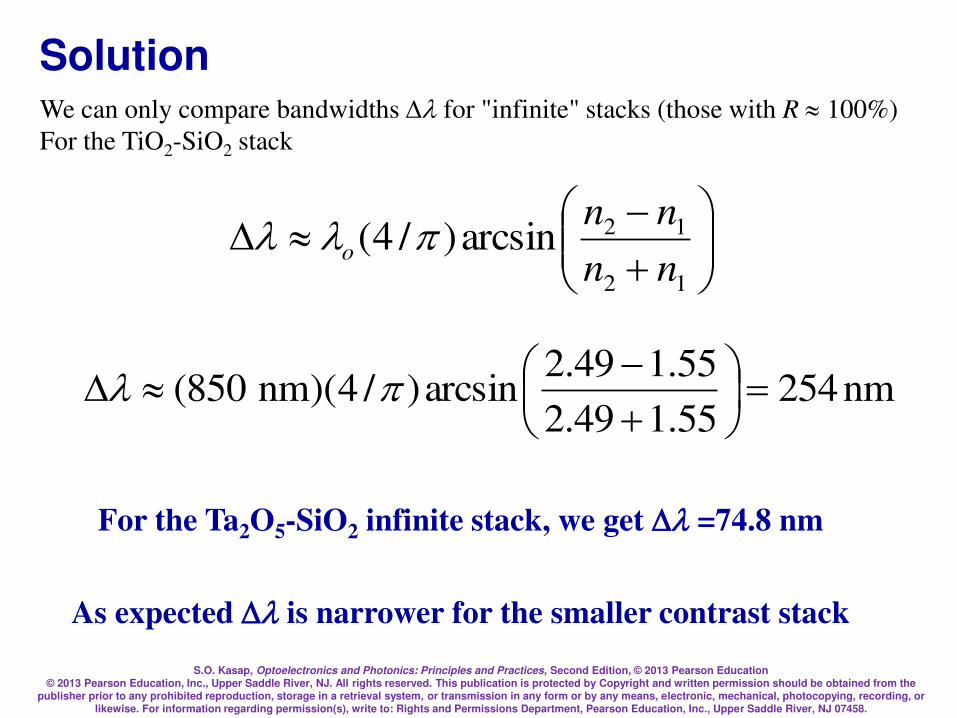
S.O. Kasap, Optoelectronics and Photonics: Principles and Practices, Second Edition, © 2013 Pearson Education © 2013 Pearson Education, Inc., Upper Saddle River, NJ. All rights reserved. This publication is protected by Copyright and written permission should be obtained from the
publisher prior to any prohibited reproduction, storage in a retrieval system, or transmission in any form or by any means, electronic, mechanical, photocopying, recording, or likewise. For information regarding permission(s), write to: Rights and Permissions Department, Pearson Education, Inc., Upper Saddle River, NJ 07458.
Solution We can only compare bandwidths for "infinite" stacks (those with R 100%)
For the TiO2-SiO2 stack
12
12arcsin)/4(nn
nno
For the Ta2O5-SiO2 infinite stack, we get =74.8 nm
As expected is narrower for the smaller contrast stack
nm25455.149.2
55.149.2arcsin)/4)(nm850( =
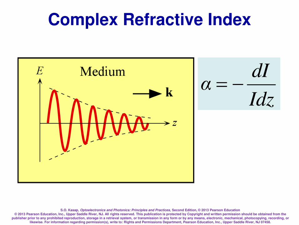
S.O. Kasap, Optoelectronics and Photonics: Principles and Practices, Second Edition, © 2013 Pearson Education © 2013 Pearson Education, Inc., Upper Saddle River, NJ. All rights reserved. This publication is protected by Copyright and written permission should be obtained from the
publisher prior to any prohibited reproduction, storage in a retrieval system, or transmission in any form or by any means, electronic, mechanical, photocopying, recording, or likewise. For information regarding permission(s), write to: Rights and Permissions Department, Pearson Education, Inc., Upper Saddle River, NJ 07458.
Complex Refractive Index
Idz
dIα =

S.O. Kasap, Optoelectronics and Photonics: Principles and Practices, Second Edition, © 2013 Pearson Education © 2013 Pearson Education, Inc., Upper Saddle River, NJ. All rights reserved. This publication is protected by Copyright and written permission should be obtained from the
publisher prior to any prohibited reproduction, storage in a retrieval system, or transmission in any form or by any means, electronic, mechanical, photocopying, recording, or likewise. For information regarding permission(s), write to: Rights and Permissions Department, Pearson Education, Inc., Upper Saddle River, NJ 07458.
Complex Refractive Index
Consider k = k jk
E = Eoexp(kz)expj(t kz)
I |E|2 exp(2kz)
We know from EM wave theory
r = r jr and N = r1/2
N = n jK = k/ko = (1/ko)[k jk]
rrr jjKn ===N
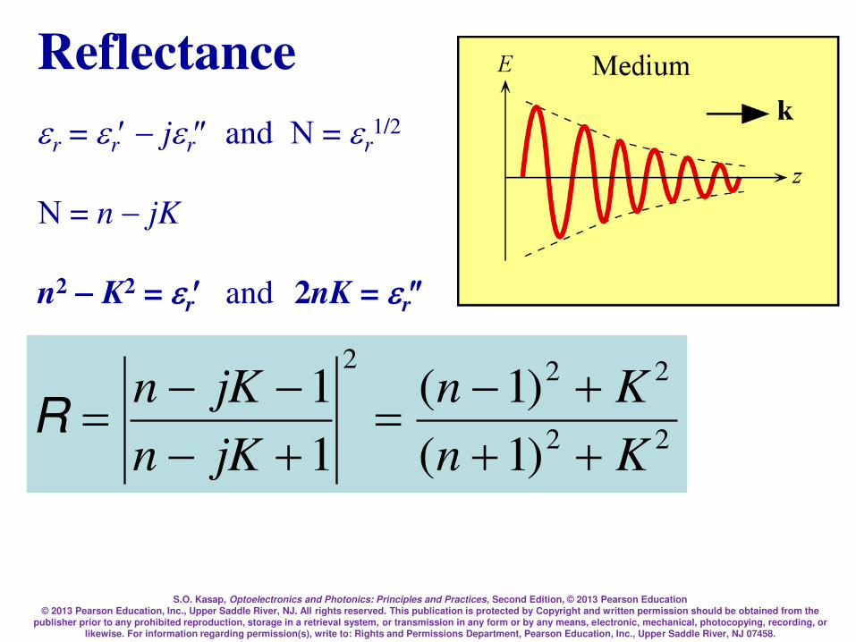
S.O. Kasap, Optoelectronics and Photonics: Principles and Practices, Second Edition, © 2013 Pearson Education © 2013 Pearson Education, Inc., Upper Saddle River, NJ. All rights reserved. This publication is protected by Copyright and written permission should be obtained from the
publisher prior to any prohibited reproduction, storage in a retrieval system, or transmission in any form or by any means, electronic, mechanical, photocopying, recording, or likewise. For information regarding permission(s), write to: Rights and Permissions Department, Pearson Education, Inc., Upper Saddle River, NJ 07458.
Reflectance
r = r jr and N = r1/2
N = n jK
n2 K2 = r and 2nK = r
22
222
)1(
)1(
1
1
Kn
Kn
jKn
jKn
=
=R
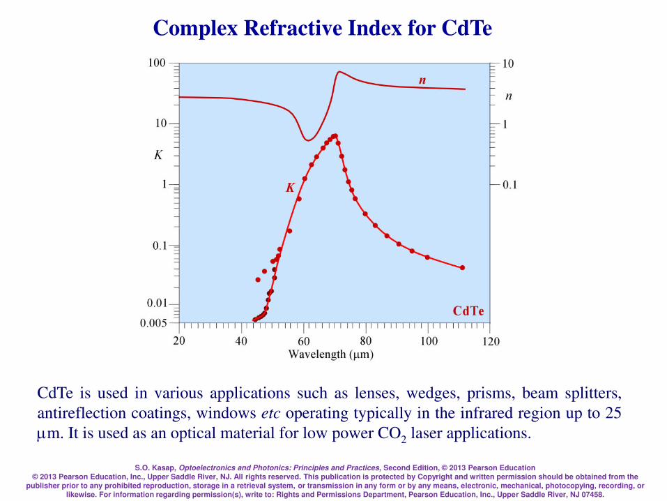
S.O. Kasap, Optoelectronics and Photonics: Principles and Practices, Second Edition, © 2013 Pearson Education © 2013 Pearson Education, Inc., Upper Saddle River, NJ. All rights reserved. This publication is protected by Copyright and written permission should be obtained from the
publisher prior to any prohibited reproduction, storage in a retrieval system, or transmission in any form or by any means, electronic, mechanical, photocopying, recording, or likewise. For information regarding permission(s), write to: Rights and Permissions Department, Pearson Education, Inc., Upper Saddle River, NJ 07458.
Complex Refractive Index for CdTe
CdTe is used in various applications such as lenses, wedges, prisms, beam splitters,
antireflection coatings, windows etc operating typically in the infrared region up to 25
m. It is used as an optical material for low power CO2 laser applications.
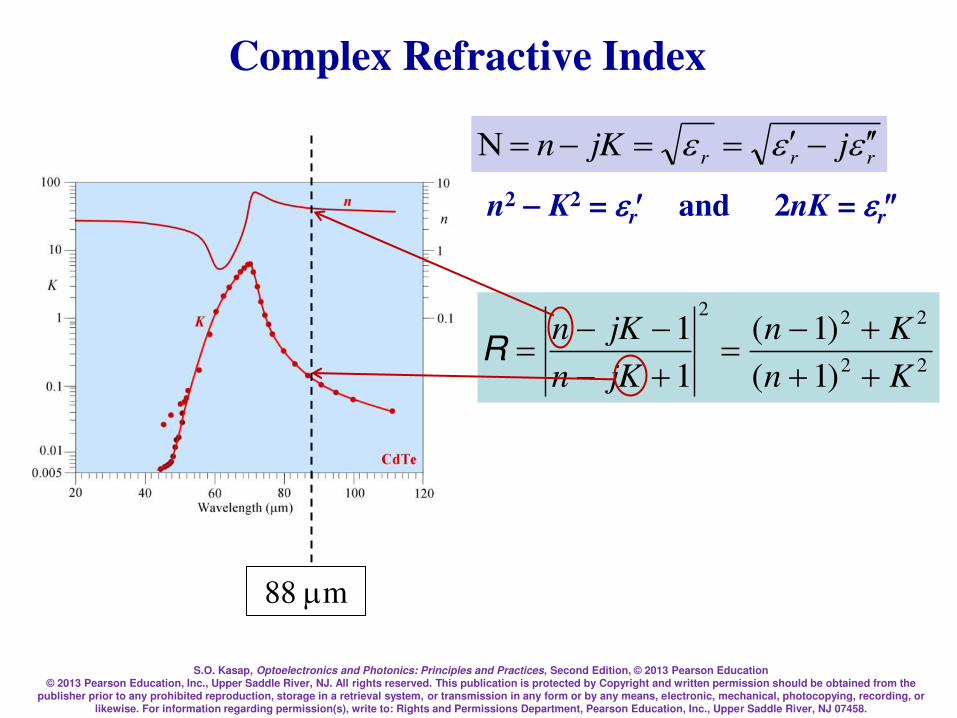
S.O. Kasap, Optoelectronics and Photonics: Principles and Practices, Second Edition, © 2013 Pearson Education © 2013 Pearson Education, Inc., Upper Saddle River, NJ. All rights reserved. This publication is protected by Copyright and written permission should be obtained from the
publisher prior to any prohibited reproduction, storage in a retrieval system, or transmission in any form or by any means, electronic, mechanical, photocopying, recording, or likewise. For information regarding permission(s), write to: Rights and Permissions Department, Pearson Education, Inc., Upper Saddle River, NJ 07458.
Complex Refractive Index
n2 K2 = r and 2nK = r
rrr jjKn ===N
22
222
)1(
)1(
1
1
Kn
Kn
jKn
jKn
=
=R
88 m
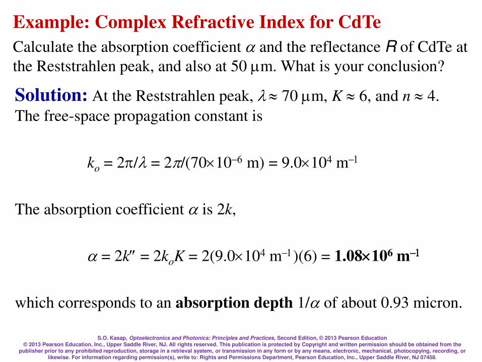
S.O. Kasap, Optoelectronics and Photonics: Principles and Practices, Second Edition, © 2013 Pearson Education © 2013 Pearson Education, Inc., Upper Saddle River, NJ. All rights reserved. This publication is protected by Copyright and written permission should be obtained from the
publisher prior to any prohibited reproduction, storage in a retrieval system, or transmission in any form or by any means, electronic, mechanical, photocopying, recording, or likewise. For information regarding permission(s), write to: Rights and Permissions Department, Pearson Education, Inc., Upper Saddle River, NJ 07458.
Example: Complex Refractive Index for CdTe
Calculate the absorption coefficient and the reflectance R of CdTe at
the Reststrahlen peak, and also at 50 m. What is your conclusion?
Solution: At the Reststrahlen peak, 70 m, K 6, and n 4.
The free-space propagation constant is
ko = 2/ = 2/(70106 m) = 9.0104 m1
The absorption coefficient is 2k,
= 2k = 2koK = 2(9.0104 m1)(6) = 1.08106 m1
which corresponds to an absorption depth 1/ of about 0.93 micron.
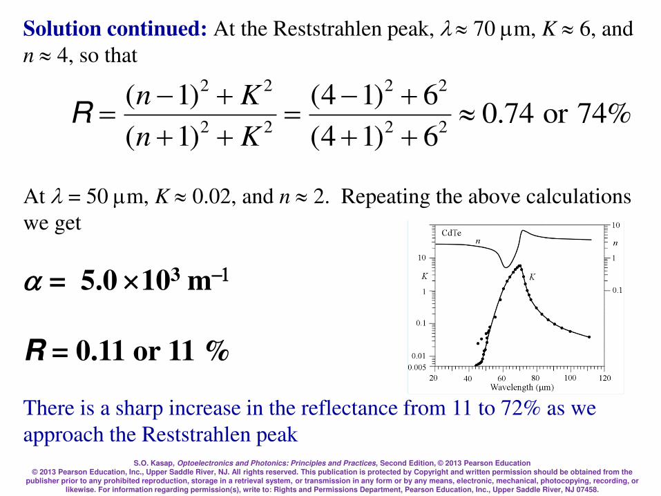
S.O. Kasap, Optoelectronics and Photonics: Principles and Practices, Second Edition, © 2013 Pearson Education © 2013 Pearson Education, Inc., Upper Saddle River, NJ. All rights reserved. This publication is protected by Copyright and written permission should be obtained from the
publisher prior to any prohibited reproduction, storage in a retrieval system, or transmission in any form or by any means, electronic, mechanical, photocopying, recording, or likewise. For information regarding permission(s), write to: Rights and Permissions Department, Pearson Education, Inc., Upper Saddle River, NJ 07458.
Solution continued: At the Reststrahlen peak, 70 m, K 6, and
n 4, so that
%74or74.06)14(
6)14(
)1(
)1(22
22
22
22
=
=Kn
KnR
At = 50 m, K 0.02, and n 2. Repeating the above calculations
we get
= 5.0 103 m1
R = 0.11 or 11 %
There is a sharp increase in the reflectance from 11 to 72% as we
approach the Reststrahlen peak
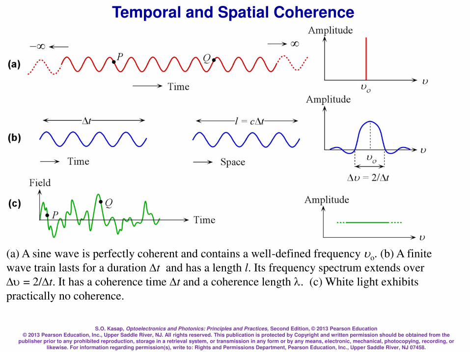
S.O. Kasap, Optoelectronics and Photonics: Principles and Practices, Second Edition, © 2013 Pearson Education © 2013 Pearson Education, Inc., Upper Saddle River, NJ. All rights reserved. This publication is protected by Copyright and written permission should be obtained from the
publisher prior to any prohibited reproduction, storage in a retrieval system, or transmission in any form or by any means, electronic, mechanical, photocopying, recording, or likewise. For information regarding permission(s), write to: Rights and Permissions Department, Pearson Education, Inc., Upper Saddle River, NJ 07458.
Temporal and Spatial Coherence
(a) A sine wave is perfectly coherent and contains a well-defined frequency uo. (b) A finite
wave train lasts for a duration t and has a length l. Its frequency spectrum extends over
u = 2/t. It has a coherence time t and a coherence length . (c) White light exhibits
practically no coherence.

S.O. Kasap, Optoelectronics and Photonics: Principles and Practices, Second Edition, © 2013 Pearson Education © 2013 Pearson Education, Inc., Upper Saddle River, NJ. All rights reserved. This publication is protected by Copyright and written permission should be obtained from the
publisher prior to any prohibited reproduction, storage in a retrieval system, or transmission in any form or by any means, electronic, mechanical, photocopying, recording, or likewise. For information regarding permission(s), write to: Rights and Permissions Department, Pearson Education, Inc., Upper Saddle River, NJ 07458.
Temporal and Spatial Coherence
t
1u

S.O. Kasap, Optoelectronics and Photonics: Principles and Practices, Second Edition, © 2013 Pearson Education © 2013 Pearson Education, Inc., Upper Saddle River, NJ. All rights reserved. This publication is protected by Copyright and written permission should be obtained from the
publisher prior to any prohibited reproduction, storage in a retrieval system, or transmission in any form or by any means, electronic, mechanical, photocopying, recording, or likewise. For information regarding permission(s), write to: Rights and Permissions Department, Pearson Education, Inc., Upper Saddle River, NJ 07458.
Temporal and Spatial Coherence
(a) Two waves can only interfere over the time interval t. (b) Spatial coherence involves
comparing the coherence of waves emitted from different locations on the source. (c) An
incoherent beam
c
(a)
Time
(b)
A
B
tInterference No interferenceNo interference
Space
c
P
Q
Source
Spatially coherent source
An incoherent beam(c)

S.O. Kasap, Optoelectronics and Photonics: Principles and Practices, Second Edition, © 2013 Pearson Education © 2013 Pearson Education, Inc., Upper Saddle River, NJ. All rights reserved. This publication is protected by Copyright and written permission should be obtained from the
publisher prior to any prohibited reproduction, storage in a retrieval system, or transmission in any form or by any means, electronic, mechanical, photocopying, recording, or likewise. For information regarding permission(s), write to: Rights and Permissions Department, Pearson Education, Inc., Upper Saddle River, NJ 07458.
Temporal and Spatial Coherence
t = coherence time
l = ct = coherence length
For a Gaussian light pulse
Spectral width Pulse duration
t
1u
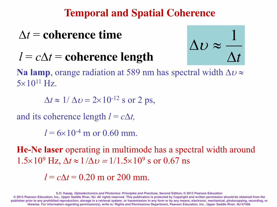
S.O. Kasap, Optoelectronics and Photonics: Principles and Practices, Second Edition, © 2013 Pearson Education © 2013 Pearson Education, Inc., Upper Saddle River, NJ. All rights reserved. This publication is protected by Copyright and written permission should be obtained from the
publisher prior to any prohibited reproduction, storage in a retrieval system, or transmission in any form or by any means, electronic, mechanical, photocopying, recording, or likewise. For information regarding permission(s), write to: Rights and Permissions Department, Pearson Education, Inc., Upper Saddle River, NJ 07458.
Temporal and Spatial Coherence
t = coherence time
l = ct = coherence length
Na lamp, orange radiation at 589 nm has spectral width u
51011 Hz.
t 1/u= 210-12 s or 2 ps,
and its coherence length l = ct,
l = 610-4 m or 0.60 mm.
He-Ne laser operating in multimode has a spectral width around
1.5109 Hz, t 1u= 1/1.5109 s or 0.67 ns
l = ct = 0.20 m or 200 mm.
t
1u

S.O. Kasap, Optoelectronics and Photonics: Principles and Practices, Second Edition, © 2013 Pearson Education © 2013 Pearson Education, Inc., Upper Saddle River, NJ. All rights reserved. This publication is protected by Copyright and written permission should be obtained from the
publisher prior to any prohibited reproduction, storage in a retrieval system, or transmission in any form or by any means, electronic, mechanical, photocopying, recording, or likewise. For information regarding permission(s), write to: Rights and Permissions Department, Pearson Education, Inc., Upper Saddle River, NJ 07458.
Interference
E1 = Eo1sin(t – kr1 –1) and E2 = Eo2sin(t – kr2 –2)
21
2
2
2
12121 2)()( EEEEEEEEEE ==
Interference results in E = E1 + E2
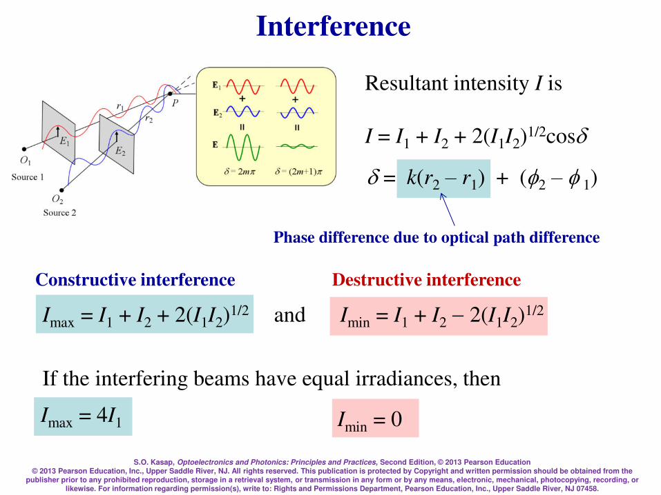
S.O. Kasap, Optoelectronics and Photonics: Principles and Practices, Second Edition, © 2013 Pearson Education © 2013 Pearson Education, Inc., Upper Saddle River, NJ. All rights reserved. This publication is protected by Copyright and written permission should be obtained from the
publisher prior to any prohibited reproduction, storage in a retrieval system, or transmission in any form or by any means, electronic, mechanical, photocopying, recording, or likewise. For information regarding permission(s), write to: Rights and Permissions Department, Pearson Education, Inc., Upper Saddle River, NJ 07458.
Interference
Resultant intensity I is
I = I1 + I2 + 2(I1I2)1/2cos
= k(r2 – r1) + (2 – 1)
Imax = I1 + I2 + 2(I1I2)1/2 and Imin = I1 + I2 2(I1I2)
1/2
If the interfering beams have equal irradiances, then
Phase difference due to optical path difference
Constructive interference Destructive interference
Imin = 0 Imax = 4I1
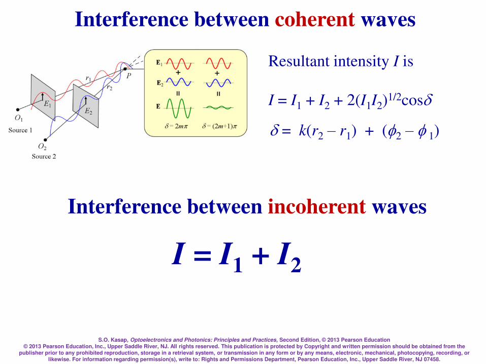
S.O. Kasap, Optoelectronics and Photonics: Principles and Practices, Second Edition, © 2013 Pearson Education © 2013 Pearson Education, Inc., Upper Saddle River, NJ. All rights reserved. This publication is protected by Copyright and written permission should be obtained from the
publisher prior to any prohibited reproduction, storage in a retrieval system, or transmission in any form or by any means, electronic, mechanical, photocopying, recording, or likewise. For information regarding permission(s), write to: Rights and Permissions Department, Pearson Education, Inc., Upper Saddle River, NJ 07458.
Interference between coherent waves
Resultant intensity I is
I = I1 + I2 + 2(I1I2)1/2cos
= k(r2 – r1) + (2 – 1)
Interference between incoherent waves
I = I1 + I2
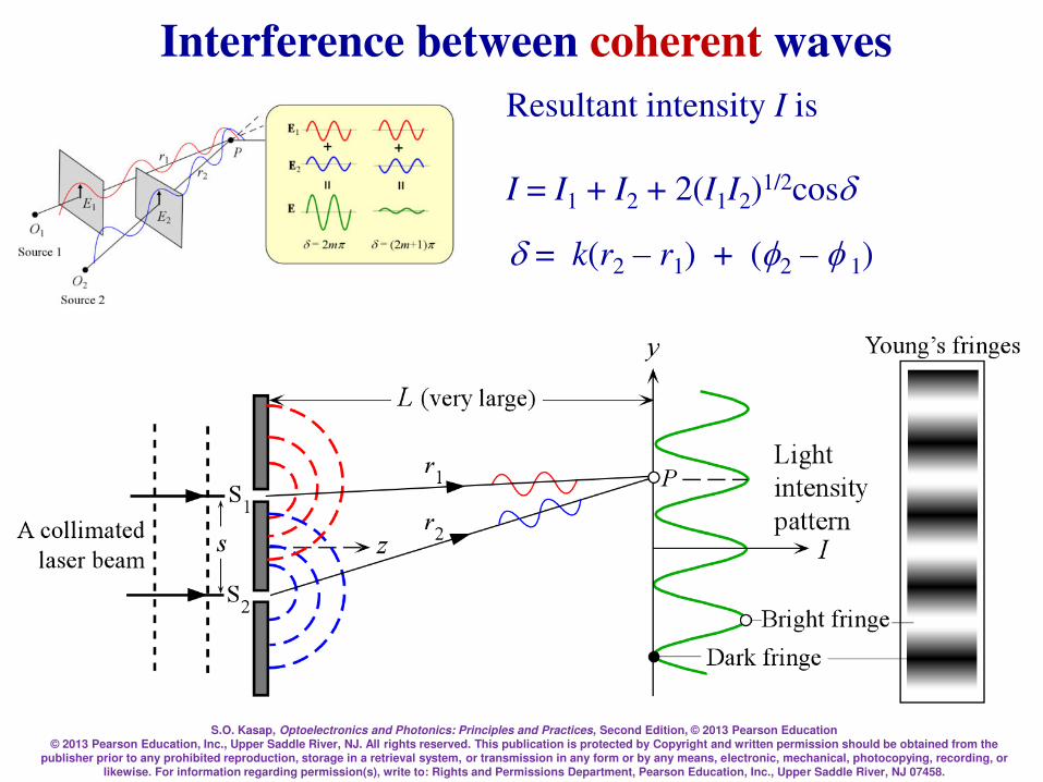
S.O. Kasap, Optoelectronics and Photonics: Principles and Practices, Second Edition, © 2013 Pearson Education © 2013 Pearson Education, Inc., Upper Saddle River, NJ. All rights reserved. This publication is protected by Copyright and written permission should be obtained from the
publisher prior to any prohibited reproduction, storage in a retrieval system, or transmission in any form or by any means, electronic, mechanical, photocopying, recording, or likewise. For information regarding permission(s), write to: Rights and Permissions Department, Pearson Education, Inc., Upper Saddle River, NJ 07458.
Interference between coherent waves
Resultant intensity I is
I = I1 + I2 + 2(I1I2)1/2cos
= k(r2 – r1) + (2 – 1)
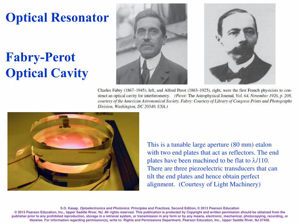
S.O. Kasap, Optoelectronics and Photonics: Principles and Practices, Second Edition, © 2013 Pearson Education © 2013 Pearson Education, Inc., Upper Saddle River, NJ. All rights reserved. This publication is protected by Copyright and written permission should be obtained from the
publisher prior to any prohibited reproduction, storage in a retrieval system, or transmission in any form or by any means, electronic, mechanical, photocopying, recording, or likewise. For information regarding permission(s), write to: Rights and Permissions Department, Pearson Education, Inc., Upper Saddle River, NJ 07458.
Optical Resonator
Fabry-Perot
Optical Cavity
This is a tunable large aperture (80 mm) etalon
with two end plates that act as reflectors. The end
plates have been machined to be flat to /110.
There are three piezoelectric transducers that can
tilt the end plates and hence obtain perfect
alignment. (Courtesy of Light Machinery)

S.O. Kasap, Optoelectronics and Photonics: Principles and Practices, Second Edition, © 2013 Pearson Education © 2013 Pearson Education, Inc., Upper Saddle River, NJ. All rights reserved. This publication is protected by Copyright and written permission should be obtained from the
publisher prior to any prohibited reproduction, storage in a retrieval system, or transmission in any form or by any means, electronic, mechanical, photocopying, recording, or likewise. For information regarding permission(s), write to: Rights and Permissions Department, Pearson Education, Inc., Upper Saddle River, NJ 07458.
Optical Resonator
Fabry-Perot Optical Cavity
Schematic illustration of the Fabry-Perot optical cavity and its properties. (a)
Reflected waves interfere. (b) Only standing EM waves, modes, of certain
wavelengths are allowed in the cavity. (c) Intensity vs. frequency for various modes.
R is mirror reflectance and lower R means higher loss from the cavity.
Note: The two curves are sketched so that the maximum intensity is unity
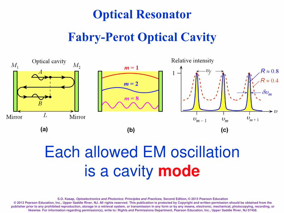
S.O. Kasap, Optoelectronics and Photonics: Principles and Practices, Second Edition, © 2013 Pearson Education © 2013 Pearson Education, Inc., Upper Saddle River, NJ. All rights reserved. This publication is protected by Copyright and written permission should be obtained from the
publisher prior to any prohibited reproduction, storage in a retrieval system, or transmission in any form or by any means, electronic, mechanical, photocopying, recording, or likewise. For information regarding permission(s), write to: Rights and Permissions Department, Pearson Education, Inc., Upper Saddle River, NJ 07458.
Each allowed EM oscillation
is a cavity mode
Optical Resonator
Fabry-Perot Optical Cavity

S.O. Kasap, Optoelectronics and Photonics: Principles and Practices, Second Edition, © 2013 Pearson Education © 2013 Pearson Education, Inc., Upper Saddle River, NJ. All rights reserved. This publication is protected by Copyright and written permission should be obtained from the
publisher prior to any prohibited reproduction, storage in a retrieval system, or transmission in any form or by any means, electronic, mechanical, photocopying, recording, or likewise. For information regarding permission(s), write to: Rights and Permissions Department, Pearson Education, Inc., Upper Saddle River, NJ 07458.
Optical Resonator Fabry-Perot
Optical Cavity
A + B = A + Ar 2exp(j2kL)
Ecavity = A + B + = A + Ar2exp(j2kL) + Ar4exp(j4kL) + Ar6exp(j6kL) +
Maxima at kmL = m
)2exp(1 2cavitykLj
AE
=
r
)(sin4)1( 22cavitykL
II o
RR =
2max)1( R
= oII
m = 1,2,3,…integer

S.O. Kasap, Optoelectronics and Photonics: Principles and Practices, Second Edition, © 2013 Pearson Education © 2013 Pearson Education, Inc., Upper Saddle River, NJ. All rights reserved. This publication is protected by Copyright and written permission should be obtained from the
publisher prior to any prohibited reproduction, storage in a retrieval system, or transmission in any form or by any means, electronic, mechanical, photocopying, recording, or likewise. For information regarding permission(s), write to: Rights and Permissions Department, Pearson Education, Inc., Upper Saddle River, NJ 07458.
Optical Resonator Fabry-Perot Optical Cavity
Maxima at kmL = m
)(sin4)1( 22cavitykL
II o
RR =
2max)1( R
= oII
m = 1,2,3,…integer
m(m/2) = L
(2/m)L = m

S.O. Kasap, Optoelectronics and Photonics: Principles and Practices, Second Edition, © 2013 Pearson Education © 2013 Pearson Education, Inc., Upper Saddle River, NJ. All rights reserved. This publication is protected by Copyright and written permission should be obtained from the
publisher prior to any prohibited reproduction, storage in a retrieval system, or transmission in any form or by any means, electronic, mechanical, photocopying, recording, or likewise. For information regarding permission(s), write to: Rights and Permissions Department, Pearson Education, Inc., Upper Saddle River, NJ 07458.
um = m(c/2L) = muf = Mode frequency
m = integer, 1,2,…
uf =free spectral range = c/2L = Separation of modes
um =u f
F
F =R1/ 2
1R
F = Finesse
R = Reflectance
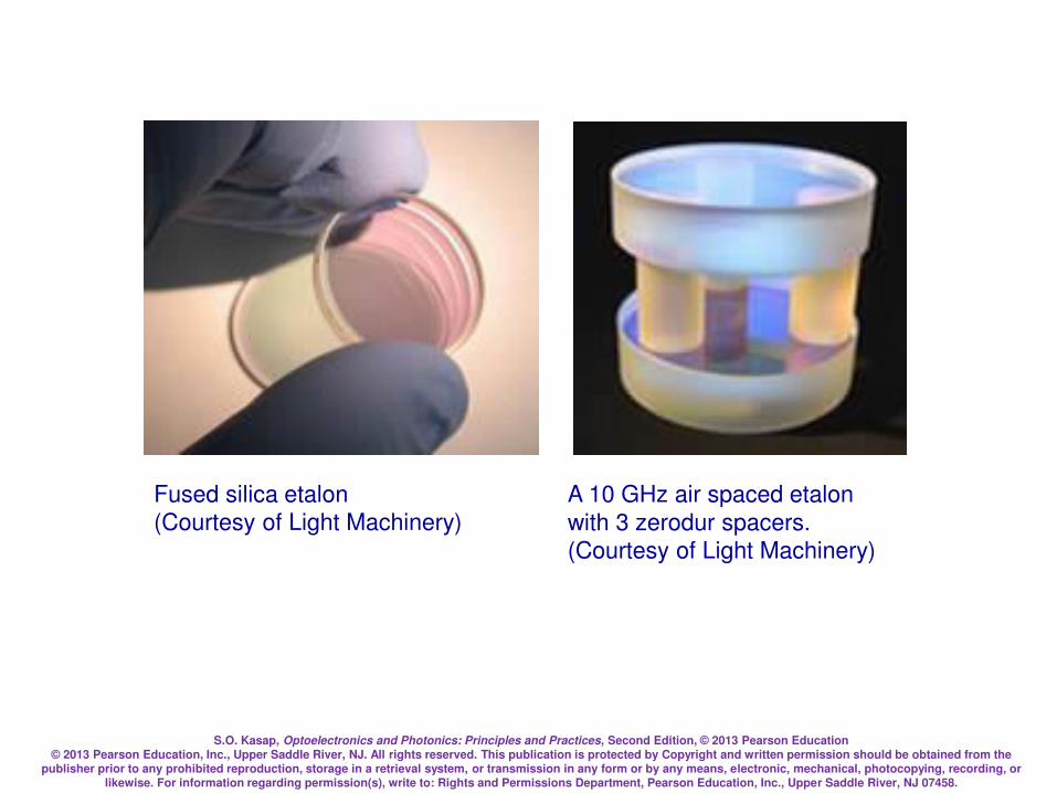
S.O. Kasap, Optoelectronics and Photonics: Principles and Practices, Second Edition, © 2013 Pearson Education © 2013 Pearson Education, Inc., Upper Saddle River, NJ. All rights reserved. This publication is protected by Copyright and written permission should be obtained from the
publisher prior to any prohibited reproduction, storage in a retrieval system, or transmission in any form or by any means, electronic, mechanical, photocopying, recording, or likewise. For information regarding permission(s), write to: Rights and Permissions Department, Pearson Education, Inc., Upper Saddle River, NJ 07458.
Fused silica etalon (Courtesy of Light Machinery)
A 10 GHz air spaced etalon
with 3 zerodur spacers. (Courtesy of Light Machinery)
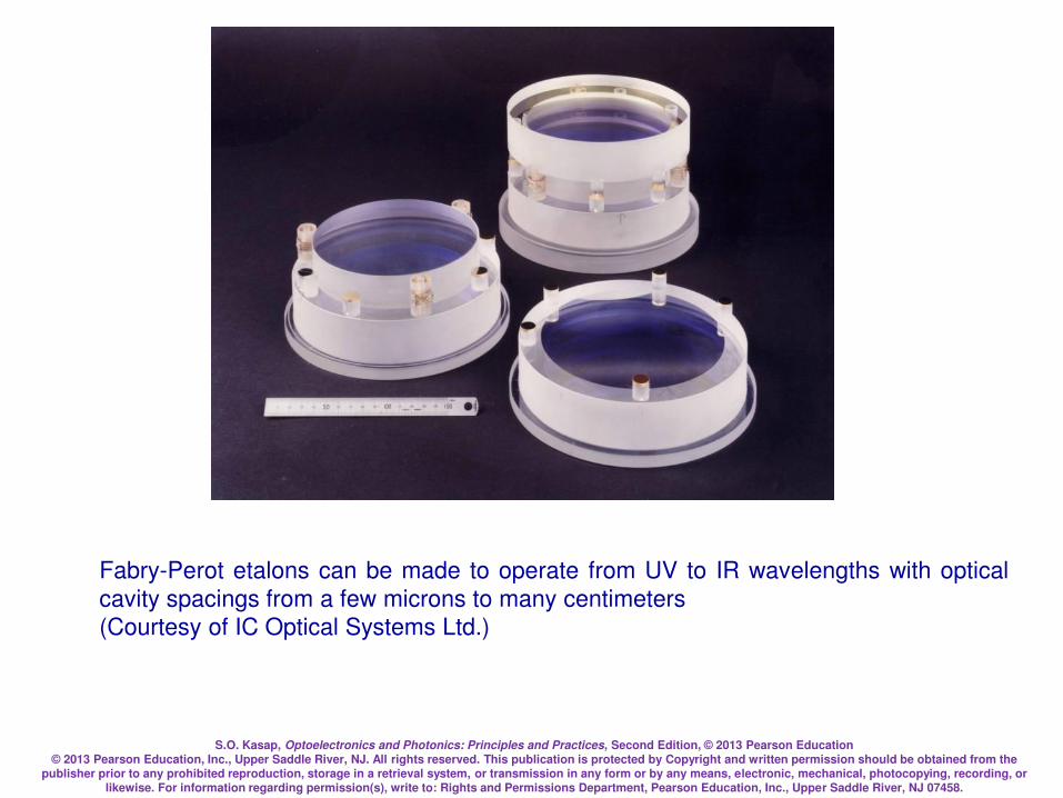
S.O. Kasap, Optoelectronics and Photonics: Principles and Practices, Second Edition, © 2013 Pearson Education © 2013 Pearson Education, Inc., Upper Saddle River, NJ. All rights reserved. This publication is protected by Copyright and written permission should be obtained from the
publisher prior to any prohibited reproduction, storage in a retrieval system, or transmission in any form or by any means, electronic, mechanical, photocopying, recording, or likewise. For information regarding permission(s), write to: Rights and Permissions Department, Pearson Education, Inc., Upper Saddle River, NJ 07458.
Fabry-Perot etalons can be made to operate from UV to IR wavelengths with optical
cavity spacings from a few microns to many centimeters (Courtesy of IC Optical Systems Ltd.)

S.O. Kasap, Optoelectronics and Photonics: Principles and Practices, Second Edition, © 2013 Pearson Education © 2013 Pearson Education, Inc., Upper Saddle River, NJ. All rights reserved. This publication is protected by Copyright and written permission should be obtained from the
publisher prior to any prohibited reproduction, storage in a retrieval system, or transmission in any form or by any means, electronic, mechanical, photocopying, recording, or likewise. For information regarding permission(s), write to: Rights and Permissions Department, Pearson Education, Inc., Upper Saddle River, NJ 07458.
Quality factor Q is similar to the Finesse F
mFQm
m ===uu
widthSpectral
frequencyResonant

S.O. Kasap, Optoelectronics and Photonics: Principles and Practices, Second Edition, © 2013 Pearson Education © 2013 Pearson Education, Inc., Upper Saddle River, NJ. All rights reserved. This publication is protected by Copyright and written permission should be obtained from the
publisher prior to any prohibited reproduction, storage in a retrieval system, or transmission in any form or by any means, electronic, mechanical, photocopying, recording, or likewise. For information regarding permission(s), write to: Rights and Permissions Department, Pearson Education, Inc., Upper Saddle River, NJ 07458.
Optical Resonator is also an optical filter
Only certain wavelengths (cavity modes) are transmitted
)(sin4)1(
)1(22
2
incidentdtransmittekL
IIRR
R
=
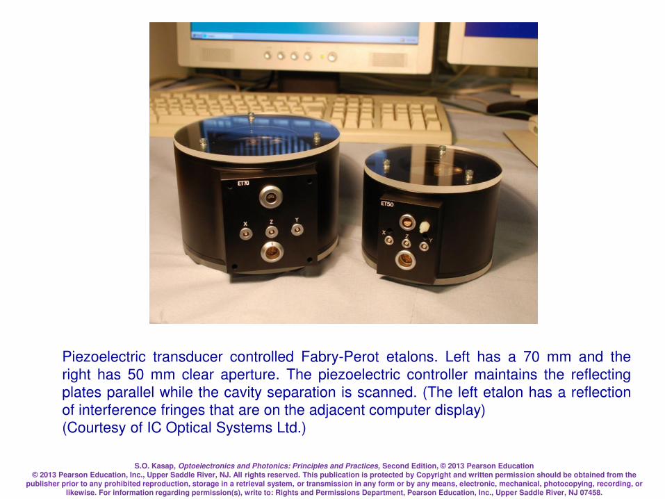
S.O. Kasap, Optoelectronics and Photonics: Principles and Practices, Second Edition, © 2013 Pearson Education © 2013 Pearson Education, Inc., Upper Saddle River, NJ. All rights reserved. This publication is protected by Copyright and written permission should be obtained from the
publisher prior to any prohibited reproduction, storage in a retrieval system, or transmission in any form or by any means, electronic, mechanical, photocopying, recording, or likewise. For information regarding permission(s), write to: Rights and Permissions Department, Pearson Education, Inc., Upper Saddle River, NJ 07458.
Piezoelectric transducer controlled Fabry-Perot etalons. Left has a 70 mm and the
right has 50 mm clear aperture. The piezoelectric controller maintains the reflecting
plates parallel while the cavity separation is scanned. (The left etalon has a reflection
of interference fringes that are on the adjacent computer display) (Courtesy of IC Optical Systems Ltd.)
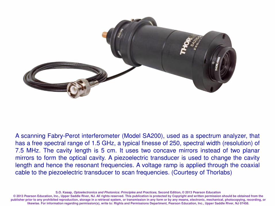
S.O. Kasap, Optoelectronics and Photonics: Principles and Practices, Second Edition, © 2013 Pearson Education © 2013 Pearson Education, Inc., Upper Saddle River, NJ. All rights reserved. This publication is protected by Copyright and written permission should be obtained from the
publisher prior to any prohibited reproduction, storage in a retrieval system, or transmission in any form or by any means, electronic, mechanical, photocopying, recording, or likewise. For information regarding permission(s), write to: Rights and Permissions Department, Pearson Education, Inc., Upper Saddle River, NJ 07458.
A scanning Fabry-Perot interferometer (Model SA200), used as a spectrum analyzer, that
has a free spectral range of 1.5 GHz, a typical finesse of 250, spectral width (resolution) of
7.5 MHz. The cavity length is 5 cm. It uses two concave mirrors instead of two planar
mirrors to form the optical cavity. A piezoelectric transducer is used to change the cavity
length and hence the resonant frequencies. A voltage ramp is applied through the coaxial cable to the piezoelectric transducer to scan frequencies. (Courtesy of Thorlabs)

S.O. Kasap, Optoelectronics and Photonics: Principles and Practices, Second Edition, © 2013 Pearson Education © 2013 Pearson Education, Inc., Upper Saddle River, NJ. All rights reserved. This publication is protected by Copyright and written permission should be obtained from the
publisher prior to any prohibited reproduction, storage in a retrieval system, or transmission in any form or by any means, electronic, mechanical, photocopying, recording, or likewise. For information regarding permission(s), write to: Rights and Permissions Department, Pearson Education, Inc., Upper Saddle River, NJ 07458.
Example: An Optical Resonator in Air
Consider a Fabry-Perot optical cavity in air of length 100 microns with mirrors that have
a reflectance of 0.90. Calculate the cavity mode nearest to the wavelength 900 nm, and
corresponding wavelength. Calculate the separation of the modes, the finesse, the
spectral width of each mode and the Q-factor
Thus, m = 222 (must be an integer)
m = 900.90 nm 900 nm (very close)
Solution
2.222)10900(
)10100(229
6
=
==
L
m nm9.900)222(
)10100(22 6
=
==
m
Lm
The frequency corresponding to m is
um = c/m = (3108)/(900.910-9) = 3.331014 Hz
Find the mode number m corresponding to 900 nm and then
take the integer
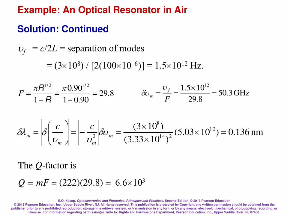
S.O. Kasap, Optoelectronics and Photonics: Principles and Practices, Second Edition, © 2013 Pearson Education © 2013 Pearson Education, Inc., Upper Saddle River, NJ. All rights reserved. This publication is protected by Copyright and written permission should be obtained from the
publisher prior to any prohibited reproduction, storage in a retrieval system, or transmission in any form or by any means, electronic, mechanical, photocopying, recording, or likewise. For information regarding permission(s), write to: Rights and Permissions Department, Pearson Education, Inc., Upper Saddle River, NJ 07458.
Example: An Optical Resonator in Air
uf = c/2L = separation of modes
= (3108) / [2(100106)] = 1.51012 Hz.
8.2990.01
90.0
1
2/12/1
=
=
=
R
RF GHz 3.50
8.29
105.1 12
=
==F
f
m
uu
nm 136.0)1003.5()1033.3(
)103( 10
214
8
2=
==
= m
mm
m
cc uuu
Solution: Continued
The Q-factor is
Q = mF = (222)(29.8) = 6.6103

S.O. Kasap, Optoelectronics and Photonics: Principles and Practices, Second Edition, © 2013 Pearson Education © 2013 Pearson Education, Inc., Upper Saddle River, NJ. All rights reserved. This publication is protected by Copyright and written permission should be obtained from the
publisher prior to any prohibited reproduction, storage in a retrieval system, or transmission in any form or by any means, electronic, mechanical, photocopying, recording, or likewise. For information regarding permission(s), write to: Rights and Permissions Department, Pearson Education, Inc., Upper Saddle River, NJ 07458.
Example: Semiconductor Optical Cavity
Consider a Fabry-Perot optical cavity of a semiconductor material of length 250 microns
with mirrors, each with a reflectance of 0.90. Calculate the cavity mode nearest to 1310
nm. Calculate the separation of the modes, finesse, the spectral width of each mode, and
the Q-factor. Take n = 3.6 for the semiconductor medium.
Given, L=250106 m, n = 3.6, R = 0.90
um=uf = c/2nL = Separation of modes = 1.671011 Hz
F =R1/2
1R=0.9
1/2
10.9= 29.8
GHz 59.58.29
1067.1 11
=
==F
f
m
uu
Solution

S.O. Kasap, Optoelectronics and Photonics: Principles and Practices, Second Edition, © 2013 Pearson Education © 2013 Pearson Education, Inc., Upper Saddle River, NJ. All rights reserved. This publication is protected by Copyright and written permission should be obtained from the
publisher prior to any prohibited reproduction, storage in a retrieval system, or transmission in any form or by any means, electronic, mechanical, photocopying, recording, or likewise. For information regarding permission(s), write to: Rights and Permissions Department, Pearson Education, Inc., Upper Saddle River, NJ 07458.
05.1374)101310(
)10250)(6.3(229
6
=
==
nL
m
Mode number m corresponding to 1310 nm is
which must be an integer (1374) so that the actual mode
wavelength is
nm04.1310)1374(
)10250)(6.3(22 6
=
==
m
nLm
For all practical purposes the mode wavelength is 1310 nm
Mode frequency is
Hz103.2)101310(
)103( 14
9
8
=
== m
m
c
u
Solution: Continued
Example: Semiconductor Optical Cavity

S.O. Kasap, Optoelectronics and Photonics: Principles and Practices, Second Edition, © 2013 Pearson Education © 2013 Pearson Education, Inc., Upper Saddle River, NJ. All rights reserved. This publication is protected by Copyright and written permission should be obtained from the
publisher prior to any prohibited reproduction, storage in a retrieval system, or transmission in any form or by any means, electronic, mechanical, photocopying, recording, or likewise. For information regarding permission(s), write to: Rights and Permissions Department, Pearson Education, Inc., Upper Saddle River, NJ 07458.
nm 136.0)1003.5()1033.3(
)103( 10
214
8
2=
==
= m
mm
m
cc uuu
Spectral width of a mode in wavelength is
The Q-factor is
Q = mF = (1374)(29.8) = .110
Solution: Continued
Example: Semiconductor Optical Cavity
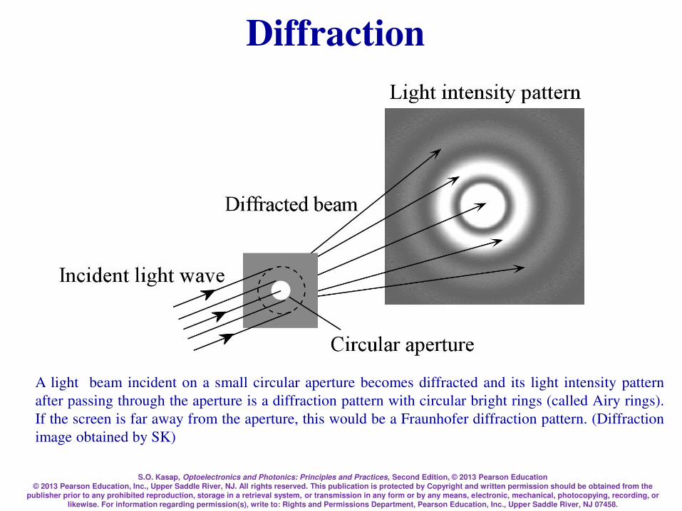
S.O. Kasap, Optoelectronics and Photonics: Principles and Practices, Second Edition, © 2013 Pearson Education © 2013 Pearson Education, Inc., Upper Saddle River, NJ. All rights reserved. This publication is protected by Copyright and written permission should be obtained from the
publisher prior to any prohibited reproduction, storage in a retrieval system, or transmission in any form or by any means, electronic, mechanical, photocopying, recording, or likewise. For information regarding permission(s), write to: Rights and Permissions Department, Pearson Education, Inc., Upper Saddle River, NJ 07458.
Diffraction
A light beam incident on a small circular aperture becomes diffracted and its light intensity pattern
after passing through the aperture is a diffraction pattern with circular bright rings (called Airy rings).
If the screen is far away from the aperture, this would be a Fraunhofer diffraction pattern. (Diffraction
image obtained by SK)
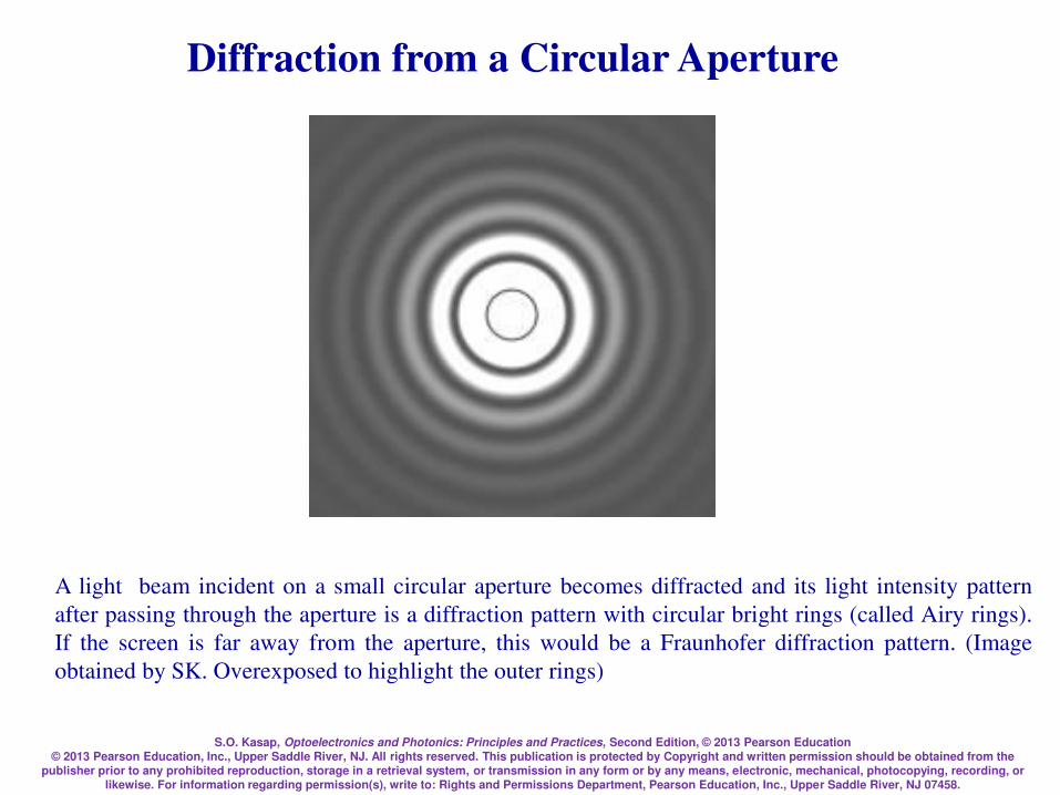
S.O. Kasap, Optoelectronics and Photonics: Principles and Practices, Second Edition, © 2013 Pearson Education © 2013 Pearson Education, Inc., Upper Saddle River, NJ. All rights reserved. This publication is protected by Copyright and written permission should be obtained from the
publisher prior to any prohibited reproduction, storage in a retrieval system, or transmission in any form or by any means, electronic, mechanical, photocopying, recording, or likewise. For information regarding permission(s), write to: Rights and Permissions Department, Pearson Education, Inc., Upper Saddle River, NJ 07458.
A light beam incident on a small circular aperture becomes diffracted and its light intensity pattern
after passing through the aperture is a diffraction pattern with circular bright rings (called Airy rings).
If the screen is far away from the aperture, this would be a Fraunhofer diffraction pattern. (Image
obtained by SK. Overexposed to highlight the outer rings)
Diffraction from a Circular Aperture
S.O. Kasap, Optoelectronics and Photonics: Principles and Practices, Second Edition, © 2013 Pearson Education © 2013 Pearson Education, Inc., Upper Saddle River, NJ. All rights reserved. This publication is protected by Copyright and written permission should be obtained from the
publisher prior to any prohibited reproduction, storage in a retrieval system, or transmission in any form or by any means, electronic, mechanical, photocopying, recording, or likewise. For information regarding permission(s), write to: Rights and Permissions Department, Pearson Education, Inc., Upper Saddle River, NJ 07458.
Diffraction
Huygens-Fresnel principle
Every unobstructed point of a wavefront, at a given
instant in time, serves as a source of spherical
secondary waves (with the same frequency as that of
the primary wave). The amplitude of the optical field at
any point beyond is the superposition of all these
wavelets (considering their amplitudes and relative
phases)
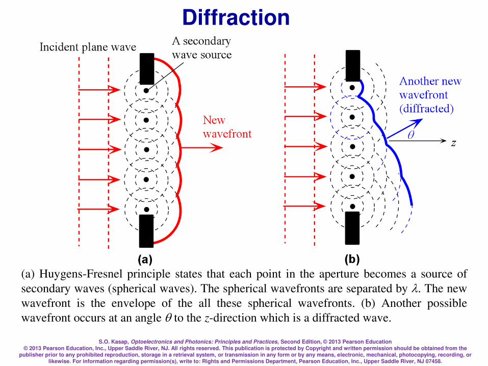
S.O. Kasap, Optoelectronics and Photonics: Principles and Practices, Second Edition, © 2013 Pearson Education © 2013 Pearson Education, Inc., Upper Saddle River, NJ. All rights reserved. This publication is protected by Copyright and written permission should be obtained from the
publisher prior to any prohibited reproduction, storage in a retrieval system, or transmission in any form or by any means, electronic, mechanical, photocopying, recording, or likewise. For information regarding permission(s), write to: Rights and Permissions Department, Pearson Education, Inc., Upper Saddle River, NJ 07458.
Diffraction
(a) Huygens-Fresnel principle states that each point in the aperture becomes a source of
secondary waves (spherical waves). The spherical wavefronts are separated by . The new
wavefront is the envelope of the all these spherical wavefronts. (b) Another possible
wavefront occurs at an angle q to the z-direction which is a diffracted wave.
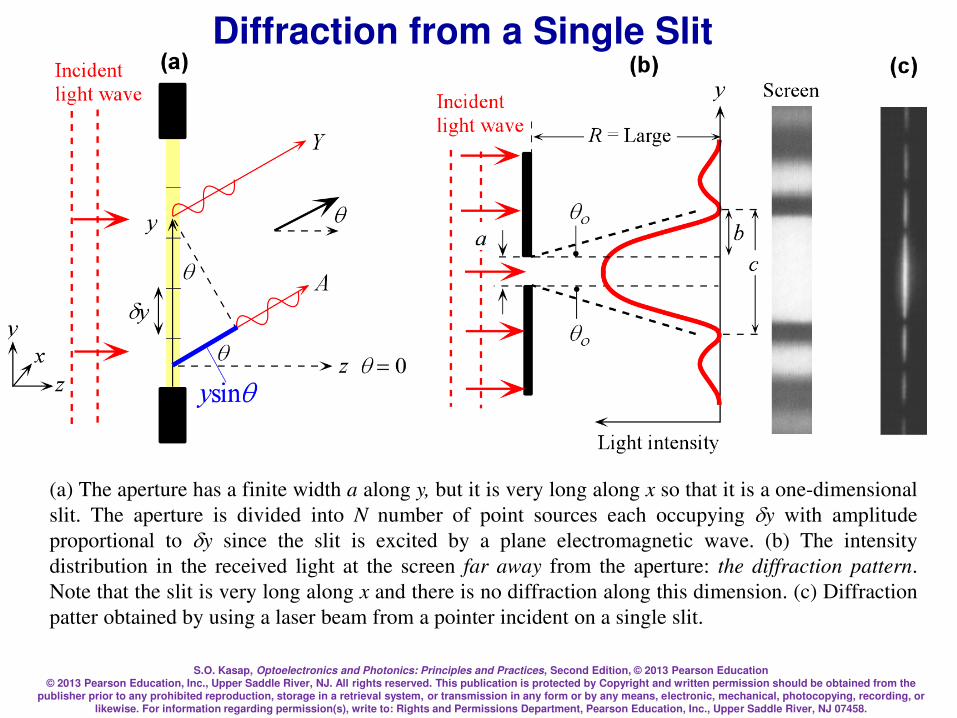
S.O. Kasap, Optoelectronics and Photonics: Principles and Practices, Second Edition, © 2013 Pearson Education © 2013 Pearson Education, Inc., Upper Saddle River, NJ. All rights reserved. This publication is protected by Copyright and written permission should be obtained from the
publisher prior to any prohibited reproduction, storage in a retrieval system, or transmission in any form or by any means, electronic, mechanical, photocopying, recording, or likewise. For information regarding permission(s), write to: Rights and Permissions Department, Pearson Education, Inc., Upper Saddle River, NJ 07458.
(a) The aperture has a finite width a along y, but it is very long along x so that it is a one-dimensional
slit. The aperture is divided into N number of point sources each occupying y with amplitude
proportional to y since the slit is excited by a plane electromagnetic wave. (b) The intensity
distribution in the received light at the screen far away from the aperture: the diffraction pattern.
Note that the slit is very long along x and there is no diffraction along this dimension. (c) Diffraction
patter obtained by using a laser beam from a pointer incident on a single slit.
Diffraction from a Single Slit

S.O. Kasap, Optoelectronics and Photonics: Principles and Practices, Second Edition, © 2013 Pearson Education © 2013 Pearson Education, Inc., Upper Saddle River, NJ. All rights reserved. This publication is protected by Copyright and written permission should be obtained from the
publisher prior to any prohibited reproduction, storage in a retrieval system, or transmission in any form or by any means, electronic, mechanical, photocopying, recording, or likewise. For information regarding permission(s), write to: Rights and Permissions Department, Pearson Education, Inc., Upper Saddle River, NJ 07458.
Diffraction from a Single Slit
)sinexp()( q jkyyE
=
=
=ay
y
jkyyCE0
)sinexp()( qq
sin
)sinsin()(
2
1
2
1sin2
1
ka
kaaCE
kaj
=e
)(sinc)0(sin
)sinsin()( 2
2
2
1
2
1
q
qq I
ka
kaaCI =
=
q sin2
1ka=

S.O. Kasap, Optoelectronics and Photonics: Principles and Practices, Second Edition, © 2013 Pearson Education © 2013 Pearson Education, Inc., Upper Saddle River, NJ. All rights reserved. This publication is protected by Copyright and written permission should be obtained from the
publisher prior to any prohibited reproduction, storage in a retrieval system, or transmission in any form or by any means, electronic, mechanical, photocopying, recording, or likewise. For information regarding permission(s), write to: Rights and Permissions Department, Pearson Education, Inc., Upper Saddle River, NJ 07458.
)(sinc)0(sin
)0(sin
)sinsin()0()( 2
22
2
1
2
1
q IIka
kaII =
=
=
q sin2
1ka=
Zero intensity when I(q) = 0
a
mq =sin
Divergence
Diffraction from a Single Slit
ao
qq 22 =

S.O. Kasap, Optoelectronics and Photonics: Principles and Practices, Second Edition, © 2013 Pearson Education © 2013 Pearson Education, Inc., Upper Saddle River, NJ. All rights reserved. This publication is protected by Copyright and written permission should be obtained from the
publisher prior to any prohibited reproduction, storage in a retrieval system, or transmission in any form or by any means, electronic, mechanical, photocopying, recording, or likewise. For information regarding permission(s), write to: Rights and Permissions Department, Pearson Education, Inc., Upper Saddle River, NJ 07458.
Diffraction from a Circular Aperture
Do
q 22.1sin = Diameter of
aperture
(Image obtained by SK)

S.O. Kasap, Optoelectronics and Photonics: Principles and Practices, Second Edition, © 2013 Pearson Education © 2013 Pearson Education, Inc., Upper Saddle River, NJ. All rights reserved. This publication is protected by Copyright and written permission should be obtained from the
publisher prior to any prohibited reproduction, storage in a retrieval system, or transmission in any form or by any means, electronic, mechanical, photocopying, recording, or likewise. For information regarding permission(s), write to: Rights and Permissions Department, Pearson Education, Inc., Upper Saddle River, NJ 07458.
a
b
The rectangular aperture of dimensions a × b on the left gives the
diffraction pattern on the right. (b is twice a)
(Image obtained by SK. Overexposed to highlight the higher order lobes.)
Diffraction from a Rectangular Aperture
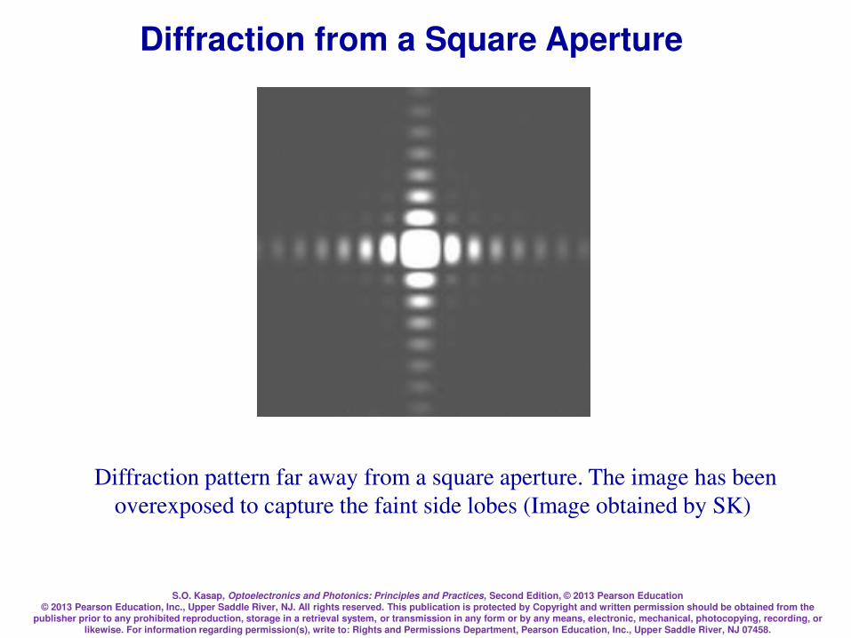
S.O. Kasap, Optoelectronics and Photonics: Principles and Practices, Second Edition, © 2013 Pearson Education © 2013 Pearson Education, Inc., Upper Saddle River, NJ. All rights reserved. This publication is protected by Copyright and written permission should be obtained from the
publisher prior to any prohibited reproduction, storage in a retrieval system, or transmission in any form or by any means, electronic, mechanical, photocopying, recording, or likewise. For information regarding permission(s), write to: Rights and Permissions Department, Pearson Education, Inc., Upper Saddle River, NJ 07458.
Diffraction pattern far away from a square aperture. The image has been
overexposed to capture the faint side lobes (Image obtained by SK)
Diffraction from a Square Aperture
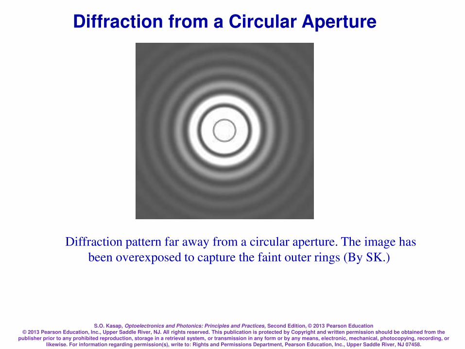
S.O. Kasap, Optoelectronics and Photonics: Principles and Practices, Second Edition, © 2013 Pearson Education © 2013 Pearson Education, Inc., Upper Saddle River, NJ. All rights reserved. This publication is protected by Copyright and written permission should be obtained from the
publisher prior to any prohibited reproduction, storage in a retrieval system, or transmission in any form or by any means, electronic, mechanical, photocopying, recording, or likewise. For information regarding permission(s), write to: Rights and Permissions Department, Pearson Education, Inc., Upper Saddle River, NJ 07458.
Diffraction pattern far away from a circular aperture. The image has
been overexposed to capture the faint outer rings (By SK.)
Diffraction from a Circular Aperture

S.O. Kasap, Optoelectronics and Photonics: Principles and Practices, Second Edition, © 2013 Pearson Education © 2013 Pearson Education, Inc., Upper Saddle River, NJ. All rights reserved. This publication is protected by Copyright and written permission should be obtained from the
publisher prior to any prohibited reproduction, storage in a retrieval system, or transmission in any form or by any means, electronic, mechanical, photocopying, recording, or likewise. For information regarding permission(s), write to: Rights and Permissions Department, Pearson Education, Inc., Upper Saddle River, NJ 07458.
Diffraction from a Circular Aperture
George Bidell Airy (1801–1892, England).
George Airy was a professor of astronomy
at Cambridge and then the Astronomer
Royal at the Royal Observatory in
Greenwich, England. (© Mary Evans
Picture Library/Alamy.)
2
1 )(2)(
=
J
II o
= (1/2)kDsinq
k = 2
dJ )sincos(1
)(0
1 =
Bessel function (first kind,
first order)
Intensity distribution
(By SK)
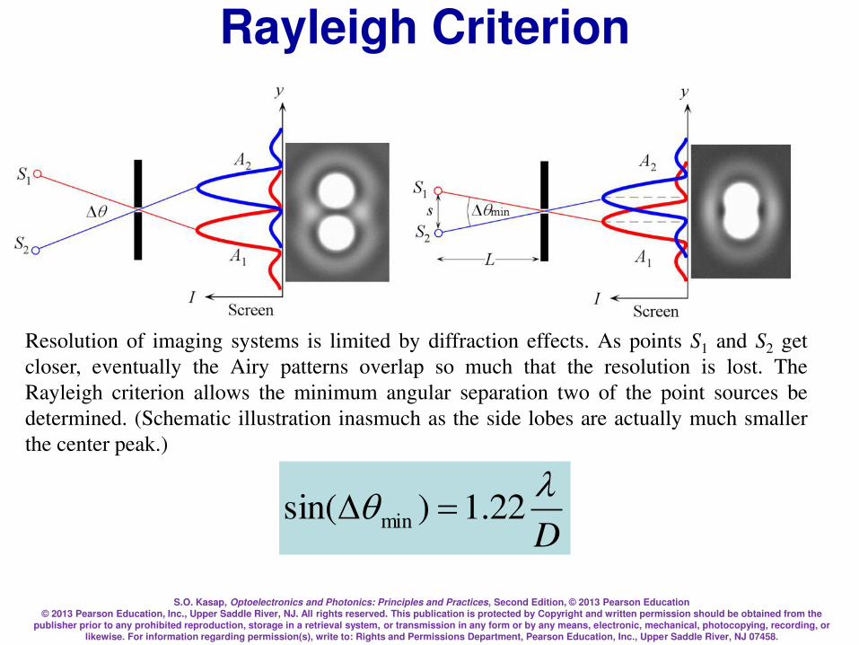
S.O. Kasap, Optoelectronics and Photonics: Principles and Practices, Second Edition, © 2013 Pearson Education © 2013 Pearson Education, Inc., Upper Saddle River, NJ. All rights reserved. This publication is protected by Copyright and written permission should be obtained from the
publisher prior to any prohibited reproduction, storage in a retrieval system, or transmission in any form or by any means, electronic, mechanical, photocopying, recording, or likewise. For information regarding permission(s), write to: Rights and Permissions Department, Pearson Education, Inc., Upper Saddle River, NJ 07458.
Rayleigh Criterion
Resolution of imaging systems is limited by diffraction effects. As points S1 and S2 get
closer, eventually the Airy patterns overlap so much that the resolution is lost. The
Rayleigh criterion allows the minimum angular separation two of the point sources be
determined. (Schematic illustration inasmuch as the side lobes are actually much smaller
the center peak.)
D
q 22.1)sin( min =
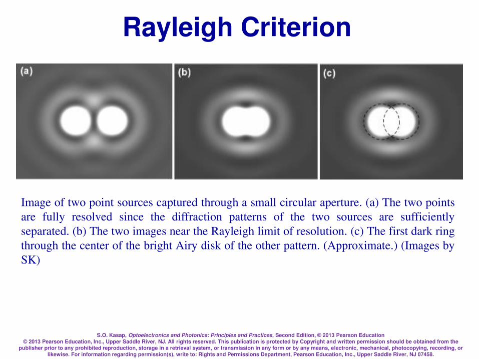
S.O. Kasap, Optoelectronics and Photonics: Principles and Practices, Second Edition, © 2013 Pearson Education © 2013 Pearson Education, Inc., Upper Saddle River, NJ. All rights reserved. This publication is protected by Copyright and written permission should be obtained from the
publisher prior to any prohibited reproduction, storage in a retrieval system, or transmission in any form or by any means, electronic, mechanical, photocopying, recording, or likewise. For information regarding permission(s), write to: Rights and Permissions Department, Pearson Education, Inc., Upper Saddle River, NJ 07458.
Rayleigh Criterion
Image of two point sources captured through a small circular aperture. (a) The two points
are fully resolved since the diffraction patterns of the two sources are sufficiently
separated. (b) The two images near the Rayleigh limit of resolution. (c) The first dark ring
through the center of the bright Airy disk of the other pattern. (Approximate.) (Images by
SK)
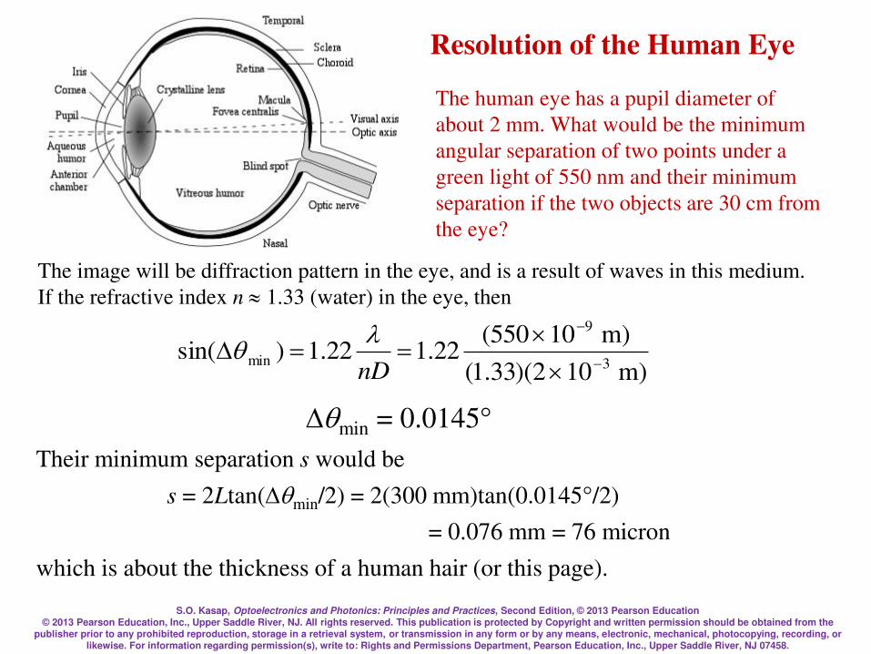
S.O. Kasap, Optoelectronics and Photonics: Principles and Practices, Second Edition, © 2013 Pearson Education © 2013 Pearson Education, Inc., Upper Saddle River, NJ. All rights reserved. This publication is protected by Copyright and written permission should be obtained from the
publisher prior to any prohibited reproduction, storage in a retrieval system, or transmission in any form or by any means, electronic, mechanical, photocopying, recording, or likewise. For information regarding permission(s), write to: Rights and Permissions Department, Pearson Education, Inc., Upper Saddle River, NJ 07458.
Resolution of the Human Eye
The human eye has a pupil diameter of
about 2 mm. What would be the minimum
angular separation of two points under a
green light of 550 nm and their minimum
separation if the two objects are 30 cm from
the eye?
The image will be diffraction pattern in the eye, and is a result of waves in this medium.
If the refractive index n 1.33 (water) in the eye, then
)m 102)(33.1(
)m 10550(22.122.1)sin(
3
9
min
==nD
q
qmin = 0.0145°
Their minimum separation s would be
s = 2Ltan(qmin/2) = 2(300 mm)tan(0.0145°/2)
= 0.076 mm = 76 micron
which is about the thickness of a human hair (or this page).
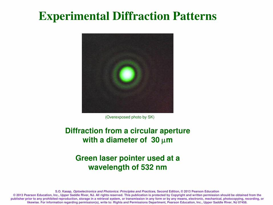
S.O. Kasap, Optoelectronics and Photonics: Principles and Practices, Second Edition, © 2013 Pearson Education © 2013 Pearson Education, Inc., Upper Saddle River, NJ. All rights reserved. This publication is protected by Copyright and written permission should be obtained from the
publisher prior to any prohibited reproduction, storage in a retrieval system, or transmission in any form or by any means, electronic, mechanical, photocopying, recording, or likewise. For information regarding permission(s), write to: Rights and Permissions Department, Pearson Education, Inc., Upper Saddle River, NJ 07458.
Diffraction from a circular aperture with a diameter of 30 m
Green laser pointer used at a
wavelength of 532 nm
Experimental Diffraction Patterns
(Overexposed photo by SK)

S.O. Kasap, Optoelectronics and Photonics: Principles and Practices, Second Edition, © 2013 Pearson Education © 2013 Pearson Education, Inc., Upper Saddle River, NJ. All rights reserved. This publication is protected by Copyright and written permission should be obtained from the
publisher prior to any prohibited reproduction, storage in a retrieval system, or transmission in any form or by any means, electronic, mechanical, photocopying, recording, or likewise. For information regarding permission(s), write to: Rights and Permissions Department, Pearson Education, Inc., Upper Saddle River, NJ 07458.
Crossed slits 200 x 100 m
Green laser pointer used at a wavelength of 532 nm
Experimental Diffraction Patterns
(Overexposed photo by SK)
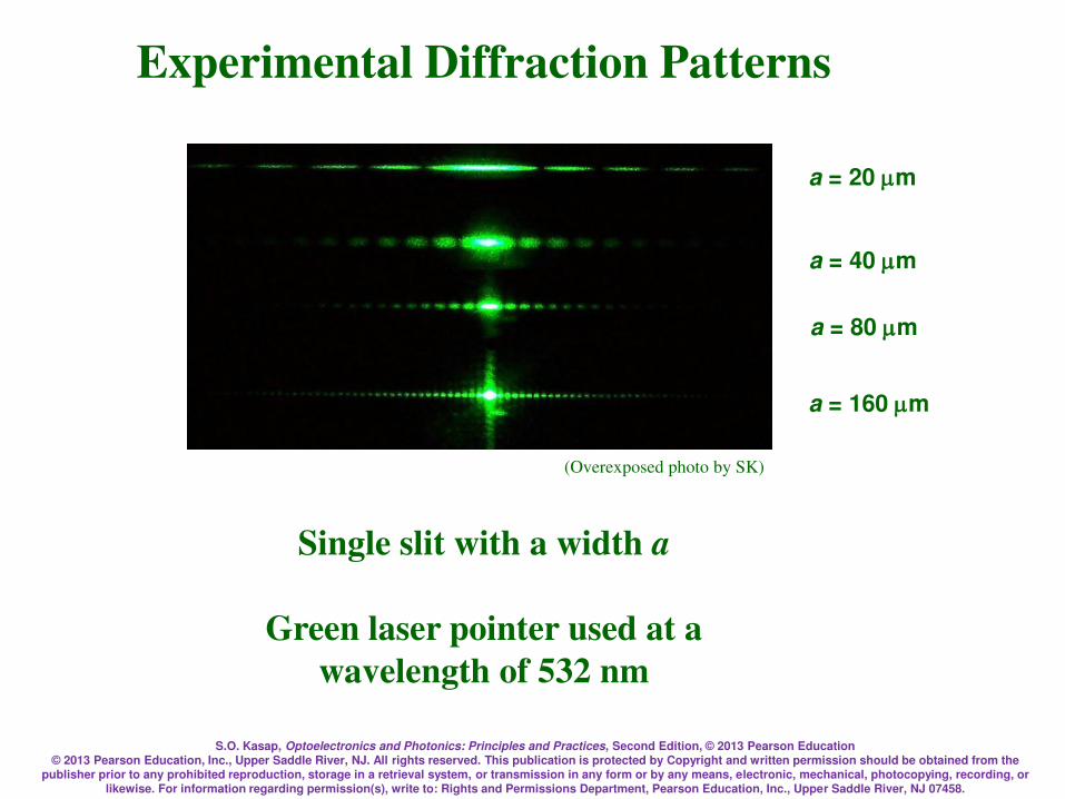
S.O. Kasap, Optoelectronics and Photonics: Principles and Practices, Second Edition, © 2013 Pearson Education © 2013 Pearson Education, Inc., Upper Saddle River, NJ. All rights reserved. This publication is protected by Copyright and written permission should be obtained from the
publisher prior to any prohibited reproduction, storage in a retrieval system, or transmission in any form or by any means, electronic, mechanical, photocopying, recording, or likewise. For information regarding permission(s), write to: Rights and Permissions Department, Pearson Education, Inc., Upper Saddle River, NJ 07458.
Experimental Diffraction Patterns
Single slit with a width a
Green laser pointer used at a
wavelength of 532 nm
a = 20 m
a = 40 m
a = 80 m
a = 160 m
(Overexposed photo by SK)
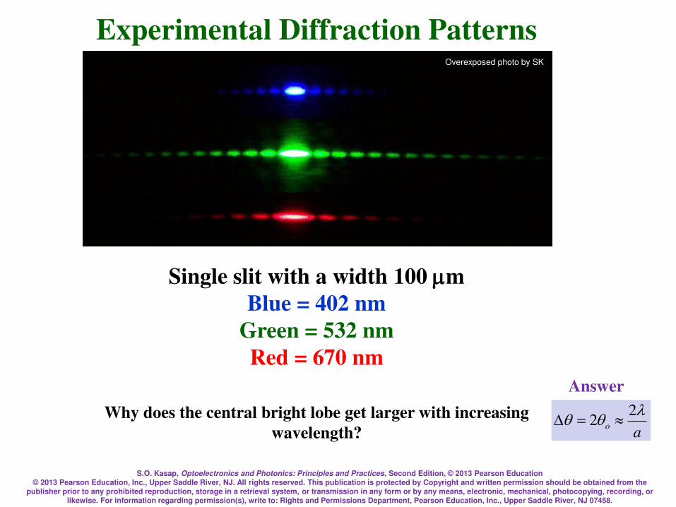
S.O. Kasap, Optoelectronics and Photonics: Principles and Practices, Second Edition, © 2013 Pearson Education © 2013 Pearson Education, Inc., Upper Saddle River, NJ. All rights reserved. This publication is protected by Copyright and written permission should be obtained from the
publisher prior to any prohibited reproduction, storage in a retrieval system, or transmission in any form or by any means, electronic, mechanical, photocopying, recording, or likewise. For information regarding permission(s), write to: Rights and Permissions Department, Pearson Education, Inc., Upper Saddle River, NJ 07458.
Single slit with a width 100 m
Blue = 402 nm
Green = 532 nm
Red = 670 nm
Why does the central bright lobe get larger with increasing
wavelength?
Overexposed photo by SK
Experimental Diffraction Patterns
ao
qq 22 =
Answer
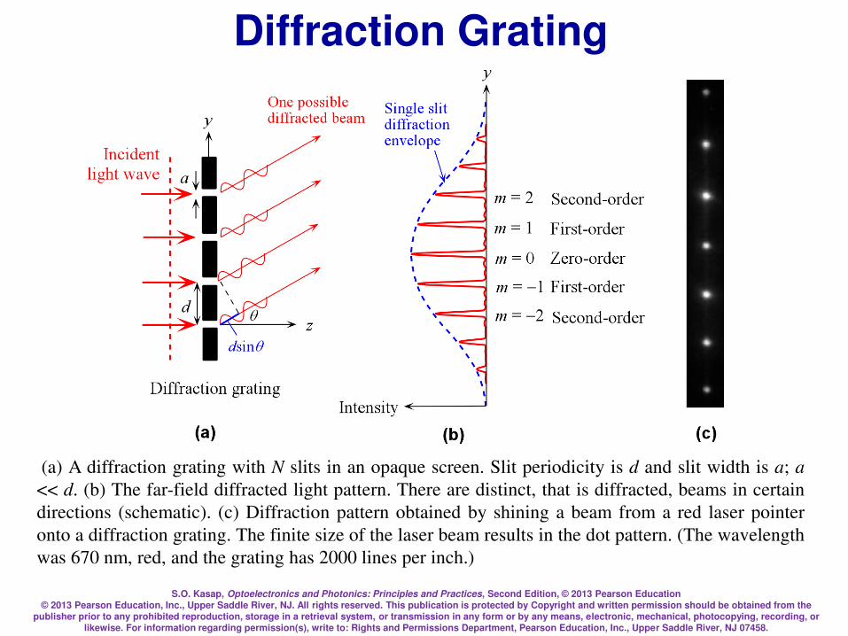
S.O. Kasap, Optoelectronics and Photonics: Principles and Practices, Second Edition, © 2013 Pearson Education © 2013 Pearson Education, Inc., Upper Saddle River, NJ. All rights reserved. This publication is protected by Copyright and written permission should be obtained from the
publisher prior to any prohibited reproduction, storage in a retrieval system, or transmission in any form or by any means, electronic, mechanical, photocopying, recording, or likewise. For information regarding permission(s), write to: Rights and Permissions Department, Pearson Education, Inc., Upper Saddle River, NJ 07458.
(a) A diffraction grating with N slits in an opaque screen. Slit periodicity is d and slit width is a; a
<< d. (b) The far-field diffracted light pattern. There are distinct, that is diffracted, beams in certain
directions (schematic). (c) Diffraction pattern obtained by shining a beam from a red laser pointer
onto a diffraction grating. The finite size of the laser beam results in the dot pattern. (The wavelength
was 670 nm, red, and the grating has 2000 lines per inch.)
Diffraction Grating

S.O. Kasap, Optoelectronics and Photonics: Principles and Practices, Second Edition, © 2013 Pearson Education © 2013 Pearson Education, Inc., Upper Saddle River, NJ. All rights reserved. This publication is protected by Copyright and written permission should be obtained from the
publisher prior to any prohibited reproduction, storage in a retrieval system, or transmission in any form or by any means, electronic, mechanical, photocopying, recording, or likewise. For information regarding permission(s), write to: Rights and Permissions Department, Pearson Education, Inc., Upper Saddle River, NJ 07458.
Diffraction Grating
dsinq = m ; m = 0, 1, 2,
Bragg diffraction condition
Normal incidence
William Lawrence Bragg (1890-1971), Australian-born British physicist, won the Nobel prize with his father William Henry Bragg for his "famous equation" when he was only 25 years old (Courtesy of SSPL via Getty Images) “The important thing in science is not so much to obtain new facts as to discover new ways of thinking about them.”

S.O. Kasap, Optoelectronics and Photonics: Principles and Practices, Second Edition, © 2013 Pearson Education © 2013 Pearson Education, Inc., Upper Saddle River, NJ. All rights reserved. This publication is protected by Copyright and written permission should be obtained from the
publisher prior to any prohibited reproduction, storage in a retrieval system, or transmission in any form or by any means, electronic, mechanical, photocopying, recording, or likewise. For information regarding permission(s), write to: Rights and Permissions Department, Pearson Education, Inc., Upper Saddle River, NJ 07458.
Diffraction Gratings
dsinq = m ; m = 0, 1, 2,
d(sinqm sinqi = m ; m = 0, 1, 2,
Bragg diffraction condition
Normal incidence
Oblique incidence
2
21
21
2
21
21
)sin(
)sin()sin()(
=
dkN
dNk
ak
akIyI
y
y
y
y
o
ky = (2/)sinq Diffraction from N slits Diffraction from a single slit
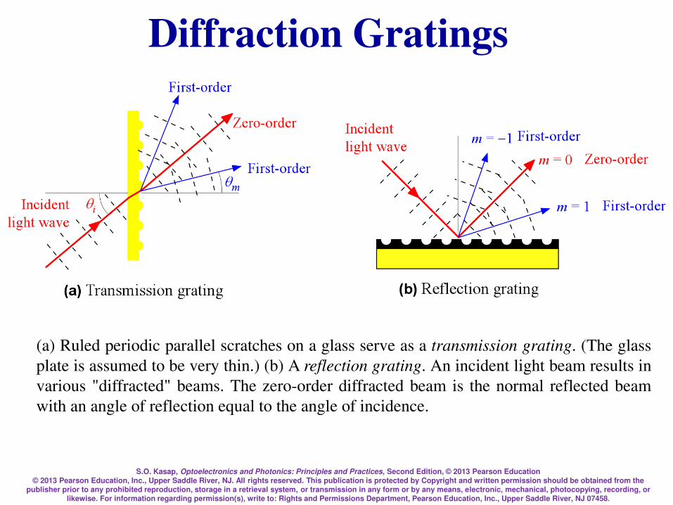
S.O. Kasap, Optoelectronics and Photonics: Principles and Practices, Second Edition, © 2013 Pearson Education © 2013 Pearson Education, Inc., Upper Saddle River, NJ. All rights reserved. This publication is protected by Copyright and written permission should be obtained from the
publisher prior to any prohibited reproduction, storage in a retrieval system, or transmission in any form or by any means, electronic, mechanical, photocopying, recording, or likewise. For information regarding permission(s), write to: Rights and Permissions Department, Pearson Education, Inc., Upper Saddle River, NJ 07458.
(a) Ruled periodic parallel scratches on a glass serve as a transmission grating. (The glass
plate is assumed to be very thin.) (b) A reflection grating. An incident light beam results in
various "diffracted" beams. The zero-order diffracted beam is the normal reflected beam
with an angle of reflection equal to the angle of incidence.
Diffraction Gratings
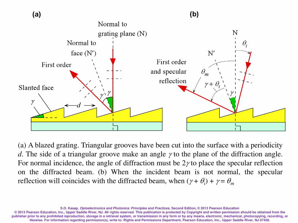
S.O. Kasap, Optoelectronics and Photonics: Principles and Practices, Second Edition, © 2013 Pearson Education © 2013 Pearson Education, Inc., Upper Saddle River, NJ. All rights reserved. This publication is protected by Copyright and written permission should be obtained from the
publisher prior to any prohibited reproduction, storage in a retrieval system, or transmission in any form or by any means, electronic, mechanical, photocopying, recording, or likewise. For information regarding permission(s), write to: Rights and Permissions Department, Pearson Education, Inc., Upper Saddle River, NJ 07458.
(a) A blazed grating. Triangular grooves have been cut into the surface with a periodicity
d. The side of a triangular groove make an angle to the plane of the diffraction angle.
For normal incidence, the angle of diffraction must be 2 to place the specular reflection
on the diffracted beam. (b) When the incident beam is not normal, the specular
reflection will coincides with the diffracted beam, when ( + qi) + = qm
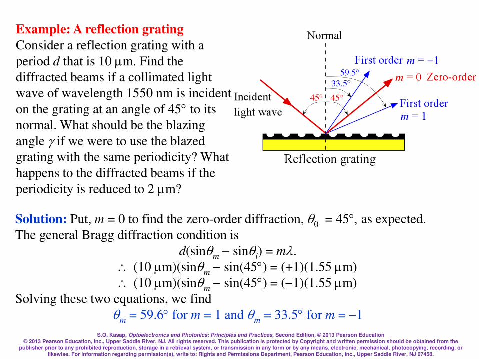
S.O. Kasap, Optoelectronics and Photonics: Principles and Practices, Second Edition, © 2013 Pearson Education © 2013 Pearson Education, Inc., Upper Saddle River, NJ. All rights reserved. This publication is protected by Copyright and written permission should be obtained from the
publisher prior to any prohibited reproduction, storage in a retrieval system, or transmission in any form or by any means, electronic, mechanical, photocopying, recording, or likewise. For information regarding permission(s), write to: Rights and Permissions Department, Pearson Education, Inc., Upper Saddle River, NJ 07458.
Example: A reflection grating
Consider a reflection grating with a
period d that is 10 m. Find the
diffracted beams if a collimated light
wave of wavelength 1550 nm is incident
on the grating at an angle of 45 to its
normal. What should be the blazing
angle if we were to use the blazed
grating with the same periodicity? What
happens to the diffracted beams if the
periodicity is reduced to 2 m?
Solution: Put, m = 0 to find the zero-order diffraction, q0 = 45, as expected.
The general Bragg diffraction condition is
d(sinqm sinqi) = m.
(10 m)(sinqm sin(45) = (+1)(1.55 m)
(10 m)(sinqm sin(45) = (1)(1.55 m)
Solving these two equations, we find
qm = 59.6 for m = 1 and qm = 33.5 for m = 1
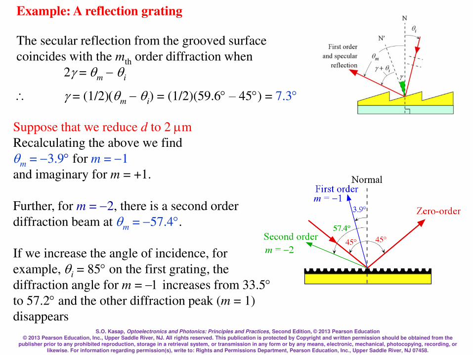
S.O. Kasap, Optoelectronics and Photonics: Principles and Practices, Second Edition, © 2013 Pearson Education © 2013 Pearson Education, Inc., Upper Saddle River, NJ. All rights reserved. This publication is protected by Copyright and written permission should be obtained from the
publisher prior to any prohibited reproduction, storage in a retrieval system, or transmission in any form or by any means, electronic, mechanical, photocopying, recording, or likewise. For information regarding permission(s), write to: Rights and Permissions Department, Pearson Education, Inc., Upper Saddle River, NJ 07458.
Example: A reflection grating
The secular reflection from the grooved surface
coincides with the mth order diffraction when
2 = qm qi
= (1/2)(qm qi) = (1/2)(59.6 – 45) = 7.3
Suppose that we reduce d to 2 m
Recalculating the above we find
qm = 3.9 for m = 1
and imaginary for m = +1.
Further, for m = 2, there is a second order
diffraction beam at qm = 57.4.
If we increase the angle of incidence, for
example, qi = 85 on the first grating, the
diffraction angle for m = 1 increases from 33.5 to 57.2 and the other diffraction peak (m = 1)
disappears

S.O. Kasap, Optoelectronics and Photonics: Principles and Practices, Second Edition, © 2013 Pearson Education © 2013 Pearson Education, Inc., Upper Saddle River, NJ. All rights reserved. This publication is protected by Copyright and written permission should be obtained from the
publisher prior to any prohibited reproduction, storage in a retrieval system, or transmission in any form or by any means, electronic, mechanical, photocopying, recording, or likewise. For information regarding permission(s), write to: Rights and Permissions Department, Pearson Education, Inc., Upper Saddle River, NJ 07458.
Experiments with Diffraction Gratings
Diffraction grating (2000 lines/inch)
Blue = 402 nm
Green = 532 nm
Red = 670 nm
Why do the diffraction spots become further separated
as you increase the wavelength?
Photo by SK

S.O. Kasap, Optoelectronics and Photonics: Principles and Practices, Second Edition, © 2013 Pearson Education © 2013 Pearson Education, Inc., Upper Saddle River, NJ. All rights reserved. This publication is protected by Copyright and written permission should be obtained from the
publisher prior to any prohibited reproduction, storage in a retrieval system, or transmission in any form or by any means, electronic, mechanical, photocopying, recording, or likewise. For information regarding permission(s), write to: Rights and Permissions Department, Pearson Education, Inc., Upper Saddle River, NJ 07458.
ANSWER
dsinq1 = m
dsinq2 = (m+1)d(sinq2sinq1) =
d
qqq = 12
sinqq
Angular separation of spots

S.O. Kasap, Optoelectronics and Photonics: Principles and Practices, Second Edition, © 2013 Pearson Education © 2013 Pearson Education, Inc., Upper Saddle River, NJ. All rights reserved. This publication is protected by Copyright and written permission should be obtained from the
publisher prior to any prohibited reproduction, storage in a retrieval system, or transmission in any form or by any means, electronic, mechanical, photocopying, recording, or likewise. For information regarding permission(s), write to: Rights and Permissions Department, Pearson Education, Inc., Upper Saddle River, NJ 07458.
We can separate wavelengths by using a
diffraction grating
Useful in Wavelength Division Multiplexing
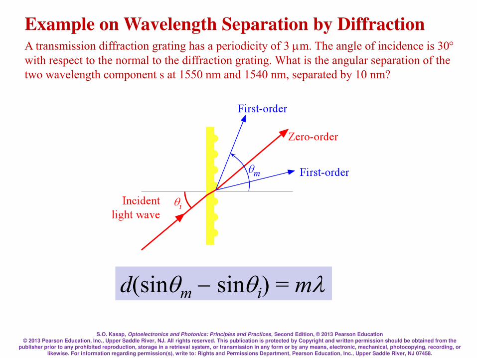
S.O. Kasap, Optoelectronics and Photonics: Principles and Practices, Second Edition, © 2013 Pearson Education © 2013 Pearson Education, Inc., Upper Saddle River, NJ. All rights reserved. This publication is protected by Copyright and written permission should be obtained from the
publisher prior to any prohibited reproduction, storage in a retrieval system, or transmission in any form or by any means, electronic, mechanical, photocopying, recording, or likewise. For information regarding permission(s), write to: Rights and Permissions Department, Pearson Education, Inc., Upper Saddle River, NJ 07458.
A transmission diffraction grating has a periodicity of 3 m. The angle of incidence is 30 with respect to the normal to the diffraction grating. What is the angular separation of the
two wavelength component s at 1550 nm and 1540 nm, separated by 10 nm?
Example on Wavelength Separation by Diffraction
d(sinqm sinqi) = m
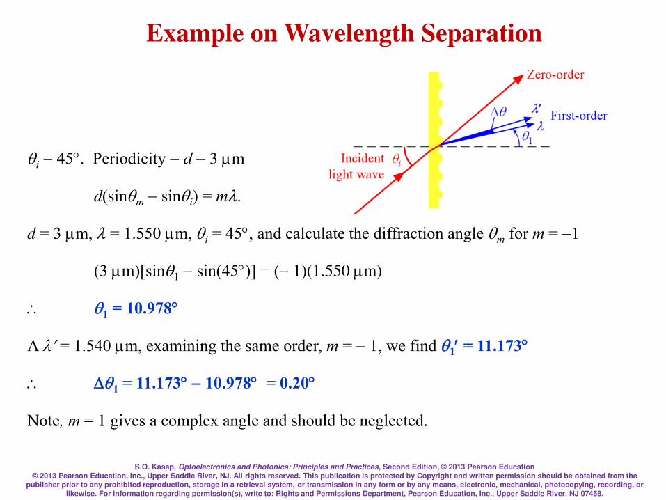
S.O. Kasap, Optoelectronics and Photonics: Principles and Practices, Second Edition, © 2013 Pearson Education © 2013 Pearson Education, Inc., Upper Saddle River, NJ. All rights reserved. This publication is protected by Copyright and written permission should be obtained from the
publisher prior to any prohibited reproduction, storage in a retrieval system, or transmission in any form or by any means, electronic, mechanical, photocopying, recording, or likewise. For information regarding permission(s), write to: Rights and Permissions Department, Pearson Education, Inc., Upper Saddle River, NJ 07458.
Example on Wavelength Separation
qi = 45. Periodicity = d = 3 m
d(sinqm sinqi) = m.
d = 3 m, = 1.550 m, qi = 45, and calculate the diffraction angle qm for m = 1
(3 m)[sinq1 sin(45)] = (1)(1.550 m)
q1 = 10.978
A = 1.540m, examining the same order, m = 1, we find q1 = 11.173
q1 = 11.17310.978 = 0.20
Note, m = 1 gives a complex angle and should be neglected.
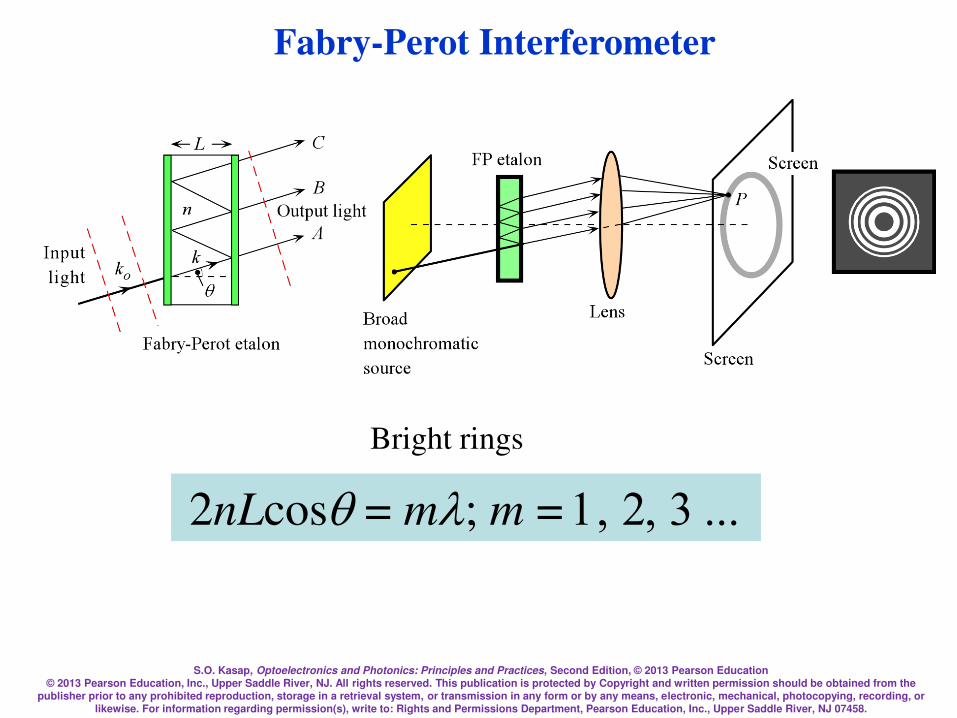
S.O. Kasap, Optoelectronics and Photonics: Principles and Practices, Second Edition, © 2013 Pearson Education © 2013 Pearson Education, Inc., Upper Saddle River, NJ. All rights reserved. This publication is protected by Copyright and written permission should be obtained from the
publisher prior to any prohibited reproduction, storage in a retrieval system, or transmission in any form or by any means, electronic, mechanical, photocopying, recording, or likewise. For information regarding permission(s), write to: Rights and Permissions Department, Pearson Education, Inc., Upper Saddle River, NJ 07458.
Fabry-Perot Interferometer
Bright rings
2nLcosq = m; m = 1,2,3...

S.O. Kasap, Optoelectronics and Photonics: Principles and Practices, Second Edition, © 2013 Pearson Education © 2013 Pearson Education, Inc., Upper Saddle River, NJ. All rights reserved. This publication is protected by Copyright and written permission should be obtained from the
publisher prior to any prohibited reproduction, storage in a retrieval system, or transmission in any form or by any means, electronic, mechanical, photocopying, recording, or likewise. For information regarding permission(s), write to: Rights and Permissions Department, Pearson Education, Inc., Upper Saddle River, NJ 07458.
Mach-Zehnder Interferometer
OBCkdkdOACk oo = )(
)(2
)( ndkd ==

S.O. Kasap, Optoelectronics and Photonics: Principles and Practices, Second Edition, © 2013 Pearson Education © 2013 Pearson Education, Inc., Upper Saddle River, NJ. All rights reserved. This publication is protected by Copyright and written permission should be obtained from the
publisher prior to any prohibited reproduction, storage in a retrieval system, or transmission in any form or by any means, electronic, mechanical, photocopying, recording, or likewise. For information regarding permission(s), write to: Rights and Permissions Department, Pearson Education, Inc., Upper Saddle River, NJ 07458.
Thin Films Optics
= (2)n2d
Assume normal incidence
Areflected/A0 = r1 + t1t1r2ej
t1t1r1r22ej2
t1t1r12r2
3ej3
Areflected = A1 + A2 + A3 + A4 +

S.O. Kasap, Optoelectronics and Photonics: Principles and Practices, Second Edition, © 2013 Pearson Education © 2013 Pearson Education, Inc., Upper Saddle River, NJ. All rights reserved. This publication is protected by Copyright and written permission should be obtained from the
publisher prior to any prohibited reproduction, storage in a retrieval system, or transmission in any form or by any means, electronic, mechanical, photocopying, recording, or likewise. For information regarding permission(s), write to: Rights and Permissions Department, Pearson Education, Inc., Upper Saddle River, NJ 07458.
Thin Films Optics
r =
r1 r2e j 2
1 r1r2e j 2
1 3
2
1 21
j
j
e
e
=t t
tr r
t1 = t12 =2n1
n1 n2
t 2 = t 21 =2n2
n1 n2
33 23
2 3
2nt t
n n= =
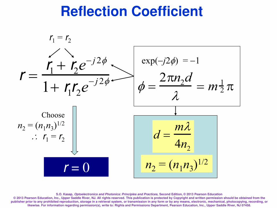
S.O. Kasap, Optoelectronics and Photonics: Principles and Practices, Second Edition, © 2013 Pearson Education © 2013 Pearson Education, Inc., Upper Saddle River, NJ. All rights reserved. This publication is protected by Copyright and written permission should be obtained from the
publisher prior to any prohibited reproduction, storage in a retrieval system, or transmission in any form or by any means, electronic, mechanical, photocopying, recording, or likewise. For information regarding permission(s), write to: Rights and Permissions Department, Pearson Education, Inc., Upper Saddle River, NJ 07458.
Reflection Coefficient
=2n2d
= m 1
2
r = 0
d =m4n2
exp(j2) = 1
r1 = r2
r =
r1 r2e j 2
1 r1r2e j 2
Choose
n2 = (n1n3)1/2
r1 = r2
n2 = (n1n3)1/2

S.O. Kasap, Optoelectronics and Photonics: Principles and Practices, Second Edition, © 2013 Pearson Education © 2013 Pearson Education, Inc., Upper Saddle River, NJ. All rights reserved. This publication is protected by Copyright and written permission should be obtained from the
publisher prior to any prohibited reproduction, storage in a retrieval system, or transmission in any form or by any means, electronic, mechanical, photocopying, recording, or likewise. For information regarding permission(s), write to: Rights and Permissions Department, Pearson Education, Inc., Upper Saddle River, NJ 07458.
Transmission Coefficient
1 3
2
1 21
j
j
e
e
=t t
tr r
=2n2d
= m 1
2
t = Maximum
d =m4n2
exp(j2) = 1

S.O. Kasap, Optoelectronics and Photonics: Principles and Practices, Second Edition, © 2013 Pearson Education © 2013 Pearson Education, Inc., Upper Saddle River, NJ. All rights reserved. This publication is protected by Copyright and written permission should be obtained from the
publisher prior to any prohibited reproduction, storage in a retrieval system, or transmission in any form or by any means, electronic, mechanical, photocopying, recording, or likewise. For information regarding permission(s), write to: Rights and Permissions Department, Pearson Education, Inc., Upper Saddle River, NJ 07458.
Minimum and Maximum Reflectance
2
31
2
2
31
2
2min
=nnn
nnnR
2
13
13max
=nn
nnRn1 < n2 < n3
n1 < n3 < n2 then Rmin and Rmax equations are interchanged
While Rmax appears to be independent from n2, the index n2 is
nonetheless still involved in determining maximum reflection
inasmuch as R reaches Rmax when = 2(2)n2d = (2m);
when =(even number)

S.O. Kasap, Optoelectronics and Photonics: Principles and Practices, Second Edition, © 2013 Pearson Education © 2013 Pearson Education, Inc., Upper Saddle River, NJ. All rights reserved. This publication is protected by Copyright and written permission should be obtained from the
publisher prior to any prohibited reproduction, storage in a retrieval system, or transmission in any form or by any means, electronic, mechanical, photocopying, recording, or likewise. For information regarding permission(s), write to: Rights and Permissions Department, Pearson Education, Inc., Upper Saddle River, NJ 07458.
Reflectance and Transmittance of a Thin Film Coating
(a) Reflectance R and transmittance T vs. = 2n2d/, for a thin film on a substrate
where n1 = 1 (air), n2 = 2.5 and n3 = 3.5, and n1 < n2 < n3. (b) R and T vs for a
thin film on a substrate where n1 = 1 (air), n2 = 3.5 and n3 = 2.5, and n2 > n3 > n1
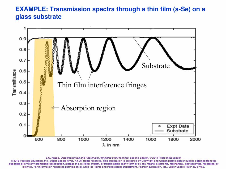
S.O. Kasap, Optoelectronics and Photonics: Principles and Practices, Second Edition, © 2013 Pearson Education © 2013 Pearson Education, Inc., Upper Saddle River, NJ. All rights reserved. This publication is protected by Copyright and written permission should be obtained from the
publisher prior to any prohibited reproduction, storage in a retrieval system, or transmission in any form or by any means, electronic, mechanical, photocopying, recording, or likewise. For information regarding permission(s), write to: Rights and Permissions Department, Pearson Education, Inc., Upper Saddle River, NJ 07458.
EXAMPLE: Transmission spectra through a thin film (a-Se) on a glass substrate
Absorption region
Thin film interference fringes
Substrate

S.O. Kasap, Optoelectronics and Photonics: Principles and Practices, Second Edition, © 2013 Pearson Education © 2013 Pearson Education, Inc., Upper Saddle River, NJ. All rights reserved. This publication is protected by Copyright and written permission should be obtained from the
publisher prior to any prohibited reproduction, storage in a retrieval system, or transmission in any form or by any means, electronic, mechanical, photocopying, recording, or likewise. For information regarding permission(s), write to: Rights and Permissions Department, Pearson Education, Inc., Upper Saddle River, NJ 07458.
Example: Thin Film Optics
Consider a semiconductor device with n3 = 3.5 that
has been coated with a transparent optical film (a
dielectric film) with n2 = 2.5, n1 = 1 (air). If the film
thickness is 160 nm, find the minimum and
maximum reflectances and transmittances and their
corresponding wavelengths in the visible range.
(Assume normal incidence.)
Solution: We have n1 < n2 < n3. Rmin occurs at = or odd multiple of , and
maximum reflectance Rmax at = 2 or an integer multiple of 2 .
%0.8or080.0)5.3)(1(5.2
)5.3)(1(5.22
2
22
31
2
2
31
2
2min =
=
=nnn
nnnR
%31or31.015.3
15.322
13
13max =
=
=nn
nnR
Tmax = 1 – Rmin = 0.92 or 92%
Tmin = 1 – Rmax = 0.69 or 69%
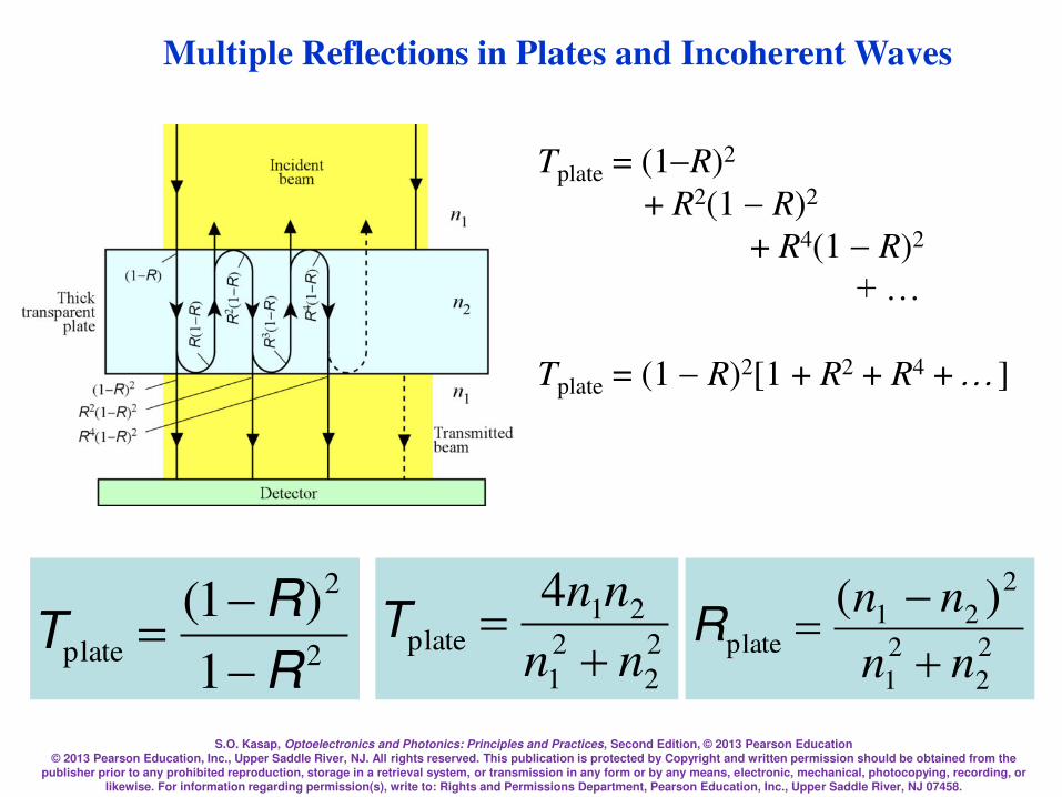
S.O. Kasap, Optoelectronics and Photonics: Principles and Practices, Second Edition, © 2013 Pearson Education © 2013 Pearson Education, Inc., Upper Saddle River, NJ. All rights reserved. This publication is protected by Copyright and written permission should be obtained from the
publisher prior to any prohibited reproduction, storage in a retrieval system, or transmission in any form or by any means, electronic, mechanical, photocopying, recording, or likewise. For information regarding permission(s), write to: Rights and Permissions Department, Pearson Education, Inc., Upper Saddle River, NJ 07458.
Multiple Reflections in Plates and Incoherent Waves
Tplate = (1R)2
+ R2(1R)2
+ R4(1R)2
+ …
Tplate = (1R)2[1 + R2 + R4 + ]
2
2
plate1
)1(
R
RT
= 2
2
2
1
21plate
4
nn
nn
=T
2
2
2
1
2
21plate
)(
nn
nn
=R
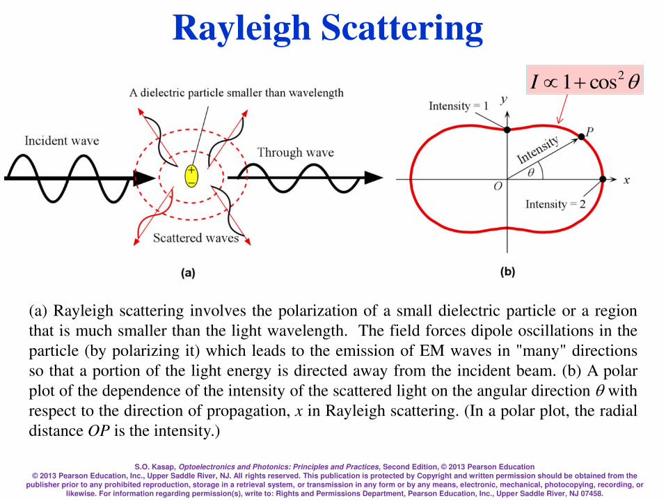
S.O. Kasap, Optoelectronics and Photonics: Principles and Practices, Second Edition, © 2013 Pearson Education © 2013 Pearson Education, Inc., Upper Saddle River, NJ. All rights reserved. This publication is protected by Copyright and written permission should be obtained from the
publisher prior to any prohibited reproduction, storage in a retrieval system, or transmission in any form or by any means, electronic, mechanical, photocopying, recording, or likewise. For information regarding permission(s), write to: Rights and Permissions Department, Pearson Education, Inc., Upper Saddle River, NJ 07458.
Rayleigh Scattering
(a) Rayleigh scattering involves the polarization of a small dielectric particle or a region
that is much smaller than the light wavelength. The field forces dipole oscillations in the
particle (by polarizing it) which leads to the emission of EM waves in "many" directions
so that a portion of the light energy is directed away from the incident beam. (b) A polar
plot of the dependence of the intensity of the scattered light on the angular direction q with
respect to the direction of propagation, x in Rayleigh scattering. (In a polar plot, the radial
distance OP is the intensity.)
q2cos1I
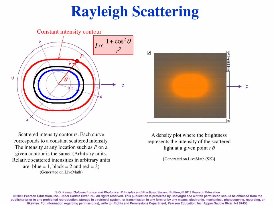
S.O. Kasap, Optoelectronics and Photonics: Principles and Practices, Second Edition, © 2013 Pearson Education © 2013 Pearson Education, Inc., Upper Saddle River, NJ. All rights reserved. This publication is protected by Copyright and written permission should be obtained from the
publisher prior to any prohibited reproduction, storage in a retrieval system, or transmission in any form or by any means, electronic, mechanical, photocopying, recording, or likewise. For information regarding permission(s), write to: Rights and Permissions Department, Pearson Education, Inc., Upper Saddle River, NJ 07458.
Rayleigh Scattering
A density plot where the brightness
represents the intensity of the scattered
light at a given point r,q
[Generated on LiveMath (SK)]
2
4
6
q
0 .5 1 1 .5r
Scattered intensity contours. Each curve
corresponds to a constant scattered intensity.
The intensity at any location such as P on a
given contour is the same. (Arbitrary units.
Relative scattered intensities in arbitrary units
are: blue = 1, black = 2 and red = 3) (Generated on LiveMath)
Constant intensity contour
r
q
P
2
2cos1
rI
q
-2
0
2
y
-2 0 2xzz
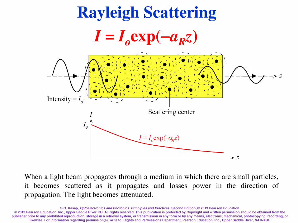
S.O. Kasap, Optoelectronics and Photonics: Principles and Practices, Second Edition, © 2013 Pearson Education © 2013 Pearson Education, Inc., Upper Saddle River, NJ. All rights reserved. This publication is protected by Copyright and written permission should be obtained from the
publisher prior to any prohibited reproduction, storage in a retrieval system, or transmission in any form or by any means, electronic, mechanical, photocopying, recording, or likewise. For information regarding permission(s), write to: Rights and Permissions Department, Pearson Education, Inc., Upper Saddle River, NJ 07458.
Rayleigh Scattering
I = Ioexp(aRz)
When a light beam propagates through a medium in which there are small particles,
it becomes scattered as it propagates and losses power in the direction of
propagation. The light becomes attenuated.

S.O. Kasap, Optoelectronics and Photonics: Principles and Practices, Second Edition, © 2013 Pearson Education © 2013 Pearson Education, Inc., Upper Saddle River, NJ. All rights reserved. This publication is protected by Copyright and written permission should be obtained from the
publisher prior to any prohibited reproduction, storage in a retrieval system, or transmission in any form or by any means, electronic, mechanical, photocopying, recording, or likewise. For information regarding permission(s), write to: Rights and Permissions Department, Pearson Education, Inc., Upper Saddle River, NJ 07458.
Rayleigh Scattering
I = Ioexp(aRz)
2
22
22
4
6 1
o
o
Rnn
nnaN
Rayleigh attenuation coefficient
Lord Rayleigh (John William Strutt) was an English physicist (1877–1919) and a
Nobel Laureate (1904) who made a number of contributions to wave physics of
sound and optics. He formulated the theory of scattering of light by small particles
and the dependence of scattering on 1/4 circa 1871. Then, in a paper in 1899 he
provided a clear explanation on why the sky is blue. Ludvig Lorentz, around the
same time, and independently, also formulated the scattering of waves from a small
dielectric particle, though it was published in Danish (1890).40 (© Mary Evans
Picture Library/Alamy.)

S.O. Kasap, Optoelectronics and Photonics: Principles and Practices, Second Edition, © 2013 Pearson Education © 2013 Pearson Education, Inc., Upper Saddle River, NJ. All rights reserved. This publication is protected by Copyright and written permission should be obtained from the
publisher prior to any prohibited reproduction, storage in a retrieval system, or transmission in any form or by any means, electronic, mechanical, photocopying, recording, or likewise. For information regarding permission(s), write to: Rights and Permissions Department, Pearson Education, Inc., Upper Saddle River, NJ 07458.
Photonic Crystals
Photonic crystals in (a) 1D, (b) 2D and (c) 3D, D being the dimension. Grey
and white regions have different refractive indices and may not necessarily be
the same size. L is the periodicity. The 1D photonic crystal in (a) is the well-
known Bragg reflector, a dielectric stack.
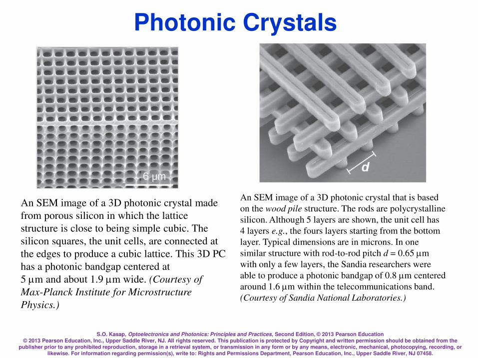
S.O. Kasap, Optoelectronics and Photonics: Principles and Practices, Second Edition, © 2013 Pearson Education © 2013 Pearson Education, Inc., Upper Saddle River, NJ. All rights reserved. This publication is protected by Copyright and written permission should be obtained from the
publisher prior to any prohibited reproduction, storage in a retrieval system, or transmission in any form or by any means, electronic, mechanical, photocopying, recording, or likewise. For information regarding permission(s), write to: Rights and Permissions Department, Pearson Education, Inc., Upper Saddle River, NJ 07458.
An SEM image of a 3D photonic crystal that is based
on the wood pile structure. The rods are polycrystalline
silicon. Although 5 layers are shown, the unit cell has
4 layers e.g., the fours layers starting from the bottom
layer. Typical dimensions are in microns. In one
similar structure with rod-to-rod pitch d = 0.65 m
with only a few layers, the Sandia researchers were
able to produce a photonic bandgap of 0.8 m centered
around 1.6 m within the telecommunications band.
(Courtesy of Sandia National Laboratories.)
Photonic Crystals
An SEM image of a 3D photonic crystal made
from porous silicon in which the lattice
structure is close to being simple cubic. The
silicon squares, the unit cells, are connected at
the edges to produce a cubic lattice. This 3D PC
has a photonic bandgap centered at
5 m and about 1.9 m wide. (Courtesy of
Max-Planck Institute for Microstructure
Physics.)
S.O. Kasap, Optoelectronics and Photonics: Principles and Practices, Second Edition, © 2013 Pearson Education © 2013 Pearson Education, Inc., Upper Saddle River, NJ. All rights reserved. This publication is protected by Copyright and written permission should be obtained from the
publisher prior to any prohibited reproduction, storage in a retrieval system, or transmission in any form or by any means, electronic, mechanical, photocopying, recording, or likewise. For information regarding permission(s), write to: Rights and Permissions Department, Pearson Education, Inc., Upper Saddle River, NJ 07458.
Photonic Crystals
Eli Yablonovitch (left) at the University of California
at Berkeley, and Sajeev John (below) at the
University of Toronto, carried out the initial
pioneering work on photonic crystals. Eli
Yablonovitch has suggested that the name "photonic
crystal" should apply to 2D and 3D periodic
structures with a large dielectric (refractive index)
difference. (E. Yablonovitch, "Photonic crystals:
what's in a name?", Opt. Photon. News, 18, 12,
2007.) Their original papers were published in the
same volume of Physical Review Letters in 1987.
According to Eli Yablonovitch, "Photonic Crystals are
semiconductors for light.“ (Courtesy of Eli Yablonovitch)
Sajeev John (left), at the University of Toronto,
along with Eli Yablonovitch (above) carried out
the initial pioneering work in the development of
the field of photonics crystals. Sajeev John was
able to show that it is possible to trap light in a
similar way the electron is captured, that is
localized, by a trap in a semiconductor. Defects
in photonic crystals can confine or localize
electromagnetic waves; such effects have
important applications in quantum computing
and integrated photonics. (Courtesy of Sajeev
John)
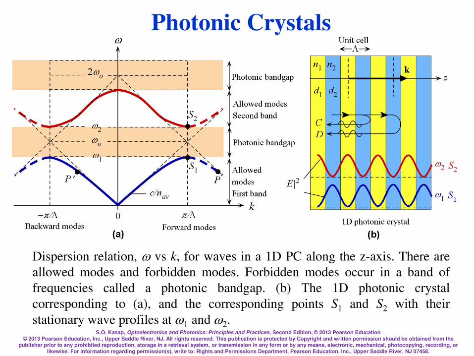
S.O. Kasap, Optoelectronics and Photonics: Principles and Practices, Second Edition, © 2013 Pearson Education © 2013 Pearson Education, Inc., Upper Saddle River, NJ. All rights reserved. This publication is protected by Copyright and written permission should be obtained from the
publisher prior to any prohibited reproduction, storage in a retrieval system, or transmission in any form or by any means, electronic, mechanical, photocopying, recording, or likewise. For information regarding permission(s), write to: Rights and Permissions Department, Pearson Education, Inc., Upper Saddle River, NJ 07458.
Dispersion relation, vs k, for waves in a 1D PC along the z-axis. There are
allowed modes and forbidden modes. Forbidden modes occur in a band of
frequencies called a photonic bandgap. (b) The 1D photonic crystal
corresponding to (a), and the corresponding points S1 and S2 with their
stationary wave profiles at 1 and 2.
Photonic Crystals
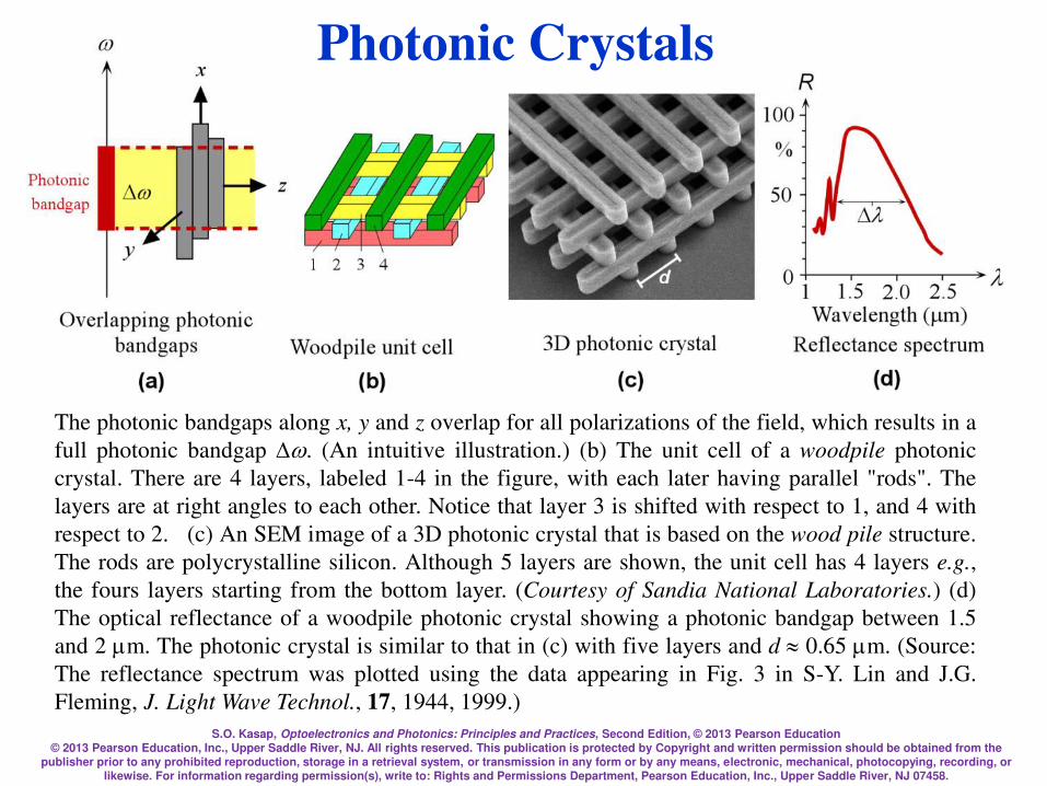
S.O. Kasap, Optoelectronics and Photonics: Principles and Practices, Second Edition, © 2013 Pearson Education © 2013 Pearson Education, Inc., Upper Saddle River, NJ. All rights reserved. This publication is protected by Copyright and written permission should be obtained from the
publisher prior to any prohibited reproduction, storage in a retrieval system, or transmission in any form or by any means, electronic, mechanical, photocopying, recording, or likewise. For information regarding permission(s), write to: Rights and Permissions Department, Pearson Education, Inc., Upper Saddle River, NJ 07458.
The photonic bandgaps along x, y and z overlap for all polarizations of the field, which results in a
full photonic bandgap . (An intuitive illustration.) (b) The unit cell of a woodpile photonic
crystal. There are 4 layers, labeled 1-4 in the figure, with each later having parallel "rods". The
layers are at right angles to each other. Notice that layer 3 is shifted with respect to 1, and 4 with
respect to 2. (c) An SEM image of a 3D photonic crystal that is based on the wood pile structure.
The rods are polycrystalline silicon. Although 5 layers are shown, the unit cell has 4 layers e.g.,
the fours layers starting from the bottom layer. (Courtesy of Sandia National Laboratories.) (d)
The optical reflectance of a woodpile photonic crystal showing a photonic bandgap between 1.5
and 2 m. The photonic crystal is similar to that in (c) with five layers and d 0.65 m. (Source:
The reflectance spectrum was plotted using the data appearing in Fig. 3 in S-Y. Lin and J.G.
Fleming, J. Light Wave Technol., 17, 1944, 1999.)
Photonic Crystals

S.O. Kasap, Optoelectronics and Photonics: Principles and Practices, Second Edition, © 2013 Pearson Education © 2013 Pearson Education, Inc., Upper Saddle River, NJ. All rights reserved. This publication is protected by Copyright and written permission should be obtained from the
publisher prior to any prohibited reproduction, storage in a retrieval system, or transmission in any form or by any means, electronic, mechanical, photocopying, recording, or likewise. For information regarding permission(s), write to: Rights and Permissions Department, Pearson Education, Inc., Upper Saddle River, NJ 07458.
Photonic Crystals for Light Manipulation
Schematic illustration of point and line defects in a photonic crystal. A point defect acts
as an optical cavity, trapping the radiation. Line defects allow the light to propagate
along the defect line. The light is prevented from dispersing into the bulk of the crystal
since the structure has a full photonic bandgap. The frequency of the propagating light is
in the bandgap, that is in the stop-band.
S.O. Kasap, Optoelectronics and Photonics: Principles and Practices, Second Edition, © 2013 Pearson Education © 2013 Pearson Education, Inc., Upper Saddle River, NJ. All rights reserved. This publication is protected by Copyright and written permission should be obtained from the
publisher prior to any prohibited reproduction, storage in a retrieval system, or transmission in any form or by any means, electronic, mechanical, photocopying, recording, or likewise. For information regarding permission(s), write to: Rights and Permissions Department, Pearson Education, Inc., Upper Saddle River, NJ 07458.
Slides on Questions and
Problems
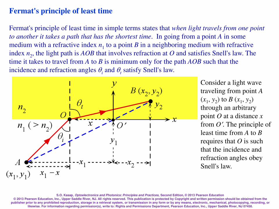
S.O. Kasap, Optoelectronics and Photonics: Principles and Practices, Second Edition, © 2013 Pearson Education © 2013 Pearson Education, Inc., Upper Saddle River, NJ. All rights reserved. This publication is protected by Copyright and written permission should be obtained from the
publisher prior to any prohibited reproduction, storage in a retrieval system, or transmission in any form or by any means, electronic, mechanical, photocopying, recording, or likewise. For information regarding permission(s), write to: Rights and Permissions Department, Pearson Education, Inc., Upper Saddle River, NJ 07458.
Fermat's principle of least time
Fermat's principle of least time in simple terms states that when light travels from one point
to another it takes a path that has the shortest time. In going from a point A in some
medium with a refractive index n1 to a point B in a neighboring medium with refractive
index n2, the light path is AOB that involves refraction at O and satisfies Snell's law. The
time it takes to travel from A to B is minimum only for the path AOB such that the
incidence and refraction angles qi and qt satisfy Snell's law.
Consider a light wave
traveling from point A
(x1, y2) to B (x1, y2)
through an arbitrary
point O at a distance x
from O. The principle of
least time from A to B
requires that O is such
that the incidence and
refraction angles obey
Snell's law.
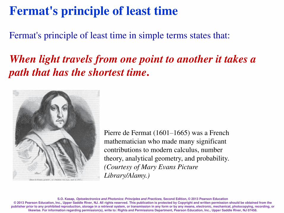
S.O. Kasap, Optoelectronics and Photonics: Principles and Practices, Second Edition, © 2013 Pearson Education © 2013 Pearson Education, Inc., Upper Saddle River, NJ. All rights reserved. This publication is protected by Copyright and written permission should be obtained from the
publisher prior to any prohibited reproduction, storage in a retrieval system, or transmission in any form or by any means, electronic, mechanical, photocopying, recording, or likewise. For information regarding permission(s), write to: Rights and Permissions Department, Pearson Education, Inc., Upper Saddle River, NJ 07458.
Fermat's principle of least time
Fermat's principle of least time in simple terms states that:
When light travels from one point to another it takes a
path that has the shortest time.
Pierre de Fermat (1601–1665) was a French
mathematician who made many significant
contributions to modern calculus, number
theory, analytical geometry, and probability.
(Courtesy of Mary Evans Picture
Library/Alamy.)

S.O. Kasap, Optoelectronics and Photonics: Principles and Practices, Second Edition, © 2013 Pearson Education © 2013 Pearson Education, Inc., Upper Saddle River, NJ. All rights reserved. This publication is protected by Copyright and written permission should be obtained from the
publisher prior to any prohibited reproduction, storage in a retrieval system, or transmission in any form or by any means, electronic, mechanical, photocopying, recording, or likewise. For information regarding permission(s), write to: Rights and Permissions Department, Pearson Education, Inc., Upper Saddle River, NJ 07458.
Fermat's principle of least time
Let's draw a straight line from A to B cutting the x-axes at O. The line AOB will be our
reference line and we will place the origin of x and y coordinates at O. Without invoking
Snell's law, we will vary point O along the x-axis (hence OO is a variable labeled x), until
the time it takes to travel AOB is minimum, and thereby derive Snell's law. The time t it
takes for light to travel from A to B through O is
2
2/12
2
2
2
1
2/12
1
2
1
21
/
])[(
/
])[(
//
nc
yxx
nc
yxx
nc
OB
nc
AOt
=
=
2/12
1
2
1
1
])[(sin
yxx
xxi
=q
2
2 2 1/2
2 2
( )sin
[( ) ]t
x x
x x yq =

S.O. Kasap, Optoelectronics and Photonics: Principles and Practices, Second Edition, © 2013 Pearson Education © 2013 Pearson Education, Inc., Upper Saddle River, NJ. All rights reserved. This publication is protected by Copyright and written permission should be obtained from the
publisher prior to any prohibited reproduction, storage in a retrieval system, or transmission in any form or by any means, electronic, mechanical, photocopying, recording, or likewise. For information regarding permission(s), write to: Rights and Permissions Department, Pearson Education, Inc., Upper Saddle River, NJ 07458.
2
2/12
2
2
2
1
2/12
1
2
1
21
/
])[(
/
])[(
//
nc
yxx
nc
yxx
nc
OB
nc
AOt
=
=
2 2 1/2 2 2 1/2
1 1 1 2 2 2
1 2
1/ 2 2( )[( ) ] 1/ 2 2( )[( ) ]
/ /
x x x x y x x x x ydt
dx c n c n
=
The time should be minimum so 0dt
dx=
2 2 1/2 2 2 1/2
1 1 1 2 2 2
1 2
( )[( ) ] ( )[( ) ]0
/ /
x x x x y x x x x y
c n c n
=
1 2
2 2 1/2 2 2 1/2
1 1 1 2 1 1
( ) ( )
/ [( ) ] / [( ) ]
x x x x
c n x x y c n x x y
=
1 2sin sini t
n nq q=
Snell’s Law

S.O. Kasap, Optoelectronics and Photonics: Principles and Practices, Second Edition, © 2013 Pearson Education © 2013 Pearson Education, Inc., Upper Saddle River, NJ. All rights reserved. This publication is protected by Copyright and written permission should be obtained from the
publisher prior to any prohibited reproduction, storage in a retrieval system, or transmission in any form or by any means, electronic, mechanical, photocopying, recording, or likewise. For information regarding permission(s), write to: Rights and Permissions Department, Pearson Education, Inc., Upper Saddle River, NJ 07458.
Updates and Corrected Slides
Class Demonstrations
Class Problems
Check author’s website http://optoelectronics.usask.ca
Email errors and corrections to [email protected]
Related Documents


