1 Telecommunication Engineering group University of Twente, Enschede, The Netherlands International Workshop on Phased Array Antenna Systems for Radio Astronomy May 3-5, 2010 Design Optimization of Phased Arrays and RF Electronics Photonic Integrated Beamformer for Broadband Radio Astronomy A. Leinse, M. Hoekman, R. G. Heideman LioniX BV, Enschede, The Netherlands M. Burla , D. A. I. Marpaung, M. R. H. Khan, C. G. H. Roeloffzen P. Maat, K. Dijkstra ASTRON, Dwingeloo, The Netherlands

Welcome message from author
This document is posted to help you gain knowledge. Please leave a comment to let me know what you think about it! Share it to your friends and learn new things together.
Transcript
1
Telecommunication Engineering group University of Twente, Enschede, The Netherlands
International Workshop on Phased Array Antenna Systems
for Radio AstronomyMay 3-5, 2010
Design Optimization of Phased Arrays and RF Electronics
Photonic Integrated Beamformer for Broadband Radio Astronomy
A. Leinse, M. Hoekman, R. G. Heideman LioniX BV, Enschede, The Netherlands
M. Burla, D. A. I. Marpaung, M. R. H. Khan, C. G. H. Roeloffzen
P. Maat, K. Dijkstra ASTRON, Dwingeloo, The Netherlands

2
Introduction
Photonic integrated beamformers- fields of application- RF-to-RF characterization- demonstration of broadband beamsteering
Integration
New architectures
Conclusions
Outline

3Telecommunication Engineering Group
• 6 scientific staff• 4 postdoctoral researchers• 12 PhD students• 6 MSc and BSc students
Three main research areas:
Short range radioElectromagnetic
compatibilityMicrowave Photonics

4Microwave Photonics Research
Signal distribution
Signal processing
Signal generation
• 1 scientific staff• 1 postdoctoral researcher• 2 PhD students• 2 BSc students
What we do:
Microwave photonics techniques High performance
Analog photonic links
Optical beamforming
Optical heterodyningfor LO generation

5
Possible applications: DVB-S, radio astronomy, …
Radio astronomyAirborne
DVB-S reception
Requirements: Broadband High-resolution, squint-free architecture Continuously tunable beam direction
Applications for optical beamforming

6
RF-to-RF characterization of a phased array antenna using an integrated OBFN
From
“RF-to-RF Characterization of a Phased Array Receive Antenna Steering System Using a Novel Ring Resonator-Based Integrated Photonic Beamformer”, L. Zhuang, M. Burla, C. G. H. Roeloffzen, A.
Meijerink, D. A. I. Marpaung, M. R. H. Khan, W. van Etten, A. Leinse, M. Hoekman, R. G. Heideman
Presented at the 2009 International Topical Meeting on MICROWAVE PHOTONICS, Valencia, Spain, 14-16 Oct. 2009. (Microwave Photonic Techniques for Antennas)

7
Beam forming network: Delay on
Phased array antenna: principle of operation
• Broadband phased antenna arrays require true time delays• Not easy to be realized over a broad band• Photonic technology can help…
Requirements
RF-to-RF characterization

8
0,0
-7,0
-6,0
-5,0
-4,0
-3,0
-2,0
-1,0
10230 100 200 300 400 500 600 700 800 900
Phase Output (lin scale)
ORR
Ideal delay line
L
• Optical delay generation: implemented using optical resonators
• Comparison of an Optical Ring Resonator (ORR) with an ideal delay line:
0,0
-7,0
-6,0
-5,0
-4,0
-3,0
-2,0
-1,0
10230 100 200 300 400 500 600 700 800 900
Phase Output (lin scale)
FSR
RF-to-RF characterization
f

9
Optical delay generation
T41
− 0T41
T21
T21
−
T8
T4
T2
T6
T10
0→ f
Group delay
TFSR 1
=
Optical ring resonator:
T : Round trip time
κ : Power coupling coefficient
φ : Additional phase
φ
κ
T π2−
0
π2.1−
π6.1−
π8.0−
π4.0−
Phase
Trade-off: delay vs bandwidth
RF-to-RF characterization

10
Optical delay generation
Enhanced bandwidth Trade-off: delay vs. bandwidth vs. delay ripple vs. no. rings
ripple
bandwidth
T41
− 0T41
T21
T21
−
→ f
T8
T4
T2
T6
0
→G
roup
del
ay
T10
T41
− 0T41
T21
T21
−
→ f
Cascaded ring resonators:
DesignRequired delay
Required BW
Least number of rings
Max ripple
Design procedure:
RF-to-RF characterization

11
Optical beam forming network (OBFN): binary tree architecture Reduction in the number of rings
RF-to-RF characterization
Integrated OBFN
4.95 cm
12
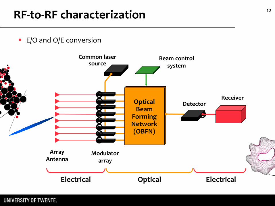
E/O and O/E conversion
OpticalBeam
Forming Network(OBFN)
Modulator array
Common laser source
Beam control system
Array Antenna
Receiver
Electrical Optical Electrical
Detector
RF-to-RF characterization

13
chip
Hybrid measurement setup
MZM
OBFNOSBF RF output
MZM
RF inputs
Common laser source
MZM
1 2 N Optical sideband filter to obtain SSB-SC
MZM in push-pull
mode to generate
DSB-SC
Carrier re-insertion and balanced detection
Optical SSB–SC modulation with balanced detection
RF-to-RF characterization
14
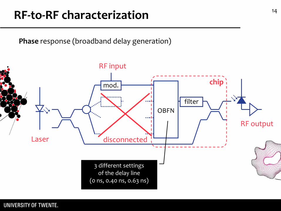
Phase response (broadband delay generation)
mod.
OBFNfilter
RF input
RF output
disconnectedLaser
3 different settingsof the delay line
(0 ns, 0.40 ns, 0.63 ns)
chip
RF-to-RF characterization

15
Phase response (broadband delay generation) Results [1]
RF phase shift vs frequency
3 delay settings:0 ns, 0.4 ns, 0.63 ns
Linear phase characteristic with frequency
TTD operation demonstrated
Ripple due to the Fabry-Perot reflections in the fiber connectors
ideal casemeasurement
[1] “RF-to-RF Characterization of a Phased Array Receive Antenna Steering System Using a Novel Ring Resonator-Based Integrated Photonic Beamformer”, L. Zhuang, M. Burla, C. G. H. Roeloffzen, A. Meijerink, D. A. I. Marpaung, M. R. H. Khan, W. van Etten, A. Leinse, M. Hoekman, R. G. Heideman, MWP 2009, Valencia, Spain, 14-16 Oct. 2009.
RF-to-RF characterization

16
OBFNfilter
RF output
RF input
4×1 splitter
mod.
mod.
mod.
mod.
delays tuned to compensate for different cable lengths
RF inputs terminated on matched loads: first in couples,
then individually
Matched loads
Power response (coherent combining)
RF-to-RF characterization

17
RF power output vs frequency
6 dB increase of the RF power level each time the number of combined signals is doubled
Coherent combining demonstrated
Power response (coherent combining) Results
~ 6 dB
~ 6 dB
RF-to-RF characterization

18
OBFN measurement: “SKY” demonstrator
Within SKADS (Square Kilometer Array Design Study)

19SKY demonstrator: an RF Photonic test bench
• Work carried on in ASTRON: modification of the EMBRACE phased array by using a photonic beamformer
• Operating band: 500-1500 MHz
• Use of a subarray of the original EMBRACE tile
Input 12
Input 11
Input 09
Input 10
4x1 array antenna

20
LNAs
Laser
OBFN chip
Detector
Modulators
4×1 subarray of Vivaldi antennas
near-field scanning
probe
OBFN controller
• Setup Sweeping laser
OSA
20 dBopticalsplitter
monitor opticaloutput
Modulator bias
SKY demonstrator
EMBRACE front-end
VNA

21
• Near-field antenna measurement
• Far-field are calculated using FFT on the basis of a near-field measurement
• IDEA: reduce the beamwidth θ by creating grating lobes
• Started by measuring an array of 2 AEs
• Because of the low frequency of the array compared to the room dimensions, difficult to measure large scan angles
Preliminary demonstrator

22
• Simulated patterns
-60 -40 -20 0 20 40 60-50
-45
-40
-35
-30
-25
-20
-15
-10
-5
0
Elevation [deg]
dire
ctiv
ity [d
Bi]
2×1, d = 3λ/215.9 deg
2×1, d = λ/255.6 deg
Preliminary demonstrator

23
~ Broadside
Preliminary demonstrator

24
- 14 deg
Preliminary demonstrator

25
• Antenna patterns: simulated vs measured
The radiation patterns measured for a 2 AEs array show a squint-freebeamsteering with at least 450 MHz instantaneous BW
(limited by the antenna test range only)
Preliminary demonstrator

26Towards optical integration
• Current work: extension to more antenna elements
• Difficulties: optical phase de-synchronization issues due to the presence of several meters of fiber between the splitting and the combining points generate output power fluctuations
• Need for integration to fully exploit the advantages given by the optical beamformer
• Current ongoing national and European projects (MEMPHIS, SANDRA) aim to a fully integrated system

27
brass heat sink
Silicon common base
OBFN controller
Temperature controller
Laser
shaped PCBModulator
drivers
Optical interconnection:
•Butt coupling: splitter – modulators –OBFN – detector
•Fiber: laser - splitter
IF front-end outputs
Integrated1×16 splitter
Symmetric Optical Beamformer
(UT-TE, LioniX)
Modulatorarray
PM fiber
Modulator drivers
Mechanical interconnection:
•Silicon common base
Optical detector
IF front-end outputs
Electrical interconnection:
•Wire bonding + PCB
• Application: phased array antenna for airborne Ku-band TV-SAT receiver
OBFN integration

28
New OBFN designs

29
3. Multi-beam OBFNfor multiple simultaneous beams- studies and simulations addressing several possible architectures
• New OBFN designs
1. Symmetric OBFNfor built-in symmetric beamsteering
2. Multi-wavelength OBFNemploying ORR periodicity for reduced dimensions

30
1. Symmetric OBFN (demonstrator 2): built-in symmetric beamsteering
Broadside (requires compensation)
ORRs set to minimum delay
Maximum angle
θmax
θmin
Asymmetric OBFN
θscan
New OBFN designs

31
1. Symmetric OBFN (demonstrator 2): built-in symmetric beamsteering
θscan/2
θscan/2
Symmetric OBFN
New OBFN designs
32
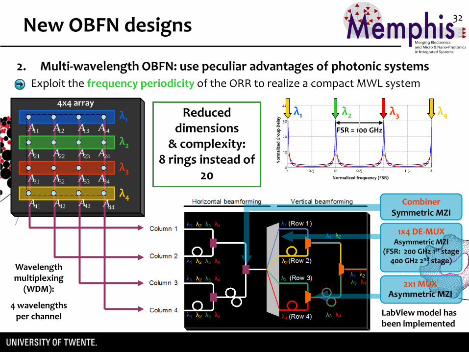
4x4 array
Wavelength multiplexing
(WDM):
4 wavelengths per channel
λ1
λ2
λ3
λ4
11A 12A 13A 14A
21A 22A 23A 24A
31A 32A 33A 34A
41A 42A 43A 44A
Exploit the frequency periodicity of the ORR to realize a compact MWL system
FSR = 100 GHz
LabView model hasbeen implemented
2x1 MUXAsymmetric MZI
1x4 DE-MUXAsymmetric MZI
(FSR: 200 GHz 1st stage 400 GHz 2nd stage)
CombinerSymmetric MZI
λ1 λ2 λ3 λ4Reduced dimensions
& complexity:8 rings instead of
20
2. Multi-wavelength OBFN: use peculiar advantages of photonic systems
New OBFN designs

33
OpticalBeam
Forming Network(OBFN)
Modulator array
laser source Beam control system
Array Antenna
ReceiverNEW
multiple beam OBFN
Detector
Beam 1
Beam 2
Beam 3
Beam 4
3. Multi-beam OBFN: multiple simultaneous & independent beams
New OBFN designs
possible FPA application

34
Waveguide technology optimized for low loss propagation: new geometry defined
“new”
First test samples finished. Results look promising (Expected atten. <0.2 dB/cm, bend. radius ≈ 100 um)
“old”
Waveguide technology

35
Realization of Basic Building Blocks (BBBs) on test mask for characterization (from FP7 SANDRA project)
Fabrication and characterization of the BBBs will be the input for the
new OBFN geometry
Waveguide technology

36
Conclusions

37
RF-to-RF measurements demonstrated:
continuously tunable delay generation - phase response
coherent combining capability - power response
Optical Beamformers based on Optical Ring Resonators
Conclusions
“SKY” OBFN demonstrator:
Radiation patterns measured for a 2 AEs array show a squint-freebeamsteering with at least 450 MHz instantaneous BW
Currently being extended to more AEs
Ongoing research for new OBFN architectures for:
symmetric scanning, reduced size, multiple beams (FPAs)
Currently completing a flexible control system for beam shape control

38
Thank you
International Workshop on Phased Array Antenna Systems
for Radio AstronomyMay 3-5, 2010
Design Optimization of Phased Arrays and RF Electronics
Related Documents