博士論文 Photocatalytic and Photoelectrochemical Water Splitting on Particulate SrTiO 3 (チタン酸ストロンチウム微粒子上での光触媒的及び光電気化学的水分解反応) Yeilin HAM (咸 藝麟) The Department of Chemical System Engineering, School of Engineering, The University of Tokyo 2015 Doctoral Thesis

Welcome message from author
This document is posted to help you gain knowledge. Please leave a comment to let me know what you think about it! Share it to your friends and learn new things together.
Transcript
博士論文
Photocatalytic and Photoelectrochemical Water
Splitting on Particulate SrTiO3
(チタン酸ストロンチウム微粒子上での光触媒的及び光電気化学的水分解反応)
Yeilin HAM (咸 藝麟)
The Department of Chemical System Engineering, School of Engineering,
The University of Tokyo
2015 Doctoral Thesis
1
Contents
Chapter 1: General Introduction ..................................................................................................................... 4
1.1. Clean and Sustainable Energy for the Next Generation ...................................................................4
1.2. Required Properties for Photocatalytic Water Splitting ....................................................................6
1.3. Required Properties for Photoelectrochemical Water Splitting ......................................................10
1.4. Overview of Properties SrTiO3 as a Photocatalyst for Water Splitting .......................................... 11
1.5. The Objective of This Thesis ..........................................................................................................13
1.6. General Experimental Procedures ..................................................................................................14
1.6.1. Measurement of Photocatalytic Activity of SrTiO3 Powder ................................................14
1.6.2. Photoelectrochemical Measurements ..................................................................................14
1.6.3. Sample Characterization ......................................................................................................15
References .............................................................................................................................................17
Chapter 2: Modification of SrTiO3 Particles with Cation Doping and/or Flux Treatment for Efficient
Overall Water Splitting ................................................................................................................................. 23
2.1. Introduction ....................................................................................................................................23
2.2. Experimental Section......................................................................................................................25
2.3. Results and Discussion ...................................................................................................................29
2
2.3.1. Characterization of Flux-Treated SrTiO3 Particles ..............................................................29
2.3.2. Photocatalytic Overall Water Splitting on Flux-Treated SrTiO3 Particles ...........................43
2.3.3. Effect of Al Doping on SrTiO3 Particles during the Flux Treatment ...................................49
2.3.4. Effect of Cation Doping on SrTiO3 Particles .......................................................................58
2.3.6. Relationship between Light Intensity and Water Splitting Activity of SrTiO3 ....................64
2.4. Conclusions .................................................................................................................................65
References .............................................................................................................................................66
Chapter 3: Excited Carrier Dynamics in Particulate SrTiO3 Samples .......................................................... 71
3.1. Introduction .................................................................................................................................71
3.2. Experimental Section ..................................................................................................................73
3.3. Results and Discussion ................................................................................................................75
3.3.1. Behavior of Photogenerated Charge Carriers in Pristine SrTiO3 Particles ..........................75
3.3.2. Behavior of Photogenerated Charge Carriers on Flux-Treated Fine SrTiO3 Particles ........80
3.3.3. Behavior of Photogenerated Charge Carriers on Al-doped SrTiO3 Particles ......................82
3.4. Conclusions .................................................................................................................................86
References .............................................................................................................................................87
Chapter 4: Photoelectrochemical Water Splitting on Particulate SrTiO3 Electrodes .................................... 92
4.1. Introduction ....................................................................................................................................92
3
4.2. Experimental Section......................................................................................................................93
4.3. Results and Discussion ...................................................................................................................96
4.3.1. Characterization of SrTiO3 Electrodes Prepared by Particle Transfer Method ...................96
4.3.2. Photoelectrochemcical Properties of SrTiO3 Electrodes .....................................................98
4.3.3. Comparison between Electrodes Prepared from Particulate and Single Crystalline SrTiO3
.....................................................................................................................................................104
4.4. Conclusions ..................................................................................................................................106
References ...........................................................................................................................................107
Chapter 5: Summary and Outlooks ............................................................................................................ 110
5.1. Conclusions in this Study ............................................................................................................. 110
5.2. Future Outlook ............................................................................................................................. 112
Appendix A. Standard Solar Spectrum ....................................................................................................... 114
Appendix B. Examination of the Heterogeneous Nucleation on Crucible Surface during the Flux
Treatment .................................................................................................................................................... 115
List of Publication ...................................................................................................................................... 117
Acknowledgments ...................................................................................................................................... 118
4
Chapter 1: General Introduction
1.1. Clean and Sustainable Energy for the Next Generation
Demand for alternative energy sources which could replace fossil fuels has grown rapidly since the 1973
oil crisis. Also, environmental problems such as smog and global warming started to draw attention of the
people, and led to greater interest in clean and renewable energy sources such as hydro powder, wind,
geothermal, and solar. The biggest advantage of solar energy over others is its vast amount along with its
sustainability. The solar energy reaching the earth is estimated to be about 120,000 TW [1], which far
exceeds the current energy consumption worldwide (~ 20 TW). The total energy consumption has been
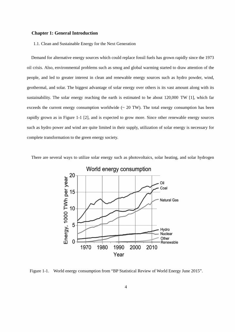
rapidly grown as in Figure 1-1 [2], and is expected to grow more. Since other renewable energy sources
such as hydro power and wind are quite limited in their supply, utilization of solar energy is necessary for
complete transformation to the green energy society.
There are several ways to utilize solar energy such as photovoltaics, solar heating, and solar hydrogen
Figure 1-1. World energy consumption from “BP Statistical Review of World Energy June 2015”.
5
production. Among these methods, the solar hydrogen production through photocatalytic and
photoelectrochemical water splitting is considered as a “Holy grail” for clean and sustainable energy
production. The concept of utilizing solar energy through water splitting was first presented in the paper by
Honda and collaborators published in 1975 [3]. Referring to their words, “the photo-cell produces
hydrogen, which can be a source of “clean energy”, through the decomposition of water by means of solar
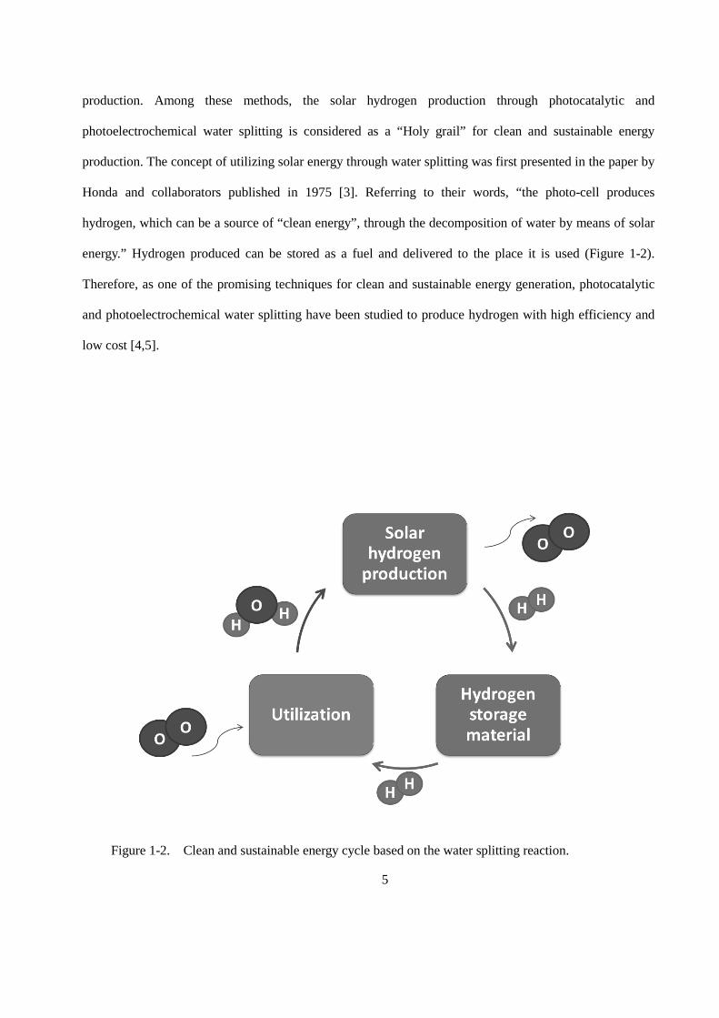
energy.” Hydrogen produced can be stored as a fuel and delivered to the place it is used (Figure 1-2).
Therefore, as one of the promising techniques for clean and sustainable energy generation, photocatalytic
and photoelectrochemical water splitting have been studied to produce hydrogen with high efficiency and
low cost [4,5].
Figure 1-2. Clean and sustainable energy cycle based on the water splitting reaction.
6
1.2. Required Properties for Photocatalytic Water Splitting
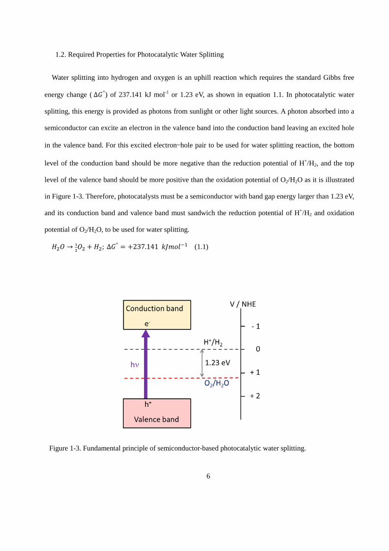
Water splitting into hydrogen and oxygen is an uphill reaction which requires the standard Gibbs free
energy change ( ∆𝐺𝐺°) of 237.141 kJ mol-1 or 1.23 eV, as shown in equation 1.1. In photocatalytic water
splitting, this energy is provided as photons from sunlight or other light sources. A photon absorbed into a
semiconductor can excite an electron in the valence band into the conduction band leaving an excited hole
in the valence band. For this excited electron—hole pair to be used for water splitting reaction, the bottom
level of the conduction band should be more negative than the reduction potential of H+/H2, and the top
level of the valence band should be more positive than the oxidation potential of O2/H2O as it is illustrated
in Figure 1-3. Therefore, photocatalysts must be a semiconductor with band gap energy larger than 1.23 eV,
and its conduction band and valence band must sandwich the reduction potential of H+/H2 and oxidation
potential of O2/H2O, to be used for water splitting.
𝐻𝐻2𝑂𝑂 → 12𝑂𝑂2 + 𝐻𝐻2; ∆𝐺𝐺° = +237.141 𝑘𝑘𝑘𝑘𝑘𝑘𝑘𝑘𝑘𝑘−1 (1.1)
Figure 1-3. Fundamental principle of semiconductor-based photocatalytic water splitting.
7
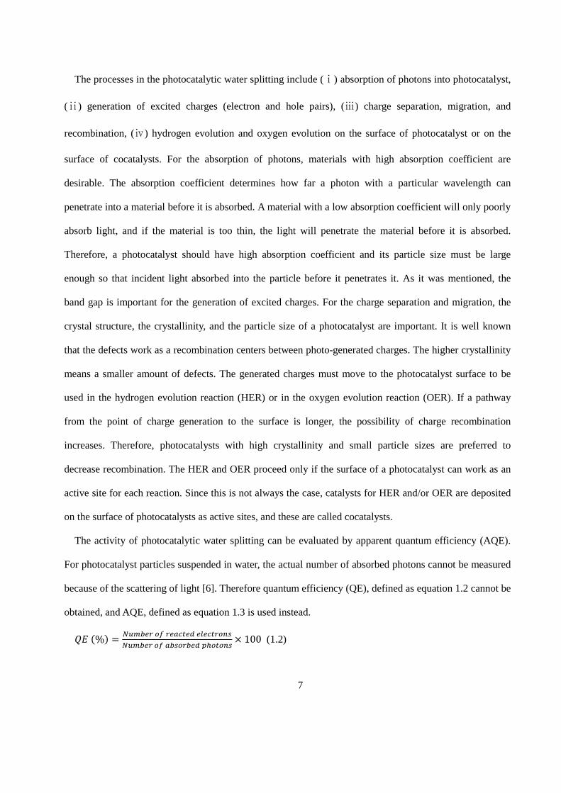
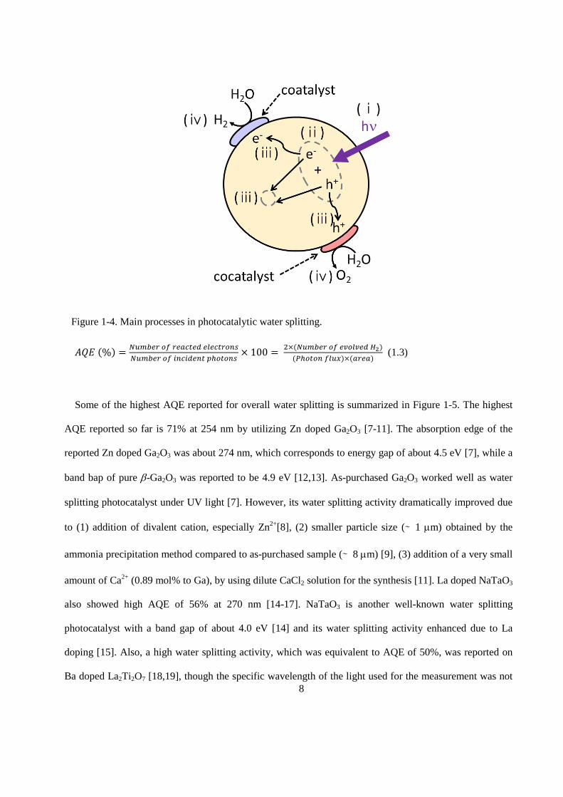
The processes in the photocatalytic water splitting include (ⅰ) absorption of photons into photocatalyst,
(ⅱ) generation of excited charges (electron and hole pairs), (ⅲ) charge separation, migration, and
recombination, (ⅳ) hydrogen evolution and oxygen evolution on the surface of photocatalyst or on the
surface of cocatalysts. For the absorption of photons, materials with high absorption coefficient are
desirable. The absorption coefficient determines how far a photon with a particular wavelength can
penetrate into a material before it is absorbed. A material with a low absorption coefficient will only poorly
absorb light, and if the material is too thin, the light will penetrate the material before it is absorbed.
Therefore, a photocatalyst should have high absorption coefficient and its particle size must be large
enough so that incident light absorbed into the particle before it penetrates it. As it was mentioned, the
band gap is important for the generation of excited charges. For the charge separation and migration, the
crystal structure, the crystallinity, and the particle size of a photocatalyst are important. It is well known
that the defects work as a recombination centers between photo-generated charges. The higher crystallinity
means a smaller amount of defects. The generated charges must move to the photocatalyst surface to be
used in the hydrogen evolution reaction (HER) or in the oxygen evolution reaction (OER). If a pathway
from the point of charge generation to the surface is longer, the possibility of charge recombination
increases. Therefore, photocatalysts with high crystallinity and small particle sizes are preferred to
decrease recombination. The HER and OER proceed only if the surface of a photocatalyst can work as an
active site for each reaction. Since this is not always the case, catalysts for HER and/or OER are deposited
on the surface of photocatalysts as active sites, and these are called cocatalysts.
The activity of photocatalytic water splitting can be evaluated by apparent quantum efficiency (AQE).
For photocatalyst particles suspended in water, the actual number of absorbed photons cannot be measured
because of the scattering of light [6]. Therefore quantum efficiency (QE), defined as equation 1.2 cannot be
obtained, and AQE, defined as equation 1.3 is used instead.
𝑄𝑄𝑄𝑄 (%) = 𝑁𝑁𝑁𝑁𝑁𝑁𝑁𝑁𝑁𝑁𝑁𝑁 𝑜𝑜𝑜𝑜 𝑁𝑁𝑁𝑁𝑟𝑟𝑟𝑟𝑟𝑟𝑁𝑁𝑟𝑟 𝑁𝑁𝑒𝑒𝑁𝑁𝑟𝑟𝑟𝑟𝑁𝑁𝑜𝑜𝑒𝑒𝑒𝑒𝑁𝑁𝑁𝑁𝑁𝑁𝑁𝑁𝑁𝑁𝑁𝑁 𝑜𝑜𝑜𝑜 𝑟𝑟𝑁𝑁𝑒𝑒𝑜𝑜𝑁𝑁𝑁𝑁𝑁𝑁𝑟𝑟 𝑝𝑝ℎ𝑜𝑜𝑟𝑟𝑜𝑜𝑒𝑒𝑒𝑒
× 100 (1.2)
8
𝐴𝐴𝑄𝑄𝑄𝑄 (%) = 𝑁𝑁𝑁𝑁𝑁𝑁𝑁𝑁𝑁𝑁𝑁𝑁 𝑜𝑜𝑜𝑜 𝑁𝑁𝑁𝑁𝑟𝑟𝑟𝑟𝑟𝑟𝑁𝑁𝑟𝑟 𝑁𝑁𝑒𝑒𝑁𝑁𝑟𝑟𝑟𝑟𝑁𝑁𝑜𝑜𝑒𝑒𝑒𝑒𝑁𝑁𝑁𝑁𝑁𝑁𝑁𝑁𝑁𝑁𝑁𝑁 𝑜𝑜𝑜𝑜 𝑖𝑖𝑒𝑒𝑟𝑟𝑖𝑖𝑟𝑟𝑁𝑁𝑒𝑒𝑟𝑟 𝑝𝑝ℎ𝑜𝑜𝑟𝑟𝑜𝑜𝑒𝑒𝑒𝑒
× 100 = 2×(𝑁𝑁𝑁𝑁𝑁𝑁𝑁𝑁𝑁𝑁𝑁𝑁 𝑜𝑜𝑜𝑜 𝑁𝑁𝑒𝑒𝑜𝑜𝑒𝑒𝑒𝑒𝑁𝑁𝑟𝑟 𝐻𝐻2)(𝑃𝑃ℎ𝑜𝑜𝑟𝑟𝑜𝑜𝑒𝑒 𝑜𝑜𝑒𝑒𝑁𝑁𝑓𝑓)×(𝑟𝑟𝑁𝑁𝑁𝑁𝑟𝑟)
(1.3)
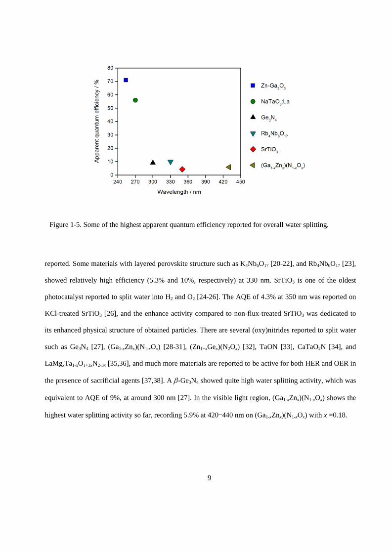
Some of the highest AQE reported for overall water splitting is summarized in Figure 1-5. The highest
AQE reported so far is 71% at 254 nm by utilizing Zn doped Ga2O3 [7-11]. The absorption edge of the
reported Zn doped Ga2O3 was about 274 nm, which corresponds to energy gap of about 4.5 eV [7], while a
band bap of pure β-Ga2O3 was reported to be 4.9 eV [12,13]. As-purchased Ga2O3 worked well as water
splitting photocatalyst under UV light [7]. However, its water splitting activity dramatically improved due
to (1) addition of divalent cation, especially Zn2+[8], (2) smaller particle size (∼ 1 µm) obtained by the
ammonia precipitation method compared to as-purchased sample (∼ 8 µm) [9], (3) addition of a very small
amount of Ca2+ (0.89 mol% to Ga), by using dilute CaCl2 solution for the synthesis [11]. La doped NaTaO3
also showed high AQE of 56% at 270 nm [14-17]. NaTaO3 is another well-known water splitting
photocatalyst with a band gap of about 4.0 eV [14] and its water splitting activity enhanced due to La
doping [15]. Also, a high water splitting activity, which was equivalent to AQE of 50%, was reported on
Ba doped La2Ti2O7 [18,19], though the specific wavelength of the light used for the measurement was not
Figure 1-4. Main processes in photocatalytic water splitting.
9
reported. Some materials with layered perovskite structure such as K4Nb6O17 [20-22], and Rb4Nb6O17 [23],
showed relatively high efficiency (5.3% and 10%, respectively) at 330 nm. SrTiO3 is one of the oldest
photocatalyst reported to split water into H2 and O2 [24-26]. The AQE of 4.3% at 350 nm was reported on
KCl-treated SrTiO3 [26], and the enhance activity compared to non-flux-treated SrTiO3 was dedicated to
its enhanced physical structure of obtained particles. There are several (oxy)nitrides reported to split water
such as Ge3N4 [27], (Ga1-xZnx)(N1-xOx) [28-31], (Zn1+xGex)(N2Ox) [32], TaON [33], CaTaO2N [34], and
LaMgxTa1-xO1+3xN2-3x [35,36], and much more materials are reported to be active for both HER and OER in
the presence of sacrificial agents [37,38]. A β-Ge3N4 showed quite high water splitting activity, which was
equivalent to AQE of 9%, at around 300 nm [27]. In the visible light region, (Ga1-xZnx)(N1-xOx) shows the
highest water splitting activity so far, recording 5.9% at 420—440 nm on (Ga1-xZnx)(N1-xOx) with x =0.18.
Figure 1-5. Some of the highest apparent quantum efficiency reported for overall water splitting.
10
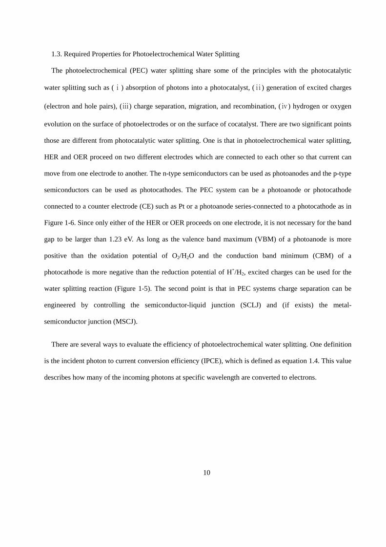
1.3. Required Properties for Photoelectrochemical Water Splitting
The photoelectrochemical (PEC) water splitting share some of the principles with the photocatalytic
water splitting such as (ⅰ) absorption of photons into a photocatalyst, (ⅱ) generation of excited charges
(electron and hole pairs), (ⅲ) charge separation, migration, and recombination, (ⅳ) hydrogen or oxygen
evolution on the surface of photoelectrodes or on the surface of cocatalyst. There are two significant points
those are different from photocatalytic water splitting. One is that in photoelectrochemical water splitting,
HER and OER proceed on two different electrodes which are connected to each other so that current can
move from one electrode to another. The n-type semiconductors can be used as photoanodes and the p-type
semiconductors can be used as photocathodes. The PEC system can be a photoanode or photocathode
connected to a counter electrode (CE) such as Pt or a photoanode series-connected to a photocathode as in
Figure 1-6. Since only either of the HER or OER proceeds on one electrode, it is not necessary for the band
gap to be larger than 1.23 eV. As long as the valence band maximum (VBM) of a photoanode is more
positive than the oxidation potential of O2/H2O and the conduction band minimum (CBM) of a
photocathode is more negative than the reduction potential of H+/H2, excited charges can be used for the
water splitting reaction (Figure 1-5). The second point is that in PEC systems charge separation can be
engineered by controlling the semiconductor-liquid junction (SCLJ) and (if exists) the metal-
semiconductor junction (MSCJ).
There are several ways to evaluate the efficiency of photoelectrochemical water splitting. One definition
is the incident photon to current conversion efficiency (IPCE), which is defined as equation 1.4. This value
describes how many of the incoming photons at specific wavelength are converted to electrons.
11
𝐼𝐼𝐼𝐼𝐼𝐼𝑄𝑄 (%) = 𝑁𝑁𝑁𝑁𝑁𝑁𝑁𝑁𝑁𝑁𝑁𝑁 𝑜𝑜𝑜𝑜 𝑁𝑁𝑒𝑒𝑁𝑁𝑟𝑟𝑟𝑟𝑁𝑁𝑜𝑜𝑒𝑒𝑒𝑒 𝑜𝑜𝑁𝑁𝑟𝑟𝑁𝑁𝑁𝑁𝑁𝑁𝑁𝑁𝑁𝑁𝑁𝑁 𝑜𝑜𝑜𝑜 𝑖𝑖𝑒𝑒𝑟𝑟𝑖𝑖𝑟𝑟𝑁𝑁𝑒𝑒𝑟𝑟 𝑝𝑝ℎ𝑜𝑜𝑟𝑟𝑜𝑜𝑒𝑒𝑒𝑒
× 100 = 𝐽𝐽𝑆𝑆𝑆𝑆𝑞𝑞Φ
= ℎ𝑟𝑟𝑞𝑞
× 𝐽𝐽𝑆𝑆𝑆𝑆𝜆𝜆×𝑃𝑃𝑖𝑖𝑖𝑖
(1.4)
1.4. Overview of Properties SrTiO3 as a Photocatalyst for Water Splitting
SrTiO3 is one of the oldest photocatalytic materials [24,39,40], accompanied by TiO2 [41,42]. On the
other hand, SrTiO3 also has been widely studied as different functional materials such as ferromagnetic
materials, optoelectric materials and others [43]. Therefore, compare to other newly developed
photocatalysts, physical, electrical, optical and chemical properties of SrTiO3 are quite well reported.
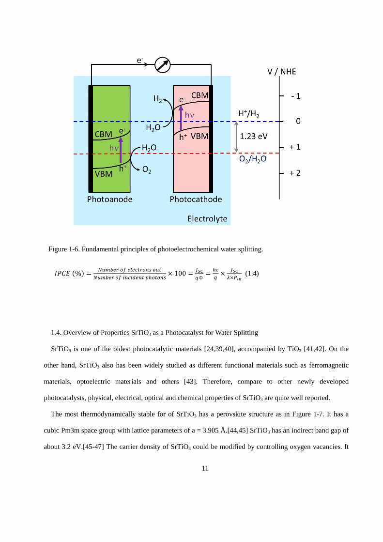
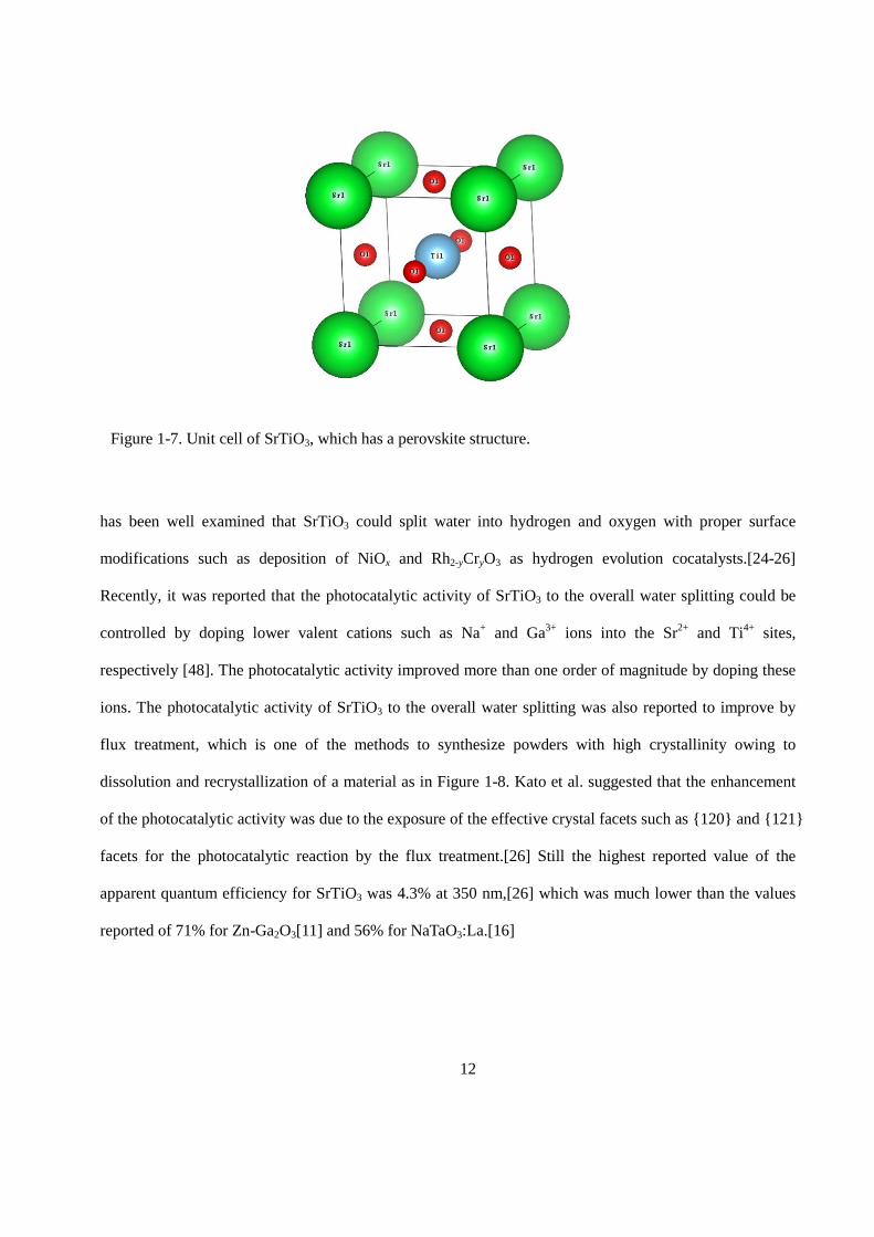
The most thermodynamically stable for of SrTiO3 has a perovskite structure as in Figure 1-7. It has a
cubic Pm3m space group with lattice parameters of a = 3.905 Å.[44,45] SrTiO3 has an indirect band gap of
about 3.2 eV.[45-47] The carrier density of SrTiO3 could be modified by controlling oxygen vacancies. It
Figure 1-6. Fundamental principles of photoelectrochemical water splitting.
12
has been well examined that SrTiO3 could split water into hydrogen and oxygen with proper surface
modifications such as deposition of NiOx and Rh2-yCryO3 as hydrogen evolution cocatalysts.[24-26]
Recently, it was reported that the photocatalytic activity of SrTiO3 to the overall water splitting could be
controlled by doping lower valent cations such as Na+ and Ga3+ ions into the Sr2+ and Ti4+ sites,
respectively [48]. The photocatalytic activity improved more than one order of magnitude by doping these
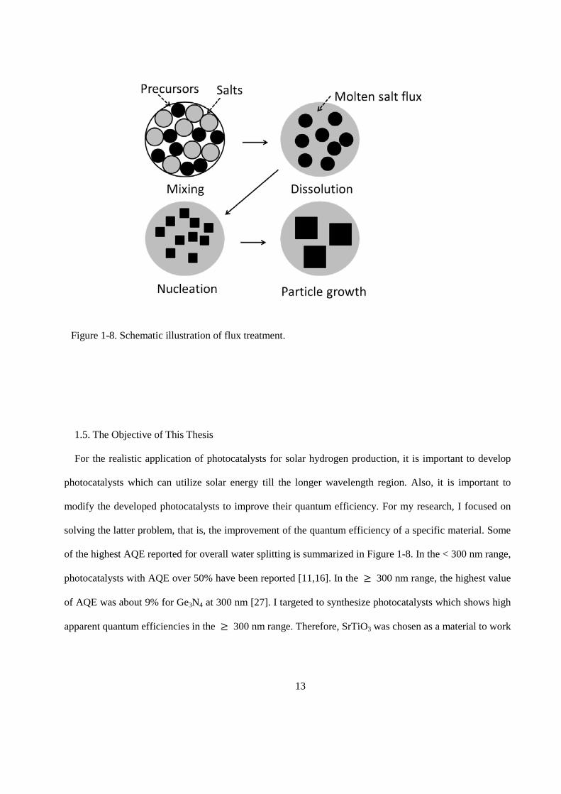
ions. The photocatalytic activity of SrTiO3 to the overall water splitting was also reported to improve by
flux treatment, which is one of the methods to synthesize powders with high crystallinity owing to
dissolution and recrystallization of a material as in Figure 1-8. Kato et al. suggested that the enhancement
of the photocatalytic activity was due to the exposure of the effective crystal facets such as {120} and {121}
facets for the photocatalytic reaction by the flux treatment.[26] Still the highest reported value of the
apparent quantum efficiency for SrTiO3 was 4.3% at 350 nm,[26] which was much lower than the values
reported of 71% for Zn-Ga2O3[11] and 56% for NaTaO3:La.[16]
Figure 1-7. Unit cell of SrTiO3, which has a perovskite structure.
13
1.5. The Objective of This Thesis
For the realistic application of photocatalysts for solar hydrogen production, it is important to develop
photocatalysts which can utilize solar energy till the longer wavelength region. Also, it is important to
modify the developed photocatalysts to improve their quantum efficiency. For my research, I focused on
solving the latter problem, that is, the improvement of the quantum efficiency of a specific material. Some
of the highest AQE reported for overall water splitting is summarized in Figure 1-8. In the < 300 nm range,
photocatalysts with AQE over 50% have been reported [11,16]. In the ≥ 300 nm range, the highest value
of AQE was about 9% for Ge3N4 at 300 nm [27]. I targeted to synthesize photocatalysts which shows high
apparent quantum efficiencies in the ≥ 300 nm range. Therefore, SrTiO3 was chosen as a material to work
Figure 1-8. Schematic illustration of flux treatment.
14
with because properties as a water splitting photocatalyst had already been reported. As a method to
improve water splitting activity of SrTiO3, metal ion doping and flux treatment were applied in my work.
Using the obtained SrTiO3 photocatalyst particles, electrodes were prepared by the particle transfer
method.[49] The properties of the electrodes prepared from SrTiO3 particles with different photocatalytic
properties and those made of single crystalline wafers of SrTiO3 were compared, so that the potential of the
electrodes prepared from the particles could be evaluated. Also, differences and similarities of the
photocatalytic and photoelectrochemical water splitting were discussed.
1.6. General Experimental Procedures
1.6.1. Measurement of Photocatalytic Activity of SrTiO3 Powder
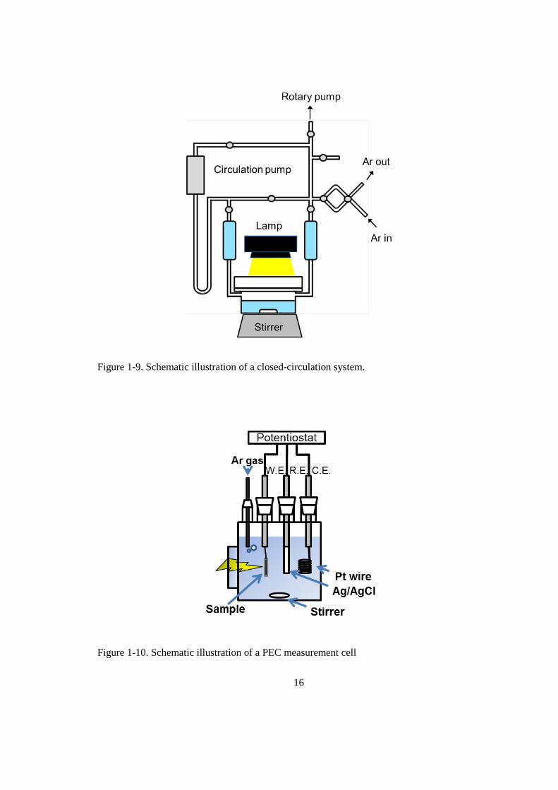
The activities of the photocatalyst samples were tested in a closed gas circulation system with a top-
irradiation-type reactor as shown in Figure 1-9. The deionized water (100 mL) was evacuated to remove air
completely. The reactor was irradiated using a 300 W xenon lamp (λ >300 nm) through a quartz window
or using a 450 W high-pressure mercury lamp through a quartz cooling jacket and, when necessary, a 2-cm
diameter slit, a band pass filter (λ = 360 nm, FWHM = 10 nm), and a series of neutral density filters (OD =
0.3, 0.5, 1.0, and 2.0) to irradiate the sample with monochromatic light with controlled intensity. The
intensity of the irradiated monochromatic light was measured with a silicon photodiode. The evolved gases
were analyzed by a gas chromatograph (Shimadzu, GC-8A) equipped with a thermal conductivity detector,
using Ar as a carrier gas.
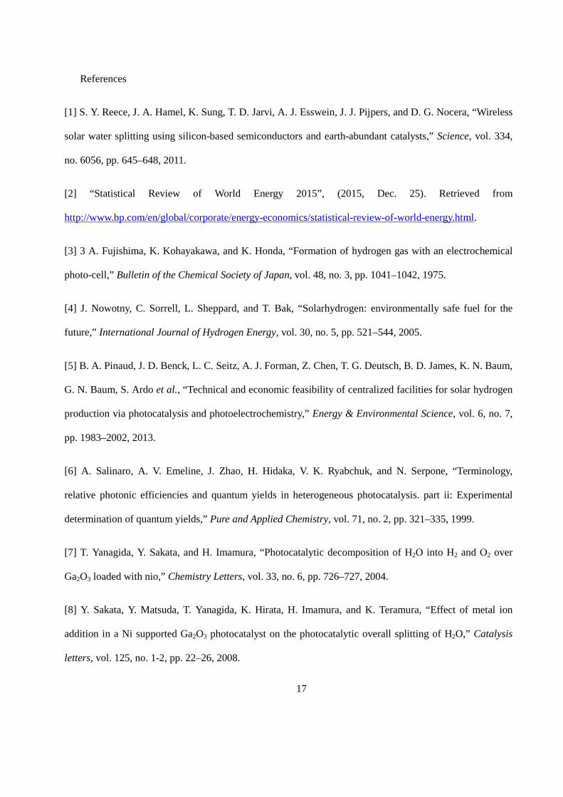
1.6.2. Photoelectrochemical Measurements
Photoelectrochemical (PEC) properties were measured by a typical 3-electrode setup as shown in Figure
1-10. The prepared electrode, an Ag/AgCl electrode in 3 M NaCl aqueous solution, and a Pt wire were
connected to a potentiostat (HSV-100; Hokuto Denko Corp.) as working, reference, and counter electrodes,
respectively. A 300 W xenon lamp (λ >300 nm) was used as a light source. When necessary, a
15
monochromator (CT-10) was set in front of the xenon lamp to irradiate monochromatic light. All PEC
measurements were performed under an Ar atmosphere.
1.6.3. Sample Characterization
The crystal structures of the products were characterized by X-ray diffractometry (XRD; RINT Ultima
III, Rigaku Co.) using Cu Kα radiation at 40 kV and 40 mA. XRD peaks due to Cu Kα1 and K α2 radiation
were deconvoluted and the full width at half maximum (FWHM) of the (110) peak due to the Cu Kα1
radiation was estimated. Specific surface areas were measured with a Belsorp-miniII (BEL Japan Inc.). The
morphology of the powder was observed by scanning electron microscopy (SEM; S-4700, Hitachi High-
Technologies Co.). Ultraviolet-visible diffuse reflectance spectrometry (DRS; V-670, Jasco Co.) was
performed using spectralon (Jasco Co.) as a reference material. The surface states of the materials were
examined by X-ray photoelectron spectroscopy (XPS; JPS-9000, Jeol Ltd.) using Mg Kα radiation. The
binding energies were corrected using the binding energy of adventitious carbon (C1s, 284.6 eV).
Inductively coupled plasma optical emission spectroscopy (ICP-OES; Shimadzu Co., ICPS-8100) was used
for elemental analysis. SrTiO3 powder (0.01 g) was melted with 1.0 g of a 3:1 mixture of Na2CO3 and
B(OH)3 by heating. An aqueous solution of tartaric acid (5%, 10 mL), HCl (1+1, 4 mL), and H2O2 (30 wt%,
1 mL) were added to dissolve the melt, and diluted with distilled water to make the total volume 100 mL.
The resulting solution was used to measure Al and Y. The solution was further diluted tenfold to measure
Sr and Ti.
16
Figure 1-9. Schematic illustration of a closed-circulation system.
Figure 1-10. Schematic illustration of a PEC measurement cell
17
References
[1] S. Y. Reece, J. A. Hamel, K. Sung, T. D. Jarvi, A. J. Esswein, J. J. Pijpers, and D. G. Nocera, “Wireless
solar water splitting using silicon-based semiconductors and earth-abundant catalysts,” Science, vol. 334,
no. 6056, pp. 645–648, 2011.
[2] “Statistical Review of World Energy 2015”, (2015, Dec. 25). Retrieved from
http://www.bp.com/en/global/corporate/energy-economics/statistical-review-of-world-energy.html.
[3] 3 A. Fujishima, K. Kohayakawa, and K. Honda, “Formation of hydrogen gas with an electrochemical
photo-cell,” Bulletin of the Chemical Society of Japan, vol. 48, no. 3, pp. 1041–1042, 1975.
[4] J. Nowotny, C. Sorrell, L. Sheppard, and T. Bak, “Solarhydrogen: environmentally safe fuel for the
future,” International Journal of Hydrogen Energy, vol. 30, no. 5, pp. 521–544, 2005.
[5] B. A. Pinaud, J. D. Benck, L. C. Seitz, A. J. Forman, Z. Chen, T. G. Deutsch, B. D. James, K. N. Baum,
G. N. Baum, S. Ardo et al., “Technical and economic feasibility of centralized facilities for solar hydrogen
production via photocatalysis and photoelectrochemistry,” Energy & Environmental Science, vol. 6, no. 7,
pp. 1983–2002, 2013.
[6] A. Salinaro, A. V. Emeline, J. Zhao, H. Hidaka, V. K. Ryabchuk, and N. Serpone, “Terminology,
relative photonic efficiencies and quantum yields in heterogeneous photocatalysis. part ii: Experimental
determination of quantum yields,” Pure and Applied Chemistry, vol. 71, no. 2, pp. 321–335, 1999.
[7] T. Yanagida, Y. Sakata, and H. Imamura, “Photocatalytic decomposition of H2O into H2 and O2 over
Ga2O3 loaded with nio,” Chemistry Letters, vol. 33, no. 6, pp. 726–727, 2004.
[8] Y. Sakata, Y. Matsuda, T. Yanagida, K. Hirata, H. Imamura, and K. Teramura, “Effect of metal ion
addition in a Ni supported Ga2O3 photocatalyst on the photocatalytic overall splitting of H2O,” Catalysis
letters, vol. 125, no. 1-2, pp. 22–26, 2008.
18
[9] Y. Sakata, Y. Matsuda, T. Nakagawa, R. Yasunaga, H. Imamura, and K. Teramura, “Remarkable
improvement of the photocatalytic activity of Ga2O3 towards the overall splitting of H2O,” ChemSusChem,
vol. 4, no. 2, pp. 181–184, 2011.
[10] Y. Sakata, T. Nakagawa, Y. Nagamatsu, Y. Matsuda, R. Yasunaga, E. Nakao, and H. Imamura,
“Photocatalytic properties of gallium oxides prepared by precipitation methods toward the overall splitting
of H2O,” Journal of Catalysis, vol. 310, pp. 45–50, 2014.
[11] Y. Sakata, T. Hayashi, R. Yasunaga, N. Yanaga, and H. Imamura, “Remarkably high apparent quantum
yield of the overall photocatalytic H2O splitting achieved by utilizing Zn ion added Ga2O3 prepared using
dilute CaCl2 solution,” Chemical Communications, vol. 51, no. 65, pp. 12 935–12 938, 2015.
[12] M. Orita, H. Ohta, M. Hirano, and H. Hosono, “Deep-ultraviolet transparent conductive β-Ga2O3 thin
films,” Applied Physics Letters, vol. 77, p. 4166, 2000–4168.
[13] M. Mohamed, C. Janowitz, I. Unger, R. Manzke, Z. Galazka, R. Uecker, R. Fornari, J. R.Weber, J. B.
Varley, and C. G. Van de Walle, “The electronic structure of β-Ga2O3,” Applied Physics Letters, vol. 97, no.
21, p. 211903, 2010.
[14] H. Kato and A. Kudo, “Highly efficient decomposition of pure water into H2 and O2 over NaTaO3
photocatalysts,” Catalysis letters, vol. 58, no. 2-3, pp. 153–155, 1999.
[15] A. Kudo and H. Kato, “Effect of lanthanide-doping into NaTaO3 photocatalysts for efficient water
splitting,” Chemical Physics Letters, vol. 331, no. 5, pp. 373–377, 2000.
[16] H. Kato, K. Asakura, and A. Kudo, “Highly efficient water splitting into H2 and O2 over lanthanum-
doped NaTaO3 photocatalysts with high crystallinity and surface nanostructure,” Journal of the American
Chemical Society, vol. 125, no. 10, pp.3082–3089, 2003.
19
[17] A. Iwase, H. Kato, H. Okutomi, and A. Kudo, “Formation of surface nano-step structures and
improvement of photocatalytic activities of NaTaO3 by doping of alkaline earth metal ions,” Chemistry
Letters, vol. 33, no. 10, pp. 1260–1261, 2004.
[18] H. Kim, D. Hwang, Y. Kim, J. Lee et al., “Highly donor-doped (110) layered perovskite materials as
novel photocatalysts for overall water splitting,” Chemical Communications, no. 12, pp. 1077–1078, 1999.
[19] J. Kim, D. W. Hwang, H. G. Kim, S. W. Bae, J. S. Lee, W. Li, and S. H. Oh, “Highly efficient overall
water splitting through optimization of preparation and operation conditions of layered perovskite
photocatalysts,” Topics in Catalysis, vol. 35, no. 3-4, pp. 295–303, 2005.
[20] A. Kudo, A. Tanaka, K. Domen, K. Maruya, K. Aika, and T. Onishi, “Photocatalytic decomposition of
water over NiO-K4Nb6O17 catalyst,” Journal of catalysis, vol. 111, no. 1, pp. 67–76, 1988.
[21] A. Kudo, K. Sayama, A. Tanaka, K. Asakura, K. Domen, K. Maruy, and T. Onishi, “Nickel-loaded
K4Nb6O17 photocatalyst in the decomposition of H2O into H2 and O2: Structure and reaction mechanism,”
Journal of catalysis, vol. 120, no. 2, pp. 337–352, 1989.
[22] K. Sayama, A. Tanaka, K. Domen, K. Maruya, and T. Onishi, “Improvement of nickel-loaded
K4Nb6O17 photocatalyst for the decomposition of H2O,” Catalysis letters, vol. 4, no. 3, pp. 217–222, 1990.
[23] K. Sayama, A. Tanaka, K. Domen, K. Maruya, and T. Onishi, “Photocatalytic decomposition of water
over a Ni-loaded Rb4Nb6O17 atalyst,” Journal of Catalysis, vol. 124, no. 2, pp. 541–547, 1990.
[24] K. Domen, S. Naito, M. Soma, T. Onishi, and K. Tamaru, “Photocatalytic decomposition of water
vapour on an NiO–SrTiO3 catalyst,” Journal of the Chemical Society, Chemical Communications, no. 12,
pp. 543–544, 1980.
20
[25] K. Domen, A. Kudo, T. Onishi, N. Kosugi, and H. Kuroda, “Photocatalytic decomposition of water
into hydrogen and oxygen over nickel (ii) oxide-strontium titanate (SrTiO3) powder. 1. structure of the
catalysts,” The Journal of Physical Chemistry, vol. 90, no. 2, pp. 292–295, 1986.
[26] H. Kato, M. Kobayashi, M. Hara, and M. Kakihana, “Fabrication of SrTiO3 exposing characteristic
facets using molten salt flux and improvement of photocatalytic activity for water splitting,” Catalysis
Science & Technology, vol. 3, no. 7, pp. 1733–1738, 2013.
[27] J. Sato, N. Saito, Y. Yamada, K. Maeda, T. Takata, J. N. Kondo, M. Hara, H. Kobayashi, K. Domen,
and Y. Inoue, “RuO2-loaded β-Ge3N4 as a non-oxide photocatalyst for overall water splitting,” Journal of
the American Chemical Society, vol. 127,no. 12, pp. 4150–4151, 2005.
[28] K. Maeda, T. Takata, M. Hara, N. Saito, Y. Inoue, H. Kobayashi, and K. Domen, “GaN:ZnO solid
solution as a photocatalyst for visible-light-driven overall water splitting,” Journal of the American
Chemical Society, vol. 127, no. 23, pp. 8286–8287, 2005.
[29] K. Maeda, K. Teramura, T. Takata, M. Hara, N. Saito, K. Toda, Y. Inoue, H. Kobayashi, and K. Domen,
“Overall water splitting on (Ga1-xZnx)(N1-xOx) solid solution photocatalyst: Relationship between physical
properties and photocatalytic activity,” The Journal of Physical Chemistry B, vol. 109, no. 43, pp. 20 504–
20 510, 2005.
[30] K. Maeda, K. Teramura, D. Lu, T. Takata, N. Saito, Y. Inoue, and K. Domen, “Photocatalyst releasing
hydrogen from water,” Nature, vol. 440, no. 7082, pp. 295–295, 2006.
[31] K. Maeda, K. Teramura, and K. Domen, “Effect of postcalcination on photocatalytic activity of (Ga1-
xZnx)(N1-xOx) solid solution for overall water splitting under visible light,” Journal of catalysis, vol. 254, no.
2, pp. 198–204, 2008.
21
[32] Y. Lee, H. Terashima, Y. Shimodaira, K. Teramura, M. Hara, H. Kobayashi, K. Domen, and M.
Yashima, “Zinc germanium oxynitride as a photocatalyst for overall water splitting under visible light,”
The Journal of Physical Chemistry C, vol. 111, no. 2, pp. 1042–1048, 2007.
[33] K. Maeda, D. Lu, and K. Domen, “Direct water splitting into hydrogen and oxygen under visible light
by using modified TaON photocatalysts with d0 electronic configuration,” Chemistry-A European Journal,
vol. 19, no. 16, pp. 4986–4991, 2013.
[34] J. Xu, C. Pan, T. Takata, and K. Domen, “Photocatalytic overall water splitting on the perovskite-type
transition metal oxyni-tride CaTaO2N under visible light irradiation,” Chemical Communications, vol. 51,
no. 33, pp. 7191–7194, 2015.
[35] C. Pan, T. Takata, M. Nakabayashi, T. Matsumoto, N. Shibata, Y. Ikuhara, and K. Domen, “A complex
perovskite-type oxynitride: The first photocatalyst for water splitting operable at up to 600 nm,”
Angewandte Chemie International Edition, vol. 54, no. 10, pp. 2955–2959, 2015.
[36] C. Pan, T. Takata, and K. Domen, “Overall water splitting on the transition-metal oxynitride
photocatalyst LaMg1/3Ta2/3O2N over a large portion of the visible-light spectrum,” Chemistry–A European
Journal, 2015, doi: http://dx.doi.org/10.1002/chem.201504376.
[37] A. Kudo and Y. Miseki, “Heterogeneous photocatalyst materials for water splitting,” Chemical Society
Reviews, vol. 38, no. 1, pp. 253–278, 2009.
[38] X. Chen, S. Shen, L. Guo, and S. S. Mao, “Semiconductorbased photocatalytic hydrogen generation,”
Chemical reviews, vol. 110, no. 11, pp. 6503–6570, 2010.
[39] T. Watanabe, A. Fujishima, and K. Honda, “Photoelectrochemical reactions at SrTiO3 single crystal
electrode,” Bulletin of the Chemical Society of Japan, vol. 49, no. 2, pp. 355–358, 1976.
22
[40] A. Fujishima and K. Honda, “Electrochemical evidence for the mechanism of the primary stage of
photosynthesis,” Bulletin of the chemical society of Japan, vol. 44, no. 4, pp. 1148–1150, 1971.
[41] A. Fujishima and K. Honda, “Electrochemical photolysis of water at a semiconductor electrode,”
Nature, vol. 238, pp. 37–38, 1972.
[42] R. Waser, R. Dittmann, G. Staikov, and K. Szot, “Redoxbased resistive switching memories–
nanoionic mechanisms, prospects, and challenges,” Advanced Materials, vol. 21, no. 25-26, pp. 2632–2663,
2009.
[43] H. D. Megaw, “Crystal structure of double oxides of the perovskite type,” Proceedings of the Physical
Society, vol. 58, no. 2, p. 133, 1946.
[44] R. Cowley, “Lattice dynamics and phase transitions of strontium titanate,” Physical Review, vol. 134,
no. 4A, p. A981, 1964.44 A. Kahn and A. Leyendecker, “Electronic energy bands in strontium titanate,”
Physical Review, vol. 135, no. 5A, p.A1321, 1964.
[45] M. Capizzi and A. Frova, “Optical gap of strontium titanate (deviation from urbach tail behavior),”
Physical Review Letters, vol. 25, no. 18, p. 1298, 1970.
[46] K. Van Benthem, C. Elsässer, and R. French, “Bulk electronic structure of SrTiO3: Experiment and
theory,” Journal of Applied Physics, vol. 90, no. 12, pp. 6156–6164, 2001.
[47] T. Takata and K. Domen, “Defect engineering of photocatalysts by doping of aliovalent metal cations
for efficient water splitting,” The Journal of Physical Chemistry C, vol. 113, no. 45, pp. 19 386–19 388,
2009.
[48] T. Minegishi, N. Nishimura, J. Kubota, and K. Domen, “Photoelectrochemical properties of LaTiO2N
electrodes prepared by particle transfer for sunlight-driven water splitting,” Chemical Science, vol. 4, no. 3,
pp. 1120–1124, 2013.
23
Chapter 2: Modification of SrTiO3 Particles with Cation Doping and/or Flux Treatment
for Efficient Overall Water Splitting
2.1. Introduction
Photocatalytic water splitting is an important and fundamental photocatalytic reaction and has attracted
much attention as a means of H2 production from water under solar irradiation. A lot of studies have been
performed to develop effective photocatalysts for overall water splitting. As a result, various types of
photocatalysts have been developed. However, in most cases, the photocatalytic activity is too low for
further applications. Some wide band gap oxide photocatalysts exhibit high apparent quantum efficiencies
in the overall water splitting reaction but only under ultraviolet irradiation. Other visible-light-driven
photocatalysts such as (oxy)nitrides[1-5] can split water under visible light but at low quantum efficiencies.
Therefore, further investigations are necessary to improve the photocatalytic activity.
Studies reporting high apparent quantum efficiencies in the water splitting reaction are summarized in
Figure 1-5. Zn ion added Ga2O3 combined with the Rh0.5Cr1.5O3 cocatalyst was reported to show the
remarkably high photocatalytic activity to the overall water splitting under UV light.[6-8] Particularly,
when Ga2O3 was prepared in dilute CaCl2 solution, the photocatalytic activity was further improved. The
apparent quantum yield was reported to be 71% at 254 nm.[8] In the case of a NaTaO3 photocatalyst, the
photocatalytic activity was remarkably improved by doping La ions.[9,10] Here, the apparent quantum
yield of the photocatalytic overall water splitting was reported to be 56% under the irradiation at 270
nm.[10] In both cases, added metal ions played significant roles for improving the photocatalytic activity.
Therefore, the addition of metal ions to the photocatalytic materials is one of the effective ways for
improving the photocatalytic activity of overall water splitting.
Highly crystalline particles can be obtained by using a flux as a growth medium. The flux method,
which allows the growth of crystalline particles via dissolution and recrystallization of solutes driven by
supersaturation, has been applied to the synthesis of metal oxides, including semiconducting oxides, such
24
as K4Nb6O17,[11] KNb3O8,[12] Na2Ti6O13,[13] K2Ti6O13,[14] and SnNb2O6.[15] Some of these oxides
showed improved photocatalytic activity compared to those prepared by other synthesis methods. Some
semiconducting (oxy)nitride photocatalysts such as LaTiO2N,[16] C3N4,[17] and Ta3N5[18] have also been
prepared with the aid of a flux. However, the downside of this method is the incorporation of impurities
into the target material, a commonly observed phenomenon during flux treatment.[19,20] On the other
hand, doping can often change the particle morphology dramatically and create mid-gap states essential for
visible light activity of some wide-bandgap oxides. In fact, the high activity of NaTaO3 and the visible
light activity of SrTiO3 photocatalysts rely on such doping effects. Recently, much effort has been made to
understand the effect of doping in terms of carrier dynamics. From the material synthesis standpoint, the
challenges in the activation of photocatalysts lie in how to lower defect densities, reduce particle sizes, and
incorporate dopants effectively. The flux treatment of photocatalytic materials may offer a solution to such
challenges.
SrTiO3 is a classic photocatalyst that has been reported to be active in overall water splitting under UV
light since 1980[21] and is still widely investigated in fundamental studies on the effects of doping,[22-25]
particle morphology,[26] and cocatalysts.[27] In a recent study, Takata et al. found that doping of lower-
valence cations in SrTiO3, such as Na+ into Sr2+ and Ga3+ into Ti4+, dramatically enhanced the
photocatalytic activity during the overall water splitting reaction.[24] This positive effect of doping could
be attributed to the lower density of trivalent Ti states. Thus, the effects of the incorporation of even a
small amount of impurity into SrTiO3 during the flux treatment should be carefully investigated.
In this chapter, the effects of SrCl2 flux treatment and cation doping on the physical properties and
photocatalytic activity of SrTiO3 were investigated.
25
2.2. Experimental Section
2.2.1. As-purchased SrTiO3
SrTiO3 (Wako Pure Chemicals Industries, Ltd., 99.9%) was employed as a raw material without any
post-treatment (hereafter STO(wako)).
2.2.2. Flux Treatment on SrTiO3
NaCl(Wako Pure Chemicals Industries, Ltd., 99.9%), KCl(Wako Pure Chemicals Industries, Ltd.,
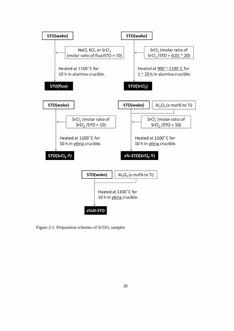
99.9%), and SrCl2 (Kanto Chemicals Co., Inc., 98.0%, anhydrous) were used as flux. As it is represented in
Figure 2-1, STO(wako) and each of flux materials were thoroughly mixed in an agate mortar with molar
ratio of flux/SrTiO3 = 10. The mixture was heated in an alumina crucible at 1100 °C for 10 h. After the
mixture was cooled to room temperature, SrTiO3 was separated from the solidified mass by repeated
washing with deionized water until no white AgCl precipitate formed in rinse solutions upon adding
AgNO3. The final product of flux-treated SrTiO3 will hereafter referred to as STO(flux) where flux
represents type of flux material used.
2.2.3. SrCl2 Treatment on SrTiO3
For STO(SrCl2), treatment conditions were examined in detail. First, the molar ratio of SrCl2/STO was
varied from 0.01 to 20. Second, the treatment temperature was varied from 900 to 1100 °C. Third, the
soaking time was varied from 1 to 20 hours. At last, the cooling rate to 500 °C was varied from 6 K min-1
to natural cooling. The same procedures explained in section 2.2.2 were applied except for the steps
mentioned above.
2.2.4. SrCl2 Treatment on SrTiO3 in Yttria Crucibles
Al2O3 (Sigma-Aldrich Co, LLC., nanopowder), and SrCl2 (Kanto Chemicals Co., Inc., 98.0%, anhydrous)
were used as raw materials. STO(wako), Al2O3 (when used), and SrCl2 were thoroughly mixed in an agate
26
mortar. The mixture was heated either in an yttria crucible at 1100 °C for 10 h. The SrTiO3 samples treated
in yttria crucibles will hereafter be referred to as STO(SrCl2-Y), where -Y was used to highlight the use of
yttria crucibles. The STO(SrCl2-Y) samples with Al2O3 addition will hereafter be referred to as x%Al-
STO(SrCl2-Y), where x% represents the Al/Ti molar ratio in the starting mixture.
2.2.5. Al-doping on SrTiO3
Al2O3 (Sigma-Aldrich Co, LLC., nanopowder) and SrCl2 (Kanto Chemicals Co., Inc., 98.0%, anhydrous)
were used as raw materials. STO(wako) and Al2O3 were thoroughly mixed in an agate mortar. The mixture
was heated in an yttria crucible at 1100 °C for 10 h. These samples will hereafter be referred to as x%Al-
STO, where x% represents the Al/Ti molar ratio in the starting mixture.
2.2.6. Polymerizable Complex Method
In a polymerizable complex method, SrCO3, titanium isopropoxide, citric acid and ethylene glycol
(Wako Pure Chemicals Industries, Ltd.,) were used as starting materials. Equimolar amounts of SrCO3 and
titanium isopropoxide were dissolved in methanol containing citric acid and ethylene glycol. The molar
ratio of SrCO3 : titanium tetoraisopropoxide : citric acid : ethylene glycol was 1 : 1 : 4 : 10 The
polymerization of citrates with ethylene glycol was performed under reflux at 458 K for 2 h. The pyrolysis
of the polymerized metal complexes was carried out at 623 K for 12 h in air to obtain a carbonized powder.
The carbonized sample was finally calcined at 1273 K for 10 h to prepare STO(PC).
2.2.7. Metal Ion Addition
The addition of metal ion was carried out by an impregnation method using suspension of the SrTiO3
powder in an aqueous solution of desired metal salts. The obtained composite of metal salts and SrTiO3
was calcined at 1273 K in air to prepare metal ion added SrTiO3. Here, Li2CO3, Na2CO3, K2CO3, Rb2CO3,

27
Cs2CO3, Mg(NO3)2, Zn(NO3)2, Ca(NO3)2, Ba(NO3)2, Al(NO3)3, Ga(NO3)3, In(NO3)3, Y(NO3)3 and
La(NO3)3 (Wako pure chemical) were used as the source of the added metal ions.
2.2.8. Loading of Cocatalyst
As a cocatalyst, mixed oxide of rhodium and chromium, Rh2-yCryO3, was loaded by an impregnation
method.[28] The SrTiO3 samples were loaded with Na3RhCl6·nH2O (Rh 17.8 wt%) and Cr(NO3)3·9H2O
(98.0~103.0%) as Rh and Cr sources, respectively, and calcined in air at 350 °C for 1 h.
2.2.9. Sample Characterization
Photocatalytic water splitting activity and physical properties of the samples were evaluated according
to the procedures described in Section 1.6.1 and 1.6.3, respectively.
28
Figure 2-1. Preparation schemes of SrTiO3 samples
29
2.3. Results and Discussion
2.3.1. Characterization of Flux-Treated SrTiO3 Particles
On the basis of the preceding study by Kato et al. reporting that flux-treated SrTiO3 shows improvement
in their water splitting activity, as-purchased SrTiO3, STO(wako), was treated with NaCl, KCl, and SrCl2,
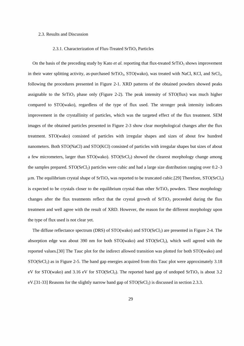
following the procedures presented in Figure 2-1. XRD patterns of the obtained powders showed peaks
assignable to the SrTiO3 phase only (Figure 2-2). The peak intensity of STO(flux) was much higher
compared to STO(wako), regardless of the type of flux used. The stronger peak intensity indicates
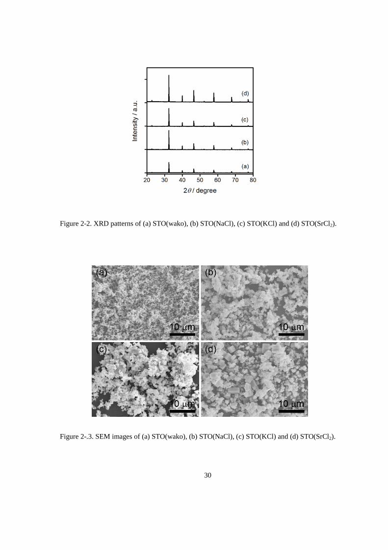
improvement in the crystallinity of particles, which was the targeted effect of the flux treatment. SEM
images of the obtained particles presented in Figure 2-3 show clear morphological changes after the flux
treatment. STO(wako) consisted of particles with irregular shapes and sizes of about few hundred
nanometers. Both STO(NaCl) and STO(KCl) consisted of particles with irregular shapes but sizes of about
a few micrometers, larger than STO(wako). STO(SrCl2) showed the clearest morphology change among
the samples prepared. STO(SrCl2) particles were cubic and had a large size distribution ranging over 0.2–3
µm. The equilibrium crystal shape of SrTiO3 was reported to be truncated cubic.[29] Therefore, STO(SrCl2)
is expected to be crystals closer to the equilibrium crystal than other SrTiO3 powders. These morphology
changes after the flux treatments reflect that the crystal growth of SrTiO3 proceeded during the flux
treatment and well agree with the result of XRD. However, the reason for the different morphology upon
the type of flux used is not clear yet.
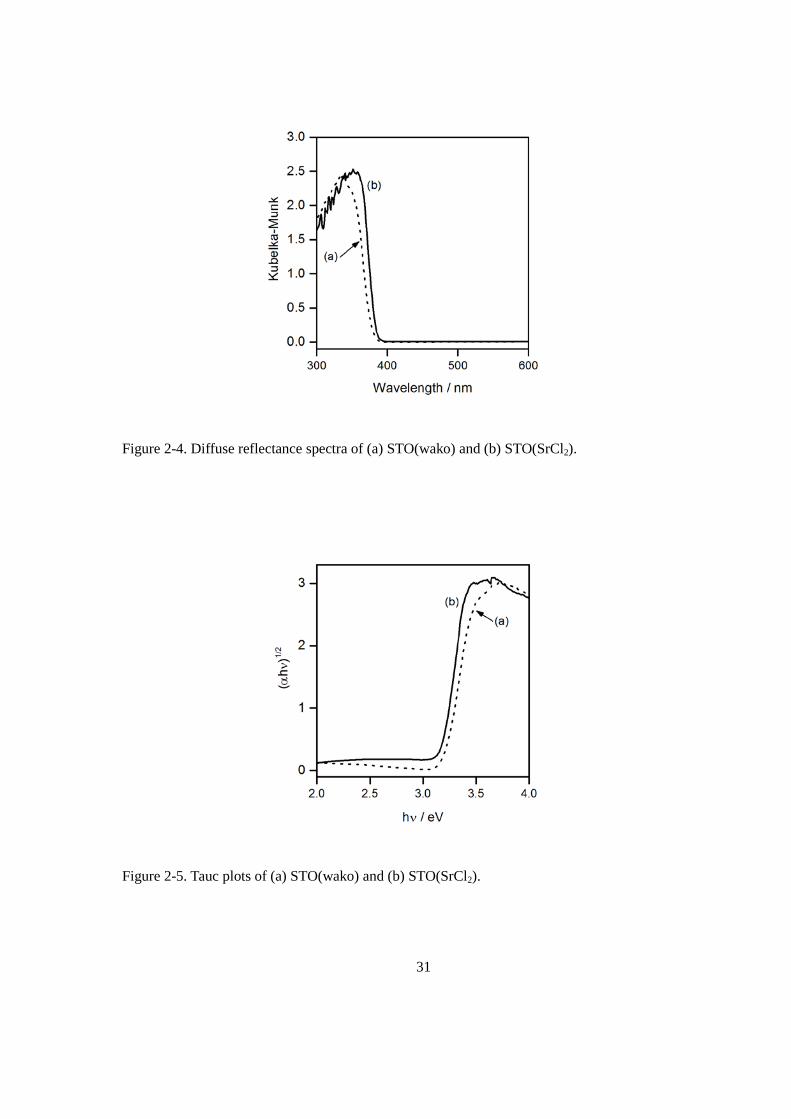
The diffuse reflectance spectrum (DRS) of STO(wako) and STO(SrCl2) are presented in Figure 2-4. The
absorption edge was about 390 nm for both STO(wako) and STO(SrCl2), which well agreed with the
reported values.[30] The Tauc plot for the indirect allowed transition was plotted for both STO(wako) and
STO(SrCl2) as in Figure 2-5. The band gap energies acquired from this Tauc plot were approximately 3.18
eV for STO(wako) and 3.16 eV for STO(SrCl2). The reported band gap of undoped SrTiO3 is about 3.2
eV.[31-33] Reasons for the slightly narrow band gap of STO(SrCl2) is discussed in section 2.3.3.
30
Figure 2-2. XRD patterns of (a) STO(wako), (b) STO(NaCl), (c) STO(KCl) and (d) STO(SrCl2).
Figure 2-.3. SEM images of (a) STO(wako), (b) STO(NaCl), (c) STO(KCl) and (d) STO(SrCl2).
31
Figure 2-4. Diffuse reflectance spectra of (a) STO(wako) and (b) STO(SrCl2).
Figure 2-5. Tauc plots of (a) STO(wako) and (b) STO(SrCl2).
32
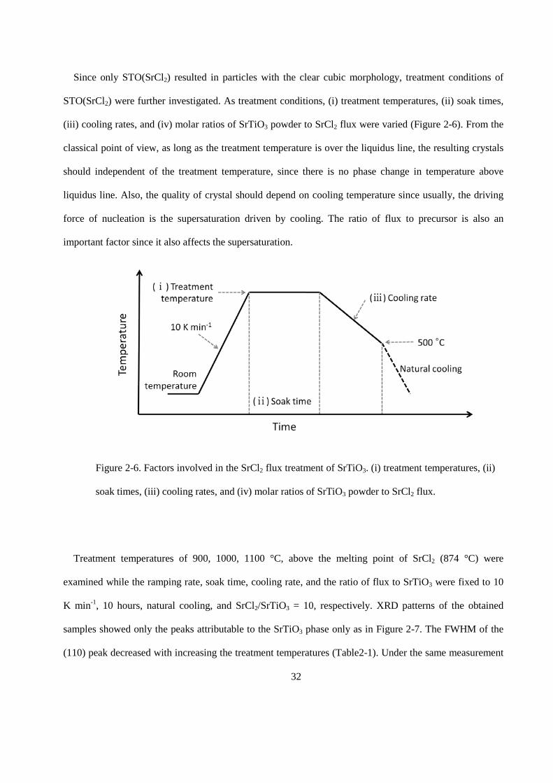
Since only STO(SrCl2) resulted in particles with the clear cubic morphology, treatment conditions of
STO(SrCl2) were further investigated. As treatment conditions, (i) treatment temperatures, (ii) soak times,
(iii) cooling rates, and (iv) molar ratios of SrTiO3 powder to SrCl2 flux were varied (Figure 2-6). From the
classical point of view, as long as the treatment temperature is over the liquidus line, the resulting crystals
should independent of the treatment temperature, since there is no phase change in temperature above
liquidus line. Also, the quality of crystal should depend on cooling temperature since usually, the driving
force of nucleation is the supersaturation driven by cooling. The ratio of flux to precursor is also an
important factor since it also affects the supersaturation.
Treatment temperatures of 900, 1000, 1100 °C, above the melting point of SrCl2 (874 °C) were
examined while the ramping rate, soak time, cooling rate, and the ratio of flux to SrTiO3 were fixed to 10
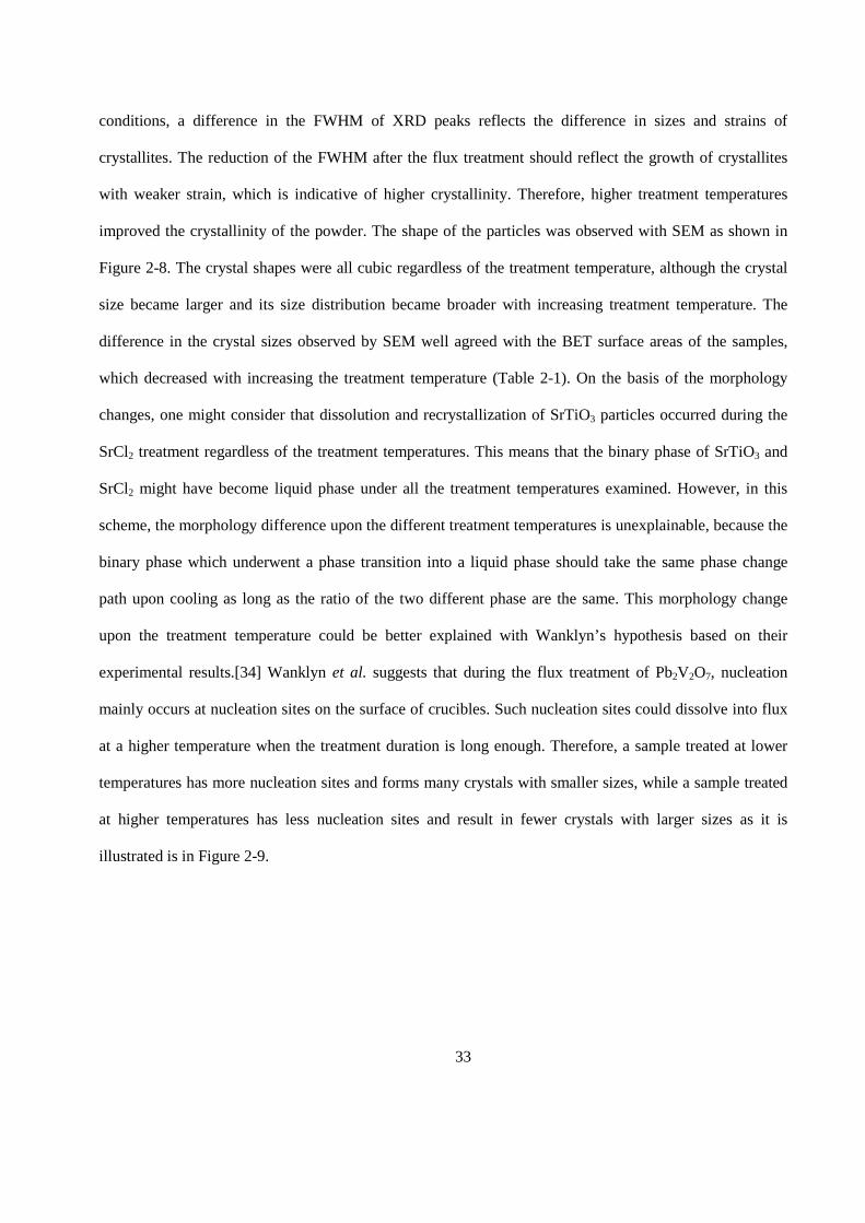
K min-1, 10 hours, natural cooling, and SrCl2/SrTiO3 = 10, respectively. XRD patterns of the obtained
samples showed only the peaks attributable to the SrTiO3 phase only as in Figure 2-7. The FWHM of the
(110) peak decreased with increasing the treatment temperatures (Table2-1). Under the same measurement
Figure 2-6. Factors involved in the SrCl2 flux treatment of SrTiO3. (i) treatment temperatures, (ii)
soak times, (iii) cooling rates, and (iv) molar ratios of SrTiO3 powder to SrCl2 flux.
33
conditions, a difference in the FWHM of XRD peaks reflects the difference in sizes and strains of
crystallites. The reduction of the FWHM after the flux treatment should reflect the growth of crystallites
with weaker strain, which is indicative of higher crystallinity. Therefore, higher treatment temperatures
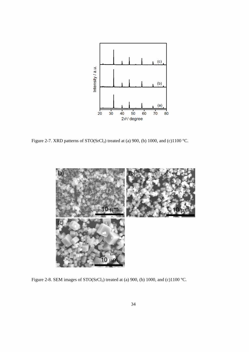
improved the crystallinity of the powder. The shape of the particles was observed with SEM as shown in
Figure 2-8. The crystal shapes were all cubic regardless of the treatment temperature, although the crystal
size became larger and its size distribution became broader with increasing treatment temperature. The
difference in the crystal sizes observed by SEM well agreed with the BET surface areas of the samples,
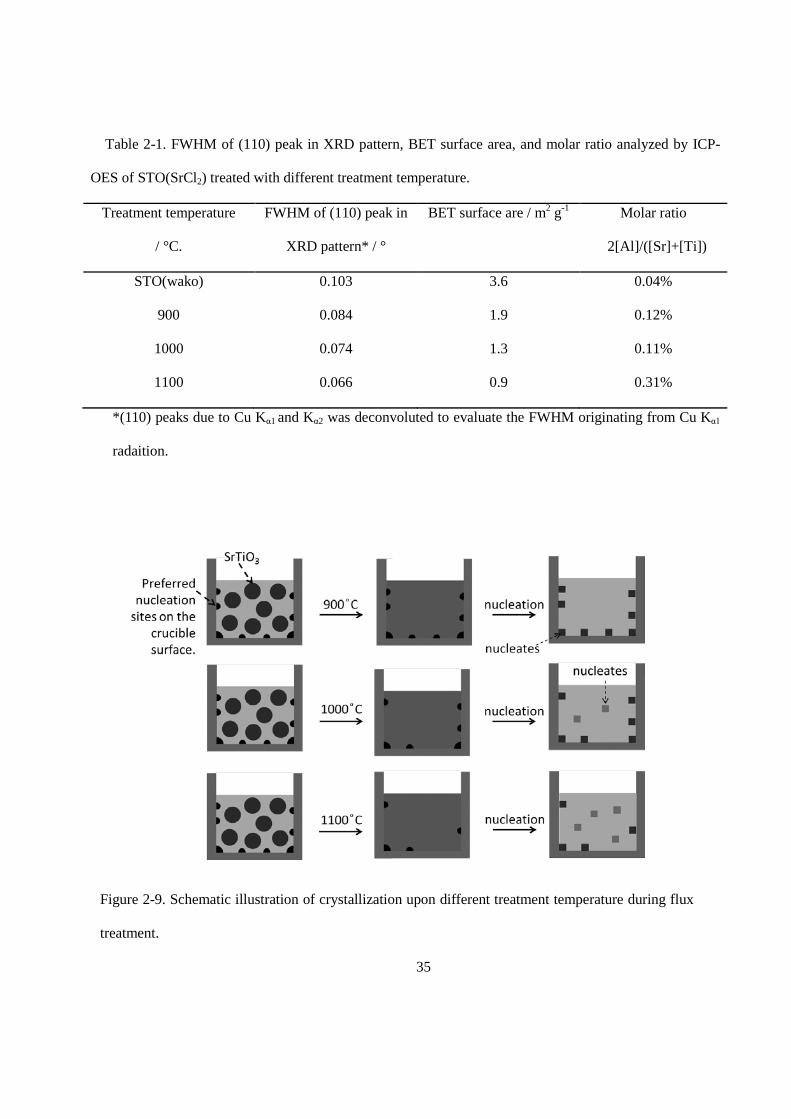
which decreased with increasing the treatment temperature (Table 2-1). On the basis of the morphology
changes, one might consider that dissolution and recrystallization of SrTiO3 particles occurred during the
SrCl2 treatment regardless of the treatment temperatures. This means that the binary phase of SrTiO3 and
SrCl2 might have become liquid phase under all the treatment temperatures examined. However, in this
scheme, the morphology difference upon the different treatment temperatures is unexplainable, because the
binary phase which underwent a phase transition into a liquid phase should take the same phase change
path upon cooling as long as the ratio of the two different phase are the same. This morphology change
upon the treatment temperature could be better explained with Wanklyn’s hypothesis based on their
experimental results.[34] Wanklyn et al. suggests that during the flux treatment of Pb2V2O7, nucleation
mainly occurs at nucleation sites on the surface of crucibles. Such nucleation sites could dissolve into flux
at a higher temperature when the treatment duration is long enough. Therefore, a sample treated at lower
temperatures has more nucleation sites and forms many crystals with smaller sizes, while a sample treated
at higher temperatures has less nucleation sites and result in fewer crystals with larger sizes as it is
illustrated is in Figure 2-9.
34
Figure 2-7. XRD patterns of STO(SrCl2) treated at (a) 900, (b) 1000, and (c)1100 °C.
Figure 2-8. SEM images of STO(SrCl2) treated at (a) 900, (b) 1000, and (c)1100 °C.
35
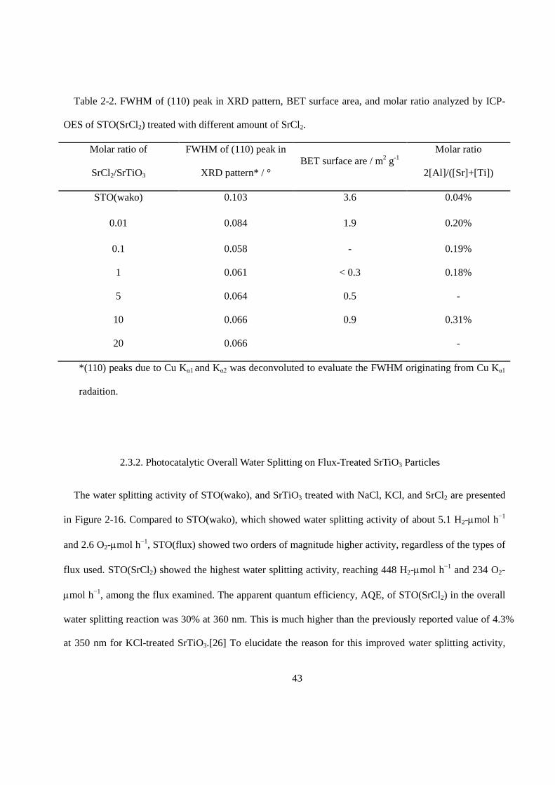
Table 2-1. FWHM of (110) peak in XRD pattern, BET surface area, and molar ratio analyzed by ICP-
OES of STO(SrCl2) treated with different treatment temperature.
Treatment temperature
/ °C.
FWHM of (110) peak in
XRD pattern* / °
BET surface are / m2 g-1 Molar ratio
2[Al]/([Sr]+[Ti])
STO(wako) 0.103 3.6 0.04%
900 0.084 1.9 0.12%
1000 0.074 1.3 0.11%
1100 0.066 0.9 0.31%
*(110) peaks due to Cu Kα1 and Kα2 was deconvoluted to evaluate the FWHM originating from Cu Kα1
radaition.
Figure 2-9. Schematic illustration of crystallization upon different treatment temperature during flux
treatment.
36
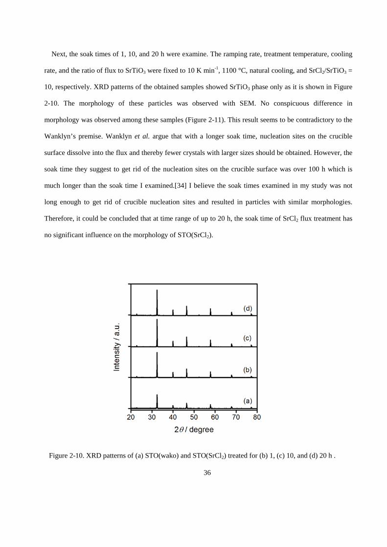
Next, the soak times of 1, 10, and 20 h were examine. The ramping rate, treatment temperature, cooling
rate, and the ratio of flux to SrTiO3 were fixed to 10 K min-1, 1100 °C, natural cooling, and SrCl2/SrTiO3 =
10, respectively. XRD patterns of the obtained samples showed SrTiO3 phase only as it is shown in Figure
2-10. The morphology of these particles was observed with SEM. No conspicuous difference in
morphology was observed among these samples (Figure 2-11). This result seems to be contradictory to the
Wanklyn’s premise. Wanklyn et al. argue that with a longer soak time, nucleation sites on the crucible
surface dissolve into the flux and thereby fewer crystals with larger sizes should be obtained. However, the
soak time they suggest to get rid of the nucleation sites on the crucible surface was over 100 h which is
much longer than the soak time I examined.[34] I believe the soak times examined in my study was not
long enough to get rid of crucible nucleation sites and resulted in particles with similar morphologies.
Therefore, it could be concluded that at time range of up to 20 h, the soak time of SrCl2 flux treatment has
no significant influence on the morphology of STO(SrCl2).
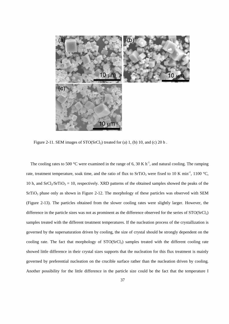
Figure 2-10. XRD patterns of (a) STO(wako) and STO(SrCl2) treated for (b) 1, (c) 10, and (d) 20 h .
37
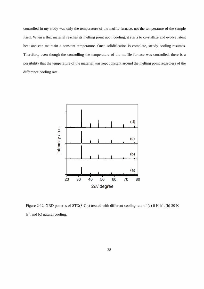
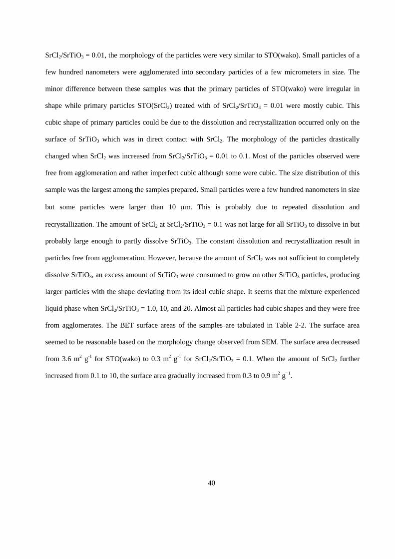
The cooling rates to 500 °C were examined in the range of 6, 30 K h-1, and natural cooling. The ramping
rate, treatment temperature, soak time, and the ratio of flux to SrTiO3 were fixed to 10 K min-1, 1100 °C,
10 h, and SrCl2/SrTiO3 = 10, respectively. XRD patterns of the obtained samples showed the peaks of the
SrTiO3 phase only as shown in Figure 2-12. The morphology of these particles was observed with SEM
(Figure 2-13). The particles obtained from the slower cooling rates were slightly larger. However, the
difference in the particle sizes was not as prominent as the difference observed for the series of STO(SrCl2)
samples treated with the different treatment temperatures. If the nucleation process of the crystallization is
governed by the supersaturation driven by cooling, the size of crystal should be strongly dependent on the
cooling rate. The fact that morphology of STO(SrCl2) samples treated with the different cooling rate
showed little difference in their crystal sizes supports that the nucleation for this flux treatment is mainly
governed by preferential nucleation on the crucible surface rather than the nucleation driven by cooling.
Another possibility for the little difference in the particle size could be the fact that the temperature I
Figure 2-11. SEM images of STO(SrCl2) treated for (a) 1, (b) 10, and (c) 20 h .
38
controlled in my study was only the temperature of the muffle furnace, not the temperature of the sample
itself. When a flux material reaches its melting point upon cooling, it starts to crystallize and evolve latent
heat and can maintain a constant temperature. Once solidification is complete, steady cooling resumes.
Therefore, even though the controlling the temperature of the muffle furnace was controlled, there is a
possibility that the temperature of the material was kept constant around the melting point regardless of the
difference cooling rate.
Figure 2-12. XRD patterns of STO(SrCl2) treated with different cooling rate of (a) 6 K h-1, (b) 30 K
h-1, and (c) natural cooling.
39
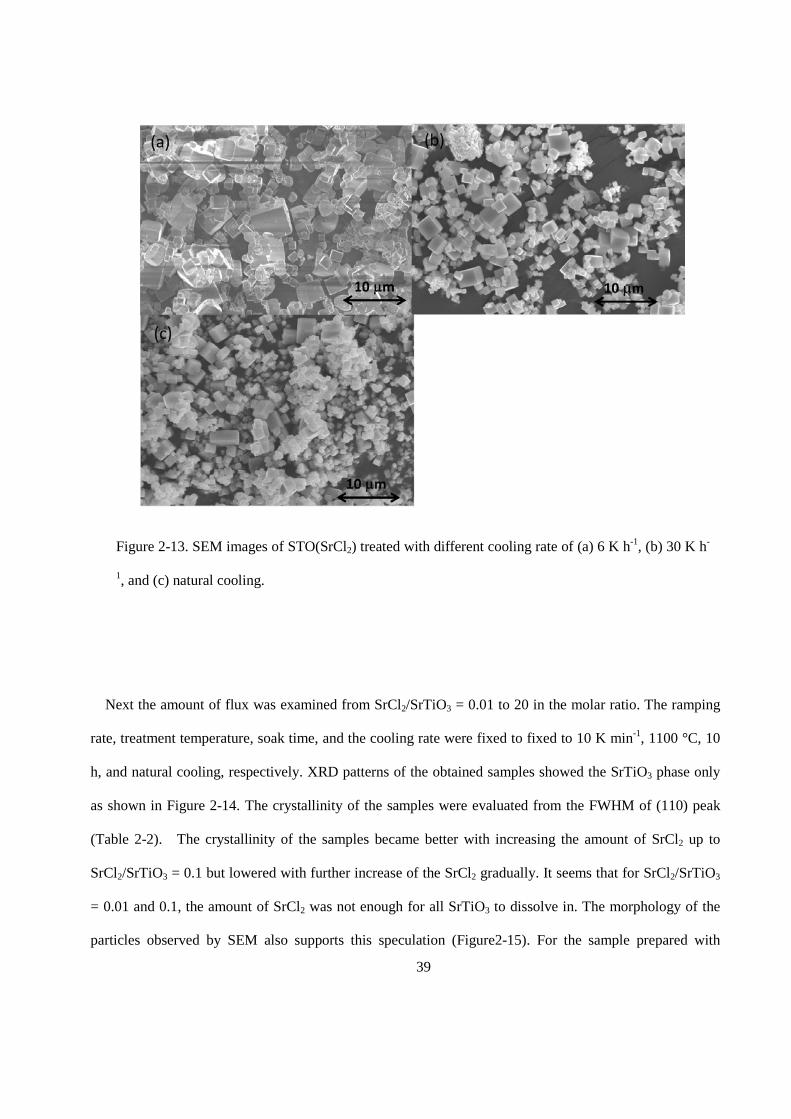
Next the amount of flux was examined from SrCl2/SrTiO3 = 0.01 to 20 in the molar ratio. The ramping
rate, treatment temperature, soak time, and the cooling rate were fixed to fixed to 10 K min-1, 1100 °C, 10
h, and natural cooling, respectively. XRD patterns of the obtained samples showed the SrTiO3 phase only
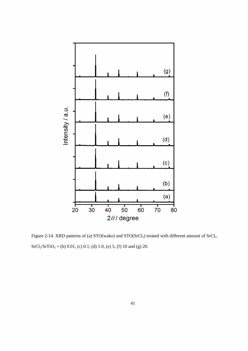
as shown in Figure 2-14. The crystallinity of the samples were evaluated from the FWHM of (110) peak
(Table 2-2). The crystallinity of the samples became better with increasing the amount of SrCl2 up to
SrCl2/SrTiO3 = 0.1 but lowered with further increase of the SrCl2 gradually. It seems that for SrCl2/SrTiO3
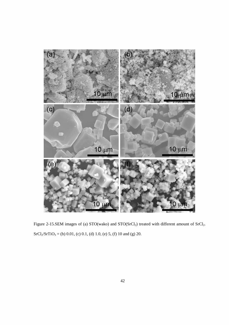
= 0.01 and 0.1, the amount of SrCl2 was not enough for all SrTiO3 to dissolve in. The morphology of the
particles observed by SEM also supports this speculation (Figure2-15). For the sample prepared with
Figure 2-13. SEM images of STO(SrCl2) treated with different cooling rate of (a) 6 K h-1, (b) 30 K h-
1, and (c) natural cooling.
40
SrCl2/SrTiO3 = 0.01, the morphology of the particles were very similar to STO(wako). Small particles of a
few hundred nanometers were agglomerated into secondary particles of a few micrometers in size. The
minor difference between these samples was that the primary particles of STO(wako) were irregular in
shape while primary particles STO(SrCl2) treated with of SrCl2/SrTiO3 = 0.01 were mostly cubic. This
cubic shape of primary particles could be due to the dissolution and recrystallization occurred only on the
surface of SrTiO3 which was in direct contact with SrCl2. The morphology of the particles drastically
changed when SrCl2 was increased from SrCl2/SrTiO3 = 0.01 to 0.1. Most of the particles observed were
free from agglomeration and rather imperfect cubic although some were cubic. The size distribution of this
sample was the largest among the samples prepared. Small particles were a few hundred nanometers in size
but some particles were larger than 10 µm. This is probably due to repeated dissolution and
recrystallization. The amount of SrCl2 at SrCl2/SrTiO3 = 0.1 was not large for all SrTiO3 to dissolve in but
probably large enough to partly dissolve SrTiO3. The constant dissolution and recrystallization result in
particles free from agglomeration. However, because the amount of SrCl2 was not sufficient to completely
dissolve SrTiO3, an excess amount of SrTiO3 were consumed to grow on other SrTiO3 particles, producing
larger particles with the shape deviating from its ideal cubic shape. It seems that the mixture experienced
liquid phase when SrCl2/SrTiO3 = 1.0, 10, and 20. Almost all particles had cubic shapes and they were free
from agglomerates. The BET surface areas of the samples are tabulated in Table 2-2. The surface area
seemed to be reasonable based on the morphology change observed from SEM. The surface area decreased
from 3.6 m2 g-1 for STO(wako) to 0.3 m2 g-1 for SrCl2/SrTiO3 = 0.1. When the amount of SrCl2 further
increased from 0.1 to 10, the surface area gradually increased from 0.3 to 0.9 m2 g−1.
41
Figure 2-14. XRD patterns of (a) STO(wako) and STO(SrCl2) treated with different amount of SrCl2.
SrCl2/SrTiO3 = (b) 0.01, (c) 0.1, (d) 1.0, (e) 5, (f) 10 and (g) 20.
42
Figure 2-15.SEM images of (a) STO(wako) and STO(SrCl2) treated with different amount of SrCl2.
SrCl2/SrTiO3 = (b) 0.01, (c) 0.1, (d) 1.0, (e) 5, (f) 10 and (g) 20.
43
Table 2-2. FWHM of (110) peak in XRD pattern, BET surface area, and molar ratio analyzed by ICP-
OES of STO(SrCl2) treated with different amount of SrCl2.
Molar ratio of
SrCl2/SrTiO3
FWHM of (110) peak in
XRD pattern* / ° BET surface are / m2 g-1
Molar ratio
2[Al]/([Sr]+[Ti])
STO(wako) 0.103 3.6 0.04%
0.01 0.084 1.9 0.20%
0.1 0.058 - 0.19%
1 0.061 < 0.3 0.18%
5 0.064 0.5 -
10 0.066 0.9 0.31%
20 0.066 -
*(110) peaks due to Cu Kα1 and Kα2 was deconvoluted to evaluate the FWHM originating from Cu Kα1
radaition.
2.3.2. Photocatalytic Overall Water Splitting on Flux-Treated SrTiO3 Particles
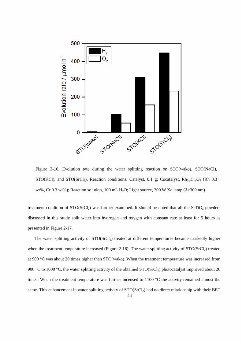
The water splitting activity of STO(wako), and SrTiO3 treated with NaCl, KCl, and SrCl2 are presented
in Figure 2-16. Compared to STO(wako), which showed water splitting activity of about 5.1 H2-µmol h−1
and 2.6 O2-µmol h−1, STO(flux) showed two orders of magnitude higher activity, regardless of the types of
flux used. STO(SrCl2) showed the highest water splitting activity, reaching 448 H2-µmol h−1 and 234 O2-
µmol h−1, among the flux examined. The apparent quantum efficiency, AQE, of STO(SrCl2) in the overall
water splitting reaction was 30% at 360 nm. This is much higher than the previously reported value of 4.3%
at 350 nm for KCl-treated SrTiO3.[26] To elucidate the reason for this improved water splitting activity,
44
treatment condition of STO(SrCl2) was further examined. It should be noted that all the SrTiO3 powders
discussed in this study split water into hydrogen and oxygen with constant rate at least for 5 hours as
presented in Figure 2-17.
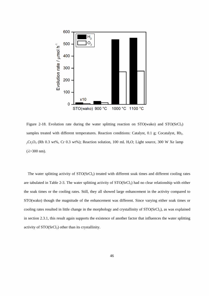
The water splitting activity of STO(SrCl2) treated at different temperatures became markedly higher
when the treatment temperature increased (Figure 2-18). The water splitting activity of STO(SrCl2) treated
at 900 °C was about 20 times higher than STO(wako). When the treatment temperature was increased from
900 °C to 1000 °C, the water splitting activity of the obtained STO(SrCl2) photocatalyst improved about 20
times. When the treatment temperature was further incensed to 1100 °C the activity remained almost the
same. This enhancement in water splitting activity of STO(SrCl2) had no direct relationship with their BET
Figure 2-16. Evolution rate during the water splitting reaction on STO(wako), STO(NaCl),
STO(KCl), and STO(SrCl2). Reaction conditions: Catalyst, 0.1 g; Cocatalyst, Rh2-yCryO3 (Rh 0.3
wt%, Cr 0.3 wt%); Reaction solution, 100 mL H2O; Light source, 300 W Xe lamp (λ>300 nm).
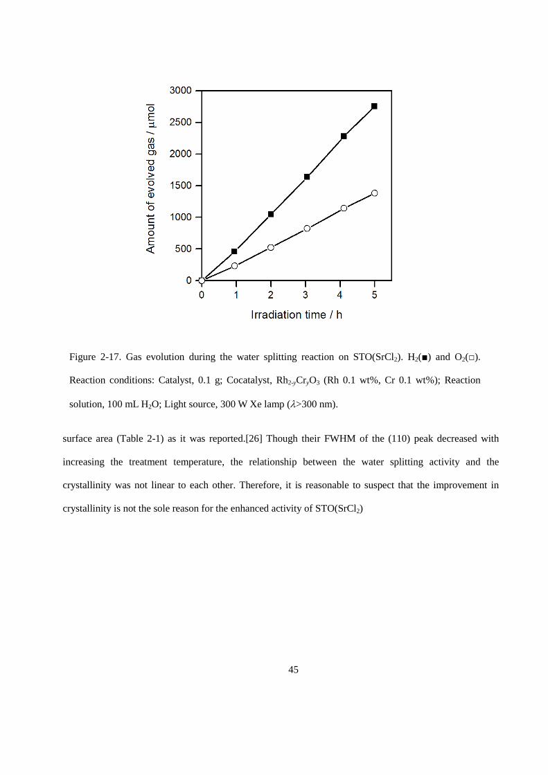
45
surface area (Table 2-1) as it was reported.[26] Though their FWHM of the (110) peak decreased with
increasing the treatment temperature, the relationship between the water splitting activity and the
crystallinity was not linear to each other. Therefore, it is reasonable to suspect that the improvement in
crystallinity is not the sole reason for the enhanced activity of STO(SrCl2)
Figure 2-17. Gas evolution during the water splitting reaction on STO(SrCl2). H2(■) and O2(□).
Reaction conditions: Catalyst, 0.1 g; Cocatalyst, Rh2-yCryO3 (Rh 0.1 wt%, Cr 0.1 wt%); Reaction
solution, 100 mL H2O; Light source, 300 W Xe lamp (λ>300 nm).
46
The water splitting activity of STO(SrCl2) treated with different soak times and different cooling rates
are tabulated in Table 2-3. The water splitting activity of STO(SrCl2) had no clear relationship with either
the soak times or the cooling rates. Still, they all showed large enhancement in the activity compared to
STO(wako) though the magnitude of the enhancement was different. Since varying either soak times or
cooling rates resulted in little change in the morphology and crystallinity of STO(SrCl2), as was explained
in section 2.3.1, this result again supports the existence of another factor that influences the water splitting
activity of STO(SrCl2) other than its crystallinity.
Figure 2-18. Evolution rate during the water splitting reaction on STO(wako) and STO(SrCl2)
samples treated with different temperatures. Reaction conditions: Catalyst, 0.1 g; Cocatalyst, Rh2-
yCryO3 (Rh 0.3 wt%, Cr 0.3 wt%); Reaction solution, 100 mL H2O; Light source, 300 W Xe lamp
(λ>300 nm).
47
Table 2-3.Gas evolution rate during the water splitting reaction on STO(SrCl2) treated with different
soak times and cooling rates.
Soak time / h Cooling rate Evolution rate / µmol h-1
H2 O2
1 Natural 390 210
10 Natural 440 40
20 Natural 420 220
10 6 380 200
10 30 500 270
Reaction conditions: Catalyst, 0.1 g; Cocatalyst, Rh2-yCryO3 (Rh 0.3 wt%, Cr 0.3 wt%); Reaction
solution, 100 mL H2O; Light source, 300 W Xe lamp (λ >300 nm).source.
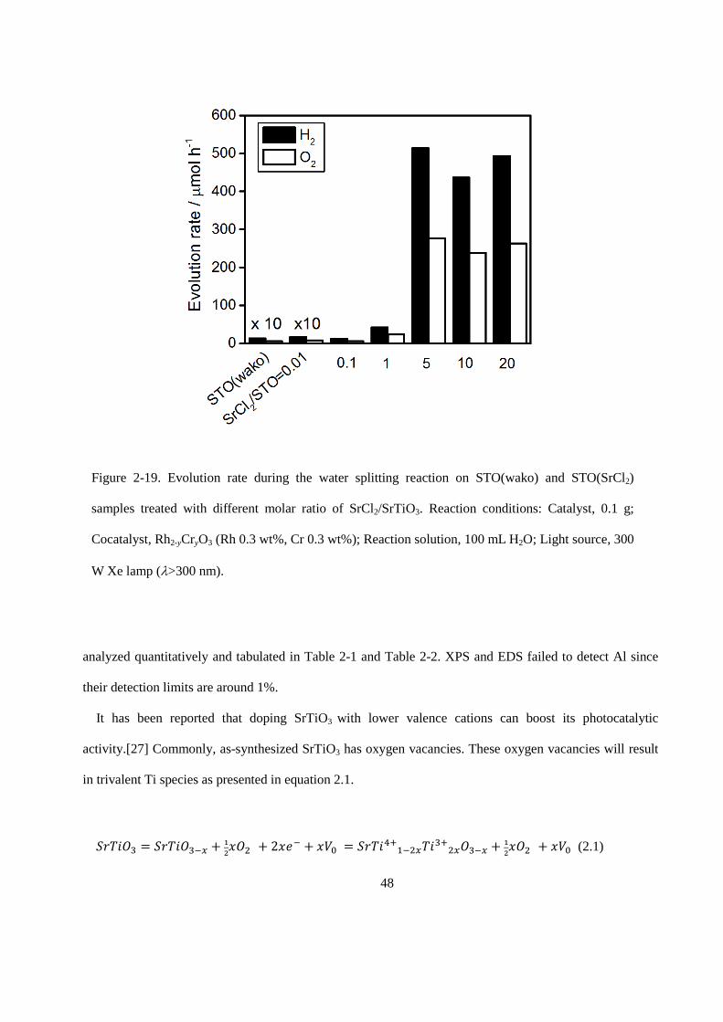
The water splitting activity of STO(SrCl2) treated with different amounts of SrCl2 is shown in Figure 2-
19. The activity of STO(SrCl2) increased with increasing the amounts of SrCl2 up to SrCl2/SrTiO3 = 5 and
reached plateau upon further increase. This enhancement in the water splitting activity of STO(SrCl2) had
no direct relationship with their BET surface areas or with their FWHM of the (110) peak (Table 2-2). The
existence of another factor that influences the water splitting activity of STO(SrCl2) other than the
crystallinity is now quite clear. Since the water splitting activity of STO(SrCl2) increased with increasing
the temperature and with increasing amount of SrCl2 to some extent, incorporation of impurity into
STO(SrCl2) is suspected. No conspicuous impurity peak was observed in STO(SrCl2) treated at 1100 °C
and with SrCl2/SrTiO3 = 10 from XPS or EDS analysis. However, with ICP analysis it was revealed that
very small amounts of Al (< 1%) were indeed incorporated into STO(SrCl2). It seems that Al impurity was
derived from the alumina crucibles during the flux treatment. The amount of Al detected by ICP-OES was
48
analyzed quantitatively and tabulated in Table 2-1 and Table 2-2. XPS and EDS failed to detect Al since
their detection limits are around 1%.
It has been reported that doping SrTiO3 with lower valence cations can boost its photocatalytic
activity.[27] Commonly, as-synthesized SrTiO3 has oxygen vacancies. These oxygen vacancies will result
in trivalent Ti species as presented in equation 2.1.
𝑆𝑆𝑆𝑆𝑆𝑆𝑆𝑆𝑂𝑂3 = 𝑆𝑆𝑆𝑆𝑆𝑆𝑆𝑆𝑂𝑂3−𝑓𝑓 + 12𝑥𝑥𝑂𝑂2 + 2𝑥𝑥𝑒𝑒− + 𝑥𝑥𝑉𝑉0 = 𝑆𝑆𝑆𝑆𝑆𝑆𝑆𝑆4+1−2𝑓𝑓𝑆𝑆𝑆𝑆3+2𝑓𝑓𝑂𝑂3−𝑓𝑓 + 1
2𝑥𝑥𝑂𝑂2 + 𝑥𝑥𝑉𝑉0 (2.1)
Figure 2-19. Evolution rate during the water splitting reaction on STO(wako) and STO(SrCl2)
samples treated with different molar ratio of SrCl2/SrTiO3. Reaction conditions: Catalyst, 0.1 g;
Cocatalyst, Rh2-yCryO3 (Rh 0.3 wt%, Cr 0.3 wt%); Reaction solution, 100 mL H2O; Light source, 300
W Xe lamp (λ>300 nm).
49
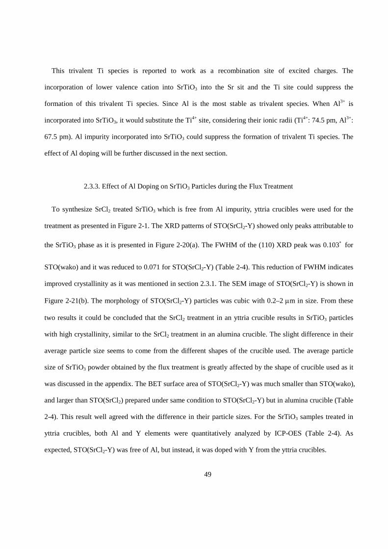
This trivalent Ti species is reported to work as a recombination site of excited charges. The
incorporation of lower valence cation into SrTiO3 into the Sr sit and the Ti site could suppress the
formation of this trivalent Ti species. Since Al is the most stable as trivalent species. When Al3+ is
incorporated into SrTiO3, it would substitute the Ti4+ site, considering their ionic radii (Ti4+: 74.5 pm, Al3+:
67.5 pm). Al impurity incorporated into SrTiO3 could suppress the formation of trivalent Ti species. The
effect of Al doping will be further discussed in the next section.
2.3.3. Effect of Al Doping on SrTiO3 Particles during the Flux Treatment
To synthesize SrCl2 treated SrTiO3 which is free from Al impurity, yttria crucibles were used for the
treatment as presented in Figure 2-1. The XRD patterns of STO(SrCl2-Y) showed only peaks attributable to
the SrTiO3 phase as it is presented in Figure 2-20(a). The FWHM of the (110) XRD peak was 0.103˚ for
STO(wako) and it was reduced to 0.071 for STO(SrCl2-Y) (Table 2-4). This reduction of FWHM indicates
improved crystallinity as it was mentioned in section 2.3.1. The SEM image of STO(SrCl2-Y) is shown in
Figure 2-21(b). The morphology of STO(SrCl2-Y) particles was cubic with 0.2–2 µm in size. From these
two results it could be concluded that the SrCl2 treatment in an yttria crucible results in SrTiO3 particles
with high crystallinity, similar to the SrCl2 treatment in an alumina crucible. The slight difference in their
average particle size seems to come from the different shapes of the crucible used. The average particle
size of SrTiO3 powder obtained by the flux treatment is greatly affected by the shape of crucible used as it
was discussed in the appendix. The BET surface area of STO(SrCl2-Y) was much smaller than STO(wako),
and larger than STO(SrCl2) prepared under same condition to STO(SrCl2-Y) but in alumina crucible (Table
2-4). This result well agreed with the difference in their particle sizes. For the SrTiO3 samples treated in
yttria crucibles, both Al and Y elements were quantitatively analyzed by ICP-OES (Table 2-4). As
expected, STO(SrCl2-Y) was free of Al, but instead, it was doped with Y from the yttria crucibles.
50
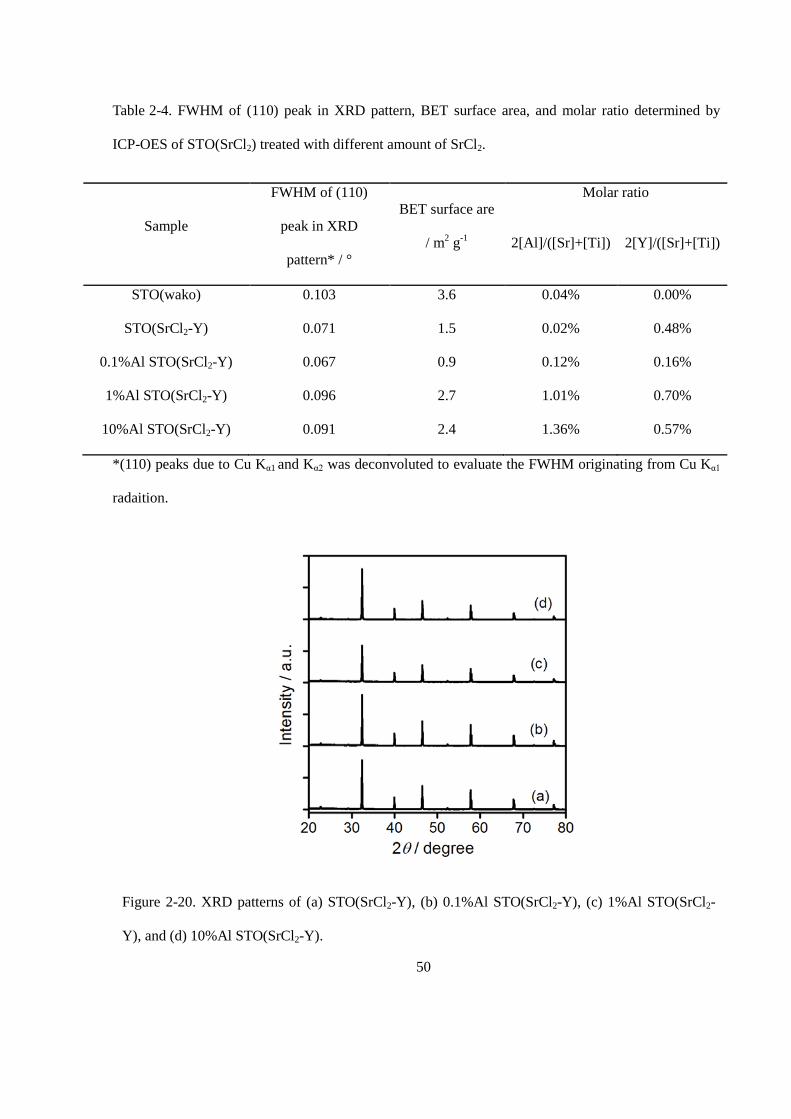
Table 2-4. FWHM of (110) peak in XRD pattern, BET surface area, and molar ratio determined by
ICP-OES of STO(SrCl2) treated with different amount of SrCl2.
Sample
FWHM of (110)
peak in XRD
pattern* / °
BET surface are
/ m2 g-1
Molar ratio
2[Al]/([Sr]+[Ti]) 2[Y]/([Sr]+[Ti])
STO(wako) 0.103 3.6 0.04% 0.00%
STO(SrCl2-Y) 0.071 1.5 0.02% 0.48%
0.1%Al STO(SrCl2-Y) 0.067 0.9 0.12% 0.16%
1%Al STO(SrCl2-Y) 0.096 2.7 1.01% 0.70%
10%Al STO(SrCl2-Y) 0.091 2.4 1.36% 0.57%
*(110) peaks due to Cu Kα1 and Kα2 was deconvoluted to evaluate the FWHM originating from Cu Kα1
radaition.
Figure 2-20. XRD patterns of (a) STO(SrCl2-Y), (b) 0.1%Al STO(SrCl2-Y), (c) 1%Al STO(SrCl2-
Y), and (d) 10%Al STO(SrCl2-Y).
51
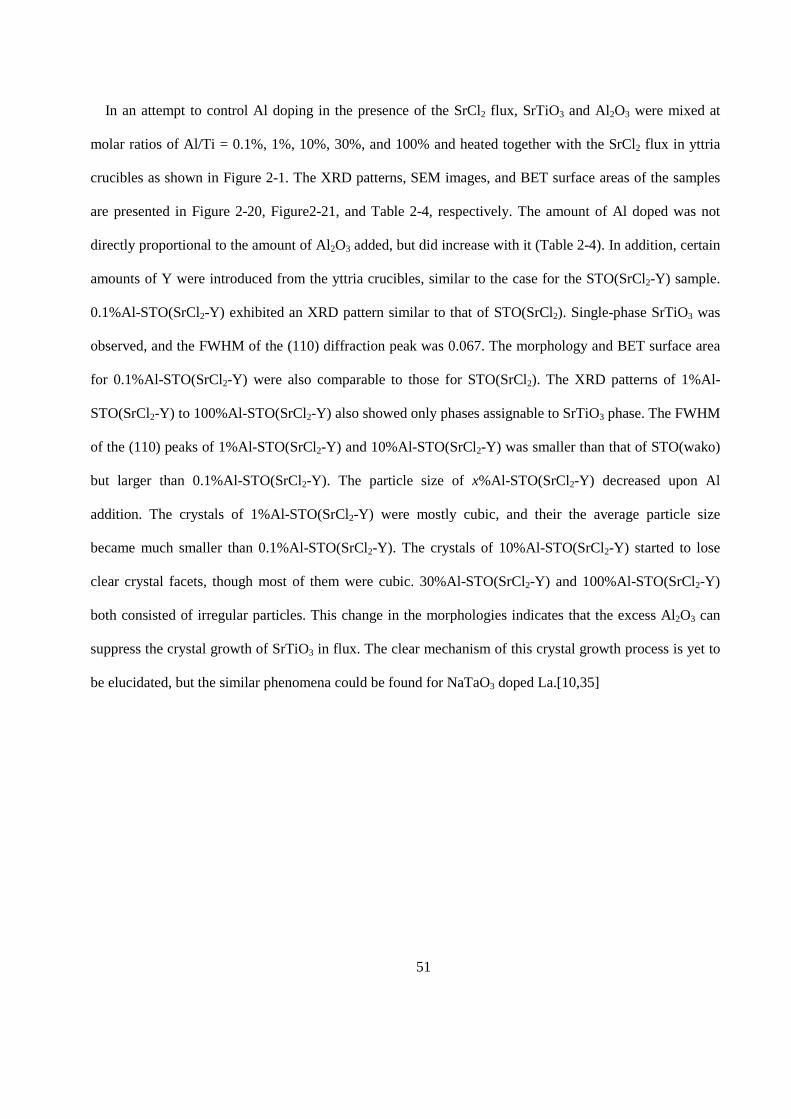
In an attempt to control Al doping in the presence of the SrCl2 flux, SrTiO3 and Al2O3 were mixed at
molar ratios of Al/Ti = 0.1%, 1%, 10%, 30%, and 100% and heated together with the SrCl2 flux in yttria
crucibles as shown in Figure 2-1. The XRD patterns, SEM images, and BET surface areas of the samples
are presented in Figure 2-20, Figure2-21, and Table 2-4, respectively. The amount of Al doped was not
directly proportional to the amount of Al2O3 added, but did increase with it (Table 2-4). In addition, certain
amounts of Y were introduced from the yttria crucibles, similar to the case for the STO(SrCl2-Y) sample.
0.1%Al-STO(SrCl2-Y) exhibited an XRD pattern similar to that of STO(SrCl2). Single-phase SrTiO3 was
observed, and the FWHM of the (110) diffraction peak was 0.067. The morphology and BET surface area
for 0.1%Al-STO(SrCl2-Y) were also comparable to those for STO(SrCl2). The XRD patterns of 1%Al-
STO(SrCl2-Y) to 100%Al-STO(SrCl2-Y) also showed only phases assignable to SrTiO3 phase. The FWHM
of the (110) peaks of 1%Al-STO(SrCl2-Y) and 10%Al-STO(SrCl2-Y) was smaller than that of STO(wako)
but larger than 0.1%Al-STO(SrCl2-Y). The particle size of x%Al-STO(SrCl2-Y) decreased upon Al
addition. The crystals of 1%Al-STO(SrCl2-Y) were mostly cubic, and their the average particle size
became much smaller than 0.1%Al-STO(SrCl2-Y). The crystals of 10%Al-STO(SrCl2-Y) started to lose
clear crystal facets, though most of them were cubic. 30%Al-STO(SrCl2-Y) and 100%Al-STO(SrCl2-Y)
both consisted of irregular particles. This change in the morphologies indicates that the excess Al2O3 can
suppress the crystal growth of SrTiO3 in flux. The clear mechanism of this crystal growth process is yet to
be elucidated, but the similar phenomena could be found for NaTaO3 doped La.[10,35]
52
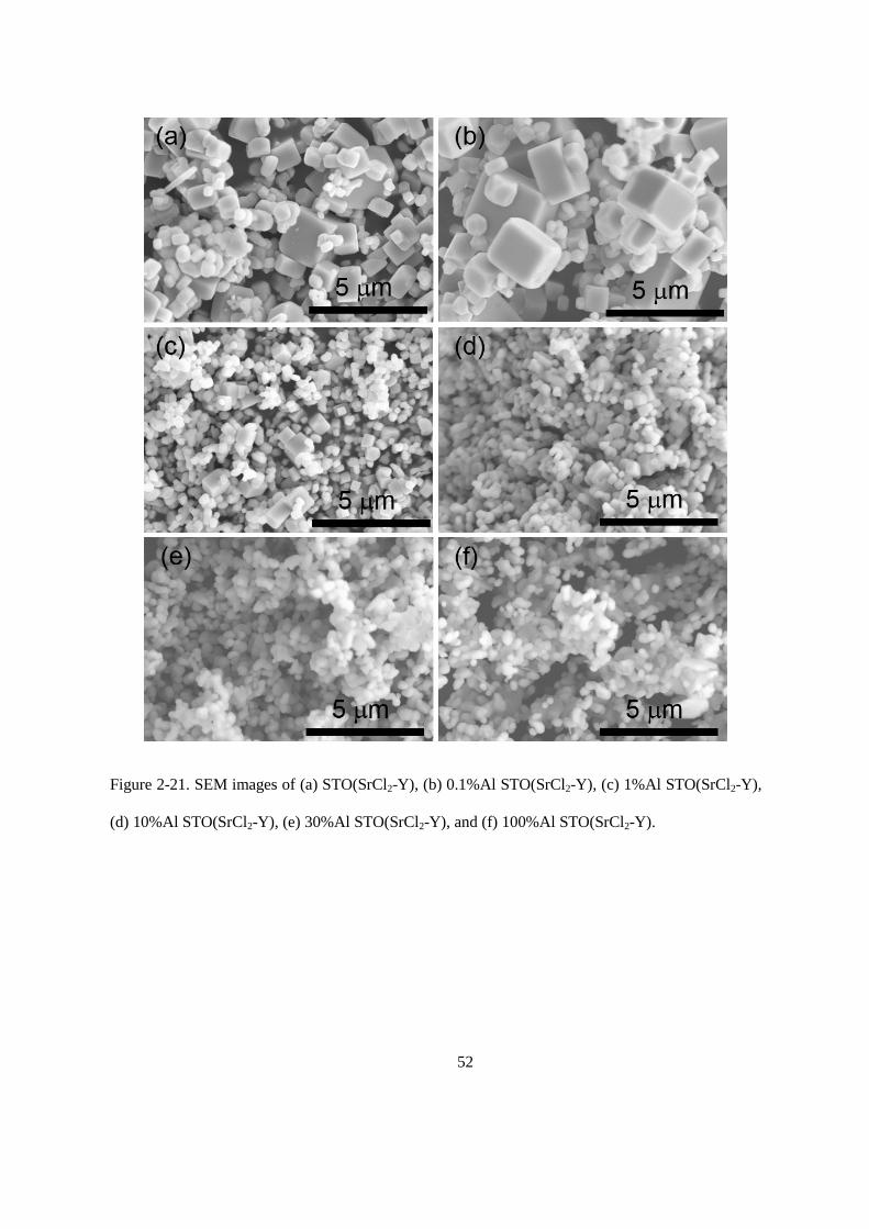
Figure 2-21. SEM images of (a) STO(SrCl2-Y), (b) 0.1%Al STO(SrCl2-Y), (c) 1%Al STO(SrCl2-Y),
(d) 10%Al STO(SrCl2-Y), (e) 30%Al STO(SrCl2-Y), and (f) 100%Al STO(SrCl2-Y).
53
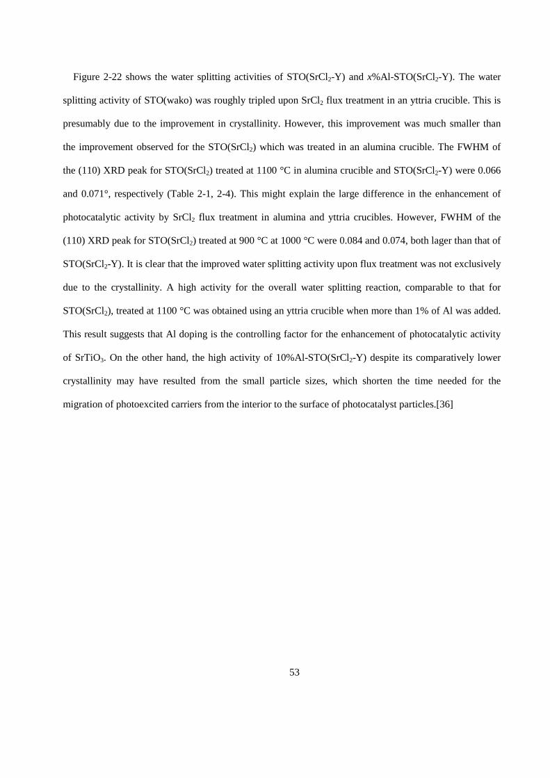
Figure 2-22 shows the water splitting activities of STO(SrCl2-Y) and x%Al-STO(SrCl2-Y). The water
splitting activity of STO(wako) was roughly tripled upon SrCl2 flux treatment in an yttria crucible. This is
presumably due to the improvement in crystallinity. However, this improvement was much smaller than
the improvement observed for the STO(SrCl2) which was treated in an alumina crucible. The FWHM of
the (110) XRD peak for STO(SrCl2) treated at 1100 °C in alumina crucible and STO(SrCl2-Y) were 0.066
and 0.071°, respectively (Table 2-1, 2-4). This might explain the large difference in the enhancement of
photocatalytic activity by SrCl2 flux treatment in alumina and yttria crucibles. However, FWHM of the
(110) XRD peak for STO(SrCl2) treated at 900 °C at 1000 °C were 0.084 and 0.074, both lager than that of
STO(SrCl2-Y). It is clear that the improved water splitting activity upon flux treatment was not exclusively
due to the crystallinity. A high activity for the overall water splitting reaction, comparable to that for
STO(SrCl2), treated at 1100 °C was obtained using an yttria crucible when more than 1% of Al was added.
This result suggests that Al doping is the controlling factor for the enhancement of photocatalytic activity
of SrTiO3. On the other hand, the high activity of 10%Al-STO(SrCl2-Y) despite its comparatively lower
crystallinity may have resulted from the small particle sizes, which shorten the time needed for the
migration of photoexcited carriers from the interior to the surface of photocatalyst particles.[36]
54
To examine the effect of aluminum doping separately, Al2O3 was added as a dopant to SrTiO3 at Al/Ti
molar ratios ranging from 0.1% to 10%, and the mixtures were calcined in the absence of the SrCl2 flux for
a solid state reaction as shown in Figure 2-1. As tabulated in Table 2-5, the Al content increased
monotonically with increasing amount of Al2O3 addition, although the amounts detected were somehow
lower than the amounts added to the starting material for high Al2O3 contents (Al >5%). At this doping
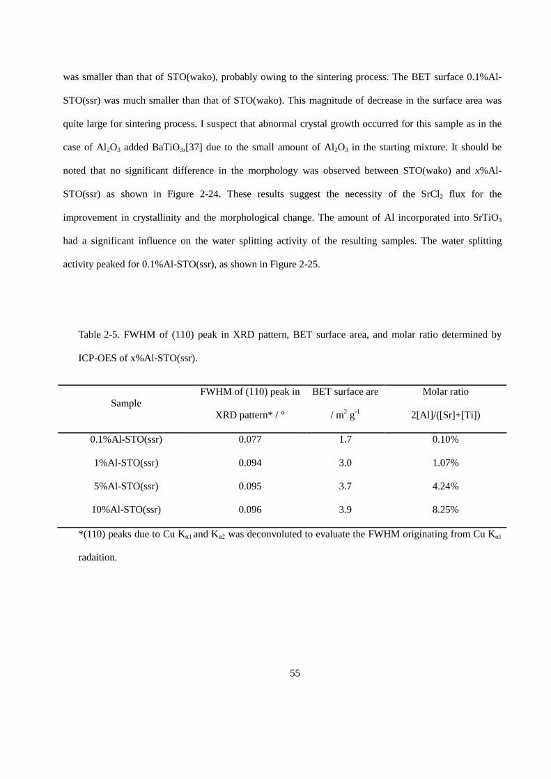
amount, no impurity phase was detected in the XRD patterns of the sample (Figure 2-23). As tabulated in
Table 2-5, the BET surface areas of 5%Al- and 10%Al-STO(ssr) were larger than that of STO(wako),
probably due to the presence of unreacted, amorphous Al2O3. The BET surface area of 1% Al-STO(ssr)
Figure 2-22. Evolution rate during the water splitting reaction on x%Al STO(SrCl2-Y). Reaction
conditions: Catalyst, 0.1 g; Cocatalyst, Rh2-yCryO3 (Rh 0.1 wt%, Cr 0.1 wt%); Reaction solution, 100
mL H2O; Light source, 300 W Xe lamp (λ>300 nm).
55
was smaller than that of STO(wako), probably owing to the sintering process. The BET surface 0.1%Al-
STO(ssr) was much smaller than that of STO(wako). This magnitude of decrease in the surface area was
quite large for sintering process. I suspect that abnormal crystal growth occurred for this sample as in the
case of Al2O3 added BaTiO3,[37] due to the small amount of Al2O3 in the starting mixture. It should be
noted that no significant difference in the morphology was observed between STO(wako) and x%Al-
STO(ssr) as shown in Figure 2-24. These results suggest the necessity of the SrCl2 flux for the
improvement in crystallinity and the morphological change. The amount of Al incorporated into SrTiO3
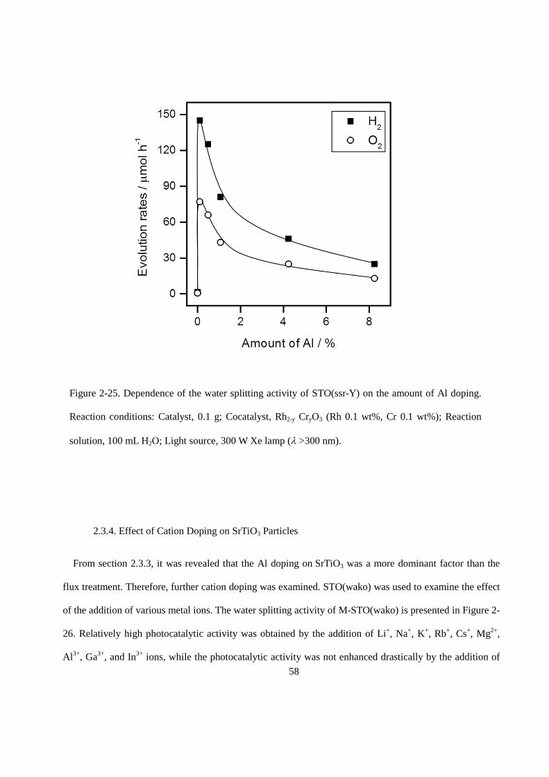
had a significant influence on the water splitting activity of the resulting samples. The water splitting
activity peaked for 0.1%Al-STO(ssr), as shown in Figure 2-25.
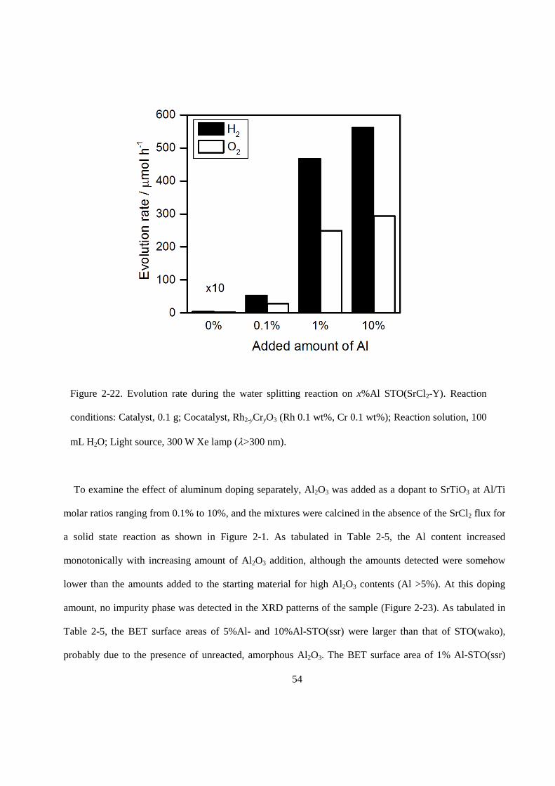
Table 2-5. FWHM of (110) peak in XRD pattern, BET surface area, and molar ratio determined by
ICP-OES of x%Al-STO(ssr).
Sample FWHM of (110) peak in
XRD pattern* / °
BET surface are
/ m2 g-1
Molar ratio
2[Al]/([Sr]+[Ti])
0.1%Al-STO(ssr) 0.077 1.7 0.10%
1%Al-STO(ssr) 0.094 3.0 1.07%
5%Al-STO(ssr) 0.095 3.7 4.24%
10%Al-STO(ssr) 0.096 3.9 8.25%
*(110) peaks due to Cu Kα1 and Kα2 was deconvoluted to evaluate the FWHM originating from Cu Kα1
radaition.
56
It should be noted that Al doping of SrTiO3 was more effective when SrCl2 was present during the
heating. The doping amount of Al in the STO(SrCl2) sample from an alumina crucible may vary depending
on the treatment conditions. Nevertheless, this sample showed a higher photocatalytic activity than the
x%Al-STO(ssr) samples containing various and controlled amounts of Al. It is thought that Al was not
effectively doped into SrTiO3 during the solid state reaction because Al had to diffuse from the outer
surface of the particles. In contrast, a significant portion of the SrTiO3 particles was once dissolved and
recrystallized in the presence of SrCl2 flux, together with alumina derived from the crucibles. During this
process, some of the Al ions may be doped into the middle part of the SrTiO3 particles and occupy the
most stable state thermodynamically. As a result, Al doping can show stronger enhancement of
photocatalytic activity when the SrCl2 flux is used. Thus, it is concluded that the dramatic improvement in
Figure 2-23. XRD patterns of (a) 0.1%Al-, (b) 1%Al-, (c) 5%Al-, and (d) 10%Al-STO(ssr).
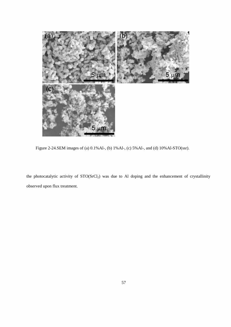
57
the photocatalytic activity of STO(SrCl2) was due to Al doping and the enhancement of crystallinity
observed upon flux treatment.
Figure 2-24.SEM images of (a) 0.1%Al-, (b) 1%Al-, (c) 5%Al-, and (d) 10%Al-STO(ssr).
58
2.3.4. Effect of Cation Doping on SrTiO3 Particles
From section 2.3.3, it was revealed that the Al doping on SrTiO3 was a more dominant factor than the
flux treatment. Therefore, further cation doping was examined. STO(wako) was used to examine the effect
of the addition of various metal ions. The water splitting activity of M-STO(wako) is presented in Figure 2-
26. Relatively high photocatalytic activity was obtained by the addition of Li+, Na+, K+, Rb+, Cs+, Mg2+,
Al3+, Ga3+, and In3+ ions, while the photocatalytic activity was not enhanced drastically by the addition of
Figure 2-25. Dependence of the water splitting activity of STO(ssr-Y) on the amount of Al doping.
Reaction conditions: Catalyst, 0.1 g; Cocatalyst, Rh2-y CryO3 (Rh 0.1 wt%, Cr 0.1 wt%); Reaction
solution, 100 mL H2O; Light source, 300 W Xe lamp (λ >300 nm).
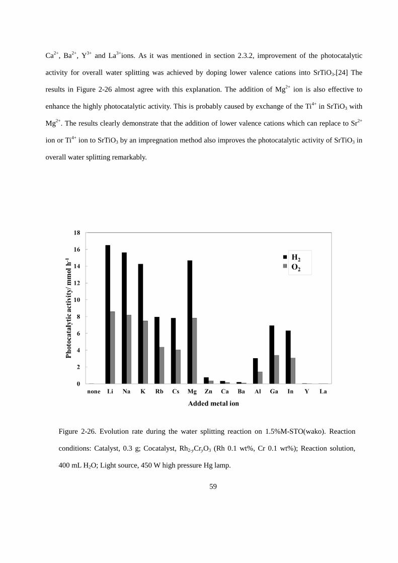
59
Ca2+, Ba2+, Y3+ and La3+ions. As it was mentioned in section 2.3.2, improvement of the photocatalytic
activity for overall water splitting was achieved by doping lower valence cations into SrTiO3.[24] The
results in Figure 2-26 almost agree with this explanation. The addition of Mg2+ ion is also effective to
enhance the highly photocatalytic activity. This is probably caused by exchange of the Ti4+ in SrTiO3 with
Mg2+. The results clearly demonstrate that the addition of lower valence cations which can replace to Sr2+
ion or Ti4+ ion to SrTiO3 by an impregnation method also improves the photocatalytic activity of SrTiO3 in
overall water splitting remarkably.
Figure 2-26. Evolution rate during the water splitting reaction on 1.5%M-STO(wako). Reaction
conditions: Catalyst, 0.3 g; Cocatalyst, Rh2-yCryO3 (Rh 0.1 wt%, Cr 0.1 wt%); Reaction solution,
400 mL H2O; Light source, 450 W high pressure Hg lamp.
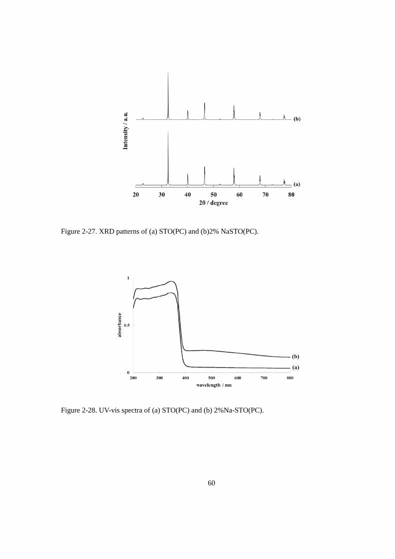
60
Figure 2-27. XRD patterns of (a) STO(PC) and (b)2% NaSTO(PC).
Figure 2-28. UV-vis spectra of (a) STO(PC) and (b) 2%Na-STO(PC).
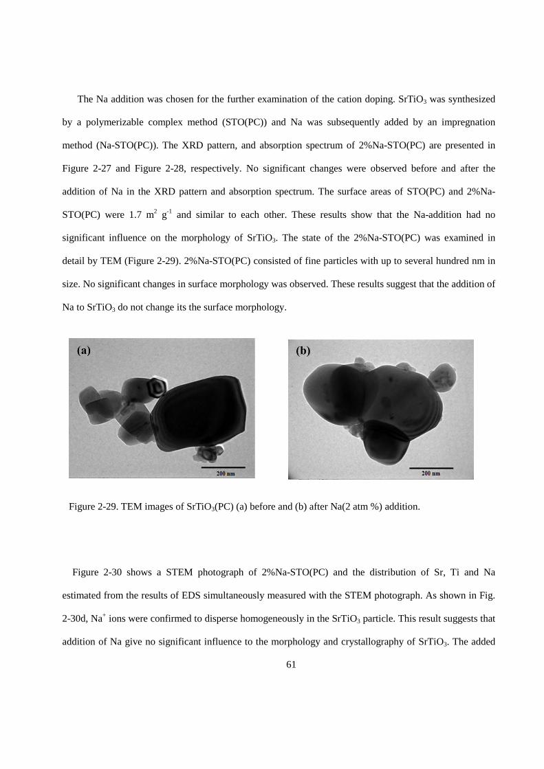
61
The Na addition was chosen for the further examination of the cation doping. SrTiO3 was synthesized
by a polymerizable complex method (STO(PC)) and Na was subsequently added by an impregnation
method (Na-STO(PC)). The XRD pattern, and absorption spectrum of 2%Na-STO(PC) are presented in
Figure 2-27 and Figure 2-28, respectively. No significant changes were observed before and after the
addition of Na in the XRD pattern and absorption spectrum. The surface areas of STO(PC) and 2%Na-
STO(PC) were 1.7 m2 g-1 and similar to each other. These results show that the Na-addition had no
significant influence on the morphology of SrTiO3. The state of the 2%Na-STO(PC) was examined in
detail by TEM (Figure 2-29). 2%Na-STO(PC) consisted of fine particles with up to several hundred nm in
size. No significant changes in surface morphology was observed. These results suggest that the addition of
Na to SrTiO3 do not change its the surface morphology.
Figure 2-30 shows a STEM photograph of 2%Na-STO(PC) and the distribution of Sr, Ti and Na
estimated from the results of EDS simultaneously measured with the STEM photograph. As shown in Fig.
2-30d, Na+ ions were confirmed to disperse homogeneously in the SrTiO3 particle. This result suggests that
addition of Na give no significant influence to the morphology and crystallography of SrTiO3. The added
Figure 2-29. TEM images of SrTiO3(PC) (a) before and (b) after Na(2 atm %) addition.
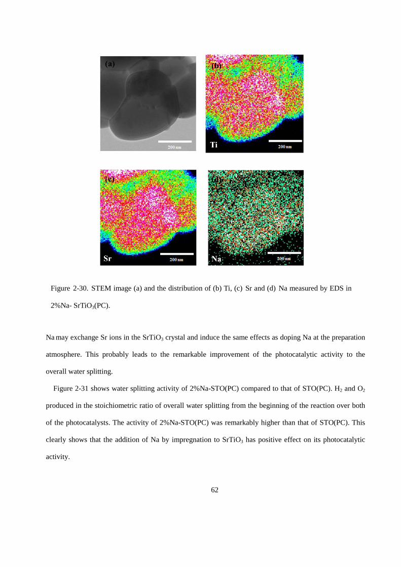
62
Na may exchange Sr ions in the SrTiO3 crystal and induce the same effects as doping Na at the preparation
atmosphere. This probably leads to the remarkable improvement of the photocatalytic activity to the
overall water splitting.
Figure 2-31 shows water splitting activity of 2%Na-STO(PC) compared to that of STO(PC). H2 and O2
produced in the stoichiometric ratio of overall water splitting from the beginning of the reaction over both
of the photocatalysts. The activity of 2%Na-STO(PC) was remarkably higher than that of STO(PC). This
clearly shows that the addition of Na by impregnation to SrTiO3 has positive effect on its photocatalytic
activity.
Figure 2-30. STEM image (a) and the distribution of (b) Ti, (c) Sr and (d) Na measured by EDS in
2%Na- SrTiO3(PC).
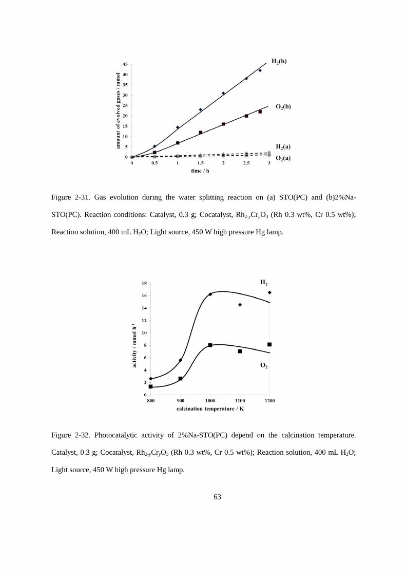
63
Figure 2-31. Gas evolution during the water splitting reaction on (a) STO(PC) and (b)2%Na-
STO(PC). Reaction conditions: Catalyst, 0.3 g; Cocatalyst, Rh2-yCryO3 (Rh 0.3 wt%, Cr 0.5 wt%);
Reaction solution, 400 mL H2O; Light source, 450 W high pressure Hg lamp.
Figure 2-32. Photocatalytic activity of 2%Na-STO(PC) depend on the calcination temperature.
Catalyst, 0.3 g; Cocatalyst, Rh2-yCryO3 (Rh 0.3 wt%, Cr 0.5 wt%); Reaction solution, 400 mL H2O;
Light source, 450 W high pressure Hg lamp.
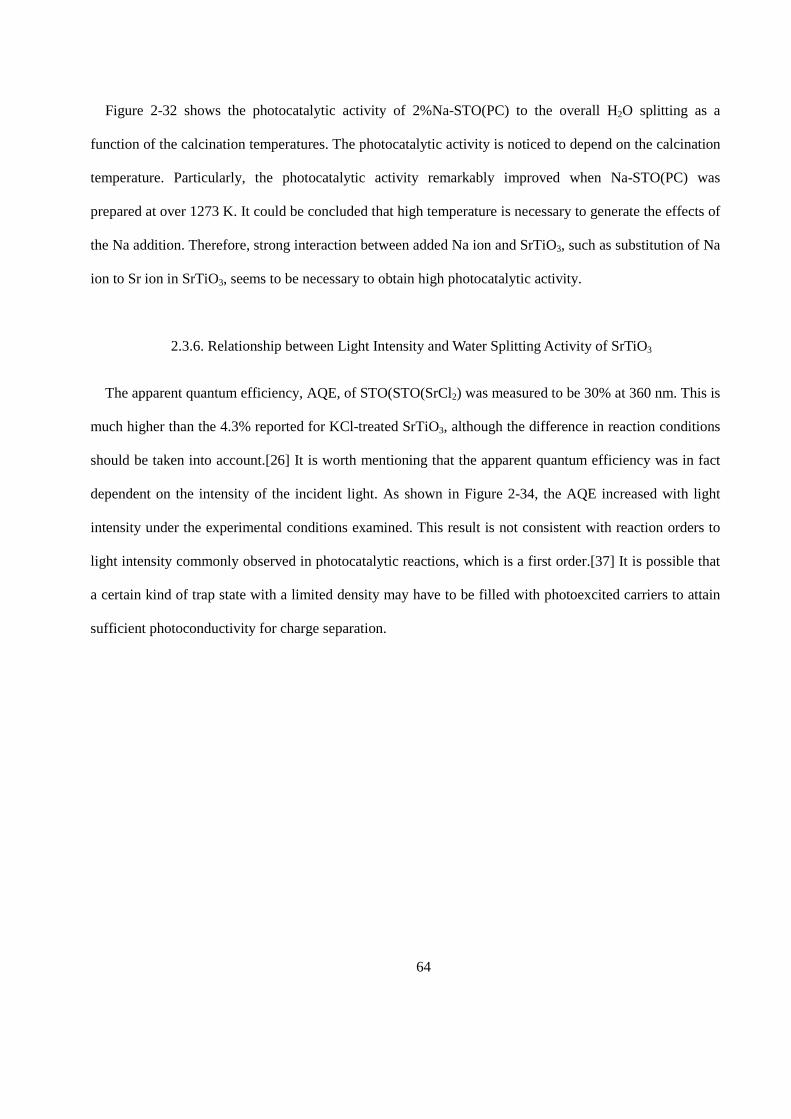
64
Figure 2-32 shows the photocatalytic activity of 2%Na-STO(PC) to the overall H2O splitting as a
function of the calcination temperatures. The photocatalytic activity is noticed to depend on the calcination
temperature. Particularly, the photocatalytic activity remarkably improved when Na-STO(PC) was
prepared at over 1273 K. It could be concluded that high temperature is necessary to generate the effects of
the Na addition. Therefore, strong interaction between added Na ion and SrTiO3, such as substitution of Na
ion to Sr ion in SrTiO3, seems to be necessary to obtain high photocatalytic activity.
2.3.6. Relationship between Light Intensity and Water Splitting Activity of SrTiO3
The apparent quantum efficiency, AQE, of STO(STO(SrCl2) was measured to be 30% at 360 nm. This is
much higher than the 4.3% reported for KCl-treated SrTiO3, although the difference in reaction conditions
should be taken into account.[26] It is worth mentioning that the apparent quantum efficiency was in fact
dependent on the intensity of the incident light. As shown in Figure 2-34, the AQE increased with light
intensity under the experimental conditions examined. This result is not consistent with reaction orders to
light intensity commonly observed in photocatalytic reactions, which is a first order.[37] It is possible that
a certain kind of trap state with a limited density may have to be filled with photoexcited carriers to attain
sufficient photoconductivity for charge separation.

65
2.4. Conclusions
The photocatalytic activity of SrTiO3 in the overall water splitting reaction was dramatically improved
by SrCl2 flux treatment at 1100 °C in an alumina crucible. The improvement in activity was attributed
mainly to the doping of Al derived from the crucibles. The morphological change and the enhanced
crystallinity also improved the photocatalytic activity, although these factors were found to be less
significant than the effect of Al doping on the basis of the results of flux treatment in Al-free conditions.
It was confirmed that SrTiO3 doped with Al under a SrCl2 flux showed even higher water splitting
activity than SrTiO3 doped with Al by a solid state reaction. It is believed that the flux worked as a medium
to dissolve the Al2O3 dopant and the host SrTiO3 particles, facilitating the Al doping of SrTiO3. As a
Figure 2-34 Dependence of the water splitting activity of STO(flux-Al) on light intensity. Reaction
conditions: Catalyst, 0.1 g; Cocatalyst, Rh2-yCryO3 (Rh 0.3 wt%, Cr 0.3 wt%); Reaction solution, 150
ml H2O; Light source, 450 W high-pressure Hg lamp (λ = 360 nm, FWHM= 10 nm).
66
consequence, the apparent quantum efficiency in overall water splitting was increased to 30% at 360 nm.
Flux-mediated doping is expected to greatly broaden the possibilities of photocatalytic materials by
activating them under visible light irradiation. In addition, the incorporation of impurities into the samples
during flux treatment was a common occurrence and could have strong impact on the photocatalytic
activity. Therefore, particular attention should be paid to flux treatment of photocatalysts.
The crystallinity and water splitting activity of SrTiO3 were dramatically improved by the flux treatment
in alumina crucibles. A small amount of Al doped into SrTiO3 from an alumina crucible was found to be
responsible for the enhancement in photocatalytic activity. It was found that the external doping of Al in
the presence of flux was the most effective for controlled Al doping and produced an apparent quantum
efficiency exceeding 30% at 360 nm, the highest value reported so far in this wavelength region and on
SrTiO3 powder.
The influences of the addition of metal ions to SrTiO3 were further investigated. The addition of Li+, Na+,
K+, Rb+, Cs+, Mg2+, Al3+, Ga3+, and In3+ ions effectively improved the photocatalytic activity of SrTiO3 to
overall water splitting. Remarkable improvement of the photocatalytic activity of SrTiO3 was observed by
the addition of Na+ ion by impregnation method. The activity was 16 mmol/h for H2 and 8 mmol/h for O2
production, respectively, and the apparent quantum yield of the photocatalytic reaction was 16 % under the
irradiation through a band-pass filter at 360 nm.
References
[1] K. Maeda, K. Teramura, D. Lu, T. Takata, N. Saito, Y. Inoue, and K. Domen, “Photocatalyst releasing
hydrogen from water,” Nature, vol. 440, no. 7082, pp. 295–295, 2006.
[2] Y. Lee, H. Terashima, Y. Shimodaira, K. Teramura, M. Hara, H. Kobayashi, K. Domen, and M.
Yashima, “Zinc germanium oxynitride as a photocatalyst for overall water splitting under visible light,”
The Journal of Physical Chemistry C, vol. 111, no. 2, pp. 1042–1048, 2007.
67
[3] K. Maeda, D. Lu, and K. Domen, “Direct water splitting into hydrogen and oxygen under visible light
by using modified taon photocatalysts with d0 electronic configuration,” Chemistry-A European Journal,
vol. 19, no. 16, pp. 4986–4991, 2013.
[4] J. Xu, C. Pan, T. Takata, and K. Domen, “Photocatalytic overall water splitting on the perovskite-type
transition metal oxynitride CaTaO2N under visible light irradiation,” Chemical Communications, vol. 51,
no. 33, pp. 7191–7194, 2015.
[5] C. Pan, T. Takata, M. Nakabayashi, T. Matsumoto, N. Shibata, Y. Ikuhara, and K. Domen, “A complex
perovskite-type oxynitride: The first photocatalyst for water splitting operable at up to 600 nm,”
Angewandte Chemie, vol. 127, no. 10, pp. 2998–3002, 2015.
[6] Y. Sakata, Y. Matsuda, T. Nakagawa, R. Yasunaga, H. Imamura, and K. Teramura, “Remarkable
improvement of the photocatalytic activity of Ga2O3 towards the overall splitting of H2O,” ChemSusChem,
vol. 4, no. 2, pp. 181–184, 2011.
[7] Y. Sakata, T. Nakagawa, Y. Nagamatsu, Y. Matsuda, R. Yasunaga, E. Nakao, and H. Imamura,
“Photocatalytic properties of gallium oxides prepared by precipitation methods toward the overall splitting
of H2O,” Journal of Catalysis, vol. 310, pp. 45–50, 2014.
[8] Y. Sakata, T. Hayashi, R. Yasunaga, N. Yanaga, and H. Imamura, “Remarkably high apparent quantum
yield of the overall photocatalytic H2O splitting achieved by utilizing Zn ion added Ga2O3 prepared using
dilute CaCl2 solution,” Chemical Communications, vol. 51, no. 65, pp. 12 935–12 938, 2015.
[9] A. Kudo and H. Kato, “Effect of lanthanide-doping into NaTaO3 photocatalysts for efficient water
splitting,” Chemical Physics Letters, vol. 331, no. 5, pp. 373–377, 2000.
[10] K. Teshima, K. Horita, T. Suzuki, N. Ishizawa, and S. Oishi, “Flux growth and characterization of
layered K4Nb6O17 crystals,” Chemistry of materials, vol. 18, no. 16, pp. 3693–3697, 2006.
[11] S. Suzuki, K. Teshima, A. Yamaguchi, K. Yubuta, T. Shishido, and S. Oishi, “Fabrication and
photocatalytic performance of highly crystalline nanosheets derived from flux-grown KNb3O8 crystals,”
CrystEngComm, vol. 14, no. 3, pp. 987–992, 2012.
68
[12] K. Teshima, K. Yubuta, T. Shimodaira, T. Suzuki, M. Endo, T. Shishido, and S. Oishi,
“Environmentally friendly growth of highly crystalline photocatalytic Na2Ti6O13 whiskers from a NaCl
flux,” Crystal Growth & Design, vol. 8, no. 2, pp. 465–469, 2008.
[13] H. Yoshida, M. Takeuchi, M. Sato, L. Zhang, T. Teshima, and M. G. Chaskar, “Potassium
hexatitanate photocatalysts prepared by a flux method for water splitting,” Catalysis Today, vol. 232, pp.
158–164, 2014.
[14] D. Noureldine, D. H. Anjum, and K. Takanabe, “Flux-assisted synthesis of SnNb2O6 for tuning
photocatalytic properties,” Physical Chemistry Chemical Physics, vol. 16, no. 22, pp. 10 762–10 769, 2014.
[15] F. Zhang, A. Yamakata, K. Maeda, Y. Moriya, T. Takata, J. Kubota, K. Teshima, S. Oishi, and K.
Domen, “Cobalt-modified porous single-crystalline LatTiO2N for highly efficient water oxidation under
visible light,” Journal of the American Chemical Society, vol. 134, no. 20, pp. 8348–8351, 2012.
[16] M. J. Bojdys, J.-O. Müller, M. Antonietti, and A. Thomas, “Ionothermal synthesis of crystalline,
condensed, graphitic carbon nitride,” Chemistry-A European Journal, vol. 14, no. 27, pp. 8177–8182, 2008.
[17] T. Takata, D. Lu, and K. Domen, “Synthesis of structurally defined Ta3N5 particles by flux-assisted
nitridation,” Crystal Growth & Design, vol. 11, no. 1, pp. 33–38, 2010.
[18] T. Sugai, S. Hasegawa, and G. Ohara, Growth of strontium titanate single crystals from molten salts,”
Japanese Journal of Applied Physics, vol. 7, no. 4, pp. 358–362, 1968.
[19] G. Muller, A. Ostrogorsky, and D. Hurle, “Flux growth” Handbook of Crystal Growth. North Holland
Amsterdam, 1994, ch. 4, sec. 2, pp. 573–574.
[20] K. Domen, S. Naito, M. Soma, T. Onishi, and K. Tamaru, “Photocatalytic decomposition of water
vapour on an NiO–SrTiO3 catalyst,” Journal of the Chemical Society, Chemical Communications, no. 12,
pp. 543–544, 1980.
[21] R. Asai, H. Nemoto, Q. Jia, K. Saito, A. Iwase, and A. Kudo, “A visible light responsive rhodium and
antimony-codoped SrTiO3 powdered photocatalyst loaded with an IrO2 cocatalyst for solar water splitting,”
Chemical Communications, vol. 50, no. 19, pp. 2543–2546, 2014.

69
[22] K. Furuhashi, Q. Jia, A. Kudo, and H. Onishi, “Time-resolved infrared absorption study of SrTiO3
photocatalysts codoped with rhodium and antimony,” The Journal of Physical Chemistry C, vol. 117, no.
37, pp. 19 101–19 106, 2013.
[23] T. Takata and K. Domen, “Defect engineering of photocatalysts by doping of aliovalent metal cations
for efficient water splitting,” The Journal of Physical Chemistry C, vol. 113, no. 45, pp. 19 386–19 388,
2009.
[24] Q. Wang, T. Hisatomi, S. S. K. Ma, Y. Li, and K. Domen, “Core/shell structured La-and Rh-codoped
SrTiO3 as a hydrogen evolution photocatalyst in z-scheme overall water splitting under visible light
irradiation,” Chemistry of Materials, vol. 26, no. 14, pp. 4144–4150, 2014.
[25] H. Kato, M. Kobayashi, M. Hara, and M. Kakihana, “Fabrication of SrTiO3 exposing characteristic
facets using molten salt flux and improvement of photocatalytic activity for water splitting,” Catalysis
Science & Technology, vol. 3, no. 7, pp. 1733–1738, 2013.
[26] T. K. Townsend, N. D. Browning, and F. E. Osterloh, “Overall photocatalytic water splitting with
NiOx– SrTiO3–a revised mechanism,” Energy & Environmental Science, vol. 5, no. 11, pp. 9543–9550,
2012.
[27] K. Maeda, K. Teramura, H. Masuda, T. Takata, N. Saito, Y. Inoue, and K. Domen, “Efficient overall
water splitting under visible-light irradiation on (Ga1-xZnx)(N1-xOx) dispersed with Rh-Cr mixed-oxide
nanoparticles: Effect of reaction conditions on photocatalytic activity,” The Journal of Physical Chemistry
B, vol. 110, no. 26, pp. 13 107–13 112, 2006.
[28] T. Sano, D. M. Saylor, and G. S. Rohrer, “Surface energy anisotropy of SrTiO3 at 1400˚C in air,”
Journal of the American Ceramic Society, vol. 86, no. 11, pp. 1933–1939, 2003.
[29] M. Matsumura, M. Hiramoto, and H. Tsubomura, “Photoelectrolysis of water under visible light with
doped SrTiO3 electrodes,” Journal of The Electrochemical Society, vol. 130, no. 2, pp. 326–330, 1983.
[30] A. Kahn and A. Leyendecker, “Electronic energy bands in strontium titanate,” Physical Review, vol.
135, no. 5A, p. A1321, 1964.
70
[31] M. Capizzi and A. Frova, “Optical gap of strontium titanate (deviation from urbach tail behavior),”
Physical Review Letters, vol. 25, no. 18, p. 1298, 1970.
[32] K. Van Benthem, C. Elsässer, and R. French, “Bulk electronic structure of SrTiO3: Experiment and
theory,” Journal of Applied Physics, vol. 90, no. 12, pp. 6156–6164, 2001.
[33] B. Wanklyn and B. Watts, “Nucleation sites on platinum surfaces in flux growth,” Materials Research
Bulletin, vol. 19, no. 6, pp. 711–716, 1984.
[34] A. Iwase, H. Kato, and A. Kudo, “The effect of alkaline earth metal ion dopants on photocatalytic
water splitting by natao3 powder,” ChemSusChem, vol. 2, no. 9, pp. 873–877, 2009.
[35] A. Kudo and Y. Miseki, “Heterogeneous photocatalyst materials for water splitting,” Chemical
Society Reviews, vol. 38, no. 1, pp. 253–278, 2009.
[36] J. G. Fisher, B.-K. Lee, S.-Y. Choi, S.-M. Wang, and S.-J. L. Kang, “Inhibition of abnormal grain
growth in BaTiO3 by addition of Al2O3,” Journal of the European Ceramic Society, vol. 26, no. 9, pp.
1619–1628, 2006.
[37] T. Hisatomi, K. Maeda, K. Takanabe, J. Kubota, and K. Domen, “Aspects of the water splitting
mechanism on (Ga1-xZnx)(N1-xOx) photocatalyst modified with Rh2-yCryO3 cocatalyst,” The Journal of
Physical Chemistry C, vol. 113, no. 51, pp. 21 458–21 466, 2009.
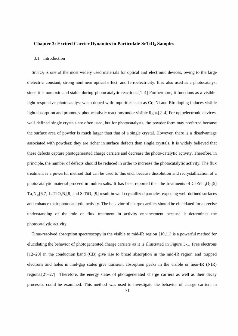
71
Chapter 3: Excited Carrier Dynamics in Particulate SrTiO3 Samples
3.1. Introduction
SrTiO3 is one of the most widely used materials for optical and electronic devices, owing to the large
dielectric constant, strong nonlinear optical effect, and ferroelectricity. It is also used as a photocatalyst
since it is nontoxic and stable during photocatalytic reactions.[1–4] Furthermore, it functions as a visible-
light-responsive photocatalyst when doped with impurities such as Cr, Ni and Rh: doping induces visible
light absorption and promotes photocatalytic reactions under visible light.[2–4] For optoelectronic devices,
well defined single crystals are often used, but for photocatalysts, the powder form may preferred because
the surface area of powder is much larger than that of a single crystal. However, there is a disadvantage
associated with powders: they are richer in surface defects than single crystals. It is widely believed that
these defects capture photogenerated charge carriers and decrease the photo-catalytic activity. Therefore, in
principle, the number of defects should be reduced in order to increase the photocatalytic activity. The flux
treatment is a powerful method that can be used to this end, because dissolution and recrystallization of a
photocatalytic material proceed in molten salts. It has been reported that the treatments of CaZrTi2O7,[5]
Ta3N5,[6,7] LaTiO2N,[8] and SrTiO3,[9] result in well-crystallized particles exposing well-defined surfaces
and enhance their photocatalytic activity. The behavior of charge carriers should be elucidated for a precise
understanding of the role of flux treatment in activity enhancement because it determines the
photocatalytic activity.
Time-resolved absorption spectroscopy in the visible to mid-IR region [10,11] is a powerful method for
elucidating the behavior of photogenerated charge carriers as it is illustrated in Figure 3-1. Free electrons
[12–20] in the conduction band (CB) give rise to broad absorption in the mid-IR region and trapped
electrons and holes in mid-gap states give transient absorption peaks in the visible or near-IR (NIR)
regions.[21–27] Therefore, the energy states of photogenerated charge carriers as well as their decay
processes could be examined. This method was used to investigate the behavior of charge carriers in
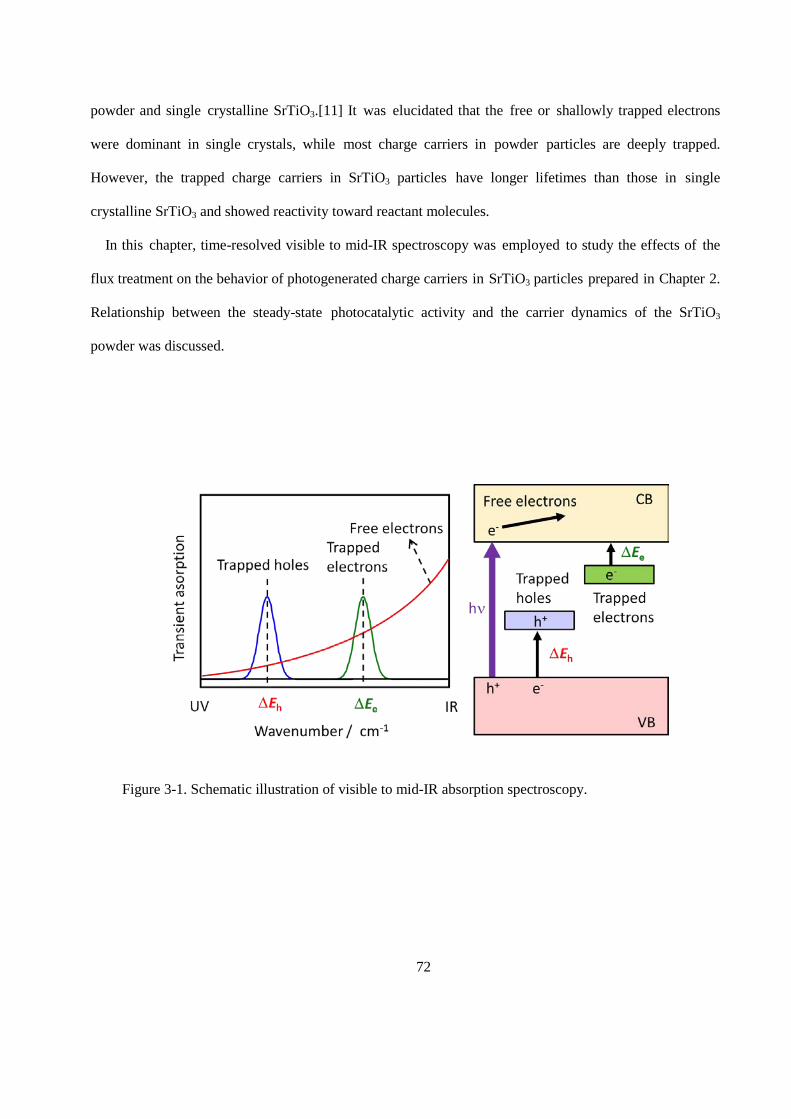
72
powder and single crystalline SrTiO3.[11] It was elucidated that the free or shallowly trapped electrons
were dominant in single crystals, while most charge carriers in powder particles are deeply trapped.
However, the trapped charge carriers in SrTiO3 particles have longer lifetimes than those in single
crystalline SrTiO3 and showed reactivity toward reactant molecules.
In this chapter, time-resolved visible to mid-IR spectroscopy was employed to study the effects of the
flux treatment on the behavior of photogenerated charge carriers in SrTiO3 particles prepared in Chapter 2.
Relationship between the steady-state photocatalytic activity and the carrier dynamics of the SrTiO3
powder was discussed.
Figure 3-1. Schematic illustration of visible to mid-IR absorption spectroscopy.
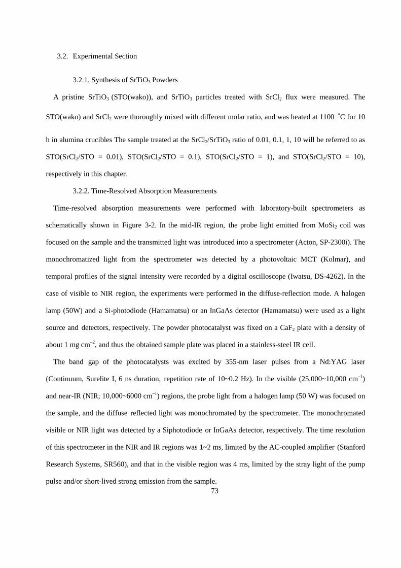
73
3.2. Experimental Section
3.2.1. Synthesis of SrTiO3 Powders
A pristine SrTiO3 (STO(wako)), and SrTiO3 particles treated with SrCl2 flux were measured. The
STO(wako) and SrCl2 were thoroughly mixed with different molar ratio, and was heated at 1100 ˚C for 10
h in alumina crucibles The sample treated at the SrCl2/SrTiO3 ratio of 0.01, 0.1, 1, 10 will be referred to as
STO(SrCl2/STO = 0.01), STO(SrCl2/STO = 0.1), STO(SrCl2/STO = 1), and STO(SrCl2/STO = 10),
respectively in this chapter.
3.2.2. Time-Resolved Absorption Measurements
Time-resolved absorption measurements were performed with laboratory-built spectrometers as
schematically shown in Figure 3-2. In the mid-IR region, the probe light emitted from MoSi2 coil was
focused on the sample and the transmitted light was introduced into a spectrometer (Acton, SP-2300i). The
monochromatized light from the spectrometer was detected by a photovoltaic MCT (Kolmar), and
temporal profiles of the signal intensity were recorded by a digital oscilloscope (Iwatsu, DS-4262). In the
case of visible to NIR region, the experiments were performed in the diffuse-reflection mode. A halogen
lamp (50W) and a Si-photodiode (Hamamatsu) or an InGaAs detector (Hamamatsu) were used as a light
source and detectors, respectively. The powder photocatalyst was fixed on a CaF2 plate with a density of
about 1 mg cm–2, and thus the obtained sample plate was placed in a stainless-steel IR cell.
The band gap of the photocatalysts was excited by 355-nm laser pulses from a Nd:YAG laser
(Continuum, Surelite I, 6 ns duration, repetition rate of 10~0.2 Hz). In the visible (25,000~10,000 cm–1)
and near-IR (NIR; 10,000~6000 cm–1) regions, the probe light from a halogen lamp (50 W) was focused on
the sample, and the diffuse reflected light was monochromated by the spectrometer. The monochromated
visible or NIR light was detected by a Siphotodiode or InGaAs detector, respectively. The time resolution
of this spectrometer in the NIR and IR regions was 1~2 ms, limited by the AC-coupled amplifier (Stanford
Research Systems, SR560), and that in the visible region was 4 ms, limited by the stray light of the pump
pulse and/or short-lived strong emission from the sample.
74
Figure 3-2. Illustration of the laboratory-built microsecond time-resolved visible, NIR and IR
absorption spectrometers.
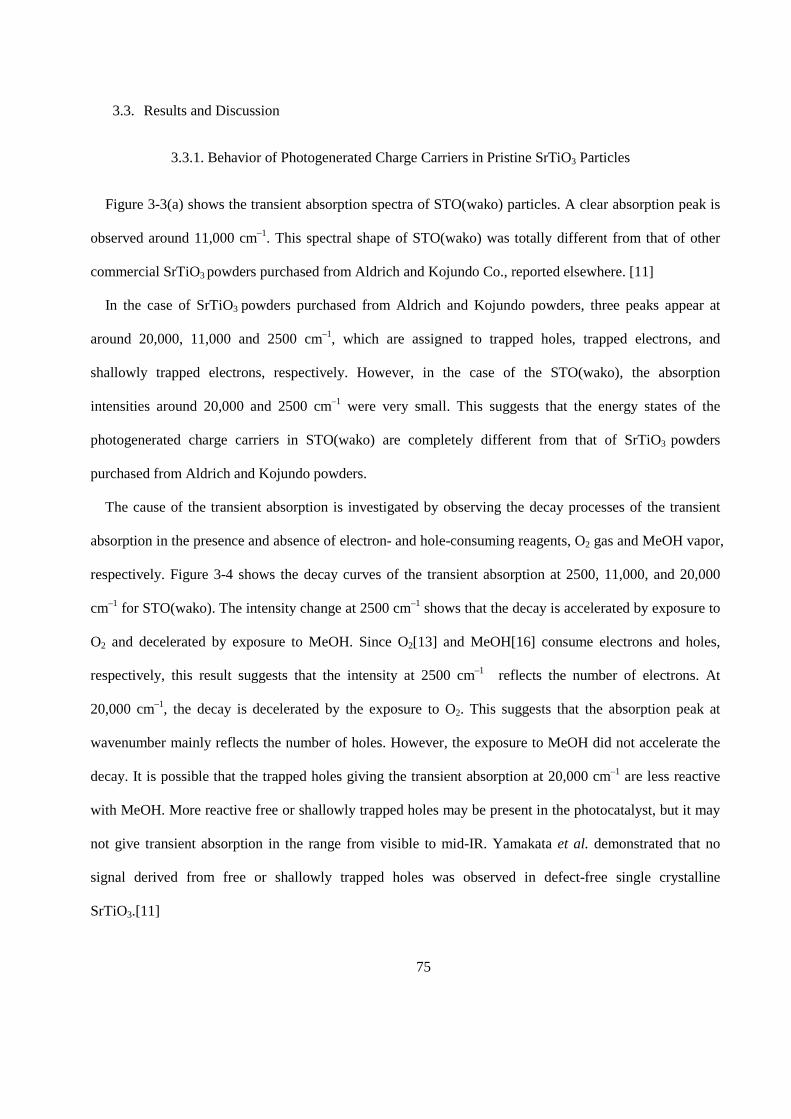
75
3.3. Results and Discussion
3.3.1. Behavior of Photogenerated Charge Carriers in Pristine SrTiO3 Particles
Figure 3-3(a) shows the transient absorption spectra of STO(wako) particles. A clear absorption peak is
observed around 11,000 cm–1. This spectral shape of STO(wako) was totally different from that of other
commercial SrTiO3 powders purchased from Aldrich and Kojundo Co., reported elsewhere. [11]
In the case of SrTiO3 powders purchased from Aldrich and Kojundo powders, three peaks appear at
around 20,000, 11,000 and 2500 cm–1, which are assigned to trapped holes, trapped electrons, and
shallowly trapped electrons, respectively. However, in the case of the STO(wako), the absorption
intensities around 20,000 and 2500 cm–1 were very small. This suggests that the energy states of the
photogenerated charge carriers in STO(wako) are completely different from that of SrTiO3 powders
purchased from Aldrich and Kojundo powders.
The cause of the transient absorption is investigated by observing the decay processes of the transient
absorption in the presence and absence of electron- and hole-consuming reagents, O2 gas and MeOH vapor,
respectively. Figure 3-4 shows the decay curves of the transient absorption at 2500, 11,000, and 20,000
cm–1 for STO(wako). The intensity change at 2500 cm–1 shows that the decay is accelerated by exposure to
O2 and decelerated by exposure to MeOH. Since O2[13] and MeOH[16] consume electrons and holes,
respectively, this result suggests that the intensity at 2500 cm–1 reflects the number of electrons. At
20,000 cm–1, the decay is decelerated by the exposure to O2. This suggests that the absorption peak at
wavenumber mainly reflects the number of holes. However, the exposure to MeOH did not accelerate the
decay. It is possible that the trapped holes giving the transient absorption at 20,000 cm–1 are less reactive
with MeOH. More reactive free or shallowly trapped holes may be present in the photocatalyst, but it may
not give transient absorption in the range from visible to mid-IR. Yamakata et al. demonstrated that no
signal derived from free or shallowly trapped holes was observed in defect-free single crystalline
SrTiO3.[11]
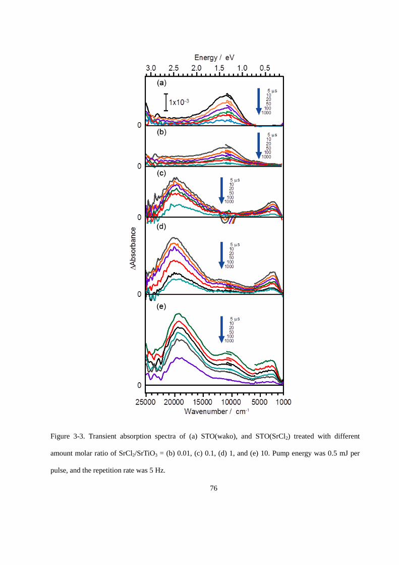
76
Figure 3-3. Transient absorption spectra of (a) STO(wako), and STO(SrCl2) treated with different
amount molar ratio of SrCl2/SrTiO3 = (b) 0.01, (c) 0.1, (d) 1, and (e) 10. Pump energy was 0.5 mJ per
pulse, and the repetition rate was 5 Hz.
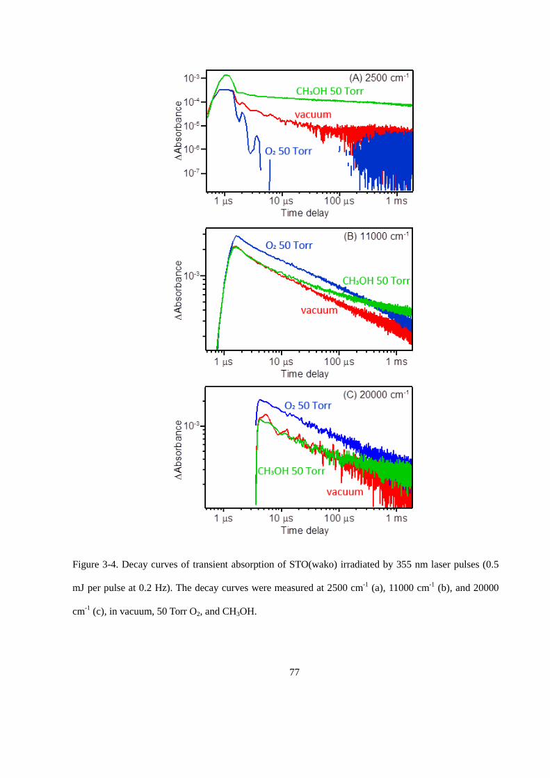
77
Figure 3-4. Decay curves of transient absorption of STO(wako) irradiated by 355 nm laser pulses (0.5
mJ per pulse at 0.2 Hz). The decay curves were measured at 2500 cm-1 (a), 11000 cm-1 (b), and 20000
cm-1 (c), in vacuum, 50 Torr O2, and CH3OH.
78
The intensity at 11,000 cm–1 exhibited complex changes: as shown in Figure 3-4(b), exposures to MeOH
and O2 vapors both decelerated the transient decay. This suggests that the band intensity at 11,000 cm–1
involves contributions from both photogenerated electrons and holes. This result can be explained as
follows: the hole-consuming reaction decreases the number of holes but increases the number of surviving
electrons, and vice versa. Numerical simulation [13] is useful to understand these phenomena. Therefore,
the decay curves of the number of electrons and holes are calculated based on a simple model. As
discussed in previous studies [10,12–14], the decay of carriers in microsecond regions follow the first-
order law, suggesting that the number of electron–hole pair is less than one pair per one particle. In this
case, the recombination should be represented as in equation 4.1 [13], where e–h is the electron–hole pair
existing in SrTiO3 particles, and k1 is the rate constant of recombination. On the other hand, the electron
and hole-consuming reactions by adsorbed O2 and methoxy species (MeO) derived from adsorbed MeOH
should be represented by equation 4.2 and 4.3, respectively, where k2 and k3 are the rate constants, and es
and hs represent the electron and hole separated from electron–hole pair in SrTiO3 particles, respectively.
The variable k2[O2] and k3[MeO] could be replaced by k2´ and k3´ for the simplicity. Then the rate equation
for electron–hole pair and separated electron could be represented as in equation 4.4 and 4.5, respectively.
e − h 𝑘𝑘1→ ℎ𝜈𝜈 𝑎𝑎𝑎𝑎𝑎𝑎 Δ (4.1)
e − h + 𝑂𝑂2(𝑎𝑎)𝑘𝑘2→ℎ𝑒𝑒
+ + 𝑂𝑂2−(𝑎𝑎) 𝑎𝑎𝑎𝑎𝑎𝑎 𝑒𝑒𝑒𝑒− + 𝑂𝑂2(𝑎𝑎)𝑘𝑘2→𝑂𝑂2−(𝑎𝑎) (4.2)
e − h +𝑀𝑀𝑒𝑒𝑂𝑂−(𝑎𝑎)𝑘𝑘3→𝑒𝑒𝑒𝑒− + 𝑀𝑀𝑒𝑒𝑂𝑂●(𝑎𝑎) 𝑎𝑎𝑎𝑎𝑎𝑎 ℎ𝑒𝑒
+ + 𝑀𝑀𝑒𝑒𝑂𝑂−(𝑎𝑎)𝑘𝑘3→𝑀𝑀𝑒𝑒𝑂𝑂●(𝑎𝑎) (4.3)
𝑟𝑟[e−h]𝑟𝑟𝑟𝑟
= −(𝑘𝑘1 + 𝑘𝑘2′ + 𝑘𝑘3
′)[e− h] (4.4)
𝑟𝑟[𝑁𝑁𝑠𝑠]𝑟𝑟𝑟𝑟
= 𝑘𝑘3′[e− h] − 𝑘𝑘2
′[𝑒𝑒𝑒𝑒] (4.5)
For the simplicity of the model, it could be assumed that the single component of recombination and
initial values at time zero were set to [e – h] = 1, [es] = [hs] = 0. The decay curves in a vacuum were
calculated by setting the rate constants to k1 = 0.01, k2´ = k3´ = 0. In the presence of O2, k2´ was changed to
0.002. The calculated [e-] = [e – h] + [es], [h+] = [e – h] + [hs], and the sum of [e-] and [h+] are shown in
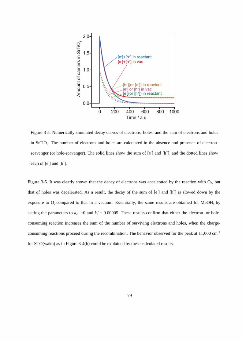
79
Figure 3-5. It was clearly shown that the decay of electrons was accelerated by the reaction with O2, but
that of holes was decelerated. As a result, the decay of the sum of [e-] and [h+] is slowed down by the
exposure to O2 compared to that in a vacuum. Essentially, the same results are obtained for MeOH, by
setting the parameters to k2´ =0 and k3´= 0.00005. These results confirm that either the electron- or hole-
consuming reaction increases the sum of the number of surviving electrons and holes, when the charge-
consuming reactions proceed during the recombination. The behavior observed for the peak at 11,000 cm–1
for STO(wako) as in Figure 3-4(b) could be explained by these calculated results.
Figure 3-5. Numerically simulated decay curves of electrons, holes, and the sum of electrons and holes
in SrTiO3. The number of electrons and holes are calculated in the absence and presence of electron-
scavenger (or hole-scavenger). The solid lines show the sum of [e-] and [h+], and the dotted lines show
each of [e-] and [h+].
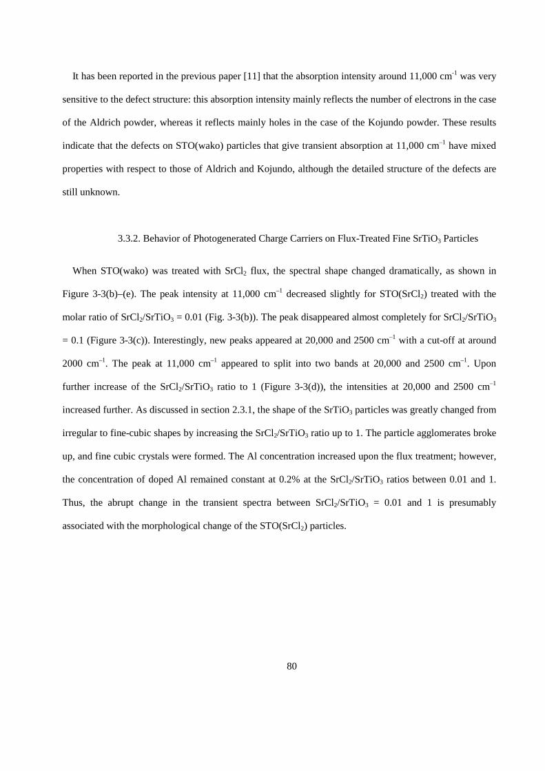
80
It has been reported in the previous paper [11] that the absorption intensity around 11,000 cm-1 was very
sensitive to the defect structure: this absorption intensity mainly reflects the number of electrons in the case
of the Aldrich powder, whereas it reflects mainly holes in the case of the Kojundo powder. These results
indicate that the defects on STO(wako) particles that give transient absorption at 11,000 cm–1 have mixed
properties with respect to those of Aldrich and Kojundo, although the detailed structure of the defects are
still unknown.
3.3.2. Behavior of Photogenerated Charge Carriers on Flux-Treated Fine SrTiO3 Particles
When STO(wako) was treated with SrCl2 flux, the spectral shape changed dramatically, as shown in
Figure 3-3(b)–(e). The peak intensity at 11,000 cm–1 decreased slightly for STO(SrCl2) treated with the
molar ratio of SrCl2/SrTiO3 = 0.01 (Fig. 3-3(b)). The peak disappeared almost completely for SrCl2/SrTiO3
= 0.1 (Figure 3-3(c)). Interestingly, new peaks appeared at 20,000 and 2500 cm–1 with a cut-off at around
2000 cm–1. The peak at 11,000 cm–1 appeared to split into two bands at 20,000 and 2500 cm–1. Upon
further increase of the SrCl2/SrTiO3 ratio to 1 (Figure 3-3(d)), the intensities at 20,000 and 2500 cm–1
increased further. As discussed in section 2.3.1, the shape of the SrTiO3 particles was greatly changed from
irregular to fine-cubic shapes by increasing the SrCl2/SrTiO3 ratio up to 1. The particle agglomerates broke
up, and fine cubic crystals were formed. The Al concentration increased upon the flux treatment; however,
the concentration of doped Al remained constant at 0.2% at the SrCl2/SrTiO3 ratios between 0.01 and 1.
Thus, the abrupt change in the transient spectra between SrCl2/SrTiO3 = 0.01 and 1 is presumably
associated with the morphological change of the STO(SrCl2) particles.
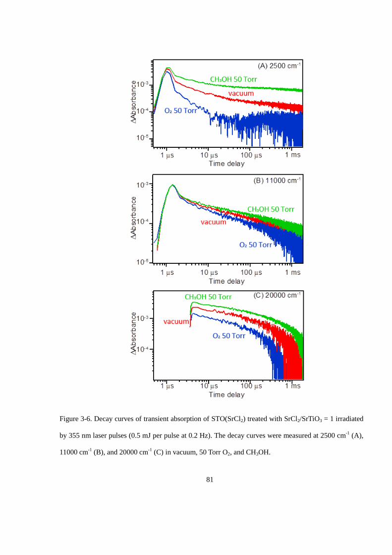
81
Figure 3-6. Decay curves of transient absorption of STO(SrCl2) treated with SrCl2/SrTiO3 = 1 irradiated
by 355 nm laser pulses (0.5 mJ per pulse at 0.2 Hz). The decay curves were measured at 2500 cm-1 (A),
11000 cm-1 (B), and 20000 cm-1 (C) in vacuum, 50 Torr O2, and CH3OH.
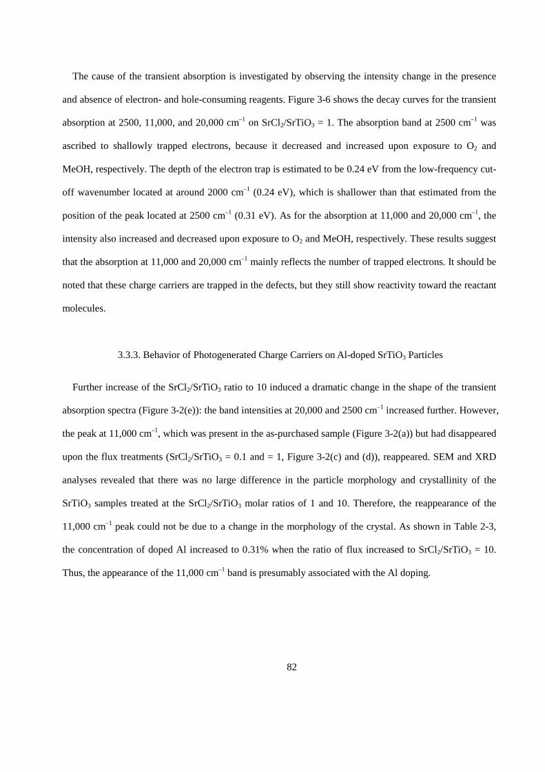
82
The cause of the transient absorption is investigated by observing the intensity change in the presence
and absence of electron- and hole-consuming reagents. Figure 3-6 shows the decay curves for the transient
absorption at 2500, 11,000, and 20,000 cm–1 on SrCl2/SrTiO3 = 1. The absorption band at 2500 cm–1 was
ascribed to shallowly trapped electrons, because it decreased and increased upon exposure to O2 and
MeOH, respectively. The depth of the electron trap is estimated to be 0.24 eV from the low-frequency cut-
off wavenumber located at around 2000 cm–1 (0.24 eV), which is shallower than that estimated from the
position of the peak located at 2500 cm–1 (0.31 eV). As for the absorption at 11,000 and 20,000 cm–1, the
intensity also increased and decreased upon exposure to O2 and MeOH, respectively. These results suggest
that the absorption at 11,000 and 20,000 cm–1 mainly reflects the number of trapped electrons. It should be
noted that these charge carriers are trapped in the defects, but they still show reactivity toward the reactant
molecules.
3.3.3. Behavior of Photogenerated Charge Carriers on Al-doped SrTiO3 Particles
Further increase of the SrCl2/SrTiO3 ratio to 10 induced a dramatic change in the shape of the transient
absorption spectra (Figure 3-2(e)): the band intensities at 20,000 and 2500 cm–1 increased further. However,
the peak at 11,000 cm–1, which was present in the as-purchased sample (Figure 3-2(a)) but had disappeared
upon the flux treatments (SrCl2/SrTiO3 = 0.1 and = 1, Figure 3-2(c) and (d)), reappeared. SEM and XRD
analyses revealed that there was no large difference in the particle morphology and crystallinity of the
SrTiO3 samples treated at the SrCl2/SrTiO3 molar ratios of 1 and 10. Therefore, the reappearance of the
11,000 cm–1 peak could not be due to a change in the morphology of the crystal. As shown in Table 2-3,
the concentration of doped Al increased to 0.31% when the ratio of flux increased to SrCl2/SrTiO3 = 10.
Thus, the appearance of the 11,000 cm–1 band is presumably associated with the Al doping.
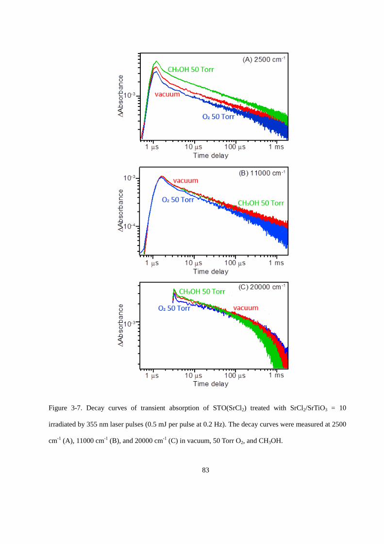
83
Figure 3-7. Decay curves of transient absorption of STO(SrCl2) treated with SrCl2/SrTiO3 = 10
irradiated by 355 nm laser pulses (0.5 mJ per pulse at 0.2 Hz). The decay curves were measured at 2500
cm-1 (A), 11000 cm-1 (B), and 20000 cm-1 (C) in vacuum, 50 Torr O2, and CH3OH.
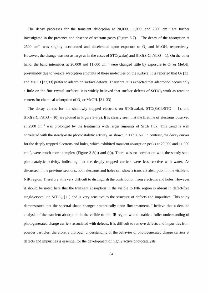
84
The decay processes for the transient absorption at 20,000, 11,000, and 2500 cm–1 are further
investigated in the presence and absence of reactant gases (Figure 3-7). The decay of the absorption at
2500 cm–1 was slightly accelerated and decelerated upon exposure to O2 and MeOH, respectively.
However, the change was not as large as in the cases of STO(wako) and STO(SrCl2/STO = 1). On the other
hand, the band intensities at 20,000 and 11,000 cm–1 were changed little by exposure to O2 or MeOH,
presumably due to weakre adsorption amounts of these molecules on the surface. It is reported that O2 [31]
and MeOH [32,33] prefer to adsorb on surface defects. Therefore, it is expected that adsorption occurs only
a little on the fine crystal surfaces: it is widely believed that surface defects of SrTiO3 work as reaction
centers for chemical adsorption of O2 or MeOH. [31–33]
The decay curves for the shallowly trapped electrons on STO(wako), STO(SrCl2/STO = 1), and
STO(SrCl2/STO = 10) are plotted in Figure 3-8(a). It is clearly seen that the lifetime of electrons observed
at 2500 cm–1 was prolonged by the treatments with larger amounts of SrCl2 flux. This trend is well
correlated with the steady-state photocatalytic activity, as shown in Table 2-2. In contrast, the decay curves
for the deeply trapped electrons and holes, which exhibited transient absorption peaks at 20,000 and 11,000
cm–1, were much more complex (Figure 3-8(b) and (c)). There was no correlation with the steady-state
photocatalytic activity, indicating that the deeply trapped carriers were less reactive with water. As
discussed in the previous sections, both electrons and holes can show a transient absorption in the visible to
NIR region. Therefore, it is very difficult to distinguish the contribution from electrons and holes. However,
it should be noted here that the transient absorption in the visible to NIR region is absent in defect-free
single-crystalline SrTiO3 [11] and is very sensitive to the structure of defects and impurities. This study
demonstrates that the spectral shape changes dramatically upon flux treatment. I believe that a detailed
analysis of the transient absorption in the visible to mid-IR region would enable a fuller understanding of
photogenerated charge carriers associated with defects. It is difficult to remove defects and impurities from
powder particles; therefore, a thorough understanding of the behavior of photogenerated charge carriers at
defects and impurities is essential for the development of highly active photocatalysts.
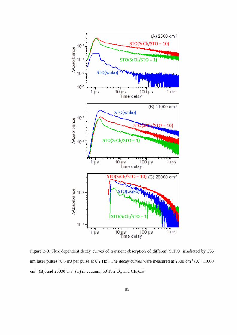
85
Figure 3-8. Flux dependent decay curves of transient absorption of different SrTiO3 irradiated by 355
nm laser pulses (0.5 mJ per pulse at 0.2 Hz). The decay curves were measured at 2500 cm-1 (A), 11000
cm-1 (B), and 20000 cm-1 (C) in vacuum, 50 Torr O2, and CH3OH.
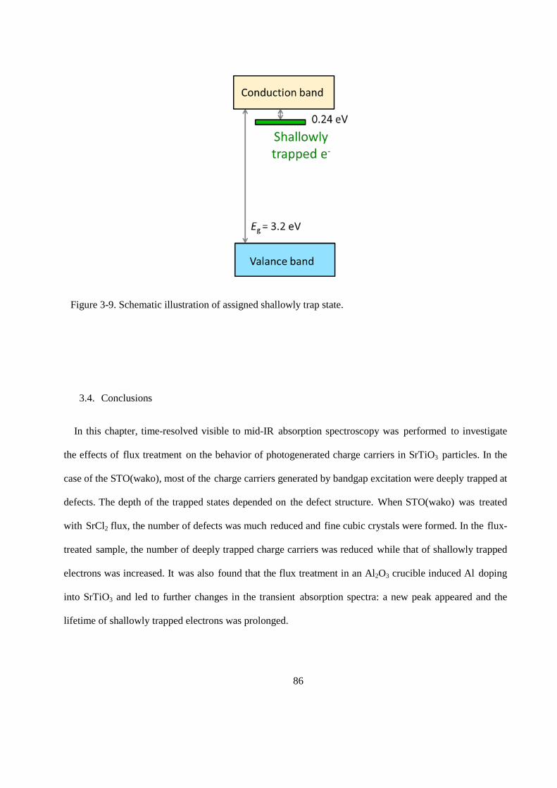
86
3.4. Conclusions
In this chapter, time-resolved visible to mid-IR absorption spectroscopy was performed to investigate
the effects of flux treatment on the behavior of photogenerated charge carriers in SrTiO3 particles. In the
case of the STO(wako), most of the charge carriers generated by bandgap excitation were deeply trapped at
defects. The depth of the trapped states depended on the defect structure. When STO(wako) was treated
with SrCl2 flux, the number of defects was much reduced and fine cubic crystals were formed. In the flux-
treated sample, the number of deeply trapped charge carriers was reduced while that of shallowly trapped
electrons was increased. It was also found that the flux treatment in an Al2O3 crucible induced Al doping
into SrTiO3 and led to further changes in the transient absorption spectra: a new peak appeared and the
lifetime of shallowly trapped electrons was prolonged.
Figure 3-9. Schematic illustration of assigned shallowly trap state.
87
References
[1] K. Domen, S. Naito, M. Soma, T. Onishi, and K. Tamaru, “Photocatalytic decomposition of water
vapour on an NiO–SrTiO3 catalyst,” Journal of the Chemical Society, Chemical Communications,
no. 12, pp. 543–544, 1980.
[2] A. Kudo and Y. Miseki, “Heterogeneous photocatalyst materials for water splitting,” Chemical Society
Reviews, vol. 38, no. 1, pp. 253–278, 2009.
[3] H. Kato and A. Kudo, “Visible-light-response and photocatalytic activities of TiO2 and SrTiO3
photocatalysts codoped with antimony and chromium,” The Journal of Physical Chemistry B, vol. 106, no.
19, pp. 5029–5034, 2002.
[4] K. Furuhashi, Q. Jia, A. Kudo, and H. Onishi, “Time-resolved infrared absorption study of SrTiO3
photocatalysts codoped with rhodium and antimony,” The Journal of Physical Chemistry C, vol. 117, no.
37, pp. 19 101–19 106, 2013.
[5] Y. Miseki, K. Saito, and A. Kudo, “Nanocrystalline CaZrTi2O7 photocatalyst prepared by a
polymerizable complex method in the presence of Cs2CO3 flux for water splitting,” Chemistry Letters, vol.
38, no. 2, pp. 180–181, 2009.
[6] T. Takata, D. Lu, and K. Domen, “Synthesis of structurally defined Ta3N5 particles by flux-assisted
nitridation,” Crystal Growth & Design, vol. 11, no. 1, pp. 33–38, 2011.
[7] S. S. K. Ma, T. Hisatomi, K. Maeda, Y. Moriya, and K. Domen, “Enhanced water oxidation on Ta3N5
photocatalysts by modification with alkaline metal salts,” Journal of the American Chemical Society, vol.
134, no. 49, pp. 19 993–19 996, 2012.
[8] F. Zhang, A. Yamakata, K. Maeda, Y. Moriya, T. Takata, J. Kubota, K. Teshima, S. Oishi, and K.
Domen, “Cobalt-modified porous single-crystalline LaTiO2N for highly efficient water oxidation under
visible light,” Journal of the American Chemical Society, vol. 134, no. 20, pp. 8348–8351, 2012.
88
[9] H. Kato, M. Kobayashi, M. Hara, and M. Kakihana, “Fabrication of SrTiO3 exposing characteristic
facets using molten salt flux and improvement of photocatalytic activity for water splitting,” Catalysis
Science & Technology, vol. 3, no. 7, pp. 1733–1738, 2013.
[10] A. Yamakata, M. Kawaguchi, N. Nishimura, T. Minegishi, J. Kubota, and K. Domen, “Behavior and
energy states of Photogenerated charge carriers on Pt- or CoOx-loaded LaTiO2N photocatalysts: Time-
resolved visible to mid-infrared absorption study,” The Journal of Physical Chemistry C, vol. 118, no. 41,
pp. 23 897–23 906, 2014.
[11] A. Yamakata, J. J. M. Vequizo, and M. Kawaguchi, “Behavior and energy state of photogenerated
charge carriers in single-crystalline and polycrystalline powder SrTiO3 studied by time-resolved absorption
spectroscopy in the visible to mid-infrared region,” The Journal of Physical Chemistry C, vol. 119, no. 4,
pp. 1880–1885, 2015.
[12] A. Yamakata, T. Ishibashi, and H. Onishi, “Time-resolved infrared absorption spectroscopy of
photogenerated electrons in platinized TiO2 particles,” Chemical Physics Letters, vol. 333, no. 3, pp. 271–
277, 2001.
[13] A. Yamakata, T. Ishibashi, and H. Onishi, “Water-and oxygen-induced decay kinetics of
Photogenerated electrons in TiO2 and Pt/TiO2: a time-resolved infrared absorption study,” The Journal of
Physical Chemistry B, vol. 105, no. 30, pp. 7258–7262, 2001.
[14] A. Yamakata, T. Ishibashi, H. Kato, A. Kudo, and H. Onishi, “Photodynamics of NaTaO3 catalysts for
efficient water splitting,” The Journal of Physical Chemistry B, vol. 107, no. 51, pp. 14 383–14 387, 2003.
[15] A. Yamakata, M. Yoshida, J. Kubota, M. Osawa, and K. Domen, “Potential-dependent recombination
kinetics of photogenerated electrons in n-and p-type GaN photoelectrodes studied by time-resolved IR
absorption spectroscopy,” Journal of the American Chemical Society, vol. 133, no. 29, pp. 11 351–11 357,
2011.
89
[16] A. Yamakata, T. Ishibashi, and H. Onishi, “Electron-and hole-capture reactions on Pt/TiO2
photocatalyst exposed to methanol vapor studied with time-resolved infrared absorption spectroscopy,” The
Journal of Physical Chemistry B, vol. 106, no. 35, pp. 9122–9125, 2002.
[17] A. Yamakata, T. Ishibashi, and H. Onishi, “Effects of water addition on the methanol oxidation on
Pt/TiO2 photocatalyst studied by time-resolved infrared absorption spectroscopy,” The Journal of Physical
Chemistry B, vol. 107, no. 36, pp. 9820–9823, 2003.
[18] A. Yamakata, T. Ishibashi, and H. Onishi, “Microsecond kinetics of photocatalytic oxidation on
Pt/TiO2 traced by vibrational spectroscopy,” Chemical physics letters, vol. 376, no. 5, pp. 576–580, 2003.
[19] A. Yamakata, I. Takaaki, and H. Onishi, “Effects of accumulated electrons on the decay kinetics of
Photogenerated electrons in Pt/TiO2 photocatalyst studied by time-resolved infrared absorption
spectroscopy,” Journal of Photochemistry and Photobiology A: Chemistry, vol. 160, no. 1, pp. 33–36, 2003.
[20] T. Chen, Z. Feng, G. Wu, J. Shi, G. Ma, P. Ying, and C. Li, “Mechanistic studies of photocatalytic
reaction of methanol for hydrogen production on Pt/TiO2 by in situ fourier transform IR and time-resolved
IR spectroscopy,” The Journal of Physical Chemistry C, vol. 111, no. 22, pp. 8005–8014, 2007.
[21] B. H. Meekins and P. V. Kamat, “Role of water oxidation catalyst IrO2 in shuttling photogenerated
holes across TiO2 interface,” The Journal of Physical Chemistry Letters, vol. 2, no. 18, pp. 2304–2310,
2011.
[22] D. Bahnemann, A. Henglein, J. Lilie, and L. Spanhel, “Flash photolysis observation of the absorption
spectra of trapped positive holes and electrons in colloidal titanium dioxide,” The Journal of Physical
Chemistry, vol. 88, no. 4, pp. 709–711, 1984.
[23] D. W. Bahnemann, M. Hilgendorff, and R. Memming, “Charge carrier dynamics at TiO2 particles:
reactivity of free and trapped holes,” The Journal of Physical Chemistry B, vol. 101, no. 21, pp. 4265–4275,
1997.
[24] T. Yoshihara, R. Katoh, A. Furube, Y. Tamaki, M. Murai, K. Hara, S. Murata, H. Arakawa, and M.
Tachiya, “Identification of reactive species in photoexcited nanocrystalline TiO2 films by wide-
90
wavelength-range (400-2500 nm) transient absorption spectroscopy,” The Journal of Physical Chemistry B,
vol. 108, no. 12, pp. 3817–3823, 2004.
[25] Y. Tamaki, A. Furube, M. Murai, K. Hara, R. Katoh, and M. Tachiya, “Direct observation of reactive
trapped holes in TiO2 undergoing photocatalytic oxidation of adsorbed alcohols: evaluation of the reaction
rates and yields,” Journal of the American Chemical Society, vol. 128, no. 2, pp. 416–417, 2006.
[26] M. Barroso, A. J. Cowan, S. R. Pendlebury, M. Grätzel, D. R. Klug, and J. R. Durrant, “The role of
cobalt phosphate in enhancing the photocatalytic activity of α-Fe2O3 toward water oxidation,” Journal of
the American Chemical Society, vol. 133, no. 38, pp. 14 868–14 871, 2011.
[27] M. Barroso, C. A. Mesa, S. R. Pendlebury, A. J. Cowan, T. Hisatomi, K. Sivula, M. Grätzel, D. R.
Klug, and J. R. Durrant, “Dynamics of photogenerated holes in surface modified α-Fe2O3 photoanodes for
solar water splitting,” Proceedings of the National Academy of Sciences, vol. 109, no. 39, pp. 15 640–15
645, 2012.
[28] A. Yamakata, E. Soeta, T. Ishiyama, M. Osawa, and A. Morita, “Real-time observation of the
destruction of hydration shells under electrochemical force,” Journal of the American Chemical Society,
vol. 135, no. 40, pp. 15 033–15 039, 2013.
[29] K. Maeda, K. Teramura, H. Masuda, T. Takata, N. Saito, Y. Inoue, and K. Domen, “Efficient overall
water splitting under visible-light irradiation on (Ga1-xZnx)(N1-xOx) dispersed with Rh-Cr mixed-oxide
nanoparticles: Effect of reaction conditions on photocatalytic activity,” The Journal of Physical Chemistry
B, vol. 110, no. 26, pp. 13 107–13 112, 2006.
[30] T. Takata and K. Domen, “Defect engineering of photocatalysts by doping of aliovalent metal cations
for efficient water splitting,” The Journal of Physical Chemistry C, vol. 113, no. 45, pp. 19 386–19 388,
2009.
[31] H. Tanaka, T. Matsumoto, T. Kawai, and S. Kawai, “Interaction of oxygen vacancies with O2 on a
reduced SrTiO3(100)√5 × √5-R26.6˚surface observed by STM,” Surface science, vol. 318, no. 1, pp. 29–
38, 1994.

91
[32] T. Yoshikawa and M. Bowker, “Reductive coupling desorption of methanol on reduced SrTiO3(110),”
Phys. Chem. Chem. Phys., vol. 1, no. 5, pp. 913–920, 1999.
[33] L.-Q. Wang, K. F. Ferris, S. Azad, and M. H. Engelhard, “Adsorption and reaction of methanol on
stoichiometric and defective SrTiO3(110) surfaces,” The Journal of Physical Chemistry B, vol. 109, no. 10,
pp. 4507–4513, 2005.
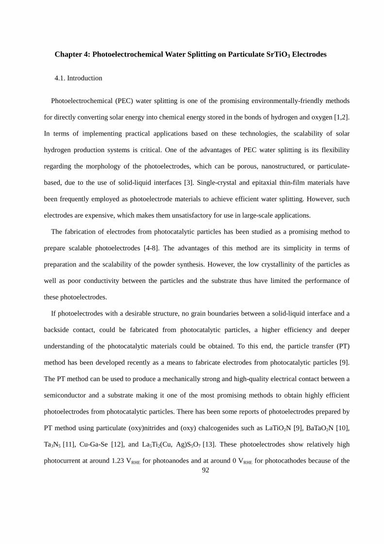
92
Chapter 4: Photoelectrochemical Water Splitting on Particulate SrTiO3 Electrodes
4.1. Introduction
Photoelectrochemical (PEC) water splitting is one of the promising environmentally-friendly methods
for directly converting solar energy into chemical energy stored in the bonds of hydrogen and oxygen [1,2].
In terms of implementing practical applications based on these technologies, the scalability of solar
hydrogen production systems is critical. One of the advantages of PEC water splitting is its flexibility
regarding the morphology of the photoelectrodes, which can be porous, nanostructured, or particulate-
based, due to the use of solid-liquid interfaces [3]. Single-crystal and epitaxial thin-film materials have
been frequently employed as photoelectrode materials to achieve efficient water splitting. However, such
electrodes are expensive, which makes them unsatisfactory for use in large-scale applications.
The fabrication of electrodes from photocatalytic particles has been studied as a promising method to
prepare scalable photoelectrodes [4-8]. The advantages of this method are its simplicity in terms of
preparation and the scalability of the powder synthesis. However, the low crystallinity of the particles as
well as poor conductivity between the particles and the substrate thus have limited the performance of
these photoelectrodes.
If photoelectrodes with a desirable structure, no grain boundaries between a solid-liquid interface and a
backside contact, could be fabricated from photocatalytic particles, a higher efficiency and deeper
understanding of the photocatalytic materials could be obtained. To this end, the particle transfer (PT)
method has been developed recently as a means to fabricate electrodes from photocatalytic particles [9].
The PT method can be used to produce a mechanically strong and high-quality electrical contact between a
semiconductor and a substrate making it one of the most promising methods to obtain highly efficient
photoelectrodes from photocatalytic particles. There has been some reports of photoelectrodes prepared by
PT method using particulate (oxy)nitrides and (oxy) chalcogenides such as LaTiO2N [9], BaTaO2N [10],
Ta3N5 [11], Cu-Ga-Se [12], and La5Ti2(Cu, Ag)S5O7 [13]. These photoelectrodes show relatively high
photocurrent at around 1.23 VRHE for photoanodes and at around 0 VRHE for photocathodes because of the
93
preferable structure of photoelectrode fabricated by PT method. However, their onset potential of
photocurrent are not sufficient because, considering the construction of overall water splitting system,
onset potentials of photoanode and photocathode need to be overlapped each other significantly. The
possible reasons of the limited PEC performance of the photoelectrodes prepared by PT method are the
crystallinities, surface properties, and structural feature of photocatalytic particles used in the
photoelectrodes.
In this chapter, PEC properties of photoanode prepared through PT method using particulate SrTiO3
developed in Chapter 2 are discussed. A study about the contact layer material revealed that the backside
contact have significant influence on the value and significant onset of photocurrent; formation of Schottky
barrier clearly hinder both onset potential and photocurrent especially at relatively low applied potential.
The SrTiO3 photoanode fabricated by PT method using proper contact layer and high quality of particles
showed comparable photocurrent to that of single crystalline wafer of Nb doped SrTiO3. I believe this is
the first report of the electrode prepared from semiconductor powders having a high activity as electrode
fabricated from single crystalline wafer of the same material.
4.2. Experimental Section
4.2.1. Synthesis of SrTiO3 Powders
A pristine SrTiO3(STO(wako)), a 1% Al doped SrTiO3 synthesized by solid state reaction (Al-STO(ssr)),
a SrTiO3 synthesized by flux method using SrCl2 in yttria crucible (STO(flux)), and a 1% Al doped SrTiO3
synthesized by flux method using SrCl2 in yttria crucible (Al-STO(flux)) were prepared as described in
section 2.2 and they were used for photoelectrode fabrication through PT method.
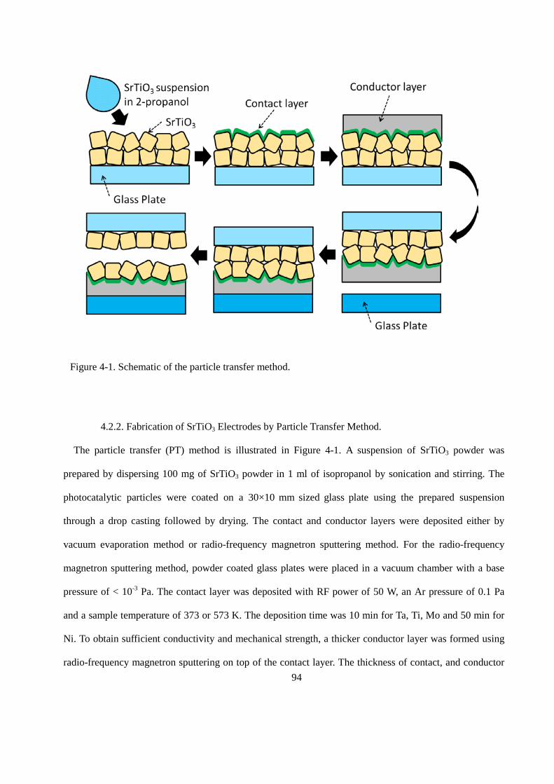
94
4.2.2. Fabrication of SrTiO3 Electrodes by Particle Transfer Method.
The particle transfer (PT) method is illustrated in Figure 4-1. A suspension of SrTiO3 powder was
prepared by dispersing 100 mg of SrTiO3 powder in 1 ml of isopropanol by sonication and stirring. The
photocatalytic particles were coated on a 30×10 mm sized glass plate using the prepared suspension
through a drop casting followed by drying. The contact and conductor layers were deposited either by
vacuum evaporation method or radio-frequency magnetron sputtering method. For the radio-frequency
magnetron sputtering method, powder coated glass plates were placed in a vacuum chamber with a base
pressure of < 10-3 Pa. The contact layer was deposited with RF power of 50 W, an Ar pressure of 0.1 Pa
and a sample temperature of 373 or 573 K. The deposition time was 10 min for Ta, Ti, Mo and 50 min for
Ni. To obtain sufficient conductivity and mechanical strength, a thicker conductor layer was formed using
radio-frequency magnetron sputtering on top of the contact layer. The thickness of contact, and conductor
Figure 4-1. Schematic of the particle transfer method.
95
layers were estimated to be 100~ 300 nm for contact, and ~5 µm for conductor layers, respectively. The
layers were bonded to another glass plate by adhesives, such as epoxy resin or double-sided tapes, and then
peeled off from the original glass plate. The excess particles on the electrode which are not contact with
contact layer directly were removed by ultra-sonication in water. Electrodes prepared from each type of
SrTiO3 will hereafter be referred to as STO(wako)/M, STO(flux)/M, Al-STO(flux)/M, and Al-STO(ssr)/M,
respectively, where M represents the type of metal used as a contact layer.
4.2.3. Fabrication of Electrodes from Single Crystalline SrTiO3 Wafer.
Single crystalline wafer of Nb doped SrTiO3 (Shinkosha Co. LTD., Nb 0.01wt%, 10 x 10 x 0.5 t mm,
polished on one side, (100)) was purchased and used without any pretreatment. The surface was cleansed
in acetone, followed by ethanol and distilled water. The contact layer was deposited on unpolished side of
the crystal. The electrodes prepared this way will hereafter be referred to as STO:Nb(SC)/M where M
represents the type of metal used as a contact layer.
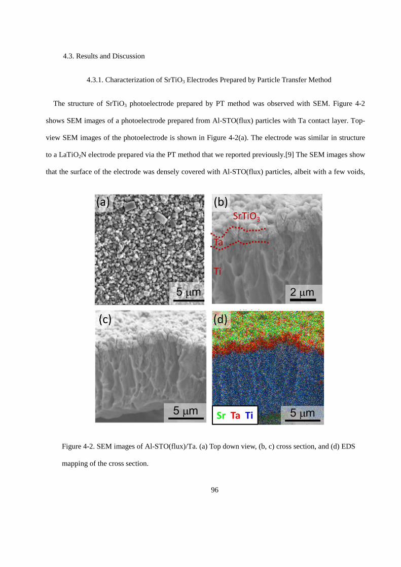
96
4.3. Results and Discussion
4.3.1. Characterization of SrTiO3 Electrodes Prepared by Particle Transfer Method
The structure of SrTiO3 photoelectrode prepared by PT method was observed with SEM. Figure 4-2
shows SEM images of a photoelectrode prepared from Al-STO(flux) particles with Ta contact layer. Top-
view SEM images of the photoelectrode is shown in Figure 4-2(a). The electrode was similar in structure
to a LaTiO2N electrode prepared via the PT method that we reported previously.[9] The SEM images show
that the surface of the electrode was densely covered with Al-STO(flux) particles, albeit with a few voids,
Figure 4-2. SEM images of Al-STO(flux)/Ta. (a) Top down view, (b, c) cross section, and (d) EDS
mapping of the cross section.
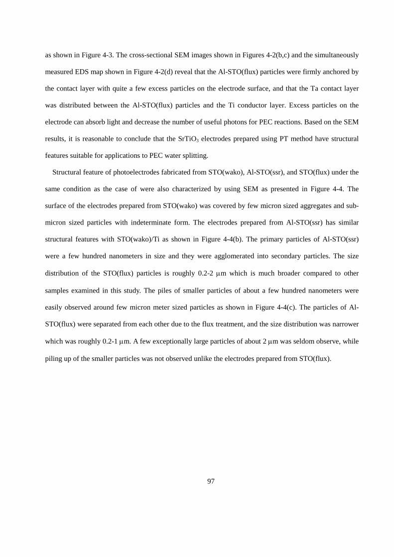
97
as shown in Figure 4-3. The cross-sectional SEM images shown in Figures 4-2(b,c) and the simultaneously
measured EDS map shown in Figure 4-2(d) reveal that the Al-STO(flux) particles were firmly anchored by
the contact layer with quite a few excess particles on the electrode surface, and that the Ta contact layer
was distributed between the Al-STO(flux) particles and the Ti conductor layer. Excess particles on the
electrode can absorb light and decrease the number of useful photons for PEC reactions. Based on the SEM
results, it is reasonable to conclude that the SrTiO3 electrodes prepared using PT method have structural
features suitable for applications to PEC water splitting.
Structural feature of photoelectrodes fabricated from STO(wako), Al-STO(ssr), and STO(flux) under the
same condition as the case of were also characterized by using SEM as presented in Figure 4-4. The
surface of the electrodes prepared from STO(wako) was covered by few micron sized aggregates and sub-
micron sized particles with indeterminate form. The electrodes prepared from Al-STO(ssr) has similar
structural features with STO(wako)/Ti as shown in Figure 4-4(b). The primary particles of Al-STO(ssr)
were a few hundred nanometers in size and they were agglomerated into secondary particles. The size
distribution of the STO(flux) particles is roughly 0.2-2 µm which is much broader compared to other
samples examined in this study. The piles of smaller particles of about a few hundred nanometers were
easily observed around few micron meter sized particles as shown in Figure 4-4(c). The particles of Al-
STO(flux) were separated from each other due to the flux treatment, and the size distribution was narrower
which was roughly 0.2-1 µm. A few exceptionally large particles of about 2 µm was seldom observe, while
piling up of the smaller particles was not observed unlike the electrodes prepared from STO(flux).
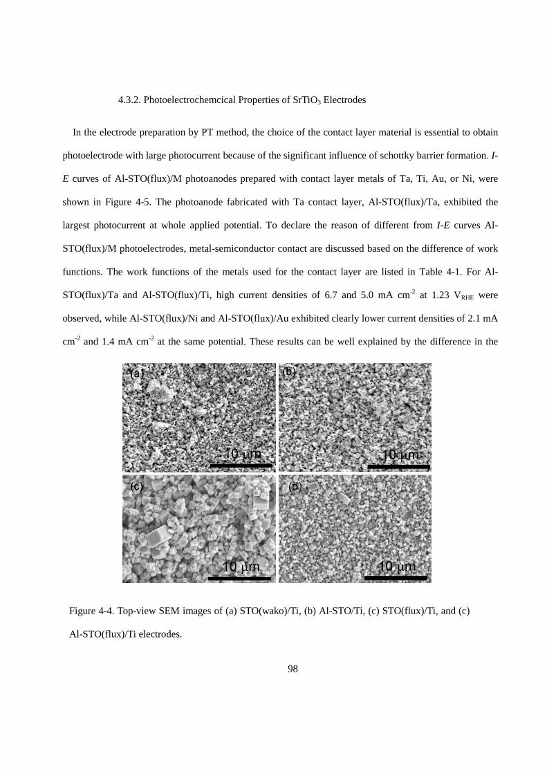
98
4.3.2. Photoelectrochemcical Properties of SrTiO3 Electrodes
In the electrode preparation by PT method, the choice of the contact layer material is essential to obtain
photoelectrode with large photocurrent because of the significant influence of schottky barrier formation. I-
E curves of Al-STO(flux)/M photoanodes prepared with contact layer metals of Ta, Ti, Au, or Ni, were
shown in Figure 4-5. The photoanode fabricated with Ta contact layer, Al-STO(flux)/Ta, exhibited the
largest photocurrent at whole applied potential. To declare the reason of different from I-E curves Al-
STO(flux)/M photoelectrodes, metal-semiconductor contact are discussed based on the difference of work
functions. The work functions of the metals used for the contact layer are listed in Table 4-1. For Al-
STO(flux)/Ta and Al-STO(flux)/Ti, high current densities of 6.7 and 5.0 mA cm-2 at 1.23 VRHE were
observed, while Al-STO(flux)/Ni and Al-STO(flux)/Au exhibited clearly lower current densities of 2.1 mA
cm-2 and 1.4 mA cm-2 at the same potential. These results can be well explained by the difference in the
Figure 4-4. Top-view SEM images of (a) STO(wako)/Ti, (b) Al-STO/Ti, (c) STO(flux)/Ti, and (c)
Al-STO(flux)/Ti electrodes.
99
band diagram at the metal-semiconductor contact due to the difference in work functions of the metals [14]
as illustrated in Figure 4-5.
The work function of SrTiO3 is reported to be about 4.2 eV [15], and its bandgap is reported to be about
3.2 eV [16]. When it forms a junction with a metal such as Au and Ni, which have significantly larger
work functions than that of SrTiO3, an obvious Schottky barrier should be formed at the metal-
semiconductor interface. This Schottky barrier exhibits rectification behavior, which prevents electron
transfer from the SrTiO3 to the metal. In contrast, the difference between the work functions of Ta and Ti
and that of SrTiO3 is negligible. Therefore, the Schottky barrier formed at the interfaces is negligible and
an ohmic-like contact that provides efficient electron transfer from SrTiO3.
Table 1. Work function of metals examined as contact layer [14].
Metal Work function / eV
Ta 4.25
Ti 4.33
Mo 4.60
Au 5.10
Ni 5.15
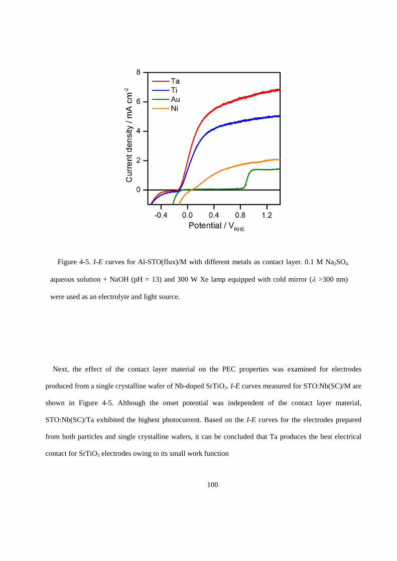
100
Next, the effect of the contact layer material on the PEC properties was examined for electrodes
produced from a single crystalline wafer of Nb-doped SrTiO3. I-E curves measured for STO:Nb(SC)/M are
shown in Figure 4-5. Although the onset potential was independent of the contact layer material,
STO:Nb(SC)/Ta exhibited the highest photocurrent. Based on the I-E curves for the electrodes prepared
from both particles and single crystalline wafers, it can be concluded that Ta produces the best electrical
contact for SrTiO3 electrodes owing to its small work function
Figure 4-5. I-E curves for Al-STO(flux)/M with different metals as contact layer. 0.1 M Na2SO4
aqueous solution + NaOH (pH = 13) and 300 W Xe lamp equipped with cold mirror (λ >300 nm)
were used as an electrolyte and light source.
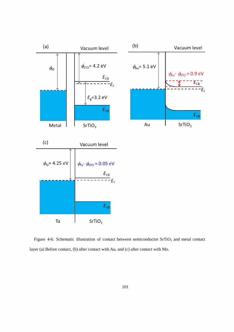
101
Figure 4-6. Schematic illustration of contact between semiconductor SrTiO3 and metal contact
layer (a) Before contact, (b) after contact with Au, and (c) after contact with Mo.
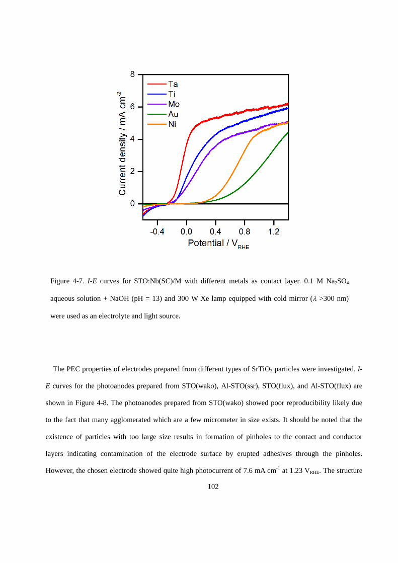
102
The PEC properties of electrodes prepared from different types of SrTiO3 particles were investigated. I-
E curves for the photoanodes prepared from STO(wako), Al-STO(ssr), STO(flux), and Al-STO(flux) are
shown in Figure 4-8. The photoanodes prepared from STO(wako) showed poor reproducibility likely due
to the fact that many agglomerated which are a few micrometer in size exists. It should be noted that the
existence of particles with too large size results in formation of pinholes to the contact and conductor
layers indicating contamination of the electrode surface by erupted adhesives through the pinholes.
However, the chosen electrode showed quite high photocurrent of 7.6 mA cm-1 at 1.23 VRHE. The structure
Figure 4-7. I-E curves for STO:Nb(SC)/M with different metals as contact layer. 0.1 M Na2SO4
aqueous solution + NaOH (pH = 13) and 300 W Xe lamp equipped with cold mirror (λ >300 nm)
were used as an electrolyte and light source.
103
of the electrodes prepared from Al-STO(ssr) powder was not much different from that of the electrodes
prepared from STO(wako) as shown in Figure 4-4 and the chosen electrode showed 7.2 mA cm-1, which
was comparable to the highest current density observed for STO(wako). The primary particles of Al-
STO(ssr) were a few hundred nanometers in size and they were agglomerated into secondary particles. The
electrode prepared from STO(flux) powder showed the lowest current density of 3 mA cm-1 at 1.23 VRHE
among the examined samples. The electrodes prepared from Al-STO(flux) powder showed photocurrent of
7.6 mA cm-1 at 1.23 VRHE which is one of the highest values along with STO(wako). Furthermore,
reproducibility of Al-STO(flux) based electrode was outstanding because of relatively small size
distribution of the particles.
As discussed above, the photocurrent for Al-STO based phtooanode was not saturated in the potential
range studied, likely due to the series resistance caused by its high resistivity. STO(wako) showed the
highest photocurrent among the samples investigated, while pristine STO showed the lowest photocatalytic
activity for overall water splitting as discussed in Chapter 2. The difference between the PEC properties
and the photocatalytic properties is likely due to the different mechanisms through which water splitting
takes place on these electrodes. In the case of PEC water splitting, photo-excited carriers in the
photocatalytic material are macroscopically separated by the band bending produced at the solid-liquid
interfaces. In contrast, in the case of photocatalysis, all of the reactions take place directly on the
photocatalytic particles. Thus, photocatalysis can be more sensitive to the surface conditions and does not
always require electrical conductivity and band bending. The difference in charge separation is one of the
possible reasons why a preferred synthesis method exists. It can be concluded that the unacceptably high
Al-STO resistivity is a reflection of its high crystallinity based on its surface and bulk properties, and that
the high crystallinity led to the higher photocatalytic activity.
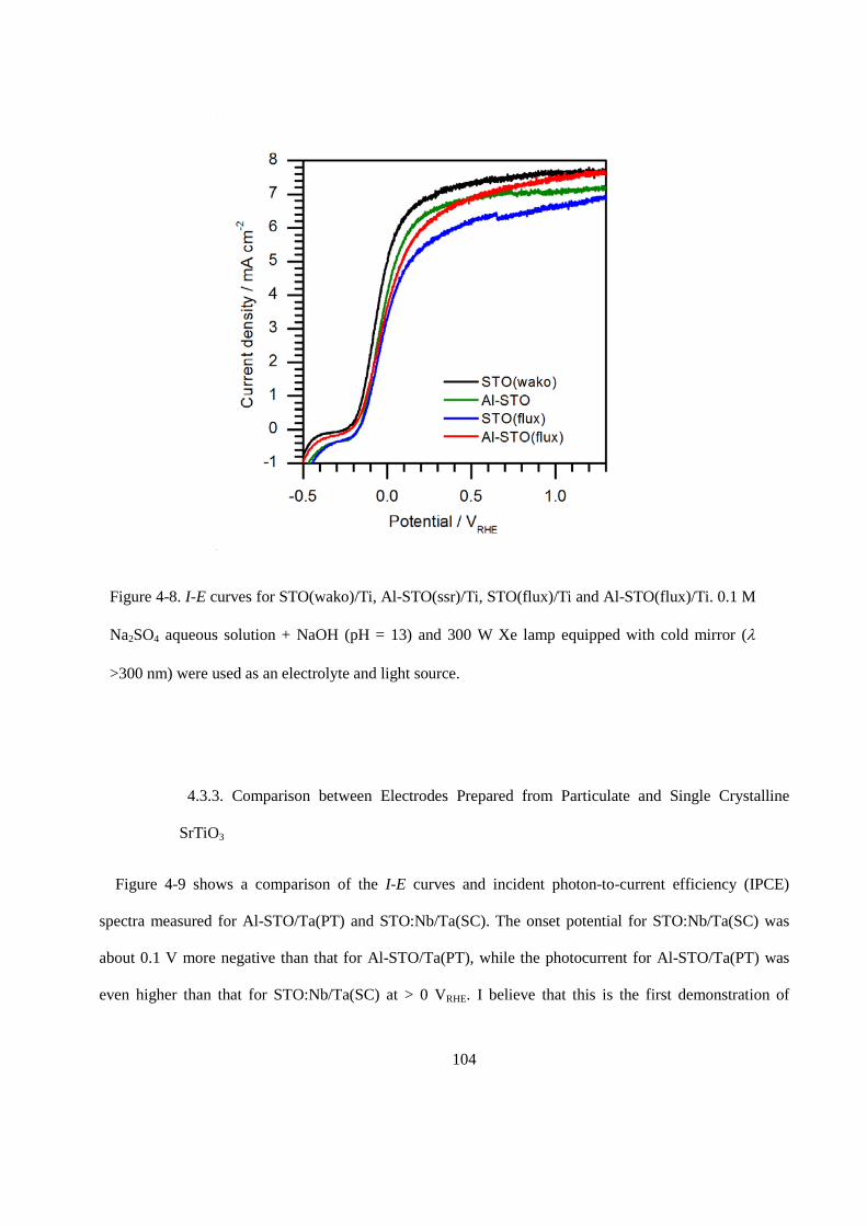
104
4.3.3. Comparison between Electrodes Prepared from Particulate and Single Crystalline
SrTiO3
Figure 4-9 shows a comparison of the I-E curves and incident photon-to-current efficiency (IPCE)
spectra measured for Al-STO/Ta(PT) and STO:Nb/Ta(SC). The onset potential for STO:Nb/Ta(SC) was
about 0.1 V more negative than that for Al-STO/Ta(PT), while the photocurrent for Al-STO/Ta(PT) was
even higher than that for STO:Nb/Ta(SC) at > 0 VRHE. I believe that this is the first demonstration of
Figure 4-8. I-E curves for STO(wako)/Ti, Al-STO(ssr)/Ti, STO(flux)/Ti and Al-STO(flux)/Ti. 0.1 M
Na2SO4 aqueous solution + NaOH (pH = 13) and 300 W Xe lamp equipped with cold mirror (λ
>300 nm) were used as an electrolyte and light source.
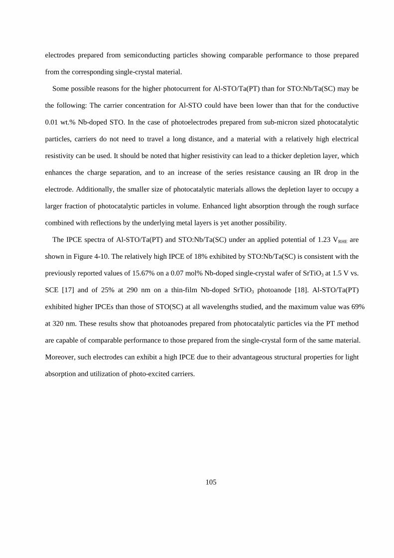
105
electrodes prepared from semiconducting particles showing comparable performance to those prepared
from the corresponding single-crystal material.
Some possible reasons for the higher photocurrent for Al-STO/Ta(PT) than for STO:Nb/Ta(SC) may be
the following: The carrier concentration for Al-STO could have been lower than that for the conductive
0.01 wt.% Nb-doped STO. In the case of photoelectrodes prepared from sub-micron sized photocatalytic
particles, carriers do not need to travel a long distance, and a material with a relatively high electrical
resistivity can be used. It should be noted that higher resistivity can lead to a thicker depletion layer, which
enhances the charge separation, and to an increase of the series resistance causing an IR drop in the
electrode. Additionally, the smaller size of photocatalytic materials allows the depletion layer to occupy a
larger fraction of photocatalytic particles in volume. Enhanced light absorption through the rough surface
combined with reflections by the underlying metal layers is yet another possibility.
The IPCE spectra of Al-STO/Ta(PT) and STO:Nb/Ta(SC) under an applied potential of 1.23 VRHE are
shown in Figure 4-10. The relatively high IPCE of 18% exhibited by STO:Nb/Ta(SC) is consistent with the
previously reported values of 15.67% on a 0.07 mol% Nb-doped single-crystal wafer of SrTiO3 at 1.5 V vs.
SCE [17] and of 25% at 290 nm on a thin-film Nb-doped SrTiO3 photoanode [18]. Al-STO/Ta(PT)
exhibited higher IPCEs than those of STO(SC) at all wavelengths studied, and the maximum value was 69%
at 320 nm. These results show that photoanodes prepared from photocatalytic particles via the PT method
are capable of comparable performance to those prepared from the single-crystal form of the same material.
Moreover, such electrodes can exhibit a high IPCE due to their advantageous structural properties for light
absorption and utilization of photo-excited carriers.
106
4.4. Conclusions
A SrTiO3 electrode with an extremely high IPCE was prepared from STO particles by the PT method.
The photoanodes had desirable structural properties such as strong anchoring of the faceted and micron-
sized SrTiO3 particles onto the underlying metal layers. The resulting electrode structure exhibits efficient
light absorption, smooth electron transfer from the particles to the back electrode, and enhanced charge
separation. A systematic study of the contact layer material used for SrTiO3 photoanodes prepared from
Figure 4-10. IPCE of (a) STO(PT)/Ta and (b) STO:Nb(SC)/Ta (left), with the light intensity (right).
Measurement conditions: 3-electrode system with Ag/AgCl reference and Pt counter; Reaction solution,
0.1 M Na2SO4 aqueous solution + NaOH (pH = 13); Light source, 300 W Xe lamp (λ >200 nm).
107
both particles and single-crystal wafers revealed that Ta is the best material for forming ohmic contact, and
the results are consistent with a general discussion on metal-semiconductor contacts based on the work
function. The Al-STO/Ta(PT) photoanode exhibited a high IPCE of 69% at VRHE = 1.23 V, which is higher
than that for STO:Nb/Ta(SC) (18%). In fact, this IPCE is the highest among photoanodes prepared from
similar materials. These results suggest that once photocatalytic materials with sufficient crystallinity and
sensitivity to sunlight are developed, efficient solar hydrogen production from water using simple and
scalable particle-based systems will become possible. Finally, the photocatalytic activity for overall water
splitting of SrTiO3 particles varied depending on the synthesis method used to produce the particles. These
differences are likely due to the different mechanisms by which water splitting takes place on the electrode.
I believe that although the crystallinity of Al-STO is sufficiently high, its resistivity is too large for
application to photoanodes.
References
[1] N. S. Lewis, “Toward cost-effective solar energy use,” Science, vol. 315, no. 5813, pp. 798–801, 2007.
[2] M. G. Walter, E. L. Warren, J. R. McKone, S. W. Boettcher, Q. Mi, E. A. Santori, and N. S. Lewis,
“Solar water splitting cells,” Chemical Reviews, vol. 110, no. 11, pp. 6446–6473, 2010.
[3] Z. Li, W. Luo, M. Zhang, J. Feng, and Z. Zou, “Photoelectrochemical cells for solar hydrogen
production: current state of promising photoelectrodes, methods to improve their properties, and outlook,”
Energy & Environmental Science, vol. 6, no. 2, pp. 347–370, 2013.
[4] S.-Q. Fan, C.-J. Li, G.-J. Yang, L.-Z. Zhang, J.-C. Gao, and Y.-X. Xi, “Fabrication of nano-TiO2 coating
for dye-sensitized solar cell by vacuum cold spraying at room temperature,” Journal of Thermal Spray
Technology, vol. 16, no. 5-6, pp. 893–897, 2007.
[5] M. Yang, L. Li, S. Zhang, G. Li, and H. Zhao, “Preparation, characterisation and sensing application of
inkjet–printed nanostructured TiO2 photoanode,” Sensors and Actuators B: Chemical, vol. 147, no. 2, pp.
622–628, 2010.
108
[6] S. Ito, S. Yoshida, and T. Watanabe, “Fabrication and characterization of meso-macroporous anatase
TiO2 films.” Bulletin of the Chemical Society of Japan, vol. 73, no. 8, pp. 1933– 1938, 2000.
[7] R. Abe, M. Higashi, and K. Domen, “Facile fabrication of an efficient oxynitride TaON photoanode for
overall water splitting into H2 and O2 under visible light irradiation,” Journal of the American Chemical
Society, vol. 132, no. 34, pp. 11 828–11 829, 2010.
[8] M. Higashi, K. Domen, and R. Abe, “Fabrication of efficient TaON and Ta3N5 photoanodes for water
splitting under visible light irradiation,” Energy & Environmental Science, vol. 4, no. 10, pp. 4138–4147,
2011.
[9] T. Minegishi, N. Nishimura, J. Kubota, and K. Domen, “Photoelectrochemical properties of LaTiO2N
electrodes prepared by particle transfer for sunlight-driven water splitting,” Chemical Science, vol. 4, no. 3,
pp. 1120–1124, 2013.
[10] K. Ueda, T. Minegishi, J. Clune, M. Nakabayashi, T. Hisatomi, H. Nishiyama, M. Katayama, N.
Shibata, J. Kubota, T. Yamada, and K. Domen, “Photoelectrochemical oxidation of water using BaTaO2N
photoanodes prepared by particle transfer method,” Journal of the American Chemical Society, vol. 137, no.
6, pp. 2227–2230, 2015.
[11] J. Seo, T. Takata, M. Nakabayashi, T. Hisatomi, N. Shibata, T. Minegishi, and K. Domen, “Mg–Zr
cosubstituted Ta3N5 photoanode for lower-onset-potential solar-driven photoelectrochemical water
splitting,” Journal of the American Chemical Society, vol. 137, no. 40, pp. 12 780–12 783, 2015.
[12] H. Kumagai, T. Minegishi, Y. Moriya, J. Kubota, and K. Domen, “Photoelectrochemical hydrogen
evolution from water using copper gallium selenide electrodes prepared by a particle transfer method,” The
Journal of Physical Chemistry C, vol. 118, no. 30, pp. 16 386–16 392, 2014.
[13] J. Liu, T. Hisatomi, G. Ma, A. Iwanaga, T. Minegishi, Y. Moriya, M. Katayama, J. Kubota, and K.
Domen, “Improving the photoelectrochemical activity of La5Ti2CuS5O7 for hydrogen evolution by particle
transfer and doping,” Energy Environ. Sci., vol. 7, no. 7, pp. 2239–2242, 2014.
109
[14] H. B. Michaelson, “The work function of the elements and its periodicity,” Journal of Applied Physics,
vol. 48, no. 11, pp. 4729–4733, 1977.
[15] Y.-W. Chung and W. B. Weissbard, “Surface spectroscopy studies of the SrTiO3(100) surface and the
platinum- SrTiO3(100) interface,” Physical Review B, vol. 20, no. 8, p. 3456, 1979.
[16] K. Van Benthem, C. Elsässer, and R. French, “Bulk electronic structure of SrTiO3: Experiment and
theory,” Journal of Applied Physics, vol. 90, no. 12, pp. 6156–6164, 2001.
[17] Y. Jiang, Y. Jinhua, and Z. Zhigang, “Enhanced photoelectrolysis of water with photoanode Nb :
SrTiO3,” Applied Physics Letters, vol. 85, no. 4, pp. 689–691, 2004.
[18] A. N. Pinheiro, E. G. Firmiano, A. C. Rabelo, C. J. Dalmaschio, and E. R. Leite, “Revisiting SrTiO3 as
a photoanode for water splitting: development of thin films with enhanced charge separation under
standard solar irradiation,” RSC Advances, vol. 4, no. 4, pp. 2029–2036, 2014.
110
Chapter 5: Summary and Outlooks
5.1. Conclusions in this Study
In this work, photocatalytic and photoelectrochemical overall water splitting on particulate SrTiO3 was
investigated. Effects of cation doping and flux treatments on photocatalytic overall water splitting of
particulate SrTiO3 were discussed. To understand the reason of different photocatalytic activities of the
modified SrTiO3 particles, carrier dynamics of photo-excited carriers in the photocatalysts were studied by
using the time-resolved absorption spectroscopy. Photoelectrochemical properties of these particles were
examined using photoelectrodes fabricated by particle transfer method.
In chapter 1, properties and history of SrTiO3 as a photocatalyst, the principles of photocatalytic and
photoelectrochemical reactions, and experimental techniques such as measurement of photocatalytic
activity and characterization of photoelectrochemical properties are explained in detail. Problems of SrTiO3
which has absorption edge of over 300 nm as a photocatalyst for overall water splitting are pointed out
based on the properties of the material, and the purpose of my study was declared.
In chapter 2, enhancement of overall water splitting activity on SrTiO3 under UV light by doping with
cations having different valences and by flux treatments are discussed. The SrTiO3 particles synthesized by
using SrCl2 as a flux showed an apparent quantum efficiency (AQE) of 30% at 360 nm which is, so far the
highest value in the photocatalytic overall water splitting reaction at the wavelength of over 300 nm. The
composition analysis revealed that unexpected Al doping to the SrTiO3 particles occurred during the flux
treatment in an alumina crucible. The comparison of ionic radius of cations clarified that Al3+ can replace
Ti4+, and the doping can suppress the formation of Ti3+ which has been considered as one of the
recombination sites in SrTiO3. I concluded that the Al doping to the SrTiO3 particles is the essential for the
high photocatalytic activity. Al doped SrTiO3 particles synthesized without the use of flux resulted in only
the quarter rate of hydrogen and oxygen evolution compared to the case of with the use of flux. The
experimental results show that both Al doping and the use of flux are indispensable to obtain the high
111
photocatalytic activity in overall water splitting. Effects of the flux treatment on the structural properties of
SrTiO3 are also discussed in detail in this chapter.
In chapter 3, carrier dynamics in modified SrTiO3 particles investigated by time-resolved absorption
spectroscopy, and the reason of the enhanced photocatalytic activity by Al doping and the flux treatment
are discussed. The optical absorptions found at NIR-Vis. region were assigned through the variation of the
light absorption by existence of the hole or electron scavengers. Consequently, there was a clear
relationship between the life time of the electron bound at shallowly trap levels and photocatalytic activity
in overall water splitting. I concluded that the life time of the absorption by the electron bound at shallowly
trap levels is clearly enhanced by the flux treatment, and the enhancement of the life time is essential for
the higher photocatalytic activity.
In chapter 4, a SrTiO3 electrode with a high IPCE was prepared from SrTiO3 particles by the particle
transfer method. The photoanodes had desirable structural properties such as strong anchoring of the
faceted and micron-sized SrTiO3 particles onto the underlying metal layers. The resulting structure of the
prepared electrodes exhibited efficient light absorption, smooth electron transfer from the particles to the
back electrode, and enhanced charge separation. A systematic study of the contact layer material used for
SrTiO3 photoanodes prepared from both particles and single-crystal wafers revealed that Ta is the best
material for forming ohmic contact, and the results are consistent with a general discussion on metal-
semiconductor contacts based on the work function. The photoanode prepared by particle transfer method
from Al doped SrTiO3 particles prepared by using flux exhibited a high IPCE of 69% at 1.23 VRHE, which
is higher than that for the photoanode fabricated from the single crystal of Nb doped SrTiO3, 18%. In fact,
this IPCE is the highest among photoanodes prepared from similar materials. These results suggest that
once photocatalytic materials with sufficient crystallinity and sensitivity to sunlight are developed, efficient
solar hydrogen production from water using simple and scalable particle-based systems will become
possible. Finally, the photocatalytic activity for overall water splitting of SrTiO3 particles varied depending
on the synthesis method used to produce the particles. These differences are likely due to the different
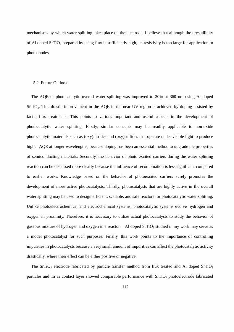
112
mechanisms by which water splitting takes place on the electrode. I believe that although the crystallinity
of Al doped SrTiO3 prepared by using flux is sufficiently high, its resistivity is too large for application to
photoanodes.
5.2. Future Outlook
The AQE of photocatalytic overall water splitting was improved to 30% at 360 nm using Al doped
SrTiO3. This drastic improvement in the AQE in the near UV region is achieved by doping assisted by
facile flux treatments. This points to various important and useful aspects in the development of
photocatalytic water splitting. Firstly, similar concepts may be readily applicable to non-oxide
photocatalytic materials such as (oxy)nitrides and (oxy)sulfides that operate under visible light to produce
higher AQE at longer wavelengths, because doping has been an essential method to upgrade the properties
of semiconducting materials. Secondly, the behavior of photo-excited carriers during the water splitting
reaction can be discussed more clearly because the influence of recombination is less significant compared
to earlier works. Knowledge based on the behavior of photoexcited carriers surely promotes the
development of more active photocatalysts. Thirdly, photocatalysts that are highly active in the overall
water splitting may be used to design efficient, scalable, and safe reactors for photocatalytic water splitting.
Unlike photoelectrochemical and electrochemical systems, photocatalytic systems evolve hydrogen and
oxygen in proximity. Therefore, it is necessary to utilize actual photocatalysts to study the behavior of
gaseous mixture of hydrogen and oxygen in a reactor. Al doped SrTiO3 studied in my work may serve as
a model photocatalyst for such purposes. Finally, this work points to the importance of controlling
impurities in photocatalysts because a very small amount of impurities can affect the photocatalytic activity
drastically, where their effect can be either positive or negative.
The SrTiO3 electrode fabricated by particle transfer method from flux treated and Al doped SrTiO3
particles and Ta as contact layer showed comparable performance with SrTiO3 photoelectrode fabricated

113
from single crystalline wafer of Nb doped SrTiO3. The SrTiO3 electrode fabricated by particle transfer
method showed relatively high IPCE of 69%, reflecting the possibility of particle based
photoelectrochemical cells efficient for sunlight driven water splitting. However, preparation of high
quality photocatalytic particles with absorption edge long enough to absorb visible light is still a challenge.
Through this study, I showed possibility of sunlight driven water splitting by photocatalysis and
photoelecrochemistry. Further development of photocatalytic materials which could utilize visible light, of
modification of the photocatalytic particles, and of cocatalysts to decrease overpotentials of water splitting
reactions will allow us to obtain hydrogen from water under sunlight with practical efficiency.
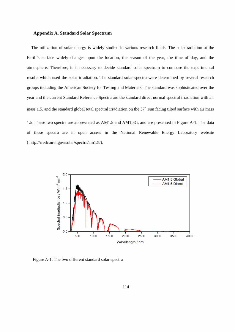
114
Appendix A. Standard Solar Spectrum
The utilization of solar energy is widely studied in various research fields. The solar radiation at the
Earth’s surface widely changes upon the location, the season of the year, the time of day, and the
atmosphere. Therefore, it is necessary to decide standard solar spectrum to compare the experimental
results which used the solar irradiation. The standard solar spectra were determined by several research
groups including the American Society for Testing and Materials. The standard was sophisticated over the
year and the current Standard Reference Spectra are the standard direct normal spectral irradiation with air
mass 1.5, and the standard global total spectral irradiation on the 37˚ sun facing tilted surface with air mass
1.5. These two spectra are abbreviated as AM1.5 and AM1.5G, and are presented in Figure A-1. The data
of these spectra are in open access in the National Renewable Energy Laboratory website
( http://rredc.nrel.gov/solar/spectra/am1.5/).
Figure A-1. The two different standard solar spectra
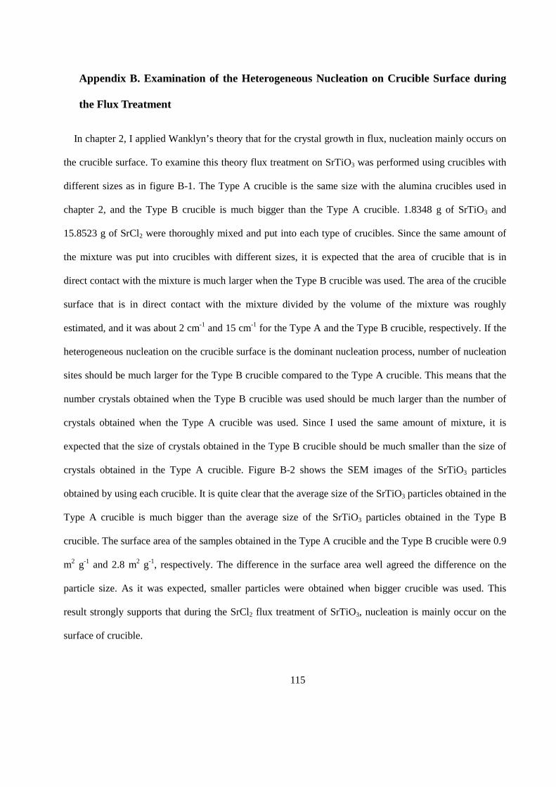
115
Appendix B. Examination of the Heterogeneous Nucleation on Crucible Surface during
the Flux Treatment
In chapter 2, I applied Wanklyn’s theory that for the crystal growth in flux, nucleation mainly occurs on
the crucible surface. To examine this theory flux treatment on SrTiO3 was performed using crucibles with
different sizes as in figure B-1. The Type A crucible is the same size with the alumina crucibles used in
chapter 2, and the Type B crucible is much bigger than the Type A crucible. 1.8348 g of SrTiO3 and
15.8523 g of SrCl2 were thoroughly mixed and put into each type of crucibles. Since the same amount of
the mixture was put into crucibles with different sizes, it is expected that the area of crucible that is in
direct contact with the mixture is much larger when the Type B crucible was used. The area of the crucible
surface that is in direct contact with the mixture divided by the volume of the mixture was roughly
estimated, and it was about 2 cm-1 and 15 cm-1 for the Type A and the Type B crucible, respectively. If the
heterogeneous nucleation on the crucible surface is the dominant nucleation process, number of nucleation
sites should be much larger for the Type B crucible compared to the Type A crucible. This means that the
number crystals obtained when the Type B crucible was used should be much larger than the number of
crystals obtained when the Type A crucible was used. Since I used the same amount of mixture, it is
expected that the size of crystals obtained in the Type B crucible should be much smaller than the size of
crystals obtained in the Type A crucible. Figure B-2 shows the SEM images of the SrTiO3 particles
obtained by using each crucible. It is quite clear that the average size of the SrTiO3 particles obtained in the
Type A crucible is much bigger than the average size of the SrTiO3 particles obtained in the Type B
crucible. The surface area of the samples obtained in the Type A crucible and the Type B crucible were 0.9
m2 g-1 and 2.8 m2 g-1, respectively. The difference in the surface area well agreed the difference on the
particle size. As it was expected, smaller particles were obtained when bigger crucible was used. This
result strongly supports that during the SrCl2 flux treatment of SrTiO3, nucleation is mainly occur on the
surface of crucible.
116
Figure B-1. The Type A crucible and the Type B crucible used for the flux treatment.
Figure B-2. The SEM images of flux treated SrTiO3 (a) in Type A crucible and (b) in the Type B
crucible.
117
List of Publication
1. Yeilin Ham, Takashi Hisatomi, Yosuke Goto, Yosuke Moriya, Yoshihisa Sakata, Akira Yamakata,
Jun Kubota, Kazunari Domen, “Flux-Mediated Doping of SrTiO3 Photocatalysts for Efficient Overall
Water Splitting”, Journal of Materials Chemistry A, accepted.
2. Yoshihisa Sakata, Yoshiko Miyoshi, Tatsuya Maeda, Kohki Ishikiriyama, Yuki Yamazaki, Hayao
Imamura, Yeilin Ham, Takashi Hisatomi, Jun Kubota, Akira Yamakata, Kazunari Domen, “Photocatalytic
Property of Metal ion Added SrTiO3 to the Overall H2O Splitting”, Applied Catalysis: A General,
accepted.
3. Akira Yamakata, Yeilin Ham, Masayuki Kawaguchi, Takashi Hisatomi, Jun Kubota, Yoshihisa
Sakata, Kazunari Domen, “Morphology-Sensitive Trapping States of Photogenerated Charge Carriers on
SrTiO3 Particles Studied by Time-Resolved Visible to Mid-IR Absorption Spectroscopy: The Effects of
Molten Salt Flux Treatments”, Journal of Photochemistry and Photobiology A: Chemistry, in press.
4. Yeilin Ham, Minegishi Tsutomu, Takashi Hisatomi, Kazunari Domen, “SrTiO3 Photoanode
Prepared by Particle Transfer Method for Oxygen Evolution from Water with High Quantum Efficiencies”,
Chemical Communications, submitted.
5. Yeilin Ham, Kazuhiko Maeda, Dongkyu Cha, Kazuhiro Takanabe, Kazunari Domen, “Synthesis
and Photocatalytic Activity of Poly(triazine imide)”, Chemistry – an Asian Journal, 8 (1), 2013, 218-224.
6. Jang Mee Lee, Jayavant L. Gunjakar, Yeilin Ham, In Young Kim, Kazunari Domen, Seong-Ju
Hwang, “A Linker-Mediated Self-Assembly Method to Couple Isocharged Nanostructures: Layered
Double Hydroxide—CdS Nanohybrids with High Activity for Visible-Light-Induced H2 Generation”,
Chemistry — a European Journal, 20 (51), 2014, 17004-17010.

118
Acknowledgments
I want to express my deep gratitude to Professor Kazunari Domen. I do not think there is a way that I
could pay back what you have given me. You gave me another change, and I hope you do not regret that
decision. Your attitude toward the research and toward colleagues was what I most wanted to learn from
you. It was my blessing that I could come to your laboratory.
Professors I met in Domen laboratory were all really brilliant people. I discussion with Professor Jun
Kubota, Professor Kazuhiko Maeda, Professor Kazuhiro Takanabe, Professor Tsutomu Minegishi and
Professor Masao Katayama were very kind and their ideas were always helpful for my research.
Also, I am obliged to Dr. Takashi Hisatomi, Dr. Yosuke Moriya, Professor Yoshihisa Sakata and
Professor Akira Yamakata. This thesis was never finished with the help from them.
Ms. Tomita and Ms. Minegishi were the most nicest, kind people, and time to time small talk with them
was a few happy entertainment I had in our lab.
Also, I need to thank Professor Takayuki Komatsu. I always tough of him as my father, and I hope to do
so as long as he allow me to do so.
My family is probably why I am working at all. I am very blessed to have my family Woonchul Ham,
Inja Kim and Hyeilin Ham. Hyeilin’s advice to me for writing doctoral thesis was what I rely on the most.
I was also supported by my dearest friend Bosul Jeon, and my kind Doctor Takei.
Thomas Kuhn’s book let me understand a lot about this field more than anyone else. While doing these
experiments I always struggled with the lack of theorems and even hypothesis or premises. This book let
me understand that situation. Now I understand that the field of photocatalytic water splitting is only on the
stage of normal science and the lack of theorem is a natural state of the normal science. This realization let
me work harder so that I could contribute for this field to move forward to be a new paradigm.
I own thanks to Rainer Maria Rilke, Arthur Schopenhauer, Herman Hesse, Patrick Suskind and many
other great teachers who taught me how to live, and gave me the strength to finish this thesis. The fact that
people like them existed, people who care about human being exists itself was a great relief for me.

119
Last but not least, I want to express my gracefulness to hyde. The truth is, so long as I can breathe or my
eyes can see, every work I do should be dedicated to him.
Related Documents