Photocatalysis & its application in water treatment Department of Chemical Engineering Government Engineering College Thrissur 1 INTRODUCTION Reaction Engineering basically deals with the use to the kinetic data of a chemical reaction which is obtained through experiments to design a reactor, ie; to calculate the volume required for a particular degree of conversion to take place. Reaction kinetics is the study of dependence of the rate of reaction on temperature and concentration (pressure for gases) of various components involved in the reaction. The equation that gives such a relationship is called the rate law. For eg; for A → PRODUCTS − = ∗ ( ) …. (i) k, called rate constant is the temperature dependent term. f(C A ) is the concentration dependent term. If the reaction takes place in presence of a catalyst, Catalyst A PRODUCTS and C C is the concentration of catalyst at time t, − = ∗ ( )∗ ( ) …(ii) A catalyst speeds up a reaction. It takes the reaction through a path having lower activation energy (E g ). Its concentration has an effect on the rate since, higher the concentration, the more the number of active pores on which the reaction takes place. In certain cases, the activity of the catalyst may be low. In such cases, the need for an agent that can enhance the activity of catalyst may be employed. Such an agent is called a promoter. Another agent that can be conveniently used for this purpose is light energy. Temperature dependent term As mentioned above, the temperature dependent term is k and through experiments, we have proven that, ‘k’ varies with temperature as: = ∗ (− / ) …(iii)

Welcome message from author
This document is posted to help you gain knowledge. Please leave a comment to let me know what you think about it! Share it to your friends and learn new things together.
Transcript
Photocatalysis & its application in water treatment
Department of Chemical EngineeringGovernment Engineering College Thrissur
1
INTRODUCTION
Reaction Engineering basically deals with the use to the kinetic data of a chemicalreaction which is obtained through experiments to design a reactor, ie; to calculate thevolume required for a particular degree of conversion to take place.
Reaction kinetics is the study of dependence of the rate of reaction on temperatureand concentration (pressure for gases) of various components involved in thereaction. The equation that gives such a relationship is called the rate law.
For eg; for A → PRODUCTS− = ∗ ( ) …. (i)
k, called rate constant is the temperature dependent term.
f(CA) is the concentration dependent term.
If the reaction takes place in presence of a catalyst,
CatalystA PRODUCTS
and CC is the concentration of catalyst at time t,− = ∗ ( ) ∗ ( ) …(ii)
A catalyst speeds up a reaction. It takes the reaction through a path having loweractivation energy (Eg). Its concentration has an effect on the rate since, higher theconcentration, the more the number of active pores on which the reaction takes place.
In certain cases, the activity of the catalyst may be low. In such cases, the need for anagent that can enhance the activity of catalyst may be employed. Such an agent iscalled a promoter. Another agent that can be conveniently used for this purpose islight energy.
Temperature dependent term
As mentioned above, the temperature dependent term is k and through experiments,we have proven that, ‘k’ varies with temperature as:= ∗ (− / ) …(iii)
Photocatalysis & its application in water treatment
Department of Chemical EngineeringGovernment Engineering College Thrissur
2
where ko is the frequency factor, Ea is the energy of activation, R is the universal gasconstant and T, the absolute temperature.
Concentration dependent term
The term f(CA) = CAn where ‘n’ is known as the order of the reaction which is
determined experimentally.
Nature of general solid catalyzed reactions
The selection of a catalyst to promote a reaction is not well understood;therefore, in practice extensive trial and error may be needed to produce asatisfactory catalyst.Duplication of the chemical constitution of a good catalyst is no guarantee thatthe solid produced will have any catalytic activity. This observation suggeststhat it is the physical or crystalline structure which somehow imparts catalyticactivity to a material. This view is strengthened by the fact that heating acatalyst above a certain critical temperature may cause it to lose its activity,often permanently. Thus present research on catalysts is strongly centered onthe surface structure of solids.To explain the action of catalysts, it is thought that reactant molecules aresomehow changed, energized, or affected to form intermediates in the regionsclose to the catalyst surface. Various theories have been proposed to explainthe details of this action. In one theory, the intermediate is viewed as anassociation of a reactant molecule with a region of the surface; in other words,the molecules are somehow attached to the surface. In another theory,molecules are thought to move down into the atmosphere close to the surfaceand be under the influence of surface forces. In this view the molecules arestill mobile but are nevertheless modified. In still a third theory, it is thoughtthat an active complex, a free radical, is formed at the surface of the catalyst.This free radical then moves back into the main gas stream, triggering a chainof reactions with fresh molecules before being finally destroyed. In contrastwith the first two theories, which consider the reaction to occur in the vicinityof the surface, this theory views the catalyst surface simply as a generator offree radicals, with the reaction occurring in the main body of the gas.In terms of the transition-state theory, the catalyst reduces the potential energybarrier over which the reactants must pass to form products.Though a catalyst may speed up a reaction, it never determines theequilibrium or endpoint of a reaction. This is governed by thermodynamicsalone. Thus with or without a catalyst the equilibrium constant for the reactionis always the same.[1]

Photocatalysis & its application in water treatment
Department of Chemical EngineeringGovernment Engineering College Thrissur
3
Complications in the rate equation in presence of a catalyst
In a heterogeneous catalytic reaction, since more than one phase is present, themovement of material from phase to phase must be considered in the rate equation.Thus the rate expression in general will incorporate mass transfer terms in addition tothe usual chemical kinetics term. These mass transfer terms are different in type andnumbers in the different kinds of heterogeneous systems; hence, no single rateexpression has general application.
Photocatalysis & its application in water treatment
Department of Chemical EngineeringGovernment Engineering College Thrissur
4
OVERVIEW OF PHOTOCATALYSIS
Photo catalysts are far distant in their nature from conventional solid catalysts. Themost important characteristic of them is that they do not contain active sites. Hence,photocatalytic reactions have entirely different mechanisms.
This important feature of photocatalytic reactions plays an important role in theirkinetic equations. Unlike conventional heterogeneous catalytic reactions,photocatalytic reactions have simple rate equations. Hence, a lot of investment to findout the mechanism of reactions could be saved in case of photocatalytic reactions.
Rate Law − = /( + ) ….(iv)
Where , , , , are incident light flux, photo absorption efficiency, rateconstant of reaction of electron-hole pairs with surface absorbed substrate, surfaceconcentration of reaction substrate, and rate constant of electron-hole recombinationrespectively.[2]
Here, the rate equation is analyzed to extract intrinsic parameters, i.e., only thosedepending on the photocatalyst. The intensity I is an extrinsic (experimental) factorand the photoabsorption coefficient is an intrinsic parameter depending on thephotocatalyst and irradiation wavelength.
Quantum efficiency is the ratio of reaction rate and absorbed photon flux, . Sincequantum efficiency, = , in an ordinary photocatalytic reaction system has beenreported to be much lower than unity, it is assumed that << .Consequently, equation is further simplified to be :− = / ….(v)
In this equation, the terms , , can be measured or estimated by photometry,spectrophotometry, and absorption analysis, respectively. Therefore, the ratio/ can be extracted from the actual rate. Considering that this ratio does notcontain factors or parameters that depend on the reaction conditions, the ratio /or its product with may be one of the possible measures of intrinsic photocatalyticactivity. Assuming further that, the rate constant of electron-hole pair reaction, isnot changed in a series of photocatalytic samples, the ratio can be a relative measureof rate constant for electron-hole recombination[2].
Photocatalysis & its application in water treatment
Department of Chemical EngineeringGovernment Engineering College Thrissur
5
Study of dependence of various parameters on rate: Degradation ofphenol
, = , ∗ ( ) ∗ ( )Where , is the initial rate with respect to species i, , its initial concentration,
the photocatalyst concentration, and the intensity of incident photons.
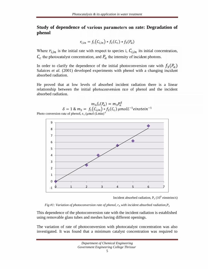
In order to clarify the dependence of the initial photoconversion rate with ( )Salaices et al. (2001) developed experiments with phenol with a changing incidentabsorbed radiation.
He proved that at low levels of absorbed incident radiation there is a linearrelationship between the initial photoconversion rate of phenol and the incidentabsorbed radiation. ( ) == 1 & = , ∗ ( )Photo conversion rate of phenol, rA (μmol (Lmin)-1
Incident absorbed radiation, Pa (106 einsteins/s)
Fig #1: Variation of photoconversion rate of phenol, rA with incident absorbed radiation,Pa
This dependence of the photoconversion rate with the incident radiation is establishedusing removable glass tubes and meshes having different openings.
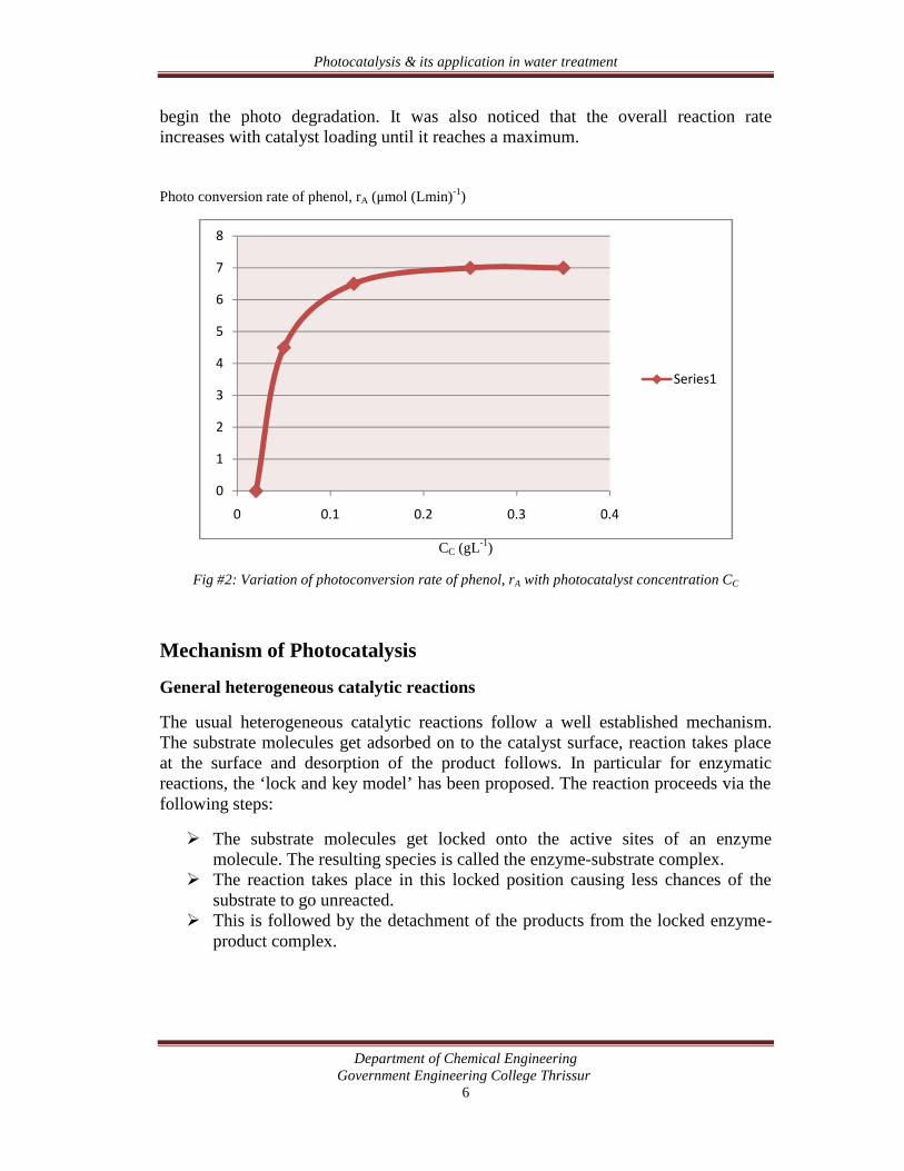
The variation of rate of photoconversion with photocatalyst concentration was alsoinvestigated. It was found that a minimum catalyst concentration was required to
-1
0
1
2
3
4
5
6
7
8
9
0 1 2 3 4 5 6 7
Photocatalysis & its application in water treatment
Department of Chemical EngineeringGovernment Engineering College Thrissur
6
begin the photo degradation. It was also noticed that the overall reaction rateincreases with catalyst loading until it reaches a maximum.
Photo conversion rate of phenol, rA (μmol (Lmin)-1)
CC (gL-1)
Fig #2: Variation of photoconversion rate of phenol, rA with photocatalyst concentration CC
Mechanism of Photocatalysis
General heterogeneous catalytic reactions
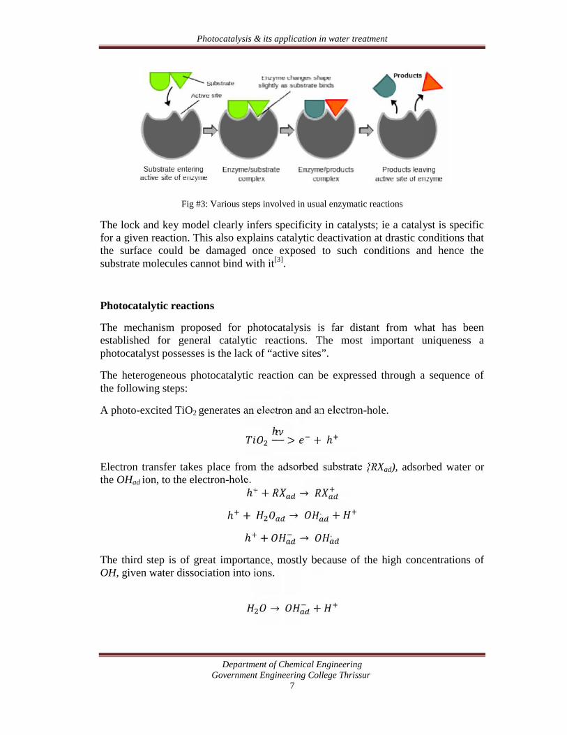
The usual heterogeneous catalytic reactions follow a well established mechanism.The substrate molecules get adsorbed on to the catalyst surface, reaction takes placeat the surface and desorption of the product follows. In particular for enzymaticreactions, the ‘lock and key model’ has been proposed. The reaction proceeds via thefollowing steps:
The substrate molecules get locked onto the active sites of an enzymemolecule. The resulting species is called the enzyme-substrate complex.
The reaction takes place in this locked position causing less chances of thesubstrate to go unreacted.
This is followed by the detachment of the products from the locked enzyme-product complex.
0
1
2
3
4
5
6
7
8
0 0.1 0.2 0.3 0.4
Series1
Photocatalysis & its application in water treatment
Department of Chemical EngineeringGovernment Engineering College Thrissur
7
Fig #3: Various steps involved in usual enzymatic reactions
The lock and key model clearly infers specificity in catalysts; ie a catalyst is specificfor a given reaction. This also explains catalytic deactivation at drastic conditions thatthe surface could be damaged once exposed to such conditions and hence thesubstrate molecules cannot bind with it[3].
Photocatalytic reactions
The mechanism proposed for photocatalysis is far distant from what has beenestablished for general catalytic reactions. The most important uniqueness aphotocatalyst possesses is the lack of “active sites”.
The heterogeneous photocatalytic reaction can be expressed through a sequence ofthe following steps:
A photo-excited TiO2 generates an electron and an electron-hole.ℎ > + ℎElectron transfer takes place from the adsorbed substrate {RXad), adsorbed water orthe OHad ion, to the electron-hole.ℎ + →ℎ + → . +ℎ + → .The third step is of great importance, mostly because of the high concentrations ofOH, given water dissociation into ions.
→ +
Photocatalysis & its application in water treatment
Department of Chemical EngineeringGovernment Engineering College Thrissur
8
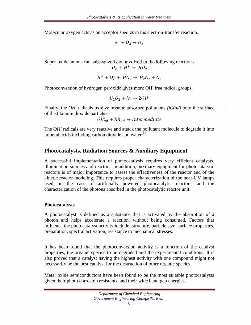
Molecular oxygen acts as an acceptor species in the electron-transfer reaction.+ →Super-oxide anions can subsequently be involved in the following reactions.+ → .+ + . → +Photoconversion of hydrogen peroxide gives more OH. free radical groups.+ ℎ → 2 .Finally, the OH. radicals oxidize organic adsorbed pollutants (RXad) onto the surfaceof the titanium dioxide particles.. + →The OH' radicals are very reactive and attack the pollutant molecule to degrade it intomineral acids including carbon dioxide and water[4].
Photocatalysts, Radiation Sources & Auxiliary Equipment
A successful implementation of photocatalysis requires very efficient catalysts,illumination sources and reactors. In addition, auxiliary equipment for photocatalyticreactors is of major importance to assess the effectiveness of the reactor and of thekinetic reactor modeling. This requires proper characterization of the near-UV lampsused, in the case of artificially powered photocatalytic reactors, and thecharacterization of the photons absorbed in the photocatalytic reactor unit.
Photocatalysts
A photocatalyst is defined as a substance that is activated by the absorption of aphoton and helps accelerate a reaction, without being consumed. Factors thatinfluence the photocatalyst activity include: structure, particle size, surface properties,preparation, spectral activation, resistance to mechanical stresses.
It has been found that the photoconversion activity is a function of the catalystproperties, the organic species to be degraded and the experimental conditions. It isalso proved that a catalyst having the highest activity with one compound might notnecessarily be the best catalyst for the destruction of other organic species.
Metal oxide semiconductors have been found to be the most suitable photocatalystsgiven their photo corrosion resistance and their wide band gap energies.
Photocatalysis & its application in water treatment
Department of Chemical EngineeringGovernment Engineering College Thrissur
9
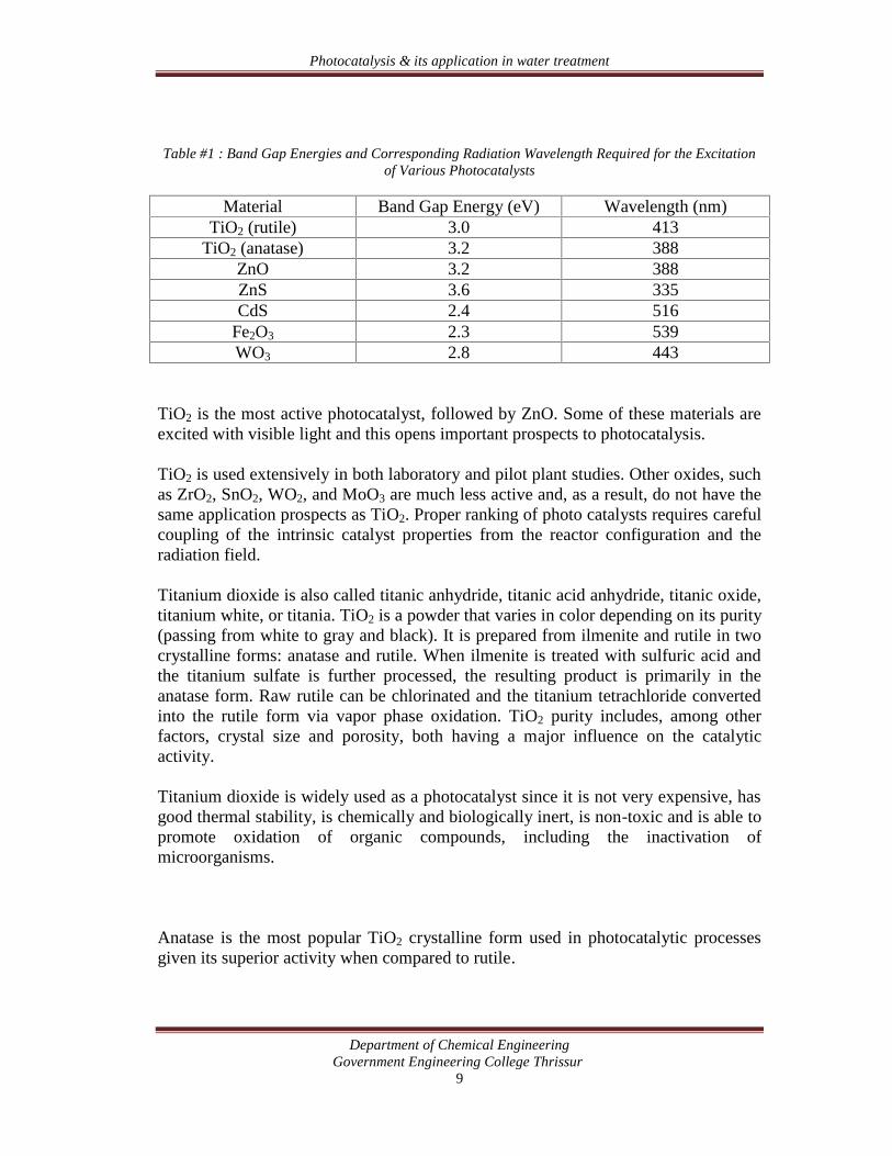
Table #1 : Band Gap Energies and Corresponding Radiation Wavelength Required for the Excitationof Various Photocatalysts
Material Band Gap Energy (eV) Wavelength (nm)TiO2 (rutile) 3.0 413
TiO2 (anatase) 3.2 388ZnO 3.2 388ZnS 3.6 335CdS 2.4 516
Fe2O3 2.3 539WO3 2.8 443
TiO2 is the most active photocatalyst, followed by ZnO. Some of these materials areexcited with visible light and this opens important prospects to photocatalysis.
TiO2 is used extensively in both laboratory and pilot plant studies. Other oxides, suchas ZrO2, SnO2, WO2, and MoO3 are much less active and, as a result, do not have thesame application prospects as TiO2. Proper ranking of photo catalysts requires carefulcoupling of the intrinsic catalyst properties from the reactor configuration and theradiation field.
Titanium dioxide is also called titanic anhydride, titanic acid anhydride, titanic oxide,titanium white, or titania. TiO2 is a powder that varies in color depending on its purity(passing from white to gray and black). It is prepared from ilmenite and rutile in twocrystalline forms: anatase and rutile. When ilmenite is treated with sulfuric acid andthe titanium sulfate is further processed, the resulting product is primarily in theanatase form. Raw rutile can be chlorinated and the titanium tetrachloride convertedinto the rutile form via vapor phase oxidation. TiO2 purity includes, among otherfactors, crystal size and porosity, both having a major influence on the catalyticactivity.
Titanium dioxide is widely used as a photocatalyst since it is not very expensive, hasgood thermal stability, is chemically and biologically inert, is non-toxic and is able topromote oxidation of organic compounds, including the inactivation ofmicroorganisms.
Anatase is the most popular TiO2 crystalline form used in photocatalytic processesgiven its superior activity when compared to rutile.
Photocatalysis & its application in water treatment
Department of Chemical EngineeringGovernment Engineering College Thrissur
10
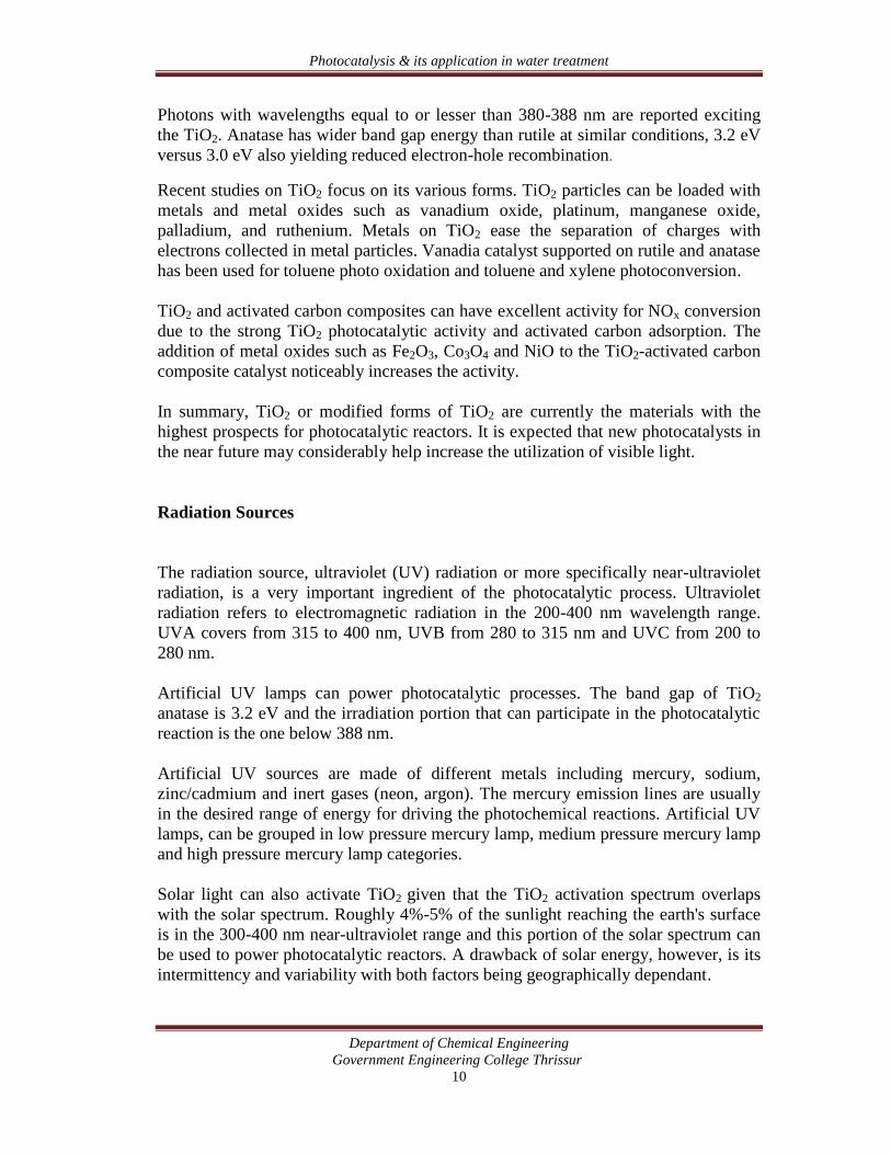
Photons with wavelengths equal to or lesser than 380-388 nm are reported excitingthe TiO2. Anatase has wider band gap energy than rutile at similar conditions, 3.2 eVversus 3.0 eV also yielding reduced electron-hole recombination.
Recent studies on TiO2 focus on its various forms. TiO2 particles can be loaded withmetals and metal oxides such as vanadium oxide, platinum, manganese oxide,palladium, and ruthenium. Metals on TiO2 ease the separation of charges withelectrons collected in metal particles. Vanadia catalyst supported on rutile and anatasehas been used for toluene photo oxidation and toluene and xylene photoconversion.
TiO2 and activated carbon composites can have excellent activity for NOx conversiondue to the strong TiO2 photocatalytic activity and activated carbon adsorption. Theaddition of metal oxides such as Fe2O3, Co3O4 and NiO to the TiO2-activated carboncomposite catalyst noticeably increases the activity.
In summary, TiO2 or modified forms of TiO2 are currently the materials with thehighest prospects for photocatalytic reactors. It is expected that new photocatalysts inthe near future may considerably help increase the utilization of visible light.
Radiation Sources
The radiation source, ultraviolet (UV) radiation or more specifically near-ultravioletradiation, is a very important ingredient of the photocatalytic process. Ultravioletradiation refers to electromagnetic radiation in the 200-400 nm wavelength range.UVA covers from 315 to 400 nm, UVB from 280 to 315 nm and UVC from 200 to280 nm.
Artificial UV lamps can power photocatalytic processes. The band gap of TiO2
anatase is 3.2 eV and the irradiation portion that can participate in the photocatalyticreaction is the one below 388 nm.
Artificial UV sources are made of different metals including mercury, sodium,zinc/cadmium and inert gases (neon, argon). The mercury emission lines are usuallyin the desired range of energy for driving the photochemical reactions. Artificial UVlamps, can be grouped in low pressure mercury lamp, medium pressure mercury lampand high pressure mercury lamp categories.
Solar light can also activate TiO2 given that the TiO2 activation spectrum overlapswith the solar spectrum. Roughly 4%-5% of the sunlight reaching the earth's surfaceis in the 300-400 nm near-ultraviolet range and this portion of the solar spectrum canbe used to power photocatalytic reactors. A drawback of solar energy, however, is itsintermittency and variability with both factors being geographically dependant.
Photocatalysis & its application in water treatment
Department of Chemical EngineeringGovernment Engineering College Thrissur
11
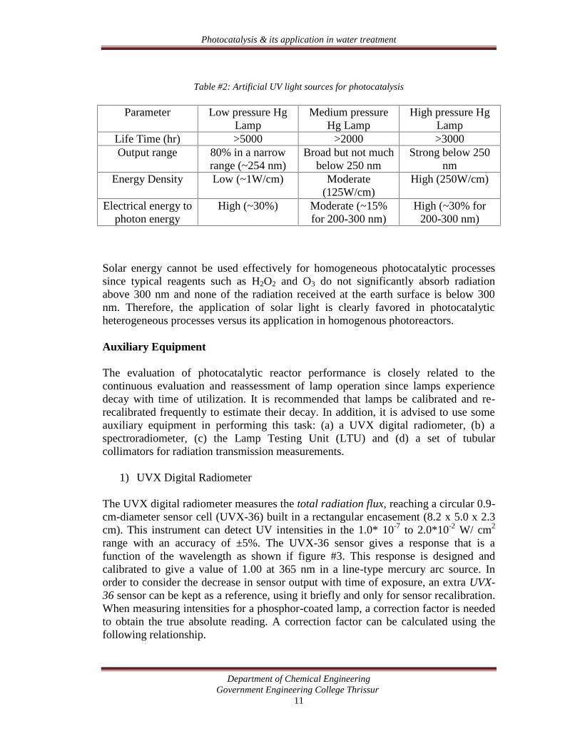
Table #2: Artificial UV light sources for photocatalysis
Parameter Low pressure HgLamp
Medium pressureHg Lamp
High pressure HgLamp
Life Time (hr) >5000 >2000 >3000Output range 80% in a narrow
range (~254 nm)Broad but not much
below 250 nmStrong below 250
nmEnergy Density Low (~1W/cm) Moderate
(125W/cm)High (250W/cm)
Electrical energy tophoton energy
High (~30%) Moderate (~15%for 200-300 nm)
High (~30% for200-300 nm)
Solar energy cannot be used effectively for homogeneous photocatalytic processessince typical reagents such as H2O2 and O3 do not significantly absorb radiationabove 300 nm and none of the radiation received at the earth surface is below 300nm. Therefore, the application of solar light is clearly favored in photocatalyticheterogeneous processes versus its application in homogenous photoreactors.
Auxiliary Equipment
The evaluation of photocatalytic reactor performance is closely related to thecontinuous evaluation and reassessment of lamp operation since lamps experiencedecay with time of utilization. It is recommended that lamps be calibrated and re-recalibrated frequently to estimate their decay. In addition, it is advised to use someauxiliary equipment in performing this task: (a) a UVX digital radiometer, (b) aspectroradiometer, (c) the Lamp Testing Unit (LTU) and (d) a set of tubularcollimators for radiation transmission measurements.
1) UVX Digital Radiometer
The UVX digital radiometer measures the total radiation flux, reaching a circular 0.9-cm-diameter sensor cell (UVX-36) built in a rectangular encasement (8.2 x 5.0 x 2.3cm). This instrument can detect UV intensities in the 1.0* 10-7 to 2.0*10-2 W/ cm2
range with an accuracy of ±5%. The UVX-36 sensor gives a response that is afunction of the wavelength as shown if figure #3. This response is designed andcalibrated to give a value of 1.00 at 365 nm in a line-type mercury arc source. Inorder to consider the decrease in sensor output with time of exposure, an extra UVX-36 sensor can be kept as a reference, using it briefly and only for sensor recalibration.When measuring intensities for a phosphor-coated lamp, a correction factor is neededto obtain the true absolute reading. A correction factor can be calculated using thefollowing relationship.
Photocatalysis & its application in water treatment
Department of Chemical EngineeringGovernment Engineering College Thrissur
12
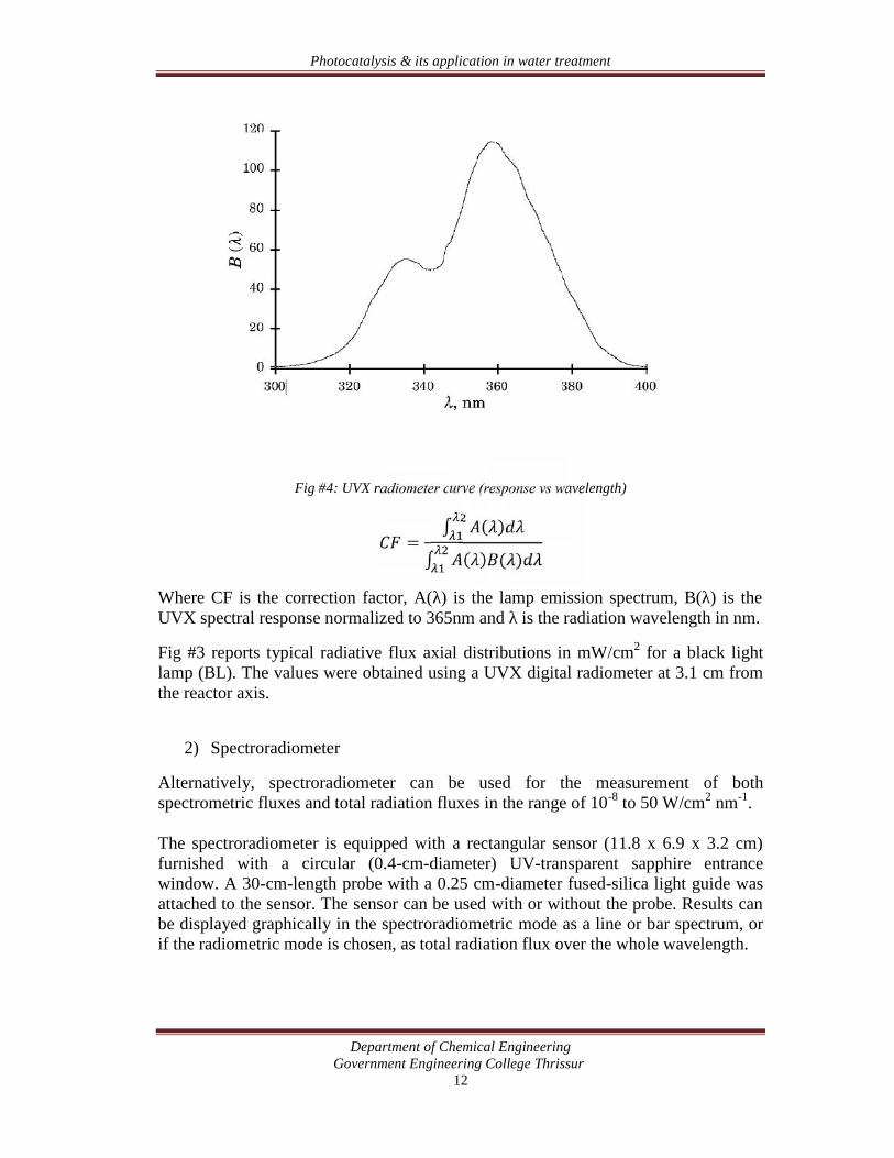
Fig #4: UVX radiometer curve (response vs wavelength)
= ∫ ( )∫ ( ) ( )Where CF is the correction factor, A(λ) is the lamp emission spectrum, B(λ) is theUVX spectral response normalized to 365nm and λ is the radiation wavelength in nm.
Fig #3 reports typical radiative flux axial distributions in mW/cm2 for a black lightlamp (BL). The values were obtained using a UVX digital radiometer at 3.1 cm fromthe reactor axis.
2) Spectroradiometer
Alternatively, spectroradiometer can be used for the measurement of bothspectrometric fluxes and total radiation fluxes in the range of 10-8 to 50 W/cm2 nm-1.
The spectroradiometer is equipped with a rectangular sensor (11.8 x 6.9 x 3.2 cm)furnished with a circular (0.4-cm-diameter) UV-transparent sapphire entrancewindow. A 30-cm-length probe with a 0.25 cm-diameter fused-silica light guide wasattached to the sensor. The sensor can be used with or without the probe. Results canbe displayed graphically in the spectroradiometric mode as a line or bar spectrum, orif the radiometric mode is chosen, as total radiation flux over the whole wavelength.
Photocatalysis & its application in water treatment
Department of Chemical EngineeringGovernment Engineering College Thrissur
13
3) Lamp testing unit
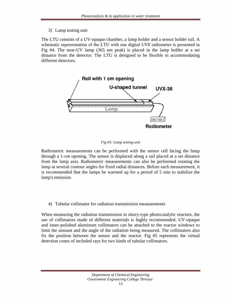
The LTU consists of a UV-opaque chamber, a lamp holder and a sensor holder rail. Aschematic representation of the LTU with one digital UVX radiometer is presented inFig #4. The near-UV lamp (365 nm peak) is placed in the lamp holder at a setdistance from the detector. The LTU is designed to be flexible in accommodatingdifferent detectors.
Fig #5: Lamp testing unit
Radiometric measurements can be performed with the sensor cell facing the lampthrough a 1-cm opening. The sensor is displaced along a rail placed at a set distancefrom the lamp axis. Radiometric measurements can also be performed rotating thelamp at several contour angles for fixed radial distances. Before each measurement, itis recommended that the lamps be warmed up for a period of 5 min to stabilize thelamp's emission.
4) Tubular collimator for radiation transmission measurements
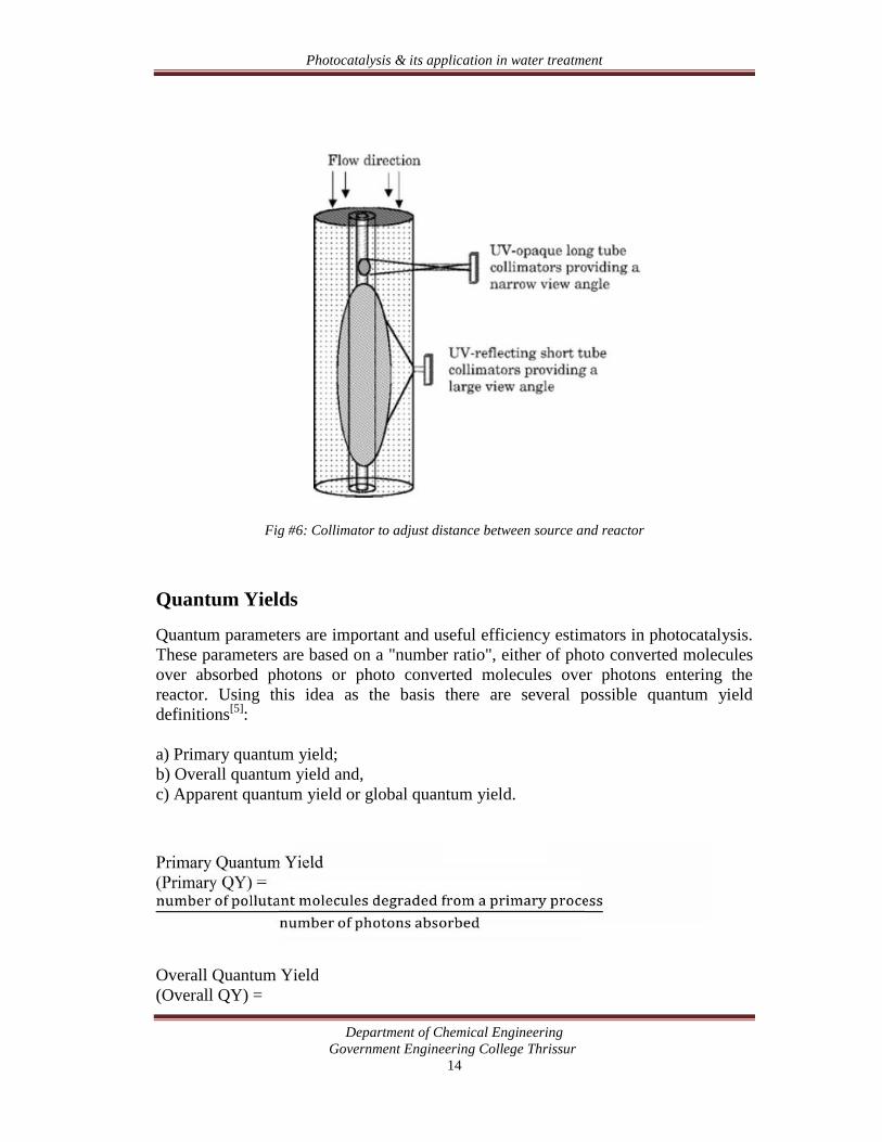
When measuring the radiation transmission in slurry-type photocatalytic reactors, theuse of collimators made of different materials is highly recommended. UV-opaqueand inner-polished aluminum collimators can be attached to the reactor windows tolimit the amount and the angle of the radiation being measured. The collimators alsofix the position between the sensor and the reactor. Fig #5 represents the virtualdetection cones of included rays for two kinds of tubular collimators.
Photocatalysis & its application in water treatment
Department of Chemical EngineeringGovernment Engineering College Thrissur
14
Fig #6: Collimator to adjust distance between source and reactor
Quantum Yields
Quantum parameters are important and useful efficiency estimators in photocatalysis.These parameters are based on a "number ratio", either of photo converted moleculesover absorbed photons or photo converted molecules over photons entering thereactor. Using this idea as the basis there are several possible quantum yielddefinitions[5]:
a) Primary quantum yield;b) Overall quantum yield and,c) Apparent quantum yield or global quantum yield.
Primary Quantum Yield(Primary QY) =
Overall Quantum Yield(Overall QY) =

Photocatalysis & its application in water treatment
Department of Chemical EngineeringGovernment Engineering College Thrissur
15
Apparent Quantum Yield
(Apparent QY), φ =
Photocatalysis & its application in water treatment
Department of Chemical EngineeringGovernment Engineering College Thrissur
16
APPLICATION OF PHOTOCATALYSIS IN WATERTREATMENT
Heterogeneous photocatalysis is a rapidly expanding technology for water and airtreatment. The initial interest in the heterogeneous photocatalysis was started whenFujishima and Honda discovered in 1972 the photochemical splitting of water intohydrogen and oxygen with TiO2. From this date extensive work has been carried outto produce hydrogen from water by this novel oxidation reduction reaction using avariety of semiconductors.
In recent years interest has been focused on the use of semiconductor materials asphotocatalysts for the removal of organic and inorganic species from aqueous or gasphase. This method has been suggested in environmental protection due to its abilityto oxidize the organic and inorganic substrates.
Heterogeneous photocatalysis using semiconductors such as titanium dioxide can bemore interesting than conventional methods for removing organic species in theenvironment. Because the process gradually breaks down the contaminant molecule,no residue of the original material remains and therefore no sludge requiring disposalto landfill is produced. The catalyst itself is unchanged during the process and noconsumable chemicals are required. This results in considerable savings and a simpleroperation of the equipment involved. Additionally, because the contaminant isattracted strongly to the surface of the catalyst, the process will continue to work atvery low concentrations allowing sub part-per-million consents to be achieved. Takentogether, these advantages mean that the process results in considerable savings in thewater production cost and keeping the environment clean.
The electron and hole can recombine, releasing the absorbed light energy as heat,with no chemical effect. Otherwise, the charges can move to "trap" sites at slightlylower energies. The charges can still recombine, or they participate in redox reactionswith adsorbed species. The valence band hole is strongly oxidizing, and theconduction band electron is strongly reducing. At the external surface, the excitedelectron and the hole can take part in redox reactions with adsorbed species such aswater, hydroxide ion (OH-), organic compounds, or oxygen. The charges can reactdirectly with adsorbed pollutants, but reactions with water are far more likely sincethe water molecules are far more populous than contaminant molecules. Oxidation ofwater or OH- by the hole produces the hydroxyl radical (OH.), an extremely powerfuland indiscriminant oxidant. OH radicals rapidly attack pollutants at the surface, andpossibly in solution as well, and are usually the most important radicals formed inTiO2 photocatalysis. An important reaction of the conduction band electron isreduction of adsorbed O2 to O2
-. This both prevents the electron from recombining
Photocatalysis & its application in water treatment
Department of Chemical EngineeringGovernment Engineering College Thrissur
17
with the hole and results in an accumulation of oxygen radical species that can alsoparticipate in attacking contaminants.[6]
Photocatalytic reactors for water treatment
There is general agreement that an important obstacle in the development of highlyefficient photocatalytic reactors is the establishment of effective reactor designs forintermediate and large-scale use, as demanded by industrial and commercialapplications. To achieve a successful commercial implementation, several reactordesign parameters must be optimized, such as the photoreactor geometry, the type ofphotocatalyst and the utilization of radiated energy. A fundamental issue regardingthe successful implementation of photocatalytic reactors is the transmission ofirradiation in a highly scattering and absorbing medium composed of water and fineTiO2 particles.
The evaluation of irradiation and its distribution inside photocatalytic reactors isessential for the extrapolation of laboratory scale results to large-scale operations andthe comparison of the efficiencies of different installations. The successful scaling-upof photocatalytic reactors involves increasing the number of photons absorbed perunit time and per unit volume as well as efficiently using the electron holes createdduring the photocatalytic transformations.
While some of the physico-chemical principles of photocatalysis are relatively wellunderstood, reactor design and reactor engineering of photocatalytic units still requireconsideration. This is particularly true in the context of scaled reactors processinglarge volumes of water and using high levels of irradiation.
Several aspects of design optimization and operation of photochemical reactors thatare not usually considered in the design of conventional chemical reactors, should betaken into account. Some of these aspects are:
The selection of radiation sources including output power, source efficiency,spectral distribution, shape, dimensions, maintenance and operatingrequirements (warm up and cooling periods).
The design of reactor geometry with respect to the irradiation source.
The design of reactor irradiation devices including mirrors, reflectors andwindows, their construction materials, shape, dimensions and cleaningprocedures.
Photocatalysis & its application in water treatment
Department of Chemical EngineeringGovernment Engineering College Thrissur
18
Photocatalytic reactors for water treatment can be classified according to their designcharacteristics.
State of the photocatalyst: The photocatalyst can be either suspended or attached toa support:
Photocatalytic slurry reactors Photocatalytic reactors with immobilized photocatalyst
In slurry reactors, the catalyst particles are freely dispersed in the fluid phase (water)and consequently, the photocatalyst is fully integrated in the liquid mobile phase. Theimmobilized catalyst reactor design features a catalyst anchored to a fixed support,dispersed on the stationary phase (the catalyst support system).
Type of illumination: The type of irradiation is a major design issue forphotocatalytic reactors. Reactors can be irradiated using:
UV polychromatic lamps Solar light
Two subcategories branch off from solar illuminated reactors: non-concentratingreactors and concentrating reactors. Non-concentrating solar irradiated reactorsemploy intensities equal or lesser than natural solar irradiation while concentratingsolar reactors use irradiation intensities that surpass irradiations equivalent to one sun.
Position of the irradiation source: The position of the lamp or source of irradiationis a distinguishing feature of a photocatalytic reactor. The lamp position determinesdifferent configurations:
Reactors with an immersed light source Reactors with an external light source Reactors with distributed light sources
In immersed source reactors, the lamp is placed inside the unit. External sourcephotocatalytic reactors have lamps located outside the reactor vessel. In distributedreactors, irradiation is transported from the source to the reactor by optical meanssuch as reflectors or light guides.
Photocatalysis & its application in water treatment
Department of Chemical EngineeringGovernment Engineering College Thrissur
19
TiO2 Slurry Reactors
The majority of the photocatalytic reactors currently in use for water treatments are ofthe well-mixed slurry variety. Slurry systems have shown the largest photocatalyticactivity when compared to photocatalytic reactors with immobilized photocatalyst.
In a comparative study of the photo degradation of aqueous phenol using naturalsunlight and a reactor geometry simulating shallow ponds, the free photocatalystsuspensions display degradation rates about 3 times greater than those observed forimmobilized photocatalyst. The reaction rate constant for suspended photocatalystoperation has been found out to be 2 to 5 times larger than that of an immobilizedcatalyst. In spite of these encouraging results, such comparisons should be cautiouslyconsidered, given that other parameters such as absorbed radiation may not be thesame in each of the reactors. In addition, slurry systems require separation of the finesub-micron particles TiO2 from the treated milk-like water suspension. Separationsteps complicate the treatment process and decrease the economical viability of theslurry reactor approach. Several techniques have been proposed including high-costultra centrifugation and inexpensive overnight particle settling. Two additionaltechniques with associated intermediate costs have also been considered: ultrafiltration using a hollow fiber membrane and coagulation with ferrous sulfate or basicaluminum chloride.
Immobilized TiO2 Photocatalytic Reactors
Photocatalytic reactors with immobilized TiO2 have suitable configurations for bothwater and air treatment. These include reactors in which the catalyst is fixed(anchored) on a support via physical surface forces or chemical bonds.
Typical TiO2 supports are activated carbon, fiber optic cables, glass beads, glasswool, zeolites, silica gel, etc. In typical fixed photocatalytic reactors, thephotocatalyst can be coated or anchored on the reactor walls around the light sourcecasing or attached to a solid matrix. Since TiO2 is not present in the water or airstreams at any time, these reactors have the intrinsic advantage of not requiring acatalyst recovery operation.
Immobilized catalyst photoreactor systems permit the continuous use of thephotocatalyst, eliminating the need for post-process filtration coupled with particlerecovery and catalyst regeneration. Such reactors may display a number ofdrawbacks:
Low surface area to volume ratios Inherent inefficiencies introduced by light absorption and light scattering in
the particle suspension medium Significant pressure drop Catalyst fouling or catalyst wash out
Photocatalysis & its application in water treatment
Department of Chemical EngineeringGovernment Engineering College Thrissur
20
Difficult "in situ" catalyst regenerationArtificially Illuminated Reactors
Several configurations have been proposed for artificially illuminated photocatalyticreactors. These can be grouped into two main categories with respect to the state ofthe TiO2 catalyst as either immobilized or in suspension (slurry).
1) Slurry Reactors
(a) Slurry Annular Reactor (SAR): Two concentric tubes, the inner beingtransparent to radiation, make-up the SAR unit. The TiO2 suspension flowsthrough an annular channel created by the two tubes. The lamp is placedinside the inner transparent tube. This geometry has the advantage ofproviding a symmetric irradiation field. SAR reactors have been usedextensively in bench scale experiments, are easy to operate and altogetherappear as an attractive alternative for industrial applications
(b) Open Upflow Reactor (OUR): The OUR has immersed lamps placedperpendicularly to the dominant direction of the water flow. Thisconfiguration with a non-symmetric irradiation field entails a more complexreactor model and requires a larger reactor volume than that of the SAR toachieve the same performance.
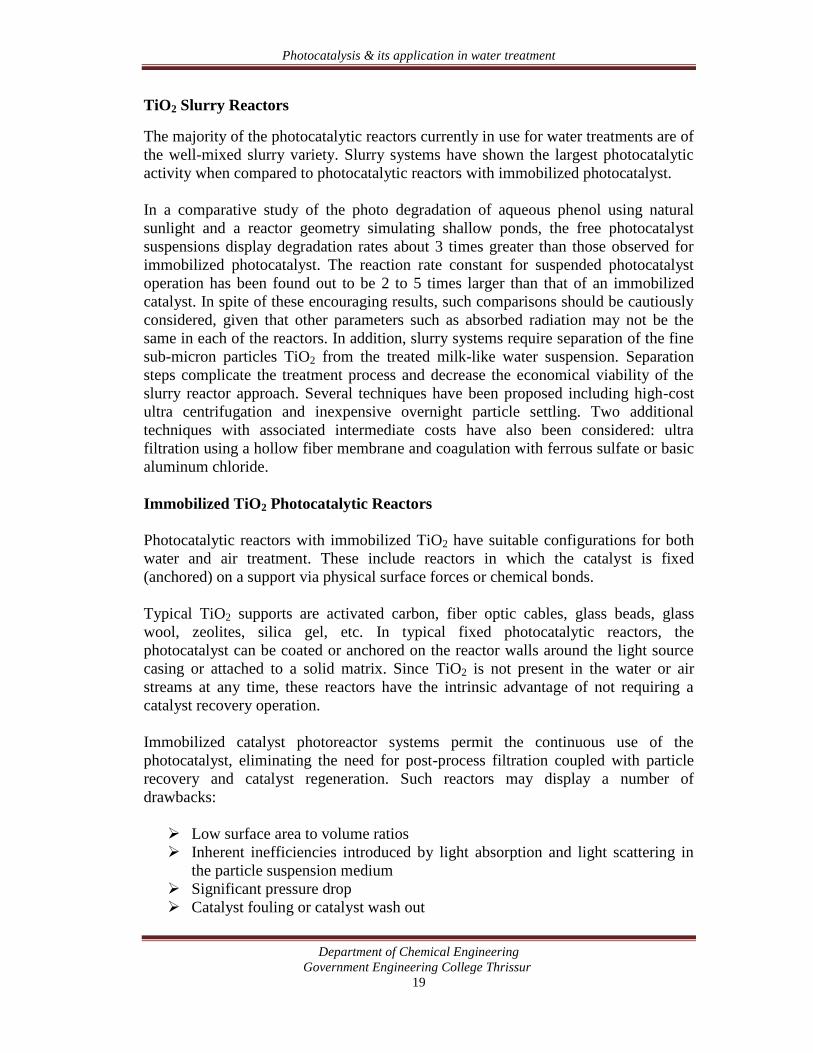
(c) Integrated Flow Reactor Membrane with Filtration System (IFR-MF): TheIFRMF involves an annular, well-mixed, slurry batch including a hollow-fibermembrane with ultra-filtration capabilities. The IFR-MF allows the TiO2
particle separation from the treated water as well as the recycle of TiO2 to thereactor. Fig #7 illustrates the reactor.
Fig #7: Integrated flow reactor membrane with filtration system
Photocatalysis & its application in water treatment
Department of Chemical EngineeringGovernment Engineering College Thrissur
21
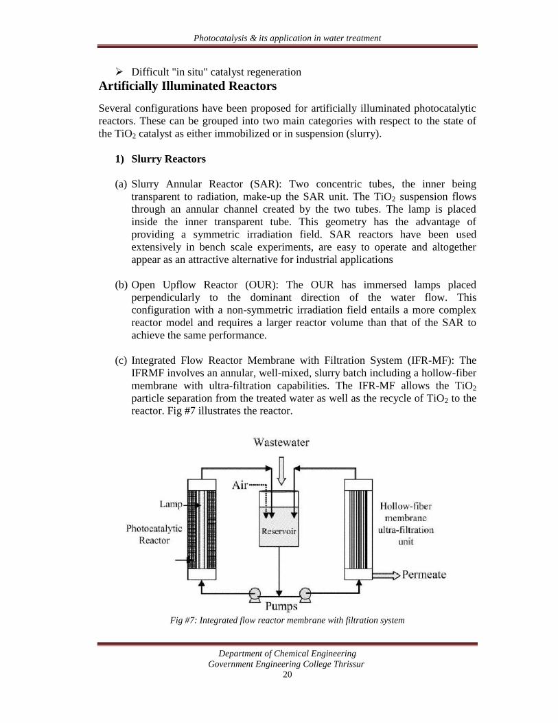
(d) Taylor Vortex Reactor (TVR): The TVR Fig#8 consists of two coaxialcylinders and free-flowing particle slurry circulating in the annular channel.Light bulbs are mounted in the inner cylinder. A vortex-induced fluidinstability is generated via inner cylinder rotation. The catalyst is irradiatedperiodically as vortices move catalyst particles closer to the irradiated reactorsection. Optimum operating conditions of 300-rpm inner cylinder rotation anda catalyst loading of 10 g/L provide an efficiency that is three times largerthan that of a conventional slurry reactor. A disadvantage of the TVRconfiguration is the added complexity of its moving parts.
Fig #8: Taylor Vortex Reactor
(e) Swirl Flow Reactor (SFR): Two circular glass plates constitute the SFRreactor The TiO2 water suspension is injected tangentially in the outer reactorsection creating a swirl and promoting high mixing of the TiO2 suspension.The TiO2 suspension leaves the unit from the center of a top plate. This unitprovides a well-mixed slurry with potentially non-uniform irradiation, whichresults in an associated complex reactor model.
Photocatalysis & its application in water treatment
Department of Chemical EngineeringGovernment Engineering College Thrissur
22
2) Immobilized TiO2 reactors
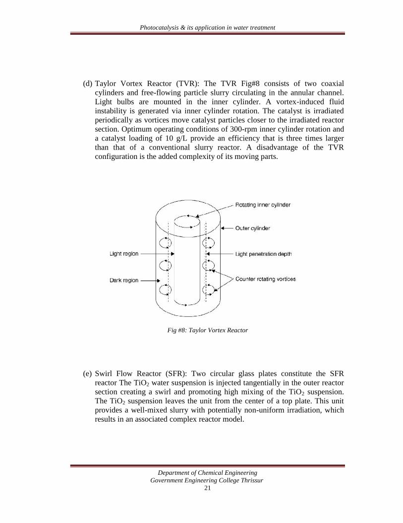
(a) Falling Film Reactor (FFR): The FFR is recognizable by the followingcomponents:
The immobilized TiO2 coating the internal column wall A descending film of water A lamp placed in the central section of the column.
This reactor configuration may only provide a limited active catalyst surface per unitreactor volume.
Fig #9: Falling film reactor
(b) Fiber Optic Cable Reactor (FOCR): The FOCR is designed with fiber opticcables bringing irradiation to the supported TiO2. This system can allow theirradiation of a remotely located photocatalyst with minimum scattering anduniform irradiation. The cost of optic fibers and the energy losses during beamfocusing and photon transfer are two disadvantages that can lessen the appealof the FOCR design. A typical FOCR includes Degussa P25 immobilized onquartz optical fibers and a Xe arc UV-radiation lamp.
(c) Packed Bed Reactor (PBR): The PBR is an annular packed unit irradiated by acentral lamp. A possible drawback of the PBR results from the uneven orpartial photocatalyst irradiation. Uneven flow distribution may also limit theamount of water contacting the irradiated TiO2 and negatively influencing theoverall PBR unit's performance.
Photocatalysis & its application in water treatment
Department of Chemical EngineeringGovernment Engineering College Thrissur
23
Solar Photovoltaic reactor designs
Most of the reactor designs tested for the photo oxidation of organic pollutants bysolar radiation are TiO2 slurry reactors. The implementation of solar photocatalyticreactors has occurred concurrently with advances in the design of solar thermalcollectors, given the important characteristics shared by these units. There are,however, specific constraints for the design of solar photocatalytic reactors.
• The need of UV transparent materials• Reduced insulation requirements, given that the reactor temperature has a smalleffect on the aqueous phase photoreactions.
According to the received irradiation, solar reactors can be divided into concentratingor non-concentrating (or one sun) reactors depending on the irradiation received. Forthe same harvesting area, concentrating reactors require smaller volumes than nonconcentrating reactors. When land cost is a concern, the use of more expensivecomponents can be justified without unreasonably increasing the overall unit cost.Non-concentrating reactors involve negligible optical losses due to the reflectivesurfaces; therefore, these reactors can benefit from both direct and diffuse sunirradiation. In fact, non-concentrating reactors can continue their operation undercloudy conditions when only diffuse solar light is available. Furthermore, under clearsky conditions, they can take advantage of the diffuse sun irradiation component,close to 50% of the total available UV light. Finally, non-concentrating reactors tendto be more efficient than concentrating units given that at high-energy flux densitiesthe reaction rate depends on a fraction of the power irradiation intensity.
Solar photocatalytic reactors can be operated in either continuous single pass mode ordiscontinuous batch mode. In the continuous single pass mode, complete oxidation ofthe contaminant is achieved in a single pass with the water flow rate being adjustedfor fixed solar flux densities. On the other hand, batch mode operation requires a setvolume of water to be treated with varying solar flux densities.
Main types of solar reactors
a) Parabolic Trough Reactors (PTR) are concentrating-type units configured with atubular reactor section and a parabolic reflecting trough. The reflector concentratesthe sunlight to an aperture on the reactor tube. A one or two-axis sun tracking systemis recommended for adequate operation.
b) Parabolic collecting reactors are trough reactors without light concentratingdevices. Reflectors in these reactors consist of two half-cylinders of parabolic profileenabling the light to enter from virtually any direction and to be reflected into thetubular reactor. The principal advantages of these units are a very limited mass
Photocatalysis & its application in water treatment
Department of Chemical EngineeringGovernment Engineering College Thrissur
24
transfer limitation due to turbulent conditions and a nearly close-systemconfiguration, which minimizes the vaporization of volatile contaminants. Thisconfiguration presents, however, the following potential drawbacks:
• It solely uses direct UV irradiation• It displays low optical efficiency• It requires an oxygen injection• It involves high investment cost• It requires a post-separation step of TiO2
c) The non-concentrating double skin reactor is a slurry type flat plate unit,which is designed using a modified double skin Plexiglas sheet. Water flows througha thin slit formed in between two Plexiglas sheets. Their principal advantages are:
• Possible use of the complete UV irradiation spectrum• Operation of the unit under turbulent flow conditions• Nearly sealed reactor with no vaporization of contaminants• Simple construction• Low investment cost.
Their main disadvantages could be:
• Low optical efficiency• Large irradiation area for the purification of large volumes of water• Need of separation of TiO2 particles• Bubble entrapment resulting from aeration.
d) The non-concentrating thin film fixed bed configuration consists of an inclinedglass plate coated with photocatalyst. The polluted water flows along the inclinedglass panel forming a thin film (100 microns). Their main advantages are
• Possible use of the complete UV irradiation spectrum• High optical efficiency• Simple construction• No need of TiO2 particles' separation.
The main drawbacks of this configuration are:
• Laminar flow conditions• Vaporization of volatile contaminants• Catalyst film exposed to pollution agents• Large area required for treating large water volumes.
e) The non-concentrating flat plate configuration consists of a rectangular flatplate with a thin glass cover. The photocatalyst is suspended in the water phase
Photocatalysis & its application in water treatment
Department of Chemical EngineeringGovernment Engineering College Thrissur
25
forming slurry. This design prevents the contact between the wastewater and theambient air. A spray bar located near the top of the reactor evenly distributes thewastewater.
In summary, there are a number of available photocatalytic reactor configurations forthe photoconversion of water pollutants. These reactors are based on either suspendedor immobilized TiO2. It is expected that enhanced energy efficiencies could beachieved by improving the engineering of the above-described designs. This couldconsiderably expand the prospects of the use of photocatalysis for water purification.
Photocatalysis & its application in water treatment
Department of Chemical EngineeringGovernment Engineering College Thrissur
26
CONCLUSION
Owing to the convenience with which we could handle photocatalytic reactors, theycould become the main method of waste water treatment in the near future. Researchis also going on to see the possibilities of using visible light for the purpose of photoexcitation of the catalyst.
Heterogeneous photocatalysis using semiconductors such as titanium dioxide can bemore interesting than conventional methods for removing organic species in theenvironment. Because the process gradually breaks down the contaminant molecule,no residue of the original material remains and therefore no sludge requiring disposalto landfill is produced. The catalyst itself is unchanged during the process and noconsumable chemicals are required. This results in considerable savings and a simpleroperation of the equipment involved. Additionally, because the contaminant isattracted strongly to the surface of the catalyst, the process will continue to work atvery low concentrations allowing sub part-per-million consents to be achieved. Takentogether, these advantages mean that the process results in considerable savings in thewater production cost and keeping the environment clean.
Photocatalysis & its application in water treatment
Department of Chemical EngineeringGovernment Engineering College Thrissur
27
REFERENCES
1) Chemical Reaction Engineering – Octave Levespiel2) Photocatalysis Papers Review – Bunsho Octani et. al.3) http://en.wikipedia.org/wiki/Enzyme4) Legrini et. al., 1993; Hoffman et. al., 1995; Turchi and QUis, 19905) Photocatalytic Reaction Engineering by Hugo de Lasa, Benito Serano, Migual
Salaices6) Water Treatment by Heterogeneous Photocatalysis: An Overview by Radwan
A. Al Rasheed, Saline Water Desalination Research Institute
Related Documents