PHOTO FACT* Folder TELE KING MODELS 41O, 512, 612, 71O VOLUME CONTROL ON-OFF SWITCH HORIZ VERT. HOLD CONTRAST BRIGHTNESS CHANNEL SELECTOR FINE TUNING TELE KING MODEL 410 TRADE NAME Tele King Models 410, 512, 612, 710 MANUFACTURER Tele King Corp. , 601 W. 26th St., New York 1, New York TYPE SET Television Receiver TUBES Twenty POWER SUPPLY 110-120 Volts AC-60 Cycle TUNING RANGE-Channels 2 thru 13 RATING 1. 62 Amp. at 117 Volts AC Alignment Instructions 6 Block Diagram 13 Horiz. Osc. Adjustment 6 Parts List and Description 14,15,16 Photographs Cabinet-Rear View 7 Capacitor Identification 11,18 Chassis-Top View 3,7 INDEX Photographs (continued) RF Tuner 10 Resistor Identification 12,17 Trans., Inductor and Alignment Identification.. . 4, 9 S chematic 2 Tube Placement Chart 5 Voltage and Resistance Measurements 8 o o m O m > in 2 3 Z to N ^ O HOWARD W. SAMS & CO., INC. • Indianapolis 1, Indiana "The listing of any available replacement part herein does not constitute in any case a recommendation, warranty or guaranty by Howard W. Sams & Co., Inc., as to the quality and suitability of such replacement part. The numbers of these parts have been compiled from information furnished to Howard W. Sams & Co., Inc., by the manufacturers of the particular type of replacement part listed." "Reproduction or use, without express permission, of editorial or pictorial con- tent, in any manner, is prohibited. No patent liability is assumed with respect to the use of the information contained herein. Copyright 1950 by Howard W. Sams & Co., Inc., Indianapolis 1, Indiana, U. S. of America. Copyright under In- ternational Copyright Union. All rights reserved under Inter-American Copyright Union (1 91 0) by Howard W. Sams & Co., Inc." Printed in U. S. of America DATE 3- 50 SET 88 FOLDER 12

Welcome message from author
This document is posted to help you gain knowledge. Please leave a comment to let me know what you think about it! Share it to your friends and learn new things together.
Transcript

PHOTO FACT* FolderTELE KING
MODELS 41O, 512, 612, 71O
VOLUME CONTROLON-OFF SWITCH
HORIZVERT.HOLD
CONTRASTBRIGHTNESS
CHANNELSELECTORFINE TUNING
TELE KING MODEL 410
TRADE NAME Tele King Models 410, 512, 612, 710MANUFACTURER Tele King Corp. , 601 W. 26th St., New York 1, New YorkTYPE SET Television ReceiverTUBES Twenty
POWER SUPPLY 110-120 Volts AC-60 CycleTUNING RANGE-Channels 2 thru 13
RATING 1. 62 Amp. at 117 Volts AC
Alignment Instructions 6
Block Diagram 13
Horiz. Osc. Adjustment 6
Parts List and Description 14,15,16
PhotographsCabinet-Rear View 7
Capacitor Identification 11,18
Chassis-Top View 3,7
INDEXPhotographs (continued)
RF Tuner 10
Resistor Identification 12,17
Trans., Inductor and Alignment Identification.. . 4, 9
S chematic 2
Tube Placement Chart 5
Voltage and Resistance Measurements 8
oom
O m>in 23 Z
toN
O
HOWARD W. SAMS & CO., INC. • Indianapolis 1, Indiana
"The listing of any available replacement part herein does not constitute in anycase a recommendation, warranty or guaranty by Howard W. Sams & Co., Inc.,as to the quality and suitability of such replacement part. The numbers of theseparts have been compiled from information furnished to Howard W. Sams & Co.,Inc., by the manufacturers of the particular type of replacement part listed.""Reproduction or use, without express permission, of editorial or pictorial con-
tent, in any manner, is prohibited. No patent liability is assumed with respect tothe use of the information contained herein. Copyright 1950 by Howard W.Sams & Co., Inc., Indianapolis 1, Indiana, U. S. of America. Copyright under In-ternational Copyright Union. All rights reserved under Inter-American CopyrightUnion (1 91 0) by Howard W. Sams & Co., Inc." Printed in U. S. of America
DATE 3- 50 SET 88 FOLDER 12

THE COOPERATION OF THE MANUFACTURER OF THIS
RECEIVER MAKES IT POSSIBLE TO BRING YOU THIS SERVICE
A PHOTOFACT STANDARD NOTATION SCHEMATIC
©Howard W. Sams & Co., Inc. 1950
PAGE 2

AUDIO OUTPUT
jz) 6AQ5si

88-12
TELE
KIN
GM
OD
EL
S 4
10
, 5
12
, 6
12
, 7
12
M3IA
dO
l S
ISS
VhD

(m)

EfiS
?*
. V
^V
u"
CH
AS
SIS
B
OT
TO
M V
IEW
-TR
AN
S.J
ND
UC
TO
R A
ND
ALI
GN
ME
NT
ID
EN
TIF
ICA
TIO
N
LIZ
. '£
L9 'ti
S
'OL
fr S
13Q
OW
9N
IX
3131

VID
EO
DE
T.-
AG
C3H
D.V
IDE
OIF
2
.ND
VID
EO
IF
HO
R.
OU
T F
>UT
H O
RZ
.MU
LT.
AU
DIO
OU
TPLT
T
/V\
RF
AM
P
(V4 \T
VID
EO
IF
2ND
VID
EO
IF3R
DV
IDE
O1F
V
IDE
O D
ET
A7i
o\
SO
UN
D I
F
/V
9\
BO
TT
OM
V
IEW
AU
DIO
O
UTP
UT
VIS
\
VI6
\
V!7
V 6S
N7G
TJ
\6
j I
6W
4G6y
|HO
RIZ
.MU
LT
V.
^
DA
MP
ER
, H
OR
IZ. O
UTP
UT
I I
VIS
IB3G
T ,
TU
BE
P
LAC
EM
EN
T C
HA
RT
siaa
ow
9N
IX 3
131

ALIGNMENT INSTRUCTIONS
To eliminate the high voltage shock hazard remove the horizontal oscillator tube (V15) from its socket.VIDEO IF ALIGNMENT
The use of a VTVM with an AC scale is necessary to align the video IF stages, do not attempt to connect the VTVM across the diode load resistor.Remove the local oscillator tube (V3) from its socket to prevent erroneous indications.Set the contrast control to slightly less than maximum clockwise.
DUMMYANTENNA
Direct
Direct
SIGNALGENERATORCOUPLING
High side to ungroundedtube shield floating overmixer tube (V2). Lowside to chassis.
SIGNALGENERATORFREQUENCY
25.6MC(400 - AMmodulated)
23.4MC(400 - AMmodulated)
CHANNEL
Any
CONNECTVTVM
AC Probe to Point<£>Common to chassis,(see instructionsabove)
"
ADJUST
A1.A2
A3.A4
REMARKS
Adjust for maximum deflection.
OVERAtt VIDEO IF RESPONSE CHECKConnect the synchronized sweep voltage from the signal generator to the horizontal input of the oscilloscope for horizontal deflection.
DUMMYANTENNA
Direct
SWEEPGENERATORCOUPLING
High side to ungroundedtube shield floating overmixer tube (V2). Lowside to chassis.
SWEEPGENERATORFREQUENCY25MC(10MC SWP)
MARKERGENERATORFREQUENCY26. IMC25.6MC22.6MC21.6MC
CHANNEL
Any
CONNECTSCOPE
Vert. Amp. to Point<Q> Low side to chas-sis.
ADJUST REMARKS
Check for response curve similar to Fig 1with markers as shown. If necessaryretouch Al thru A4 for proper response.
SOUND IF ALIGNMENT USING AM SIGNAL GENERATOR AND VTVMConnect a matched pair of 100KJ2 resistors between points B, and C. The junction of these resistors is alignment point E.
DUMMYANTENNA
. 01MFD
. 01MFD
SIGNALGENERATORCOUPLING
High side to pin 4 (Grid)of 6AC7 (V8) . Low sideto chassis.
SIGNALGENERATORFREQUENCY
4. SMC(Unmod.)
CHANNEL
Any chan-nel notused local-ly
"
CONNECTVTVM
DC Probe to PoinKrpCommon to Point<C>
DC Probe to Point<^>Common to Point<jS
ADJUST
AS, A6,A7
A8
REMARKS
Adjust for maximum deflection.
Adjust for zero reading. A positive and negativereading will be obtained on either side of the correctsetting.
SOUND IF ALIGNMENT USING FM SIGNAL GENERATOR AND OSCILLOSCOPE
Use frequency modulated signal with 60 ~ modulation and 450KC sweep. Use 120 ~ sawtooth voltage in scope for horizontal deflection.
DUMMYANTENNA
. 01MFD
. 01MFD
SWEEPGENERATORCOUPLING
High side to pin 4 (Grid)of 6AC7 (V8). Low sideto chassis.
SWEEPGENERATORFREQUENCY
4. SMC(450KC SWP)
MARKERGENERATORFREQUENCY
4. SMC
CHANNEL
Anychannelnot usedlocally.
CONNECTSCOPE
Yert. Amp. to Point<^> Low side to chas-sis.
Vert. Amp. to Point<£> Low side to chas-sis.
ADJUST
A5.A6,A7
A8
REMARKS
Disconnect stabilizer capacitor C6. Adjustfor maximum amplitude and symmetry asper Fig 2.
Reconnect capacitor C6. Adjust A8 so4. SMC occurs at center of crossover linesas per Fig 3 . SLIGHTLY retouch A7 formaximum amplitude and straightness ofcrossover lines.
TINER ALIGNMENTThe circuits in the tuner have been pre-set at the factory and are sufficiently broad and should not require adjustment in the field.
FIG. I FIG. 2 F,G 3
HORIZONTAL OSCILLATOR ADJUSTMENTS
Turn the set on and tune in a TV station, preferably a test pattern.
Set the horizontal hold control to the mid position of its range. Adjust the horizontal frequency slug (BI) until the picture synchronizes
horizontally.
Turn the horizontal drive t r immer (B2) clockwise as far as possible without crowding the right side of the picture.
Adjust the width slug (B3) until the picture fills the mask horizontally.
Adjust the horizontal linearity slug until the picture is symmetrical from left to right, readjustment of B2 may be required to obtain
optimum results.
PAGE 6

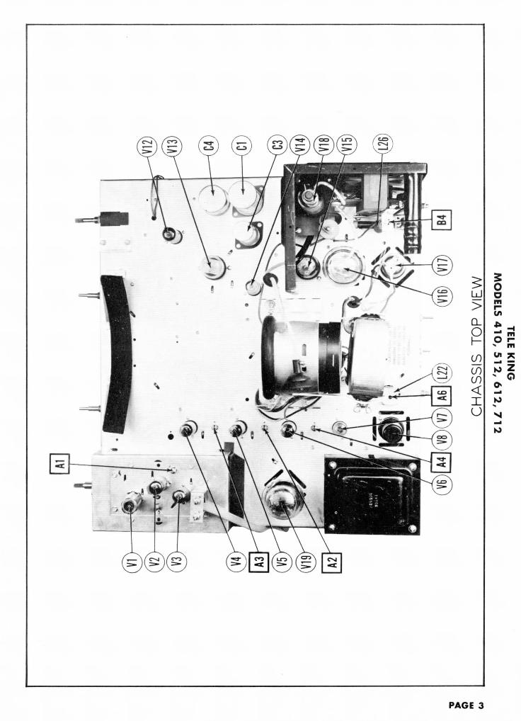
CHASSIS-TOP VIEW
VER"
LIN
VERT SOUND HORlZ, HORIZ
SIZE DISC. FREQ. DRIVEi WIDTH
CABINET-REAR VIEW
PAGE 7

VO
LTA
GE
AN
D R
ES
IST
AN
CE
ME
AS
UR
EM
EN
TS
VOLT
AGE
READ
ING
SRE
SIST
ANCE
REA
DING
S
Item
V
1
V
2
V
3
V
4
V 5
V 6
V 7
V 8
V9
V
10
V 1
1
V 1
2
V 1
3
V1
4
V
15
V
16
V
17
vie
V
19
V2
0
Tube
6BH
6
6AG
5
6J6
6AU
6
6AU
6
6AU
6
6AL
5
6AC
7
12A
U7
6AU
6
6T8
6AQ
5
6SN
7GT
6AL
5
6SN
7GT
6BG
6G
6W4G
T
1B3G
T
5U4G
12L
P4
Pin
1
- . 4
VD
C
-1V
DC
95V
DC
-1.9
VD
C
-.1V
DC
0V.
0V.
0V.
2.S
VD
C
tl.l
VD
C
t-.4
VD
C
t-.6
VD
C
-20V
DC
0V.
.1V
DC
0V.
0V.
Pin
2
.1V
DC
0V
.
95V
DC
0V
.
0V
.
0V
.
-3V
DC
6. 3
VA
C
0V
.
f7.2
VD
C
t-.8
VD
C
tov.
75V
DC
185V
DC
0V.
250T
OC
6. 3
VA
C
0V.
Pin
3
0V.
6 . 3
V A
C
6. 3
VA
C
6. 3
VA
C
6. 3
VA
C
6. 3
VA
C
6. 3
VA
C
2.8V
DC
.7V
DC
tov.
t-.4
VD
C
tov.
0V.
0V.
10V
DC
7VD
C
430V
DC
Pin
4
6. 3
VA
C
0V.
0V.
0V.
0V.
0V.
0V.
-2.5
VD
C
0V.
te.s
vAc
te . S
VAC
te.s
vAc
ov.
6. 3
VA
C
ov.
ov.
ov.
Pin
5
55V
DC
55V
DC
§-2
.2V
DC
55V
DC
55V
DC
55V
DC
-1.6
VD
C
2.8V
DC
OV
.
tSSO
VD
C
tov.
t!45
VD
C
290V
DC
1.8V
DC
105V
DC
-4V
DC
360V
DC
Pin
6
55V
DC
55V
DC
i-2
.5V
DC
S5V
DC
55V
DC
55V
DC
OV
.
185V
DC
340V
DC
f90V
DC
OV
.
tlB
OV
DC
5VD
C15
VD
C
OV
.
10V
DC
OV
.
380V
DC
Pin
7
OV
.
OV
.
.4V
DC
.2V
DC
.2V
DC
.4V
DC
- . 6
VD
C
OV
.
OV
.
t7.2
VD
C
tov.
t- .
6VD
C
OV
.
-1.2
VD
C
OV
.
OV
.
tov.
Pin
8
110V
DC
17V
DC
tov.
6 . S
VA
C
6.3
VA
C
250V
DC
t6.3
VA
C
Pin
9
6. 3
VA
C
t85V
DC
* D
O N
OT
ME
AS
UR
E.
0V.
6. 3
VA
C
390V
DC
1.3V
DC
0V.
PIN
10
360V
DC
3 80
VA
CPI
N
1111
0VD
C
-3V
DC
PIN
12
OV
.
3 80
VA
CO
V.
390V
DC
item
V 1
V 2
V 3
V 4
V5
V 6
V 7
V 8
V9
V
10
V 1
1
V
12
V
13
V
14
V
15
V
16
V
17
V 1
8
V
19
V2
0
Tuba
6BH
6
6AG
5
6J6
6AU
6
6AU
6
6AU
6
6AL
5
6AC
7
12A
U7
6AU
6
6T8
6AQ
5
6SN
7GT
6AL
5
6SN
7GT
6BG
6G
6W4G
T
1B3G
T
5U4G
12L
P4
Pin
1
2.6
Meg
.
IMe
g.
tiooo
n
1.6
Meg
.
1.6
Meg
.
.If!
i.sn
on 47K
S2
t47
0K
n
tln
f.
250K
n
2 M
eg.
27K
n
5. I
Me
g.
Inf.
Inf.
Inf.
Inf. .in
Pin
2
IOO
JJ
on tlO
OO
n
on on on looo
n
.in on tiooo
n
t44
Kn
ton
02
.5 M
eg.
»900
Kn
27K
O
»28K
fi
.in Inf.
Inf.
20K
B
270K
n
Pin
3
on .in .in .in .in .in .in 7 son
270K
B
ton
tln
f.
ton
on on i.5K
n
82n
50K
n
Inf.
Inf.
PIN
10
noon
Pin
4
.in on on on on on on 9.2
Kn
on t.m
t.in t.m
2.2
Me;
.
.in HO
Kn
on Inf.
Inf. eon
PIN
11
80K
B
Pin
5
tiooo
n
tiooo
n
looK
n
tsoo
nt2
00n
tioon
9Kn
7 son
on moo
on
ton
uioo
on
iiSKn
4. 8
Meg
.
#300
KB
1 M
eg.
f22
0n
Inf. isn
PIN
12
on
Pin
6
tiooo
n
tiooo
n
looK
n
tsoo
nt2
00n
tioon
on 22K
n
#32K
n
TSS
Kn
Inf.
i20o
n3
.3K
nss
onon i.S
Kn
Inf.
1230
n
Inf. ssn
Pin
7
on on 47n
82B
82n
82n
680K
n
on IMeg
.
tiooo
n
ton
250K
n
on 4.8
Meg
.
on on ton
Inf.
Inf.
Pin
8
t5.6
Kn
3.9
Kn
t47
0K
n
.in .in 58
.5K
n
t.m
Inf.
20K
n
Pin
9
.in f330
Kn
TO
P C
AP
»200
B
TO
P C
AP
*360
n
§ T
AK
EN
WIT
H V
AC
UU
M T
UB
E V
OL
TM
ET
ER
.*
DO
NO
T
ME
AS
UR
E.
T M
EA
SU
RE
D F
RO
M P
IN
2 O
F V
12.
t M
EA
SU
RE
D
FR
OM
PIN
2 O
F V
12.
# M
EA
SU
RE
D
FRO
M P
IN
3 O
F V
L7.
f M
EA
SU
RE
D F
RO
M P
IN 8
OF
V1
9.
1. D
C
Vol
tage
m
easu
rem
ents
ar
e of
20
,000
4.
Li
ne v
olta
ge m
aint
aine
d at
117
vol
ts f
or v
olt-
ohm
s pe
r vol
t; A
C V
olta
ge m
easu
red
at 1
,000
a
ge
re
ad
ing
s.
2.
Pin
num
bers
are
cou
nted
in a
clo
ckw
ise
dire
c-tio
n on
bot
tom
of
sock
et.
3. M
easu
red
valu
es a
re f
rom
soc
ket
pin
to c
om
-m
on n
egat
ive
unle
ss o
ther
wis
e st
ated
.
5.
Fron
t pa
nels
con
trol
s se
t at
min
imum
.
6.
Whe
re r
eadi
ngs
may
va
ry a
ccor
ding
to
the
setti
ng o
f th
e se
rvic
e co
ntro
ls,
both
min
imum
and
max
imum
rea
ding
s ar
e gi
ven.

C18HC19 C20 R12 R11 C14
RF TUNER-RIGHT SIDE
RF TUNER-LEFT SIDE
PAGE 1O

si aovd
X

L4«j
CH
AS
SIS
B
OT
TO
M
VIE
W-C
AP
AC
ITO
R
IDE
NT
IFIC
AT
ION
1\L
'Z
19
'C
IS '
Olf
r S
13
00
WO
NI*
3131


o m NC
HA
SS
IS
BO
TT
OM
VIE
W-R
ES
IST
OR
ID
EN
TIF
ICA
TIO
N'£
L9 '
£IS
'O
lfr
S13
QO
WO
NIX
313
1

AF
AM
P.
J V
ll
AU
DIO
OU
TP
UT
V12
}R
F A
MP
. V
I I
MIX
ER
V2
1
OSC
. V
3
|I
lst
VID
EO
IF
AM
P.
V4 k
„ 9n
H v
rnc
nii
r S
MD
V
R •
t
VID
E
3rd
VID
EO I
F A
MP
. V
6 •
AG
C
•
B++
B
+ B
-
HO
RIZ
. O
UT
PUT
V
16
DA
MP
ER
V
17
HV
RE
CT
. V
18
BLO
CK
D
IAG
RA
M
S130
OWO
NIX
313
1

TUBES (SYLVANIA or Equivalent)PARTS LIST Al
CAPACI"
ITEMNo.
VIV2V3A
BV4V5V6V7
V8V9
V10Vll
V12V13
V14V15V16V17V18V19V20A
B
USE
RF Amp.MixerOscillatorOscillator1st Video IF2nd Video IF3rd Video IFVideo Del. -AGCRectifierVideo Amp.DC Restorer-Sync.Sep. -Phase Inv.Sound IF Amp.Ratio Del. -AFAmp.Audio OutputVert. Osc.-Vert.Amp.Hor. Phase Del.Hor. Multivib.Hor. OutputDamperHV RectifierLV RectifierPicture TubePicture Tube
REPLACEMENT DATATELE-KING
PART No.
6BH66AG56J66C46AU66AU66AU6
6AL56AC7
12AU76AU6
6T86AQ5
6SN7GT6AL56SN7GT6BG6G6W4GT1B3GT5U4G12LP410BP4
STANDARDREPLACEMENT
6BH66AG56166C46AU66AU66AU6
6AL56AC7
12AU76AU6
6T86AQ5
6SN7GT6AL56SN7GT6BG6G6W4GT1B3GT5U4G12LP410BP4
RMABASETYPE
7CM7BD7BF6BG7BK7BK7BK
6BT8N
9A7BK
9E7BZ
8BD6BT8BD5BT4CG3C5T12D12D
NOTES
CAPACITORSCapacity values given in the rating column are in mfd. for Electrolyticand Paper Capacitors, and in mmfd. for Mica and Ceramic Capacitors.
ITEMNo.
C55C56C57CSSC59C60C61C62C63C64C65C66C67C68C69C70C71C72C73C74C75C76C77C78C79C80C81C82C83C84C85
RATINGCAP.
.00522
01.002.005.005005125001
.001
.05
.01
.005;0539003303902702222.05.25.1.035.001.001.25500.1.1
VOLT
60050060060060060060060040060060040040060040050050050050050050060040060060060060040010000600600
REPLACEM!TELE -KING
PART No.
CP-4-25CM-4-22CP-4-11CP-4-22CP-4-25CP-4-25CP-4-25CP-4-01CP-4-025CP-4-21CP-4-21CP-4-15CP-4-11CP-4-25CP-4-15CM-239CM-333CM-339CM-327
CP-6-15CP-4-025CO-6-01CO-6-135
CP-4-025CHV-35CP-4-01CP-4-01
AEROVOXPART No.
P688-005GP22MP688-01P688-002P688-005P688-005P688-005P688-1P488-25P688-001P688-001P488-05P488-01P688-005P488-05
GP330MGP390MGP270MGP22MGP22MP688-05P488-25P688-1P688-033P688-001P688-001P488-25
P688-1P688-1
C<D
P>
PT5WPTPTPTPTPTPTGTPTPTPTPTPTPT
5W5W5W5W5WPTGTPT:
PT:PT]GT'
PTIPT]
* Not used in all models.t Some models use 12MMF 1500 volt rating in place oft Parallel sections to obtain desired capacity.
ITEMNo.
CIABC
C2C3A
BC4A
BCD
C5C6C7C8C9CIOCllC12C13C14CISC16C17CISC19C20C21C22C23C24C25A
BC26C27C28C29A
BC30C31A
BC32C33C34C35C36C37C38C39C40C41C42C43C44C45C46C47C48C49C50C51C52C53C54
RATINGCAP.
404040405005020101010100110103603601203601.4722150014.74.736036036020002000200020002000100200020002000100200020002000
I1001202000.011
2000i
2000680470
139
02005020010020050050205
VOLT
45045045045051504504504504502525
600
400600
600
400600400600600600600400400
REPLACEMENT DATATELE-KING
PART No.
CEM-5
CET-4CEM-7
CEM-6
CET-5CET-6
CC-22CC-22CCD-22
CC-22CC-31CC-22CCD-22
CC-31CCD-22
CC-22CP-4-01CC-31CC-312CC-22CP-4-11CP-4-01CC-22CC-55CC-22CC-368CC-247CP-4-01CC-439CP-4-12CP-4-25CP- -12CP- -21CP- -22CP- -25CP- -25CP- -12CP-4-15
AEROVOXPART No.
AFH8B8J
E26D67AFH100T10D
AFH422J2D
PRS25/100E26E42GP10MGP10MGP360MGP360MGP120MGP360M
GP22MGP1500M
SI4.7DN750SI4.7DN750GP360MGP360MGP360MGP2000MGP2000MGP2000MGP2000MGP2000MGP100MGP2000MGP2000MGP2000MGP100MGP2000MGP2000MGP2000MP688-1GP100MGP120MGP2000MP488-01P688-1GP2000M .GP5MGP2000MGP680MGP470MP688-1GP39MP488-02P688-005P488-02P688-001P688-002P688-005P688-005P488-02P488-05
CORNELL-DUBILIER
PART No.UP11CJ1098
BR4045AUP5015
LBRH605UP8DJ1112
BRH251ABR145
1W5D21W5D21W5D21W5D21W5D25W5T11W5D21W5D21W5D25W5T11W5D21W5D21W5D2PTE6P15W5TI5W5T151W5D2PTE4S1PTE6P11W5D25W5V51W5D21W5T75W5T5PTE6P15W5Q4PTE4S2PTE6D5PTE4S2PTE6D1PTE6D2PTE6D5PTE6D5PTE4S2PTE4S5
ERIEPART No.
NPOK-10NPOK-10GP2K-390GP2K-390GP2K-120GP2K-390
GP2K-22GP2L-0015
N750K-5N750K-5GP2K-390GP2K-390GP2K-390GP2M-002GP2M-002GP2M-002 'GP2M-002 .GP2M-002GP1K-100GP2M-002GP2M-002 'GP2M-002GP1K-100GP2M-002 'GP2M-002GP2M-002
GP1K-100GP2K-120GP2M-002821-01
GP2M-002NPOK-5GP2M-002GP2K-680GP2K-470
GP1K-39
811-005
GP2L-001GP2M-002811-005811-005
SPRAGUEPART No
TVL-304
TVA-24EL-52UT-501EJL-410tTVA-21
TVA-8TVA-11
29C229C2
*9C5 1
29C21FM-3129C2
29C5 1
29C2
!9C5
29C2TM-1FM-31FM-315
29C2TM-11TM-129C2MS-5529C21FM-375FM-35
TM-1FM-44
TM-12TM-25TM-12TM-21TM-22TM-25TM-25TM-12TM-15
IDENTIFICATION CODESAND
INSTALLATION NOTES
. Filter• Filteri FilterOutput Decoupling• Bias FilterA Decoupling• Decoupling• Vert. Output DecouplingA DecouplingV, Amp. Screen BypassVert. Output Cath. BypassStabilizing Cap.Fixed TrimmerFixed TrimmerRF CouplingRF Cathode BypassRF DecouplingRF Filament BypassRF CouplingRF CouplingRF CouplingMixer DecouplingOsc. CouplingOsc. FeedbackOsc. FeedbackOsc. Filament BypassRF BypassIF CouplingMixer Decoupling *AGC Filter *AGC Filter1st V. IF Decoupling1st V. IF Fil. BypassIF CouplingAGC Filter »2nd V. IF Decoupling2nd V. IF Fil. BypassIF Coupling3rd V. IF Cath. Bypass3rd V. IF Decoupling3rd V. IF Fil. BypassAGC FilterIF CouplingIF CouplingRF BypassDAGC DecouplingBias FilterBias FilterV. Diode FilterV. Det. -AGC Fil. BypassV. Amp. Cath. BypassV. Amp. Cath. BypassVideo CouplingS. IF CouplingS. IF DecouplingS. IF Screen BypassS. IF DecouplingDiode Load Cap.De-emphasisAudio CouplingAudio CouplingAudio CouplingBias Filter
ccITEMNo.
R1AB
R2ABC
R3AB
R4R5R6
RATING
RESIST-ANCE
500KSJSwitchIMeg.50KIJ
Shaft End750f!100KS!3000J!2.5Meg.15000
WATTSI
5|
2i
1i
3
REPLACEMENT DATATELE -KING
PART No.
P-7Not Req.
) /PD-5 <
) IPD-4
P-5P-6
IRCPART No.
Q13-13376-1Bll-137 § ]Bll-123 i )E187 § I
Qll-239
CUf t
M-6SW-
PD-
PD-
M-810-1'
§ Additional parts to be used with "Concentrikit",Note 1. Some models use SOOOn control, part No. P-2
Rl
ITEMNo.
R7R8R9RIOR1IR12R13R14R15R16R17R18R19R20R21R22R23R24R25R26R27R28R29R30R31R32R33R34R35R36R37R38R39R40R41
RATING
RESISTANCEIMeg. 20%100SJ 5%1000S2 20%4700S! 5%4700S! 5%1 Meg. 20%1000S2 5%IOOKSJlooKn47SJ 20%moon 20%330S!330SZioonlOKn820100SJ82oonB2S1100C)8200B82SJioon1 Meg.680KS239KSJ1000SJ 20%8200S2120f!54KSI54KB44KR44KSJ22KSJ5600S2
WATTSi
I4I22
1
I
f2IZ
1
I
I
I
&
1
2
1
1
i
I
;;if2I
±
1
1
I
|
222211
REPLACEMENT DATATELE -KING
PART No.
RC-331-2RC-331-2RC -101-2RC-103-2RC-820-2RC-102-2RC-822-2RC-820-2RC-101-2RC-822-2RC-820-2RC-101-2RC-105-2RC-684-2RC-393-5RC-102-2RC-822-2RC-121-2RC-543-8RC -543-8RC -443-8RC-443-8RC -223-5RC-562-5
IRCPART No
BTS-1000
BTS-1000-E
BTS-1000
BTS-1 MegBTS-680KBTA-39KBTS-1000BTS-8200
BTA-22KBTA-5600
PAGE 14

PARTS LIST AND DESCRIPTIONS5nt) CAPACITORS CCONTO
ITEMNo.
C55C56C57CSSC59C60C61C62C63C64C65C66C67C68C69CIOC71C72C73C74C75C76C77C78C79C80C81C82C83C84C85
RATINGCAP.
.00522.01.002.005.005.005.1.25.001.001.05.01.005.0539003303902702222.05.25.1.035.001.001.25500.1.1
VOLT
60050060060060060060060040060060040040060040050050050050050050060040060060060060040010000600600
REPLACEMENT DATATELE -KING
PART No.
CP-4-25CM-4-22CP-4-11CP-4-22CP-4-25CP-4-25CP-4-25CP-4-01CP-4-025CP-4-21CP-4-21CP-4-15CP-4-11CP-4-25CP-4-15CM-239CM-333CM-339CM-327
CP-6-15CP-4-025CO-6-01CO-6-135
CP-4-025CHV-35CP-4-01CP-4-01
AEROVOXPART No.
P688-005GP22MP688-01P688-002P688-005P688-005P688-005P688-1P488-25P688-001P688-001P488-05P488-01P688-005P488-05
GP330MGP390MGP270MGP22MGP22MP688-05P488-25P688-1P688-033P688-001P688-001P488-25
P688-1P688-1
CORNELL-OUBILIER
PART No.PTE6D55W5Q25PTE6S1PTE6D2PTE6D5PTE6D5PTE6D5PTE6P1GT4P25PTE6D1PTE6D1PTE4S5PTE4S1PTE6D5PTE4S5
5W5T35W5T45W5T255W5Q255W5Q25PTE6S5GT4P25PTE6P1
PTE6D1PTE6D1GT4P25
PTE6P1PTE6P1
ERIEPART No.
811-005GP1K-22821-01GP2M-002811-005811-005811-005
GP2L-001GP2L-001
821-01811-005
GP2K-330GP2K-390GP2K-270GP1K-22GP1K-22
GP2L-001GP2L-001
SPRAGUEPART No.
TM-25MS-425TM-11TM-22TM-25TM-25TM-25TM-1TC-2TM-21TM-21TM-15TM-11TM-25TM-15
IFM-3351FM-341FM-325MS-425MS-425TM-15TC-2TM-1
TM-21TM-21rc-2
FM-lTM-1
IDENTIFICATION CODESAND
INSTALLATION NOTES
Output Plate BypassSync. Clipper Plate BypassSync. CouplingIntegrator Net.Integrator Net.Integrator Net.Vert. Osc. Grid Cap.Vert. DischargeVert. Sweep CouplingHor. Sync. CouplingHor. Sync. CouplingHor. FeedbackAFC FilterAFC FilterAFC FilterFixed TrimmerHor. MV FeedbackHor. DischargeHor. Sweep CouplingHor. Feedback tHor. Feedback tHor. Output Screen BypassHor. Output Cath. BypassDamper FilterDamper FilterDamper Filter *Damper Filter *Hor. Sweep CouplingHV FilterPic. Tube Cath. Dec.Line Filter *
Fd. for Electrolyticramie Capacitors.
* Not used in all models.t Some models use 12MMF 1500 volt rating in place of items C74 and C75, MFGR'S part No. CM-412.t Parallel sections to obtain desired capacity.
AGUET No
-37535
[44.2J52il1215!525
IDENTIFICATION CODESAND
INSTALLATION NOTES
. FilterFilterFilter
Output DecouplingBias FilterDecouplingDecouplingVert. Output DecouplingDecoupling
V. Amp. Screen BypassVert, Output Cath. BypassStabilizing Cap.Fixed TrimmerFixed TrimmerRF CouplingRF Cathode BypassRF DecouplingRF Filament BypassRF CouplingRF CouplingRF CouplingMixer DecouplingOsc, CouplingOsc. FeedbackOsc. FeedbackOsc. Filament BypassRF BypassIF CouplingMixer Decoupling *AGC Filter *AGC Filter1st V. IF Decoupling1st V. IF Fil. BypassIF CouplingAGC Filter *2nd V. IF Decoupling2nd V. IF Fil. BypassIF Coupling3rd V. IF Cath. Bypass3rd V. IF Decoupling3rd V. IF Fil. BypassAGC FilterIF CouplingIF CouplingRF BypassDAGC DecouplingBias FilterBias FilterV. Diode FilterV. Det. -AGC Fil. BypassV. Amp. Cath. BypassV. Amp. Cath. BypassVideo CouplingS. IF CouplingS. IF DecouplingS. IF Screen BypassS. IF DecouplingDiode Load Cap.De-emphasisAudio CouplingAudio CouplingAudio CouplingBias Filter
CONTROLS
ITEMNo.
R1AB
R2ABC
R3AB
R4R5R6
RATING
RESIST-ANCE
500KBSwitchIMeg.50KS!
Shaft End750S!IOOKSJ3000JJ2. 5Meg.1500S2
WATTS
£
f1
2I
11
3
REPLACEMENT DATATELE -KING
PART No.
P-7Not Req.
} /PD-5 <
(PD-4
P-5P-6
IRCPART No.
Q13-13376-1Bll-137 § )Bll-123 5 fE187 § )
Qll-239
CLAROSTATPART No.
M-60-ZSW-A
PD-5
PD-4
M-84-S10-1500
INSTALLATION NOTES
Volume controlAttach to R1A per instructionsVert, hold control-panelHoriz. hold control, rearAttach per instructions in "Concentrikit".Contrast control, Lapped at 500S2, Wire WoundBrightness controlVert, linearity control-Wire Wound -See note 1Height controlFocus control-Wire Wound
§ Additional parts to be used with "Concentrikit".Note 1. Some models use 5000ft control, part No. P-2 in this application.
ITEMNo.
R42R43R44R45R46R47R48R49R50R51R52R53R54R55R56R57R58R59R60R61R62R63R64R65R66R67R68R69R70R71R72R73R74R75R76R77R78R79R80R81R82R83R84R85R86R87R88R89R90R91R92R93R94R95R96R97H98
RATINC
RESISTANCE2200S2270KS247KS!820KSJ1 Meg.3900!!3900SJ3900O22KSJ220KSJ18KJ2470KT!lOOOfi 20%82KJJlOOKf!1000SJ 20%44Kf!15KSJ470KSJ330KSJ100KJ2330KSJ 5%180KSJ 5%47000470KSJ390SJ1200S28200SJ8200OIMeg.6.8 Meg.100KS1820KSJ2.2 Meg.330SJ6800SJ6800SJ100KSZ100KO4. 7 Meg.470KS227KO5600S1isoon68KB270KSJ22KS122KO68O1 Meg.82B8200n4700SJ630CB3. 3OIMeg.15SJ
WATTSi52
1
-'-
I
-
I1
f21
-1-
j
Z1
!3124L
I
|
2
f2|
1
2zI2.1t
2i
i2|
|
1
i
I
I
|
^!fI
I
11i
122
50~11
Note 2. Not used in all meNote 3. Some models useNote 4. Some models use I
RESISTORS
ITEMNo.
R7R8R9RIORllR12R13R14R15R16R17R18R19R20R21R22R23R24R25R26R27R28R29R30R31R32R33R34R35R36R37R38R39R40R41
RATING
RESISTANCE1 Meg. 20%icon 5%looon 20%4700S2 5%4700SJ 5%1 Meg. 20%looon 5%100KS!100KSJ47JJ 20%moon 20%330SJ33onicon10KB820100SJ8200SJ82nloon8200S!82SJloonIMeg.680KS!39KB1000SJ 20%8200SJ120S!54KB54KS244KP,44KO22KS15600SJ
WATTST
222211
REPLACEMENT DATATELE-KING
PART No.
RC-331-2RC -331-2RC-101-2RC-103-2RC-820-2RC-102-2RC-822-2RC-820-2RC-101-2RC-822-2RC-820-2RC-101-2RC -105-2RC-684-2RC -393-5RC-102-2RC-822-2RC-121-2RC-543-8RC-543-8RC-443-8RC-443-8RC-223-5RC-562-5
IRCPART No.
BTS-1000
BTS-1000-5%
BTS-1000
BTS-1 Meg.BTS-680KBTA-39KBTS-1000BTS-8200
BTA-22KBTA-5600
IDENTIFICATION CODESALL RESISTORS ARE 1 10% UNLESS OTHERWISE STATED.
RF GridRF CathodeRF DecouplingRF Coil ShuntMixer Coil ShuntMixer GridMixer DecouplingOsc. GridOsc. GridOsc. CathodeOsc. PlateAGC Network See Note 2AGC NetworkDecoupling1st Video IF Grid1st Video IF Cathode1st Video IF Decoupling2nd Video IF Grid2nd Video IF Cathode2nd Video IF Decoupling3rd Video IF Grid Coil Shunt3rd Video IF Cathode3rd Video IF DecouplingAGC NetworkAGC Reel. Diode LoadVoltage DividerBias NetworkVideo Det. Diode LoadParasitic Supp.Video Amp. PlateVideo Amp. PlateVideo Amp. ScreenVideo Amp. ScreenVoltage DividerVoltage Divider
ITEMNo.
SP1AB
C
SP2A
BC
RATINGS
FIELDPMPM
PM
CONE DIA.3 7/8" x
5 7/8"8"10"
V. C. IMI3.6SJ
V. C. Dlt9/16 "
ITEMNo.
Tl
RATING
PRI.
117VACat 1.62A
SEC. 1
780VCT.142ADC
SF
5Vat
Mount filament transfer

DESCRIPTIONSS CCONTO RESISTORS CCONT, 3ATAL-R ERIE
PART No.
811-005GP1K-22821-01GP2M-002811-005811-005811-005
GP2L-001GP2L-001
821-01811-005
GP2K-330GP2K-390GP2K-270GP1K-22GP1K-22
GP2L-001GP2L-001
SPRAGUEPART No.
TM-25MS-425TM-11TM-22TM-25TM-25TM-25TM-1TC-2TM-21TM-21TM-15TM-UTM-25TM-15
IFM-3351FM-34IFM-325MS-425MS-425TM-15TC-2TM-1
TM-21TM-21TC-2
TM-1rM-1
IDENTIFICATION CODESAND
INSTALLATION NOTES
Output Plate BypassSync. Clipper Plate BypassSync. CouplingIntegrator Net.Integrator Net.Integrator Net.Vert. Osc. Grid Cap.Vert. DischargeVert. Sweep CouplingHor. Sync. CouplingHor. Sync. CouplingHor. FeedbackAFC FilterAFC FilterAFC FilterFixed TrimmerHor. MV FeedbackHor. DischargeHor. Sweep CouplingHor. Feedback tHor. Feedback tHor. Output Screen BypassHor. Output Cath. BypassDamper FilterDamper FilterDamper Filter *Damper Filter *Hor. Sweep CouplingHV FilterPic. Tube Cath. Dec.Line Filter *
C74 and C75, MFGR'S part No. CM-412.
•ROLS
INSTALLATION NOTES
Volume controlAttach to R1A per instructionsVert, hold control-panelHoriz. hold control, rearAttach per instructions in "Concentrikit".Contrast control, tapped at SOOfl, Wire WoundBrightness controlVert, linearity control-Wire Wound-See note 1Height controlFocus control-Wire Wound
s application.
TORS
ITEMNo.
R42R43R44R45R46R47R48R49R50R51R52R53R54R55R56R57R58R59R60R61R62R63R64R65R66R67R68R69R70R71R72R73R74R75R76R77R78R79R80R81R82R83R84R85R86R87R88R89R90R91R92R93R94R95R96R97R98
RATING
RESISTANCE22000270Kfi47KSJ820KSJIMeg.3900SJ390003900O22KSJ220KSJ18KH470KSJ1000SI 20%82KJJ100KOlooon 20%44KS215KS!470KS!330KS2100KSJ330KSJ 5%180KS1 5%4700SJ470KB390SJ1200S!8200SJ8200JJIMeg.6. 8 Meg.100KS2820KS!2. 2 Meg.330S16800SJesoon100KQ100KSJ4.7 Meg.470KS!27KS!5600S!isoon68KO270KSJ22KSJ22KSJean1 Meg.82SJ8200B4700SJ6300SJ3.3SJIMeg.15SJ
WATTS2i
I
?
%
2I2I2
2
21
1
zt2
fi
i
zL
I
\
J_
I
I
212
2
I2J.212
2
1
|
~
2L2
g
|?1
1
11
2
1
2|50'2
1
1
REPLACEMENT DATATELE -KING
PART No.RC-222-2RC-274-2RC-473-2RC-824-2RC -105-2RC -392-2RC -392-2RC-392-2RC-223-2RC-224-2RC-183-2RC -474-2RC-102-2RC-823-2RC-104-2RC-102-2RC-443-2RC-153-2RC-474-2RC-334-2RC-104-2RC-334-3RC -184-3RC -472-2RC-474-2RC-391-5RC-122-8RC-822-2RC-822-2RC-105-2RC-685-2RC-104-2RC-824-2RC-225-2RC-331-2RC-682-2RC-682-5RC-104-2RC-104-2RC-475-2RC-474-2RC-273-2RC-562-2RC-152-2RC-683-2RC-274-2RC-223-5RC-223-5RC-680-2RC-105-2RC-820-5RC-822-8RC-472-2RC-632-17RC -336-2RC -105-5RC-150-5
IRCPART No.
BTS-2200BTS-270KBTS-47KBTS-820KBTS-1 Meg.BTS-3900BTS-3900BTS-3900BTS-22KBTS-220KBTS-18K
BTS-1000BTS-82K
BTS-1000
BTS-15KBTS-470KBTS-330KBTS-100KBTS-330K-5%BTS-180K-5%BTS-4700BTS-470KBW-1-390BT-2-18KBTS-8200BTS-8200BTS-1 Meg.BTS-6. 8 Meg.BTS-100KBTS-820KBTS-2.2 Meg.BW-i-330BTS-6800BTA-6800BTS-100KBTS-100KBTS-4. 7 Meg.BTS-470KBTS-27KBTS-5600BTS-1500BTS-68KBTS-270KBTA-22KBTA-22K
PTS-1 Meg.BW-1-82BT-2-8200BTS-4700
BW-1-15
IDENTIFICATION CODES
Picture Tube GridDC Rest. LoadVoltage DividerVoltage DividerSync. Phase Inv. GridSync. Phase Inv. CathodeSync. Phase Inv. PlateSync. Phase Inv. PlateIntegratorVoltage DividerVoltage Divider See Note 3Sound IF GridSound IF CathodeVoltage DividerSound IF ScreenSound IF DecouplingRatio Det. Diode LoadDe-emphasisAF GridAF PlateOutput GridVoltage DividerVoltage DividerVoltage DividerVoltage DividerFilterFocus Coil Shunt See Note 2IntegratorIntegratorVert. Osc. GridVoltage DividerVoltage DividerVert. Osc. Plate See Note 4Vert. Amp. GridVert. Amp. CathodeVert. PeakingVert. Amp. Plate DecouplingHoriz. Phase Det. LoadHoriz. Phase Det. LoadHoriz. Phase Det. LoadHoriz. AFC Filter NetworkFeedback NetworkHoriz. MV PlateHoriz. MV CathodeHoriz. MV GridHoriz. MV PlateFilterFilterParasitic Supp.Horiz. Output GridHoriz. Output CathodeHoriz. Output ScreenFeedbackDamper Filter, tapped at 5800O and 5300B -Wire WoundHV Rect. FilamentHV FilterBias Network
oOm
in5 Z- O
IDENTIFICATION CODESALL RESISTORS ARE ± 10% UNLESS OTHERWISE STATED.
RF GridRF CathodeRF DecouplingRF Coil ShuntMixer Coil ShuntMixer GridMixer DecouplingOsc. GridOsc. GridOsc. CathodeOsc. PlateAGC Network See Note 2AGC NetworkDecoupling1st Video IF Grid1st Video IF Cathode1st Video IF Decoupling2nd Video IF Grid2nd Video IF Cathode2nd Video IF Decoupling3rd Video IF Grid Coil Shunt3rd Video IF Cathode3rd Video IF DecouplingAGC NetworkAGC Rect. Diode LoadVoltage DividerBias NetworkVideo Det. Diode LoadParasitic Supp.Video Amp. PlateVideo Amp. PlateVideo Amp. ScreenVideo Amp. ScreenVoltage DividerVoltage Divider
Note 2. Not used in all models.Note 3. Some models use 10KS1 resistor in this application.Note 4. Some models use 1. 5'Meg. resistor in this application.
SPEAKER
ITEMNo.
SP1AB
C
SP2A
BC
RATINGS
FIELDPMPM
PM
CONE DIA.3 7/8" x
5 7/8"8"10"
V. C. IMP.3.KJ
V. C. DIA.9/16 "
REPLACEMENT DATATELE-KING
PART No.
®
ffi
JENSENPART No.
ST-117MOD. P8-TST-119 ®MOD. P10-T
QUAMPART No.
46A158A31
10A31
INSTALLATION NOTES
Q Used in models 410 and 512.© Used in model 710.® Used in model 612.© Replace output transformer to match6-8Si voice coil.
TRANSFORMER (POWER)
ITEMNo.
Tl
RATING
PRI.
117VACat 1. 62A
SEC. 1780VCT.142ADC
SEC. 2
5VACat 3A
SEC. 36. 3VACat 6ASEC. 46. 3VAC2.4A
REPLACEMENT DATATELE-KING
PART No.T-106
STANCORPART No.
P-8154 andP-5014 ®
MERITPART No.
P-3067
CHICAGOPART No.
© Mount filament transformer below chassis.
PAGE 15

PARTS LIST AND DESCRIPTIONS (Continued)
TRANSFORMER (SWEEP CIRCUITS)
ITEMNo.
T2T3
T4T5A
BT6
RATING
DC RESISTANCEPRI.
170n320nTap at165(21120nI3n59!!2400
SEC.1130nSEC. 110. 6n Tapat .SSIB.5S1
REPLACEMENT DATATELE -KING
PART No.
T-104T-211T3
T-107DY-2
LF-3
STANCORPART No.
A-8111 ©A-8127
A-8112DY-1
FC-10
MERITPART No.
A-3000 ©HVO-3
A-3035 ©MD-1
MF-1
CHICAGOPART No.
TBO-1 ®TFB-2
TSO-5
NOTES
Vert. Block Osc. Trans.Hor. Output Trans.
Vert. Output Trans.Hor. Deflection CoilVert. Deflection CoilFocus Coil
Drill one new mounting hole.Drill new mounting holes.
TRANSFORMER (AUDIO OUTPUT)
ITEMNo.
T7
RATING
IMPEDANCEPRI.
5.6KnSEC.
3. en
DC RES.
PRI.
420S2SEC.
.70
REPLACEMENT DATA
PART No.T-102
STANCORPART No.
A-3877
MERITPART No.
A-2930
CHICAGOPART No.
RO-9 ©
INSTALLATION NOTES
©Drill one new mounting hole.
FILTER CHOKE
ITEMNo.
LI
RATINGSTOTALDIRECT
CURRENT.142A
D. C.RESISTANCE
32a
INDUCTANCE(0 CURRENT
1000 •/<)
. 8 Henry
REPLACEMENT DATA
TELE-KING
PART No.LC-3
STANCORPART No.
C-2325 ®
MERITPART No.
C-2991 ©
CHICAGOPART No.
TR-4200(S
INSTALLATION
NOTES
©Drill one newmounting hole.
COILS (RF-IF)
ITEMNo.
L2L3L4L5L6L7L8L9L10LllL12L13L14L15L16L17LIBL19L20L21L22L23
L24L25L26
USE
Wave TrapWave TrapAnt. InputRF End. Ind.RF End. Ind.Osc. CoilMixer PlateMixer PlateFil. Choke2nd Video IFFil. ChokePlate Choke3rd Video IFFil. ChokePlale Choke4th Video IFPeakingPeakingPeakingPeakingSound IFRatio Det.Trans.Horiz. AFCWidth Cont.Horiz. Line-arity
DC RES.
PRI.onon.2SJ CTononon.20
on.inon5n.inonsn.inenion7. snion2n
sn95n.2n34n
SEC.
2n
.sn
REPLACEMENT DATATELE-KING
PART No.
LV-6LC-1LTO-2LC-1LC-4LV-6LC-1LC-4LV-6LP-5LP-6LP-7LP-8LTO-3
LRD-1LHO-2L-201R1
L-201R3
MEISSNERPART No.
NOTES
Part of tune .Part of tune .Part of tune .Part of tune .Part of tune .Part of tune .Part of tune . (Used in tuner TT-3 only).Used with tuner TT-1 only.
Wound on 18Kn resistor.
"
MISCELLANEOUSITEMNo.
MIAB
M2M3
PART NAME
RF TunerRF TunerFuseIon Trap
TELE -KING
PART No.TT-1TT-3
IT-1
NOTES
Complete except tubes.Complete except tubes.Type GJV, . 25A
PAGE 16
Related Documents