Phones OFF Please The Network Layer Parminder Singh Kang Home: www.cse.dmu.ac.uk/~pkang Email: [email protected]

Phones OFF Please The Network Layer Parminder Singh Kang Home: pkang Email: [email protected].
Dec 21, 2015
Welcome message from author
This document is posted to help you gain knowledge. Please leave a comment to let me know what you think about it! Share it to your friends and learn new things together.
Transcript

Phones OFF Please
The Network LayerParminder Singh Kang
Home: www.cse.dmu.ac.uk/~pkang
Email: [email protected]
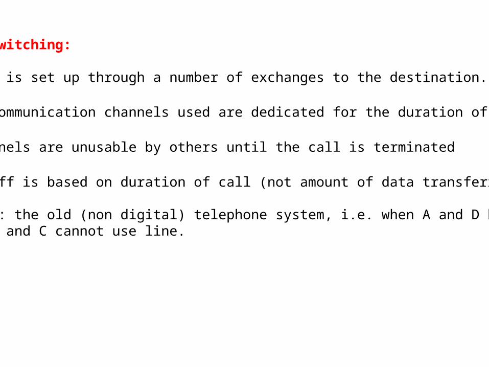
1. Circuit Switching:
• A route is set up through a number of exchanges to the destination.
•the communication channels used are dedicated for the duration of the call
• channels are unusable by others until the call is terminated
• tariff is based on duration of call (not amount of data transferred)
• Example: the old (non digital) telephone system, i.e. when A and D have set up a call B and C cannot use line.
Advantages and disadvantages?

• Advantages:
• Fixed delays• Guaranteed continuous delivery• Secure and dedicated line
• Disadvantages:
• Poor resource utilisation.
• Difficult to support variable data rates.
• Charging is based on duration of call.
• Circuit switching requires a call set-up during which resources are not utilized.
• If messages are much shorter than the call set-up time then circuit switching is not economical (or even Practical)
• More of a problem in high-speed networks

2. Packet Switching:
• Technique used with digital connections to allow multiple calls to exist on same circuit.
• Data broken into small blocks ("packets")
• Packet includes extra information in Header (serial number, destination address...etc).
• Each packet is routed to its destination individually
• Packets re-assembled into original message when destination reached.
• Data tend to be in bursts and charging can be based on the amount of data transferred not duration of call.


3. ADVANTAGES OF PACKET SWITCHING
• Communication channels can support many calls simultaneously.
• Short messages not delayed by long messages.
• More efficient than circuit switching.
DISADVANTAGES
• Performance drops when many users share same network. • Sophisticated protocol architecture needed for data transfer.• Packet can arrive out of order.• variable delay.• packet overhead.
Today the majority of communication systems use packet switching.
Other Technologies? (ATM: cell swiching)

3 The Network Layer:

• The Network Layer manages the virtual link between two host computers.
• The main Functions are:
• splits data into packets
• routes them over the virtual line
• corrects for lost packets
• reassembles packets back into messages
• Layer 1, 2 and 3 are known as communications subnet.
• i.e. separating the pure communications aspects of the network from the higher layers looked after by the hosts.

The design issues of layer 3 are:
• subnet-host interface, i.e. interface between station A and router 1
• routing of packets, i.e. from station A via nodes 1-3-4-7-9-10 to station B
• resolving of congestion and deadlocks.
• opting new routes in case of congestion.
• Load balancing.
• Shortest path.
4. Packet Switching Networks
• The earlier and simpler networks tended to be message switching in that the complete message from layer 4 was sent as a single entity through the subnet.
• Layer 3 of modern complex networks tend to be packet switching:
• message is broken up into a number of packets which are transmitted separately over the subnet.
• a packet is a group of binary bits (including data and control information) that is switched as a whole (the information is arranged in a specified format).
• packet switching data transfer;
• by source and destination address.• Communication channel is occupied for the duration of the transmission only.

4.1 Packet size
• Effect of Packet size; big or small.
• It can be seen that although the amount of data transferred is the same:
• that the smaller the packets the quicker the complete message arrives at the destination.
• if a packet has an error and has to be retransmitted the shorter the packet the better.
• Problem:
• Header overhead.• packets need to be reassembled at destination. • Buffer space needed.


4.2 Packet Switching Services (Virtual Circuit and Datagram)
4.2.1 Virtual Circuit (Connection Oriented):
• Transport layer provide dedicated channel for communication.
• Hence, no errors, messages delivered in same order as supplied.
• Call set up; call set up in the form of Virtual Circuit.
• Data Transfer; all message follow defined route.
• Disconnect; Terminate virtual circuit after data transmission.

4.2.2 Virtual Circuit (Connectionless):
• No Concept of call setup.
• Messages are routed independently from source to destination.
• Hence, sequence of packets can potentially follow different routes through the network.
• each packet must carry the full destination address.
• Problems;
• Lost Packets.• sequence may be Out of order.
• Applicable to short data transfers.
• Transport layer must add error and sequence control.
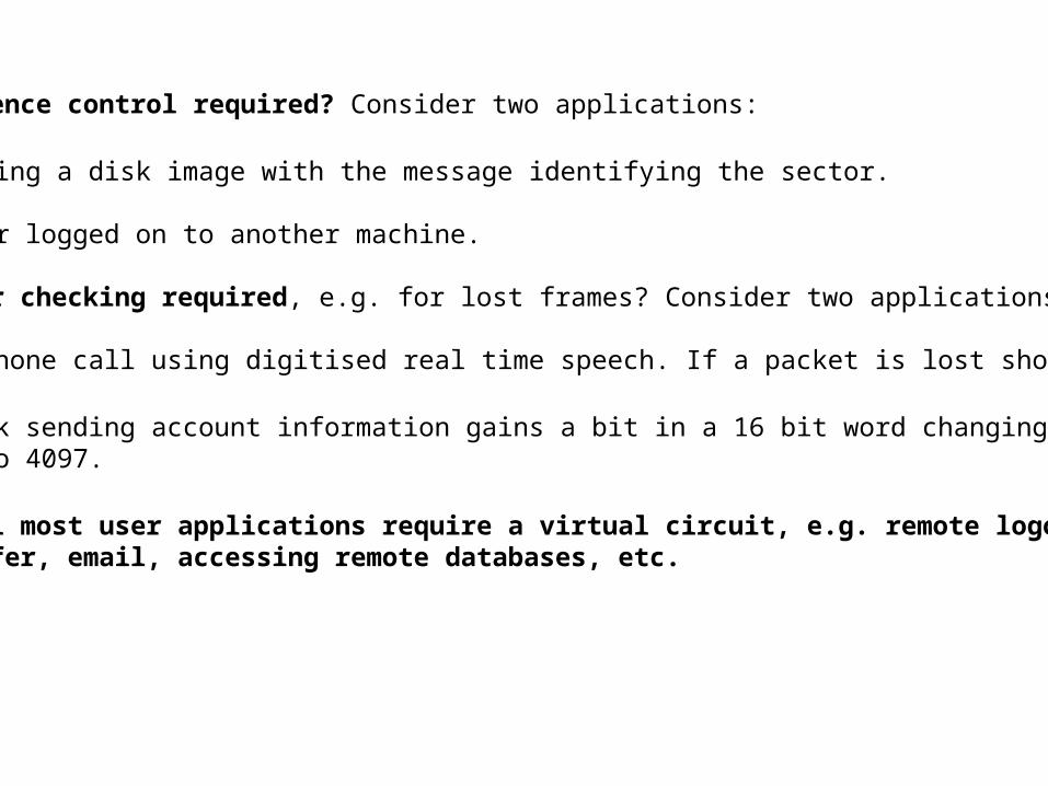
• Is sequence control required? Consider two applications:
• copying a disk image with the message identifying the sector. • user logged on to another machine.
• Is error checking required, e.g. for lost frames? Consider two applications:
• telephone call using digitised real time speech. If a packet is lost should:
• a bank sending account information gains a bit in a 16 bit word changing 1 into 4097.
In general most user applications require a virtual circuit, e.g. remote logon, file transfer, email, accessing remote databases, etc.
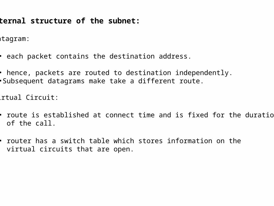
4.3 Internal structure of the subnet:
• Datagram:
• each packet contains the destination address.
• hence, packets are routed to destination independently.•Subsequent datagrams make take a different route.
• Virtual Circuit:
• route is established at connect time and is fixed for the duration of the call.
• router has a switch table which stores information on the virtual circuits that are open.
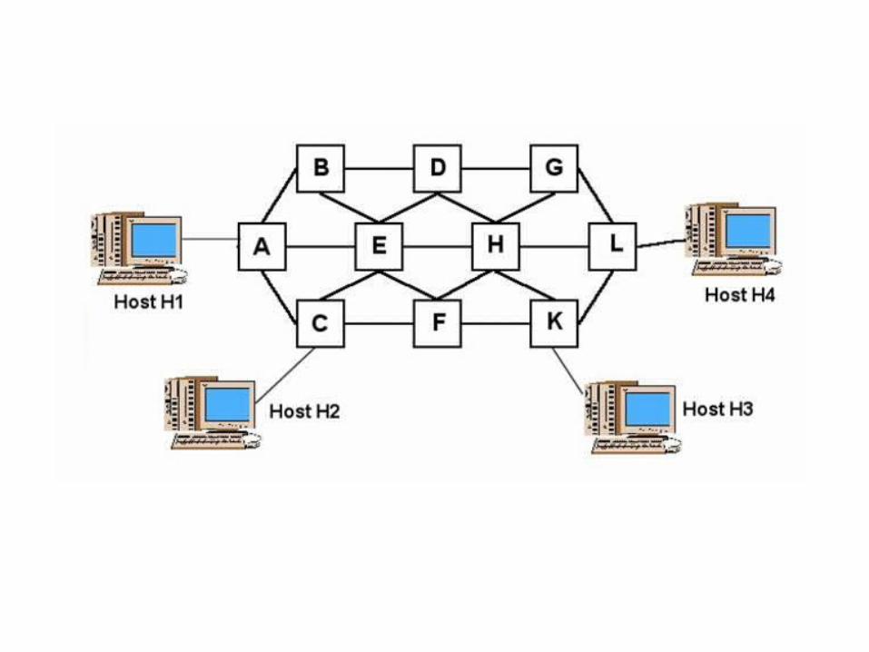
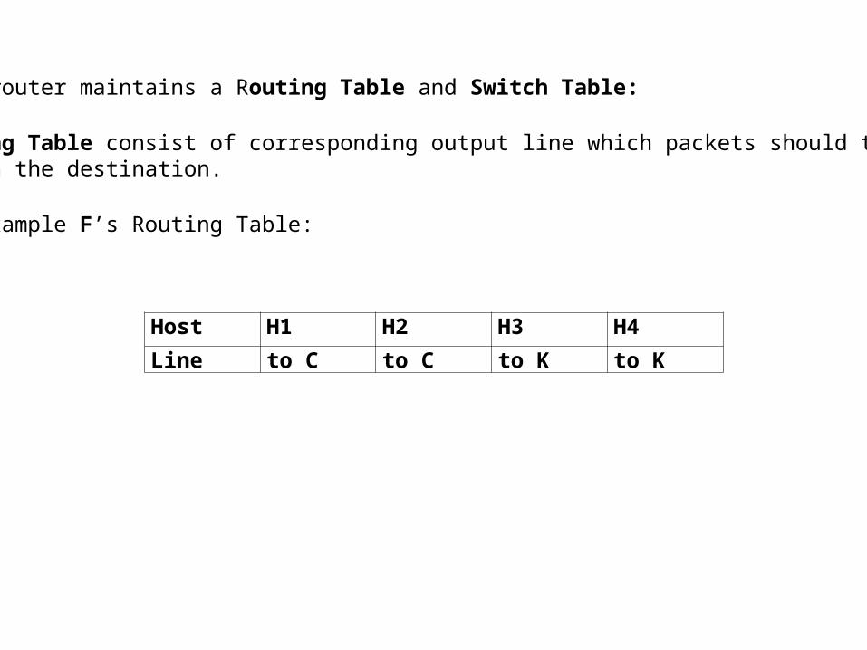
• Each router maintains a Routing Table and Switch Table:
• Routing Table consist of corresponding output line which packets should takes to reach the destination.
• for example F’s Routing Table:
Host H1 H2 H3 H4
Line to C to C to K to K

• Switch Table each entry of which is made up of two tables:
• incoming table: contains entries indicating where the circuit comes from and its number. Associated with each entry is an entry in the outgoing table.
• outgoing table: contains entries indicating the destination of the circuit and its number.
A’s table C’s table F’s table K’s table L’s tableH1 1 C 1 A 1 F 1 C 1 K 1 F 1 L 1 K 1 H4 1
H1 2 C 2 A 2 H2 1
H1 3 C 3 A 3 F 2 C 2 K 2 F 2 H3 1
H2 4 F 3 C 3 K 3 F 3 L 2 K 2 H4 2
H3 2 L 3 K 3 H4 3
• need of switch table?
• When switch table needed (Datagram or VC)?

4.4 Comparison of datagrams and virtual circuits
1.Datagrams contain the full destination address; large overhead with small packets.
2.Virtual circuits require table space in the memory of the hosts and routers
3. For small transactions the overheads of setting up a virtual circuit can be large
4. If traffic conditions change the routes of successive datagrams can change
5.but a virtual circuit is fixed for the duration of the connection.,
i.e. if a router has a ‘traffic jam’ virtual circuit packets will get stuck but datagrams can take alternative routes.

6. Examples:
• Bank cash machine: use datagrams for small individual messages
• File transfer program: use virtual circuits for large amount of error free data
• Video conference:
• Use datagrams: routed individually over fastest route, any error packet thrown away, requires datagrams put into correct sequence at receiver.
• Use virtual circuits: path set up through network so each packet is smaller than datagrams (why?)
• fast transmission• sequencing built in• problem on error when packet is retransmitted

5 Functions of layer-3
• Replies on error free layer 2 transmission of packets and has the following tasks:
• multiplexing – interleaving multiple calls onto one line
• routing – routine packets from source to destination
• flow control – so a fast transmitter does not overload slower receiver
• congestion control

5.1 Multiplexing
• Multiplexing is the interleaving of packets from many virtual circuits onto the layer 2 link.• i.e. a sequence of packets on the layer 2 link would be from different virtual circuits.
5.2 Routing
• In both the setting up of a virtual circuit and the sending of datagrams a route through the network has to be chosen.
• Desired properties of routing algorithms are:
• correctness: the destination is correct
• simplicity: for speed, low cost, etc.
• robustness: if an router or line fails or there is a traffic jam the whole network should not crash

• stability: some algorithms may never yield a route
• fairness: to ensure that all users get a fair shore of the network
• optimality: depends on the property to be optimised:
• minimise packet delay
• maximise network throughput
• Shortest Path (e.g. OSPF)
5.2.1 Routing algorithms
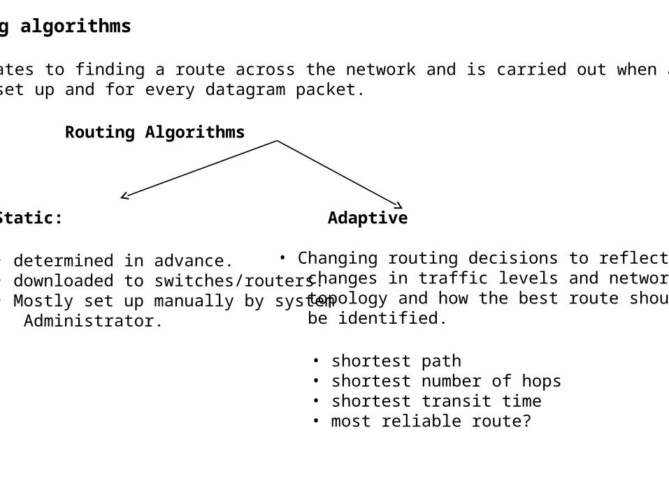
• Routing relates to finding a route across the network and is carried out when a virtual circuit is set up and for every datagram packet.
Routing Algorithms
Static:
• determined in advance.• downloaded to switches/routers.• Mostly set up manually by system Administrator.
Adaptive
• Changing routing decisions to reflect changes in traffic levels and network topology and how the best route should be identified.
• shortest path• shortest number of hops• shortest transit time• most reliable route?

5.2.1 Routing algorithms
• Flooding Algorithms.
• Static Routing Algorithms.
• Central Routing.
• Isolated Routing.
• Hot Potato Algorithm.
• Backward Learning Algorithm.
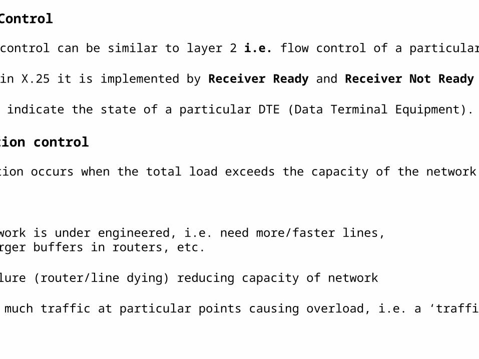
5.3 Flow Control
• Flow control can be similar to layer 2 i.e. flow control of a particular call
• e.g. in X.25 it is implemented by Receiver Ready and Receiver Not Ready packets
• which indicate the state of a particular DTE (Data Terminal Equipment).
5.4 Congestion control
• Congestion occurs when the total load exceeds the capacity of the network.
• Causes:
• Network is under engineered, i.e. need more/faster lines, larger buffers in routers, etc.
• failure (router/line dying) reducing capacity of network
• too much traffic at particular points causing overload, i.e. a ‘traffic jam’
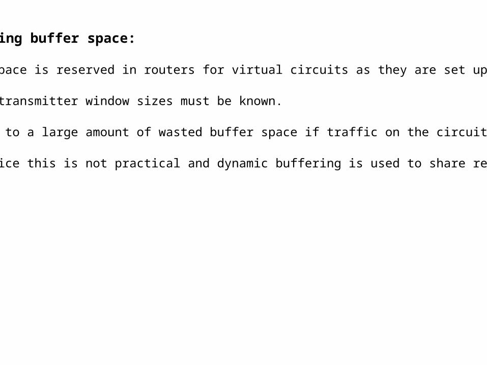
5.4.1 Reserving buffer space:
• Buffer space is reserved in routers for virtual circuits as they are set up.
• Maximum transmitter window sizes must be known.
• can lead to a large amount of wasted buffer space if traffic on the circuits is low.
• In practice this is not practical and dynamic buffering is used to share resources.
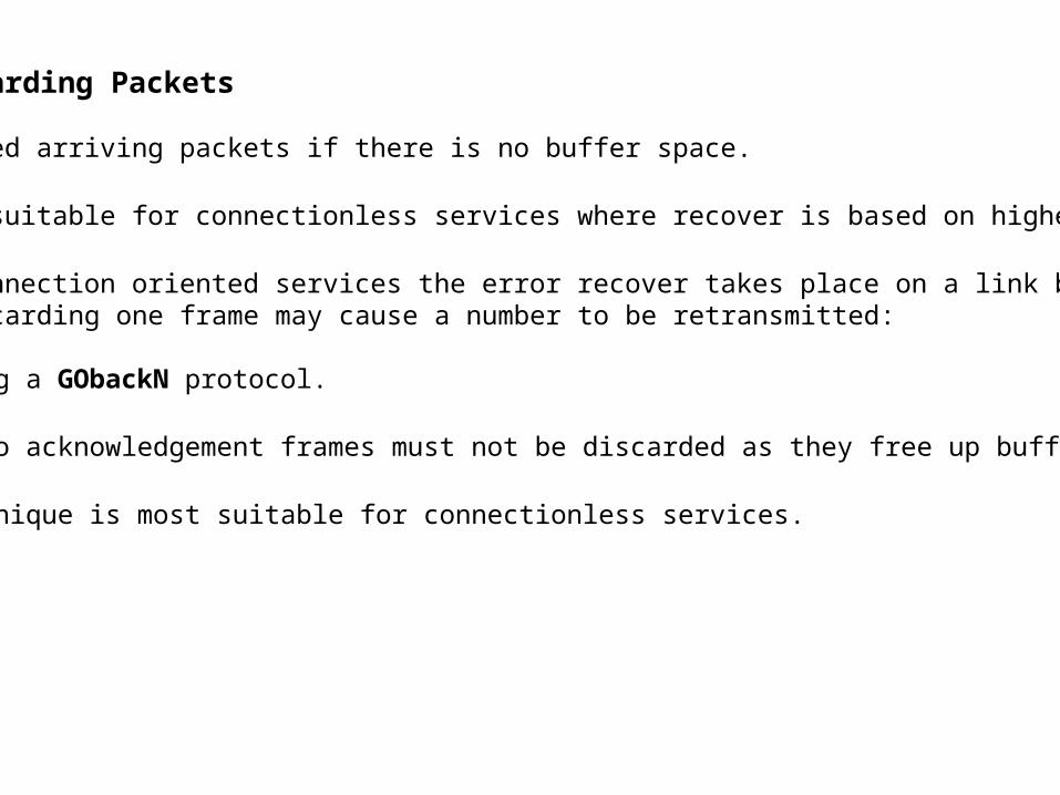
5.4.2. Discarding Packets
• Discarded arriving packets if there is no buffer space.
• Hence, suitable for connectionless services where recover is based on higher layers.
• With connection oriented services the error recover takes place on a link by link basis and discarding one frame may cause a number to be retransmitted:
• Using a GObackN protocol.
• Also acknowledgement frames must not be discarded as they free up buffer space.
• Technique is most suitable for connectionless services.

5.4.3 Use of tokens
• Tokens can be used to control number of packets in network.
• Data Transmission Sequence:
• Capture a token.
• when a packet arrives at a destination the token must be released.
• Thus the number of packets in the network is kept constant.
• There are problems:
• there may be free tokens in the network but may not be where nodes wish to transmit
• there is no method of regenerating lost tokens
• It is not very robust and is equally unsuited for connectionless and connection oriented networks.

5.4.4 Adaptive windowing
• Network nodes can send congestion information to hosts to control their window size.
• i.e. reducing window size reduces the number of packets that can be transmitted.
• problems are:
• time for message to get to hosts.
• deciding when to send the information.
• deciding which calls it should apply to.
• not knowing if the host has responded to the information.
• However, a useful technique for connectionless and connection oriented networks.

6 CCITT X25 for packet switching networks
• Terminology:
DTE Data Terminal Equipment is the user computer or terminal which is linked to a DCE.
DCE Data Circuit Terminating Equipment which provides the interface to the network
PAD Packet Assembly/Disassembly Interface enables dumb terminals or PCs to link to an X25 networks via an RSR232 serial interface.


6.1 X25 routing – see TCP/IP notes for IP datagram routing • X25: Used in WANS which employ packet switched public facilities.•e.g. PSDN, to pass data between different sites
• Function: Defines the nature of the various packets needed to set up and maintain a connection between a DTE and a switched network.
• Mechanism: Virtual Circuit
•How does it work?
• 3 stages:
a) Set up the call b) Send data and maintain the connection for the duration of the call. c) Close down the call.

1. Setting up the call:
• calling DTE issues a CALL REQUEST packet.
• a local logical channel number (LCN) is assigned for this call and is written into the CALL REQUEST packet.
• each switch has a switch table with input and output columns.
Input OutputLink LCN Next hop New LCN

• When CALL REQUEST packet is sent to a switch:
• Routing table is used to select the best link onwards from this switch.
• A free local LCN is assigned.
• This information is then written into the switch table
• Each switch, from source to destination, will contain an entry in its switch table to define the next part of the route for all packets relating to this call.
• i.e. the route is established.

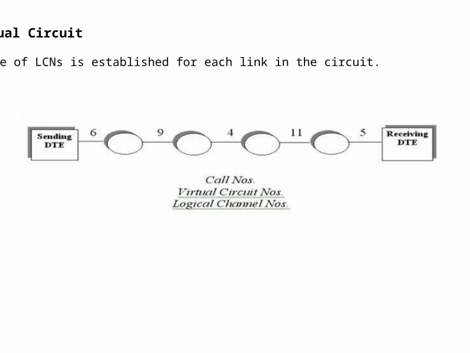
Virtual Circuit A range of LCNs is established for each link in the circuit.
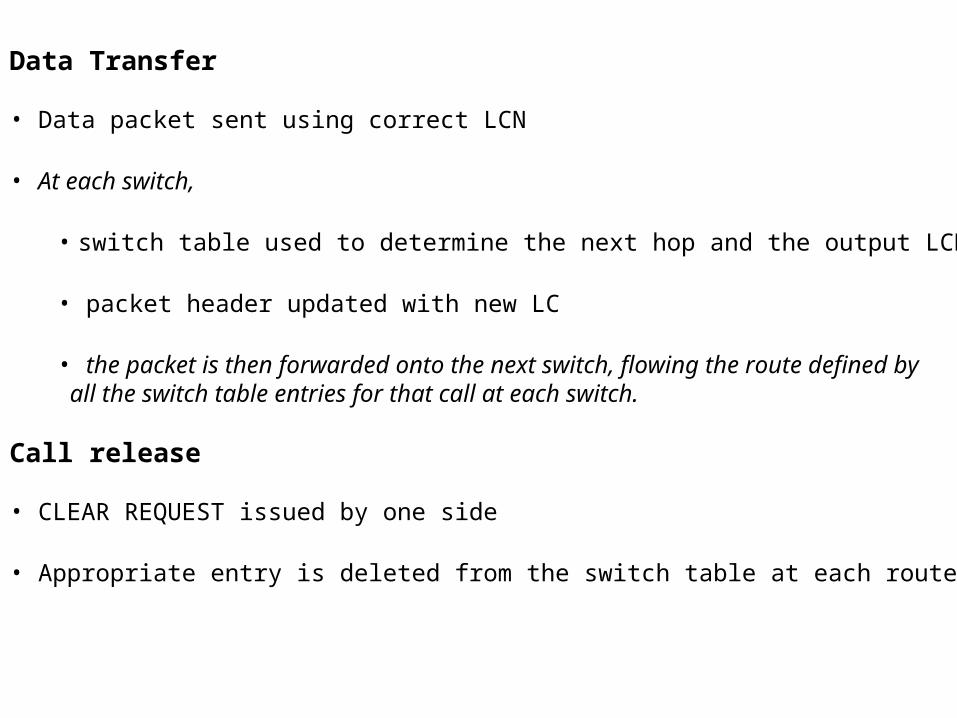
2. Data Transfer
• Data packet sent using correct LCN
• At each switch,
• switch table used to determine the next hop and the output LCN
• packet header updated with new LC
• the packet is then forwarded onto the next switch, flowing the route defined by all the switch table entries for that call at each switch.
3. Call release
• CLEAR REQUEST issued by one side
• Appropriate entry is deleted from the switch table at each router
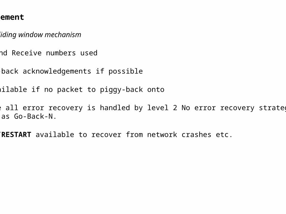
Call Management
• Uses a sliding window mechanism
• Send and Receive numbers used
• Piggy-back acknowledgements if possible
• RR available if no packet to piggy-back onto
• Assume all error recovery is handled by level 2 No error recovery strategy such as Go-Back-N.
• RESET/RESTART available to recover from network crashes etc.
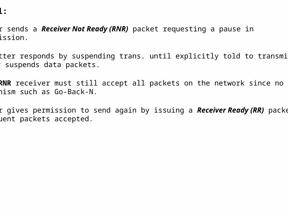
Flow Control:
• Receiver sends a Receiver Not Ready (RNR) packet requesting a pause in transmission.
• Transmitter responds by suspending trans. until explicitly told to transmit again. RNR only suspends data packets.
• After RNR receiver must still accept all packets on the network since no recovery mechanism such as Go-Back-N.
• Receiver gives permission to send again by issuing a Receiver Ready (RR) packet. Subsequent packets accepted.
Related Documents