VOLUME 23, 1961/62, No. n pp. 325-364 Published 12 tb September 1962 Philips Technical Review DEALING WITH TECHNICAL PROBLEMS RELATING TO THE PRODUCTS, PROCESSES AND INVESTIGATIONS OF THE PHILIPS INDUSTRIES I THE NEUTRON TUBE, A SIMPLE AND COMPACT NEUTRON SOURCE by O. REIFENSCHWEILER *) and K. NIENHUIS **). 621.387:539.125.5 In recent years the rapid expansion of nuclear physics and its practical applications, and the central role of the neutron in that branch of physics, have occasioned a wide demand for neutron sources. A great variety of neutron sources and generators exists, but no simple, compact, transportable type generating fast, monochromatic neutrons has been available until now. The present article deals with a sealed neutron tube that fills this gap. In some details of design and operatioti it resembles an X-ray tube, and it is capable of providing a continuous output of at least lOB neutrons per second. It is interesting to note that F. lIf. Penning, whose name is familiar in connection with the vacuum gauge he invented, built an experimental neutron tube as long ago as 1937, but did not folloui up this line of development. The rapid expansion of nuclear physics is due in great measure to the research into the proper- ties of the neutron and into its interaction with matter that has been conducted all over the world, with more and more elaborate equipment, ever since this elementary particle was first discovered in 1932. So important are the applications of nuclear physics developed in recent decades that a new discipline, nuclear engineering, has come upon the scene; here too, the neutron may be said to take a central position. In a nuclear reactor the neutron is the agent that causes fission and transmits the fission reaction from one nucleus to another and, in virtue of this chain of reactions, liberates energy. Neutrons can be used to produce many of the radio- active isotopes needed as tracer elements in the study of industrial, chemicalor biological processes. Crystal structures and the properties of materials can be investigated by means of neutrons, and there are many further uses for these particles. Inquiry into the properties of neutrons, and experimental work with the aid of neutrons, are therefore important aspects nowadays of research in many fields; this kind of work invariably calls for neutron sources. The present article describes the general make-up and functioning of a sealed-off *) Philips Research Laboratories, Eindhoven . .... ) Electron Tubes Division, Philips, Eindhoven. neutron source which in construction and operation resembles an X-ray tube. The development of the neutron tube in the Philips Research Laboratories 1) can be regarded as a resumption ofthe work of F. M. Penning 2) in 1937; in the last few years the devel- opment has reached the stage at which, in co- operation with the Electron Tubes Division, it was ripe for quantity production. Its potential applications are reviewed at the end of the article. Nuclear reactions yielding neutrons; neutron sources Since, in general, neutrons exist only as compo- nent parts of atomic nuclei they can only be freed by way of nuclear reactions. Essentially, then, neutron sources are devices for staging suitable nuclear reac- tions. A beam of fast, lightweight nuclei (protons, deuterons or a particles) can be used for this purpose. Nuclei must be brought into close proximity if they are to react. This means overcoming the repulsion between the nuclei due to their electrical charges 1) An earlier stage of this work was reported on at the Deutsche Physikertagung 1957, held in Heidelberg. SeeO. Reifenschweiler and A. C. van Dorsten, Eine abgeschmol- zene. Neutronenröhre, Phys. Verh. (Mosbach) 8,163,1957. For in extenso treatment of all the problems and their solution, see O. Reifenschweiler, Philips Res. Repts 16, 401-418, 1961 (No. 5). See also Nucleonics 18, No. 12, 69-71, 1960. 2) F. M. Penning and J. H. A. Moubis, Eine Neutronenröhre ohne Pumpvorrichtung, Physica 4, 1190-1199, 1937.

Welcome message from author
This document is posted to help you gain knowledge. Please leave a comment to let me know what you think about it! Share it to your friends and learn new things together.
Transcript
VOLUME 23, 1961/62, No. n pp. 325-364 Published 12 tb September 1962
Philips Technical ReviewDEALING WITH TECHNICAL PROBLEMS
RELATING TO THE PRODUCTS, PROCESSES AND INVESTIGATIONS OF
THE PHILIPS INDUSTRIES
I
THE NEUTRON TUBE, A SIMPLE AND COMPACT NEUTRON SOURCE
by O. REIFENSCHWEILER *) and K. NIENHUIS **). 621.387:539.125.5
In recent years the rapid expansion of nuclear physics and its practical applications, and thecentral role of the neutron in that branch of physics, have occasioned a wide demand for neutronsources. A great variety of neutron sources and generators exists, but no simple, compact,transportable type generating fast, monochromatic neutrons has been available until now.The present article deals with a sealed neutron tube that fills this gap. In some details of designand operatioti it resembles an X-ray tube, and it is capable of providing a continuous output ofat least lOB neutrons per second. It is interesting to note that F. lIf. Penning, whose name isfamiliar in connection with the vacuum gauge he invented, built an experimental neutrontube as long ago as 1937, but did not folloui up this line of development.
The rapid expansion of nuclear physics is duein great measure to the research into the proper-ties of the neutron and into its interaction withmatter that has been conducted all over the world,with more and more elaborate equipment, eversince this elementary particle was first discovered in1932. So important are the applications of nuclearphysics developed in recent decades that a newdiscipline, nuclear engineering, has come upon thescene; here too, the neutron may be said to take acentral position. In a nuclear reactor the neutronis the agent that causes fission and transmits thefission reaction from one nucleus to another and, invirtue of this chain of reactions, liberates energy.Neutrons can be used to produce many of the radio-active isotopes needed as tracer elements in thestudy of industrial, chemicalor biological processes.Crystal structures and the properties of materialscan be investigated by means of neutrons, and thereare many further uses for these particles.Inquiry into the properties of neutrons, and
experimental work with the aid of neutrons, aretherefore important aspects nowadays of researchin many fields; this kind of work invariably callsfor neutron sources. The present article describes thegeneral make-up and functioning of a sealed-off
*) Philips Research Laboratories, Eindhoven .....) Electron Tubes Division, Philips, Eindhoven.
neutron source which in construction and operationresembles an X-ray tube. The development of theneutron tube in the Philips Research Laboratories 1)can be regarded as a resumption ofthe work of F. M.Penning 2) in 1937; in the last few years the devel-opment has reached the stage at which, in co-operation with the Electron Tubes Division, itwas ripe for quantity production. Its potentialapplications are reviewed at the end of the article.
Nuclear reactions yielding neutrons; neutron sources
Since, in general, neutrons exist only as compo-nent parts of atomic nuclei they can only be freed byway of nuclear reactions. Essentially, then, neutronsources are devices for staging suitable nuclear reac-tions. A beam of fast, lightweight nuclei (protons,deuterons or a particles) can be used for this purpose.Nuclei must be brought into close proximity if theyare to react. This means overcoming the repulsionbetween the nuclei due to their electrical charges
1) An earlier stage of this work was reported on at theDeutsche Physikertagung 1957, held in Heidelberg. SeeO.Reifenschweiler and A. C. van Dorsten, Eine abgeschmol-zene. Neutronenröhre, Phys. Verh. (Mosbach) 8,163,1957.For in extenso treatment of all the problems and theirsolution, see O. Reifenschweiler, Philips Res. Repts 16,401-418, 1961 (No. 5). See also Nucleonics 18, No. 12,69-71, 1960.
2) F. M. Penning and J. H. A. Moubis, Eine Neutronenröhreohne Pumpvorrichtung, Physica 4, 1190-1199, 1937.
326 PHILIPS TECHNICAL REVIEW VOLUME 23
(Coulomb field); their velocity relative to each othermust therefore be high. The relative velocity andhence the kinetic energy the particles must have aredependent on the reaction it is desired to bringabout.Three of the many types of neutron-yielding
nuclear reactions may be cited here, Firstly, beryl-lium enters with an a particle into the reaction9Be(a, n)12Cor, in the more detailed notation:
!Be + ~He--+ I~C+ ~n+ 5.65 MeV. (1)
Secondly, deuterium reacts with deuterium; knownas the D-D reaction, this is written D(d,n)3He, or, inthe extended notation,
iH + iH--+ ~He + ~n+ 3.26 MeV. (2)
Thirdly, the so-called D-T reaction, between deuter-ium and tritium, is written T(d,n)4He or
~H+ iH--+ ~He + ~n+ 17.6 MeV. (3)
In order to bring about any of these reactions it isnecessary to give one of the partners a high kineticenergy and cause it to collide with the other partner.The energy of the incident particle plus the energyliberated by the reaction, as specified in the aboveequations, is shared between the two products ofthe reaction in accordance with the principlesof conservation of energy and momentum. Theneutron acquires most energy when it is emitted inthe forward direction; when emitted in any otherdirection it acquires a smaller amount dependent onthe angle it makes with the direction of motion ofthe incident particle, and on the initial energy of thisparticle. It is possible by collimation to obtain abeam of monoenergetic neutrons.
Reaction (1) above can easily he induced: all thatis necessary is to bring a radioactive substanceemitting alpha particles, radium or polonium forexample, into proximity with beryllium. It was inthis way that the neutron was discovered in the firstplace. Accordingly, the simplest neutron sources,which are also the oldest, consist of a mixture ofpowdered beryllium and (say) radium enclosed in acapsule. Various other combinations of a-emittersand neutron-yielding elements are in use.Neutron sources embodying radioactive sub-
stances are simple in design and small in size, therate at which they emit neutrons is virtually con-stant, and they are usually long-lived; neverthelessthey have certain drawbacks as compared withother kinds of source. For one thing the neutronssupplied have a complex energy spectrum, and thisis often undesirable in experimental work. Sometypes of radioactive neutron source are associated
with a strong background of y-radiation; a Ra-Besource, for example, emits about 104 y-quanta perneutron. The neutron flux cannot be varied and it istherefore impossible to pulse the neutrons, though inmany experiments a pulsed neutron supply isdesirable. The source cannot be switched off, andconsequently careful shielding is necessary evenwhen it is not in use. The financial outlay climbs sosteeply with the power of the source that for fluxesexceeding 107 neutrons/sec, other types of source arepreferable.There is no natural particulate radiation suitable
for inducing reactions (2) and (3) or other nuclearreactions falling into the same category; the par-ticles constituting one of the two partners in thereaction must therefore he artificially accelerated upto a high velocity. It is on this principle that thetube described here is based. Since 1932, the year inwhich Cockcroft and Walton did their pioneeringexperiments with artificially accelerated particles,the technique of using such beams to induce nuclearreactions has been developed to a high level ofefficiency. Though exhibiting certain essential
I
~p
7368
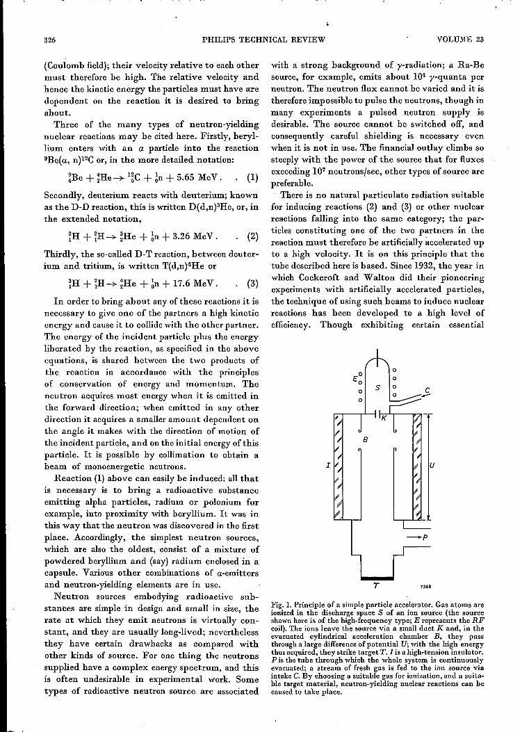
Fig. 1.Principle of a simple particle accelerator. Gas atoms areionized in the discharge space S of an ion source (the sourceshownhere is of the high-frequency type; E represents the RFcoil).The ions leave the source via a small duct K and, in theevacuated cylindrical acceleration chamber B, they passthrough a large difference ofpotential U;with the high energythus acquired, they strike target T. I is a high-tension insulator.P is the tube through which the whole system is continuouslyevacuated; a stream of fresh gas is fed to the ion source viaintake C.By choosing a suitable gas for ionization, and a suita-ble target material, neutron-yielding nuclear reactions can becaused to take place.
1961j62, No. 11 NEUTRON TUBE 327
differences, our neutron tube shares many featureswith a particle accelerator and for that reason itwill be as well to devote a little time to the principleof the latter (fig. 1). Gas molecules are convertedinto ions in an ion source S. Via K, a narrow cylin-drical duct, some of the ions enter the evacuatedcylindrical acceleration chamber B where they fallthrough a large potential difference U; having thusacquired a high kinetic energy, they strike an elec-trode of suitable material, the target T (usuallyearthed), with which they enter into a neutron-yielding nuclear reaction. The ancillary apparatusincludes, apart from a high-tension generator,various devices omitted from fig. 1 for the sake ofsimplicity - namely, an HF generator for the ionsource, with power supply unit, a complete vacuumsystem embodying backing and high-vacuum pumpsand cold traps, and a gas storage and supply system,with a sensitive control valve, for the ion source.Though free of the drawbacks of the type con-taining radioactive substances, accelerator-typeneutron sources are generally very large and ex-pensive installations that often have to be housedin a separate building 3) (see also the photographon page 341 ofthis issue).In recent years there have been various attempts
to build compact and, if possible, transportableversions of these accelerator-type neutron-gener-ating equipments. On the basis of reaction (3)above, these compact generators have become apractical possibility mainly in consequence of theavailability of tritium in adequate quantities. Now-adays this isotope ofhydrogen can be produced fromlithium in nuclear reactors, using the reaction6Li(n,a)3H. Reaction (3) shows that with tritium asthe target nucleus, a fairly high neutron yield isobtained even when the voltage accelerating thebombarding deuterons (i.e. deuterium ions) isrelatively low (60 kV for example). The effectivecross-section for the D-T reaction exhibits a peak atthe unusually low energy of 107 keV. In virtue ofall this it has been possible to build neutron gener-ators which, while still rather complicated indesign, and necessarily including a complete vacuumsystem, can be mounted on trolleys and so movedfrom place to place.While enumerating the various types of neutron source
and generator we must not neglect to mention that nuclearreactors are nowadays the biggest-scale producers of neutrons 4).
3) See for example A. C. van Dorsten and J. H. Spaa, A highoutput D-D neutron generator for biological research,Nuci. Instr. 1, 259-267, 1957, or Philips tech. Rev. 17,109-111, 1955/56.
4) A reference to the use of a nuclear reactor as a neutronsource may be found in J. Goedkoop,Neutron diffraction,.Philips tech. Rev. 23, 69-82, 1961/62 (No. 3).
The reaction taking place in these is of a different nature fromthose ofreactions (1) - (3), namely nuclearfission. As a result ofbombardment with neutrons, and also to some extent as aresult of slow neutron capture, certain nuclei (233U,235Uand23DPU)can be caused to split and to release further neutrons, aseries of these neutron-yielding reactions thus being initiated, Asmall proportion of the neutrons can be extracted via a duct inthe shield of the reactor without prejudice to the continuityof the process. For many applications requiring a high neutronflux, a better source than a nuclear reactor is hardly likely tobe found. Yet such big, complicated and costly installationsare of course available only in a limited number; in practice,therefore, their usefnlness as neutron sources is limited.Also a transportable neutron source in the form of a nuclearreactor is probably not a practical possibility.
There is a third category of neutron-yielding nuclear reac-tions which should be mentioned here for the sake of complete-ness; "photonuclear" reactions occur when nuclei are exposedto high-energy y-radiation. In neutron sources working on thisprinciple, the y-radiation is either obtained from a radioactivesubstance - this type has the same disadvantages as the radio-active sourcesdiscussed above - or produced in a largeparticleaccelerator with the aforementioned drawbacks of complicateddesign and high cost.It may be noted in passing that scientific resources are cur-
rently being lavished on attempts to realize a further theoreti-cal possibility, namely that of using the thermal energy ofgases and plasmus at extremely high temperatures in order toinduce nuclearfusion. A "fusion reactor", if it were ever built,would be a particularly rich source of fast neutrons.
A big advance in the direction of a compact,straightforward, monoenergetic neutron source wasmade with the development of an accelerator-typeneutron generator in the form of a sealed tube; theneed for a pumping arrangement and a continuoussupply of gas for the ion source thus being eliminated.The Philips neutron tube 5), based on this principleand under development since 1955, is shown in fig. 2;its general construction is shown in fig. 3. The tubebears a certain family resemblance to an X-ray tube;it has been possible in virtue of this to make use ofaccumulated experience in X-raytube design, partic-ularly in the matter of high-tension insulation andthe prevention of arcing. However, in regard to theprinciple on which it works, the neutron tube is adirect descendant of the conventional particle accel-erator (fig. I). It accordingly displays the sameessential structural features - an ion source, acceler-ating electrodes and a target that, bombarded by theaccelerated ions, emits neutrons in virtue ofthe D-Treaction (3). The yield is in excess of 10Bneutrons/sec.
5) In the meantime neutron generator tubes have been de-scrihed by other authors: J. D. Gow and H. C.Pollock,Rev.sci. Instr. 31, 235-240, 1960. P. O. Hawkins and R.W. Sutton, Rev. sci. Instr. 31, 241-248, 1960. A. H.Frentrop and H. Sherman, Nucleonics 18, No. 12, 72-74,1960. B. J. Carr, Nucleonics 18, No. 12, 75-76, 1960..
328 PHILlPS TECHNICAL REVIEW
7367
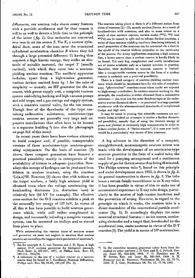
Fig. 2. The Philips neutron tuhe (at hottom in photo). The left-hand end of the tube, con-taining the ion source and a hydrogen pressure regulator, is at earth poten tial. High tensionis applied to the right-hand end, via a HT cable and p.lug (cen tre). The tube as delivered (top)is encloscd in a metal cylinder with all outer diameter of7 cm. Thiscylindrical sheath, which isearthed, affords mechanical protection and holds the HT insulation in place around thetube; it does not present ally appreciable obstacle to the neutrons issuing from the target.These are expelled in all directions, but normal practice is to use only those with directionsperpendicular to the tube axis.
One mmor difference from a particle accelerator isthat the high tension is applied to the target andthe ion source is earthed; this arrangement offerscertain operational advantages.In the next section we shall deal with three main
problems presented by the design of the neutrontube and explain how we have solved t.hern.
The neutron tuhe: fundamental problems and theirsolution
A characteristic of accelerator-type neutronsources of the type shown in fig. lis that the parti-cles to be accelerated are produced in a chamber inwhich a relatively high pressure prevails (of the
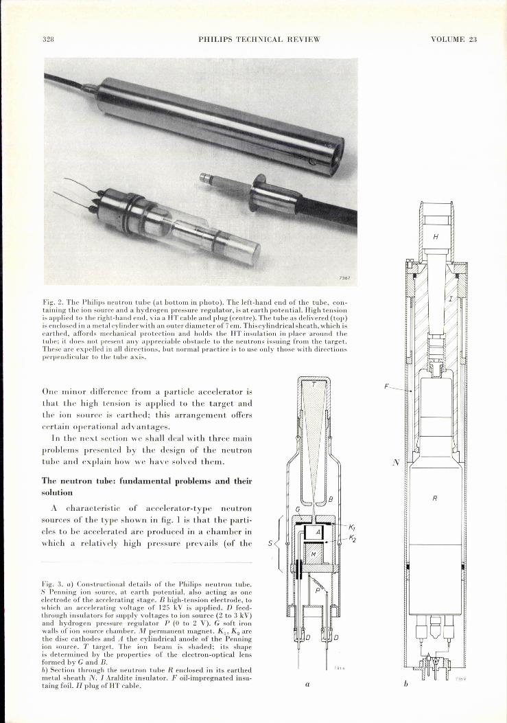
Fig. 3. a) Constructional details of the Philips neutron tube.S Penning ion source, at earth potential, also acting as oneelectrode of the accelerating stage. B high-rension electrode, towhich an accelerating voltage of 125 kV is applied. D feed-through insulators for supply voltages to ion source (2 to 3 kV)and hydrogen pressure regulator P (0 to 2 V). G soft ironwalls of ion source chamber. M permanent magnet. Kl' K2 arethe disc cathodes and A the cylindrical anode of the Penningion source. T target. The ion beam is shaded; its shapeis determined by the properties of the electron-optical lensformed by G and B.b) Section through the neutron tube R enclosed in its earthedmetal sheath N. I Araldite insulator. Foil-impregnated insu-taing foil. H plug of HT cable.
T
5
o o
7818
a
VOLUME 23
F
N
R

1961/62, No. 11 NEUTRON TUBE . 329
order of 10-2 torr) whereas acceleration takes placein a space under relatively low pressure (of the orderof 10-5 torr). The pressure difference between ionsource and acceleration space is maintained by con-tinuously feeding gas into the former (via inlet C)and continuously evacuating the latter by means ofa high-vacuum pump. Now, in a sealed neutron tubethis continuous gas How must be dispensed with,and so in consequence must the pressure differencebetween the ion source and the accelerating space.Thus the first problem involved by a sealed
neutron tube is that of designing an ion source andan accelerating system that will work at the samegas pressure. If an intermediate pressure value isdecided on, then the gas discharge in the ion sourcemust sustain itself at a relatively low pressure and ata voltage that is not unduly high; the implication forthe accelerating stage is that no discharge or Hash-over must take place between the accelerating elec-trodes despite the high voltages these are required tocarry, and despite the relatively high pressureprevailing.
A second problem, likewise connected with theabsence of a stream of gas through the tube, is thatof gas clean-up as a result of the discharge. In asealed tube this effect involves a rapid fall-off inpressure. Some expedient must therefore be foundfor keeping the gas pressure during operation con-stant throughout its useful life.
A third problem inherent in a sealed neutron tubeis that of target life. Tritium targets of the typecommonly used hitherto (in tubes exploiting theD-T reaction) have only a limited life, shorter than isgenerally desirable in a sealed tube. Obviously therecan be no question, in such a tube, of replacingthe target at intervals, as is possible in pumpedneutron generators.
The ion source
The first of the problems referred to above - thatof finding an ion source that will work at lowpressures - can be solved by recourse to a deviceknown for twenty-five years. It was precisely thefact that the Penning ion source could function at arelatively low pressure that led its inventor todesign a sealed neutron tube 2). As in other ionsources, the ions are produced in a gas discharge, i.e.mainly by the impact of electrons. For this it isnecessary that the mean free path of the electronsshould be smaller than the distance available forthem to travel through. Now, in other ion sourcesthis distance is of the same order as the dimensionsof the discharge chamber, and consequently themean free path must be small and, generally speak-
ing~ the pressure must be in excess or' 10-2 torr; thePenning ion source is so designed that the averagedistance travelled by the electrons is many hundredtimes greater than the electrode separation. This isachieved by using a special electrode layout andintroducing a magnetic field. In these circumstances,then, there is still plenty of chance of ion formationby electrons with a large mean free path; it is there-fore possible for the source to work at a lowerpressure (10-3 to 10-4 torr).
A further virtue of the Penning ion source is itssimplicity. No heated filamentary cathode is used:the discharge is sustained by electrons released fromcathode plates by ion impact and by the photo-elec-tric effect; accordingly, only one DC supply of about2 kV is required for the ion source.
Fig. 4 is a schematic cross-section through thePenning type ion source incorporated in our neutrontube 1). A cylindrical anode A lies between two disc-shaped cathodes Kl and K2• A direct voltage of 2 to3 kV is applied between the anode and the cathodes.In the resulting discharge, electrons oscillate be-tween the cathodes many times before finallystriking the anode, being forced into helical paths bythe magnetic field. The ions created by collisionsbetween electrons and gas atoms move towards thecathodes. Some are able to quit the ion source cham-ber through an opening in cathode Kl' The mag-
7370
Fig. 4. Schematic cross-section of the ion source incorporatedin the Philips neutron tube. G walls of ion source chamber. Ais the anode, Kl and Kz the cathodes of the Penning electrodesystem. M permanent magnet. The broken lines representmagnetic lines of force; the magnetic circnit is completed bythe soft iron wallsG of the ion source chamber. Z direction ofion beam leaving the chamber. rp is the electrical potentialas a function of the distance z alang the axis of the tube;the electrons sustaining the discharge swing back and forthin the resulting potential well between the cathodes (seediagram) and are forced by the magnetic field into helicalpaths. The distance travelled by the electrons is thus manytimes greater than the geometrical electrode separation. It isfor this reason that the discharge can sustain itself at gaspressures as low as 10-3 torr.

330 PHILlPS TECHNICAL REVIEW VOLUME 23
netic field is brought about by a small permanentmagnet M which is accommodated inside the cham-ber. The walls of the chamber G are of soft iron, and soserve to complete the magnetic circuit and to screenthe neighbouring acceleration space from the mag-netic field in the ion source. This is important from thestandpoint offreedom from high-voltage breakdownin the acceleration space, since a magnetic field in-creases the chance of ionization by electrons and solowers the striking voltage for a self-sustainingdischarge. This fact is exploited in the ion sourceitself, but just the opposite desiderata are relevantto the acceleration space.
The Penning ion source has a certain drawback inthat it mainly supplies singly-charged molecularions (H2 + with hydrogen as filler gas, D2+ withdeuterium) in the range of pressures of interest. Thiswe discovered at the outset, in 1956, when the ionbeam was submitted to mass-spectrometric analysisin our Research Laboratories (fig. 5). For a givendischarge current, the number of atoms in a beamof singly-ionized diatomic molecules is twice as largeas that in a beam of monatomic ions. Moreover, eachof the two atoms in the ionized molecule acquires onlyhalf of the total energy, so that in a neutron tubeoperated at 125kV, only 62.5 keV ofprimary energyis available for the nuclear reaction. Since in thisrange of energies the probability of the reactiontaking place diminishes sharply with decreasingvoltage, the final result is that the neutron yield islower than it would be with a beam of monatomicions. This drawback of the Penning ion source hasbeen accepted in view of the far greater importanceattached to its advantages - long life, robustness,and simplicity of construction and operation.
100%
90
80
7060
50
40
30
20
10
o10-3 2
H+ H+ X- 2 - ~ Ht <iJ
\ H; 0
d
~.0
I\
R 1-~
I.- ...-~)(
)( ~)( ..... ,'1- .....j • .r.>-)( T1j3 --0• _ ...... -
5 10-2 2 5 10-' torr----p 7371
Fig. 5. Composition of the beam of hydrogen ions produced by aPenning ion source, as a function of pressure. In the range be-tween 10-3 and 3X 10⁻² torr the beam mainly consists of mole-cular (H2+) ions.
Arrangements for feeding in the direct-voltagesupply are greatly simplified by the fact that the ionsource is at earth potential.
The 125-k V acceleration stage
Conventional accelerators working in conjunctionwith a pump operate at pressures lower than 10-4torr, and acceleration generally takes place in severalstages. Preliminary experiments 1) revealed that a200 kV acceleration system, to operate at pressuresup to 2X10⁻² torr, could be designed as a singlestage. The electrode separation in these experimentswas about 1 cm. Accordingly, no design difficultieswould he involved by a neutron tube operating at apressure of 10-3 torr and an accelerating voltage of125 kV. Itwould, however, be necessary to give theelectrodes a high polish, since otherwise there wouldbe a risk of field emission from the negative elec-trode. Accelerating electrodes for the neutron tubedescribed here are made of chrome steel which, asexperience with X-ray tubes has shown, exhibitsvery little liability to field emission.
As will be clear from the sketches in fig. 3, acceler-ating electrode B has an opening through which theion beam enters the field-free space inside the elec-trode. The beam is conical in shape, its apex anglebeing determined by the properties of the electron-optical lens formed by the ion source and accele-rating electrode. Fig. 6 is a photograph of the ionbeam in an experimental tube. In the final version ofthe neutron tube, as developed on the basis offindings from these experiments, the target is setup at a distance from the ion source such that itswhole surfaceis just covered bythe ion beam(fig. 3a).This results in efficient loading of the target andhence in a better neutron yield. If the target wereplaced only 1 cm in front of the ion source, thenarrow ion beam would strike only a restricted areaof the target surface, with undesirable local over-heating as a result. The tubular form of the acceler-ating electrode has the further advantage of allow-ing it to catch most of the secondary electrons leav-ing the target, therebypreventing their accelerationback into the ion source. If allowed to travel throughthe whole acceleration space the secondary electronswould lower the breakdown voltage in consequenceof the ionization they would cause; they would alsobe responsible for unnecessary heating ofthe walls ofthe ion source, and the unwanted heat would beconveyed by conduction to other parts of the tube;finally, the secondary electrons would generate X-radiation of the bremsstrahlung type, which wouldbe undesirable in many applications of the neutrontube.

1961/62, No. 11 NEUTRON TUBE 331
The hydrogen pressure regulatorThe second problem, that of regulating and stabi-
lizing the gas pressure inside the tube, calls for adevice whereby additional filler gas can be suppliedand, if necessary, withdrawn again.If in the course of the manufacturing process the
tube were filled with gas at the desired pressureand then sealed, this pressure would be liable tofall off rapidly when the tube was taken into opera-tion, in consequence of gas clean-up in the discharge.This loss is mainly a result of gas ions being shot intothe electrodes and the walls of the dischargechamber.For replenishing the gas supply to the ion source,
conventional accelerator-type neutron generators em-body a valve, e.g. a small electrically-heated tube ofpalladium or nickel, through which hydrogen isotopesreadily diffuse at higher temperatures; such devicesare unsuitable for a sealed tube because they canonly be used to bring about a rise in pressure. Itwould accordingly be impossible - by this meansalone - to compensate the spontaneous pressurerises that occur, for example, if previously occludedfiller gas is released in consequence of normalheating of the tube in operation.An efficient hydrogen pressure regulating device
(hydrogen replenisher) can be based on the fact
Fig. 6. Photograph of the ion beam in an experimental versionof the neutron tube, which was expressly built up mainly ofglass in order that the beam could be studied.
that certain metals absorb hydrogen exothermi-cally. Amongst these are zirconium and titanium,which are able to take up large quantities ofhydrogen or hydrogen isotopes, evolving heatat the same time, and release them when heatis applied from the outside. Care must however betaken to ensure that the surface of the metaloffers no obstruction to the passage of the gas, i.e,that it is physically and chemically clean.If a metal-hydrogen system of this kind is placed
in a vacuum-tight vessel, the gas pressure willattain an equilibrium value p which is related to theabsolute temperature T by the Clausius-Clapeyronformula:
iJHlnp = --+ CRT
where R is the gas constant, iJH IS the heat ofreaction, and Cis a constant of integration. Thus theequilibrium pressure increases with temperatureand, given a metal-hydrogen system whose tem-perature can be varied, we shall have, in principle,a device for regulating the pressure of the hydrogen.Generally speaking, an increase in the number ofatoms per metal atom, such as may be occasionedby release of gas from other parts of the tube, willresult in a rise in pressure that has to be compen-sated by lowering the temperature of the system.However, there is a range within which the equili-brium pressure is not dependent on the ratio betweenthe number of hydrogen atoms and the number ofmetal atoms present. This useful fact can be ex-plained in terms of a phase transformation, and inour tube advantage is taken of it to keep the gaspressure constant.
In its simplest form, the pressure regulator con-sists of a zirconium wire wound for the sake ofmechanical stability around a tungsten wire 6), thewhole being built into the neutron tube (P in fig.3).The zirconium wire is charged with gas before thetube is sealed, and thereafter its temperature canbe conveniently and reproducibly adjusted bypassing an electric current through it. In operation,then, the pressure inside the tube can be adjusted tothe desired value by altering the voltage across theends of the wire (see jig. 7).
Like the ion source, the pressure regulator is atearth potential, so that no difficulty is involved byfeed-in arrangements for the heater current.
6) K. Nienhuis, Hydrogen-filled electric discharge devices,U.S. Patent 2766397. This pressure regulator was firstused in hydrogen thyratrons, and allowed their useful lifeto be increased to several thousands of hours. See alsoPhilips tech. Rev. 20, 102, 1958/59 (fig. 2).
.----------------~---- -_-_- - ~ - -
332 PHILIPS TECHNICAL REVIEW VOLUME 23
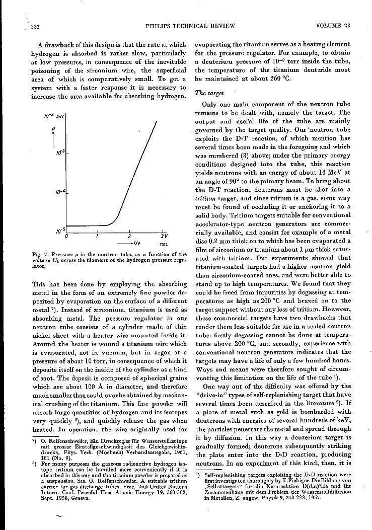
A drawback ofthis design is that the rate at whichhydrogen is absorbed is rather slow, particularlyat low pressures, in consequence of the inevitablepoisoning of the zirconium wire, the superficialarea of which is comparatively small. To get asystem with a faster response it is necessary toincrease the area available for absorbing hydrogen.
/0-2 torr
î
10-4
IO-S'=- +- _...!... L;
o 2 3V_Ut 7372
Fig. 7. Pressure p in the neutron tube, as a function of thevoltage Ur across the filament of the hydrogen pressure regu-lator.
This has been done by employing the absorbingmetal in the form of an extremely fine powder de-posited by evaporation on the surface of a differentmetal."}, Instead of zirconium, titanium is used asabsorbing metal. The pressure regulator in ourneutron tube consists of a cylinder made of thinnickel sheet with a heater wire mounted inside it.Around the heater is wound a titanium wire whichis evaporated, not in vacuum, but in argon at apressure of about 10 torr, in consequence ofwhich itdeposits itself on the inside of the cylinder as a kindof soot. The deposit is composed of spherical grainswhich are about 100 Á in diameter, and thereforemuch smaller than could ever be obtained by mechan-ical crushing of the titanium. This fine powder willabsorb large quantities of hydrogen and its isotopesvery quickly 8), and quickly release the gas whenheated. In operation, the wire originally used for
7) O. Reifenschweiler, Ein Druckregler für Wasserstoffisotopemit grosser Einstellgeschwindigkeit des Gleichgewichts-drucks, Phys. Verh. (Mosbach) Verbandsausgabe, 1961,181 (No. 9).
8) For many purposes the gaseous radioactive hydrogen iso-tope tritium can be handled more conveniently if it isabsorbed in this way and the titanium powder is prepared asa suspension. See. O. Reifenschweiler, A suitable tritiumcarrier for gas discharge tubes, Proc. 2nd United NationsIntern. Conf. Peaceful Uses Atomic Energy 19, 360-362,Sept. 1958, Geneva.
evaporating the titanium serves as a heating elementfor the pressure regulator. For example, to obtaina deuterium pressure of 10-3 torr inside the tube,the temperature of the titanium deuteride mustbe maintained at about 260°C.
The target
Only one main component of the neutron tuberemains to be dealt with, namely the target. Theoutput and useful life of the tube are mainlygoverned by the target quality. Our 'neutron tubeexploits the D-T reaction, of which mention hasseveral times been made in the foregoing and whichwas numbered (3) above; under the primary energyconditions designed into the tube, this reactionyields neutrons with an energy of about 14 MeV atan angle of 90° to the primary beam. To bring aboutthe D-T reaction, deuterons must be shot into atritium target, and since tritium is a gas, some waymust he found of occluding it or anchoring it to asolid body. Tritium targets suitable for conventionalaccelerator-type neutron generators are commer-cially available, and consist for example of a metaldisc 0.2 mm thick on to which has been evaporated afilm of zirconium or titanium about 1 fLmthick satur-ated with tritium. Our experiments showed thattitanium-coated targets had a higher neutron yieldthan zirconium-coated ones, and were better able tostand up to high temperatures. We found that theycould be freed from impurities by degassing at tem-peratures as high as 200°C and brazed on to thetarget support without any loss of tritium. However,these commercial targets have two drawbacks thatrender them less suitable for use in a sealed neutrontube: firstly degassing cannot he done at tempera-tures above 200°C, and secondly, experience withconventional neutron generators indicates that thetargets may have a life of only a few hundred hours.Ways and means were therefore sought of circum-venting this limitation on the life of the tube 1).
One way out of the difficulty was offered by the"drive-in" types of self-replenishing target that haveseveral times been described in the literature 9). Ifa plate of metal such as gold is bombarded withdeuterons with energies of several hundreds of keV,the particles penetrate the metal and spread throughit by diffusion. In this way a deuterium target isgradually formed; deuterons subsequently strikingthe plate enter into the D-D reaction, producingneutrons. In an experiment of this kind, then, it is
0) Self-replenishing targets exploiting the D-D reaction werefirst investigated thoroughly byK.Fiebiger, DieBildung von"Selbsttargets" für die Kernreaktion D(d,n)3He und ihrZusammenhang mit dem Problem der Wasserstoffdiffusionin Metallen, Z. angew. Physik 9,213-223, 1957.
1961/62,No. 11 NEUTRON TUBE 333
very soon found that neutrons are being emitted,and the rate of emission increases as time goes on.Generally, after a certain lapse of time, the yieldattains a saturation value. The reason is that, by thistime, a certain proportion of the deuterons shot intothe metal are diffusing back to the surface and out ofthe plate. A steady state of saturation is attainedwhen the deuterons diffuse out of the target at thesame rate as they are shot into it.The proportion of deuterons "used up" by nuclear
reactions is extremely small, so small that it has noeffect on the constitution of a self-replenishing tar-get. Fiebiger's experiments 9) indicated that thehighest saturation concentration of deuterons andthe greatest neutron yield was obtainable with agold self-replenishing target.
So far we have dealt only with the self-replenish-ing target for the D-D reaction. One exploiting theD-T reaction can be produced by filling the neutrontube with a mixture of tritium and deuterium andusing it to bombard the target. As a result, tritiumas well as deuterium penetrates the target material,and enters into reaction with the incident deuterons.True, it also happens under these circumstancesthat deuterium and tritium ions strike deuteriumatoms and that tritium ions strike tritium atoms, inconsequence of which the neutron yield is only athird of that available when a pure tritium target isbombarded with deuterons. Measurements andapproximate calculations have shown that, of theabove competing reactions, only the D-T and T-Dreactions - which naturally yield neutrons of thesame energy - make any appreciable contributionto the output of the tube.
The reasoning underlying the above statements is as follows.Let us assume that, in a tube filledwith deuterium and tritiumin equal proportions, the ion beam and the gas absorbed intothe target are also 1:1 mixtures of the two isotopes. Thechances of a D-T, a T-D, a D-D and a T-T impact are in eachcase 25% of the probability that a D-T impact will take placein a tube with a pure tritium target and a beam composed ex-clusively of deuterons, other conditions (beam current, gascontent of target etc.) being the same. The output from atube of the latter kind may amount to 5X lOBneutrons/sec;if this is regarded as a 100% yield, then the yield of 14-MeVneutrons from the D-T reaction in the tube filledwith a gasmixture will only be 25%.In regard to the contribution of the T-D reaction to the
neutron yield of the tube, it must be remembered that thetritium ion has a mass 50% greater than that of a deuteron;consequently, the kinetic energy of the tritium ions in thebeam, measured in relation to the centre of gravity of the sys-tem formed by the two reacting particles, is only two-thirdsthat of deuterons accelerated through the same potentialdifference.
The energy available for a nuclear reaction is equal to thekinetic energy of the reacting particles due to their motionrelative to their common centre of gravity; their movementrelative to an outside frame of reference is irrelevant. Conse-quently 6O-keVtritium ions are only equivalent to 40-keVdeuterons. On account of the smaller effective cross-sectionofthe D-T reaction at 40keY, its neutron yield at this primaryenergy is only a quarter of what it would be at a primaryenergy of 60 keY. This latter, as we have already established,would be 25% of the yield from a tritium-target deuteron-beam tube. The actual yield of 14MeVneutrons from the T-Dreaetion is therefore about 6%.The contribution of the D-D reaction canbe worked out from
the measured yield from tubes filled with pure deuterium.These have been found, under the same operating conditions,to produce 5X10⁵ neutrons/sec. In the mixture-filled tube onlya quarter of the reactions are D-D reactions. Accordingly, thesewill contribute 1.25xl05 neutrons (of 2.5 MeV) per second,which represents less than 0.1% of the overall yield from a"pure" D-T tube.Finally, in regard to impacts of tritium ionson tritium atoms,
the chance of a nuclear reaction resulting from these is soslight at the accelerating voltages employed that it can beneglected altogether.On adding the above contributions together we arrive at a
figure of about 31%. Accordingly, a neutron tube filled with adeuterium-tritium mixture has a yield about one-third of thatfrom a tube with a pure tritium target and a beam composedexclusively of deuterons. Of this overall yield, the D-T reactionis responsible for four-fifths and the T-D reaction for one-fifth,both these reactions yielding 14-MeVneutrons. The D-D reac-tion, yielding 2.5-MeVneutrons, contributes less than 0.1% tothe tube output.The above considerations still fail to take full account of
aetual conditions in the tube, since the particles accelerated aremainly molecular ions, not monatomic ones.During absorptioninto and desorption from the hydrogen pressure regulator, theformation of D-T moleculesmay occur, so that we really havethree kinds of molecule to deal with; in the ideal case thesewould be present in the proportions 1:2:1.However, the resultof a more elaborate study taking account of all such factorswould not differ appreciably from the figurejust arrived at.
The use of drive-in targets removes a limitationon the tube life, which ceases to be dependent onthat of the target. A further advantage is that thetemperature at which the tube can be degassed andevacuated ceases to be governed by the thermalproperties of the target, since this is not chargedwith gas until after the tube has been sealed. Still,as has already been shown, the usual type of drive-intarget has a smaller neutron yield than the targetscommercially available, and fór that reason we castabout for a better type. As will now be explained, wehave succeeded in designing drive-in targets thathave an appreciably higher neutron yield.
Gold, which Fiebiger's experiments indicated wasthe best material for drive-in targets, does notnaturally occlude hydrogen isotopes. In fact, inthe target experiments, it is forced to absorb theisotopes, these being shot into it at high velocity;

334 PHILIPS TECHNICAL REVIEW VOLUME 23
thereafter, they distribute themselves throughthe metal by diffusion. The diffusion coefficientof hydrogen isotopes in gold is small but, ofcourse, increases with temperature. Consequentlyit is only in a superficiallayer of the target heated byion bombardment (the thickness of,' which corres-ponds to the maximum range of the ions penetra-ting the surface) that distribution of the hydrogenisotopes is at all efficient, by reason of the ratherhigher diffusion coefficient of this heated layer.Hence the highest concentration obtainable withinthe layer penetrated by incident ions - the onlypart of the target where nuclear reactions are likelyto take place - is governed by the rate at which theions are diffusing out of the layer via the targetsurface; diffusion into the depth of the target, awayfrom the surface, can be neglected. This theory ofFiebiger's was confirmed by his experiments on goldtargets 9). The above is outlined in visual terms injig. Ba.
Unlike gold, the metals zirconium and titaniumare able to go on absorbing hydrogen isotopes exo-thermically right up to the point of hydride for-
35 5 5 5
2 2 2 2 2
o
Q
Fig. 8. The diagrams represent, schematically, various typesof drive-in targets exploiting the D-D reaction.a) Fiebiger's gold target 9). Gold is a non-occluder of hydrogenisotopes: it does however absorb deuterium when bombardedwith deuterons (1) of sufficient energy to effect pen-etration to some depth. In a thin layer of the target (greyarea in the diagram) the deuteron concentration graduallyattains a steady state as the nett result of a number of pro-cesses - penetration of the deuterons, their diffusion throughthe metal (only at high temperature), heating of the metalby the deuteron bombardment, and escape of the par-ticles by diffusion out of the target (2). Deuterons present inthe target may enter into neutron-yielding nuelear reactions(4) with newly arriving deuterons (3) or , alternatively, theselatter may merely contribute to maintaining the concentrationin the target (5). Curve I in diagram d shows the presumed con-centration distribution of deuterium in a saturated drive-intarget of gold 9).b) Solid titanium target. The numerals 1 to 5 have the samesignificance as in u.. Unlike gold, titanium is an exothermicabsorber ofhydrogen isotopes, absorbing deuterium very readilyup to the point of TiD2 formation; a high saturation concen-tration ought therefore to be attainable in a titanium target.However, the incident deuterons cannot build up this high con-centration because of the high diffusion coefficient of hydrogen
mation, a property exploited in the pressure regu-lator. This means that throughout the chargingprocess, i.e. until the target has become saturated,there is a potential barrier at its surface, hinderingthe escape of hydrogen isotopes from the metal. Itis therefore easier to achieve and maintain a highconcentration of hydrogen isotopes in titanium orzirconium than in gold, provided only that somemeans can be found of preventing too many of thehydrogen atoms from escaping at the other side,beyond the limit of the reaction zone, as they areliable to do in consequence of the high diffusioncoefficients of zirconium and titanium. This is madeclear in fig. 8b. It is obvious that in Fiebiger'sexperiments on drive-in targets, zirconium andtitanium only gave poorer neutron yields thangold because the ions were escaping at the backdoor, so to speak.Diffusion out of the reaction zone can be prevented
by using the target metal in the form of a thin layerapplied to a base with a low diffusion coefficient forhydrogen. The thickness of the layer must more orless correspond to the range of penetration of the
1 1
3 35 5
2 2
III
isotopes in titanium even at room temperature. In consequenceof this most of the deuterons diffuse further into the metal (6),out of the reaction zone. (The particles have to overcome apotential barrier before emerging from the target surface (2)and this effect is therefore unimportant.) Curve 11 in diagram dshows the presumed concentration distribution of deuterium ina titanium target; the neutron yield from such a target isaccordingly smaller than in case a.c) This diagram represents the backed titanium-film drive-intarget employed in the neutron tube 1). The thickness of thefilm is rather greater than the maximum range of the incidentions (1) in titanium and the backing metal is one that has a lowdiffusion coefficient for hydrogen. It is impossible for the par-ticles to diffuse further into the depth of this target (6) and con-sequently the concentration of deuterons obtainable in thetitanium film is very high. Curve III of diagram d shows thepresumed distribution of deuterium densities. The neutronyield is three times as great as in case a.
Diagrams a, band c are of course applicable to the D-T reac-tion as well as to the D-D reaction. In fact only a proportionof the small circles are to be regarded as deuterons; the othersrepresent tritons. In addition to neutrons, a-particles are pro-duced as a result of the D-T reaction (as shown); in the D-Dreaction, however, 3He nuclei are produced instead of thea-particles.
1961/62, No. 11 NEUTRON TUBE 335
ions. On bombardment, the layer becomes chargedup to saturation in a comparatively short time(about 15 hours at a beam current of 100 [LA);the saturation concentration of hydrogen isotope ishigh (see fig. 8e). The present neutron tube is equip-ped with a target of this kind, consisting of anapproximately 1 (.Lm film of titanium evaporated on toa silver base. For an acceleration voltage of 125 kVand an ion current of 100 [LA,a yield of over 108
neutrons/sec is obtained. Measured yields from thebest of these targets have attained the figure of2.4 X 108 neutrons/sec.Apart from providing a roughly three times higher
neutron yield, the titanium-film target has theadvantage over the gold drive-in target of beingbetter able to stand up to elevated temperatures,remaining stable up to 200°C. Fiebiger found thatthe neutron yield from gold targets fell off steeplyabove 120°C.
The neutron tube in operatien
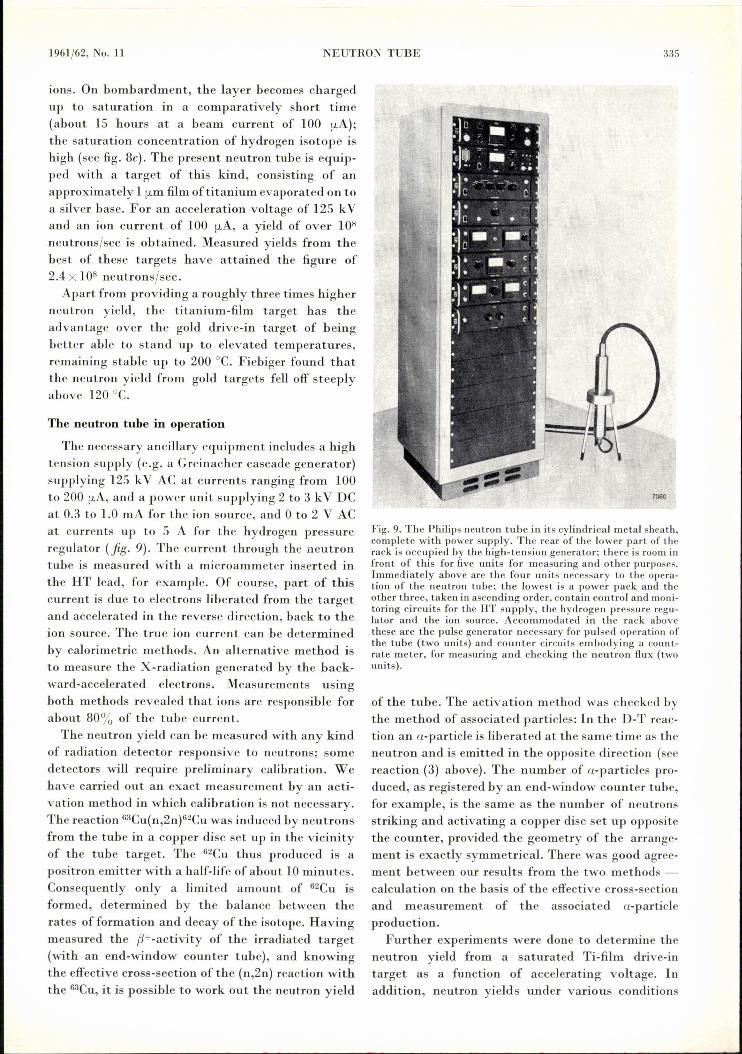
The necessary ancillary equipment includes a hightension supply (e.g. a Greinacher cascade generator)supplying 125 kV AC at currents ranging from 100to 200 [LA,and a power unit supplying 2 to 3 kV DCat 0.3 to 1.0 mA for the ion source, and 0 to 2 V ACat currents up to 5 A for the hydrogen pressureregulator (jig. 9). The current through the neutrontube is measured with a microammeter inserted inthe HT lead, for example. Of course, part of thiscurrent is due to electrons liberated from the targetand accelerated in the reverse direction, back to theion source. The true ion current can be determinedby calorimetrie methods. An alternative method isto measure the X-radiation generated by the back-ward-accelerated electrons. Measurements usingboth methods revealed that ions are responsible forabout 80% of the tube current.The neutron yield can be measured with any kind
of radiation detector responsive to neutrons; somedetectors will require preliminary calibration. Wehave carried out an exact measurement by an acti-vation method in which calibration is not necessary.The reaction 63Cu(n,2n)62Cuwas induced by neutronsfrom the tube in a copper disc set up in the vicinityof the tube target. The 62Cu thus produced is apositron emitter with a half-life of about 10minutes.Consequently only a limited amount of 62CU isformed, determined by the balance between therates of formation and decay of the isotope. Havingmeasured the f1+-activity of the irradiated target(with an end-window counter tube), and knowingthe effective cross-section of the (n,2n) reaction withthe 63CU,it is possible to work out the neutron yield
Fig. 9. The Philips neutron tube in its cylindrical metal sheath,complete with power supply. The rear of the lower part of therack is occupied by the high-tension generator; there is room infront of this for five units for measuring and other purposes.Immediately above are the four units necessary to the opera-tion of the neutron tube; the lowest is a power pack and theother three, taken in ascending order, contain control and moni-toring circuits for the HT supply, the hydrogen pressure regu-lator and the ion source. Accommodated in the rack abovethese are the pulse generator necessary for pulsed operation ofthe tube (two units) and counter circuits embodying a count-rate meter, for measuring and checking the neutron flux (twounits).
of the tube. The activation method was checked bythe method of associated particles: In the D-T reac-tion an a-particle is liberated at the same time as theneutron and is emitted in the opposite direction (seereaction (3) above). The number of a-particles pro-duced, as registered by an end-window counter tube,for example, is the same as the number of neutronsstriking and activating a copper disc set up oppositethe counter, provided the geometry of the arrange-ment is exactly symmetrical. There was good agree-ment between our results from the two methods -calculation on the basis of the effective cross-sectionand measurement of the associated a-particleproduction.
Further experiments were done to determine theneutron yield from a saturated Ti-film drive-intarget as a function of accelerating voltage. Inaddition, neutron yields under various conditions

336 PHILIPS TECHNICAL REVIEW VOLUME 23
were calculated from the effective cross-sectionof the D-T reaction and the atomic stoppingpower of titanium tritide, for different ion beamcompositions and for two different targets, onewith a tritium-titanium ratio of 1:1 and the otherwith a deuterium-tritium-titanium ratio of 1:1:2.The results are displayed in fig. 10. It will benoted that the measured curve lies very close tothe relevant calculated one. At an accelerating volt-age of 125 kV and an ion current of 100 !LA-under which operating conditions the tube is verystable - a yield of more than 108 neutrons/secis obtained. Fig. 10 also shows that the employmentof a pure tritium target and a pure deuterium atmos-phere would increase the neutron yield by a factor of3; however, as has already been explained, the life ofthe tube would then be limited to a few hundredhours.
The drive-in target actually embodied in the tubehas an almost unlimited life. Several tubes' takenfrom the production line have been life-tested underthe above conditions (accelerating voltage of 125
Nn
i 1081----1---1--1-1.1+---;---...,
-u 7374
Fig. 10. The yield Nn in neutrons per second at a tube currentof 100 (.LA, as a function of the accelerating voltage U. Curves1,2 and 3 are theoretical, and curve 4is experimental. Curve 1has been plotted from calculated yields based on the effectivecross-section of the D-T reaction and on the atomic stoppingpower of the titanium tritride in a target in which titanium andtritium are present in the ratio of I:!, Furthermore, the ionbeamhas been assumed to bc composed exclusively of monatomicD+ ions (deuterons). Curve 2 relates to the case where the ionbeam is mainly composed of molecularD2+ions; neutron yieldsare only one-third of those obtained in the case to which curve 1relates. Curve 3 shows calculated neutron yields in the casewhere the filler gas, and hence the ion beam, is a 1:1 mixture ofdeuterium and tritium (molecular ions) and the target is atitanium-film drive-in type, all other conditions remaining thesame. These are the conditions appropriate to the final versionof the neutron tube, and there is good agreement between thistheoretical curve and curve 4, which is a plot of values obtainedfrom actual m\la~1J~ements.
kV at ion currents of 100 or 200 !LA,corresponding toneutron yields exceeding ~08 and 2 X10⁸ neutrons/sec respectively) for periods exceeding 1000 hours;one tube has been run for 4·000hours. No fall-off inreliability of operation or in neutron yield could bedetected either during or after these tests.
The neutron yield can be adjusted to any desiredvalue between zero and maximum by varying theaccelerating voltage; an alternative method of con-trolling the tube output is by adjusting the gaspressure in the tube or the voltage across the ionsource. It is also possible to stabilize the neutronyield; generally it suffices to keep the ion sourcecurrent constant, and this can be done automaticallyby a feedback arrangement whereby this currentcontrols the voltage across the hydrogen pressureregulator. About 10-3 torr has been found to be themost favourable gas pressure.
A pulsed neutron output is desirable in manyapplications of the tube; this can easily be effectedby pulsing the ion source voltage. The minimumusable pulse duration is 5 !LS.During a pulse, theneutron yield is about 10 times greater than it isunder continuous operation; hence, if the pulseoccupies 10% of the cycle (i.e. intervals 9 times thepulse length) the mean neutron output will beroughly the same as under continuous operation.
Applications of sealed-off neutron tubes
Finally, let us take a look at a few typical applica-tions of neutron tubes. It must be made clear fromthe outset that these sources are not designed toproduce the less common elementary particles thatare the speciality of extremely large accelerators.The usefulness of the neutron tube described herelies rather in the fact that it is a particularly simple,convenient and comparatively cheap source of fast,monoenergetic neutrons, its main advantage overconventional accelerators being that it is readilytransportable.
Fundamental research in nuclear physics, andparticularly in neutron physics, immediately sug-gests itself as the most obvious field of applicationfor neutron tubes in those cases where a yield 108neutrons/sec is sufficient. The tubes are accordinglybeing used for investigating the elastic and inelasticscattering of fast neutrons, for studying slow neu-tron capture, for producing radioactive isotopes andinvestigating their properties, and for calibratingneutron spectrometers 10), Wilson chambers, bubblechambers and nuclear emulsions.10) L. J. de Vries and F. Udo, A fast pulse-shape discriminator
with applications as a spectrometer and sensitive monitorfor 1-30 MeV neutrons, Nucl. Instr. and Meth.13, 153-160,1961 (No. 2).
.3371961/62, No. 11 NEUTRON TUBE ' ..A further broad field of application for neutron
tubes arises out of the employment of the neutron infields outside nuclear physics for the solution of bothpurely scientific and more immediately practicalproblems. For example, the tubes are convenientfor producing small quantities of short-lived artifi-cial radioactive isotopes on the spot. This facility isof value in chemical and biological research, and it isrelevant to many of the problems with which engi-neers are confronted. It is particularly in connectionwith the production of short-lived isotopes that theadvantages of the neutron tube become evident:normally a nuclear reactor is not available at theplace where the isotopes are to be used, and the timerequired for transportation prohibits irradiation ofthe material in a reactor some distance away.A further, related field of application is that of
non-destructive analysis. Here a distinction must bemade between two methods - activation analysis,and analysis bymeans of directlyinduced y-emission.In activation analysis the sample is irradiated withfast or slow neutrons (cf. the method for measuringneutron yield described above). By investigatingthe resulting radioactivity of the sample - thehalf-life and/or the nature of the emitted radiation- the presence of various chemical elementscan be determined quantitatively often with greataccuracy. Almost all the elements can be identified inthis way, though in some cases it may he necessaryto undertake separation first or treat the sampleafterwards, using ordinary chemical methods.In the second method of non-destructive analysis,
a y-spectrometer is employed to investigate they-radiation generated during neutron bombardmentof the sample by inelastic scattering of fast neutronsor by slow neutron capture (n,y reaction). Analysisof the resulting y-spectrum is thus analogous toX-ray spectrometry.
Both methods of analysis are highly suitable forgeological in vestigations, the mobility of the neutrontube making it possible to assay mineral samples inthe field. A typical application of great practicalimportance is the detection of petroleum in the vicin-ity of drillings ("oil-well logging"). Together witha suitable detector, the neutron source is loweredinto the drill hole. In principle the activationmethod of analysis just described allows all geolog-ically important elements to he identified. Methodsbased on the recording of y-spectra seem to offereven better prospects, in view of the fact thaty-radiation can he detected more easily and moreefficiently. A particularly useful aspect of these
methods is the possibility of exploiting the delay be-tween the y-radiation generated by fast neutrons(i.e. due to inelastic scattering of the 14 MeVneutrons coming direct from the tube) and they-radiation generated by thermal neutrons (thoseslowed down by elastic scattering). This enables theelements carbon and oxygen to he differentiatedmore clearly from hydrogen, silicon and chlorineand, accordingly, salt or fresh water to be readilydistinguished from mineral oil. Methods exploitingthese time differences naturally call for a pulse-operated source of fast neutrons 11).The study of reactor materials represents another
important field of application for neutron tubeswith facilities for pulsed operation. Certain proper-ties of reactor materials, important from the view-point of neutron physics, can be measured in sub-critical rigs by injecting the materials with a brief,intense burst of neutrons. The tubes are also con-venient for testing neutron-shielding materials.
Of no less importance is the employment of theneutron tube in education and technical training.The tube is simple to operate, it can be adjusted tosupply any desired flux from zero to the maximum,and it should therefore represent an ideal neutronsource for demonstrations in the lecture theatre andfor practical work in the laboratory, opening up theinteresting field of artificial radioactivity as well asthat of neutron physics proper.
11) R. L. CaldweIland W. R. MillsJr., Nucl. Instr. andMeth. 5,312, 1959; J. Tittman and W. B. Nelligan, Amer. Inst.Mining Engrs Casper (Wyoming) meeting, April 1959,Paper 1227G;B. G. Erozolimskü, A. S. Shkol'nikov and A.1. Isakov, Atomic Energy (Moscow)9, 144, 1960.
Summary. After a brief review of current types of neutronsources, the authors describe a neutron source tube which isabout the size of an X-ray tube, and is operated in a similarway. Supplied with a direct voltage of 125kV, this tube is capa-ble of generating neutrons with an energy of 14 MeV at ratesexceeding 108 neutrons/sec. The neutrons arise out of a nuclearreaction between tritium and deuterium: T(d,n)4I·Ie. Thedeuterons are produced in a Penning ion source and acceleratedup to 125 keY in a single-stage accelerating system. Theystrike a target consisting of al {Lmfilm of titanium which hasbeen evaporated on to a silver base, and which contains tri-tium. The tube is filled with a deuterium-tritium mixture at apressure of about 10-3 torr; consequently the target is bom-barded with tritium ions as well as deuterium ions, and in thisway its charge of tritium is kept at saturation more or lessindefinitely. The life of the tube is not therefore limited by thatof the target. The pressure inside the tube is adjusted by meansof a built-in replenisher containing a large reserve of D-T mix-ture, so enabling gas clean-up to he compensated and removinga further restrietion on the life of the tube. In life tests, anumber of tubes have worked for periods exceeding 1000hours(one for 4000 hours) without any fall-offin operating reliabilityor neutron yield. The yield from the tube can attain 109neutrons/see when it is pulse-operated (the shortest pulseduration is 5{Ls).In conclusion, some typical applications forthis type of neutron tube are touched upon.
Related Documents


