Phenomenology during the loss of residual heat removal system at midloop conditions with pressurizer PORVs open: Associated boron dilution Isaac Gonza ´lez * , Ce ´sar Queral, Antonio Expo ´ sito 1 Energy Systems Department, Universidad Polite ´cnica de Madrid, Rı ´os Rosas, 21, 28003 Madrid, Spain Received 27 September 2006; accepted 13 November 2006 Available online 20 February 2007 Abstract The loss of residual heat removal system (RHRS) at midloop operation is an important risk contributor at low power and shutdown conditions. In this kind of transient the reflux-condensation can play an important role during the sequence to avoid the core damage. Several simulations concerning the loss of the RHRS in a PWR-W with the pressurizer PORVs open have been carried out with TRACE code considering the availability of steam generators. The present study aims to analyze, firstly, the thermal-hydraulic behavior after the loss of RHRS at midloop conditions throughout different configurations with reflux-condensation as the sole cooling mechanism avail- able, and secondly, the issue related to the boron dilution that takes place during this kind of transient. The simulation results show that in the open RCS configuration, an equilibrium pressure is obtained in all cases and the reflux-condensation removes an important part of the decay heat. Moreover, in some configurations, this mechanism may cause the formation of an unborated water slug in the crossover leg that can lead to a boron dilution sequence. Ó 2007 Elsevier Ltd. All rights reserved. 1. Introduction During reactor shutdown in a PWR-W, core decay heat is removed by RHRS, which takes coolant at high temper- ature from the hot legs and returns the cooled liquid through the cold legs to the vessel. In this plant operating state, the inspection and maintenance of certain compo- nents such as steam generator U-tubes and the reactor coolant pumps, could be required with the reactor level reduced to the height of the primary loop. The loss of RHRS in this particular condition, so-called midloop oper- ation, is an important risk contributor at low power and shutdown (LPS) conditions (NRC, 1993; IAEA-TEC- DOC-1042, 1998; NRC, 1994). After a loss of RHRS at midloop operation, other cool- ing mechanisms are required in order to avoid the fuel damage or mitigate the severity of the accident. These mechanisms could be feed and bleed, gravity feed from refueling water storage tank (RWST) or reflux-condensa- tion (Naff et al., 1992). In the latter one, the steam flows through the steam generators tubes where eventually con- denses and drains back to the hot legs. The efficiency of this mechanism depends on the configuration of the plant, open or closed primary system, the number of steam generators available and the residual heat level. It must be also taken into account that the reflux-condensation can lead to boron dilution in the loop seal due to the formation of clean water in U-tubes, like in SBLOCA sequences (Hyvarinen, 1993). The objectives of this paper are to analyze the capability of the reflux-condensation as a mechanism of cooling in an open RCS (two PORVs open), and to check if there is a safety issue related to the boron dilution that takes place during the loss of RHRS at midloop conditions. To 0306-4549/$ - see front matter Ó 2007 Elsevier Ltd. All rights reserved. doi:10.1016/j.anucene.2006.11.014 * Corresponding author. E-mail addresses: [email protected] (I. Gonza ´lez), [email protected] (C. Queral), [email protected] (A. Expo ´ sito). 1 Tel.: +34 913367061. www.elsevier.com/locate/anucene Annals of Nuclear Energy 34 (2007) 166–176 annals of NUCLEAR ENERGY

Welcome message from author
This document is posted to help you gain knowledge. Please leave a comment to let me know what you think about it! Share it to your friends and learn new things together.
Transcript
www.elsevier.com/locate/anucene
Annals of Nuclear Energy 34 (2007) 166–176
annals of
NUCLEAR ENERGY
Phenomenology during the loss of residual heat removalsystem at midloop conditions with pressurizer PORVs
open: Associated boron dilution
Isaac Gonzalez *, Cesar Queral, Antonio Exposito 1
Energy Systems Department, Universidad Politecnica de Madrid, Rıos Rosas, 21, 28003 Madrid, Spain
Received 27 September 2006; accepted 13 November 2006Available online 20 February 2007
Abstract
The loss of residual heat removal system (RHRS) at midloop operation is an important risk contributor at low power and shutdownconditions. In this kind of transient the reflux-condensation can play an important role during the sequence to avoid the core damage.Several simulations concerning the loss of the RHRS in a PWR-W with the pressurizer PORVs open have been carried out with TRACEcode considering the availability of steam generators. The present study aims to analyze, firstly, the thermal-hydraulic behavior after theloss of RHRS at midloop conditions throughout different configurations with reflux-condensation as the sole cooling mechanism avail-able, and secondly, the issue related to the boron dilution that takes place during this kind of transient. The simulation results show thatin the open RCS configuration, an equilibrium pressure is obtained in all cases and the reflux-condensation removes an important part ofthe decay heat. Moreover, in some configurations, this mechanism may cause the formation of an unborated water slug in the crossoverleg that can lead to a boron dilution sequence.� 2007 Elsevier Ltd. All rights reserved.
1. Introduction
During reactor shutdown in a PWR-W, core decay heatis removed by RHRS, which takes coolant at high temper-ature from the hot legs and returns the cooled liquidthrough the cold legs to the vessel. In this plant operatingstate, the inspection and maintenance of certain compo-nents such as steam generator U-tubes and the reactorcoolant pumps, could be required with the reactor levelreduced to the height of the primary loop. The loss ofRHRS in this particular condition, so-called midloop oper-ation, is an important risk contributor at low power andshutdown (LPS) conditions (NRC, 1993; IAEA-TEC-DOC-1042, 1998; NRC, 1994).
0306-4549/$ - see front matter � 2007 Elsevier Ltd. All rights reserved.
doi:10.1016/j.anucene.2006.11.014
* Corresponding author.E-mail addresses: [email protected] (I. Gonzalez), [email protected]
(C. Queral), [email protected] (A. Exposito).1 Tel.: +34 913367061.
After a loss of RHRS at midloop operation, other cool-ing mechanisms are required in order to avoid the fueldamage or mitigate the severity of the accident. Thesemechanisms could be feed and bleed, gravity feed fromrefueling water storage tank (RWST) or reflux-condensa-tion (Naff et al., 1992). In the latter one, the steam flowsthrough the steam generators tubes where eventually con-denses and drains back to the hot legs. The efficiency of thismechanism depends on the configuration of the plant, openor closed primary system, the number of steam generatorsavailable and the residual heat level. It must be also takeninto account that the reflux-condensation can lead to borondilution in the loop seal due to the formation of clean waterin U-tubes, like in SBLOCA sequences (Hyvarinen, 1993).
The objectives of this paper are to analyze the capabilityof the reflux-condensation as a mechanism of cooling in anopen RCS (two PORVs open), and to check if there is asafety issue related to the boron dilution that takes placeduring the loss of RHRS at midloop conditions. To
Nomenclature
CCFL countercurrent flow limitCFD computational fluid dynamicsCSN Consejo de Seguridad NuclearCVCS chemical and volume control systemLPS low power and shutdownNPP nuclear power plantPORV power operated relief valve
PWR-W pressurized water reactor, Westinghouse designRCS reactor coolant systemRHRS residual heat removal systemRWST refueling water storage tankSG steam generatorTCU time to core uncoveryT-H thermal-hydraulics
I. Gonzalez et al. / Annals of Nuclear Energy 34 (2007) 166–176 167
analyze these aspects, several simulations have been per-formed with the TRACE (TRAC/RELAP Advanced Com-putational Engine) model of Almaraz NPP (three loop,Westinghouse design).
2. TRACE model of Almaraz NPP
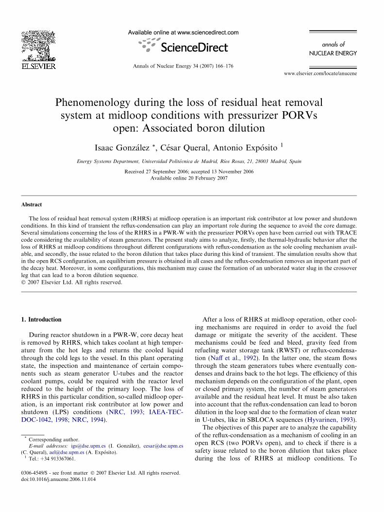
The TRACE model of Almaraz NPP (Fig. 1) is made upof 252 thermohydraulic components (including a 3D VES-SEL), 685 Signal Variables, 1532 Control Blocks and 47Trips. The shutdown model has been obtained from the fullpower one (Gonzalez et al., 2005; Queral et al., 2006a;Gonzalez, 2005) including the CCFL model in pressurizersurge line and U-tubes (CSNI-97, 1997) and the offtakemodel in the connection between surge line and hot leg.A detailed nodalization of the vessel and the crossover legshas also been necessary, the first one to reach midloop con-ditions and the second to minimize numerical diffusion dur-ing the generation of the unborated slug.
The simulation capability of the TRACE code (NRC,2003) with 3D VESSEL models in low power and shut-down sequences has been confirmed with the simulationsof several PKL experiments (Jasiulevicius, 2005;Jasiulevicius et al., 2006). The reason of including a 3DVESSEL component is to reproduce the natural circulationthrough the whole vessel, which could be quite importantin this kind of transient (Seul et al., 2000; Bang and Kim,1996).
3. Simulation of loss of RHRS sequences at midloop level
This paper includes the results of the simulations ofloss of RHRS at midloop operation with vented RCS(two PORVs open) and those corresponding to closedscenarios obtained in a previous paper (Queral et al.,2006b). Different steam generators availabilities has beenconsidered in order to analyze the capability of the reflux-condensation as a cooling mechanism in different config-urations. One of the reasons to perform these simulationsis that several analysis for PWR-W design has been foundfor open scenarios with large vent such as the pressurizerand steam generators manways open (Hassan and Raja,1993; Seul et al., 2000; Ferng and Ma, 1996); but onlyone considers a small opening, a vessel vent valve (Kimet al., 2000).
The initial conditions and hypothesis of the modelare:
� Midloop level (mass inventory of almost 73,000 kg).� Initial pressure 1 bar, initial temperature 333.15 K.� 11 MW of thermal power.� The pressurizer is connected in loop 2.� Availability of steam generators:
– Three steam generators full of water: 3SG.– Two steam generators full of water and one full of air
(loop 3): 2SG.– One steam generator full of water (loop 1) and the
rest containing air: 1SG.– All steam generators full of air: 0SG.� Secondary pressure: 1 bar.� No auxiliary feedwater and feed of coolant
available.
The main variables of these sequences are: time to boil,time to core uncovery (TCU), maximum pressure and max-imum clad temperature. The results obtained in the caseswith two PORVs open (nSGO) and closed scenarios(nSGC) are shown in Table 1.
In all the sequences the core reaches saturation 10 minafter the loss of RHRS. Later, part of the steam flowsthrough the hot legs to the vent, and the remainder to U-tubes, where it is condensed. The condensed liquid returnsto the external parts of the core through the hot legs. Thisleads to a natural circulation flow throughout the internaland external parts of the core region. The overall phenom-enology has also been observed in the experiments carriedout in IIST (Lee et al., 1995; Seul et al., 1999).
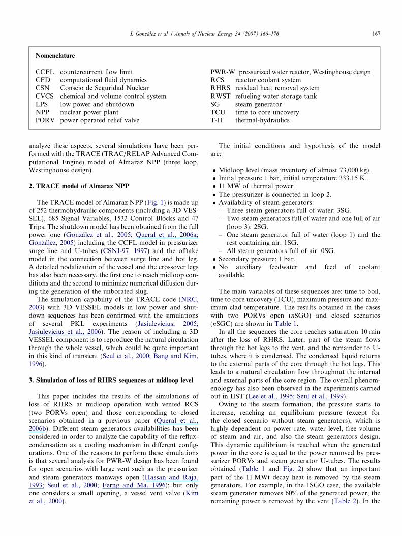
Owing to the steam formation, the pressure starts toincrease, reaching an equilibrium pressure (except forthe closed scenario without steam generators), which ishighly dependent on power rate, water level, free volumeof steam and air, and also the steam generators design.This dynamic equilibrium is reached when the generatedpower in the core is equal to the power removed by pres-surizer PORVs and steam generator U-tubes. The resultsobtained (Table 1 and Fig. 2) show that an importantpart of the 11 MWt decay heat is removed by the steamgenerators. For example, in the 1SGO case, the availablesteam generator removes 60% of the generated power, theremaining power is removed by the vent (Table 2). In the
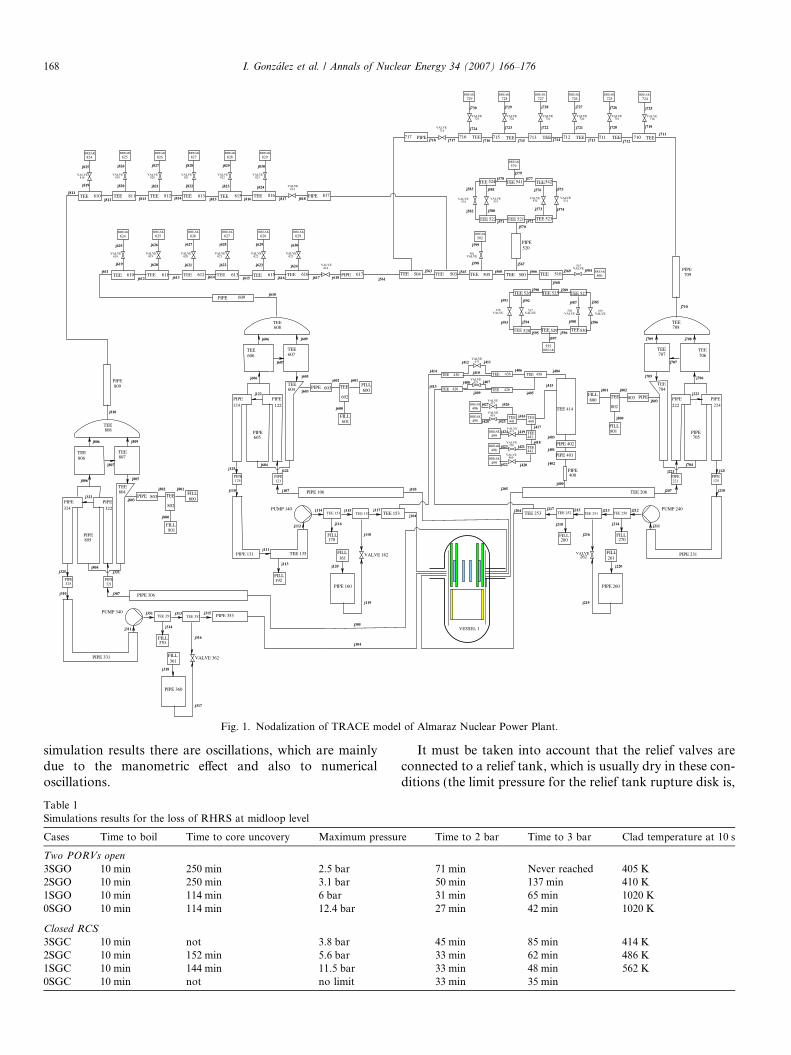
Fig. 1. Nodalization of TRACE model of Almaraz Nuclear Power Plant.
168 I. Gonzalez et al. / Annals of Nuclear Energy 34 (2007) 166–176
simulation results there are oscillations, which are mainlydue to the manometric effect and also to numericaloscillations.
Table 1Simulations results for the loss of RHRS at midloop level
Cases Time to boil Time to core uncovery Maximum pressu
Two PORVs open
3SGO 10 min 250 min 2.5 bar2SGO 10 min 250 min 3.1 bar1SGO 10 min 114 min 6 bar0SGO 10 min 114 min 12.4 bar
Closed RCS
3SGC 10 min not 3.8 bar2SGC 10 min 152 min 5.6 bar1SGC 10 min 144 min 11.5 bar0SGC 10 min not no limit
It must be taken into account that the relief valves areconnected to a relief tank, which is usually dry in these con-ditions (the limit pressure for the relief tank rupture disk is,
re Time to 2 bar Time to 3 bar Clad temperature at 10 s
71 min Never reached 405 K50 min 137 min 410 K31 min 65 min 1020 K27 min 42 min 1020 K
45 min 85 min 414 K33 min 62 min 486 K33 min 48 min 562 K33 min 35 min
0 2000 4000 6000 8000 10000Time (s)
2e+05
4e+05
6e+05
8e+05
1e+06
1.2e+06
pres
sure
(Pa
)
3SG Closed RCS 2SG Closed RCS1SG Closed RCS0SG Closed RCS3SG 2PORV Open2SG 2PORV Open1SG 2PORV Open0SG 2PORV OpenRWST (2bar)RWST (3bar)
Fig. 2. RCS pressure.
Table 2Removed power through PORVs and reflux-condensation at 8000 s
Case PowerR–C (%) PowerPORV (%)
3SGO 84 162SGO 79 211SGO 61 390SGO 0 100
2000 4000 6000 8000 10000Time (s)
5
6
7
8
Lev
el (
m)
Vessel level. 3SGVessel level. 2SGVessel level. 1SGVessel level. 0SGActive core level
Fig. 3. Vessel collapsed level. Two PORVs open.
0 2000 4000 6000 8000 10000Time (s)
0
0.2
0.4
0.6
0.8
1
Lev
el f
ract
ion
Top of core level. 3SGTop of core level. 2SGTop of core level. 1SGTop of core level. 0SG
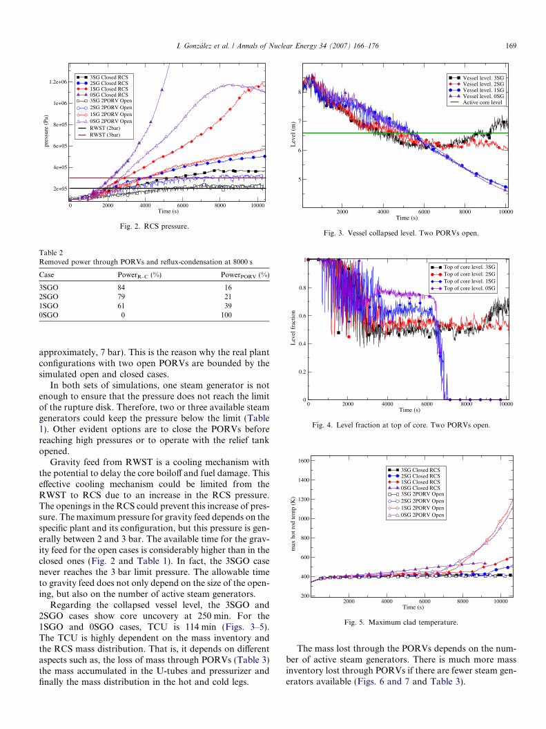
Fig. 4. Level fraction at top of core. Two PORVs open.
2000 4000 6000 8000 10000Time (s)
200
400
600
800
1000
1200
1400
1600
max
hot
rod
tem
p (K
)
3SG Closed RCS2SG Closed RCS1SG Closed RCS0SG Closed RCS3SG 2PORV Open2SG 2PORV Open1SG 2PORV Open0SG 2PORV Open
Fig. 5. Maximum clad temperature.
I. Gonzalez et al. / Annals of Nuclear Energy 34 (2007) 166–176 169
approximately, 7 bar). This is the reason why the real plantconfigurations with two open PORVs are bounded by thesimulated open and closed cases.
In both sets of simulations, one steam generator is notenough to ensure that the pressure does not reach the limitof the rupture disk. Therefore, two or three available steamgenerators could keep the pressure below the limit (Table1). Other evident options are to close the PORVs beforereaching high pressures or to operate with the relief tankopened.
Gravity feed from RWST is a cooling mechanism withthe potential to delay the core boiloff and fuel damage. Thiseffective cooling mechanism could be limited from theRWST to RCS due to an increase in the RCS pressure.The openings in the RCS could prevent this increase of pres-sure. The maximum pressure for gravity feed depends on thespecific plant and its configuration, but this pressure is gen-erally between 2 and 3 bar. The available time for the grav-ity feed for the open cases is considerably higher than in theclosed ones (Fig. 2 and Table 1). In fact, the 3SGO casenever reaches the 3 bar limit pressure. The allowable timeto gravity feed does not only depend on the size of the open-ing, but also on the number of active steam generators.
Regarding the collapsed vessel level, the 3SGO and2SGO cases show core uncovery at 250 min. For the1SGO and 0SGO cases, TCU is 114 min (Figs. 3–5).The TCU is highly dependent on the mass inventory andthe RCS mass distribution. That is, it depends on differentaspects such as, the loss of mass through PORVs (Table 3)the mass accumulated in the U-tubes and pressurizer andfinally the mass distribution in the hot and cold legs.
The mass lost through the PORVs depends on the num-ber of active steam generators. There is much more massinventory lost through PORVs if there are fewer steam gen-erators available (Figs. 6 and 7 and Table 3).
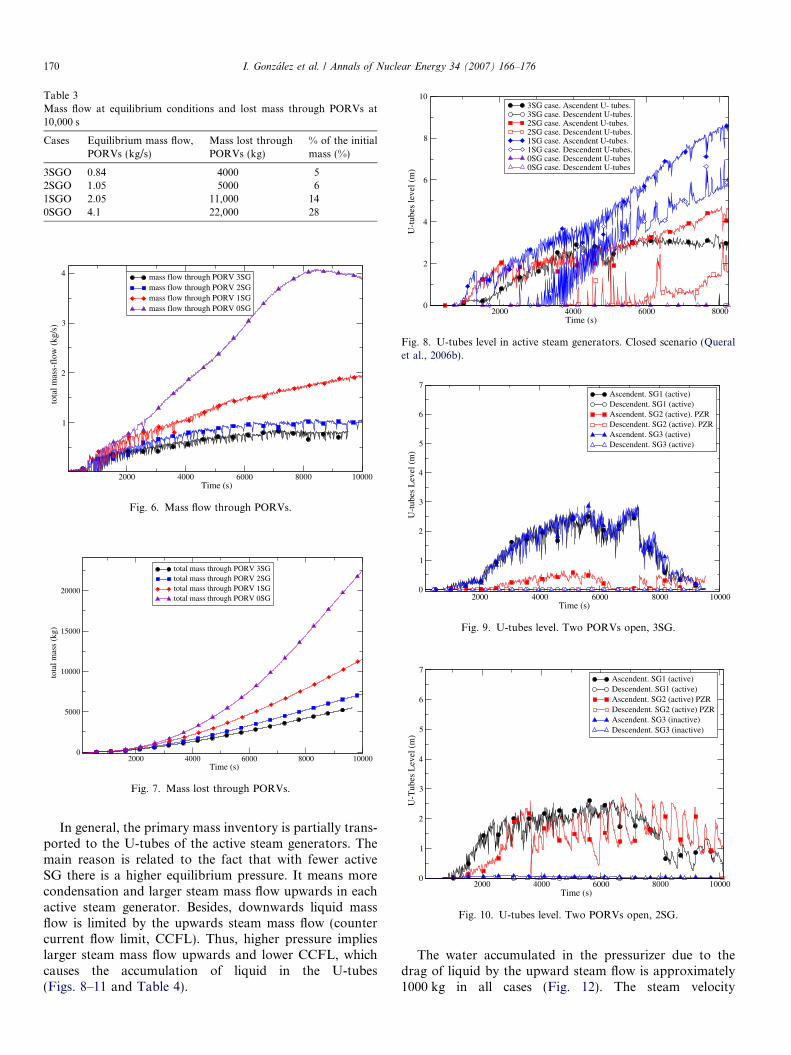
Table 3Mass flow at equilibrium conditions and lost mass through PORVs at10,000 s
Cases Equilibrium mass flow,PORVs (kg/s)
Mass lost throughPORVs (kg)
% of the initialmass (%)
3SGO 0.84 4000 52SGO 1.05 5000 61SGO 2.05 11,000 140SGO 4.1 22,000 28
2000 4000 6000 8000 10000Time (s)
1
2
3
4
tota
l mas
s-fl
ow (
kg/s
)
mass flow through PORV 3SGmass flow through PORV 2SGmass flow through PORV 1SGmass flow through PORV 0SG
Fig. 6. Mass flow through PORVs.
2000 4000 6000 8000 10000Time (s)
0
5000
10000
15000
20000
tota
l mas
s (k
g)
total mass through PORV 3SGtotal mass through PORV 2SGtotal mass through PORV 1SGtotal mass through PORV 0SG
Fig. 7. Mass lost through PORVs.
2000 4000 6000 8000Time (s)
0
2
4
6
8
10
U-t
ubes
leve
l (m
)
3SG case. Ascendent U- tubes. 3SG case. Descendent U-tubes. 2SG case. Ascendent U-tubes. 2SG case. Descendent U-tubes.1SG case. Ascendent U-tubes.1SG case. Descendent U-tubes.0SG case. Descendent U-tubes0SG case. Descendent U-tubes
Fig. 8. U-tubes level in active steam generators. Closed scenario (Queralet al., 2006b).
2000 4000 6000 8000 10000Time (s)
0
1
2
3
4
5
6
7
U-t
ubes
Lev
el (
m)
Ascendent. SG1 (active)Descendent. SG1 (active)Ascendent. SG2 (active). PZRDescendent. SG2 (active). PZRAscendent. SG3 (active)Descendent. SG3 (active)
Fig. 9. U-tubes level. Two PORVs open, 3SG.
2000 4000 6000 8000 10000Time (s)
0
1
2
3
4
5
6
7
U-T
ubes
Lev
el (
m)
Ascendent. SG1 (active)Descendent. SG1 (active) Ascendent. SG2 (active) PZRDescendent. SG2 (active) PZRAscendent. SG3 (inactive) Descendent. SG3 (inactive)
Fig. 10. U-tubes level. Two PORVs open, 2SG.
170 I. Gonzalez et al. / Annals of Nuclear Energy 34 (2007) 166–176
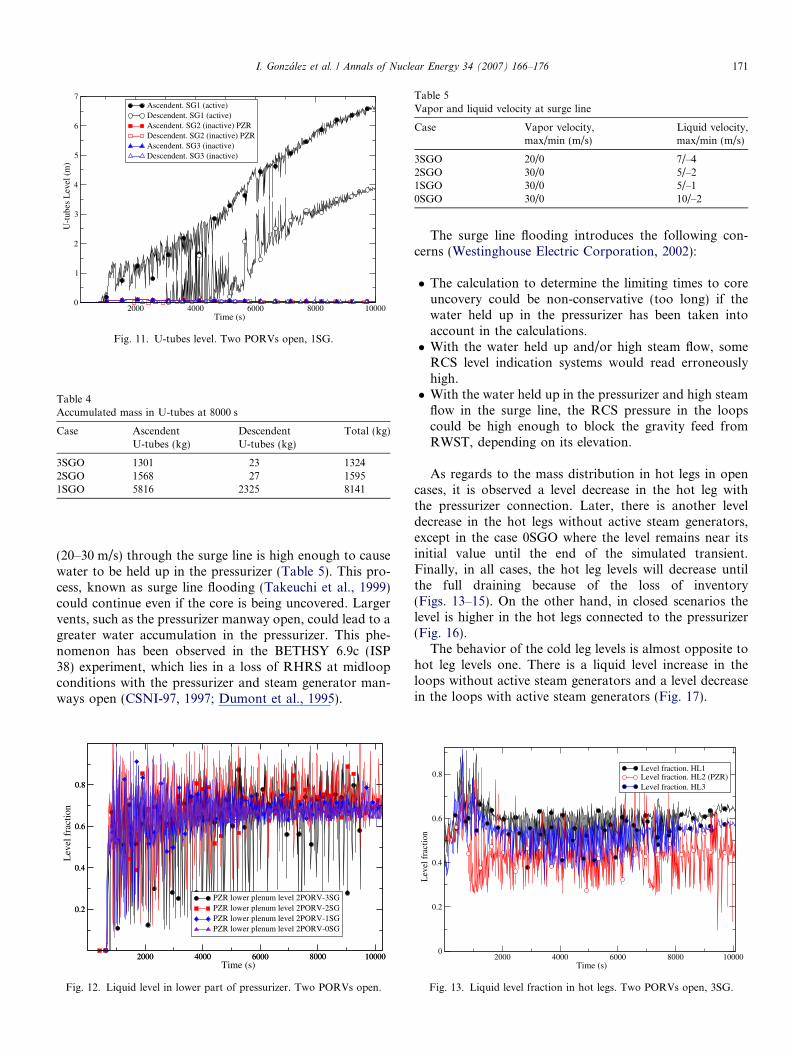
In general, the primary mass inventory is partially trans-ported to the U-tubes of the active steam generators. Themain reason is related to the fact that with fewer activeSG there is a higher equilibrium pressure. It means morecondensation and larger steam mass flow upwards in eachactive steam generator. Besides, downwards liquid massflow is limited by the upwards steam mass flow (countercurrent flow limit, CCFL). Thus, higher pressure implieslarger steam mass flow upwards and lower CCFL, whichcauses the accumulation of liquid in the U-tubes(Figs. 8–11 and Table 4).
The water accumulated in the pressurizer due to thedrag of liquid by the upward steam flow is approximately1000 kg in all cases (Fig. 12). The steam velocity
2000 4000 6000 8000 10000Time (s)
0
1
2
3
4
5
6
7
U-t
ubes
Lev
el (
m)
Ascendent. SG1 (active)Descendent. SG1 (active)Ascendent. SG2 (inactive) PZRDescendent. SG2 (inactive) PZRAscendent. SG3 (inactive)Descendent. SG3 (inactive)
Fig. 11. U-tubes level. Two PORVs open, 1SG.
Table 4Accumulated mass in U-tubes at 8000 s
Case AscendentU-tubes (kg)
DescendentU-tubes (kg)
Total (kg)
3SGO 1301 23 13242SGO 1568 27 15951SGO 5816 2325 8141
Table 5Vapor and liquid velocity at surge line
Case Vapor velocity,max/min (m/s)
Liquid velocity,max/min (m/s)
3SGO 20/0 7/–42SGO 30/0 5/–21SGO 30/0 5/–10SGO 30/0 10/–2
I. Gonzalez et al. / Annals of Nuclear Energy 34 (2007) 166–176 171
(20–30 m/s) through the surge line is high enough to causewater to be held up in the pressurizer (Table 5). This pro-cess, known as surge line flooding (Takeuchi et al., 1999)could continue even if the core is being uncovered. Largervents, such as the pressurizer manway open, could lead to agreater water accumulation in the pressurizer. This phe-nomenon has been observed in the BETHSY 6.9c (ISP38) experiment, which lies in a loss of RHRS at midloopconditions with the pressurizer and steam generator man-ways open (CSNI-97, 1997; Dumont et al., 1995).
2000 4000 6000 8000 10000Time (s)
0.2
0.4
0.6
0.8
2000 4000 6000 8000 10000
0.2
0.4
0.6
0.8
Lev
el f
ract
ion
PZR lower plenum level 2PORV-3SGPZR lower plenum level 2PORV-2SGPZR lower plenum level 2PORV-1SGPZR lower plenum level 2PORV-0SG
Fig. 12. Liquid level in lower part of pressurizer. Two PORVs open.
The surge line flooding introduces the following con-cerns (Westinghouse Electric Corporation, 2002):
� The calculation to determine the limiting times to coreuncovery could be non-conservative (too long) if thewater held up in the pressurizer has been taken intoaccount in the calculations.� With the water held up and/or high steam flow, some
RCS level indication systems would read erroneouslyhigh.� With the water held up in the pressurizer and high steam
flow in the surge line, the RCS pressure in the loopscould be high enough to block the gravity feed fromRWST, depending on its elevation.
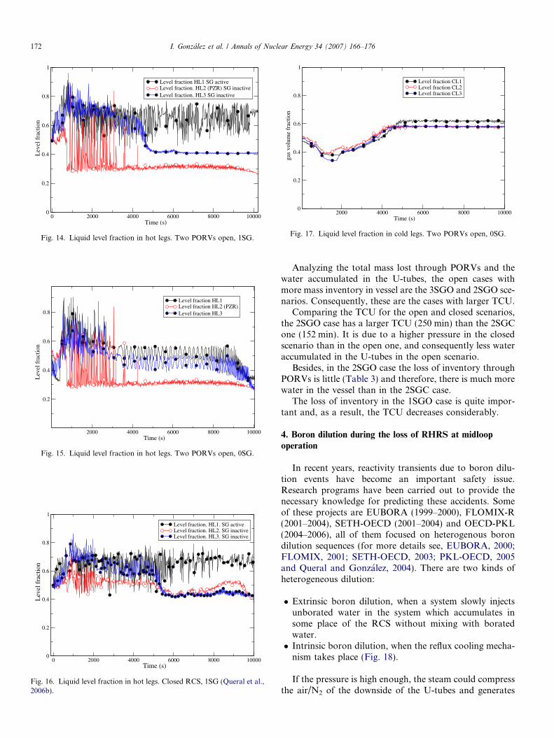
As regards to the mass distribution in hot legs in opencases, it is observed a level decrease in the hot leg withthe pressurizer connection. Later, there is another leveldecrease in the hot legs without active steam generators,except in the case 0SGO where the level remains near itsinitial value until the end of the simulated transient.Finally, in all cases, the hot leg levels will decrease untilthe full draining because of the loss of inventory(Figs. 13–15). On the other hand, in closed scenarios thelevel is higher in the hot legs connected to the pressurizer(Fig. 16).
The behavior of the cold leg levels is almost opposite tohot leg levels one. There is a liquid level increase in theloops without active steam generators and a level decreasein the loops with active steam generators (Fig. 17).
2000 4000 6000 8000 10000Time (s)
0
0.2
0.4
0.6
0.8
Lev
el f
ract
ion
Level fraction. HL1Level fraction. HL2 (PZR)Level fraction. HL3
Fig. 13. Liquid level fraction in hot legs. Two PORVs open, 3SG.
0 2000 4000 6000 8000 10000Time (s)
0
0.2
0.4
0.6
0.8
1
Lev
el f
ract
ion
Level fraction HL1 SG activeLevel fraction. HL2 (PZR) SG inactiveLevel fraction. HL3 SG inactive
Fig. 14. Liquid level fraction in hot legs. Two PORVs open, 1SG.
2000 4000 6000 8000 10000Time (s)
0.2
0.4
0.6
0.8
Lev
el f
ract
ion
Level fraction HL1Level fraction HL2 (PZR)Level fraction HL3
Fig. 15. Liquid level fraction in hot legs. Two PORVs open, 0SG.
0 2000 4000 6000 8000 10000Time (s)
0
0.2
0.4
0.6
0.8
1
Lev
el f
ract
ion
Level fraction. HL1. SG activeLevel fraction. HL2. SG inactiveLevel fraction. HL3. SG inactive
Fig. 16. Liquid level fraction in hot legs. Closed RCS, 1SG (Queral et al.,2006b).
2000 4000 6000 8000 10000Time (s)
0
0.2
0.4
0.6
0.8
1
gas
volu
me
frac
tion
Level fraction CL1 Level fraction CL2Level fraction CL3
Fig. 17. Liquid level fraction in cold legs. Two PORVs open, 0SG.
172 I. Gonzalez et al. / Annals of Nuclear Energy 34 (2007) 166–176
Analyzing the total mass lost through PORVs and thewater accumulated in the U-tubes, the open cases withmore mass inventory in vessel are the 3SGO and 2SGO sce-narios. Consequently, these are the cases with larger TCU.
Comparing the TCU for the open and closed scenarios,the 2SGO case has a larger TCU (250 min) than the 2SGCone (152 min). It is due to a higher pressure in the closedscenario than in the open one, and consequently less wateraccumulated in the U-tubes in the open scenario.
Besides, in the 2SGO case the loss of inventory throughPORVs is little (Table 3) and therefore, there is much morewater in the vessel than in the 2SGC case.
The loss of inventory in the 1SGO case is quite impor-tant and, as a result, the TCU decreases considerably.
4. Boron dilution during the loss of RHRS at midloop
operation
In recent years, reactivity transients due to boron dilu-tion events have become an important safety issue.Research programs have been carried out to provide thenecessary knowledge for predicting these accidents. Someof these projects are EUBORA (1999–2000), FLOMIX-R(2001–2004), SETH-OECD (2001–2004) and OECD-PKL(2004–2006), all of them focused on heterogenous borondilution sequences (for more details see, EUBORA, 2000;FLOMIX, 2001; SETH-OECD, 2003; PKL-OECD, 2005and Queral and Gonzalez, 2004). There are two kinds ofheterogeneous dilution:
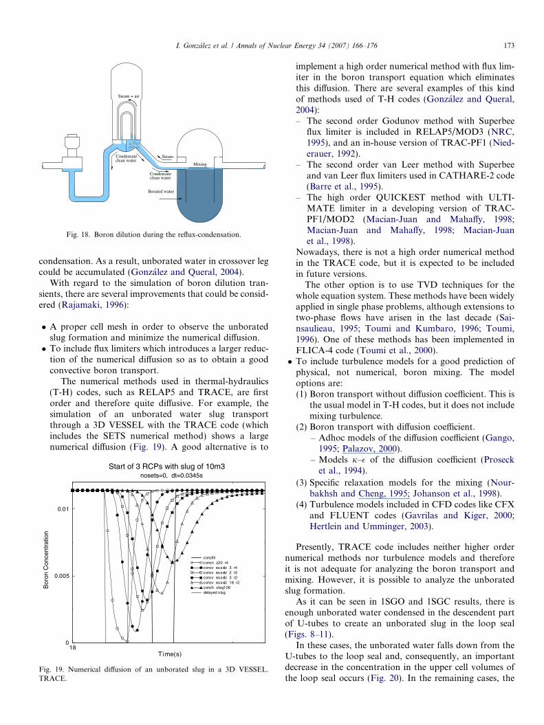
� Extrinsic boron dilution, when a system slowly injectsunborated water in the system which accumulates insome place of the RCS without mixing with boratedwater.� Intrinsic boron dilution, when the reflux cooling mecha-
nism takes place (Fig. 18).
If the pressure is high enough, the steam could compressthe air/N2 of the downside of the U-tubes and generates
Steam
Condensate
Mixing
Condensateclean water
clean water
Borated water
Steam + air
Fig. 18. Boron dilution during the reflux-condensation.
I. Gonzalez et al. / Annals of Nuclear Energy 34 (2007) 166–176 173
condensation. As a result, unborated water in crossover legcould be accumulated (Gonzalez and Queral, 2004).
With regard to the simulation of boron dilution tran-sients, there are several improvements that could be consid-ered (Rajamaki, 1996):
� A proper cell mesh in order to observe the unboratedslug formation and minimize the numerical diffusion.� To include flux limiters which introduces a larger reduc-
tion of the numerical diffusion so as to obtain a goodconvective boron transport.
The numerical methods used in thermal-hydraulics(T-H) codes, such as RELAP5 and TRACE, are firstorder and therefore quite diffusive. For example, thesimulation of an unborated water slug transportthrough a 3D VESSEL with the TRACE code (whichincludes the SETS numerical method) shows a largenumerical diffusion (Fig. 19). A good alternative is to
18Time(s)
0
0.005
0.01
Bor
on C
once
ntra
tion
Start of 3 RCPs with slug of 10m3nosets=0, dt=0.0345s
concfillconcn z20 r4concv esselz 3 r4concv esselz 2 r2concv esselz 3 r2concv esselz 18 r2conch oleg106delayed s lug
Fig. 19. Numerical diffusion of an unborated slug in a 3D VESSEL.TRACE.
implement a high order numerical method with flux lim-iter in the boron transport equation which eliminatesthis diffusion. There are several examples of this kindof methods used of T-H codes (Gonzalez and Queral,2004):– The second order Godunov method with Superbee
flux limiter is included in RELAP5/MOD3 (NRC,1995), and an in-house version of TRAC-PF1 (Nied-erauer, 1992).
– The second order van Leer method with Superbeeand van Leer flux limiters used in CATHARE-2 code(Barre et al., 1995).
– The high order QUICKEST method with ULTI-MATE limiter in a developing version of TRAC-PF1/MOD2 (Macian-Juan and Mahaffy, 1998;Macian-Juan and Mahaffy, 1998; Macian-Juanet al., 1998).
Nowadays, there is not a high order numerical methodin the TRACE code, but it is expected to be includedin future versions.
The other option is to use TVD techniques for thewhole equation system. These methods have been widelyapplied in single phase problems, although extensions totwo-phase flows have arisen in the last decade (Sai-nsaulieau, 1995; Toumi and Kumbaro, 1996; Toumi,1996). One of these methods has been implemented inFLICA-4 code (Toumi et al., 2000).� To include turbulence models for a good prediction of
physical, not numerical, boron mixing. The modeloptions are:(1) Boron transport without diffusion coefficient. This is
the usual model in T-H codes, but it does not includemixing turbulence.
(2) Boron transport with diffusion coefficient.– Adhoc models of the diffusion coefficient (Gango,
1995; Palazov, 2000).– Models j–� of the diffusion coefficient (Proseck
et al., 1994).
(3) Specific relaxation models for the mixing (Nour-bakhsh and Cheng, 1995; Johanson et al., 1998).
(4) Turbulence models included in CFD codes like CFXand FLUENT codes (Gavrilas and Kiger, 2000;Hertlein and Umminger, 2003).
Presently, TRACE code includes neither higher ordernumerical methods nor turbulence models and thereforeit is not adequate for analyzing the boron transport andmixing. However, it is possible to analyze the unboratedslug formation.
As it can be seen in 1SGO and 1SGC results, there isenough unborated water condensed in the descendent partof U-tubes to create an unborated slug in the loop seal(Figs. 8–11).
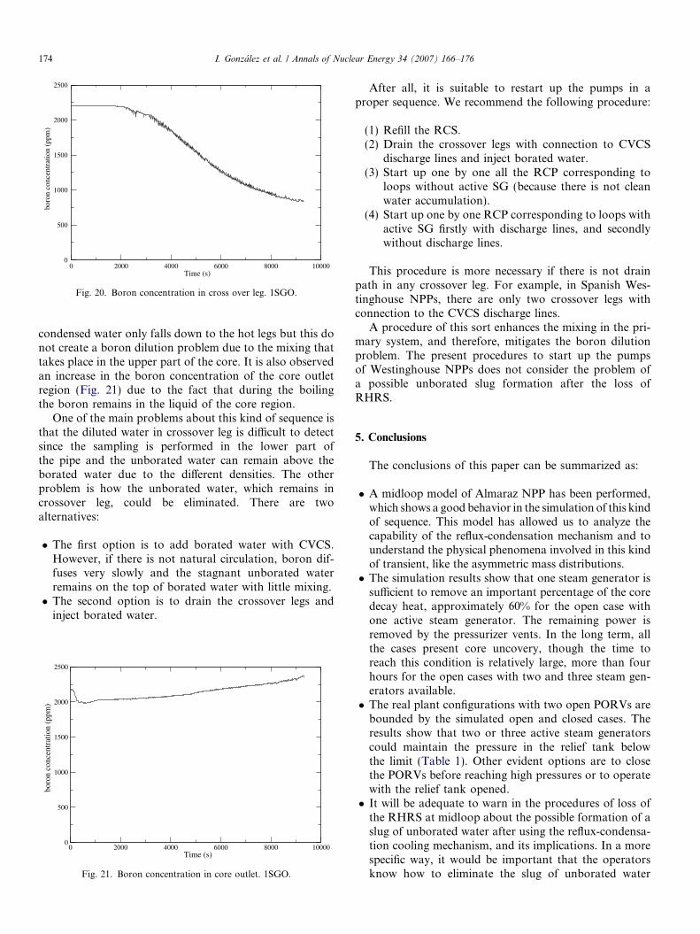
In these cases, the unborated water falls down from theU-tubes to the loop seal and, consequently, an importantdecrease in the concentration in the upper cell volumes ofthe loop seal occurs (Fig. 20). In the remaining cases, the
0 2000 4000 6000 8000 10000Time (s)
0
500
1000
1500
2000
2500
boro
n co
ncen
trat
ion
(ppm
)
Fig. 20. Boron concentration in cross over leg. 1SGO.
174 I. Gonzalez et al. / Annals of Nuclear Energy 34 (2007) 166–176
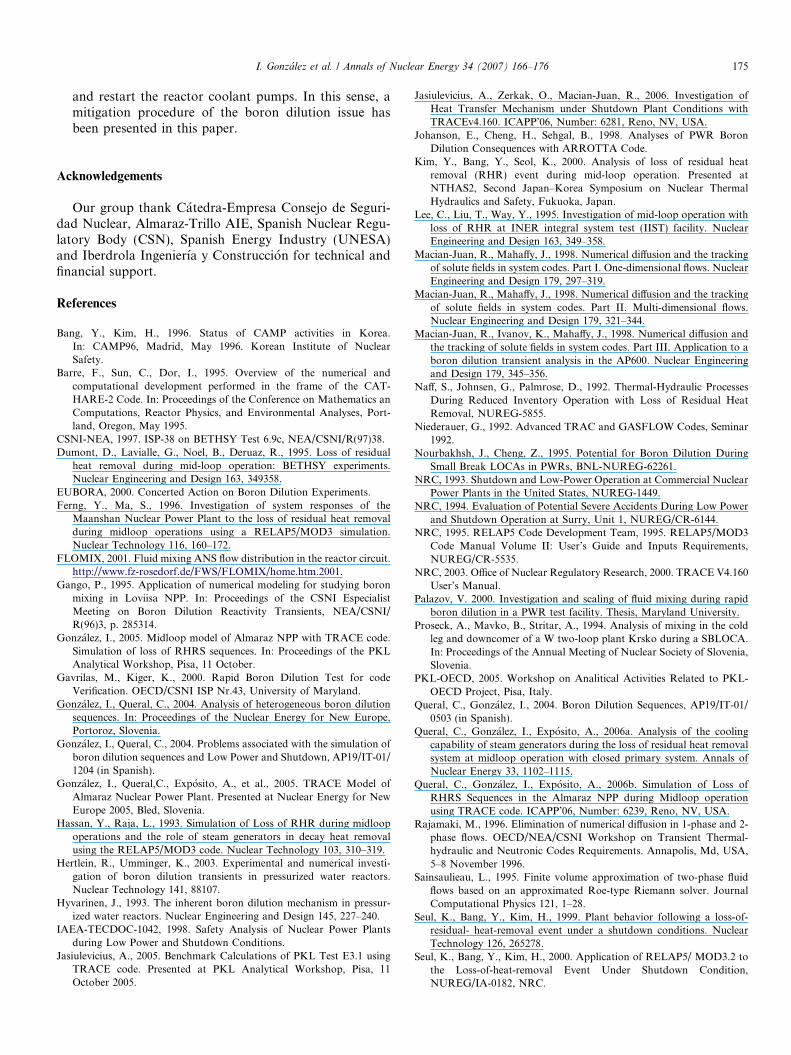
condensed water only falls down to the hot legs but this donot create a boron dilution problem due to the mixing thattakes place in the upper part of the core. It is also observedan increase in the boron concentration of the core outletregion (Fig. 21) due to the fact that during the boilingthe boron remains in the liquid of the core region.
One of the main problems about this kind of sequence isthat the diluted water in crossover leg is difficult to detectsince the sampling is performed in the lower part ofthe pipe and the unborated water can remain above theborated water due to the different densities. The otherproblem is how the unborated water, which remains incrossover leg, could be eliminated. There are twoalternatives:
� The first option is to add borated water with CVCS.However, if there is not natural circulation, boron dif-fuses very slowly and the stagnant unborated waterremains on the top of borated water with little mixing.� The second option is to drain the crossover legs and
inject borated water.
0 2000 4000 6000 8000 10000Time (s)
0
500
1000
1500
2000
2500
boro
n co
ncen
trat
ion
(ppm
)
Fig. 21. Boron concentration in core outlet. 1SGO.
After all, it is suitable to restart up the pumps in aproper sequence. We recommend the following procedure:
(1) Refill the RCS.(2) Drain the crossover legs with connection to CVCS
discharge lines and inject borated water.(3) Start up one by one all the RCP corresponding to
loops without active SG (because there is not cleanwater accumulation).
(4) Start up one by one RCP corresponding to loops withactive SG firstly with discharge lines, and secondlywithout discharge lines.
This procedure is more necessary if there is not drainpath in any crossover leg. For example, in Spanish Wes-tinghouse NPPs, there are only two crossover legs withconnection to the CVCS discharge lines.
A procedure of this sort enhances the mixing in the pri-mary system, and therefore, mitigates the boron dilutionproblem. The present procedures to start up the pumpsof Westinghouse NPPs does not consider the problem ofa possible unborated slug formation after the loss ofRHRS.
5. Conclusions
The conclusions of this paper can be summarized as:
� A midloop model of Almaraz NPP has been performed,which shows a good behavior in the simulation of this kindof sequence. This model has allowed us to analyze thecapability of the reflux-condensation mechanism and tounderstand the physical phenomena involved in this kindof transient, like the asymmetric mass distributions.� The simulation results show that one steam generator is
sufficient to remove an important percentage of the coredecay heat, approximately 60% for the open case withone active steam generator. The remaining power isremoved by the pressurizer vents. In the long term, allthe cases present core uncovery, though the time toreach this condition is relatively large, more than fourhours for the open cases with two and three steam gen-erators available.� The real plant configurations with two open PORVs are
bounded by the simulated open and closed cases. Theresults show that two or three active steam generatorscould maintain the pressure in the relief tank belowthe limit (Table 1). Other evident options are to closethe PORVs before reaching high pressures or to operatewith the relief tank opened.� It will be adequate to warn in the procedures of loss of
the RHRS at midloop about the possible formation of aslug of unborated water after using the reflux-condensa-tion cooling mechanism, and its implications. In a morespecific way, it would be important that the operatorsknow how to eliminate the slug of unborated water
I. Gonzalez et al. / Annals of Nuclear Energy 34 (2007) 166–176 175
and restart the reactor coolant pumps. In this sense, amitigation procedure of the boron dilution issue hasbeen presented in this paper.
Acknowledgements
Our group thank Catedra-Empresa Consejo de Seguri-dad Nuclear, Almaraz-Trillo AIE, Spanish Nuclear Regu-latory Body (CSN), Spanish Energy Industry (UNESA)and Iberdrola Ingenierıa y Construccion for technical andfinancial support.
References
Bang, Y., Kim, H., 1996. Status of CAMP activities in Korea.In: CAMP96, Madrid, May 1996. Korean Institute of NuclearSafety.
Barre, F., Sun, C., Dor, I., 1995. Overview of the numerical andcomputational development performed in the frame of the CAT-HARE-2 Code. In: Proceedings of the Conference on Mathematics anComputations, Reactor Physics, and Environmental Analyses, Port-land, Oregon, May 1995.
CSNI-NEA, 1997. ISP-38 on BETHSY Test 6.9c, NEA/CSNI/R(97)38.Dumont, D., Lavialle, G., Noel, B., Deruaz, R., 1995. Loss of residual
heat removal during mid-loop operation: BETHSY experiments.Nuclear Engineering and Design 163, 349358.
EUBORA, 2000. Concerted Action on Boron Dilution Experiments.Ferng, Y., Ma, S., 1996. Investigation of system responses of the
Maanshan Nuclear Power Plant to the loss of residual heat removalduring midloop operations using a RELAP5/MOD3 simulation.Nuclear Technology 116, 160–172.
FLOMIX, 2001. Fluid mixing ANS flow distribution in the reactor circuit.http://www.fz-rosedorf.de/FWS/FLOMIX/home.htm.2001.
Gango, P., 1995. Application of numerical modeling for studying boronmixing in Loviisa NPP. In: Proceedings of the CSNI EspecialistMeeting on Boron Dilution Reactivity Transients, NEA/CSNI/R(96)3, p. 285314.
Gonzalez, I., 2005. Midloop model of Almaraz NPP with TRACE code.Simulation of loss of RHRS sequences. In: Proceedings of the PKLAnalytical Workshop, Pisa, 11 October.
Gavrilas, M., Kiger, K., 2000. Rapid Boron Dilution Test for codeVerification. OECD/CSNI ISP Nr.43, University of Maryland.
Gonzalez, I., Queral, C., 2004. Analysis of heterogeneous boron dilutionsequences. In: Proceedings of the Nuclear Energy for New Europe,Portoroz, Slovenia.
Gonzalez, I., Queral, C., 2004. Problems associated with the simulation ofboron dilution sequences and Low Power and Shutdown, AP19/IT-01/1204 (in Spanish).
Gonzalez, I., Queral,C., Exposito, A., et al., 2005. TRACE Model ofAlmaraz Nuclear Power Plant. Presented at Nuclear Energy for NewEurope 2005, Bled, Slovenia.
Hassan, Y., Raja, L., 1993. Simulation of Loss of RHR during midloopoperations and the role of steam generators in decay heat removalusing the RELAP5/MOD3 code. Nuclear Technology 103, 310–319.
Hertlein, R., Umminger, K., 2003. Experimental and numerical investi-gation of boron dilution transients in pressurized water reactors.Nuclear Technology 141, 88107.
Hyvarinen, J., 1993. The inherent boron dilution mechanism in pressur-ized water reactors. Nuclear Engineering and Design 145, 227–240.
IAEA-TECDOC-1042, 1998. Safety Analysis of Nuclear Power Plantsduring Low Power and Shutdown Conditions.
Jasiulevicius, A., 2005. Benchmark Calculations of PKL Test E3.1 usingTRACE code. Presented at PKL Analytical Workshop, Pisa, 11October 2005.
Jasiulevicius, A., Zerkak, O., Macian-Juan, R., 2006. Investigation ofHeat Transfer Mechanism under Shutdown Plant Conditions withTRACEv4.160. ICAPP’06, Number: 6281, Reno, NV, USA.
Johanson, E., Cheng, H., Sehgal, B., 1998. Analyses of PWR BoronDilution Consequences with ARROTTA Code.
Kim, Y., Bang, Y., Seol, K., 2000. Analysis of loss of residual heatremoval (RHR) event during mid-loop operation. Presented atNTHAS2, Second Japan–Korea Symposium on Nuclear ThermalHydraulics and Safety, Fukuoka, Japan.
Lee, C., Liu, T., Way, Y., 1995. Investigation of mid-loop operation withloss of RHR at INER integral system test (IIST) facility. NuclearEngineering and Design 163, 349–358.
Macian-Juan, R., Mahaffy, J., 1998. Numerical diffusion and the trackingof solute fields in system codes. Part I. One-dimensional flows. NuclearEngineering and Design 179, 297–319.
Macian-Juan, R., Mahaffy, J., 1998. Numerical diffusion and the trackingof solute fields in system codes. Part II. Multi-dimensional flows.Nuclear Engineering and Design 179, 321–344.
Macian-Juan, R., Ivanov, K., Mahaffy, J., 1998. Numerical diffusion andthe tracking of solute fields in system codes. Part III. Application to aboron dilution transient analysis in the AP600. Nuclear Engineeringand Design 179, 345–356.
Naff, S., Johnsen, G., Palmrose, D., 1992. Thermal-Hydraulic ProcessesDuring Reduced Inventory Operation with Loss of Residual HeatRemoval, NUREG-5855.
Niederauer, G., 1992. Advanced TRAC and GASFLOW Codes, Seminar1992.
Nourbakhsh, J., Cheng, Z., 1995. Potential for Boron Dilution DuringSmall Break LOCAs in PWRs, BNL-NUREG-62261.
NRC, 1993. Shutdown and Low-Power Operation at Commercial NuclearPower Plants in the United States, NUREG-1449.
NRC, 1994. Evaluation of Potential Severe Accidents During Low Powerand Shutdown Operation at Surry, Unit 1, NUREG/CR-6144.
NRC, 1995. RELAP5 Code Development Team, 1995. RELAP5/MOD3Code Manual Volume II: User’s Guide and Inputs Requirements,NUREG/CR-5535.
NRC, 2003. Office of Nuclear Regulatory Research, 2000. TRACE V4.160User’s Manual.
Palazov, V. 2000. Investigation and scaling of fluid mixing during rapidboron dilution in a PWR test facility. Thesis, Maryland University.
Proseck, A., Mavko, B., Stritar, A., 1994. Analysis of mixing in the coldleg and downcomer of a W two-loop plant Krsko during a SBLOCA.In: Proceedings of the Annual Meeting of Nuclear Society of Slovenia,Slovenia.
PKL-OECD, 2005. Workshop on Analitical Activities Related to PKL-OECD Project, Pisa, Italy.
Queral, C., Gonzalez, I., 2004. Boron Dilution Sequences, AP19/IT-01/0503 (in Spanish).
Queral, C., Gonzalez, I., Exposito, A., 2006a. Analysis of the coolingcapability of steam generators during the loss of residual heat removalsystem at midloop operation with closed primary system. Annals ofNuclear Energy 33, 1102–1115.
Queral, C., Gonzalez, I., Exposito, A., 2006b. Simulation of Loss ofRHRS Sequences in the Almaraz NPP during Midloop operationusing TRACE code. ICAPP’06, Number: 6239, Reno, NV, USA.
Rajamaki, M., 1996. Elimination of numerical diffusion in 1-phase and 2-phase flows. OECD/NEA/CSNI Workshop on Transient Thermal-hydraulic and Neutronic Codes Requirements. Annapolis, Md, USA,5–8 November 1996.
Sainsaulieau, L., 1995. Finite volume approximation of two-phase fluidflows based on an approximated Roe-type Riemann solver. JournalComputational Physics 121, 1–28.
Seul, K., Bang, Y., Kim, H., 1999. Plant behavior following a loss-of-residual- heat-removal event under a shutdown conditions. NuclearTechnology 126, 265278.
Seul, K., Bang, Y., Kim, H., 2000. Application of RELAP5/ MOD3.2 tothe Loss-of-heat-removal Event Under Shutdown Condition,NUREG/IA-0182, NRC.

176 I. Gonzalez et al. / Annals of Nuclear Energy 34 (2007) 166–176
SETH-OECD, 2003. In: First Workshop on Analitical Activities Relatedto SETH-OECD Project, Barcelona, Spain.
Takeuchi, K., Young, M., Gagnon, A., 1999. Flooding in the pressurizersurge line of AP600 plant and analyses of APEX data. NuclearEngineering and Design 192, 45–48.
Toumi, I., Kumbaro, A., 1996. An approximate linearized Riemann solverfor a two fluid-model. Journal Computational Physics 124, 286–300.
Toumi, I., 1996. An upwind numerical method for two-fluid tow-phasemodels. Nuclear Science and Engineering 123, 147–168.
Toumi, I., Bergeron, A., Gallo, D., Royer, E., Caruge, D., 2000. FLICA-4: a three dimensional two-phase flow computer code with advancednumerical methods for nuclear applications. Nuclear Engineering andDesign 200, 139–155.
Westinghouse Electric Corporation, 2002. Sequoyah Units 1 and 2.Notification to TVA that Westinghouse has identified a potential issuerelated to limitations of pressurizer ventig for decay heat removal atcold shutdown (ADAMS Ref. ML013380174).
Related Documents