Phase Series Doc. Code: CE115100 Revision: I Altus S. A. 1 Product Description Phase Series provides to the market solutions for several application sorts where the need for electrical power and energy measurements and monitoring exists. Through PH3100 Multifunction Power Meter is possible to measure real time data such as: voltage, current, power (active, reactive and apparent), power factor, phase angle, demand of active and reactive power and more. Using the communication interface, the Multifunction Power Meter turns possible the energy consumption monitoring in several applications like energy sharing of residential and commercial buildings, shopping centers or any applications that needs the monitoring of several variables in a single device. Furthermore Phase Series provides a group of extension modules that can be connected to PH3100 which are the following: ETHERNET and PROFIBUS communication, mass memory module with integrated harmonics analysis and a digital output module based on relays output. The picture shows the product with some measurements on display. PH3100 Multifunction Power Meter module has the following features: LCD display Line and phase voltage measurement Neutral and phase current measurement Active/reactive/apparent power and power factor measurement Active and reactive energy measurement Measurement class in accordance with IEC 60687 RS-485 communication port (for configuration) MODBUS RTU communication protocol 2 isolated opto-coupled pulsed energy output (active and reactive energy) Measurements average value calculation Record of maximum and minimum values measured 2 GB Mass memory and harmonic analysis (optional) ETHERNET communication port (optional) PROFIBUS-DP communication port (optional) 4 digital outputs module (optional) Ordering Information Included Items The product package contains the following items: Multifunction Power Meter (PH3100) or expansion module PH3120/PH3131/PH3150 or PH3151) 2 GB SD Card (included only with the PH3131) Connector 9 positions (included only with the PH3120) Connector 14 positions (included only with the PH3100) 2 clamps for fixing to the panel (included only with the PH3100) Installation guides Product Code The following code should be used to purchase the product: Code Denomination PH3100 Multifunction Power Meter PH3101 Multifunction Power Meter Configuration Software PH3120 4 Digital Outputs Module PH3220 Power Meter with 4 Digital Outputs PH3131 Mass Memory and Harmonics Analyzer Module PH3231 Power Meter with Mass Memory and Harmonics Analyzer PH3150 ETHERNET Module PH3250 Power Meter with ETHERNET PH3151 PROFIBUS Module PH3251 Power Meter with PROFIBUS

Welcome message from author
This document is posted to help you gain knowledge. Please leave a comment to let me know what you think about it! Share it to your friends and learn new things together.
Transcript
Phase Series
Doc. Code: CE115100 Revision: I
Altus S. A. 1
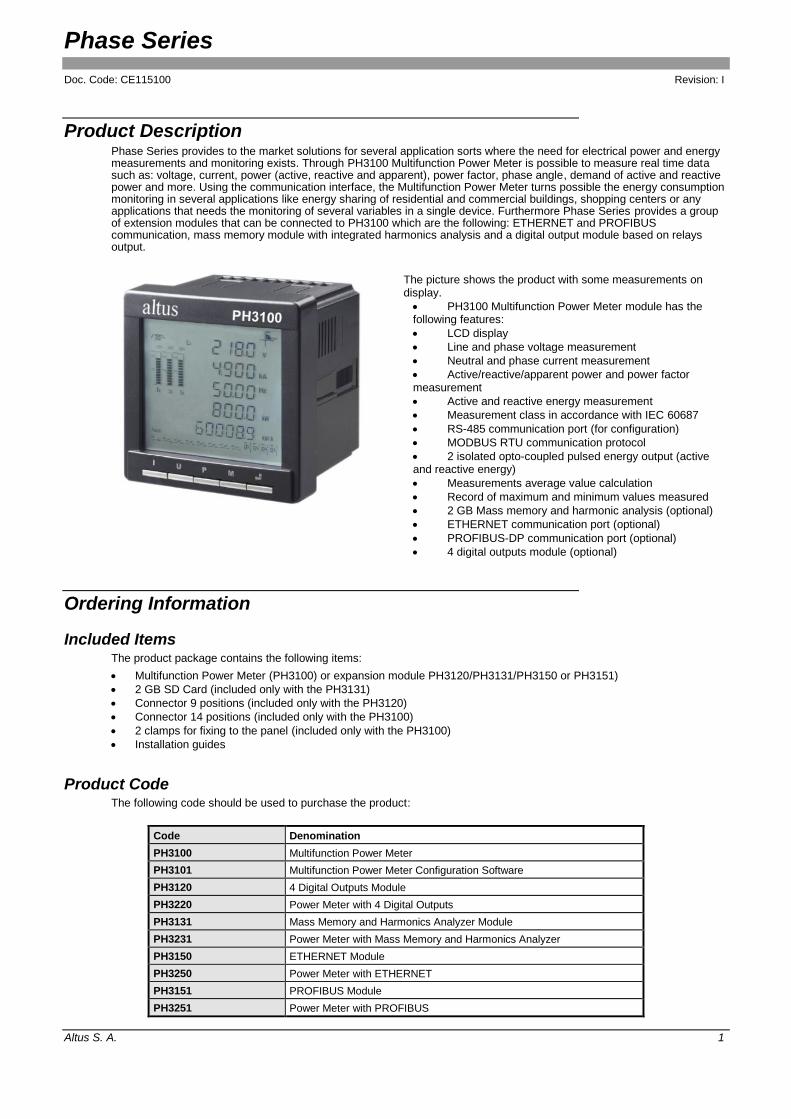
Product Description Phase Series provides to the market solutions for several application sorts where the need for electrical power and energy measurements and monitoring exists. Through PH3100 Multifunction Power Meter is possible to measure real time data such as: voltage, current, power (active, reactive and apparent), power factor, phase angle, demand of active and reactive power and more. Using the communication interface, the Multifunction Power Meter turns possible the energy consumption monitoring in several applications like energy sharing of residential and commercial buildings, shopping centers or any applications that needs the monitoring of several variables in a single device. Furthermore Phase Series provides a group of extension modules that can be connected to PH3100 which are the following: ETHERNET and PROFIBUS communication, mass memory module with integrated harmonics analysis and a digital output module based on relays output.
The picture shows the product with some measurements on display.
PH3100 Multifunction Power Meter module has the following features:
LCD display
Line and phase voltage measurement
Neutral and phase current measurement
Active/reactive/apparent power and power factor measurement
Active and reactive energy measurement
Measurement class in accordance with IEC 60687
RS-485 communication port (for configuration)
MODBUS RTU communication protocol
2 isolated opto-coupled pulsed energy output (active and reactive energy)
Measurements average value calculation
Record of maximum and minimum values measured
2 GB Mass memory and harmonic analysis (optional)
ETHERNET communication port (optional)
PROFIBUS-DP communication port (optional)
4 digital outputs module (optional)
Ordering Information
Included Items The product package contains the following items:
Multifunction Power Meter (PH3100) or expansion module PH3120/PH3131/PH3150 or PH3151)
2 GB SD Card (included only with the PH3131)
Connector 9 positions (included only with the PH3120)
Connector 14 positions (included only with the PH3100)
2 clamps for fixing to the panel (included only with the PH3100)
Installation guides
Product Code The following code should be used to purchase the product:
Code Denomination
PH3100 Multifunction Power Meter
PH3101 Multifunction Power Meter Configuration Software
PH3120 4 Digital Outputs Module
PH3220 Power Meter with 4 Digital Outputs
PH3131 Mass Memory and Harmonics Analyzer Module
PH3231 Power Meter with Mass Memory and Harmonics Analyzer
PH3150 ETHERNET Module
PH3250 Power Meter with ETHERNET
PH3151 PROFIBUS Module
PH3251 Power Meter with PROFIBUS

Phase Series
Doc. Code: CE115100 Revision: I
Altus S. A. 2
Notes:
PH3100: PH3100 Multifunction Power Meter from Phase Series is equipment used for power and energy measurements. This product measures electrical real time data, such as: voltage, current, power (active, reactive and apparent), power factor, phase angle and demand of active and reactive power. Using the communication interface, the Multifunction Power Meter turns possible the energy consumption monitoring in several applications like energy sharing of residential and commercial buildings, shopping centers or any applications that needs the monitoring of several variables in a single device. The PH3100 allows connecting together a communication module (PH3150 or PH3151), a digital output module (PH3120) and a mass memory module (PH3131).
PH3101: PH3100 configuration software allows the multifunction device and its expansion modules configuration. It also has some monitoring functions. The software is available at www.altus.com.br.
PH3120: The 4 digital output module is used for signalization of events that occur during PH3100’s electrical values monitoring time, or even for source up to 5-A loads. The events, responsible for the digital outputs control, are completely programmable and have 15 signalization functions. In addition, it’s possible to configure delay time for the output activation and the activation signal permanency as well.
PH3131: The mass memory and harmonic analyzer module allows the record of the electrical values measured by the multifunction power meter and the signal harmonic distortion in a unique modules. The period between samples is configurable and the storage capacity is beyond market standard, allowing the record of, about, 10 years with no need for data uploading. The module turns possible the harmonic measurement from 2nd to 63rd. The PH3101 software, available at www.altus.com.br, allows graphic visualization of each harmonic intensity and data conversion from the mass memory to an electronic sheet.
PH3150: Through the ETHERNET communication module the multifunction power meter can be connected to a computer network and use a programmable controller to monitor it or even use a computer with a supervisory application. The available protocol for this application is the MODBUS RTU over TCP/IP.
PH3151: Through the PROFIBUS-DP communication module the Multifunction Power Meter can access measurements using this protocol, allowing the monitoring by a programmable controller or a supervisory system which uses the same protocol.
PH3220, PH3231, PH3250 and PH3251: Each one of these products is a combination of a multimeter and its respective expansion module. The features of each expansion module remain the same. However, from revision AG onwards of the PH3100 multimeter, it is possible to use one or more expansion modules, making the previously available combined sets obsolete.
Related Products The following products must be purchased separately when necessary:
Code Denomination
AL-2306 RS-485 network cable (up to 500 meters)
AL-2301 RS-485 network cable (up to 1000 meters)
PO8525 RS-485 network connector and terminator
AL-2600 RS-485 network connector and terminator
FBS-CM25C Serial interface Module 1 x RS-232 and 1 x RS-485
Notes:
AL-2306: Shielded twisted pair cable without connector intended to be used on RS-485 networks. This cable allows the connection between PH3100 and AL-1413, Al-2600, FBS-CM25C, PO8525 or any other RS-485 compatible product. This cable can reach lengths of up to 500 meters. When longer cables are required AL-2301 must be used.
AL-2301: Two pairs shielded twisted cable with no connectors, used for networks based on RS-485 interface, as an interconnection on a network between two or more AL-2600 or PO8525, with 1000m of maximum length.
PO8525: RS-485 network connector/terminator module. For each connection point there must be a PO8525. On the RJ45 connector from PO8525, the Ponto series (or DUO series) RS-485 communication interface series must be plugged. The PO8525 placed at the network extremities must be configured as terminators, the rest as connection point.
AL-2600: RS-485 network connector/terminator module. It is used to make possible the AL-2306 cable interconnection with the AL-2000 Series and QUARK PLCs and also to provide the RS-485 network termination, preventing signals reflection problems.
FBS-CM25C: FBS-CM25C is a RS-232/RS-485 converter that has an identified connector block for RS-485 and a DB9 connector used for RS-232 communication, allowing the connection of the Multifunction Power Meter to computers with standard serial interface. To connect the PH3100 on this converter, the AL-2301 or the AL-2306 cable must be used.

Phase Series
Doc. Code: CE115100 Revision: I
Altus S. A. 3
General Features
PH3100
Module type Multifunction Power Meter
Current Phase current, average phase current and neutral current measurements
Phase voltage Phase voltage and average phase voltage measurements
Line voltage Line voltage and average line voltage measurements
Active power Phase active power and load active power measurements
Reactive power Phase reactive power and load reactive power measurements
Apparent power Phase apparent power and load apparent total power measurements
Frequency Frequency measurement
Power factor Load and phase power factor measurements
Demand 3-phase active (kW) / reactive (kVAr) power demand, apparent (kVA) power demand
Active energy Imported, exported and net active energy
Reactive energy Imported, exported and net reactive energy
Energy pulse output - 1 active energy pulse output
- 1 reactive energy pulse output
Real time display Year/month/day/hour/minute/second
Serial programming port Yes
Operation temperature 0 to 60 °C (PH3100 with one expansion module)
0 to 55 ºC (PH3100 with two expansion module)
0 to 50 ºC (PH3100 with three expansion module)
Storage temperature -20 to 75 ºC
Operation humidity 5 to 95% no condensation
IP Level IP 30
Dimensions (W x H x D) 96 x 96 x 85 mm
Limits and Measurement Class
Measurement Limits Measurement Class
Voltage 0 to 9999.9 kV 0.2
Current 0 to 9999.9 kA 0.2
Power factor -1 to +1 1.0
Frequency 45 to 65 Hz 0.01
Active power -9999 to 9999 MW 0.5
Reactive power -9999 to 9999 MVAr 0.5
Apparent power 0 to 9999 MVA 0.5
Active demand -9999 to 9999 MW 1.0
Reactive demand -9999 to 9999 MVAr 1.0
Active energy 0 to 99999999.99 MWh 0.5
Reactive energy 0 to 99999999.99 MVArh 1.0
Phase angle 0.0º to 359.9º 2.0
Total harmonic current 0 to 100% 2.0
Total harmonic voltage 0 to 100% 2.0
Note:
The measurement limits are related to the calculation and exhibition; these limits don’t correspond to the inputs’ electrical limits.

Phase Series
Doc. Code: CE115100 Revision: I
Altus S. A. 4
Electrical Features PH3100
Input current
Measurement range
Power consumption
Continuous maximum current
Non continuous maximum current
0 to 5 A
0.5% to 120% of nominal input current
Lower than 0.2 VA per phase
Two times the nominal input current
100 A per 1 second
Input voltage
Frequency
Measurement range
Power consumption
Continuous maximum voltage
Non continuous maximum voltage
0 to 400 Vac (phase), 0 to 693 Vac (line)
45 to 65 Hz
3% to 120% of nominal input voltage
Lower than 0.5 VA per phase
Two times the nominal input voltage
2500 Vac per 1 second
Power Input 85 to 265 Vac or Vdc
Consumption Lower than 8 VA
Isolation
Between outputs and logic
Between power and logic
Between current inputs and logic
1500 Vac per 1 minute
1500 Vac per 1 minute
1500 Vac per 1 minute
Energy Pulse Outputs PH3100
Number of common outputs 2 pulse outputs, divided:
EP – 1 output – active energy
EQ – 1 output – reactive energy
Maximum current per point 15 mA
Output type Sink or source opto-coupled
Operation voltage 0 a 30 Vdc
Isolation 1500 Vac per1 minute between outputs and logic circuit
Pin setup Position 11 – collector (positive) EP output
Position 12 – emitter (negative) EP output
Position 13 – collector (positive) EQ output
Position 14 – emitter (negative) EQ output
Notes:
Maximum current per point: the opto-coupled outputs are not protected against over current. The use of an external fuse is recommended in order to protect the output.
Output type: the output can be of sink or source type, depending on the user’s installation.
Pin setup: observe the output polarization (positive collector and negative emitter). In case of reverse polarization, the output can be damaged.
RS-485 Serial Channel PH3100
Physical layer RS-485
Protocol MODBUS RTU
Internal termination No
Insulation with logical circuit No
Baud rate 2400 / 4800 / 9600 / 19200 / 38400 bps
Connector Position 15 – TX+
Position 16 – TX-
Position 17 – Shield
Phase Series
Doc. Code: CE115100 Revision: I
Altus S. A. 5
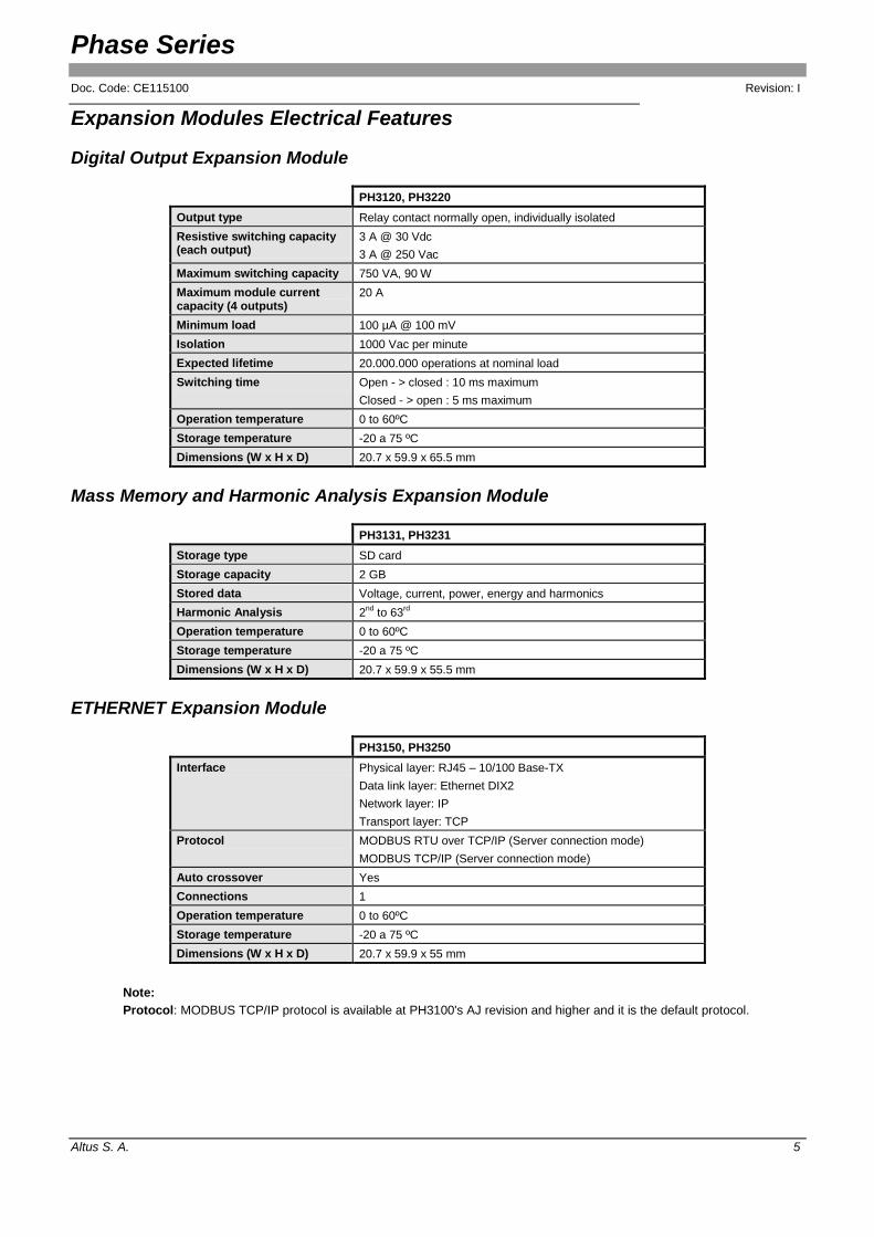
Expansion Modules Electrical Features
Digital Output Expansion Module
PH3120, PH3220
Output type Relay contact normally open, individually isolated
Resistive switching capacity (each output)
3 A @ 30 Vdc
3 A @ 250 Vac
Maximum switching capacity 750 VA, 90 W
Maximum module current capacity (4 outputs)
20 A
Minimum load 100 µA @ 100 mV
Isolation 1000 Vac per minute
Expected lifetime 20.000.000 operations at nominal load
Switching time Open - > closed : 10 ms maximum
Closed - > open : 5 ms maximum
Operation temperature 0 to 60ºC
Storage temperature -20 a 75 ºC
Dimensions (W x H x D) 20.7 x 59.9 x 65.5 mm
Mass Memory and Harmonic Analysis Expansion Module
PH3131, PH3231
Storage type SD card
Storage capacity 2 GB
Stored data Voltage, current, power, energy and harmonics
Harmonic Analysis 2nd
to 63rd
Operation temperature 0 to 60ºC
Storage temperature -20 a 75 ºC
Dimensions (W x H x D) 20.7 x 59.9 x 55.5 mm
ETHERNET Expansion Module
PH3150, PH3250
Interface Physical layer: RJ45 – 10/100 Base-TX
Data link layer: Ethernet DIX2
Network layer: IP
Transport layer: TCP
Protocol MODBUS RTU over TCP/IP (Server connection mode)
MODBUS TCP/IP (Server connection mode)
Auto crossover Yes
Connections 1
Operation temperature 0 to 60ºC
Storage temperature -20 a 75 ºC
Dimensions (W x H x D) 20.7 x 59.9 x 55 mm
Note:
Protocol: MODBUS TCP/IP protocol is available at PH3100's AJ revision and higher and it is the default protocol.

Phase Series
Doc. Code: CE115100 Revision: I
Altus S. A. 6
PROFIBUS Expansion Module
PH3151, PH3251
Channels 1
Baud rate Baud rate auto detection 9.6 to 12000 kbit/s
Protocol PROFIBUS DP Slave
Operation temperature 0 to 60ºC
Storage temperature -20 a 75 ºC
Dimensions (W x H x D) 20.7 x 59.9 x 56.5 mm
ATTENTION: For further details about the use of more than one expansion module at the same time, please consult Technical Support. To remove the SD card, you should power off the multifunction power meter to avoid risk of electric shock.
Compatibility with Other Products The expansion modules in your reviews combined with the PH3100 are compatible between the following product reviews:
Compatibility between revisions
PH3100 AA to AF AG to AJ AK or higher
PH3120 - AA or higher
PH3131 - AA to AB AC or higher
PH3150 - AA to AB AC or higher
PH3151 - AA or higher
PH3101 (version) 2.0.7 or higher 2.20 or higher
The expansion modules in the combined versions are compatible with these versions:
PH3100 – Multifunction Power Meter, revision AE or higher.
PH3101 – PH3100 Configuration software, version 1.7.0 or higher.
ATTENTION: From PH3100's AJ revision, the default protocol used in the Ethernet expansion module is MODBUS TCP/IP. For previous PH3101 revisions, only MODBUS RTU is available.

Phase Series
Doc. Code: CE115100 Revision: I
Altus S. A. 7
Installation
DANGER: RISK OF ELECTRIC SHOCK This module can operate with voltages up to 693 Vac. Special care must be taken during the installation, which should only be done by technical qualified personnel. Do not touch on the field wiring connection when in operation.
Electrical Installation
4-wire Installation for Three-phase Voltage and Current Measurement Diagram with Potential Transformer
Notes:
1 – Example of pulse output “sink” type installation relative to active energy. The supply voltage must range from 5 to 24 Vdc with a 10 k resistor. The polarization must be respected to avoid damages where the positive pole of the power supply must be on pin 11 and the negative on pin 12.
2 – Example of pulse output “sink” type installation relative to reactive energy. The supply voltage must range from 5 to 24 Vdc with a 10 k resistor. The polarization must be respected to avoid damages. The positive pole of the power supply must be on pin 13 and the negative on pin 14.
3 – 85 to 265 Vdc/Vac power supply, on the following pins: 24 (neutral - negative), 23 (phase - positive) and 22 (ground). The use of 2 A protection fuses is recommended to avoid damages to the Multifunction Power Meter.

Phase Series
Doc. Code: CE115100 Revision: I
Altus S. A. 8
4 – Installation example with potential transformer for voltages over 400 Vac (phase-neutral) and 690 Vac (phase-phase).
5 – The use of 2 A protection fuses in voltage inputs is recommended to avoid damages to the Multifunction Power Meter.
3-wire Installation for Three-phase Voltage Current Measurement Diagram with Potential Transformer
Notes:
1 – Example of pulse output “sink” type installation relative to active energy. The supply voltage must range from 5 to 24 Vdc with a 10 k resistor. The polarization must be respected to avoid damages where the positive pole of the power supply must be on pin 11 and the negative on pin 12.
2 – Example of pulse output “sink” type installation relative to reactive energy. The supply voltage must range from 5 to 24 Vdc with a 10 k resistor. The polarization must be respected to avoid damages. The positive pole of the power supply must be on pin 13 and the negative on pin 14.
3 – 85 to 265 Vdc/Vac power supply, on the following pins: 24 (neutral - negative), 23 (phase - positive) and 22 (ground). The use of 2 A protection fuses is recommended to avoid damages to the Multifunction Power Meter.
4 – For the 3-phase 3-wire system, L2 voltage input (pin 9) must be connected to N voltage input (pin 7).
5 – Installation example with TP for voltages over 400 Vac (phase-neutral) and 690 Vac (phase-phase).
6 – The use of 2 A protection fuses in voltage inputs is recommended to avoid damages to the Multifunction Power Meter.
7 – This installation is recommended for systems with balanced load.
NOTE: When measuring 3-wire, only the total power must be considered.

Phase Series
Doc. Code: CE115100 Revision: I
Altus S. A. 9
4-wire Installation for Three-phase Voltage and Current Measurement Diagram without Potential Transformer
Notes:
1 – Example of pulse output “sink” type installation relative to active energy. The supply voltage must range from 5 to 24 Vdc with a 10 k resistor. The polarization must be respected to avoid damages where. The positive pole of the power supply must be on pin 11 and the negative on pin 12.
2 – Example of pulse output “sink” type installation relative to reactive energy. The supply voltage must range from 5 to 24 Vdc with a 10 k resistor. The polarization must be respected to avoid damages. The positive pole of the power supply must be on pin 13 and the negative on pin 14.
3 – 85 to 265 Vdc/Vac power supply, on the following pins: 24 (neutral - negative), 23 (phase - positive) and 22 (ground). The use of 2 A protection fuses is recommended to avoid damages to the Multifunction Power Meter.
4 – The use of 2 A protection fuses in voltage inputs is recommended to avoid damages to the multifunction power meter.

Phase Series
Doc. Code: CE115100 Revision: I
Altus S. A. 10
3-wire Installation for Three-phase Voltage and Current Measurement Diagram Without Potential Transformer
Notes:
1 – Example of pulse output “sink” type installation relative to active energy. The supply voltage must range from 5 to 24 Vdc with a 10 k resistor. The polarization must be respected to avoid damages where the positive pole of the power supply must be on pin 11 and the negative on pin 12.
2 – Example of pulse output “sink” type installation relative to reactive energy. The supply voltage must range from 5 to 24 Vdc with a 10 k resistor. The polarization must be respected to avoid damages. The positive pole of the power supply must be on pin 13 and the negative on pin 14.
3 – 85 to 265 Vdc/Vac power supply, on the following pins: 24 (neutral - negative), 23 (phase - positive) and 22 (ground). The use of 2 A protection fuses is recommended to avoid damages to the Multifunction Power Meter.
4 – For the 3-phase 3-wire system, L2 voltage input (pin 9) must be connected to N voltage input (pin 7).
5 – The use of 2 A protection fuses in voltage inputs is recommended to avoid damages to the Multifunction Power Meter.
6 – This installation is recommended for systems with balanced load.
NOTE: When measuring 3-wire, only the total power must be considered.

Phase Series
Doc. Code: CE115100 Revision: I
Altus S. A. 11
Single-phase Voltage and Current Measurement Diagram
Notes:
1 – Example of pulse output “sink” type installation relative to active energy. The supply voltage must range from 5 to 24 Vdc with a 10 k resistor. The polarization must be respected to avoid damages where the positive pole of the power supply must be on pin 11 and the negative on pin 12.
2 – Example of pulse output “sink” type installation relative to reactive energy. The supply voltage must range from 5 to 24 Vdc with a 10 k resistor. The polarization must be respected to avoid damages. The positive pole of the power supply must be on pin 13 and the negative on pin 14.
3 – 85 to 265 Vdc/Vac power supply, on the following pins: 24 (neutral - negative), 23 (phase - positive) and 22 (ground). The use of 2 A protection fuses is recommended to avoid damages to the Multifunction Power Meter.
4 – The use of 2 A protection fuses in voltage inputs is recommended to avoid damages to the Multifunction Power Meter.

Phase Series
Doc. Code: CE115100 Revision: I
Altus S. A. 12
Pulse Output Diagram: source type
Notes:
1 – Example of pulse output source type installation for active energy. The Vdc source voltage must be from 5 up to 24 Vdc with a 10 k resistor. The source polarization must be respected to avoid output damages. Consider that positive must be on pin 11 and the negative on pin 12.
2 – Example of pulse output source type installation for reactive energy. The Vdc source voltage must be from 5 up to 24 Vdc with a 10 k resistor. The source polarization must be respected to avoid output damages. Consider that positive must be on pin 13 and the negative on pin 14.
3 – 85 to 265 Vdc/Vac power supply, on the following pins: 24 (neutral - negative), 23 (phase - positive) and 22 (ground). The use of 2 A protection fuses is recommended to avoid damages to the Multifunction Power Meter.
PH3x20 Interconnection Diagram
Note:
1 to 4 – Relay output with normally open contact. Consult module’s electrical features table for load limits.

Phase Series
Doc. Code: CE115100 Revision: I
Altus S. A. 13
Mechanical Assembly Dimensions in [mm]
During the installation, insert the power meter in the cabinet hole, then push and lock the power meter with the installation accessories. It is strongly recommended to leave at least 20 mm free space around the power meter for ventilation purpose.
Software Installation For further information on about the PH3101 software installation, see Utilization Manual MU215300.
Clamp
Clamp position Cabinet hole

Phase Series
Doc. Code: CE115100 Revision: I
Altus S. A. 14
Physical Dimensions Dimensions in mm.
Multimeter Dimensions Detail dimensions of the Power Meter Module
Phase Series
Doc. Code: CE115100 Revision: I
Altus S. A. 15
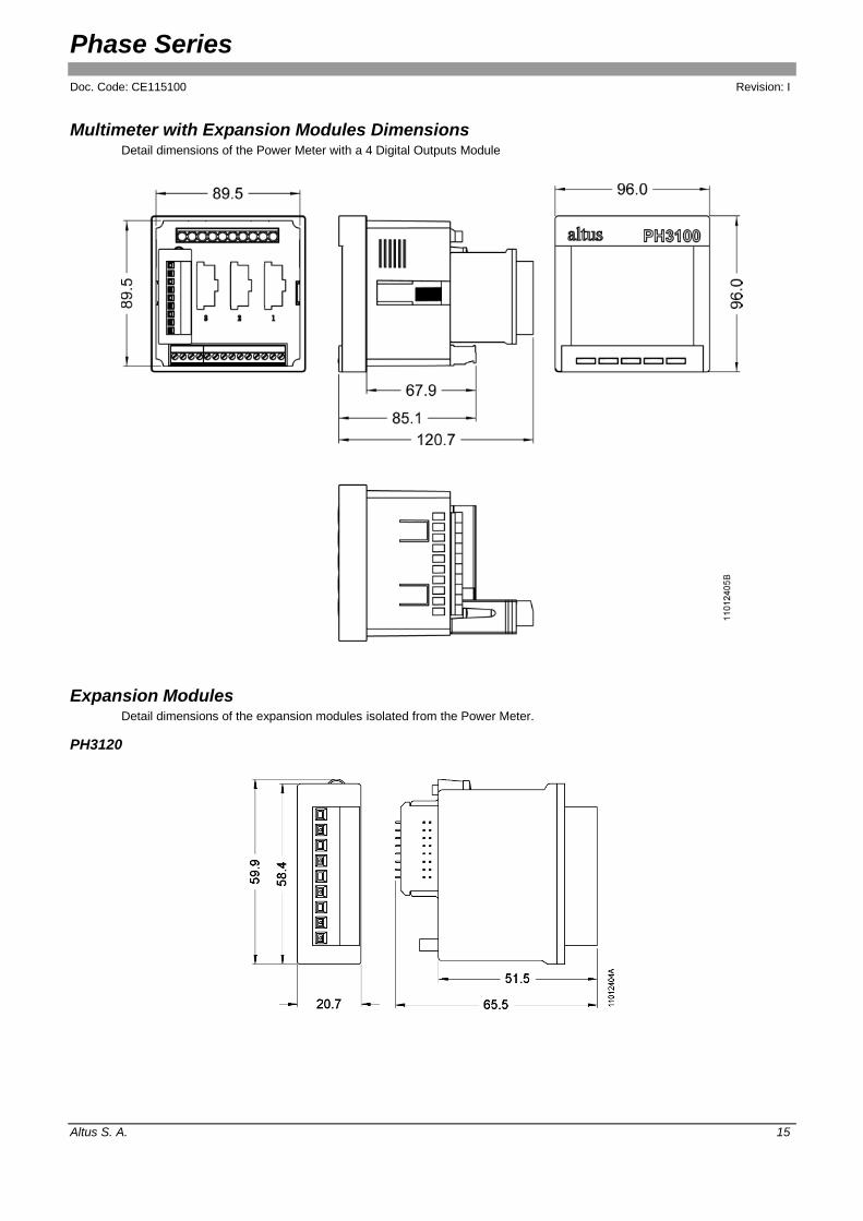
Multimeter with Expansion Modules Dimensions Detail dimensions of the Power Meter with a 4 Digital Outputs Module
Expansion Modules Detail dimensions of the expansion modules isolated from the Power Meter.
PH3120

Phase Series
Doc. Code: CE115100 Revision: I
Altus S. A. 16
PH3131
PH3150
PH3151

Phase Series
Doc. Code: CE115100 Revision: I
Altus S. A. 17
Manuals For more technical details, configuration, installation and programming of Phase series products, the following documents should be consulted:
Document code Description Language
CE115100 CT115100 CS115100
Phase Series – Technical Features Série Phase – Características Técnica Serie Phase – Especificación Técnica
English Portuguese Spanish
MU215300 MU215100 MU215500
Phase Series User Manual Manual de Utilização Série Phase Manual de Utilización Serie Phase
English Portuguese Spanish
Related Documents