1 23 !" #$!$ %& '($) ! "#$ !!

Welcome message from author
This document is posted to help you gain knowledge. Please leave a comment to let me know what you think about it! Share it to your friends and learn new things together.
Transcript
1 23
������ ������������ ���������� ��������������� ���������������������������������������������� !��"��#$!��$�%&���'�(��� �����$) ���
������� ����������������������������� ������������� ������������ ��� ������� ������ �!����������������������"#����$�� ��!!�����
������� �����������������������������

1 23
Your article is protected by copyrightand all rights are held exclusively by TheMinerals, Metals & Materials Society and ASMInternational. This e-offprint is for personaluse only and shall not be self-archived inelectronic repositories. If you wish to self-archive your article, please use the acceptedmanuscript version for posting on your ownwebsite. You may further deposit the acceptedmanuscript version in any repository,provided it is only made publicly available 12months after official publication or later andprovided acknowledgement is given to theoriginal source of publication and a link isinserted to the published article on Springer'swebsite. The link must be accompanied bythe following text: "The final publication isavailable at link.springer.com”.

Phase Field Simulation of Binary Alloy Dendrite Growth UnderThermal- and Forced-Flow Fields: An Implementationof the Parallel–Multigrid Approach
ZHIPENG GUO, J. MI, S. XIONG, and P.S. GRANT
Dendrite growth and morphology evolution during solidification have been studied using aphase field model incorporating melt convection e!ects, which was solved using a robust ande"cient parallel, multigrid computing approach. Single dendrite growth against the flow of themelt was studied under a wide range of growth parameters, including the Lewis number (Le)and the Prandtl number (Pr) that express the relative strengths of thermal di!usivity to solutedi!usivity and kinematic viscosity to thermal di!usivity. Multidendrite growths for bothcolumnar and equiaxed cases were investigated, and important physical aspects including soluterecirculation, tip splitting, and dendrite tilting against convection have been captured anddiscussed. The robustness of the parallel–multigrid approach enabled the simulation of dendritegrowth for metallic alloys with Le ~ 104 and Pr ~ 10!2, and the interplay between crystallo-graphic anisotropy and local solid/liquid interfacial conditions due to convection on thetendency for tip splitting was revealed.
DOI: 10.1007/s11663-013-9861-5! The Minerals, Metals & Materials Society and ASM International 2013
I. INTRODUCTION
THE commonly observed dendritic microstructureformed in metallic alloys following casting and solidi-fication is one of the main factors that determine themechanical properties of the final product.[1–6] Conse-quently, considerable e!ort has been expended in tryingto understand and control solidification conditions tomanipulate final microstructure. In practice, the use ofgrain refiners to promote nucleation and finer, moreequiaxed (as opposed to columnar) grains is verye!ective, while in the laboratory, considerable progresshas been made analytically and by simulation inunderstanding the columnar dendrite growth. Althoughthe growth of dendrites in real castings is alwaysaccompanied by convection of the melt,[7–10] whichmay be relatively quiescent or highly turbulent andprolonged, it is often ignored in analytic or theoreticaltreatment of dendrite growth to simplify these treat-ments. Fuller understanding of the coupled thermal–solutal–convective transport on dendrite growth mightallow us develop new strategies and casting designs thatcontrol better the final microstructure and properties.
Modeling and simulation are potentially powerfultools for investigating solidification phenomena. And bymaking use of increasingly powerful computing systems,
appropriate mathematical formulation of the interlinkedheat, momentum, and species conservation equationscan be achieved. The phase field method is becoming astandard tool for simulating dendritic microstructuralevolution because of its implementation advantages,including removing the need for complex, explicittracking of the solid–liquid interface.[11–13] Instead, inthe phase field approach, an extra equation (the phasefield equation) is introduced into the mathematicalformulation to characterize the transition between thesolid phase and the liquid phase through tracking thevariable /, termed the phase field, which is constant inbulk phases (!1 in liquid and 1 in solid) but changessteeply across the solid–liquid interface.Many studies have now been performed to simulate
the evolution of the dendritic microstructure by employ-ing the phase field method. One of the most influentialstudies was performed by Beckermann et al.[14] whodeveloped a phase field solidification model coupledwith convection by applying the so-called averagevolume technique. A pure material was considered,and therefore, there was no coupling of temperature andsolute fields. For a single dendrite, they showed that an‘‘upstream’’ primary arm grew faster than both the sideand the ‘‘downstream’’ primary arms. Similar phenom-ena were reported in Reference 15 which employed amultigrid approach to solve the Navier–Stokes equa-tions for the melt flow and where side-branching ofprimary dendrite arms was manifest as a ‘‘stretching’’ ofsecondary dendrite arms. The faster growth of upstreamprimary dendrite arms was suggested to be caused by anincrease of the e!ective undercooling at the dendritetip.[9,10,16–18]
E!orts have also been made to simulate alloy dendritegrowth during convection. Lan et al.[10,19] studied the
ZHIPENG GUO, Assistant Professor, and S. XIONG, Professor,are with the School of Materials Science and Engineering, TsinghuaUniversity, Beijing 100084, P.R. China. Contact e-mail: [email protected] J. MI, Lecturer, is with the Department ofEngineering, University of Hull, East Yorkshire HU6 7RX, UK. P.S.GRANT, Cookson Professor, is with the Department of Materials,University of Oxford, Parks Road, Oxford OX1 3PH, UK.
Manuscript submitted January 28, 2013.Article published online May 11, 2013.
924—VOLUME 44B, AUGUST 2013 METALLURGICAL AND MATERIALS TRANSACTIONS B
Author's personal copy

influence of convection on thermal–solute distributionsand morphologic changes in a freely growing dendrite.Siquieri and Emmerich[20] investigated the e!ect ofconvection on the morphology of an isothermal, freedendrite growth scenario, and again showed that anupstream dendrite arm grew fastest, but ignored anye!ects of the release of the latent heat. Despite theseadvances, the interplay between multiple dendrites andconvection in a coupled thermal and solute environmentfor a realistic metallurgical alloy has yet to be pro-gressed significantly.
The principal di"culties in simulating the coupledthermal–solutal–convective case are[21] (1) simulationsof multiple dendrite growth require a relatively largedomain, which in turn usually requires enormouscomputing e!ort, especially where the phase fieldmethod is adopted; and (2) the multiscale complexityof coupling temperature, solute, and convection fieldsthat operate over di!erent length and time scales.Despite the evergrowing power of computation, signif-icant progress can only be made for the fully coupledcase by developing new robust and e"cient numericalalgorithms and their implementation.
In the current article, a parallel–multigrid approach isused to solve the coupled phase field equations. Weshow that simulation of multiple dendrite growth in afully coupled thermal–solutal–convective arrangementcan be solved e"ciently and accurately. The simulationsreveal basic behavior of dendrite growth including side-branching, tip splitting, and various morphologic tran-sitions due—in particular—to convection. Di!erentaspects of solidification physics then become tractablefor simulation, including competing growth betweendendrites with di!erent orientations, self-adjusting spac-ing of dendrites due to temperature and solute trans-portation in the case of directional solidification (DS),and equiaxed dendrite tilting, and arm splitting due toexternal convection. Importantly, these simulations canbe performed at di!erent scales, including pushing theLewis number Le = a/D (ratio between thermal di!u-sivity and solute di!usivity) to ~104 and Prandtl numberPr = t/a (ratio between kinematic viscosity and ther-mal di!usivity) to ~10!2, which both approach those forrealistic metallic alloys in actual solidification conditionand which have generally not been studied before by lesse"cient and capable approaches.
II. THE PHASE FIELD MODELAND NUMERICAL APPROACH
To simplify the derivation of the phase field model,the following assumptions are made:
(1). All physical properties of materials are constantsunless stated otherwise. These properties includethermal di!usivity a, liquid solute di!usivity D,latent heat of melting L, alloy specific heat Cp,density q, and kinematic viscosity t.
(2). Solute di!usion in the solid phase is neglected.(3). Only forced convection is considered, i.e., the e!ect
of gravity force is neglected.
A. The Phase Field Model Coupled with Convection
By employing the Ginzburg–Landau free energyfunctional,[11,13]
F "Z
dVr2r/j j2#fAB /; c;T$ %
! "&1'
where F is the free energy of the system, and r is agradient energy coe"cient. fAB is a free energy densityfunction for a binary mixture of A and B and is a sumof the free energy of the pure material (double well)and the contribution due to solute addition, details ofwhich are found in Reference 13. /, c ,and T are phasefield, solute concentration, and temperature, respec-tively; according to References 13, 21 and References14, 15, the governing equations of the phase fieldmodel including convection are
s0@/@t" !K/
dFd/
&2'
@c
@t# mrc " r Kcr
dFdc! jat
# $&3'
@T
@t# mrT " ar2T# L
2Cp
@/@t
&4'
@m@t# mr m
fl
# $" !flrP# tr2m#Md
1 &5'
rm " 0 &6'
where s0 is the relaxation time, m is the ‘‘superficial’’velocity equivalent to the product of the local liquidfraction (fl = (1 ! /)/2) and the actual velocity. K/and Kc are constants. ja is the so-called anti-trappingcurrent developed by Karma and co-workers[11]
ja " !W0%%%2p c=c1
1# k! $1! k%/& '@/@t
r/r/j j
&7'
where W0 is the width of the di!use interface, k isthe partition coe"cient of solute, and c¥ is the initialsolute concentration in the liquid. The anti-trappingcurrent is used to counterbalance spurious e!ectsat the di!usion interface arising in phase field model-ing, details of which can be found in Reference 11.a is the thermal di!usivity, L is the latent heat offusion, Cp is the specific heat of alloy, P is pressure,and t is the kinematic viscosity. Md
1 is a dissipativeinterfacial force per unit volume as developed byBeckerman et al.:[14]
Md1 " !2thc 1! fl$ %2m &8'
where hc is 2.757 according to an asymptotic analysis ofa plane flow past the di!use interface. This term servesas a distributed momentum sink in the di!use interfaceregion, which forces the liquid velocity to zeroapproaching the solid and vanishes in the bulk liquid.
METALLURGICAL AND MATERIALS TRANSACTIONS B VOLUME 44B, AUGUST 2013—925
Author's personal copy

Applying the dimensionless forms of solute andtemperature
U "2c=c1
1#k!$1!k%/! 1
1! k&9'
h " T! TM !mc1L=Cp
&10'
and by scaling length and time to the interfacial widthW0 and relaxation time s0, the final governingequations are
A w$ %2 1
Le#Mc1 1# $1! k%U$ %
& '@/@t
" r A w$ %2r/! "
! @
@xA w$ %A w$ %0@/
@y
# $
# @
@yA w$ %A w$ %0@/
@x
# $# / 1! /2
( )
! k 1! /2( )2
h#Mc1U$ % 1# _n! "
&11'
1# k
2! 1! k
2/
# $@U
@t
" r ~D1! /2rU# 1
2%%%2p 1# 1! k$ %U& ' @/
@t
r/r/j j
# $
# 1
21# 1! k$ %U& ' @/
@t! 1
2~m*1# k! $1! k%/& 'rU
! 1# $1! k%U& 'r/+
&12'
@h@t" ~ar2h# 1
2
@/@t! ~mrh! _q &13'
@~m@t# ~mr
~mfl
# $" !flr ~P# ~tr2~m! 2~thc 1! fl$ %2~m &14'
r~m " 0 &15'
where k = 15L2/(16HCpTM) is a scaling parameterwith its reciprocal measuring the energy barrier heightH. TM is the melting temperature of the pure solvent.
Mc1 "mj j 1! k$ %c1
L=Cp&16'
is a scaled solute concentration factor where m is theactual liquidus slope of the phase diagram. The aniso-tropic e!ect can be characterized by function:
A w$ % " 1# e cos xw$ % &17'
where w is the angle between the interface norm nand the axis x, e weights the magnitude of the anisot-ropy strength, and x (4 or 6) is the symmetry or har-monic factor. To mimic the thermal fluctuations in thesystem, a single noise term _n was introduced inEq. [11] on the source term and realized using aGaussian distributed random number (mean = 0 and
variance = 1), i.e., GRN(0,1) with specific amplitudeNamp as
_n " Namp (GRN 0; 1$ %: &18'
In Eq. [13], _q is either a heat sink ( _q> 0) or heatsource ( _q< 0) to characterize the external cooling ormelting of the entire system. In Eqs. [11] through [15],variables with tilde are dimensionless.
B. The Orientation Field
In the case of multidendrite growth with randomlyoriented crystals, the orientation of the dendrite isanother important factor that needs to be taken intoaccount. Because the focus of the current study is on thedendrite growth and morphologic evolution underforced convection, a simpler approach for dendriteorientation is employed comprising two steps. First, theorientation of each of the dendrites is randomly specifiedwith a pre-existing solid seed introduced in the compu-tational domain. Second, as the dendrite grows, verysmall volumes of liquid are added/transformed to solid;the crystal orientation for this new increment in solid isassumed to be the same as that of the local crystalorientation of the dendrite. In other words, the dendritegrows by transformation of nearby liquid into solid ofthe same orientation, which is physically similar to thereal case and consistent with numerical approaches usedin these sharp interface methods.[22,23]
C. The Parallel–Multigrid Approach
Equations [11] through [15] were discretized using thefinite di!erence method onto a square computingdomain with equal grid spacing of Dx = Dy. Equations[11] through [13] were then solved by employing aparallel–multigrid approach, details which have beengiven elsewhere.[21] A staggered grid was employed forthe solution of the Navier–Stokes equations. Thestructure of an unit grid (or cell) is then composed ofphase field, temperature, and solute field occupying thefour corners, pressure at the center, and velocities atthe middle of each wall of the grid. Solving e"ciently theNavier–Stokes equation is not a trivial problem. In thecurrent study, asymmetric coupled Gauss–Seidel(SCGS) smoothing technique[24] was employed. Thisapproach was then parallelized by using a line smootherscheme.[25] According to the structure of the staggeredgrid, the parallelization of the SCGS scheme requiresthat during each relaxation step, at least two block (cell)lines of data be skipped, resulting in a three-step parallelblock line-smoothing scheme called the parallel-SCGS.
III. SINGLE DENDRITE GROWTH WITHCONVECTION
A. Description of the Computing Domain
Simulation was performed using a rectangulardomain of size #X = M 9 N where M and N are the
926—VOLUME 44B, AUGUST 2013 METALLURGICAL AND MATERIALS TRANSACTIONS B
Author's personal copy

numbers of cells in a row and a column, respectively.For the rectangular domain, the bottom left corner isregarded as the origin point, i.e., x = 0, and y = 0. Inthis respect, the left boundary will be located as x = 0,right boundary x = M, top boundary y = N and thebottom boundary y = 0. Convection of the liquid alloymelt was assumed from the top of domain flowingtoward the bottom. The boundary conditions were set asfollows. For the phase field, solute, and temperaturedistributions, all sides of the computing domain were setto a Neumann condition (gradient flux zero). Forconvection, the horizontal velocity u was set to be zeroat all boundaries; the vertical velocity at the top side ofthe domain was v = v0, while at the bottom side of thedomain ¶v/¶y = 0. For left and right sides, ¶v/¶x = 0.A no-slip boundary condition was applied at the solidsurface of the dendrite. The important calculationparameters used in the simulation were k = 0.15,crystallographic anisotropy strength e = 0.02 andMc¥ = 0.035, which corresponded to an Al-4 pct Cualloy as described in Reference 21. A relatively largescaling parameter, i.e., k = 15 was used in the calcula-tion to facilitate the growth of the dendrite whilekeeping the external undercooling Dh0 relatively smallto insure that W0vtip/D was smaller than the unity, asrequired for accurate phase field simulation. Dendritegrowth was initiated by placing a solid seed with radiusR0 = 30d0 (d0 is the thermal capillary length) at thecenter of the left side of the domain with temperatureh = 0, i.e., the nucleation step of solidification was notsimulated.
A fixed spatial step of Dx = 0.8 was used for allsimulations unless stated otherwise. The time step wasset as Dt = 0.8 9 Dx2/(4D), which was 0.8 9 Le timeslarger than the time step constrain for an explicitmethod. The accuracy and implementation consider-ations of selecting Dx and Dt and various othersimulation parameters were discussed in a previousstudy.[21] The computing domain had a relatively largesize of M = 4096 and N = 2048 to insure that therewas enough space for both temperature and flow todevelop fully around the dendrite as it grew.
B. The Use of Noise in Simulations
Side-branching of higher-order dendrite arms is oftenobserved in dendrite growth. To achieve this behavior inthe simulations, random numerical noise is usuallyapplied, perhaps mimicking the ‘‘natural’’ oscillationsand perturbations of the experimental environment.This noise can be introduced into all equations, includ-ing the phase field, temperature, and solute (if consid-ered) conservation equations.[4,26] However, thermalperturbation, i.e., noise in the temperature equation,has been suggested to provide the most significant e!ecton side-branching of higher-order arms; however, otherstudies indicate that this might not be always the case.[21]
In the current study as shown in Eq. [11], numericalrandom noise was only applied in the phase fieldequation on the source term, acting as an fluctuationof the driving force that consequently leads to thestretching and growth of the secondary dendrite arms.
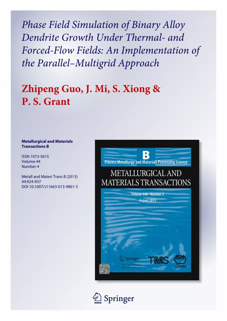
Figure 1 shows the calculated dendrite morphologyand solute iso-concentrates in the liquid at t = 3000Dt,for three di!erent noise amplitudes of Namp = 0, 10!6
and 10!3, a Lewis number Le = 100 and an externalimposed undercooling of Dh0 = 0.4. Without the appli-cation of noise, the dendrite was branchless, as shown inFigure 1(a). With the application of noise, side-branch-ing (as typically seen in experiment) developed. How-ever, as shown in Figures 1(b) and (c), the amplitude ofthe noise Namp had surprisingly little e!ect on thedetailed morphology of side-branching. Further numer-ical tests revealed that side branching occurred nomatter how small the value of Namp. This behavior wasquite di!erent from findings in literature, which sug-gested that the higher the magnitude of the noise thenthe more intense (size and frequency) the side-branch-ing. In the experiment, it is well known that exceptunder highly contrived conditions, there is always side-branching, and this is consistent with our numericalresults. The comparative sensitivity of other models tothe noise amplitude is not readily explained, but may beresolved by additional simulations under di!erent con-ditions, e.g., Lewis number, which lies outside the scopeof this article.Mathematically speaking, the implicit multigrid algo-
rithm employed here treats the noise as the residualerror in the various conservation equations and thesolving process for these equations will seek to eliminate(at least as fully as possible) such influence on the finalsolution. This is quite di!erent from the mechanismwhen an explicit algorithm is employed, which tends toaccumulate ‘‘error’’ induced by noise, ultimately ren-dering it on the calculated dendrite morphology. In thissense, there is a danger that explicit algorithms willsignificantly amplify the influence of noise on side-branching, beyond the sensitivity seen in practice.Nonetheless, the sensitivity of side-branching requiresfurther study to insure that such side branching arisesfrom correct formulation of the physics, rather thanfrom a coincidence of numerical error or instability.
C. Dendrite Morphology Changes During Convection
Using the same computing parameters applied inFigure 1 and with Pr = 0.23 and v0 = 30 W0/s0,Figures 2(a) and (b) show dendrite morphology andthe corresponding contour maps of solute and temper-ature without and with convection. The contour map ofthe solute concentration was flipped horizontally toachieve a better comparison with the contour map of thetemperature. The outline profiles at three di!erent timeswith an interval of 1000Dt are superimposed to show theevolution of the dendrite morphology in Figures 2(c)(without convection) and (d) (with convection), respec-tively. The corresponding changes of phase field (/),solute concentration (c/c¥) and temperature (h) alongthe line where x = 0 (as indicated in Figure 2(c)) at thethree time intervals are shown in Figures 2(e) and (f),respectively.Without convection and as expected, the dendrite
grew symmetrically with equal lengths of primary arms.Secondary arms stretched out and grew approximately
METALLURGICAL AND MATERIALS TRANSACTIONS B VOLUME 44B, AUGUST 2013—927
Author's personal copy
orthogonal to primary arms, although slightly tiltedtoward the primary arm’s growth direction, especiallythose near the dendrite center (seed) where interdendritespace became more crowded, the liquid fraction wascomparatively low and interdendritic solute concentra-tions were comparatively high. In these regions, and asseen in Figure 2(c), the dendrite released latent heat as itgrew, so that the temperature was comparatively highnearer the dendrite center. Taking the upper primaryarm for instance, because the temperature was relativelylow toward the tip, the secondary arms tended to growslightly tilted toward this region. As shown inFigure 2(e) without convection, the solute concentrationand temperature profiles around the upstream anddownstream primary arms were identical. Beyond theinitial transient when the seed first developed a dendriticmorphology, these profiles were essentially the same atall times, indicating that the dendrite grew in anapproximate steady state.
As convection was applied in Figures 2(b) and (d), thegrowth of the primary side arm was significantlyinhibited. As the melt flow propagated from top tobottom, solute rejected into the liquid during solidifica-tion was swept away from around the upstream dendritetip and carried (convected) downward, along the outsideprofile of the protruding secondary arms until the sidearm tip was reached, where the flow then swept aroundthe side arm tip into the downstream region. Solute thenaccumulated at the side arm tip, as indicated inFigure 2(d) by the arrowed number ‘‘1’’. According tothe phase diagram, a higher solute concentration leadsto a lower solidification liquidus temperature so that the
solute pile-up inhibits the growth of the side arm relativeto the upstream side which was comparatively depletedof solute. Faster dendrite growth on the upstream sidehas been reported in the literature for a pure materialdendrite,[14–18] but the presence of solute build up in analloy, which di!uses much slower than heat, exacer-bates this upstream–downstream di!erence. From Fig-ures 2(e) and (f), the temperature at the upstream armtip was h = !0.16, which was slightly lower than that atthe downstream primary arm tip of h = !0.156, andboth these temperatures were higher than when convec-tion was absent and h = !0.168. Although a highertemperature should tend to decelerate the growth of theupstream primary arm, it is the solute e!ect that isdominant and leads to the faster growth. FromFigures 2(e) and (f), the solute concentration at theupstream primary arm tip was ~1.95c¥, lower than thatat the downstream primary arm tip of ~2.06c¥, andsignificantly lower than without convection of ~2.15c¥.As in the case of the upstream primary arm, the
growth of the secondary arms in the upstream regionwas also strongly promoted while growth of secondaryarms on the downstream side was inhibited by soluterecirculation eddies, as shown in Figure 2(d).Overall, Figure 2 shows how dendrite growth was
influenced by the interplay between solute and temper-ature distribution, and the e!ect of convection. ForLe = 100 and Pr = 0.23, solute gradients and locallydepleted or concentration regions in the liquid weremore pronounced than variations in temperature: heatflowed relatively fast with respect to convection/di!u-sion under these conditions.
Fig. 1—Comparison of dendrite morphology at t = 3000Dt with di!erent noise amplitude (a) Namp = 0, (b) Namp = 10!6, and(c) Namp = 10!3. The noise is a product of a Gaussian distributed random number with mean of zero and standard deviation of unity and Namp.
928—VOLUME 44B, AUGUST 2013 METALLURGICAL AND MATERIALS TRANSACTIONS B
Author's personal copy

D. Influence of Dendrite Growth Parameters
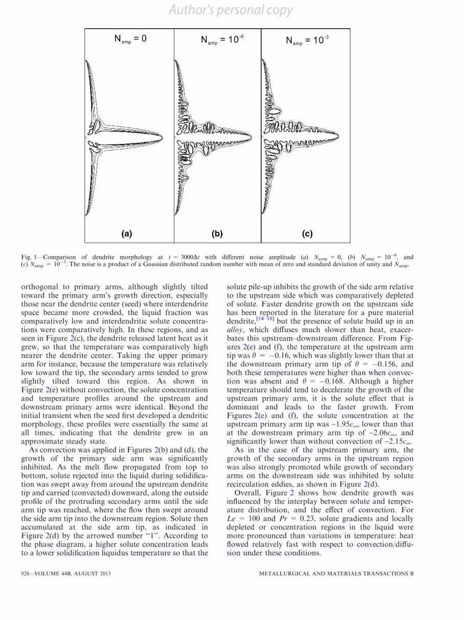
Figures 3(a) through (g) again show a series ofdendrite morphologies and contour line maps of soluteconcentration (left) and temperature (right) for di!erentcombinations of the four major parameters related todendrite growth: inlet flow velocity v0, Prandtl numberPr, anisotropic strength e, and Lewis number Le. Onlyone parameter was varied in each figure, and dendriteswere allowed to grow to reach similar sizes (longersimulation times were required for a lower level ofanisotropy).
Figures 3(a) through (c) show that an increase of theinlet velocity (from 0 to 10 and then 30 with units ofW0/s0) promoted strongly the growth of the upstreamprimary arm while decelerating the growth of the sideprimary arm, as previously explained. However, thelength of the downstream primary arm was slightlyshorter at v0 = 10 than at v0 = 30, as shown bycomparing Figures 3(b) and (c). The particular waythe downstream solute eddy recirculated was responsible
for these di!erences. As seen in Figure 3(c), when theflow velocity was comparatively high at v0 = 30, theeddy pattern occupied more area than that when flowvelocity was at v0 = 10 lower (Figure 3(b)), and theflow direction of the eddy at v0 = 30 circulating againstthe lower primary dendrite arm was upstream, whereasat v0 = 10, the eddy flow against the dendrite tip wasdownstream. The net e!ect was that the solute sweptfrom the upper regions of the dendrite and recirculating‘‘behind’’ the side arms was dispersed over a greatereddy area in Figure 3(c) than in Figure 3(b) so that thesolute concentration at the downstream primary armwas comparatively low for v0 = 30, undercooling theliquid relative to the v0 = 10 case, and encouragingdendrite growth.The increase of the Prandtl number from Pr = 0.23
to 23 in Figure 3(d) reversed this behavior with recir-culation against the downstream dendrite arm tip nowprimarily downstream, and the primary side arm alsobecame significantly longer. This can be understood by
Fig. 2—Contour maps of solute and temperature of dendrite (a) without and (b) with convection. The outlines of the dendrite corresponding to/ = 0 at three di!erent times are superimposed and shown in (c) without and (d) with convection. Accordingly, the change of phase field, solutetransition, and temperature along the line where x = 0 as indicated in (c) are shown in (e) without and (f) with convection, respectively.Distance from seed center in (e) and (f) will be positive on the upstream side while negative on the downstream side.
METALLURGICAL AND MATERIALS TRANSACTIONS B VOLUME 44B, AUGUST 2013—929
Author's personal copy
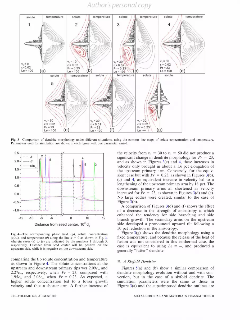
comparing the tip solute concentration and temperatureas shown in Figure 4. The solute concentrations at theupstream and downstream primary tips wer 2.09c¥ and2.27c¥, respectively, when Pr = 23, compared with1.95c¥ and 2.06c¥ when Pr = 0.23. As expected, ahigher solute concentration led to a lower growthvelocity and thus a shorter arm. A further increase of
the velocity from v0 = 30 to v0 = 50 did not produce asignificant change in dendrite morphology for Pr = 23,and as shown in Figures 3(e) and 4, these increases invelocity only brought in about a 1.6 pct elongation ofthe upstream primary arm. Conversely, for the equiv-alent case but with Pr = 0.23, as shown in Figures 3(b),(c) and 4, an equivalent increase in velocity led to alengthening of the upstream primary arm by 18 pct. Thedownstream primary arms all shortened as velocityincreased for Pr = 23, as shown in Figures 3(d) and (e).No large eddies were created, similar to the case ofFigure 3(b).A comparison of Figures 3(d) and (f) shows the e!ect
of a decrease in the strength of anisotropy e, whichenhanced the tendency for side branching and sidebranch growth. The secondary arms on the upstreamside developed a pronounced upward tilt following a50 pct reduction in the anisotropy.Figure 3(g) shows the dendrite morphology using a
fixed temperature, and because the release of the heat offusion was not considered in this isothermal case, thecase is equivalent to using Le = ¥, and produced agenerally ‘‘fatter’’ dendrite.
E. A Sixfold Dendrite
Figures 5(a) and (b) show a similar comparison ofdendrite morphology evolution without and with con-vection, but in the case of a sixfold dendrite. Thesimulation parameters were the same as those inFigure 3(a) and the superimposed dendrite outlines are
Fig. 3—Comparison of dendrite morphology under di!erent situations, using the contour line maps of solute concentration and temperature.Parameters used for simulation are shown in each figure with one parameter varied.
Fig. 4—The corresponding phase field (/), solute concentration(c/c¥), and temperature (h) along the line x = 0 as shown in Fig. 3,wherein cases (a) to (e) are indicated by the numbers 1 through 5,respectively. Distance from seed center will be positive on theupstream side, while it is negative on the downstream side.
930—VOLUME 44B, AUGUST 2013 METALLURGICAL AND MATERIALS TRANSACTIONS B
Author's personal copy

at time intervals of 1000Dt. The insert figure ofFigure 5(b) shows the flow streamlines. In contrast tothe fourfold dendrites, the secondary dendrite armswithout convection did not grow approximately normalto the primary dendrite trunk. Taking the upper primaryarm for instance, nearly all the secondary arms weretilted at ~30 deg to the normal. The primary armsgrowing along the y axis were slightly longer (~8 pct)than the other primary arms (shown by the circlestouching the dendrite tips in Figures 5(a) and (b)) andindicated that ‘‘grid anisotropy’’ was introduced duringthe simulations. Numerical tests subsequently showedthat this artificial anisotropy could be significantlyreduced by decreasing the size of the grid, i.e., a halvingof Dx = Dy reduced the di!erence in length by 80 pct.
The presence of convection in Figure 5(b) againenhanced the growth of the upstream primary arm,and side-branch growth was promoted strongly on bothsides of the upstream dendrite, and on the upstream sideof primary side arms. The downstream primary arm didnot change the length appreciably but the primary sidearms, and all downstream side arms were much reducedbecause of the trapping of solute in the eddies shown inthe insert of Figure 5(b).
Figures 3 and 5 show that convection-enhancedupstream primary arm growth and eddy behaviorstrongly influenced downstream growth. The strengthof the convection in terms of a recirculating eddy islargely determined by the Prandtl number Pr and whenPr< 1, the recirculation behavior will be pronounced.In this case, solute is distributed, or dispersed, over arelatively large eddy and e!ects on growth in thedownstream region are relatively weak. When Pr> 1,eddies tend to be smaller, any solute swept fromupstream regions is comparatively concentrated intothese eddies and the growth of the downstream primaryor secondary dendrite arm is inhibited. Similar concen-tration e!ects develop if the eddies are constrained by
geometry, such as in the downstream region of thesixfold dendrite, so that again the solute concentrationper unit area (or per unit volume in 3D) is relativelyconcentrated. When Pr< 1, the convection patternshave greater influence on growth than temperature, andthe scenario becomes similar to that of dendritic growthof a pure material.
IV. MULTIDENDRITE GROWTH
A. Domain Description and Computing Considerations
Two situations are considered concerning multiden-drite growth with convection. In the first case, the flowwas introduced along the top of the domain at aconstant velocity from left to right (an x velocitycomponent only), which induced a recirculating flowinside the computational domain. No slip boundarycondition was applied for the domain sides, other thanthe top. The second case was similar to that applied forthe single dendrite in Section III, i.e., the liquid meltflowed through the domain from top to bottom,entering with a constant velocity in the y direction only.To insure that all dendrites were fully developed, a
relatively large domain size of #X = 8192 9 8192 wasused. For the first case, 15 dendrites were seeded withrandom orientation at the bottom of the domain whilefor the second case, 9 dendrites were seeded randomly inthe domain. The magnitude of the applied velocity forboth cases was fixed at v0 = 30 W0/s0. For the calcu-lation, 192 cores were used (16 nodes and 12 cores), withmost simulations being completed in less than 10 hours.The first case approximated to that of DS, commonly
applied in both experiment and industry. However, inexperiment, a finite temperature gradient is imposedfrom top to bottom, whereas here the top and bottom ofthe computational domain were maintained at the same
Fig. 5—Comparison of sixfold dendrite morphology: (a) without and (b) with convection. The outlines of the dendrite corresponding to / = 0at di!erent time scales at intervals of 1000Dt are superimposed.
METALLURGICAL AND MATERIALS TRANSACTIONS B VOLUME 44B, AUGUST 2013—931
Author's personal copy
constant undercooling temperature, i.e., zero tempera-ture gradient. Because no nucleation events were sim-ulated and the seeds were constrained to remain at thebottom of the domain, their subsequent growth quali-tatively mimicked the microstructures developed duringDS. While it is possible to impose a finite gradient in thesimulations, this was not pursued for the followingreason, common to all current phase field approaches.Although the applied domain size M = N = 8192 wasrelatively large for this type of simulation, the physicaldomain size recovered by transforming the nondimen-sional units used in calculation to real lengths was~100 9 100 lm for the case of a metallic alloy such asAl-Cu, or ~500 9 500 lm for an organic/transparentalloy. In such a ‘‘small’’ domain, the applied tempera-ture gradient for typical DS conditions would benegligible. For example, for an Al-Cu alloy and assum-ing the temperature gradient as ~100 K/mm, the tem-perature di!erence (between the top and bottom sides ofdomain) would be Dh ~ 0.0275, which yielded nosignificant di!erence in simulation results of microstruc-ture to that produced in the isothermal case. Nonethe-less, this observation highlights the restriction of mostphase field simulations of dendrite growth, which is notalways appreciated, and that the real time and lengthscales are usually far from realistic, while the robustnessand e"ciency of the current model begins to allow morerealistic solidification conditions to be explored.
Furthermore, it is worth highlighting that the simu-lations for both columnar and equiaxed cases are quitedi!erent from phase field simulations in the literaturewhere the release of latent heat is usually ignored. Thegrowth of dendrites in the current study, including key
characteristics such as the tip velocity, morphologyevolution and adjustment of the primary and secondaryarm spacing are determined by the full coupling ofthermo-solutal fields for the first time. The focus of themultiple dendrite growth simulations is the interplay ofmultidendrites on the growth transients and any e!ectsof the forced convection on morphology change. Den-drite growth under somewhat extreme conditions, i.e.,against a large magnitude flows, is also discussed.
B. Columnar Dendrite Growth with Convection
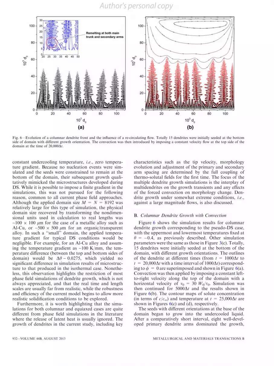
Figure 6 shows the simulation results for columnardendrite growth corresponding to the pseudo-DS case,with the uppermost and lowermost temperatures fixed ath = !0.4, as previously described. Other simulationparameters were the same as those in Figure 3(c). Totally,15 dendrites were initially seeded at the bottom of thedomain, with di!erent growth orientations. The outlinesof the dendrite at di!erent times (from t = 1000Dt tot = 20,000Dtwith a time interval of 1000Dt) correspond-ing to/ = 0are superimposed and shown in Figure 6(a).Convection was then applied by imposing a constant left-to-right velocity along the top of the domain with ahorizontal velocity of v0 = 30 W0/s0. Simulation wasthen continued for 5000Dt and the results shown inFigure 6(b). The contour maps of solute concentration(in terms of c/c¥) and temperature at t = 25,000Dt areshown in Figures 6(c) and (d), respectively.The seeds with di!erent orientations at the base of the
domain began to grow into the undercooled liquid.After a comparatively short interval, eight well-devel-oped primary dendrite arms dominated the growth,
Fig. 6—Evolution of a columnar dendrite front and the influence of a re-circulating flow. Totally 15 dendrites were initially seeded at the bottomside of domain with di!erent growth orientation. The convection was then introduced by imposing a constant velocity flow at the top side of thedomain at the time of 20,000Dt.
932—VOLUME 44B, AUGUST 2013 METALLURGICAL AND MATERIALS TRANSACTIONS B
Author's personal copy

reaching approximately similar lengths after 20,000Dt.These were the fastest growing primary arms, mostfavorably oriented and spaced. As seen fromFigure 6(a), as a direct result of growth competition,these ‘‘selected’’ dendrites mostly grew with the primarydendrite arm parallel to the y axis, i.e., the fastestgrowing direction. The behavior is in qualitative agree-ment with solidification theory and experimental resultsobtained by imaging of organic alloy analogs at roomtemperature and metallurgical alloys using synchrotronX-ray imaging.[27,28]
As seen from the inset figure of Figure 6(a), as thedendrite grows, secondary arms can remelt at their rootsand detach from the primary trunk. If buoyancy forceswere included in the simulation, then it can be conjec-tured that for the binary Al-Cu alloy, where the solidhas lower density than the liquid, these detachedsecondary arms would move upward into the unsolid-ified melt. This behavior is known to lead to ‘‘freckling’’in Ni superalloys produced by DS, and can also bereadily observed in synchrotron X-ray imaging experi-ments, which leads to a columnar-to-equiaxed transition.[28]
Fig. 7—Superimposed dendrite outlines at / = 0 under the case of Le = 100 and Pr = 0.23 showing the comparison of equiaxed multidendritegrowth (a) without and (b) with forced convection (v0 = 30) applied from top to bottom of the domain. The corresponding contour maps ofsolute concentration and temperature at 7000Dt for (b) are shown in (c) and (d), respectively.
METALLURGICAL AND MATERIALS TRANSACTIONS B VOLUME 44B, AUGUST 2013—933
Author's personal copy
The remelting at the base of secondary dendrite armsarose from local solute enrichment in the interdendriticregion as growth proceeded, latent heat was evolved,and the comparatively sharp local curvature of thesolid–liquid interface that increased its relative solubil-ity. To the best knowledge of the authors, this is the firsttime these features are revealed in such detail by phasefield simulations, which can only be achieved if therelease of the latent heat is considered.
The introduction of convection in Figure 6(b) did nothave a strong influence on dendrite growth comparedwith its generally pronounced e!ect on equiaxed den-drite growth. Although, ahead of the primary dendritetips, the induced recirculation was comparatively strong,the perpendicular velocity across the dendrite front wasclose to zero. For this particular combination of flowcondition and thermophysical parameters, the spacingof the dendrites was too close for interdendritic flow to
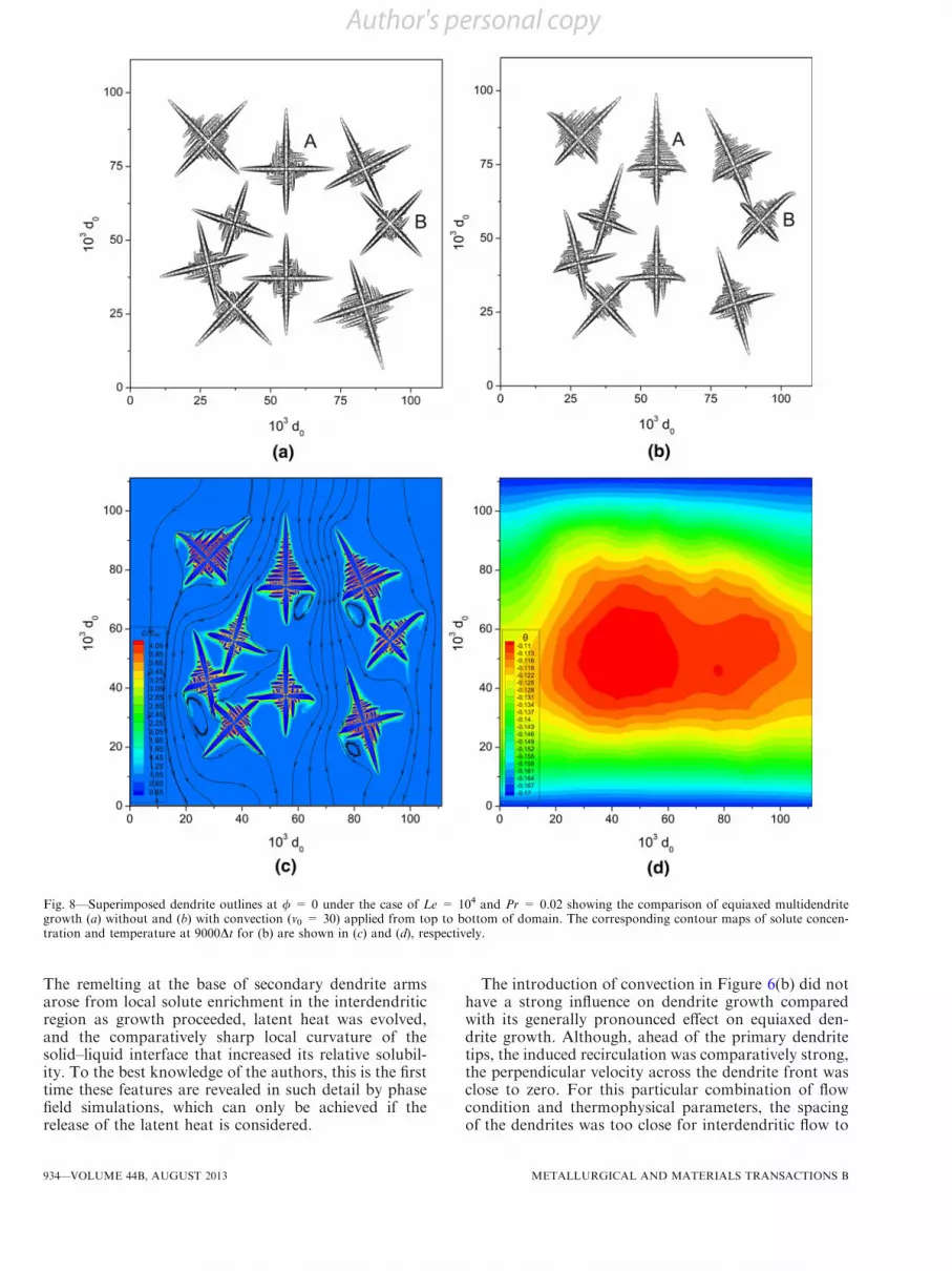
Fig. 8—Superimposed dendrite outlines at / = 0 under the case of Le = 104 and Pr = 0.02 showing the comparison of equiaxed multidendritegrowth (a) without and (b) with convection (v0 = 30) applied from top to bottom of domain. The corresponding contour maps of solute concen-tration and temperature at 9000Dt for (b) are shown in (c) and (d), respectively.
934—VOLUME 44B, AUGUST 2013 METALLURGICAL AND MATERIALS TRANSACTIONS B
Author's personal copy

be induced, and the solute distribution (Figure 6(c)) andtemperature (Figure 6(d)) in these regions were largelyinsensitive to bulk movement of the liquid ahead of thefront.
C. Equiaxed Dendrite Growth with Convection
Figure 7 shows similar results to Figure 6 (with samesimulation parameters) but for the case of equiaxeddendrites. Figure 7(a) is without convection while
Figure 7(b) includes convection under the same condi-tions as those considered in Figure 3(c). The outlineprofiles for / = 0 from 1000Dt to 8000Dt (with intervalsof 1000Dt) are superimposed and shown in Figures 7(a)and (b), while the contour maps of solute concentrationand temperature at 7000Dt of Figure 7(b) are shown inFigures 7(c) and (d), respectively.The presence of the convection changed the morphol-
ogy of all the dendrites with a promotion of growth inthe upstream direction, most notably for secondary
Fig. 9—Splitting and tilting of an equiaxed dendrite, extracted from Figs. 7 and 8 with (a) Le = 104, no convection applied, (b) Le = 102, noconvection applied, (c) Le = 102, v0 = 30, Pr = 23 and (d) Le = 102, v0 = 30 and Pr = 0.
METALLURGICAL AND MATERIALS TRANSACTIONS B VOLUME 44B, AUGUST 2013—935
Author's personal copy
dendrite arms; correspondingly, the growth of the sideand downstream primary arms was significantly inhib-ited. In the early stages, there was little interaction ofdendrites in terms of their surrounding solute, temper-ature or local flow fields. However, as more solid wasdeveloped, the gaps between dendrites reduced and theflow pattern changed: local velocities through narrowinggaps increased with a commensurate increase in recir-culation beyond the constrictions. For example, adja-cent to some of the dendrites, the local liquid velocityincreased five times over the period of the calculation asliquid flowed through the progressively narrowing gapbetween dendrites.
Figure 7(b) shows further intriguing behavior. Thedendrite on the extreme right of the domain labeled ‘‘B’’was initialized so that primary arms were 45 deg to thetop to bottom flow direction. As it grew, the primarydendrite arm first split and then continued to grow,gradually tilting toward the incoming flow. Othersimulations emphasized that convection tended toencourage tip splitting, resulting in unusual dendritemorphologies. Further discussion is given in the nextsection.
Unlike the columnar case, there was no remelting ofprimary arms in Figure 7(a) under broadly simulationconditions, even though the local solute concentration inbetween the dendrite arms, either primary or secondary,was more or less the same (as specified by the phasediagram). The way in which the temperature evolvedaround the di!erent dendrite morphologies may play arole.
Figure 8 shows similar calculations to those presentedin Figure 7 but for Le = 104. To achieve similar growthvelocities to those in Figure 7 a lower temperature ofh = !0.17 was employed at both the top and bottomsides of domain because otherwise the faster heattransfer associated with a larger Lewis number wouldproduce a much larger e!ective undercooling. Theoutline profiles for / = 0 from 1000Dt to 9000Dt (withintervals of 1000Dt) are superimposed and shown inFigures 8(a) and (b) and the corresponding contourmaps of solute concentration and temperature at 9000Dtfor Figure 8(b) are shown in Figures 8(c) and (d),respectively. Further, Pr = 0.023 which was approxi-mately that of an Al-Cu alloy was assumed. This morerealistic combination of Le and Pr highlighted multi-scale aspects that are usually problematic for these typesof calculation: thermal transport is much faster thansolute and fluid transport, and depending on flowconditions, there is a similar mismatch between soluteand fluid (convection) length-scales. Nevertheless, thecurrent multigrid algorithm worked perfectly well underthese traditionally ‘‘extreme’’ conditions, and the simu-lation time was more or less the same as for theconventional, generally considered more tractableconditions of Figure 7.
When Le increased from 102 to 104, the temperaturedistribution shown in Figure 8(d) became much moreuniform. Consequently, the dendrite morphology wasalso di!erent with much less side-branching, althoughagain there was marked di!erence in upstream anddownstream behaviors. Figure 8(c) shows that under
these conditions, the solute distributions around den-drites extended over shorter distances. For example, thesolute ‘‘tail’’ under the tip of the side primary arm ofdendrite ‘‘A’’ was significantly reduced when the Lewisnumber was increased.Returning to Figure 8(a), the tip splitting of dendrite
‘‘B’’ previously described for Figure 7(a) no longeroccurred when Le = 104. To consider this behaviorfurther, the morphology of dendrite ‘‘B’’ under di!erentconditions is shown in more detail in Figure 9. WithLe = 104 in Figure 9(a), there was no tip splitting,whereas with Le = 102 in Figure 9(b), the splittingoccurred very early in the growth for all primarydendrites, but only for this dendrite orientation. Atlow Lewis number, heat transport was comparativelyslow, and therefore the implication was that, under theseconditions, there was a sensitive interplay between thecrystal anisotropy and the local temperature gradients.When the Lewis number is increased toward those ofmetallic alloys, heat flowed faster, local temperaturesbecame more isotropic, and there was no driving forceto split the tip; indeed, no tip splitting was contrived forany combination of parameters, flow conditions, ordendrite orientation in the simulations when Le = 104.However, when Le = 102 in Figures 9(c) and (d),convection did have a strong influence on tip behavior.In Figure 9(c), all dendrite arms had a single split, whileone arm on the upstream right-hand side underwentmultiple tip splittings and gave a morphology similar tothe growth structure developed when a dendrite growsalong the [111] crystal plane.[29] The inference thereforeis that convection had an influence on the local solid–liquid interfacial conditions analogous to the e!ect tocrystallographic anisotropy: under strong convection,the controlling e!ect of crystallographic anisotropy ongrowth morphology was weakened, which in turn led tomultiple tip splittings as the dendrite sought to accom-modate local thermodynamic conditions dominated byflow e!ects. Figure 9(d) shows how this e!ect can beexacerbated further by increasing the e!ective convec-tion strength via a decrease in the Prandtl number from23 to 0.23, with extensive tip splitting and arm tiltingtoward the incoming flow. This change of the localgrowth conditions could be termed ‘‘convection-inducedanisotropy,’’ and can dominate over inherent crystalanisotropy under certain conditions.
V. CONCLUSIONS
Dendrite growth against forced convection in acoupled thermosolutal situation has been studied usingsimulations based on the phase field method. Thevarious coupled equations have been solved by employ-ing an e"cient parallel, multigrid numerical approach.Dendrite side branching or stretching of secondary armswas achieved by introducing random noise to thesimulations, where the noise magnitude was responsibleonly for the initiation of side branching with nosubsequent e!ect on growth morphology. Dendritemorphology evolution under di!erent combinations ofgrowth-related parameters including the magnitude of
936—VOLUME 44B, AUGUST 2013 METALLURGICAL AND MATERIALS TRANSACTIONS B
Author's personal copy
flow velocity, Prandtl number, Lewis number, and thecrystallographic anisotropy strength has been studied.Under predominantly one-dimensional flow, convectionof the melt enhanced the growth of upstream primaryarms and inhibited the growth of both side anddownstream primary arms. The flow-related solute andtemperature distributions controlled upstream–down-stream growth di!erences, the relative strengths ofwhich were determined by the magnitude of the Lewisand Prandtl number. The role of solute-rich recirculat-ing eddies has been simulated in detail, and thesensitivity in particular to the Prandtl number revealed.
Multidendrite growth under convection was alsostudied for both columnar and equiaxed dendritegrowth. Primary and secondary arm dendrite remeltingwas predicted in later stages of solidification as inter-dendritic solute concentrations increased. Under realis-tic metallic alloy conditions of Le ~ 104 and Pr ~ 0.023corresponding to an Al-Cu alloy, multidendrite growthboth with and without convection was successfullysimulated in sensible times, emphasizing the robustnessof the algorithm and numerical approach. By exploitingthis stability, the detailed influence of flow on growthwas studied, and the promotion of tip splitting anddendrite tilting was rationalized by the progressivesuppression of crystallographic anisotropy e!ects bylocal flow-induced conditions that forced significantlocal departures from equilibrium. These e!ects weremost predominantly manifest when thermal conductiv-ity was comparatively low; otherwise, the comparativelyfaster transport of heat was the dominant factor inmicrostructural evolution.
ACKNOWLEDGMENTS
The authors would like to thank the Natural ScienceFoundation of China (Project No. 51205229), theU.K. Royal Academy of Engineering/Royal Societythrough Newton International Fellowship Scheme, andthe EPSRC Centre for Innovative Manufacture:Liquid Metal Engineering (EP/H026177/1) for finan-cial support, and the Oxford Supercomputer Centre,and the National Laboratory for Information Scienceand Technology in Tsinghua University for grantingaccess to the supercomputing facilities and support forthe parallel programming.
REFERENCES1. M. Asta, C. Beckermann, A. Karma, W. Kurz, R. Napolitano, M.
Plapp, G. Purdy, M. Rappaz, and R. Trivedi: Acta Mater., 2009,vol. 57, pp. 941–71.
2. W.J. Boettinger, J.A. Warren, C. Beckermann, and A. Karma:Annu. Rev. Mater. Res., 2002, vol. 32, pp. 163–94.
3. L.-Q. Chen: Annu. Rev. Mater. Res., 2002, vol. 32, pp. 113–40.4. L. Granasy, T. Pusztai, and J.A. Warren: J. Phys.: Condens.
Matter, 2004, vol. 16, pp. R1205–R1235.5. T. Haxhimali, A. Karma, F. Gonzales, and M. Rappaz: Nat.
Mater., 2006, vol. 5, pp. 660–64.6. N. Moelans, B. Blanpain, and P. Wollants: CALPHAD, 2008,
vol. 32, pp. 268–94.7. A. Badillo, D. Ceynar, and C. Beckermann: J. Cryst. Growth,
2007, vol. 309, pp. 216–24.8. C. Giummarra, J.C. LaCombe, M.B. Koss, J.E. Frei, A.O.
Lupulescu, and M.E. Glicksman: J. Cryst. Growth, 2005, vol. 274,pp. 317–30.
9. C.W. Lan, C.M. Hsu, and C.C. Liu: J. Cryst. Growth, 2002,vol. 241, pp. 379–86.
10. C.W. Lan and C.J. Shih: J. Cryst. Growth, 2004, vol. 264, pp. 472–82.
11. A. Karma: Phys. Rev. Lett., 2001, vol. 87, p. 115701.12. J.C. Ramirez and C. Beckermann: Acta Mater., 2005, vol. 53,
pp. 1721–36.13. J.C. Ramirez, C. Beckermann, A. Karma, and H.J. Diepers: Phys.
Rev. E, 2004, vol. 69, p. 051607.14. C. Beckermann, H.J. Diepers, I. Steinbach, A. Karma, and X.
Tong: J. Comput. Phys., 1999, vol. 154, pp. 468–96.15. X. Tong, C. Beckermann, A. Karma, and Q. Li: Phys. Rev. E,
2001, vol. 63, p. 061601.16. D.M. Anderson, G.B. McFadden, and A.A. Wheeler: Physica D,
2000, vol. 135, pp. 175–94.17. D.M. Anderson, G.B. McFadden, and A.A. Wheeler: Physica D,
2001, vol. 151, pp. 305–31.18. R. Tonhardt and G. Amberg: J. Cryst. Growth, 2000, vol. 213,
pp. 161–87.19. C.W. Lan, C.J. Shih, and M.H. Lee: Acta Mater., 2005, vol. 53,
pp. 2285–94.20. R. Siquieri and H. Emmerich: Philos. Mag., 2011, vol. 91, pp. 45–
73.21. Z. Guo, J. Mi, and P.S. Grant: J. Comput. Phys., 2012, vol. 231,
pp. 1781–96.22. L. Beltran-Sanchez and D. Stefanescu: Metall. Mater. Trans. A,
2004, vol. 35A, pp. 2471–85.23. M.F. Zhu and D.M. Stefanescu: Acta Mater., 2007, vol. 55,
pp. 1741–55.24. S.P. Vanka: J. Comput. Phys., 1986, vol. 65, pp. 138–58.25. U. Trottenberg, C. Oosterlee, and A. Schuller: Multigrid,
Academic Press, London, U.K., 2001.26. A. Karma and W.-J. Rappel: Phys. Rev. E, 1999, vol. 60, pp. 3614–
25.27. L. Arnberg and R. Mathiesen: JOM, 2007, vol. 59, pp. 20–26.28. D. Ruvalcaba, R.H. Mathiesen, D.G. Eskin, L. Arnberg, and L.
Katgerman: Acta Mater., 2007, vol. 55, pp. 4287–92.29. B. Utter, R. Ragnarsson, and E. Bodenschatz: Phys. Rev. Lett.,
2001, vol. 86, pp. 4604–07.
METALLURGICAL AND MATERIALS TRANSACTIONS B VOLUME 44B, AUGUST 2013—937
Author's personal copy
Related Documents