Phase control of squeezed vacuum states of light in gravitational wave detectors K. L. Dooley, 1,2, * E. Schreiber, 1 H. Vahlbruch, 1 C. Affeldt, 1 J. R. Leong, 1 H. Wittel, 1 and H. Grote 1 1 Max-Planck-Institut f¨ ur Gravitationsphysik (Albert Einstein Institut) and Leibniz Universit¨ at Hannover, Callinstr.38, 30167 Hannover, Germany 2 Current address: The University of Mississippi, University, Mississippi 38677, USA * [email protected] Abstract: Quantum noise will be the dominant noise source for the advanced laser interferometric gravitational wave detectors currently under construction. Squeezing-enhanced laser interferometers have been recently demonstrated as a viable technique to reduce quantum noise. We propose two new methods of generating an error signal for matching the longitu- dinal phase of squeezed vacuum states of light to the phase of the laser interferometer output field. Both provide a superior signal to the one used in previous demonstrations of squeezing applied to a gravitational-wave detector. We demonstrate that the new signals are less sensitive to misalign- ments and higher order modes, and result in an improved stability of the squeezing level. The new signals also offer the potential of reducing the overall rms phase noise and optical losses, each of which would contribute to achieving a higher level of squeezing. The new error signals are a pivotal development towards realizing the goal of 6 dB and more of squeezing in advanced detectors and beyond. © 2015 Optical Society of America OCIS codes: (270.6570) Squeezed states; (120.3180) Interferometry; (120.5050) Phase measurement; (000:2190) Experimental physics. References and links 1. G. M. Harry and the LIGO Scientific Collaboration, “Advanced LIGO: the next generation of gravitational wave detectors,” Class. Quant. Grav. 27, 084006 (2010). 2. K. Somiya, “Detector configuration of KAGRA–the Japanese cryogenic gravitational-wave detector,” Class. Quant. Grav. 29, 124007 (2012). 3. The Virgo Collaboration, “Advanced Virgo baseline design,” Tech. Rep. VIR-027A-09 (2009). 4. C. M. Caves, “Quantum-mechanical noise in an interferometer,” Phys. Rev. D 23, 1693–1708 (1981). 5. “A gravitational wave observatory operating beyond the quantum shot-noise limit,” Nat. Phys. 7, 962–965 (2011). 6. The LIGO Scientific Collaboration, “Enhancing the sensitivity of the LIGO gravitational wave detector by using squeezed states of light,” Nature Photon. 7, 613–619 (2013). 7. H. Grote, K. Danzmann, K. L. Dooley, R. Schnabel, J. Slutsky, and H. Vahlbruch, “First long-term application of squeezed states of light in a gravitational-wave observatory,” Phys. Rev. Lett. 110, 181101 (2013). 8. C. Affeldt, K. Danzmann, K. L. Dooley, H. Grote, M. Hewitson, S. Hild, J. Hough, J. Leong, H. L¨ uck, M. Prijatelj, S. Rowan, A. R ¨ udiger, R. Schilling, R. Schnabel, E. Schreiber, B. Sorazu, K. A. Strain, H. Vahlbruch, B. Willke, W. Winkler, and H. Wittel, “Advanced techniques in GEO600,” Class. Quant. Grav. 31, 224002 (2014). 9. S. Dwyer, L. Barsotti, S. S. Y. Chua, M. Evans, M. Factourovich, D. Gustafson, T. Isogai, K. Kawabe, A. Kha- laidovski, P. K. Lam, M. Landry, N. Mavalvala, D. E. McClelland, G. D. Meadors, C. M. Mow-Lowry, R. Schn- abel, R. M. S. Schofield, N. Smith-Lefebvre, M. Stefszky, C. Vorvick, and D. Sigg, “Squeezed quadrature fluc- tuations in a gravitational wave detector using squeezed light,” Opt. Express 21, 19047–19060 (2013). #226813 - $15.00 USD Received 21 Jan 2015; revised 6 Mar 2015; accepted 9 Mar 2015; published 23 Mar 2015 (C) 2015 OSA 6 Apr 2015 | Vol. 23, No. 7 | DOI:10.1364/OE.23.008235 | OPTICS EXPRESS 8235

Welcome message from author
This document is posted to help you gain knowledge. Please leave a comment to let me know what you think about it! Share it to your friends and learn new things together.
Transcript

Phase control of squeezed vacuum statesof light in gravitational wave detectors
K. L. Dooley,1,2,∗ E. Schreiber,1 H. Vahlbruch,1 C. Affeldt,1J. R. Leong,1 H. Wittel,1 and H. Grote1
1Max-Planck-Institut fur Gravitationsphysik (Albert Einstein Institut) and Leibniz UniversitatHannover, Callinstr. 38, 30167 Hannover, Germany
2Current address: The University of Mississippi, University, Mississippi 38677, USA∗[email protected]
Abstract: Quantum noise will be the dominant noise source for theadvanced laser interferometric gravitational wave detectors currently underconstruction. Squeezing-enhanced laser interferometers have been recentlydemonstrated as a viable technique to reduce quantum noise. We proposetwo new methods of generating an error signal for matching the longitu-dinal phase of squeezed vacuum states of light to the phase of the laserinterferometer output field. Both provide a superior signal to the one usedin previous demonstrations of squeezing applied to a gravitational-wavedetector. We demonstrate that the new signals are less sensitive to misalign-ments and higher order modes, and result in an improved stability of thesqueezing level. The new signals also offer the potential of reducing theoverall rms phase noise and optical losses, each of which would contributeto achieving a higher level of squeezing. The new error signals are a pivotaldevelopment towards realizing the goal of 6 dB and more of squeezing inadvanced detectors and beyond.
© 2015 Optical Society of America
OCIS codes: (270.6570) Squeezed states; (120.3180) Interferometry; (120.5050) Phasemeasurement; (000:2190) Experimental physics.
References and links1. G. M. Harry and the LIGO Scientific Collaboration, “Advanced LIGO: the next generation of gravitational wave
detectors,” Class. Quant. Grav. 27, 084006 (2010).2. K. Somiya, “Detector configuration of KAGRA–the Japanese cryogenic gravitational-wave detector,” Class.
Quant. Grav. 29, 124007 (2012).3. The Virgo Collaboration, “Advanced Virgo baseline design,” Tech. Rep. VIR-027A-09 (2009).4. C. M. Caves, “Quantum-mechanical noise in an interferometer,” Phys. Rev. D 23, 1693–1708 (1981).5. “A gravitational wave observatory operating beyond the quantum shot-noise limit,” Nat. Phys. 7, 962–965 (2011).6. The LIGO Scientific Collaboration, “Enhancing the sensitivity of the LIGO gravitational wave detector by using
squeezed states of light,” Nature Photon. 7, 613–619 (2013).7. H. Grote, K. Danzmann, K. L. Dooley, R. Schnabel, J. Slutsky, and H. Vahlbruch, “First long-term application
of squeezed states of light in a gravitational-wave observatory,” Phys. Rev. Lett. 110, 181101 (2013).8. C. Affeldt, K. Danzmann, K. L. Dooley, H. Grote, M. Hewitson, S. Hild, J. Hough, J. Leong, H. Luck, M. Prijatelj,
S. Rowan, A. Rudiger, R. Schilling, R. Schnabel, E. Schreiber, B. Sorazu, K. A. Strain, H. Vahlbruch, B. Willke,W. Winkler, and H. Wittel, “Advanced techniques in GEO 600,” Class. Quant. Grav. 31, 224002 (2014).
9. S. Dwyer, L. Barsotti, S. S. Y. Chua, M. Evans, M. Factourovich, D. Gustafson, T. Isogai, K. Kawabe, A. Kha-laidovski, P. K. Lam, M. Landry, N. Mavalvala, D. E. McClelland, G. D. Meadors, C. M. Mow-Lowry, R. Schn-abel, R. M. S. Schofield, N. Smith-Lefebvre, M. Stefszky, C. Vorvick, and D. Sigg, “Squeezed quadrature fluc-tuations in a gravitational wave detector using squeezed light,” Opt. Express 21, 19047–19060 (2013).
#226813 - $15.00 USD Received 21 Jan 2015; revised 6 Mar 2015; accepted 9 Mar 2015; published 23 Mar 2015 (C) 2015 OSA 6 Apr 2015 | Vol. 23, No. 7 | DOI:10.1364/OE.23.008235 | OPTICS EXPRESS 8235

10. S. Hild et al., “Sensitivity studies for third-generation gravitational wave observatories,” Class. Quant. Grav. 28,094013 (2011).
11. A. Khalaidovski, “Beyond the quantum limit: a squeezed-light laser in GEO 600,” Ph.D. thesis, Leibniz Univer-sity Hannover (2011).
12. H. Vahlbruch, S. Chelkowski, B. Hage, A. Franzen, K. Danzmann, and R. Schnabel, “Coherent control of vacuumsqueezing in the gravitational-wave detection band,” Phys. Rev. Lett. 97, 011101 (2006).
13. K. McKenzie, E. E. Mikhailov, K. Goda, P. K. Lam, N. Grosse, M. B. Gray, N. Mavalvala, and D. E. McClelland,“Quantum noise locking,” J. Opt. B: Quantum S. O. 7, S421–S428 (2005).
14. H. Grote and the LIGO Scientific Collaboration, “The GEO 600 status,” Class. Quant. Grav. 27, 084003 (2010).15. S. Hild, H. Grote, J. Degallaix, S. Chelkowski, K. Danzmann, A. Freise, M. Hewitson, J. Hough, H. Luck, M. Pri-
jatelj, K. A. Strain, J. R. Smith, and B. Willke, “DC-readout of a signal-recycled gravitational wave detector,”Class. Quant. Grav. 26, 055012 (2009).
16. H. Vahlbruch, A. Khalaidovski, N. Lastzka, C. Graf, K. Danzmann, and R. Schnabel, “The GEO 600 squeezedlight source,” Class. Quant. Grav. 27, 084027 (2010).
17. M. Mehmet, H. Vahlbruch, N. Lastzka, K. Danzmann, and R. Schnabel, “Observation of squeezed states withstrong photon-number oscillations,” Phys. Rev. A 81, 013814 (2010).
18. E. Oelker, L. Barsotti, S. Dwyer, D. Sigg, and N. Mavalvala, “Squeezed light for advanced gravitational-wavedetectors and beyond,” Opt. Express 22(17), 21106–21121 (2014).
19. H. Wittel, H. Luck, C. Affeldt, K. L. Dooley, H. Grote, J. R. Leong, M. Prijatelj, E. Schreiber, J. Slutsky, K. Strain,M. Was, B. Willke, and K. Danzmann, “Thermal correction of astigmatism in the gravitational wave observatoryGEO 600,” Class. Quant. Grav. 31, 065008 (2014).
20. E. Schreiber, K. L. Dooley, H. Vahlbruch, and H. Grote, “Alignment sensing and control of squeezed states oflight,” in preparation.
1. Introduction
The dominant broadband noise source for the advanced laser interferometric gravitational wave(GW) detectors will be quantum noise [1–3]. The classical method for reducing quantum noiseat shot-noise-limited frequencies is to increase the laser power. Higher laser power, however,introduces many technical challenges arising from laser light absorption and subsequent heat-ing of the optics. Another approach to reduce quantum noise is to inject squeezed states oflight into the interferometer’s anti-symmetric port, a technique which reduces the measurementuncertainty in the readout signal [4]. Rapid advances in both squeezing technology and laserinterferometer development in the last decade resulted in the first demonstrations of this quan-tum noise reduction technique on current interferometric GW detectors in 2010 at GEO 600 [5]and in 2011 at LIGO Hanford [6].
GEO 600 is carrying out the first long-term study of incorporating squeezed states of lightin a GW detector. Results include demonstration of a squeezing duty cycle of 90% with meandetected squeezing of 2.0 dB during an 11 month data collection period in 2012 [7]. Continuedwork since then has resulted in an increase of the observed squeezing level up to a maximumof 3.7 dB to date and a continued high duty cycle of 85% [8]. This study has demonstrated thereadiness of squeezed states of light as a permanent application for increasing the astrophysicalreach of GW detectors. Projects such as Advanced LIGO and Advanced Virgo are now makingplans to incorporate squeezing as an early instrumental upgrade.
The limits to the level of non-classical noise reduction that can be achieved depend on thefollowing four variables: degree of generated squeezing, optical losses (including beam align-ment and mode-matching), phase noise, and noises in the squeezing frequency band other thanshot noise. This paper focuses on new techniques developed, implemented, and analyzed atGEO 600 which serve to reduce phase noise.
Phase noise refers to any root-mean-square (rms) difference between the angle of the squeez-ing ellipse and the angle of the measurement quadrature of the interferometer as depicted inFig. 1. The degree of measurable squeezing and anti-squeezing is reduced for an rms phasenoise of φ � π as follows:
V ′s = Vs cos2 φ +Va sin2φ (1)
#226813 - $15.00 USD Received 21 Jan 2015; revised 6 Mar 2015; accepted 9 Mar 2015; published 23 Mar 2015 (C) 2015 OSA 6 Apr 2015 | Vol. 23, No. 7 | DOI:10.1364/OE.23.008235 | OPTICS EXPRESS 8236

X2
X1
X1=e-r
EX2=er
measurementquadrature
squeezingquadrature
Fig. 1. Phasor diagram of a squeezed state (∆X1∆X2 ≥ 1). The factor r describes the degreeof squeezing and anti-squeezing for a pure state and φ describes the mismatch in anglebetween the squeezing and measurement quadratures. For application in a GW detector,phase squeezing is injected to the anti-symmetric port.
V ′a = Va cos2 φ +Vs sin2φ (2)
where Vs and Va are the variances of the squeezed and anti-squeezed states, respectively, beforeincluding the effect of phase noise.
Phase noise, also called ‘quadrature fluctuations’ or ‘squeezing angle jitter’, is one of thelimits to quantum noise reduction that already affects today’s squeezing enhanced interferom-eters. During regular squeezing operation at GEO 600, there are approximately 37 mrad rmsphase noise. With optical losses of about 40%, this phase noise reduces the observed squeezinglevel by a few tenths of a dB compared to no phase noise at all. In the extreme case, too muchphase noise can even result in anti-squeezing, as was observed during the squeezing experimentat LIGO Hanford when a high non-linear gain was intentionally used [9].
As optical losses are lowered, phase noise becomes more critical. Anti-squeezing growslarger and its projection onto the squeezed state thus also grows larger for a given angle. Toachieve 6 dB of squeezing as is intended for advanced detectors, phase noise must be no morethan 10 mrad rms if optical losses are 25%. However, with a push to only slightly lower op-tical losses, such as 20%, as much as 30 mrad phase noise can be tolerated. Third generationdetectors, which have goals of 10 dB of squeezing [10], will require that phase noise be at mostonly a couple mrad rms. Here, a critical boundary is that losses of 10% would already requirethere be no phase noise at all.
Both static mismatch and relative motion at all frequencies between the squeezing andmeasurement quadratures contribute to the rms phase noise. Temperature-induced path lengthfluctuations, swinging suspended optics, and phase modulation from radio frequency (RF) side-bands account for some of the sources of phase noise. Calculations of these and other effectsare presented in Ref. [9]. Described in the context of a phase noise sensing and control system,the total phase noise can be grouped into contributions from four frequency bands:
• DC: lock point errors
• in-loop frequencies: integrated rms within the control band
#226813 - $15.00 USD Received 21 Jan 2015; revised 6 Mar 2015; accepted 9 Mar 2015; published 23 Mar 2015 (C) 2015 OSA 6 Apr 2015 | Vol. 23, No. 7 | DOI:10.1364/OE.23.008235 | OPTICS EXPRESS 8237

• audio frequencies: phase noise outside of the control band
• radio frequencies: RF sidebands used for interferometer control create phase noise on theGW carrier
Efforts to minimize phase noise at GEO 600 are three-fold. First, steps are taken to build anintrinsically quiet squeezing source to limit the amount of fluctuations of the squeezing ellipseat its generation. This includes considerations in the mechanical design of the optical parametricamplifier (OPA) as well as the implementation of a pump phase control loop for stabilizing thesqueezing angle when it is created. Overall, the GEO 600 OPA produces a squeezing ellipsewith 9 mrad rms phase noise [11]. Second, this stable squeezed field is in turn stabilized withrespect to the GW carrier at the interferometer output port using coherent control sidebands(CCSBs) on the squeezed field [12]. Third, drift of the squeezing angle which cannot be sensedproperly by the coherent control loop is counteracted at frequencies < 10 mHz through a noiselocking technique [13] to maximise the strain sensitivity. The combination of the noise lockwith coherent control is new, and was pivotal for long-term squeezing [7].
Historically, both at GEO 600 and at LIGO Hanford, the phase error signal was derived fromthe beat between the squeezer CCSBs and the interferometer carrier light at a 1 % pick-offmirror before the output mode cleaning cavity (OMC) [5,6]. This signal has both susceptibilityto lock point errors due to higher order modes (HOMs) and has a limited signal to noise ratio(SNR). We present our study and experimental demonstration at GEO 600 of the advantages oftwo alternative techniques of generating coherent control phase error signals.
This paper is organized as follows: Section 2 provides an overview of the experimental setup;Section 3 introduces the three phase error signals and discusses their respective merits anddrawbacks; Section 4 presents our experimental results; and Section 5 discusses implicationsfor the design of future squeezing-enhanced GW detectors. The paper finishes with a summaryin Section 6.
2. Experimental setup
Figure 2 shows a schematic of the GEO 600 interferometer together with the squeezing sourceand highlights how the three different phase error signals are generated. The optical layout ofGEO 600 is depicted in the upper left corner. GEO 600 is a power- and signal-recycled Michel-son interferometer with folded arms within 600 m long beam tubes [14]. Gravitational wavesphase modulate the carrier light in the Michelson arms and the resulting audio frequency side-bands are coupled out to the anti-symmetric port of the interferometer. The Michelson is oper-ated with a small dark fringe offset so that some carrier light leaks to the anti-symmetric portand serves as a local oscillator for the GW sidebands [15]. Beam directing and mode-matchingoptics send this light to the OMC to filter out HOMs and RF control sidebands. The GW signalis encoded as power variations of the light transmitted through the OMC and is detected by anin-vacuum photodetector (PD).
The GEO 600 squeezed light source is installed on an in-air table next to the vacuum tankcontaining the OMC and readout PD. A series of steering mirrors directs the squeezed field tothe open port of the polarizing beam splitter (PBS) of the in-vacuum Faraday isolator (FI) in theinterferometer output chain. Located directly in front of the OMC, the PBS directs the squeezedfield backwards through the FI, rotating its polarization to match that of the interferometercarrier. The squeezed vacuum is then reflected off of the over-coupled signal recycling cavity(SRC) and joins the GW local oscillator field on the detection PD.
For the generation and control of squeezed vacuum states, three phase-locked lasers are used(only two of which are indicated in Fig. 2). A fraction of the main squeezer laser at 1064 nm isfrequency doubled in a second-harmonic generator (SHG) which provides the required pump
#226813 - $15.00 USD Received 21 Jan 2015; revised 6 Mar 2015; accepted 9 Mar 2015; published 23 Mar 2015 (C) 2015 OSA 6 Apr 2015 | Vol. 23, No. 7 | DOI:10.1364/OE.23.008235 | OPTICS EXPRESS 8238

Squeezer Phase Servo
OMC Transmitted
OMC Reflected
Pick-off
1%
600 m
CC Laser
Main Squeezer Laser
OPA
SHG
532 nm Pump Field
PZT
+
PLL
CC
Main Interferometer Laser
+_ MI
Squeezed Field,
OMC
,
+_ CC
FI
GEO 600
EOM
CC
CC
CC
PBS
PLL
MI
GW Detection PD
Fig. 2. Schematic of the GEO 600 interferometer together with the squeezing source. Thethree methods presented in this article for generating a squeezer phase error signal arehighlighted: OMC reflected, OMC transmitted, and pick-off. Only one path is used at atime and the control signal is fed back to the error point of the PLL which locks the mainsqueezer laser to the interferometer main laser. Complete phase control is accomplishedthrough the following two additional stages: locking of the green pump beam phase to theOPA and a noiselock loop.
field at 532 nm for the non-linear squeezing resonator. One of the control lasers (not shown)locks the OPA length. The other control laser (labeled ‘CC’) is injected into the locked OPA tostabilize the angle of the squeezing ellipse with a bandwidth of 7 kHz. This process generatesthe CCSBs which have a stable phase with respect to the correlated audio sidebands [12]. TheCCSBs thus serve as a marker of the squeezing angle and co-propagate with the squeezed field.The CCSB frequency, fCC = 15.2 MHz, is chosen so as to be anti-resonant in the GEO SRC.A detailed description of the GEO 600 squeezer is found in Ref. [16].
The three methods for generating a squeezer phase error signal are featured in the center ofFig. 2 and will be discussed in detail in the next sections. The error signal is fed back to changethe frequency of the squeezer main laser, which acts as a phase actuator with a 1/ f response.A gain is selected to give a bandwidth of about 2 kHz and some filters are included to provideadditional suppression below 30 Hz.
3. Phase error signal
The squeezer phase error signal is contained in the beat between the TEM00 modes of fieldswhich carry phase information about the GW carrier and the squeezed vacuum, respectively.Potential signals are derived not only from various choices of reference fields, but also from aselection of ports where these fields are available. We evaluate the following three methods ofgenerating a squeezer phase error signal with respect to the GW measurement quadrature:
• CCSBs vs. carrier at pick-off port
• CCSBs vs. Michelson sidebands in OMC reflected
• CCSBs vs. carrier in OMC transmitted
#226813 - $15.00 USD Received 21 Jan 2015; revised 6 Mar 2015; accepted 9 Mar 2015; published 23 Mar 2015 (C) 2015 OSA 6 Apr 2015 | Vol. 23, No. 7 | DOI:10.1364/OE.23.008235 | OPTICS EXPRESS 8239

We refer to the signals as ‘pick-off’, ‘OMC reflected’, and ‘OMC transmitted’, respectively,where the latter two are the new alternative techniques.
The squeezer CCSBs are used as a reference of the squeezer phase in all scenarios becausethe squeezed field itself cannot be used to generate an error signal. It contains only several pho-tons per second [17] and such a low amplitude field cannot be measured directly on a photode-tector. In addition, the interferometer output field contains not only the local oscillator for theGW signal, but also the interferometer RF control sidebands which serve as a phase referenceof the carrier light. Both the carrier and the Michelson (MI) sidebands are thus candidates forrepresenting the squeezing quadrature to generate a phase signal. One feature of GEO 600’s MIsidebands ( fMI = 14.9 MHz) is that they are spatially cleaner than the carrier field at the outputport. This is due to the Schnupp asymmetry, which gives the MI sidebands a much larger darkfringe offset than that for the carrier light. As a result, the TEM00 mode of the MI sidebandsdominates over the higher order mode content of the MI sidebands. Whether the MI sidebandsare spatially cleaner than the carrier in other interferometers depends on the individual opticallayout and the quality of the optics.
If present, higher order modes play a central role in the quality of the error signals boththrough increasing the shot noise but not the signal and through creating an offset to the lockpoint of the loop. We define lock point errors as non-intentional contamination of the properphase signal with false information which pushes the system away from the nominal operatingpoint. Because these offsets originate on the sensor and are thus in-loop, they cannot be sup-pressed by the loop. Intrinsic HOM content of either the local oscillator or reference fields,mode-mismatch of the fields, and beam misalignment are all relevant factors for creating lockpoint errors. Detailed calculations and additional discussion are presented in Ref. [18].
The SNR for a given phase error signal is defined as:
SNR ∝E1E2√
P(3)
where E1 and E2 are the amplitudes of the signal fields and P is the total power on the PD,which is valid as long as the sensor is shot-noise-limited. A high SNR allows in-band phasenoise to be reduced: for a given bandwidth of a sensor-noise-limited servo, there is a linearrelationship between noise floor reduction and in-band rms noise reduction. The most pertinentfactors to consider for achieving high SNR are the existence of HOMs and port selection. HOMscontribute to the total power (i.e. noise) but not to the signal and can be reduced through the useof mode cleaning cavities. Additionally, improvements in SNR can come from selecting portsthat have a favorable transmission of the signal fields.
Table 1. Schemes studied for generating a squeezer phase error signal. Signal-to-noise ra-tios are compared as well as the likelihood of lock point errors as determined by the quantityof HOMs in the signal fields. Field amplitudes and the SNR are normalized to 1.
Pick-off (1%) OMC refl. OMC trans.fields [CCSB, carrier] [CCSB, MISB] [CCSB, carrier]amplitudes [0.1, 0.1] [1.0, 0.3] [0.1, 1.0]frequency 15.2 MHz 300 kHz 15.2 MHztotal power 0.4 mW 30 mW 6 mWSNR 1/4 1 2/3HOMs 84% < 1% � 1%
The pick-off before the OMC is a 1% power transmissive mirror which is nominally in placeto extract alignment signals for the MI interferometer. All of the light experiences this 1%
#226813 - $15.00 USD Received 21 Jan 2015; revised 6 Mar 2015; accepted 9 Mar 2015; published 23 Mar 2015 (C) 2015 OSA 6 Apr 2015 | Vol. 23, No. 7 | DOI:10.1364/OE.23.008235 | OPTICS EXPRESS 8240

transmission. The OMC rejects a significant fraction of the CCSBs and MI sidebands in additionto HOMs. Thus, all fields except the carrier TEM00 are in the OMC reflected port. The carrier isentirely transmitted. The OMC finesse of 150 is sufficiently low, however, such that the CCSBsand MI sidebands do have a power transmission of 1%. The CCSBs are thus available at allthree ports, although to varying extents, which plays a role in the available SNR. Furthermore,although the MI sidebands have intrinsically less HOM content than the carrier, the carrier isstripped of its HOMs by the OMC, making it a promising signal at this transmission port.
Based on the pick-off fractions at each port and measurements of the power in the GEO 600output beam [19], the SNRs of the three signals are computed and displayed in Table 1. Ofthe approximately 37 mW in the GEO 600 output port beam, about 6 mW are carrier lightin the TEM00 mode and approximately 0.6 mW are Michelson sidebands. The remainder areHOMs, predominantly at the carrier frequency. The highest of the field amplitudes and SNRsare normalized to 1 to allow easier comparison of signals. The fraction of the total powerin each reference field that is made of HOMs is also presented. For the pick-off signal, thisis based on power measurements. For the OMC reflected signal, where HOMs of only theMichelson sideband light are of interest, OMC mode scans using two different sideband powersprovides the upper limit of 1%. The percentage of carrier HOMs in the OMC transmitted lightis computed based on the OMC g-factor and finesse and the mode content of the output portbeam.
In terms of both SNR and susceptibility to lock point errors, we find that the pick-off signalis the worst option. For GEO 600 the signal in OMC reflected has a 4-fold higher SNR and lessHOM content. The signal in OMC transmission has more than a factor two higher SNR andalmost no HOM content. The reduction of HOMs in the signal is a very important feature inthat it holds the promise of eliminating lock point errors, a critical problem that was encounteredin the LIGO squeezing demonstration [9] and to a lesser extent at GEO 600 due to the additionof a squeezer alignment system [20].
4. Experimental results
We experimentally demonstrate the reduced lock point errors of the two new phase error sig-nals using the squeezing-enhanced GEO 600 detector. We built and installed the appropriateelectronics and photodiodes as depicted in Fig. 2 and commissioned each of the control loops.As the signals cannot be used simultaneously, results were obtained by switching consecutivelyfrom one signal to the next on a seismically quiet evening during a single lock stretch to ensurethe fairest possible comparisons. Twenty-minute long data stretches were acquired for eachsignal and the reproducibility of the results were verified by repeating the entire experiment onseveral occasions. The auto-alignment system for the squeezer was used and the squeezer tunedto achieve about 3.2 dB, the highest squeezing level possible at the time.
Figure 3 shows a representative example of the free running, in-loop, and sensing noisespectra of the squeezer phase error signal. The free-running spectrum was computed based onthe measured in-loop spectrum and a model of the open loop transfer function. The sensingnoise spectrum is taken when a shutter in the optical path of the squeezed field is closed andthus no squeezing applied. All spectra are calibrated to rad/
√Hz using the measured peak-
to-peak amplitude Vpp of the free-running error signal. The calibration factor is 1/(Vpp/2). Inaddition, a calibration line is injected at 6500 Hz by actuating on the squeezing phase via a PZTmounted on a steering mirror in the squeezer path. This line serves as a calibration monitor ofthe running system and its amplitude is selected so that its contribution to rms phase noise isinsignificant.
This particular example is from the OMC transmission signal. Equivalent spectra from thepick-off and OMC reflection signals are nearly identical and feature only different sensing noise
#226813 - $15.00 USD Received 21 Jan 2015; revised 6 Mar 2015; accepted 9 Mar 2015; published 23 Mar 2015 (C) 2015 OSA 6 Apr 2015 | Vol. 23, No. 7 | DOI:10.1364/OE.23.008235 | OPTICS EXPRESS 8241
100
101
102
103
10−4
10−3
10−2
10−1
100
frequency [Hz]
sque
ezer
pha
se e
rror
sig
nal [
rad/
rtH
z]
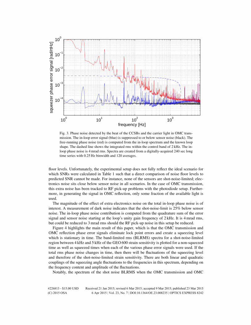
Fig. 3. Phase noise detected by the beat of the CCSBs and the carrier light in OMC trans-mission. The in-loop error signal (blue) is suppressed to or below sensor noise (black). Thefree-running phase noise (red) is computed from the in-loop spectrum and the known loopshape. The dashed line shows the integrated rms within the control band of 2 kHz. The in-loop phase noise is 4 mrad rms. Spectra are created from a digitally-acquired 240 sec longtime series with 0.25 Hz binwidth and 120 averages.
floor levels. Unfortunately, the experimental setup does not fully reflect the ideal scenario forwhich SNRs were calculated in Table 1 such that a direct comparison of noise floor levels topredicted SNR cannot be made. For instance, none of the sensors are shot-noise-limited; elec-tronics noise sits close below sensor noise in all scenarios. In the case of OMC transmission,this extra noise has been tracked to RF pick-up problems with the photodiode setup. Further-more, in generating the signal in OMC reflection, only some fraction of the available light isused.
The magnitude of the effect of extra electronics noise on the total in-loop phase noise is ofinterest. A measurement of dark noise indicates that the shot-noise-limit is 25% below sensornoise. The in-loop phase noise contribution is computed from the quadrature sum of the errorsignal and sensor noise starting at the loop’s unity gain frequency of 2 kHz. It is 4 mrad rms,but could be reduced to 3 mrad rms should the RF pick-up noise in this setup be reduced.
Figure 4 highlights the main result of this paper, which is that the OMC transmission andOMC reflection phase error signals eliminate lock point errors and create a squeezing levelwhich is stationary in time. The band-limited rms (BLRMS) spectra for a shot-noise-limitedregion between 4 kHz and 5 kHz of the GEO 600 strain sensitivity is plotted for a non-squeezedtime as well as squeezed times when each of the various phase error signals were used. If thetotal rms phase noise changes in time, then there will be fluctuations of the squeezing leveland therefore of the shot-noise-limited strain sensitivity. There are both linear and quadraticcouplings of the squeezing angle fluctuations to the frequencies in this spectrum, depending onthe frequency content and amplitude of the fluctuations.
Notably, the spectrum of the shot noise BLRMS when the OMC transmission and OMC
#226813 - $15.00 USD Received 21 Jan 2015; revised 6 Mar 2015; accepted 9 Mar 2015; published 23 Mar 2015 (C) 2015 OSA 6 Apr 2015 | Vol. 23, No. 7 | DOI:10.1364/OE.23.008235 | OPTICS EXPRESS 8242

0 2 4 6 8 10 1210
−1
100
101
frequency [Hz]
norm
aliz
ed B
LRM
S
No squeezingPick−offOMC reflectedOMC transmitted
Fig. 4. Amplitude spectra of the band-limited-rms of strain sensitivity in a shot-noise-limited frequency band from 4 kHz to 5 kHz. Stability of the squeezing level when usingthe OMC transmission and OMC reflection signals is demonstrated. The increase in fluctu-ations of the squeezing level when the standard pick-off signal is used is due to lock pointerrors from HOMs. All spectra are normalized to the mean of the non-squeezed spectraand the relative levels indicate the amount of squeezing present. Note, however, that thesqueezing level is not always perfectly steady in time, so the levels in this figure do notnecessarily represent the best possible squeezing.
reflection signals are used is no different than that from the non-squeezed time. Only the DClevel differs, which is the desired effect of squeezing. Furthermore, this demonstrates that thetotal rms phase noise from in-band and RF frequencies is very stable on these time scales. Theeffect of lock point errors from the pick-off signal is largely observed at frequencies below6 Hz where the suspended output optics are swinging and altering the spatial distribution ofHOMs on the sensor. These high levels of phase noise are not so frequent, so the effect on theaverage squeezing level is small. Nonetheless, stationarity of the data is of great importance forgravitational wave searches.
Table 2. Phase noises from known sources when the OMC transmitted signal is used. Thequadrature sum is 16.1 mrad rms.
source rms phase [mrad]in-loop: up to 2 kHz 4audio: 2 kHz – 45 kHz 13RF: 14.9 MHz MI sidebands 6.7RF: 9 MHz SRC sidebands 5.5
Finally, Table 2 presents a break down of the known phase noise contributions from differentfrequency bands. The audio band phase noise comes from computing the square differencebetween the signal and the sensor noise in the OMC transmitted signal from a measurement out
#226813 - $15.00 USD Received 21 Jan 2015; revised 6 Mar 2015; accepted 9 Mar 2015; published 23 Mar 2015 (C) 2015 OSA 6 Apr 2015 | Vol. 23, No. 7 | DOI:10.1364/OE.23.008235 | OPTICS EXPRESS 8243

to 45 kHz. Above 45 kHz, the signal is sensor-noise-limited. Phase noise from the 1% of RFsidebands that get transmitted through the OMC is computed [9] based on a measurement of thepower in the sidebands and the 5% ratio of contrast defect to dark fringe offset. Upon addingthese contributions incoherently, we find that we have a total known phase noise of 16.1 mradrms. Phase noises which cannot be measured directly such as phase noise in the frequency bandabove 45 kHz and lock point errors are not included. An out-of-loop measurement of phasenoise when using the OMC transmitted signal indicates the total phase noise is 37± 12 mradrms.
5. Discussion
Table 3 shows a summary of the various experimental parameters that play a role in determin-ing the quality of each of the phase error signals. The most important new implications that thiswork generates for interferometer design are related to the OMC and PD readout electronics.The OMC finesse and the CCSB frequency can be selected to allow a greater fraction of theCCSBs to be transmitted through the OMC than the current 1% transmission at GEO 600. Atrade-off must be reached, however, between lowering the OMC finesse to let more CCSBsthrough and preserving its function as a filter for both HOMs and the interferometer RF side-bands. There are also technical limitations to how low of a frequency the CCSBs can be. Be-cause the CCSBs have the same polarization as the squeezed field, power noise on the CC fieldthat extends into the GW frequency band can reduce the squeezing generated at the OPA byseeding on top of the vacuum seed. Some of this power noise could be alleviated by stabilizingthe CC laser.
Table 3. Important aspects to take into consideration when selecting which of the threesqueezing angle error signals to use and when thinking about how to improve them.
Pick-off OMC refl. OMC trans.HOMs (carrier) ×HOMs (MI SBs) ×HOMs (alignmnent) × ×CCSB frequency ×CCSB amplitude × × ×MI SB amplitude ×Pick-off fraction ×OMC finesse ×
Another aspect of using the OMC transmitted phase signal is that the information is carriedon the same light that carries the GW signal. To maintain the highest possible detection ef-ficiency, the two signals must be detected using the exact same PD(s). While DC readout ofthe GW signal requires only low-noise DC electronics, low-noise RF electronics are neededin addition in order to recover the squeezer phase error signal. This introduces the challengeof having to design and build dual low noise DC and RF readout electronics that are also notsusceptible to RF pick-up. This represents current on-going work at GEO 600.
Although the OMC reflected phase signal is a good option for GEO 600, it is not necessarilythe case for other detectors. The amount of MI sideband HOMs will need to be evaluated foreach individual experimental setup. Also, the MI sidebands do intrinsically contribute to phasenoise at RF frequencies and a trade-off in the level of MI sidebands is required. In addition, itshould be noted that although the SNR argument based on shot noise is irrelevant for GEO 600at the moment, it could be meaningful in the future and for different detectors.
#226813 - $15.00 USD Received 21 Jan 2015; revised 6 Mar 2015; accepted 9 Mar 2015; published 23 Mar 2015 (C) 2015 OSA 6 Apr 2015 | Vol. 23, No. 7 | DOI:10.1364/OE.23.008235 | OPTICS EXPRESS 8244

A nice side effect of eliminating the use of the pre-OMC pick-off for a phase signal is thatoptical losses can be reduced. Although the pick-off mirror is required for sensing some ofthe angular degrees of freedom of the interferometer, a lower pick-off fraction can be affordedwhen the light does not need to be shared with a PD for squeezer phase sensing.
Finally, although we use a noise lock loop to counteract lock point errors, it cannot fullycompensate for all of the errors from the pick-off signal due to its limited usable bandwidth ofat most 100 mHz. This limitation comes from the implementation of the noise lock, which is todither the squeezing phase at 11.6 Hz. Higher bandwidth could only come from increasing thedither amplitude, but this itself would add to the rms phase noise. The noise lock loop is thuslimited to control unsensed drifts of the squeezing phase only on slow time scales. Upon usingthe OMC transmitted signal, the noise lock loop corrects for drifts of the squeezing angle onthe order of tens of mrad over hour time scales. One underlying cause of these drifts is the factthat the CCSBs are imbalanced. Any change in the relative amplitudes of the CCSBs results inan offset to the locking point. This may arise from changes in non-linear gain which is itselfsusceptible to influences such as changing laser power.
The phase signals in OMC reflection and OMC transmission have each been used for stan-dard squeezing operation at GEO 600 at different times since 2011. The greater part of the 11month period reported in Ref. [7] used the OMC reflection signal, and since the last coupleof months of that run, the OMC transmitted signal has been in permanent use. After a newsignal recycling mirror was installed at GEO 600 which increased the amount of HOMs at theoutput port and increased lock point errors, the use of these new signals was a critical step forachieving stable squeezing.
6. Conclusion
We proposed two new methods of generating an error signal for matching the longitudinalphase of squeezed states of vacuum to that of the output field of a laser interferometer forgravitational-wave detection. We experimentally compared both of the new methods to the so-far standard method and the new methods are found to be superior. As the main result of thiswork, we showed that squeezing phase control using either of the new signals eliminates lockpoint errors and greatly improves the squeezing level stationarity. We discussed other featuresand advantages of the new methods which contribute to a higher level of observed squeezingand considered some implications for the design of future squeezed-vacuum applications. Hav-ing also demonstrated the new methods in long-term application at GEO 600, we conclude thatthey are a pivotal development towards realizing stable squeezing of 6 dB or more in advanceddetectors and beyond.
Acknowledgments
The authors are grateful for support from the Science and Technology Facilities Council(STFC), the University of Glasgow in the UK, the Bundesministerium fur Bildung undForschung (BMBF), and the state of Lower Saxony in Germany. This work was partly sup-ported by the Deutsche Forschungsgemeinschaft, DFG grant SFB/Transregio 7 GravitationalWave Astronomy. Additionally, we thank Roman Schnabel for leading the effort of providingthe squeezer used at GEO 600; Alexander Khalaidovski, Christian Graf, and Nico Lastzka fortheir work in building the squeezer and its automation system; Lisa Barsotti and Sheila Dwyerfor their respective visits and helpful input; Keita Kawabe for his thoughtful comments on thismanuscript; and Michael Weinert, Volker Kringel, Marc Brinkmann and Walter Graß for theirwork in keeping the GEO 600 interferometer in a good running state for this experiment. Thisdocument has been assigned LIGO document number LIGO-P1400150.
#226813 - $15.00 USD Received 21 Jan 2015; revised 6 Mar 2015; accepted 9 Mar 2015; published 23 Mar 2015 (C) 2015 OSA 6 Apr 2015 | Vol. 23, No. 7 | DOI:10.1364/OE.23.008235 | OPTICS EXPRESS 8245
Related Documents