Product Manual 36633 (Revision B) Original Instructions PG-500 Case, Accumulator, and Power Cylinder Installation and Operation Manual

Welcome message from author
This document is posted to help you gain knowledge. Please leave a comment to let me know what you think about it! Share it to your friends and learn new things together.
Transcript

Product Manual 36633(Revision B)
Original Instructions
PG-500 Case, Accumulator, and Power Cylinder
Installation and Operation Manual

General Precautions
Read this entire manual and all other publications pertaining to the work to be performed before installing, operating, or servicing this equipment.
Practice all plant and safety instructions and precautions.
Failure to follow instructions can cause personal injury and/or property damage.
Revisions
This publication may have been revised or updated since this copy was produced. To verify that you have the latest revision, check manual 26311 , Revision Status & Distribution Restrictions of Woodward Technical Publications, on the publications page of the Woodward website:
www.woodward.com/publications The latest version of most publications is available on the publications page. If your publication is not there, please contact your customer service representative to get the latest copy.
Proper Use
Any unauthorized modifications to or use of this equipment outside its specified mechanical, electrical, or other operating limits may cause personal injury and/or property damage, including damage to the equipment. Any such unauthorized modifications: (i) constitute "misuse" and/or "negligence" within the meaning of the product warranty thereby excluding warranty coverage for any resulting damage, and (ii) invalidate product certifications or listings.
Translated Publications
If the cover of this publication states "Translation of the Original Instructions" please note:
The original source of this publication may have been updated since this translation was made. Be sure to check manual 26311 , Revision Status & Distribution Restrictions of Woodward Technical Publications, to verify whether this translation is up to date. Out-of-date translations are marked with . Always compare with the original for technical specifications and for proper and safe installation and operation procedures.
Woodward reserves the right to update any portion of this publication at any time. Information provided by Woodward is believed to be correct and reliable. However, no responsibility is assumed by Woodward unless otherwise expressly undertaken.
Copyright © Woodward 1984 All Rights Reserved
Manual 36633 PG-500 Case, Accumulator, and Power Cylinder
Woodward i
Contents
WARNINGS AND NOTICES ............................................................................ III
ELECTROSTATIC DISCHARGE AWARENESS ................................................. IV
CHAPTER 1. GENERAL INFORMATION ........................................................... 1 Introduction ............................................................................................................. 1 Description .............................................................................................................. 1 Optional Equipment ................................................................................................ 1 PG Governor Heat Exchanger (Remote Only) ....................................................... 2 Booster Servomotor ................................................................................................ 2 References ............................................................................................................. 2
CHAPTER 2. INSTALLATION.......................................................................... 6 Introduction ............................................................................................................. 6 Receiving ................................................................................................................ 6 Storage ................................................................................................................... 6 Installation Requirements ....................................................................................... 6 Installation .............................................................................................................. 7 Fuel System Linkage .............................................................................................. 7 Hydraulic and Electrical Connections ..................................................................... 7 Booster Servomotor ................................................................................................ 7 Heat Exchanger ...................................................................................................... 7 Oil Supply ............................................................................................................... 8 Oils for Hydraulic Controls ...................................................................................... 8
CHAPTER 3. OPERATION AND ADJUSTMENT ............................................... 11 Introduction ........................................................................................................... 11 Initial Operation .................................................................................................... 11 Adjustments .......................................................................................................... 11 Compensation Needle Valve Adjustments ........................................................... 11
CHAPTER 4. PRINCIPLES OF OPERATION ................................................... 13 Introduction ........................................................................................................... 13 Amplifier Section ................................................................................................... 13 Governor Section .................................................................................................. 15 PG-500 Fuel Setting ............................................................................................. 17 Increase of Speed Setting or Load ....................................................................... 17 Decrease of Speed Setting or Load ..................................................................... 17 Compensation Cutoff ............................................................................................ 17
CHAPTER 5. MAINTENANCE ....................................................................... 18 Governor Oil ......................................................................................................... 18 Troubleshooting .................................................................................................... 18 Repair and Disassembly ....................................................................................... 19
CHAPTER 6. PARTS INFORMATION ............................................................. 20 Parts Replacement Information ............................................................................ 20
CHAPTER 7. PRODUCT SUPPORT AND SERVICE OPTIONS ........................... 29 Product Support Options ...................................................................................... 29 Product Service Options ....................................................................................... 29 Returning Equipment for Repair ........................................................................... 30 Replacement Parts ............................................................................................... 30 Engineering Services ............................................................................................ 31 Contacting Woodward’s Support Organization .................................................... 31 Technical Assistance ............................................................................................ 32

PG-500 Case, Accumulator, and Power Cylinder Manual 36633
ii Woodward
Illustrations and Tables Figure 1-1. PGA-500 Governor .............................................................................. 3 Figure 1-2. Location of PG-500 Connections ......................................................... 3 Figure 1-3. Lifting Sling for PG-500 Governor ........................................................ 4 Figure 1-4. Outline Drawing of PGA-500 Governor ................................................ 5 Figure 2-1. Viscosity and Operating Temperature of Oils .................................... 10 Figure 2-2. Equivalent Viscosities for Lubricating Oils ......................................... 10 Figure 4-1. Schematic of PG-500 ......................................................................... 14 Figure 6-1. Parts for PG-500 Case, Accumulator, and Power Cylinder ............... 21 Figure 6-2. Parts for Relay Piston, Relay Valve Assemblies ............................... 22 Figure 6-3. Parts for Output and Reducing Valve Assemblies ............................. 24 Figure 6-4. Parts for Drive and Pump Assemblies ............................................... 25 Figure 6-5. Parts for Servo Assembly................................................................... 26 Figure 6-6. Parts for Accumulator Assembly ........................................................ 27 Figure 6-7. Parts for Optional Vibration Resistant Accumulator Assembly .......... 28
Manual 36633 PG-500 Case, Accumulator, and Power Cylinder
Woodward iii
Warnings and Notices Important Definitions
This is the safety alert symbol. It is used to alert you to potential personal injury hazards. Obey all safety messages that follow this symbol to avoid possible injury or death.
DANGER—Indicates a hazardous situation which, if not avoided, will result in death or serious injury.
WARNING—Indicates a hazardous situation which, if not avoided, could result in death or serious injury.
CAUTION—Indicates a hazardous situation which, if not avoided, could result in minor or moderate injury.
NOTICE—Indicates a hazard that could result in property damage only (including damage to the control).
IMPORTANT—Designates an operating tip or maintenance suggestion.
Overspeed / Overtemperature /
Overpressure
The engine, turbine, or other type of prime mover should be equipped with an overspeed shutdown device to protect against runaway or damage to the prime mover with possible personal injury, loss of life, or property damage.
The overspeed shutdown device must be totally independent of the prime mover control system. An overtemperature or overpressure shutdown device may also be needed for safety, as appropriate.
Personal Protective Equipment
The products described in this publication may present risks that could lead to personal injury, loss of life, or property damage. Always wear the appropriate personal protective equipment (PPE) for the job at hand. Equipment that should be considered includes but is not limited to: Eye Protection Hearing Protection Hard Hat Gloves Safety Boots Respirator
Always read the proper Material Safety Data Sheet (MSDS) for any working fluid(s) and comply with recommended safety equipment.
Start-up
Be prepared to make an emergency shutdown when starting the engine, turbine, or other type of prime mover, to protect against runaway or overspeed with possible personal injury, loss of life, or property damage.
Automotive Applications
On- and off-highway Mobile Applications: Unless Woodward's control functions as the supervisory control, customer should install a system totally independent of the prime mover control system that monitors for supervisory control of engine (and takes appropriate action if supervisory control is lost) to protect against loss of engine control with possible personal injury, loss of life, or property damage.

PG-500 Case, Accumulator, and Power Cylinder Manual 36633
iv Woodward
Battery Charging Device
To prevent damage to a control system that uses an alternator or battery-charging device, make sure the charging device is turned off before disconnecting the battery from the system.
Electrostatic Discharge Awareness
Electrostatic Precautions
Electronic controls contain static-sensitive parts. Observe the following precautions to prevent damage to these parts: Discharge body static before handling the control (with power to
the control turned off, contact a grounded surface and maintain contact while handling the control).
Avoid all plastic, vinyl, and Styrofoam (except antistatic versions) around printed circuit boards.
Do not touch the components or conductors on a printed circuit board with your hands or with conductive devices.
To prevent damage to electronic components caused by improper handling, read and observe the precautions in Woodward manual 82715, Guide for Handling and Protection of Electronic Controls, Printed Circuit Boards, and Modules.
Follow these precautions when working with or near the control. 1. Avoid the build-up of static electricity on your body by not wearing clothing
made of synthetic materials. Wear cotton or cotton-blend materials as much as possible because these do not store static electric charges as much as synthetics.
2. Do not remove the printed circuit board (PCB) from the control cabinet unless absolutely necessary. If you must remove the PCB from the control cabinet, follow these precautions:
Do not touch any part of the PCB except the edges. Do not touch the electrical conductors, the connectors, or the
components with conductive devices or with your hands. When replacing a PCB, keep the new PCB in the plastic antistatic
protective bag it comes in until you are ready to install it. Immediately after removing the old PCB from the control cabinet, place it in the antistatic protective bag.
Manual 36633 PG-500 Case, Accumulator, and Power Cylinder
Woodward 1
Chapter 1. General Information
Introduction This manual describes the PG-500 case, accumulator, and power cylinder operation. Information is provided on governor installation, adjustments, and maintenance. This manual only gives information pertaining to the PGA/PGG-500, not to any of the PGA-EG/PGG-EG/PG-EG-500 units. Refer to manual 36637 for more information.
Description The PG-500 assembly is a PG-type governor and an integral, hydraulic amplifier unit. The large accumulator and oil pump supply high-pressure oil (1930 kPa/ 280 psi) to the power servo. The power servo is differential in operation, using oil pressure to move it in either the increase-fuel or decrease-fuel direction. Oil flow to or from the power servo is controlled by a relay valve. The power servo controls the rotation of the terminal shaft. In operation, a centrifugal-flyweight head and pilot valve assembly senses speed changes, and controls the flow of governor oil to a relay cylinder. The relay cylinder positions the relay valve to control the power piston output position. A compensation system gives stability to the governing system. It includes the compensation needle valve, the compensation land of the pilot valve plunger, a buffer piston, and two buffer springs. A short description of the setting of governor speed is given in this manual to aid in the understanding of the basic operation.
Optional Equipment The PG-500 is designed for the PGE, PGA, PG-PL, PGG, and PGD column assemblies to meet a variety of applications. Different methods of setting speeds and optional equipment are available on the column assembly, for use by themselves or in combination with the PG-500. Optional equipment performs a secondary function, such as limiting engine load, controlling engine load to maintain constant power output for each speed adjustment, starting fuel limiting, permitting temporary overloads, etc. Accessories used on the PG-500 case assembly include the PG Governor Heat Exchanger and the Booster Servomotor.

PG-500 Case, Accumulator, and Power Cylinder Manual 36633
2 Woodward
PG Governor Heat Exchanger (Remote Only) The heat exchanger is used to lower governor oil temperature when the governor operates in high ambient temperatures. It should be used whenever the governor will go above 93 °C (200 °F) maximum operating temperature. When a governor heat exchanger is needed, it can be added to the PG-500 without change or conversion. Determine governor oil temperature by measuring, during steady-state operation, through the dip stick, oil filler opening.
Take care not to put the thermometer into the hole too far or it will interfere with governor servo parts, damaging the governor, the thermometer, or both.
Booster Servomotor The booster servomotor is used with the governor to help the prime mover start quickly by moving the governor output toward the maximum-fuel position at start-up. A high-output booster is necessary when used with the PG-500 governor.
References This manual is one of several that must be used to describe a model of the PG-500 governor. For help in selecting optional features of the PG-500 governor, or if field conversion is necessary, write or call one of the Woodward offices shown on the back of this manual. Manual Title 25071 Oils for Hydraulic Controls 25075 Commercial Preservation Packaging for Storage of Mechanical-
Hydraulic Controls 36036 Starting Fuel Limiter for PG Governors 36052 Magnetic Speed Pickups for PG, UG8 and UG-40 Governors 36404 Analysis and Correction of PG Governing Troubles 36601 Absolute Manifold Pressure Bias Load Control and Fuel Limiter 36604 PGA Marine Governor 36614 PG Governor Dial Type Speed Setting 36615 PG Governor Lever Type Speed Setting 36621 PG Governor Speed Droop Linkage 36627 PGG Governor 36630 Basic Load Control System for PG Governors 36637 Integral EG Actuator for PG Governors 36641 Governor Oil Heat Exchanger 36650 Solenoid Operated Shutdown Assembly 36651 Pressure Actuated Shutdown Assembly 36652 Automatic Safety Shutdowns and Alarms 36653 Pressure Actuated Shutdown for PGD and PGL Governors 36661 Manifold Gauge Pressure Fuel Limiter 36662 Torque Limit Control with Speed Droop 36684 Booster Servomotor 36685 PG Shutdown Solenoid 36686 Pneumatic Load Balance System for PGA Governors 36694 PG-PL Governors 36695 Manifold Air Pressure Bias Fuel Limiter (Single Barrel Model)

Manual 36633 PG-500 Case, Accumulator, and Power Cylinder
Woodward 3
Figure 1-1. PGA-500 Governor
Figure 1-2. Location of PG-500 Connections
PG-500 Case, Accumulator, and Power Cylinder Manual 36633
4 Woodward
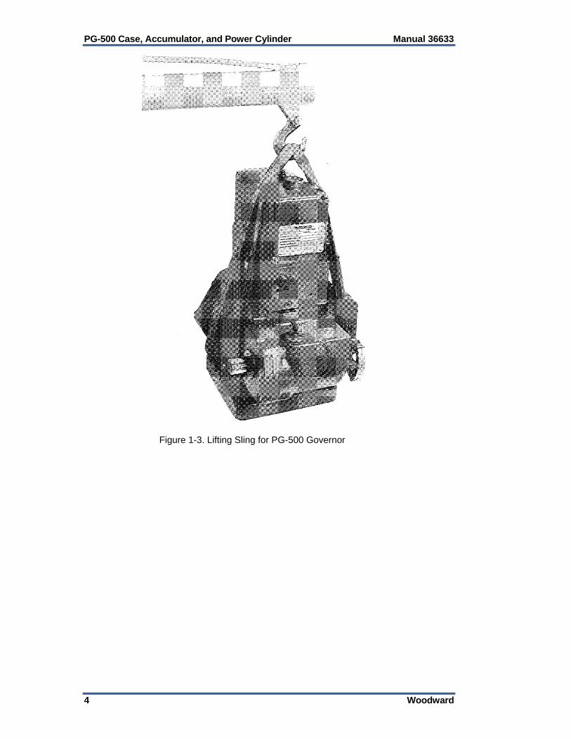
Figure 1-3. Lifting Sling for PG-500 Governor

Manual 36633 PG-500 Case, Accumulator, and Power Cylinder
Woodward 5
Figure 1-4. Outline Drawing of PGA-500 Governor

PG-500 Case, Accumulator, and Power Cylinder Manual 36633
6 Woodward
Chapter 2. Installation
Introduction This chapter covers receiving, storage, and installation requirements for the PG-500 governor (see outline drawing, Figure 1-4).
The engine, turbine, or other type of prime mover should be equipped with an overspeed shutdown device to protect against runaway or damage to the prime mover with possible personal injury, loss of life, or property damage. The overspeed shutdown device must be totally independent of the prime mover control system. An overtemperature or overpressure shutdown device may also be needed for safety, as appropriate.
Be careful when handling and installing the governor. Do not hit the drive shaft or output shaft. Rough handling can cause damage to seals, parts and adjustments.
Receiving The PG-500 governor is shipped from the factory in a vertical position, bolted to a wood platform. The governor has been calibrated at the factory to exact specifications, then drained of oil. A light film of oil covers the internal parts to help prevent rust. Calibration or internal cleaning is not needed before installation and operation. The drive shaft and output shafts are covered with a light film of oil, and a soft seal preservative can be applied at the customer's request. The seal preservative is removed before installation with a cloth and mineral spirits.
Storage If the PG-500 governor is to be in storage for a period of time, see the Woodward specification procedure, 25075, Commercial Preservation Packaging for Storage of Mechanical-Hydraulic Controls.
Installation Requirements See Figure 1-4 for overall dimensions, location of installation holes, hydraulic fitting sizes, output and drive shaft dimensions, and adjustment locations. Enough clearance must be allowed for installation, removal, and servicing of the governor. The governor oil drain should be easily accessible.

Manual 36633 PG-500 Case, Accumulator, and Power Cylinder
Woodward 7
Installation Install the PG-500 governor on the engine accessory drive pad. The drive shaft must slip into the accessory drive or mating coupling without force. Be careful not to push the drive shaft into the governor. Improper alignment or too tight a fit between any of the parts can result in wear or seizure. It can also cause jiggle in the governor output.
Damage to the drive shaft, drive shaft seal, or other parts of the governor may occur if the governor is dropped or set on the drive shaft or drive coupling.
Fuel System Linkage Correctly align and install the linkage between the fuel system and the PG-500 governor. The linkage must move freely and not have excessive backlash. Use approximately 2/3 governor output travel (28°) between idle and full fuel. Permit enough overtravel (typically 7°) so the governor can cause complete shutdown and give full fuel at full load. The governor output travel between shutdown position and idle speed must never be less than 5°. Many governors include an optional compensation cutoff and since this option cannot be seen without disassembly of the governor, this caution must be followed:
Due to the location of the compensation cutoff port in the relay servo wall, it is necessary to adjust the governor output linkage to use no less than 5° travel between shutdown and Idle.
Compensation cutoff is more completely described in Chapter 4, Principles of Operation.
Hydraulic and Electrical Connections Make all other hydraulic and electrical connections, if any, for the particular model PG-500 being installed. Use the correct Woodward manuals.
Booster Servomotor The booster servomotor is remotely located from the governor. Make all hydraulic connections from the booster to the governor (see Manual 36684, Booster Servomotor). A high-ratio (3:1) booster will be needed if used. Because of the large volume of oil needed to move the PG-500 servo, the booster limit screw should be adjusted to permit maximum booster servo output.
Heat Exchanger The heat exchanger is remotely located from the governor. Make all hydraulic connections for the heat exchanger to the governor (see manual 36641, Governor Oil Heat Exchanger).

PG-500 Case, Accumulator, and Power Cylinder Manual 36633
8 Woodward
Oil Supply Until the governor has been run and the accumulator filled, approximately four liters/quarts of oil will fill the governor. Governor oil capacity is 5.5 liters (5.8 quarts), and it is necessary to add oil after the governor is first started in order to restore oil to the full level mark on the dipstick. Check the oil level with the governor running. Use care when checking the oil level. Oil will splash from the test location during major governor transients.
Oils for Hydraulic Controls This information is provided as a guide in the selection of lubricating/hydraulic oil for governor use. Oil grade selection is based on viscosity change over the temperature range of the governor. The information also provides an aid in recognizing and correcting common problems associated with oil used in products manufactured by Woodward. It is not intended to suggest the selection of lubrication oil for the engine, turbine, or other type of prime mover being controlled. Governor oil lubricates and provides hydraulic power. The oil must have a viscosity index that allows it to perform over the operating temperature range and it must have the proper blending of additives to cause it to remain stable and predictable over this range. Governor fluid must be compatible with seal materials, (i.e., nitrile, polyacrylic and fluorocarbon). Many automotive and gas engine oils, industrial lubricating oils, and other oils of mineral or synthetic origin meet these requirements. Woodward governors are designed to give stable operation with most oils, if the fluid viscosity at the operating temperature span is within a 50 to 3000 SUS (Saybolt Universal Seconds) range. Ideally, at the normal operating temperature, viscosity should be between 100 and 300 SUS. Poor governor response or instability usually is an indication that the oil is too thick or too thin. Excessive component wear or seizure in a governor indicates the possibility of: 1. Insufficient lubrication caused by: A. An oil that flows slowly either when it is cold or during startup. B. An oil line restriction, obstructions within or bends in the line. C. No oil in the governor or governor oil level too low. 2. Contaminated oil caused by: A. Dirty oil containers B. A governor exposed to heating and cooling cycles, creating condensation of water in the oil. 3. Oil not suitable for the operating conditions. 4. An improper oil level which creates foamy, aerated oil. Operating a governor continuously beyond the high limit temperature of the oil will result in oil oxidation, identified by varnish or sludge deposits on the governor parts. To reduce oil oxidation, lower the governor operating temperature with a heat exchanger or other means, or change to an oil more oxidation resistant at the operating temperatures.
A loss of stable governor control and possible Prime Mover overspeed may result if the viscosity exceeds the 50 to 3000 SUS range. Overspeed can damage the engine and cause personal injury or death.
Manual 36633 PG-500 Case, Accumulator, and Power Cylinder
Woodward 9
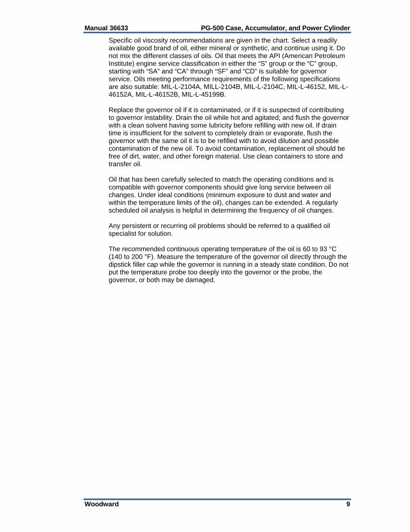
Specific oil viscosity recommendations are given in the chart. Select a readily available good brand of oil, either mineral or synthetic, and continue using it. Do not mix the different classes of oils. Oil that meets the API (American Petroleum Institute) engine service classification in either the “S” group or the “C” group, starting with “SA” and “CA” through “SF” and “CD” is suitable for governor service. Oils meeting performance requirements of the following specifications are also suitable: MIL-L-2104A, MILL-2104B, MIL-L-2104C, MIL-L-46152, MIL-L-46152A, MIL-L-46152B, MIL-L-45199B. Replace the governor oil if it is contaminated, or if it is suspected of contributing to governor instability. Drain the oil while hot and agitated; and flush the governor with a clean solvent having some lubricity before refilling with new oil. If drain time is insufficient for the solvent to completely drain or evaporate, flush the governor with the same oil it is to be refilled with to avoid dilution and possible contamination of the new oil. To avoid contamination, replacement oil should be free of dirt, water, and other foreign material. Use clean containers to store and transfer oil. Oil that has been carefully selected to match the operating conditions and is compatible with governor components should give long service between oil changes. Under ideal conditions (minimum exposure to dust and water and within the temperature limits of the oil), changes can be extended. A regularly scheduled oil analysis is helpful in determining the frequency of oil changes. Any persistent or recurring oil problems should be referred to a qualified oil specialist for solution. The recommended continuous operating temperature of the oil is 60 to 93 °C (140 to 200 °F). Measure the temperature of the governor oil directly through the dipstick filler cap while the governor is running in a steady state condition. Do not put the temperature probe too deeply into the governor or the probe, the governor, or both may be damaged.

PG-500 Case, Accumulator, and Power Cylinder Manual 36633
10 Woodward
Figure 2-1. Viscosity and Operating Temperature of Oils
Figure 2-2. Equivalent Viscosities for Lubricating Oils

Manual 36633 PG-500 Case, Accumulator, and Power Cylinder
Woodward 11
Chapter 3. Operation and Adjustment
Introduction This section describes the first startup and the basic adjustments of the PG-500 assembly.
Initial Operation Before the first startup of the PG-200/PG-300, be sure that all steps in Chapter 2 have been done and are correct.
Be prepared to make an emergency shutdown when starting the engine, turbine, or other type of prime mover, to protect against runaway or overspeed with possible personal injury, loss of life, or property damage.
Adjustments Normally, the only requirements for putting a new or repaired and calibrated governor into service are filling the governor with oil and adjusting the compensation needle valve to get maximum stability. All other operating adjustments are made during factory calibration to manufacturer's specifications. Further adjustment should not be needed. Do not make an internal adjustment of the governor unless completely familiar with the correct procedure.
Compensation Needle Valve Adjustments The compensation needle valve is an adjustable part of the compensation system. Its setting, which affects governor stability, is made according to the individual characteristics of the prime mover (see Figure 6-1, #9). To Adjust The Needle Valve: 1 With the prime mover operating at IDLE speed, open the compensation
needle valve until the governor begins to hunt. Let the governor hunt several minutes to remove trapped air in the hydraulic circuits.
If the governor has droop it may not hunt, even with the needle valve open. In almost every case the governor will hunt long enough to expel all of the air from the system. In some cases it may be necessary to upset the governor speed momentarily to cause the governor to hunt.

PG-500 Case, Accumulator, and Power Cylinder Manual 36633
12 Woodward
2. Close the compensation needle valve slowly until hunting just stops. Keep the needle valve open as far as possible to prevent slow governor response. The needle valve setting can be from 1/16 to 2 turns open. Do not close the needle valve tight. The governor cannot operate correctly in this condition.
3. Check the governor stability by manually disturbing the governor speed
setting. The compensation adjustment is satisfactory when the governor returns to speed with only a small overshoot or undershoot. Once the needle valve adjustment is correct, it is not necessary to change the setting unless there is a large permanent change in temperature that will change oil viscosity. Additional adjustment may be necessary if stability problems exist at full speed/full load conditions.

Manual 36633 PG-500 Case, Accumulator, and Power Cylinder
Woodward 13
Chapter 4. Principles of Operation
Introduction This chapter describes the operation of the basic elements of the PG-500 case, accumulator, and power cylinder assembly. A schematic drawing (Figure 4-1) shows the working relationship of the various parts. The speed setting is in the column assembly of the PG-500 governor, and only a short description is given to aid in understanding the basic operation. The description of operation is separated into two parts: Amplifier section Governor section
Amplifier Section Oil Pump and Accumulator The PG-500 has its own oil sump and oil pump. The drive shaft is driven at a speed proportional to the engine speed by a mechanical connection to the engine, and rotates the pump drive gear and the rotating bushing. As the inner pump drive gear turns the outer gear, oil from the sump is drawn by the gear teeth to the discharge side of the pump. Oil is pushed from the spaces between the gear teeth as the two gears mesh. Four check valves, two on the suction and two on the discharge side of the pump, permit the drive shaft to rotate in either direction without changing the PG-500 operation. If the pump gears were rotated in the opposite direction, the open check valves would close and the closed check valves would open. Oil on the discharge side of the pump pushes the accumulator piston against the accumulator spring. When piston movement uncovers the bypass port, excess pressure oil from the pump is returned to the sump through the pressurizing valve or heat exchanger. The accumulator is a reservoir for pressure oil and operates as a relief valve to provide at least 2068 kPa (300 psi) in this part of the hydraulic circuit. Heat Exchanger When the PG-500 is used with the optional heat exchanger, oil flows through the heat exchanger from the accumulator bypass. If the oil flow through the exchanger becomes restricted, and the pressure reaches 172 kPa (25 psi), the pressurizing valve opens and directs bypass oil back to sump. Power Servo The relay pilot valve controls the flow of 2068 kPa (300 psi) oil to the power servo assembly. The power piston, working through connecting linkage, controls the engine or turbine.

PG-500 Case, Accumulator, and Power Cylinder Manual 36633
14 Woodward
Figure 4-1. Schematic of PG-500
Manual 36633 PG-500 Case, Accumulator, and Power Cylinder
Woodward 15
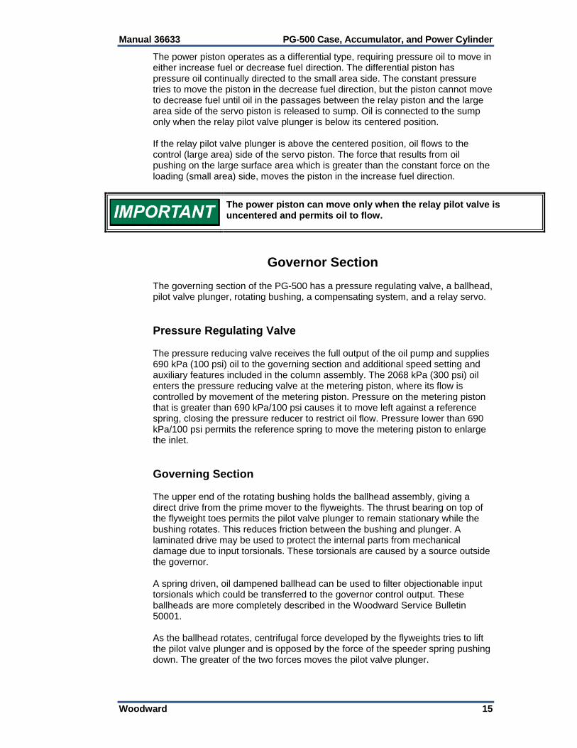
The power piston operates as a differential type, requiring pressure oil to move in either increase fuel or decrease fuel direction. The differential piston has pressure oil continually directed to the small area side. The constant pressure tries to move the piston in the decrease fuel direction, but the piston cannot move to decrease fuel until oil in the passages between the relay piston and the large area side of the servo piston is released to sump. Oil is connected to the sump only when the relay pilot valve plunger is below its centered position. If the relay pilot valve plunger is above the centered position, oil flows to the control (large area) side of the servo piston. The force that results from oil pushing on the large surface area which is greater than the constant force on the loading (small area) side, moves the piston in the increase fuel direction.
The power piston can move only when the relay pilot valve is uncentered and permits oil to flow.
Governor Section The governing section of the PG-500 has a pressure regulating valve, a ballhead, pilot valve plunger, rotating bushing, a compensating system, and a relay servo. Pressure Regulating Valve The pressure reducing valve receives the full output of the oil pump and supplies 690 kPa (100 psi) oil to the governing section and additional speed setting and auxiliary features included in the column assembly. The 2068 kPa (300 psi) oil enters the pressure reducing valve at the metering piston, where its flow is controlled by movement of the metering piston. Pressure on the metering piston that is greater than 690 kPa/100 psi causes it to move left against a reference spring, closing the pressure reducer to restrict oil flow. Pressure lower than 690 kPa/100 psi permits the reference spring to move the metering piston to enlarge the inlet. Governing Section The upper end of the rotating bushing holds the ballhead assembly, giving a direct drive from the prime mover to the flyweights. The thrust bearing on top of the flyweight toes permits the pilot valve plunger to remain stationary while the bushing rotates. This reduces friction between the bushing and plunger. A laminated drive may be used to protect the internal parts from mechanical damage due to input torsionals. These torsionals are caused by a source outside the governor. A spring driven, oil dampened ballhead can be used to filter objectionable input torsionals which could be transferred to the governor control output. These ballheads are more completely described in the Woodward Service Bulletin 50001. As the ballhead rotates, centrifugal force developed by the flyweights tries to lift the pilot valve plunger and is opposed by the force of the speeder spring pushing down. The greater of the two forces moves the pilot valve plunger.
PG-500 Case, Accumulator, and Power Cylinder Manual 36633
16 Woodward
When the prime mover is on speed at any speed setting, these forces are equal and the flyweights are in a vertical position. In this position the control land on the pilot valve plunger is centered over the control port in the rotating bushing. No oil, other than normal leakage, flows to or from the buffer compensation system or the relay servo. A change in either of these two forces moves the plunger from its centered position. The plunger is lowered (1) when the governor speed setting is unchanged but additional load slows the prime mover and governor (decreasing flyweight centrifugal force), or (2) when prime mover speed is not changed but speeder spring force is increased to raise the governor speed setting. In a similar way, the pilot valve plunger is raised (1) when governor speed setting is not changed but load is removed from the prime mover causing an increase in speed (hence an increase in flyweight centrifugal force), or (2) where prime mover speed is not changed but speeder spring force is reduced to lower the governor speed setting. When there is an underspeed condition, the plunger is lowered and pressure oil is directed into the buffer and compensation system and relay servo to raise the relay pilot valve plunger and cause the power piston to move to increase fuel. In an overspeed condition, the plunger is lifted permitting oil to drain from these areas to the sump. A return spring moves the relay piston to decrease and also lowers the relay pilot valve plunger, releasing oil from the left side of the power servo, allowing movement toward decrease fuel. With the governor acting directly on the fuel setting but sensing only actual engine or turbine speed, extensive overspeed or underspeed would occur at each speed change were it not for the buffer compensation system. The buffer piston, springs, and needle valve in the hydraulic circuit between the pilot valve plunger and the relay servo make up the system. When the flyweights move the pilot valve off the centered position, oil flow to or from the small power piston causes a pressure differential across the buffer piston and needle valve. The restriction of flow through the needle valve causes oil to flow through the path that houses the buffer piston and springs and causes the buffer piston to move against the buffer spring on the low pressure side of the piston. The amount of pressure differential across this system is controlled by the combination of needle valve opening and buffer spring scale. This pressure differential is sensed by the compensation land on the pilot valve, applying a force tending to oppose the change in force of the flyweights and move the pilot valve back to the centered position before the set speed is reached. This negative feedback (droop) reduces overshoot of the set speed and increases the stability of the control loop. The pressure differential gradually equalizes through the needle valve and the negative feedback dissipates, returning speed to the set point. The rate at which this happens is controlled by the needle valve opening and by buffer spring scale. Stronger buffer springs increase the effect, or gain, of the compensation, and the needle valve opening determines the recovery time. The smaller the opening, the slower the recovery to set speed. The buffer spring scale is predetermined and specified by the prime mover manufacturer or by Woodward.

Manual 36633 PG-500 Case, Accumulator, and Power Cylinder
Woodward 17
PG-500 Fuel Setting The following two examples show the sequence of events during a speed setting change or load change. The sequence occurs within the governor almost simultaneously rather than the step-by-step method described.
Increase of Speed Setting or Load Increasing speed setting or increasing load on the prime mover operating at any given speed has an identical effect for the purpose of description. In either of these conditions, the rotating flyweights move in due to an increase in speeder spring force, or by the decrease in centrifugal force caused by the decrease in prime mover speed as load is added. When the flyweights move in, the pilot valve plunger moves down and directs pressure oil into the compensation system, causing the buffer piston to move to the right and forcing the relay servo to move in the increase direction. As the prime mover accelerates to the set speed, the compensation force gradually reduces to offset the increasing flyweight force. This is done each time by balancing the pressures on both sides of the compensation land through the needle valve. This reduces overshoot to quickly establish stable, on-speed operation. When large changes in speed setting or load are made, the buffer piston moves far enough to open a bypass port in the buffer cylinder. This permits oil to flow directly to the relay servo and lets the governor respond quickly to large changes in speed setting or load.
Decrease of Speed Setting or Load The results of decreasing the speed setting or load on the prime mover are the same, and cause an action in the reverse of that described above. The flyweights move out, lifting the pilot valve plunger, permitting oil to drain from the compensating system and under the relay servo. The return spring causes the relay piston to move to decrease. The pressure differential across the compensation land this time causes a force down to help the speeder spring center the pilot valve plunger just before the prime mover has completely decelerated. This stops movement of the relay piston when the correct position is reached for the new lower speed setting or load.
Compensation Cutoff With large decreases in speed setting or large load decreases, the small power piston moves to the minimum fuel position and covers the compensation oil passage between the small servo and the needle valve to prevent normal balancing of the compensation pressures. This holds the buffer piston to the left of center and increases the level of the pressure sent to the upper side of the compensation land. The increased pressure differential, added to the compression of the speeder spring, temporarily increases the governor speed setting. The governor begins correcting as soon as the engine speed drops below this temporary speed setting and starts the relay piston restoring the fuel supply in time to prevent a large underspeed transient. This action is called compensation cut off. When the relay piston moves up and uncovers the compensation oil passage, normal compensation is again available and the engine keeps steady-state speed at the set speed of the governor.

PG-500 Case, Accumulator, and Power Cylinder Manual 36633
18 Woodward
Chapter 5. Maintenance
Governor Oil Use NEW OIL to fill the governor. Be sure that all containers used for governor oil storage are clean. Contaminated governor oil will cause early wear of plungers, bushings, gears, bearings, etc., and can cause rust and corrosion on springs and other internal parts. Under normal operating conditions, oil should be changed every 12 months. Oil must be changed more often if the unit operates under unusual temperature or dirt conditions. After the governor is put in service, the oil condition should be carefully monitored until a length of service can be established. A careful check of oil condition is suggested at least every three months until length of service is established. Any time the oil looks dirty or appears to be breaking down from contamination or high temperature, drain the governor oil while it is hot, flush with the lightest grade of the same oil, and refill the governor with new oil of the correct viscosity. (See oil viscosity table, Figure 2-1, or refer to Woodward manual 25071A, Recommended Oils for Governors, Actuators.)
Troubleshooting While a governor problem can show up as speed variations of the prime mover, not all speed variations of the prime mover are caused by a malfunction of the governor. When there is a problem, follow these procedures: 1. Check that the load is not beyond the load limit of the prime mover. 2. Be sure the engine cylinders are firing and the fuel injectors are operating
and correctly calibrated. 3. Check the linkage from the governor output to the fuel control. There must
be no binding and a minimum amount of backlash. 4. Check for fuel or steam pressure changes. 5. Be sure the compensating needle valve is set correctly. 6. Check the governor external speed adjusting devices. 7. Check governor oil pressure at the booster outlet port on the PG-500 case. 8. Check the governor oil and replace it if it is dirty. Sometimes the malfunction
of the governor can be corrected by flushing the governor with fuel oil or kerosene while the governor is operated through a cycle.
9. Check the drive to the governor for any evidence of the governor not being
aligned correctly on the installation pad, rough gears, or backlash. 10. Manual number 36404, Analysis and Correction of PG Governing Troubles,
covers governor malfunctioning and possible causes and corrective actions.
Manual 36633 PG-500 Case, Accumulator, and Power Cylinder
Woodward 19
Repair and Disassembly A governor can operate several years before it will need an overhaul if the oil is kept clean and the drive from the prime mover is smooth and does not have torsional vibration. If disassembly and repair become necessary, the work must be done by personnel trained in the correct repair procedures.
The accumulator spring (Figure 6-6 #157) is compressed and held in the accumulator assembly. Injury to person or damage to the equipment can result from careless disassembly of this unit. Place the accumulator assembly in an arbor press to permit a controlled rate of spring expansion. This does not apply to the newer-style accumulator, but be cautious if you are not sure which accumulator you have.

PG-500 Case, Accumulator, and Power Cylinder Manual 36633
20 Woodward
Chapter 6. Parts Information
Parts Replacement Information When ordering governor replacement parts, it is essential that the following information be given. Governor serial number and part number as given on the nameplate Manual number (this is manual 36633) Part reference number as given in the part list, name of part, or description
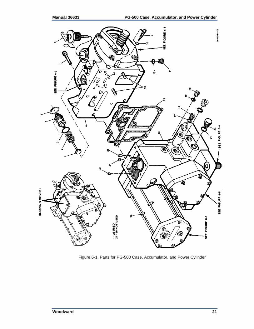
of part Parts List for Figure 6-1 Ref. No. Part Name ...................................... Qty 36633-1 Pressurizing valve plunger .................. 1 36633-2 Pressurizing valve spring .................... 1 36633-3 Preformed packing, .801 ID x .070 ..... 1 36633-4 Relief valve plug ................................. 1 36633-5 Retaining ring ...................................... 1 36633-6 Housing .............................................. 1 36633-7 Bolt, 12.7 dia. x 356 (metric) ............... 4 36633-8 Oil level gauge assembly .................... 1 36633-9 Needle Valve ...................................... 1 36633-10 Preformed packing, .301 ID x .070 ..... 1 36633-11 Plug .................................................... 1 36633-12 O-ring .................................................. 1 36633-13 Bolt, 12.7 x 330 (metric). Screws come from inside part number 6 ................... 3 36633-14 Dowel pin ............................................ 2 36633-15 Gasket ................................................ 1 36633-16 Case ................................................... 1 36633-17 O-ring .................................................. 1 36633-18 Plug .................................................... 1 36633-19 O-ring .................................................. 1 36633-20 Plug .................................................... 1 36633-21 O-ring .................................................. 2 36633-22 Plug (hex head) .................................. 2 36633-23 Plug .................................................... 1 36633-24 Plug .................................................... 1 36633-25 Locating pin ........................................ 2 36633-26 Block, accumulator stud, if used ......... 8
Manual 36633 PG-500 Case, Accumulator, and Power Cylinder
Woodward 21
Figure 6-1. Parts for PG-500 Case, Accumulator, and Power Cylinder

PG-500 Case, Accumulator, and Power Cylinder Manual 36633
22 Woodward
Parts List for Figure 6-2 Ref. No. Part Name ...................................... Qty 36633-51 Screw, .250 ......................................... 2 36633-53 Washer, .750 OD, .266 ID .................. 2 36633-54 Spring Cover ....................................... 1 36633-55 Preformed packing, 1.239 ID x .070 ... 1 36633-56 Loading spring .................................... 1 36633-57 Spring seat.......................................... 1 36633-58 Relay valve sleeve .............................. 1 36633-59 Relay valve spring .............................. 1 36633-60 Relay valve plunger assembly ............ 1 36633-61 Relay valve spring seat ....................... 1 36633-62 Relay valve plunger adjuster............... 1 36633-63 Relay valve lever assembly ................ 1 36633-64 Pin, drilled ........................................... 1 36633-65 Cotter pin ............................................ 2 36633-66 Power piston pin ................................. 1 36633-67 Power piston assembly ....................... 1 36633-68 Washer ............................................... 1 36633-69 Tail rod lift nut ..................................... 1
Figure 6-2. Parts for Relay Piston, Relay Valve Assemblies
Manual 36633 PG-500 Case, Accumulator, and Power Cylinder
Woodward 23
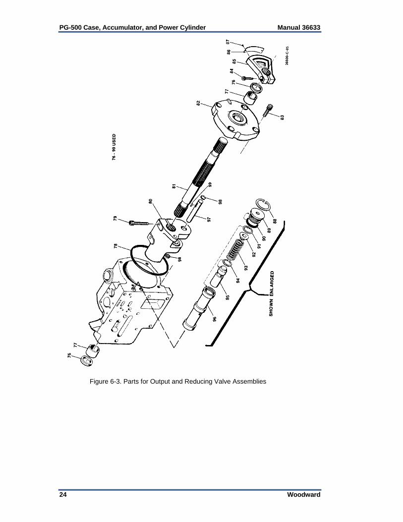
Parts List for Figure 6-3 Ref. No. Part Name ...................................... Qty 36633-76 Oil seal ................................................ 2 36633-77 Bushing ............................................... 2 36633-78 Preformed packing .............................. 1 36633-79 Screw .................................................. 2 36633-80 Output lever ......................................... 1 36633-81 Output shaft ......................................... 1 36633-82 Cover .................................................. 1 36633-83 Screw .................................................. 4 36633-84 Screw .................................................. 1 36633-85 Indicator .............................................. 1 36633-86 Scale ................................................... 1 36633-87 Drive screw ......................................... 2 36633-88 Retaining ring ...................................... 1 36633-89 Plug ..................................................... 1 36633-90 Preformed packing .............................. 1 36633-91 Retaining ring ...................................... 1 36633-92 Spring seat .......................................... 1 36633-93 Spring .................................................. 1 36633-94 Retaining ring ...................................... 1 36633-95 Reducing valve plunger ....................... 1 36633-96 Reducing valve sleeve ........................ 1 36633-97 Pin, connecting .................................... 1 36633-98 Retaining ring ...................................... 2
PG-500 Case, Accumulator, and Power Cylinder Manual 36633
24 Woodward
Figure 6-3. Parts for Output and Reducing Valve Assemblies

Manual 36633 PG-500 Case, Accumulator, and Power Cylinder
Woodward 25
Parts List for Figure 6-4
Ref. No. Part Name ......................................Qty36633-101 Not used .............................................. 1 36633-102 Not used .............................................. 1 36633-103 Not used .............................................. 1 36633-104 Not used .............................................. 1 36633-105 Needle bearing .................................... 1 36633-106 Not used .............................................. 1 36633-107 Not used .............................................. 1 36633-108 Key (if used) ........................................ 1 36633-109 Not used .............................................. 1 36633-110 Retaining ring ...................................... 2 36633-111 Pump element ..................................... 1 36633-112 Preformed packing .............................. 1
Ref. No. Part Name ...................................... Qty36633-113 Base ................................................... 1 36633-114 Oil seal ................................................ 1 36633-115 Gasket ................................................ 1 36633-116 Oil seal retainer .................................. 1 36633-117 Retaining ring ..................................... 1 36633-118 Bearings ............................................. 1 36633-119 Drive shaft .......................................... 1 36633-120 Bearing retainer .................................. 1 36633-121 Screw.................................................. 3 36633-122 Screw.................................................. 4 36633-123 Lockwire, .026 ...................... not shown 36633-124 Solid drive shaft .................................. 1
Figure 6-4. Parts for Drive and Pump Assemblies

PG-500 Case, Accumulator, and Power Cylinder Manual 36633
26 Woodward
Parts List for Figure 6-5 Ref. No. Part Name ...................................... Qty 36633-126 Retaining ring ...................................... 4 36633-127 Check valve assembly ........................ 4 36633-128 Preformed packing .............................. 4 36633-129 Buffer spring seat ................................ 1 36633-130 Buffer spring ....................................... 2 36633-131 Buffer piston ........................................ 1 36633-132 Preformed packing .............................. 1 36633-133 Buffer plug .......................................... 1 36633-134 Retaining ring ...................................... 1 36633-135 Preformed packing .............................. 1 36633-136 Connecting rod ................................... 1 36633-137 Connecting pin .................................... 1 36633-138 Servo piston ........................................ 1 36633-139 Servo cover ......................................... 1 36633-140 Screw .................................................. 8
Figure 6-5. Parts for Servo Assembly

Manual 36633 PG-500 Case, Accumulator, and Power Cylinder
Woodward 27
Parts List for Figure 6-6 Ref. No. Part Name ...................................... Qty 36633-151 Preformed packing .............................. 1 36633-152 Accumulator plate ............................... 1 36633-153 Preformed packing .............................. 2 36633-154 Accumulator stud ................................ 4 36633-154A Accumulator stud, long ........................ 4 36633-155 Accumulator tube ................................ 1 36633-156 Accumulator cylinder ........................... 1 36633-157 Accumulator spring ............................. 1 36633-158 Accumulator end ................................. 1 36633-159 Accumulator stud nuts ......................... 8 36633-160 Preformed packing .............................. 1 36633-161 Plug ..................................................... 1 36633-162 Plug ..................................................... 1 36633-162A Preformed Packing .............................. 1 36633-163 Drive screw ......................................... 2 36633-164 Warning plate ........................................... 1
Figure 6-6. Parts for Accumulator Assembly

PG-500 Case, Accumulator, and Power Cylinder Manual 36633
28 Woodward
Parts List for Figure 6-7 Ref. No. Part Name ...................................... Qty 36633-151 Preformed packing .............................. 2 36633-153 Preformed packing .............................. 1 36633-156 Accumulator cylinder .......................... 1 36633-157 Accumulator spring ............................. 1 36633-160 Preformed packing .............................. 1 36633-161 Plug .................................................... 1 36633- 162 Plug .................................................... 1 36633-162A Preformed packing ................................ 1 36633-176 Accumulator plate ............................... 1 36633-177 Flat washer ......................................... 4 36633-178 Bolt .500-13 x 8.8 inch ........................ 4 36633-179 Socket head screw, .500-13 x 1.750 ... 4 36633-180 Accumulator housing .......................... 1
Figure 6-7. Parts for Optional Vibration Resistant Accumulator Assembly

Manual 36633 PG-500 Case, Accumulator, and Power Cylinder
Woodward 29
Chapter 7. Product Support and Service Options
Product Support Options If you are experiencing problems with the installation, or unsatisfactory performance of a Woodward product, the following options are available: 1. Consult the troubleshooting guide in the manual. 2. Contact the OE Manufacturer or Packager of your system. 3. Contact the Woodward Business Partner serving your area. 4. Contact Woodward technical assistance via email
([email protected]) with detailed information on the product, application, and symptoms. Your email will be forwarded to an appropriate expert on the product and application to respond by telephone or return email.
5. If the issue cannot be resolved, you can select a further course of action to pursue based on the available services listed in this chapter.
OEM or Packager Support: Many Woodward controls and control devices are installed into the equipment system and programmed by an Original Equipment Manufacturer (OEM) or Equipment Packager at their factory. In some cases, the programming is password-protected by the OEM or packager, and they are the best source for product service and support. Warranty service for Woodward products shipped with an equipment system should also be handled through the OEM or Packager. Please review your equipment system documentation for details. Woodward Business Partner Support: Woodward works with and supports a global network of independent business partners whose mission is to serve the users of Woodward controls, as described here:
A Full-Service Distributor has the primary responsibility for sales, service, system integration solutions, technical desk support, and aftermarket marketing of standard Woodward products within a specific geographic area and market segment.
An Authorized Independent Service Facility (AISF) provides authorized service that includes repairs, repair parts, and warranty service on Woodward's behalf. Service (not new unit sales) is an AISF's primary mission.
A Recognized Engine Retrofitter (RER) is an independent company that does retrofits and upgrades on reciprocating gas engines and dual-fuel conversions, and can provide the full line of Woodward systems and components for the retrofits and overhauls, emission compliance upgrades, long term service contracts, emergency repairs, etc.
A current list of Woodward Business Partners is available at www.woodward.com/directory.
Product Service Options Depending on the type of product, the following options for servicing Woodward products may be available through your local Full-Service Distributor or the OEM or Packager of the equipment system. Replacement/Exchange (24-hour service) Flat Rate Repair Flat Rate Remanufacture
PG-500 Case, Accumulator, and Power Cylinder Manual 36633
30 Woodward
Replacement/Exchange: Replacement/Exchange is a premium program designed for the user who is in need of immediate service. It allows you to request and receive a like-new replacement unit in minimum time (usually within 24 hours of the request), providing a suitable unit is available at the time of the request, thereby minimizing costly downtime. This option allows you to call your Full-Service Distributor in the event of an unexpected outage, or in advance of a scheduled outage, to request a replacement control unit. If the unit is available at the time of the call, it can usually be shipped out within 24 hours. You replace your field control unit with the like-new replacement and return the field unit to the Full-Service Distributor. Flat Rate Repair: Flat Rate Repair is available for many of the standard mechanical products and some of the electronic products in the field. This program offers you repair service for your products with the advantage of knowing in advance what the cost will be. Flat Rate Remanufacture: Flat Rate Remanufacture is very similar to the Flat Rate Repair option, with the exception that the unit will be returned to you in “like-new” condition. This option is applicable to mechanical products only.
Returning Equipment for Repair If a control (or any part of an electronic control) is to be returned for repair, please contact your Full-Service Distributor in advance to obtain Return Authorization and shipping instructions. When shipping the item(s), attach a tag with the following information: return number; name and location where the control is installed; name and phone number of contact person; complete Woodward part number(s) and serial number(s); description of the problem; instructions describing the desired type of repair.
Packing a Control Use the following materials when returning a complete control: protective caps on any connectors; antistatic protective bags on all electronic modules; packing materials that will not damage the surface of the unit; at least 100 mm (4 inches) of tightly packed, industry-approved packing
material; a packing carton with double walls; a strong tape around the outside of the carton for increased strength.
To prevent damage to electronic components caused by improper handling, read and observe the precautions in Woodward manual 82715, Guide for Handling and Protection of Electronic Controls, Printed Circuit Boards, and Modules.
Replacement Parts When ordering replacement parts for controls, include the following information: the part number(s) (XXXX-XXXX) that is on the enclosure nameplate; the unit serial number, which is also on the nameplate.

Manual 36633 PG-500 Case, Accumulator, and Power Cylinder
Woodward 31
Engineering Services Woodward’s Full-Service Distributors offer various Engineering Services for our products. For these services, you can contact the Distributor by telephone or by email. Technical Support Product Training Field Service Technical Support is available from your equipment system supplier, your local Full-Service Distributor, or from many of Woodward’s worldwide locations, depending upon the product and application. This service can assist you with technical questions or problem solving during the normal business hours of the Woodward location you contact. Product Training is available as standard classes at many Distributor locations. Customized classes are also available, which can be tailored to your needs and held at one of our Distributor locations or at your site. This training, conducted by experienced personnel, will assure that you will be able to maintain system reliability and availability. Field Service engineering on-site support is available, depending on the product and location, from one of our Full-Service Distributors. The field engineers are experienced both on Woodward products as well as on much of the non-Woodward equipment with which our products interface. For information on these services, please contact one of the Full-Service Distributors listed at www.woodward.com/directory.
Contacting Woodward’s Support Organization For the name of your nearest Woodward Full-Service Distributor or service facility, please consult our worldwide directory published at www.woodward.com/directory. You can also contact the Woodward Customer Service Department at one of the following Woodward facilities to obtain the address and phone number of the nearest facility at which you can obtain information and service.
Products Used In Electrical Power Systems
Facility ---------------- Phone Number Brazil ------------- +55 (19) 3708 4800 China ----------- +86 (512) 6762 6727 Germany: Kempen ---- +49 (0) 21 52 14 51 Stuttgart -- +49 (711) 78954-510 India --------------- +91 (129) 4097100 Japan -------------- +81 (43) 213-2191 Korea -------------- +82 (51) 636-7080 Poland --------------- +48 12 295 13 00 United States ---- +1 (970) 482-5811
Products Used In Engine Systems
Facility ---------------- Phone Number Brazil ------------- +55 (19) 3708 4800 China ----------- +86 (512) 6762 6727 Germany ------- +49 (711) 78954-510 India --------------- +91 (129) 4097100 Japan -------------- +81 (43) 213-2191 Korea -------------- +82 (51) 636-7080 The Netherlands - +31 (23) 5661111 United States ---- +1 (970) 482-5811
Products Used In Industrial Turbomachinery
Systems Facility ---------------- Phone Number Brazil ------------- +55 (19) 3708 4800 China ----------- +86 (512) 6762 6727 India --------------- +91 (129) 4097100 Japan -------------- +81 (43) 213-2191 Korea -------------- +82 (51) 636-7080 The Netherlands - +31 (23) 5661111 Poland --------------- +48 12 295 13 00 United States ---- +1 (970) 482-5811
For the most current product support and contact information, please visit our website directory at www.woodward.com/directory.

PG-500 Case, Accumulator, and Power Cylinder Manual 36633
32 Woodward
Technical Assistance
If you need to contact technical assistance, you will need to provide the following information. Please write it down here before contacting the Engine OEM, the Packager, a Woodward Business Partner, or the Woodward factory:
General
Your Name
Site Location
Phone Number
Fax Number
Prime Mover Information
Manufacturer
Engine Model Number
Number of Cylinders
Type of Fuel (gas, gaseous, diesel, dual-fuel, etc.)
Power Output Rating
Application (power generation, marine, etc.)
Control/Governor Information
Control/Governor #1
Woodward Part Number & Rev. Letter
Control Description or Governor Type
Serial Number
Control/Governor #2
Woodward Part Number & Rev. Letter
Control Description or Governor Type
Serial Number
Control/Governor #3
Woodward Part Number & Rev. Letter
Control Description or Governor Type
Serial Number
Symptoms
Description
If you have an electronic or programmable control, please have the adjustment setting positions or the menu settings written down and with you at the time of the call.

Manual 36633 PG-500 Case, Accumulator, and Power Cylinder
Woodward 33

We appreciate your comments about the content of our publications.
Send comments to: [email protected]
Please reference publication 36633B.
PO Box 1519, Fort Collins CO 80522-1519, USA 1000 East Drake Road, Fort Collins CO 80525, USA Phone +1 (970) 482-5811 Fax +1 (970) 498-3058
Email and Website—www.woodward.com
Woodward has company-owned plants, subsidiaries, and branches, as well as authorized distributors and other authorized service and sales facilities throughout the world.
Complete address / phone / fax / email information for all locations is available on our website.
2012/11/Colorado
Related Documents