PG 1 Install Guide CT100 Caution • Turn off electricity to the HVAC system before installing or servicing thermostat or any part of the system. • Do not turn electricity back on until work is completed. • Do not short (jumper) across electric terminals at the control on the furnace or air conditioner to test the system. This may damage the thermostat. • All wiring must conform to local codes and ordinances. • This thermostat is designed for use with 4AA alkaline batteries and/or 24 VAC C-wire (or a 12-24 AC or DC source) and millivolt gas systems. Each thermostat relay load should be limited to 1.0 amp; higher amperage may cause damage to the thermostat. Caution To avoid electrical shock and to prevent damage to the furnace, air conditioner, and thermostat, disconnect the power supply before beginning work. This can be done at the circuit breaker. ENGLISH 1202-001-002 Power Grid status indicator top cover Touch screen Wire terminals Mode button button MENU Reset button HVAC selections switches bottom cover

Welcome message from author
This document is posted to help you gain knowledge. Please leave a comment to let me know what you think about it! Share it to your friends and learn new things together.
Transcript

PG 1
Install Guide CT100Caution
• Turn off electricity to the HVAC system before installing or servicing thermostat or any part of the system.�•�Do�not�turn�electricity�back�on�until�work�is�completed.•�Do�not�short�(jumper)�across�electric�terminals�at�the�control�on�the�furnace�or�air�conditioner�to�test�the�system.�This�may�damage�the�thermostat.•�All�wiring�must�conform�to�local�codes�and�ordinances.•�This�thermostat�is�designed�for�use�with�4AA�alkaline�batteries�and/or�24�VAC�C-wire�(or�a�12-24�AC�or�DC�source)�and�millivolt�gas�systems.�Each�thermostat�relay�load�should�be�limited�to�1.0�amp;�higher�amperage�may�cause�damage�to�the�thermostat.
Caution �To�avoid�electrical�shock�and�to�prevent�damage�to�the�furnace,�air�conditioner,�and�thermostat,�disconnect the power supply�before�beginning�work.�This�can�be�done�at�the�circuit�breaker.
ENGLISH1202-001-002
Power�Gridstatusindicator
top�cover
Touch�screen
Wireterminals
Modebutton
buttonMENU
Resetbutton
HVACselectionsswitches
bottom�cover

PG 2PG 2
WHAT TYPE WAS YOUR OLD SYSTEM?
First�verify�that�the�existing�system�operates�for�HEAT�and�COOl�[if�outside�temperature�is�below�60oF don’t�check�COOL]�.�Then�you�need�to�determine�what�type�of�HVAC�system�the�thermostat�will�be�controlling.��Heat�PUmp�or�Convention�System?
1)�Look�on�the�outside�compressor�unit�and/or�the�inside�air�handler�unit�for�the�words�“Heat�Pump”�which�uses�the�outside�compressor�for�heating�as�well�as�cooling�=�You�have�a�Heat�Pump.2)�A�heat�pump�needs�a�“changeover”�wire�to�change�from�heat�to�cool;�so�it�must�have�a�wire�connected�to�the�O�terminal�or�the�B�terminal�on�the�old�thermostat�=�You�have�a�Heat�Pump.Note�-�The�old�thermostat�may�have�an�emergency�wire�(E),�an�emergency�ON/OFF�switch,�and�an�EMER�on�light.�If�so,�be�sure�the�EMER�switch�is�turned�off�for�the�next�test.4)�Using�the�old�thermostat�in�HEAT�mode,�Increase�the�target�just�enough�to�turn�on�the�heat;�if�it�is�a�heat�pump,�the�outside�compressor�unit�will�be�running�in�heat.�=�You�have�a�Heat�Pump.5)�If�you�have�a�heat�pump,�you�may�also�have�another�source�of�heat�(auxiliary)�which�can�be�electric,�gas�or�oil.�You�must�determine�what�that�back�up�heat�is�so�you�can�set�the�thermostat�for�the�proper�system.
In�a�conventional�heating/cooling�system�there�is�a�single�source�of�heat�(electric,�gas�or�oil)�plus�an�outside�compressor�for�just�cooling.�There�will�not�be�an�O�or�B�or�E�wire.Often�the�home�owner�will�know�what�type�of�conventional�system�they�have.��Whichever�has�the�largest�energy�bill�is�the�heater.

PG 2
PG 3
TOOLS
You�will�need�a�small�Phillips�screwdriver�and�a�drill�with�3/16-in.�(4.8mm)�bit�for�wall�mounts.�
LOCATION��Replacement�installations�-�mount�the�CT100�in�place�of�the�
old�thermostat.��A�new�location�will�require�moving�your�wiring.For�new�installations�and�relocating�the�CT100�-��follow�the�guidelines�listed�below:�•�Locate�the�thermostat�on�an�inside�wall,�about�5�ft.�(1.5m)�above�the�floor,�and�in�a�room�that����is�used�often.•�Do�not�install�it�where�there�are�unusual�heating�conditions,�such�as:�in�direct�sunlight;�near�����a�lamp,�radio,�television,�radiator�register,�fireplace;�near�hot�water�pipes�in�a�wall;�or�near�a���stove�on�the�other�side�of�a�wall.•�Do�not�locate�in�unusual�cooling�conditions,�such�as:�on�a�wall���separating�an�unheated�room;�or�in�a�draft�from�a�stairwell,�door,���or�window.•�Do�not�locate�in�a�damp�area.�This�can�lead�to�corrosion�that�will�shorten�thermostat�life.� •�Do�not�locate�where�air�circulation�is�poor,�such�as:�in�a�corner,�an�alcove;�behind�an�open�door.�•�Do�not�install�the�CT100�until�all�construction�and�painting�has���been�completed.•�This�thermostat�does�not�require�leveling.
Good
5ft.(1.5m)

PG 4
REMOVE OLD UNIT
Switch OFF electricity to the HEATING and COOLING systems.� Then�follow�these�steps:•�Remove�cover�from�old�thermostat.�Most�are�snap-on�types�and�simply�pull�off.��Some�have�locking�screws�on�the�side�or�front.��These�must�be�loosened.��DO�NOT�remove�wires.��Note�the�letters�printed�near�the�terminals.��Attach�labels�(enclosed)�to�each�wire�for�identification.
Caution Read instructions carefully before removing any wiring from existing thermostat. Wires must be labeled before they are removed. THERE IS NO STANDARD COLOR CODE. When remov-ing wires from their terminals, ignore the color of the wires and LABEL THEM by the lettered terminal where they were screwed.
•�Label�the�wires�one�at�a�time.��You�must�label�all�the�wires�before�you�proceed.��•�With�all�wires�labeled,�remove�them�from�the�old�unit.•�Make�sure�the�wires�do�not�fall�back�inside�the�wall.��You�can�wind�them�around�a�pencil�to�keep�them�from�falling.•�Loosen�all�screws�on�the�old�thermostat�and�remove�it�from�the�wall.
R W
G

PG 4
PG 5
What wires do you have?�Make�sure�your�wires�are�labeled.�This�may�require�you�to�find�
the�‘other�end’�connection�for�each�wire�on�your�heating�or�air�conditioning�equipment�and�read�the�label�there.�Refer�to�the�Wire�Reference�page�at�end�of�install�section�for�better�understanding�of�wire�labels�from�different�HVAC�system�makers.
IMPORTANT: �The�CT100�runs�on�4�AA�alkaline�batteries�and/or�the�C�wire�if�available.�If�you�do�not�have�a�C�wire�you�can�run�a�new�wire�from�the�HVAC�or�use�a�standard�12-24V�[AC�or�DC]�wall�transformer.
IMPORTANT: If�you�have�both�RH�and�RC�you�need�to�remove�the�jumper�wire�between�these�2�terminals.
Prepare Wires
Please�follow�these�guidelines�for�safe�and�secure�wire�connections:•�You�will�need�at�least�2.6”�of�wire�for�each�of�your�connections�to�the�CT100.��•�If�you�do�not�have�enough�wire,�splice�additional�wire�to�allow�enough�slack.� •�Terminals�accept�wires�from�16-22awg.•�Fan�out�wires�below�the�hole�as�shown.•�Remove�insulation�1/8”�from�the�tip�of�each�wire.•�When�handling,�take�care�not�to�damage�the�labels�for�each�wire.
GC Y RW
2.6"
from�HVAC System
Wire�Terminals
Jumper�wire
Y RH RC G A

PG 6
Find�the�step-by-step�diagram�for�your�system � � ��������•�Select�the�reference�page�
with�your�wiring�diagram�and�set-up�information�below.
•�The�C-wire�is�optional�but�preferred�for�all�installations.�It�will�make�batteries�last�a�long�time.��(This�connection�is�shown�as�dotted�in�diagrams).��
•�Hot�Water�systems�accessories�are�on�Page�17.
•�If�your�combination�of�wires�is�not�shown,�you�can�use�the�wiring�table�at�the�end�of�the�install�section�to�find�your�connections.�If�additional�help�is�required,�please�contact�Technical�Support�at��888-721-0147.
G
�W�Y�RH�RC�G
5�WireHeat/Cool
From
HVAC
RCCY RHW
W�Y�R�G�4�Wire Heat/Cool
From
HVAC
GCY RW
�W�R�G 3�Wire Heat
From
HVAC
C R GW
From
HVAC
C W
W R
R
2�Wire Heat
WIRES
WIRES
WIRES
WIRES
GR
�Wn�Yn�R G Multi-stage�CoolMulti-Stage�Heat
From
HVAC
YnC Wn
B�or�O��AUXn�Yn R�G Multi-stage ��Heat�Pump�������w/�
Multi-stage�������Aux�Heat
From
HVAC
RC O
or
WnB GYnG
�B�or�O��Y�R�G 4�Wire�Heat�Pumpw/o�Aux�Heat
From
HVAC
RC O
or
YB
WIRES
WIRES
WIRES
Go�To�Page�16 Go�To�Page�17Go�To�Page�16
Go�To�Page�14 Go�To�Page�15 Go�To�Page�15Go�To�Page�14

PG 6
PG 7
•�“Fan�out”�wires�as�illustrated�with�CT100�below�the�wall�opening.��As�in�the�example:�fan�out�the�wires�so�that�the�C�wire�is�above�the�C�terminal,�the�W�above�the�W.�This�allows�the�CT100�to�fit�snug�to�the�wall.
Caution Do not allow wires to touch each other or parts on thermostat.
•�Position�the�wires�behind�the�CT100�and�up�over�the�terminal�area.•�Do�not�bunch�wires�behind�the�CT100.��Feed�any�slack�back�into�the�wall�opening.
Connect Your Wires
•�Connect�labeled�wires�only�to�a�terminal�with�the�same�letter�label.•�Insert�the�wire�in�the�terminal�well�and�tighten�the�screw�securely.NOTE:�If�you�wish�you�can�mount�the�CT100�to�the�wall�first,�and�then�connect�the�wires.•�The�CT100�can�be�externally�powered�with�a�power�source�rated�from�12V�to�24V,�AC�or�DC,�at�100ma�or�greater.�If�used,�connect�to�the�C�and�RH�terminals�(no�polarity).
from�HEAT/COOL�system
C B O W W2 Y Y2 RHRCG A
RHY G
C W

PG 8
Mount the CT100 to Wall
1.�Hold�the�CT100�against�the�wall,�with�the�wires�coming�over�the�top;�above�terminal�block.�The�CT100�will�cover�the�hole�in�the�wall.�2.�Position�CT100�for�best�appearance.�3.�Attach�the�CT100�to�the�wall�with�the�screws�provided.4.�If�you�are�mounting�the�CT100�to�sheet�rock�or�if�you�are�using�the�old�mounting�holes,�use�the�plastic�anchors�provided.�5.�Mark�first�and�drill�a�3/16-in.(4.8mm)�hole�for�the�insert�at�each�screw�
location,�then�mount�the�unit.
Wall
Wires
Wallanchor
CT100
from�HEAT/COOL�system
CWY
RH G
Place�wires�like�this
Screw�to�wall

PG 8
PG 9
HVAC Selection
�•�Set�the�HVAC TYPE�switch�in�the�NORMAL position�if�you�have�conventional�natural�gas,�propane,�oil,�or�electric�heat.��If�you�have�a�HEAT�PUMP�system,�set�the�HVAC TYPE�switch�to�HEAT PUMP.��They�are�located�in�the�battery�area.��•�Set�the�HEAT TYPE�switch�in�the�GAS position�if�you�have�normal�gas�or�oil�heat�or�if�you�have�a�heat�pump�with�gas�or�oil�auxiliary�heat.�Put�the�HEAT SOURCE�in�the ELEC�position�if�you�have�normal�electric�heat�or�if�you�have�a�heat�pump�with�electric�auxiliary�heat.�
IMPORTANT:�Press�the�RESET�button�(under�top�cover)�to�implement�the�HVAC�switch�selections.
Install 4 AA Batteries
•�Install�4�AA�alkaline�batteries�[required]�following�the�marked�polarity�in�the�battery�compartment.�Put�the�battery�in�negative�end�first�against�the�spring,�then�push�the�positive�end�in.� •�With�all�the�wires�connected�it�is�time�to�turn�the�AC�power�back�on.�Do�this�at�the�breaker�you�used�to�switch�it�off.�The�CT100�will�power-up�in�the�OFF�mode.�Your�CT100�is�not�configured�to�operate�your�HVAC�system�yet.��You�must�now�configure�your�thermostat�for�your�HVAC�system.
AAAA AA
AA
HEATPUMP
HVACTYPE
HVACTYPE
HEAT�TYPE
HEATTYPE
NORMAL GASELEC

PG 10
Caution Special Battery WarningAlways�replace�the�batteries�as�soon�as�the�“Low�Batt”�flashes.�The�thermostat�is�a�battery�powered�device.�You�must�be�responsible�to�replace�batteries�before�they�run�out.�Failure�to�replace�batteries�can�result�in�overheating�or�excessive�cooling�of�your�house.
•�Even�if�the�“Low�Batt”�indicator�does�not�flash,�you�should�always�replace�the�batteries�at�least�once�a�year.�Replacing�the�batteries�also�helps�to�prevent�leakage�that�can�corrode�and�damage�the�thermostat.
•�If�you�are�leaving�your�home�for�a�month�or�more,�you�should�replace�the�batteries�as�a�precaution�against�battery�failure�in�your�absence.
•�Always�use�new�alkaline�batteries.
•�Failing�to�replace�the�batteries,�when�necessary,�could�cause�the�thermostat�to�lose�power�or�malfunction.�If�the�thermostat�loses�power,�then�the�thermostat�will�not�control�the�temperature�which�could�result�in�your�HVAC�system�not�functioning�as�you�intended�and�lead�to�possible�damage�from�overheating�or�excessive�cooling.
•�If�the�thermostat�batteries�fail�with�the�heat�OFF,�this�can�result�in�NO�HEAT�and�possible�frozen�or�broken�pipes�and�water�damage.
•�If�the�thermostat�batteries�fail�with�the�cool�OFF,�this�can�result�in�NO�COOL�and�could�cause�possible�damage�or�excessive�temperatures.

PG 10
PG 11
HVAC Setup on Screen
IMPORTANT:�Make�sure�the�CT100�is�powered�up�and�the�mode�is�set�to�OFF.�Remember�that�the�two�HVAC�selection�switches�must�be�set�first�[pg�9].•�With�mode�in�OFF�press�MENU�and�touch�HVAC�SETUP.•�Use�+/-�icons�to�select�HVAC�SET�UP�number�on�screen.The�LCD�display�will�show�your�selection�and�indicate�the�number�of�stages�you�have�selected.�During�setup,�2nd STG will�blink�when�both�heat�and�cool�have�2nd�stages.
If you have a Normal HVAC system... HEAT and COOL select 12 stage HEAT, 1 stage COOL select 2 1 stage HEAT, 2 stage COOL select 3 2 stage HEAT, 2 stage COOL select 4
If you have a HEAT PUMP HVAC system...HEAT PUMP with no AUX heat select A2 stage HEAT PUMP with no AUX select b HEAT PUMP with AUX heat select C HEAT PUMP with 2 stage AUX heat select d 2 stage HEAT PUMP with AUX heat select E 2 stage HEAT PUMP with 2 stage AUX heat select F
HEAT2NDSTG
HVACSETUP
COOL

PG 12
Test Installation
Follow�these�procedures�to�verify�you�have�correctly installed�the�CT100.
TO CHECK FAN�(If�you�connected�the�G�wire):��Touch�the� �fan�icon�on�the�HOME�screen�to�turn�the�fan�ON. Verify�that�air�is�blowing�from�the�system.� Touch�the� �icon�again�to�return�to�AUTO.
TO CHECK HEAT Set�the�mode�to�HEAT by�pressing�the�MODE�button�until�HEAT is�displayed.�Touch�the�temperature�display�to�bring�up�the�MANUAL�screen.�Touch�the�+�icon�and�raise�the�target�temp�to�90oF;�allow�the�system�2�minutes�to�respond.�Verify�that�heat�is�blowing�from�the�system.�Return�the�Target�Temperature�to�a�normal�setting.�Return�mode�to�OFF by�pressing�the�mode�button.�NOTE:�If�you�have�a�heat�pump,�leave�in�off�for�4�minutes�before�checking�COOL.�
TO CHECK COOL��(do�not�operate�AC�if�the�outside�temp�is�below�65oF)�Set�the�mode�to�COOL by�pressing�the�MODE�button�until�COOL is�displayed.Touch�the�-�icon�and�lower�cool�Target�Temperature�to�50oF.�Allow�the�system�5�minutes�to�respond.�Verify�that�cool�air�is�blowing�from�the�system.�Return�the�Target�Temperature�to�a�normal�setting. Return�mode�to�OFF by�pressing�the�mode�button.�
FAN
MODE
MENU
MODE
FLINK
RADIO
TARGET TEMP
1
HEAT
AUTO
PG 12
PG 13
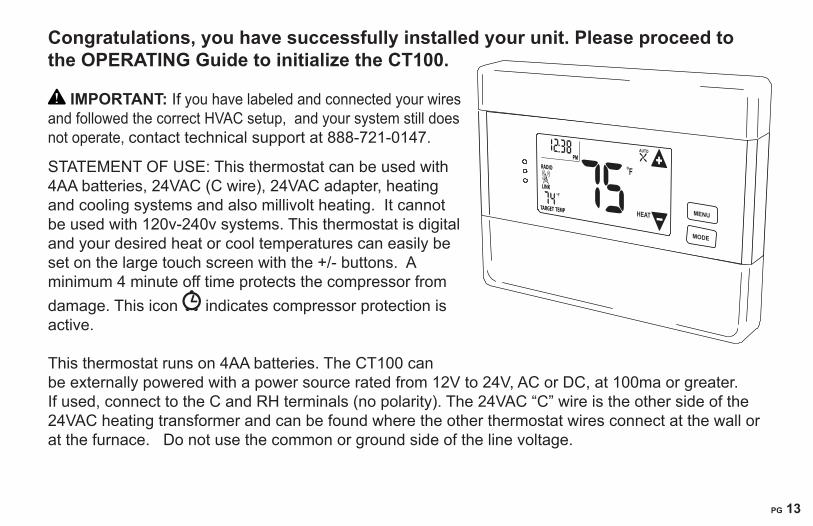
Congratulations, you have successfully installed your unit. Please proceed to the OPERATING Guide to initialize the CT100.
IMPORTANT:�If�you�have�labeled�and�connected�your�wires�and�followed�the�correct�HVAC�setup,��and�your�system�still�does�not�operate,�contact�technical�support�at�888-721-0147.�
STATEMENT�OF�USE:�This�thermostat�can�be�used�with�4AA�batteries,�24VAC�(C�wire),�24VAC�adapter,�heating�and�cooling�systems�and�also�millivolt�heating.��It�cannot�be�used�with�120v-240v�systems.�This�thermostat�is�digital�and�your�desired�heat�or�cool�temperatures�can�easily�be�set�on�the�large�touch�screen�with�the�+/-�buttons.��A�minimum�4�minute�off�time�protects�the�compressor�from�damage.�This�icon� �indicates�compressor�protection�is�active.��
This�thermostat�runs�on�4AA�batteries.�The�CT100�can�be�externally�powered�with�a�power�source�rated�from�12V�to�24V,�AC�or�DC,�at�100ma�or�greater.�If�used,�connect�to�the�C�and�RH�terminals�(no�polarity).�The�24VAC�“C”�wire�is�the�other�side�of�the�24VAC�heating�transformer�and�can�be�found�where�the�other�thermostat�wires�connect�at�the�wall�or�at�the�furnace.���Do�not�use�the�common�or�ground�side�of�the�line�voltage.��
MENU
MODE
FLINK
RADIO
TARGET TEMP
1
HEAT
AUTO

PG 14
Step-by-step�wiring�diagrams
WIRES 2 Wire Heat GAS MILLIVOLT or 24VAC system
STEP�1�-�Connect�the�R�wire�to�the�RH�terminal.�� This�connects�the�heat�power.STEP�2�-�Connect�the�W�wire�to�the�W�terminal.� This�connects�the�heat.����������������STEP�3�-��Optional�-�Connect�the�C�wire�to�the�C�terminal.Your�heater�is�now�connected�to�the�CT100.��
Please�Go�To�Page�6��
WIRES 3 Wire Heat
STEP�1�-�Connect�the�R�wire�to�the�RH�terminal.�This�connects�the�heat�power.STEP�2�-�Connect�the�W�wire�to�the�W�terminal.�This�connects�the�heat.STEP�3�-�Connect�the�G�wire�to�the�G�terminal�on�the�thermostat.�This�connects�the�fan.STEP�4�-��Optional�-�Connect�the�C�wire�to�the�C�terminal. Your�system�is�now�connected�to�the�CT100.
Please�Go�To�Page�6
C�B�O�W�W2�Y�Y2 RH�RC�G�A�
POWER
HVAC�SYSTEM
THERMOSTAT
W RC
THERMOSTAT�TERMINALS
HVAC�SYSTEM
THERMOSTAT
C�B�O�W�W2�Y�Y2 RH�RC�G�A
POWERW R GC
THERMOSTAT�TERMINALS

PG 14
PG 15
W Y R G
WIRES 4 Wire Heat/Cool STEP�1�-�Connect�the�W�wire�to�the�W�terminal.��This�connects�the�heat.STEP�2�-�Connect�the�Y�wire�to�the�Y�terminal.�This�connects�the�cooling�compressor.STEP�3�-�Connect�the�RH�or�R�wire�to�the�RH�terminal.�This�connects�the�power.STEP�4�-�Connect�the�G�wire�to�the�G�terminal�on�the�thermostat.�This�connects�the�fan.STEP�5�-�Optional�-�Connect�the�C�wire�to�the�C�terminal. Your�HVAC�system�is�now�connected�to�the�CT100. �Please�Go�To�Page�6����
W Y RH RC G
WIRES 5 Wire HEAT/Cool
STEP�1�-�Connect�the�W�wire�to�the�W�terminal.��This�connects�the�heat.STEP�2�-�Connect�the�Y�wire�to�the�Y�terminal.�This�connects�to�the�cooling�compressor.STEP�3�-�Remove�the�jumper�between�RC�and�RH�terminals�[small�silver�wire].STEP�4�-�Connect�the�RH�wire�to�the�RH�terminal�and�the�RC�wire�to�the�RC�terminal.� This�connects�the�power.STEP�5�-�Connect�the�G�wire�to�the�G�terminal.�This�connects�the�fan.STEP�6�-�Optional�-�Connect�the�C�wire�to�the�C�terminal.
Your�HVAC�system�is�now�connected�to�the�CT100. Please�Go�To�Page�6��
HVAC�SYSTEM
THERMOSTAT�TERMINALS
C�B�O�W�W2�Y�Y2 RH�RC�G�A
POWER W Y R GC
HVAC�SYSTEM
THERMOSTAT�TERMINALS
C�B�O�W�W2�Y�Y2 RH�RC�G�A�
POWER W Y RH GC RC
*RC�and�RHdisconnected

PG 16Wn Yn R G Multi-stage Heat and Multi-stage Cool
The�CT100�can�handle�up�to�2�stages�of�HEAT�and�2�stages�of�COOL. STEP�1�-�Connect�the�W�and�W2�wires�to�the�W�terminals�respectively.� This�connects�the�stages�of�HEAT.STEP�2�-�Connect�the�Y�and�Y2�wires�to�the�Y�and�Y2�terminals�respectively.� This�connects�the�stages�of�COOL.STEP�3�-�Connect�the�RH�or�R�wire�to�the�RH�terminal.� This�connects�the�power.STEP�4�-�Connect�the�G�wire�to�the�G�terminal.� This�connects�the�fan.STEP�5�-��Optional�-�Connect�the�C�wire�to�the�C�terminal.Your�HVAC�system�is�now�connected�to�the�CT100.�
�Please�Go�To�Page�6������
Heat Pump (heat/cool) without Auxiliary Heat STEP�1�-�Connect�O�wire�to�the�O�terminal�or�B�wire�to�the�B�terminal.� This�connects�the�change-over�valve.�IMPORTANT NOTE: If�you�have both�O�and�B�-�connect�only�the�O�wire�to�the�O�terminal�and��DO�NOT�connect�B�to�the�B�terminal��(see�wire�reference�under�Trane�for�B�wire�terminal).STEP�2�-�Connect�the�Y�wire�to�Y�terminal.�This�connects�the�compressor.STEP�3�-�Connect�the�R�wire�to�the�RH�terminal.��This�connects�the�power.STEP�4�-�Connect�the�G�wire�to�the�G�terminal.�This�connects�the�fan.STEP�5�-��Optional�-�Connect�the�C�wire�to�the�C�terminal.Your�HVAC�system�is�now�connected�to�the�CT100.
Please�Go�To�Page�6����
HVAC�SYSTEM
THERMOSTAT�TERMINALS
C�B�O�W�W2�Y�Y2 RH �RC�G�A�
POWER W Y Y2 GRC W2
HVAC�SYSTEM
THERMOSTAT�TERMINALS
C�B�O�W�W2�Y�Y2 RH�RC�G�A
POWER B O Y GRC
oror

PG 16
PG 17
O or�B AUXn Yn R G Multi-stage Heat Pump with Multi-stage Aux Heat The�CT100�can�handle�up�to�2�stages�of�Pump�compression�and�2�stages�of�AUX�heat.STEP�1�-�Connect�O�wire�to�the�O�terminal�or�B�wire�to�the�B�terminal.�This�connects�the�change-over�valve.�If�you�have�both�O�and�B�-�connect�only�the�O�wire�to�the�O�terminal�and��DO�NOT�connect�B�to�B�terminal��(see�wire�reference�under�Trane�for�B�wire�terminal).STEP�2�-�Connect�the�AUX�1,�AUX�2,�to�the�AUX�1�and�2�respectively.�This�connects�the�aux�heat.STEP�3�-�Connect�the�Y�and�Y2�wires�to�the�Y�and�Y2�terminals�respectively.� This�connects�the�compressor.STEP�4�-�Connect�the�R�wire�to�RH�terminal.�This�connects�the�power.STEP�5�-�Connect�the�G�wire�to��G�terminal.�This�connects�the�fan.STEP�6�-��Optional�-�Connect�the�C�wire�to�the�C�terminal.Your�HVAC�system�is�now�connected�to�the�CT100.
Please�Go�To�Page�6 Accessory Wiring - 3 Wire Zoned Hot Water Heat - For�3�wire�solenoid�or�motor�valves��connect�the�wires�shown�to�the�correct�terminals�on�the�CT100.�If�you�have�different�letters�than�shown,�go�to�page�18�Wire�Reference�Table.
SOLENOID�VALVE
W
A RH CT100�
MOTOR VALVE
W
RH������ACT100�
FOR 3WIRE ZONED HOT WATER
WR
AWR
A
HVAC�SYSTEM
THERMOSTAT�TERMINALS
C�B�O�W�W2�Y�Y2 RH�RC�G�A
POWER B GRY Y2C O
or
orAUX1 AUX2

PG 18
Wire Reference Table
Possible Wires What They ControlR or V or VR RH and RC Single�power�for�HEAT�and�COOLRH or 4 RH Power�for�HEAT�(RH�not�connected�to�RC�jumper�wire�removed)RC RC Power�for�COOL�(RH�not�connected�to�RC�jumper�wire�removed)W W Heat�controlW2 W2 2nd�stage�HEAT��or�of�AUX�heat�on�HEAT�PUMP�systems AUX or AUX1 or X2 AUX1��1st�stage�of�AUX�heat�in�the�CT100AUX2 AUX2��2nd�stage�of�AUX�heat�in�the�CT100 Y Y COOL�control�or�1st�stage�compression�for�heat�pumpY2 Y2 2nd�stage�COOL�control�or�2nd�stage�compression�for�a�heat�pumpG or F G FAN�controlC or X C 24VAC�power�(to�power�thermostat)�� NOTE:�TRANE,�AMERICAN�STANDARD�and�YORK�often�use�the�letter�B�for�CH H External�Humidifier�DH DH�External�DehumidifierEX EX external�fresh�air�baffleB B Heat�pump�changeover�(cool�to�heat,�powered�in�heat)O O Heat�pump�changeover�(heat�to�cool,�powered�in�cool)B and O IMPORTANT: If there are both B and O wires (Trane pump products) DO NOT CONNECT B to B terminal, connect B to C terminal. E n/a�Emergency�heat�(do�not�connect,�tape�off)�unless�only�auxillary�wireL n/a�System�monitor�(do�not�connect,�tape�off)T n/a�Outdoor�sensor�(do�not�connect,�tape�off)S1 and S2 n/a�external�temperature�sensor,�or�clock�(do�not�connect,�tape�off)��Wire Reference
PG 18
PG 19
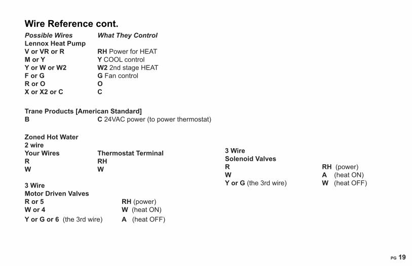
Wire Reference cont. Possible Wires What They Control Lennox Heat Pump V or VR or R RH�Power�for�HEAT�M or Y Y COOL�controlY or W or W2 W2 2nd�stage�HEATF or G G Fan�controlR or O OX or X2 or C C
Trane Products [American Standard]B C�24VAC�power�(to�power�thermostat)�� Zoned Hot Water 2 wireYour Wires Thermostat TerminalR RHW W
3 Wire Motor Driven ValvesR or 5 RH�(power)W or 4 W��(heat�ON)Y or G or 6��(the�3rd�wire)� A���(heat�OFF)
3 Wire Solenoid ValvesR RH �(power)W A ���(heat�ON)Y or G (the�3rd�wire)���� � W ��(heat�OFF)

PG 20
Communicating Thermostat�����The�CT100�has�a�built�in�Z-Wave�radio.�This�allows�
your�thermostat�to�communicate�with�other�systems.
Network INCLUSION 1.��Set�your�primary�controller�to�INCLUDE�mode�to�add�the�thermostat�as�a�node�on�your�network�(see�your�specific�controller’s�User�Manual�for�detailed�instructions.)��2.��Press�and�release�the�MENU�button�on�the�thermostat.��3.��Press�the�MATE�button.�This�will�bring�you�to�the�network�screen�and�a�large�r1�will�be�displayed.�4.��Press�the�MATE�button�again.�This�will�initiate�the�mating�process.��When�a�device�has�joined�a�network�the�word�LINK�will�appear�under�the�radio�tower.Your�controller�will�indicate�the�thermostat�was�successfully�added�to�its�network�(see�your�specific�controller’s�User�Manual�for�details).
Network EXCLUSION 1.��Set�your�primary�controller�to�EXCLUDE�mode�to�remove�the�thermostat�as�a�node�on�your�network�(see�your�specific�controller’s�User�Manual�for�detailed�instructions.)��2.��Press�and�release�the�MENU�button�on�the�thermostat.��3.��Press�the�MATE�button�-�This�will�bring�you�to�the�network�screen�and�a�large�r1�will�be�displayed.�4.��Press�the�MATE�button,�this�will�initiate�the�mating�process.��When�a�device�has�been�removed�
PG 20
PG 21
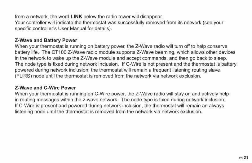
from�a�network,�the�word�LINK below�the�radio�tower�will�disappear.Your�controller�will�indicate�the�thermostat�was�successfully�removed�from�its�network�(see�your�specific�controller’s�User�Manual�for�details).
Z-Wave and Battery Power When�your�thermostat�is�running�on�battery�power,�the�Z-Wave�radio�will�turn�off�to�help�conserve�battery�life.��The�CT100�Z-Wave�radio�module�supports�Z-Wave�beaming,�which�allows�other�devices�in�the�network�to�wake�up�the�Z-Wave�module�and�accept�commands,�and�then�go�back�to�sleep.��The�node�type�is�fixed�during�network�inclusion.��If�C-Wire�is�not�present�and�the�thermostat�is�battery�powered�during�network�inclusion,�the�thermostat�will�remain�a�frequent�listening�routing�slave�(FLiRS)�node�until�the�thermostat�is�removed�from�the�network�via�network�exclusion.
Z-Wave and C-Wire Power When�your�thermostat�is�running�on�C-Wire�power,�the�Z-Wave�radio�will�stay�on�and�actively�help�in�routing�messages�within�the�z-wave�network.��The�node�type�is�fixed�during�network�inclusion.��If�C-Wire�is�present�and�powered�during�network�inclusion,�the�thermostat�will�remain�an�always�listening�node�until�the�thermostat�is�removed�from�the�network�via�network�exclusion.

PG 22
APPENDIX 1 Multi staged HVAC theory of operation for the CT100
Staging for 2 stage normal or heat pump Cool Target Temperature Maintenance in COOL -�If�the�room�temperature�is�within�the�target�temperature�plus�the�DIFF�setting,�the�first�stage�of�cool�will�turn�on.�If�the�target�temperature�is�not�reached�within�(15�minutes),�the�second�stage�of�cooling�will�turn�on�and�join�the�first�stage�to�reach�the�target�temperature.�Target Temperature Recovery in COOL- If�the�room�temperature�is�beyond�the�new�target�temperature�plus�the�DIFF�setting,�the�first�stage�will�turn�on.�Ten�seconds�later,�the�second�stage�will�turn�on�with�the�first�stage�to�help�reach�the�new�target.With�FAST�recovery,�both�stages�stay�on�until�the�new�target�temperature�is�reached.�With�ECON�recovery,�both�stages�stay�on�until�the�DIFF�setting�is�reached.�Then,�the�second�stage�shuts�off�and�the�first�stage�stays�on�to�the�new�target.
Staging for 2 stage normal HeatTarget Temperature Maintenance in HEAT -�If�the�room�temperature�is�within�the�target�temperature�minus�the�DIFF�setting,�the�first�stage�of�heat�will�turn�on.�If�the�target�temperature�is�not�reached�within�(15�minutes),�the�second�stage�of�heat�will�turn�on�and�join�the�first�stage�to�reach�the�target�temperature.�Example:�Target�temperature�70F,�DIFF�at�2F,�maintenance�occurs�at�room�temperatures�of�69F�and�68F.Target Temperature Recovery in HEAT- If�the�room�temperature�is�beyond�the�new�target�temperature�minus�the�DIFF,�the�first�stage�will�turn�on.�Ten�seconds�later,�the�second�stage�will�turn�on�and�join�the�first�stage�to�help�reach�the�target�temperature..�With�FAST�recovery,�both�stages�stay�on�until�the�target�temperature�is�reached.�With�ECON�recovery,�both�stages�stay�on�until�the�DIFF�setting�is�reached.�Then,�the�second�stage�shuts�off�and�the�first�stage�stays�on�until�the�target�temperature�is�reached.
Staging for a 2 stage Heat Pump with no auxiliary heatTarget Temperature Maintenance - If�the�room�temperature�is�within�the�target�temperature�minus�the�DIFF�setting,�the�first�stage�heat�pump�will�turn�on.�If�the�target�temperature�is�not�reached�within�(15�minutes),�the�second�stage�of�heat�pump�will�turn�on�and�join�the�first�stage�to�reach�the�target.�

PG 22
PG 23
Target Temperature Recovery -�If�the�room�temperature�is�beyond�the�new�target�temperature�minus�the�DIFF�setting,�the�first�stage�will�turn�on.�Ten�seconds�later,�the�second�stage�will�turn�on�and�join�the�first�stage�to�reach�the�target�temperature.With�FAST�recovery,�both�stages�stay�on�until�the�new�target�temperature�is�reached.�With�ECON�recovery,�both�stages�stay�on�until�the�DIFF�setting�is�reached.�Then�the�second�stage�shuts�off�and�the�first�stage�stays�on�until�the�new�target�temperature�is�reached.�
Staging for Heat Pump with 1 or 2 stages of compression and 1 or 2 stages of auxiliary heat Target Temperature Maintenance -�If�the�room�temperature�is�within�the�target�temperature�minus�the�DIFF�setting,�the�auxiliary�heat�will�not�be�used,�just�the�heat�pump�(1�or�2�stages)�as�explained�above�in�“target�temperature�maintenance”.
Target Temperature Recovery -�If�the�room�temperature�is�beyond�the�new�target�minus�the�DIFF�setting,�the�first�stage�of�heat�pump�will�turn�on,�ten�seconds�later�the�second�stage�of�heat�pump�will�turn�on,�ten�seconds�later�the�first�stage�of�auxiliary�heat�will�turn�on.�If�the�new�target�temperature�is�then�not�reached�after�15�minutes,�the�second�stage�of�auxiliary�heat�will�turn�on.�With�FAST�recovery�all�stages�will�stay�on�until�the�new�target�temperature�is�reached.�With�ECON�recovery�all�stages�will�stay�on�until�the�DIFF�setting�is�reached.�Then�only�the�heat�pump�stays�on�until�the�new�target�temperature�is�reached.
AUTO EMERGENCY for�cold�climates�instead�of�switching�EMER�on:With�the�DIFF�set�at�2F,�the�swing�at�1F,�and�the�recovery�in�FAST:�if�the�heat�pump�cannot�keep�up�and�the�room�temperature�droops�over�the�DIFF�(2F),�the�AUX�heat�will�come�on�all�the�way�to�the�target.
ELECTRIC vs. GAS or OIL auxiliary heat -�With�electric�auxiliary�heat,�the�heat�pump�stays�on�while�the�auxiliary�heat�is�on.�With�gas�or�oil�auxiliary�heat,�the�heat�pump�will�shut�off�while�the�auxiliary�heat�is�on.��This�is�required�by�heat�pump�design.
Related Documents