PETROLEUM UNIT OPERATION PROCESSES Prepared by : Barhm AB Mohamad M.Tech, Mechanical Engineering

Welcome message from author
This document is posted to help you gain knowledge. Please leave a comment to let me know what you think about it! Share it to your friends and learn new things together.
Transcript
PETROLEUM UNIT OPERATION PROCESSES
Prepared by :
Barhm AB Mohamad
M.Tech, Mechanical Engineering
2
OUTLINE
1. Introduction
2. Physical Processes
3. Thermal Processes
4. Catalytic Processes
5. Conversion of Heavy Residues
6. Treatment of Refinery Gas Streams

3
INTRODUCTION
• Type of crude oil
The American petroleum institute or API gravity, is a measure of how heavy or light a petroleum liquid is compared to water. If its API gravity is greater than 10, it is lighter and floats on water; if less than 10, it is heavier and sinks. API gravity is thus an inverse measure of the relative density of a petroleum liquid and the density of water.
Light heavy
medium

5
Overview
• Type of refineries according to flow process:
Batch flow continuous flow
1. Batch production is a technique used in manufacturing, the feed will treated in one time and then discharged to storage.
2. Continuous production is a flow production method used to manufacture , produce, or process materials without interruption. Continuous production is called a continuous process or a continuous flow process because the materials, either dry bulk or fluids that are being processed are continuously in motion, undergoing chemical reactions or subject to mechanical or heat treatment.
6
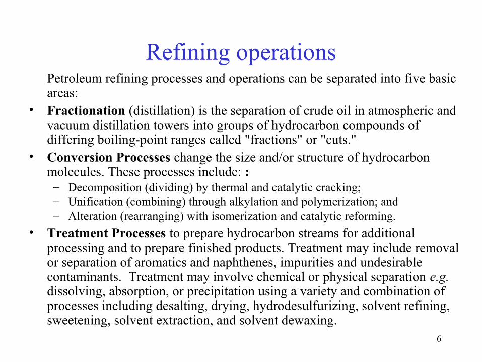
Refining operationsPetroleum refining processes and operations can be separated into five basic areas:
• Fractionation (distillation) is the separation of crude oil in atmospheric and vacuum distillation towers into groups of hydrocarbon compounds of differing boiling-point ranges called "fractions" or "cuts."
• Conversion Processes change the size and/or structure of hydrocarbon molecules. These processes include: :– Decomposition (dividing) by thermal and catalytic cracking; – Unification (combining) through alkylation and polymerization; and– Alteration (rearranging) with isomerization and catalytic reforming.
• Treatment Processes to prepare hydrocarbon streams for additional processing and to prepare finished products. Treatment may include removal or separation of aromatics and naphthenes, impurities and undesirable contaminants. Treatment may involve chemical or physical separation e.g. dissolving, absorption, or precipitation using a variety and combination of processes including desalting, drying, hydrodesulfurizing, solvent refining, sweetening, solvent extraction, and solvent dewaxing.


8
Refining operations
• Formulating and Blending is the process of mixing and combining hydrocarbon fractions, additives, and other components to produce finished products with specific performance properties.
• Other Refining Operations include:– light-ends recovery;– sour-water stripping;– solid waste, process-water and wastewater treatment;– cooling, storage and handling and product movement;– hydrogen production;– acid and tail-gas treatment;– and sulfur recovery.

10
Refining operations
• Auxiliary Operations and Facilities include:– light steam and power generation;– process and fire water systems;– flares and relief systems;– furnaces and heaters;– pumps and valves;– supply of steam, air, nitrogen, and other plant gases;– alarms and sensors;– noise and pollution controls;– sampling, testing, and inspecting and laboratory;– control room;– maintenance; and– administrative facilities.

12
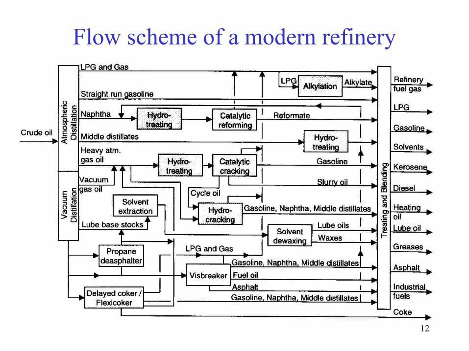
Flow scheme of a modern refinery
13
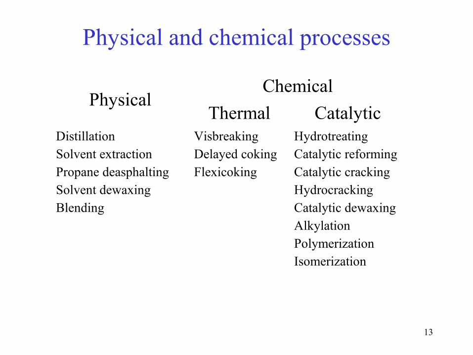
Physical and chemical processes
PhysicalChemical
Thermal CatalyticDistillationSolvent extractionPropane deasphaltingSolvent dewaxingBlending
VisbreakingDelayed cokingFlexicoking
HydrotreatingCatalytic reformingCatalytic crackingHydrocrackingCatalytic dewaxingAlkylationPolymerizationIsomerization

What’s All this Stuff?
16
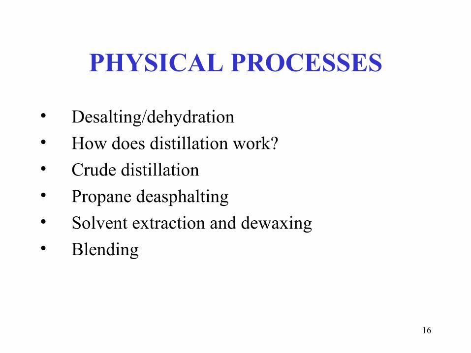
PHYSICAL PROCESSES
• Desalting/dehydration• How does distillation work?• Crude distillation• Propane deasphalting• Solvent extraction and dewaxing• Blending

17
Desalting/dehydration• Crude oil often contains water, inorganic salts, suspended solids, and
water-soluble trace metals.• Step 1 in the refining process is to remove these contaminants so as to
reduce corrosion, plugging, and fouling of equipment and to prevent poisoning catalysts in processing units.
• Step 2 most typical methods of crude-oil desalting are chemical and electrostatic separation, and both use hot water as the extraction agent.
• In chemical desalting, water and chemical surfactant are added to the crude, which is heated so that salts and other impurities dissolve or attach to the water, then held in a tank to settle out.
• Electrical desalting is the application of high-voltage electrostatic charges to concentrate suspended water globules in the bottom of the settling tank. Surfactants are added only when the crude has a large amount of suspended solids.

18
Desalting/dehydration• The crude oil feedstock is heated to 65-180°C to reduce viscosity and
surface tension for easier mixing and separation of the water. The temperature is limited by the vapor pressure of the crude-oil feedstock.
• In both methods other chemicals may be added. Ammonia is often used to reduce corrosion. Caustic or acid may be added to adjust the pH of the water wash.
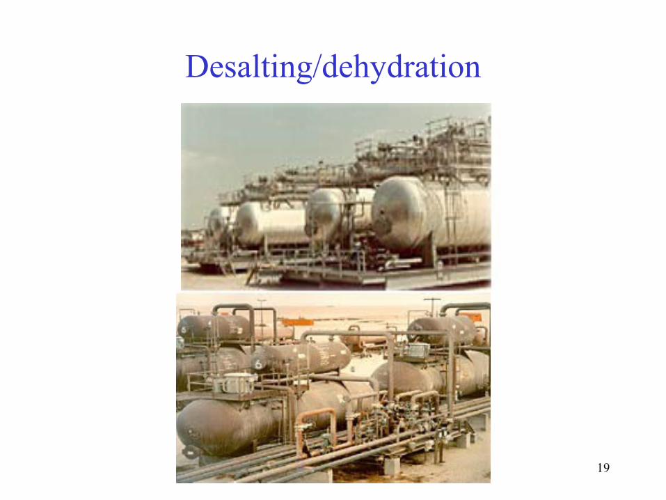
19
Desalting/dehydration
20
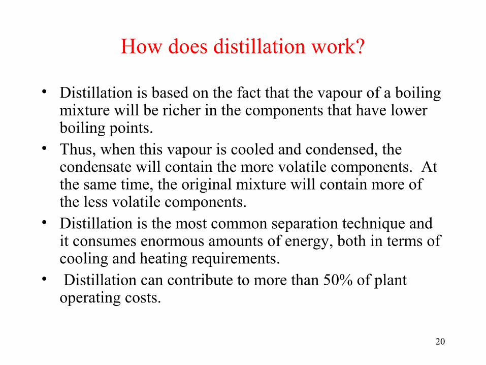
How does distillation work?
• Distillation is based on the fact that the vapour of a boiling mixture will be richer in the components that have lower boiling points.
• Thus, when this vapour is cooled and condensed, the condensate will contain the more volatile components. At the same time, the original mixture will contain more of the less volatile components.
• Distillation is the most common separation technique and it consumes enormous amounts of energy, both in terms of cooling and heating requirements.
• Distillation can contribute to more than 50% of plant operating costs.

21
How does distillation work?
Distillation columns are classified by the manner in which they are operated:
1. Batch, in which the feed to the column is introduced batch-wise. That is, the column is charged with a 'batch' and then the distillation process is carried out. When the desired task is achieved, a next batch of feed is introduced.
2. Continuous columns process a continuous feed stream. No interruptions occur unless there is a problem with the column or surrounding process units. They are capable of handling high throughputs and are the most common of the two types.

22
Main Components of Distillation Columns• A vertical shell where separation
of liquid components is done.• Column internals e.g.trays/plates
and/or packings which are used to enhance component separations.
• A reboiler to provide the necessary vaporization for the distillation process.
• A condenser to cool and condense the vapour leaving the top of the column.
• A reflux drum to hold the condensed vapour from the top of the column so that liquid (reflux) can be recycled back to the column.
23
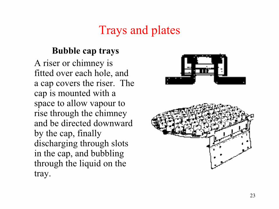
Trays and plates
Bubble cap traysA riser or chimney is fitted over each hole, and a cap covers the riser. The cap is mounted with a space to allow vapour to rise through the chimney and be directed downward by the cap, finally discharging through slots in the cap, and bubbling through the liquid on the tray.
24
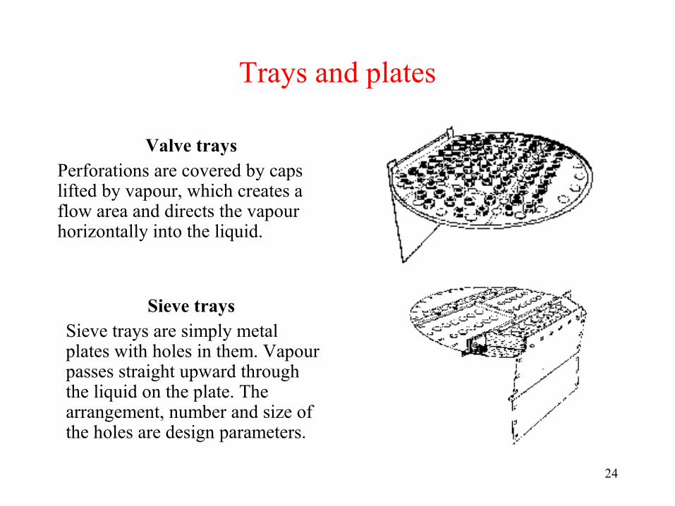
Trays and plates
Valve traysPerforations are covered by caps lifted by vapour, which creates a flow area and directs the vapour horizontally into the liquid.
Sieve traysSieve trays are simply metal plates with holes in them. Vapour passes straight upward through the liquid on the plate. The arrangement, number and size of the holes are design parameters.
25
Liquid and vapour flows in a tray column
26
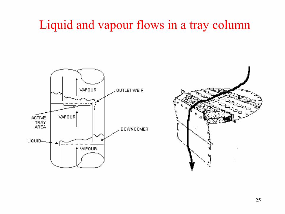
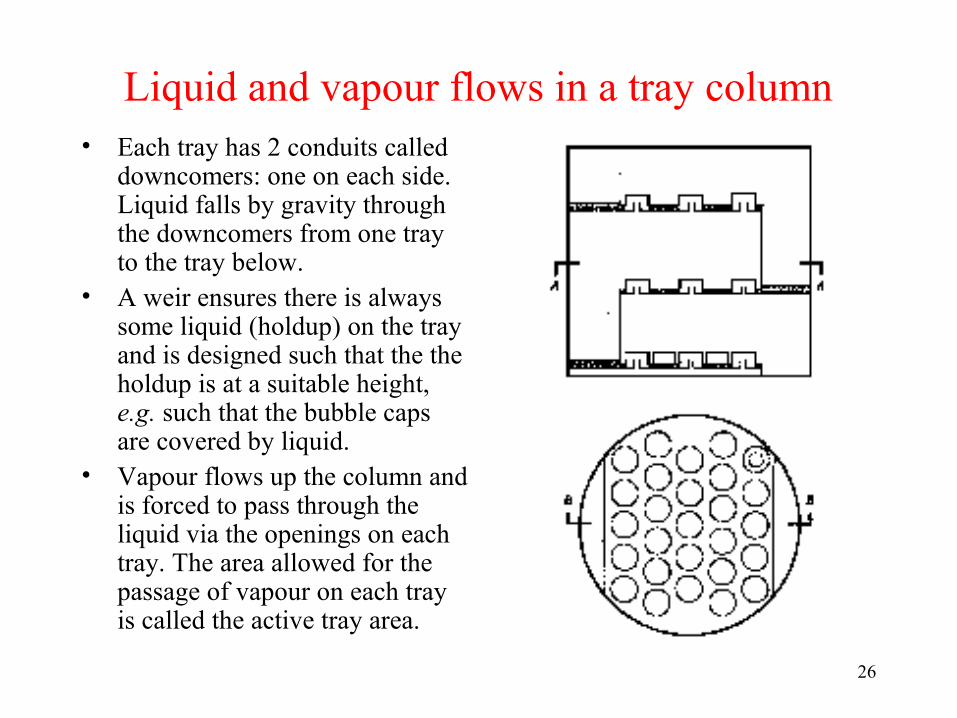
Liquid and vapour flows in a tray column• Each tray has 2 conduits called
downcomers: one on each side. Liquid falls by gravity through the downcomers from one tray to the tray below.
• A weir ensures there is always some liquid (holdup) on the tray and is designed such that the the holdup is at a suitable height, e.g. such that the bubble caps are covered by liquid.
• Vapour flows up the column and is forced to pass through the liquid via the openings on each tray. The area allowed for the passage of vapour on each tray is called the active tray area.

27
Basic operation• The feed is introduced somewhere
near the middle of the column to a tray known as the feed tray.
• The feed tray divides the column into a top (enriching) and a bottom (stripping) section.
• The feed flows down the column where it is collected in the reboiler.
• Heat (usually as steam) is supplied to the reboiler to generate vapour.
• The vapour from the reboiler is re-introduced into the unit at the bottom of the column.
• The liquid removed from the reboiler is known as the bottoms product or simply, bottoms.
28
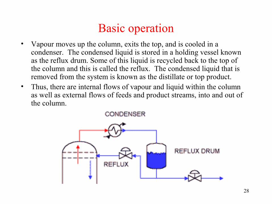
Basic operation• Vapour moves up the column, exits the top, and is cooled in a
condenser. The condensed liquid is stored in a holding vessel known as the reflux drum. Some of this liquid is recycled back to the top of the column and this is called the reflux. The condensed liquid that is removed from the system is known as the distillate or top product.
• Thus, there are internal flows of vapour and liquid within the column as well as external flows of feeds and product streams, into and out of the column.

29
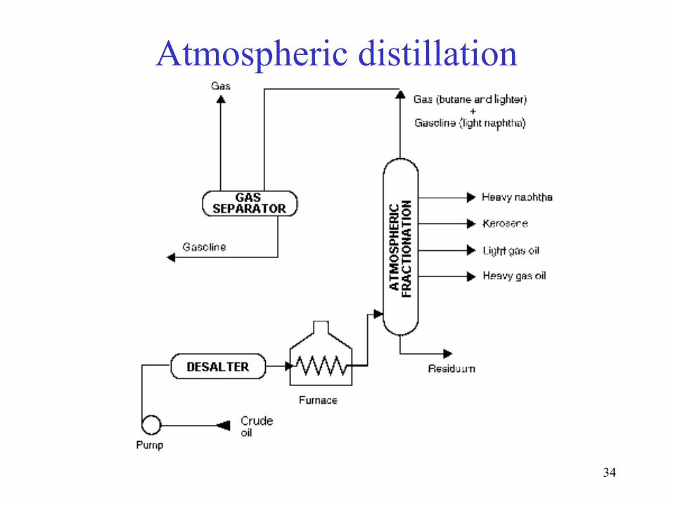
Crude distillation• Step 1 in the refining process is the separation of crude oil into various
fractions or straight-run cuts by distillation in atmospheric and vacuum towers. The main fractions or "cuts" obtained have specific boiling-point ranges and can be classified in order of decreasing volatility into gases, light distillates, middle distillates, gas oils, and residuum.Atmospheric distillation
• The desalted crude feedstock is preheated using recovered process heat. The feedstock then flows to a direct-fired crude charge heater then into the vertical distillation column just above the bottom, at pressures slightly above atmospheric and at temperatures ranging from 300-350°C (above these temperatures undesirable thermal cracking may occur). All but the heaviest fractions flash into vapor.
• As the hot vapor rises in the tower, its temperature is reduced. Heavy fuel oil or asphalt residue is taken from the bottom. At successively higher points on the tower, the various major products including lubricating oil, heating oil, kerosene, gasoline, and uncondensed gases (which condense at lower temperatures) are drawn off.


Other Refinery Units
• Steam Generation• Wastewater Treatment• Hydrogen Generation• Power Generation• Air Separation Plant• Loading/Unloading – Trucks• Storage (high pressure hydrocarbon, crude oil, intermediates)
– Floating-Roof Tanks - 150‘ diameter is common• Self-Contained Firewater Supply• Firewater Pumps

34
Atmospheric distillation
35
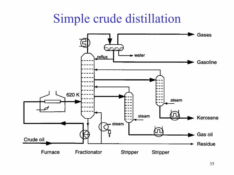
Simple crude distillation

36
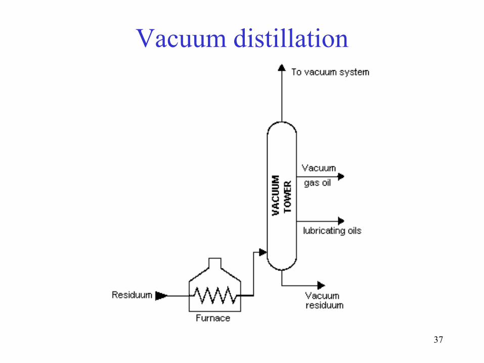
Vacuum distillation• To further distill the residuum or topped crude from the atmospheric
tower without thermal cracking, reduced pressure is required.• The process takes place in one or more vacuum distillation towers.• The principles of vacuum distillation resemble those of fractional
distillation except that larger diameter columns are used to maintain comparable vapor velocities at the reduced pressures. The internal designs of some vacuum towers are different from atmospheric towers in that random packing and demister pads are used instead of trays.
• A typical first-phase vacuum tower may produce gas oils, lubricating-oil base stocks, and heavy residual for propane deasphalting.
• A second-phase tower operating at lower vacuum may distill surplus residuum from the atmospheric tower, which is not used for lube-stock processing, and surplus residuum from the first vacuum tower not used for deasphalting.
• Vacuum towers are typically used to separate catalytic cracking feedstock from surplus residuum.
37
Vacuum distillation
38
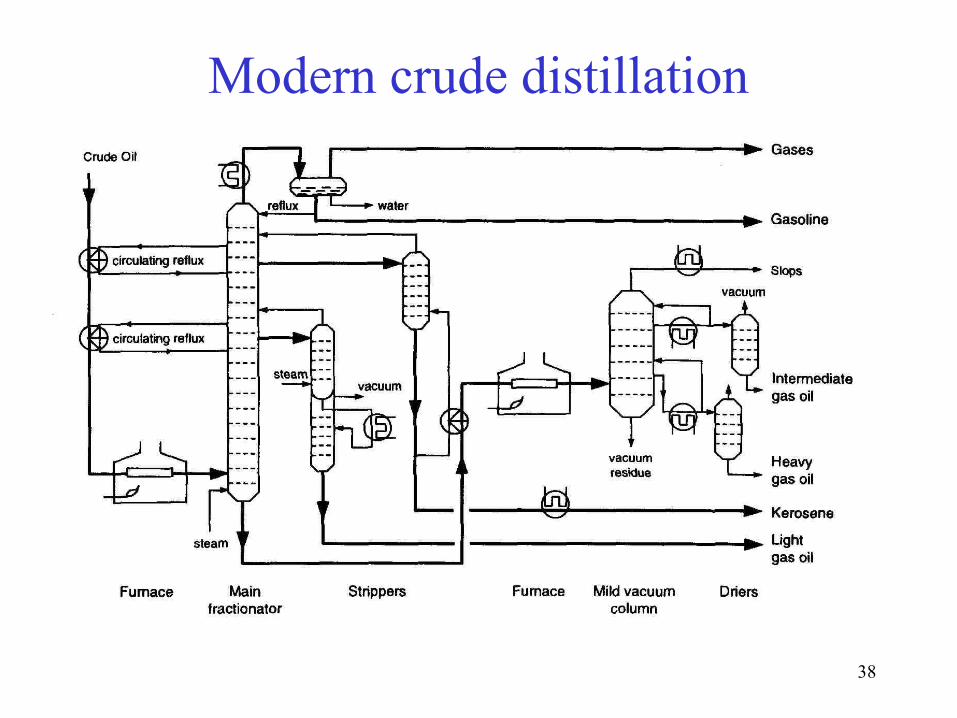
Modern crude distillation

39
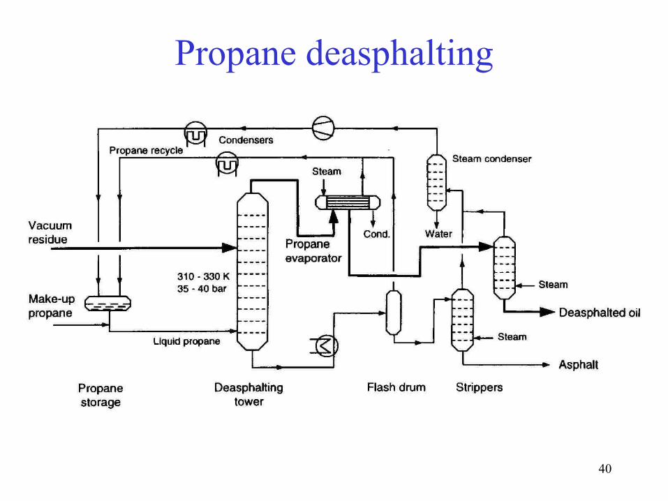
Propane deasphalting• Coke-forming tendencies of heavier distillation products
are reduced by removal of asphaltenic materials by solvent extraction.
• Liquid propane is a good solvent (butane and pentane are also commonly used).
• Deasphalting is based on solubility of hydrocarbons in propane.
• Vacuum residue is fed to a countercurrent deasphalting tower. Alkanes dissolve in propane whereas asphaltenic materials (aromatic compounds), ‘coke-precursors’ do not.
• Asphalt is sent for thermal processing.
40
Propane deasphalting
41
Blending• Blending is the physical mixture of a number of different liquid
hydrocarbons to produce a finished product with certain desired characteristics.
• Products can be blended in-line through a manifold system, or batch blended in tanks and vessels.
• In-line blending of gasoline, distillates, jet fuel, and kerosene is accomplished by injecting proportionate amounts of each component into the main stream where turbulence promotes thorough mixing.
• Additives including octane enhancers, anti-oxidants, anti-knock agents, gum and rust inhibitors, detergents, etc. are added during and/or after blending to provide specific properties not inherent in hydrocarbons.

42
THERMAL PROCESSES
When a hydrocarbon is heated to a sufficiently high temperature thermal cracking occurs. This is sometimes referred to as pyrolysis (especially when coal is the feedstock). When steam is used it is called steam cracking. We will examine two thermal processes used in refineries.
• Visbreaking• Delayed coking
43
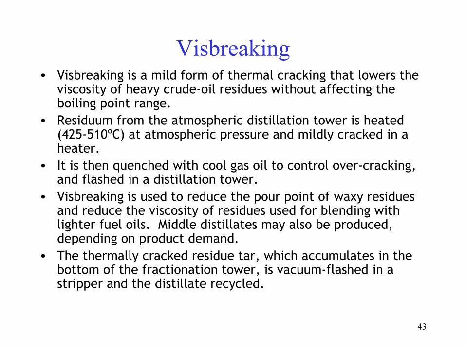
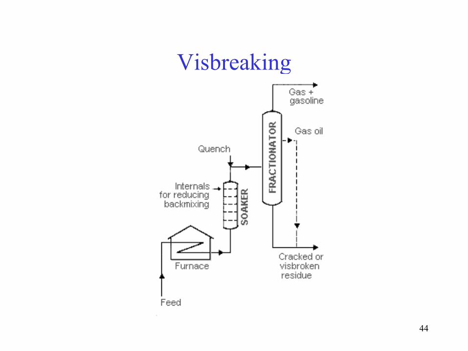
Visbreaking• Visbreaking is a mild form of thermal cracking that lowers the
viscosity of heavy crude-oil residues without affecting the boiling point range.
• Residuum from the atmospheric distillation tower is heated (425-510ºC) at atmospheric pressure and mildly cracked in a heater.
• It is then quenched with cool gas oil to control over-cracking, and flashed in a distillation tower.
• Visbreaking is used to reduce the pour point of waxy residues and reduce the viscosity of residues used for blending with lighter fuel oils. Middle distillates may also be produced, depending on product demand.
• The thermally cracked residue tar, which accumulates in the bottom of the fractionation tower, is vacuum-flashed in a stripper and the distillate recycled.
44
Visbreaking
45
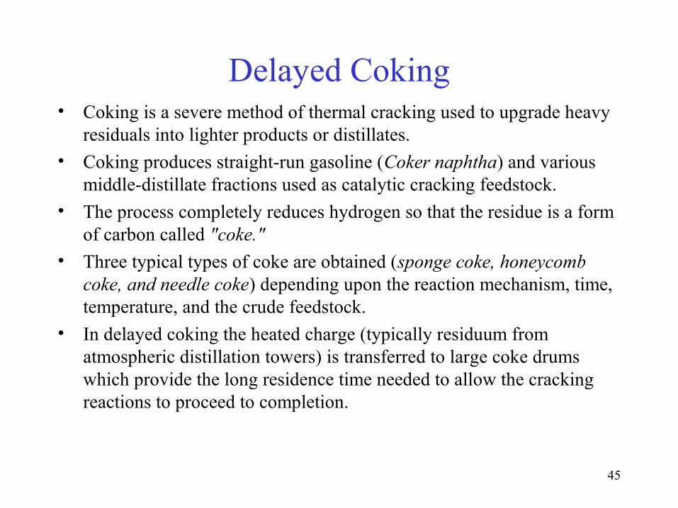
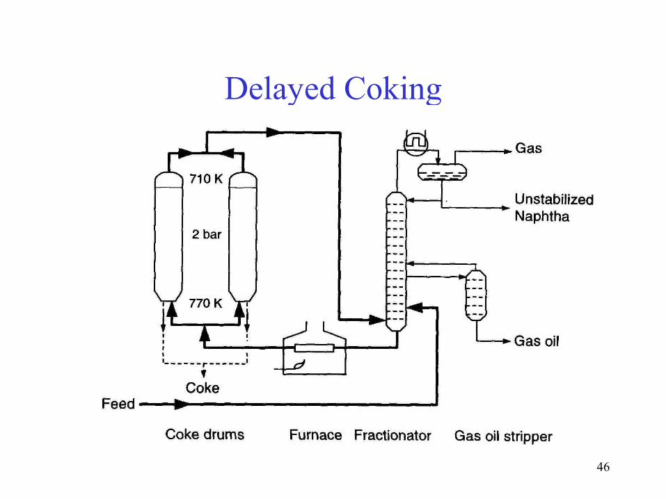
Delayed Coking• Coking is a severe method of thermal cracking used to upgrade heavy
residuals into lighter products or distillates.
• Coking produces straight-run gasoline (Coker naphtha) and various middle-distillate fractions used as catalytic cracking feedstock.
• The process completely reduces hydrogen so that the residue is a form of carbon called "coke."
• Three typical types of coke are obtained (sponge coke, honeycomb coke, and needle coke) depending upon the reaction mechanism, time, temperature, and the crude feedstock.
• In delayed coking the heated charge (typically residuum from atmospheric distillation towers) is transferred to large coke drums which provide the long residence time needed to allow the cracking reactions to proceed to completion.
46
Delayed Coking

47
Fluid Catalytic Cracking• Oil is cracked in the presence of a finely divided catalyst, which is
maintained in an aerated or fluidized state by the oil vapours.• The fluid cracker consists of a catalyst section and a fractionating
section that operate together as an integrated processing unit.• The catalyst section contains the reactor and regenerator, which, with
the standpipe and riser, form the catalyst circulation unit. The fluid catalyst is continuously circulated between the reactor and the regenerator using air, oil vapors, and steam as the conveying media.
• Preheated feed is mixed with hot, regenerated catalyst in the riser and combined with a recycle stream, vapourized, and raised to reactor temperature (485-540°C) by the hot catalyst.
• As the mixture travels up the riser, the charge is cracked at 0.7-2 bar.• In modern FCC units, all cracking takes place in the riser and the
"reactor" merely serves as a holding vessel for the cyclones. Cracked product is then charged to a fractionating column where it is separated into fractions, and some of the heavy oil is recycled to the riser.
48
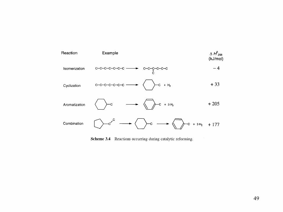
Catalytic Reforming• Catalytic reforming is an important process used to convert low-octane
naphthas into high-octane gasoline blending components called reformates.
• Reforming represents the total effect of numerous reactions such as cracking, polymerization, dehydrogenation, and isomerization taking place simultaneously.
• Depending on the properties of the naphtha feedstock (as measured by the paraffin, olefin, naphthene, and aromatic content) and catalysts used, reformates can be produced with very high concentrations of benzene, toluene, xylene, and other aromatics useful in gasoline blending and petrochemical processing.
• Hydrogen, a significant by-product, is separated from the reformate for recycling and use in other processes.
49
50
Catalytic Reforming• A catalytic reformer comprises a reactor and product-recovery section.
• There is a feed preparation section comprising a combination of hydrotreatment and distillation.
• Most processes use Pt as the active catalyst. Sometimes Pt is combined with a second catalyst (bimetallic catalyst) such as rhenium or another noble metal.
• There are many different commercial processes including platforming, powerforming, ultraforming, and Thermofor catalytic reforming.
• Some reformers operate at low pressure (3-13 bar), others at high pressures (up to 70 bar). Some systems continuously regenerate the catalyst in other systems. One reactor at a time is taken off-stream for catalyst regeneration, and some facilities regenerate all of the reactors during turnarounds.
51
Catalytic Reforming• In the platforming process, the first step is preparation of the naphtha
feed to remove impurities from the naphtha and reduce catalyst degradation.
• The naphtha feedstock is then mixed with hydrogen, vaporized, and passed through a series of alternating furnace and fixed-bed reactors containing a platinum catalyst.
• The effluent from the last reactor is cooled and sent to a separator to permit removal of the hydrogen-rich gas stream from the top of the separator for recycling.
• The liquid product from the bottom of the separator is sent to a fractionator called a stabilizer (butanizer). It makes a bottom product called reformate; butanes and lighter go overhead and are sent to the saturated gas plant.

52
Catalytic reforming scheme

53
Semi-regenerative catalytic reforming
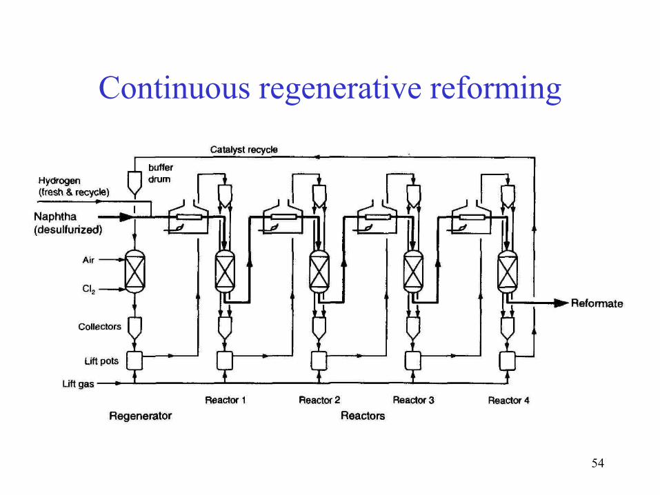
54
Continuous regenerative reforming
55
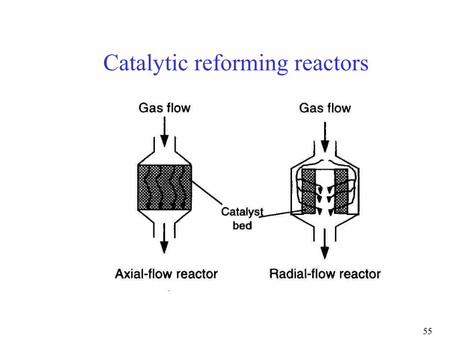
Catalytic reforming reactors
56
Alkylation• Alkylation combines low-molecular-weight olefins (primarily a
mixture of propylene and butylene) with isobutene in the presence of a catalyst, either sulfuric acid or hydrofluoric acid.
• The product is called alkylate and is composed of a mixture of high-octane, branched-chain paraffinic hydrocarbons.
• Alkylate is a premium blending stock because it has exceptional antiknock properties and is clean burning. The octane number of the alkylate depends mainly upon the kind of olefins used and upon operating conditions.
57
TREATMENT OF REFINERY GASES
• Removal of H2S from gases is usually performed by absorption in the liquid phase.
• The concentrated H2S is frequently converted to elemental sulphur by the “Claus” process (partial oxidation of H2S)
• In the Claus process 95-97% of the H2S is converted.
• H2S is often removed with solvents that can be regenerated, usually alkanolamines: e.g. CH2(OH)CH2NH2 MEA (mono-ethanolamine).
• These amines are highly water soluble with low volatility and their interaction with H2S is much faster than with CO2 so that the amount of absorbed CO2 can be limited by selecting appropriate conditions.
58
REFERENCES
1) Nelson, W. L. Petroleum Refinery Engineering, Tata McGraw Hill Publishing Company Limited, 1985.
2) B.K. Bhaskara Rao, “Modern Petroleum Refining Processes” Edn. 5, Oxford & IBH Publishing Company Pvt. Ltd. New Delhi
Some great websites are:
• http://lorien.ncl.ac.uk/ming/distil/distil0.htm
• http://science.howstuffworks.com/oil-refining.htm
Related Documents
![[Petroleum] - UOP Fluid Catalytic Cracking Unit](https://static.cupdf.com/doc/110x72/55cf9b57550346d033a5ade2/petroleum-uop-fluid-catalytic-cracking-unit.jpg)