THIS DOCUMENT IS A DRAFT CIRCULATED FOR COMMENT AND APPROVAL. IT IS THEREFORE SUBJECT TO CHANGE AND MAY NOT BE REFERRED TO AS AN INTERNATIONAL STANDARD UNTIL PUBLISHED AS SUCH. IN ADDITION TO THEIR EVALUATION AS BEING ACCEPTABLE FOR INDUSTRIAL, TECHNOLOGICAL, COMMERCIAL AND USER PURPOSES, DRAFT INTERNATIONAL STANDARDS MAY ON OCCASION HAVE TO BE CONSIDERED IN THE LIGHT OF THEIR POTENTIAL TO BECOME STANDARDS TO WHICH REFERENCE MAY BE MADE IN NATIONAL REGULATIONS. RECIPIENTS OF THIS DRAFT ARE INVITED TO SUBMIT, WITH THEIR COMMENTS, NOTIFICATION OF ANY RELEVANT PATENT RIGHTS OF WHICH THEY ARE AWARE AND TO PROVIDE SUPPORTING DOCUMENTATION. © International Organization for Standardization, 2013 DRAFT INTERNATIONAL STANDARD ISO/DIS 19901-8 ISO/TC 67/SC 7 Secretariat: BSI Voting begins on Voting terminates on 2013-03-21 2013-08-21 INTERNATIONAL ORGANIZATION FOR STANDARDIZATION • МЕЖДУНАРОДНАЯ ОРГАНИЗАЦИЯ ПО СТАНДАРТИЗАЦИИ • ORGANISATION INTERNATIONALE DE NORMALISATION Petroleum and natural gas industries — Specific requirements for offshore structures — Part 8: Marine soil Investigations Industries du pétrole et du gaz naturel — Exigences spécifiques relatives aux structures en mer — Partie 8: Investigations des sols en mer ICS 75.180.10 ISO/CEN PARALLEL PROCESSING This draft has been developed within the International Organization for Standardization (ISO), and processed under the ISO-lead mode of collaboration as defined in the Vienna Agreement. This draft is hereby submitted to the ISO member bodies and to the CEN member bodies for a parallel five-month enquiry. Should this draft be accepted, a final draft, established on the basis of comments received, will be submitted to a parallel two-month approval vote in ISO and formal vote in CEN. To expedite distribution, this document is circulated as received from the committee secretariat. ISO Central Secretariat work of editing and text composition will be undertaken at publication stage. Pour accélérer la distribution, le présent document est distribué tel qu'il est parvenu du secrétariat du comité. Le travail de rédaction et de composition de texte sera effectué au Secrétariat central de l'ISO au stade de publication.

Welcome message from author
This document is posted to help you gain knowledge. Please leave a comment to let me know what you think about it! Share it to your friends and learn new things together.
Transcript

THIS DOCUMENT IS A DRAFT CIRCULATED FOR COMMENT AND APPROVAL. IT IS THEREFORE SUBJECT TO CHANGE AND MAY NOT BE REFERRED TO AS AN INTERNATIONAL STANDARD UNTIL PUBLISHED AS SUCH.
IN ADDITION TO THEIR EVALUATION AS BEING ACCEPTABLE FOR INDUSTRIAL, TECHNOLOGICAL, COMMERCIAL AND USER PURPOSES, DRAFT INTERNATIONAL STANDARDS MAY ON OCCASION HAVE TO BE CONSIDERED IN THE LIGHT OF THEIR POTENTIAL TO BECOME STANDARDS TO WHICH REFERENCE MAY BE MADE IN NATIONAL REGULATIONS.
RECIPIENTS OF THIS DRAFT ARE INVITED TO SUBMIT, WITH THEIR COMMENTS, NOTIFICATION OF ANY RELEVANT PATENT RIGHTS OF WHICH THEY ARE AWARE AND TO PROVIDE SUPPORTING DOCUMENTATION.
© International Organization for Standardization, 2013
DRAFT INTERNATIONAL STANDARD ISO/DIS 19901-8
ISO/TC 67/SC 7 Secretariat: BSI
Voting begins on Voting terminates on 2013-03-21 2013-08-21
INTERNATIONAL ORGANIZATION FOR STANDARDIZATION • МЕЖДУНАРОДНАЯ ОРГАНИЗАЦИЯ ПО СТАНДАРТИЗАЦИИ • ORGANISATION INTERNATIONALE DE NORMALISATION
Petroleum and natural gas industries — Specific requirements for offshore structures — Part 8: Marine soil Investigations
Industries du pétrole et du gaz naturel — Exigences spécifiques relatives aux structures en mer —
Partie 8: Investigations des sols en mer
ICS 75.180.10
ISO/CEN PARALLEL PROCESSING This draft has been developed within the International Organization for Standardization (ISO), and processed under the ISO-lead mode of collaboration as defined in the Vienna Agreement.
This draft is hereby submitted to the ISO member bodies and to the CEN member bodies for a parallel five-month enquiry.
Should this draft be accepted, a final draft, established on the basis of comments received, will be submitted to a parallel two-month approval vote in ISO and formal vote in CEN.
To expedite distribution, this document is circulated as received from the committee secretariat. ISO Central Secretariat work of editing and text composition will be undertaken at publication stage.
Pour accélérer la distribution, le présent document est distribué tel qu'il est parvenu du secrétariat du comité. Le travail de rédaction et de composition de texte sera effectué au Secrétariat central de l'ISO au stade de publication.

ISO/DIS 19901-8
COPYRIGHT PROTECTED DOCUMENT © ISO 2013 All rights reserved. Unless otherwise specified, no part of this publication may be reproduced or utilized otherwise in any form or by any means, electronic or mechanical, including photocopying, or posting on the internet or an intranet, without prior written permission. Permission can be requested from either ISO at the address below or ISO’s member body in the country of the requester.
ISO copyright office Case postale 56 • CH-1211 Geneva 20 Tel. + 41 22 749 01 11 Fax + 41 22 749 09 47 E-mail [email protected] Web www.iso.org
Published in Switzerland
ii © ISO 2013 – All rights reserved

ISO/DIS 19901-8
© ISO 2013 – All rights reserved© ISO 2013 – All rights reserved iii
Contents Page
Foreword ............................................................................................................................................................. v
Introduction ....................................................................................................................................................... vii 1 Scope ...................................................................................................................................................... 1
2 Normative references ............................................................................................................................ 1
3 Terms and definitions ........................................................................................................................... 2
4 Symbols, units and abbreviated terms ............................................................................................... 6 4.1 Symbols .................................................................................................................................................. 6 4.2 Units ........................................................................................................................................................ 7 4.3 Abbreviated terms ................................................................................................................................. 7
5 Objectives, planning and requirements .............................................................................................. 9 5.1 Objectives .............................................................................................................................................. 9 5.2 Planning.................................................................................................................................................. 9 5.3 Scope of work ...................................................................................................................................... 12 5.4 Health, safety and environmental (HSE) requirements for marine operations ............................. 13 5.5 Other requirements ............................................................................................................................. 14
6 Deployment of investigation equipment ........................................................................................... 15 6.1 Deployment modes ............................................................................................................................. 15 6.2 Precision of vertical depth measurements ....................................................................................... 17 6.3 Positioning requirements ................................................................................................................... 18 6.4 Interaction of investigation equipment with the seafloor ............................................................... 18 7 Drilling and logging ............................................................................................................................. 19 7.1 General ................................................................................................................................................. 19 7.2 Project-specific drilling requirements ............................................................................................... 19 7.3 Drilling objectives and selection of drilling equipment and procedures ...................................... 20 7.4 Drilling operations plan ...................................................................................................................... 20 7.5 Recording of drilling parameters ....................................................................................................... 21 7.6 Borehole geophysical logging ........................................................................................................... 21
8 In situ testing ....................................................................................................................................... 21 8.1 General ................................................................................................................................................. 21 8.2 General requirements for the documentation of in situ tests......................................................... 22 8.3 Cone penetration test (CPT/CPTU) .................................................................................................... 22 8.4 Pore pressure dissipation test (PPDT) .............................................................................................. 27 8.5 Ball and T-bar penetration tests ........................................................................................................ 28 8.6 Seismic cone penetration test (SCPT/SCPTU) ................................................................................. 32 8.7 Field vane test ...................................................................................................................................... 34 8.8 Other in situ tests ................................................................................................................................ 38
9 Sampling............................................................................................................................................... 39 9.1 General ................................................................................................................................................. 39 9.2 Purpose of sampling ........................................................................................................................... 39 9.3 Sampling systems ............................................................................................................................... 40 9.4 Selection of sampling tools ................................................................................................................ 40 9.5 Sample recovery considerations ....................................................................................................... 42 9.6 Handling, transport and storage of samples .................................................................................... 43
10 Laboratory testing ............................................................................................................................... 45 10.1 General ................................................................................................................................................. 45 10.2 Presentation of laboratory test results ............................................................................................. 46 10.3 Instrumentation, calibration and data acquisition ........................................................................... 47 10.4 Preparation of soil specimens for testing ......................................................................................... 47 10.5 Evaluation of intact sample quality ................................................................................................... 49

ISO/DIS 19901-8
iv © ISO 2013 – All rights reserved© ISO 2013 – All rights reserved
11 Reporting ............................................................................................................................................. 50 11.1 Definition of reporting requirements ................................................................................................ 50 11.2 Presentation of field operations and measured and derived parameters .................................... 50 11.3 Data interpretation and evaluation of representative geotechnical parameters .......................... 51
Annex A (informative) Objectives, planning and requirements................................................................... 53 A.1 Scope of work ..................................................................................................................................... 53 A.2 Project execution plan and health, safety and environmental (HSE) requirements .................... 55 A.3 Examples of unconventional soils .................................................................................................... 58
Annex B (informative) Deployment of investigation equipment.................................................................. 59 B.1 Deployment systems and precision of vertical depth measurements .......................................... 59 B.2 Minimization of seafloor disturbance effects .................................................................................. 65 B.3 Operations on steep seafloor gradients ........................................................................................... 65 Annex C (informative) Drilling and logging ................................................................................................... 67 C.1 Drilling methods .................................................................................................................................. 67 C.2 Selection of drilling equipment and procedures ............................................................................. 68 C.3 Drilling operations plan ...................................................................................................................... 70 C.4 Shallow gas ......................................................................................................................................... 71 C.5 Borehole geophysical logging .......................................................................................................... 73 Annex D (informative) In situ testing .............................................................................................................. 75 D.1 CPTU/CPT equipment and procedures ............................................................................................ 75 D.2 Documentation of reference readings for CPTU/CPTs ................................................................... 76 D.3 Seismic cone tests (SCPTU/SCPT) ................................................................................................... 80 D.4 Field vane tests (FVT) ......................................................................................................................... 80 D.5 Other in situ tests ............................................................................................................................... 80 Annex E (informative) Sampling ..................................................................................................................... 81 E.1 Selection of sampling tools ............................................................................................................... 81 E.2 Sample handling and storage ............................................................................................................ 88
Annex F (informative) Laboratory testing ...................................................................................................... 91 F.1 General ................................................................................................................................................. 91 F.2 Classification and index tests ........................................................................................................... 91 F.3 One-dimensional consolidation ........................................................................................................ 97 F.4 Consolidated triaxial tests ............................................................................................................... 100 F.5 Direct shear tests .............................................................................................................................. 109 F.6 Resonant column test ...................................................................................................................... 118 F.7 Piezoceramic bender element tests ................................................................................................ 119 F.8 Thixotropy test .................................................................................................................................. 121 F.9 Permeability ....................................................................................................................................... 121 F.10 Heat conductivity test ...................................................................................................................... 122 F.11 Other laboratory tests ...................................................................................................................... 123 F.12 Geological and geochemical tests .................................................................................................. 123 F.13 Rock testing ...................................................................................................................................... 126
Annex G (informative) Reporting .................................................................................................................. 128 G.1 General ............................................................................................................................................... 128 G.2 Field operations and preliminary results ....................................................................................... 129 G.3 Measured and derived geotechnical parameters and final results ............................................. 129 G.4 Data interpretation and evaluation of representative geotechnical parameters ........................ 130
Bibliography ................................................................................................................................................... 133
ISO/DIS 19901-8
© ISO 2013 – All rights reserved© ISO 2013 – All rights reserved v
Foreword
Part 1: Metocean design and operating considerations
Part 2: Seismic design procedures and criteria
Part 3: Topsides structure
Part 4: Geotechnical and foundation design considerations
Part 5: Weight control during engineering and construction
Part 6: Marine operations
Part 7: Stationkeeping systems for floating offshore structures and mobile offshore units
ISO 19900, Petroleum and natural gas industries — General requirements for offshore structures
ISO 19901 (all parts), Petroleum and natural gas industries — Specific requirements for offshore structures
ISO 19902, Petroleum and natural gas industries — Fixed steel offshore structures
ISO 19903, Petroleum and natural gas industries — Fixed concrete offshore structures
ISO 19904-1, Petroleum and natural gas industries — Floating offshore structures — Part 1: Monohulls, semi-submersibles and spars
ISO 19905-1, Petroleum and natural gas industries — Site-specific assessment of mobile offshore units — Part 1: Jack-ups
ISO 19906, Petroleum and natural gas industries — Arctic offshore structures
ISO 13623, Pipeline transportation systems
ISO 13628-1, Design and operation of subsea production systems — Part 1: General requirements and recommendations
ISO/PRF TR 19905-2, Petroleum and natural gas industries — Site-specific assessment of mobile offshore units — Part 2: Jack-ups commentary
ISO/NP 13628-12, Petroleum and natural gas industries - Design and operation of subsea production systems – Part 12: Dynamic production risers
ISO (the International Organization for Standardization) is a worldwide federation of national standards bodies (ISO member bodies). The work of preparing International Standards is normally carried out through ISO technical committees. Each member body interested in a subject for which a technical committee has been established has the right to be represented on that committee. International organizations, governmental and non-governmental, in liaison with ISO, also take part in the work. ISO collaborates closely with the International Electrotechnical Commission (IEC) on all matters of electrotechnical standardization.
International Standards are drafted in accordance with the rules given in the ISO/IEC Directives, Part 2.
The main task of technical committees is to prepare International Standards. Draft International Standards adopted by the technical committees are circulated to the member bodies for voting. Publication as an International Standard requires approval by at least 75 % of the member bodies casting a vote.

ISO/DIS 19901-8
vi © ISO 2013 – All rights reserved© ISO 2013 – All rights reserved
Attention is drawn to the possibility that some of the elements of this document may be the subject of patent rights. ISO shall not be held responsible for identifying any or all such patent rights.
ISO 19901-8 was prepared by Technical Committee ISO/TC 67, Materials, equipment and offshore structures, Subcommittee SC 7, Offshore structures.
This second/third/... edition cancels and replaces the first/second/... edition (), [clause(s) / subclause(s) / table(s) / figure(s) / annex(es)] of which [has / have] been technically revised.
ISO 19901 consists of the following parts, under the general title Petroleum and natural gas industries — Specific requirements for offshore structures:
ISO/DIS 19901-8
© ISO 2013 – All rights reserved© ISO 2013 – All rights reserved vii
Introduction
The series of International Standards applicable to offshore structures, ISO 19900 to ISO 19906, constitutes a common basis covering those aspects that address design requirements and assessments of all offshore structures used by the petroleum and natural gas industries worldwide. Through their application, the intention is to achieve reliability levels appropriate for manned and unmanned offshore structures, whatever the nature or combination of the materials used.
It is important to recognize that structural integrity is a concept comprising models for describing actions, structural analyses, design rules, safety elements, workmanship, quality control procedures and national requirements, all of which are mutually dependent. The modification of one aspect of design in isolation can disturb the balance of reliability inherent in the overall concept of structural integrity. The implications involved in modifications, therefore, need to be considered in relation to the overall reliability of all offshore structural systems.
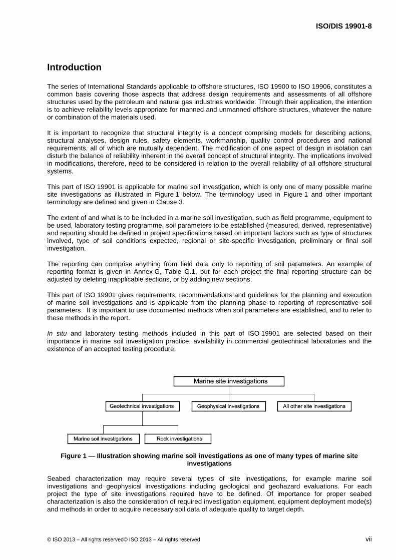
This part of ISO 19901 is applicable for marine soil investigation, which is only one of many possible marine site investigations as illustrated in Figure 1 below. The terminology used in Figure 1 and other important terminology are defined and given in Clause 3.
The extent of and what is to be included in a marine soil investigation, such as field programme, equipment to be used, laboratory testing programme, soil parameters to be established (measured, derived, representative) and reporting should be defined in project specifications based on important factors such as type of structures involved, type of soil conditions expected, regional or site-specific investigation, preliminary or final soil investigation.
The reporting can comprise anything from field data only to reporting of soil parameters. An example of reporting format is given in Annex G, Table G.1, but for each project the final reporting structure can be adjusted by deleting inapplicable sections, or by adding new sections.
This part of ISO 19901 gives requirements, recommendations and guidelines for the planning and execution of marine soil investigations and is applicable from the planning phase to reporting of representative soil parameters. It is important to use documented methods when soil parameters are established, and to refer to these methods in the report.
In situ and laboratory testing methods included in this part of ISO 19901 are selected based on their importance in marine soil investigation practice, availability in commercial geotechnical laboratories and the existence of an accepted testing procedure.
Figure 1 — Illustration showing marine soil investigations as one of many types of marine site investigations
Seabed characterization may require several types of site investigations, for example marine soil investigations and geophysical investigations including geological and geohazard evaluations. For each project the type of site investigations required have to be defined. Of importance for proper seabed characterization is also the consideration of required investigation equipment, equipment deployment mode(s) and methods in order to acquire necessary soil data of adequate quality to target depth.

ISO/DIS 19901-8
viii © ISO 2013 – All rights reserved© ISO 2013 – All rights reserved
This part of ISO 19901 is applicable for marine soil investigations at any water depth and to any depth below seafloor which can be reached with the tools used.
Use of this part of ISO 19901 is based on the assumptions that:
adequate communication takes place between geotechnical personnel involved in marine soil investigations and the personnel responsible for foundation design, construction and installation of the offshore structures;
soil parameters are collected, recorded and interpreted by qualified personnel
project specific scope of work for marine soil investigations is defined by one or more project specifications;
Seabed soils can vary widely, and experience gained at one location is not necessarily applicable at another. The scope of a soil investigation for one type of structure is not necessarily adequate for another. Extra caution is therefore necessary when dealing with unconventional soils or unconventional foundation concepts. Marine soil investigations include both offshore and nearshore soil investigations, which may provide very different challenges.
The detailed requirements for equipment and methods given in this part of ISO 19901 are only applicable if relevant for the scope of work defined in the project specifications.
This part of ISO 19901 is intended to provide flexibility in the choice of soil investigation techniques without hindering innovation.
The primary objectives of this part of ISO 19901 is to provide requirements and guidance for how the most important aspects of a marine soil investigation shall be performed to obtain reliable soil parameters based on documented methods.
In this part of ISO 19901, the following verbal forms are used:
“Shall” and “shall not” are used to indicate requirements strictly to be followed in order to conform to the document and from which no deviation is permitted.
“Should” and “should not” are used to indicate that among several possibilities one is recommended as particularly suitable, without mentioning or excluding others, or that a certain course of action is preferred but not necessarily required, or that (in the negative form) a certain possibility or course of action is deprecated but not prohibited.
“May” and “need not” are used to indicate a course of action permissible within the limits of the document.
“Can” and “cannot” are used for statements of possibility and capability, whether material, physical or causal
This part of ISO 19901 includes informative annexes. Informative annexes give additional information intended to assist the understanding or use of the document. They shall not contain requirements, except that Informative annexes may contain optional requirements (for example a test method that is optional may contain requirements), but there is no need to comply with these requirements to claim compliance with this part of ISO 19901.

DRAFT INTERNATIONAL STANDARD ISO/DIS 19901-8
© ISO 2013 – All rights reserved© ISO 2013 – All rights reserved 1
Petroleum and natural gas industries — Specific requirements for offshore structures — Part 8: Marine soil investigations
1 Scope
This part of ISO 19901 is intended for clients, soil investigation contractors, designers, installation contractors, geotechnical laboratories and public and regulatory authorities concerned with marine soil investigations for any type of offshore and nearshore structures, or geohazard assessment studies, for petroleum and natural gas industries.
This part of ISO 19901 provides requirements, recommendations and guidelines for marine soil investigations regarding:
a) objectives, planning and execution of marine soil investigations;
b) deployment of investigation equipment;
c) drilling and logging;
d) in situ testing;
e) sampling;
f) laboratory testing;
g) reporting.
Rock materials are only covered by this part of ISO 19901 to the extent that ordinary marine soil investigation tools can be used, e.g. for chalk, calcareous soils, cemented soils or similar soft rock. Hard rock investigations are not covered by this part of ISO 19901; see also F.13.
Foundation design is not covered by this part of ISO 19901, but covered in ISO 19901-4 and in the respective design standards for the specific types of offshore structures as listed in the Foreword.
Planning, execution and interpretation of geophysical investigations are not covered by this part of ISO 19901. However, the results from geophysical investigations should, where appropriate, be used for planning, optimization and interpretation of marine soil investigations.
Regarding geohazard assessment studies this part of 19901 does not cover planning, scope and the assessment itself, only the marine soil investigations.
2 Normative references
The following referenced documents are indispensable for the application of this document. For dated references, only the edition cited applies. For undated references, the latest edition of the referenced document (including any amendments) applies.
ISO 19901-4, Petroleum and natural gas industries — Specific requirements for offshore structures — Part 4: Geotechnical and foundation design considerations
ISO 22476-1, 2012-05-31, Geotechnical investigation and testing — Field testing — Part 1: Electrical cone and piezocone penetration tests

ISO/DIS 19901-8
2 © ISO 2013 – All rights reserved© ISO 2013 – All rights reserved
3 Terms and definitions
For the purposes of this document, the following terms and definitions apply.
3.1 accuracy exactness of a measurement compared to the true value of the quantity being measured
3.2 application class classification of equipment types which can achieve different accuracy
Note 1 to entry: Application classes have been developed to give guidance on selection of equipment types, and the selection should be based on required accuracy for use of the results.
Note 2 to entry: In E.1.2 and E.1.3, the terminology “suitability class” is used. However, the intention by giving “suitability classes” is the same as for “application classes”, which is to give guidance on selection of equipment types based on required accuracy for use of the results.
Note 3 to entry: The term “application class” in this part of ISO 19901 is called “quality class” in 3.4.1 of EN 1997-2:2007, and the term “application class” is not used. For the definition of “quality class” in this part of ISO 19901, see 3.22.
3.3 borehole geophysical logging measurement of physical properties of a borehole and/or the surrounding soil, obtained by one or more logging probes deployed in the borehole
3.4 characteristic value value assigned to a basic variable associated with a prescribed probability of not being violated by unfavourable values during some reference period
Note 1 to entry: The characteristic value is the main representative value. In some design situations a variable can have two characteristic values, an upper and a lower value.
3.5 characterization description, evaluation and/or determination of the most typical characteristics based on all types of site investigations and other available data
3.6 client party or person with overall responsibility for the marine soil investigation including preparation of project specifications
3.7 contractor party or person responsible for an assigned scope of work described in project specifications
3.8 derived value value of a geotechnical parameter obtained from test results by theory, correlation or empiricism
3.9 disturbed sample sample whose soil structure, water content and/or constituents have been changed during sampling and handling
ISO/DIS 19901-8
© ISO 2013 – All rights reserved© ISO 2013 – All rights reserved 3
3.10 drained condition condition whereby the applied stresses and stress changes are supported by the soil skeleton and do not cause a change in pore pressure
3.11 drilling mud drilling fluid fluid pumped down a rotary drilled borehole to facilitate the drilling process.
Note 1 to entry: The hardware associated with handling drilling fluids is commonly prefixed ‘mud’ (e.g. mud tank, mud pump, mud valve, etc.). Drilling parameters associated with drilling fluids are similarly prefixed (mud pressure, mud flow etc.).
3.12 geohazard geological state which represents or has the potential to develop further into a situation leading to damage or uncontrolled risk
3.13 geophysical investigation marine site investigation of seafloor or seabed by the use of non destructive methods requiring marine deployment of geophysical tools
See also Figure 1 in Introduction.
3.14 in-pipe logging logging in a section of the borehole or drill pipe between the tool and the borehole wall
Note 1 to entry: The number of parameters that can be usefully measured in these circumstances is restricted.
3.15 intact sample sample that was collected with intention to preserve its in situ characteristics
3.16 marine site investigations any type of investigation at an offshore or nearshore site
See also Figure 1 in Introduction.
EXAMPLE Examples of marine site investigations: Marine soil investigation, geophysical investigation, environmental investigation, metocean investigation.
3.17 marine soil investigation type of marine site investigation with primary objectives to obtain reliable and representative soil data for characterization of the seabed soil conditions for design of offshore structures and/or for geohazard evaluations
See Figure 1 in Introduction.
Note 1 to entry: The scope of work and extent of a marine soil investigation will vary from one project to another, but will usually include one or more of the items listed in Clause 1.
3.18 measured value value that is measured in a test

ISO/DIS 19901-8
4 © ISO 2013 – All rights reserved© ISO 2013 – All rights reserved
3.19 nominal value value assigned to a basic variable determined on a nonstatistical basis, typically from acquired experience or physical conditions
3.20 open-hole logging logging in a section of the borehole without for example casing or drill pipe, allowing a direct measurement of the soil properties outside the borehole wall to be made
3.21 project specification scope of work for marine soil investigations assigned by the client to a contractor
3.22 quality class classification of sample quality for low to medium OCR clays, where the sample quality is based on measured volume change from laboratory consolidation tests
Note 1 to entry: Exact definitions of the various sample quality classes are given in 10.5, Table 6.
Note 2 to entry: The definition of “quality class” given in this part of ISO 19901 differs from the definition of “quality class” given in 3.4.1 of EN 1997-2:2007. What is called “quality class” in EN 1997-2:2007 is called “application class” in this part of ISO 19901, see 3.2. The term “application class” is not used in EN 1997-2:2007.
3.23 rat hole additional depth drilled at the end of the borehole (beyond the last zone of interest) to ensure that the zone of interest can be fully evaluated
Note 1 to entry: The rat hole allows tools at the top of the logging string to reach and measure the deepest zone of interest.
3.24 reconstituted specimen laboratory specimen prepared by reconstituting a thoroughly mixed soil sample
Note 1 to entry: For fine soils, the specimen is prepared as a slurry (at or above the liquid limit) and then consolidated. For coarse soils, it is either poured or pluviated in dry (dried) or wet conditions and compacted, or consolidated.
3.25 remoulded sample remoulded specimen sample of which the soil specimen is thoroughly reworked mechanically at constant water content
3.26 representative value value assigned to a basic variable for verification of a limit state
Note 1 to entry: A representative value may be the characteristic value or an accompanying value. In some design situations a variable can have two representative values, an upper and a lower value.
3.27 sample portion of soil or rock recovered from the seabed soil by sampling techniques
3.28 seabed materials below the seafloor

ISO/DIS 19901-8
© ISO 2013 – All rights reserved© ISO 2013 – All rights reserved 5
3.29 seafloor interface between the sea and the seabed
3.30 settlement permanent downward movement of a structure as a result of its own weight and other actions
Note 1 to entry: Permanent upward movement is called vertical displacement
3.31 site defined investigation area
3.32 soil [geotechnical] parameter measured, derived or representative soil [geotechnical] parameter
Note 1 to entry: The term “geotechnical” includes both soil and rock.
3.33 specimen part of a sample used for a laboratory test
3.34 strength index test test that yields an indication of the shear strength
3.35 swelling expansion due to reduction of effective stress, resulting from either reduction of total stress or absorption of (in general) water at constant total stress
Note 1 to entry: Swelling includes the reverse of both compression and consolidation.
Note 2 to entry: Exsolution of dissolved gas due to stress relief during sampling can cause significant swelling in samples.
3.36 uncertainty reliability of the measurement results due to sources of systematic and random errors
3.37 undisturbed sample sample in which no change of practical significance has occurred in the soil characteristics
3.38 undrained condition condition whereby the applied stresses and stress changes are supported by both the soil skeleton and the pore fluid and do not cause a change in volume
3.39 undrained shear strength maximum shear stress at yielding or at a specified maximum strain in an undrained condition
Note 1 to entry: Yielding is the condition of a material in which a large plastic strain occurs at little or no stress increase.
Note 2 to entry: Strain softening is also to be considered.

ISO/DIS 19901-8
6 © ISO 2013 – All rights reserved© ISO 2013 – All rights reserved
4 Symbols, units and abbreviated terms
4.1 Symbols
a net area ratio of the cone penetrometer
cv coefficient of consolidation
Cs swelling index (for consolidation tests)
hsf height of reference point above seafloor
fs cone sleeve friction
Gmax initial (small strain) shear modulus
IL liquidity index
IP plasticity index
i inclination
Ko coefficient of earth pressure at rest (= σ'h0 /σ'v0)
mv coefficient of compressibility
p0′ in situ vertical effective stress (=σ'v0 )
qc cone penetration resistance
qt cone penetration resistance corrected for pore water pressure effects
s vane blade thickness
su = cu undrained (undisturbed) shear strength of soil
suC static triaxial compression undrained shear strength
suD static DSS undrained shear strength
suE static triaxial extension undrained shear strength
sufv shear strength by vane testing
sufv,rem remoulded shear strength by vane testing
sufv,res residual shear strength by vane testing
St soil sensitivity
u2 pore pressure
Vp compression wave velocity

ISO/DIS 19901-8
© ISO 2013 – All rights reserved© ISO 2013 – All rights reserved 7
Vs shear wave velocity
vvh vertically (v) propagated, horizontally (h) polarized shear wave velocity
ξ material damping ratio
z height above seafloor for drilling mode in situ probe zero reference readings
γ ′ submerged unit weight of soil
γm material factor
ν Poisson's ratio
σ stress
σ'v0 in situ vertical effective stress ( = p0′ )
σ'h0 in situ horizontal effective stress
φ ′ effective angle of internal friction
4.2 Units
Units to be used may vary somewhat from one clause to another based on historical use. For example, a CPT cone cross-sectional area should be given in units of square millimetres (mm2) as used today, and not for example in square metres (m2). However, if there are no special historical reasons for deviating from the units listed below, then the units to be used are:
force kN
moment kNm
density kg/m3
unit weight kN/m3
stress, pressure, strength and stiffness kPa
coefficient of permeability m/s
coefficient of consolidation m2/s
4.3 Abbreviated terms
BHA bottom hole assembly
CCV consolidated constant volume
CD consolidated drained
CPT cone penetration test
CPTU cone penetration test with pore-pressure measurement
CRS controlled rate of strain
CT computerized tomography

ISO/DIS 19901-8
8 © ISO 2013 – All rights reserved© ISO 2013 – All rights reserved
CU consolidated undrained
DS direct shear
DGPS differential global positioning system
DSS direct simple shear
ERP emergency response plan
FVT field vane test
GIS geographical information system
GNSS global navigation satellite system
HAZID hazard identification
HAZOP hazard and operability
HSE health, safety and environment
HVAC heating, ventilation and air conditioning
IL incremental loading
LAT lowest astronomical tide
LBL long baseline
MSL mean sea level
MSCL multi-sensory core logging
OCR over-consolidation ratio
PEP project execution plan
PPE personal protective equipment
QA quality assurance
QC quality control
RFID radio-frequency identification
ROP rate of penetration
ROV remotely operated vehicle
RS ring shear
SCPT seismic CPT
SH shear waves
SHANSEP stress history and normalized soil engineering parameters
SIMOPS simultaneous operations

ISO/DIS 19901-8
© ISO 2013 – All rights reserved© ISO 2013 – All rights reserved 9
SOW scope of work
SRB sulphate-reducing bacteria
SWL safe working load
TC triaxial compression
TE triaxial extension
TOC total organic content
UCT unconfined compression test
USBL ultra-short baseline
UU unconsolidated-undrained
WGS World Geographic System
VSP vertical seismic profiling
YSR yield stress ratio
5 Objectives, planning and requirements
5.1 Objectives
The objectives of marine site investigations are to make relevant and adequate soil data available at the various project phases. In particular, the acquired data is usually required to enable assessment of the site suitability with respect to the offshore structure and the level of acceptable risks for the foundation and integrity of that structure.
NOTE ISO 31000 provides guidance on risk management principles.
The general objectives of a marine soil investigation are to establish the characteristics and mechanical properties of the seabed soils by acquisition, evaluation and presentation of geotechnical information derived from methods relying on tools penetrating into the seabed. The requirements given in ISO 19901-4 for marine soil investigations shall apply. Specific objectives of a marine soil investigation may be given in project specifications.
5.2 Planning
Marine site investigations commonly consist of the following sequence of activities:
a) desk study, including the evaluation of information available in the public domain, available geophysical data, and the results of any previous marine soil investigations in the area;
b) shallow geophysical investigations;
c) marine soil investigations, which may comprise one or more phases to suit the design phases;
d) further integrated study combining the information gathered in the desk study, shallow geophysical investigation and marine soil investigation phases.
Shallow geophysical investigations typically comprise
bathymetry and seafloor topography, using echo-sounding or swathe bathymetry;
seabed features and obstructions, using methods such as side-scan sonar imaging and magnetometry;

ISO/DIS 19901-8
10 © ISO 2013 – All rights reserved© ISO 2013 – All rights reserved
seabed stratigraphy, using methods such as sub-bottom profiling, usually by means of high-resolution reflection seismic.
NOTE 1 Shallow geophysical investigations are not covered by this part of ISO 19901, but the use of the results is important for marine soil investigations.
NOTE 2 ISSMGE (2005) provides guidance on shallow geophysical investigations.
A “limited-scope” marine soil investigation is commonly performed in conjunction with shallow geophysical investigations for the purpose of preliminary ground-truthing of the sub-bottom profiling data. The results of a shallow geophysical investigation, alone or in addition to a desk study, are generally not sufficient for detailed design of an offshore structure.
A shallow geophysical investigation typically covers a large extent of seabed, enabling the identification of localized, non-characteristic seabed features such as:
buried channel or ice gouge features;
erosion features;
slides or shallow mass transport deposits;
gas, gas pockets or potential gas pockets;
specific seafloor features (e.g. pockmarks, concretions, chemo-synthetic communities and seafloor expulsion features, drill cuttings mounds).
A marine soil investigation can include logging, in situ testing and sampling operations, with field and onshore laboratory testing performed on the recovered samples, evaluation of geotechnical data and results and reporting. Specific guidance is given on selection of appropriate equipment and procedures in subsequent clauses of this part of ISO 19901. The date by which appropriate geotechnical information is required determines when a marine soil investigation should be done. Having the marine soil investigation on the critical path can adversely impact subsequent activities, particularly in case of unexpected findings that require additional work.
Considerations for planning a marine soil investigation include project phases, requirements of the offshore structure and risk level.
NOTE Examples of project phases are site selection, conceptual design, preliminary design, detailed design, re-certification, decommissioning. Risk level is commonly expressed by probability of failure and consequences of failure. Design codes commonly rely on implicit or explicit risk levels.
Geotechnical design requirements for the offshore structure depend on several factors that can influence the planning of the scope and extent (spatial area and explored depth) of the marine soil investigation, in particular the following:
design phase, ranging from concept selection to decommissioning;
type of offshore structure and foundation solutions;
type and dimensions of loadings;
related design situations, such as bearing capacity, stability, settlements/displacements, soil-structure interaction, installation/removal aspects etc;
criticality of design situations and the possible need for optimization of design and related geotechnical parameter values;
methods to be adopted for solving/analysing the various design situations;
ISO/DIS 19901-8
© ISO 2013 – All rights reserved© ISO 2013 – All rights reserved 11
geohazards.
Depth coverage may range from a few metres below seafloor for a seabed pipeline to generally 100 m below seafloor. Coverage to 200 m may apply for foundations of specific offshore structures and to possibly 400 m may be necessary for characterizing geohazards such as for example shallow water flow sands.
The following factors are typically considered for planning a marine soil investigation:
the type of offshore structures to be designed and the way in which they will interact with the seabed;
the needs for determination of the area geology and related geohazards;
the results of desk studies, earlier geophysical and marine soil investigations;
the prior knowledge of seabed conditions and local geological variability and geohazards including shallow gas;
other considerations, such as local metocean conditions, existing facilities, unexpected unexploded ordnance, and the possibility of contaminated ground;
interaction of investigation equipment with seafloor, see 6.4 for more details;
regulatory requirements.
Investigation of contaminated ground can require special equipment and procedures.
The variability of the seabed and soil conditions at the site is important for the scope of marine soil investigation. Investigations are usually targeted at locations where variations in seabed and soil conditions are anticipated, if of significance to the development, as well as at locations more typical of the site.
The choice of vessel, equipment and procedures typically includes the following considerations:
operational requirements, including:
project specific HSE (for example, risk of encountering shallow gas),
local metocean conditions,
equipment capability to reach target depth,
grouting or not of boreholes after they have been drilled as part of the marine soil investigations (for example, if the borehole is at the location of a structure it may be desirable to grout it up, whereas in areas with shallow gas it may be preferable to leave the borehole open).
quality requirements including:
accuracy and resolution of control of depth below seafloor,
tolerance of actual locations relative to target locations,
sampling (for example, whether sharp edged thin wall piston sample tubes are desirable),
need for and testing activities suitable for the anticipated soil conditions (for example, full flow penetrometers versus CPTU),
logging,
water depth,

ISO/DIS 19901-8
12 © ISO 2013 – All rights reserved© ISO 2013 – All rights reserved
seafloor slope or unevenness, in terms of deployment of equipment and effects on, for example, depth control.
The planning and the scope of work may be modified during the course of a marine soil investigation, upon review and evaluation of the results from the investigation as they become available.
5.3 Scope of work
5.3.1 Responsibility and development of scope of work
The scope of work and extent of a marine soil investigation shall be given in the project specifications, including any planning activities to be undertaken by the contractor.
The project specifications should consider the possibility of an activity that cannot be completed as intended and should consider an appropriate course of action.
NOTE A project may have more than one project specification.
Regarding marine operations, project specifications shall define responsibility for clarifying site clearance issues and any required mitigation measures. Site clearance issues typically include:
navigation requirements such as minimum stand-off distance from existing facilities;
water depth, seafloor slope and unevenness;
risk of encountering shallow gas, unexploded ordnance and contaminated ground;
site permits, including sample export.
Where the client holds relevant information, this shall be made available to the contractor.
The project specifications should state the objectives of the marine soil investigation.
The project specifications should, if relevant, include foundation details of the offshore structures and the selected design approaches.
Where relevant, the project specifications should refer to methods described in this part of ISO 19901. Any references to methods should be accompanied by method-specific information as applicable. If method-specific information is not contained in the project specification, then the contractor’s practice shall apply. The project specifications may refer to or describe alternative methods not covered by this part of ISO 19901.
The project specifications shall, where applicable, include requirements for:
determination of the extent of logging, sampling and testing, consisting of:
type, number, location and depth of in situ testing locations (see Clause 8),
type, number, distribution, location and depth of sampling locations (see Clause 9),
type and number of offshore and onshore laboratory tests (see Clause 10),
choice of appropriate vessel, equipment and techniques (see Clauses 5 through 10);
reporting including presentation of the results of the marine soil investigation and any associated data interpretation (see Clause 11).

ISO/DIS 19901-8
© ISO 2013 – All rights reserved© ISO 2013 – All rights reserved 13
5.3.2 Default and project specified application classes/methods
The following clauses of this part of ISO 19901 give requirements and information on items that should be specified, which include application classes that are considered to be appropriate in many cases. Application classes should be specified such that the objectives of the marine soil investigation can be met.
Default application classes and default methods that shall be used if otherwise not given in project specifications, are:
depth accuracy; see 6.2.3; default is class Z5;
in situ test accuracy for:
CPT/CPTU; see 8.3.3.1; default is class 3,
vane test; see 8.7.3; default is class 2.
When assessing the required accuracy, consideration should be given as to whether relative accuracy or absolute accuracy is required, and the level of variability of the quantity being specified. For example, when specifying depth accuracy, relative accuracy can be more important than absolute accuracy. Knowledge of the thickness of a soil unit can be required to be known to a greater degree of accuracy than its absolute depth. In addition, it should be considered that the depth and thickness of a soil unit can vary across a site and therefore determining its depth at a given location to a high degree of accuracy may not be necessary if the variability of depth between locations is substantially greater or unknown.
If any requirements are not specified in the project specifications, or not given as default values in this standard, then the contractor’s usual practice shall apply.
5.4 Health, safety and environmental (HSE) requirements for marine operations
The marine soil investigation shall comply with governmental, local legislative authority and project HSE requirements. Marine operations should be conducted in accordance with a project HSE plan. The project HSE plan can be part of a project execution plan, see Annex A.
ISO 19901-6 should be considered for marine operations from a vessel used for marine soil investigations. The vessel shall have a Health, Safety and Environment Management System (HSEMS), and the HSEMS should comply with the requirements of the International Management Codes for Safe Operation of Ships (ISM code) and for Pollution Prevention (MARPOL code), and with the Safety of Life at Sea (SOLAS) code, or equivalent codes. The vessel should also comply with the International Ship and Port Facility Security (ISPS) code, where applicable.
The vessel should be crewed/staffed with a sufficient number of qualified, trained, and experienced personnel to perform required marine soil investigation operations, including the operation, maintenance and repair of critical equipment.
The safety and well-being of those involved in, and impacted by, the marine soil investigation shall be considered. All persons shall be familiar with safety procedures requisite for the safe completion of tasks in which they participate [Job Safety Analysis (JSA)] and general onboard safety. The operators of marine soil investigation equipment shall have proper training and experience in the use of the equipment. All persons shall be aware of proper reporting requirements for HSE incidents.
The investigation vessel shall have appropriate safety equipment to comply with SOLAS codes or equivalent codes, including adequate maritime lifesaving equipment, and personal protective equipment (e.g. hard hats, safety glasses, floatation work vests, safety lines) as required by individual JSAs and vessel HSEMS, and shall have onboard personnel familiar with and trained in its use.
Special care should be exercised for “specially-mobilized” vessels, as opposed to purpose-built vessels, for marine soil investigation, to ensure all temporarily-mobilized equipment is safely installed and operated, and that interfaces between permanent vessel crew, who may be unfamiliar with marine soil investigation operations, and temporary crew members (e.g. positioning crew, client representative(s) and any other specialist crew members) are properly managed.
ISO/DIS 19901-8
14 © ISO 2013 – All rights reserved© ISO 2013 – All rights reserved
Marine soil investigation equipment shall not be used before it is safely installed. Lifting equipment, such as cranes, booms, hoists, spreader bars, slings, etc., shall be suitable for the proposed use, checked/inspected/ certified and appropriately tagged/marked. During the marine soil investigation, the vessel should be subject to ongoing safety monitoring.
When operations become unsafe for any reason, such as excessive vessel motion, work shall cease and equipment shall be secured.
Attention shall be paid to the impact of marine soil investigation equipment on HSE. Special substances such as drilling mud, laboratory chemicals and radioactive sources can require special care during handling and storage. The presence and special handling and storage requirements of any hazardous material on board the vessel should be documented in a project-specific safety plan.
A project specific HSE plan should consider the potential impact of in-water investigation equipment on the marine environment (e.g. loss of hydraulic fluid, acoustic noise, etc.).
5.5 Other requirements
5.5.1 Operational requirements
The environmental conditions at the planned fieldwork site, such as water depth, seafloor slope, wave and current conditions, the risk of shallow gas/hydrates and the proposed scope of the marine soil investigation, shall be considered when selecting vessels and investigation tools. Responsibility for undertaking this shall be defined in the project specifications. The primary concern when considering the size and class of a vessel is the safety of the operations and personnel during the work.
Lifting, handling and deployment facilities (A-frames, booms, davits, cables, cradles, drilling equipment, winches, etc.) for the required logging, sampling and in situ testing equipment, supplies and other equipment shall be safe and certified. The additional frictional and suction components imposed on a piece of investigation equipment (e.g. seafloor frame, corer, CPTU) shall be considered when determining the maximum anticipated load on a lifting element as these additional loads can be significant.
Equipment used during the marine soil investigation should have documentation consisting of operational and maintenance procedures. Where two or more pieces of equipment have a critical interface, those interfaces shall be evaluated to ensure proper operation.
Vessel positioning and equipment positioning requirements shall be defined in the project specifications. Further guidance is provided in 6.3.
5.5.2 Quality requirements
Experienced geotechnical practitioners shall be involved during the planning and preparation of the soil investigation scope and project specifications. The fieldwork shall be executed by suitably experienced personnel.
The client should have an appropriate project quality management system in place with quality control to be exercised consistently and competently in all phases of investigation and evaluation. The contractor should operate a documented quality management system based on the ISO 9000 series of International Standards.
A project quality plan should be incorporated as part of a project execution plan (PEP) for the marine soil investigation (see Annex A). This should detail the organizational responsibilities, activities, and an index of referenced and applicable procedures to complete the scope of the marine soil investigation.
Quality system audits against the quality management system should be performed. The client and contractor should address and resolve audit reports, recommendations and/or corrective actions within the responsibility of the client and contractor respectively.

ISO/DIS 19901-8
© ISO 2013 – All rights reserved© ISO 2013 – All rights reserved 15
5.5.3 Specific requirements for unconventional soils
The requirements and recommendations in this part of ISO 19901 have been developed primarily for use in conventional soils, i.e. siliceous sands and clays of terrigenous origins which have relatively well understood generic properties, and for which there are well established global marine soil investigation practices. When performing a marine soil investigation in frontier areas, or areas known or suspected to contain unconventional soils, this may require special handling or treatment for soils such as:
more regional siliceous terrigenous soils (e.g. glacial tills, frozen soils etc);
unusual terrigenous soils (e.g. volcanic ash, silts, glauconitic soils, micaceous soils etc);
non-terrrigenous soils (e.g. carbonate soils - see Note below, calcareous soils, siliceous oozes etc).
The equipment, methods and procedures may also need to be tailored to investigate characteristic properties that may pose particular difficulties for geohazard assessments and engineering. Examples of soils with specific generic properties that may need special attention are listed in Table A.3.
NOTE Carbonate deposits offer an example of how an investigation may need to be adapted to suit soil type: such soils can be variably cemented and range from lightly cemented with sometimes significant void spaces to extremely well cemented. This is particularly the case for sands and silts that contain more than 15 % to 20 % carbonate material. Therefore, in planning a marine soil investigation, it is important to incorporate sufficient flexibility in the scope of work to switch between soil sampling, rock coring, and in situ testing techniques as appropriate. In these soils, a carefully developed field and laboratory testing programme can be warranted. ISO 19901-4 includes guidance.
General guidance on types of unconventional soils and soils with generic properties that have potential difficulties associated with them is given in A.3.
6 Deployment of investigation equipment
6.1 Deployment modes
6.1.1 General
Marine soil investigation equipment can be deployed in a variety of ways. The elected deployment method can influence the quality and the depth to which data can be acquired. The end user of the geotechnical data should ensure that the selected equipment is capable of providing suitably accurate and sufficient geotechnical data for the intended purpose.
6.1.2 Non-drilling mode
Non-drilling mode encompasses the practice by which geotechnical testing or sampling tools are initiated at the seafloor and penetrated in a single stroke to refusal depth or to a predetermined depth. Tool penetrations generally vary from 0,5 m to greater than 25 m below seafloor, depending on the tool that is deployed and the geology that is encountered. Penetrations in excess of 40 m are possible using specialist equipment within very soft seabed.
A vast array of geotechnical testing and sampling equipment is deployed using this technique. The more sophisticated of these tools are landed on the seafloor prior to the commencement of the seabed penetration. The simplest of these tools are simply lowered until they encounter the seafloor, allowed to penetrate to refusal under their own weight, then extracted and recovered to the vessel deck.
The quality of data acquired varies with the level of sophistication of the tools. Sophisticated seafloor-founded, non-drilling mode rigs can acquire high quality samples or in situ data. At the other end of the spectrum, non-heave-compensated winch-controlled tools such as gravity corers, Kullenberg piston corers and vibro corers can have a limited capacity to acquire high quality samples.
A common limitation of non-drilling mode equipment relates to their inability to achieve a target penetration depth when a seabed layer is intercepted whose strength exceeds the penetration capabilities of the tool.

ISO/DIS 19901-8
16 © ISO 2013 – All rights reserved© ISO 2013 – All rights reserved
Notwithstanding the above, non-drilling mode tools are widely used for acquiring seabed geotechnical data in favourable geological conditions, due to their generally high level of availability, comparatively lower cost, and their capacity to be deployed from a wide range of vessels.
6.1.3 Drilling mode
6.1.3.1 General
In drilling mode, logging, sampling and in situ test tools are deployed into the seabed, initially commencing from the seafloor and thereafter from the bottom of a borehole that is progressed via rotary drilling.
Drilling mode operations can be undertaken either from the sea surface, (referred to as ‘vessel drilling’), or alternatively using remotely controlled, seafloor-founded drill rigs (referred to as ‘seafloor drilling’).
Geotechnical tools are deployed to the bottom of the borehole using a variety of techniques, including wireline, free fall, or via advancement and recovery of the drill string itself. Once located at the bottom of the borehole, the geotechnical tool is penetrated via electrical, hydraulic or mechanical means until the maximum stroke length, the borehole target depth, or the mechanical capacity of the system is achieved.
At the completion of a testing or sampling interval, the tool is either recovered to the surface through the drill string (vessel drilling), or temporarily stored on the rig (seafloor drilling). The borehole is then progressed to the next testing or sampling depth.
Further guidance related to rotary drilling techniques is provided in Clause 7.
6.1.3.2 Vessel drilling
Vessel drilling operations are undertaken from either:
a) a spudded, anchored or dynamically positioned floating vessel, such as a drill ship, semi-submersible vessel, barge or similar craft, or
b) a stable platform, such as a jack-up or permanent seabed structure.
Vessel drilling systems are influenced by movements associated with surface environmental conditions. For many vessel drilling systems, the vertical stability of the drill string may be controlled or limited by means of:
a seafloor-founded template with a ‘hard tie system’ heave compensator, ref. Zuidberg et al 1986, or
a heave compensator on the drilling vessel in conjunction with soil resistance that prevents movement of the drill string.
Less sophisticated vessel drilling systems are uncompensated against vessel heave. Further discussion of the effects of vessel heave on drill string stability, and the precision of borehole depth measurements, is provided in B.1.
6.1.3.3 Seafloor drilling
Seafloor drilling systems are either landed on the seafloor and a catenary is formed with the control umbilical, or alternately a constant tension winch is used to isolate the rig from vessel movements. All operations are then undertaken via remote control.
The stability of seafloor drilling systems is largely dependent on the capabilities of the footings used to support the rig. Sophisticated footings systems may incorporate the capacity to self level the rig, and monitor the vertical height of the rig relative to the seafloor to enhance the precision of borehole depth measurements. Less sophisticated rigs may lack the capacity to land and stay reliably at the seafloor, leading to uncontrolled penetration on landing, an increased potential for tilting, and poor estimation of actual borehole depth.
ISO/DIS 19901-8
© ISO 2013 – All rights reserved© ISO 2013 – All rights reserved 17
The action of initially landing equipment on the seafloor can disturb the natural characteristics of the upper seabed. This issue is discussed further in B.2.
6.2 Precision of vertical depth measurements
6.2.1 General
The precision of vertical depth measurements is a critical component of a marine soil investigation. Precise measurement of vertical depth assists in ensuring, for example:
that variations in seabed stratigraphy are accurately defined;
that appropriate overburden and pore water pressure corrections are applied to in situ test data;
that adjacent samples and in situ test data are able to be precisely correlated; and
that appropriate confining stresses are specified during the course of subsequent laboratory test programmes.
6.2.2 Factors affecting the precision of vertical depth measurements
A data point can be defined as any discrete location within a borehole. The depth precision of a data point will vary depending on the mode of equipment deployment, the availability of measuring systems to estimate the location of the tool point relative to the seabed, and the type of tool deployed.
For example, the achievable depth accuracy when using a vessel-mounted drilling system can be dependent on the prevailing environmental conditions at the sea surface, the associated vessel motions, the water depth, the capability of a vessel’s heave-compensation system, and whether the drill string can be stabilized at the seafloor during downhole data acquisition. In contrast, the depth accuracy achieved with a seafloor-founded system can be dependent on the capabilities of the monitoring system used to estimate the position and levelness of the rig relative to the seafloor, and the length of the drill string or push rods deployed downhole.
Data point depth accuracy can additionally vary as a result of the performance of a sampling tool. For example, the allocation of sample loss within a sampling run is often solely based on engineering judgement. This can introduce additional uncertainty as to the actual depth from which the sample originated.
Further discussion on the factors affecting the precision of vertical depth measurements is provided B.1.
6.2.3 Specification of depth accuracy classes
The project specifications should include the class of depth accuracy to be achieved in a marine soil investigation based on the intended use of the geotechnical data, with due consideration of the capabilities of the equipment under consideration. Different degrees of depth accuracy may be specified for in situ testing and sampling operations.
Documentation demonstrating the depth accuracy that can be achieved with proposed investigation equipment should be provided by the geotechnical contractor(s). For cases where depth accuracy is expected to vary with changes in water depth and/or borehole depth below seafloor, the variation in accuracy class should be estimated for each intended investigation area.
Depth accuracy classes are presented in Table 1. Information on the factors affecting depth accuracy for different equipment types, and key parameters for consideration in calculations, are included in Annex B.

ISO/DIS 19901-8
18 © ISO 2013 – All rights reserved© ISO 2013 – All rights reserved
Table 1 — Depth accuracy classes for data point measurements below seafloor
Depth accuracy class Maximum data point depth uncertainty
m
Z1 0,1
Z2 0,5
Z3 1,0
Z4 2,0
Z5 >2,0
A default value, Z5, shall apply for the case where depth accuracy is not given in project specifications.
6.3 Positioning requirements
The requirements regarding horizontal vessel and equipment positioning accuracy shall be given in the project specifications (as noted also in 5.5.1).
The accuracy to which boreholes and/or equipment are located on the seafloor is an important aspect of a geotechnical dataset to ensure that:
current investigation locations are aligned with previous and future soil investigations, and the installation of facilities;
known seafloor hazards, including installed facilities, natural seabed obstructions, excessive gradients, identified areas of shallow gas and other features are avoided with confidence.
The geodetic system, positioning datum and other corrections to be applied to the data set must be specified, and minimum acceptable calibration and integrity testing exercises are to be completed prior to the commencement of an investigation.
Specification of horizontal positioning tolerances may be influenced by:
the type of facilities to be installed on the seafloor;
the type, accuracy capabilities & levels of equipment redundancy of the positioning equipment;
the proximity of existing facilities (including the estimated accuracy of their actual positions);
the known seabed topography: water depth, seafloor slopes, natural features.
For further guidance on horizontal positioning requirements, reference is made to the IHO standards, and OGP-IMCA 2010.
6.4 Interaction of investigation equipment with the seafloor
Most sophisticated marine soil investigation equipment interacts with the upper seabed prior to commencement of data acquisition.
The action of landing equipment on the seafloor can disturb and apply elevated surcharge pressures to the upper seabed, which can be detrimental to data quality. The expected interaction of investigation equipment with the seafloor should be clarified prior to the commencement of a soil investigation.

ISO/DIS 19901-8
© ISO 2013 – All rights reserved© ISO 2013 – All rights reserved 19
Operation of investigation equipment on high seafloor gradients can be impeded. Detailed bathymetry information is normally required to confirm that the investigation equipment can be safely operated in such environments.
Further guidance related to disturbance of the seabed, and operation of equipment on steep seafloor gradients is provided in B.2.2 and B.3, respectively.
7 Drilling and logging
7.1 General
Drilling operations can be undertaken either from the sea surface (‘vessel drilling’) or alternatively using remotely controlled, seafloor-founded drill rigs (‘seafloor drilling’). The various modes of equipment deployment are defined within Clause 6, which also describes the particular aspects that relate to rotary drilling and the subsequent logging of a borehole (if applicable).
In both drilling system deployment modes outlined above, a borehole is advanced by the combined action of a rotating cutting surface (the drill bit) on material at the bottom of the hole and the flow of drilling fluids that flushes drill cuttings in suspension from the bottom of the hole up the enclosing annulus between the drill pipe and borehole wall (or casing inner wall).
Some soil disturbance ahead of the drill bit is inevitable and can have a measurable effect on data quality. Excessive, or varying, weight on the drill bit will tend to increase soil disturbance as the bit impacts virgin material at the drill face. Excessive drilling fluid pressure can induce hydraulic fracture or erosion of virgin material. Excessive drilling-fluid flow can soften or erode virgin material. Soil disturbance can often be assessed by inspection of the results from the sampling and in situ testing. The depth of soil disturbance below the drill face, and the magnitude of its effect, tend to be greater for softer soils.
For marine drilling operations, the vertical stability of the drill string during borehole advancement is critical to the recovery of high quality geotechnical data. Fluctuations in applied bit weight, and associated displacements, during sampling and in situ testing operations can be very detrimental to data quality. Drill string stability is largely affected by the type of equipment used to deploy the drill string. Further information on this issue is provided in Clause 6.
The efficient delivery of the drilling operation can be fundamental to the overall success of the marine soil investigation. Clause 7 and Annex C describe the process for selection and adoption of the most appropriate drilling equipment and procedures for the work, based on project-specific requirements and drilling objectives.
7.2 Project-specific drilling requirements
The choice of drilling equipment suitable for a particular soil investigation is generally dictated by a number of key project-specific drilling requirements, which may consist of:
expected soil conditions and possible drilling hazards, such as shallow gas, flowing sands, swelling clays, hydraulic fracture potential;
required borehole depth and purpose of geotechnical borehole(s), i.e.
1) borehole suitable for deployment of specific testing or sampling tools, and/or
2) borehole to acquire drilling parameters (i.e. destructive drilling);
site environment and seafloor characteristics, e.g. water depth, expected weather and sea conditions (current, tide, extremes of temperature), proximity of surface/submerged/seafloor/buried infrastructure, seafloor topography, natural seafloor features;
allowable uncertainty in borehole depth measurements (see 6.2);
HSE considerations, e.g. manned interventions on the drill floor, environmental discharge regulations for drill cuttings, etc.;

ISO/DIS 19901-8
20 © ISO 2013 – All rights reserved© ISO 2013 – All rights reserved
logistical considerations, e.g. project schedule, availability of equipment.
7.3 Drilling objectives and selection of drilling equipment and procedures
Drilling objectives of the soil investigation are typically one or more of the following:
To recover data of optimal quality, with minimal soil disturbance from drilling, where the soil investigation results will be used to determine geotechnical parameters for design purposes.
To maximize the continuity of data recovered within a borehole (at the possible expense of reduced data quality), for example for geological investigations for which key horizons can be very thin and therefore require a data record as continuous as possible.
To maximize the speed of drilling, at the expense of data quality and/or continuity, in the interests of providing as much spatial or depth coverage of a site as possible within a given time or budget constraint, for example for hard-layer detection, or pilot-hole drilling (for detection of shallow gas).
To minimize the potential for a shallow gas incident. The rapid extraction of wireline tools from the seabed (swabbing effect) can induce a shallow gas ‘kick’. It may also be necessary to perform a pilot-hole for the detection of shallow gas, thereby de-risking further drilling operations.
The drilling equipment and procedures shall be based on the identified drilling objectives, with due consideration of the range of expected soil conditions and drilling hazards that may be encountered. For rotary core drilling, the system and the associated sampling techniques may follow the requirements of ISO 22475-1 (mainly for onshore and nearshore soil investigations).
Further guidance on the selection of drilling equipment and procedures is given in Annex C.
7.4 Drilling operations plan
A separate drilling operations plan (see Annex C) or the project execution plan for the soil investigation (see Annex A) shall cover the proposed drilling operations and shall describe the predicted sequence of activities and contingencies, from initiation to completion of each geotechnical borehole, and include details of the required sampling/testing/logging programme.
The purpose of the drilling operations plan is twofold:
a) during the pre-fieldwork phase, to provide assurance that:
all required information is in place,
the proposed solution is capable of meeting all of the project objectives,
due consideration has been paid to potential drilling hazards, and
contingency plans are in place in the event of foreseeable drilling-related problems;
b) during the fieldwork phase, to control the execution of the drilling and borehole works.
The level of detail required depends on the complexity of the soil investigation, on the tools and techniques to be employed, and on whether any new or modified equipment or procedures are required.
Some areas where marine soil investigations are carried out pose a potential risk of encountering shallow gas, either natural or released from a nearby hydrocarbon extraction/ processing infrastructure. Where the potential for a gas release exists, a shallow gas plan shall be developed. Part of this plan may include the drilling of a separate pilot hole; prior to any geotechnical sampling or in situ testing.

ISO/DIS 19901-8
© ISO 2013 – All rights reserved© ISO 2013 – All rights reserved 21
Guidance for the content of the drilling operations plan and for the performance of shallow gas risk assessment is provided in Annex C.
7.5 Recording of drilling parameters
During the process of borehole drilling the system operational and performance parameters shall be recorded either manually (usually by the driller) or by use of an electronic automated logging system. When depth resolution of logged parameters better than about 1 m is required, use of an automated logging is the preferred method.
Depending on project-specific requirements and upon the logging method adopted (manual or electronic), recorded parameters may include:
time (dd/mm/yyyy hh:mm:ss);
penetration (m);
rate of penetration (ROP) (m/min);
drilling fluid pressure at the output of the pump (kPa);
drilling fluid circulation rate (input) (l/min);
drilling fluid recovery rate (l/min) (only for riser drilling with recirculation of drilling fluid);
drill head rotational torque (Nm);
drill head rotational speed (min-1
);
bit load (kN).
The accurate recording of drilling parameters can provide a valuable data set for use in interpolation/ extrapolation of soil data and detection of layering. An example of such application for detection of hard layers in carbonate material is given in Becue et al. (1988).
7.6 Borehole geophysical logging
Depending upon project-specific requirements, geophysical wireline logging or logging while drilling may be employed. Typically, these methods provide enhanced geological and engineering detail over the logged borehole section.
A number of tools are available, some for in-pipe measurements and some for open-hole measurements (see Digby (2002) and ISO/TR 14685 for further information.
Refer to Annex C for further guidance.
8 In situ testing
8.1 General
Results of in situ tests depend on how the tools or probes are deployed into the seabed, and whether the soil is disturbed prior to probe insertion. As noted in Clause 6, tools can be deployed via two alternative methods:
a) non-drilling mode, in which tool penetration is initiated at the seafloor and penetrated in a single stroke to refusal, or to a predetermined depth; or
b) drilling mode, where the tool is lowered down a predrilled borehole, and in situ testing is initiated at the bottom of the borehole.

ISO/DIS 19901-8
22 © ISO 2013 – All rights reserved© ISO 2013 – All rights reserved
The specifications and requirements given in Clause 6 should be taken into account when planning and performing in situ tests. For tests undertaken in drilling mode, Clause 7 should also be consulted.
8.2 General requirements for the documentation of in situ tests
For each test, the following information shall (underlined) or may (not underlined) be recorded and reported:
a) site geographical details, including:
geographical location,
facility name,
borehole or test title,
coordinates including site datum (e.g. WGS 84),
water depth (e.g. lowest astronomical tide; mean tide).
b) equipment details (as applicable):
equipment name,
deployment mode,
borehole progression method (drilling or non-drilling);
c) test details (as applicable):
test type,
test/stroke number,
current borehole depth,
tool type (geometry/capacity).
Reference should be made to any deviations from the requirements of this part of ISO 19901, where identified, including:
testing procedures;
tool wear or damage;
corrections made for depth below seafloor;
actual borehole positions versus original target positions.
8.3 Cone penetration test (CPT/CPTU)
8.3.1 General
This clause covers cone penetration tests performed with a friction cone (CPT) and with a piezocone (CPTU)

ISO/DIS 19901-8
© ISO 2013 – All rights reserved© ISO 2013 – All rights reserved 23
8.3.2 Equipment
The standard cone penetrometer is defined as having a nominal cross section, Ac, of 1 000 mm2. The geometry of the standard cone penetrometer and allowable tolerances should be as given in 4.4 of ISO 22476-1:2012.
Cone penetrometers with a diameter between 25 mm (Ac = 500 mm2) and 50 mm (Ac = 2 000 mm2) are permitted for special purposes, without the application of correction factors. The geometry and tolerances given for the nominal 1 000 mm2 cone penetrometer should be linearly scaled in proportion to the diameter.
The friction sleeve shall be placed just above the cone. The dimensions and tolerances for the friction sleeve should be as given in 4.5 of ISO 22476-1:2012.
For measuring pore pressures, a filter location in the cylindrical part just above the conical part is recommended. Pore pressure measured at this location is denoted u2. Pore pressures may sometimes also be measured on the cone face (u1) and/or just above the friction sleeve (u3). Requirements for the location of the filter(s), dimensions and tolerances should be as given in 4.6.1 of ISO 22476-1:2012.The penetrometer tip and adjoining rod(s) should have the same diameter for at least 400 mm behind the tip for the 1 000 mm2 cone penetrometer. For other size cones, this distance shall be scaled linearly in proportion to the diameter.
NOTE Changing rod diameter at a distance of less than 400 mm (for standard 1 000 mm2 cone penetrometers) can influence the measured cone resistance.
8.3.3 Test procedures
8.3.3.1 Selection of equipment and procedures
For cone penetration tests, the use of application classes as defined below should be adopted. Equipment and procedures to be used should be selected according to the required application class given in Table 2. Application classes are defined as follows:
a) Application Class 1 is intended for very soft to soft soil deposits. Class 1 penetration tests are normally not achievable for mixed bedded soil profiles with weak to strong layers (although pre-drilling through these layers can overcome the problem). Tests can only be performed as CPTU.
b) Application Class 2 is intended for precise evaluation for mixed bedded soil profiles with weak to strong layers, in terms of profiling and material identification. Interpretation in terms of engineering properties is also possible, with restriction to indicative use for the soft or weak layers. The test type should be CPTU.
c) Application Class 3 is intended for evaluation of mixed bedded soil profiles with soft to stiff clays and loose to dense sands, in terms of profiling and material identification. Interpretation in terms of engineering properties is appropriate for very stiff to hard clay and for dense to very dense sand layers. For stiff clays or silts and loose sands, only an indicative qualitative interpretation can be undertaken using data acquired under this application class. The test type should be CPTU but in some cases CPT may be accepted.
NOTE Mixed bedded soil profiles refer to soil conditions containing typically dense and stiff to hard soils, but possibly also including soft or weak layers.
If all possible sources of errors are added, the minimum accuracy of the recorded measurements for each application class should be better than the largest of the values given in Table 2. The uncertainty analysis should include internal friction, errors in the data acquisition, eccentric loading, temperature effects (ambient and transient), pore pressure effects in gaps below and above the friction sleeve, and dimensional errors. The resolution of the measurements should be better than one-third of the required accuracy applicable to the application class given in Table 2.
With reference to Table 2, the following should be noted. Seafloor CPT systems generally provide thrust perpendicular to the seafloor, with no opportunity for correcting the pushing force to vertical. In drilling mode, verticality of the downhole CPTU/CPT system depends on verticality of the drill string. A vertical pushing force is normally assumed for the calculation of the penetration depth.

ISO/DIS 19901-8
24 © ISO 2013 – All rights reserved© ISO 2013 – All rights reserved
NOTE The difference between accuracy and uncertainty is described in Clause 3.
Table 2 — Accuracy of CPT/CPTU parameter values for application classes
Application Class Test typea Measured
parameter Allowable minimum
accuracya
1 CPTU
Cone resistance 35 kPa or 5 %
Sleeve friction 5 kPa or 10 %
Pore pressure 25 kPa or 5 %
2 CPT or CPTU
Cone resistance 100 kPa or 5 %
Sleeve friction 15 kPa or 15 %
Pore pressure b 50 kPa or 5 %
3 CPT or CPTU
Cone resistance 200 kPa or 5 %
Sleeve friction 25 kPa or 15 %
Pore pressure b 100 kPa or 5 %
a The allowable minimum accuracy of the measured parameter is the larger value of the two quoted The relative accuracy applies to the measured value and not the measuring range. b Pore pressure can only be measured if CPTU is used.
If the client does not specify a required application class, Application Class 3 will be the default.
The allowable minimum accuracies for cone resistance, sleeve friction and pore pressure shall apply relative to the seafloor.
The allowable minimum accuracy for penetration depth should be estimated in accordance with depth accuracy recommendations as provided in Clause 6.
8.3.3.2 Preparation for testing
The thrust machine should act on the push rods so that the axis of the penetration force is as close to vertical as possible. The axis of the penetrometer shall correspond to the loading axis at the start of the penetration.
It is permissible to use the same filter for several tests, but the pore pressure response should be closely monitored for each test and the filter replaced when an unsatisfactory response is observed.
8.3.3.3 Pushing of cone penetrometer
The nominal rate of penetration should be 20 ± 5 mm/s.
The length of each stroke should be as long as possible, with due consideration for the mechanical and strength limitations of the equipment. Continuous penetration is preferred. The data recording frequency shall be at least 1 Hz.
For downhole and shallow (< 5 m penetration) seafloor tests, inclination measurements are not required.
8.3.3.4 Dissipation tests
Guidance and recommendations related to the CPTU dissipation test are given in 8.4.
ISO/DIS 19901-8
© ISO 2013 – All rights reserved© ISO 2013 – All rights reserved 25
8.3.3.5 Test completion
The penetration of the cone penetrometer shall be terminated when
the required depth below seafloor has been reached, or
the agreed maximum thrust or maximum capacity of the measuring system has been reached, or
the cone inclination approaches or is beyond the allowable limit.
For CPT/CPTUs in drilling mode, reaching maximum thrust capacity at one depth should not prevent subsequent strokes being performed. The fact that maximum thrust capacity is reached is also important information.
Potential damage to the equipment can also be a valid reason to prematurely terminate a test.
For quality control, zero-reference readings of cone resistance, sleeve friction and, if applicable, the pore pressure, shall be recorded before and after each test.
The zero reference for seafloor (with and without drilling) CPT/CPTUs shall be the seafloor. For downhole CPT/CPTU from a surface vessel, the zero reference shall be at deck level, and the reference readings at the bottom of the borehole shall also be recorded and compared to theoretically calculated values. Both non-drilling mode and drilling mode tests shall be reported for all measurements referenced to the seafloor.
NOTE 1 Results of CPTU/CPTs carried out in drilling mode prior to 2010 may show qc, fs and u corrected relative to the bottom of the borehole rather than the seafloor.
For seafloor-based drilling systems, reference readings can be made at the seafloor or a fixed distance above, with values corrected to the seafloor where appropriate; see Annex D for further guidance on this topic.
NOTE 2 The achievable penetration length or penetration depth depends on the soil conditions, the allowable penetration force, the allowable forces on the push rods and push rod connectors, the use of a friction reducer and/or push rod casing and the measuring range of the cone penetrometer.
8.3.3.6 Equipment checks and calibration
For each cone penetrometer, a calibration shall be made of the area ratios of the cone (a) and of the friction sleeve (b) in accordance with 7.2 of ISO 22476-1:2012. These values are unique to each cone penetrometer and should be documented in the field report, as they are very important for data reduction. The (a) and (b) calibrations should be checked at least once a year, and preferably at the beginning of each offshore campaign.
It is recommended to use more than one calibrated cone on each project, preferably two in the first deep borehole.
8.3.4 Presentation of test results and reporting
The reporting of results from CPT/CPTUs shall comply with 8.2. The net area ratio, a, of the cone penetrometer and the end areas of the friction sleeve shall also be given.
The following measured parameters shall be presented as functions of depth:
cone resistance, qc;
pore pressure, u2;
sleeve friction, fs;
inclination, i.

ISO/DIS 19901-8
26 © ISO 2013 – All rights reserved© ISO 2013 – All rights reserved
NOTE 1 Inclination is defined as the angular deviation of the cone penetrometer from the vertical.
Derived parameters to be presented as functions of depth should include, but not necessarily be limited to:
c) corrected cone resistance, qt = qc + (1 − a) u2
where
a is the net area ratio = An/Ap;
Ap is the projected area of the penetrometer in a plane normal to the shaft;
An is the area of the load cell or shaft on which pore pressure can act.
NOTE 2 The measured sleeve friction is influenced by surrounding water pressure. Since it is not standard practice to measure the pore pressure u3 above the friction sleeve, the uncorrected sleeve friction fs is commonly used. A possible correction method for the friction sleeve (to get ft) is given in Annex D.
d) friction ratio, Rf = fs/qc
e) pore pressure ratio, Bq= (u2 − uo)/ (qt − σvo)
where
σvo is the estimated total vertical stress relative to seafloor;
uo is the estimated or measured in situ equilibrium pore pressure relative to seafloor.
The basis for computation of the σvo and uo profiles shall be given.
NOTE 3 Additional parameters that can be plotted include: qnet = qt - σvo , Qt = qnet/σvo’ and Fr = fs/qnet
In general, the test results shall be plotted with a depth scale of 1 scale unit = 1 m, but for shallower profiles, e.g. pipeline investigations, an enlarged scale can be used provided this is maintained across the acquired data set.
For the measured and derived CPTU parameters, the following scales are recommended for use where applicable:
cone resistance qc, qt 1 scale unit = 2 MPa or 0,5 MPa;
sleeve friction, fs: 1 scale unit = 0,05 MPa;
pore pressure, u: 1 scale unit = 0,2 MPa or 0,02 MPa;
friction ratio, Rf: 1 scale unit = 2 %;
pore pressure ratio, Bq: 1 scale unit = 0,5 units.
Different scales for cone resistance, sleeve friction and pore pressure can be used if the values in the profile fall outside a reasonable range.
NOTE 4 It can also be very beneficial to present two sets of plots in one profile. This is especially so if there are layers of dense sand and clay in the same profile. If the results in clay are to be used for interpretation in terms of soil parameters,

ISO/DIS 19901-8
© ISO 2013 – All rights reserved© ISO 2013 – All rights reserved 27
it is particularly important to use an enlarged scale in the presentation of test results. It is also important that consistent scale(s) are used in the investigation report.
The measured and derived CPTU data shall be reported in digital (i.e. numerical) form in addition to being presented in the field report.
It is recommended that reference readings are recorded and documented in accordance with the procedure outlined in Annex D.
8.4 Pore pressure dissipation test (PPDT)
8.4.1 General
This subclause covers pore pressure dissipation tests (PPDT) performed with a piezocone penetrometer.
The project specifications shall include:
a) type of test according to Table 3;
b) test depth;
c) test duration in terms of termination criteria.
The accuracy of measurement is that for the corresponding application class of the piezocone penetration test (see 8.3), unless agreed otherwise.
NOTE 1 Increasing test duration can improve the accuracy of interpretation of test results, particularly for test types PPDT1 and PPDT2.
NOTE 2 Termination criteria can include: an agreed maximum test duration of for example 5 hours; a certain percentage of the dissipation of the pore pressure immediately before the penetration interruption, relative to the estimated in-situ equilibrium pore pressure; that the change in pore pressure over a given time interval is below a certain value, for example 3 kPa per 10 min. Termination criteria may also consider gas in the soil preventing reliable pore pressure measurement, soil heterogeneity or absence of significant penetration pore pressure for interpretation of the test results.
Table 3 —Test types
Test type Description Test duration
PPDT1 Pore pressure dissipation for estimation of in situ equilibrium pore pressure
Typically 90 % dissipation of the pore pressure immediately before the penetration interruption, relative to the estimated in situ equilibrium pore pressure
PPDT2 Pore pressure dissipation for estimation of coefficient of (radial) consolidation in fine grained, low permeability soil
Typically 50 % dissipation of the pore pressure immediately before the penetration interruption, relative to the estimated in situ equilibrium pore pressure
PPDT3 Pore pressure dissipation for qualitative indication of soil permeability
Typically <600 s
PPDT4 Pore pressure dissipation to distinguish between drained, undrained and partially drained soil behaviour during cone penetration
Typically <60 s
8.4.2 Equipment
Equipment for a pore pressure dissipation test should consist of a piezocone penetrometer and ancillary equipment in accordance with 8.3.
Other probe types may be acceptable, for example a piezoprobe or a ball penetrometer equipped with a pressure sensor.

ISO/DIS 19901-8
28 © ISO 2013 – All rights reserved© ISO 2013 – All rights reserved
8.4.3 Test procedure
The test procedure is as follows:
a) interruption of the push-in penetration of the penetrometer at the required test depth for pore pressure dissipation;
b) recording of pore pressure, cone resistance and sleeve friction versus time until the agreed termination criterion;
c) resumption of penetration, if applicable.
Data recording should be at 1 Hz or higher during the initial 60 s, and may be halved every log (time) cycle thereafter.
NOTE Influence of the tidal variation should be considered, especially in shallow water.
8.4.4 Presentation of results
The following information shall be presented:
results from the CPT/CPTU data acquisition according to 8.3, where applicable;
test type according to Table 3;
test depth for the filter position of the piezocone penetrometer;
method of fixing the position of the piezocone penetrometer during the dissipation phase;
pore pressure, u2, and cone resistance, qc, versus time and log time, including the values of pore pressure (u2i) and cone resistance (qci) immediately before the penetration interruption.
Normalized excess pore pressure, U, may additionally be presented versus time and log time, where U = (u2 – uo)/(u2i – uo).
NOTE Guidance on interpretation of pore pressure dissipation test results is given by Lunne et al. (1997). See also Orange et al. (2005)
8.5 Ball and T-bar penetration tests
8.5.1 General
The ball and T-bar are particularly suitable for characterizing very soft to soft clays and clayey silts with an undrained shear strength < 50 kPa. There are many similarities between ball and T-bar penetrometers. In practice, the ball can be used in both non-drilling and drilling modes. The T-bar is best suited for non-drilling mode.
8.5.2 Equipment
8.5.2.1 Ball penetrometer
The ball, see example in Figure 2, is a steel sphere attached to a push rod, which is pushed into the soil using CPT/CPTU type deployment systems. The standard ball shall have a projected area of 2,500 mm2 (corresponding to a diameter of 56,4 mm) to 10 000 mm2 (corresponding to a diameter of 113 mm). The diameter of the push rod shall be such that the minimum ratio of the projected area of the ball to the area of the push rod is 7:1, and with no increase in diameter of the connecting push rod for a distance of 10 times the diameter of the rod.

ISO/DIS 19901-8
© ISO 2013 – All rights reserved© ISO 2013 – All rights reserved 29
The ball should be manufactured to a surface roughness, Ra, of 0,4 µm ± 0,25 µm.
The load sensor for ball resistance shall be positioned within the ball or immediately above the ball. The load sensor shall be compensated for possible eccentricity of axial forces. The ball penetrometer shall be fitted with an inclination sensor; but this is not required where the target penetration is less than 5 m. The inclination sensor shall normally have a measuring range of at least ± 15° relative to the vertical axis. Requirements for the thrust machine, the push rods and the measuring system for penetration are as given in 8.3.
8.5.2.2 T-bar penetrometer
The T-bar is a cylinder, or short bar, attached to a push rod, which is pushed into the soil in non-drilling mode using CPT/CPTU-type deployment systems, see Figure 2. The standard T-bar used in offshore practice has a nominal diameter of 40 mm and a length of 250 mm (projected area of 10 000 mm2, see example in Figure 2), although smaller devices may be used. The T-bar should satisfy similar requirements as above for the ball, in terms of the 7:1 ratio of the projected area of the T-bar to the area of the connecting push rod and the minimum length of any push rod of reduced diameter. In addition, it should have a minimum length to diameter ratio of 5, and a diameter that is no smaller than the connecting push rod.
The T-bar should be manufactured to a surface roughness, Ra, of 0,4 µm ± 0,25 µm.
The ball and T-bar shown in Figure 2 are of a size suitable for mounting directly on standard CPT rods. The load cell(s) within the cone penetrometers may then be used to measure the soil resistance mobilized on the ball (T-bar) penetrometer.
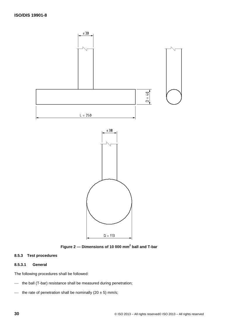
ISO/DIS 19901-8
30 © ISO 2013 – All rights reserved© ISO 2013 – All rights reserved
Figure 2 — Dimensions of 10 000 mm2 ball and T-bar
8.5.3 Test procedures
8.5.3.1 General
The following procedures shall be followed:
the ball (T-bar) resistance shall be measured during penetration;
the rate of penetration shall be nominally (20 ± 5) mm/s;
ISO/DIS 19901-8
© ISO 2013 – All rights reserved© ISO 2013 – All rights reserved 31
for tests with penetration deeper than 5 m, the inclination of the rod attached to the ball (T-bar) shall be measured;
readings from all sensors shall be recorded at least once per second (i.e. for every 20 mm of penetration);
the ball (T-bar) resistance should be measured during retraction at a nominal rate of 20 ± 5 mm/sec, if agreed in the project specification.
NOTE Many systems allow measurement of ball (T-bar) resistance upon retraction.
Cyclic testing can be included to obtain a measure of the remoulded shear strength.
If cyclic ball (T-bar) tests are carried out, these shall be done on ball (T-bar) penetration and comprise cycles of minimum up and down distances of at least 0,15 m (0,20 m) or three times the diameter of the ball (T-bar), whichever is greater, at a nominal rate of 20 mm/s. Ten full cycles should be carried out, unless no further degradation in ball (T-bar) penetration resistance is evident over three or more cycles.
In some cases, important information can be obtained by carrying out tests at rates of penetration outside those given above. If such tests are carried out, results shall clearly be marked with a note that a non-standard penetration/extraction rate has been used.
The thrust machine should push the instrument such that the axis of the pushing force is as close to vertical as possible. The axis of the penetrometer shall correspond to the loading axis at the start of penetration.
8.5.3.2 Accuracy requirements
Taking into account all possible sources of error and using the complete field measurement system, the allowable minimum accuracy of test measurements shall be better than the largest of the following values:
for penetration resistance: 5 % of the measured value or 20 kPa, whichever is larger;
for inclination: 2° (if applicable).
The allowable minimum accuracy for resistance shall apply relative to seafloor.
The allowable minimum accuracy for penetration depth should be estimated in accordance with depth accuracy recommendations as provided in Clause 6.
The resolution of the measured results shall be better than one-third of the required minimum accuracy.
The requirement for the load-cell measuring the ball (T-bar) resistance shall be the same as for the CPT/CPTU, see 8.3.3.6.
8.5.4 Presentation of test results and reporting
The reporting shall comply with 8.2. In addition, the area ratio, a, of the ball (T-bar) shall be listed. The measured results shall be presented in digital form, consisting of the following:
depth below seafloor, expressed in metres;
ball (T-bar) resistance, qm, during penetration and extraction, expressed in MPa or kPa;
inclination (if measured), expressed in degrees.
In addition, the net ball (T-bar) resistance should be given according to the following simplified formula [see Randolph (2004)]:
qball (qT-bar) = qm − [σv0 + uo(1 −a)](As/Ap)
where

ISO/DIS 19901-8
32 © ISO 2013 – All rights reserved© ISO 2013 – All rights reserved
qball (qT-bar) is the net penetration resistances for ball (T-bar);
qm is the measured penetration resistance;
u0 is the applicable hydrostatic water pressure at the mid-height of the ball (T-bar);
σvo is the in situ total vertical stress;
Ap is the projected area of the penetrometer in a plane normal to the shaft;
a is the net area ratio = An/As, where
An is the area of the load cell or shaft where pore pressure can act,
As is the cross-sectional area of the connecting shaft.
For the reporting of cyclic tests, the net remoulded ball (T-bar) penetration resistance denoted as:
qball,rem (qT-bar,rem)
should be determined as the average penetration and extraction resistance over the last cycle (see 8.6.3).
If full degradation has not occurred, remoulded shear strength from qball or qTbar should not be reported.
It is recommended that reference readings be documented following the procedure outlined in Annex D.
For all test types, the measured ball (T-bar) resistance shall be corrected relative to seafloor.
In general, test results shall be plotted with a depth scale of 10 mm = 1 m, but for shorter profiles, e.g. for pipeline investigations, an enlarged scale can be used.
The zero reference for ball (T-bar) tests shall be the seafloor for non-drilling mode operation (see Clause 6). For vessel based drilling mode and downhole testing the zero reference shall be the deck level, but the reference readings at the bottom of the borehole shall also be recorded and compared to theoretically calculated values. Both non-drilling and drilling mode tests shall be reported for all measurements with reference to seafloor. For seafloor drilling mode testing the zero reference shall be at seafloor, or a fixed distance above seafloor.
The scale for presenting the measured ball (T-bar) resistance during penetration and retraction shall be selected to suit the soil conditions.
The results of cyclic ball (T-bar) tests should be included in the main plot as well as in an enlarged plot in order to illustrate the results in adequate details.
8.6 Seismic cone penetration test (SCPT/SCPTU)
8.6.1 General
The seismic cone penetrometer, in addition to the standard CPT/CPTU sensors (see 8.3), has one or more seismic receivers that detect shear wave energy penetrated by a specific source deployed at the seafloor which is integral to the system. A suitable seismic source and a seismic cone penetrometer allow the execution of a downhole seismic test, which provides shear wave velocity, typically SH waves propagating vertically. For the CPTU parameters, the specifications in 8.3 are valid.
A single seismic test event may be agreed, for example for earthquake studies requiring an approximate average shear wave velocity for depth range from the seafloor to 80 m depth.

ISO/DIS 19901-8
© ISO 2013 – All rights reserved© ISO 2013 – All rights reserved 33
The following subclauses give specifications/requirements for the seismic part of the SCPT/SCPTU, which basically follow the requirements and reference information presented in ASTM D7400.
8.6.2 Equipment
The geometry and dimensions of the seismic cone penetrometer shall be in accordance with the requirements outlined in 8.3.2, with the exception that the diameter of the cone penetrometer at the location of the seismic receiver(s) should be greater than that of the sections immediately below the instrumentation package, in order to promote good coupling between the receiver(s) and the surrounding soil. Typical receivers include uni- or multi-axial geophones or accelerometers, either located at effectively one point, or located at two points in the same tool (dual-element seismic cone penetrometer with receivers separated by a fixed distance).
The seismic source can be installed on the seafloor frame used for the cone penetration test or at a different position on the seafloor. In both cases, the horizontal distance between the seismic source and the axis of the seismic cone penetrometer should be determined accurately.
A horizontal hammer can be used as a seismic shear wave source, the important issue being that a clear shear wave with high repeatability signal can be produced that can be readily identified by the seismic receiver(s).
NOTE 1 ASTM D7400 offers various recommendations about frequency for seismic receivers.
NOTE 2 Improved quality of measurement of interval shear wave velocity, vs, can be achieved by using a dual-element seismic cone penetrometer.
8.6.3 Test procedures
The project specifications shall include:
a) the type of seismic cone penetrometer, single element or dual element;
b) the test depth or vertical test spacing;
c) termination criteria.
NOTE 1 Shear wave velocity cannot reliably be measured in the upper 2 m to 5 m below seafloor, depending on the system characteristics and site conditions.
Termination criteria may include an agreed maximum test depth or a minimum signal-to-noise ratio combined with a maximum number of signal stacking events. Achievable test depth depends on factors such as deployed system characteristics, interaction of the seismic source with the upper seabed, soil conditions at depth and interference from nearby objects. Termination criteria for the CPTU (see 8.3.3.6) can also be taken into account.
The test procedure consists of activating the seismic source and receiving the generated signals at the seismic receivers. This is usually done during an interruption in cone penetration. However, some systems allow continuous operation of the seismic source and receivers during cone penetration. If cone penetration is interrupted, then multiple activation of the seismic source at a single depth can improve data quality, particularly when deploying a seismic source that generates shear waves in two opposite horizontal directions or when applying the "stacking method" [see e.g. Peuchen et al. (2002)].
A triggering signal shall be generated at the time the seismic source is activated, i.e. at the start of propagation of shear waves. The triggering signal and the measurements from the seismic receivers in the seismic cone penetrometer shall be recorded as discrete time histories.
A recommended minimum sampling interval is 0,025 ms.
The accuracy requirement for average shear wave velocity shall be ± 10 % for a straight-line slant distance from source to receiver and assumed zero depth uncertainty.
NOTE 2 A single test with a dual-element seismic cone penetrometer provides three velocities, one average velocity from source to upper seismic receiver, one average velocity from source to lower seismic receiver and an average velocity

ISO/DIS 19901-8
34 © ISO 2013 – All rights reserved© ISO 2013 – All rights reserved
for the zone between the two receivers. The accuracy for the average velocity is largely unaffected by depth uncertainty and travel path. Other shear wave velocities will have lower accuracies, which can be calculated from an estimate of the uncertainties in travel path distance, either from source to receiver or from the relative distance between two test depths in a single profile. A single test with a single-element seismic cone penetrometer provides one velocity only. Two tests with a single-element seismic cone penetrometer in a single profile provide the opportunity for determination of three velocities, one from source to upper test depth, one from source to lower test depth and a differential velocity for the zone between the two test depths. Three or more tests provide additional opportunities for separating zones of interest.
8.6.4 Presentation of results
In addition to the requirements for presentation of the standard CPT/CPTU results given in 8.3.4, the following shall be presented:
type and description of the seismic source and the seismic receiver(s);
difference in depths between the seismic source and the position(s) of the seismic receiver(s);
the horizontal distance between the seismic source and the axis of the seismic cone penetrometer;
average, or interval, shear wave velocity, vs, for the depth interval(s) over which it has been measured, including:
the depth uncertainty according to Clause 6;
limitations of the methodology used;
assumed travel path for the seismic waves.
NOTE A travel path may not be a straight line for materials with an abrupt change in density or elasticity and in such cases Snell’s law of refraction can be used. With small offset distances relative to depth below seafloor, e.g. 2 m offset and 10 m depth below seafloor, this becomes less important.
8.7 Field vane test
8.7.1 General
Field vane tests (FVT) are undertaken to measure the intact, residual and remoulded shear strengths of clays with undrained shear strengths normally less than 100 kPa. However, the vane test can be used in clays with undrained shear strengths of up to 200 kPa.
8.7.2 Equipment
Vane blades should be rectangular. The ends of a vane blade may be flat or tapered as shown in Figure 3 and Figure 4. Vane blades should have a height (H) to diameter (D) ratio equal to 2 (see Figure 3). Maximum vane dimensions H × D of 200 mm x 100 mm are commonly used in soft soils with undrained shear strengths less than 25 kPa. Minimum vane dimensions of 80 mm × 40 mm are commonly used in clays with undrained shear strengths up to 200 kPa.

ISO/DIS 19901-8
© ISO 2013 – All rights reserved© ISO 2013 – All rights reserved 35
Key H Height of the vane s Blade thickness D Diameter of the vane d Diameter of the rod
Figure 3 — Design of vane (from ISO/DIS 22476-9)
Figure 4 — Example of tapered vane (from ASTM D2573)
The blade thickness, s, should be 0,8 mm ≤ s ≤ 3,0 mm
In very soft and sensitive clays, the blade thickness should not exceed 2,0 mm in order to limit the disturbance caused during vane insertion.
The diameter of the vane shaft, d, as well as possible welding seams in the centre of the vane, should be small enough to minimize soil disturbance.

ISO/DIS 19901-8
36 © ISO 2013 – All rights reserved© ISO 2013 – All rights reserved
The diameter of the vane shaft should be no greater than 16 mm in soft sensitive soils, with sufv < 12,5 kPa. However, the vane shaft shall be of such rigidity that it does not twist significantly under full load conditions. In clays with undrained shear strength higher than 100 kPa, the diameter of the vane shaft may exceed 20 mm.
The data acquisition system shall be such that the overall accuracy outlined in 8.7.3 is maintained.
The resolution of the measurement system shall be better than one-third of the required accuracy applicable to the application class given in Table 4.
8.7.3 Test procedures
For field vane tests, application classes as defined in 6.2 of ISO/DIS 22476-9:2012 should be adopted. Equipment and procedures to be used should be selected according to the required application class as shown in Table 4. Some offshore-specific modifications have been added after this table.
Application classes for field vane tests are defined as follows:
Application Class 1: for special purposes (for example to measure soil stiffness and/or if requiring high accuracy in extremely soft soils);
Application Class 2: for an accurate value of undrained shear strength of soft to very soft soils;
Application Class 3: for stiffer soils.
Equipment and procedures, together with the reading intervals, shall be selected according to the application class, as shown in Table 4.
The uncertainty on depth of the FVT applies relative to the seafloor, see Table 1 on deployment.
If all possible errors are added, the accuracy of the recorded measurements should be better than the largest values given in Table 4. The accuracy analyses shall include sources of friction other than those caused by the blade together with data acquisition, calibration and dimensional errors.
NOTE Achievable accuracy is a function of the dimensions of the vane used in the test. The use of larger vanes will result in higher accuracy, but a smaller measurement range (see Table 4).

ISO/DIS 19901-8
© ISO 2013 – All rights reserved© ISO 2013 – All rights reserved 37
Table 4 — Application classes for the vane test
Application Class
Allowable minimum accuracya Maximum rotation between
measurements degrees
Suggested use
Soilb Interpretation
1
sufv
rotation angle
2 kPa 1° or 1 %
1
A to C
H
2
sufv
rotation angle
4 kPa 5° or 1 %
2
A to E
H, H*
3
sufv
rotation angle
10 kPa 10° or 1 %
5
B to E
H*
NOTE For extremely soft soils, even higher demands on the accuracy may be needed.
a The allowable minimum accuracy of the measured parameter is the larger value of the two quoted. The relative accuracies apply to the measured value and the measuring range. b A: Homogeneous layers of very soft clay, 0 kPa to 12,5 kPa;
B: Soft clay, 12.5 kPa to 25 kPa;
C: Firm clay, 25 kPa to 50 kPa;
D: Stiff clay, 50 kPa to 100 kPa; E: Very stiff clay, 100 kPa to 200 kPa. c H interpretation in terms of engineering parameters with associated low uncertainty level; H* interpretation in terms of engineering parameters with associated high uncertainty level.
If the project specification does not define which application class is required, then Application Class 2 is default.
The minimum allowable accuracy for penetration depth shall be estimated in accordance with depth accuracy requirements as presented in Clause 6.
For testing in drilling mode, the vane blade shall be pushed at least 1,0 m below the bottom of borehole before a vane test is commenced. For vane tests carried out in non-drilling mode, the depth intervals between tests shall be at least 0,5 m.
The pushing rate should not exceed 25 mm/s. The recommended time from the instant when the desired test depth has been reached to the beginning of the test (waiting time) should be between 2 minutes and 5 minutes.
The rotation of the vane should be smooth and for the initial test (undisturbed) be 6°/min to 12°/min. The undisturbed vane shear strength shall be calculated from the maximum torque as given in 8.7.4. The project specification should specify whether residual and/or remoulded shear strength shall be measured in addition to the intact vane shear strength.
To measure residual shear strength, sufv,res, during the initial test, the vane shall be rotated until the torque is levelling off or to a rotation of 180°, whichever is reached first. The minimum torque thus obtained shall be used to calculate the residual strength.
The residual strength shall not be used to calculate sensitivity, St,fv.
To measure remoulded shear strength, sufv,rem, the vane should preferably be rotated at least 10 times at a rate ≥ 360°/min. As an alternative, vane rotation for the remoulding phase may be at a speed > 6°/min and continue until the torque difference is less than 2 % per rotation, with a maximum of 10 rotations.
At the end of the remoulding rotations, the remoulded shear strength shall be measured without delay, using a rotation rate equal to that used for intact shear strength.

ISO/DIS 19901-8
38 © ISO 2013 – All rights reserved© ISO 2013 – All rights reserved
The remoulded shear strength can be used to calculate sensitivity as described in 8.7.4.
The sensor for measuring the torque during vane testing shall be calibrated at least once a year and before each project. If the sensor is loaded close to its maximum or any damage is suspected, it shall be checked and recalibrated. Function checks shall be carried out in the field. Management of metrological confirmation applicable for a vane test shall be in accordance with ISO 10012. The equipment shall undergo regular maintenance, checking and calibration, such that the accuracy required for the application class can be verified.
8.7.4 Presentation of results
For each vane test, the following information shall be given in addition to the requirements listed in 8.2:
the complete curve of shear stress versus rotation, expressed in degrees;
the time to failure;
the formula used to calculate the vane undrained shear strength, suv, including the assumption made for shear stress distribution on ends of the vanes;
description of any corrections of results due to friction on rod between vane blade and torque sensor, ambient pressure effects, etc.;
the following vane shear strengths:
initial undisturbed shear strength, sufv;
residual shear strength, sufv,res, if applicable;
remoulded shear strength, sufv,rem, if applicable;
sensitivity, St,fv = sufv/sufv,rem, if applicable.
For standard vanes with H/D = 2.0, the undrained shear strength value should be calculated as given in Clause 7 of ISO/DIS 22476-9.
sufv = 0,273(torque/D3)
The insertion method and test procedure used shall be described, giving particular information about
the method for insertion and penetration of vanes;
possible rotation rate settings available;
the mechanical reaction used to resist the torque developed between the vane and the soil.
8.8 Other in situ tests
8.8.1 General
In addition to the in situ tests specified in the previous subclauses, other appropriate tests may be needed or proposed for a complete soil investigation programme. Such tests shall be specified separately.
Examples of such in situ tests are:
electrical conductivity cone penetration test;
ISO/DIS 19901-8
© ISO 2013 – All rights reserved© ISO 2013 – All rights reserved 39
temperature cone penetration test;
thermal conductivity by needle probe test;
hydraulic fracture test;
pore water/gas sampler with test probe;
ambient pressure sampler;
dilatometer test
Some additional guidance is provided in Annex D.
8.8.2 Documentation requirements
All other in situ test equipment shall be accompanied by the following documentation:
description of equipment and purpose of test;
geometry of equipment;
calibration of sensors, with a statement on accuracy of measurements;
data acquisition system, with statement on resolution of measured results;
test procedure;
presentation of results.
9 Sampling
9.1 General
The discussion on sampling in this clause is primarily for use with soils such as siliceous sands and clays (conventional soils). Special consideration may be required in unconventional soils like calcareous soil, silt, sensitive clay, boulder clay, etc. (see Table A.3 for a list of more unconventional soils).
9.2 Purpose of sampling
The main purpose of sampling is to obtain suitable and representative soil material of all significant layers for description and laboratory testing.
The selection of the appropriate sampling tools and deployment modes for particular soil conditions fundamentally affect the sample quality and shall be considered in relation to the objectives of the sampling. See 10.5 (Table 6) for specific guidance on sample quality, and see 10.1 and Annex E for specific guidance on selection of appropriate sampling equipment (application classes and suitability classes).
Efforts shall be made to minimize sample disturbance when sample quality is important, and the aim shall then be to obtain undisturbed samples as defined in 3.37 and sampling tools should be selected accordingly, see E.1 for guidance.
In some cases a lower sample quality may be appropriate, if the primary objective of the sampling is for example:
soil type confirmation for interpretation of in situ tests;
continuous coverage of the soil vertical profile (soil sample disturbance is a lesser issue); or
ISO/DIS 19901-8
40 © ISO 2013 – All rights reserved© ISO 2013 – All rights reserved
to obtain a large sample volume (volume is more important than quality). In such cases, other types or variations from standard equipment may be preferable, e.g. much larger diameter or greater length of sample tubes.
9.3 Sampling systems
Deployment of soil investigation equipment is categorized in Clause 6 as methods to recover geotechnical data from the seabed. “Drilling mode” systems utilize an iterative process to progressively recover discrete soil samples from the seabed, with a borehole progressed via rotary drilling between sampling runs. “Non-drilling mode” systems progress sampling tools in a single stroke into the seabed, with sampling being terminated either at the point of maximum stroke of the tool, at a predetermined depth, or due to refusal associated with local seabed obstructions and/or accumulated penetration resistance.
The type of equipment selected generally governs the maximum depth from which a sample can be recovered, as well as the quality and recovery ratio of sample that can be achieved. Ideally, the client should be satisfied that the selected method of deployment will have the capacity not only to penetrate to sufficient target depth, but also to acquire samples of sufficient quality to meet project objectives.
9.4 Selection of sampling tools
9.4.1 General
The choice of sampling tools shall be made with consideration of the actual soil conditions, as well as the type of laboratory testing to which the samples are subjected. In many cases, marine soil investigations are undertaken at previously unexplored locations, where there is little knowledge of the geology. In such cases the client shall consider mobilizing a range of soil-sampling tools, capable of sampling a range of soil types.
The length of sample that can be obtained using a sampling tool is largely dependent on:
the geometry, size and characteristics of the sampler;
the soil type;
the available penetration force and how this is applied using the deployment equipment.
Optimum sample quality is largely dependent on selection of the appropriate sampling device for the soil conditions encountered.
Sample tubes shall be carefully selected for the expected soil conditions. The quality of the sample is influenced by sample tube geometry. Normally a range of tubes will be available.
The following minimum information is required for the sampling tool:
cutting shoe angle;
inside and outside diameters (inside clearance if applicable);
maximum sample length;
whether a piston is used or not;
inside liners or stocking (if applicable);
core catching system (if applicable);
steel material specification;
method of sealing sample tube if samples are not to be extruded offshore.

ISO/DIS 19901-8
© ISO 2013 – All rights reserved© ISO 2013 – All rights reserved 41
Stainless steel or other non-corrodible material shall be used to seal the samples within the tubes if they are not extruded offshore.
It is especially important that sample tubes are not re-used unless they have been cleaned and thoroughly checked for damage. Tubes with damaged tips shall be repaired to the same standard or discarded. Further guidance on sample tube selection and recommendations are provided in Annex E.
9.4.2 Drilling mode samplers
Drilling mode equipment may be used where there is a perceived risk that target penetrations might not be achieved by non-drilling methods. Equipment capable of sampling in drilling mode ranges from dedicated geotechnical drill ships (“vessel drilling”) to remotely controlled, seafloor-founded drill rigs (“seafloor drilling”). These types of systems can deploy sampling tools and acquire soil samples to depths in excess of 100 m below the seafloor.
For sampling tools deployed in drilling mode, a variety of samplers is available. A general guide to sampler types is presented in Table E.1.
To cover the expected range of soil types, a project specification shall specify which systems are to be available, e.g. for taking piston, push and hammer samples. For very soft to stiff clays, the order providing the best sample quality would usually be:
piston sampler;
push sampler, thin-walled;
push sampler, thick-walled;
rotary core sampler;
percussion/vibratory sampler;
hammer sampler.
In some cases, especially in very stiff/hard clays and cemented soils/weak rocks, the use of a rotary core sampler can give the best quality.
In order to avoid highly disturbed soil below the drill bit, a piston sampler can be pushed through this material and sampling can start at a lower level. It is important that retrieval and handling of downhole samplers are undertaken in such a way that any shock or vibration is minimized.
Specifications for drilling mode sampling equipment vary considerably across the industry, and specific details of the proposed sampling equipment shall be considered for final selection and acceptance. A summary of contractor-provided information is presented in Table E.2.
9.4.3 Non-drilling mode samplers
Sampling equipment deployed via non-drilling methods can be appropriate where there is a reasonable degree of confidence that target depths can be reliably achieved in the geology expected. Sampling equipment deployed using such systems can range from very sophisticated seafloor-founded push frames, capable of recovering very high quality samples, to very simple seafloor samplers deployed via winch, which have a limited capacity to penetrate as well as limited ability to acquire high quality samples. With a few exceptions, all these systems are generally limited to penetrations less than 25 m below seafloor. However, penetrations in excess of 40 m are possible using specialist equipment within very soft seabed.
Sampling tools deployed in non-drilling mode provide more limited options and most devices are ideally suited to soft, fine-grained materials that offer little resistance to barrel penetration. Deployment of such tools in hard soil conditions results in limited depth penetration and sample recovery, and with increased risk of damage to the equipment. A general guide to sampler types available for non-drilling mode is presented in E.1.3 and Table E.3.

ISO/DIS 19901-8
42 © ISO 2013 – All rights reserved© ISO 2013 – All rights reserved
The following non-drilling mode samplers are frequently used in the industry:
piston corer with fixed reference to seafloor;
piston core sampler without a fixed reference (Kullenberg type corer);
gravity core sampler (without piston);
vibro-core sampler;
box core sampler;
grab sampler.
Further information on the use of these samplers is provided in E.1.3.
Specifications for non-drilling mode sampling equipment vary considerably across the industry, and specific details of the proposed sampling equipment shall be considered for final selection and acceptance of equipment. A summary of contractor provided information is presented in E.1.3.8 and Table E.4.
Operating and handling procedures that provide a demonstrated consideration of the sample history, from initial setup of the sampler prior to sampling to delivery to the onshore soil-testing laboratory, shall be provided for review by the client.
9.5 Sample recovery considerations
Sample loss is observed when the length of sample acquired (as measured on deck level) is less than the penetration of the sampler. This can be positive (material is lost) or negative (material has expanded or recovered from previous sampling attempts in the case of coring), and is a result of sample loss, compression, stretching or expansion. Sample loss also affects data depth accuracy as described in Clause 6.
Sample loss can be much more prevalent in non-drilling mode, where longer samples are generally recovered in a single sampling stroke.
Sample loss can occur due to one or more of the following events:
loss of sample from the bottom end of the sampler during retrieval;
densification of sample within the tube/liner due to shock or vibration;
loss and/or segregation of very soft soil due to fluidization;
settling of soil when the inside clearance ratio Ci (see subclause E.1.2.3) of the sampler is greater than zero;
soil expansion due to the presence of reactive clays, dissolved gases and/or stress release;
plugging of the cutting shoe during sampler penetration;
piston accelerations that are out of phase with sampler penetrations [see Bourillet et al. (2007) and Buckley et al. (1994)];
washing out/erosion of sample due to excessive exposure to drilling fluid during rotary coring (not relevant for non-drilling mode samplers);
loss of sample due to soil type, e.g. gravel, loose cohesionless soils, frozen soils, rock, etc.

ISO/DIS 19901-8
© ISO 2013 – All rights reserved© ISO 2013 – All rights reserved 43
Identification of the exact cause of sample loss is often difficult, and in many cases only an estimate can be made of the depth interval where sampling was unsuccessful. Gaps in sample continuity can be attributed to geology, a fault of the sampling tool, poor control of the tool itself during penetration or poor drilling resulting in disturbance of soil in the sampling zone. For this reason, maintenance of detailed operator’s logs, where practicable, can provide a useful additional tool for the identification of problematic areas in which sample loss may have occurred.
Where loss is identified within a sample run, an experienced engineer may estimate the likely depth zone over which this occurred. In addition to operator logs, the superposition of nearby in situ test data can also assist in making an appropriate estimate of where this has occurred. If the location is unknown, the log shall indicate this and show sample loss/extension at the bottom of the sample. Shallow geophysics may also assist in evaluation of where sample loss has occurred, e.g. high frequency sub-bottom profilers.
For samplers with no fixed seafloor reference, the measurement of penetration is uncertain and sample loss or recovery ratio is difficult to estimate. Such samples cannot be used for accurate depth determination of soil layers or properties.
9.6 Handling, transport and storage of samples
9.6.1 General
Sample handling, transport and storage practice shall suit the purpose of sampling; and the required procedures shall be stated in project specifications.
NOTE 1 ISO 22475-1 provides guidance on handling, transport and storage of samples.
NOTE 2 Agreements normally include a fixed or flexible sample storage period at a nominated storage facility or onshore laboratory and, if required, with defined storage conditions, for example such as temperature and humidity control.
Sample tracking is important, and each sample shall have a unique identification (ID), either by manually logging the borehole number, sample number, depth, etc., as specified, or by an ID link with a database, e.g. bar coding, RFID, etc.
The contractor shall prepare and maintain a sampling record which normally includes information such as:
ID of borehole and sample;
date of sampling;
location coordinates;
water depth;
depth below seafloor;
type of sampler;
dimensions of sampler;
length or volume of sample collected;
whether sample is extruded or sealed in tube or liner, etc.
The sampling record shall be completed as soon as practicable following sample acquisition.
NOTE 3 ISO 22475-1 includes guidance on sampling records.
9.6.2 Offshore sample handling and logging
Following acquisition the sample shall be handled in such a way that sample disturbance is avoided or minimized.
ISO/DIS 19901-8
44 © ISO 2013 – All rights reserved© ISO 2013 – All rights reserved
For samples suspected to consist of contaminated material, special precautions shall be taken and expert guidance sought depending on the state and type of any such material.
For drilling mode samples, any "cuttings" and drill mud shall be removed from the top of the cylinder before the total length of sampled soil is measured. Samples recovered in long plastic liners can be carefully cut into smaller lengths of 0,5 m to 1 m, where the material strength permits.
The decision whether or not to extrude soil samples on site is a function of the material, the purpose of sampling and the requirements for offshore testing. Generally, only soil samples that are cohesive in nature and that will remain in a relatively undisturbed state after extrusion should be extruded on site, although sand samples may also be considered for extrusion. Other samples should be retained within the sample tubes. Dense fine-sand samples and sand samples containing silt or clay are normally best kept in the sample tubes.
The top and bottom of sample or sample segments shall be clearly marked.
Extrusion of samples shall be carried out very carefully. If an extruder is used, it shall provide a continuous rate of displacement (nominal minimum speed 10 mm/s) and shall have an adaptor custom-fitted to the dimensions of samples recovered. The extruder shall not impart excessive vibrations to the sample.
If samples are suspected to contain gas, special precautions shall be considered which shall particularly address issues of personnel safety.
A suggested procedure for handling of extruded samples is given in E.2.2.1.
For tube samples not extruded offshore, soil description and index tests according to Annex F may be performed at the sample ends. A suggested procedure for handling of these samples is given in E.2.2.2.
Samples recovered by rotary coring shall be carefully handled, logged and prepared for transport, and guidance on this issue is provided in E.2.2.3.
Samples acquired by grab or box core methods shall be considered for sub-sampling or otherwise logged and handled according to project specifications. Guidelines and suggestions are provided in E.1.3.7 for grab samples and E.1.3.6 for box core samples.
9.6.3 Offshore storage
Sample storage offshore shall be designed to avoid further sample disturbance. Factors to be considered are
exposure to high temperatures;
freezing;
chemical changes;
vibration or impact/shock of any kind;
moisture control.
For samples acquired from the seabed at temperatures close to 0° C, active cooling shall be considered (reefer container) at 4° C. Similarly, for investigations in hot climates, active cooling shall be considered. Further guidance on offshore storage is provided in E.2.3.
9.6.4 Onshore transport, handling and storage
Appropriate procedures for sample transport, handling and storage prior to arrival at the onshore laboratory shall be implemented. In general, conditions of temperature, moisture, vibration and shock should be controlled or packing shall be sufficiently robust to avoid damage to samples. Freezing shall be avoided. Particular care shall be taken to ensure the samples do not experience freezing conditions during air freight.

ISO/DIS 19901-8
© ISO 2013 – All rights reserved© ISO 2013 – All rights reserved 45
Further guidance is provided in E.2.4.
10 Laboratory testing
10.1 General
During the execution of a geotechnical laboratory test programme, tests shall be performed in accordance with recognized standards or codes or other recognized procedures. This Clause 10 and Annex F cover testing of soils performed in geotechnical laboratories both offshore and onshore.
Annex F provides procedures for conducting the more common laboratory tests, with a primary focus on laboratory testing of saturated soils. It does not cover testing of contaminated soils.
The standards cited in Annex F are the recommended ones and are primarily those of ISO and ASTM, where available, although other standards may be used. The relevant standards and procedures to be used for the laboratory testing and the form of presentation and transmission of results, such as tables and figures, should be given in the project specifications. However, if such requirements are not given in the project specifications, then the standards and procedures described in Annex F shall apply.
Requirements presented in this part of ISO 19901 are primarily for testing of conventional soils such as siliceous sands and clays. Samples selected for a particular laboratory test should match the intended scope of that test. Consideration should be given to alternative and supplementary requirements when performing marine soil investigations in unconventional soils like calcareous soil, silt, sensitive clay, boulder clay, etc (see Table A.3 for a list of more unconventional soils).
This part of ISO 19901 does not cover details of laboratory testing of rock, however F.13 provides references to other standards containing guidance for classification and laboratory testing of rock materials.
Many aspects of laboratory testing of soils, such as instrumentation, data acquisition, calibrations, corrections, soil preparation and evaluation of sample quality, are common to a variety of tests. To avoid repetition, background information for such common topics is presented in 10.2 to 10.6. Some specific test requirements are given in the relevant subclauses in Annex F.
The applicability of measured data from tests that require the use of intact samples is significantly influenced by sample quality. It is thus important to evaluate sample quality whenever possible.
This part of ISO 19901 describes five soil sample “application classes” (which in EN 1997-2 are called “quality classes”), with Classes 1 and 2 for undisturbed samples and Classes 3 to 5 for disturbed samples, as follows:
Samples of Classes 1 and 2 have undergone no or only slight disturbance to the soil structure during sampling and handling.
Class 3 samples contain all of the constituents of the in situ soil in their original proportions and the natural water content has not changed. The general arrangement of the different soil layers can be identified. However, the soil structure has been disturbed.
Samples of Classes 4 and 5 are highly disturbed with significant changes to the soil structure. The general arrangement of the different soil layers cannot be identified accurately. The water content of the sample may not be representative of the natural water content.
Table 5 identifies the five classes with respect to the soil properties that are assumed to remain unchanged during sampling, handling, transport and storage, and the geotechnical properties that can be measured from each application class.

ISO/DIS 19901-8
46 © ISO 2013 – All rights reserved© ISO 2013 – All rights reserved
Table 5 — Application classes of soil samples for laboratory testing (from EN 1997-2:2007)
Soil properties Application classes
1 2 3 4 5
Unchanged soil properties:
particle size x x x x
water content x x x
density, permeability x x
compressibility, shear strength x
Properties that can be determined:
sequence of layers x x x x x
boundaries of strata – broad x x x x
boundaries of strata – fine x x
Atterberg limits, particle density, organic content, carbonate content x x x x
water content, pore fluid salinity x x x
density, permeability x x
compressibility, shear strength x
10.2 Presentation of laboratory test results
Presentation of the laboratory test results shall include the standard applied and title for each of the laboratory tests conducted.
Presentation of laboratory test results (including plots and tables) shall include for each test specimen
site location;
specimen identification (e.g. borehole or box core number, sample number, section number);
sampling depth.
Other relevant test and specimen information, where applicable, include:
specimen dimensions;
unit weight (total and dry);
initial and final water contents;
initial degree of saturation;
specific gravity of soil grains (unit weight of solid particles);
initial void ratio;

ISO/DIS 19901-8
© ISO 2013 – All rights reserved© ISO 2013 – All rights reserved 47
plasticity characteristics (Atterberg limits);
estimate of the in situ effective vertical stress.
Any sample deviations from the test requirements (e.g. insufficient sample available to perform particular tests, lack of undisturbed samples, test run on specimens that were dimensionally out of standard) shall be identified and documented.
Additional requirements for presentation of laboratory test results are given in the individual laboratory test subclauses presented in Annex F.
10.3 Instrumentation, calibration and data acquisition
The requirements given in ISO 10012 for measurement processes and measurement equipment as components of a measurement management system should be applied.
The instrumentation for laboratory testing may include mechanical devices (e.g. dial gauge, pressure gauge, proving ring, etc.) and electronic devices (e.g. displacement transducer, pressure transducer, load cell, etc.). Such instrumentation shall be calibrated as appropriate, and the calibration data shall be available upon request. Recommendations on the frequency of calibration of instrumentation, commonly every 6 to 12 months, are given by international standards such as ISO 10012 and ASTM D3740. The procedures and equipment used to perform the calibrations and the calibration frequency shall be documented.
NOTE Procedures for calibration are given in Head (1986) and ASTM D5720 for pressure transducers, and in ASTM D6027 for linear displacement transducers.
Instrumentation selected for specific tests shall meet the accuracy and capacity required for the measurement being made, where such accuracy and capacity are specified. This largely depends on the type of test being conducted, target displacement, pressure or force levels, and soil strength and stiffness. Accuracy requirements for laboratory tests that make extensive use of instrumentation (e.g. triaxial, consolidation and direct shear) are given in the specific test subclauses in Annex F.
Electronic-based data acquisition systems generally consist of a power supply, cabling, analog to digital (A/D) conversion electronics, signal conditioning, multiplexer, and software. The bit resolution and voltage range of the data acquisition system shall meet the requirements of the individual transducers being monitored, which in turn shall fulfil the capacity and readability requirements for each test parameter being measured. The frequency of readings that the data acquisition system is capable of accurately recording shall meet the requirements for the specific test being conducted. Requirements for the reading frequency for laboratory tests that make extensive use of electronic instrumentation are given in the relevant subclauses in Annex F.
Corrections shall be applied to measured test data (where relevant) to account for apparatus deformation, changes in specimen area, piston friction, filter paper resistance and membrane resistance. Such corrections are most commonly applicable to consolidation, triaxial, direct shear and resonant column testing. Correction requirements are given in the relevant subclauses in Annex F. The procedures and equipment used to determine these corrections shall be documented and reported (when required).
10.4 Preparation of soil specimens for testing
10.4.1 Minimum sample size and specimen dimensions
Annex L of EN 1997-2:2007 presents summary tables of minimum requirements for sample mass and specimen dimensions for most of the commonly conducted laboratory tests. Test standards (e.g. ISO and ASTM) that also specify these requirements are listed in the relevant subclauses in Annex F.
10.4.2 Preparation of disturbed samples
Soil samples should not be dried prior to testing, unless otherwise specified, but should be used in their natural state. If drying is required, options include air or oven drying. The method of drying used shall be documented.
ISO/DIS 19901-8
48 © ISO 2013 – All rights reserved© ISO 2013 – All rights reserved
Aggregations of particles should be broken down in such a manner as to avoid crushing of individual particles. The method used should be no more severe than that applied by a rubber-tipped pestle.
Disaggregated soil should be thoroughly mixed before subdividing. Subdivision of disaggregated soil should be conducted using methods such as riffling or cone-and-quartering. This procedure should be repeated until a representative sample of the specified minimum mass is obtained for use as a test specimen.
If it is necessary to remove oversized particles to prepare a test specimen, the size range and the equivalent dry mass of the oversize material should be reported.
10.4.3 Preparation of undisturbed specimens (fine-grained soils)
The representativeness of results from tests that require undisturbed samples (e.g. consolidation, triaxial, direct shear, permeability tests) is significantly influenced by sample quality. Selection of undisturbed samples for testing should be guided by all information that is available on the potential quality of the samples. X-rays and computerized tomography (CT) scans (see F.2.4) provide valuable non-destructive visual information on sample quality, and can be used to guide selection of test samples. Quantification of sample quality for low to medium over-consolidation ratio clays can be conducted using the a posteriori εvol or ∆e/e0 methods described in 10.5.
Any unused portions of an undisturbed sample that may be needed for future testing should be properly re-sealed, labelled and returned to storage. Guidelines for sample sealing and storage are given in E.2 in this part of ISO 19901, and in ISO 22475-1.
Trimming of undisturbed specimens should be conducted in such a manner as to minimize disturbance and such that no loss of water occurs. At all times the specimen should be supported on a rigid surface, and all handling and transfers of the specimen shall be conducted using rigid support devices (e.g. plates, cylinders) and handling should be kept to a minimum.
Trimming of specimens for triaxial, consolidation, direct shear and permeability tests should be conducted using suitably dimensioned trimming devices, together with sharp and clean trimming tools (wire saw, scalpel, knife, straightedge, etc.). Suitable trimming devices for cylindrical specimens include a trimming lathe and turntable or cutting ring. For consolidation specimens, the cutting ring may be part of the confinement ring. Cutting rings should have sharp edges, a highly polished inner surface, and coated with a low-friction lubricant (e.g. low viscosity silicone oil). Further details concerning sample trimming equipment are presented in the relevant test subclauses in Annex F.
Special procedures are required for trimming and set-up of specimens having undrained shear strength su less than about 5 kPa. The procedure and equipment used should be documented and reported (when required).
10.4.4 Laboratory-prepared samples and specimens
Laboratory-prepared samples include compacted and reconstituted samples.
Soil samples can be compacted to form a test specimen, either by using a specified compacting force at a specified water content or by achieving a specified dry density at a specified water content. Compaction options include tamping, kneading, ramming, rodding, vibration and static loading. The exact procedure required to achieve a specified dry density should first be determined by trial. Specimens for consolidation, triaxial, direct shear and permeability tests may be compacted into a suitable mould that is either larger than or the same size as the required test specimen. If the mould is larger than the test specimen, the compacted sample should be removed from the mould and trimmed to the required test specimen size using the procedures described in 10.4.3 for undisturbed samples. Care should be taken to avoid the formation of voids within the compacted sample or specimen. Samples containing clay should be left to stand for at least 24 h at the required water content for the test. The compaction equipment and sample preparation procedures should be described in detail within the test procedures.
In addition to compaction, reconstituted samples or specimens of sands can be prepared using air or water pluviation. The exact procedure including, for example, drop height and rate of pluviation required to achieve a specified dry density should first be determined by trial. Specimens for consolidation, triaxial, direct shear and

ISO/DIS 19901-8
© ISO 2013 – All rights reserved© ISO 2013 – All rights reserved 49
permeability testing shall be pluviated into the test specimen container (e.g. rigid or temporarily supported flexible membrane). The pluviation equipment and procedures should be described in detail within the test procedures.
Reconstituted samples or specimens of fine-grained soils should be prepared by thoroughly mixing the soil to form a homogeneous slurry having a water content greater than approximately 1,3 times the liquid limit. It is preferable that the soil be prepared starting from the natural water content. The mixing water used to prepare the slurry may be either that of the appropriate ionic content, de-ionized, or distilled. The water content should be high enough to allow the slurry to be poured into a consolidation cell. Consolidation of the reconstituted sample or specimen should be conducted in a manner similar to that of the consolidation test as described in F.3. The initial loads should be small enough to allow the specimen to stiffen, so as to prevent extrusion of material upon additional loading. The final consolidation stress should be sufficient to allow the sample to be extruded from the consolidation cell, and handled for sealing and subsequent trimming of test specimens. The equipment and procedures used for preparing reconstituted samples should be described in detail within the test procedures.
10.4.5 Preparation of remoulded samples
Remoulding of fine-grained soils can be achieved by thoroughly mixing, squeezing and kneading the sample without the loss of water. This can be achieved by placing the sample in a sealed plastic bag prior to remoulding.
The energy required to remould a soil depends largely on its water content relative to its liquid limit. Soils with low water content and low liquidity index are stiffer and more difficult to remould than those with water content greater than the liquid limit. Thus greater uncertainty can exist in how thoroughly remoulded very stiff samples are in comparison to soft, high liquidity index samples. A check of the thoroughness of remoulding can be performed by periodically conducting a strength index test (e.g. fall cone test) on the sample during remoulding until a constant value of minimum strength is obtained.
A remoulded test specimen can be prepared by working the remoulded soil into an appropriate mould. This should be conducted as quickly as possible, to avoid a change in water content, and without entrapping air. The procedure used for preparing remoulded samples should be described in detail within the test procedures.
10.5 Evaluation of intact sample quality
While no definitive method exists for determining the quality of intact samples, valuable information can be obtained using the following qualitative and quantitative methods.
Qualitative (visual) assessment of sample quality can be made by examination of sample X-rays or CT scans as described in F.2.4. Petrographic examination of soil fabric is another method which is particularly useful in assessing the amount of disturbance in fine, fragile carbonate soils.
Quantitative assessment of sample quality for intact, low to medium over-consolidation ratio (OCR) clays can be made by measuring volume change at the estimated in situ stress state (σ'v0, σ'h0) during laboratory consolidation. The normalized sample quality parameter ∆e/e0 of Lunne et al. (2006) is computed as:
∆e/e0 = εvol(1 + e0)/e0
where
∆e is the change in void ratio;
e0 is the void ratio of the prepared specimen;
εvol is the volumetric strain (= ∆V/V0) from reconsolidation to (σ'v0, σ'h0);
σ'v0 is the in situ vertical effective stress;
σ'h0 is the in situ horizontal effective stress.

ISO/DIS 19901-8
50 © ISO 2013 – All rights reserved© ISO 2013 – All rights reserved
The values of ∆e/e0 and εvol should be computed and reported for laboratory consolidation tests conducted on intact clay soils (i.e. incremental load oedometer, constant rate of strain and anisotropic consolidation phase of strength tests such as triaxial and direct simple shear) provided the best estimate in situ effective stresses are given. The sample quality is determined using Table 6 for the method of Lunne et al. (2006). An alternative method is given by Terzaghi et al. (1996).
NOTE 1 The anisotropic consolidation stresses σ'vc = σ'v0 and σ'hc = σ'h0 can be directly applied in an anisotropically consolidated triaxial (recompression) test, whereas in tests with rigid confinement (e.g. incremental load oedometer, constant rate of strain, and the common form of direct simple shear) only σ'vc is applied/known, and an unknown value of σ'hc develops in the specimen. In such tests, εvol = εa (axial strain).
NOTE 2 The sample quality criteria in Table 6 is not valid for data from incremental loading (IL) tests that use long load durations (e.g. 24 h) because of added secondary compression. The sample quality criteria in Table 6 or the one given by Terzaghi et al. (1996) can be used if the IL test was conducted using relatively short load durations [e.g. 1 h to 3 h as suggested by Sandbækken et al. (1996)]. If longer duration load increments were used, then the deformation-time curves should be interpreted to determine the end of primary strain for the relevant load increments needed to estimate ∆e /e0.
NOTE 3 The criteria presented in Table 6 were developed based on results from laboratory tests performed on marine clays collected from depth below the seafloor of 0 m to 25 m and range in properties of 6 % to 43 % for plasticity index, 20 % to 67 % for water content, and 1 to 4 for OCR.
Table 6 —Evaluation of intact sample quality for low to medium OCR clays using Lunne et al. (2006)
OCR ∆e/e0 at σ'v0
1 to 2 < 0,04 0,04 to 0,07 0,07 to 0,14 > 0,14
2 to 4 < 0,03 0,03 to 0,05 0,05 to 0,10 > 0,10
Sample quality 1 (very good to excellent) 2 (fair to good) 3 (poor) 4 (very poor)
11 Reporting
11.1 Definition of reporting requirements
The scope and extent of reporting for the measured, derived and representative geotechnical parameters shall be defined as part of the project specific requirements; see 5.3. If the reporting format is not given in project specific documents, then the contractor’s usual practice shall apply.
An example of reporting format is given in Table G.1.
11.2 Presentation of field operations and measured and derived parameters
Reporting covers description of equipment and procedures used, detailed list of activities, purpose of the investigation, presentation of preliminary soil investigation data and results, and may include where applicable:
plans showing the location of all investigation points, with the positioning data in the specified reference positioning system;
water depth at each investigation point, with the specified reference level (e.g. LAT or MSL);
references to or documentation of the methods and procedures applied;
factual presentation of in situ and laboratory test results;

ISO/DIS 19901-8
© ISO 2013 – All rights reserved© ISO 2013 – All rights reserved 51
inventory of the laboratory tests performed, both in the field laboratory and in the onshore laboratory, with relevant comments describing the general sample acquisition performance and resulting quality;
stratigraphic schematization presented in geotechnical logs with a detailed description of all relevant strata;
evaluation of the data and results, stating the assumptions made and references used for deriving the geotechnical parameters and derived values;
geotechnical design case(s) under consideration for the planned structure (if known and relevant), and other appropriate information about the purpose of the soil investigation;
comparison of the soil investigation results with existing experience, in particular previous soil investigation or installation experience obtained locally or in similar soil conditions.
For a given in situ or laboratory test, when no reference standard exists or when the standard procedure has not been used, the applied operating procedure and interpretation method shall be described in the geotechnical report.
Any deviation between the originally specified soil investigation scope and the scope of work actually performed should be reported, with the reason for such deviation being clearly documented.
All reported values should be in SI units, with US customary units possibly used as secondary units (if required).
NOTE A company can request a report for their own use to be in US customary units only.
When specified in the project requirements, the scope of work may consider an electronic data format protocol to facilitate the use of a project database or geographical information system (GIS).
A stratigraphic schematization should be based on available borehole information. In addition, the geophysical site investigation report, if available, can provide essential information on the geological setting and variability of soil conditions.
11.3 Data interpretation and evaluation of representative geotechnical parameters
If the scope of work includes data interpretation and evaluation of representative geotechnical parameters, this shall be specified in the project specifications.
The evaluation of geotechnical data and parameters depends on several factors which may include:
soil investigation coverage;
quality of data and results;
spatial variability of material properties within the soil volume of interest;
geotechnical design situation or analytical framework for which the parameters are intended to be used.
When correlations are applied to derive geotechnical parameters (for example, when determining the undrained shear strength from the CPTU or any other in situ test), the correlations used and their applicability to the case under consideration shall be documented. Such correlations, either theoretical or empirical, may be based on literature in the public domain or on previous relevant experience.
Significant variations in soil conditions can lead to uncertainties in the evaluation of geotechnical parameters. It should be evaluated whether such variations and uncertainties are due to the natural variability of the soils, measurement errors, imperfect interpretation methods, or otherwise.
If some of the data and results are considered as being less representative than others, these shall be identified and given less weight when defining the geotechnical parameters.

ISO/DIS 19901-8
52 © ISO 2013 – All rights reserved© ISO 2013 – All rights reserved
When a significant number of data points are available for a given geotechnical parameter within the bounds of a uniform geotechnical formation, the evaluation of the results may be based on the use of statistical methods to quantify uncertainties and account for them in a rational manner. Some guidance is given in DNV RP-C207 and in Lacasse et al. (2007).
The methods used to establish geotechnical parameters (measured, derived and representative) shall be described and referenced in the report.

ISO/DIS 19901-8
© ISO 2013 – All rights reserved© ISO 2013 – All rights reserved 53
Annex A (informative)
Objectives, planning and requirements
A.1 Scope of work
The planning and different sequences involved in the definition of a scope of marine site investigations can be as summarized in Table A.1.
Table A.1 — Possible planning and sequence for marine site investigations
Phase A Phase B Phase C
Desk study Geophysical site investigation Marine soil investigation
Determination of exploration phase, design phase, type of facility, foundation methods
Echo-sounding or swathe bathymetry
Determination of design phase (site selection, conceptual design, etc.)
Assessment of geotechnical design issues
Side-scan sonar imaging Verification of type of facility and foundation methods under consideration
Evaluation of 3D seismic data (need for re-processing, if any)
Sub-bottom profiling Deployment of investigation equipment
Determination of local environmental conditions and site accessibility
Other relevant seismic surveying Drilling and logging
Evaluation of bathymetry and seafloor topography
Sampling and testing (marine soil investigation)
In situ testing
Identification of seabed features and obstructions
Assessment of presence of shallow gas
Sampling
Assessment of likely presence of shallow gas
Assessment of active geological features, faults, or other geohazards
Laboratory testing
Assessment of active geological features, faults, or other geohazards
Assessment of soil conditions and variability
Reporting
Assessment of variability in site and soil conditions
Clarifying limitations of data and results
Clarifying limitations of data and results
Incorporating previous experience in same area or in similar soil conditions
Recommend scope of work for marine soil Investigation and any additional geophysical site investigation
Considering / recommending any requirements for additional marine site investigations
Assessment of foundation design issues
Clarifying limitations of data and results
Recommend scope of work for marine site investigation
NOTE Geophysical site investigations are not covered by this part of ISO 19901, but use of the results are also important for marine soil investigations.

ISO/DIS 19901-8
54 © ISO 2013 – All rights reserved© ISO 2013 – All rights reserved
One of the outputs from each phase can be a recommended scope of work for the next phase, with due consideration of the limitations of data and results obtained.
Geohazards can initially be identified through existing geological and historical data and site-specific geophysical investigations. Specific data may be required for further evaluation of the geohazards, via methods such as:
in situ pore pressure measurements to identify gas or gas hydrates, related geohazards, or elevated excess pore pressure that can influence slope stability;
soil strength measurements to assess seabed resilience to soil mass movement;
sampling to enable geological description, such as the description and dating of turbidites, of soil in a deposition area of previous debris flows.
In some cases, specialized combinations of shallow geophysical investigation and marine soil investigation may be warranted, such as the performance of vertical seismic profiles (VSP) in geotechnical boreholes for correlation with the results of the geophysical survey [Nauroy et al. (1998), the combination of geophysical logging in boreholes and sampling for the detection of gas hydrates [Digby et al. (2002)] or identification of key soil horizons (e.g. past slope failure planes), or the use of 3D seismic velocities and CPT tests to determine the presence of gas hydrates [Sultan et al., (2007)].
It is important that the marine soil investigation focuses on acquiring sufficient data to meet the design requirements for the offshore structures. The types of in situ testing and laboratory testing should as far as possible be related to chosen or foreseen design methodologies, and to specific parameter values required by such methods. Guidance can also be found in EN 1997-1 and EN 1997-2 related to onshore soil investigations.
Interaction between the client and the geotechnical contractor(s) should occur at an early stage of planning, as well as during the course of a marine soil investigation in order to modify the scope and optimize the outcome of the investigation as knowledge of seafloor and seabed conditions develops. In some cases, the anticipated foundation design requirements for predicted loads can require performance of preliminary foundation check calculations during the course of a marine soil investigation to ensure data adequacy. Identified soil layers that can have an adverse impact on foundation performance may require special attention and characterization.
Examples of this situation include:
a) weak layers that can govern either bearing or sliding failure modes for a gravity base structure;
b) interbedded weak and strong layers beneath a jack-up rig foundation which can present a risk of punch-through hazard to spudcan footing(s);
c) deep strong layers that can provide high-end bearing resistance for foundation piles.
A reduced soil investigation scope can be appropriate where cost effective and safe design can be achieved by using more conservative geotechnical parameter values, or when there is extensive geotechnical data and experience in the area. For example, explicit tests to achieve specific geotechnical parameter values may be replaced by conservative use of available correlations from simpler tests. In cases where lower quality soil investigations are chosen, this should be a deliberate choice by the client.
Considering the range of seafloor and seabed conditions that can be encountered in terms of soil type and strength, the homogeneity of the soil (spatial variability), and how these conditions influence the foundation design, it is not feasible to provide fixed requirements regarding the extent and scope of soil investigations. For each particular location and need, these can be evaluated as a joint effort involving appropriately qualified professionals from a range of disciplines such as structural and marine engineers, geologists/geophysicists and geotechnical engineers with experience in marine soil investigation and design of offshore structures. ISSMGE (2005) and other ISO standards, e.g. ISO 19905-1, give some examples of typical scopes for marine soil investigations related to various types of facilities, but these should be considered as guidelines only.

ISO/DIS 19901-8
© ISO 2013 – All rights reserved© ISO 2013 – All rights reserved 55
A.2 Project execution plan and health, safety and environmental (HSE) requirements
The pre-fieldwork planning phase is critical to the successful completion of a marine soil investigation. The first stage in the process consists of identification of the project objectives, and in particular the factors governing the selection of operating vessel, drilling equipment, sampling equipment and in situ testing equipment.
The second stage of the planning phase is a compilation of a pre-fieldwork documentation package, the principal component of which is a project execution plan (PEP). The PEP is usually prepared by the contractor, with specific input from the client (user), as required. The PEP is normally completed prior to commencing mobilization.
The PEP describes relevant aspects relating to the execution of the marine soil investigation, including HSE, quality assurance, interfaces, management and operations. The PEP contains information of direct relevance to the participants and stakeholders in the marine soil investigation, which may be in the form of instructions, guidelines or reference information.
The scope of the marine soil investigation and the operations are a key component in the PEP. Descriptions typically cover the mobilization phase, through the fieldwork phase, and on to the onshore laboratory testing and data interpretation phases. It is important to consider the complexity of the investigation programme, and whether any new or revised equipment or procedures will be employed.
The purpose of the PEP is twofold:
a) to provide assurance to client, contractor and other stakeholders that the proposed scope of marine soil investigation matches the objectives of the marine soil investigation to an acceptable level (HSE/technical/schedule);
b) to provide a reference for personnel engaged in the marine soil investigation by describing the scope of work, including deliverables and the equipment and procedures to be used, the responsibilities of each project participant, and the interfaces between participants.
The PEP typically contains the following components:
a project quality plan, including quality assurance/control (QA/QC);
the objectives and scope of work;
schedule;
a marine soil investigation execution plan (with particular emphasis on deployment operations);
a project management and organization plan;
an HSE plan (see below) and health, safety and environmental management system (HSEMS), including an emergency response plan (ERP);
an interface management plan (‘bridging document’).
An example of a typical PEP is provided in Table A.2.
A hazard identification (HAZID) is sometimes carried out prior to start of fieldwork, to identify in particular:
general hazards (generic HAZID) related to the normal day-to-day operations onboard the investigation vessel, including mooring operations, back-deck operations such as running drill pipes, deploying equipment, working at height, cargo transfer, etc.;
after a HAZID, a HAZOP (hazard and operability study) is often performed;

ISO/DIS 19901-8
56 © ISO 2013 – All rights reserved© ISO 2013 – All rights reserved
specific hazards related to unusual aspects of the marine soil investigation, such as the use of new or unfamiliar equipment or the use of a specially-mobilized vessel as opposed to a purpose-built permanent soil investigation vessel;
site-specific hazards that can be encountered during the soil investigation, and their mitigation or avoidance measures as necessary. Examples of hazards are seafloor obstructions, shallow gas in soil, other vessel traffic, and anticipated weather and sea conditions.
The HSE plan should be completed prior to the start of the fieldwork, and contains:
a general description of hazards at the site, with job safety analyses (JSA);
generic, project and site-specific HAZID documentation (with particular attention to seafloor obstructions or seafloor or sub-seafloor infrastructures);
an emergency response plan (ERP), including provisions for the handling of injured personnel;
identification of simultaneous operations (SIMOPS) that can impact the marine soil investigation.
Awareness of special instructions and procedures is important if sampling, storing and testing of contaminated soils is included in the marine soil investigation. When sampling and testing contaminated soil, care should be taken to obtain the correct quantity of samples, and to seal and store them correctly with respect to the contamination and further analyses.

ISO/DIS 19901-8
© ISO 2013 – All rights reserved© ISO 2013 – All rights reserved 57
Table A.2 — Example outline of a Project Execution Plan (PEP) for a major marine soil investigation
Level 1:
Marine Soil Investigation Site Name and Location Project Execution Plan
1 Introduction 2 Use off Project Execution Plan 3 Purpose of the project 4 Project documentation
Level 2:
PART A Scope of Work and
Quality Plan
PART B HSE Plan
PART C Client/Contractor HSEMS Interface
Document
PART D: Emergency Response
Plan
1 Introduction 1 Introduction and Interface Statement
1 Objectives 1 Emergency Response Flowchart
2 Project Objectives, Scope of Work, Schedule
2 HSE Policies and Procedures
2 Project Overview 2 SIMOPS
3 Quality Policy 3 Project Safety Organization and Responsibilities
3 Responsibilities
4 Marine Soil Investigation Execution Plan
4 HSE Reference Documentation
4 Communications
5 Project Organization and Management Structure
5 Communications 5 Project Scope of Work
6 Equipment 6 Emergency 6 Emergency Response
7 Operating and Maintenance Procedures
7 Experience and Training
7 Accident, Incident and Spill Reporting
8 SIMOPS 8 Working with Suppliers and other Contractors
8 Monitoring, Audit and Review
Appendices 9 Hazard Management Appendices
10 Project Health
11 Reporting and Investigation Procedures
12 Equipment
13 HSE Monitoring, Audit and Review
Appendices
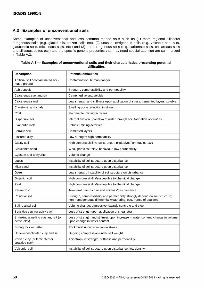
ISO/DIS 19901-8
58 © ISO 2013 – All rights reserved© ISO 2013 – All rights reserved
A.3 Examples of unconventional soils
Some examples of unconventional and less common marine soils such as (1) more regional siliceous terrigenous soils (e.g. glacial tills, frozen soils etc), (2) unusual terrigenous soils (e.g. volcanic ash, silts, glauconitic soils, micaceous soils, etc.) and (3) non-terrrigenous soils (e.g. carbonate soils, calcareous soils and siliceous oozes etc.) and the specific generic properties that may need special attention are summarized in Table A.3.
Table A.3 — Examples of unconventional soils and their characteristics presenting potential difficulties
Description Potential difficulties
Artificial soil / contaminated soil / made ground
Contamination; human danger
Ash deposit Strength, compressibility and permeability
Calcareous clay and silt Cemented layers; soluble
Calcareous sand Low strength and stiffness upon application of stress; cemented layers; soluble
Claystone and shale Swelling upon reduction in stress
Coal Flammable; mining activities
Dispersive soil Internal erosion upon flow of water through soil; formation of cavities
Evaporitic rock Soluble; mining activities
Ferrous soil Cemented layers
Fissured clay Low strength; high permeability
Gassy soil High compressibility; low strength; explosive; flammable; toxic
Glauconite sand Weak particles; "clay" behaviour; low permeability
Gypsum and anhydrite Volume change
Loess Instability of soil structure upon disturbance
Mica sand Instability of soil structure upon disturbance
Ooze Low strength, instability of soil structure on disturbance
Organic soil High compressibility/susceptible to chemical change
Peat High compressibility/susceptible to chemical change
Permafrost Temperature/structure and soil loss/gas presence
Residual soil Strength, compressibility and permeability strongly depend on soil structure; non-homogeneous differential weathering; occurrence of boulders
Saline alkali soil Volume change; aggressive towards concrete and steel
Sensitive clay (or quick clay) Loss of strength upon application of shear strain
Shrinking /swelling clay and silt (or active clay)
Loss of strength and stiffness upon increase in water content; change in volume upon change in water content
Strong rock or better Rock burst upon reduction in stress
Under-consolidated clay and silt Ongoing compression under self weight
Varved clay (or laminated or stratified clay)
Anisotropy in strength, stiffness and permeability
Volcanic soil Instability of soil structure upon disturbance; low density

ISO/DIS 19901-8
© ISO 2013 – All rights reserved© ISO 2013 – All rights reserved 59
Annex B (informative)
Deployment of investigation equipment
B.1 Deployment systems and precision of vertical depth measurements
B.1.1 General
This clause provides information on the various deployment systems currently in use and the main factors affecting the precision of vertical depth measurements using various types of soil investigation equipment currently in use. The information provided herein is for guidance purposes only, and is not exhaustive It is essential that a robust assessment of the key factors affecting vertical depth accuracy is made on a project by project basis.
Vertical depth measurement is largely influenced by the mode of operation of the investigation equipment. A summary of key issues that affect the precision of vertical depth measurements, for alternate types of equipment, is initially presented.
A summary of the common parameters that should be considered in the calculation of vertical depth accuracy is then presented.
B.1.2 Equipment deployment considerations
B.1.2.1 Vessel drilling systems
The precision of data point depth measurements for vessel drilling systems may be influenced by:
a) The performance of a vessel’s heave-compensation system in prevailing sea conditions.
An indication of the limiting sea state for which an estimated depth accuracy is likely to be exceeded should be provided.
b) The type of heave compensation reference system used.
‘Hard tie’ systems that utilize a template founded on the seafloor (as a reference against vessel heave) generally provide better drill-string stability than ‘non hard tie’ (active pressure) heave-compensation systems.
c) The water depth, and consequently the length of drill string deployed.
Longer drill strings are more susceptible to lateral displacements associated with undersea currents, and drill string ‘whipping’ (refer to Figure B.1 b).
d) The weight and elasticity of the drill pipe.
Heavier drill strings require stiffer heave-compensation systems. Stiffer systems are less sensitive to changes in seabed strength, and hence offer less feedback to the driller, particularly in weak soil layers.
e) The accuracy of the seafloor tagging exercise undertaken prior to the commencement of drilling.
This is a critical measurement that is used to accurately measure the water depth and account for current vessel draught, prior to commencement of drilling.
f) The accuracy of the echo sounder (or similar) equipment used to monitor tidal fluctuations – this is particularly important in regions that have high tidal fluctuations.

ISO/DIS 19901-8
60 © ISO 2013 – All rights reserved© ISO 2013 – All rights reserved
g) The accurate measurement of drill pipe and bottom hole assembly lengths.
h) The presence / absence of a seafloor template, and the capacity to accurately monitor its height relative to the seafloor.
i) The capacity of the vessel to maintain horizontal position in prevailing sea conditions;
Spatial deviation of the drill floor centre relative to the borehole centre will affect the estimated length of drill string down hole.
j) Push-in penetration accuracy of a deployed tool, relative to the bottom hole assembly.
The limiting surface environmental conditions, beyond which an agreed borehole depth accuracy class cannot be achieved within a reasonable level of confidence, should be clarified.
B.1.2.2 Seafloor-founded systems
Seafloor-founded systems are initially landed and stabilized on the seafloor, prior to acquiring data. This includes seafloor drilling systems (refer 6.1.3.3) and some seafloor-founded, non-drilling mode systems (6.1.2).
Factors affecting the precision of depth measurements for such systems can include:
the capacity of the system to land, level and fully stabilize itself on the seafloor prior to seabed investigation;
the method of isolating the seafloor-founded system from surface vessel movements;
1) Some systems are landed on the seabed and a catenary is formed in the umbilical prior to commencing investigation activities. Provided sufficient umbilical is paid out to accommodate vessel station-keeping requirements, this allows the seafloor-founded system to be fully isolated from vessel movements.
2) Alternatively, some systems are lowered to the seafloor on a constant-tension winch. Provided the surface environmental conditions remain within the dynamic operating capabilities of the winch, such systems can also provide effective isolation from surface vessel movements.
the accuracy of the drill-head position transducer;
the capacity of the system to measure, and monitor the height of the equipment relative to the seafloor (refer to Figure B.1 a);
the length, weight and elasticity of the drill string or push-rod assembly used to push the tool into the seabed;
the verticality of the tool within the borehole.
The limiting surface environmental conditions, beyond which an agreed borehole depth accuracy class cannot be achieved within a reasonable level of confidence, should be clarified.
B.1.2.3 Other non seafloor-founded systems
Other types of investigation equipment are not founded on the seafloor prior to the commencement of data acquisition (e.g. Gravity core or Kullenberg samplers). Such equipment typically remains partially to fully suspended on a non-heave compensated winch wire during the seabed interception phase of a deployment. The data acquisition process is typically of short duration only, thereafter the investigation tool is immediately recovered to the vessel deck.

ISO/DIS 19901-8
© ISO 2013 – All rights reserved© ISO 2013 – All rights reserved 61
Control of borehole depth accuracy can be poor for such systems, as the effects of vessel heave, in conjunction with the simplicity of the tool design, can impart uncontrolled, variable movement to the tool during the data acquisition process.
Depth measurements for these types of systems can be affected by:
vessel heave during interception and penetration of the tool into the seabed;
poor estimation of the penetration of the tool into the seabed - these types of equipment are generally not equipped with a seabed penetration estimation device;
the extent of penetration of the trigger plate into the seabed, prior to tool release (where applicable);
the weight of the lift cable and its elasticity;
the accuracy of the cable-payout meter;
the level of feedback provided to the winch operator when the system trips (where applicable);
the verticality of the tool during seabed penetration;
the horizontal offset of the tool relative to the deployment point on the vessel.
Estimation of data point depth accuracy for such systems is generally very difficult. For this reason the depth accuracy class should either:
1) be assumed to correspond to depth accuracy class z5 (>2 m as given in Table 1), or
2) calculations should alternatively be provided to justify a more precise depth accuracy class within the project specifications.
The limiting surface environmental conditions, beyond which an agreed depth accuracy class cannot be achieved, should be clarified.
B.1.3 Parameters affecting the precision of vertical depth measurements
B.1.3.1 Estimation of data point depth accuracy
Data acquired from a marine soil investigation programme are usually presented versus the estimated vertical depth below seafloor, where depth is normally quoted as a downwards positive value below seafloor. All depth measurements quoted will have an uncertainty associated with their measurement. As discussed in 6.2, the precision of data point depth measurements is an important parameter for the analysis of geotechnical results.
Three alternative approaches to depth measurement are possible:
a) measurements are made relative to a reference point at or close to the seafloor (refer to Figure B.1 a);
b) measurements are made relative to a reference point at or close to sea level (refer to Figure B.1 b); or
c) a combination of the above (refer to Figure B.1 b).
Values for hs, hd , hsf and dw, in Figure B.1 a) and b), are either estimated, or a direct physical measurement is undertaken. The basis for estimation may include experience or rule of thumb, visual observation against some scale reference, theoretical calculation, or via physical modelling.
Basic principles for physical measurement typically include one or more of the following:
tape measure;
mechanical distance sensor;

ISO/DIS 19901-8
62 © ISO 2013 – All rights reserved© ISO 2013 – All rights reserved
optical distance sensor;
acoustic distance sensor;
pressure sensor;
fluid flow sensor;
accelerometer;
inclinometer.
Supplementary and complementary measurements improve the confidence in the accuracy of a principal measurement. For example, for vessel-drilling systems the direct measurement of the seawater temperature profile can improve accuracy of values obtained by marine acoustic distance measurement (echo sounder or altimeter).
Each estimate or measurement will have an error. Estimates of these errors can be arithmetically added to obtain an overall estimate of the precision of borehole depth measurements. For complex systems this approach may be conservative, and more rigorous estimates of depth accuracy can be obtained via the separation of random and systematic errors, and the application of probabilistic principles.
Systematic errors affect the mean value of a measurement and, as opposed to random errors, are always in one direction. Calibration errors are an example of a systematic error. Random errors result in scatter if the measurement readings are plotted on an X-Y plot, and affect the variance of a measurement.
Some key parameters that may need to be considered in assessing the uncertainty of data point depth measurements are provided below. These parameters are provided as guidance only. A robust assessment of the key parameters affecting the estimated depth precision able to be achieved should always be made for each type of equipment deployed.
B.1.3.2 Identification of the true seafloor–water interface
The seafloor is commonly used as a reference datum for borehole depth measurements. The following factors should be considered in the estimation of seafloor level.
Seafloor elevation can change due to erosion or deposition events with time.
Deployed investigation equipment can partially displace very soft upper seabed materials during approach and touchdown.
The exact definition of the soil-water interface can be difficult to identify. Seafloor sensors, which identify the seafloor interface via measurement of upper seabed density or soil strength, have different threshold settings. Moreover, mechanical seafloor detection sensors may not detect a near-fluid upper seabed.
An acoustic distance sensor will typically record the highest point within its beam, which may not coincide with the point of investigation for an undulating or sloping seafloor.
B.1.3.3 Height of reference point above seafloor (hsf)
A seafloor frame can penetrate into the seabed upon touchdown. Measurement of seabed penetration is important for systems that measure borehole depth relative to the seafloor frame itself.
A seafloor frame may vertically displace and/or tilt as a result of forces generated during downhole investigation activities, forces applied by guide wires, heave compensated umbilical tethers, or eccentric loading of footings on seafloor slopes.

ISO/DIS 19901-8
© ISO 2013 – All rights reserved© ISO 2013 – All rights reserved 63
B.1.3.4 Depth below seafloor (z)
Estimation of tool-point depth is usually made via measurement of the length of drill string or push rods deployed downhole (Lstring, refer to Figure B.1), in relation to a fixed datum point located either at the seafloor (seafloor-founded systems) or at the drill floor (vessel-drilling systems). The precision of depth measurements can be affected by the following factors:
errors in estimated tool and drill string/push-rod measurements;
Whilst the actual length of tools can usually be measured within an acceptable tolerance; other factors that may need to be considered could include:
elastic shortening or lengthening of tools under varying thrust loads;
‘out-of-straightness’ of a drill string within a water column;
This may occur, for example, where slender drill strings are subjected to drag forces associated with sea currents.
non verticality of a drill string or push rods within the seabed;
thermal shortening or lengthening of drill string / push rods.
mechanical errors within thrust machines, for example, the slippage of gripping mechanisms used to either clamp, and/or thrust tools into the seabed.
electrical instrumentation errors, including:
hysteresis and non-linearity of displacement transducers;
measurement errors within inclinometers used to estimate the verticality of deployed tools;
Where sampling is undertaken, the assignment of sample loss within a sampling run is often based on engineering judgement. This may introduce additional uncertainty for data-point depth measurements. Further guidance on the issues of sample loss, and how this factor can affect the estimated depth range over which a sample has been acquired, is provided in 9.5.
B.1.3.5 Water depth (dw)
The precise measurement of water depth is particularly important for vessel-drilling systems. Water depth variations occur due to natural factors such as tides, currents, wind and barometric pressure. Some factors that can affect the precise measurement of water depth measurements may include:
variation in vessel draught with time, arising due to (for example) variations in seawater salinity and the quantity of fuel/water retained onboard. The position of a fixed echo sounder below the water surface is usually directly affected by vessel draught.
errors associated with the sounding of the seabed at the commencement of seafloor operations. A direct sounding of water depth by drill string can be achieved by fixing the drill pipe in a seafloor frame at the seafloor. The straightness and verticality of the drill pipe will depend on factors such as weight on hook in drill derrick, seawater current and position of the seafloor frame relative to the drill derrick. An underwater positioning system mounted on the seafloor frame can provide information about the relative position of the seafloor frame. Length variations in drill pipe are discussed in B.2.2.3.
variations in barometric pressure, seawater salinity, turbidity and temperature, which can affect water depth measured via pressure sensors at the seafloor.
B.1.3.6 Height of reference points above sea level (hs and hd)
For vessel-drilling systems, errors associated with the estimated height of reference points above sea level should also be considered.
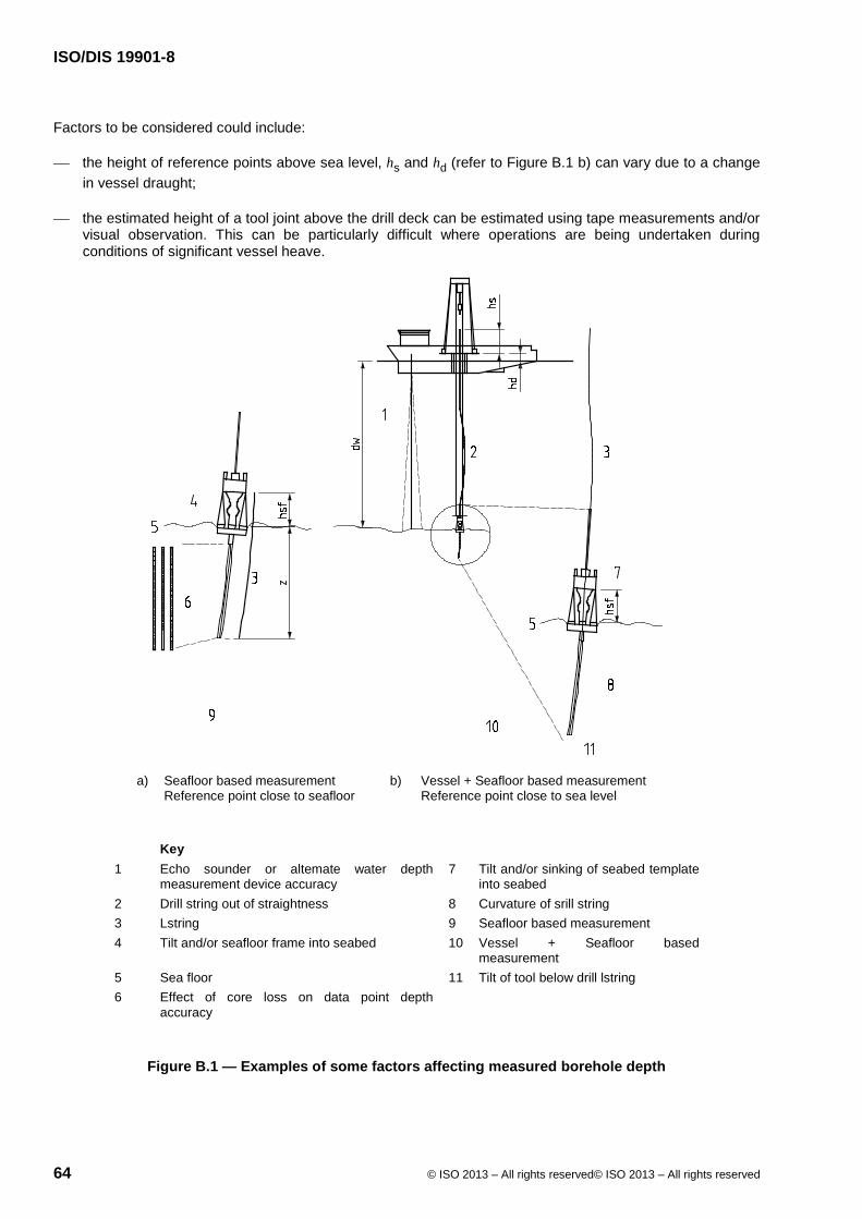
ISO/DIS 19901-8
64 © ISO 2013 – All rights reserved© ISO 2013 – All rights reserved
Factors to be considered could include:
the height of reference points above sea level, hs and hd (refer to Figure B.1 b) can vary due to a change in vessel draught;
the estimated height of a tool joint above the drill deck can be estimated using tape measurements and/or visual observation. This can be particularly difficult where operations are being undertaken during conditions of significant vessel heave.
a) Seafloor based measurement Reference point close to seafloor
b) Vessel + Seafloor based measurement Reference point close to sea level
Key 1 Echo sounder or altemate water depth
measurement device accuracy 7 Tilt and/or sinking of seabed template
into seabed 2 Drill string out of straightness 8 Curvature of srill string 3 Lstring 9 Seafloor based measurement 4 Tilt and/or seafloor frame into seabed 10 Vessel + Seafloor based
measurement 5 Sea floor 11 Tilt of tool below drill lstring 6 Effect of core loss on data point depth
accuracy
Figure B.1 — Examples of some factors affecting measured borehole depth

ISO/DIS 19901-8
© ISO 2013 – All rights reserved© ISO 2013 – All rights reserved 65
B.2 Minimization of seafloor disturbance effects
B.2.1 General
Most types of soil investigation systems interact with the seafloor in one way or another. Vessel-drilling systems with heave-compensation systems are reliant on seabed templates to provide a fixed reference against vessel heave, whilst seafloor-founded systems are directly founded on the seafloor prior to commencement of data acquisition.
Vessel-drilling systems normally deploy reference frames or templates to the seafloor prior to deployment of drill string. These devices may be used to provide reaction thrust as tools are pushed into the seabed, to enable hole re-entry where required, and to provide a vertical datum against which the vessel’s heave-compensation system is referenced. Seafloor-founded rigs are also located on the seafloor throughout the course of seabed investigations; these machines can impart variable loading to the seafloor as operations progress.
The landing of equipment on the seafloor prior to the start of the investigation can cause disturbance to the seabed. The transfer of equipment weight from the vessel to the seafloor can lead to artificial surcharging of the upper seabed. This can influence sample quality and in situ-measured test results. The geotechnical contractor should provide a clear description of the method of interaction of the proposed investigation equipment with the upper seabed.
The geotechnical designer should undertake an assessment of the interaction of the deployed investigation equipment with the seafloor, and whether this can have adversely affected the measured upper seabed properties during the course of the soil investigation. This can be particularly important where equipment is landed and operated on very soft seabed.
B.2.2 Measures to mitigate near seafloor soil disturbance
Whilst for some cases it is possible to apply approximate corrections to test data for seafloor disturbance effects, artificial seafloor disturbance should be minimized wherever possible. Disturbance can be minimized via the following techniques:
careful control of the rig during initial touchdown with the seafloor, to avoid rapid and uncontrolled impact;
This may include landing equipment at a time that coincides with a period of reduced vessel heave (for example between the passage of wave sets).
use of adequately sized ‘outrigger’ footings to transfer weight of the rig to the seafloor, well clear of the sampling/testing zone, at the point of initial rig landing on the seafloor;
maximization of the distance between the testing/sampling location and the area in which the weight of the machine is founded on the seabed;
minimization of the ‘on-bottom’ weight of the rig (and hence the load applied to the seafloor);
providing a means to adjust the height of the rig, as required, during seafloor operations;
maximization of the bearing area of the footings, to minimize applied bearing pressure;
use of foundation ‘skirts’ on a footing system, particularly where operating on very soft seabed.
B.3 Operations on steep seafloor gradients
B.3.1 General
Geotechnical investigations on steep and/or uneven seafloors is increasingly required.
Examples include:
ISO/DIS 19901-8
66 © ISO 2013 – All rights reserved© ISO 2013 – All rights reserved
pipeline route investigations that traverse from deepwater to continental shelves;
seabed investigations in areas of previous slope failures;
investigations in the vicinity of iceberg gouges;
investigations on rocky seafloors; and
operations within the vicinity of sand waves.
Operations on steep slopes present additional challenges to the safe operation of seabed investigation equipment. Information on seafloor slopes is normally obtained from the interpretation of geophysical site investigations or 3D seismic data. This information should be made available during the early stages of equipment selection, where steep slopes can be encountered.
The capabilities (and where appropriate the limitations) of the proposed geotechnical investigation equipment to effectively operate on the expected seafloor slopes is normally the responsibility of the geotechnical contractor.
The client should familiarize himself with the capabilities of the proposed investigation equipment, and the potential impacts on the quality of the acquired data. Special deployment methods, and/or specialist investigation equipment, may alternatively be selected to ensure accurate data is acquired in a safe manner.
B.3.2 Factors affecting equipment performance on steep slopes
The client should consider the following factors in assessing equipment performance on steep slopes:
the expected strength of the upper seabed at the proposed investigation sites, and whether the applied surcharge of the equipment can lead to seabed instability;
whether the operation of the equipment, resulting in vibrations, additional torsional or vertical loads could result in seabed instability;
whether the ‘out-of-levelness’ of the template will impede the passage and operation of the drill string;
the capacity to measure the height of the drill centre above the seafloor at the centre of the machine;
the local variability of the slope, and whether this is likely to affect the capacity of the system to land and remain stable during drilling operations.
A large proportion of equipment currently available for marine soil investigations can safely operate on seafloor slopes of up to 5°. Recent developments in drill ship and seafloor drilling technology have led to an enhanced capacity to operate on uniform slopes of up to 20°. It should be noted that these operating capabilities can reduce significantly on non-uniform (for example rocky) slopes.

ISO/DIS 19901-8
© ISO 2013 – All rights reserved© ISO 2013 – All rights reserved 67
Annex C (informative)
Drilling and logging
C.1 Drilling methods
C.1.1 General
A variety of drilling methods and equipment are available. This part of ISO 19901 primarily considers rotary drilling techniques. Guidance can be found in ISO/TS 22475-2 and ISO/TS 22475-3 for further definition of equipment and personnel for onshore/nearshore soil investigations (presented herein where relevant).
In rotary drilling, the rate of penetration (ROP) depends on a combination of the characteristics of the bit, the pressure and volume of flow of drilling fluid (mud pressure and mud flow), the normal force between the bit and the bottom of the borehole (weight on bit), and the characteristics of the material being cut. Depending on the objectives, the driller adjusts the combination of weight on bit, drill fluid pressure and flow, and drill fluid characteristics in order to advance the borehole.
When drilling from a floating vessel, cyclical variations in weight on bit (and hence soil disturbance) are induced by vertical motions at the drill floor. These motions are attenuated by employing a heave-compensation system. Appropriate equipment should be identified for the defined drilling objectives. Where optimal data quality is an objective, the hard-tie heave-compensation system offers a high performance option, particularly in softer soils.
Appropriate drilling equipment and methods should be identified for the defined drilling objectives. Within the two main modes of deployment (i.e. vessel-drilling mode, and seafloor-drilling mode), the typical types of rotary drilling are:
'open-hole’ or ‘core’ drilling;
'uncased’ or ‘cased’ drilling;
'riserless’ or ‘riser’ drilling.
C.1.2 Open-hole or core drilling
In rotary open-hole drilling, sampling and in situ testing are performed on undisturbed material ahead of the bit by pushing (and other means such as percussion) specialized wireline tools through the open centre of the bit.
In rotary core drilling, core samples are recovered either as cores typically 1,5 m to 3 m long, recovered by a drop-in wireline coring system, or as long continuous lengths of core typically 6 m or more, recovered by pulling the complete drill string out of the borehole to recover the core barrel. However, in the latter case, a re-entry system is needed in order to re-enter the existing borehole to advance to the next core interval.
The drilling technique adopted will largely be governed by the expected soil conditions, the requirement for sample quality, and required in situ testing. Open-hole drilling with sampling and testing by downhole tools is generally appropriate for uncemented formations, and for some weakly cemented soils or very weak rock formations (e.g. highly weathered chalk). Rotary core drilling is generally appropriate for cemented soils or rock formations, and can also be a good alternative in hard boulder clays, especially if recovery is more important than sample quality.
In some cases, a combination of the two techniques can be employed, with three different coring systems and procedures, given below, that may be adopted:

ISO/DIS 19901-8
68 © ISO 2013 – All rights reserved© ISO 2013 – All rights reserved
a) Pull out the open-hole drill string completely and run in a rotary coring drill string. This approach requires additional pipe handling, but maximizes core sample diameter and ensures that the most appropriate drill bit is always used for the formation encountered.
b) Pull the open-hole drill string back a short distance from the bottom of hole, then run a coring drill string through the centre of the open-hole string (termed ‘piggy-back coring’). This approach requires some additional pipe handling, possibly an additional top drive unit, and the sample diameter is reduced, but borehole integrity is assured and the most appropriate drill bit for the formation encountered can be used. This mode of operation requires a seafloor frame to be clamped onto the drill string in order to eliminate the open hole drill string for heaving within the borehole due to the motion of the vessel.
c) Drop a wireline core barrel through the open-hole drill string to latch into a specialized open-hole drilling BHA. This approach saves pulling or running any additional drill string, but requires continued use of the open-hole drill bit, which may be less appropriate for the formation to be cored and can result in poorer quality core sample and/or reduced recovery.
C.1.3 Uncased or cased drilling
Most marine soil investigations are performed using equipment in uncased, open-hole rotary drilling mode, where a single tubular (the drill string) runs from the drilling platform.
At sites where borehole stability can be an issue (such as excess pore pressure regimes, or very deep boreholes), or where project-specific objectives demand (e.g. ‘piggy-back coring’), it may be necessary to install one or more casing strings prior to completing the borehole. Casings may be either specialized casing tubulars run separately, or drill pipes doubling as casing once a certain depth (or other criteria) has been achieved. Multiple concentric casing strings, reducing in diameter as the borehole advances, may be employed and specialized handling equipment and procedures may be required.
C.1.4 Riserless or riser drilling
Most marine soil investigations are performed in riserless drilling mode, where drill fluids and cuttings flow between the annulus of the borehole and the outside diameter of the drill pipe and end either at the top of the borehole (i.e. at seafloor) or at the top of the casing string. With riserless drilling (also termed ‘total loss drilling’ or ‘drilling with fluid returns to seafloor’), all drilling fluid and cuttings exit the borehole in a plume which is either dispersed by sea bottom currents, or from which cuttings settle out of suspension to form a mound in the vicinity of the borehole.
With riser drilling, a tubular casing extends from the borehole back up to the floating vessel or platform. This allows the recovery of drilling fluid and cuttings, either for recirculation, for retention of the fluids and cuttings (e.g. in areas where zero discharge to sea is required), or to sample the cuttings. Riser drilling requires specialized handling and processing equipment and procedures (see ISO 22475-1). In particular, care is needed to ensure that the elevated hydraulic pressure exerted on the borehole walls by the hydraulic head of drilling fluids between the water surface and the riser top does not lead to hydraulic fracture of the formation, which can lead to loss of drilling fluid into the formation and can compromise borehole stability or sample quality.
C.2 Selection of drilling equipment and procedures
C.2.1 Drilling equipment suitability considerations
In order to assess the suitability of a particular drilling spread of equipment for a given set of project-specific requirements, details of the equipment to be provided should include the following:
operating platform description (i.e. floating or fixed platform, moonpool or over-side deployment, submersible drill rig) with nominal operating limits (i.e. sea/tide/current/wind);
drilling system capacity, with drill mast/derrick height, weight capacity under the power swivel (i.e. maximum mass of drill string including drill collars and BHA), and details of draw works heave-

ISO/DIS 19901-8
© ISO 2013 – All rights reserved© ISO 2013 – All rights reserved 69
compensation system (type, maximum capacity, full stroke length and usable stroke length) if in floating vessel mode;
specification of drill pipes and drill string handling system, with maximum length of drill string that can be handled and maximum pipe stand length;
description of drill bits carried onboard, and rotary coring system (if any);
details of the seafloor frame, and of its heave-compensation system (type, maximum capacity, full stroke length, usable stroke length);
mud system details, with mud pump(s), mixing capacity, number and volume of mud tanks, maximum pumping rate;
drilling parameter logging system (i.e. automated or manual, parameters logged, reporting format and system limitations);
manning levels required on the drill floor, with location of controls for drilling and wireline downhole equipment, pipe and wireline tool handling systems.
Table C.1 offers guidance on drilling equipment characteristics relevant to particular project requirements. It can be used to help identify appropriate or inappropriate equipment.
Table C.1 — Drilling equipment selection considerations
Priority Project-specific requirements
Principal drilling equipment selection considerations
1 Water depth and sea conditions
Seafloor drilling/vessel drilling/availability/hook capacity/power/ heave compensation
2 Soil conditions Open-hole/rotary coring/ uncased/ cased/riserless/ riser/power
3 In situ testing and sampling Open-hole (or combination)/seafloor reaction frame/heave compensation
4 Borehole depth Uncased/cased/riserless/riser/power
5 Drilling hazards Uncased/cased/riserless/riser/pilot hole/specialized equipment
6 HSE and extreme working environment Specialized equipment (minimized manual drill floor interventions)
7 Environmental discharge Riserless/ riser
Modifier Optimized data quality Accurate heave compensation/ seafloor reaction frame
Modifier Optimized data recovery Working height (maximum length of downhole tool that can be handled)
Modifier Optimized rate of progress Power/mud flow
C.2.2 Drill bit selection
The selection of drill bit should be made based on the expected soil conditions, required sampling and/or in situ testing techniques, and whether optimal sample quality or maximum rate of penetration (ROP) is required.
Where sampling or testing is required, an open-centred bit (‘core bit’) is used in open-hole drilling mode. For drilling without sampling or testing, a close-centred destructive drilling bit can offer greater ROP. Also available are drop-in ‘centre’ bits which latch into the BHA to convert an open-centred bit into a close-centred bit, and can subsequently be recovered by wireline overshot.
For open-hole drilling in uncemented marine soils, a drag bit is likely to be the preferred solution. The drag bit is particularly appropriate where it is expected to encounter clay strata (which can have a tendency to ‘ball’ and block the discharge ports of other designs of bit, which can lead to bit damage and/or significantly
ISO/DIS 19901-8
70 © ISO 2013 – All rights reserved© ISO 2013 – All rights reserved
reduced ROP). For other ground conditions (principally rock), ISO 22475-1 provides additional guidance regarding bit selection.
The following factors should be considered for drill bit selection:
range of bits for the possible soil conditions, drilling problems and hazards that could be encountered;
criteria for change of drill bit;
positioning of drilling fluid discharge ports and bit geometry (i.e. the bit should be balanced to minimize the tendency of the borehole to deviate from the axis).
C.2.3 Drilling fluid
The function of the drilling fluid is twofold: to carry drill cuttings away from the cutting face, and to prevent the drill bit from overheating. However, depending upon its specific characteristics, the fluid can also serve a number of other functions:
borehole advancement, i.e. cutting soil ahead of the bit by hydraulic action;
borehole stability, i.e. formation of a stable ‘cake’ around the wellbore thereby helping prevent cave-in of the borehole walls, particularly in loose non-cohesive or over-pressured formations;
prevention of drill cuttings from settling back to the bottom of the borehole while pumping is stopped, for example when running a sampling or in situ testing tool;
control of hydrostatic pressure in the borehole.
Drilling fluids are typically based on seawater (or fresh water), and in many cases water alone is sufficient, provided the mud system is able to deliver adequate flow rate and pressure. When defining the drilling fluid to be used, consideration should be given to the potential for adverse chemical interactions of the drilling fluid (including seawater) on the soil, e.g. low salinity seawater with high salinity soil.
If the drilling fluid is required to perform additional functions, then one or more additives may be included to give the necessary characteristics, e.g. the addition of barite to give a heavy ‘kill mud’ suitable for controlling a shallow gas event. Additives can be supplied in liquid or powder form, and specific mixing procedures should be followed (with due regard to HSE considerations). It may be necessary to periodically test samples of the mixed fluid to ensure that the desired consistency and viscosity characteristics are maintained across multiple batches.
For complex borehole constructions, or in difficult soil conditions, it is recommended to seek advice from experts regarding design of an appropriate drilling fluid programme.
C.3 Drilling operations plan
The drilling operations plan describes the process of considering and documenting the drilling activities relating to the soil investigation. The drilling operation plan may be documented in a stand-alone document (suitable for daily reference by the drilling crew), or may be part of the soil investigation execution plan in the PEP.
For the range of possible soil conditions, the drilling operations plan should describe the full sequence of activities and contingencies for each borehole, from initiation to completion. It should consist of the following basic components:
drilling equipment and operational details;
borehole construction plan, describing the sequence of borehole construction (with drill string details and drill bit selection), identification of possible drilling problems, borehole abandonment procedures and
ISO/DIS 19901-8
© ISO 2013 – All rights reserved© ISO 2013 – All rights reserved 71
grouting procedures (if required), and contingencies or remediation options (e.g. in the event of stuck string or tool lost in the borehole);
mud plan, with the drilling fluid solution adopted and criteria for change of fluids;
requirements for recording drilling parameters (as appropriate);
sampling and in situ testing schedule and procedures;
shallow gas plan (where relevant, see C.4);
grouting plan (if required), with the grouting fluid/additives selected, grouting procedures, and requirements for grout testing (i.e. grout cube crush tests and acceptance criteria).
C.4 Shallow gas
C.4.1 General
Shallow gas can pose a significant hazard to drilling operations, and all efforts should be made to avoid release of gas into the sea and atmosphere. In order to minimize both the likelihood and consequences of such a release, a site specific assessment should be undertaken which should include the following:
‘hazard assessment’ for the specific location and planned activities, to identify the likelihood of encountering gas during the soil investigation;
’risk assessment’, for the geotechnical vessel/platform, to identify zones of high, intermediate and low risk with due consideration of the consequences of gas release and mitigating measures.
C.4.2 Hazard assessment for specific locations
The site-specific hazard assessment is usually performed by the client, but it should be incumbent upon the soil investigation contractor to ensure that the hazard assessment conclusions are aligned with his own procedures and that the risks (probability × consequence) that the hazards pose to the planned operations are assessed properly.
The hazard assessment would typically consider the following:
regional geology/desk study;
site-specific geophysics (considering type, quality, resolution and timing of the data acquisition);
potential for changes since geophysical data acquisition (e.g. due to well-drilling activity);
potential depth, pressure and volume of shallow gas;
alternative sources of free gas, and gas characteristics (composition, toxicity, flammability, density);
planned soil investigation activities, e.g. seafloor-mode operations, borehole drilling/sampling/in situ testing operations, pilot-hole drilling, distance to production infrastructure.
There are three possible outcomes of the hazard assessment for a specific location as listed below:
a) low probability of encountering gas;
b) intermediate probability of encountering gas;
c) high probability of encountering gas.

ISO/DIS 19901-8
72 © ISO 2013 – All rights reserved© ISO 2013 – All rights reserved
C.4.3 Risk assessment and gas procedures
C.4.3.1 Depending upon the hazard assessment outcome, all areas of the geotechnical drilling vessel/platform should be assessed, i.e. specific areas of potential gas release or accumulation identified, and area classification layouts for the vessel developed (guidance on hazardous area classification for drilling facilities is given in IEC 61892-7).
Typically, the risk assessment should consider
specific activities, such as riser/riserless drilling, adding/tripping pipe, sampling/in situ testing, potential sources of ignition, soil sample handling, entry to confined spaces, etc.;
consequences, e.g. loss of vessel buoyancy, vessel flooding due to rolling water, blowout, fire/explosion, poisoning (gas toxicity), etc.;
proportional mitigating measures.
C.4.3.2 Even for a low probability of encountering gas, it is prudent to consider the implementation of residual risk mitigation measures. See C.4.3.3 regarding mitigation measures which should be considered.
C.4.3.3 In areas with intermediate probability of encountering shallow gas or free gas, special procedures should include the following:
safety meetings of all crew members;
review of the duty watch/ chain of command in emergency gas drill;
conduct of move-off exercise;
no hot work or smoking on deck;
gas detectors (in the moonpool and in the derrick) and gas alarm;
wind and current meters to ensure vessel is positioned optimally with respect to the wind and current to minimize accumulation of gas on deck;
general look-out or dedicated bridge watch for bubbles surfacing in the vicinity of the vessel/platform;
investigate the possibility of having heavy ‘kill mud’ available (together with rapid switch-in and high capacity pumping system).
consider drilling a dedicated pilot-hole during daylight hours with a non-return valve in the lower part of the drill string and no running of downhole tools,
as a precaution against gas through the drill string, maintain a safety valve on top of the power swivel while using wireline-operated downhole tools,
as a precaution against gas outside the drill string, maintain offset between the drilling vessel and the borehole (based on wind and current conditions). Typically, soil investigation operations can continue with horizontal offsets around 5 % to10 % of water depth,
suspend all non-essential crane operations,
monitor penetration and pump pressure consistently.
If a shallow gas risk is identified, specialized training can be required not only for the drill crew but also for all crew members, consisting of a course on shallow gas preparedness (drill crew), shallow gas induction (all crew), and regular gas alarm drills (all crew).

ISO/DIS 19901-8
© ISO 2013 – All rights reserved© ISO 2013 – All rights reserved 73
C.4.3.4 In areas with high probability of encountering shallow gas, further precautions such as the following are recommended in addition to those in C.4.3.3:
non-return valve in the lower part of the drill string while drilling and pulling pipe;
TV camera and/or sonar mounted on the seafloor frame or ROV;
pulling out of the soil the sampling/testing tool by lifting drill string while the downhole tool is latched into the BHA (with special attention to the swabbing effect when pulling tools out of the soil;
in situ gas measuring system, in order to ensure early warning before the gas-charged layer is penetrated;
Depending upon the source, characteristics and severity of the gas hazard, and on the drilling equipment employed, a variety of additional equipment can be considered for use in mitigation.
Examples of such equipment are:
gas diverter on top drive unit;
shear rams;
mud valve;
wireline non-return valve in BHA;
annular preventer on top drive (allowing the wellbore to be sealed with wireline tools in the hole);
isolated moonpool chamber (with fresh air duct or HVAC system);
zoned drill floor equipment;
automatic shut-off for unzoned ship’s equipment on gas alarm;
personal portable gas detectors;
breathing apparatus;
intrinsically safe communications system.
C.5 Borehole geophysical logging
C.5.1 General
The geophysical logging of a borehole can provide an invaluable additional data set, and a variety of different parameters can be measured, recorded or inferred. When defining a suitable geophysical logging scope of work, some of the following aspects should be considered:
a) required measurement types;
b) minimum number of measurements per logged depth section;
c) required sequence, direction and rate of travel for logging;
d) accuracy class for depth below seafloor, which should be given in project specifications according to Clause 6;
e) required correlations between measurements;
f) number of tools or length of logging section per run;
ISO/DIS 19901-8
74 © ISO 2013 – All rights reserved© ISO 2013 – All rights reserved
g) length of rat hole drilled;
h) whether a compensated logging line is required.
If a radiation-type logging system is planned, a qualified radiation protection supervisor should be onboard the soil investigation vessel, and operational procedures for these tools should be established to address the following:
handling of radioactive sources in accordance with applicable regulations;
heave compensation of wireline tools;
contingency procedures to recover tools lost in the borehole or on the seafloor;
contingency procedures in the event that it is impossible to recover a radioactive tool from the borehole (typically grouting).
C.5.2 Reporting of results
The report on logging results should include as a minimum:
characteristics of the borehole geophysical logging system;
details of borehole conditions according to Clause 7;
open-hole logging versus in-pipe logging;
sequence, direction and rate of travel of the logging probes in the borehole;
accuracy class for depth below seafloor;
presentation of results;
definitions, formulae, assumptions and limitations of derived parameter values and applied correlations between measurements.

ISO/DIS 19901-8
© ISO 2013 – All rights reserved© ISO 2013 – All rights reserved 75
Annex D (informative)
In situ testing
D.1 CPTU/CPT equipment and procedures
Guidance on the CPTU/CPT procedure and interpretation can be found in Lunne et al. (1997) and Schnaid (2009).
Cone penetrometers with dimensions outside the standard range may be used for special purposes, e.g. an enlarged cone for increasing accuracy of the measurements in very soft clay. In such cases, it should be reported that non-standard equipment has been used. In Tumay et al. (1998) and Watson and Humpheson (2005) it is shown that, for some penetrometers, the measured cone resistance, qc, can increase when carrying out a CPT/CPTU with a smaller cone diameter.
Empirical correlations developed for standard size penetrometers may not be applicable/valid for penetrometers outside the allowable range, and should be used with caution in the absence of parallel testing using standard size equipment.
In some cases, important information can be obtained by carrying out tests at non-standard rates. If such tests are carried out, results should be clearly marked noting that non-standard rates have been adopted.
As covered in 8.3.4 of the main text it is important to correct cone resistance for pore pressure effects. It is also possible to correct the sleeve friction for pore pressure effects if pore pressures at top and bottom the sleeve have been measured or can be assumed.
The corrected sleeve friction can be determined from:
( )s
st3sb2st A
AuAuff
×−×−=
where
ft is the corrected sleeve friction, in MPa;
fs is the measured sleeve friction, in MPa;
As is the area of friction sleeve, in mm²;
Asb is the cross sectional area of the bottom of the friction sleeve, in mm²;
Ast is the cross sectional area of the top of the friction sleeve, in mm²;
u2 is the pore pressure measured between the friction sleeve and the cone, in MPa;
u3 is the pore pressure measured above the friction sleeve, in MPa.
This correction requires values of u2 and u3 and these parameters should preferably both be measured if this correction is to be made.
NOTE u3 can be estimated from u2 using correlations given by Lunne et al.(1997)
These corrections are most important in fine-grained soils where the excess pore pressure during penetration can be significant. It is recommended to use corrected values of the test results for interpretation and classification purposes.
ISO/DIS 19901-8
76 © ISO 2013 – All rights reserved© ISO 2013 – All rights reserved
D.2 Documentation of reference readings for CPTU/CPTs
D.2.1 CPTU/CPT, ball and T-bar tests in non-drilling mode
The following recommended procedure is applicable in non-drilling mode. Figure D.1 shows an example of results obtained during a CPTU in non-drilling mode.
With reference to Figure D.1, the test can be divided into the following time stages:
Stage 1-2 Initial acquisition of reference readings from all sensors at deck level. The reference readings should be recorded once the output signals from the sensors are stable. This should be undertaken with the cone penetrometer and rods at a temperature as close as possible to the seafloor temperature.
Stage 3-4 Recording of all reference readings once the probe is located at (but not in contact with) seafloor. The reference readings should be recorded once the output signals from the sensors are stable.
Stage 4-5 Penetration into seabed.
Stage 5-6 Extraction of the probe until it is located again at (but not in contact with) seafloor.
Stage 6-7 Recording of reference readings of all sensors at the seafloor. The reference readings should be taken once the output signals from the sensors are stable.
Stage 7-8 Recovery of the push frame and probe to deck level. Visual inspection of the probe for any damage, soil adhesion to probe, damaged or dirty seals, etc.
Stage 8-9 Taking final reference readings of all sensors at deck level. The probe should remain in a vertical orientation during these measurements. The reference readings should be recorded once the output signals from the sensors are stable.
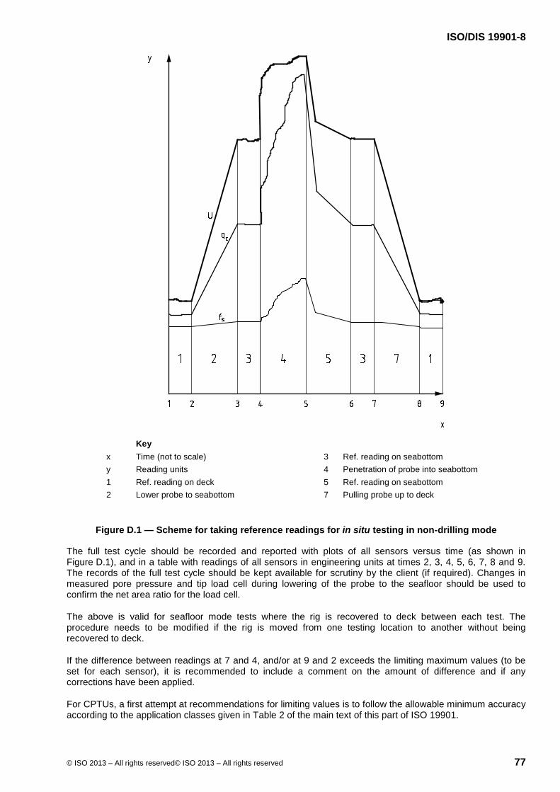
ISO/DIS 19901-8
© ISO 2013 – All rights reserved© ISO 2013 – All rights reserved 77
Key x Time (not to scale) 3 Ref. reading on seabottom y Reading units 4 Penetration of probe into seabottom 1 Ref. reading on deck 5 Ref. reading on seabottom 2 Lower probe to seabottom 7 Pulling probe up to deck
Figure D.1 — Scheme for taking reference readings for in situ testing in non-drilling mode
The full test cycle should be recorded and reported with plots of all sensors versus time (as shown in Figure D.1), and in a table with readings of all sensors in engineering units at times 2, 3, 4, 5, 6, 7, 8 and 9. The records of the full test cycle should be kept available for scrutiny by the client (if required). Changes in measured pore pressure and tip load cell during lowering of the probe to the seafloor should be used to confirm the net area ratio for the load cell.
The above is valid for seafloor mode tests where the rig is recovered to deck between each test. The procedure needs to be modified if the rig is moved from one testing location to another without being recovered to deck.
If the difference between readings at 7 and 4, and/or at 9 and 2 exceeds the limiting maximum values (to be set for each sensor), it is recommended to include a comment on the amount of difference and if any corrections have been applied.
For CPTUs, a first attempt at recommendations for limiting values is to follow the allowable minimum accuracy according to the application classes given in Table 2 of the main text of this part of ISO 19901.

ISO/DIS 19901-8
78 © ISO 2013 – All rights reserved© ISO 2013 – All rights reserved
Although Figure D.1 shows the results of a CPT/CPTU, the same principle applies for ball or T-bar tests.
D.2.2 CPTU/CPT and ball tests in drilling mode with seafloor-founded rig
For tests in drilling mode with a seafloor-founded rig, which remains at seafloor level throughout the completion of the borehole, in situ test tools are remotely switched on, stabilized and zeroed remotely at the seafloor prior to deployment into the borehole.
With reference to time stages shown in Figure D.2, the following procedure is recommended for CPT/CPTU in drilling mode:
Stage 1-2 Probe is extracted from the tool magazine, activated and loaded into the drill centre; initial zero readings are taken with probe located at a fixed level above the seafloor (within the confines of the machine);
Stage 2-3 Probe is lowered to seafloor (new borehole) or to bottom of borehole;
Stage 3-4 Penetration is commenced within undisturbed soil to required test depth or subsequent tool refusal;
Stage 4-5 Probe is recovered to final zeroes position and zeroes taken (same elevation as per Stage 1-2);
Stage 5-6 Probe is returned to the tool magazine and switched off.
A comparison is then made between the following measurements:
a) initial zero readings (Stage 1-2) taken between current and previous tests, provided the same probe was deployed in the borehole in subsequent tests;
b) final zero readings taken for each test (Stage 4-5).
Recommended limiting variations in outputs are in accordance with D.2.1.

ISO/DIS 19901-8
© ISO 2013 – All rights reserved© ISO 2013 – All rights reserved 79
Key x Time (not to scale) 5 Ref. Reading tool just above seabed y Absolute transducer outputs 6 Probe relative position 1 Ref. Reading tool just above seabed 7 Open borehole 2 Lower probe to seabed and down borehole 8 Borehole bottom 3 Penetration of the probe into soil 9 Maximum probe penetration 4 Extraction of the probe to just above seabed
Figure D.2 — Scheme for taking reference readings for in situ testing in drilling mode
Although Figure D.2 shows the results of a CPT/CPTU, the same principle applies for ball or T-bar tests.
D.2.3 CPTU/CPT and ball tests in drilling mode with surface vessel/platform
Deck-to-deck recording is recommended for cone penetration tests (CPT/CPTU), T-bar tests and ball penetrometer tests undertaken in classic vessel-based drilling mode. Reference values should be taken at deck level. Data processing of recorded measurements should consider
1) taking sensor offset values at the time of latching of the tool in the bottomhole assembly, and
2) calculating theoretical offset values from fluid pressure derived from combined water depth and depth of sensor below seafloor.

ISO/DIS 19901-8
80 © ISO 2013 – All rights reserved© ISO 2013 – All rights reserved
Methods 1) and 2) usually result in offset values that are very close to each other. Substantial differences between the two methods should be clarified where necessary to meet selected target uncertainties.
Technical reasons for differences between results from Methods 1) and 2) include:
uncertainty margin for the effect of the hydrostatic fluid pressure on the sensor readings (Methods 1 + 2);
fluid pressure in the gap of the penetrometer not acting on the full theoretical cross-sectional area(s) (Methods 1 + 2);
inadequate borehole cleanliness, causing the probe and the sensor(s) to be in contact with the soil at the time of latching of the tool in the bottomhole assembly (Method 1);
drilling fluid unit weight differing from that of the seawater and the pore fluid (Method 1);
suspended drill cuttings affecting the unit weight of the introduced drilling fluid (Method 1);
significant hydraulic resistance (surging) in the annulus between the drill pipe and the surrounding soil (Method 1);
uncertainty margin for the calculated fluid pressure derived from the combined water depth and depth of sensor below seafloor (Method 2).
D.3 Seismic cone tests (SCPTU/SCPT)
The SCPTU test can also be used for measurement of compression wave velocity vp, for example for the performance of vertical seismic profiles (VSP) in geotechnical boreholes. In this case, the seismic source can be a water/air gun deployed over the side of the drilling vessel/platform [see Nauroy et al. (1998)].
D.4 Field vane tests (FVT)
In some cases, shearing rates different from standard rates may be adopted. If such tests are carried out, results should be clearly marked noting that non-standard rates have been adopted. Guidance on effects of varying shearing rates is given in Peuchen and Mayne (2007).
D.5 Other in situ tests
Guidance and examples of the application of other available in situ tests are given in:
Orange et al. (2005) for needle-like CPT, for pore pressure measurement and for performance of dissipation tests;
Wright and Tan (1991) for hydraulic fracture testing;
Sultan et al. (2007) for specially adapted CPT tests for in situ measurement of the velocity of shear waves and for the detection of sediments containing gas or gas hydrates.
Lunne et al. (1997), Schaid (2009) and Peuchen and Rapp (2007) present overviews.

ISO/DIS 19901-8
© ISO 2013 – All rights reserved© ISO 2013 – All rights reserved 81
Annex E (informative)
Sampling
E.1 Selection of sampling tools
E.1.1 General
The information in this annex describes the available tools typically used in a marine soil investigation, and comments on their geometry, suitability and the potential sample quality that can be achieved. It further provides guidance as to what information the contractor should provide on the sampling tool systems.
E.1.2 Drilling mode samplers (vessel-based and seafloor-based)
E.1.2.1 Samplers and their suitability to different soils
Table E.1 below provides guidance on samplers deployed downhole via drilling mode. This includes the nominal range of penetration into the soil, sampler diameter and suitability in different soil types. The sampler geometries given are industry standard, although other dimensions exist and can sometimes be preferable.
Table E.1 is a general guide to the suitability of typical samplers to particular soil types and provides information on typical ranges of penetration and sample diameters that can be expected. The table footnotes a) to f) indicate factors which can contribute to a reduction in the quality of the sample recovered (see Table 6, valid for very soft to soft clay).

ISO/DIS 19901-8
82 © ISO 2013 – All rights reserved© ISO 2013 – All rights reserved
Table E.1 — Samplers deployed downhole via drilling mode
Sampler type
Ran
ge o
f pe
netr
atio
n m
Sam
ple
diam
eter
a
mm
Suitability for marine soil types
Very
sof
t to
soft
clay
Stiff
to v
ery
stiff
cla
y
Har
d bo
ulde
r cl
ay
Loos
e to
m
ediu
m
dens
e sa
nd/s
ilt
Den
se
silt/
sand
(n/a
gr
avel
)
Wea
kly
cem
ente
d so
ils a
nd
rock
Piston sampler
1 to 2+ 44 to 75 A A to B n/a Ab n/a n/a
Push sampler, thin-walled
1 to 2 75 A A to B n/a Ab B to Cc B to Cc
Push sampler, thick-walled
0,5 to 1 40 to 70 D
D
Bd
D Ce Ce
Rotary core sampler
1 to 3 44 to 101f n/a B to C
A
n/a n/a Ab
Percussion/vibratory sampler
3 to 5 50 to 97 D B to C B to C B to C A to C D
Hammer sampler
0,1 to 1 40 to 60 D D B D A to Cg B to C
NOTE 1 Capital letters denote “suitability class” where: A: highly suitable/recommended, B: moderately suitable, C: slightly suitable, D: unsuitable, and n/a: not applicable NOTE 2 Penetration refers to depth below base of borehole.
a Industry practice. Larger diameter would normally provide higher sample quality but has to be considered in relation to sample length and sampling technique. b Loss of sample is an issue and can necessitate use of alternative samplers with core catcher. c Only short samples possible, and the leading edge of the cutting shoe is prone to buckling. d Limited penetration and no recovery is likely where gravel and/or cobbles are encountered. e Offers a reduced likelihood that sufficient penetration and recovery will be achieved. f Larger diameters are preferable. g May be the only way to obtain some recovery.

ISO/DIS 19901-8
© ISO 2013 – All rights reserved© ISO 2013 – All rights reserved 83
E.1.2.2 Information on drilling mode samplers
Table E.2 below contains a description of the information needed for samplers in drilling mode, depending on the scope of work and what is provided.
Table E.2 —Required information for drilling-mode samplers (downhole samplers)
Sampler type Diameter and length of sample
System description including driving
mechanism
Maximum driving force available
Method for measuring penetration
Piston sampler √ √ √ √
Push sampler, thin-walled
√ √ √ √
Push sampler, thick-walled
√ √ √ √
Rotary core sampler √ Incl. bit type and dimensions
Torque and static push √
Percussion/vibratory sampler
√ √ Frequency and energy √
Hammer sampler √ √ Hammer mass, fall height and winch characteristics
√
A hammer sampler should not be used as an SPT tool for estimating relative density of sands from number of blows.
NOTE √ denotes information to be provided.
E.1.2.3 Sample tube geometry and dimensions
The following information should be considered for sampling tubes.
a) The thickness of the tube wall should be chosen so that the tube resists distortion when pushed into the soil.
b) The thin-walled tube samplers used (which are commonly used for push and piston sampling, and typically have outer and inner diameters of approximately Do = 76 mm and Di = 72 mm respectively) should meet the following requirements, which apply by analogy to samplers with other internal diameters:
The edge taper angle should not exceed 5°.
Taper angles between 5° and 15° and area ratios up to 25 % may only be used if it is demonstrated that the quality class is not affected.
The area ratio, CA (CA = (Do2 – Di
2)/Do2) should be less than 15 %.
For tube samplers with CA exceeding 15 %, the angle of the cutting edge should decrease as the wall thickness increases.
Inside clearance (Ci = (Di − Dc)/Dc, where Dc is internal diameter of the cutting shoe) is typically in the range 0 % to 1 % and preferably less than 0,5 %. Alternative systems may be acceptable, such as piston samplers with sharp edge and internal liners. When assessing the inside clearance, the worst case of manufacturing tolerances should be applied.
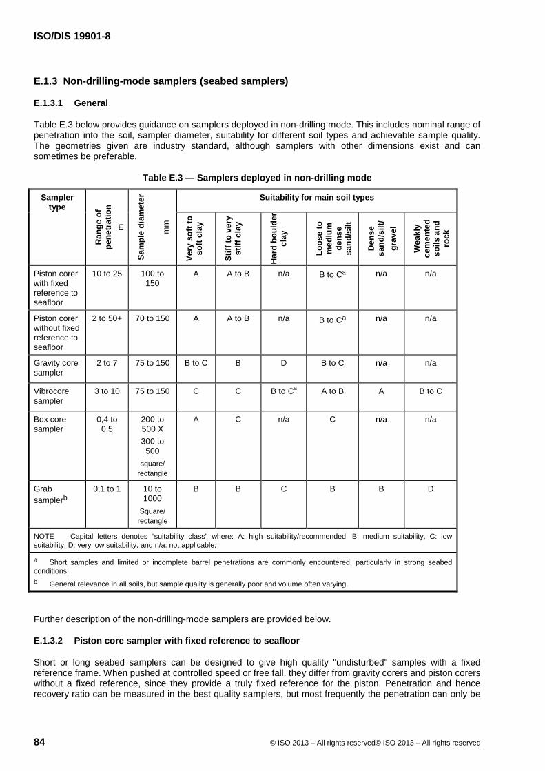
ISO/DIS 19901-8
84 © ISO 2013 – All rights reserved© ISO 2013 – All rights reserved
E.1.3 Non-drilling-mode samplers (seabed samplers)
E.1.3.1 General
Table E.3 below provides guidance on samplers deployed in non-drilling mode. This includes nominal range of penetration into the soil, sampler diameter, suitability for different soil types and achievable sample quality. The geometries given are industry standard, although samplers with other dimensions exist and can sometimes be preferable.
Table E.3 — Samplers deployed in non-drilling mode
Sampler type
Ran
ge o
f pe
netr
atio
n m
Sam
ple
diam
eter
mm
Suitability for main soil types Ve
ry s
oft t
o so
ft cl
ay
Stiff
to v
ery
stiff
cla
y
Har
d bo
ulde
r cl
ay
Loos
e to
m
ediu
m
dens
e sa
nd/s
ilt
Den
se
sand
/silt
/ gr
avel
Wea
kly
cem
ente
d so
ils a
nd
rock
Piston corer with fixed reference to seafloor
10 to 25 100 to 150
A
A to B
n/a B to Ca n/a n/a
Piston corer without fixed reference to seafloor
2 to 50+ 70 to 150 A
A to B
n/a B to Ca n/a n/a
Gravity core sampler
2 to 7 75 to 150 B to C
B
D
B to C n/a n/a
Vibrocore sampler
3 to 10 75 to 150 C
C
B to Ca
A to B A B to C
Box core sampler
0,4 to 0,5
200 to 500 X 300 to
500 square/
rectangle
A
C
n/a C n/a n/a
Grab samplerb
0,1 to 1 10 to 1000
Square/ rectangle
B B C B B D
NOTE Capital letters denotes “suitability class” where: A: high suitability/recommended, B: medium suitability, C: low suitability, D: very low suitability, and n/a: not applicable;
a Short samples and limited or incomplete barrel penetrations are commonly encountered, particularly in strong seabed conditions. b General relevance in all soils, but sample quality is generally poor and volume often varying.
Further description of the non-drilling-mode samplers are provided below.
E.1.3.2 Piston core sampler with fixed reference to seafloor
Short or long seabed samplers can be designed to give high quality "undisturbed" samples with a fixed reference frame. When pushed at controlled speed or free fall, they differ from gravity corers and piston corers without a fixed reference, since they provide a truly fixed reference for the piston. Penetration and hence recovery ratio can be measured in the best quality samplers, but most frequently the penetration can only be

ISO/DIS 19901-8
© ISO 2013 – All rights reserved© ISO 2013 – All rights reserved 85
inferred from observation of mud smeared on the outside surface of the sampler, as for Kullenberg type samplers.
Additional information which should be provided for these samplers includes:
precautions taken to reduce inside friction of liners;
precautions taken to reduce outside friction of cutting shoe and core barrel;
reference to piston position during sampling;
method of pushing or intruding the sampler into the seabed;
method of measuring penetration;
geometry and dimensions of cutting shoe;
any additional measurements, such as suction below piston, force to push the sampler into the soil, penetration rate, etc.
E.1.3.3 Piston core sampler without fixed reference to seafloor
Short or long seabed samplers can be designed to give reasonable quality “undisturbed” samples with a relatively stationary piston. These samplers operate as free-fall samplers and are triggered when corer shoe and piston are at the seafloor. They are different from gravity corers since they provide a relatively fixed reference for the piston, although both penetration and recovery are normally not measured. However, as for gravity corers, soil smeared on the outside of the barrel may provide an indication of the penetration depth.
Additional information which should be provided for these samplers includes:
precautions taken to reduce inside friction of liners;
precautions taken to reduce outside friction of cutting shoe and core barrel, if any;
reference of piston position during sampling;
geometry and dimensions of cutting shoe.
E.1.3.4 Gravity core sampler
The gravity corer should provide minimum resistance to the penetration of the unit into the seafloor. The unit should have a streamlined outline and include stabilizing tail fins. The core cutter head and core catcher should be easily removable, to allow removal of the liner with sample. The barrel should be attached to the tail/weight assembly by a flange which can be opened to assist in retrieval of the core liner when a bent barrel may restrict removal from the base. The top of the barrel should include a non-return valve to reduce core loss during recovery. For very soft clays be aware that non-return valves and core catchers can cause plugging, remoulded soils and poor recovery.
The paid-out wire length should be accurately measured with a wireline counter. The core barrel should normally have a minimum length of 2,0 m, however in the case of very hard ground conditions the equipment should also allow attachment of a 1 m length barrel. The core barrel diameter should be at least 75 mm. The outside diameter of the plastic core liner should equal the inside diameter of the steel core barrel, with a tolerance of 0 /-0,5 mm. The core catcher should have different stiffnesses for different soils, and be equipped with interlocking "sprung" fingers.
The winch used for the deployment and recovery of the drop corer should allow free-fall dropping of the corer. If the vessel’s winch is used instead of a dedicated winch, then assistance from qualified marine crew should be sought.
The penetration depth below seafloor is not measured, but soil smearing to the outside of the barrel may provide an indication of the penetration depth.
ISO/DIS 19901-8
86 © ISO 2013 – All rights reserved© ISO 2013 – All rights reserved
NOTE A gravity core sampler without a piston can plug after 0,5 m to 1 m, depending on soil conditions and inside clearance.
E.1.3.5 Vibrocore sampler
Recovery versus penetration should be recorded and reported during sampling when using a vibrocorer. Prolonged and excessive vibration should be minimized during vibratory sampling, either by using a device that can measure continuously the progress of the sample into the soil or by limiting and setting the total time of vibration.
The samples recovered with this method are generally disturbed. The tests which can be performed on these samples may be limited to description of the material, classification testing and strength testing on moderately disturbed or reconstituted samples. However, it should be noted that this method of recovering soil samples is not suitable for some materials, such as calcareous sediments, which are susceptible to crushing. Hence the particle shape and size recorded may not represent the in situ conditions.
E.1.3.6 Box core sampler
The box corer is designed to recover undisturbed soft surficial materials. Box internal dimensions up to 0,5 m × 0,5 m × 0,5 m are commonly used for offshore soil investigations. The box is mounted on a frame, which is lowered to the seafloor using either the vessel crane or a winch, similar to the launch and recovery of the grab sampler (see E.1.3.7). A surcharge weight is placed on top of the box. A self-releasing trigger mechanism, initiated once the frame reaches the seabed, allows the box to penetrate into the seafloor under its own and surcharge weights. The penetration is limited by a stopper to about 0,5 m depth.
During recovery, a bottom lid is activated and closes the box at the base of the sample to prevent wash-out of the soil sample. Once the box sampler is returned to deck, the bottom lid is replaced by a plate and the box is freed from the frame.
Subsampling and testing of the box core sample may typically include:
subsampling;
Tubes (about 3 to 4) of diameter 50 mm to 75 mm are pushed into the sample. These sub-samples are labeled, sealed and kept for further onshore testing.
index testing;
samples for density and moisture content evaluations;
torvane, lab vane and pocket penetrometer tests.
miniature T-bar or ball tests, performed in the recovered box core sample;
logging.
The recovered material should also be logged.
The remaining material should be bagged and labeled for onshore laboratory testing.
E.1.3.7 Grab sampler
A grab sampler capable of acquiring at least 40 l of sample should be used. The grab sampler should be able to fully seal the sample in order to minimize loss of material fines during recovery to the surface.
The sampled material should be emptied above a funnel over a container capable of holding the quantity of required material from specified location (for example a 200 l drum) while allowing excess water to escape. If steel containers are used, a plastic liner should be used in order to avoid rapid rusting of the drums and hence

ISO/DIS 19901-8
© ISO 2013 – All rights reserved© ISO 2013 – All rights reserved 87
contamination of the material. Once the sample recovery is completed, the drum should be sealed and placed on palettes for shipment ashore. The palettes should be designed for safe handling and transportation.
Special handling and storage may be required for samples considered for environmental study purposes.
The launch and recovery of the grab sampler should be performed using either the vessel crane or a dedicated winch. The dimensions of the grab sampler should suit the purpose of the sampling. The use of a non-rigid steel wire to deploy the sampler, allowing the operator to 'feel' the seabed, is preferred to heavy winch wire.
The deck space where the grab sampling operation is to be performed should be sufficient to safely accommodate the equipment and personnel during the system launch and its recovery.
E.1.3.8 Information needed for seafloor samplers
For a non-drilling mode soil investigation, the following information is needed from the contractor:
mass of the equipment in air and submerged weight in water;
maximum thrust that can be applied to penetrate into the seabed;
equipment handling methods;
deck space requirements;
summary of the lifting equipment performance characteristics;
manufacturer and serial number of the equipment (where available);
any operating limitations of the equipment, such as:
maximum water depth in which it can be operated; and
soil types to which the sampler is best suited.
how the sampler penetration is measured/assessed.
Table E.4 lists the information needed for samplers deployed in the seafloor mode, depending on the scope of work and the system provided.

ISO/DIS 19901-8
88 © ISO 2013 – All rights reserved© ISO 2013 – All rights reserved
Table E.4 —Information needed from the seafloor sampling equipment supplier
Sampler type
Sam
plin
g de
pth
belo
w
seaf
loor
(m
ax.)
Geo
met
ry a
nd
dim
ensi
ons
of c
uttin
g sh
oe
Insi
de a
nd o
utsi
de
diam
eter
s of
cor
e ba
rrel
an
d lin
er
Wei
ghts
and
leng
ths
avai
labl
e
Met
hod
of m
easu
ring
pene
trat
ion
Spec
ifica
tion
of d
rivin
g m
echa
nism
Ref
eren
ce o
f pis
ton
durin
g sa
mpl
ing
Cor
e ca
tche
r or s
ampl
e re
tain
er a
rran
gem
ent Other info may be required
on
Piston core sampler with fixed reference
√ √ √ √ √ √ √ √ Non-return valve
Piston core sampler without fixed reference
√ √ √ √ √ √ √ √ Non-return valve
Gravity core sampler √ √ √ √ √ √ n/a √ Non-return valve
Vibro-core sampler √ √ √ √ √ √ √ √ Frequency and energy
Box core sampler √ n/a n/a √ √ √ n/a √ Sub-sampling and wash-
out prevention
Grab sampler n/a n/a n/a √ √ √ n/a √
Release mechanism, max volume of sample and wash-out prevention
NOTE √ denotes information to be provided, and n/a: not applicable
E.2 Sample handling and storage
E.2.1 General
Recommendations in this clause are primarily for sample tubes of approximately 1 m length. For longer tubes or liners it is often practical to cut these into shorter lengths, typically 1 m or less. A high speed circular saw may be used for this purpose.
E.2.2 Offshore sample handling
E.2.2.1 Extruded samples
Samples should be extruded in the same direction as they entered the sample tube, to avoid reversal of shear stresses at sample-tube interface. Prior to extruding samples, the ends of the sample should be subjected to torvane and/or mini-vane and/or pocket penetrometer testing as appropriate. All samples should be logged and a significant number of colour photographs taken after extrusion. Photography of the samples should be at a single focal length which should be retained throughout the investigation, and each photograph should include a record of borehole number, depth and sample length. Excess drilling fluids should be wiped off and the sample side facing the camera gently shaved to display structure. A reference scale and recognized colour chart should also be included in the photograph. Where the sample has been split for examination, additional photos should be taken of the exposed soil fabric or structure.
After logging and photographing the sample, the sample should be cut into sub-lengths (sample specimens). A sample sheet (sample record) should be provided for each specimen. This sheet should report the borehole number, sequential sample number, sample depth and length, description of material type and consistency, and sketch of structure if appropriate. Representative subsamples should be selected for basic laboratory testing on board the vessel. For each borehole completed, a sample inventory should be provided on which both the sample sheet data and on-board laboratory test results are collated.

ISO/DIS 19901-8
© ISO 2013 – All rights reserved© ISO 2013 – All rights reserved 89
All specimens not tested on board should be wrapped in plastic cling wrap, followed by aluminium foil. The wrapped sample should then be placed in a cardboard cylinder (or similar) with an internal diameter larger than the sample diameter, and sealed with a low-shrinkage wax. The cylinder should be clearly labelled with an indelible marker and provide the project identifier, borehole number, sample number, depth and orientation marks. The specimen samples should then be packed in a sturdy container with a lid and lock and lifting handles or arrangements. Packaging in this container should be such that samples are protected against shock and restrained against movement. The size and final mass of the container should be within a range that can be safely lifted and carried by two persons. The container should be clearly labelled with indelible marker and provide a project description, borehole number, depths and number of samples contained therein. The top of the container should be clearly marked as such. A sample list should be placed inside each container. These markings should be made on the top of each box and on at least one side.
Samples subjected to on-board testing should be retained and bagged after testing. These samples should be clearly labelled, using an indelible marker, with borehole number, sample number and depth.
E.2.2.2 Unextruded samples
If a non-cohesive or very soft cohesive sample is judged to be better left in the sample tube and suitable for extrusion under controlled conditions onshore, then such samples are to be end-logged. Cohesive samples not extruded should be subjected to torvane and/or mini-vane and/or pocket penetrometer testing as appropriate. If appropriate, subsamples may be removed from the ends and subjected to on-board testing (moisture and density measurements).
Where the sample is flush with the end of the sample tube, an end cap should be placed on the tube and sealed against moisture loss using insulation tape. Any gap between sample and sample tube end should be filled with microcrystalline low-shrinkage wax or other suitable spacer material before placement of the end cap. Mechanical O-ring sealing devices may also be substituted for sealing in place of microcrystalline wax as long as a seal can be obtained between the O-ring and the ID of the sample tube. Both ends of the sample should be prepared and cleaned prior to tightening the mechanical O-ring device.
The sample tube should be clearly marked with indelible ink to include project identifier, borehole number, sample number, depth to the top of sample, date of sampling and orientation. These samples should be packed vertically in a suitable container, designed to allow lifting by crane or a forklift. Each sample should be laterally restrained in the container against movement and padded for shock. The containers should be marked with indelible ink and show the project name, box number and depth ranges included. The top of the container should be clearly marked as such. A sample list should be placed inside each container. These markings should be made on the top of each box and at least on one side.
Non-familiar or more complex soils are often left un-extruded in the sample tubes for delivery to the onshore laboratory. For example the standard practice in Australia, where carbonate soils predominate, is to minimize the amount of material that is extruded offshore.
E.2.2.3 Rotary core samples
Cores may be cut with either a double tube or a triple tube arrangement. If triple tubes are used, then the inner barrel of the inner tube is usually comprised of steel splits or other suitable full-round liner material. Once the core is on deck, the inner tube should be carefully removed and placed into a plastic split tube which has the same internal diameter as the core diameter, if metal splits are used, or directly onto a logging table equipped with cradles of similar external diameter as the liner. The core should then be logged.
After logging the core, the top half of the plastic split tube should be carefully placed on the core and the two halves secured using electrical insulation tape. The plastic split liner should then be clearly marked with indelible ink, showing project identifier, core run number, top and bottom of the core run, depths, date of coring and orientation. If a full-round plastic liner was used in capturing the core, it can be transferred directly into the core box. The core should then be placed in two layers of heavy duty lay-flat polyethylene tubing, cut in lengths long enough to allow the ends to be wrapped over and sealed with electrical insulation tape at both ends to prevent moisture ingress.
The cores should be packed into specially designed core boxes, with spacers between each core run on which core run number and depth are marked with indelible ink. The spacers should also be used to indicate depths over which core loss occurred. The core boxes should have lids that can be securely attached and should be of a size and mass that can be lifted by not more than two persons. The core boxes should also be

ISO/DIS 19901-8
90 © ISO 2013 – All rights reserved© ISO 2013 – All rights reserved
marked with indelible ink and show the project name, borehole number, core runs and depths included. These markings should be made on the top of each box and on at least one side.
E.2.3 Offshore storage
The sample containers on board the vessel should be stored away from direct sunlight and exposure to the elements, at a location least exposed to vibrations. Rooms adjacent to heavy engines or generators, which generate excessive vibrations, should be avoided. It is recommended that samples be stored vertically with the same orientation as the soil had in the ground. If samples are very sensitive to vibration (e.g. weakly cemented sands) special caution should be considered to avoid damage or deterioration of the samples from vibration. Vibration isolation and special padding at the bottom of the sample boxes should be considered in this case.
Special storage should be considered for materials intended for environmental, geohazard or other work.
E.2.4 Onshore transport, handling and storage
If the sample boxes are to be stored temporarily onshore prior to transportation to the testing laboratory, then such storage should be under cover (indoors), frost-free and secure.
The containers with sealed soil samples should be transported to the onshore laboratory with caution and handled with care. Special precautions should be made to prevent shock and impact loads to the soil samples during handling of the boxes. The sample containers should be stored vertically during transportation with the top up. All samples should be transported cushioned on an airbed truck by road to minimize vibration damage to the samples. Air freight should be used for long distance transportation of the samples and care should be taken to avoid subjecting the samples to temperatures of less than 3º C.
Horizontal storing of the containers may also be acceptable, especially for firm and stiff soils, rock, or materials intended for classification testing and tests on reconstituted samples.
Generally, long-term storage of about 6 months to 12 months is to be considered for a typical offshore project. However, this is dependent on the type of foundation under consideration, and the actual storage period should be stated in the project specification. A constant temperature and humidity room should be used for long-term storage of the samples in order to minimize alteration of soil properties.

ISO/DIS 19901-8
© ISO 2013 – All rights reserved© ISO 2013 – All rights reserved 91
Annex F (informative)
Laboratory testing
F.1 General
Clause 10 and this annex cover conduct of laboratory tests as part of marine soil investigations. The primary focus is on testing of saturated soil samples, although some suggested reference standards are listed in F.13 for rock sample testing.
This part of ISO 19901 does not cover handling and testing of contaminated soils. Other recognized standards (e.g. ISO, ASTM) cover environmental site assessments and the sampling, handling and testing of contaminated soils, although these standards are primarily focused on terrestrial sites.
The Bibliography gives a listing of these referenced standards and published articles for guidance purposes.
F.2 Classification and index tests
F.2.1 Soil identification and description
Soil description should be performed in accordance with ISO 14688-1 or ASTM D2488.
The use of other soil description systems is acceptable. The system for soil identification and description should be given in the project specifications.
The soil description should include information (where appropriate) on
main soil types with principal and secondary fractions (with appropriate mention of estimated carbonate content, where significant);
strength (clay)/relative density and grading (sand);
degree of cementation or weathering;
structure, texture or other relevant description;
colour, preferably with reference to a soil colour chart (e.g. Munsell chart);
character of boundaries (steep, continuous, nonconformity, etc.);
shape, angularity and mineral composition of coarse-grained particles;
miscellaneous, including special features, e.g. presence of siliceous-calcareous ooze.
F.2.2 Soil classification
Soil classification should be performed in accordance with ISO 14688-2 or ASTM D2487.
The use of other classification systems is acceptable. The system for soil classification should be given in the project specifications.
NOTE 1 Use of other classification systems, such as the Russian standards (GOST) system, can provide significantly different results. For example, when comparing GOST and ASTM systems, there are key differences in definitions of soil type according to grain size and plasticity. In addition, the GOST system is to some extent based on the genesis of the material, while this is not an element of the ASTM system. See GOST 25100-95.

ISO/DIS 19901-8
92 © ISO 2013 – All rights reserved© ISO 2013 – All rights reserved
NOTE 2 Non-traditional soils can require the use of a more specific classification system, for example carbonate material can be classified according to Clarke and Walker (1977) and frozen soils can be classified according to ASTM D4083.
F.2.3 Sample photograph
Requirements for taking sample photographs (and if relevant, photographs of test specimens) should be given in the project specifications.
F.2.4 Sample radiography
Radiography can be used to visually evaluate the quality of soil samples, the layering of the soil and the presence/quantity of gravel, cobbles and other inclusions in the sample, as described in ASTM D4452.
The presentation of results from radiography should include
location and dimensions of samples radiographed;
scale and top/bottom markings;
description of X-ray set-up;
sample radiographs.
It is also possible to obtain computerized tomography (CT) scans of soil samples that are contained in non-metallic sampling tubes or liners. The use of CT scanning technology allows a visual image to be obtained along the length of a sample, as with radiography, but in addition can provide non-intrusive cross-sectional images. The procedures used for conducting CT scans of soil samples and the presentation of CT scan results should be documented in the same manner as those for radiography of soil samples, as listed above, and should be reported (when required).
Multi-sensor core logging (MSCL) is another non-destructive technique that can provide semi-continuous logging of various soil properties, such as p-wave velocity, electrical resistivity, magnetic susceptibility, etc. The procedures used for conducting MSCL of soil samples and the presentation of results should be documented and should be reported (when required).
F.2.5 Water content
The natural water (moisture) content, w, should be determined in accordance with ISO/TS 17892-1 or ASTM D2216.
F.2.6 Liquid and plastic limits
The liquid and plastic limits (Atterberg limits), wL, and, wP, should be determined in accordance with ISO/TS 17892-12 or ASTM D4318.
NOTE ISO/TS 17892-12 uses the fall cone device for determination of the liquid limit, while the ASTM method uses the Casagrande cup. ISO/TS 17892-12 allows use of either the 80 g/30° fall cone (20 mm penetration) or the 60 g/60° fall cone (10 mm penetration), as both methods tend to result in the same wL value. Additionally, there are other standards that use fall cones that differ in size, mass and/or cone angle from the two fall cones specified by ISO/TS 17892-12 and they give different results.
The fall cone (ISO/TS 17892-12) and the Casagrande cup (ASTM D4318) methods can produce different results. For wL values less than approximately 100 %, the ISO fall cone gives higher values in comparison with the ASTM Casagrande cup (up to about 4 % to 5 % water content at low wL values). For wL values greater than approximately 100 %, ISO fall cone values are less than for the ASTM Casagrande cup values, and become significantly less for high to very high wL values.

ISO/DIS 19901-8
© ISO 2013 – All rights reserved© ISO 2013 – All rights reserved 93
For determination of the plastic limit, both ISO/TS 17892-12 and ASTM D4318 use the same procedure.
The description of the test procedure should state whether the material was dried prior to the test, and if so, by what method (although it is recommended that the sample not be dried before testing). It should also be stated whether coarse material has been taken out prior to testing (the sieve size used to separate the material should be noted). If water has to be added, distilled water should be used even if the in situ pore water contains salt.
F.2.7 Bulk density of soil or soil unit weight
The bulk (total or wet) density of soil, ρ, reported in units of kilograms per cubic metre (kg/m3), should be determined in accordance with ISO/TS 17892-2.
The term ‘unit weight’, γ, is commonly used in practice. Soil unit weight is given in units of kilonewtons per cubic metre (kN/m3). The acceleration due to gravity, g, (= 9,81 m/s2) is used to convert from units of mass to units of force (weight).
F.2.8 Particle density of soil
The particle density of soil grains, ρs, should be determined in accordance with ISO/TS 17892-3 or ASTM D854.
The description of the test procedure should state whether the material was dried prior to the test, and if so, by what method (although it is recommended that the sample not be dried before testing). As an alternative to reporting particle gravity, the unit weight of solid particles, γs, can be reported in kN/m3 (G = γs/γw, where γw is the unit weight of distilled water at +4 °C).
In rare cases where the soil reacts with water or when the use of water is not appropriate, a gas method (such as that outlined in ASTM D5550) should be used.
F.2.9 Maximum and minimum index densities
The maximum index dry density (ρmax) should be determined in accordance with ASTM D4253.
The minimum index dry density (ρmin) should be determined in accordance with ASTM D4254.
The maximum and minimum dry densities (ρmax and ρmin) of a material are the densest and loosest states, respectively that can be produced in the laboratory without particle crushing using a standard reference test procedure. The test specimen particle size distribution should be determined before and after conduct of the maximum density test to check for possible particle crushing. The maximum and minimum dry densities are usually determined for granular soils. It is also common to present the results in terms of minimum and maximum void ratios (emin and emax).
NOTE For some types of sands it is possible to prepare a laboratory test specimen (without grain crushing) to a higher density than that determined according to the ASTM standard for maximum density. In such cases the computed relative density of the test specimen will be greater than 100 %.
There are other methods for determining the maximum and minimum dry densities, and such methods can give different results for the same material. Thus the equipment and procedure to be used should be given in the project specifications. Results obtained by using the selected equipment and procedure on a reference sand should be documented, together with results obtained using ASTM D4253 or ASTM D4254.
F.2.10 Particle size distribution
The particle size distribution of soils should be determined in accordance with ISO/TS 17892-4 or ASTM D6913 (for sieve analysis) or ASTM D422 (for hydrometer analysis).
These standards give specifications for different methods (e.g. dry or wet sieving for coarse-grained soils, and various sedimentation methods for fine-grained soils). The method used should be stated in the report. The description of the test procedure should state whether deflocculation agents were used and whether the

ISO/DIS 19901-8
94 © ISO 2013 – All rights reserved© ISO 2013 – All rights reserved
material was dried prior to testing and, if so, by what method (although it is recommended that the sample not be dried before testing).
NOTE Some specific soils that are difficult to deflocculate, such as highly plastic deepwater clays of West Africa, can require the use of chemical dispersive agents [see Thomas et al. (2007)].
The particle size distribution should be presented on a semilogarithmic plot showing particle size (log) versus percentage (by mass) finer than the particle size.
Methods that incorporate detection systems, such as X-rays, laser beams, density measurements and particle counters, may also be used. They should be calibrated against the methods of ISO/TS 17892-4 or ASTM D422.
F.2.11 Angularity
Angularity of sand and gravel particles should be determined by the method described by either Lees (1964) or Pettijohn (1957).
ASTM D2488 gives guidance for performing a visual description of the angularity of soil particles.
F.2.12 Organic content
The organic content test should be performed in accordance with ISO 10694 or ASTM D2974.
These test methods estimate the organic content by measuring the loss of mass on ignition of a test specimen at a controlled temperature. Other suitable test methods may be used. For example, organic content can be determined from the mass loss on treatment with hydrogen peroxide (H2O2). This method provides a more specific measure of the organic content.
NOTE For some specific soils, such as Gulf of Guinea clays which contain a high fraction of kaolinite that decomposes into meta-kaolin when heated and loses mass in the form of water, the loss of ignition method can provide an over-estimated organic content. In such cases, deriving the organic content from the total organic content (TOC) is recommended [see Thomas et al. (2007)].
F.2.13 Carbonate content
The carbonate content should be determined in accordance with ISO 10693 or ASTM D4373.
NOTE 1 ISO 10693 uses a gas volume method while ASTM D4373 uses a gas pressure method.
NOTE 2 Additionally, Clause 6 of BS 1377-3:1990 describes a procedure to measure the carbonate content by rapid titration, and Dreimanis (1962) describes a volumetric method that uses the Chittick apparatus and allows for determination of the total carbonate content and the individual amounts of calcite (CaCO3) and dolomite (MgCaCO3).
The carbonate content is expressed as a percentage of the oven-dry mass of the test specimen.
The methods do not distinguish between different carbonate species, and results are reported as the percentage calcite equivalent. Detailed distinction among different carbonate species requires quantitative chemical analysis testing and/or petrographic analysis.
F.2.14 Soluble salt content
Properties measured for classification and indexing (e.g. water content, void ratio, etc.) may need to be corrected for pore fluid salinity.
NOTE Noorany (1984) and Kaye et al. (2005) provide examples of correction equations.
The soluble salt content of a sample's pore fluid can be determined according to ASTM D4542 using a refractometer method. ASTM D4542 also describes equipment and procedures for extracting a pore fluid

ISO/DIS 19901-8
© ISO 2013 – All rights reserved© ISO 2013 – All rights reserved 95
sample from a soil sample. The time period between sampling and testing should be minimized, due to potential chemical changes that can occur within the soil sample.
Resistivity (conductivity) measurement methods can also be used to estimate the pore fluid salinity, providing that a pore fluid specimen large enough for testing can be collected.
F.2.15 Undrained shear strength index tests
F.2.15.1 General
An estimate of the undrained shear strength (su or cu) can be determined for cohesive soil samples using a variety of methods. The reported undrained shear strength should be given in units of kilopascals (kPa). The sample orientation (vertical or horizontal) should be specified for the measurement. All measurements should be accompanied by a measurement of the water content of the test specimen or the soil immediately adjacent to it.
While strength index test devices described in this subclause are popular in practice, these tests use fast shear rates with different modes of shear, and the results are greatly affected by sample disturbance. Undrained shear strength profiles developed using these devices often show significant scatter.
F.2.15.2 Fall cone (FC) test
The fall cone test should be performed in accordance with ISO/TS 17892-6.
NOTE If a different standard is used to conduct the fall cone test, documentation of the equipment, test procedure and calibration used is especially important, as there are differences between some standards. For example, there are significant differences in the calibration factors between the Norwegian (NS) and Swedish (SGF) standards, especially for the 10 g/60° and 60 g/60° cones.
The mass and tip angle of the cone used should be reported. The cone surface should be smooth and clean. Routine checks of the cone apex should be made at frequent intervals. The test should preferably be performed while the specimen is still inside the sampler tube (or within a slip ring) to provide lateral confinement, and to minimize the effect of elastic vertical compression caused by the impact of the cone.
At least three readings should be performed on each specimen, and the average of these readings taken as the actual reading. Care should be taken to not conduct tests close to the side wall of the rigid container, and to ensure that the zone of influence from one test does not interfere with the others.
F.2.15.3 Pocket penetrometer (PP) test
In the pocket penetrometer test, the undrained shear strength is estimated from the force required to penetrate a steel cylindrical plunger (or an adaptor) a fixed distance into a flat soil surface, using a calibrated compression spring.
Adaptors with different diameters mounted on the steel rod can extend the use of the penetrometer for a wide variety of shear strengths. Each adaptor has a specified calibration factor. The adaptor used should be reported. The fixed depth of penetration of the rod or of the adaptor should equal the rod diameter.
The pocket penetrometer should be pushed into the test specimen with a push-in time of about 1 s. The undrained shear strength is estimated as the indicated stress divided by 2. The test should preferably be performed while the specimen is still inside the sampler tube (or within a slip ring) to provide lateral confinement.
At least three readings should be performed on each specimen, and the average of these readings taken as the actual reading. Care should be taken to not conduct tests close to the side wall of the rigid container and to ensure that the zone of influence from one penetration does not interfere with the others.
NOTE Each pocket penetrometer adaptor has a specified calibration factor. The conversion factors can differ among manufacturers.
ISO/DIS 19901-8
96 © ISO 2013 – All rights reserved© ISO 2013 – All rights reserved
F.2.15.4 Torvane (TV) test
The torvane test can be used to measure the undrained shear strength on a flat surface of a cohesive soil sample according to the procedure described in BS 1377-7.
The area of the sample should be at least twice the area of the torvane shear blades. The test should preferably be performed while the specimen is still in the sampler tube (or within a slip ring) to provide lateral confinement. Care should be taken to not conduct tests close to the side wall of the rigid container and to ensure that the zone of influence from one test does not interfere with the others.
The device should indicate undrained shear strength directly from the rotation of the torsion spring. Adaptors of different dimensions can be mounted on the original vane to accommodate a wider range of shear strengths. The adaptor used should be reported.
F.2.15.5 Miniature vane (MV) or laboratory vane test
The miniature or laboratory vane (motor- or hand-operated) test should be performed in accordance with ASTM D4648.
NOTE 1 BS 1377-7 is similar to ASTM D4648 with the exception of a significant difference in the recommended rate of vane rotation. For ASTM D4648 it is 60°/min to 90°/min, while for BS 1377-7 it is 6°/min to 12°/min. It is thus important to report the rate of rotation used.
The vane blades should be pushed into the centre of the soil while confined in the sampler tube to a minimum depth equal to twice the height of the vane blade, so that the top of the vane blade is embedded at least one vane height.
If the miniature vane is also used to measure the remoulded undrained shear strength (see F.2.15), the number of rotations of the vane used for remoulding the specimen should be reported.
Several different measurements of undrained shear strength are possible using the miniature vane, consisting of:
a) intact: undisturbed undrained shear strength as measured on an intact specimen;
b) intact – residual: measured post-peak during initial shearing of an intact specimen;
c) intact – vane-remoulded: measured after a minimum of five to ten rapid rotations of the vane after completion of the intact test;
d) hand-remoulded: steady state (post-peak, if exists) resistance of a hand-remoulded test specimen;
e) hand-remoulded–vane-remoulded: steady state resistance of a hand-remoulded specimen measured after applying a minimum of five to ten rapid rotations of the vane.
NOTE 2 Differing values of the remoulded shear strength are often obtained from the different measurement methods listed above [c) vs d) vs e)].
The vane blade dimensions and specific measurement(s) performed should be noted in the presentation of results.
F.2.15.6 Unconfined compression test (UCT)
The unconfined compression test should be performed in accordance with ISO/TS 17892-7 or ASTM D2166.
It should be noted whether the test specimen was trimmed to a diameter smaller than the sample diameter (see 10.4). The ratio of specimen height to diameter should equal two. The rate of strain should be in the range of 0,5 % to 2,0 % per minute. The rate of strain used should be reported.

ISO/DIS 19901-8
© ISO 2013 – All rights reserved© ISO 2013 – All rights reserved 97
The results may be presented in the form of a curve plotting shear stress versus axial strain. The test results should include a sketch or description of the failure shape of the specimen.
The specimen should be split open and a soil description (F.2.1) should be performed. Any observed intrusions and/or structure should be highlighted (e.g. slicken-sided, platey, blocky, etc.).
F.2.15.7 Unconsolidated undrained (UU) triaxial compression test
The unconsolidated undrained triaxial compression test should be performed in accordance with ISO/TS 17892-8 or ASTM D2850.
The UU test is used in some pile design methods which have been calibrated against the test.
The equipment used, specimen preparation and mounting of the specimen should be as described in 10.4. Normally, no pore pressure measurements are required, and thus filter stones and filter papers are not required.
The confining stress should be given in the project specifications. After application of the confining stress, the specimen should be allowed to stabilize under undrained conditions for approximately 10 min before static shearing starts. The rate of strain should be in the range of 0,5 % to 2,0 % per minute. The confining stress used and the rate of shear should be reported.
The results should be presented in the form of a curve plotting shear stress versus axial strain. The test results should include a sketch or description of the failure shape of the specimen.
The specimen should be split open and a soil description (F.2.1) should be performed. Any observed intrusions and/or structure should be highlighted (e.g. slicken-sided, platey, blocky, etc.).
F.2.15.8 Remoulded undrained shear strength
The remoulded undrained strength (sur) of fine-grained soils can be determined by several strength index test methods, including the fall cone (see F.2.14.2), miniature laboratory vane (see F.2.14.5), and UU triaxial compression test [depending on the consistency of the remoulded soil; see F.2.14.7)], or in the ring shear apparatus (see F.5.3).
Remoulded shear strength may also be determined by miniature full-flow penetrometer (T-bar, ball) tests.
The soil should be remoulded at constant water content as described in 10.4.5, and the method of remoulding should be reported.
F.2.16 Soil sensitivity
Soil sensitivity, St, is the ratio of the undrained shear strength of an undisturbed material, su, to that of the same material tested in a remoulded state, sur , i.e.
St = su/sur
NOTE If the undisturbed strength was measured on a material that suffered sample disturbance, then the undisturbed strength is likely to be too low and thus the soil sensitivity value would therefore likely be too low.
F.3 One-dimensional consolidation
F.3.1 General
One-dimensional consolidation tests, using a consolidometer, are performed to determine the one-dimensional stress-strain flow characteristics of the soil, and also to provide important information related to the stress history of the soil. The loading programme and unloading/reloading loops should be carefully selected to meet these requirements. For low to medium OCR clays, the results can also be used to evaluate sample quality as described in 10.5

ISO/DIS 19901-8
98 © ISO 2013 – All rights reserved© ISO 2013 – All rights reserved
Several types of consolidation test can be performed, such as the incremental loading (IL) test and the controlled rate of strain test typically referred to as the constant rate of strain (CRS) test.
Consolidation tests should be performed in accordance with ISO/TS 17892-5, ASTM D2435 (IL test) or ASTM D4186 (CRS test).
NOTE The CRS test can give a preconsolidation stress that is higher than that produced by an IL test that uses conventional 24 h load increments, due to the combination of rate effects in the CRS test and secondary compression during 24 h load increments in an IL test. CRS tests performed with an acceptable maximum base excess pore pressure, as specified in ASTM D4186, will generally produce values of 'p that are about 10 % greater than IL test results that are interpreted using end of primary consolidation data [Mesri et al. (1994)].
Consolidation tests can be conducted with or without the use of filter paper between the specimen and filter stones. The procedure used should be documented in the description of test procedures.
Options for preparation of the filter stones include: dry, moist (damp) or wet (saturated); the method used should be documented in the description of test procedures. The preparation method chosen depends on the affinity of the specimen to water and whether the specimen is expansive. Dry filter stones should be used for dry, highly expansive soils. Dry filter stones may also be used for all other soils. Moist filter stones may be used for partially saturated soils. Moist or wet filter stones may be used for saturated specimens that have a low affinity to water. Moist stones are prepared by removing excess water from a saturated stone by tamping the stone with a paper towel and placing the stone into a dry consolidometer base. Wet stones are prepared by placing a saturated stone into a water-filled consolidometer base and thereafter removing excess water with a paper towel.
When using dry filter stones, water (having the same ionic content as the specimen pore water) should not be added to the filter stones before the vertical stress exceeds the swelling pressure. The compartment and tubing below the bottom filter and above the top filter stone should remain dry until the swelling pressure has been reached. The stress at the time of filter saturation should be noted. Evaporation from the specimen in the period before saturation should be effectively prevented.
For intact specimens that are saturated in situ, water can be added to the filter stones/water bath shortly after application of the seating load, and the load should be immediately increased as required to prevent swelling. Specimen evaporation should be prevented by using e.g. a water bath or tubing connected to the top cap and bottom pedestal filled with water to the same elevation as the specimen.
The measured vertical deformation in a test should be corrected for the apparatus deformation which should be determined by calibration using a metal disc in place of the specimen.
NOTE The correction for apparatus deformation is likely to be important only for relatively stiff soils.
F.3.2 Incremental loading oedometer test
As a standard loading sequence, the load level should be doubled at each load step, i.e. load increment ratio (LIR) = ∆p/p = 1,0. If determination of the preconsolidation stress, σ'p, is important, the stress increments should be smaller (e.g. ∆p/p = 0,5) for stresses around the expected σ'p. However it is noted that small load increments often make it not possible to determine the coefficient of consolidation (cv) using common graphical construction procedures such as the Taylor (1948) square root time method or the Casagrande (1938) log time method.
Any deviation from this procedure should be given in the project specifications. If an unload-reload cycle is required, the project specifications should also give the stress level at which this cycle should start and the percent unload stress which should be applied.
The load duration should allow the specimen, at a minimum, to reach the end of primary consolidation at every load step, as determined by the Taylor square root time method and also described for example in ASTM D2435. If the coefficient of secondary compression is required for specific stress levels, then the load increment corresponding to those stress levels should be maintained for a minimum of one log cycle of time beyond the end of primary consolidation.

ISO/DIS 19901-8
© ISO 2013 – All rights reserved© ISO 2013 – All rights reserved 99
F.3.3 Continuous loading oedometer test
There are several types of continuous loading test. Specimen preparation should be the same as for incremental loading tests. Special requirements for the constant rate of strain (CRS) test are given below. For other types of continuous loading test, detailed information on the equipment and the test procedures should be documented and reported.
For standards that require application of back-pressure to saturate the specimen and the base pressure measurement system (e.g. ASTM D4186), the CRS equipment should allow for application and control of this back-pressure. The CRS equipment should be capable of loading/unloading the soil specimen at a prescribed constant rate of vertical deformation (and thus strain). The soil specimen should be allowed to drain freely from the top only during CRS loading. The pore pressure should be measured at the bottom of the specimen through a stiff pressure-measuring system. As a check, the volume change of this device, when fully saturated, should not exceed 2 mm3 when the pressure is increased from 70 kPa to 100 kPa.
The loading procedure should start with a vertical stress ≤ 0,25 σ'v0 (where σ'v0 is the in situ vertical effective overburden stress), and the load should thereafter be applied at a constant rate of strain such that the pore pressure measured at the undrained bottom of the specimen does not exceed approximately 10 % of the applied total vertical stress.
NOTE ASTM D4186 suggests that a good starting value for the strain rate would be 10 %/h for high plasticity silts, 1 %/h for low plasticity clays and 0,1 %/h for high plasticity clays, and that an appropriate adjustment should be made if needed during testing to keep the base pore pressure within 5 % to 15 % of the applied total vertical stress.
If an unload-reload cycle is required, the initial stress level of this cycle and the percent unload stress to be applied should be given in the project specifications. If an unload-reload cycle is conducted, the specimen should be allowed to sit at constant stress prior to commencement of the unload portion of the loop and, once again, prior to commencement of the reload part of the loop. The resting period should at least be long enough to allow for the base pore pressure to return to equilibrium.
F.3.4 Coefficient of consolidation
The coefficient of consolidation (cv) should be calculated by either
a) from the coefficient of permeability, k, and the tangent constrained modulus, M = ∆σ'v/∆εv, of the stress-strain curve such that cv = (M·kv)/γw
or
b) from the change in height versus time, using graphical methods [e.g. Taylor (1948) square root time, Casagrande (1938) log time, etc.]
where
∆εv is the change in vertical strain;
γw is the unit weight of water.
NOTE The coefficient of permeability can be determined from measured CRS data. It can also be determined by direct measurement (e.g. falling head) in a CRS test (during a pause in loading) or IL test (after end of primary consolidation for a given load increment) using a consolidometer that is specifically set up for such testing [see e.g. Sandbækken et al. (1986)].
The method used to calculate cv should be noted when presenting the test results.
F.3.5 Measurement of horizontal stress
Tests conducted using a specially instrumented consolidometer can be used to measure the horizontal stress during a consolidation test for assessment of the coefficient of lateral earth stress at rest, K0. Such tests should be performed using the same procedures as a regular consolidation test. Description of the

ISO/DIS 19901-8
100 © ISO 2013 – All rights reserved© ISO 2013 – All rights reserved
consolidation cell with the horizontal stress measurement system and dimensions of the soil specimen should be documented and reported.
The value of K0 can also be estimated from conducting K0 consolidation for a consolidated triaxial test as described in F.4.
Due to sampling stress relief, the measured laboratory value of horizontal stress is typically less than the in situ value during laboratory reconsolidation to the in situ vertical effective stress [e.g. Dyvik et al. (1985) or Mesri and Hayat (1993)]. Therefore the vertical stress in the test should be increased well beyond the preconsolidation stress to obtain more reliable measurements of horizontal stress. This allows measurement of the normally consolidated value of K0 (i.e. with OCR = 1), and the subsequent use of one or more unload-reload cycles allows measurement of K0 versus OCR for mechanical unloading-reloading.
F.3.6 Presentation of results
The form of presentation of results required should be given in the project specifications.
This form may include plots of:
vertical strain (and/or void ratio) versus vertical effective stress;
constrained modulus versus vertical effective stress;
coefficient of permeability versus vertical strain (and/or void ratio);
coefficient of consolidation versus vertical effective stress;
ratio of excess pore pressure to total vertical stress versus vertical effective stress (CRS test);
vertical strain versus time [for individual increments of incremental loading (IL) test];
time resistance (measure of secondary compression, see Janbu 1969) versus time (for individual increments of IL test);
pore pressure versus time (CRS test).
The vertical effective stress and/or the coefficient of permeability should be presented in both linear and semi-logarithmic scales. The linear plots should have sufficient resolution at low stresses for accurate interpretation.
If the tabulated results include an estimate of the preconsolidation stress, the method(s) used to determine it should be reported.
F.4 Consolidated triaxial tests
F.4.1 General
Consolidated triaxial tests are performed to provide shear strength characteristics and stress-strain-strength relationships of the soil. For undrained tests with pore pressure measurements, dilatancy parameters are also provided. For low to medium OCR clays, triaxial tests with anisotropic consolidation to the estimated in situ effective stress state can also be used to evaluate sample quality as described in 10.5. The following subclauses describe general requirements for triaxial test equipment and test procedures.
Major components of a typical triaxial test include:
a) specimen preparation;
b) back-pressure saturation;

ISO/DIS 19901-8
© ISO 2013 – All rights reserved© ISO 2013 – All rights reserved 101
c) consolidation;
d) shearing.
Testing can involve either static or cyclic loading. Consolidation is typically isotropic, anisotropic, or one-dimensional (i.e. K0, which is a specific type of anisotropic consolidation). Shearing is usually either drained with measurement of volumetric change or undrained with measurement of shear-induced pore pressure.
Static and cyclic triaxial tests should be performed in accordance with ISO/TS 17892-9, ASTM D3999, ASTM D4767 or ASTM D5311.
The unconfined compression test and the unconsolidated-undrained triaxial compression test are described in F.2.14 under strength index tests.
F.4.2 Test apparatus
F.4.2.1 Triaxial cell
The sealing bushing and piston guide of the triaxial cell should be designed such that the piston runs smoothly and maintains alignment. If the axial force is measured outside the triaxial cell, the piston passing through the top of the cell and its sealing bushing should be designed so that the friction between them never exceeds 2 % of the force applied on top of the piston.
For extension and cyclic tests, the piston connection to the top cap should be able to withstand tensile forces, and be designed to give a minimum of false deformation.
F.4.2.2 Rubber membrane
The thickness and material properties of the rubber membrane should be such that the calculated correction to the axial and radial stresses due to membrane stiffness in reference to the shear stress at failure (τf) is lower than:
15 % for τf < 12,5 kPa;
10 % for 12,5 kPa ≤ τf ≤ 25 kPa;
5 % for τf > 25 kPa.
The diameter of the membrane should be between 95 % and 102 % of the initial specimen diameter. Each membrane should be checked for leakage before use.
Dry membranes tend to absorb water; it is thus recommended to soak membranes in water at least 24 h before use.
F.4.2.3 Filter discs and paper
Filter discs should have plane and smooth surfaces. Their compressibility should be negligible compared to that of the specimen. The types of filter disc that are acceptable have a coefficient of permeability in the range 5 m/s to 10 m/s. Regular cleaning and checks should be made to ensure adequate permeability of the filter discs.
Tests can be conducted with or without the use of filter paper between the specimen and the filter stones. Filter paper for lateral drainage is generally mounted either vertically around the specimen or in a spiral around the specimen. In cases where the filter paper is mounted vertically around the specimen, a correction to the vertical force acting on the specimen should be applied for the resistance of the filter paper. The use (or not) of filter paper should be documented in the description of test procedures.
Options for preparation of the filter stones include: dry, moist (damp) or wet (saturated), and the method used should be documented in the description of test procedures. The preparation method used depends on the affinity of the specimen for water and whether the specimen is expansive. Dry filter stones should be used for
ISO/DIS 19901-8
102 © ISO 2013 – All rights reserved© ISO 2013 – All rights reserved
dry, highly expansive soils. Dry filter stones may also be used for all other soils. Moist filter stones may be used for partially saturated soils. Moist or wet filter stones may be used for saturated specimens that have a low affinity for water. Moist stones are prepared by removing excess water from a saturated stone by tamping the stone with a paper towel and placing the stone into a dry triaxial base. Wet stones are prepared by placing a saturated stone into a water-filled triaxial base and thereafter removing excess water with a paper towel.
When using dry filter stones, water (having the same ionic content as the specimen pore water) should not be added to the filter stones before the vertical and lateral stresses exceed the swelling pressure. The compartment and tubing below the bottom filter and above the top filter stone should be dry until the swelling pressure has been reached. The stress at the time of filter saturation should be noted. Evaporation from the specimen in the period before saturation should be effectively prevented.
F.4.2.4 Maintaining constant fluid pressure
The device for keeping the cell and the pore pressures constant during consolidation should be accurate enough to keep the required difference between cell and pore pressures (the radial effective stress) constant within ±2 % of the target values. Differences below 25 kPa should be kept constant, with an accuracy of ±0,5 kPa.
F.4.2.5 Load frame
For static loading, the load frame should be able to advance the piston at a prescribed rate which should be smooth without fluctuations or vibrations. The actual rate should not deviate by more than ± 10 % from the required value for the high rates and ± 20 % for the low rates. The stroke of the load frame should be at least 30 % of the specimen height.
For cyclic loading, the loading equipment required should be for load-controlled cyclic triaxial tests. Sinusoidal load-wave forms should be imposed on the soil specimens. The use of other types of equipment and load-wave forms should be given in the project specifications.
The cyclic testing equipment should be capable of maintaining constant load-wave form, amplitude and frequency throughout the test, within an accuracy of ± 2 % of the specified value. The specimen should be subjected to stress reversals which are induced in the form of alternating cycles of vertical compression and extension loads about some ambient stress state, keeping the radial (cell) pressure constant within ±1 %.
The loading rod-to-piston connection should be
a) easy to install;
b) prevent any slip under load reversal or vibration;
c) prevent application of torsion to the specimen;
d) compensate for eccentricity between line of action of the loading equipment and the piston.
For cell pressures greater than 25 kPa, the cell pressure during cyclic loading should not differ by more than ±1 % from that prior to the start of cycling. For lower cell pressures, the deviation should be less than 0,25 kPa.
F.4.2.6 Transducers
F.4.2.6.1 Force
The axial force applied to the specimen by the piston through the top of the triaxial cell should be measured with an accuracy of ±2 % of the peak force at failure. If the force is measured with a device installed inside the triaxial cell, the device should be insensitive to horizontal forces and eccentricities in the axial force and not be influenced by the magnitude of cell pressure.
For cyclic loading, the force transducer non-linearity and hysteresis should not exceed 0,25 % of full-scale range, and the repeatability should be within 0,1 %.

ISO/DIS 19901-8
© ISO 2013 – All rights reserved© ISO 2013 – All rights reserved 103
If an external force transducer is used, the piston friction and piston uplift force correction should be accounted for. This can be avoided by using an internal force transducer.
F.4.2.6.2 Pressure
The pore pressure measurement system should be as rigid as possible, and the following requirement should be applied as a guide:
static tests: ∆Vms/(V·∆u) = 0,5 × 10⁻⁶ m2/kN;
cyclic tests: ∆Vms/(V·∆u) = 0,1 × 10⁻⁶ m2/kN
where
∆Vms is the change in volume of the pore pressure measurement system due to pore pressure change,
∆u is the pore pressure change, expressed in kN/m2,
V is the total volume of the specimen, expressed in m3.
NOTE In testing clays, the use of a local (on-specimen) pore pressure measurement system [e.g. Hight (1982)] minimizes partial pore pressure equalization effects during undrained shear and provides a more accurate measurement of specimen pore pressure.
F.4.2.6.3 Deformation
The deformation of the specimen should be measured with an accuracy better than ±0,02 % of the initial specimen height. Possible false deformation readings due to cell pressure change and apparatus deformation should be accounted for.
NOTE Due to factors such as bedding errors, specimen tilting and apparatus deformation [Jardine et al. (1984), Baldi et al. (1988)], conventional external measurement of displacement is often unreliable below axial strain levels of about 0.5%, particularly for stiff soils [Clayton and Hight (2007)].
Local (internal or on-specimen) axial displacement systems provide more accurate measurement of the small-strain deformation with the potential to reliably measure deformation down to 0.001% of the initial specimen height. If the project specifications require accurate measurement of small-strain deformation behaviour then a local displacement measurement system should be used. Clayton and Hight (2007) list various systems that can be used for local measurement of axial displacement.
For cyclic tests, the deformation transducers should have a double amplitude strain range of at least 15 % of the sample height prior to the start of the cyclic test.
The volumes of water and air going into or out of the specimen should be measured with an accuracy of ±0,04 % of the total volume of the specimen.
F.4.2.7 Data acquisition
For static tests, readings of relevant parameters (i.e. axial force, axial displacement, cell pressure and pore pressure) should be recorded until the specimen has failed or a pre-assigned strain limit has been exceeded. For cyclic tests, the data acquisition system should be able to sufficiently record all relevant variables per cycle. Representative cycles of a test should be recorded.
F.4.3 Preparation of triaxial test specimens
Test specimens should be cylindrical, with diameters not less than 35 mm and heights of approximately twice the diameters. The end surfaces should be trimmed as plane and perpendicular to the longitudinal axis as possible. The specimen height and diameter (or circumference) should be measured within ±0,1 mm, and mass determined within ±0,05 % of the total mass of the specimen.

ISO/DIS 19901-8
104 © ISO 2013 – All rights reserved© ISO 2013 – All rights reserved
For intact samples, care should be taken to maintain the in situ water content of the specimen. Air circulation around the specimen should be prevented. The relative humidity in the specimen preparation room should not be lower than 80 %.
Specimen preparation and mounting procedures should be available for
undisturbed specimens which can stand upright unsupported;
undisturbed specimens which cannot stand upright unsupported;
reconstituted specimens of silt and sand;
remoulded specimens of clay and clayey material.
F.4.4 Back-pressure saturation
Back-pressure is applied to the specimen prior to consolidation in order to saturate it.
For undrained tests with measurements of pore pressure, the back-pressure should be high enough to give a B-value of at least 0,95 for static tests and 0,98 for cyclic tests, unless it is documented that a lower B-value gives satisfactory pore pressure response. The B-value is Skempton's pore pressure parameter [see Skempton (1986)], which is defined as
B = ∆u/∆σ∆σ
where
∆u is the measured change in specimen pore pressure due to an applied change in cell pressure with the drainage lines closed;
∆σ is the applied change in cell pressure.
NOTE 1 For stiff to very stiff soils, B-values less than 0,95 are possible for saturated conditions. Black and Lee (1973) and Head (1986) give detailed information on acceptable B-values for stiff to very stiff soils.
NOTE 2 For sand specimens initially set up in a dry condition, flushing the specimen first with CO2 can enhance saturation.
The B-value should be measured just prior to shear.
For drained tests, Head (1986) suggests that the drainage lines should be connected to a back pressure system which can maintain a pressure of at least 200 kPa during the test.
F.4.5 Consolidation
F.4.5.1 General
The consolidation stresses (σ'v, σ'h) should be given in the project specifications. The more common options include recompression to the estimated in situ effective stress state recompression method, Bjerrum (1973) or the SHANSEP method [Ladd and Foott (1974)], which involves laboratory consolidation to a normally consolidated state of stress and various mechanically over-consolidated stress states depending on the scope of the laboratory test programme. For clays, Ladd (1991) and Ladd and DeGroot (2003) provide further details on the recompression and SHANSEP methods, and describe the advantages and disadvantages of both.
Consolidation should continue at least until the end of primary consolidation, as determined from plots of volume change versus square root of time. Clay specimens should be allowed to sit at the target final consolidation stress for about 24 h prior to shear.

ISO/DIS 19901-8
© ISO 2013 – All rights reserved© ISO 2013 – All rights reserved 105
For accurate measurement of the small strain stiffness, replicating the recent stress history of a soil during laboratory reconsolidation is an important consideration [e.g. see Clayton (2011)] and the consolidation stress path to use should be given in the project specifications.
F.4.5.2 Isotropic (I) consolidation
For isotropic consolidation, the cell pressure should be increased in steps (load increment ratio between 0,5 and 1) or at a constant rate until the average effective stress reaches the value required to keep the piston in contact with the top cap. For soft material, smaller cell pressure steps should be used. Water should be allowed to drain freely from the specimen. If side drains are used, large incremental steps can result in a stiff shell and a soft core in the specimen, and hence in such cases a load increment ratio between 0,5 and 0,75 should be used.
The selected isotropic consolidation effective stress for recompression type tests should not equal the in situ vertical effective stress, especially for soft clays which have K0 values well below one. This would cause too much volumetric change during consolidation and hence can result in a measured undrained shear strength that is too high. One option is to use the estimated mean in situ effective stress. However, if the intent of the test is to consolidate to stress conditions that replicate in situ effective stresses, then anisotropic consolidation to the estimated in situ K0 state of effective stress should be used (see F.4.5.3).
Since pore pressure measurements are required, a stability check of the specimen should be made. While under creep mode, the creep volumetric strain should be about or less than 0,006 %/h. If the rate is likely to exceed 0,006 %/h, the rate should be measured and reported.
If the stress-strain modulus and pore pressure parameters at small strains are not important, shearing may be started at the end of primary consolidation. However, if such parameters are important, shearing should not be started before the stability check criteria are satisfied.
F.4.5.3 Anisotropic (A) consolidation/K0-consolidation
The procedure to be used for anisotropic consolidation should be given in the project specifications.
The rate of volumetric strain before start of shearing should satisfy the stability check criteria as outlined in F.4.5.2.
K0-consolidation is a special type of anisotropic consolidation with one-dimensional strain conditions (i.e. εvol = εa). The procedure and requirements for control and adjustment of the confining stresses to be used for K0-consolidation should be given in the project specifications.
F.4.6 Static shearing
F.4.6.1 General
Shearing can consist of either compression [specimen shortening (the most common test)] or extension (specimen lengthening), with options for loading or unloading as follows.
a) Triaxial compression (TC):
1) loading = increasing the total axial stress while maintaining constant total radial stress;
2) unloading = decreasing the total radial stress while maintaining constant total axial stress.
b) Triaxial extension (TE):
1) loading = increasing the total radial stress while maintaining constant total axial stress;
2) unloading = decreasing the total axial stress while maintaining constant total radial stress.
During shear, readings should be taken of all measuring devices at strain intervals such that stress-strain curves and stress paths can be obtained from the readings.

ISO/DIS 19901-8
106 © ISO 2013 – All rights reserved© ISO 2013 – All rights reserved
Unless otherwise specified, the test can be stopped when the axial strain reaches 15 % or exceeds by 7,5 % the strain at peak principal stress difference, whichever occurs first.
In the following subclauses, the most common triaxial shear tests are briefly specified.
F.4.6.2 Consolidated drained (CD) tests
Consolidated drained tests should be run slowly to ensure negligible pore pressure changes in the specimen during shearing and that the specimen is allowed to drain.
For clay, the rate of axial displacement of the loading press, (v1)max, should be limited by the following formula:
(v1)max = (h·εaf)/(15t100)
where
t100 is the time to end of primary consolidation, expressed in minutes,
εaf is the expected axial strain at failure expressed in mm/mm,
h is the height of specimen prior to shear (at end of consolidation) expressed in millimetres.
The rate of axial strain for free-draining materials (e.g. sand) should not exceed 0,2 %/min.
The following variables should be recorded during the CD triaxial test:
time;
piston force;
vertical displacement;
volume change;
cell pressure;
back-pressure.
F.4.6.3 Consolidated undrained (CU) tests
For consolidated undrained tests, the pore pressure should be measured during shear. The maximum allowable rate of axial displacement should be 10 times the rate for drained tests. The rate of axial strain should be maintained sufficiently slow (about 0,5 %/h) to ensure approximate equalization of excess pore pressure throughout the specimen.
For some projects, information on the influence of rate of loading on the undrained shear strength may be needed. In such cases, it may be required that tests be performed at several different strain rates.
The following variables should be recorded during the CU triaxial test:
time;
piston force;
vertical displacement;

ISO/DIS 19901-8
© ISO 2013 – All rights reserved© ISO 2013 – All rights reserved 107
pore pressure;
cell pressure.
F.4.6.4 Consolidated constant volume (CCV) tests
For CCV triaxial tests, the pore pressure should be constant during shear, and the cell pressure adjusted so that no volume change takes place in the specimen.
The maximum rate of axial displacement should be the same as for CU tests with pore pressure measurements.
The following variables should be recorded during the test:
time;
piston force;
vertical displacement;
pore pressure;
cell pressure.
F.4.7 Cyclic testing
Unless otherwise specified, the cyclic triaxial loading test should be performed as a load-controlled test. The cyclic phase should be undrained, and the load frequency dependent on the problem to be investigated.
The criteria on measurements, checks and accuracies for static triaxial tests also apply to cyclic tests.
Documentation for cyclic tests should consist of the following:
extension or compression test;
cycle frequency;
definition of cyclic and average stress levels;
definition of ‘failure’ criteria, i.e. cyclic failure strain, average failure strain, or maximum number of cycles in the event that failure strain is not reached;
number of cycles performed;
type of consolidation;
specification of pre-shearing;
form of presentation of the test results.
F.4.8 Dismounting the specimen
After the cell pressure has been reduced to the consolidation cell pressure, and the back-pressure reduced to zero, the drainage lines should be opened and all free water blown out of the filters/drainage lines. Then the cell pressure should be reduced to zero, the specimen carefully removed from the triaxial cell and weighed. A water content determination should be made on the specimen.
The specimen should be split open and a soil description should be performed. Any observed intrusions and/or structure should be highlighted (e.g. slicken-sided, platey, blocky, etc.). It can be very useful to also take a picture of the tested specimen.

ISO/DIS 19901-8
108 © ISO 2013 – All rights reserved© ISO 2013 – All rights reserved
F.4.9 Presentation of test results
F.4.9.1 Consolidation
Consolidation results should include a plot of the compression curve.
The effective axial and radial consolidation stresses (maximum and minimum values) axial and volumetric strains during consolidation, and the B-value should be included with the tabulated results.
F.4.9.2 Static tests
The results from static tests should include the following plots:
deviator stress or shear stress versus axial strain;
pore pressure versus axial strain (for CU tests with pore pressure measurements);
volumetric strain versus axial strain (for drained tests);
stress path, i.e. shear stress versus effective octahedral stress or effective average stress or effective radial stress;
shear modulus G versus logγ .
The undrained shear strength su, pore pressure and strain at su should be included with the tabulated results.
F.4.9.3 Cyclic tests
The results from cyclic tests should include the following plots:
maximum and minimum axial strains versus number of cycles;
maximum and minimum deviator or shear stresses versus number of cycles;
average pore pressure at zero cyclic stress versus number of cycles;
stress-path versus number of cycles.
In addition to the information specified for static tests, the plots should indicate the average and cyclic stress or strain levels. For each cyclic test, the following information should also be given in tabular form (when appropriate):
average and cyclic shear stresses;
number of cycles to ‘failure’;
maximum and minimum axial strains of the ‘failure’ cycle;
pore pressure at zero cyclic load of the ‘failure’ cycle;
pore pressure when specimen has stabilized after cycling (if relevant);
compressibility parameter due to consolidation after cycling, i.e. dissipation of excess pore pressures from cycling and returning back to the consolidation effective stresses (if appropriate).
ISO/DIS 19901-8
© ISO 2013 – All rights reserved© ISO 2013 – All rights reserved 109
F.5 Direct shear tests
F.5.1 General
Direct shear tests involve application of a horizontal shear force to a test specimen and thus a rotation of the principal stresses during shear. The three common direct-shear test methods comprise:
direct simple shear (DSS), where the top of the specimen is displaced horizontally relative to the bottom (i.e. simple shear-strain mode of deformation);
ring shear (RS), where the top and bottom portions of a hollow ring-shaped specimen are sheared through angular rotation;
direct shear box (DS), where the top and bottom halves of a specimen are displaced relative to each other in a translation mode of deformation.
In all three test devices, the soil specimen is consolidated under laterally confined conditions. Both drained and undrained shear tests can be performed in the DSS device, although undrained [or constant volume (CCV)] is most common. The RS and DS tests are typically conducted under drained conditions. Both static and cyclic testing can be performed in the DSS device.
F.5.2 Direct simple shear (DSS) test
F.5.2.1 Test apparatus
F.5.2.1.1 General
The DSS test should be performed in accordance with ASTM D6528.
F.5.2.1.2 Lateral specimen support
The horizontal specimen support should be sufficiently rigid to ensure K0 conditions during consolidation, and constant cross-section dimensions of the specimen during simple shear. Examples of such support systems include a wire-reinforced membrane or a series of stacked rings containing a flexible membrane. Details of the method of specimen support should be documented and given in the project specifications. If a wire-reinforced rubber membrane is used, the diameter, winding and yield stress of reinforcement, and maximum allowable vertical consolidation stress should be reported.
Some DSS equipment uses only a flexible membrane for lateral support of the specimen which needs to be contained in a cell for application of a confining pressure. This set-up does allow for control of both the vertical and horizontal effective consolidation stresses during consolidation. The use of such equipment should be given in the project specifications.
The diameter of the membrane should not differ by more than 0,1 mm from the sample diameter after trimming.
F.5.2.1.3 Filter discs
Filter discs should have plane and smooth surfaces. In cases where there is potential horizontal sliding between the specimen and the filter disc, the interface should be modified to prevent slippage. Examples of such modification are short (1,5 mm) pins fastened to the filter disc or epoxy-covered end caps with small filters. The compressibility of the filter discs should be negligible compared to that of the specimen. The types of filter disc acceptable are those with coefficient of permeability in the range 5 m/s to 10 m/s. Regular checks should be made to ensure adequate permeability of the filter discs.
Options for preparation of the filter stones include: dry, moist (damp) or wet (saturated), and the method used should be documented in the description of test procedures. The preparation method used depends on the affinity of the specimen for water and whether the specimen is expansive. Dry filter stones should be used for dry, highly expansive soils. Dry filter stones may also be used for all other soils. Moist filter stones may be used for partially saturated soils. Moist or wet filter stones may be used for saturated specimens that have a low affinity for water. Moist stones are prepared by removing excess water from a saturated stone by tamping

ISO/DIS 19901-8
110 © ISO 2013 – All rights reserved© ISO 2013 – All rights reserved
the stone with a paper towel and placing the stone into a dry base. Wet stones are prepared by placing a saturated stone into a water-filled base and thereafter removing excess water with a paper towel.
When using dry filter stones, water (having the same ionic content as the specimen pore water) should not be added to the filter stones before the vertical stress exceeds the swelling pressure. The compartment and tubing below the bottom filter and above the top filter stone should remain dry until the swelling pressure has been reached. The stress at the time of filter saturation should be noted. Evaporation from the specimen in the period before saturation should be effectively prevented.
For intact specimens that are saturated in situ, water can be added to the filter stones/water bath shortly after application of the seating load, and the load should be immediately increased as required to prevent swelling. Specimen evaporation should be prevented by using e.g. a water bath or tubing connected to the top cap and bottom pedestal filled with water to the same elevation as the specimen.
F.5.2.1.4 Static horizontal loading system
The horizontal loading system should be able to apply a smooth linearly increasing displacement or force, without vibration, to the specimen at variable rates. The actual rate should not deviate by more than ±10 % from the required value.
The internal friction in the horizontal load application system should not exceed 1,5 N.
F.5.2.1.5 Cyclic horizontal loading system
The required loading equipment should allow application of stress-controlled cyclic loading (unless required otherwise in the project specifications). The specimen is maintained in an undrained state during the cyclic loading.
In these tests, the failure should be established either by the criterion of Malek et al. (1987) or by a limit average and cyclic shear strain criterion (e.g. 15 % to 20 %). Using Malek's criterion, commonly referred to as "maximum obliquity", failure occurs when the peak positive cyclic shear stress divided by the minimum effective vertical stress within a given cycle equals the peak effective stress ratio (ψ 'DSS or φ 'DSS) or the maximum obliquity of the reference case, determined by a companion static DSS test or by an interpolated value.
The loading system should be capable of handling loading frequencies ranging from 0,01 Hz to 0,5 Hz. It is further required that the cyclic testing equipment be capable of maintaining constant load wave form, amplitude and frequency throughout the tests. The loading system should prevent any slip or vibration under load reversal.
Sinusoidal wave-form loads should be imposed on the soil specimen. The specimen should be subjected to horizontal stress reversals which are induced, in the form of alternating horizontal load cycles, about an average stress value.
The loading system for cyclic testing should be described in terms of type of system, capacities (load, displacement, frequency), accuracies, loading rod-to-piston connection, and maintenance of apparatus.
F.5.2.1.6 Vertical loading system
The vertical loading system should be able to apply the required vertical consolidation stress, as well as to control the vertical load during constant-volume shearing when the apparatus does not allow for a fixed mechanical height constraint.
The internal friction in the vertical load application system should not exceed 1,5 N.
If the apparatus is equipped with an automatic mechanism for vertical load control, the details of this mechanism should be reported in terms of accuracy, speed and basic operational features (when required). During constant-volume shear, the automatic vertical load control should satisfy the following requirements:

ISO/DIS 19901-8
© ISO 2013 – All rights reserved© ISO 2013 – All rights reserved 111
static tests, allowable height change : ±0,002 5 mm;
cyclic tests, allowable height change: ±0,005 mm.
For devices with fixed mechanical control of constant specimen height, description and documentation of this equipment should be reported.
F.5.2.1.7 Force transducers
The horizontal force applied to the specimen by the piston through the horizontal loading rod should be measured with an accuracy of at least ±2 % of the peak force at failure.
For cyclic loading, the non-linearity and hysteresis of the horizontal force transducer should not exceed 0,25 % of full scale range, and the non-repeatability should not exceed 0,1 %.
F.5.2.1.8 Deformation transducers
The vertical deformation of the specimen during consolidation should be measured with an accuracy of at least ±0,01 % of the initial specimen height. The measured vertical deformation in a test should be corrected for the apparatus deformation which should be determined by calibration using a metal disc in place of the specimen.
NOTE The correction for apparatus deformation is likely to be important only for relatively stiff soils.
The shear strain of the specimen should be measured with an accuracy of at least ±0,01 %. Possible false deformation should be accounted for.
For cyclic tests, the horizontal deformation transducers should have a double amplitude deformation range to produce at least 20 % of shear strain.
To ensure a constant-volume test, the height of the specimen should be kept constant with an accuracy of ±0,05 % of the initial specimen height.
F.5.2.1.9 Data acquisition system
For static tests, readings of relevant parameters should be taken with a minimum of 100 points along the stress strain curve.
For cyclic tests, the data acquisition system should be able to record at least 50 sample readings of all relevant variables per cycle. Representative cycles of a test should be monitored, including:
horizontal force;
horizontal displacement (cyclic and permanent);
change in vertical load (for constant-volume tests);
change in height during sample consolidation and during shearing (for drained tests).
F.5.2.2 Preparation of test specimen
The minimum specimen diameter should be 45 mm, the minimum specimen height should be 12 mm and the height-to-diameter ratio should not exceed 0,4. The horizontal surfaces should be plane and perpendicular to the vertical axis.
For intact samples, care should be taken to maintain the in situ water content of the specimen. Air circulation around the specimen should be prevented. The relative humidity should not be lower than 80 % in the room where the specimen is prepared.
Specimen preparation and mounting procedures should be available for

ISO/DIS 19901-8
112 © ISO 2013 – All rights reserved© ISO 2013 – All rights reserved
undisturbed specimens which can stand upright unsupported;
undisturbed specimens which cannot stand upright unsupported;
reconstituted specimens of silt or sand;
remoulded specimens of clay and clayey material.
F.5.2.3 Consolidation stage prior to shearing
The final vertical consolidation stress (σ 'vc) should be given in the project specifications. The more common options include recompression to the estimated in situ effective stress state [recompression method, Bjerrum (1973)] or the SHANSEP method [Ladd and Foott (1974)], which involves laboratory consolidation to a normally consolidated state of stress and various mechanically over-consolidated stress states depending on the scope of the laboratory test programme. For clays, Ladd (1991) and Ladd and DeGroot (2003) provide further details on the recompression and SHANSEP methods, and describe the advantages and disadvantages of both.
If the recompression method is used, the specimen should be preloaded to approximately 75 % to 80 % of the estimated preconsolidation stress of the specimen, and then unloaded back to the estimated in situ vertical effective stress. This preloading is necessary to establish a more realistic horizontal stress in the specimen than can be achieved from reconsolidation directly to the estimated in situ vertical effective stress.
Consolidation should continue at least until the end of primary consolidation. Clay specimens should be allowed to sit at the target final consolidation stress for approximately 24 h prior to shear.
F.5.2.4 Static shearing
F.5.2.4.1 General
Unless otherwise specified, the static shearing test can be stopped when the horizontal shear strain reaches 20 % or exceeds by 10 % the strain at peak horizontal stress, whichever occurs first. It should be checked that no relative movement between the soil end surfaces and the end caps occurred.
The following variables should be recorded during the CCV test:
time;
horizontal force;
horizontal displacement;
vertical force;
vertical displacement.
F.5.2.4.2 Consolidated constant-volume (CCV) shearing
For CCV tests, the sample height should be kept constant within the limits specified in F.5.2.1.6 for vertical loading systems. A horizontal strain rate appropriate to the soil type should be used. For clay soils, a horizontal shear strain rate of approximately 5 %/h should be used.
For some projects, information on the influence of rate of loading on the undrained shear strength may be needed. In such cases, it may be required that tests be performed at several different strain rates.

ISO/DIS 19901-8
© ISO 2013 – All rights reserved© ISO 2013 – All rights reserved 113
F.5.2.4.3 Drained tests
Drained tests should be performed with a horizontal deformation rate of 10 % that of the CCV test, which for clay soils equals approximately 0,5 %/h. The vertical load on the specimen should be maintained constant during shear, and the specimen should be free to drain.
F.5.2.5 Cyclic testing
The cyclic DSS test can be performed as a load-controlled or a strain-controlled test. The cyclic phase should be undrained with the selected frequency depending on the problem being investigated.
Documentation that should be presented which is specific to the cyclic test programme includes:
definition of failure criteria;
definition of cyclic and average stress levels (for load-controlled tests: cyclic strain at failure or maximum number of cycles);
definition of cyclic and average strain levels (for strain-controlled tests: cyclic failure in terms of maximum number of cycles);
cycle frequency;
number of cycles performed;
specifications for pre-shearing.
F.5.2.6 Dismounting the specimen
After the test is stopped and the horizontal and vertical stresses reduced to zero, free water should be blown out of the filter discs. Thereafter the specimen should be carefully removed from the test apparatus, and the water content should be determined.
F.5.2.7 Presentation of test results
F.5.2.7.1 General
The results from a DSS test should be presented in the form of plots and tables of the most relevant parameters measured during each test.
F.5.2.7.2 Consolidation
Consolidation results should include a plot of the compression curve.
The following data should be included with the tabulated results:
effective vertical consolidated stress (maximum and minimum values if the specimen is preloaded, or SHANSEP test is performed),
vertical consolidation strain (maximum and minimum values if specimen is preloaded or SHANSEP test is performed).
F.5.2.7.3 Static tests
The results from static DSS tests should be presented as plots of
shear stress versus shear strain;
pore pressure (variation in vertical stress) versus shear strain;

ISO/DIS 19901-8
114 © ISO 2013 – All rights reserved© ISO 2013 – All rights reserved
stress path as horizontal shear stress versus vertical stress;
shear modulus (G) versus shear strain (with shear strain in log scale).
The following data should be included with the tabulated results:
maximum horizontal shear stress;
corresponding shear strain and vertical effective stress at the maximum horizontal shear stress.
F.5.2.7.4 Cyclic tests
The results from cyclic tests should include the following plots:
maximum and minimum horizontal strain versus number of cycles, for load-controlled tests;
maximum and minimum horizontal shear stresses versus number of cycles, for strain-controlled tests;
stress plot (shear stress versus effective axial stress);
average and cyclic shear stresses versus number of cycles, for load-controlled tests;
average and cyclic shear strains versus number of cycles, for strain-controlled tests;
representative pore pressure at zero horizontal load versus number of cycles.
In addition to the information specified for static tests, the plots should indicate the average and cyclic stress or strain levels. For each cyclic test, the following should also be presented in tabular form (where appropriate):
average and cyclic shear stresses, for load-controlled tests;
average and cyclic shear strains, for strain-controlled tests;
stress or strength defining shear stress level;
number of cycles to failure;
maximum and minimum shear strains and pore pressure at zero horizontal load in the failure cycle, for load-controlled tests.
F.5.3 Ring shear (RS) test
F.5.3.1 General
The ring shear test is used to investigate the development of shear stress within a soil sample or along the interface between soil and a structural element during large deformations. The ring shear test should be performed in accordance with ISO/TS 17892-10 or ASTM D6467. The most common types of ring shear equipment are the Bishop device [see Bishop et al. (1971)] and the Bromhead device [see Bromhead (1979)].
F.5.3.2 Soil tests
The specimen can be trimmed in one piece from intact material, or built together from a number of slices (or sectors) and then trimmed to circular form with the ring-shear cutting device. Testing can also be performed on remoulded material.
Preparation of filter stones and consolidation procedures should follow those of the DSS test as described in F.5.2.
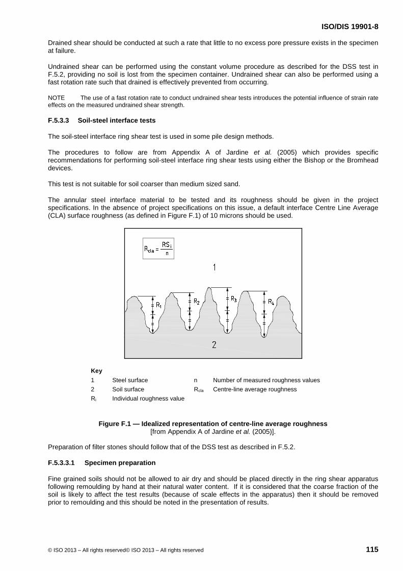
ISO/DIS 19901-8
© ISO 2013 – All rights reserved© ISO 2013 – All rights reserved 115
Drained shear should be conducted at such a rate that little to no excess pore pressure exists in the specimen at failure.
Undrained shear can be performed using the constant volume procedure as described for the DSS test in F.5.2, providing no soil is lost from the specimen container. Undrained shear can also be performed using a fast rotation rate such that drained is effectively prevented from occurring.
NOTE The use of a fast rotation rate to conduct undrained shear tests introduces the potential influence of strain rate effects on the measured undrained shear strength.
F.5.3.3 Soil-steel interface tests
The soil-steel interface ring shear test is used in some pile design methods.
The procedures to follow are from Appendix A of Jardine et al. (2005) which provides specific recommendations for performing soil-steel interface ring shear tests using either the Bishop or the Bromhead devices.
This test is not suitable for soil coarser than medium sized sand.
The annular steel interface material to be tested and its roughness should be given in the project specifications. In the absence of project specifications on this issue, a default interface Centre Line Average (CLA) surface roughness (as defined in Figure F.1) of 10 microns should be used.
Key 1 Steel surface n Number of measured roughness values 2 Soil surface Rcla Centre-line average roughness Ri Individual roughness value
Figure F.1 — Idealized representation of centre-line average roughness [from Appendix A of Jardine et al. (2005)].
Preparation of filter stones should follow that of the DSS test as described in F.5.2.
F.5.3.3.1 Specimen preparation
Fine grained soils should not be allowed to air dry and should be placed directly in the ring shear apparatus following remoulding by hand at their natural water content. If it is considered that the coarse fraction of the soil is likely to affect the test results (because of scale effects in the apparatus) then it should be removed prior to remoulding and this should be noted in the presentation of results.
ISO/DIS 19901-8
116 © ISO 2013 – All rights reserved© ISO 2013 – All rights reserved
If a fine grained soil is too hard to be remoulded into the equipment by hand, then the specimen should be mixed with distilled water (in the absence of the soil's natural pore water) to a water content corresponding to a Liquidity Index of between 0.0 and 0.2. Conversely, if the soil may be susceptible to large deformation during consolidation, then the specimen should be allowed to dry in air to a water content corresponding to a Liquidity Index of between 0.0 and 0.2.
Fine to medium sized sand specimens may be poured into place.
The soil should be placed in the apparatus in at least two layers, each layer being compacted by a uniform distribution of thumb pressures. Particular care is required to minimize the possibility of entrapping air within fine grained soil. Attention should be given to avoiding any irregularities in the soil at the boundary with the interface.
F.5.3.3.2 Consolidation
The total vertical (normal) stress to be used should be given in the project specifications. This stress should be applied following the procedures for incremental loading given in F.3
NOTE For both the Bromhead and Bishop devices, a minimum vertical stress of 50 kPa should be used to reduce errors associated with side wall friction. Furthermore, for the Bromhead device, the vertical consolidation strain should not be allowed to exceed 15 %.
F.5.3.3.3 Shear
Shearing consists of two stages. In the first stage, the specimen should be subjected to a series of fast shearing pulses for a total displacement of at least 1 metre. The shearing pulses should impose displacements of approximately 200 mm at a rate of 500 mm/min and should be separated by pause periods (at zero applied shear stress) of approximately 3 minutes in the Bromhead apparatus and approximately 10 minutes in the Bishop apparatus.
NOTE If significant squeezing/loss of soil between the confining ring and interface is observed during the first shearing stage (as indicated by significant change in specimen height), then (i) the rate of fast shearing should be slowed down and/or (ii) the proposed displacement at the fast rate should be reduced or (iii) the gap between the ring and the interface in Bishop's apparatus should be closed. This should be noted in the presentation of test results.
At the end of the first stage of shearing, excess pore pressures induced in the specimen should be allowed to fully dissipate. The specimen should then be reconsolidated prior to the second stage of shearing. The vertical stress to be used should be given in the project specifications and should be applied following the procedures for incremental loading given in F.3.
The second stage of shearing should be at a slow drained rate of displacement until ultimate residual conditions are established; this usually requires a displacement in excess of 10 mm. Rates of displacement required to ensure fully drained conditions in plastic clays are typically 0.02 mm/min and 0.005 mm/min in the Bromhead and Bishop devices respectively.
F.5.3.4 Presentation of test results
The following variables should be recorded during a ring-shear test:
time;
torque;
degree of rotation;
vertical force (for constant-volume shear);
vertical displacement.

ISO/DIS 19901-8
© ISO 2013 – All rights reserved© ISO 2013 – All rights reserved 117
The results from the ring shear test should be presented as plots of
the compression curve from the consolidation phase of the test;
average shear stress [see Bishop et al. (1971) on how to compute] versus degree of rotation or cumulative equivalent linear displacement;
vertical stress versus degree of rotation cumulative equivalent linear displacement for undrained (constant-volume) tests;
vertical displacement versus degree of rotation or cumulative equivalent linear displacement.
The following data should be included with the tabulated results:
effective vertical consolidation stress (maximum value and minimum values if specimen is preloaded or SHANSEP test is performed);
vertical consolidation strain (maximum value and minimum value if specimen is preloaded or SHANSEP test is performed).
F.5.4 Direct shear (DS) box test
The direct shear box test should be performed in accordance with ISO/TS 17892-10 or ASTM D3080.
Preparation of filter stones and consolidation procedures should follow those of the DSS test as described in F.5.2.
Drained shear should be conducted at such a rate that little to no excess pore pressure exists in the specimen at failure.
The following variables should be recorded during a direct shear box test:
time;
horizontal force;
horizontal displacement;
vertical displacement.
The results from the direct shear test should be presented as plots of
the compression curve from the consolidation phase of the test;
horizontal shear stress versus horizontal displacement;
vertical displacement versus horizontal displacement.
The following data should be included with the tabulated results:
effective vertical consolidation stress (maximum and minimum values if specimen is preloaded or SHANSEP test is performed);
vertical consolidation strain (maximum and minimum values if specimen is preloaded or SHANSEP test is performed).

ISO/DIS 19901-8
118 © ISO 2013 – All rights reserved© ISO 2013 – All rights reserved
F.6 Resonant column test
F.6.1 General
The resonant column test, which is used for determination of shear modulus and damping of soils at small strains, should be performed in accordance with ASTM D4015.
The following items should be given in the project specifications:
1) definition of resonance (peak output response or 90˚ input/output phase shift);
2) method for determining damping ratio;
3) duration of the consolidation increments (based either on time or on a creep criterion) and whether they are absolute or minimum requirements.
The preparation of soil samples should be in accordance with the requirements specified for triaxial tests (see F.4; except that side filter drains should not be used). Anisotropic consolidation should be used as described in F.4 for triaxial testing.
NOTE The use of anisotropic stresses results generally in a different Gmax value than an isotropic test which is consolidated to either the same vertical stress or octahedral stress.
F.6.2 Test procedure
F.6.2.1 General
For each resonant column test reading, the following parameters should be noted:
date;
time;
excitation (torque) amplitude and frequency;
resulting acceleration (strain) amplitude;
consolidation stresses;
specimen height;
volume change.
F.6.2.2 Initial shear modulus (Gmax) and material damping ratio (ξ) as functions of time
For each consolidation increment, resonant column test readings should be taken in a sequence similar to that of a consolidation test (e.g. at 1 min, 2 min, 4 min, 8 min, 15 min, 30 min, 60 min, 120 min, etc.) and well into secondary compression. The duration of a consolidation increment is typically at least one day. These periodic readings should be taken at a constant shear strain level. This common shear strain level should be at or below 10-3 %.
F.6.2.3 Shear modulus (G) and material damping ratio (ξ) as functions of shear strain
At the end of each consolidation phase (at significant time), a series of resonant column test readings at increasing levels of shear strain, starting at the lowest possible level, should be taken. Each subsequent larger shear strain measurement should immediately be followed by a measurement at the lowest possible shear strain.

ISO/DIS 19901-8
© ISO 2013 – All rights reserved© ISO 2013 – All rights reserved 119
For any intermediate consolidation increment, the maximum shear strain used should not exceed 10-2 % (a threshold shear strain). For the final consolidation step, after which the test is completed, the final measurements can be taken to the maximum shear strain attainable with the equipment being used and for the specimen being tested.
For a test series on samples in an over-consolidated state, the duration of the last confining stress level before unloading should be specified, and strictly maintained for all tests. This duration should be similar to that used in any parallel triaxial test programme.
F.6.3 Presentation of test results
The following plots of results should be presented for each consolidation increment:
effective axial and radial consolidation stresses, axial strain and volumetric strain;
initial shear modulus (Gmax) versus log time;
material damping ratio (ξ)versus log time;
shear modulus (G) versus log shear strain;
material damping ratio (ξ)versus log shear strain.
The time plots should indicate the time at which the strain measurements were taken. Other plots, such as normalized shear modulus (G/Gmax) versus shear strain (where Gmax is the small strain measurement following each larger strain G measurement) can also be presented.
Presentation of results should include
drainage conditions during each measurement (usually open drainage, since excess pore pressures are not generated at small shear strains);
definition of resonance;
method used for damping ratio determination;
definition of zero time for a particular consolidation increment (e.g. whether it is at the start of the initial confining stress or at the last deviator stress application).
The equivalent specimen radius used to define shear strain should also be included with the tabulated results.
F.7 Piezoceramic bender element tests
Piezoceramic bender elements are used to measure the shear wave velocity (vs), which can be used to compute the small strain shear modulus, Gmax, of a soil specimen.
The piezoceramic bender element technique can be used at any stage of a triaxial, DSS or consolidation test without interfering with the particular test. The test method is described in Dyvik and Madshus (1985), Dyvik and Olsen (1989) Leong et al. (2005) and Santamarina et al. (2001).
The preparation of the test specimen should be in accordance with the requirements specified for oedometer, triaxial and DSS tests.
Care should be taken when inserting the piezoceramic bender element into the top and bottom of the specimen in order to obtain good soil contact and not damage the bender element. The protrusion of the piezoceramic element from the base pedestal, as well as the height of the specimen, should be determined accurately.
ISO/DIS 19901-8
120 © ISO 2013 – All rights reserved© ISO 2013 – All rights reserved
Test equipment generally consists of a pair of piezoceramic bender elements mounted in the top cap and bottom pedestal of an oedometer, triaxial or DSS apparatus, a function generator, and an oscilloscope. Signal filters and signal amplifiers are also often used to enhance the quality of the received signals.
Once the specimen is mounted, the shear wave velocity can be measured at any time during the consolidation and testing phases of the test. The two bender elements act as a generator and a receiver of the shear waves respectively. The test consists of measuring the travel time of shear waves propagating from one end of the specimen to the other.
As described in Dyvik and Madshus (1985) and Dyvik and Olsen (1989) a stronger signal is obtained if the transmitting bender element is wired in a parallel electrical configuration, while the receiving bender element is wired in a series electrical configuration. The system delay time should be calibrated by placing the bender element pairs in direct tip-to-tip contact and measuring the system calibration time (tc). It also helps in interpretation of the signals if the bender element pairs are positioned so that they are positively polarized (i.e. an initial positive electrical signal in the transmitting element generates an initial positive electrical signal in the receiving element). A variety of signals are used for generating the transmitting signal, with the sine wave and square wave being the more common.
Varying the excitation frequency of the transmitting signal can produce different interpreted shear wave velocities [e.g. see ISSMGE TC 29 (2005) and Yamashita et al. (2009)]. An oscilloscope capable of measuring the short travel time of shear waves (especially for the short DSS and oedometer test specimens) should be used. The oscilloscope should be able to store the signals, either directly on the oscilloscope or on a linked PC for processing and printing out.
The shear wave velocity (vs) is calculated using the corrected travel time (∆t), which is equal to the measured travel time (t) minus the system delay time. There are several different methods for interpreting the arrival time, e.g. first arrival, peak-to-peak, cross-correlation, or first zero crossover. ISSMGE TC 29 (2005) and Yamashita et al. (2009) provide examples of these different interpretation methods.
NOTE Varying the method of interpretation used to determine the arrival time can produce different interpreted shear wave velocities [e.g. see ISSMGE TC 29(2005) and Yamashita et al. (2009)].
The shear wave velocity, usually reported in units of metres per second, is computed as:
vs = ltt/ ∆t
where ltt is the shear wave travel distance and is measured as the tip-to-tip distance between the bender elements
Gmax, usually reported in units of megapascals, is computed as:
Gmax = ρ vs2
where ρ is the total density of the specimen soil.
Normally the shear wave velocity is measured in the vertical direction (v) of a test specimen using a horizontally (h) polarized shear wave, and is thus often termed vvh. It is possible to measure the shear wave velocity in the horizontal direction of a test specimen, as for example described in Pennington et al. (2001) for triaxial specimens.
The type of transmitting signal and method of interpreting shear wave arrival should be documented and presented (when required).
The test results should be presented as shear wave velocity, vs, and calculated maximum (small strain) shear modulus, Gmax.
ISO/DIS 19901-8
© ISO 2013 – All rights reserved© ISO 2013 – All rights reserved 121
F.8 Thixotropy test
The thixotropy test provides data on the potential increase in undrained shear strength with time of a remoulded specimen, excluding the effect of consolidation. The measurement of undrained shear strength is typically conducted using the fall cone apparatus or the laboratory vane apparatus.
The soil specimen should be thoroughly remoulded at constant water content (typically the in situ water content). The remoulded soil should be placed in jars (glass or Plexiglas), taking care to minimize entrapment of air. The specimen should be covered with a cap and/or plastic foil and stored in a room with controlled temperature and humidity. Enough samples need to be prepared to perform the required number of measurements.
An initial measurement of intact and remoulded undrained shear strength, using the fall cone or laboratory vane, should first be conducted, followed by subsequent measurements of undrained shear strength with increasing time. The water content should also be measured at each time interval. Measurements should be performed on a clean-cut surface of the specimen to exclude any effects from a crust developing with time.
The tests should be conducted at suitable time intervals, such that the potential increase in undrained shear strength with time can be properly observed. In general, more frequent tests should be conducted at short time intervals, and that interval can be increased thereafter. An example set of time intervals is 0 h (initial reading), 1 h, 2 h, 4 h, 8 h, 1 day, 2 days, 4 days, 8 days, 15 days, 30 days and 60 days. The initial (t = 0) reading is particularly important, and a minimum of two such measurements should be conducted to check for repeatability.
The type of fall cone/laboratory vane and the factors used to convert the fall cone/laboratory vane measurements to undrained shear strength should be reported (see F.2.13.2 on fall cones).
The presentation of results from a thixotropy test should at least include plots of
undrained shear strength versus time;
remoulded shear strength versus time, i.e., the value measured after full remoulding of each specimen after the undrained shear strength measurement is completed;
measured water content versus time.
The graphical plot of test results should contain the following information:
project identification and location;
specimen identification and depth;
test type for measurement of shear strength (i.e. fall cone or laboratory vane);
initial water content.
F.9 Permeability
Relevant ISO and ASTM standards for determination of the coefficient of permeability (hydraulic conductivity) include:
ISO 17312 , Soil quality — Determination of hydraulic conductivity of saturated porous materials using a rigid-wall permeameter;
ISO 17313, Soil quality — Determination of hydraulic conductivity of saturated porous materials using a flexible-wall permeameter;
ASTM D2434, Standard Test Method for Permeability of Granular Soils (Constant Head);

ISO/DIS 19901-8
122 © ISO 2013 – All rights reserved© ISO 2013 – All rights reserved
ASTM D5084, Standard Test Methods for Measurement of Hydraulic Conductivity of Saturated Porous Materials Using a Flexible Wall Permeameter;
ASTM D5856, Standard Test Method for Measurement of Hydraulic Conductivity of Porous Materials Using a Rigid-Wall, Compaction-Mold Permeameter.
NOTE With appropriate equipment, rigid-wall permeability testing can be performed during conduct of a consolidation test (see F.3).
The permeant to be used for permeability testing should be given in the project specifications.
A constant head (and hence constant effective stress) procedure is preferred. During a permeability test, the pore pressure should be increased to achieve the required flow conditions. The test should continue until the termination criterion of the specific standard being used is achieved (which is typically steady-state conditions).
F.10 Heat conductivity test
A laboratory method using the thermal needle probe can provide the thermal conductivity of an undisturbed or remoulded soil sample, as described in ASTM D5334.
A long small-diameter needle, comprising both heating and temperature-measuring elements, is inserted into the specimen. On applying a constant current to the heater, the rise in temperature is recorded as a function of time and the thermal conductivity is obtained from an analysis of the temperature-time curve.
The needle is inserted into the undisturbed soil specimen while it is still in the sample tube or into the extruded specimen when is inserted into a slip ring.
Remoulded soil should be compacted into a metal or a plastic tube to the desired density before the needle is inserted.
The needle should be calibrated before use (in accordance with ASTM D5334), and the specimen should be in equilibrium with the room temperature. When the needle has been inserted, a known and constant current is applied and readings are taken at specified time intervals for a minimum of 100 s.
The thermal conductivity, λ, is computed from the linear portion of the plot of temperature versus the natural log (ln) of time.
The presentation of results from a thermal conductivity test should include at least a plot of measured temperature versus versus the natural log (ln) of time.
The plot of test results should contain the following information:
project identification and location;
sample identification and depth;
test type;
initial water content;
the computed thermal conductivity, λ [expressed in W/(m·K)];
the computed thermal resistivity, ρ = 1/λ [expressed in (m·K)/W)].

ISO/DIS 19901-8
© ISO 2013 – All rights reserved© ISO 2013 – All rights reserved 123
F.11 Other laboratory tests
Depending on project-specific requirements, other appropriate laboratory tests may be needed in addition to the common tests specified in this part of ISO 19901. The need for such tests should be given in the project specifications.
Examples of such tests include:
plane strain test;
true triaxial tests;
high pressure tests (e.g. consolidation tests or triaxial tests);
high or low temperature tests (e.g. consolidation tests or triaxial tests);
constant normal stiffness tests (DSS or ring shear);
torsional shear hollow cylinder;
piezoceramic bender element test with different orientations (e.g. vertical and horizontal in a triaxial test);
creep tests (DSS, triaxial);
specially adapted triaxial tests for measurement of capillary pressure in gas-charged sediments [e.g. Sultan et al. (2007)].
These tests should be described in detail, including information on the
purpose of the test;
apparatus/test equipment, with dimensions, capacities and accuracies;
required specimen dimensions/mass;
data acquisition system;
specimen preparation and mounting/dismounting;
test phase;
presentation of results;
previous experience and example test results (if any).
F.12 Geological and geochemical tests
F.12.1 General
The examination and analysis of soil samples can give useful information about the geological origin and history of the sediments, and should be performed by an experienced geologist.
The following information should be documented and reported
name of laboratory which will perform the tests;
standards and test procedures used.

ISO/DIS 19901-8
124 © ISO 2013 – All rights reserved© ISO 2013 – All rights reserved
The following subclauses contain specifications and requirements regarding geochemical tests and analyses. Depending on project-specific requirements, possible additional or substitute tests or analyses may be suggested.
F.2.10 to F.2.12 cover test procedures for organic content, carbonate content and soluble salts.
NOTE Additional guidance can be found in EN 1997-2 for some routine geochemical tests based on traditional testing methods which are within the capability of many geotechnical laboratories.
F.12.2 Visual description
A detailed visual description should be made on a fresh sample. The description should include the points listed in F.2.1.
The study of the structure of clay samples should be made on samples which are split halfway by a knife and the remaining half broken. On such surfaces both the sedimentary structure and macroscopic discontinuities (fissures) are best visible.
Minor soil components should be collected for a more detailed classification. If required, shell and shell fragments should be described, if possible by name, including the conditions under which they were living. The description of gravels and cobbles should include dimensions (in millimetres), classification of mineral or rock type, and angularity.
F.12.3 Mineralogical analysis
Mineralogical analysis may include
thin-section analysis of undisturbed soil samples, with scanning electron microscope studies;
quantification of minerals from X-ray diffraction.
A description of the structural formation (fabric) of the soil should be made, and the results from the analysis should include a photograph.
Since the methods of quantification of minerals from X-ray diffraction can differ among different laboratories, the following information should be provided:
sample preparation procedure;
original records from the X-ray diffractometer;
instrument type and instrument parameters used.
NOTE In Thomas et al. (2007) it is emphasized that X-ray diffraction allows clear qualitative identification of clay species, but does not provide information about mixed layers species, such as illite-smectite phases, which are common in clays of detritic origin. Therefore, exact quantitative determination of minerals in a mixture remains highly uncertain when using only the X-ray diffraction method.
F.12.4 Amino acid chronology
Amino acid chronology should be performed by a specialized laboratory. The method of analysis should be described, and previous experience should be documented.
F.12.5 Stable oxygen isotope analysis
Stable isotope analysis should be performed by a specialized laboratory. The method of analysis should be described, and previous experience should be documented.

ISO/DIS 19901-8
© ISO 2013 – All rights reserved© ISO 2013 – All rights reserved 125
F.12.6 Gas in sediment samples
Samples for shallow gas analysis should be stored either in airtight tin cans or in plastic bags, and frozen immediately. If tins are used, the atmosphere in the tins should be filled with nitrogen. If plastic bags are used, excess atmosphere should be removed by squeezing the bags before closing. The ideal method of freezing is the use of either liquid nitrogen or dry ice (solid CO2). The samples should be stored and transported to the laboratory in a frozen state.
The following types of gas analysis may be performed:
headspace gas (can be measured only on samples stored in tins);
occluded gas (gas dissolved in the pore water);
adsorbed gas (gas adsorbed onto the clay minerals);
total gas (instead of differentiating between occluded and adsorbed gases);
gas isotope analysis (e.g. carbon isotope ratios of methane, ethane and propane), where the data can be used to identify the origin of the gas.
F.12.7 14C dating (age determination)
Dating of organic material or shells by the 14C dating method can be performed if a sufficient amount of good quality soil is available. For conventional dating, 5 g to 10 g of carbonate material is needed, whereas only a few milligrams is needed for 14C analysis in an accelerator mass spectrometer.
F.12.8 Nanofossil and microfossil analysis
If required, representative soil samples should be sent to a specialist laboratory, and the analysis should be performed by personnel with experience in nanofossil and microfossil analyses of sediments.
The preparation technique, analysis procedure, and results of raw data showing the percentages of different species should be reported.
F.12.9 Soil corrosiveness
The specific tests to be performed as part of a soil corrosiveness analyses should be given in the project specifications.
a) Offshore testing
Samples for the sulphate-reducing bacteria (SRB) test and analysis of acid-soluble sulphate should be placed in airtight cans under a nitrogen atmosphere and sealed with plastic foil immediately after sampling. The cans should be stored cold (< 4 °C) in order to prevent biological and chemical changes.
Resistivity measurements should be carried out on naturally wet samples in a soil box with parallel electrodes, using a high-frequency resistivity meter.
pH measurements should be carried out directly on wet samples using a combined electrode and ph-meter.
Description of the soil sample, especially with regard to colour and odour, should be documented.
The undisturbed part of soil samples for sulphate, total sulphur, inorganic and organic carbon analyses should be placed in an evacuated airtight plastic bag and stored cold (< 4 °C).
b) Onshore testing

ISO/DIS 19901-8
126 © ISO 2013 – All rights reserved© ISO 2013 – All rights reserved
Samples for the sulphate-reducing bacteria (SRB) test should be brought to the laboratory without delay.
Acid-soluble sulphate should be measured on the same sealed sample used for the SRB test, and in accordance with NS 4737.
For sulphate analysis, the reduced part of the bag sample or the rest of the SRBs should be squeezed carefully for less than one-fifth of its pore water through a fine paper filter. The pore water should be kept under nitrogen atmosphere and analysed, preferably using an ion chromatograph.
Total sulphur should be analysed on dry powder samples. Inorganic and organic carbon should be analysed on dry powder samples as previously described. For analysis to be conducted on a dry powder sample, 30 g to 40 g of the bag sample should be dried and crushed fine in a mortar.
F.13 Rock testing
This part of ISO 19901 does not cover details of laboratory testing of rock. Guidance for classification and laboratory testing of rock materials is provided in various standards, in particular ASTM standards on soil and rock and also (EN 1997-2, ISRM and BS 5930).
The following standards are available for laboratory testing of rock samples:
a) ISO 14689-1, Geotechnical investigation and testing — Identification and classification of rock — Part 1: Identification and description
b) EN 1997-2:2007, Eurocode 7 — Geotechnical design — Part 2: Ground investigation and testing (mainly based on ISRM suggested methods for rock characterization, testing and monitoring):
Clause 5, Laboratory tests on soil and rock;
Annex T, Preparation of specimen for testing of rock material;
Annex U, Classification testing of rock material (water content, density/porosity);
Annex V, Swelling testing of rock material;
Annex X, Strength testing of rock material (uniaxial, point load, direct shear, brazil and triaxial compression tests).
c) ASTM standards:
D2845, Laboratory determination of pulse velocities and ultrasonic elastic constants of rock;
D2936, Direct tensile strength of intact rock core specimens;
D2938, Standard test method for unconfined compressive strength of intact rock core specimens;
D3967, Splitting tensile strength of intact rock core specimens;
D4543, Preparing rock core specimens and determining dimensional and shape tolerances;
D4611, Specific heat of rock and soil;
D5079, Standard practices for preserving and transporting rock core samples;
D5607, Laboratory direct shear strength tests of rock specimens under constant normal force;
D5731, Point load strength index of rock and application to rock strength classifications;

ISO/DIS 19901-8
© ISO 2013 – All rights reserved© ISO 2013 – All rights reserved 127
D5878, Standard guides for using rock-mass classification systems for engineering purposes;
D6032, Determining rock quality designation (RQD) of rock core;
D7012, Compressive strength and elastic moduli of intact rock core specimens under varying states of stress and temperatures;
D7070, Creep of rock core under constant stress and temperature.

ISO/DIS 19901-8
128 © ISO 2013 – All rights reserved© ISO 2013 – All rights reserved
Annex G (informative)
Reporting
G.1 General
The extent of reporting and the reporting format are part of the scope of work that needs to be specified by the soil investigation client. If not otherwise specified by the client, the reporting should be organized in chronological order covering:
field operations and preliminary results;
measured and derived geotechnical parameters and final results;
data interpretation and evaluation of representative geotechnical parameters.
An example reporting format is presented in Table G.1, however alternative reporting formats can also be used including contractor’s usual practice.
The contents of each report should be presented in a logical and clear manner.
The actual scope of reporting, which may be limited to the field operations, or may include data interpretation and evaluation of representative geotechnical parameters, can be presented in a stand-alone report or in separate reports (in line with the project details specified by the soil investigation client).
Depending on the project-specific requirements and the type of soil investigation, more or less complex geotechnical issues may be addressed in the report, i.e.:
comprehensive soil investigation for detailed design of the foundations for a gravity-based structure, piled jacket platform or similar offshore structure of relatively large dimensions;
soil investigation of regional character in an early project phase, e.g. for a new development site for which the type and location or number of platforms are not fixed at the time of the investigation;
soil investigation with limited scope for surveying a site already covered by a previous investigation, or for a small facility such as a small subsea structure with shallow foundations;
soil investigation along a pipeline route, where a limited penetration and long distances are specific to the coverage requirements;
soil investigation for geohazards identification purposes.
Any active geological processes or geohazards that can affect the geotechnical parameters or the integrity of the foundations for the planned structure should be evaluated and reported. Such geohazards can consist of: seabed crust, past seafloor instability, presence of gas in the pore water or shallow soils (with special attention to any effect of pore pressures in excess of hydrostatic, and the effect of gas on the soil behaviour), shallow water-flow sands, mass transport deposits, hydrates, permafrost, etc. The extent of the geohazards assessment should be clearly specified and defined in the scope of work, since this may require different information than that obtained in a conventional marine soil investigation.
NOTE The process of geotechnical design consists of successive phases, the first of which covers the evaluation of the soil investigation data and results, the next one is devoted to the determination of representative geotechnical parameters, and the last phase covers the design calculations. General rules for the first two phases are given in this part
ISO/DIS 19901-8
© ISO 2013 – All rights reserved© ISO 2013 – All rights reserved 129
of ISO 19901, whereas guidance for the design of foundations for offshore structures can be found in the ISO 19901 series (see Foreword).
G.2, G.3 and G.4 give guidelines/recommendations for various reporting stages which may or may not be part of the scope of work, depending on the project-specific requirements defined by the client.
G.2 Field operations and preliminary results
Reporting of the field operations and preliminary results should comprise a description of the drilling, in situ testing and sampling techniques used, for example consisting of:
description of the soil investigation platform and procedure;
drilling equipment and procedures, with particular emphasis on the following topics:
log of drilling performance, to the extent needed for evaluating the soil conditions;
any change in mud composition or density (as appropriate);
possible influence of the drilling conditions on the quality of the in situ testing and sampling results in the various soils encountered;
verification checks documentation and/or calibration certificates of in situ testing and laboratory testing equipments;
information on positioning operations, equipment and procedures, with proper documentation of verification checks of positioning equipment;
log of daily field activities;
preliminary results of all offshore geotechnical measurements from in situ tests and offshore laboratory tests.
G.3 Measured and derived geotechnical parameters and final results
After verification of field data and completion of onshore laboratory tests, detailed factual reporting of the measured and derived geotechnical parameters and final results will usually supersede the previous reporting of preliminary field results.
In addition to documenting each individual test, geotechnical boring logs and soil profiles should be presented by compiling the main soil data and results in an overviewable format. Such geotechnical logs and soil profiles should typically comprise the following information, including measured and derived parameters plotted versus depth:
description of the soil in each geotechnical formation;
water content and plasticity parameters;
soil unit weight;
strength properties within the soil strata, consisting of:
undrained shear strength of clays, by correlation with in situ tests, and/or for various types of laboratory tests, with both intact and remoulded strengths;
relative density of sands, as derived from the in situ CPTU cone resistance, for example.
The following soil properties and geotechnical parameters are typically presented:
soil description;

ISO/DIS 19901-8
130 © ISO 2013 – All rights reserved© ISO 2013 – All rights reserved
depth below seafloor, or elevation with respect to a specified reference level (e.g. LAT or MSL);
appropriate soil classification data, i.e.:
water content;
plastic and liquid limits, plasticity index and liquidity index;
particle size distribution;
soil unit weight;
density of solid particles;
carbonate, organic and salt contents (where relevant);
in sand layers, maximum and minimum void ratios, in situ density and relative density measured from laboratory test or estimated from correlations with in situ tests;
in clay layers, index undrained shear strength from pocket penetrometer, fall cone, torvane or laboratory/motor vane tests (as applicable);
seafloor and in situ temperature (where applicable);
effective overburden stress, po' or σvo';
in situ pore water pressure, uo, including any excess pore pressure (if relevant);
preconsolidation stress, pc' , overconsolidation ratio, OCR, and yield stress ratio, YSR;
coefficient of consolidation, cv and compression index, Cc (if relevant);
for sand layers, drained friction angle in compression or extension, from various types of laboratory tests (e.g. triaxial tests, plane strain tests, or shear box tests, as applicable);
for clay layers, undrained shear strength from various types of laboratory tests (e.g. unconsolidated UU triaxial tests, isotropically or anisotropically consolidated CIU or CAU triaxial tests, and/or DSS tests, as applicable), or from correlations with in situ tests, with estimate of clay anisotropy, and remoulded shear strength with sensitivity, St.
Special consideration should be given to anomalous results for a given strata when compared with results from other types of laboratory or in situ tests capable of measuring the same geotechnical parameter. Such anomalous results should be clearly identified, and a thorough evaluation be performed for assessing whether these results are representative of the in situ soil conditions or not.
G.4 Data interpretation and evaluation of representative geotechnical parameters
Interpretation of all soil investigation data and results should be reported, including methods and procedures used for evaluation of the representative geotechnical parameters.
Stratigraphic schematization and subdivision into geotechnical formations should consider the following aspects:
strata in which geotechnical parameters vary only slightly and occasionally may be considered as one formation;

ISO/DIS 19901-8
© ISO 2013 – All rights reserved© ISO 2013 – All rights reserved 131
a sequence of thinly bedded strata with differing geotechnical composition and/or mechanical properties may be considered as one formation only if the overall behaviour is relevant for the design case under consideration and if the behaviour can be adequately represented by the geotechnical parameters selected for the formation;
when deriving the boundary between different formations, one may apply linear interpolation between the investigation points, provided the spacing is sufficiently small and the local geological conditions are sufficiently uniform (to be justified and documented).
Stratigraphic schematization interpreted for the geotechnical boring logs may be compared for consistency with available geophysical survey data. The observations or measurements during drilling may also be used as an indicator in determining boundaries between different strata.
Depending on the planned type of structure and the foundation design load case under consideration, different requirements may apply for the evaluation of the geotechnical parameters, for example:
detailed characterization of the top 1 m of sediment, of particular concern for pipelines and risers;
evaluation of soil properties with depth for the design of driven piles, with particular emphasis near the pile toe level for end-bearing capacity in a layered soil profile;
evaluation of cyclic soil properties and relative permeability of strata for facilities under various periods and rates of loading, such as undrained bearing capacity and shear stresses in the soil caused by cyclic loading of a gravity-based structure, mobilization of passive suction for skirted foundations or suction piles, effect of earthquake loading, etc.;
in unconventional soils (such as carbonate soils, mica, glauconite, permafrost, boulder clay, or other unconventional soils), special care should be taken when deriving geotechnical parameters from the test data.
A number of geotechnical parameters are independent of the type of structure, foundation or load case under consideration. On the other hand, different values of the same geotechnical parameter (e.g. undrained shear strength of clay, friction angle of sand, etc.) can depend on the load case or the geotechnical issue to be addressed (such as bearing capacity, calculation of settlement, displacement, or prediction of installation behaviour, etc.). Therefore, the list of geotechnical parameters to be provided in the report will vary from case to case and should be defined in the project specifications.
Averaging of mechanical properties over a sequence of strata for foundations mobilizing a large volume of soil may be possible, but should be used with caution since averaging can mask the presence of a weaker zone. Situations where it is important that weak zones are identified can include:
horizontal sliding modes for the shallow foundation of a gravity-based structure;
assessment of punch-through risk for a jack-up spudcan;
axial bearing capacity of piles where end bearing has a significant contribution;
areas where slope stability is a concern.
Recommendations regarding any necessary further in situ or laboratory tests may be included in the report, with comments justifying the need for this additional work.

ISO/DIS 19901-8
132 © ISO 2013 – All rights reserved© ISO 2013 – All rights reserved
Table G.1 — Example reporting format and contents
(Alternative reporting formats can also be used including contractor’s usual practice.)
Field Operations and
Preliminary Results
Measured and Derived Geotechnical Parameters
and Final Results
Data Interpretation and Evaluation of Representative
Geotechnical Parameters
Executive summary Executive summary Executive summary
Investigated points, with maps and coordinates
Investigated points, with maps and coordinates
Investigated points, with maps and coordinates
List of symbols and terms used List of symbols and terms used List of symbols and terms used
Scope of field operations, with description of the soil investigation platform and procedure
Scope of field operations, with description of the soil investigation platform and procedure
Summary of soil conditions and stratigraphic schematization
Log of drilling operations (when used for soil data evaluation)
Final geotechnical boring logs and soil profiles, with proposed stratigraphic schematization
Intended structure(s) and design case(s) under consideration
In situ testing operations, procedures and preliminary results
In situ testing procedures and final results
Evaluation of data and results, with interpretation methods and procedures
Sampling operations, procedures and preliminary results
Sampling procedures and final results Recommended representative geotechnical parameters
Field laboratory test results Laboratory testing procedures and final results
Geological features, faults and other geohazards of geotechnical concern
Preliminary geotechnical boring logs Other test results (e.g. multi-sensor core logging or X-ray logging, chemical tests, geological tests, etc.)
Recommendations on additional soil data possibly needed
Inventory of recovered samples and proposed onshore laboratory test programme
Other data and results
(e.g. geophysical data, results of previous soil investigation, etc.)
References
Log of daily field activities References
List of parties involved in soil investigation
Water depth and tidal measurements
Documentation of verification checks, equipment calibration, and metrological confirmation
References

ISO/DIS 19901-8
© ISO 2013 – All rights reserved© ISO 2013 – All rights reserved 133
Bibliography
Standards and Codes
[1] ISO 9000 series, Quality Management Systems
[2] ISO 10693, Soil quality — Determination of carbonate content — Volumetric method
[3] ISO 10694, Soil quality — Determination of organic and total carbon after dry combustion (elementary analysis)
[4] ISO/TR 14685, Hydrometric determinations — Geophysical logging of boreholes for hydrogeological purposes — Considerations and guidelines for making measurements
[5] ISO 14688-1, Geotechnical investigation and testing — Identification and classification of soil — Part 1: Identification and description
[6] ISO 14688-2, Geotechnical investigation and testing — Identification and classification of soil — Part 2: Principles for a classification
[7] ISO 14689-1, Geotechnical investigation and testing — Identification and classification of rock — Part 1: Identification and description
[8] ISO 17312, Soil quality — Determination of hydraulic conductivity of saturated porous materials using a rigid-wall permeameter
[9] ISO 17313, Soil quality — Determination of hydraulic conductivity of saturated porous materials using a flexible-wall permeameter
[10] ISO/TS 17892-1, Geotechnical investigation and testing — Laboratory testing of soil — Part 1: Determination of water content
[11] ISO/TS 17892-2, Geotechnical investigation and testing — Laboratory testing of soil — Part 2: Determination of density of fine-grained soil
[12] ISO/TS 17892-3, Geotechnical investigation and testing — Laboratory testing of soil — Part 3: Determination of particle density — Pycnometer method
[13] ISO/TS 17892-4, Geotechnical investigation and testing — Laboratory testing of soil — Part 4: Determination of particle size distribution
[14] ISO/TS 17892-5, Geotechnical investigation and testing — Laboratory testing of soil — Part 5: Incremental loading oedometer test
[15] ISO/TS 17892-6, Geotechnical investigation and testing — Laboratory testing of soil — Part 6: Fall cone test
[16] ISO/TS 17892-7, Geotechnical investigation and testing — Laboratory testing of soil — Part 7: Unconfined compression test on fine-grained soils
[17] ISO/TS 17892-8, Geotechnical investigation and testing — Laboratory testing of soil — Part 8: Unconsolidated undrained triaxial test
[18] ISO/TS 17892-9, Geotechnical investigation and testing — Laboratory testing of soil — Part 9: Consolidated triaxial compression tests on water-saturated soils

ISO/DIS 19901-8
134 © ISO 2013 – All rights reserved© ISO 2013 – All rights reserved
[19] ISO/TS 17892-10, Geotechnical investigation and testing — Laboratory testing of soil — Part 10: Direct shear tests
[20] ISO/TS 17892-11, Geotechnical investigation and testing — Laboratory testing of soil — Part 11: Determination of permeability by constant and falling head
[21] ISO/TS 17892-12, Geotechnical investigation and testing — Laboratory testing of soil — Part 12: Determination of Atterberg limits
[22] ISO 19901-4, Petroleum and natural gas industries — Specific requirements for offshore structures — Part 4: Geotechnical and foundation design considerations
[23] ISO 19901-6, Petroleum and natural gas industries – Specific requirements for offshore structures – Part 6: Marine operations
[24] ISO 22475-1, Geotechnical investigation and testing — Sampling methods and groundwater measurements — Part 1: Technical principles for execution
[25] ISO/TS 22475-2, Geotechnical investigation and testing — Sampling methods and groundwater measurements — Part 2: Qualification criteria for enterprises and personnel
[26] ISO/TS 22475-3, Geotechnical investigation and testing — Sampling methods and groundwater measurements — Part 3: Conformity assessment of enterprises and personnel by third party
[27] ISO/DIS 22476-9, Geotechnical investigation and testing — Field testing — Part 9: Field vane test
[28] ISO 31000, Risk management — Principles and guidelines
[29] ASTM International (2007), ASTM Standards on Disc, Vol. 04.08: Soil and Rock (I): D420 to D5611, Vol. 04.09: Soil and Rock (II): D5714 to Latest
[30] ASTM D422, Standard Test Method for Particle-Size Analysis of Soils
[31] ASTM D854, Standard Test Methods for Specific Gravity of Soil Solids by Water Pycnometer
[32] ASTM D2166, Standard Test Method for Unconfined Compressive Strength of Cohesive Soil
[33] ASTM D2216, Standard Test Methods for Laboratory Determination of Water (Moisture) Content of Soil and Rock by Mass
[34] ASTM D2434, Standard Test Method For Permeability Of Granular Soils (Constant Head)
[35] ASTM D2435, Standard Test Methods for One-Dimensional Consolidation Properties of Soils Using Incremental Loading
[36] ASTM D2487, Standard Classification of Soils for Engineering Purposes (Unified Soil Classification System)
[37] ASTM D2488, Standard Practice for Description and Identification of Soils (Visual-Manual Procedure)
[38] ASTM D2573, Standard Test Method for Field Vane Shear Test in Cohesive Soil
[39] ASTM D2845, Standard Test Method for Laboratory Determination of Pulse Velocities and Ultrasonic Elastic Constants of Rock
[40] ASTM D2850, Standard Test Method for Unconsolidated-Undrained Triaxial Compression Test on Cohesive Soils
[41] ASTM D2936, Standard Test Method for Direct Tensile Strength of Intact Rock Core Specimens

ISO/DIS 19901-8
© ISO 2013 – All rights reserved© ISO 2013 – All rights reserved 135
[42] ASTM D2974, Standard Test Methods for Moisture, Ash, and Organic Matter of Peat and Other Organic Soils
[43] ASTM D3080, Standard Test Method for Direct Shear Test of Soils Under Consolidated Drained Conditions
[44] ASTM D3740, Standard Practice for Minimum Requirements for Agencies Engaged in Testing and/or Inspection of Soil and Rock as Used in Engineering Design and Construction
[45] ASTM D3967, Standard Test Method for Splitting Tensile Strength of Intact Rock Core Specimens
[46] ASTM D3999, Standard Test Methods for the Determination of the Modulus and Damping Properties of Soils Using the Cyclic Triaxial Apparatus
[47] ASTM D4015, Standard Test Methods for Modulus and Damping of Soils by Resonant-Column Method
[48] ASTM D4083, Standard Practice for Description of Frozen Soils (Visual Manual Procedure)
[49] ASTM D4186, Standard Test Method for One-Dimensional Consolidation Properties of Saturated Cohesive Soils Using Controlled-Strain Loading
[50] ASTM D4253, Standard Test Methods for Maximum Index Density and Unit Weight of Soils Using a Vibratory Table
[51] ASTM D4254, Standard Test Methods For Minimum Index Density And Unit Weight Of Soils And Calculation Of Relative Density
[52] ASTM D4318, Standard Test Methods for Liquid Limit, Plastic Limit, and Plasticity Index of Soils
[53] ASTM D4373, Standard Test Method for Rapid Determination of Carbonate Content of Soils
[54] ASTM D4452, Standard Practice for X-Ray Radiography of Soil Samples
[55] ASTM D4542, Standard Test Method for Pore Water Extraction and Determination of the Soluble Salt Content of Soils by Refractometer
[56] ASTM D4543, Standard Practices for Preparing Rock Core as Cylindrical Test Specimens and Verifying Conformance to Dimensional and Shape Tolerances
[57] ASTM D4611, Standard Test Method for Specific Heat of Rock and Soil
[58] ASTM D4648, Standard Test Method for Laboratory Miniature Vane Shear Test for Saturated Fine-Grained Clayey Soil
[59] ASTM D4767, Standard Test Method for Consolidated Undrained Triaxial Compression Test for Cohesive Soils
[60] ASTM D5079, Standard Practices for Preserving and Transporting Rock Core Samples
[61] ASTM D5084, Standard Test Methods For Measurement Of Hydraulic Conductivity Of Saturated Porous Materials Using A Flexible Wall Permeameter
[62] ASTM D5334, Standard Test Method for Determination of Thermal Conductivity of Soil and Soft Rock by Thermal Needle Probe Procedure
[63] ASTM D5550, Standard Test Method for Specific Gravity of Soil Solids by Gas Pycnometer
[64] ASTM D5607, Standard Test Method for Performing Laboratory Direct Shear Strength Tests of Rock Specimens Under Constant Normal Force

ISO/DIS 19901-8
136 © ISO 2013 – All rights reserved© ISO 2013 – All rights reserved
[65] ASTM D5731, Standard Test Method for Determination of the Point Load Strength Index of Rock and Application to Rock Strength Classifications
[66] ASTM D5778, Standard Test Method for Electronic Friction Cone and Piezocone Penetration Testing of Soils
[67] ASTM D5856, Standard Test Method For Measurement Of Hydraulic Conductivity Of Porous Materials Using A Rigid-Wall, Compaction-Mold Permeameter
[68] ASTM D5878, Standard Guides for Using Rock-Mass Classification Systems for Engineering Purposes
[69] ASTM D5311, Standard Test Method for Load Controlled Cyclic Triaxial Strength of Soil
[70] ASTM D5720, Standard Practice for Static Calibration of Electronic Transducer-Based Pressure Measurement Systems for Geotechnical Purposes
[71] ASTM D6032, Standard Test Method for Determining Rock Quality Designation (RQD) of Rock Core
[72] ASTM D6027, Standard Practice for Calibrating Linear Displacement Transducers for Geotechnical Purposes
[73] ASTM D6467, Standard Test Method for Torsional Ring Shear Test to Determine Drained Residual Shear Strength of Cohesive Soils
[74] ASTM D6528, Standard Test Method for Consolidated Undrained Direct Simple Shear Testing of Cohesive Soils
[75] ASTM D6913, Particle-Size Distribution (Gradation) of Soils Using Sieve Analysis.
[76] ASTM D7012, Standard Test Method for Compressive Strength and Elastic Moduli of Intact Rock Core Specimens under Varying States of Stress and Temperatures
[77] ASTM D7070, Standard Test Methods for Creep of Rock Core Under Constant Stress and Temperature
[78] ASTM D7400, Standard Test Methods for Downhole Seismic Testing
[79] BS 1377-3:1990, Methods of test for soils for civil engineering purposes — Part 3: Chemical and electro-chemical tests
[80] BS 1377-7, Methods of test for soils for civil engineering purposes — Part 7: Shear strength tests (total stress)
[81] BS 5930:1999, Code of practice for site investigations
[82] DNV RP-C207, Recommended Practice for Statistical Representation of Soil Data, 2007
[83] EN 1997-1, Eurocode 7: Geotechnical design — Part 1: General rules
[84] EN 1997-2:2007, Eurocode 7: Geotechnical design — Part 2: Ground investigation and testing
[85] GOST 25100-95, Soils. Classification
[86] IEC 61892-7, Mobile and fixed offshore units — Electrical installations — Part 7: Hazardous areas
[87] International Hydrographic Organization, IHO Standards for Hydrographic Surveys, 5th edn., International Hydrographic Bureau, Monaco, Special Publication No. 44, 2008
[88] ISM Code, International Safety Management Code and Guidelines on Implementation of the ISM Code, 3rd edn, International Maritime Organization, 2010, 81 pp.

ISO/DIS 19901-8
© ISO 2013 – All rights reserved© ISO 2013 – All rights reserved 137
[89] ISPS, International Ship And Port Facility Security Code, International Maritime Organization, 2003
[90] ISRM, Suggested Methods for Rock Characterization, Testing and Monitoring — Part 1: Site Characterization, International Society for Rock Mechanics, 1981
[91] ISSMGE Technical Committee 1, Geotechnical and Geophysical Investigations for Offshore and Nearshore Developments, International Society for Soil Mechanics and Geotechnical Engineering, London, 2005
[92] MARPOL, International Convention for the Prevention of Pollution from Ships, International Maritime Organization, 1973
[93] NS 4737, Water Analysis — Determination Of Sulphide Content Of Waste Water — Colorimetric Method
[94] OGP-IMCA, Guidelines for GNSS Positioning in the Oil and Gas Industry, International Association of Oil & Gas Producers (OGP) and the International Marine Contractors Association (IMCA), 2010
[95] SOLAS, International Convention for the Safety of Life at Sea, International Maritime Organization, 1974
[96] SUT Offshore Site Investigation and Geotechnics Committee (2004), Guidance Notes on Geotechnical Investigations for Marine Pipelines: Issue: OSIG Rev 03, Society for Underwater Technology (SUT), London.
[97] SUT Offshore Site Investigation and Geotechnics Committee (2000), Guidance Notes on Geotechnical Investigations for Subsea Structures: Revision: 02, Society for Underwater Technology (SUT), London.
Published articles
[98] Baldi, G., Hight, D.W., Thomas, G.E., State-of-the-Art: A re-evaluation of conventional triaxial test methods, Advanced Triaxial Testing of Soil and Rock, ASTM STP 977, Donaghe et al. Eds., ASTM, Philadelphia, (1988), pp. 219-263.
[99] Becue, J.P., Puech, A. and Lhuillier, B., Recording of Drilling Parameters: A Complementary Tool for Improving Geotechnical Investigation in Carbonate Formations, Proc. Int. Conference on the Engineering of Calcareous Sediments, A. A. Balkema, ed., Perth, 1988
[100] Bishop, A.W., Green, G.E., Garga, V.K., Andresen, A. and Brown, J.D., A New Ring Shear Apparatus and its Application to the Measurement of Residual Strength. Geotechnique, 21 (1971), pp. 273-328
[101] Bjerrum,L. Problems of soil mechanics and construction on soft clays. Proc. 8th Int. Conf. on Soil Mechnics and Foundation Eng., Moscow, 1973, 3: 111-159.
[102] Black, D.K., and Lee, K.L., Saturating Laboratory Samples by Back Pressure. J. Soil Mechanics and Foundations Division, ASCE, 99, No.SM1, 1973, pp.75-93
[103] Bourillet, J.F., Damy, G., Dussud, L., Sultan, N. and Woerther, P., Behaviour of a Piston Corer from Accelerometers and New Insights on Quality of the Recovery, Proc. Society for Underwater Technology (SUT) Conference on Offshore Site Investigation and Geotechnics, Royal Geographical Society, London, 11-13 September, 2007
[104] Bromhead, E.N., A Simple Ring Shear Apparatus, Ground Engineering, 12 (1979), pp. 40-44
[105] Buckley D.E., MacKinnon W.G., Cranston R.E. and Christian H.A., Problems with piston core sampling: Mechanical and geochemical diagnosis. Marine Geol., 117 (1994), pp. 95-106
[106] Casagrande, A., Notes on Soil Mechanics – First Semester, Harvard University (unpublished), 1938
[107] Clayton, C.R.I., Stiffness at small strain: research and practice. Géotechnique, 61(1), (2011), pp. 5-38.

ISO/DIS 19901-8
138 © ISO 2013 – All rights reserved© ISO 2013 – All rights reserved
[108] Clarke, A.R. and Walker, B.F., A Proposed Scheme for the Classification and Nomenclature for Use in the Engineering Description of Middle Eastern Sedimentary Rocks, Geotechnique, 17(1) (1977), pp. 93-99
[109] Clayton, C.R.I. and Hight, D.W., Laboratory testing of natural soils – Some factors affecting performance, Characterisation and Engineering Properties of Natural Soils, Tan et al. Eds., Vol. 3 (2007), pp. 1535-1599.
[110] Digby, A., Wireline Logging for Deepwater Geohazard Assessment. Proc. SUT Int. Conference on Offshore Site Investigation and Geotechnics, London, UK, 26-28 November, 2002
[111] Dreimanis, A. Quantitative gasometric determination of calcite and dolomite by using Chittick apparatus. J. Sediment. Petrol. Vol. 32, (1962), pp. 520-529.
[112] Dyvik, R., Lacasse, S., and Martin, R. Coefficient of lateral stress from oedometer cell. Int. Conf. on Soil Mechanics and Foundation Engineering, San Francisco, Vol. 2, 1985, pp 1003-1006
[113] Dyvik, R. and Madshus, C., Lab Measurements of Gmax Using Bender Elements, Proc. ASCE Annual Convention on Advances in Art of Testing Soils under Cyclic Conditions, Detroit, October, 1985
[114] Dyvik, R. and Olsen, Gmax measured in oedomeder and direct simple shear tests using bender elements. NGI Publication No. 181. 1989
[115] Hight, D.W., A simple piezometer probe for the routine measurement of pore pressures in triaxial tests on saturated soils, Géotechnique, 32(4) (1982), pp. 396-402.
[116] Head, K.H., Manual of Soil Laboratory Testing, Vol. 3: Effective stress tests. Pentech Press, 1986
[117] ISSMGE TC 29. "International Parallel Test on the Measurement of Gmax Using Bender Elements Organized by TC-29" Report of Int. Society for Soil Mechanics and Geotechnical Engineering Technical Committee TC-29, 2005. Available at www.jiban.or.jp/file/e/tc29/BE_Inter_PP_Test_en.pdf
[118] Jardine, R., Chow, F., Overy, R. and Standing, J. ICP Design methods for driven piles in sands and clays. Thomas Telford Publishing, London, 2005.
[119] Jardine, R.J., Symes, M.J.P.R., and Burland, J.B., The measurement of soil stiffness in the triaxial apparatus. Géotechnique, 34(3), (1984), pp. 323-340.
[120] Janbu,N.,The resistance concept applied to the deformation of soils. Proc. 7th Int. Conf. on Soil Mechanics and Found. Eng., Mexico City. 1969, 1:191-196.
[121] Kaye,S., Goedemoed, S.S. & Vermeijden, C. A., Influence of salinity on soil properties. In Gouvenec S. And Cassidy, M. (eds) Proc. Int. Symp. on Frontiers in Offshore Geotechnics. Taylor and Francis, 1087 – 1093. et al., 2005
[122] Lacasse, S., Nadim, F., Rahim, A. and Guttormsen, T.R., Statistical Description of Characteristic Soil Properties, Proc. Offshore Technology Conference, OTC paper 19117, Houston, May, 2007
[123] Ladd,C.C. Stability evaluation during stage construction. J. of Geotechnical Eng., 1991, 117(4): 540-615.
[124] Ladd, C.C. and Foott, R., New Design Procedure for Stability of Soft Clays, ASCE J. Geotech. Eng. Div., 100, No. GT7 (1974), pp. 763-786
[125] Ladd, C.C. and DeGroot, D.J. Recommended practice for soft ground site characterization: Arthur Casagrande Lecture. Proc. 12th Panamerican Conf. on Soil Mechanics and Geotechnical Eng., 1: 3-57. 2003
[126] Lees, G., A New Method for Determining the Angularity of Particles, Sedimentology, 3(1), (1964)

ISO/DIS 19901-8
© ISO 2013 – All rights reserved© ISO 2013 – All rights reserved 139
[127] Leong, E.C., Yeo, S.H. and Rahardjo, H. Measuring Shear Wave Velocity using Bender Elements, ASCE Geotech. Testing J., 28(5), (2005), pp. 488-498
[128] Lunne, T., Berre, T., Andersen, K.H., Strandvik, S. and Sjursen, M. Effects of sample disturbance and consolidation procedures on measured shear strength of soft marine Norwegian clays, Canadian Geotech. J., 43 (2006), pp 726-750
[129] Lunne, T., Robertson, P.K. and Powell, J.J.M., Cone Penetration Testing in Geotechnical Practice, Blackie Academic & Professional eds., 1997
[130] Malek, A. Cyclic Behavior of Clay in Undrained Simple Shearing and Application to Offshore Tension Piles. Sc.D. Thesis, MIT, Cambridge, MA, 1987.
[131] Mesri, G., and Hayat, T.M. "The coefficient of earth pressure at rest." Can. Geotech. J., 30(4), (1993), 647-666.
[132] Mesri, G., Kwan Lo, D.O., and Feng, T.W. "Settlement of embankments on soft clays." Proc., Vertical and Horizontal Deformations of Foundations and Embankments. ASCE GSP 40, College Station, 1, 1994, pp. 8-56
[133] Nauroy, J.F., Dubois, J.C., Colliat, J.L., Kervadec, J.P. and Meunier, J., The GEOSIS Method for Integrating VHR Seismic and Geotechnical Data in Offshore Site Investigations, Proc. SUT Int. Conference on Offshore Site Investigation and Foundation Behaviour, London, November, 1998
[134] Noorany, I. Phase relations in marine soils. Journal of Geotechnical Engineering, vol 110:4, (1984), pp. 539-543
[135] Osborne, J.J., Teh, K.L., Houlsby, G.T., Cassidy, M.J., Bienen, B. and Leung, C.F., (2010), “Improved guidelines for the prediction of geotechnical performance of spudcan foundations during installation and removal of jack-up units, Joint Industry-funded Project”, InSafeJIP Revision 1b (errata) 18th Nov 2010.
[136] Pennington, D.S., Nash, D.F.T., and Lings, M.L., "Horizontally Mounted Bender Elements for Measuring Anisotropic Shear Moduli in Triaxial Clay Specimens," Geotechnical Testing Journal, GTJODJ, 24(2), (2001), pp. 133-144.
[137] Pettijohn, F.J., Sedimentary rocks, 2nd edn., Harper, New York, 1949.
[138] Peuchen, J., De Ruijter, M.R., Hospers, B. and Assen, R.L., Shear Wave Velocity Integrated in Offshore Geotechnical Practice, Proc. SUT Int. Conference on Offshore Site Investigation and Geotechnics, London, 26-28 November, 2002
[139] Peuchen, J.P. and Mayne, Rate Effects in Vane Shear Testing, Proc. SUT Int. Conference on Offshore Site Investigation and Geotechnics, London, 11-13 September, 2007, pp. 187-194
[140] Peuchen, J. and Raap, C., Logging, Sampling, and Testing for Offshore Geohazards, Offshore Technology Conference, OTC Paper 18664, 30 April to 3 May, Houston, 2007
[141] Randolph, M.F., Characterization of soft sediments for offshore applications, Keynote Lecture. Proc. 2nd Int. Conf. on Site Characterization, Porto, Portugal, Vol. 1, Millpress, Rotterdam, 2004, pp. 209-231
[142] Sandbækken, G., Berre, T., and Lacasse, S, Oedometer testing at the Norwegian Geotechnical Institute, Consolidation of Soils: Testing and Evaluation, ASTM STP 892 (1986) pp 329-353
[143] Santamarina, J.C., Klein, K.A., and Fam, M.A. Soils and Waves, John Wiley & Sons, LTD, NY, 2001.
[144] Schnaid,F. In situ testing in geomechanics. The main tests. Taylor Francis, London and New York, 2009
[145] Skempton, A.W., Standard Penetration Test Procedures and the Effects in Sands of Overburden Pressure Relative Density, Particle Size, Ageing and Overconsolidation, Geotechnique, 36(3), (1986) pp 425-447

ISO/DIS 19901-8
140 © ISO 2013 – All rights reserved© ISO 2013 – All rights reserved
[146] Sultan, N., Voisset, M., Marsset, T., Vernant, A.M., Cauquil, E. and Colliat, J.L., Detection of Free Gas and Gas Hydrates Based on 3D Seismic Data and Cone Penetration Testing: An Example from the Nigerian Continental Slope, Marine Geol., 240 (2007)
[147] Taylor, D.W., Fundamentals of Soil Mechanics, Wiley, NY, 1948
[148] Terzaghi, K.,Peck,R.B. & Mesri, G., Soil Mechanics in Engineering Practice. John Wiley and Sons, New York. 1996
[149] Thomas, F., Puech, A., Nauroy, J.F., Palix, E. and Meunier, J., Specific Identification Test Procedures for Deepwater Sediments of Gulf of Guinea, Proc. SUT Conference on Offshore Site Investigation and Geotechnics, 11-13 September 2007, London
[150] Tumay, M.T., Kurup, P.U. and Boggess, R.L., A Continuous Intrusion Electronic Miniature Cone Penetration Test System for Site Characterization, Proc. ISC 98 Int. Conference on Site Characterization, Atlanta, April, 1998
[151] Watson, P.G. and Humpheson, C., Geotechnical Interpretation for the Yolla A Platform, Proc. Int. Seminar on Frontiers in Offshore Geotechnics, ISFOG, Perth, September, 2005
[152] Wright, N.D. and Tan, M., Hydraulic Fracture Tests in Heavily Overconsolidated Clay to Determine Conductor Setting Depth, Proc. ISOPE Conference on Offshore and Polar Engineering, Edinburgh, UK, 1991
[153] Yamashita, S., Kawaguchi, T., Nakata, N., Mikami, T, Fujiwari, T. and Shibuya, S., Interpretation of international parallel test on the measurement of Gmax using bender elements, Soils and Foundations, 49(4), (2009), pp. 631-650.
[154] Zuidberg, H.M., Richards, A.F. & Geise, J.M. 1986. Soil exploration offshore. Proc. 4th International Geotechnical Seminar on Field Instrumentation and In Situ Measurements, Nanyang Technical Institute, Singapore, pp.3-11.
Related Documents