Pessl Instruments Ges.m.b.H., Werksweg 107, A-8160 Weiz 1 iMETOS ICA10 User`s manual iMETOS ICA10 User Manual Telemetry Module IMETOS ICA10 Version 12/06 Order-Nr.: ICA10 Pessl Instruments Ges.m.b.H. Werksweg 107, 8160 Weiz – Austria Tel. +43 (0) 3172 5521

Welcome message from author
This document is posted to help you gain knowledge. Please leave a comment to let me know what you think about it! Share it to your friends and learn new things together.
Transcript

Pessl Instruments Ges.m.b.H., Werksweg 107, A-8160 Weiz 1 iMETOS ICA10 User`s manual
iMETOS ICA10
User ManualTelemetry Module IMETOS ICA10
Version 12/06Order-Nr.: ICA10
Pessl Instruments Ges.m.b.H. Werksweg 107, 8160 Weiz – Austria
Tel. +43 (0) 3172 5521

Pessl Instruments Ges.m.b.H., Werksweg 107, A-8160 Weiz 2 iMETOS ICA10 User`s manual

Pessl Instruments Ges.m.b.H., Werksweg 107, A-8160 Weiz 3 iMETOS ICA10 User`s manual
Content
1.1 ADVICE ................................................................................................................................................. 4 1.2 SAFETY INSTRUCTIONS ........................................................................................................................... 4 1.3 OPERATING CONDITIONS ......................................................................................................................... 5 1.4 PROPER USE .......................................................................................................................................... 5
2 INTRODUCTION ......................................................................................................................................... 6
3 START-UP ................................................................................................................................................ 7 3.1 CONNECTORS AND LEDS ....................................................................................................................... 7 3.2 SWITCHING ON ....................................................................................................................................... 8 3.3 CONFIGURATION CALL ............................................................................................................................ 8
4 OPERATION .............................................................................................................................................. 9 4.1 OPERATING THROUGH MOBILE PHONE OR SMS SERVICE ........................................................................ 10 4.1.1 SWITCHING BY PHONE CALL ............................................................................................................... 10 4.1.2 GENERATE AN ALARM SMS ............................................................................................................... 10 4.1.3 SEND SMS COMMANDS ..................................................................................................................... 10 4.1.4 SWITCHING THROUGH SMS ............................................................................................................... 10 4.1.5 CONFIGURATION-SMS ...................................................................................................................... 10 4.2 EXAMPLES FOR SMS COMMANDS ......................................................................................................... 11 4.3 OPERATING THROUGH FIELDCLIMATE.COM .............................................................................................. 12 4.3.1 SETUP .............................................................................................................................................. 12 4.3.2 SCHEDULER ...................................................................................................................................... 13 4.3.3 WEATHER CONDITIONS ..................................................................................................................... 14
5 TROUBLESHOOTING 17

Important! Carefully read this
The warranty will be null and void should damage occur due to non-compliance with these instructions for use. We cannot accept any responsibility for consequential loss. We cannot be held responsible for material loss or personal injury that is due to incompetent use or non-compliance with the safety instructions. The warranty will be void in such circumstances. The ICA10 contains highly integrated components, which can be damaged by electrostatic discharge. Therefore, only touch the ICA10 on the edges and avoid touching the pins of components on the board.
1.1 AdviceThe one who makes the module operational by adding further components or putting it into a housing, is seen as manufacturer according to DIN VDE 0869 and obliged to hand out all necessary documents with the device and to indicate his name and address. Devices which are made out of modules have to be considered as an industrial product from the safety perspective. During use of the ICA10 Short Messages (SMS) can be generated automatically. Costs may occur for you by this SMS traffic.
1.2 Safety Instructions When using products which are exposed to electric voltage the valid VDE-regulations have to be observed. Especially VDE 0100, VDE 0550/0551, VDE 0700, VDE 0711 and VDE 0860 are applicable.
• Before opening of a device always pull the mains adapter or make sure that the device is disconnected from the power supply.
• Components, modules or devices have to be build into a housing before they are put into operation. During installation, they should not be connected to any power supply.
• You should only use tools on components, modules or devices if they are disconnected from the power supply and the electric charge, which may still be stored in some components, inside the device has been discharged.
• All cables and wires that are energized and connected to the device, the module or components have to be checked regularly for any damage of the isolation shield or fractures of the cables. If the supply cables are visibly damaged the device has to be taken out of operation immediately until the faulty cable has been exchanged.
• When using components or modules it is necessary to strictly observe the specification given in thecorresponding description of these components.
• If a description for a private end-customer not clearly states which electric data is valid for a component or a module, how to wire the device, which external components or additional devices can be connected or which parameters these components are allowed to have, a specialist must be contacted.
• Before putting a device into operation, it has to be clarified, whether this device or module is meant for the field of application. In case of doubt, ask specialists or the manufacturer of the device.
• Please note, that we are not responsible for any errors in usage or connection. Therefore, we cannot accept any responsibility for consequential loss.
• Devices which operate with >35 Volt have to be connected by a specialist.
• Before putting the device into operation, it should be checked that there is no current leakage on the housing.

• In case those measurements with the opened housing are necessary, an isolating-transformer has to be integrated for safety reasons. Alternatively, the voltage can be supplied by an appropriate power supply which complies with the safety regulations. All wiring work has to be done in a voltage free state only.
1.3 Operating conditions• Operate the ICA10 only with a supply voltage between 5-32V and have in mind the polarity! The power supply has to deliver at least 500mA. If you use a mains adapter for power supply it has to be conform with the VDE regulations.
• Devices with an operating voltage >35 Volt have to be installed by a specialist observing the VDE regulations.
• During operation the temperature has to be between -20° and 55° Celsius.
• In case of condensation allow a period of about 2 hours for acclimatisation.
• Keep away the device from flower vases, bath tubs, washbasins, liquids etc.
• Protect the device from humidity, spray water and heat.
• Do not expose the device to heavy vibrations.
• Do not operate the device in areas where are or could be inflammable gas, vapours or dust.
• The unit may only be repaired by a specialist.
• Only original parts have to be used when repairing the unit. The use of differing spare parts can cause serious material loss or personal injury.
1.4 Proper UseThe device is designed for the remote switching of devices via the GSM network as well as the remote retrieval of status information of the inputs and the generation of SMS messages after status has changed at the inputs. A different utilisation of the device other than the one described above is not allowed..

2 Introduction
ICA is a battery and solar powered telemetry device to remotely control electric throttling valve. Solar panel constantly recharges the battery allowing almost unlimited operation time without user interaction. The module receives commands through specially formatted SMS messages. You can control ICA10 via the Web page www.fieldclimate.com or you mobile phone. Additionally, a rain sensor can be connected to disallow irrigation when it is raining. Apart from the ICA10 you only need a valid SIM card of any network provider (GSM 900 / 1800 MHz). While using prepaid SIM-cards one shall always keep himself aware of the amount left on the card, so that in case of alarms an SMS could be sent.

3 Start-Up
3.1 Connectors and LEDs
Figure 1
1. SIM card holder2. Valve connector Please mind the polarity of the valve. Red wire is connected to ‘posy’.3. Battery connector4. Solar panel connector5. Antenna6. Rain sensor input. Any normally open sensor or relay can be connected to rain input.
When this input is closed (shot cut) the valve is switched off regardless of SMS commands because the closed input indicates rain and irrigation should be stopped
7. GSM LED When the engine is booked into the GSM network the GSM LED is flashing once every 2 seconds
8. Status LED The status LED is on when device is executing a command9. Solar Panel10. Valve this is only an example; there are different models available on the market

3.2 Switching onYou need an activated SIM card of a GSM network provider. The PIN request of this card should be deactivated. To deactivate the PIN we request you can use a common mobile phone. The instructions how to change the PIN are described in the manual of your mobile phone.If you use a SIM card with a PIN request activated the ICA10 will use a „wrong“ PIN after every restart. After the third trial your SIM card will be blocked. In this case you need to use the „Super-PIN“ or „PUK“ to assign a new PIN to your card. Please look into the user guide of your mobile phone. There you find how to use the PUK to de-block the SIM card.
Before connecting the battery to the ICA10 please insert the SIM card into the SIM card holder. To open the SIM card holder move it sidewards and flip it open; insert the card (mind the orientation) and close it again. To fix it move the top sidewards in opposite direction. Connect the antenna, if not already done.Now connect the battery. Shortly after that the GSM LED will shine constantly. Now the ICA10 will automatically try to connect to the GSM network. As soon as this is done, the GSM LED will be flashing once every 2 seconds.
3.3 Configuration call
Within 3 minutes after you inserted the SIM card and powered on your ICA device for the fist time you should make configuration call. Wait until the GSM LED is flashing. Now take the mobile phone with which you want to control the ICA10 and call the phone number of the SIM card which is inside the ICA10. The ICA10 will accept the call and cancel it a few seconds later. During this call, a four digit DTMF sequence is send to the caller and you will hear them on your mobile phone. With this call the ICA10 is configured to the mobile phone. Pay attention that your mobile phone is transmitting the phone number which means that the GSM functions “incognito” or “private call” are disabled. You can change this configuration by inserting the SIM card into a mobile phone. To test the setting you can call a different mobile phone; there your phone number or name should be displayed. In case the battery voltage is too low it will automatically send a SMS with the text “Low battery”. As soon as the battery recovers and ICA10 starts again it sends an SMS „START-UP ALARM“ to the preconfigured telephone number .Note: The red LEDs of the ICA10 will blink cyclically as long as the ICA10 is not configured by a configuration call. After 3 minutes the device is switching off. If you switch it on again afterwards the ICA10 is again expecting the configuration.You can also switch the valve through a simple call from this ‘known’ number.

4 Operation
ICA10 basically could be operated in two ways: 1. using mobile phone; 2. using fieldclimate.comDepending on the way you use there are different configuration methods.

4.1 Operating through mobile phone or SMS service For tasks, such as switching the valve on and off or the configuration of additional phone numbers which are allowed to trigger an output or receive alarm messages and other parameters the ICA10 can be very easily programmed through a simple SMS. In case you want to reset ICA10 to factory settings to be e.g. able to make a new configuration call this is also possible through SMS. Please refer to “SMS commands” for configuration through SMS.
4.1.1 Switching by phone callAfter having completed the configuration please call the phone number of the SIM card which is inside the ICA10. Please pay attention that your phone number is transmitted by your mobile phone (see chapter Configuration call). Now the valve should switch on.
4.1.2 Generate an alarm SMSDisconnect and connect the battery. An alarm SMS will be sent to your mobile phone
4.1.3 Send SMS commandsYou can control outputs or configure the ICA10 by sending SMS to it. Those SMS have the following format which is described below: In order to avoid unauthorized usage of the ICA10 it is protected with a password. Every SMS to the ICA10 must start with a 4-letter password.The factory set password is the last four digits of the IMEI number of your ICA10. You find your IMEI number on the invoice or delivery note accompanying ICA10. The last four digits of the IMEI being the password for your device must always be kept as a secret. The IMEI cannot be changed!!! Although the password can be changed if needed for security purposes, you should keep in mind that every command – including setting back to factory setting – requires the knowledge of the password.All commands (except R: and ST?) must end with a full stop (.)! All commands can be sent in one SMS; each command has to be separated from the next by a full stop. The parameters for the seconds can have 1-5 digits. Valid parameters are e.g. 1, 90 or 99999. No leading “Zeros” have to be added. Example: “VTIME:90” stands for 90 seconds.
Please observe the difference between the figure ‘0’ and the letter ‘O’!.
Basic functions:• When you call the ICA10 from the configured mobile phone the relay 1 switches for one second. Immediately after that the ICA10 sends a reply SMS with the actual status of the inputs and outputs.
4.1.4 Switching through SMS
• After the ICA10 has received a SMS with the text „VOPEN“ (Valve open) from the configured mobile phone, the valve switches on.
• If the switching time has been set to 0 by a configuration SMS the valve opens permanently until VCLOSE command is received otherwise it switches off automatically
4.1.5 Configuration-SMS
• A SMS with the text „VTIME:xxxxx“configures the switching time of the valve. The ICA10 saves these settings so that they are still available after the supply voltage has been restored.

• If the switching time has been set to 0 by a configuration SMS the valve switches permanently at every call. If the valve has been closed before it will afterwards open and vice versa. In this case a SMS with the text „VOPEN“ from the configured mobile phone opens the valve permanently. An SMS with „VCLOSE“ permanently closes the valve.• You can activate or deactivate the Start up SMS (STARTUP ALARM) with the SMS „S:x“ (x = 1 or 0).
• The SMS „R:“ is setting the ICA10 back to the factory settings.
• To get a feedback of the actual status of the inputs and outputs just send a SMS with „ST?”.
• With the “PN:<4digit password>.” command the password can be changed. The password can include letters and figures but no special characters are allowed. All letters have to be in capital. The standard password (factory setting) is the last 4 digits of the IMEI (see chapter SMS Commands).
Table of SMS CommandsFactory settings R:Status of I/Os ST?Start-up SMS on/off S:1. / S:0.Switching time for valve VTIME:xxxxx. (Seconds)Switching valve on VOPENSwitching valve off VCLOSEDelay before reply (Relays 1) A1:xxx. (Seconds)Delay before reply (Relays 2) A2:xxx. (Seconds)2. alarm number C2:<number>.3. alarm number C3:<number>.4. alarm number C4:<number>.5. alarm number C5:<number>.new password PN:<4stelliges Password>.event text 1 E1:<text>.event text 2 E2:<text>.Start Up Text PT:<text>.
4.2 Examples for SMS CommandsIn this example last 4 digits of IMEI number supposed to be 2759
Switching time of valve = 90 seconds: 2759 VTIME:90.Switching valve on 2759 VOPEN.Switching valve off 2759 VCLOSE.Reset settings to factory settings: 2759 R:Configuration of the second alarm number: 2759 C2:+491721234567.Deleting a alarm number: 2759 C2:.Configuration of a new password: 2759 PN:AB12.

4.3 Operating through fieldclimate.comFieldclimate website is an easy and preferable way to operate ICA10. You don’t need to learn SMS commands and can automatize the routine tasks. Moreover, it is possible to virtually connect the ICA10 with iMetos weather station so that the weather data will be used to control irrigation process.To get started you need a fieldclimate account. You can register for free at http://www.fieldclimate.com. There are 2 different possibilities to control ICA10: 1. Scheduler and 2. on the base of weather conditions received from iMetos station.
4.3.1 SetupAs a first step, you need to add a new ICA10 to your fieldclimate account. Log in and click on “SMS Controller” on the main menu at the top. Then click on the button “Add device”.
Figure 2Device name of the devise. Any name can be givenType Choose ica-10Last 4 digits of IMEI number IMEI number if found on the invoice or
delivery note accompanying ICA10Phone number Phone number of ICA10 in international
format, i.e. +43XXXXXXXXXX or 0043XXXXXXX
Station iMetos station to which ICA10 will be connected.
Time zone Time zone of the region where ICA10 is installed

Alarm phone 1-4 Additional mobile phone number to which ICA10 should send SMS warnings and Start-up SMS
Click save and you will be redirected to the list of devices. You can add as many devices as you want.
4.3.2 SchedulerScheduler is a simple task planner of of ICA10. On the main menu, click on “Irrigation Controller” to display the list of devices. Then click on the icon. The following form will appear
You can choose a command to be performed at any time with 1-hour step. Check the necessary hours and select a function. “On” to switch the valve on; “Off” to switch the valve

off; “No” to do nothing. If you select the “On” function you can input the time duration in seconds. The valve will be switched on for this number of seconds and, after this time period expires, it will be switched off automatically.Press “Save” to save new settings or “Cancel” to discard them.
4.3.3 Weather ConditionsIf you have an iMetos station and you connected it to the ICA10 you can setup so called rules to control ICA10 through the weather conditions. Please refer to the chapter 4.2.1 Setup to learn how to setup a new ICA10 device and connect it to the iMetos weather station.On the main menu, click on “Irrigation Controller” to display the list of devices. Then click on the icon. The list of rules will appear
To add a new rule type a rule name in the “Rule name” field and and press “Save rule”. To see the history of execution click on “Show”To change rule name click on To delete rule click on To configure a rule, click on the corresponding rule name.
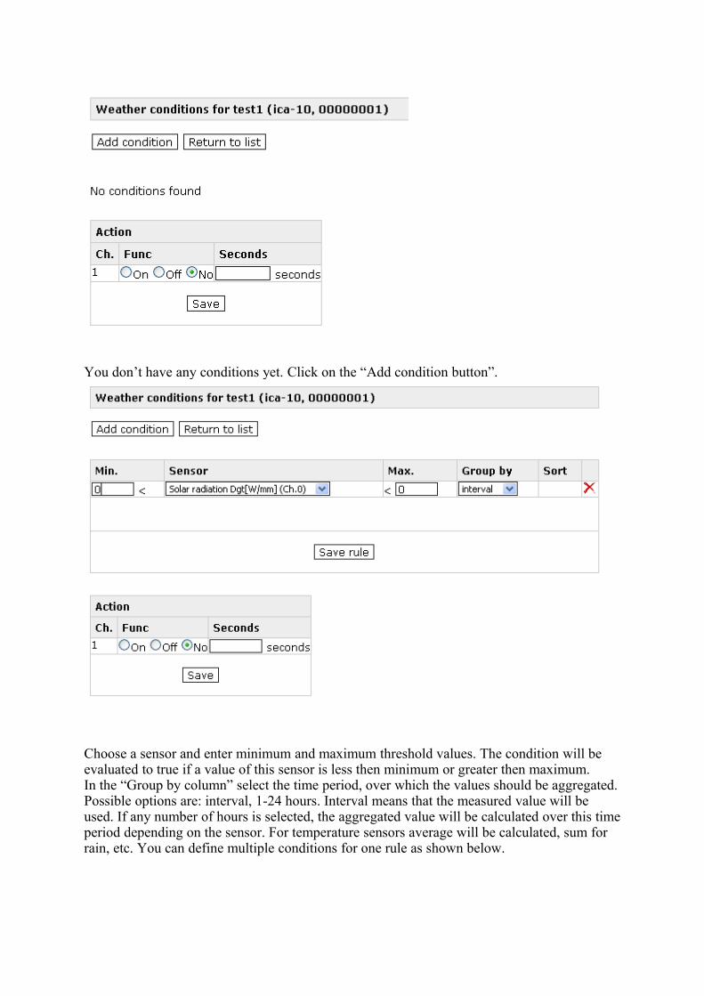
You don’t have any conditions yet. Click on the “Add condition button”.
Choose a sensor and enter minimum and maximum threshold values. The condition will be evaluated to true if a value of this sensor is less then minimum or greater then maximum. In the “Group by column” select the time period, over which the values should be aggregated. Possible options are: interval, 1-24 hours. Interval means that the measured value will be used. If any number of hours is selected, the aggregated value will be calculated over this time period depending on the sensor. For temperature sensors average will be calculated, sum for rain, etc. You can define multiple conditions for one rule as shown below.

Conditions can be joined by AND or OR functions. They are evaluated in the same order as they appear. To change the order click on or icon. Click “Save rule”.In the “Action” window below, choose the action that should be done when condition is true and click “save”. Choose “On” to switch the valve on; “Off” to switch it off; “No” to do nothing.Click “Return to list” to return to the list of rules.

5 Troubleshooting
Problem Possible reason SolutionGSM LED stays dark Battery is not connected or
dischargedCheck and connect the battery
GSM LED blinks twice cyclically No SIM card /Improper contact with SIM card
Insert SIM card properly or carefully clean contact area of SIM card
GSM LED blinks thrice cyclically PIN request is activated Deactivate PIN requestGSM LED constantly on No GSM network available / no
antenna connectedConnect antenna/Change antenna position
Status led is always on No configuration Make configuration callICA10 does not react on configuration call (not accepting the call)
Device is already configured Set back to factory settings
ICA10 does not react on configuration SMS
Wrong IMEI number in the SMS / SMS not yet delivered
Check IMEI number. / Wait until SMS is delivered
ICA10 does not react on SMS, or call, although booked to the network
The mobile phone does not transmit the phone number („Incognito“)
Activate the transmission of the phone number in your mobile phone
Both red LED´s blink consecutively
No configuration call received by ICA10
Make a configuration call

6 Technical data
• GSM: Dual Band EGSM 900/1800 MHz Compatible with ETSI GSM Phase 2+ Standard• Output power:
Class 4 (2W @ 900 MHz)Class 1 (1W @ 1800 MHz)
• Temperature range: -20°C - +55°C• Weight approx. 400 grams• Dimensions: 100x53x25 mm (l x w x h)• Supply voltage: 3.7V• Idle current: 2mA, Peak up to 500mA• Max. output voltage: 6V
HotlineIn case of technical problems or questions concerning theICA10 our hotline is available for you:Monday – Friday: 9 am – 5pmTechn. Hotline: +43 664 1521565Technical Hotline:For all other questions, please call sales+43 (0)3172 /55210Mail: [email protected]
Related Documents

![songbook - pts- · PDF fileZusammengestellt von Petzlberger Roland [Best of] Gaisbauer Otmar FRIGA Ges.m.b.H [Best of] Songbook . 1](https://static.cupdf.com/doc/110x72/5a78f8ed7f8b9a43758bfcb2/songbook-pts-von-petzlberger-roland-best-of-gaisbauer-otmar-friga-gesmbh.jpg)


