PERSONAL PA ® T35 Transmitter Wireless FM Listening System Manual and User Guide Transmitter Model PPA T35 Optional Receiver Models PPA R37, PPA R35-8 MAN 160D

Welcome message from author
This document is posted to help you gain knowledge. Please leave a comment to let me know what you think about it! Share it to your friends and learn new things together.
Transcript

PERSONAL PA® T35 TransmitterWireless FM Listening System
Manual and User Guide
Transmitter Model PPA T35Optional Receiver Models PPA R37, PPA R35-8
MAN 160D

2
PERSONAL PA® T35 Transmitter
MAN 160D

3
PERSONAL PA® T35 Transmitter
MAN 160D
PERSONAL PA® T35 Transmitter
Manual and User Guide Contents
System Overview ...............................................................................................................................................................4
Quick Setup Instructions ..................................................................................................................................................5
Detailed Installation Instructions ....................................................................................................................................6
Select a Location .............................................................................................................................................................6
Installing the Antenna .......................................................................................................................................................6
Wiring and Connections ...................................................................................................................................................7
Rear Panel .......................................................................................................................................................................7
Connecting the Power Supply ..........................................................................................................................................7
Audio Source Connections ...............................................................................................................................................7
Choosing an Audio Source for the Hearing Impaired ........................................................................................................8
Avoiding Ground Loops ....................................................................................................................................................9
Connecting to a Recording Device ...................................................................................................................................9
Controls and Features ....................................................................................................................................................10
Front Panel Controls .......................................................................................................................................................10
LCD Screen Menus ........................................................................................................................................................12
Application Presets ........................................................................................................................................................13
Bandwidth .....................................................................................................................................................................14
Frequency ......................................................................................................................................................................14
Audio Source .................................................................................................................................................................15
High Pass Filter ..............................................................................................................................................................15
Low Pass Filter ...............................................................................................................................................................16
Compressor Slope .........................................................................................................................................................16
Compressor Gain ...........................................................................................................................................................17
RF Output ......................................................................................................................................................................18
Safety Information ...........................................................................................................................................................19
Recycling Instructions ....................................................................................................................................................19
Receiver Instructions ......................................................................................................................................................20
Receiver Management ...................................................................................................................................................23
Battery Information .........................................................................................................................................................23
Trouble-Shooting Guide..................................................................................................................................................24
Warranty .............................................................................................................................................................................27
System Specifications ....................................................................................................................................................28

4
PERSONAL PA® T35 Transmitter
MAN 160D
LOUDSPEAKER
LINE-LEVEL OUTPUT
SOUND SYSTEM AMPLIFIER
MICROPHONE
PPA T35 TRANSMITTER FM RECEIVERS
A100
System OverviewThe PPA T35 is an FM Wide-Band / Narrow-Band transmitter operating in the 72-76MHz bandwidth. Compatible Williams Sound receivers include PPA R37, PPA R35-8 and the PPA R1600 remote speaker.
Developed for hearing assistance in places of public access, the PPA T35 is designed for those who need help overcoming background noise, reverberation, or distance from the sound source. It includes a complete audio processor optimized for the needs of hearing impaired persons and is easily integrated with your existing sound system. The PPA T35 can also be used with a microphone as a stand-alone system.
Your PPA T35 transmitter operates just like an FM radio station. The transmitter takes audio directly from a microphone or sound system. This audio is then broadcast over an FM radio signal. FM radios can be worn by listeners or AC powered amplified speaker with built in radio can be utilized as needed. The broadcast can be received up to 1000ft from the transmitter *. This allows listeners to sit anywhere in the area and listen to the broadcast at the level they need without disturbing others around them.
Please read through this manual carefully. It includes important setup procedures and guidelines for proper operation. If at any time you are having problems with this product, please contact Williams Sound toll free for assistance: 800-843-3544.
NOTE: FCC regulations, section 15.21, requires the user to comply with the rules of transmitter operation. Any changes or modifications made by the user not expressly approved for compliance may result in the loss of all privileges and authority to operate the equipment.
*Range is dependant upon the environment.
Figure 1: Overall System Diagram
5
PERSONAL PA® T35 Transmitter
MAN 160D
Quick Setup Instructions1. Position the PPA T35 transmitter near the sound system or mixer from which it will receive audio.
2. Install the ANT 025 whip antenna. Gently thread the ANT 025 onto the stud recessed in the hole on the top of the transmitter. The antenna length must NOT exceed 28 inches when fully extended. It was found during test that the antenna length, when the length was greater than 28 inches, the device failed the radiated emissions. It FAILED with the longer length.
3. Connect the power supply to the “Power In” connector (figure 5, page 7) located in the back of the T35. Press in the power button on the front of the T35. The “On Air” green LED indicator should illuminate. If not, go back and check the power connections.
4. Select an application. The T35 has three pre-configured Application Presets to choose from: Hearing Assist, Music and Voice. The performance of the T35 is optimized for each selected application. Using the menu control buttons on the front of the T35 (Figure 2), press the “ v ” button to access the “Application Presets” LCD screen. Press the “+” and “-” menu buttons to alternate between Hearing Assist, Music and Voice selection. When the desired Application Preset is displayed, press the “Set” button to save the change into memory.
5. Configure the T35 for the appropriate audio source. Using the menu control buttons on the front of the T35 (Figure 2), press the “ v ” button to access the “Audio Source” LCD screen. Using the “+” and “-” menu buttons (Figure 2), choose between MIC, SIMPLEX-MIC, or LINE. When the desired audio input is displayed, press the “Set” button to save the change into memory. Lastly, connect the audio source to the audio input jack in the rear of the T35 transmitter.
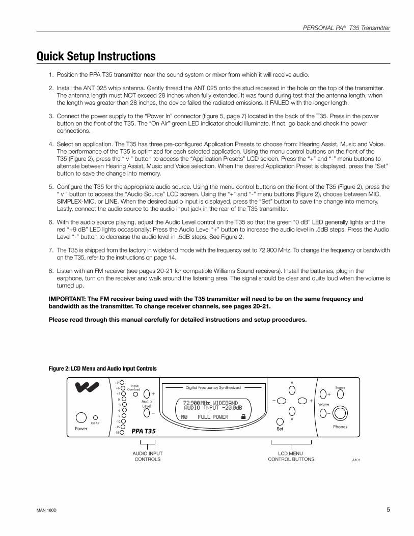
6. With the audio source playing, adjust the Audio Level control on the T35 so that the green “0 dB” LED generally lights and the red “+9 dB” LED lights occasionally: Press the Audio Level “+” button to increase the audio level in .5dB steps. Press the Audio Level “-” button to decrease the audio level in .5dB steps. See Figure 2.
7. The T35 is shipped from the factory in wideband mode with the frequency set to 72.900 MHz. To change the frequency or bandwidth on the T35, refer to the instructions on page 14.
8. Listen with an FM receiver (see pages 20-21 for compatible Williams Sound receivers). Install the batteries, plug in the earphone, turn on the receiver and walk around the listening area. The signal should be clear and quite loud when the volume is turned up.
IMPORTANT: The FM receiver being used with the T35 transmitter will need to be on the same frequency and bandwidth as the transmitter. To change receiver channels, see pages 20-21.
Please read through this manual carefully for detailed instructions and setup procedures.
Figure 2: LCD Menu and Audio Input Controls
AUDIO INPUTCONTROLS
LCD MENU CONTROL BUTTONS
–
+
V
–
–
++
V
Set
A101

6
PERSONAL PA® T35 Transmitter
MAN 160D
Remote Antenna: FCC rules allow only the use of antennas provided by Williams Sound. To use a remote antenna supplied by Williams Sound, the antenna cap may be removed by turning it counter-clockwise with a pliers or wrench. Please call customer service 800.843.3544 if you have any questions.
The external antenna impedance is 75 Ohms.
Setting up the PPA T35 - Detailed Instructions
Select a LocationThe transmitter is usually located near the sound system amplifier or mixer for easy access to an audio output signal. Position the transmitter on a level surface. It should be free from metallic objects that might interfere with the antenna signal.
For permanent installation, the PPA T35 transmitter can be rack mounted. Use the Williams Sound RPK 005 or RPK 006 rack mount kits. Make sure there is good electrical contact between the transmitter chassis and the rack cabinet.
Install the ANT 025 Whip Antenna
NOTE: If the T35 is going to be rack mounted, you will not be able to install the ANT 025 whip antenna. For rack mounting, consider installing a remote antenna (see following section).
The PPA T35 is shipped standard with a single ANT 025 whip antenna. The ANT 025 threads on to a stud recessed in a hole on the top of the transmitter. Screw the antenna clockwise until the connection is secure (Figure 3). Do not use excessive force to tighten the antenna. The antenna length must NOT exceed 28 inches when fully extended. It was found during test that the antenna length, when the length was greater than 28 inches, the device failed the radiated emissions. It FAILED with the longer length.
ANT 025 ANTENNA(INCLUDED)
ANT 005COAXIAL ANTENNA
ORANT 024 WALL MOUNT
DIPOLE ANTENNA(OPTIONAL)
A102
Figure 3: Installing the ANT 025 Antenna (rear view)

7
PERSONAL PA® T35 Transmitter
MAN 160D
NOTE: The T35 will not be activated until the power button on the front of the T35 is pressed into the “on” position.
Audio Source ConnectionsThe T35 transmitter will accept the following audio sources:
1. Balanced Microphone on a 3-pin (XLR) connector without simplex power.
2. Balanced Microphone with 12 volt simplex power (DIN 45596) on a 3-pin (XLR) connector.
3. Balanced/Unbalanced microphone without power on 1/4 inch jack
4. Balanced/Unbalanced Line on a 3-pin (XLR) connector.
5. Balanced/Unbalanced Line on 1/4 inch jack.
WARNING: The T35 is not designed to accept 70 volt speaker signals! This may result in damage to your system. The sound source should come directly from the system mixer or amplifier as an unprocessed signal.
IMPORTANT: When a suitable audio source has been selected, you MUST configure the audio source controls on the front panel of the T35.
There are three possible selections to choose from: MIC, SIMPLEX-MIC and LINE. SEE PAGE 15 FOR AUDIO SOURCE CONTROLS. After the audio source selection has been made, plug in the appropriate audio source into the “Audio Input” jack in the rear of the T35.
POWERSUPPLY
A103
Figure 4: Rear View of T35
Wiring and Connections
Power Supply Connection for U.S. ApplicationConnect the TFP 016 power supply to the “Power In” jack located on the rear of the T35 transmitter.

8
PERSONAL PA® T35 Transmitter
MAN 160D
BALANCED LINE USING 1/4" CONNECTOR
IN PHASE
A106
UNBALANCED LINE USING 1/4" CONNECTORA107
4.7 K
4.7 K
SOURCE A
SOURCE B
CONNECTING TO A MULTI-CHANNEL OR STEREO SOURCEA109
BALANCED LINE USING 3–PIN CONNECTOR
IN PHASE
1 23
3 PIN CONNECTOR
A108
IN PHASE
FROM MICROPHONE
1 23
3 PIN CONNECTOR
LOW IMPEDANCE MICROPHONEA104
UNBALANCED LINE USING 3–PIN CONNECTOR
1 23
3 PIN CONNECTOR
A105
Figure 5: Audio Source Connectors
Multi–Channel SourcesBy constructing a simple resistive mixer, stereo (or 3 channel) sources can be connected to the T35. Additional channels can be accommodated by adding a resistor for each source. Necessary resistors can be obtained from Williams Sound (Part Number RFC 472) or from any local electronics parts supplier. See Figure 5.
Selecting an Audio source Appropriate for Hearing Impaired ListenersIf the T35 is going to be used specifically for the accommodation of hearing impaired listeners, we recommend following these general guidelines:
The PPA T35 transmits audio with excellent fidelity. Therefore, the audio source signal should be of the highest audio quality and not subject to a compressor, limiter, reverberation, or other signal processing equipment. The T35 has an effective audio processor. If compression is desired in the audio, refer to page 16-17 for features and controls. Excessive compression is not helpful to the hearing impaired and can contribute to excessive noise in the receiver outputs.
The T35 audio source signal is usually connected to a mixer’s “line output” signal which is behind the mixer’s parametric equalizers but ahead of any equalization used for house loudspeakers.
If audio delay is available for use in large auditoriums, it’s usually best to use it. Because radio signals travel faster than sound, delaying the transmitted audio so that an average listener (in the middle of the listening area) hears the transmitted audio a few milliseconds after audio from the main sound reinforcement system speaker is helpful. This will also help audience members who lip read.

9
PERSONAL PA® T35 Transmitter
MAN 160D
Avoiding Hum in the Audio (as a Result of a Ground Loop)A hum created by a ground loop can often be eliminated by connecting a capacitor in series with the audio line shield to the transmitter’s ground. This method also maintains good RF shielding. Determining the effectiveness of this method for your installation usually requires some experimentation. See Figure 6.
IN PHASE
1 23
3-PINCONNECTOR
BREAKING A GROUND LOOP WHEN CONNECTING TO A UNBALANCED LINE
BREAKING A GROUND LOOP WHEN CONNECTING TO A BALANCED LINE
.01 uF CERAMIC DISC CAPACITOR .01 uF CERAMIC
DISC CAPACITOR
A110
Figure 6: Connecting to a Balance/Unbalanced Line
Figure 7: Audio Line Output
PPA T35 RECORDING DEVICE
AUDIO LINE OUT AUDIO LINE IN
A111
Connecting the T35 to a Recording DeviceUse the Audio Line Out jack for monitoring, recording, or routing processed audio to another sound system.
10
PERSONAL PA® T35 Transmitter
MAN 160D
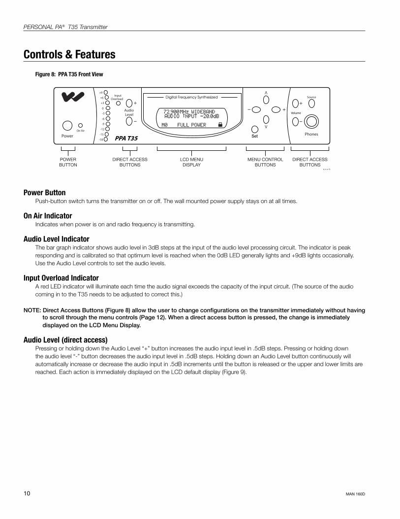
Power ButtonPush-button switch turns the transmitter on or off. The wall mounted power supply stays on at all times.
On Air IndicatorIndicates when power is on and radio frequency is transmitting.
Audio Level IndicatorThe bar graph indicator shows audio level in 3dB steps at the input of the audio level processing circuit. The indicator is peak responding and is calibrated so that optimum level is reached when the 0dB LED generally lights and +9dB lights occasionally. Use the Audio Level controls to set the audio levels.
Input Overload IndicatorA red LED indicator will illuminate each time the audio signal exceeds the capacity of the input circuit. (The source of the audio coming in to the T35 needs to be adjusted to correct this.)
NOTE: Direct Access Buttons (Figure 8) allow the user to change configurations on the transmitter immediately without having to scroll through the menu controls (Page 12). When a direct access button is pressed, the change is immediately displayed on the LCD Menu Display.
Audio Level (direct access)Pressing or holding down the Audio Level “+” button increases the audio input level in .5dB steps. Pressing or holding down the audio level “-” button decreases the audio input level in .5dB steps. Holding down an Audio Level button continuously will automatically increase or decrease the audio input in .5dB increments until the button is released or the upper and lower limits are reached. Each action is immediately displayed on the LCD default display (Figure 9).
POWERBUTTON
DIRECT ACCESSBUTTONS
DIRECT ACCESSBUTTONS
LCD MENUDISPLAY
MENU CONTROLBUTTONS
–
+
V
–
–
++
V
Set
A112
Figure 8: PPA T35 Front View
Controls & Features
11
PERSONAL PA® T35 Transmitter
MAN 160D
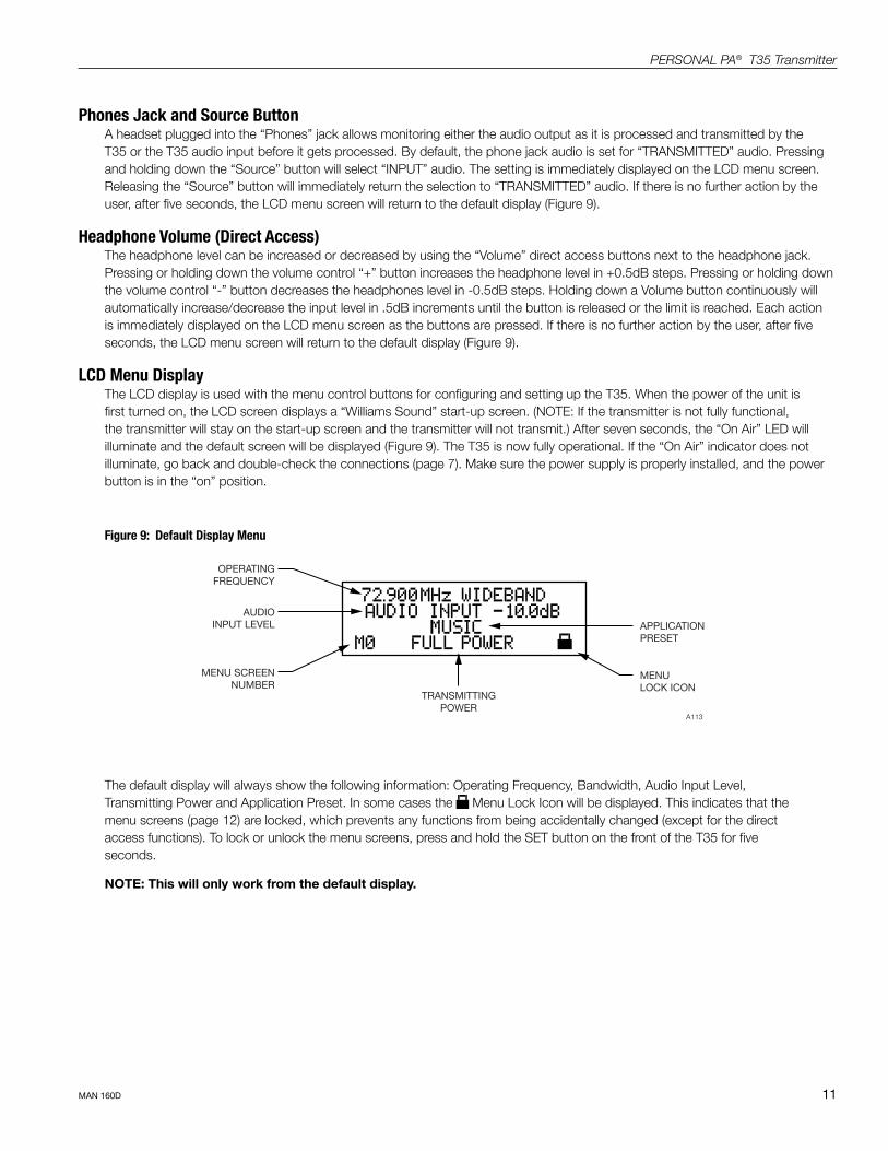
OPERATINGFREQUENCY
AUDIOINPUT LEVEL
MENU SCREENNUMBER
TRANSMITTINGPOWER
MENULOCK ICON
APPLICATIONPRESET
A113
Phones Jack and Source ButtonA headset plugged into the “Phones” jack allows monitoring either the audio output as it is processed and transmitted by the T35 or the T35 audio input before it gets processed. By default, the phone jack audio is set for “TRANSMITTED” audio. Pressing and holding down the “Source” button will select “INPUT” audio. The setting is immediately displayed on the LCD menu screen. Releasing the “Source” button will immediately return the selection to “TRANSMITTED” audio. If there is no further action by the user, after five seconds, the LCD menu screen will return to the default display (Figure 9).
Headphone Volume (Direct Access)The headphone level can be increased or decreased by using the “Volume” direct access buttons next to the headphone jack. Pressing or holding down the volume control “+” button increases the headphone level in +0.5dB steps. Pressing or holding down the volume control “-” button decreases the headphones level in -0.5dB steps. Holding down a Volume button continuously will automatically increase/decrease the input level in .5dB increments until the button is released or the limit is reached. Each action is immediately displayed on the LCD menu screen as the buttons are pressed. If there is no further action by the user, after five seconds, the LCD menu screen will return to the default display (Figure 9).
LCD Menu DisplayThe LCD display is used with the menu control buttons for configuring and setting up the T35. When the power of the unit is first turned on, the LCD screen displays a “Williams Sound” start-up screen. (NOTE: If the transmitter is not fully functional, the transmitter will stay on the start-up screen and the transmitter will not transmit.) After seven seconds, the “On Air” LED will illuminate and the default screen will be displayed (Figure 9). The T35 is now fully operational. If the “On Air” indicator does not illuminate, go back and double-check the connections (page 7). Make sure the power supply is properly installed, and the power button is in the “on” position.
Figure 9: Default Display Menu
The default display will always show the following information: Operating Frequency, Bandwidth, Audio Input Level, Transmitting Power and Application Preset. In some cases the Menu Lock Icon will be displayed. This indicates that the menu screens (page 12) are locked, which prevents any functions from being accidentally changed (except for the direct access functions). To lock or unlock the menu screens, press and hold the SET button on the front of the T35 for five seconds.
NOTE: This will only work from the default display.
12
PERSONAL PA® T35 Transmitter
MAN 160D
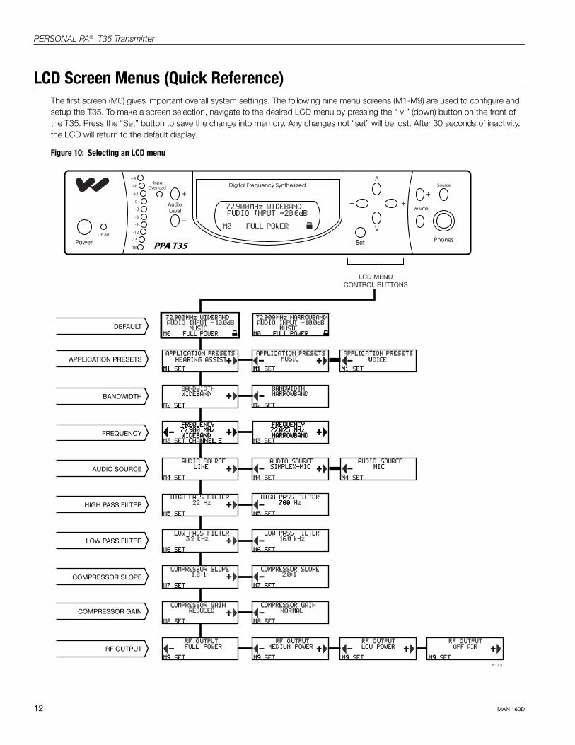
DEFAULT
AUDIO SOURCE
HIGH PASS FILTER
LOW PASS FILTER
COMPRESSOR SLOPE
COMPRESSOR GAIN
RF OUTPUT
FREQUENCY
BANDWIDTH
APPLICATION PRESETS
LCD MENUCONTROL BUTTONS
–
+
V
–
–
++
V
Set
A114
Figure 10: Selecting an LCD menu
LCD Screen Menus (Quick Reference)The first screen (M0) gives important overall system settings. The following nine menu screens (M1-M9) are used to configure and setup the T35. To make a screen selection, navigate to the desired LCD menu by pressing the “ v ” (down) button on the front of the T35. Press the “Set” button to save the change into memory. Any changes not “set” will be lost. After 30 seconds of inactivity, the LCD will return to the default display.
13
PERSONAL PA® T35 Transmitter
MAN 160D
LCD Screen Menus (Detailed)
Application Presets (M1)The Application Presets screen allows the user to quickly and easily configure the T35 for common applications. In some cases, the Application Presets will be the only setup needed for properly configuring the T35 transmitter.
There are three Application Presets to choose from: Hearing Assist, Music and Voice. When one of these selections is “set,” the performance of the T35 is immediately optimized for the needs of that application (an adjustment is automatically made to the Low/High Pass Filter, and Compressor Slope control). Refer to the chart below for a comparison of the Application Preset configurations.
By default, the T35 is shipped in the Music mode. For music, concerts, and other applications where the highest audio quality is desirable, Music is the recommended mode of operation. For hearing assistance applications, or applications where the message is critical for listening, Hearing Assist is the recommended mode of operation. For speaking and other voice applications, Voice is the preferred mode of operation.
To select an Application Preset:
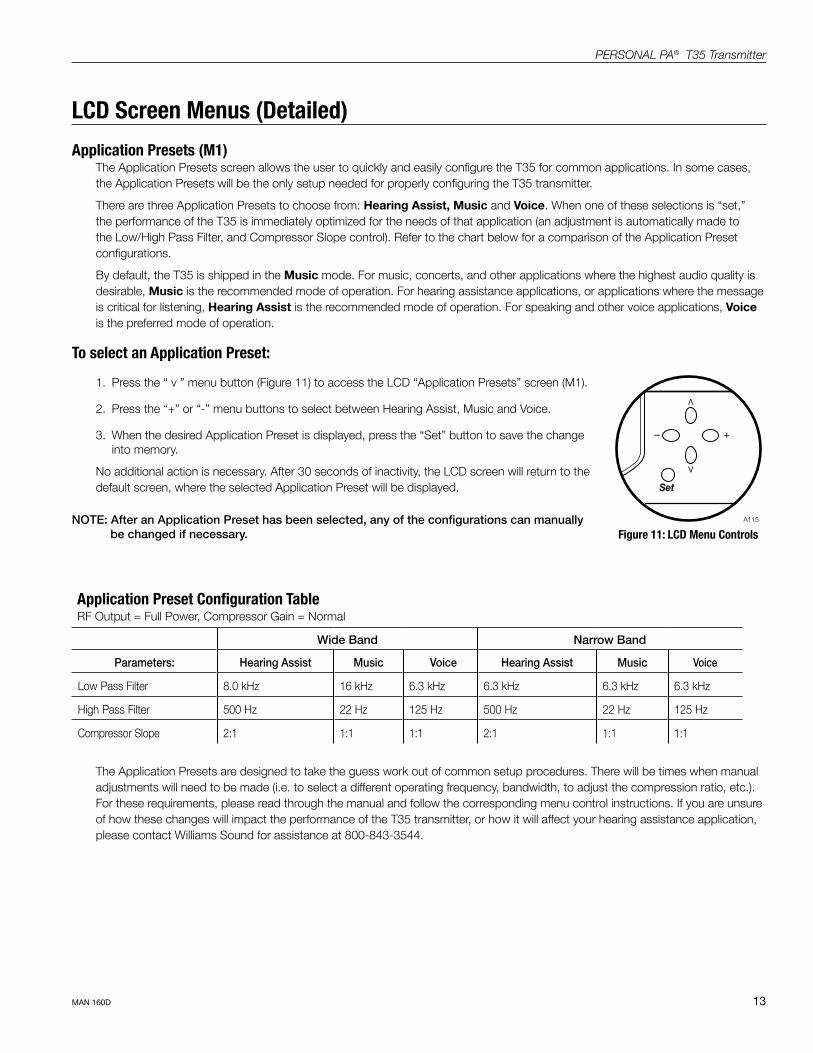
1. Press the “ v ” menu button (Figure 11) to access the LCD “Application Presets” screen (M1).
2. Press the “+” or “-” menu buttons to select between Hearing Assist, Music and Voice.
3. When the desired Application Preset is displayed, press the “Set” button to save the change into memory.
No additional action is necessary. After 30 seconds of inactivity, the LCD screen will return to the default screen, where the selected Application Preset will be displayed.
NOTE: After an Application Preset has been selected, any of the configurations can manually be changed if necessary.
Application Preset Configuration TableRF Output = Full Power, Compressor Gain = Normal
Wide Band Narrow Band
Parameters: Hearing Assist Music Voice Hearing Assist Music Voice
Low Pass Filter 8.0 kHz 16 kHz 6.3 kHz 6.3 kHz 6.3 kHz 6.3 kHz
High Pass Filter 500 Hz 22 Hz 125 Hz 500 Hz 22 Hz 125 Hz
Compressor Slope 2:1 1:1 1:1 2:1 1:1 1:1
The Application Presets are designed to take the guess work out of common setup procedures. There will be times when manual adjustments will need to be made (i.e. to select a different operating frequency, bandwidth, to adjust the compression ratio, etc.). For these requirements, please read through the manual and follow the corresponding menu control instructions. If you are unsure of how these changes will impact the performance of the T35 transmitter, or how it will affect your hearing assistance application, please contact Williams Sound for assistance at 800-843-3544.
Figure 11: LCD Menu Controls
V
– +
V
Set
A115
14
PERSONAL PA® T35 Transmitter
MAN 160D
Bandwidth (M2)The default LCD menu screen (as shown on page 11, Figure 9) will always display the user selected bandwidth as “Wideband” or “Narrowband.” The T35 is shipped from the factory in Wideband mode. First determine the bandwidth of the associated receiver, then set the T35 to that bandwidth:
1. Press the “ v ” menu button (Figure 11) to access the LCD “Bandwidth” (M2) screen.
2. Press the “+” or “-” menu buttons to select between Narrowband and Wideband.
3. When the desired bandwidth is displayed, press the “Set” button to save the change into memory.
No additional action is necessary. After 30 seconds of inactivity, the LCD screen will return to the default screen, where the selected bandwidth will be displayed.
Frequency (M3)First determine the bandwidth and frequency of the associated receiver, then set the T35 to that bandwidth (see above) and frequency:
Available Frequencies:
If the wideband operation is selected, 17 wideband frequencies are available:
72.100 (CH A), 72.300 (CH B), 72.500 (CH C), 72.700 (CH D), 72.900 (CH E), 74.700 (CH I), 75.300 (CH J), 75.500 (CH F),
75.700 (CH G), 75.900 MHz (CH H), 72.200 (CH K), 72.400 (CH N), 72.600 (CH 0), 72.800 (CH P), 75.400 (CH R), 75.600 (CH S),
75.800 (CH T).
If the narrowband operation is selected, 77 narrowband frequencies are available:
72.025, 72.050, 72.075, 72.100, 72.125, 72.150, 72.175, 72.200, 72.225, 72.250, 72.275, 72.300, 72.325, 72.350, 72.375, 72.400,
72.425, 72.450, 72.475, 72.500, 72.525, 72.550, 72.575, 72.600, 72.625, 72.650, 72.675, 72.700, 72.725, 72.750, 72.775, 72.800,
72.825, 72.850, 72.875, 72.900, 72.925, 72.950, 72.975, 74.625, 74.650, 74.675, 74.700, 74.725, 74.750, 74.775, 75.225, 75.250,
75.275, 75.300, 75.325, 75.350, 75.375, 75.400, 75.425, 75.450, 75.475, 75.500, 75.525, 75.550, 75.575, 75.600, 75.625, 75.650,
75.675, 75.700, 75.725, 75.750, 75.775, 75.800, 75.825, 75.850, 75.875, 75.900, 75.925, 75.950, and 75.975 MHz.
The T35 is shipped from the factory with the frequency pre-set to wideband (CH E) 72.900 MHz. To change the frequency:
1. Press the “ v ” menu button to select the LCD “Frequency” (M3) screen.
2. To increase the frequency, press the “+” menu button. To decrease the frequency, press the “-” menu button.
3. Holding down the “+” or “-” menu buttons will change the frequency automatically until the highest or lowest available frequency has been met.
When the desired frequency is displayed, press the “Set” button to save the change into memory.
No additional action is necessary. A new adjustment may now be made, or after 30 seconds of inactivity, the LCD screen will return to the default screen, where the selected frequency will be displayed.
NOTE: The T35 will not broadcast on the newly selected frequency until the “set” button has been pressed.
REMINDER: If the lock icon is displayed on the default display, the menu screens are locked, and you will not be able to make changes. To unlock the menu screens, refer to the instructions on page 11.
15
PERSONAL PA® T35 Transmitter
MAN 160D
Audio Source (M4)The Audio Source control menu is used to configure the T35 for a proper audio source connection. The transmitter will accept the following audio sources:
1. Balanced Microphone on a 3-pin (XLR) connector without simplex power.
2. Balanced Microphone with 12 volt simplex power (DIN 45596) on a 3-pin (XLR)�connector.
3. Balanced/Unbalanced microphone without power on 1/4 inch jack
4. Balanced/Unbalanced Line on a 3-pin (XLR)�connector.
5. Balanced/Unbalanced Line on 1/4 inch jack.
The Audio Source menu has three possible selections to choose from: MIC, SIMPLEX-MIC, or LINE.
To select the audio input:1. Press the “ v ” menu button (Figure 11) to access the LCD “Audio Source” (M4) screen.
2. Press the “+” or “-” menu buttons to select between MIC, SIMPLEX-MIC, or LINE.
3. When the desired audio input is displayed, press the “Set” button to save the change into memory.
No additional action is necessary. After 30 seconds of inactivity, the LCD screen will return to the default display.
High Pass Filter (M5)The high pass filter will help to remove low frequency “noise” from the transmitted audio signal. This is typically used when there is room noise, a line hum, or breath accents picked up from an improperly installed microphone.
To select a High Pass Filter cutoff frequency:1. Press the down “ v ” menu button (Figure 11) to select the LCD “High Pass Filter” (M5) screen.
2. Press the “+” menu button to increase the cutoff frequency. Each time the “+” button is pressed, the cutoff frequency will be raised by 1/2 octave. This can be repeated until the cutoff frequency reaches the maximum 700 Hz.
Press the “-” menu button to decrease the cutoff frequency. Each time the “-” button is pressed, the cutoff frequency will be lowered by 1/2 octave. This can be repeated until the cutoff frequency reaches the minimum 22 Hz.
3. When the desired cutoff frequency is displayed, press the “Set” button to save the change into memory.
No additional action is necessary. After 30 seconds of inactivity, the LCD screen will return to the default display.
IMPORTANT: Listen to the transmitted audio through the headphone jack, especially when deciding on an appropriate high pass filter. This is a good way to ensure the listening audience is going to receive the highest audio quality.
16
PERSONAL PA® T35 Transmitter
MAN 160D
Low Pass Filter (M6)The low pass filter will help to remove high frequency “noise” from the transmitted audio signal. This is typically used when there is a hiss in the audio line as a result of room noise, speech sibilants, or other high frequency unpleasantries.
To select a Low Pass Filter cutoff frequency:1. Press the down “ v ” menu button (Figure 11) to select the LCD “Low Pass Filter” (M6) screen.
2. Press the “+” menu button to increase the cutoff frequency selection. The cutoff frequency can be increased to a maximum of 16.0 kHz.
Press the “-” menu button to decrease the cutoff frequency selection. The cutoff frequency can be decreased to a minimum of 3.2 kHz.
3. When the desired cutoff frequency is displayed, press the “Set” button to save the change into memory.
No additional action is necessary. After 30 seconds of inactivity, the LCD screen will return to the default display.
Compressor Slope (M7)
Compression is typically used for voice and hearing assistance applications. It reduces the dynamic range: For a listener who has difficulty hearing the quiet sounds of an audio broadcast, compression will boost the quiet sounds to louder listening levels. For listening to music programs, concerts, etc., lower compression ratios or no compression is generally used.
The Compressor Slope has the following selectable compression ratios:1:1 and 2:1
NOTE: The T35 is shipped from the factory at a 1:1 compression ratio (no compression).
To select a compression ratio:1. Press the “ v ” menu button (Figure 11) to select the LCD “Compressor Slope” (M7) screen.
2. Press the “+” menu button to increase the compression to 2:1. This produces generally loud out put, even at very low audio level signals.
Press the left “-” menu button to decrease the compression to 1:1, which is no compression.
3. When the desired compression ratio is displayed, press the “Set” button to save the change into memory. No additional action is necessary.
NOTE: The installer of the T35 needs to take care in using compression, because some hearing impaired people cannot tolerate as loud of a sound as those with normal hearing.
IMPORTANT: Listen to the transmitted audio through the headphone jack, especially when deciding on an appropriate high pass filter. This is a good way to ensure the listening audience is going to receive the highest audio quality.
17
PERSONAL PA® T35 Transmitter
MAN 160D
Compressor Gain (M8)The T35 has two selectable modes of compressor gain: Normal and Reduced. For applications such as music and voice, where high audio quality is desirable, Reduced is the recommended mode of operation. Reduced compression gain minimizes the amount of low input level boost and alteration in the sound which compression can cause.
For hearing assistance or applications where the transmitting message is critical for listening, the T35 can be set to Normal Compression gain. Normal compression gain boosts the “soft” audio sounds for a more understandable, consistent delivery. This may be appropriate for applications where the listening audience has moderate to severe hearing loss. Compression is generally not desirable for applications such as music, concerts, etc. In this case, compression can be turned off by setting the compression “slope” to 1:1.
NOTE: The T35 is shipped from the factory in the Reduced mode.
To select Reduced or Normal Compression:1. Press the “ v ” menu button (Figure 11) to access the LCD “Compressor Gain” (M8) screen.
2. Press the “+” or “-” menu buttons to select between Reduced and Normal compressor gain.
3. When the desired compressor gain is displayed, press the “Set” button to save the change into memory.
No additional action is necessary. After 30 seconds of inactivity, the LCD screen will return to the default display.
NOTE: The installer must take care in using compression. Compression may contribute to excessive noise in the listener’s receivers.
IMPORTANT: Listen to the transmitted audio through the headphone jack, especially when deciding on an appropriate high pass filter. This is a good way to ensure the listening audience is going to receive the highest audio quality.
18
PERSONAL PA® T35 Transmitter
MAN 160D
RF Output (M9)The T35 has three selectable transmitter power levels: FULL, MEDIUM, LOW POWER, or OFF AIR. By default the T35 is set to “Full” power mode. For general listening applications, FULL power is the preferred mode of operation. “Full power” provides the T35 with an operating range of up to 1000 ft.
For special listening applications, it may be desirable to reduce the overall operating range on the T35 if: 1) The audio transmission is to be contained to a “smaller” listening area; 2) The signal is too strong and it is overloading the receiver; or 3) Multiple T35 transmitters are used in adjacent classrooms where the FM signals overlap each other. In these cases, the power level on the T35 can be reduced to MEDIUM or LOW. The RF output may be set to OFF AIR (no power) to help troubleshoot interfering or overlapping RF signals.
To select a power level:1. Press the “ v ” menu button (Figure 12) to access the “RF Output” (M9) screen.
2. Press the “+” and “-” menu button to select between: FULL POWER, MEDIUM POWER, LOW POWER and OFF AIR.
3. When the desired power level is displayed, press the “Set” button to save the change into memory.
No additional action is necessary. After 30 seconds of inactivity, the LCD screen will return to the default display, where the selected power level will be displayed.
19
PERSONAL PA® T35 Transmitter
MAN 160D
Receiver Safety Information
HEARING SAFETY
CAUTION!This product is designed to amplify sounds to a high volume level which could potentially cause hearing damage if used improperly. To protect your hearing and the hearing of others:
1. Make sure the volume is turned down before putting on the earphone or headphone before adjusting the volume to a comfortable level.
2. Set the volume level at the minimum setting that you need to hear.
3. If you experience feedback (a squealing or howling sound), reduce the volume setting and move the microphone away from the earphone or headphone.
4. Do not allow children or other unauthorized persons to have access to this product.
BATTERY SAFETY AND DISPOSAL
CAUTION!This product may be supplied with alkaline batteries. Do not attempt to recharge alkaline batteries, which may explode, release dangerous chemicals, cause burns, or other serious harm to the user or product.
PACEMAKER SAFETY
CAUTION!1. Before using this product with a pacemaker or other medical device, consult your physician or the manufacturer of your
pacemaker or other medical device.
2. If you have a pacemaker or other medical device, make sure that you are using this product in accordance with safety guidelines established by your physician or the pacemaker manufacturer.
Recycling InstructionsHelp Williams Sound protect the environment! Please take the time to dispose of your equipment properly.
Product Recycling:Please do NOT dispose of your Williams Sound equipment in the household trash. Please take the equipment to a electronics recycling center; OR return the product to the factory for proper disposal.
Battery Recycling:Please do NOT dispose of used batteries in the household trash. Please take the batteries to a retail or community collection point for recycling.
20
PERSONAL PA® T35 Transmitter
MAN 160D
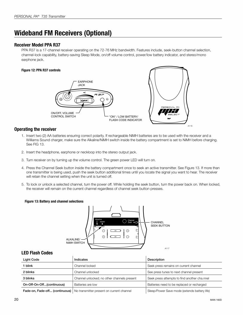
Operating the receiver1. Insert two (2) AA batteries ensuring correct polarity. If rechargeable NiMH batteries are to be used with the receiver and a
Williams Sound charger, make sure the Alkaline/NiMH switch inside the battery compartment is set to NiMH before charging. See FIG 13.
2. Insert the headphone, earphone or neckloop into the stereo output jack.
3. Turn receiver on by turning up the volume control. The green power LED will turn on.
4. Press the Channel Seek button inside the battery compartment once to seek an active transmitter. See Figure 13. If more than one transmitter is being used, push the seek button additional times until you locate the signal you want to hear. The receiver will retain the channel setting when the unit is turned off.
5. To lock or unlock a selected channel, turn the power off. While holding the seek button, turn the power back on. When locked, the receiver will remain on the current channel regardless of channel seek button presses.
Wideband FM Receivers (Optional)
Receiver Model PPA R37PPA R37 is a 17-channel receiver operating on the 72-76 MHz bandwidth. Features include, seek-button channel selection, channel-lock capability, battery-saving Sleep Mode, on/off volume control, power/low battery indicator, and stereo/mono earphone jack.
ON/OFF, VOLUME CONTROL SWITCH
EARPHONE JACK
"ON" / LOW BATTERY/FLASH CODE INDICATOR
OFF
A116
Figure 12: PPA R37 controls
LED Flash CodesLight Code Indicates Description
1 blink Channel locked Seek press remains on current channel
2 blinks Channel unlocked See press tunes to next channel present
3 blinks Channel unlocked; no other channels present Seek press attempts to find another cha.nnel
On-Off-On-Off...(continuous) Batteries are low Batteries need to be replaced or recharged
Fade-on, Fade-off... (continuous) No transmitter present on current channel Sleep/Power Save mode (extends battery life)
Figure 13: Battery and channel selections
ALKALINE/NiMH SWITCH
CHANNELSEEK BUTTON
AA
AA
–
+
+
–
ChannelSeek
A117

21
PERSONAL PA® T35 Transmitter
MAN 160D
Receiver Model PPA R35-8The PPA R35-8 is an eight channel receiver, operating on 72-76 MHz bandwidth. It features a channel selection knob, on/off volume control, LED power and low battery indicator, and an earphone jack (See Figure 14).
ON/OFF, VOLUME CONTROL SWITCH
HEADPHONEJACK
"ON"/LOWBATTERY
INDICATOR
CHANNELSELECTOR KNOB
A118
Figure 14: PPA R35-8 controls
Battery InstallationInstall two (2) AA alkaline or NiMH rechargeable batteries. Open the battery compartment by lifting the tab on the back of the receiver with a finger. To remove depleted batteries, pull up on the fabric strip. IMPORTANT: If Alkaline (non-rechargeable) batteries are being installed, slide the battery selection switch above the battery compartment to the “Alkaline” position. If installing NiMH (or rechargeable) batteries, slide the battery selection switch to the “NiMH” position. Press the batteries into place over the fabric strip. Be sure to observe proper polarity (+/-). Damage due to improper battery installation may void the warranty on the product. Close the battery door. When the sound becomes weak or distorted, replace or recharge the batteries. NOTE: The “ON” indicator on top of the unit will flash to indicate low battery.
Connecting EarphonesPlug the earphone into the “EAR” jack on the top of the unit. Only monophonic earphones will operate properly. If stereo headphones are used, sound will be heard only in one side. Williams Sound evaluates each earphone and headphone used with the PPA R35-8 receiver; we can only assure optimum performance when Williams Sound earphones and headphones are used.
Operating the ReceiverTurn the receiver on by rotating the Volume control knob. The ON indicator should illuminate RED. Refer to the channel selection chart in Figure 15 to choose from 8 standard frequencies. Turn the channel selector knob to the desired channel. IMPORTANT: Make sure the receiver frequency matches the transmitter frequency! Adjust the volume to a comfortable listening level. To turn the receiver off, rotate the Volume control knob to the left until it clicks off. The ON indicator should not be lit. To prolong the battery life of the unit, turn the receiver off when it is not in use.
Figure 15: Channel selection chart FREQUENCY (MHz) WIDEBAND CHANNEL R35-8 SWITCH SELECTION
72.1 A 1
72.2 K
72.3 B 2
72.4 N
72.5 C
72.6 O 3
72.7 D
72.8 P 4
72.9 E
74.7 I 5
75.3 J
75.4 R 6
75.5 F
75.6 S
75.7 G 7
75.8 T
75.9 H 8

22
PERSONAL PA® T35 Transmitter
MAN 160D
Belt Clip Installation for PPA R37 and PPA R35-8To Install:Position the belt clip on the rear of the PPA R37 and PPA R35-8 receivers as shown in Figure 16. Turn the belt clip 180º left or right as shown in Figure 19. The belt clip is now installed and ready for use.
To Remove:Turn the belt clip 180º so the edge points toward the top of the unit as shown in Figure 16. Gently pull the belt clip away from the unit to remove.
Figure 16: Belt Clip Installation and Removal
A119
Earpad Cleaning for Earphones and HeadphonesDo not immerse the earphone in water or other cleaning agent. Foam pads may be removed and washed with a mild laundry soap solution, rinsed thoroughly, and air dried. You may also opt to purchase new foam pads.
Call Customer Service for ordering information: 1-800-843-3544

23
PERSONAL PA® T35 Transmitter
MAN 160D
Suggestions For Receiver Management Different types of facilities use varying approaches to receiver management and earphone sanitation. Following are some options that customers have used successfully:
1. Regular users purchase or are given their own receiver and also take care of their own batteries and earphones.
2. The facility labels a receiver and earphone for each regular user. The facility maintains the units.
3. Ushers issue receivers to people who request them.
4. Earphones are sanitized after use. Foam ear cushions can be replaced or washed with a mild detergent, rinsed thoroughly and air-dried. The EAR 022 Surround Earphone can be sanitized with an alcohol pad.
5. The receivers can be stored in a multiple compartment storage case with a credit card or driver’s license left as collateral for the receiver.
6. Regular users purchase their own earphone or headphone and bring them to use with receivers at the facility.
Receiver Battery Information (all receiver models)If the receiver sound becomes weak or distorted, replace the battery. The indicator light may remain on, even with a battery that is weak. Do not leave dead batteries in the receivers. The chart below shows typical battery life with Williams Sound’s 72-76 MHz receivers:
!! IMPORTANT WARNINGS !!DO NOT ATTEMPT TO RECHARGE ZINC CARBON (“HEAVY DUTY”), ALKALINE, OR LITHIUM BATTERIES!
DO NOT ATTEMPT TO RECHARGE SINGLE-USE BATTERIES!
These batteries may heat up and explode, causing possible injury and damage to the equipment. Avoid short-ing the plus and minus battery terminals together with metal objects. Battery damage and burns can result! Use only Williams Sound supplied chargers and rechargeable batteries!
Model Battery Type Battery Life
PPA R37 and Alkaline AA Batteries (BAT 001) 50 hours
PPA R35-8 Rechargeable AA NiMH (BAT 026) 32 hours
Battery Charger InformationIMPORTANT: Batteries installed in the receiver may only be charged if they are NiMH batteries, and only if a Williams Sound charger is used. Make sure the receiver is turned off during charging! Use the chart below to select a charger for your Williams Sound 72-76 MHz receiver.
Model Charger
PPA R37 and PPA R35-8 Recharge batteries only with the CHG 3512 Multi-Charger unit. For additional charging instructions, refer to the manual included with the charger unit.
24
PERSONAL PA® T35 Transmitter
MAN 160D
Troubleshooting
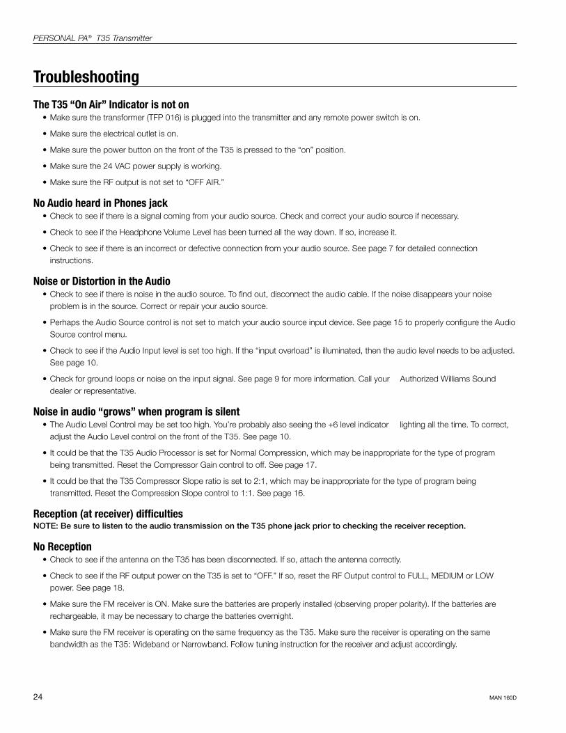
The T35 “On Air” Indicator is not on• Make sure the transformer (TFP 016) is plugged into the transmitter and any remote power switch is on.
• Make sure the electrical outlet is on.
• Make sure the power button on the front of the T35 is pressed to the “on” position.
• Make sure the 24 VAC power supply is working.
• Make sure the RF output is not set to “OFF AIR.”
No Audio heard in Phones jack • Check to see if there is a signal coming from your audio source. Check and correct your audio source if necessary.
• Check to see if the Headphone Volume Level has been turned all the way down. If so, increase it.
• Check to see if there is an incorrect or defective connection from your audio source. See page 7 for detailed connection instructions.
Noise or Distortion in the Audio• Check to see if there is noise in the audio source. To find out, disconnect the audio cable. If the noise disappears your noise
problem is in the source. Correct or repair your audio source.
• Perhaps the Audio Source control is not set to match your audio source input device. See page 15 to properly configure the Audio Source control menu.
• Check to see if the Audio Input level is set too high. If the “input overload” is illuminated, then the audio level needs to be adjusted. See page 10.
• Check for ground loops or noise on the input signal. See page 9 for more information. Call your Authorized Williams Sound dealer or representative.
Noise in audio “grows” when program is silent• The Audio Level Control may be set too high. You’re probably also seeing the +6 level indicator lighting all the time. To correct,
adjust the Audio Level control on the front of the T35. See page 10.
• It could be that the T35 Audio Processor is set for Normal Compression, which may be inappropriate for the type of program being transmitted. Reset the Compressor Gain control to off. See page 17.
• It could be that the T35 Compressor Slope ratio is set to 2:1, which may be inappropriate for the type of program being transmitted. Reset the Compression Slope control to 1:1. See page 16.
Reception (at receiver) difficultiesNOTE: Be sure to listen to the audio transmission on the T35 phone jack prior to checking the receiver reception.
No Reception • Check to see if the antenna on the T35 has been disconnected. If so, attach the antenna correctly.
• Check to see if the RF output power on the T35 is set to “OFF.” If so, reset the RF Output control to FULL, MEDIUM or LOW power. See page 18.
• Make sure the FM receiver is ON. Make sure the batteries are properly installed (observing proper polarity). If the batteries are rechargeable, it may be necessary to charge the batteries overnight.
• Make sure the FM receiver is operating on the same frequency as the T35. Make sure the receiver is operating on the same bandwidth as the T35: Wideband or Narrowband. Follow tuning instruction for the receiver and adjust accordingly.

25
PERSONAL PA® T35 Transmitter
MAN 160D
Insufficient range, good reception near transmitter, poor at a distance• Check to see if the transmitting antenna was installed incorrectly. If so, correct or replace the antenna. The signal should be clearly
audible up to at least a 100-foot distance with the ANT 005 or ANT 025.
• Make sure the transmitting antenna is not in an unsuitable location. Perhaps the transmitting antenna was installed inside a metal enclosure or is separated from the reception area by electrically conducting objects. (i.e., steel stud walls, heating ducts, substantial structural steel, or 2x2 or 2x4 ceiling grid.) In either case, reinstall the antenna according to installation instructions, locating it outside metal enclosures and away from electrically conducting objects.
• Perhaps there is a strong interfering signal. If so, make sure the transmitter and antenna are correctly installed. Set the transmitter to FULL power output. If this does not solve the problem, try operating the transmitter on a different frequency. If operating the T35 in wideband mode, try switching to narrow band operation (see page 14). Narrowband operation is more resistant to outside interference.
Users must turn receiver volume controls way up (to 4 or 5) to get enough volume• Perhaps there is insufficient audio level. If so, the audio level indicator will read too low because the audio level control is set
incorrectly on the transmitter. Correct the Audio Level control setting. See page 10.
• It could be that the audio input is not configured for the audio source being used. If not, correct the setting of the Audio Source control menu. See page 15.
• Some users may not be helped by this system. Severe hearing loss may require using the system with a telecoil coupler (i.e., Neckloop) and personal hearing aid.
• Check your batteries. For non-rechargeable (alkaline) batteries, they may need replaced. If you are using rechargeable batteries, make sure the batteries are fully charged prior to use.
Users complain of too much noise during soft audio. Dynamic range of music reduced too greatly.• Check to see if the Audio Level control is set too high. This problem is more likely to occur in Normal Compression mode, but can
also occur in Reduced Compression mode. To reduce this noise, adjust the Audio Level, carefully noting the Level Indicator. The +6 LED should light occasionally.
• Perhaps the transmitter is set for Normal Compression when Reduced Compression would be more suitable, given the program material. If so, set the Compressor Gain control to Reduced Compression. See page 17.
26
PERSONAL PA® T35 Transmitter
MAN 160D
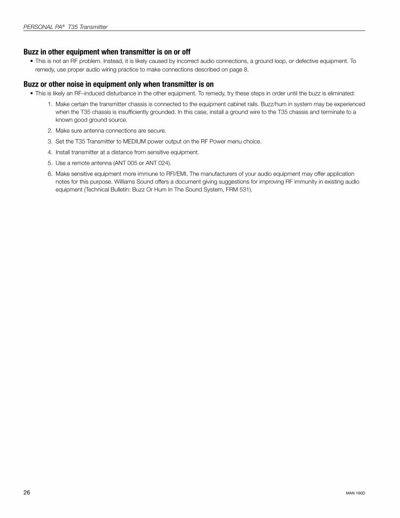
Buzz in other equipment when transmitter is on or off• This is not an RF problem. Instead, it is likely caused by incorrect audio connections, a ground loop, or defective equipment. To
remedy, use proper audio wiring practice to make connections described on page 8.
Buzz or other noise in equipment only when transmitter is on• This is likely an RF–induced disturbance in the other equipment. To remedy, try these steps in order until the buzz is eliminated:
1. Make certain the transmitter chassis is connected to the equipment cabinet rails. Buzz/hum in system may be experienced when the T35 chassis is insufficiently grounded. In this case, install a ground wire to the T35 chassis and terminate to a known good ground source.
2. Make sure antenna connections are secure.
3. Set the T35 Transmitter to MEDIUM power output on the RF Power menu choice.
4. Install transmitter at a distance from sensitive equipment.
5. Use a remote antenna (ANT 005 or ANT 024).
6. Make sensitive equipment more immune to RFI/EMI. The manufacturers of your audio equipment may offer application notes for this purpose. Williams Sound offers a document giving suggestions for improving RF immunity in existing audio equipment (Technical Bulletin: Buzz Or Hum In The Sound System, FRM 531).
27
PERSONAL PA® T35 Transmitter
MAN 160D
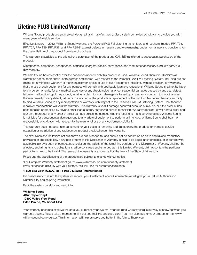
Lifetime PLUS Limited WarrantyWilliams Sound products are engineered, designed, and manufactured under carefully controlled conditions to provide you with many years of reliable service.
Effective January 1, 2012, Williams Sound warrants the Personal PA® FM Listening transmitters and receivers (models PPA T35, PPA T27, PPA T36, PPA R37, and PPA R35-8) against defects in materials and workmanship under normal use and conditions for the useful lifetime of the product from date of purchase.
This warranty is available to the original end purchaser of the product and CAN BE transferred to subsequent purchasers of the product.
Microphones, earphones, headphones, batteries, chargers, cables, carry cases, and most other accessory products carry a 90-day warranty.
Williams Sound has no control over the conditions under which this product is used. Williams Sound, therefore, disclaims all warranties not set forth above, both express and implied, with respect to the Personal PA® FM Listening System, including but not limited to, any implied warranty of merchantability or fitness of use of such equipment including, without limitation, any warranty that the use of such equipment for any purpose will comply with applicable laws and regulations. Williams Sound shall not be liable to any person or entity for any medical expenses or any direct, incidental or consequential damages caused by any use, defect, failure or malfunctioning of the product, whether a claim for such damages is based upon warranty, contract, tort or otherwise, the sole remedy for any defect, failure or malfunction of the products is replacement of the product. No person has any authority to bind Williams Sound to any representation or warranty with respect to the Personal PA® FM Listening System. Unauthorized repairs or modifications will void the warranty. This warranty is void if damage occurred because of misuse, or if the product has been repaired or modified by anyone other than a factory authorized service technician. Warranty does not cover normal wear and tear on the product or any other physical damage unless the damage was the result of a manufacturing defect. Williams Sound is not liable for consequential damages due to any failure of equipment to perform as intended. Williams Sound shall bear no responsibility or obligation with respect to the manner of use of any equipment sold by it.
This warranty does not cover reimbursement for your costs of removing and transporting the product for warranty service evaluation or installation of any replacement product provided under this warranty.
The exclusions and limitations set out above are not intended to, and should not be construed so as to contravene mandatory provisions of applicable law. If any part or term of this Disclaimer of Warranty is held to be illegal, unenforceable, or in conflict with applicable law by a court of competent jurisdiction, the validity of the remaining portions of this Disclaimer of Warranty shall not be affected, and all rights and obligations shall be construed and enforced as if this Limited Warranty did not contain the particular part or term held to be invalid. The terms of the warranty are governed by the laws of the State of Minnesota.
Prices and the specifications of the products are subject to change without notice.
*For Complete Warranty Statement go to: www.williamssound.com/warranty-statement If you experience difficulty with your system, call Toll-Free for customer assistance:
1-800-843-3544 (U.S.A.) or +1 952 943 2252 (International)
If it is necessary to return the system for service, your Customer Service Representative will give you a Return Authorization Number (RA) and shipping instruction.
Pack the system carefully and send it to:
Williams Sound Attn: Repair Dept. 10300 Valley View Road Eden Prairie, MN 55344 USA Your warranty becomes effective the date you purchase your system. Your returned warranty card is our way of knowing when you warranty begins. Please take a moment to fill it out and mail the enclosed card. You may also register your product online: www.williamssound.com/register. This information will help us serve you better in the future. Thank you!
28
PERSONAL PA® T35 Transmitter
MAN 160D
System Specifications
Personal PA T35 Transmitter
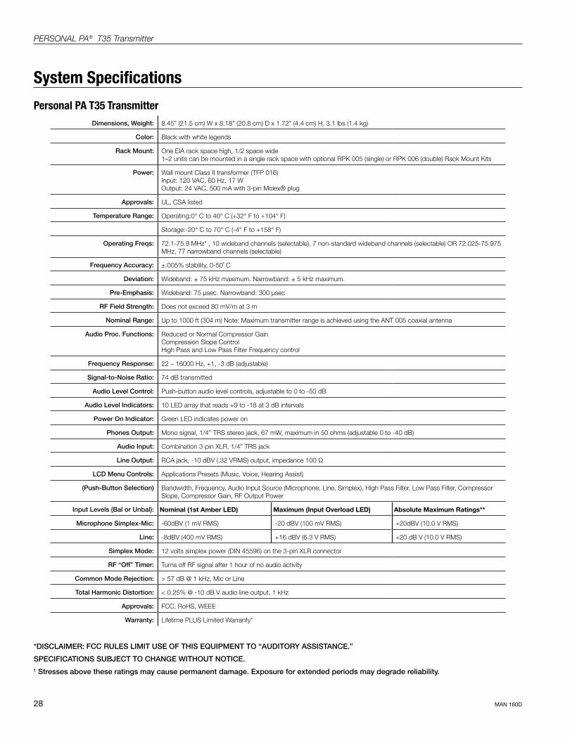
*DISCLAIMER: FCC RULES LIMIT USE OF THIS EQUIPMENT TO “AUDITORY ASSISTANCE.”
SPECIFICATIONS SUBJECT TO CHANGE WITHOUT NOTICE.1 Stresses above these ratings may cause permanent damage. Exposure for extended periods may degrade reliability.
Dimensions, Weight: 8.45” (21.5 cm) W x 8.18” (20.8 cm) D x 1.72” (4.4 cm) H, 3.1 lbs (1.4 kg)
Color: Black with white legends
Rack Mount: One EIA rack space high, 1/2 space wide 1–2 units can be mounted in a single rack space with optional RPK 005 (single) or RPK 006 (double) Rack Mount Kits
Power: Wall mount Class II transformer (TFP 016) Input: 120 VAC, 60 Hz, 17 W Output: 24 VAC, 500 mA with 3-pin Molex® plug
Approvals: UL, CSA listed
Temperature Range: Operating:0° C to 40° C (+32° F to +104° F)
Storage:-20° C to 70° C (-4° F to +158° F)
Operating Freqs: 72.1-75.9 MHz* , 10 wideband channels (selectable), 7 non-standard wideband channels (selectable) OR 72.025-75.975 MHz, 77 narrowband channels (selectable)
Frequency Accuracy: ±.005% stability, 0-50˚ C
Deviation: Wideband: ± 75 kHz maximum. Narrowband: ± 5 kHz maximum.
Pre-Emphasis: Wideband: 75 µsec. Narrowband: 300 µsec
RF Field Strength: Does not exceed 80 mV/m at 3 m
Nominal Range: Up to 1000 ft (304 m) Note: Maximum transmitter range is achieved using the ANT 005 coaxial antenna
Audio Proc. Functions: Reduced or Normal Compressor Gain Compression Slope Control High Pass and Low Pass Filter Frequency control
Frequency Response: 22 – 16000 Hz, +1, -3 dB (adjustable)
Signal-to-Noise Ratio: 74 dB transmitted
Audio Level Control: Push-button audio level controls, adjustable to 0 to -50 dB
Audio Level Indicators: 10 LED array that reads +9 to -18 at 3 dB intervals
Power On Indicator: Green LED indicates power on
Phones Output: Mono signal, 1/4” TRS stereo jack, 67 mW, maximum in 50 ohms (adjustable 0 to -40 dB)
Audio Input: Combination 3-pin XLR, 1/4” TRS jack
Line Output: RCA jack, -10 dBV (.32 VRMS) output, impedance 100 Ω
LCD Menu Controls: Applications Presets (Music, Voice, Hearing Assist)
(Push-Button Selection) Bandwidth, Frequency, Audio Input Source (Microphone, Line, Simplex), High Pass Filter, Low Pass Filter, Compressor Slope, Compressor Gain, RF Output Power
Input Levels (Bal or Unbal): Nominal (1st Amber LED) Maximum (Input Overload LED) Absolute Maximum Ratings**
Microphone Simplex-Mic: -60dBV (1 mV RMS) -20 dBV (100 mV RMS) +20dBV (10.0 V RMS)
Line: -8dBV (400 mV RMS) +16 dBV (6.3 V RMS) +20 dB V (10.0 V RMS)
Simplex Mode: 12 volts simplex power (DIN 45596) on the 3-pin XLR connector
RF “Off” Timer: Turns off RF signal after 1 hour of no audio activity
Common Mode Rejection: > 57 dB @ 1 kHz, Mic or Line
Total Harmonic Distortion: < 0.25% @ -10 dB V audio line output, 1 kHz
Approvals: FCC, RoHS, WEEE
Warranty: Lifetime PLUS Limited Warranty*

29
PERSONAL PA® T35 Transmitter
MAN 160D
PPA Select™ Receiver (Model PPA R37)
Dimensions: 4.1” x 2.85” x 1.38” (104 x 72 x 35mm)
Weight: 4.6oz (130g) with batteries. 2.6oz (73g) without batteries
Color: Black
Battery Type: (2) AA Alkaline or 2 x AA NiMH
Battery Life: Two (2) AA non-rechargeable alkaline batteries (BAT 001), approx. 50 hrs
(2) AA rechargeable NiMH batteries (BAT 026), 1500 mAh, approx. 32 hrs
Current Consumption: 52mA nominal
Temperature Range: – 0 to 50C
Channels 17, accessed via seek button in battery compartment
Operating Freq.: 72.1, 72.2, 72.3, 72.4, 72.5, 72.6, 72.7, 72.8, 72.9, 74.7, 75.3, 75.4, 75.5, 75.6, 75.7, 75.8, 75.9 MHz*
Intermediate Freq.: 75 kHz
FM Deviation: 75 kHz
De-Emphasis: 75 µS
LED Indicator: Power: Green; Low Battery: Flashes Green
AFC Range: ± 120 kHz
Sensitivity: 2 µV at 12 dB Sinad with squelch defeated
Input Overload: 100 mV
Frequency Response: 200 – 15 kHz
Modulation: FM, +/- 75 kHz peak deviation
Signal-to-Noise Ratio: 65 dB min @ 100 uV
Receive Antenna: Integral with earphone/headphone cord
Audio Output: 35 mW max, peak into 16 ohms
Output Connector: 3.5 mm stereo/mono phone jack
Earphone: Earbud-type with foam cushion, 3.5 mm plug, 32 Ω
Auto Shut-off Enters sleep mode after approx 6 mins of no RF signal
Approvals: FCC, Industry Canada, RoHS, WEEE
Warranty: Lifetime PLUS Limited Warranty. 90 days on cords, earphones, headphones, batteries and other accessories
System Specifications
*DISCLAIMER: FCC RULES LIMIT USE OF THIS EQUIPMENT TO “AUDITORY ASSISTANCE.”
NOTE: SPECIFICATIONS SUBJECT TO CHANGE WITHOUT NOTICE
This device complies to “RSS-Gen Issue 2 June 2007” for Industrie Canada and FCC part 15.105(b) for the United States. Operation is subject to the following two conditions: (1) this device may not cause interference, and (2) this device must accept any interference, including interference that may cause undesired operation of the device. This device complies with ICES-003 class B. Test data is available from the manufacturer on request.
30
PERSONAL PA® T35 Transmitter
MAN 160D
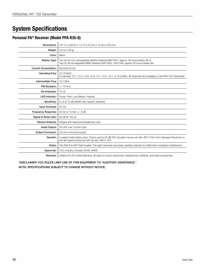
Personal PA® Receiver (Model PPA R35-8)
Dimensions: 4.5” H x 2.85 W x 1.2” D (115 mm x 72 mm x 30 mm)
Weight: 4.6 oz (130 g)
Color: Black
Battery Type: Two (2) AA non-rechargeable alkaline batteries (BAT 001), approx. 50 hours battery life or Two (2) AA rechargeable NiMH batteries (BAT 026), 1400 mAh, approx 32 hours battery life
Current Consumption: Nominal 40 mA
Operating Freq: 72-76 MHz*: 8 channels: 72.1, 72.3, 72.6, 72.8, 74.7, 75.4, 75.7, or 75.9 MHz. All Channels Not Available on the PPA T20 Transmitter
Intermediate Freq: 10.7 MHz
FM Deviation: +/- 75 kHz
De-emphasis: 75 uS
LED Indicator: Power: Red. Low Battery: Flashes
Sensitivity: 2 uV at 12 dB SINAD with squelch defeated
Input Overload: 20 mV
Frequency Response: 40 Hz to 15 kHz +/- 3 dB
Signal to Noise ratio: 60 dB at 100 uV
Receive Antenna: Integral with earphone/headphone cord
Audio Output: 35 mW, max 16 ohm load
Output Connector: 3.5 mm mono phone jack
Squelch: Located inside battery door. Factory set for 25 dB S/N. Squelch may be set with JFD-7104-5 from Sprague Goodman or any flat tipped tuning tool with tip size .095 X .016
Notes: The R35-8 is NOT field tunable. The eight channels have been carefully selected to inhibit inter-modulation interference.
Approvals: FCC, Industry Canada, RoHS, WEEE
Warranty: Lifetime PLUS Limited Warranty. 90 days on cords, earphones, headphones, batteries, and other accessories
*DISCLAIMER: FCC RULES LIMIT USE OF THIS EQUIPMENT TO “AUDITORY ASSISTANCE.”
NOTE: SPECIFICATIONS SUBJECT TO CHANGE WITHOUT NOTICE.
System Specifications

31
PERSONAL PA® T35 Transmitter
MAN 160D

PERSONAL PA® T35 Transmitter
MAN 160D ©2012 Williams Sound, LLC • All Rights ReservedPrinted in the USA
10300 Valley View Rd • Eden Prairie, MN 55344800-328-6190 / 952-943-2252 • FAX: 952-943-2174www.williamssound.com
Related Documents