Standard Pallet Jack (BPM5-2748) Please read and save these instructions. Read carefully before attempting to assemble, install, operate or maintain the product described. Protect yourself and others by observing all safety information. Failure to comply with instructions could result in personal injury and/or property damage! Retain instructions for future reference. Operating Instructions & Parts Manual Unpacking After receiving the pallet truck, visually inspect the frame components and hydraulic unit for damage. If damage is evident, notify delivering carrier immediately and file necessary claims. Assembly 1. Remove handle located just inside the top of the box. Unwrap the cardboard from the handle. Remove the four cap screws and grease paper located on the handle mounting pad. 2. Mount the steering handle from behind the pallet truck with the control lever pointed to the right. Feed the valve adjustment rod (See Figure 2) through the handle mounting pad between the chain roller and the reservoir. Using the previously removed cap screws, secure the handle to the mounting pad. 3. Valve adjustment: Place valve adjustment rod into the release lever. Adjust nut on rod until all trend functions of the unit operate correctly: Raise, Lower, and Neutral. 4. Verify that the oil plug (See Figure 2) is secured. 5. Test the pallet truck under load for proper operation. If hydraulic unit does not respond to movement of handle, move control lever into LOWER position and pump handle several times (air locks sometimes occur in many types of hydraulic systems during handling and transit). Description This hand hydraulic standard pallet jack is a manually operated industrial duty product designed to lift a maximum weight of 5,500 pounds by using a minimum number of handle strokes. Safety features include an overload bypass valve and a pressure compensated flow valve for controlled lowering. A hand-actuated control lever for selecting “raise,” “neutral,” and “lower” positions is standard. The steering wheels articulate for uniform axle loading on uneven floors. Failure to follow the proper operating instructions could result in injury and void the warranty. Dimensions Lowered Height of Forks 2- 7 /8” Overall Width Across Forks 27” Fork Length 48” Fork Width 7” Overall Length 62” Weight xxx 275 lbs. Raised Height 7- 3 /4” Load Capacity 5,500 lbs. Specifications Up/Down Control ........................ Hand Actuated 3 Front Wheels per Fork ........... Entry Guide Wheel, Load Wheel, Exit Guide Wheel Steering Wheels .......................... Polyurethane-On-Steel w/Dust Covers Strokes to Raised Height .......... 10 Push Rods ...................................... Solid Steel Construction, Adjustable Length Forks ............................................... 7” Double Wrapped and Reinforced Steering Radius ........................... 180° Handle Return ............................. Automatic Return to Vertical Figure 1 Revised 12-01 %HDFRQ ,QGXVWULHV ,QF 2OG 7HVVRQ 5G 6W /RXLV 02 86$ 2IILFH )D[ EHDFRQWHFKQRORJ\FRP (0DLO VDOHV#EHDFRQWHFKQROJ\FRP

Welcome message from author
This document is posted to help you gain knowledge. Please leave a comment to let me know what you think about it! Share it to your friends and learn new things together.
Transcript

Standard Pallet Jack (BPM5-2748)
Please read and save these instructions. Read carefully before attempting to assemble, install, operate or maintain the productdescribed. Protect yourself and others by observing all safety information. Failure to comply with instructions could result inpersonal injury and/or property damage! Retain instructions for future reference.
Operating Instructions & Parts Manual
UnpackingAfter receiving the pallet truck,visually inspect the frame componentsand hydraulic unit for damage. Ifdamage is evident, notify deliveringcarrier immediately and file necessaryclaims.
Assembly1. Remove handle located just inside
the top of the box. Unwrap thecardboard from the handle.Remove the four cap screws andgrease paper located on the handlemounting pad.
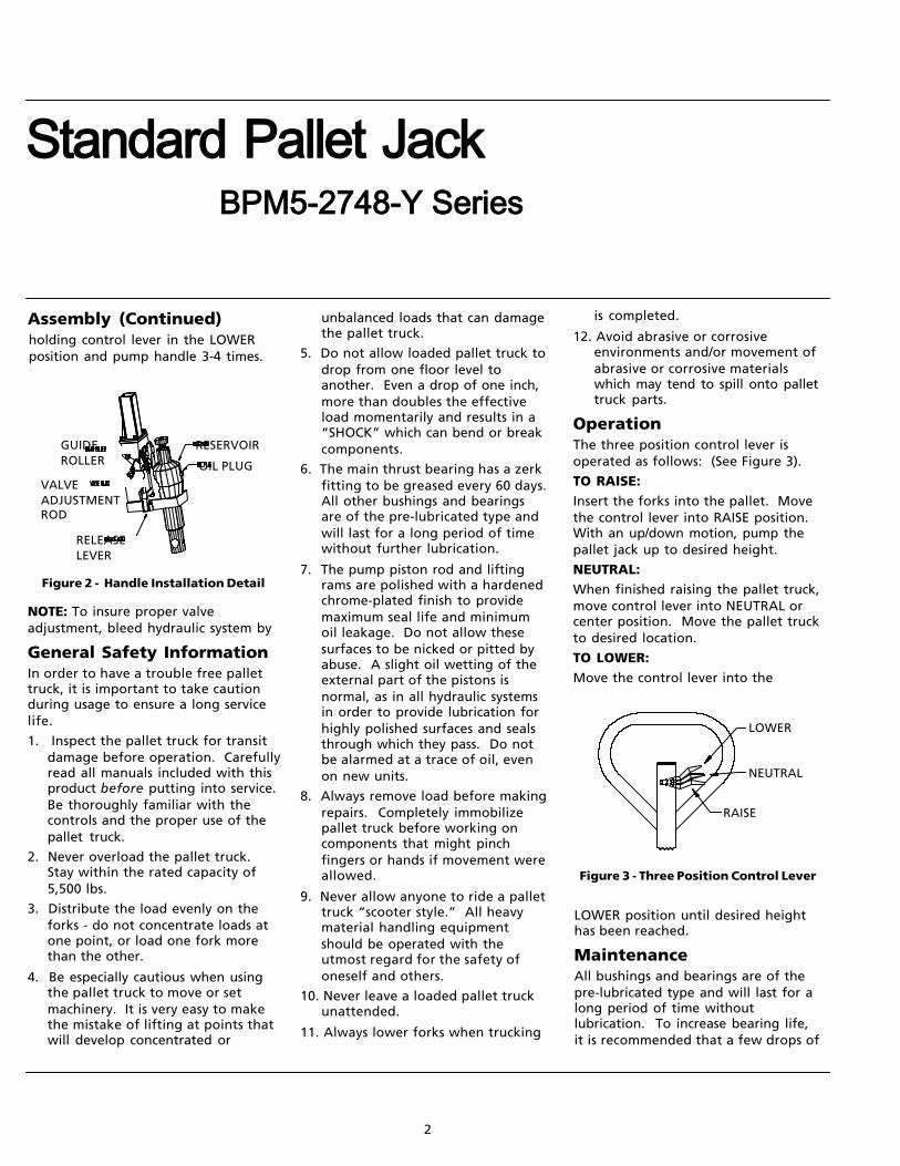
2. Mount the steering handle frombehind the pallet truck with thecontrol lever pointed to the right.Feed the valve adjustment rod (SeeFigure 2) through the handlemounting pad between the chainroller and the reservoir. Using thepreviously removed cap screws,secure the handle to the mountingpad.
3. Valve adjustment: Place valveadjustment rod into the releaselever. Adjust nut on rod until alltrend functions of the unit operatecorrectly: Raise, Lower, andNeutral.
4. Verify that the oil plug (See Figure2) is secured.
5. Test the pallet truck under loadfor proper operation. If hydraulicunit does not respond to movementof handle, move control lever intoLOWER position and pump handleseveral times (air locks sometimesoccur in many types of hydraulicsystems during handling andtransit).
DescriptionThis hand hydraulic standard pallet jack is a manually operated industrial duty product designed to lift a maximum weight of 5,500 pounds by using a minimum number of handle strokes.
Safety features include an overload bypass valve and a pressure compensated flowvalve for controlled lowering. A hand-actuated control lever for selecting “raise,”“neutral,” and “lower” positions is standard. The steering wheels articulate foruniform axle loading on uneven floors.
Failure to follow the proper operating instructions could result in injury and voidthe warranty.
DimensionsLowered Height
of Forks
2-7/8”
Overall WidthAcross Forks
27”
ForkLength
48”
ForkWidth
7”
OverallLength
62”
Weightxxx
275 lbs.
RaisedHeight7-3/4”
LoadCapacity5,500 lbs.
SpecificationsUp/Down Control ........................Hand Actuated
3 Front Wheels per Fork ........... Entry Guide Wheel, Load Wheel, Exit Guide Wheel
Steering Wheels .......................... Polyurethane-On-Steel w/Dust Covers
Strokes to Raised Height .......... 10
Push Rods ...................................... Solid Steel Construction, Adjustable Length
Forks ............................................... 7” Double Wrapped and Reinforced
Steering Radius ........................... 180°
Handle Return .............................Automatic Return to Vertical
Figure 1
Revised 12-01
Standard Pallet Jack
NOTE: To insure proper valveadjustment, bleed hydraulic system by
General Safety InformationIn order to have a trouble free pallettruck, it is important to take cautionduring usage to ensure a long servicelife.
1. Inspect the pallet truck for transitdamage before operation. Carefullyread all manuals included with thisproduct before putting into service.Be thoroughly familiar with thecontrols and the proper use of thepallet truck.
2. Never overload the pallet truck.Stay within the rated capacity of5,500 lbs.
3. Distribute the load evenly on theforks - do not concentrate loads atone point, or load one fork morethan the other.
4. Be especially cautious when usingthe pallet truck to move or setmachinery. It is very easy to makethe mistake of lifting at points thatwill develop concentrated or
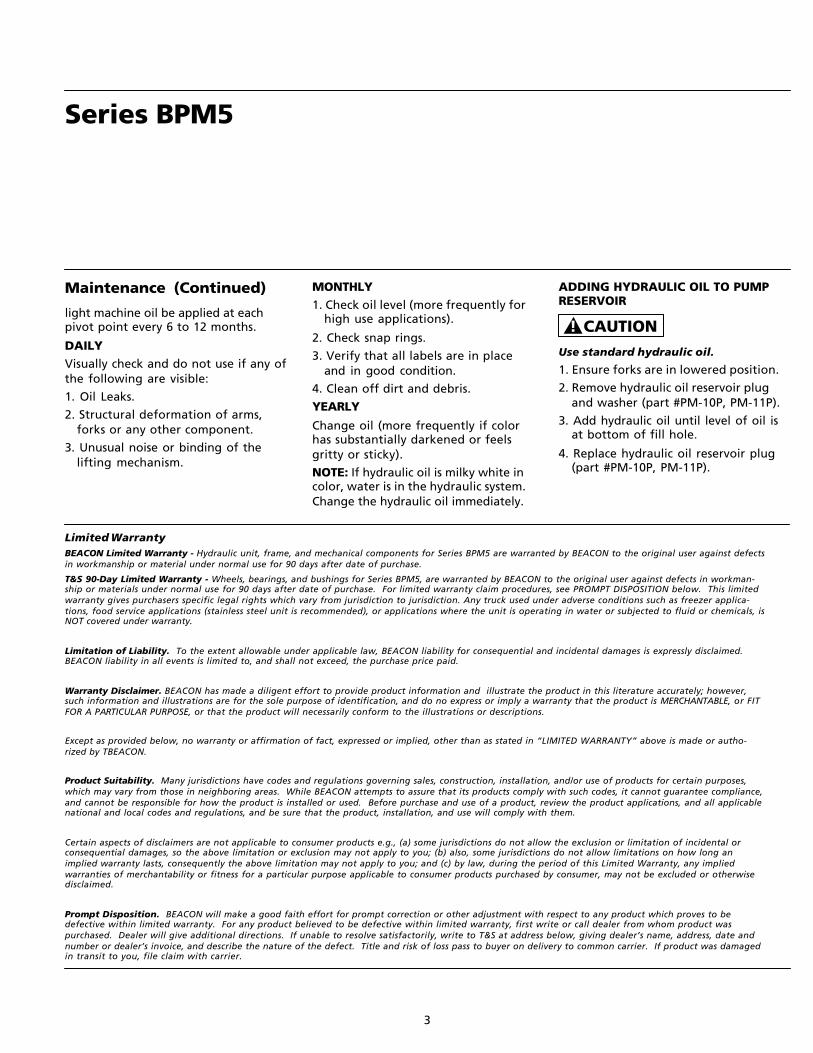
Figure 3 - Three Position Control Lever
unbalanced loads that can damagethe pallet truck.
5. Do not allow loaded pallet truck todrop from one floor level toanother. Even a drop of one inch,more than doubles the effectiveload momentarily and results in a“SHOCK” which can bend or breakcomponents.
6. The main thrust bearing has a zerkfitting to be greased every 60 days.All other bushings and bearingsare of the pre-lubricated type andwill last for a long period of timewithout further lubrication.
7. The pump piston rod and liftingrams are polished with a hardenedchrome-plated finish to providemaximum seal life and minimumoil leakage. Do not allow thesesurfaces to be nicked or pitted byabuse. A slight oil wetting of theexternal part of the pistons isnormal, as in all hydraulic systemsin order to provide lubrication forhighly polished surfaces and sealsthrough which they pass. Do notbe alarmed at a trace of oil, evenon new units.
8. Always remove load before makingrepairs. Completely immobilizepallet truck before working oncomponents that might pinchfingers or hands if movement wereallowed.
9. Never allow anyone to ride a pallettruck “scooter style.” All heavymaterial handling equipmentshould be operated with theutmost regard for the safety ofoneself and others.
10. Never leave a loaded pallet truckunattended.
11. Always lower forks when trucking
is completed.
12. Avoid abrasive or corrosiveenvironments and/or movement ofabrasive or corrosive materialswhich may tend to spill onto pallettruck parts.
OperationThe three position control lever isoperated as follows: (See Figure 3).
TO RAISE:Insert the forks into the pallet. Movethe control lever into RAISE position.With an up/down motion, pump thepallet jack up to desired height.
NEUTRAL:When finished raising the pallet truck,move control lever into NEUTRAL orcenter position. Move the pallet truckto desired location.
TO LOWER:Move the control lever into the
LOWER position until desired heighthas been reached.
MaintenanceAll bushings and bearings are of thepre-lubricated type and will last for along period of time withoutlubrication. To increase bearing life,it is recommended that a few drops of
Assembly (Continued)
Figure 2 - Handle Installation Detail
holding control lever in the LOWERposition and pump handle 3-4 times.
2
RELEASELEVER
OIL PLUG
RESERVOIRGUIDEROLLER
VALVEADJUSTMENTROD
LOWER
NEUTRAL
RAISE
BPM5-2748-Y Series
Series BPM5
Limited WarrantyBEACON Limited Warranty - Hydraulic unit, frame, and mechanical components for Series BPM5 are warranted by BEACON to the original user against defectsin workmanship or material under normal use for 90 days after date of purchase.
T&S 90-Day Limited Warranty - Wheels, bearings, and bushings for Series BPM5, are warranted by BEACON to the original user against defects in workman-ship or materials under normal use for 90 days after date of purchase. For limited warranty claim procedures, see PROMPT DISPOSITION below. This limitedwarranty gives purchasers specific legal rights which vary from jurisdiction to jurisdiction. Any truck used under adverse conditions such as freezer applica-tions, food service applications (stainless steel unit is recommended), or applications where the unit is operating in water or subjected to fluid or chemicals, isNOT covered under warranty.
Limitation of Liability. To the extent allowable under applicable law, BEACON liability for consequential and incidental damages is expressly disclaimed.BEACON liability in all events is limited to, and shall not exceed, the purchase price paid.
Warranty Disclaimer. BEACON has made a diligent effort to provide product information and illustrate the product in this literature accurately; however,such information and illustrations are for the sole purpose of identification, and do no express or imply a warranty that the product is MERCHANTABLE, or FITFOR A PARTICULAR PURPOSE, or that the product will necessarily conform to the illustrations or descriptions.
Except as provided below, no warranty or affirmation of fact, expressed or implied, other than as stated in “LIMITED WARRANTY” above is made or autho-rized by TBEACON.
Product Suitability. Many jurisdictions have codes and regulations governing sales, construction, installation, and/or use of products for certain purposes,which may vary from those in neighboring areas. While BEACON attempts to assure that its products comply with such codes, it cannot guarantee compliance,and cannot be responsible for how the product is installed or used. Before purchase and use of a product, review the product applications, and all applicablenational and local codes and regulations, and be sure that the product, installation, and use will comply with them.
Certain aspects of disclaimers are not applicable to consumer products e.g., (a) some jurisdictions do not allow the exclusion or limitation of incidental orconsequential damages, so the above limitation or exclusion may not apply to you; (b) also, some jurisdictions do not allow limitations on how long animplied warranty lasts, consequently the above limitation may not apply to you; and (c) by law, during the period of this Limited Warranty, any impliedwarranties of merchantability or fitness for a particular purpose applicable to consumer products purchased by consumer, may not be excluded or otherwisedisclaimed.
Prompt Disposition. BEACON will make a good faith effort for prompt correction or other adjustment with respect to any product which proves to bedefective within limited warranty. For any product believed to be defective within limited warranty, first write or call dealer from whom product waspurchased. Dealer will give additional directions. If unable to resolve satisfactorily, write to T&S at address below, giving dealer’s name, address, date andnumber or dealer’s invoice, and describe the nature of the defect. Title and risk of loss pass to buyer on delivery to common carrier. If product was damagedin transit to you, file claim with carrier.
light machine oil be applied at eachpivot point every 6 to 12 months.
DAILYVisually check and do not use if any ofthe following are visible:
1. Oil Leaks.
2. Structural deformation of arms,forks or any other component.
3. Unusual noise or binding of thelifting mechanism.
MONTHLY1. Check oil level (more frequently for
high use applications).
2. Check snap rings.
3. Verify that all labels are in placeand in good condition.
4. Clean off dirt and debris.
YEARLY
Change oil (more frequently if colorhas substantially darkened or feelsgritty or sticky).
NOTE: If hydraulic oil is milky white incolor, water is in the hydraulic system.Change the hydraulic oil immediately.
ADDING HYDRAULIC OIL TO PUMPRESERVOIR
Use standard hydraulic oil.
1. Ensure forks are in lowered position.
2. Remove hydraulic oil reservoir plugand washer (part #PM-10P, PM-11P).
3. Add hydraulic oil until level of oil isat bottom of fill hole.
4. Replace hydraulic oil reservoir plug(part #PM-10P, PM-11P).
Maintenance (Continued)
CAUTION!
3

Please provide following information:
-Model Number
-Serial Number
-Part description and number as shown in parts list
12
3
4
56
78
9
10
1112
13
14
15
4
1617
18
19
20
222324
25
2627
28B
293031
32 33
34 35
36
37
28A
38
39
40
Alternative
Design
45 4641 42 43 44
Pressure Relief System
Figure 4 - Hydraulic Pump, Wheel, and Axle Assembly
4
For Replacement Parts
ITEM NO.
1
2 3 4
5 6 7
8 910
111213
141516
171819
202122
232425
2627
28A
28B2930
313233
343536
373839
404142
434445
46AB
C
E
PART NO.
BPM-1P
BPM-2PBPM-3PBPM-4P
BPM-5PBPM-6PBPM-7P
BPM-8PBPM-9PBPM-10P
BPM-11PBPM-12PBPM-13P
BPM-14PBPM-15PBPM-16P
BPM-17PPBM-18PBPM-19P
BPM-20PBPM-21PBPM-22P
BPM-23PBPM-24PBPM-25P
BPM-26PBPM-27PBPM-28AP
BPM-28BPBPM-29PBPM-30P
BPM-31PBPM-32PBPM-33P
BPM-34PBPM-35PBPM-36P
BPM-37PBPM-38PBPM-39P
BPM-40PBPM-41PBPM-42P
BPM-43PBPM-44PBPM-45P
BPM-46PBPM-SKBPM-SWK
BPM-PMK
BPM-PCA
QTY.
2
214
221
111
111
111
111
111
111
111
111
111
111
112
111
111
111
1
1
DESCRIPTION
Hub Cap
Snap RingAxleBall Bearing
Steering WheelWasherRelease Valve
O-RingSpringNylon-Star Wahser
Oil Reservoir PlugSealSeal
WiperLift PistionBall
Cap RingPump Piston CapPump Piston
SpringWiperSeal
Spilt PinChain RollerPlug Bolt
O-RingSpringBall
BallO-RingBall Valve
PinPinRelease Lever
PinThrust BearingThrust Washer
Welded Hyd. ReservoirSnap RingSet Screw
Pump PistonAdjustment PlugSpring
PlungerCheck BallPlug Bolt
O-RingSeal KitSteering Wheel Kit (includes 1-6,34,35,36,38)
Pump, Mechanical Kit(includes 7,9,11,16-20,23-5,27,28A,28B,30-33)Pump, Complete Assembly (includes 7-33,37)
KIT NO.
B
BBB
BB
C,E
A,C,EC,E
A,C,E
C,EA,C,EA,C,E
A,C,EE
C,E
C,EC,EC,E
C,EA,C,EA,C,E
C,EC,EC,E
A,C,ED,EC,E
C,EA,C,E
C,E
C,EC,EC,E
BBB
EB
5
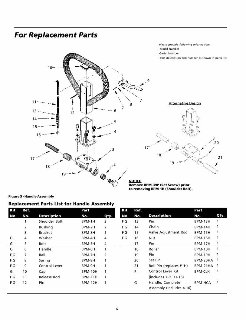
For Replacement PartsPlease provide following information:
-Model Number
-Serial Number
-Part description and number as shown in parts list
6
12
3
4
5
67
8
10
11
1213
14
15
16
17
18
7
19
9
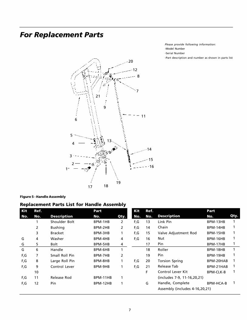
Replacement Parts List for Handle Assembly
Figure 5 - Handle Assembly
Ref.
No.13
14
15
16
17
18
19
20
21
F
G
Description
Pin
Chain
Valve Adjustment Rod
Nut
Pin
Roller
Pin
Set Pin
Roll Pin (replaces #1H)
Control Lever Kit
(includes 7-9, 11-16)
Handle, Complete
Assembly (includes 4-16)
Part
No.BPM-13H
BPM-14H
BPM-15H
BPM-16H
BPM-17H
BPM-18H
BPM-19H
BPM-20HA
BPM-21HA
BPM-CLK
BPM-HCA
Qty.
1
1
1
1
1
1
1
1
1
1
1
Kit
No.F,G
F,G
F,G
F,G
DescriptionShoulder Bolt
Bushing
Bracket
Washer
Bolt
Handle
Ball
Spring
Control Lever
Cap
Release Rod
Pin
Part
No.BPM-1H
BPM-2H
BPM-3H
BPM-4H
BPM-5H
BPM-6H
BPM-7H
BPM-8H
BPM-9H
BPM-10H
BPM-11H
BPM-12H
Qty.2
2
1
4
4
1
2
1
1
1
1
1
Kit
No.
G
G
G
F,G
F,G
F,G
G
F,G
F,G
Ref.
No.1
2
3
4
5
6
7
8
9
10
11
12
Alternative Design
NOTICERemove BPM-39P (Set Screw) priorto removing BPM-1H (Shoulder Bolt).
19
18
320
21
17
For Replacement PartsPlease provide following information:
-Model Number
-Serial Number
-Part description and number as shown in parts list
Replacement Parts List for Handle Assembly
Figure 5 - Handle Assembly
Ref.No.13
14
15
16
17
18
19
20
21
F
G
Description
Link Pin
Chain
Valve Adjustment Rod
Nut
Pin
Roller
Pin
Torsion Spring
Release Tab
Control Lever Kit
(includes 7-9, 11-16,20,21)
Handle, Complete
Assembly (includes 4-16,20,21)
PartNo.BPM-13HB
BPM-14HB
BPM-15HB
BPM-16HB
BPM-17HB
BPM-18HB
BPM-19HB
BPM-20HAB
BPM-21HAB
BPM-CLK-B
BPM-HCA-B
Qty.
1
1
1
1
1
1
1
1
1
1
1
KitNo.F,G
F,G
F,G
F,G
F,G
F,G
DescriptionShoulder Bolt
Bushing
Bracket
Washer
Bolt
Handle
Small Roll Pin
Large Roll Pin
Control Lever
Release Rod
Pin
PartNo.BPM-1HB
BPM-2HB
BPM-3HB
BPM-4HB
BPM-5HB
BPM-6HB
BPM-7HB
BPM-8HB
BPM-9HB
BPM-11HB
BPM-12HB
Qty.2
2
1
4
4
1
2
1
1
1
1
KitNo.
G
G
G
F,G
F,G
F,G
F,G
F,G
Ref.No.1
2
3
4
5
6
7
8
9
10
11
12
20
8
12
7
9
4
5
6
21
12
11
13
14
15
16
17 1819
3
7

For Replacement PartsPlease provide following information:
-Model Number
-Serial Number
-Part description and number as shown in parts list
8
1
23
45
678
910
4
2
8
11A
12
14
15
1613
17
181920
21
22
24
25
26
12
12
122112
15
1211B
Replacement Parts List for Frame Assembly
Figure 6 - Frame Assembly
Ref.
No.14
15
16
17
18
19
20
21
22
23
24
25
26
H
DescriptionPin
Bushing
Exit Roller
Push Rod
Lock Nut
Eye bolt
Pin
Shoulder Bolt
Thrust Plate
Torsion Tube
Pin
Split Pin
Chassis
Load Roller Kit
(includes 1-10, 12-16)
Part
No.BPM-14F
BPM-15F
BPM-16F
BPM-17F
BPM-18F
BPM-19F
BPM-20F
BPM-21F
BPM-22F
BPM-23F
BPM-24F
BPM-25F
BPM-26F
BPM-LRK
Qty.2
4
2
2
2
2
2
2
1
1
2
4
1
2
Kit
No.H
H
H
Ref.
No. 1
2
3
4
5
6
7
8
9
10
11A
11B
12
13
DescriptionBolt
Washer
Roller Shaft
Bearing
Load Roller
Lock Washer
Nut
Pin
Bolt
Entry Roller
Lever Arms (Left)
Lever Arms (Right)
Bushing
Pin
Part
No.BPM-1F
BPM-2F
BPM-3F
BPM-4F
BPM-5F
BPM-6F
BPM-7F
BPM-8F
BPM-9F
BPM-10F
BPM-11AF
BPM-11BF
BPM-12F
BPM-13F
Qty.2
4
2
4
2
2
2
4
2
2
2
2
10
6
Kit
No.H
H
H
H
H
H
H
H
H
H
H
H
23
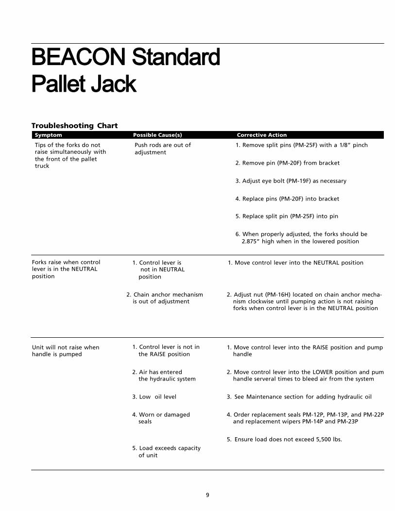
Tips of the forks do notraise simultaneously withthe front of the pallettruck
1. Remove split pins (PM-25F) with a 1/8” pinch
2. Remove pin (PM-20F) from bracket
3. Adjust eye bolt (PM-19F) as necessary
4. Replace pins (PM-20F) into bracket
5. Replace split pin (PM-25F) into pin
6. When properly adjusted, the forks should be2.875” high when in the lowered position
Push rods are out ofadjustment
Troubleshooting ChartSymptom Corrective ActionPossible Cause(s)
9
Forks raise when controllever is in the NEUTRALposition
1. Control lever isnot in NEUTRAL
position
1. Move control lever into the NEUTRAL position
2. Adjust nut (PM-16H) located on chain anchor mecha-nism clockwise until pumping action is not raisingforks when control lever is in the NEUTRAL position
2. Chain anchor mechanismis out of adjustment
Unit will not raise whenhandle is pumped
1. Control lever is not inthe RAISE position
2. Air has enteredthe hydraulic system
3. Low oil level
4. Worn or damagedseals
5. Load exceeds capacityof unit
1. Move control lever into the RAISE position and pumphandle
2. Move control lever into the LOWER position and pumhandle serveral times to bleed air from the system
3. See Maintenance section for adding hydraulic oil
4. Order replacement seals PM-12P, PM-13P, and PM-22Pand replacement wipers PM-14P and PM-23P
5. Ensure load does not exceed 5,500 lbs.
BEACON Standard Pallet Jack
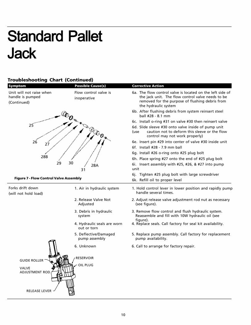
RELEASE LEVER
OIL PLUG
RESERVOIRGUIDE ROLLER
VALVEADJUSTMENT ROD
10
Troubleshooting Chart (Continued)Symptom Corrective ActionPossible Cause(s)
Unit will not raise whenhandle is pumped
(Continued)
6a. The flow control valve is located on the left side ofthe jack unit. The flow control valve needs to beremoved for the purpose of flushing debris fromthe hydraulic system
6b. After flushing debris from system reinsert steelball #28 - 8.1 mm
6c. Install o-ring #31 on valve #30 then reinsert valve
6d. Slide sleeve #30 onto valve inside of pump unit(use caution not to deform this sleeve or the flow
control may not work properly)
6e. Insert pin #29 into center of valve #30 inside unit
6f. Install #28 - 7.9 mm ball
6g. Install #26 o-ring onto #25 plug bolt
6h. Place spring #27 onto the end of #25 plug bolt
6i. Insert assembly with #25, #26, & #27 into pumpunit
6j. Tighten #25 plug bolt with large screwdriver
6k. Refill oil to proper level
Flow control valve is
inoperative
25
26 27
28B
29 30
3128A
Figure 7 - Flow Control Valve Assembly
Forks drift down
(will not hold load)1. Air in hydraulic system 1. Hold control lever in lower position and rapidly pump
handle several times.
2. Adjust release valve adjustment rod nut as necessary(see figure).
2. Release Valve NotAdjusted
3. Remove flow control and flush hydraulic system.Reassemble and fill with 10W hydraulic oil (seefigure).
3. Debris in hydraulicsystem
4. Replace seals. Call factory for seal kit availability.4. Hydraulic seals are wornout or torn
5. Replace pump assembly. Call factory for replacementpump availability.
5. Deflective/Damagedpump assembly
6. Call to arrange for factory repair.6. Unknown
Standard Pallet Jack

Notes
11
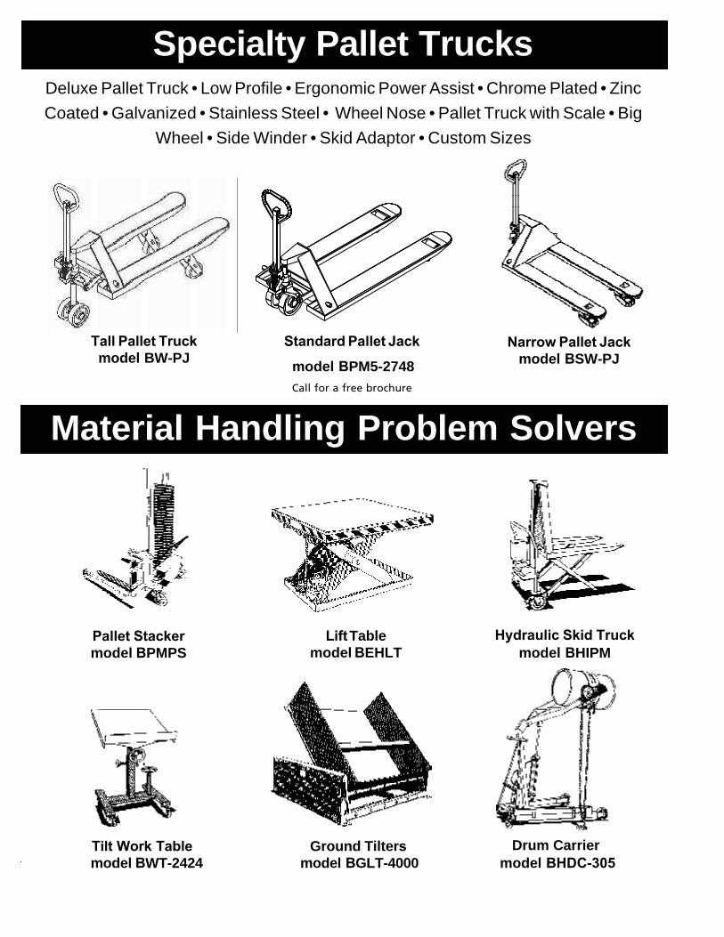
Specialty Pallet Trucks
Tall Pallet Truckmodel BW-PJ
Narrow Pallet Jack model BSW-PJ
Deluxe Pallet Truck • Low Profile • Ergonomic Power Assist • Chrome Plated • ZincCoated • Galvanized • Stainless Steel • Wheel Nose • Pallet Truck with Scale • Big
Wheel • Side Winder • Skid Adaptor • Custom Sizes
Standard Pallet Jack
model BPM5-2748 Call for a free brochure
Material Handling Problem Solvers
Pallet Stacker model BPMPS
Lift Table model BEHLT
Hydraulic Skid Truckmodel BHIPM
Tilt Work Tablemodel BWT-2424
Ground Tiltersmodel BGLT-4000
Drum Carriermodel BHDC-305
Related Documents