Personal Communication Systems (PCS) VICTOR 0. K. LI, FELLOW, IEEE, AND XIAOXM QIU, STUDENT MEMBER, IEEE Personal communication systems (PCS) represent a rapidly growing and increasingly important segment of the telecommu- nication industry. The goal of PCS is to provide truly personal, cost-eficient communication services to users through portable handrets. In this paper, we present a survey on the research and development in PCS, emphasizing several important aspects such as the PCS concept, service requirements,system architecture, op- eration, and management. Some ongoing field trials are described as well. We focus on the wireless and the mobility-related features of PCS, discuss their impact on the system design and performance, and provide an overview of different technology choices. A. What is PCS? PCS promises to provide a wide range of location- and equipment-independent services to a large number of users. According to the definition given by the Us Federal Communications Commission (FCC) in its Notice of ~ ~ ~ ~ j r , PCS is the system by which every can exchange with anyone' at anytime' in any Place, through any type of device, using a single personal telecommunication number (PTN) [38]. The main features of PCS can be summed up as follows I. INTRODUCTION The past several years have been exciting for wireless communications. The explosion of technological alterna- tives, the operation of the first generation systems, and the commercialization of the second generation systems have stimulated much public interest and a mass market for wireless communications. As the public has become more aware of their benefits, demand has begun to ap- pear for even more advanced forms of services-personal communication services. These services provide significant advances over those currently available. The most important advancement is that the person-to-person communication concept replaces the station-to-station concept. The ultimate goal is to provide the timely exchange of various kinds of information (voice/data/video/image) with anyone, any- where, at anytime, at low cost through portable handsets. This ambition has spawned intense research and develop- ment efforts toward a new generation of communication systems-personal communication systems (PCS). The aim of this paper is to report on current PCS research and development. After a brief description of the PCS concept and its general requirements, we review its history. This will familiarize the reader with PCS. Then the progress made to meet these requirements and the corresponding technical choices are addressed. 1311, [361, [471, [511, [691, [731, [1441, [ W , [1521. 1) Multiple Environments: PCS can provide ubiquitous access to services, no matter whether the user is at home, in the office, in the car, etc. To achieve this objective, PCS should be able to integrate the current public switched telephone network (PSTN), integrated services digital network (ISDN), the cord- less system, the terrestrial mobile system, the satellite system, and the wireless PBX, to provide a suffi- ciently standardized environment such that ubiquitous communication is possible. From the user's point of view, PCS is an integrated service system even though many serving networks (operated by different service providers) may be involved. The change of serving networks should be transparent to the user, i.e., he should be able to maintain his connection as he roams from one serving network to another. 2) Multimedia Services with High Quality: PCS promises to provide a wide range of services to users, including high quality voice, variable rate data, full motion video, high resolution image, etc. The counterparts of those services available in ISDN will also be available in the wireless environment with the same quality [ l l l ] , [161]. 3) Multiple User Types: PCS will provide services to various users with different requirements, e.g., differ- ent service delay, different error performance, etc., by defining interfaces for negotiation between the user and the system. Manuscript received February IO, 1994, 1995; revised May 16, 1995. This work was supported in part by the National Science Foundation under Grant Number NCR-9016348. The authors are with the Communication Sciences Institute, Department of Electrical Engineering-Systems, University of Southem Califomia, Los Angeles, CA 90089-2565 USA. 4) Global Roaming Capability: PCS will have the ca- pability to support global roaming. The user is no GEE Log Number 9413473. longer tied to one point or one network, but can roam 0018-9219/95%04.00 0 1995 IEEE 1210 PROCEEDINGS OF THE IEEE, VOL. 83, NO. 9, SEPTEMBER 1995

Welcome message from author
This document is posted to help you gain knowledge. Please leave a comment to let me know what you think about it! Share it to your friends and learn new things together.
Transcript

Personal Communication Systems (PCS) VICTOR 0. K. LI, FELLOW, IEEE, AND XIAOXM QIU, STUDENT MEMBER, IEEE
Personal communication systems (PCS) represent a rapidly growing and increasingly important segment of the telecommu- nication industry. The goal of PCS is to provide truly personal, cost-eficient communication services to users through portable handrets. In this paper, we present a survey on the research and development in PCS, emphasizing several important aspects such as the PCS concept, service requirements, system architecture, op- eration, and management. Some ongoing field trials are described as well. We focus on the wireless and the mobility-related features of PCS, discuss their impact on the system design and performance, and provide an overview of different technology choices.
A. What is PCS? PCS promises to provide a wide range of location-
and equipment-independent services to a large number of users. According to the definition given by the Us Federal Communications Commission (FCC) in its Notice of ~ ~ ~ ~ j r , PCS is the system by which every can exchange with anyone' at anytime' in any Place, through any type of device, using a single personal telecommunication number (PTN) [38].
The main features of PCS can be summed up as follows
I. INTRODUCTION
The past several years have been exciting for wireless communications. The explosion of technological alterna- tives, the operation of the first generation systems, and the commercialization of the second generation systems have stimulated much public interest and a mass market for wireless communications. As the public has become more aware of their benefits, demand has begun to ap- pear for even more advanced forms of services-personal communication services. These services provide significant advances over those currently available. The most important advancement is that the person-to-person communication concept replaces the station-to-station concept. The ultimate goal is to provide the timely exchange of various kinds of information (voice/data/video/image) with anyone, any- where, at anytime, at low cost through portable handsets. This ambition has spawned intense research and develop- ment efforts toward a new generation of communication systems-personal communication systems (PCS).
The aim of this paper is to report on current PCS research and development. After a brief description of the PCS concept and its general requirements, we review its history. This will familiarize the reader with PCS. Then the progress made to meet these requirements and the corresponding technical choices are addressed.
1311, [361, [471, [511, [691, [731, [1441, [ W , [1521.
1) Multiple Environments: PCS can provide ubiquitous access to services, no matter whether the user is at home, in the office, in the car, etc. To achieve this objective, PCS should be able to integrate the current public switched telephone network (PSTN), integrated services digital network (ISDN), the cord- less system, the terrestrial mobile system, the satellite system, and the wireless PBX, to provide a suffi- ciently standardized environment such that ubiquitous communication is possible.
From the user's point of view, PCS is an integrated service system even though many serving networks (operated by different service providers) may be involved. The change of serving networks should be transparent to the user, i.e., he should be able to maintain his connection as he roams from one serving network to another.
2 ) Multimedia Services with High Quality: PCS promises to provide a wide range of services to users, including high quality voice, variable rate data, full motion video, high resolution image, etc. The counterparts of those services available in ISDN will also be available in the wireless environment with the same quality [ l l l ] , [161].
3) Multiple User Types: PCS will provide services to various users with different requirements, e.g., differ- ent service delay, different error performance, etc., by defining interfaces for negotiation between the user and the system.
Manuscript received February IO, 1994, 1995; revised May 16, 1995. This work was supported in part by the National Science Foundation under Grant Number NCR-9016348.
The authors are with the Communication Sciences Institute, Department of Electrical Engineering-Systems, University of Southem Califomia, Los Angeles, CA 90089-2565 USA.
4) Global Roaming Capability: PCS will have the ca- pability to support global roaming. The user is no
GEE Log Number 9413473. longer tied to one point or one network, but can roam
0018-9219/95%04.00 0 1995 IEEE
1210 PROCEEDINGS OF THE IEEE, VOL. 83, NO. 9, SEPTEMBER 1995
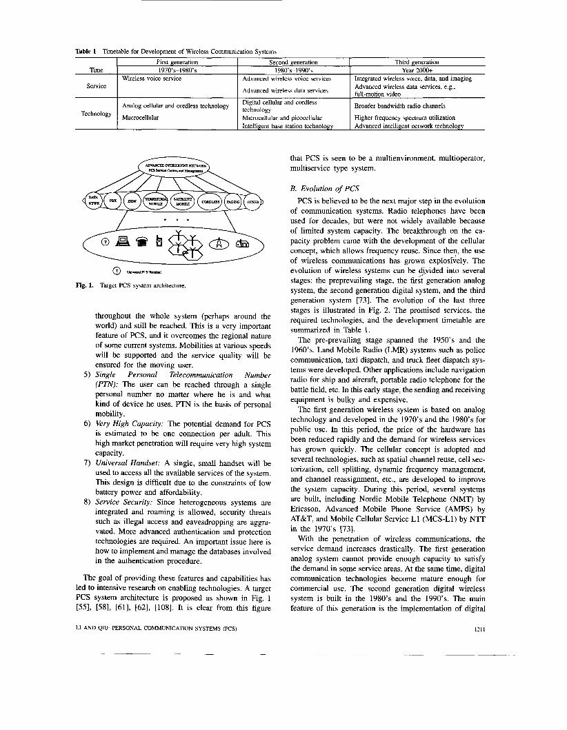
Table 1 Timetable for Development of Wireless Communication Systems
Time
Service
First generation 1970’~-1980’s
Wireless voice service
Analog cellular and cordless technology
Macrocellular
Second generation 1980’~-1990’~
Advanced wireless voice services Advanced wireless data services, e.g., full-motion video
Broader bandwidth radio channels
Advanced wireless data services
Digital cellular and cordless technology
Third generation Year 2000+
Integrated wireless voice, data, and imaging
Microcellular and picocellular Intelligent base station technology
(r) W f f E I C r m h d
Fig. 1. Target PCS system architecture.
Higher frequency spectrum utilization Advanced intelligent network technology
throughout the whole system (perhaps around the world) and still be reached. This is a very important feature of PCS, and it overcomes the regional nature of some current systems. Mobilities at various speeds will be supported and the service quality will be ensured for the moving user.
5 ) Single Personal Telecommunication Number (PTN): The user can be reached through a single personal number no matter where he is and what kind of device he uses. PTN is the basis of personal mobility.
6) Very High Capaci ty: The potential demand for PCS is estimated to be one connection per adult. This high market penetration will require very high system capacity.
7) Universal Handset: A single, small handset will be used to access all the available services of the system. This design is difficult due to the constraints of low battery power and affordability.
8) Service Security: Since heterogeneous systems are integrated and roaming is allowed, security threats such as illegal access and eavesdropping are aggra- vated. More advanced authentication and protection technologies are required. An important issue here is how to implement and manage the databases involved in the authentication procedure.
The goal of providing these features and capabilities has led to intensive research on enabling technologies. A target PCS system architecture is proposed as shown in Fig. 1 [55], [58], [61], [62], [108]. It is clear from this figure
that PCS is seen to be a multienvironment, multioperator, multiservice type system.
B. Evolution of PCS
PCS is believed to be the next major step in the evolution of communication systems. Radio telephones have been used for decades, but were not widely available because of limited system capacity. The breakthrough on the ca- pacity problem came with the development of the cellular concept, which allows frequency reuse. Since then, the use of wireless communications has grown exploslvely. The evolution of wireless systems can be dyided into several stages: the preprevailing stage, the first generation analog system, the second generation digital system, and the third generation system [73]. The evolution of the last three stages is illustrated in Fig. 2. The promised services, the required technologies, and the development timetable are summarized in Table 1.
The pre-prevailing stage spanned the 1950’s and the 1960’s. Land Mobile Radio (LMR) systems such as police communication, taxi dispatch, and truck fleet dispatch sys- tems were developed. Other applications include navigation radio for ship and aircraft, portable radio telephone for the battle field, etc. In this early stage, the sending and receiving equipment is bulky and expensive.
The first generation wireless system is based on analog technology and developed in the 1970’s and the 1980’s for public use. In this period, the price of the hardware has been reduced rapidly and the demand for wireless services has grown quickly. The cellular concept is adopted and several technologies, such as spatial channel reuse, cell sec- torization, cell splitting, dynamic frequency management, and channel reassignment, etc., are developed to improve the system capacity. During this period, several systems are built, including Nordic Mobile Telephone (NMT) by Ericsson, Advanced Mobile Phone Service (AMPS) by AT&T, and Mobile Cellular Service L1 (MCS-L1) by NTT in the 1970’s [73].
With the penetration of wireless communications, the service demand increases drastically. The first generation analog system cannot provide enough capacity to satisfy the demand in some service areas. At the same time, digital communication technologies become mature enough for commercial use. The second generation digital wireless system is built in the 1980’s and the 1990’s. The main feature of this generation is the implementation of digital
LI AND Qm PERSONAL COMMUNICATION SYSTEMS (KS) 121 1

PERSONAL
CATIONS
CORDLESS CORDLESS PHONE PHONE c
3 ENHANCED PAGING
PAGING
I I I .r 1990 1995 zoo0 YEAR
Fig. 2. Evolution of PCS.
technology. The system capacity is several times higher than the traditional analog system. More service features are introduced, the service quality is improved, and the service cost is significantly reduced. In this stage, the mobile communication system and the cordless communication system are developed separately to provide services to users with different mobility patterns and different requirements. The typical digital wireless communication systems include Global System for Mobile Communications (GSM) in Eu- rope, Digital AMPS in North America, Japanese Digital Cellular (JDC) in Japan, mainly for mobile service; and CT- 2 in Europe, mainly for cordless service. The comparison of some existing mobile and cordless telephone systems is given in [73].
With the development of the second generation wireless communication system, the demand for wireless commu- nications services has grown tremendously with growth rates of 20-50% per year in various parts of the world. With this astonishing growth, the existing capacity in some market areas is close to saturation. This stimulates the development of new technologies such as code division multiple access (CDMA) to utilize the available spectrum more efficiently. At the same time, the practice of mobile voice communications also stimulates the market in other personal communication services. Paging, which was used only by a small group of people, such as doctors, gained popularity very quickly starting in the early 1980's. Portable
computing and wireless data communication have become not only attractive but also feasible. Several standards are proposed for wireless data services. In Europe, a new technical committee, ETSI RES 10, has been established to specify the High Performance European Radio LAN (HIPER-LAN). Several mobile data networks are currently available to provide packet data services, including ARDIS by IBM and Motorola, MOBITEX by Ericsson and Swedish Telecom, Cellular Digital Packet Data (CDPD) by IBM et al., etc. [113]. With the development of technologies, the integration of both wired and wireless, voice and data services will be achieved in the coming years. Several experimental systems, such as the Personal Access Satellite Systems (PASS) of the Jet Propulsion Laboratory [68], [85], Universal Mobile Telecommunication System (UMTS) and the Future Public Land Mobile Telecommunication Systems (FPLMTS) are being proposed and tested in order to gain valuable user and operator experience.
Although most discussions on PCS have focused on the terrestrial system, we believe the satellite mobile system will also play a significant role. Satellite service comple- ments the existing terrestrial systems by providing coverage in geographical areas where the terrestrial component can- not physically or economically provide coverage, e.g., coverage of ships, aircraft, and users in rural areas. In ad- dition, it is crucial to support the global roaming feature of PCS [94]. The key problem in satellite system design is the
1212 PROCEEDINGS OF THE LEEE, VOL. 83, NO. 9, SEPTEMBER 1995
SEXVICECREAnON ENVIRONMENT
Fig. 3. Application of the intelligent network in PCS: Logical architecture.
efficient use of two critical satellite resources-bandwidth and power. The cellular concept is also introduced in the satellite system to increase the system capacity [85]. There are many satellite mobile systems operating currently, such as MARISAT, INMARSAT, Global Positioning System (GPS), Total Access Communications System (TACS), etc. [73]. The detailed descriptions and comparisons of these systems can be found in [73].
C. Contents of This Paper In the first part of this paper, we discuss the basic concept
and service requirements of PCS and review the history of its development. Then the work in network architec- ture design is described in Section 11. The corresponding operation and management issues, such as radio resource management, mobility management, and other miscella- neous issues, are addressed in Section 111. The related technologies are briefly reviewed and the major results
LI AND QIU: PERSONAL COMMUNICATION SYSTEMS (PCS)
are highlighted. Note that in this paper, we emphasize the required technologies associated with the wireless feature of PCS. We review PCS field trials in Section JV, and we conclude with Section V.
11. NETWORK ARCHITECTURE OF PCs Network architecture defines the functional elements of
the network, the interfaces between these elements, and the information flow between those interfaces. The ser- vices provided by PCS determine its network architecture. The promise of global and cost-efficient communications requires the integration of heterogeneous networks and compatibility with the existing systems. Preservation of what has been proven to work is a successful method to develop a new system [136]. Therefore, the PCS network design should not only consider the new features of PCS (global roaming, multimobility, multienvironment, personal telecommunication number, etc.), but also build on the
1213
Function Service Control Service Switching Service Data Service Resource
Service Management Switch-to-Comuuter
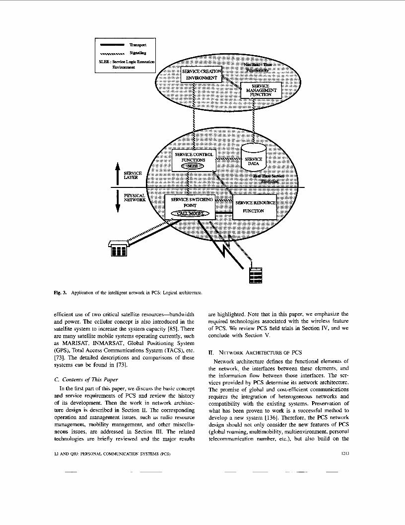
Enables creation of services independent of the underlying IN platform Service Creation Environment Service Logic Execution Environment
Description Responsible for execution of service Responsible for routing, measurements Responsible for intemal data services Responsible for speech prompts, speech recognition, connection bridging, digit recognition, human-machine interface Responsible for maintenance and modification of service data Allows end-users direct access to some IN capabilities
experience of the second generation systems such as GSM, DECT, JDC, D-AMPS, etc.
One important requirement of the PCS network architec- ture is that it should provide design flexibility (adaptable to various environments, various demands, etc.), service flexibility (amenable to additions of new services, etc.), and operational flexibility (simple system maintenance, etc.). To satisfy these requirements, an important development in PCS network architecture design is the introduction of the intelligent network (IN) concept. IN has powerful functions which are very well suited to providing the flexibility required in PCS. We list the basic IN functions as follows: Service Switching Function, Service Control Function, Service Data Function, Service Resource Func- tion, Service Management Function, Switch-to-Computer Application Interface, Service Logic Execution Environ- ment, and Service Creation Environment. These functions are described in detail in Table 2 and the relationships among them are illustrated in Fig. 3 [57]. The general idea of IN is to decouple the control sequences from the network resources and the user data and to separate the provided services from the underlying network platform, in order to provide flexible definition and rapid creation of new services [19], [%I, [61], [621, [107], [175]. IN will be the intelligent manager in PCS to support truly personal, location-independent communications. It is believed that PCS will be one of the major applications of IN and the crucial driver for it. The general concept of IN is described in [61]. The application of IN in PCS is discussed in [%I, [621.
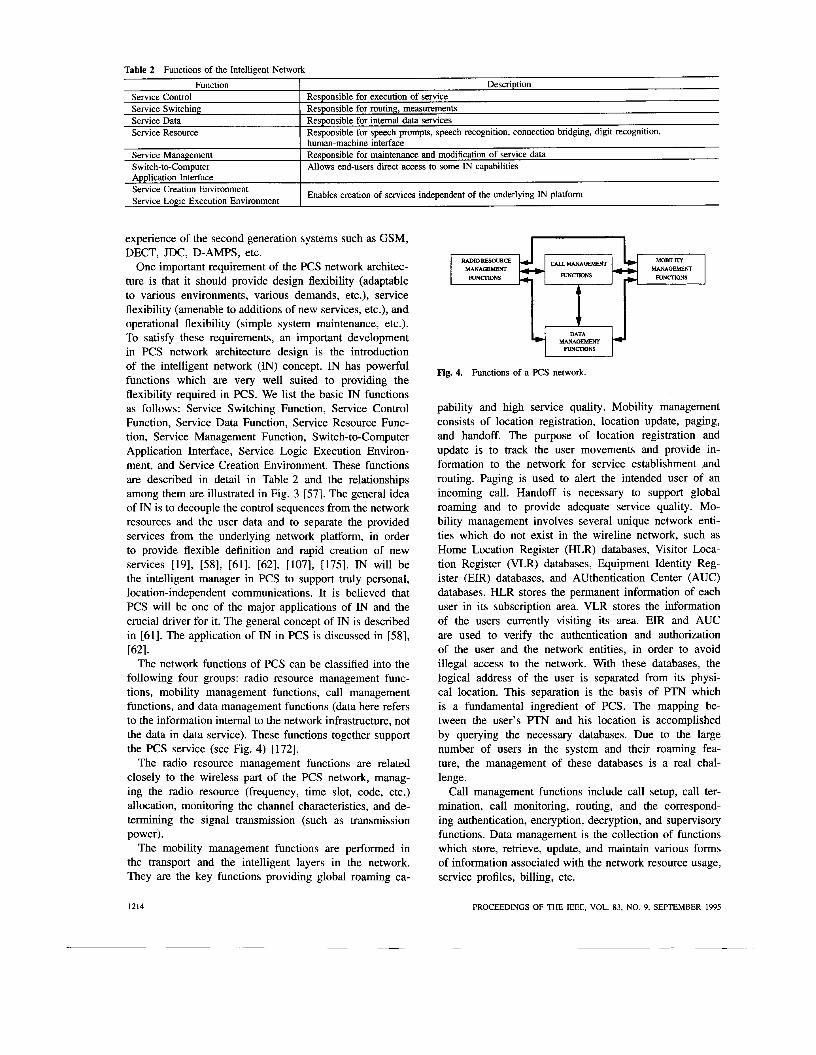
The network functions of PCS can be classified into the following four groups: radio resource management func- tions, mobility management functions, call management functions, and data management functions (data here refers to the information intemal to the network infrastructure, not the data in data service). These functions together support the PCS service (see Fig. 4) [172].
The radio resource management functions are related closely to the wireless part of the PCS network, manag- ing the radio resource (frequency, time slot, code, etc.) allocation, monitoring the channel characteristics, and de- termining the signal transmission (such as transmission power).
The mobility management functions are performed in the transport and the intelligent layers in the network. They are the key functions providing global roaming ca-
RALNoRESOURa MANAGEMENT
FUNCnONS c) +
MOBUrrY MANAGEMENT
CALLMANAGEMENI
FUNCIMNS - + FUNCTIONS
Fig. 4. Functions of a PCS network.
DATA
pability and high service quality. Mobility management consists of location registration, location update, paging, and handoff. The purpose of location registration and update is to track the user movements and provide in- formation to the network for service establishment and routing. Paging is used to alert the intended user of an incoming call. Handoff is necessary to support global roaming and to provide adequate service quality. Mo- bility management involves several unique network enti- ties which do not exist in the wireline network, such as Home Location Register (HLR) databases, Visitor Loca- tion Register (VLR) databases, Equipment Identity Reg- ister (EIR) databases, and Authentication Center (AUC) databases. HLR stores the permanent information of each user in its subscription area. VLR stores the information of the users currently visiting its area. EIR and AUC are used to verify the authentication and authorization of the user and the network entities, in order to avoid illegal access to the network. With these databases, the logical address of the user is separated from its physi- cal location. This separation is the basis of PTN which is a fundamental ingredient of PCS. The mapping be- tween the user’s PTN and his location is accomplished by querying the necessary databases. Due to the large number of users in the system and their roaming fea- ture, the management of these databases is a real chal- lenge.
Call management functions include call setup, call ter- mination, call monitoring, routing, and the correspond- ing authentication, encryption, decryption, and supervisory functions. Data management is the collection of functions which store, retrieve, update, and maintain various forms of information associated with the network resource usage, service profiles, billing, etc.
W A - FUNCIMNS
1214
*
PROCEEDINGS OF THE IEEE, VOL. 83, NO. 9, SEPTEMBER 1995
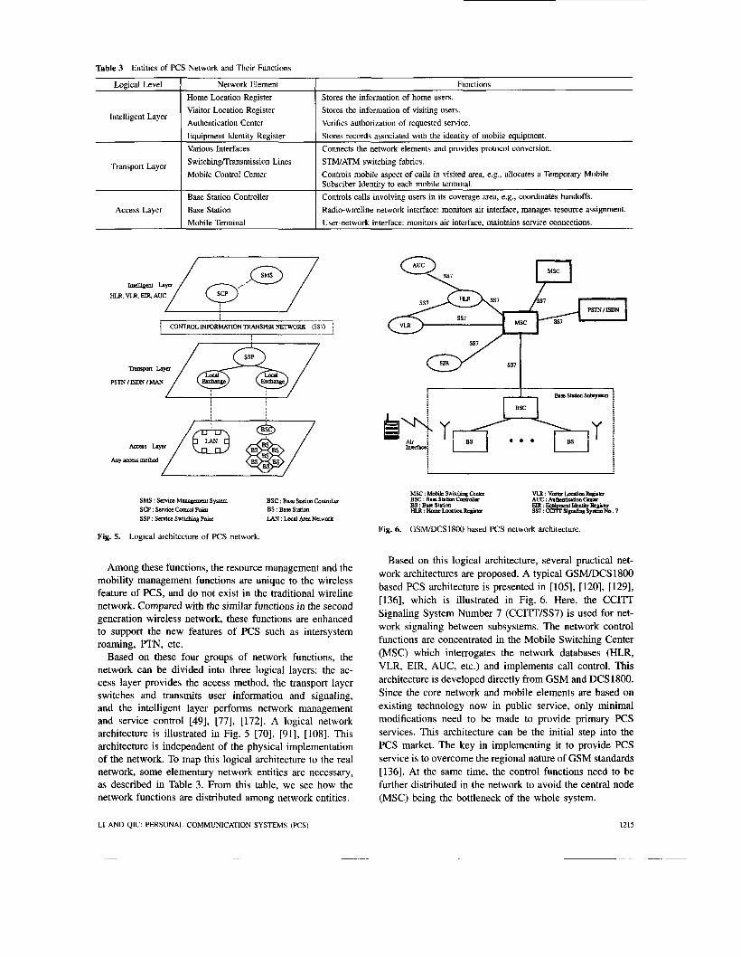
Table 3 Entities of PCS Network and Their Functions
Logical Level
Intelligent Layer
Transport Layer
Access Layer
Network Element Functions Home Location Register Visitor Location Register Authentication Center Equipment Identity Register Various Interfaces SwitchinglTransmission Lines STM/ATM switching fabrics. Mobile Control Center
Base Station Controller Base Station Mobile Terminal
Stores the information of home users. Stores the information of visiting users. Verifies authorization of requested service Stores records associated with the identity of mobile equipment. Connects the network elements and provides protocol conversion.
Controls mobile aspect of calls in visited area, e.g., allocates a Temporary Mobile Subsciber Identity to each mobile terminal. Controls calls involving users in its coverage area, e.g., coordinates handoffs. Radio-wireline network interface: monitors air interface, manages resource assignment. User-network interface: monitors air interface, maintains service connections.
”/ ===- HLR VLR. E R AUC
SMS : Service Mumgmmt System SCP : Suvia conhol Po& SSP : scrvife switdlhg Poinr
BSC : Base Station Conwalk BS :Base Stntion LAN : LQWI ArcaNmork
Fig. 5. Logical architecture of PCS network.
Among these functions, the resource management and the mobility management functions are unique to the wireless feature of PCS, and do not exist in the traditional wireline network. Compared with the similar functions in the second generation wireless network, these functions are enhanced to support the new features of PCS such as intersystem roaming, PTN, etc.
Based on these four groups of network functions, the network can be divided into three logical layers: the ac- cess layer provides the access method, the transport layer switches and transmits user information and signaling, and the intelligent layer performs network management and service control [49], [77], [172]. A logical network architecture is illustrated in Fig. 5 [70], [91], [108]. This architecture is independent of the physical implementation of the network. To map this logical architecture to the real network, some elementary network entities are necessary, as described in Table 3. From this table, we see how the network functions are distributed among network entities.
MSC : Mob& S w i W q CCnB BSC : Base Station ChLml*r BS : B i c Station
Fig. 6. GSM/DCS1800 based PCS network architecture.
Based on this logical architecture, several practical net- work architectures are proposed. A typical GSM/DCS 1800 based PCS architecture is presented in [105], [120], [129], [136], which is illustrated in Fig. 6. Here, the CCITT Signaling System Number 7 (CCITT/SS7) is used for net- work signaling between subsystems. The network control functions are concentrated in the Mobile Switching Center (MSC) which interrogates the network databases (HLR, VLR, EIR, AUC, etc.) and implements call control. This architecture is developed directly from GSM and DCS1800. Since the core network and mobile elements are based on existing technology now in public service, only minimal modifications need to be made to provide primary PCS services. This architecture can be the initial step into the PCS market. The key in implementing it to provide PCS service is to overcome the regional nature of GSM standards [136]. At the same time, the control functions need to be further distributed in the network to avoid the central node (MSC) being the bottleneck of the whole system.
LI AND QIU: PERSONAL COMMUNICATION SYSTEMS ( K S ) 1215

A metropolitan area network (MAN) based network architecture is proposed in [49], [93], [96], as shown in Fig. 7. In this architecture, a MAN connects control units, databases, base station subsystems, as well as the fixed network and other MAN’S. The connection is provided by various interface units, such as the base station interface unit (BIU), the trunk interface unit (TIU), the home location register database interface unit (HIU), the visitor location register database interface unit (VIU), the cellular controller interface unit (CIU), and the gateway interface unit (GIU). These interfaces support important functions such as in- terconnection, protocol conversion, etc. The base station controller, the base station, and the mobile terminal provide the radio resource management and channel maintenance. It can be seen that the main network control functions are distributed among network entities, thus avoiding the bottleneck at the MSC in the GSM-based architecture [91], [93], [96]. This architecture facilitates the distributed control of the network, efficiently integrates diverse types of services, and is compatible with ATM-oriented broadband networks [93]. These features have generated much interest among researchers and practitioners [491, [661, 1701, 1771, W I , 1931, 1961, [1071, [1081.
Another type of distributed architecture is based on ATM, as shown in Fig. 8 [91]. The access layer of this architecture is the same as that of the MAN-based network using BSC and private customer networks. The ATM multiplexers are used to provide local switching capabilities and serve the role of the interface units in MAN-based systems. The ATM multiplexers and other networks are connected by Central Office Switches. The data unit in the ATM- based network is the ATM cell. When the ATM cell is
BS : B.sc mion BSC : Buo UUim conbuller MCC : Mabii c“l an- TA : Tumid adapbx h”: Nctawrk w“
STM : Spduuncua inmafa mode ATM : ~ c u a ~ f e r m o d c
Fig. 8. An ATM-based network architecture of PCS.
transmitted in the wireless medium, the PCS header and trailer are added [134]. The most important advantage of this architecture is that it is consistent with the ATM/B- ISDN infrastructure and at the same time provides PCS service. The interface between the wireless and wireline parts of PCS is greatly simplified. However, the challenge is that a common switching infrastructure for wireless and fixed communications has to be provided [72]. New functions must be added to the existing ATM switch to support the wireless features such as radio access, user mobility, etc.
All these proposed architectures are based on existing systems and are modified to accommodate the features of PCS, such as user mobility, personal telecommunication number, integration of heterogeneous systems, etc. Gener- ally speaking, the PCS network architecture should provide design flexibility, service flexibility, and operational flex- ibility. It also needs to be compatible with the current systems and must facilitate distributed system control and management.
111. OPERATION AND MANAGEMENT OF PCS In this section, we discuss the basic issues arising in the
operation and management of PCS. The section is divided into three parts, namely, resource management, mobility management, and system management. Under resource management, we discuss the multiple access protocols and the dynamic channel allocation schemes used in PCS. Under mobility management, we discuss the functions of location update, paging, handoff, and call routing. As a very important network element involved in the mobility- related functions, the distributed database system is also briefly addressed. Finally, under system management, we deal with the signaling scheme, the security service, and the numbering scheme.
1216 PROCEEDINGS OF THE IEEE, VOL. 83, NO. 9, SEPTEMBER 1995

A. Resource Management Resource management includes resource assignment and
access in both the wireline and wireless parts of the system. In this paper, we focus on the related issues in the wireless part and ignore the counterparts in the fixed network.
I ) Multiple Access Schemes: There are two types of channels in the wireless part of PCS: downlink broadcast channel (from the base station to the mobile user) and uplink multiple access channel (from the mobile users to the base station). The downlink channel is generally operated in the Time Division Multiplexing (TDM) mode. Since the base station has full control of it, the downlink problem is less challenging than that of the uplink. Therefore, in this paper, we focus our effort on the uplink.
The multiple access (MA) scheme, which enables dis- persed users to share the common uplink channel, is a very important design issue for efficient and fair utilization of the available system resources. A good MA scheme can improve the system capacity, lower the system cost, and make the service more attractive to users. Generally speaking, there are three key words in the MA design of PCS: Jlexibility, quality, and capacity. Flexibility refers to the ability to handle integrated voice, data, video traffic and to deal with the roaming feature of the user. Quality means satisfying service requirements such as delay and packet loss constraints. Capacity means that the number of users accommodated should be maximized within the given bandwidth. It is difficult to achieve these three goals in PCS due to its limited bandwidth and its wireless feature.
In the wireless environment, the transmitted radio signal is subject to various interferences, fading, shadowing, etc. The desired MA protocol should be insensitive to these channel impairments. The services provided to the user must satisfy certain quality requirements no matter how bad the channel is. However, the wireless channel does have a nice feature which can potentially increase the spectrum efficiency. The power of radio signal degrades quickly with distance, which means that a packet collision may not lead to complete packet destruction, i.e., the packet arriving at the receiver with stronger power may survive.
The bandwidth of the wireless channel is limited, and is generally much smaller than that in the wireline counterpart. To provide the integrated (multimedia) service promised by PCS under the limited bandwidth constraint, a sophisticated MA scheme is crucial. In a digitized network, voice and data services have very different and sometimes contra- dictory requirements. These requirements are based on the users’ experience in the wireline network. From the users’ point of view, wireline-quality services are desired. Voice communication is time-critical and needs prompt delivery. Delay in excess of 100 ms will be noticeable and annoying to the user. On the contrary, delay, while not desirable, is generally acceptable to the data users. During a certain period of time, the voice transmission is often regular (the packetized (digital) voice is assumed). The circuit-switched transmission mode is desirable for this isochronous traffic. However, the uncertainty in the amount of information and
the low average length of data communication sessions favor the packet-switched transmission mode. Furthermore, voice and data communications have different tolerance to transmission errors. For voice, the packet loss probability on the order of is tolerable. For data, any packet loss is unacceptable. The problem is aggravated when video is integrated to the system. The video data rate is generally much higher than either voice or ordinary data. It is also delay-sensitive and needs prompt delivery. These traffic characteristics have to be considered in the integrated MA protocol design to achieve high spectrum efficiency and fair channel utilization. It is not surprising that there is no MA scheme optimized for every kind of traffic. What we can do is to obtain a reasonable compromise. Designing an integrated MA protocol is very challenging.
PCS has a very nice feature, namely, the presence of the base station, which can be taken advantage of in the MA design. In PCS, the geographical area is covered by a number of cells with varying sizes, namely, macrocell, microcell, and picocell, each of which is served by a base station. The base station serves as the central controller and the access point of the cell, through which the user communicates with each other and with the system. This centralized network topology provides some advantages over the distributed one on the MA scheme design. The base station can schedule the users’ transmission in its cells according to its knowledge of instantaneous traffic condi- tions, to achieve higher spectrum efficiency. Moreover, it is more flexible to fulfill the demands of different traffic (multimedia) by providing coordination among them. If we can exploit the central control provided by the base station in the MA scheme design, higher spectrum efficiency can be obtained.
In PCS, the multiple access channel can be shared by a large number of users either on a frequency basis using frequency division multiple access (FDMA), on a time basis using time division multiple access (TDMA), or on a code basis using code division multiple access (CDMA), as illus- trated in Fig. 9(a)-(c). Various combinations of these three basic sharing methods are also possible. According to the amount of coordination needed in the resource assignment, MA schemes can be categorized into three types, namely, random access, fixed assignment, and demand assignment [3], [8], [104], [122], [140]. They will be described briefly next.
B. Random Access in PCS I ) ALOHA and CSMNCD: Perhaps the simplest random
access scheme is slotted ALOHA where packets are buffered at each user’s terminal and transmitted over a common channel to the base station. No control is imposed on these transmissions. If the user cannot receive an acknowledgment due to packet collisions or transmission errors, the packet will be retransmitted. A reasonably high transmission success probability can be achieved if there is a moderate amount of data traffic in the system. But when the traffic is heavy, the throughput drops very quickly due to frequent collisions. This simple protocol still finds its
LI AM) QIU: PERSONAL COMMUNICATION SYSTEMS ( K S ) 1217

r- T-
t
+Time
(C)
Fig. 9. Illustration of FDMA, TDMA, and CDMA.
way in the wireless environment to support bursty data traffic. A modified version of ALOHA is implemented in MOBITEX developed by Ericsson and Swedish Telecom [113]. In MOBITEX, the base station can broadcast a “free” or “silence” message in the downlink channel to specify the uplink channel conditions. The user listens to the downlink channel first before it transmits. The transmission is allowed only when the channel is free. The protocol used in MOBITEX is very similar to carrier sense multiple access (CSMA). But instead of listening to other users, the contending users listen to the base station.
A popular random access scheme used in local area network (LAN), carrier sense multiple access with colli- sion detection (CSMAICD), is also used in wireless data communication. Modified CSMAICD, called digital sense multiple access (DSMA), is implemented in the cellular digital packet data (CDPD) system [128]. As opposed to the traditional CSMAICD for LAN, the user listens to the base station instead of to the other users. The user can transmit its packet only when a “free” signal is received on the downlink channel. The transmission will be stopped whenever a collision is detected by the base station and a “fail” signal is broadcasted.
In the wireless environment, different user locations or different signal paths will give different signal power levels at the base station. The signal arriving at the base station with stronger power may be captured even if a collision
1218
oa
Fig. 10. ture.
Comparison of slotted ALOHA with and without cap-
occurs. Capture leads to higher throughput and stabilizes the system. As an example, we compare the data throughput of slotted ALOHA with and without capture in Fig. 10. Suppose the number of packets arriving in each data slot follows the Poisson distribution with arrival rate X and the slot duration is T. The average offered traffic per slot is G = AT. Then the data throughput of slotted ALOHA without capture and transmission error, PI, is
,& = GePG. (1)
The maximum throughput is l /e , corresponding to G = 1. With a simplified capture model [118], the capture probability is given by
where k is the number of simultaneous transmissions and C is an appropriate constant. The throughput of slotted ALOHA with capture, ,&, is
k=l - - (1 - C)Ge-G - e-G + e(c-l)G. (3)
Here, the transmission error is ignored. For different values of C, the performance is compared in Fig. 10, where C = 0 corresponds to a system without capture and C = 1.0 a system with perfect capture (i.e., there is always one success among the contending users). From this simple example, it can be observed that the throughput of slotted ALOHA in the wireless environment can be much higher than 1/e due to the capture effect.
However, even though capture can significantly improve the efficiency of ALOHA and its derivatives, these simple random access protocols still cannot fulfill the capacity requirement of PCS and is not suitable for isochronous traffic such as voice. In fact, this ALOHA-type protocol is often used for channel reservation or for bursty data transmission in integrated PCS.
PROCEEDINGS OF THE IEEE, VOL. 83, NO. 9, SEFTEMBER 1995
2 ) CDMA: A more sophisticated random access protocol proposed for PCS is CDMA which uses the spread spectrum technique to resolve the collision problem in traditional narrowband ALOHA system and obtain more than one success in one time slot [115], [146]. As in the slotted ALOHA system, the user transmits immediately when a new packet is generated. No further control is imposed except the assignment of user codes. Instead of transmitting the data signal directly, the signal is modulated by a unique code sequence (called the signature sequence) assigned to this user. With this modulation, the signal is spread over a wider bandwidth than that required to transmit the data packet. At the receiver side, a matching code sequence is used to despread the received signal to recover the original data. With this spread and despread procedure, all the other simultaneous transmissions in the channel will act as additive interference to the desired signal and can be removed completely if the codes are orthogonal. If there are enough receivers at the base station, multiple successful receptions are possible. CDMA has already been adopted for voice communication [3]. But it can also support data traffic at the same time.' No coordination among different users are needed.
Based on the characteristics of the spread spectrum signal, CDMA can be divided into: Direct Sequence CDMA (DSKDMA), Frequency Hopping CDMA (FWCDMA), and Time Hopping CDMA (THKDMA). In DSKDMA systems, each user occupies the whole bandwidth at the same time with a unique DS code. The transmitted data sequence is spread by this code at the transmitter and despread by the same code at the receiver. In FH/CDMA or TWCDMA, each user is assigned a unique FH or TH pattern, respectively. Users hop around in frequency or in time. FWCDMA (TWCDMA) looks like FDMA (TDMA) within each hop. FWCDMA can be further divided into Fast FWCDMA (FFWCDMA) and Slow FH/CDMA (SFWCDMA) according to the hopping frequency (multiple hops per bit or multiple bits per hop) [83]. Of course, the faster the hopping speed, the better the performance, and the more expensive the system. With well designed error correction mechanism, simultaneously transmitted packets which do collide may still be received successfully.
CDMA has some inherent features making it a very competitive candidate for PCS. First, in CDMA, the whole bandwidth is used in each cell. Complex frequency planning is avoided, making it more flexible for future system expansion (adding or removing cells). Second, the inherent interference averaging feature of CDMA allows for system design based on the average interference, which provides more capacity than the worst case design. Third, voice activity exploitation2 and frequency diversity are inherent features of CDMA. No extra effort is required to employ
'Since the average length of data session is generally short, more sophisticated and responsive power control function is needed. In addition, the data rate is limited.
21t is found that the voice conversation consists of talkspurts and silence gaps. The user is active only during talkspurt periods. The voice activity factor is around 0.425 [104].
them to get high spectrum effi~iency.~ Fourth, CDMA is interference limited. The suppression of the interference can be directly translated into an increase in system capacity. Many methods are proposed to achieve this interference re- duction [119]. The basic approach is to design the multiuser receivers which employ a multiuser detection strategy based on a set of appropriately chosen linear transformations on the outputs of a matched filter bank [71]. Fifth, it has been claimed that CDMA can coexist with the currently operating microwave systems. This is a very good feature, especially when overlay is unavoidable. For example, the ISM bands in the United States are restricted to the spread spectrum technology [15]. Sixth, CDMA provides soft capacity and soft handoff features, which make it preferable for PCS applications [3] .
However, CDMA also has some shortcomings. The per- formance of DSKDMA is very sensitive to the accuracy of power control. The capacity improvement in a real system with imperfect power control is smaller than what the analytical results indicate when perfect power control is assumed [31]. FWCDMA fares better than DSKDMA in this respect. It does not require very accurate power control. But FHKDMA needs a complex hopping frequency syn- thesizer. The hardware cost of CDMA is higher than that of TDMA.4 Another problem of CDMA is the relatively low data rate compared with TDMA, especially when the bandwidth is small (less than 10 MHz). Longer delays will be suffered by long message transmissions such as file or image transfers. More research into ways of providing high rate or multirate service in CDMA system is required. Some remedial methods have been proposed for this problem, such as multicode CDMA. In multicode CDMA, when the user requests high data rate service, several codes can be assigned to the same user. Extra effort will be necessary at the receiver to receive multicode transmissions simultaneously and to resequence the information packets. The system cost is increased. Compared with CDMA at the same bandwidth, TDMA can support higher data rates by the flexible assignment of traffic slots in a frame. The ability to support high data rate traffic is considered essential for the wireless PCS to provide multimedia services.
The performance of DS/CDMA has been studied ex- tensively. (Compared with DSKDMA, FWCDMA and TWCDMA have received less attention.) The bit error rate, the packet error rate, and the outage probability are the most popular performance measures of DS/CDMA. They are studied in [44]-[46], [78], [loll, [121], [154], [ 1551, [168], from deterministic signature sequences to random signature sequences, from macrocellular structure to microcellular structure, from additive white Gaussian noise (AWGN) channels to RayleighRician fading channels with lognormal shadowing, from single-cell interference to multicell interference, from bit-to-bit independence to
Note that the basic hardware needed to implement the voice activity is the voice activity detector which detects the silence gaps in voice conversations and generates no packet during these periods.
4This disadvantage may disappear with the development of technologies and the penetration of PCS service.
LI AND QIU: PERSONAL COMMUNICATION SYSTEMS (PCS) 1219
bit-to-bit dependence, from having no diversity to em- ploying various diversities (such as micro- or macrodi- versity). Many modulation techniques (such as BPSK, DPSK, QPSK, etc.) are also considered in these papers. The throughput-delay performance of slotted random access DS/CDMA network is studied in [loo], [118], [133]. A general framework is developed in [ 1 181.
3) Fixed Assignment in PCS: In the fixed assignment MA scheme, the users’ transmissions are completely coordi- nated by the base station.’ The user is assigned either a unique frequency channel or a unique time slot which can be used exclusively by him until the end of his transmission. Even though no collision is encountered in the information transmission, this kind of assignment is inefficient in terms of wasted bandwidth when the user is idle. Particularly, it is not suitable for the transmission of data traffic due to its burstiness and the uncertainty of the information amount. Depending on how the system resources is divided among the users, either in the time domain or in the frequency domain, the fixed assignment scheme can be TDMA or FDMA.
a ) FDMA: In FDMA, a unique frequency channel is assigned to each user. This channel cannot be shared by other users even though it is idle. With this fixed assign- ment, the control logic is very simple, but at the expense of lower system efficiency and capacity. To improve the capacity, the cellular/microcellular structure and frequency reuse concepts are introduced [76], [89], [153], allowing the same frequency channel to be reused in distant cells. However, the fatal shortcomings of FDMA such as low spectrum efficiency, vulnerability to channel impairments, and inefficiency for multimedidmultirate services make it unsuitable for high capacity PCS [35], [ 1761. FDMA is used mainly in the first generation cellular systems. Currently, it serves as an auxiliary of TDMA or CDMA to further enhance the system capacity by implementing frequency reuse.
b) TDMA: In TDMA, time is divided into slots which are grouped into frames. The requesting user will be assigned a unique time slot in the frame through the control channel. This slot can be kept by the user until the end of its connection. TDMA based protocols are used in second generation cellular systems, such as GSM in Europe (with slow frequency hopping as an option), ADC in North America, and JDC in Japan [35]. A TDMA scheme as a candidate for PCS has its distinct advantages. First, since it is already implemented in commercial systems, employing it in PCS needs low initial system investment and has low risk. Second, PCS using TDMA will be compatible to the existing systems. Third, it can easily support integrated services by applying the flexible slot assignment policy. However, it also suffers from the same inefficiency problem of FDMA. To fulfill the high capacity requirement, considerable modifications are needed.
Slow frequency hopping is an option proposed in GSM to enhance the error combating capability of basic TDMA
’It is obvious that to obtain this coordination, some control channels are needed.
Fig. 11. Illustration of the frame structure of D-TDMA.
[32], [141], [151], [179]. The key feature of SFH-TDMA is that all transmitters have access to several radio carriers (frequencies) and change frequencies periodically (hopping) according to orthogonal hopping patterns. The hopping rate is slow compared with the modulation bit rate and several hundred bits can be transmitted in each hop. SFH-TDMA can be considered as a hybrid of TDMA and CDMA. The nice features of CDMA, such as frequency diversity and interference diversity, are inherently employed in SFH- TDMA to very effectively combat channel impairments such as multipath fading. The system can also be de- signed according to the average interference instead of the worst case, which greatly improves the system capacity. Moreover, voice activity is automatically exploited in SFH- TDMA. When the voice user is in the silence state, no packet will be generated. Thus it will cause no interference to others. The performance of SFH-TDMA is investigated in [21], [32], [56], [179].
4) Demand Assignment in PCS: Since the traffic from in- dividual users in PCS varies with time due to the users’ random demands, it may be desirable to assign the channel capacity to users on demand. Note that demand assignment is implemented implicitly in CDMA and SFH-TDMA. In this section, we will only discuss those assignment methods which need explicit control functions, focusing on TDMA- based protocols.
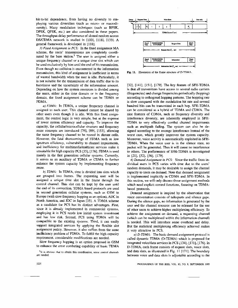
Demand assignment is inspired by the observation that voice conversation consists of talkspurts and silence gaps. During the silence gaps, no information is generated by the user and the channel resource can be released for the use of other users to achieve higher multiplexing efficiency. To achieve the assignment on demand, a requesting channel (which can be multiplexed within the information channel) is needed. This will introduce some overhead and delay. But the statistical multiplexing efficiency achieved makes it very attractive in PCS.
a ) D-TDMA: The basic demand assignment protocol is called dynamic TDMA (D-TDMA) which is proposed for integrated voice/data services in PCS [134], [171], [176]. In D-TDMA, each frame consists of request slots, voice slots, and data slots, as illustrated in Fig. 1 1 [171]. The boundary between voice and data slots is adjustable according to the
1220 PROCEEDINGS OF THE IEEE, VOL. 83, NO. 9, SEPTEMBER 1995
ratio of voice and data traffic. In D-TDMA, channel access is organized by an ALOHA random access scheme. Circuit mode reservation of slots over multiple D-TDMA frames is available for voice traffic. The remaining capacity in each frame is dynamically assigned to data users according to the first-in-first-out (FIFO) policy. Data users can only reserve a slot in the current frame. Because slots are assigned by a centralized method (through the base station), D-TDMA can be used to support multirate services. The performance of D-TDMA is simulated in [171] and analyzed in [124]. To further increase the capacity of D-TDMA, one may employ more efficient modulation schemes (e.g., quadrature amplitude modulation (QAM)) and lower bit rate voice coding [171]. But the inherent problem of D-TDMA is that a fixed reservation overhead is unavoidable and the boundaries between reservation and information slots and between voice and data slots are difficult to adjust in real time.
b) PRMA: Another TDMA-based demand assignment scheme proposed for PCS is Packet Reservation Multiple Access (PRMA) [48], [50], [103], [104]. PRMA combines random access with time division access and employs voice activity detection to improve the multiplexing efficiency. No resource is dedicated for channel access. All the slots in a frame are information slots. The data packet is used directly to access the channel. PRMA can also support integrated service by assigning voice and data different transmitting priorities according to their different traffic features. For example, since voice traffic is continuous and sensitive to delay, a voice user who succeeds in accessing the channel will be assigned a slot in consecutive frames until the end of the talkspurt. Data users transmitting short bursts cannot make reservation. They have to contend for the slot each time they have something to transmit. A user transmitting a long message, such as file transfer or electronic mail, can also make reservations, but with lower priority than voice. The performance of PRMA is investigated in many papers, considering various system scenarios (such as in fadinglshadowing channels, with capture, with dynamic channel allocation, with integrated voice/data services, with different user mobility, etc.) [50], [103], [1041, [124], [127], [173]. It is found that PRMA is very attractive in PCS because of its flexibility. In fact, there is a modified version of PRMA, called PRMA++, proposed as the radio access protocol for the Universal Mobile Telecommunication System (UMTS) in Europe [ 1661.
To improve the efficiency of the integrated voice/data PRMA system, one modified scheme is proposed, named the integrated PRMA (IPRMA) [174] where both voice and data traffic can make reservations. Voice packets make “vertical” reservations and data packets make “horizontal” reservations. The number of slots which can be reserved by data in a frame is controlled by the base station. This protocol is shown to be more efficient than basic PRMA.
The problem in PRMA is that using the whole informa- tion packet to access the channel is inefficient, especially when the traffic is heavy. With heavy traffic load, packet collision frequently occurs. It takes one packet duration
: Umr to base rtntion 0 : Barn dation to UIQ
I W D Mort dgnillcpnt digit
Ta: Bit trsnsmisdon time
LSD. Lead signincant d@t
td: Ropagatlon Pad proarlng delay
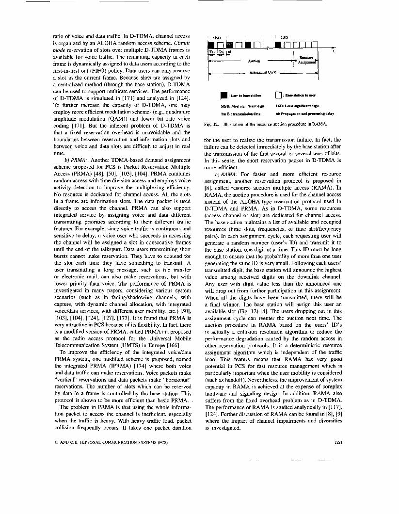
Fig. 12. Illustration of the resource auction procedure in RAMA.
for the user to realize the transmission failure. In fact, the failure can be detected immediately by the base station after the transmission of the first several or several tens of bits. In this sense, the short reservation packet in D-TDMA is more efficient.
c) RAMA: For faster and more efficient resource assignment, another reservation protocol is proposed in [SI, called resource auction multiple access (RAMA). In RAMA, the auction procedure is used for the channel access instead of the ALOHA-type reservation protocol used in D-TDMA and PRMA. As in D-TDMA, some resources (access channel or slot) are dedicated for channel access. The base station maintains a list of available and occupied resources (time slots, frequencies, or time slotlfrequency pairs). In each assignment cycle, each requesting user will generate a random number (user’s ID) and transmit it to the base station, one digit at a time. This ID must be long enough to ensure that the probability of more than one user generating the same ID is very small. Following each users’ transmitted digit, the base station will announce the highest value among received digits on the downlink channel. Any user with digit value less than the announced one will drop out from further participation in this assignment. When all the digits have been transmitted, there will be a final winner. The base station will assign this user an available slot (Fig. 12) [8]. The users dropping out in this assignment cycle can reenter the auction next time. The auction procedure in RAMA based on the users’ ID’S is actually a collision resolution algorithm to reduce the performance degradation caused by the random access in other reservation protocols. It is a deterministic resource assignment algorithm which is independent of the traffic load. This feature means that RAMA has very good potential in PCS for fast resource management which is particularly important when the user mobility is considered (such as handoff). Nevertheless, the improvement of system capacity in RAMA is achieved at the expense of complex hardware and signaling design. In addition, RAMA also suffers from the fixed overhead problem as in D-TDMA. The performance of RAMA is studied analytically in [117], [124]. Further discussion of RAMA can be found in [SI, [9] where the impact of channel impairments and diversities is investigated.
LI AND QIU: PERSONAL COMMUNICATION SYSTEMS (PCS) 1221

d) DRMA: The channel access in PRMA is not very efficient from the viewpoint of resource utilization. The fixed reservation overhead in D-TDMA and RAMA is un- avoidable and the ratio between reservation and information bandwidth is difficult to be adjusted dynamically according to traffic conditions. To overcome these shortcomings, another demand assignment protocol, called dynamic reser- vation multiple access (DRMA), is proposed in [122]. It is called dynamic reservation because the number of reservation slots and their positions in a frame change from time to time. In DRMA, each available information slot can serve as a set of reservation minislots. When the user is ready to transmit, it transmits the short reservation packet first in one of the reservation minislots in the next available slot. At the end of this set of reservation slots, the assignment is broadcasted by the base station (Fig. 13). This protocol preserves the short reservation packet feature of D-TDMA (RAMA) and does not introduce a fixed reservation overhead. Due to its minislot feature, the collisions in the channel access can be significantly reduced compared with PRMA. This modification can greatly improve the system performance especially under the integrated service scenario. Furthermore, no boundary needs to be set between voice and data slots as in D-TDMA and M A . More flexible and fairer channel sharing can be achieved. Numerical results are given in [124], indicating that DRMA is superior to the existing demand assignment protocols.
e) DH-TDMA: It is well known that in a narrowband system, the same frequency channel can be reused in distant cells to improve the capacity. But simultaneous transmissions in those co-channel cells may interfere with each other. Sufficiently large frequency reuse factor is necessary to protect the transmission. However, in the integrated system, different traffic may require different frequency reuse factors. In PCS, voice traffic is continuous and sensitive to transmission errors. This means large frequency reuse factor is necessary to reduce the co-channel interference. In a real system, this factor is generally from seven to 12.6 In contrast, data traffic is more bursty and has an inherent tolerance against interference. Errors can be corrected by retransmissions. This suggests a considerably smaller frequency reuse factor for data transmission than that for voice. In fact, employing contiguous “cells” with all base stations using the entire bandwidth may prove better in mobile data communications 1121. However, in all the above demand assignment protocols, the same frequency reuse factor is employed for both voice and data and designed according to the voice requirement. It will be inefficient for data traffic. This observation suggests that employing different frequency reuse factors for voice and data is a possible way to improve the integrated efficiency. In light of this observation, a protocol called data hopping TDMA (DH-TDMA) is proposed in [126]. In DH-TDMA, ordinary frequency planning is performed as in PRMA. In each frame, traffic slots are divided into data slots and
6Note that with cell sectorization and directional antenna, this factor can be smaller.
. At tbebcgbiq ofthe fourth dot
B At tbeend of thc fIAh dot
J( At tk end of tk Pix& slot
. . .
Fig. 13. Illustration of DRMA.
voice slots. In voice slots, only the preassigned transmission channel for that cell can be used to transmit voice packets according to the PRMA protocol. In data slots, all the channels (the whole bandwidth) can be used in each cell. The data user randomly selects one channel to transmit its packet according to the multichannel ALOHA protocol. This means that the frequency reuse factor of data is 1 and that of voice is C (C > 1 is a constant). The main purpose of this design is to take the frequency reuse feature of PCS into account. This feature is unique in the wireless system. It is shown in 11261 that in the microcellular environment (the signal suffers fading and shadowing), DH-TDMA outperforms PRMA and IPRMA.
There are still ongoing debates among experts with respect to the merits of various MA candidates for PCS, especially on the comparison of TDMA and CDMA [3], [31], [53], [123], [171]. Along with the development of technologies, some distinct features of CDMA can also be implemented in TDMA. For example, PRMA is a TDMA-based scheme taking advantage of voice activity; PRMA with capture provides the soft capacity feature [ 1271; dynamic channel allocation (DCA) eliminates the effort of frequency planning and provides the interference- limited feature; interference averaging system design can be implemented in TDMA by slow frequency hopping; various diversities and directional antenna can also be used in TDMA; etc. Therefore, the advantage of CDMA over TDMA may not be as large as that claimed by QUAL-
1222 PROCEEDINGS OF THE IEEE, VOL. 83, NO. 9, SEPTEMBER 1995

COMM [3]. It is believed that the inherent interference- limited feature of CDMA makes it potentially very valuable to provide high system capacity [123]. Even though this feature can also be achieved in TDMA by employing DCA, it will take more effort. On the other hand, TDMA has advantages to support integrated traffic, which is essential for the multimedia PCS. It is still too early to conclude which is better. The comparison of these two schemes in- volves too many factors and is very application-dependent, especially when DCA is employed in TDMA and multiuser detectiodinterference cancellation is used in CDMA. More careful studies are still needed to clarify this debate. In the United States, there are two standards, IS-54 for TDMA and IS-95 for CDMA. In the development of UMTS in Europe, there are also two different designs on the radio access. One is CDMA-based and the other is PRMA-based [ l l ] , [166].
5 ) Channel Allocation Schemes: The multiple access scheme provides the means to efficiently access the resources assigned to each cell. Another important issue related to the resource management is how to allocate these resources systemwide to achieve the highest spectrum efficiency. This issue is addressed by the channel allocation schemes.
To support the drastically increased demand for wireless communications, the cellular structure and the frequency reuse concept are introduced to improve the spectrum efficiency [89], [153]. In cellular systems, the service area is covered by cells and the total bandwidth is divided into channel sets. Each cell is assigned a set of channels. The same channel set can be reused in distant cells, thereby minimizing the co-channel interference. (The minimum reuse distance is called the co-channel reuse distance.) The call originated in the cell can only use the channels of that cell. If no free channel is available, the call will be blocked. This channel assignment strategy is called fixed channel allocation (FCA). FCA works very well in the first generation cellular systems which have regular cell structure and stable system configuration. With the introduction of microcells and picocells in PCS, FCA is becoming inadequate. First, frequency planning is getting more difficult and tedious in the microcellular environ- ment since accurate propagation predictions require a more detailed knowledge of the landscape than is required for large-area coverage design. Second, the fixed assignment strategy does not provide the flexibility for system re- configuration. To add or remove a base station needs a complete frequency replanning. Third, FCA is not flexible enough to handle the unpredicted traffic and abnormal interference scenarios, such as traffic jam, car accident, etc. Fourth, FCA is not suitable to provide “bandwidth on demand” which is important for multimedia services in PCS [7], [25], [40], [74], [167]. Therefore, more flexible channel allocation schemes are needed [34], [ 1621, [ 1811. One solution is to completely abandon the narrowband system concept and replace it by a spread spectrum system such as CDMA. The whole bandwidth in the CDMA system can be reused in every cell in the system. No frequency planning is needed and it is adaptive to the sys-
tem configuration changes. Another solution is to keep the narrowband system structure but use the frequency hopping concept to avoid frequency planning, e.g., FWTDMA. In this system, all available frequency is reused in each cell. Orthogonal frequency hopping patterns are employed in each cell and pseudo-orthogonal patterns between cells to eliminate the co-channel interference and hence achieve better system performance. In this section, we will only focus on the third solution being used in the current narrowband systems4ynamic channel allocation (DCA) schemes.
In DCA, generally speaking, there is some degree of flexibility for channel reuse subject to a minimum intercell reuse distance based on co-channel interference limitations. From the following discussion, we will see that DCA is more suitable for the nonuniform and unpredicted traffic scenarios than FCA. More importantly, the tedious work of frequency planning is reduced.
DCA strategies in the literature can be classified into four types: the macrodiversity strategy, the channel bor- rowing strategy, the flexible channel allocation strategy [ 1621, [ 1781, [ 18 13, and the self-adaptive channel allocation strategy [25], [26], [40], [162], [167]. The common feature of the first three types of DCA is that frequency planning is still necessary, but not as stringent as that in FCA. In the fourth type of strategy, frequency planning is totally avoided.
a) Macrodiversity strategy: The macrodiversity strat- egy is actually a variation of FCA. The channels are still permanently assigned to base stations. When a call is originated, the mobile station will select the most preferable base station and try to establish a connection to it. The preference is defined according to the received signal strength or the signal-to-noise ratio. If all the channels are busy in the target base station, the second most preferable base station is tried, and so forth. With this method, the channel accessed by the user is not confined in the current cell where he is physically. Traffic balancing is achieved automatically, i.e., this strategy is traffic adaptive. Higher spectrum efficiency can be obtained than that of the traditional FCA system.
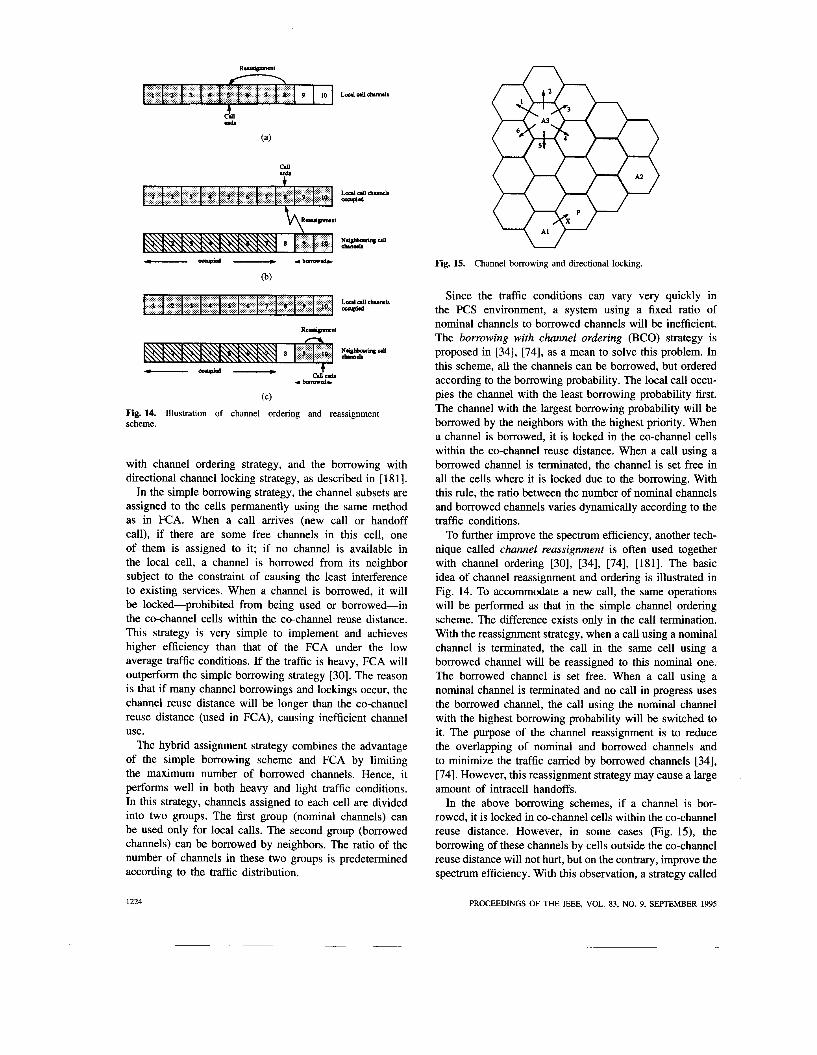
b ) Channel borrowing strategy: One drawback of FCA is that it is very hard to handle time and spatial changes in offered traffic. In a real system, due to nonuniform traffic distribution, it is quite common for congestion to occur in one cell but not in its neighbors. When this happens, all the channels in the congested cell will be occupied and a new call will be blocked because no channel is available. But at the same time, there may still be a few channels available in its neighboring cells. To efficiently use the spectrum to provide higher system capacity in this case, the borrowing concept is proposed. The basic idea is that the busy cell can borrow free channels from its neighbors on the basis that they will cause the least harm to neighboring cells [74]. Generally, it borrows from the adjacent cell which has the largest number of free channels. There are four types of borrowing strategies: the simple borrowing strategy, the hybrid assignment strategy, the borrowing
LI AND QIU: PERSONAL COMMUNICATION SYSTEMS (PCS) 1223
A
Fig. 15. Channel borrowing and directional locking.
Since the traffic conditions can vary very quickly in the PCS environment, a system using a fixed ratio of
L c a l d C h d # ossupd
nominal channels to borrowed channels will be inefficient. The borrowing with channel ordering (BCO) strategy is proposed in [34], [74], as a mean to solve this problem. In this scheme, all the channels can be borrowed, but ordered according to the borrowing probability. The local call occu-
R-1
N - 4 o h m o h
(C) Fig. 14. Illustration of channel ordering and reassignment scheme.
with channel ordering strategy, and the borrowing with directional channel locking strategy, as described in [ 1811.
In the simple borrowing strategy, the channel subsets are assigned to the cells permanently using the same method as in FCA. When a call arrives (new call or handoff call), if there are some free channels in this cell, one of them is assigned to it; if no channel is available in the local cell, a channel is borrowed from its neighbor subject to the constraint of causing the least interference to existing services. When a channel is borrowed, it will be locked-prohibited from being used or borrowed-in the co-channel cells within the co-channel reuse distance. This strategy is very simple to implement and achieves higher efficiency than that of the FCA under the low average traffic conditions. If the traffic is heavy, FCA will outperform the simple borrowing strategy [30]. The reason is that if many channel borrowings and lockings occur, the channel reuse distance will be longer than the co-channel reuse distance (used in FCA), causing inefficient channel use.
The hybrid assignment strategy combines the advantage of the simple borrowing scheme and FCA by limiting the maximum number of borrowed channels. Hence, it performs well in both heavy and light traffic conditions. In this strategy, channels assigned to each cell are divided into two groups. The first group (nominal channels) can be used only for local calls. The second group (borrowed channels) can be borrowed by neighbors. The ratio of the number of channels in these two groups is predetermined according to the traffic distribution.
1224
pies the channel with theleast borrowing probability first. The channel with the largest borrowing probability will be borrowed by the neighbors with the highest priority. When a channel is borrowed, it is locked in the co-channel cells within the co-channel reuse distance. When a call using a borrowed channel is terminated, the channel is set free in all the cells where it is locked due to the borrowing. With this rule, the ratio between the number of nominal channels and borrowed channels varies dynamically according to the traffic conditions.
To further improve the spectrum efficiency, another tech- nique called channel reassignment is often used together with channel ordering [30], [34], [74], [181]. The basic idea of channel reassignment and ordering is illustrated in Fig. 14. To accommodate a new call, the same operations will be performed as that in the simple channel ordering scheme. The difference exists only in the call termination. With the reassignment strategy, when a call using a nominal channel is terminated, the call in the same cell using a borrowed channel will be reassigned to this nominal one. The borrowed channel is set free. When a call using a nominal channel is terminated and no call in progress uses the borrowed channel, the call using the nominal channel with the highest borrowing probability will be switched to it. The purpose of the channel reassignment is to reduce the overlapping of nominal and borrowed channels and to minimize the traffic carried by borrowed channels [34], [74]. However, this reassignment strategy may cause a large amount of intracell handoffs.
In the above borrowing schemes, if a channel is bor- rowed, it is locked in co-channel cells within the co-channel reuse distance. However, in some cases (Fig. 15), the borrowing of these channels by cells outside the co-channel reuse distance will not hurt, but on the contrary, improve the spectrum efficiency. With this observation, a strategy called
PROCEEDINGS OF THE IEEE, VOL. 83, NO. 9, SEPTEMBER 1995
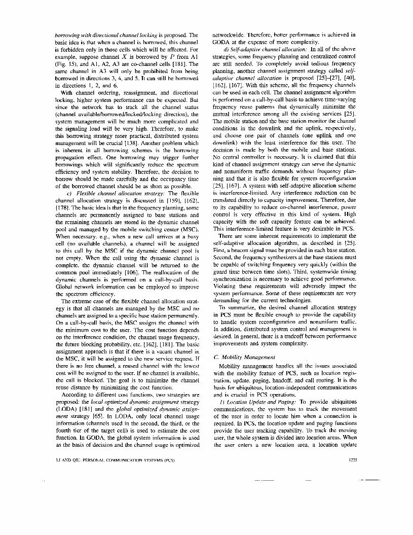
borrowing with directional channel locking is proposed. The basic idea is that when a channel is borrowed, this channel is forbidden only in those cells which will be affected. For example, suppose channel X is borrowed by P from A1 (Fig. 15), and Al, A2, A3 are co-channel cells [181]. The same channel in A3 will only be prohibited from being borrowed in directions 3, 4, and 5. It can still be borrowed in directions 1, 2, and 6.
With channel ordering, reassignment, and directional locking, higher system performance can be expected. But since the network has to track all the channel status (channel available/borrowed/locked/locking direction), the system management will be much more complicated and the signaling load will be very high. Therefore, to make this borrowing strategy more practical, distributed system management will be crucial [138]. Another problem which is inherent in all borrowing schemes is the borrowing propagation effect. One borrowing may trigger further borrowings which will significantly reduce the spectrum efficiency and system stability. Therefore, the decision to borrow should be made carefully and the occupancy time of the borrowed channel should be as short as possible.
c) Flexible channel allocation strategy: The flexible channel allocation strategy is discussed in [ 1591, [ 1621, [178]. The basic idea is that in the frequency planning, some channels are permanently assigned to base stations and the remaining channels are stored in the dynamic channel pool and managed by the mobile switching center (MSC). When necessary, e.g., when a new call arrives at a busy cell (no available channels), a channel will be assigned to this call by the MSC if the dynamic channel pool is not empty. When the call using the dynamic channel is complete, the dynamic channel will be returned to the common pool immediately [106]. The reallocation of the dynamic channels is performed on a call-by-call basis. Global network information can be employed to improve the spectrum efficiency.
The extreme case of the flexible channel allocation strat- egy is that all channels are managed by the MSC and no channels are assigned to a specific base station permanently. On a call-by-call basis, the MSC assigns the channel with the minimum cost to the user. The cost function depends on the interference condition, the channel usage frequency, the future blocking probability, etc. [162], [181]. The basic assignment approach is that if there is a vacant channel in the MSC, it will be assigned to the new service request. If there is no free channel, a reused channel with the lowest cost will be assigned to the user. If no channel is available, the call is blocked. The goal is to minimize the channel reuse distance by minimizing the cost function.
According to different cost functions, two strategies are proposed: the local optimized dynamic assignment strategy (LODA) [I811 and the global optimized dynamic assign- ment strategy [65]. In LODA, only local channel usage information (channels used in the second, the third, or the fourth tier of the target cell) is used to estimate the cost function. In GODA, the global system information is used as the basis of decision and the channel usage is optimized
networkwide. Therefore, better performance is achieved in GODA at the expense of more complexity.
d) Self-adaptive channel allocation: In all of the above strategies, some frequency planning and centralized control are still needed. To completely avoid tedious frequency planning, another channel assignment strategy called self- adaptive channel allocation is proposed [25]-[27], [40], [ 1621, [ 1671. With this scheme, all the frequency channels can be used in each cell. The channel assignment algorithm is performed on a call-by-call basis to achieve time-varying frequency reuse patterns that dynamically minimize the mutual interference among all the existing services [25]. The mobile station and the base station monitor the channel conditions in the downlink and the uplink, respectively, and choose one pair of channels (one uplink and one downlink) with the least interference for this user. The decision is made by both the mobile and base stations. No central controller is necessary. It is claimed that this kind of channel assignment strategy can serve the dynamic and nonuniform traffic demands without frequency plan- ning and that it is also flexible for system reconfiguration [25], [ 1671. A system with self-adaptive allocation scheme is interference-limited. Any interference reduction can be translated directly to capacity improvement. Therefore, due to its capability to reduce co-channel interference, power control is very effective in this kind of system. High capacity with the soft capacity feature can be achieved. This interference-limited feature is very desirable in PCS.
There are some inherent requirements to implement the self-adaptive allocation algorithm, as described in [25]. First, a beacon signal must be provided in each base station. Second, the frequency synthesizers at the base stations must be capable of switching frequency very quickly (within the guard time between time slots). Third, systemwide timing synchronization is necessary to achieve good performance. Violating these requirements will adversely impact the system performance. Some of these requirements are very demanding for the current technologies.
To summarize, the desired channel allocation strategy in PCS must be flexible enough to provide the capability to handle system reconfiguration and nonuniform traffic. In addition, distributed system control and management is desired. In general, there is a tradeoff between performance improvements and system complexity.
C. Mobility Management Mobility management handles all the issues associated
with the mobility feature of PCS, such as location regis- tration, update, paging, handoff, and call routing. It is the basis for ubiquitous, location-independent communications and is crucial in PCS operations.
1) Location Update and Paging: To provide ubiquitous communications, the system has to track the movement of the user in order to locate him when a connection is required. In PCS, the location update and paging functions provide the user tracking capability. To track the moving user, the whole system is divided into location areas. When the user enters a new location area, a location update
LI AND QRJ: PERSONAL COMMUNICATION SYSTEMS (PCS) 1225

Fig. 16. Illustration of location and paging areas.
transaction will be performed to inform the network of his new location. This corresponds to updating the visitor location register (VLR) and home location register (HLR). When a new call is destined to him, the database query is performed to find his actual location and the paging function is executed to alert him. With this location information, a specified area is paged instead of the whole system.
The location update process can be performed manually or automatically. Manual location updates are quite simple. The user needs only key in his PTN at the new location to inform the network his current position. Automatic updates are performed by the mobile terminal and are transparent to the user.
A functional location update procedure is described in [172] which is summarized as follows. The base station (BS) continuously broadcasts, on the broadcast channel, the identity of its location area. The mobile station monitors the broadcast channels of BS's continuously. When a location change (different location area identity) is detected, it will report the new location to the BS which will route it to the appropriate VLR. The VLR will send the new location information to the HLR of this user. The HLR will inform the old VLR to delete the entry associated with this user and send a copy of the service profile to the new VLR. An alternative implementation sends the service profile to the new VLR only when necessary, such as when a new call arrives for this user, or when he wants to make a call.
Location updates can be triggered by three methods: the timing method, the distance method, and the region method [148], [165]. In the first two methods, after a specific amount of time has elapsed or a specific amount of distance has been traveled, the location update procedure will be started automatically even though the user may still be in the same location area. Since this will cause many unnecessary updates and cannot perform prompt registration when necessary, they are not suitable for PCS. Therefore, the region method is widely used. With this method, the whole system is divided into location areas. The user triggers the location update function upon entering a new location area.
The system cost of the location update and paging consists of two parts. One part is mainly due to the signaling
1226
Fig. 17. Illustration of asymmetric location and paging areas.
traffic caused by the message exchanges during the update and the paging processes. The method to reduce this cost is the proper design of location areas and paging areas [41, [5]. Another part of the cost is due to the huge volume of database transactions involved in the location update and paging. Even though the location and paging areas are optimized, the centralized database may still become a bottleneck when the number of users in the system is large and the user mobility is high [125]. This problem will be discussed in the distributed database section. Here, we will focus on the location area design.
Several practical locatiodpaging area design strategies can be found in the literature. There are two extreme ones which are the simplest and most inefficient. The first one requires the user to update its location in each cell. The exact position of the user is known to the network. The paging traffic is minimized at the expense of heavy update traffic, especially when the cell size is small and frequent handoffs occur. Another extreme strategy requests no location update at all. When a connection request arrives, the whole system is paged. In this case, the update cost is minimized, but the paging cost is very high. The resulting traffic of both schemes depends very much on the system size [116].
A more efficient method is to split the whole system into location areas and paging areas each of which consists of multiple cells. The user's location information is updated whenever he enters a new location area. When a connection request arrives, the relevant cells in the user's current location area will be paged (Fig. 16) [116]. Here we assume that the paging area is equal to the location area. The optimal size of the location area depends on the user mobility and the call arrival rate.
The observation [116], [I481 that the paging traffic is proportional to the size of the paging area and the location update traffic is inversely proportional to the square root of the size of the location area suggests that a smaller paging area can be used to further reduce the signaling traffic (Fig. 17). The size of the location (paging) area can be optimized according to the traffic conditions [107].
The signaling cost can be further reduced if the unique features of different users are taken into account. For example, quasistationary users cause few location updates, which suggests smaller location areas to improve the paging efficiency. Fast moving users generate lots of location
PROCEEDINGS OF THE IEEE, VOL. 83, NO. 9, SEPTEMBER 1995

.... .
Fig. 18. location update traffic.
Illustration of the grouping concept to distribute the
updates, which means larger location areas are suitable. Grouping can be used to achieve high system performance. Users are divided into different groups. Each group has its own location management parameters (area size, etc.) optimized according to the features of this group (mobility, call arrival rate). Therefore, location management will be optimized for all kinds of mobility and call patterns, which obviously reduces the total system cost.
There is another very important fact influencing the proper operation of the system. All the location updates occur at the boundary cells of location areas. If all users have the same location areas, then the signaling traffic in boundary cells will be much higher than other cells inside the same location area. This causes imbalance in the signaling system. We can also use grouping to solve this problem. Users are divided into groups, each of which is assigned its own location areas. Location areas of different groups are mapped to different physical areas in the system to provide almost uniform update traffic (Fig. 18) [116].
When a user moves along the boundary of two location areas, the location update traffic may be increased due to user zigzagging (moving back and forth) between adjacent areas. This problem can be solved by introducing the overlapping area concept (Fig. 19). Only when the user crosses the overlapping region will location update occur. In the overlapping region, the user only belongs to one location area and no updates are required. This overlapping region avoids the “ping-pong” effect in the location update process [23], [116].
In [l lo], a new location update method called multi-layer location update is proposed. It employs the above overlap- ping area and grouping concept to avoid unnecessary update and to distribute the signaling traffic.
Since the traffic characteristic of users such as the moving speed and the call amval rate vary from time to time, the dynamic adjustment of location management parameters (locatiodpaging area size) of the individual user is desired to optimize the system performance. A dynamic scheme is proposed in [177]. This scheme promises to minimize the update signaling traffic and paging in an optimal way.
Besides the above strategies, another approach is based on the predictive method. It predicts the movement of users
0 L-m-I Q w - 1 ov--
Fig. 19. Illustration of the “Ping-Pong” effect in location update and the overlapping area concept
based on historical data to optimize the update and paging performance. Details can be found in [42], [1391, [1491.
To summarize, in order to achieve cost-efficient location update and paging in PCS, the characteristics of different traffic flows (mobility pattern and call arrival rate) have to be taken into account to optimize the location manage- ment parameters. These parameters should be dynamically adjustable. Unnecessary update and paging can be avoided by the overlapping area concept and predictive methods. In addition, the signaling traffic needs to be uniformly distributed in the system to facilitate the signaling system design and operation.
2) Call Routing Schemes: Through the location registra- tion and update operation, the network will know the user’s current location. This location information is stored in the user’s VLR and HLR in the form of a routing number. When the user’s PTN is dialed, it is the routing function that translates the PTN to the corresponding routing number. With this number, the paging function can be performed to locate the user, alert the user of the incoming call, and establish the connection to him. The call routing function is essential for efficient connection establishment and for maintaining the connection, especially when the user is moving. The main concerns in the design of the call routing scheme are the routing cost (the expense of network resources and the amount of signaling traffic) and the routing delay.
Call routing is based on the routing number which is a temporary number assigned by the VLR where the user is currently visiting. It is stored in the user’s HLR to identify the user’s current location. This number will be reassigned when the user enters a new location area controlled by a new VLR, and updated in the user’s HLR. The routing number concept has been used in GSM [129], where it is called the mobile station roaming number (MSRN).
The call management functions of the intelligent network help to support correct and efficient call routing. The network entities involved are various databases, such as VLR, HLR, EIR, AUC, and the PCS local switch (or the ATM switch supporting PCS service). When a PTN is dialed, the HLR of the corresponding user will be interrogated. Database query is performed to translate the PTN to the corresponding routing number. Then different routing approaches can be adopted based on the routing number. Three routing methods are described in [18],
LI AND QIU: PERSONAL COMMUNICATION SYSTEMS (PCS) 1221

0) N d c.ll Serupto
(1) Qusry: SAC-888-8888
(2) “Route Y) 212- LA. Washington D. C.
(a)
*wyorL o\ (2) Call Faward to
(1) N a r d Call 202888-8888
LA.
(3) Normal Call Sdupto
(1) UM m888-8888
(2) %buc“R.roucc to 21- LA. Wphia@m D. C.
(C)
Fig. 20. Illustration of three routing methods.
namely, the “800” method, the RACF method, and the Crankback method. Their common feature is that a local switch supporting PCS service is necessary. We will use an example to illustrate these three methods. Assume Alex in Los Angeles wants to call Alice whose home area is in Washington, DC, and Alice is visiting New York right now. Alex dials the PTN of Alice. How is the call routed to Alice?
The “800” method follows the same rule as that used in the Intelligent Network 800 Service to route the call. The specific PTN numbering plan is needed to allow the switch to distinguish the dialed PTN from non-PTN. In this numbering plan (it will be described in detail in the next section), the specific service access code (SAC) is explicitly defined in the user’s number to indicate PCS service. When the SAC is detected, the network interrogates the HLR of Alice to get the routing number and set up a direct route to Alice’s current location. This procedure is shown in Fig. 20(a) [18].
The RACF method uses the switch feature known as Call Forwarding to route the calls to the destination indirectly. No special numbering plan is needed. When Alice registers in the VLR of New York, her routing number in her HLR will be updated. When Alex makes a call to her, he is always connected to Alice’s home switch-switch B. Switch B will forward the call to Alice’s new location (switch C) directly based on the appropriate routing num- ber. The routing procedure is shown in Fig. 20(b). This
method is quite simple in the call setup stage. No feedback is necessary. But since the whole conversation has to be rerouted by the home switch, more network resources are consumed and longer routing delay is incurred.
The third method is called the Crankback method which is a network-based call forwarding scheme based on the SS7 signaling system. It is quite similar to the “800” method except that the SS7 signaling protocol is employed for database interrogation and no specified numbering plan is needed. The PCS call is distinguished in the switch on a number-by-number basis. (The switch maintains a database which can distinguish the PCS number from the ordinary one.) The SS7 Initial Access Message (IAM), which is used in the normal SS7 call setup procedure, is employed to initiate the call setup. If Alice is at home, the response message will indicate that normal call setup is completed. If Alice is out of town, the routing number will be sent back in the response message. With the routing number, the direct connection to Alice will be established. This procedure is shown in Fig. 20(c).
3) Handoff Strategies: Handoff is another important function of mobility management. It is unique in cellular systems and especially crucial to support global roaming in PCS. Handoff denotes the process of changing the channel (frequency, time slot, spreading code, or combinations of them, according to the multiple access scheme used) associated with the current connection to maintain acceptable service quality or to provide better service. It is often initiated either by cell boundary crossing or deteriorated service quality in the current channel. With the penetration of PCS, the microcell and the hybrid cell (macro-, micro-, pico-) structure are exploited to support the drastically increased demand. The smaller cell size and the variable propagation conditions in microcells introduce much more frequent handoffs than ever before. Poorly designed handoff strategy will generate very heavy signaling traffic and worsen service quality.
To maintain acceptable service to the moving user, basic requirements for PCS handoff operations are the execution speed and reliability as well as transparency to the user [IO]. In addition, due to the multiple types of services supported in PCS, the handoff strategy needs to take different features of these services into account, i.e., the ideal handoff process is service-dependent. For example, voice transmission is very sensitive to interruption. On the other hand, loss of data has little impact on the data performance since it can be recovered by the retransmission procedure. Therefore, a successful handoff is very important to voice, but not as critical to data (the data here is not delay-sensitive).
The handoff process usually consists of two phases: the handoff initiation phase and the handoff execution phase. In the handoff initiation phase, the service quality is monitored in order to decide when to trigger the handoff. In the handoff execution phase, the allocation of new resources to the handoff is performed [82]. In the following, we will discuss the handoff initiation process first.
a ) Handoff initiation phase: The handoff may be ini- tiated under three situations: 1) when the received signal
1228 PROCEEDINGS OF THE IEEE, VOL. 83, NO. 9, SEPTEMBER 1995
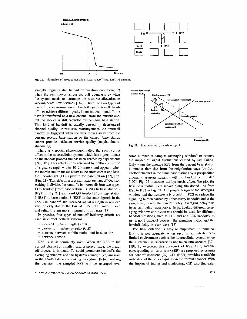
Received signal strength
strength degrades due to bad propagation conditions; 2) when the user moves across the cell boundary; 3) when the system needs to rearrange the resource allocation to accommodate new services [147]. There are two types of handoff processes-intercell handoff and intracell hand- off-to achieve different goals. In an intracell handoff, the user is transferred to a new channel from the current one, but the service is still provided by the same base station. This kind of handoff is usually caused by deteriorated channel quality or resource rearrangement. An intercell handoff is triggered when the user moves away from the current serving base station or the current base station cannot provide sufficient service quality (maybe due to shadowing).
There is a special phenomenon called the street comer effect in the microcellular system, which has a great impact on the handoff process and has been verified by experiments [24], [86]. This effect is characterized by a 20-30 dB drop of signal strength within 10-20 meters and appears when the mobile station makes a tum at the street corner and loses the line-of-sight (LOS) path to the base station [22], [52] (Fig. 21). This effect has a great impact on handoff decision making. It divides the handoffs in microcells into two types: LOS handoff [from base station 1 (BS1) to base station 2 (BS2) in Fig. 211 and non-LOS handoff [from base station 1 (BS1) to base station 3 (BS3) in the same figure]. In the non-LOS handoff, the received signal strength is reduced very quickly due to the loss of LOS. The handoff speed and reliability are more important in this case [13].
In practice, four types of handoff initiating criteria are used in current cellular systems.
received signal strength (RSS) carrier to interference ratio (CIR) distance between mobile station and base station network criteria.
RSS is most commonly used. When the RSS in the current channel is smaller than a preset value, the hand- off process is initiated. To avoid premature handoffs, the averaging window and the hysteresis margin ( H ) are used in the handoff decision making procedure. Before making the decision, the sampled RSS will be averaged over
street BS3
BS1 A C Distana
Fig. 21. Illustration of street comer effect, LOS handoff, and non-LOS handoff.
DauoafmmBS1
Fig. 22. Illustration of hysteresis margin H.
some number of samples (averaging window) to remove the impact of signal fluctuations caused by fast fading. Only when the average RSS from the current base station is smaller than that from the neighboring ones (or from another channel in the same base station) by a prespecified amount (hysteresis margin) will the handoff be initiated [102]. Fig. 22 illustrates the hysteresis effect. We plot the RSS of a mobile as it moves along the dotted line from BS1 to BS2 in Fig. 21. The proper design of the averaging window and the hysteresis is crucial in PCS to reduce the signaling burden caused by unnecessary handoffs and at the same time, to keep the handoff delay (averaging delay plus hysteresis delay) acceptable. In particular, different aver- aging window and hysteresis should be used for different handoff situations, such as LOS and non-LOS handoffs, to get a good tradeoff between the signaling traffic and the handoff delay in each case [ 131.
The RSS criterion is easy to implement in practice. But it is not adequate when used in an interference- limited environment such as the microcellular system, since the cochannel interference is not taken into account [37], [39]. To overcome this drawback of RSS, CIR, and the corresponding bit error rate (BER) are proposed as criteria for handoff decisions [29]. CIR (BER) provides a reliable indication of the service quality in the current channel. With the impact of fading and shadowing, CIR also fluctuates
LI AND QIU: PERSONAL COMMUNICATION SYSTEMS (PCS) 1229

when the mobile station is moving. A hysteresis margin and an averaging window are also necessary to provide accurate handoffs.
Note that although the distance between the base station and the user is the most obvious trigger for handoff, it is not the most important one in microcells. Due to the particular environment surrounding the user, it is very possible that the closer base station provides worse quality than the farther one. Thus accurate handoff decisions depend not only on the geometric description but also on the specific propagation model. (A commonly accepted propagation model of microcells has not been developed, but some char- acteristics are described in [20].) Therefore, the distance between the mobile and base station is usually used as an auxiliary criterion to CIR or RSS to provide reliable and accurate handoff initiation.
Deteriorated quality is not the only reason for handoffs. To accommodate more users in a cell or to balance the traffic between cells, it is sometimes necessary to rearrange the resources in the system, e.g., moving an ongoing call from the current channel to a new one. In this situation, the handoff is triggered by the network. The main purpose of this kind of handoff is to provide higher system capacity and better system performance by employing global system information [6], [39].
b) Hundoff execution phase: After making the handoff decision, resources need to be allocated to the mobile at the new base station. From the view point of the users, the forced termination of ongoing calls is much less desirable than simply blocking new ones. Therefore, the resource assignment should give priority to handoff calls. Three types of priority disciplines are proposed. The first one uses the Reserved Channel concept, which reserves a few channels, say N , (frequency, time slot, spreading code, etc.) and dedicate them for handoff use. Suppose there are C channels in a cell. The other (C - N ) channels can be shared between handoff calls and new calls. If the number of free channels is less than or equal to N , the new call will be blocked. The handoff calls can still gain access to the system until there is no available channel. This method reduces the failure rate of handoff calls at the expense of increasing the new call blocking rate and reducing the spectrum efficiency. The performance of this priority scheme is investigated in [54], [81], [180].
Another priority discipline is called N-Times Retry [87] where the unsuccessful handoff requests can be resubmitted for a specific number of times at predetermined time intervals. This scheme exploits the fact that the user will spend some time in the handoff area, i.e., in this area, the user can still receive acceptable service through the old connection before the new one is established. More retries give the handoff calls more opportunity to access the channel than the new ones. Therefore, the handoff failure rate will be reduced. The new call blocking rate remains almost unchanged since all channels are available for the new calls. According to [87], this scheme has better performance than the Reserved Channel scheme and no handoff queue is needed.
The third priority scheme gives priority to the handoff calls by setting up the handoff queue. The handoff call can be queued if no channel is available when the request is presented. Such queuing works because the MS will spend some time in the handoff area where it is physically capable of communicating with both the current and target BS’s. The fact that a successful handoff can take place anywhere in this interval gives a certain amount of tolerance in the de- lay for the actual channel assignment to the handoff request. There are two types of priority schemes-the FIFO scheme and the measurement-based priority scheme [164]. In the FIFO scheme, the handoff request is queued according to the request arrival time. The request which arrives first gets the highest priority to access the channel. The priority will be increased automatically as time elapses. This scheme does not need to change the priority dynamically according to the actual quality of the service so that a reordering and sorting algorithm is not needed. The implementation of this scheme is relatively simple. The performance of FIFO scheme is investigated in [43], [81], [1301, 11311, [1641. The mathematical model is developed in [59], [164].
Another priority assignment discipline is based on the measurement of degradation rate in the radio channel. Due to different velocities and channel conditions of users, the service quality of some users will degrade much faster than the others. This means that a user presenting a later handoff request may need faster handoff than another one which submits the request earlier. Therefore, if the channel is assigned according to the arrival time of the requests such as in the FIFO queuing scheme, the call corresponding to the later request will be lost. This problem is solved by the measurement-based priority strategy proposed in [ 1641. In this strategy, the priority of each user is reassigned after a certain time interval according to the current service quality. It ensures the user in the most urgent situation gets access to the system first. The problem of this priority scheme is that it is complicated compared to the FIFO one. The network needs to monitor the users’ service quality continuously. A reordering and sorting algorithm is needed to reassign the priority. The network loading is increased. But the benefits include increased spectrum efficiency and reduced forced termination of handoff calls with a slightly increased new call blocking rate. This measurement-based scheme is analyzed in [162]-[ 1641.
Besides the above strategies, many other methods are proposed to ensure the handoff performance in microcells. For example, the subrating scheme is presented in [81]. When a handoff call enters a busy cell (no channel avail- able), an occupied full-rate channel can be divided into two half-rate channels to accommodate it. When there is a free channel, one of the half-rate calls will be moved there, freeing up a half-rate channel which will be merged with the other half-rate one to provide full-rate service again. This scheme trades the service quality with the system capacity. System information may also be used to provide better handoff performance. For example, a velocity-adaptive handoff strategy is proposed in [ 141 and a direction-based handoff strategy is proposed in [ 131, where
1230 PROCEEDINGS OF THE IEEE, VOL. 83, NO. 9, SEPTEMBER 1995
Table 4 Summary of the Four Kinds of Handoff Processes
Protocol
-NCHO (centralized)
MAHO (decentralized)
MCHO (decentralized)
Soft Handoff (MAHO)
Mobile Station I Base
Passive
Make periodic measurements on current and neighboring channels Send results to BS
current connection Send measurement
current connection
Make handoff decision and inform MSC and MS or send the measurement results to
1 MSC I Monitor the channel Monitor the
channel quality Select new BS
Make the handoff decision
quality Send the measurement results to the MS Send the handoff decision to the MSC
Initiate the handoff request
Select new BS
Make the handoff decision and inform the MSC or send the measurement results to the MSC
Mobile Switching Center Make handoff decision
Inform new BS
Supervise the handoff process and inform the new BS
or make the handoff decision and inform the new BS
Supervise the handoff process and inform the new BS
Supervise the handoff process and inform the new BS
or make the handoff decision and inform the new BS
the user’s velocity and the moving direction are used, respectively, to provide more accurate handoffs.
Depending on who initiates and executes the hand- offs, there are three types of handoff processes which are called network controlled handof (NCHO), mobile assisted handofS (MAHO), and mobile controlled handof (MCHO), respectively. Their features are summarized in Table 4 [52], [97], [162]. Each of them has its own advantages and disadvantages and satisfies different requirements. But the MAHO and the MCHO will be much more preferable in PCS since they distribute the control between the mobile and the base station, which drastically reduces the signaling traffic and the handoff delay. This is a very desirable feature in PCS design because of the frequent handoffs in microcells. In the same table, the characteristic of soft hundoflis also illustrated. Soft handoff is actually one kind of mobile assisted handof (MAHO) with the employment of macrodiversity. The basic idea is that when the user enters the handoff area, it can establish more than one connection to base stations. Only when the new base station can provide adequate service alone will the old connection be relinquished. This scheme is a good example of the make-before-break concept [ 1431, which ensures an available good reception in the new channel before breaking the old one. Soft handoff can provide reliable and fast handoff at the expense of expensive hardware (both base station and mobile station) and complexity in system man-
Handoff Time
Several seconds
1 s in GSM
100 ms in DECT
Irrelevan
High Intercell
Sample System
AMPS TACS NMT
GSM
DECT
QUAL- COMM CDMA system
agement, operation, and maintenance as well as a slightly reduced system capacity and more co-channel interference. Therefore, there is a tradeoff among handoff reliability, service quality, system complexity, co-channel interference, system capacity, etc. For more information about soft handoff [3], [ 1121, [ 1421, [ 1431 are recommended.
Some efforts are made to model the handoff problem mathematically. A simple Markovian model is given in [75] to model the basic handoff process. In [130]-11321, a multidimensional birth-death process is used to model the handoff problem in PCS. Using this model, a broad class of handoff problems, characterized by nonhomoge- neous systems, imperfect handoff initiation, various priority schemes, single and multicall handoff scenarios, various mobility patterns, etc., can be analyzed. A two-dimensional Markovian model can be found in [180] to analyze the priority reservation handoff process.
There is a new problem in the handoff strategy which is associated with the hybrid cell structure used in PCS. It is known that to satisfy the multimobility (stationary, low speed, high speed) and multienvironment (office building,, urban area, rural area) requirements of PCS,,the uniform cell structure (either macro-, micro-, or pico-) is not suffi- cient. To take these unique features of PCS into account, a hybrid cell structure is proposed in [36], [105], [109], which is illustrated in Fig. 23. In this structure, high density users such as in office buildings are supported by picocells. The
LI AND QIU: PERSONAL COMMUNICATION SYSTEMS (KS) 1231

I '.
00
8 , Macrocell U0 I ,
_----_ ,
I , I microcell
Fig. 23. Hybrid cell structure for PCS.
users in urban areas with low mobility are supported by microcells. The high speed users or the users in rural areas are supported by macrocells to avoid frequent handoffs and to provide cost-efficient service (Sometimes, the satellite system is also involved). There are some impacts of this hybrid cell structure on the handoff strategy design. The most obvious one is that hand up and hand down processes are defined to represent the call transfer between different cell layers as well as the handoff for the call transfer at the same cell level. It is proposed that macrocells can be used to accommodate the overflow handoffs in the lower level cells temporarily (handup). Once there is an available channel in the lower level cells, this call will be handed down. Some researchers investigate the impact of this hybrid cell structure on the handoff performance [60], [641, [881, [156].
4 ) Distributed Database: The database in PCS plays an important role in the mobility-related system operations. It is the database that records the relevant information of the user (for instance, the location information, the service profile, etc.), traces the user location by updating the relevant database entry, and maps the user's personal number to his (her) physical location. Among all the services involving database operations, the location update (when the user roams to a new location area or turns on the power) and the location query (during call setup and call routing) are the most important ones. The frequent queries and updates may make the database a bottleneck when the centralized architecture is employed [93]. For example, Fig. 24 illustrates the database structure used in GSM. Each VLR serves one particular location area. Several VLR's are connected to an HLR. The HLR contains the information of all users residing in its service area. The information stored in VLR is only a subset of those in HLR. In [98], it is
I I h
Fig. 24. Database system in GSM.
estimated that to provide PCS service to 2.87 million people under reasonable system parameters (128 VLR's per HLR, average call origination rate is 1.4 callshdterminal, average speed of a mobile is 5.6 km/h, etc.), the query rate to HLR is more than a thousand per second. The database transaction rate in PCS has also been estimated in many other papers under different system scenarios [84], [93]. The general conclusion is that the database transaction rate will be very high. Therefore, in PCS, a hierarchical distributed database system is preferred in order to avoid the congestion inherent in a centralized database design [93].
The adopted numbering scheme in PCS has a great impact on the design of the distributed database system (see also the section about the numbering plan). If the location-dependent numbering scheme is employed as the first step toward PCS, the problem is less challenging since the location information is explicitly included and the scale of database can be relatively smaller. One such distributed database system architecture is proposed in [170], as illustrated in Fig. 25. The possible numbering
1232 PROCEEDINGS OF THE IEEE. VOL. 83, NO. 9, SEPTEMBER 1995

h b l r “Mta
Fig. 25. A proposed database system architecture with loca- tion-dependent numbering scheme.
structure is also suggested by [ 1701 and shown in the same figure. With this strategy, there is no location information entry associated with a mobile when it stays at its home location since its location is indicated explicitly by its number. Only when the user changes its location will its location information be added to the databases in the corresponding level, i.e., the database keeps the information only when necessary. It is shown in [ 1701 that the number of entries in the database at each level can be greatly reduced and the congestion in databases can be eliminated.
However, this strategy does not work when the location- independent PTN is adopted. Without location information in F”, a large logically centralized database (although it may be physically distributed) seems unavoidable. Every user in the system has an entry in this database. Searching this large database will be very time-consuming and may cause congestion. Since the database size can hardly be reduced with the location-independent PTN, one of the remedies to eliminate the congestion in the large database is to reduce the frequency of queries to it. This is the basic idea behind the hierarchical database system design [92], [93], [107], [169]. A three-level hierarchical database system is illustrated in Fig. 26 [125]. “DBO”.and “DB2j” in the figure correspond to HLR and VLR in GSM, re- spectively. Several DB2’s are grouped into one DB1 and a number of DBl’s are connected to a single DBO. Each DB2 stores the information of users roaming in its service area. Each DB1 has an entry for each user in its controlled area, indicating which DB2 the user is currently visiting. DBO only identifies which DB1 the user is affiliated with and no further location information (such as which DB2) is available. If the user remains in the same DB1 area when a location update occurs, only the relevant DB1 and DB2 need to be updated. No further request to DBO is necessary. Only when the user enters a new DBl area does the entry in DBO need to be updated, indicating the new DB 1 serving the user currently. Of course, the corresponding DB1 and DB2 have to be updated. That is, with some probability, the
c.Il
Fig. 26. Three-level hierarchical database system in PCS.
location update is confined within the lower level databases. The frequency of updates in the higher level database is significantly reduced. During the call delivery, the local database of the caller is searched first for the callee’s routing number. Only when this information cannot be found in the lower level database is the higher level one searched. This procedure is similar to that of location update, which also aims to reduce the involvement of higher level databases [125].
The main reason why this hierarchical architecture may work in the PCS environment is that there is some locality on both call delivery and user roaming. That is, in the real world, the user usually roams in the same or the nearby location areas with high probability. The same phenomenon can be observed in the call delivery. A large number of calls are local ones. Therefore, we can design a hierarchical database system such that local call delivery or nearby location update will not require services from the higher level large databases. On the contrary, if the location of the callee is uniformly distributed in the whole system or the user roams in the system with equal probability, the improvement of this hierarchical architecture will be insignificant. Obviously, the nonuniform distribution or spatial locality characteristic of PCS is a very nice feature that we can take advantage of in the database system design.
It is worth noting that a caller-assisted search option can be used to allow the user to specify an initial searching area to facilitate the call delivery. A straightforward imple- mentation of this search option calls for using the caller’s user profile to record the locations of all callees during the previous calls to them. When another call originates for the same callee, this location is searched first. If it is not found, the normal search procedure will be invoked starting from the callee’s latest DB2 instead of the caller’s DB2 [125]. A similar idea can also be found in [63], [80], where the caching strategy is used. The idea is to maintain a local storage (or cache) of user information at a switch.
D. System Management System management covers a large number of issues. In
this section, we will only discuss three of them, namely, the signaling protocol, the security service, and the numbering plan.
I) Signaling Protocol: With the penetration of PCS, the signaling traffic increases explosively. It is estimated that
LI AND QIU: PERSONAL COMMUNICATION SYSTEMS (PCS) 1233

Mobile station side Network side
Management
layer
CM (SSS 1
SMSS) .
MM
RR
Fig. 27. The lowest three layers of the proposed signaling protocol
the signaling traffic of PCS developed directly from GSM will be three to four times greater than that of GSM which is already four to 1 1 times higher than that of wired ISDN [95], [137]. Due to the increasing signaling traffic, the signaling protocol will have great impacts on the capacity and efficiency of the system. The main concerns of the signaling protocol of PCS are the capacity, efficiency, flexibility for further development, and compatibility to the signaling standard of ISDN.
One signaling protocol proposed for PCS is based on the CCI’IT/SS7 standard and takes its specific features such as mobility into account. This protocol is very similar to that used in the second generation cellular system (such as GSM), but with the capability to support enhanced demand, high mobility, and enhanced network service features.
The CCITT/SS7 signaling network used in the mobile environment is standardized by CCI’IT in its Recommen- dations 4.1061 and 4.1062. SS7 is a highly reliable, packet-switched network, interconnected using 56 Kb/s (US) and 64 Kb/s (Europe) links 1951. To this basic standard is added some new features for the wireless environment to ensure that a wide range of new services can be supported.
The lowest three layers of the proposed signaling protocol are the physical layer, the data link layer, and the man- agement layer, which are partitioned according to the OS1 model. The physical layer realizes the physical transmission
1234
CM : Connection Management SSS : Supplementary Service Support
SMSS : Short Message Service Support
channels and provides the logical channels for the upper layers. The data link layer implements the error control functions for the wireless environment as well as the traditional data link control. The third layer involves three functional entities defined as: radio resource management (RR), mobility management (MM), and connection man- agement (CM), as shown in Fig. 27 [41], [671, E1 141, 11571, 11601. RR is the lowest sublayer and includes all signaling functions such as radio channel allocation, channel mon- itoring, channel coding selection, and transmitter power control, etc. Further functions implemented are base station selection, information broadcasting, paging, etc. MM is the next higher sublayer and provides functions for supporting personal and terminal mobility. CM is the highest sublayer and implements call control and management (including both mobile call and ISDN call), with the capability to convert mobile call control signaling to standard CCITT call control signaling. To save space, the detailed requirements and functions of each layer are summarized in Table 5 11141, 1157). With the development of PCS, the supplemen- tary service support (SSS) and the short message service support (SMSS) are also implemented in CM to provide new service features of PCS [41].
We have described the lowest three layers of the signaling protocol proposed for PCS. Sometimes, we are not only interested in how the signaling is implemented but also
PROCEEDINGS OF THE IEEE, VOL. 83, NO. 9, SEPTEMBER 1995

Table 5 the hoposed Signaling Protocol
Functions and Requirements of the Lowest Three Layers in
*Message handling *Message handling *Call setuphelease *Location registration *Facility request *Authentication
Layer
Layer 3
RR State transition management *Message handling
*Radio channel assignment *Administration of radio channel
Layer 2
Layer 1
what the signaling network can provide and how flexible it is for further system development. The signaling services for both wireline and mobile communications should be defined independently of the physical architecture of the signaling network. From the view point of the network, higher layers should only require services provided by lower layers and need not know how these services are provided. The IN concept can also be introduced to achieve service-independence, by separating the control sequence from network resources. In the signaling model of ISDN, the application layer of SS7 and the services it can provide have been defined. To handle the mobility in PCS, the mobile application part (MAP) has been added to the application layer of SS7. The implementation of MAP will use the concept of the application service element (ASE) of IN, which is defined as “a set of applications functions that provide a capability for the intenvorking of application en- tity invocations for a specific purpose (service-independent building blocks (SIB) related communication)” [28], [33], [ a .
MAP is actually an ASE based on the transaction capabil- ity application part (TCAP) of SS7. TCAP, which consists of two sublayers-the component sublayer and the trans- action sublayer, corresponds to the OS1 application layer. MAP also requires the support of the signaling connection control part (SCCP) and the message transfer part (MTP) of SS7. The position of MAP in SS7 is shown in Fig. 28 [62]. MAP is only a functional entity which is independent of the physical implementation of the signaling network. Many MAP procedures are defined to provide networklvendor in- dependent interfaces between pairs of network elements, to support the mobility-related functions such as location reg- istration, handoff, authentication, information manipulation, etc. These procedures get access to the services provided by lower layers only at the service access point (SAP) which isolates the higher layer from the lower one. Since MAP is network-independent, the modification of the existing
r - - - I I 1 I I I I I I I I I I I I I I I
Requirements *Diverse kinds of service *Flexible to introduce new services Compatible to the existing
systems
*Multiple access control *Point-to-point and point-to-multipoint connections *Isolate Layer 3 from the lower layers
*Physically controlling the radio resources
I Transactionsublayer I I I I I I I I I I I
MAP : Mobile Application Part ASE : Application Service Element TCAP : Transaction Capability Application Part SCCP : Signaling Connection Cantrol Part MTP : Message Transfer Part
Fig. 28. MAP in CCITT/SS7.
procedures and the introduction of new ones are very easy and rapid. It also allows the physical network to evolve without affecting the applications. For example, ASE need not be changed when a new version of TCAP is used.
LI AND QIU: PERSONAL COMMUNICATION SYSTEMS (PCS) 1235
The signaling network plays an important role in PCS. The standard which is designed for PCS is still incomplete. The studies are continuing. Significant work is required to determine the signaling requirements of PCS service, op- timum signaling architecture, and the relationship between service control and connection control, etc.
2) Security Services in PCS: Ensuring security is a criti- cal issue in PCS design. The user mobility, the universal network access, and the interconnecting of different net- works exasperate security threats, such as illegal access and eavesdropping. This means that the security service will be especially important and difficult in PCS [17], [99]. The se- curity service in PCS is provided by the authentication, the authorization, and the confidential transmission capabilities. User authentication is used to verify the identity of the user. Authorization provides a method for restricting the range of services and operations. Confidential transmission is needed to protect user information, which is accomplished by the carefully designed encryption and decryption algorithms. Since the user is roaming in the network, he will frequently access the system as a visitor far away from his home location. The soundness of the authentication procedure is extremely critical to build a large market for PCS. In addition, the desired security service should be very efficient and cause very low overhead.
The design criteria of PCS security functions include the following four points [99]. First, domain separation should be guaranteed, i.e., the user’s permanent secret information should not be transmitted from the home domain to the foreign one. This is required only if the backbone network is not secure. With a sufficiently secure backbone network, the transmission of user’s permanent information is permitted. Second, the identification procedure should be simple and transparent to users. Third, all user identification informa- tion must be protected from disclosure. At the same time, the current user location and movement need to be kept secret. Fourth, the identification procedure should generate minimum overhead, i.e., the number of messages exchanged between visiting domain and home domain must be kept to a minimum. To satisfy all these requirements, much work remains.
In [16], [17], the X.509 based authentication framework is proposed to support UMTS security service since it sat- isfies the simplicity, flexibility, and efficiency requirements of UMTS. Mobility management functions are added to X.509 to support user roaming. The hierarchical database structure and various internal query techniques in UMTS are described in these papers.
GSM is the first digital cellular network architecture to provide security services such as user authentication, trans- mission confidentiality, and key distribution [99], [ 1291. In GSM, the security procedure is implemented with the help of VLR, HLR, EIR, AUC, and the mobile switching center (MSC). But the main concern with the GSM security approach is that it relies on the security of the intermediate transport network. This assumption should be relaxed in PCS security design due to the large scale (global) and heterogeneous network environment. In addition, the GSM
security procedure is still not very efficient and the required signaling traffic is still very high [99].
GSM focuses on voice transmission. Cellular Digital Packet Data (CDPD) developed recently in the US is de- signed to provide data service over AMPS cellular channels. The security service provided in CDPD consists of data confidentiality, key distribution, and mobile unit authentica- tion [99]. The security approach in this system suffers from the same problem as in GSM, i.e., it assumes the security of the backbone network. In addition, its authentication is one-directional. Only the serving base station can check the authentication of the user. The user cannot authenticate the base station. An intruder may pretend to be the base station and obtain confidential user information.
In [99], a new general approach is proposed for the user authentication in the wireless environment. The assumption of a secure backbone network is relaxed. User transparency and identity confidentiality are guaranteed. It is claimed that this approach is very efficient and causes low overhead.
3) Numbering Plans: To support truly personal service such as location- and equipment-independent communi- cations, a very critical issue associated with the system design is the personal telecommunication number (PTN). With a properly designed FTN, the user can be completely separated from his physical location and currently used equipment. PTN is the basis of global roaming and effi- cient call routing. The general requirements regarding PTN construction can be summarized as follows:
every user should be uniquely identifiable within the network; PTN should be independent of the user’s location and currently used equipment; PTN has to be designed for efficient database query, especially when distributed databases are used; PTN should be efficiently converted to the routing number which indicates the physical location of the user inside the network; the particular service, i.e., cellular, cordless, wireline, etc. need not be identified in the PTN; PTN should be compatible with the numbering plan of ISDN.
One proposed PTN numbering plan is based on the cur- rent numbering structure of the GSM system-the mobile station international PSTNASDN number (MS-ISDN). It is a geographic numbering scheme, where the location (or home location) of the user is explicitly identified. It is defined as
PTN = CC + NMN
where CC = Country Code
NMN = National Mobile Number = National Destination Code (NDC) + Subscriber Number (SN)
as illustrated in Fig. 29 [129], [158]. The major advantages of this scheme are described as follows. First, the user’s
1236 PROCEEDINGS OF THE IEEE, VOL. 83, NO. 9, SEPTEMBER 1995

cc
cc : country code NDC : National Destination Code SN : Subscribsr Number
NMN : National Mobile Number
PTN : Personal Telee0”uniCruion Numba
Fig. 29. Illustration of the GSM numbering scheme.
NDC SN
home location information is contained in the number which will be very helpful for efficient call routing. Second, it is very easy to implement and compatible with existing numbering plans such as the North American Numbering Plan (NANP) [79]. Third, it is very convenient and efficient for call dialing. For example, for a local call, only SN needs to be dialed. For a national call, only the NMN is needed. Only for an international call is the complete PTN used. Since most of the calls are local, this scheme is user- friendly from the service perspective. But there are some shortcomings associated with this simple scheme. The most important one is that the number partially depends on the user’s home location. When the user moves, the number may have to be changed. In addition, the capacity of the numbering system is rather easily exhausted. The increment of SN digits or the allocation of new NDC may be needed. Irrespective of these drawbacks, this scheme can be the first step toward a true PTN.
Another PTN scheme, called Partial CO Trigger, is proposed in [79], [135] (Fig. 30). The same numbering structure is used as in today’s telephone number. The PTN is defined on a number-by-number basis. The PCS switch is employed in the network to distinguish a PTN from a non-PTN. When a number is dialed, the call is routed to a PCS switch. The Home Address Register, which is located at the PCS switch, will screen all incoming numbers to distinguish a PTN from a non-PTN. A PTN will trigger PCS service and a non-PTN will be routed to its fixed port destination [79]. The routing of this scheme is not very efficient since all the calls must go through the PCS switch. With the penetration of PCS service, the increased service requests will make this switch a bottleneck. However, with this scheme, the user need not change his number when he subscribes to PCS. It is desirable from the user’s point of view. Similar to the GSM numbering scheme, this scheme is also partially home location dependent, therefore necessitating PTN changes whenever a user moves and registers in a new database [90].
A completely location-independent PTN plan is proposed in [90], [158]. With this scheme, a service access code (SAC) is used instead of the country code (CC) in the GSM number, which explicitly identifies the PCS service. The remaining part of the PTN is assigned independently of the user’s location. Since no geographic information is included, the user can keep his PTN wherever he is in his life time. When a PCS SAC is detected in the network,
Fig. 30. Illustration of the Partial CO Trigger scheme.
the user’s HLR will be interrogated to translate the PTN to a routing number. The problem inherent in this scheme is that the interrogation to a routing database will always be required even though it is only a local call. The signaling load of the network will be very heavy and the database may become a bottleneck. A properly designed database system, which can fully utilize the spatial and temporal locality of users, is crucial (see also the distributed database section). However, because of its personal feature, the nongeographic organization of F” is desirable in the future even though it creates some difficulties in the system management and operation.
IV. PCS FIELD TRIALS Many PCS field trials are under way, attempting to
provide system designers with valuable technical informa- tion from the customer’s perspective. These trials can be classified into two types: narrowband TDMA-based and broadband CDMA-based. Many companies, universities, and research institutes are involved. Most of the informa- tion contained in this section, unless otherwise stated, is obtained from [ l ] and [21.
Southwestern Bell Mobile Systems and AT&T Network Wireless Systems are cooperating to conduct PCS trials in Dallas using TDMA technology. It will assess how a 2 GHz PCS system can be integrated with the existing Dallas-Fort Worth cellular network. In the second phase of the trial, Southwestern Bell Mobile Systems’ customers will participate in the test. In addition, AT&T plans to launch its TDMA-based PCS system in 1995, with a follow-on CDMA system. It is claimed that all the services made possible by TDMA, CDPD (cellular digital packet data), and CDMA will be delivered through a single, integrated system.
American Personal Communications (APC) and Mo- torola jointly conducted a PCS trial based on the European GSM standard recently. Motorola’s base station equipment and APC’s PathGuard frequency-sharing technology are tested. It is said that PathGuard “has the potential of allowing operators to deploy PCS networks more quickly and cost-effectively than would otherwise be possible.” The
LI AND QIU: PERSONAL COMMUNICATION SYSTEMS (PCS) 1237
trials initially will include three base stations deployed in the WashingtonBaltimore major trading area, a “virtual” switching center and handsets. Another purpose of this trial is to compare the performance of a TDMA system to that of a CDMA system, the latter test was previously conducted by APC, under practical conditions.
Nokia Mobile Phones’ newly formed PCS group com- pleted a trial of PCS technology and terminal equipment using the company’s digital cellular system (DCS) 1800 infrastructure equipment and model 2191 PCS handheld terminals. It can provide outbound and inbound calls, data transmissions, and pager-like short text messages between units.
Nynex Mobile Communications recently introduced a Geographic Option (GO) Plan PCS trial in the New York metropolitan area. This trial targeted small businesses, active families and individuals who want the security of a mobile phone. It is expected that GO will be commercially available in 1995.
Ericsson’s DECT-based wireless system is now selected by Norwegian Telecom for its technical and marketing PCS trial. 160 base stations will be deployed and around 230 trial users will participate. A town center and a large residential area will be covered in addition to some indoor coverage. Handoffs at pedestrian speeds will be supported. A similar trial in Boise, ID, operated by US West, is ongoing at the same time. The telepoint technique is used in this system to provide cordless phone service not only at home but also in the public areas. Nearly 500 public base stations are constructed and there will be about 1000 participants in this trial. Ericsson DCT1800 radio base stations and handsets which transmit at 1880-1900 MHz frequency band are used.
Bell Atlantic Mobile Systems (BAMS) has launched its Personal Line service marketing trial in Pittsburgh. In this trial, a single personal telecommunication number and a single portable handset were used by more than 500 users for about nine months. It is desired that the user can be reached at home, in the office, or on the street. Motorola’s Personal Phone Service Technology 800 (PPS*800), Advanced Intelligent Network (AIN) technol- ogy, and the existing wireline and wireless networks were used to provide total user accessibility. The key element of the Personal Line system is the Integrated Service Control Point (ISCP) which can provide rapid service creation. Service logic stored at ISCP is available to all central office switches in the network. ISCP contains the HLR which stores the information of the user’s current location and service profile. When a call arrives, the switch will intercept it and launch a query to ISCP to get the location information and service profile of the user, and then route the call to the appropriate destination. Motorola’s custom-made handset was used to provide true PCS service.
Recently, Sprint Cellular of Chicago’s FutureLink PCS trial is going into the commercial phase. FutureLink, which operates on cellular frequencies, allows users to communi- cate via a single personal number from their offices, homes or while traveling with a lightweight portable phone. The
PTN concept and the mobility management functions will be tested. When the user is at home or in the office, calls are delivered via the local wireline network similar to a cordless telephone. Once the user is outside the base station’s range, calls are sent over the cellular network to the handset. The network finds the subscriber in any location automatically. FutureLink also offers various call management services and a varied pricing structure. According to Sprint, the trial presently involves about 600 participants.
AirTouch Cellular recently placed calls over its CDMA test network in Los Angeles using prototype dual-mode dig- ital phones from Motorola Inc., OK1 Telecom and QUAL- COMM Inc. This is the first attempt to place multiple, simultaneous calls over a CDMA network. AirTouch ex- pects to introduce CDMA service to the Los Angeles area in mid-1995, with full service by the end of 1995.
QUALCOMM Inc. recently completed field testing of its CDMA digital wireless technology in the People’s Republic of China. The tests indicated that CDMA could handle more than ten times the number of simultaneous subscriber calls than China’s existing analog total access communications systems (TACS). In addition, QUALCOMM and Maxon Electronics Co. Ltd. introduced a dual-mode CDMA-TACS cellular phone called QCP-900 to provide a smooth transi- tion from TACS to CDMA systems.
The ambitious goal of North American Telecom is to create an interoperable national network based on North American CDMA technology. AT&T Networks Systems and the US arm of Cable & Wireless Plc will provide support services.
Time Warner recently installed and demonstrated the first phase of its wireless PCS field trial network employ- ing QUALCOMM’s CDMA digital technology. The first phase tested CDMA inbuilding applications, including a distributed antenna system. When the trial is completed, the trial network will be integrated into the company’s Full Service Network (FSN) in Orlando and will permit the use of wireless phones in the home, car and office.
PCS field trial experiments were performed by SCS Mobilecom, Inc., using the SCS developed Direct Sequence Spread Spectrum Broadband-CDMA (B-CDMATM) mo- bile PCN Communications System. The frequency band used in this trial was 1850-1990 MHz. The tests were performed indoors and outdoors in Houston, Orlando, Long Island, and various sections of New York City, including Wall Street and midtown areas. The main purpose of this trial is to demonstrate that overlaying the broadband spread spectrum PCN on the existing microwave signals will not impose an excessive amount of interference. The interference did not exceed the limit proposed by EIA Document 10E. It also shows that this test system can achieve high service quality and user density. Packet error rates (without FEC) of less than were obtained for data rates of 32 Kb/s. The user density was about 12 000 userdsq. mi with each cell measuring 1200 ft x 1200 ft [ 1451.
Cablevision Systems Corp. has established a cable-based PCS system at 1.9 MHz in Lynbrook, NY. This system is a
1238 PROCEEDINGS OF THE IEEE, VOL. 83, NO. 9, SEPTEMBER 1995

modification of Cablevision’s 864 MHz system, which can provide two-way calling with pedestrian and vehicular mo- bility, support soft handoff, and is suitable for both indoor and outdoor environments. This test began on December 23, 1992, using a microcell extender (MEX)-“a device that extends the radio frequency (RF) coverage of a distributed antenna system.” There were some technical difficulties which prevented this system from achieving the same service quality and coverage area as those of the 864 MHz system. But it is said the company has re-engineered the system to overcome the problem. Meanwhile, Cablevision has finished the first stage of building the “electronic super- highway” system which contains a fiber backbone network working at 750 MHz. This system can provide multimedia services. In this 750 MHz superhighway network, fiber nodes whose function is to convert the light signals to electronic signals are connected by fiber t runks . Then the electronic signals are carried by the coaxial lines to the base stations or the local switching centers which will modulate the signals and send them to the user via 1.9 MHz radio waves. This $300 million project will be completed in 1995.
A similar field trial is conducted by Omnipoint, which recently joined Phillips Broadband Networks to test cable TV-based PCS in Syracuse, NY. Omnipoint will integrate its PCS base stations into Phillips’ cable TV distribution platforms in a distributed architecture to offer wireless voice services with complete coverage and vehicular speed mobility within the test areas. The trials will support wireline quality voice, data and video communications through pocket-sized phones.
A new PCS paging system trial, VoiceNow, has been launched by the Plano, TX-based Paging Network Inc. (Pa- geNet) recently in Las Vegas, NV. VoiceNow can receive voice messages from callers and play the messages back at the touch of a button. This system is like an answering machine and the user can manage the messages at his discretion.
Southwestern Bell Mobile Systems (SBMS) and Pana- sonic Communications & Systems Co. announced their FreedomLink Personal Communications System in 1993. FreedomLink is a wireless business phone system employ- ing cellular technology to operate as an extension to any existing office Private Branch Exchange (PBX) or Centrex. This system is not a trial or test, but a product which will be offered in the cellular market. These companies announced that FreedomLink is the first commercially available PCS system provided in the United States. FreedomLink system consists of a central control unit which connects to a com- pany’s existing telephone system, compact base stations which are mounted on the interior or exterior walls, and pocket handsets. The user’s office phone number is also used for the pocket handset. When a call is received, both the handset and the desk phone will ring, either of which can be used to answer the call.
Portola Valley, CA-based Kycom Inc. will launch a PCS trial in selected San Jose, CA, residential areas. The objective of this test is to make it appear to trial participants that this system have ubiquitous coverage. The
major difference between this trial and other trials is that most of the latter have focused on commercial areas only and the Kycom’s trial concentrates on selected residential communities. This system operates at 1850-1990 MHz and provides two-way calling and mobile handoff capabilities. The mobile speed can be up to 30 mi/h. New technologies are being researched to permit communications at higher speeds.
More information about new systems and new services as they are introduced can be found in PCS News published by Phillips Business Information Inc. [I], [2].
V. CONCLUSION In this paper, we surveyed research and development in
PCS. After a brief review of the evolution of PCS, we discussed the proposed network architectures, emphasizing the important role of the intelligent network. Then we described the resource management problem, including multiple access schemes and channel allocation methods; the mobility management problem such as distributed data- base design, location update and registration, call routing scheme, and handoff; system management problem, focus- ing on the signaling scheme of PCS, security service, and the design of the personal number. At the end of this paper, some ongoing PCS trials are also briefly described. There are many technical details which can not covered in this paper, but we have attempted to provide the reader with an understanding of the main issues of PCS. An extensive list of references is included, providing more information on the topics addressed in this paper.
ACKNOWLEDGMENT The authors would like to thank Dr. Yuen Fung Lam for
providing some information on PCS field trials. They are also grateful to the anonymous referees for making very helpful comments on earlier drafts of this paper.
REFERENCES
PCS News, Phillips Bus. Inform. Inc., 1993. PCS News, Phillips Bus. Inform. Inc., 1994. “An overview of the application of code division multiple access (CDMA) to digital cellular systems and personal cellular networks,” QUALCOMM Doc., May 21, 1992. A. Abutaleb and V. 0. K. Li, “Location update and paging opti- mization in microcellular networks, Part I: Location registration area optimization,” to be published. -, “Location update and paging optimization in microcel- Mar networks, Part 11: Paging strategy optimization,” to be published. -, “Performance evaluation of handoff schemes in per- sonal communication systems,” IEICE Trans. Fundamentals of Electron., Commun., and Computer Sci., July 1995. D. Akerberg, “On channel definitions and rules for continuous dynamic channel selection in coexistence etiquettes for radio systems,” IEEE VTC’94, pp. 809-813, 1994. N. Amitay, “Distributed switching and control with fast re- source assignmenthandoff for personal communications sys- tems,” IEEE J. Select. Areas in Commun., vol. 11, pp. 842-849, Aug. 1993. N. Amitay and L. J. Greenstein, “Resource auction multiple access (RAMA) in the cellular environment,” ZEEE VTC’94, pp. 1175-1 179, 1994.
LI AND QlU: PERSONAL COMMUNICATION SYSTEMS (KS) 1239

[lo] M. E. Anagnostou and G. C. Manos, “Handover related per- formance of mobile communication networks,” IEEE VTC’94, pp. 111-114, 1994.
1111 P. Andermo and L. Ewerbring, “A CDMA-based radio access - . design for UMTS,” IEEE Persy Commun., pp. 48-53, Feb. 1995.
1121 J. C. Ambak, “The European revolution of wireless digital networks,” IEEE Commun. Mag., vol. 31, no. 9, pp. 74-82, Sept. 1993.
[I31 M. D. Austin and G. L. Stuber, “Direction biased handoff algorithms for urban microcells,” IEEE VTC’94, pp. 101-105, 1994.
[ 141 -, “Velocity adaptive handoff algorithms for microcellular systems,” in Int. Con$ on Universal Portable Commun., 1993,
[15] D. F. Bantz and F. H. Bauchot, “Wireless LAN design altema- tives,” IEEE Network Mag., pp. 43-53, Mar.-Apr. 1994.
[16] A. Barba, E. Cruselles, and J. L. Melus, “The CPN’s in UMTS: Security aspects,” in 4th WINLAB Workshop on Third Generation Wireless Inform. Networks, 1993, pp. 317-328.
[17] A. Barba and J. L. Melus, “Directory services for UMTS, security aspects,” IEEE VTC’94, pp. 1 6 6 1 6 0 9 , 1994.
1181 M. J. Beller, “Call delively to portable telephones away from home using the local exchange network,” ICC’91, pp. 948-953, 1991.
[19] R. K. Berman and J. H. Brewster, “Perspectives on the AIN architecture,” IEEE Commun. Mag., pp. 27-32, Feb. 1992.
[20] H. L. Bertoni, W. Honcharenko, L. R. Maciel, and H. H. Xia, “UHF propagation prediction for wireless personal communi- cations,” h o c . IEEE, vol. 82, pp. 1333-1359, Sept. 1994.
[21] L. F. Chang and P. T. Porter, “Performance comparison of antenna diversity and slow frequency hopping for the TDMA portable radio channel,” IEEE Trans. Vehic. Technol., vol. 38, p. 222, Nov. 1989.
[22] S. T. S. Chia, “The control of handover initiation in microcells,”
[23] S. T. S. Chia and W. Johnston, “Performance of outdoor to indoor handover,” ICC’92, pp. 1836-1839, 1992.
[24] S. T. S. Chia, R. Steele, E. Green, and A. Baran, “Propagation and bit error ratio measurements for a microcellular system,” J. IERE, vol. 57, no. 6, pp. 255-266, Dec. 1987.
[25] J. Chuang, “Performance issues and algorithms for dynamic channel assignment,” IEEE J. Select. Areas in Commun., vol.
[26] J. Chuang and N. R. Sollenberger, “Performance of au- tonomous dynamic channel assignment and power control for TDMAFDMA wireless access,” IEEE VTC’94, pp. 794-798, 1994.
1271 L. J. Cimini and G. J. Foschini, “Distributed algorithms for dynamic channel allocation in microcellular systems,” IEEE VTC’92, pp. 641-644, 1992.
[28] P. Collet and R. Kung, “The intelligent network in France,” IEEE Commun. Mug., pp. 82-89, Feb. 1992.
[29] K. G. Comett, “Bit error rate estimation techniques for digital land mobile radios,” IEEE VTC’91, pp. 543-548, 1991.
[30] D. Cox and D. 0. Reudink, “Increasing channel occupancy in large-scale mobile radio systems: Dynamic channel reassign- ment,” IEEE Trans. Vehic. Technol., vol. VT-22, pp. 218-222, Nov. 1973.
[31] D. C. Cox, “Wireless network access for personal communica- tions,’’ IEEE Commun. Mag., pp. 96-1 15, Dec. 1992.
[32] J. Domstetter and D. Verhulst, “Cellular efficiency with slow frequency hopping: Analysis of the digital SFH900 mobile system,” IEEE J. Select. Areas in Commun., vol. SAC-5, p. 835, June 1987.
1331 J. M. Duran and J. Visser, “Intemational standards for intelligent networks,” IEEE Commun. Mag., pp. 3442, Feb. 1992.
[341 S. M. Elnoubi, R. Singh, and S. C. Gupta, “A new frequency channel assignment algorithm in high capacity mobile com- munication systems,” IEEE Trans. Vehic. TechnoL, vol. 31, pp.
[351 H. Eriksson et al., “Multiple access options for cellular based personal communications,” IEEE VTC’93, pp. 957-961, 1993.
[361 C. Evci and V. Kumar, “Pan-European project for third gen- eration wireless communications,” Wireless Commun.: Future Directions, pp. 29-53, 1993.
[37] G. Falciasecca et al., “Comparison of different handover strate-
pp. 793-797.
IEEE VTC’91, pp. 531-536, 1991.
11, pp. 955-963, Aug. 1993.
125-131, Aug. 1982.
gies for high capacity celiular mobile radio systems,” IEEE VTC’89, pp. 122-127, 1989.
[38] FCC, Notice of Inquiry, July 1990.
[39] E. A. French, “Cellular models and handoff criteria,” IEEE
[40] M. Frullone, G. Riva, P. Grazioso, and C. Carciofi, “Self- adaptive channel allocation strategies in cellular environments with PRMA,” IEEE VTC’94, pp. 819-823, 1994.
[41] W. F. Fuhrmann and V. Brass, “Performance aspects of the GSM radio subsystem,” Proc. IEEE, vol. 82, pp. 1449-1466, Sept. 1994.
[42] Y. Furuya, “A predictive paging for cellular mobile radio systems,” in Int. Workshop on Mobile Commun. and High-speed Networks, June 1993, pp. 31-35.
[43] P. Gaasvik, M. Comefjord, and V. Svensson, “Different meth- dds of giving priority to handoff traffic in a mobile telephone system with directed retry,” IEEE VTC’91, pp. 549-553, 1991.
[44] M. Georgiopoulos, “Packet error probabilities in direct- sequence spread-spectrum radio networks,” IEEE Trans. Commun., vol. 38, pp. 1599-1606, Sept. 1990.
[45] E. Geraniotis and B. Ghaffari, “Performance of binary and qua- temary direct-sequence spread-spectrum multiple-access sys- tems with random signature sequences,” IEEE Trans. Commun., vol. 39, pp. 713-724, May 1991.
“Error probability for direct- sequence spread-spectrum multiple-access communications- Part 11: Approximations,” IEEE Trans. Commun., vol. COM-30, pp. 985-995, May 1982.
[47] D. J. Goodman, “Trends in cellular and cordless communica- tions,” IEEE Commun. Mug., pp. 3 1 4 0 , June 1991.
[48] -, “Cellular packet communicaitons,” IEEE Trans. Com- mun., vol. 38, Aug. 1990.
[49] D. J. Goodman, G. P. Pollini, and K. S. Meier-Hellstem, “Net- work control for wireless communications,” IEEE Commun. Mag., pp. 116-124, Dec. 1992.
[50] D. J. Goodman and S. X. Wei, “Efficiency of packet reservation multiple access,” IEEE Trans. Vehic. Technol., vol. 40, Feb. 1991.
[5 11 P. Green, “The personal communication systems revolution,” IEEE Commun. Mug., p. 4, Aug. 1992.
[52] 0. Grimlund and B. Gudmundson, “Handoff strategies in mi- crocellular systems,” IEEE VTC’91, pp. 505-510, 1991.
[53] B. Gudmundson, J. Skold, and J. K. Ugland, “A comparison of CDMA and TDMA systems,” IEEE VTC’92, pp. 732-735, 1992.
[54] R. Guerin, “Queuing-blocking system with two arrival streams and guard channels,” IEEE Trans. Commun., vol. 36, pp. 153-163, Feb. 1988.
1551 G. T. Hardy, “Personal communications services,” IEEE Com- mun. Mag., pp. 53-54, June 1992.
1561 A. A. Hassan, S. Chennakeshu, and J. B. Anderson, “Perfor- mance of coded slow-frequency-hopped TDMA cellular sys- tems,’’ IEEE VTC’93, pp. 289-294, 1993.
[57] J. Homa, “Intelligent network and personal communications,” GLOBECOM’91 Pers. Commun. Services Mini-Theme: Mobile Voice Commun. Tutorial, Dec. 1991.
[58] J. Homa and S. Harris, “Intelligent networks for personal communications services,” IEEE Commun. Mag., pp. 70-76, Feb. 1992.
[59] D. Hong and S. S. Rappaport, “Priority oriented channel ac- cess for cellular systems serving vehicular and portable radio telephones,” IEE Proc., vol. 136, pt. I, no. 5, pp. 339-346, 1989.
[60] C. I. Greenstein, L. J. Greenstein, and R. D. Gitlin, “A microcelVmacrocell cellular architecture for low- and high- mobility wireless users,’’ IEEE Trans. Vehic. Technol., vol. 11,
[61] R. B. Robrock 11, “The intelligent networkxhanging the face of telecommunications,” Proc. IEEE, vol. 79, pp. 7-20, Jan. 1991.
[62] B. Jabbari, “Intelligent network concepts in mobile communi- cations,” IEEE Commun. Mag., pp. M 9 , Feb. 1992.
[63] R. Jain, Y. Lin, C. Lo, and S. Mohan, “A caching strategy to reduce network impacts of PCS,” IEEE J. Select. Areas in Commun., vol. 12, pp. 1434-1444, Oct. 1994.
[64] W. M. Jolley and R. E. Warfield, “Modeling and analysis of layered cellular mobile networks,” in 13th Int. TeletrafJic Cong., June 1991, pp. 161-166.
[65] Y. Jun and S. Cheng, “A new dynamic channel assignment strategy in cellular mobile communication systems,” ICC’92,
[66] G. W. Kenward, “Mobile data communications: The future is in networks,” in Proc. IEEE Int. Con$ on Select. Topics in Wireless
VTC’89, pp. 128-135, 1989.
[46] E. Geraniotis and M. Pursely,
pp. 885-891, Aug. 1993.
pp. 1312-1315, 1992.
1240 PROCEEDINGS OF THE IEEE, VOL. 83, NO. 9, SEPTEMBER 1995

Commun., June 1992, pp. 48-52. [67] K. Kinoshita, N. Nakajima, I. Horikawa, and M. Kuramoto,
“Evolution of NlT’s nationwide mobile communication net- work,” ZEEE VTC’89, pp. 708-711, 1989.
[68] K. Kintoshita, N. Nakajima, J. Horikama, and M. Kuramoto, “Considerations on the mobile radio system architecture,” ZEEE
[69] B. Z . Kobb, “Personal wireless,” ZEEE Spectrum, pp. 2&25, June 1993.
[70] K. Kohiyama, T. Hattori, H. Sekiguchi, and R. Kawasaki, “Advanced personal communications system,” ZEEE VTC’40,
[71] R. Kohno, R. Meidan, and L. B. Milstein, “Spread spectrum access methods for wireless communications,” ZEEE Commun. Mag., pp. 58-67, Jan. 1995.
[72] J. A. Korinthios, H. Mitts, and E. D. Sykas, “Scenarios for integration of the universal mobile telecommunication system (UMTS) into broadband ISDN,” IEEE VTC’94, pp. 1596-1600, 1994.
[73] A. D. Kucar, “Mobile radio: An overview,” ZEEE Commun.
[74] S. S. Kuek and W. C. Wong, “Ordered dynamic channel assignment scheme with reassignment in highway microcells,” ZEEE Trans. Vehic. Technol., vol. 41, pp. 271-277, Aug. 1992.
[75] S. P. R. Kumar and H. W. Chung, “On dynamic channel alloca- tion in cellular/wireless networks,” Third Generation Wireless Znform. Networks, pp. 125-142, 1992.
[76] W. TJ. Y. Lee, Mobile Cellular Telecommunications Systems. New York: McGraw-Hill, 1989.
[77] J. Lehmusvuori, “Network aspects of the UMTS,” IEEE ZCWC’92, pp. 16-20, 1992.
[78] J. Lehnert and M. B. Pursley, “Error probability for binary DS spread-spectrum communications with random signature sequences,” ZEEE Trans. Commun., vol. COM-35, pp. 87-98, Jan. 1987.
[79] M. Leroux and D. Bemardi, “Intemetworking: The key PCS success factor,” ZEEE GLOBECOM’91, pp. 1904-191 1, 1991.
[80] Y. Lin, “Determining the user locations for personal commu- nications services networks,” IEEE Trans. Vehic. Technol., vol. 43, pp. 4 6 U 7 3 , Aug. 1994.
[81] Y. Lin, S. Mohan, and A. Noerpel, “PCS channel assignment strategies for handoff and initial access,” ZEEE Pers. Commun. Mag., vol. 1, no. 3, pp. 47-56, 1994.
[82] G. Liodakis and P. Stavroulakis, “A novel approach in han- dover initiation for microcellular systems,” ZEEE VTC’94, pp. 1820-1823, 1994.
[83] N. Livneh, R. Meidan, M. Ritz, and G. Silbershatz, “Frequency hopping CDMA for future cellular radio,” IEEE VTC’92, pp. 4 W 0 4 , 1992.
[84] C. N. Lo, R. S. Wolff, and R. C. Bemhardt, “An estimate of network database transaction volume to support personal communications services,” ICC’92, pp. 236-241, 1992.
[85] J. H. Lodge, “Mobile satellite communications systems: Toward global personal communications,” IEEE Commun. Mag., pp. 24-30, Nov. 1991.
[86] F. Lotze and A. Wejke, “Propagation measurements for micro- cells in central stockholm,” IEEE VTC’90, pp. 539-541, May 1990.
[87] X. Luo and D. Everitt, “Handoff effects in microcellular sys- tems,” ZEEE VTC’92, pp. 654-657, 1992.
[88] G. L. Lyberopoulos, J. G. Markoulidakis, and M. E. Anagnos- tou, “The impact of evolutionary cell architectures on handover in future mobile telecommunication systems,” ZEEE VTC’94, pp. 120-124, 1994.
[89] V. H. MacDonald, “The cellular concept,” Bell Syst. Tech. J., vol. 58, no. 1, Jan. 1979.
[90] A. D. Malyan, R. W. Donaldson, and V. C. M. Leung, “A personal communication network architecture using the IEEE
[91] A. D. Malyan and V. C. M. Leung, “Network architecture and signaling for urban personal communications,” in Proc. IEEE Int. Cont on Select. Topics in Wireless Commun., June 1992,
[92] A. D. Malyan, L. J. Ng, R. W. Donaldson, and V. C. M. Le- ung, “A microcellular interconnection architecture for personal communications networks,” ZEEE VTC’92, pp. 502-505, 1992.
[93] -, “Network architecture and signaling for wireless personal communications,” IEEE J. Select. Areas in Commun., vol. 1 1, pp. 830-841, Aug. 1993.
VTC’89, pp. 708-711, 1989.
pp. 161-166, 1990.
Mag., pp. 72-85, NOV. 1991.
802.6 MAN,” ICC’92, pp. 1247-1250, 1992.
pp. 305-309.
[94] D. A. McFarlane, “Integration of satellite systems and services within third generation mobile systems such as UMTS and
[95] K. S. Meier-Hellstem and E. Alonso, “The use of SS7 and GSM to support high density personal communications,” ZCC’92, pp.
[96] K . S. Meier-Hellstem, G. P. Pollini, and D. J. Goodman, “Net- work protocols for the cellular packet switch,” IEEE VTC’92,
[97] W. R. Mende, “Evaluation of a proposed handover algorithm for the GSM cellular system,” ZEEE VTC’90, pp. 264-269, 1990.
[98] S. Mohan and R. Jain, “Two user location strategies for personal communications services,” ZEEE Pers. Commun. Mag., pp. 42-50, no. 1, 1994.
[99] R. Molva, D. Samfat, and G. Tsudik, “Authentication of mobile users,” ZEEE Network Mag., pp. 26-34, Mar.-Apr. 1994.
[loo] R. K. Morrow and J. S. Lehnert, “Packet throughput in slot- ted ALOHA DS/SSMA radio systems with random signature sequences,” IEEE Trans. Commun., vol. 40, pp. 1223, July 1992.
1011 -, “Bit-to-bit error dependence in slotted DS/SSMA packet systems with random signature sequences,” ZEEE Trans. Com- mun., vol. 37, pp. 1052-1061, Oct. 1989.
1021 A. Murase, I. C. Symington, and E. Green, “Handover crite- rion for macro and microcellular systems,” ZEEE VTC’91, pp. 524-530, 1991.
1031 S. Nanda, “Analysis of packet reservation multiple access: Voice data integration for wireless networks,” IEEE GLOBE- COM’90, vol. 3, pp. 1984-1988, 1990.
1041 S. Nanda, D. J. Goodman, and U. Timor, “Performance of PRMA: A packet voice protocol for cellular system,” ZEEE Trans. Vehic. Technol., vol. 40, pp. 584-598, Aug. 1991.
1051 J. Naslund et al., “An evolution of GSM,” IEEE VTC’94, pp.
1061 R. Nettleton and G. Schloemer, “A high capacity assignment method for cellular mobile telephone systems,” ZEEE VTC’89,
1071 L. J. Ng, R. W. Donaldson, and A. D. Malyan, “Distributed architectures and databases for intelligent personal communi- cation networks,” in Proc. ZEEE Int. Con$ on Select. Topics in Wireless Commun., 1992, pp. 300-304.
[lo81 J. Nguyen, R. Tam, and T. Watts, “Personal communica- tions services-Concept and architecture,” ZEEE VTC’91, pp.
[lo91 K. Ogawa, T. Hattori, and H. Yoshida, “Optimum multi-layered cell architecture for personal communication systems with high degree of mobility,” IEEE VTC’94, pp. 644-648, 1994.
[I101 S. Okasaka, S. Onoe, S. Yasuda, and A. Maebara, “A new location updating method for digital cellular systems,” ZEEE
[111] J. Ormerod and A. Butterworth, “The ideal communications service,’’ ZEEE Commun. Mag., pp. 3842, June 1992.
[112] P. Ostling, “Handover with simulcasting,” IEEE VTC’92, pp.
[113] K. Pahlavan and A. H. Levesque, “Wireless data communica- tions,” Proc. IEEE, vol. 82, pp. 1398-1430, Sept. 1994.
[ 1141 M. Pautet, “GSM protocol architecture: Radio sub-system sig- naling,’’ IEEE VTC’91, pp. 326-332, 1991.
[ 1151 R. Pickholtz, D. Schilling, and L. Milstein, “Theory of spread- spectrum communications-A tutorial,” ZEEE Trans. Commun., vol. COM-30, pp. 855-884, May 1982.
[116] D. Plassmann, “Location management strategies for mobile cel-
FPLMTS,” ZEEE VTC’94, pp. 321-324, 1994.
1698-1702, 1992.
pp. 705-710, 1992.
348-352, 1994.
pp. 359-367, 1989.
393-398, 1991.
VTC’91, pp. 345-350, 1991.
823-826, 1992.
lular networks of 3rd generation,” IEEE VTC’94, pp. 649-653, 1994.
171 G. P. Pollini and Z. J . Haas, “E-BAMA versus RAMA,” ZEEE Network Mag., pp. 18-25, Mar./Apr. 1994.
181 A. Polydoros and J. Silvester, “Slotted random access spread- spectrum networks: An analytical framework,” ZEEE .I. Select. Areas in Commun., vol. SAC-5, pp. 989-1002, July 1987.
191 H. V. Poor and L. A. Rusch, “Narrowband interference suppres- sion in spread spectrum CDMA,” ZEEE Pers. Commun. Mag., vol. 1, no. 3, pp. 14-27, 1994.
201 A. R. Potter, “Implementation of PCN’s using DCSl800,” IEEE Commun. Mag., pp. 32-36, Dec. 1992.
[ 1211 M. Pursley, “Performance evaluation for phase-coded spread- spectrum multiple-access communications-Part I: System analysis,” ZEEE Trans. Commun., vol. COM-25, pp. 795-799, Aug. 1977.
LI AND QIU: PERSONAL COMMUNICATION SYSTEMS (PCS) 1241
[122] X. X. Qiu and V. 0. K. Li, “Dynamic reservation multiple access (DRMA): A new multiple access scheme for personal communication systems PCS,” to be published.
[ 1231 -, “A comparison of DS-CDMA and DH-TDMA for multi- ple access in an integrated voice/data PCS,” Commun. Sci. Inst. Tech. Rep., CSI-94-08-01, Univ. S. Calif., Aug. 1994.
[124] -, “A unified performance model for reservation-type mul- tiple access schemes,” to be published.
[125] -, “Performance analysis of database systems in personal communications services (PCS),” to be published.
1261 - , “Data Hopping TDMA (DH-TDMA): A simple, efficient protocol for integrated voice/data communications in PCS,” Int. Workshop on Mobile Commun. and High Speed Network, Nov. 1994.
1271 -, “On the capacity of packet reservation multiple access scheme with capture in personal communication systems,” in Proc. 1994 Int. Con& on Computer Commun. and Networking, Sept. 1994.
1281 R. R. Quick and K. Balachandran, “Overview of the cellular packet data (CDPD) system,” in Proc. PlMRC’93, 1993, pp.
[129] M. Rahnema, “Overview of the GSM system and protocol architecture,” IEEE Commun. Mag., pp. 92-100, Apr. 1993.
[130] S. S. Rappaport, “The multiple-call handoff problem in high- capacity cellular communications systems,” IEEE VTC’90, pp.
[131] -, “Modeling the handoff problem in personal communica- tions networks,” IEEE VTC’91, pp. 517-523, 1991.
[132] S. S. Rappaport and G. Monte, “Blocking, hand-off, and traffic performance for cellular communication systems with mixed platforms,” IEEE VTC’92, pp. 1018-1021, 1992.
[ 1331 D. Raychaudhuri, “Performance analysis of random access packet-switched code division multiple access systems,” IEEE Trans. Commun., vol. COM-29, pp. 895-901, 1981.
[134] D. Raychaudhuri and N. Wilson, “Multimedia personal com- munication networks (PCN): System design issues,” in 3rd WINLAB Workshop on Third Generation Wireless Inform. Net- works, Apr. 1992.
[135] J. Regnier and H. Sewell, “Deployment of mobility services in telecommunications networks,” BNR Working Doc..
[136] P. L. Reilly, “GSM network architecture issues for the next century,” IEEE VTC’94, pp. 325-329, 1994.
[137] -, “Signaling traffic in the Pan European digital cellular radio (GSM) system,” IEEE VTC’92, pp. 721-726, 1992.
[138] G. Riva, “Performance analysis of an improved dynamic chan- nel allocation scheme for cellular mobile radio systems,” IEEE VTC’92, pp. 794-797, 1992.
[ 1391 C. H. Rokitansky, “Knowledge-based routing strategies for large mobile networks with rapidly changing topology,” in Proc.
[ 1401 I. Rubin and J. E. Baker, “Media access control for high-speed local area and metropolitan area communications networks,” Proc. IEEE, vol. 78, pp. 168-203, Jan. 1990.
[141] A. A. M. Saleh and L. J. Cimini, “Indoor radio communications using time-division multiple access with cyclical slow fre- quency hopping and coding,” IEEE J. Select. Areas in Commun., vol. 7, pp. 59, Jan. 1989.
[ 1421 A. Salmasi, “CDMA development status for digital cellular and personal communications network,” in Virginia Tech’s 2nd Symp. on Wireless Pers. Commun., June 1992, pp. 1.1-1.15.
[ 1431 A. Salmasi and K. S. Gilhousen, “On the system design aspects of code division multiple access (CDMA) applied to digital cellular and personal communications networks,” IEEE VTC’91, pp. 5742, 1991.
[144] A. B. Salmasi, “Personal communication networks of the future: Recent developments in North American market,” 3rd WINLAB Workshop on 3rd Generation Wireless Inform. Network, Apr. 1992.
[145] D. L. Schilling et al., “PCN field test experiments using broadband-CDMA,” IEEE VTC’92, pp. 321-324, 1992.
[ 1461 R. Scholtz, “The origins of spread-spectrum communications,” IEEE Trans. Commun., vol. COM-30, pp. 822-854, May 1982.
[147] G. N. Senarath and D. Everitt, “Comparison of altemative handoff strategies for microcellular mobile communication net- works,” IEEE VTC’94, pp. 1465-1469, 1994.
[148] I. Seskar et al., “Rate of location area updates in cellular systems,” IEEE VTC’92, pp. 694-697, 1992.
[149] M. Shirota, Y. Yoshida, and F. Kubota, ‘‘Statistical paging area selection scheme (SPAS) for cellular mobile communication
338-343.
287-294, 1990.
lCCC’90, 1990, pp. 541-550.
systems,” IEEE VTC’94, pp. 367-370, 1994. [150] R. M. Singer et al., “Personal communications services: The
next technological revolution,” IEEE Commun. Mag., pp. 6246, Feb. 1991.
[151] R. Steele, Mobile Radio Communications. New York: Pentech, 1992.
[ 1521 - , “Deploying personal communication networks,” IEEE Commun. Mag., pp. 12-15, Sept. 1990.
[153] R. Steele and V. Prabhu, “High-user-density digital cellular mobile radio systems,” IEE Proc., vol. 132, pp. 396404, Aug. 1985.
[154] G. L. Stuber and C. K. Chao, “Analysis of a multiple-cell direct- sequence CDMA cellular mobile radio system,” IEEE J. Select. Areas in Commun., vol. 10, pp. 669, May 1992.
[155] C. M. Sun and A. Polydoros, “Performance evaluation of mi- crocell direct-sequence microcellular systems,” Europe. Trans. Telecommun., vol. 6, no. 1, pp. 71-83, Jan.-Feb. 1995.
[156] C. W. Sung and W. S. Wong, “User speed estimation and dynamic channel allocation in hierarchical cellular system,”
[157] S. Suzuki, K. Funakawa, T. Utano, and A. Nakajima, “Signaling protocol architecture for digital mobile system,” IEEE VTC’89,
[158] E. D. Sykas and M. E. Theologou, “Numbering and addressing in IBCN for mobile communications,” Proc. IEEE, vol. 79, pp. 236240, Feb. 1991.
[159] J. Tajima and K. Imamura, “A strategy for flexible channel assignment in mobile communication systems,” IEEE Trans. Vehic. Technol., vol. 37, pp. 92-103, May 1988.
[160] K. Tanaka, M. Hirono, and I. Horikawa, “Signaling architec- ture for microcell communication systems,’’ IEEE VTCPI, pp. 246244, 1991.
[161] J . T. Taylor, “PCS in the US and Europe,” IEEE Commun. Mug., pp. 48-50, June 1992.
[162] S. Tekinay and B. Jabbari, “Handover and channel assignment in mobile cellular networks,” IEEE Commun. Mag., pp. 4246, Nov. 1991.
[ 1631 - , “Analysis of measurement based prioritization schemes for handovers in cellular networks,” IEEE GLOBECOM’92, vol.
[ 1641 - , “A measurement-based prioritization scheme for han- dovers in mobile cellular networks,” IEEE J. Select. Areas in Commun., vol. 10, pp. 1343-1350, Oct. 1992.
[ 1651 E. G. Tiedemann, “Registration in cellular telephone systems,” in IEEE Int. Symp. on Personal, Indoor, and Mobile Radio Commun., Sept. 1992.
[I661 A. Urie, M. Streeton, and C. Mourot, “An advanced TDMA mobile access system for UMTS,” IEEE Pers. Commun. Mag., pp. 3847, Feb. 1995.
[ 1671 R. A. Valenzuela, “Dynamic resource allocation in line-of-sight microcells,” IEEE J. Select. Areas in Commun., vol. 11, pp.
[168] A. J. Viterbi, A. M. Viterbi, and E. Zehavi, “Other-cell in- terference in cellular power-controlled CDMA,” IEEE Trans. Commun., vol. 42, pp. 1501-1504, Apr. 1994.
[169] C. Wang, J. Wang, and Y. Fan, “Performance evaluation of a hierarchical location registration and call routing for personal communication,” 102’92, pp. 1722-1726, 1992.
[170] J . Z. Wang, “A fully distributed location registration strategy for Universal Personal Communication Systems,” IEEE J. Select. Areas in Commun., vol. 11, pp. 850-860, Aug. 1993.
[171] N. Wilson, R. Ganesh, K. Joseph, and D. Raychaudhuri, “Packet CDMA versus dynamic TDMA for multiple access in an integrated voiceldata PCN,” IEEE J. Select. Areas in Commun., vol. 11, pp. 870-884, Aug. 1993.
[172] R. S. Wolff, S. Parlamas, D. Hakim, and M. Beller, “A functional model and analysis of personal communications services,” ICC’92, pp. 1710-1716, 1992.
[173] W. C. Wong, “Packet reservation multiple access in a metropoli- tan microcellular radio environment,” IEEE J. Select. Areas in Commun., vol. 11, pp. 918-925, Aug. 1994.
[174] W. C Wong and D. J. Goodman, “Integrated data and speech transmission using packet reservation multiple access,” ICC’93,
[175] M. Wuthnow and J. Nguyen, “An intelligent network pro- totyping environment for personal communications service,”
[176] R. Wyrwas, M. J. Miller, R. Anjaria, and W. Zhang, “Multiple access options for multi-media wireless systems,” in 3rd WIN-
IEEE VTC’94, pp. 91-95, 1994.
pp. 729-734, 1989.
1, pp. 1-5, 1992.
941-948, Aug. 1993.
vol. 1, pp. 172-176, 1993.
GLOBECOM ’91, pp. 1917-1921, 1991.
1242 PROCEEDINGS OF THE IEEE, VOL. 83, NO. 9, SEPTEMBER 1995

LAB Workshop on 3rd Generation Wireless Inform. Networks, Apr. 1992.
[I771 H. Xie, S. Tabbane, and D. J. Goodman, “Dynamic location area management and performance analysis,” ZEEE VTC’93, pp. 536539, 1993.
[178] S. Yasuda and S. Onoe, “Autonomous channel assignment control for flexible reuse in mobile radio systems,” IEEE VTC’92, pp. 798-801, 1992.
[179] B. Zako, L. Ibbetson, and L. Lopes, “The GSM radio link performance with space diversity and slow frequency hopping,” IEEE VTC’93, pp. 480-485, 1993.
[I801 Q. Zeng, K. Mukumoto, and A. Fukuda, “Performance analysis of mobile cellular radio system with pnority reservation handoff procedures,” IEEE VTC’94, pp. 1829-1833, 1994.
[181] M. Zhang and T. P. Yum, “Comparisons of channel-assignment strategies in cellular mobile telephone systems,” IEEE Trans. Vehic. Technol., vol. 38, pp. 211-215, Nov. 1989.
Xiaoxin Qiu (Student Member, IEEE) was bom in China in 1967. She received the B.S.E.E. and M.S.E.E. degrees from Tsinghua University, China, in 1990 and 1991, respectively. She 1s
currently a Ph.D. student in the Department of Electrical Engineering at the University of Southem Califomia, Los Angeles, CA
Her research interests are in the areas of wire- less packet radio networks, multimedia commu- nications, and personal communicabon systems.
Victor 0. K. Li (Fellow, IEEE) was bom in Hong Kong in 1954. He received the S.B., S.M., and Sc.D. degrees in electrical engineering and computer science from the Massachusetts Institute of Technology, Cambridge, MA, in 1977, 1979, and 1981, respectively.
Since 1981, he has been with the University of Southem Califomia (USC), Los Angeles, CA, where he is Professor of Electrical Engineering and former Director of the USC Communica- tion Sciences Institute. During the 1994-1995
academic year, he was Visiting Professor of the Department of Electronic Engineering of the City University of Hong Kong. His research interests include high speed communication networks, personal communication networks, multimedia systems, distributed databases, queuing theory, graph theory, and applied probability. He was an Editor of IEEE Network, Guest Editor of IEEE Journal of Selected Areas of Communication, Computer Nehvorks, and ISDN Systems, and is now serving as an Editor of Telecommunication Systems and of ACM Wireless Networks. He has published 160 technical papers.
Dr. Li has been a member of the IEEE Computer Communications Technical Committee since 1983, and was Chairman from 1987 to 1989. He served as Chairman of the Los Angeles Chapter of the IEEE Infor- mation Theory Group from 1983 to 1985. He is the Steering Committee Chair of the International Conference on Computer Communications and Networks ( I C 3 N ) , General Chair of the 1st Annual I C 3 N , June 1992, Technical Program Chair of the Institution of Electrical Engineers (IEE) Personal Communication Services Symposium, June 1995, General Chair and Technical Program Chair of the 4th IEEE Workshop on Computer Communications, October 1989. He serves on the International Advisory Board of IEEE TENCON’90, IEEE TENCON’94, IEEE SICON’91, IEEE SICON’93, IEEE SICONfiCIE’95, the International Conference on Microwaves and Communications ’92, and the Intemational Symposium on Communications ’91. He is an IAE Fellow, a New York City Urban Fellow, and is listed in Marquis’ Who’s Who in Frontier Science and Technology, Who’s Who in California, and Who’s Who Among Asian Americans. He is member of ACM and ORSA.
LI AND QIU: PERSONAL COMMUNICATION SYSTEMS (PCS)
___ ___
1243
Related Documents


![IP) &'tedlei/papers/1999_master_final.pdf · PACS_UB óô Personal Communication Service,PCS N õ]ö÷ ¯(m tq¶Óõ]ö÷ø¦ ¯¹o "#ùú #¤Ó½Tûüo CT2 H DECT H PHS q Personal](https://static.cupdf.com/doc/110x72/5fce0d1ba8414b360917cd6d/ip-tedleipapers1999masterfinalpdf-pacsub-personal-communication.jpg)