PERSISTENT SURVEILLANCE FOR PIPELINE PROTECTION AND THREAT INTERDICTION FDF: PWI issues and research opportunities Peter Stangeby University of Toronto Presented at the ReNew Theme III workshop; Taming the Plasma Material Interface UCLA, March 4-6, 2009 UNIVERSITY OF TORONTO Institute for Aerospace Studies

PERSISTENT SURVEILLANCE FOR PIPELINE PROTECTION AND THREAT INTERDICTION
Dec 31, 2015
FDF: PWI issues and research opportunities. PERSISTENT SURVEILLANCE FOR PIPELINE PROTECTION AND THREAT INTERDICTION. Peter Stangeby University of Toronto Presented at the ReNew Theme III workshop; Taming the Plasma Material Interface UCLA, March 4-6, 2009. UNIVERSITY OF TORONTO - PowerPoint PPT Presentation
Welcome message from author
This document is posted to help you gain knowledge. Please leave a comment to let me know what you think about it! Share it to your friends and learn new things together.
Transcript

PERSISTENT SURVEILLANCE FORPIPELINE PROTECTION AND THREAT INTERDICTION
FDF: PWI issues and research opportunities
Peter StangebyUniversity of Toronto
Presented at the ReNew Theme III workshop; Taming the Plasma Material InterfaceUCLA, March 4-6, 2009
UNIVERSITY OF TORONTOInstitute for Aerospace Studies

Reactors will make their own PFCs to interact with
• PWI in present devices usually does little to the PFC material. The plasma is essentially still interacting with the material that was installed.
• In reactors, however, the PWI will strongly ‘work’ the PFC material, actually creating the wall material that the plasma reacts with.
• This situation will be so different from what we see today in fusion devices that we have little reliable idea of the consequences.
• Successful development of fusion power therefore requires that study of PWI on PWI-created PFCs begin as early as possible.
• This requires facilities that create far more intense PWI than do present devices.

Simple estimate of rate at which tokamaks ‘work’ PFC materials• Assume Prad = 75% Pheat, thus 0.25Pheat = γkTsφs , where γ =
sheath heat transmission coefficient = 7; Ts = plasma average temperature in contact with surfaces = 10 eV assumed here; φs = total D/T-ion flux to all surfaces [ions/s], targets and walls.
• Be, B, C sputtering: physical due to D/T-ions and self-sputtering. Carbon chemical sputtering and RES assumed to be not significant at assumed C surface temperature of 1000C.
• Yeff (Be/B/C) = 0.021/0.0097/0.005 (Eckstein 2002 yields for maxwellian ions plus a 3kT-sheath).
• W sputtering is due to (i) self-sputtering, and (ii) sputtering by a low-Z additive required to increase Prad, here 3% C3+ in the target ion flux (~ same effect for N3+). Yeff (W) = 0.0005.
• The material circulation rate = gross erosion rate = rate at which material is worked is not to be confused with the net erosion rate, which is the required (external) refurbishment rate.
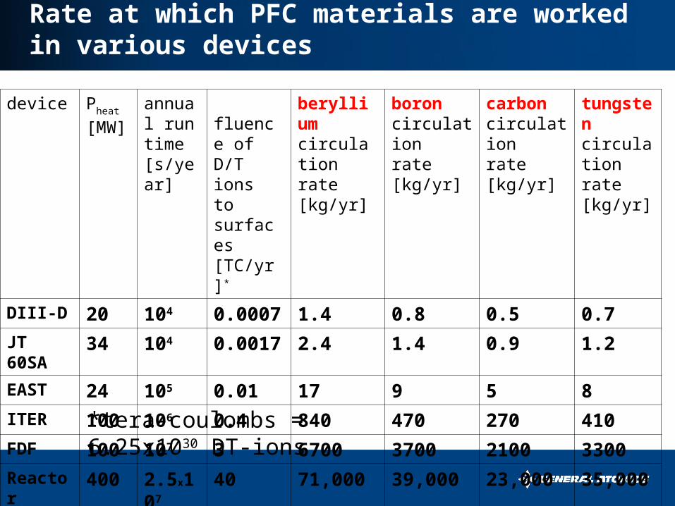
Rate at which PFC materials are worked in various devices
device Pheat
[MW]
annual run time [s/year]
fluence of D/T ions to surfaces [TC/yr]*
berylliumcirculation rate[kg/yr]
boroncirculation rate[kg/yr]
carboncirculation rate[kg/yr]
tungstencirculation rate[kg/yr]
DIII-D 20 104 0.0007 1.4 0.8 0.5 0.7
JT 60SA 34 104 0.0017 2.4 1.4 0.9 1.2
EAST 24 105 0.01 17 9 5 8
ITER 100 106 0.4 840 470 270 410
FDF 100 107 3 6700 3700 2100 3300
Reactor 400 2.5x10⁷ 40 71,000 39,000 23,000 35,000
*tera-coulombs = 6.25x1030 DT-ions

Net erosion in the divertor
• An FDF divertor plasma solution calculated by SOLPS (John Canik): ne ~ 1021m-3, T ~ 10 eV at outer strike point.
• Ionization mfp of physically sputtered Be, B, C ~ 0.3mm ~ ion larmor radius. Thus probability of prompt local redeposition ~ 1. Thus net erosion << gross erosion expected.
-5.0E+21
-2.5E+21
0.0E+00
2.5E+21
5.0E+21
2.2 2.25 2.3 2.35 2.4
R (m)
C/m
2 /s
DepositionErosion
Net Deposition DIVIMP code(David Elder)applied to SOLPSplasma solution, findscarbon net erosion << gross erosion.
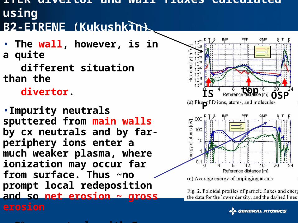
ITER divertor and wall fluxes calculated using B2-EIRENE (Kukushkin)• The wall, however, is in a quite different situation than the divertor.
•Impurity neutrals sputtered from main walls by cx neutrals and by far-periphery ions enter a much weaker plasma, where ionization may occur far from surface. Thus ~no prompt local redeposition and so net erosion ~ gross erosion
• D0 cx neutrals with E ~ 300 eV
ISP
OSPtop

Simple estimate for net wall erosion rates
• Assume physical sputtering for cx neutral tritons only. Yields for Ecx = 300 eV T (Eckstein 2002).
• Normal incidence yields doubled to account for surface roughness: for (Be, B, C, W), Ycx = (0.083, 0.056, 0.035, 0.0024).
• No sputtering included for D0, He0, low-Z neutral or self-neutral and no sputtering included for ion-wall interaction.
• Assumes Pcx = 0.05 Pheat (~Kukushkin for ITER), thus 0.025Pheat = Ecxφcx and gross erosion rate = Ycx φcx ~ net erosion rate for main wall.
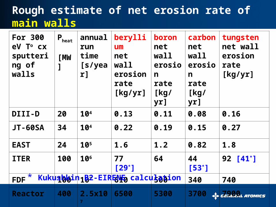
Rough estimate of net erosion rate of main wallsFor 300 eV To cx sputtering of walls
Pheat
[MW]
annual run time [s/year]
berylliumnet wall erosion rate[kg/yr]
boronnet wall erosionrate[kg/yr]
carbonnet wall erosionrate[kg/yr]
tungstennet wall erosion rate[kg/yr]
DIII-D 20 104 0.13 0.11 0.08 0.16
JT-60SA 34 104 0.22 0.19 0.15 0.27
EAST 24 105 1.6 1.2 0.82 1.8
ITER 100 106 77 [29*] 64 44 [53*] 92 [41*]
FDF 100 107 610 500 340 740
Reactor 400 2.5x10⁷ 6500 5300 3700 7900
* Kukushkin B2-EIRENE calculation
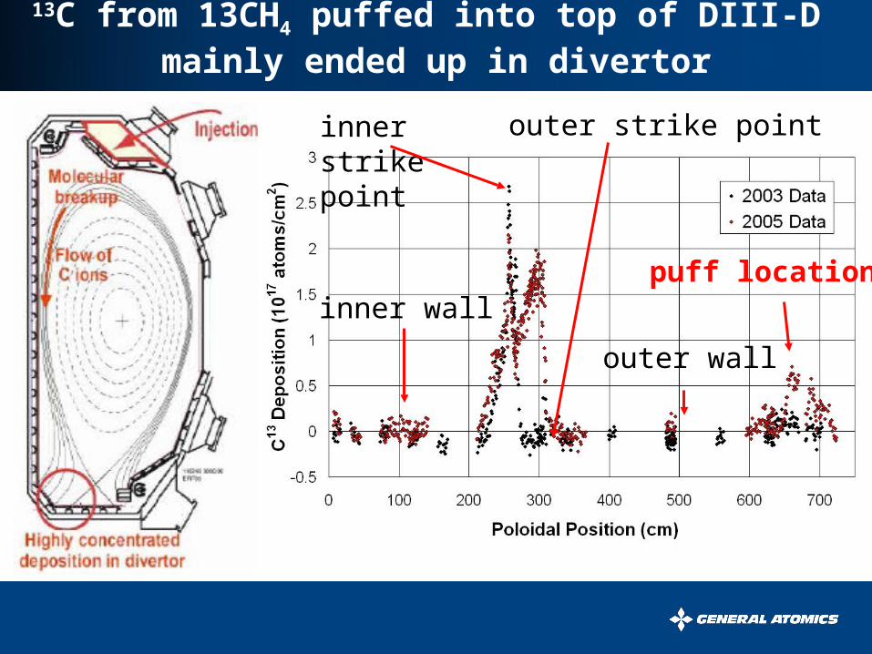
13C from 13CH4 puffed into top of DIII-D mainly ended up in divertor
puff location
inner strike point outer strike point
inner wall
outer wall
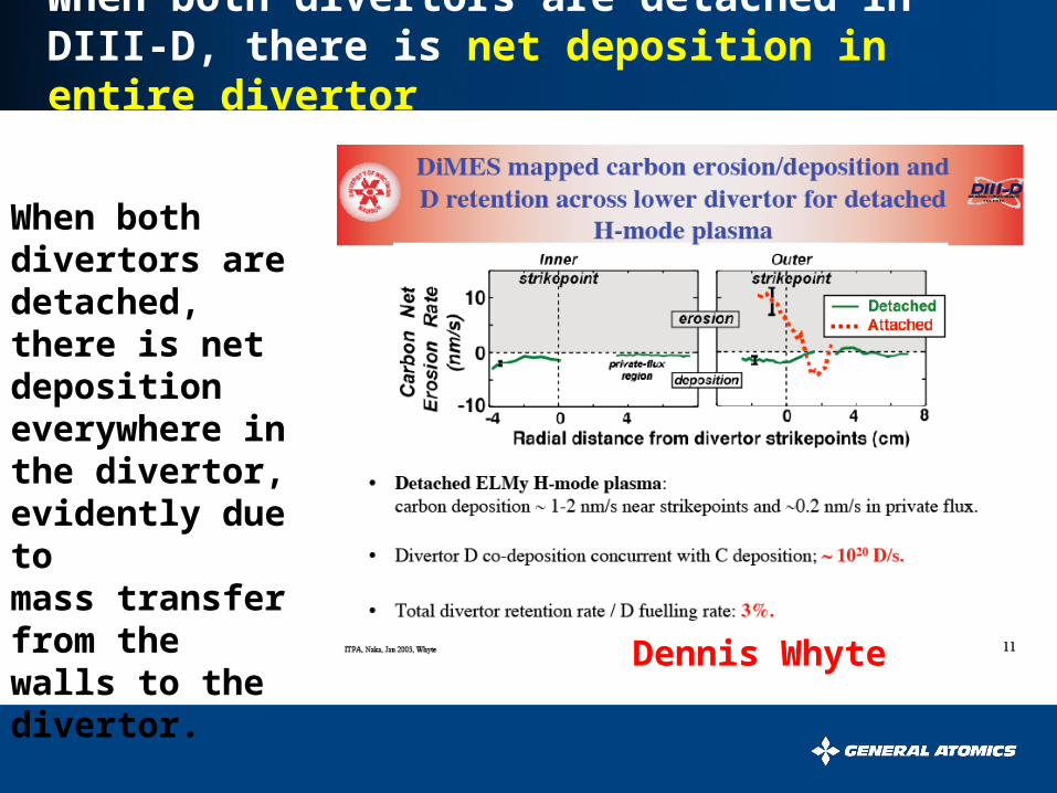
When both divertors are detached in DIII-D, there is net deposition in entire divertor
Dennis Whyte
When both divertors are detached, there is net deposition everywhere in the divertor, evidently due to mass transfer from the walls to the divertor.

Have we been worrying about the wrong problem?
• We have been greatly concerned about the problem of net erosion at the strike points.
• It may be, however, that for high power, high density plasmas, the entire divertor may be in net deposition due to mass transfer from the walls.
• Wall erosion itself may be tolerable if not too localized.
• The problem, however, will be how to clear the slag out of the divertor to avoid disrupting the plasma.
• All PFC materials may be ‘flow thru’ – or at least ‘flow in’.
Related Documents


