EDM Series Permanent magnet type synchronous motor INSTRUCTION MANUAL

Welcome message from author
This document is posted to help you gain knowledge. Please leave a comment to let me know what you think about it! Share it to your friends and learn new things together.
Transcript

EDM Series
Permanent magnet type synchronous motor
INSTRUCTION MANUAL

CONTENTS
I. Preparation for operation
1. Checking at arrival of motor
2. Storage
3. Installation
4. Electric wiring
1. Before powering
2. After powering
II. Trial operation and ordinary operation
III. Maintenance, checking
1. Daily checking
2. Periodical checking
3. Bearing and lubrication
4. Checking of accessories
5. Service life of main accessory parts
IV. Disassembly, Assembly
1. Procedures of disassembly and assembly
2. Structural drawing of motor
3. Replacement of bearing
V. Troubleshooting of motor
Please read surely the following precautions 1
1
1
1
2
5
7
7
7
8
8
8
8
10
10
11
11
13
15
16

!
!
!
!
Please read surely the following precautions
Introduction
We thank you for your adoption of Toyo Denki ED Motor (permanent magnet type synchronous motor). This Manual shows handling method of ED motor and precautions on use for customers having general knowl-edge on permanent magnet type synchronous motor. Before use, please read this Manual carefully until get-ting of enough knowledge on our ED motor and use it when it is in optimum condition.After reading, please keep this Manual close to the place where ED motor is used. In case of lease or trans-fer of ED motor, deliver this Manual together. When ED motor is used combining with machine or equipment, please arrange this Manual to be handed to the end user surely. If this Manual is lost or damaged, please or-der new one from us or our distributor. Meanwhile there is a possibility that we change parts of ED motor for the purpose of improvement of quality/performance or for safety. At such time, there may be a case that a part of content and illustration, etc. of this Manual does not conform to the original parts, for which please un-derstand. If there are any points which are unclear, please consult us or our distributor.
Safety precautions
Before works of installation, operation, maintenance, inspection, etc., please read carefully this Manual and the manual of Inverter equipment (ED64) and all of other attached documents surely for correct use. Please use ED motor after getting enough knowledge on it as well as information on safetyand all precau-tions. After reading, keep this Manual close to the place where operator can read it easily at anytime.In this Manual, ranking of safety precautions is classified to [Danger] and [Caution].
Danger
Danger
: In case of error in operation, dangerous situation may occur and it could result in death or serious injury.
Caution : In case of error in operation, dangerous situation may occur and it could result in medium or light injury, or damage to physical property only.
Since important contents are written in both safety precautions, make sure to observe them.
Even in case of above Caution , there is a possibility to lead to serious result depending on the situation.
(General)
・ Works of transportation, installation, piping, wiring, operation, maintenance, inspection must be carried out by qualified expert. Otherwise, that could result in electric shock, injury, fire, etc. ・ Avoid the work in state of hot-line. Be sure to work after breaking of power supply. Otherwise, that could
result in electric shock.・ Even in state that power supply is interrupted, voltage is generated at motor terminal while motor is run-
ning. Do not touch the motor until perfect stop of rotor and also avoid the work. Otherwise, that could result in electric shock and injury.・ In state that the power supply is interrupted, do not apply the motor to the usage which has a possibility of
being rotated faster than motor rating speed by the load. Otherwise, that could result in burning and fire. ・ Never use the motor in explosive atmosphere. Otherwise, that could result in injury, fire,
・ Surely ground the terminal for earthing. That could result in electric shock. ・ In case of use of motor fitting on the ceiling or on the wall, it may drop depending on the conditions.
Therefore, please obey to catalog and technical materials in regard to the details of range of use. Otherwise, that could result in injury.・ Operate the motor after confirmation that protection devices are firmly connected and they activate nor-
mally. Otherwise, that could result in injury and fire.
(Installation)

! Caution
! Danger
・ Do not operate the motor in state that the cover of terminal box is removed. After work, fit the cover of terminal box at the original position. Otherwise, that could result in electric shock.
(Piping, wiring) ・ Connection with power supply cable should be done in accordance with connection diagram or Instruc-
tion Manual. Erroneous wiring could result in electric shock and fire. ・ Do not bend or pull or put between something the power supply cable and lead wire of motor forcibly.
Otherwise, that could result in electric shock.
(Operation) ・ Never approach to or contact the rotating objects (shaft, etc.) during operation. Otherwise, that could result in injury by being caught. ・ When power is interrupted, turn off the power supply surely. Otherwise, that could result in injury when
power is supplied again.
(Maintenance and inspection) ・ Connection with power supply cable should be done in accordance with connection diagram
or Instruction Manual. Erroneous connection could result in electric shock and fire.
・ For installation place of motor, secure safe and adequate space for maintenance and inspection. Otherwise, trouble of electric shock and injury could occur.・ Do not use the motor under out of specifications of that motor. Otherwise, that could result in electric
shock, injury, breakage, etc. ・ Do not insert finger or object into the aperture of motor. Otherwise, that could result in electric shock,
injury, fire, etc. ・ Do not use damaged motor. Otherwise, that could result in injury, fire, etc. ・ In case of work at high place, prepare enough measures for prevention of drop.
Otherwise, trouble of injury by drop could occur.・ Since remodeling by user is out of range of our guarantee, we are not responsible for it.・ Do not put obstacles in front of motor name plate in order for operator to see it at any time.・ Do not remove the name plate.
(General)
(Transportation) ・ Since drop and falling down of the product during transportation is dangerous, please pay enough at-
tention for such work. As to motor, surely use designated position for hanging. After installation of mo-tor combined with machine, do not hang whole set of motor-machine at the position for hanging of mo-tor only. Before hanging, confirm mass of motor by name plate, packing case, outline drawing, catalog, etc. and do not hang the heavier motor than the rated load of hanger. Breakage of hanger and consequent drop as well as falling down could result in breakage of motor and injury.
(Unpacking)・ Unpack the case after confirmation of top and bottom. Otherwise, that could result in injury.・ Confirm whether reached product is just the ordered one. Installation of erroneously delivered product
could result in injury, breakage, etc.
・ Never place any inflammable objects around the motor. Otherwise, that could result in fire. ・ Do not place any objects which prevent ventilation, around the motor. Otherwise, that could result in
burn and fire by extraordinary overheat caused by prevention of cooling. ・ When motor is connected with machine, pay attention on centering, belt-setting, parallel degree of pul-
ley, etc. In case of series connection, pay attention on direct-connection accuracy. In case of belt con-nection, adjust tensile strength of belt correctly. Before operation, tighten clamp bolts of pulley and cou-pling firmly. Otherwise, trouble ofinjury and breakage of equipment caused by scattering of fragments could occur. ・ Avoiding touch with rotating part, mount the cover, etc. Otherwise, that could result in injury.
(Installation, adjustment)

! Caution
・ Repair and disassembly should be done by qualified expert. Otherwise, electric shock, injury, fire, etc. could occur.
・ In case of rotating of motor alone, remove temporarily fixed key to the main shaft. Otherwise, that could result in injury.・ Before connection of motor with machine, confirm its direction of rotation. Otherwise, that could result in
injury and breakage of equipment. ・ Never get on and dangle from motor. Otherwise, that could result in injury. ・ Do not touch with bare hand the keyway at shaft end of motor. Otherwise, that could result in injury.
(Piping, wiring) ・ At the time of measurement of insulation resistance, do not touch the terminals. Otherwise, that could
result in electric shock. ・ Carry out wiring work in accordance with [Electrical Facilities Technical Standards] and [Inner Wiring
Regulations]. Otherwise, that could result in fire.
(Operation)・ Since motor gets very hot during operation, do not touch it with hand or body. Otherwise, that could re-
sult in burn. ・ When error occurred, stop operation immediately. Otherwise, that could result in electric shock, injury,
fire, etc.
(Maintenance, inspection)・ At the time of measurement of insulation resistance, do not touch the terminal. Otherwise, that could re-
sult in electric shock. ・ At the time of injection/discharge of grease to/from bearing, do not touch rotating object. Otherwise,
that could result in injury.・ Since frame of motor gets very hot, pay attention at the time of maintenance and inspection in order to
avoid burn.
(Repair, disassembly)
EDM Series ED motor is the most suitably designed motor for Inverter drive by Toyo Denki having high level technology in rotary machine and control equipment.
Explanation of type name
E D M 1 9 1 1 V-C 1 A A -H 0 1
Main mechanical variation on external form
Details of protection system or cooling system
Electrical specifications
Cooling system
Installation structure of motor
Frame spigot diameter
Series number

1
I. Preparation for operation 1. Checking at arrival of motorWhen the ordered motor arrived, please check paying attention to the following points.
(1) Check the motor with our invoice separately sent.
(2) Check the motor for damage, rusting, dropping of accessories, etc.
(3) There is a case that the rotor of motor is fixed in order to prevent the bearing from being damaged during
transportation. Check the rotor and remove it.
(4) Rotate the shaft end manually to confirm smooth rotation.
(5) Check the motor output, voltage, current, frequency, rotation speed, etc. shown on the name plate.
Connector for pulse oscillator
Frame
Main terminal box
Shaft
Bracket
Fan cover
Photo. of external appearance of motor
Auxiliary terminal box (for cooling fan)
2. Storage
(1) In case that the motor is stored for 3 months or longer till the initial operation after receiving it or its opera-
tion is stopped for 3 months or longer, take the following steps.
1) Storage
2) Exposed machined
3) Rotation of shaft
4) Bearing and lubrication
・ Shielded bearing
surface
: The motor should be placed in the same posture with correct installation
state, covered with waterproof sheet, and be kept at a dry place.
: Apply rust-preventive agent every 6 months. If motor is export-packed, un-
pack it after elapse of one year and apply the rust-preventive agent.
: Operate the motor for a few minutes every 3 months (and beforelong stor-
age) or rotate the saft manually about 10 times. If motor is export-packed,
follow item 4) below.
: After storage of motor for 2 years or longer, pay attentionwhether abnormal
sound is heard from bearing during trial operation. If it is heard, replace the
bearing.
: Replenish the quantity shown on the name plate, rotating the shaft manually or
operating the motor every one year. (If the motor is export-packed, unpack it
temporarily and replenish the grease.)
・ Grease replenish-ment type

2
: In case that the motor is not used for a long time, measure the insulation resis-tance of the winding every 6 months and before starting of operation. If resis-tance is lower than 1 MΩ at ordinary temperature and its cause is not the mois-ture adsorption in the terminal box, dry the winding.
5) Insulation resistance of winding
When the motor is stopped for 1 day or longer, energize the heater. 6) Space heater : (when provided)
7) Surface painting : Re-paint every 2 years, as the need arises.
8) Drain plug (when provided)
: Open the drain plug periodically (at least every 6 months) and before starting of operation.
3. Installation3.1 Installation place
(1) Install the motor at a well-ventilated place and arrange not to return the coming out heat from the motor, to the intake side by circulation. At a place where the ambient temperature is high or when the motor is influ-enced by heat radiation/conduction, take measures such as heat insulation, reduction of load, etc.
(2) Distance between the inlet of cooling fan of the motor and the wall should be 20cm or more for EDM17 - EDM31 and 30cm or more for EDM35~ EDM54.
(3) Place with less humidity. (4) Place with less dust. If dust is accumulated on the fins of frame, cooling effect wil be reduced causing
overheating. Therefore, periodical cleaning should be done in case of dusty place. (5) Place where motor is not influenced by noxious gas and acid/alkaline chemicals, etc. When motor is used
at a place where flammable gas exists, re-check whether selected explosionproof structure conforms to the regulations of Ministry of International Trade & Industry and the Ministry of Labour.
(6) Place where such works as disassembly, inspection, cleaning and maintenance can be carried out easily. (7) Install the motor on a strong foundation and rigid common base so that external vibration will not be con-
ducted to the motor. If vibration during operation is large, bearing life will be shortened and it will cause the vibration fatigue failure of fan, rotor, etc.
(8) Place with less fluctuation of supply voltage and less voltage drop.
3.2 Connection with counterpart machine
(1) Foundation work In order to minimize the vibration and misalignment during operation, strong foundation is required. If foun-dation is incomplete, machine will vibrate and bearing life will be shortened, to which please pay attention. The most ideal foundation in order to prevent generation of vibration is a strong concrete foundation but if such concrete foundation cannot be made because of counterpart machine and relation with the place, in-stall the motor on the steel frame with bolts firmly arranging that the motor shaft exactly level (or perpe-ndicular for a vertical motor) surely. For the base, ac-hieve the level degree of 0.2/1000mm or less accur-ately. Also, clean the surfaces of concrete foundat-ion / steel frame and of the leg of motor for ideal installation.
(2) In case of flexible coupling1) Mark the matchmarks on the outer surface of cou-
pling. 2) In order to rotate the couplings together, connect
couplings of the counterpart machine and of the motor by one bolt.
Matchmark
Stretch
h : Parallelism
g : Eccentricity
Fig. 1

Contact angle (θ) 140° 150° 160° 170° 180°
Correction factor (Kθ ) 0.89 0.92 0.95 0.98 1
3) Fix a dial gauge firmly to outer surface of one coupling. (Fig. 1)4) Move the matchmark of the coupling to the top and measure the dimension-g by clearance gauge and di-
mension-h by dial gauge.5) Rotate the coupling and carry out same measurement as above item 4) at every 90 of quadrant positions. 6) Adjust using shim plates so that the difference between maximum and minimum of the measured values
will be 0.03mm for both g and h. Every time the measurement for adjustment is carried out, tighten the in-stallation part with bolt sufficiently. When dial gauge cannot be fitted for a small motor, apply the stretch to the outer surface of one coupling and measure the clearance between stretch and the other coupling.
(3) In case of belt drive
Set the counterpart machine shaft and motor shaft accurately parallel and apply the belt in such a way that both pulley cen-ters coincide each other. The belt is apt to be stretched too much however, excessive stretching will damage the bearing and cause unexpected ac-cidents such as breakage of motor shaft, etc., to which please pay attention.
1) Belt stretching methodStep 1 : Firstly, find the belt span (Ls). Belt span is the length
of the portion of belt between contact points with both pulleys.
Step 2 : Apply the force (Pk), which is required for deflection (δ), at the center of the belt span. This required force for deflection (δ) should be calculated by the formula 5 shown below and it should be within the range of Pk1 - Pk2.
Step 3 : Stretch the belt in such a way that the deflection(δ), when the force is applied, will be the value found by the following formula.
δ= 0.016・Ls
Mot
or
Cou
nter
part
mac
hine
Motor side pulley
Fig. 2 Belt stretching method
(Belt cont-act angle) θ
2) Calculation formula
Step 1 : How to find belt contact angle (small pulley side) ... Formula 1
Formula 1
Formula 2
Step 2 : How to find initial tension (Fo) ...................................Formula 2
Fo : Initial tension (N)
Kθ : Contact angle correction factorPd : Design power (kW)
Z : Number of belt v : Belt speed (m/sec) m : Mass/unit of belt (kg/m)
Pd = PN x (Ko+K i ) PN : Load power (motor output, in general) (1kW)
K o : Load correction factor (1.0 ~ 1.5)
K i : Idler correction factor (0 ~ 0.2)
Note) Determine K o, K i depending on the machine to be used and operation time,referring JIS Standard or catalog, etc. of belt maker.
θ=180° - 2sin-12C
d2-d1
Fo = 0.9 500 ( ) Kθ
Kθ 2.5- Z・v Pd + m・v2{ }
3

Step 3 : How to find span (Ls) ................................. Formula 3
Formula 3
4 Ls = C2 -
(d2-d1) Ls : Span (mm)
C : Distance between shafts (mm)
d2 : Large pulley nominal diameter (mm)
d1 : Small pulley nominal diameter (mm)
Step 4 : How to find deflection (δ) ........................... Formula 4
Formula 4 δ= 0.016・ Ls δ : Deflection (mm) Step 5 : How to find necessary force (Pk1, Pk2) for deflection (δ) ... Formula 5
Formula 5Pk1 (min. value) = Fo + Y
16 Pk1 : Necessary force (min. value) (N)
Pk2 : Necessary force (max. value) (N) for deflection (δ)
for deflection (δ) Pk2 (max. value) = 1.25 x Fo + Y
16
Kind of belt Y(N) m(kg/m)
A type
B type
C type
D type
3Vtype
5Vtype
8Vtype
Standard V belt
Narrow V belt
Type of motor
Permissible shaft load F(N)
Q (mm)
Q'(mm)
15
20
30
60
20
39
98
0.12
0.20
0.36
0.66
0.08
0.20
0.50
EDM1711 EDM1721 EDM19 EDM22 EDM27 EDM31
1600 2240 2930 5360 9080 12100
80 110 110 110 140 140
31.5 41 50.5 68 93.5 106
EDM35
18800
170
91.3
EDM43
24200
175
108.8
[Note] Type of motor, for which the belt can be applied, is till EDM4321V EDM4331V and EDM54 are for direct connection only.
Belt speed should be : -
Standard V belt (A, B, C, D types) ..... 30m/sec or less
Narrow V belt (3V, 5V, 8V types) ....... 40m/sec or less
This matter should be taken into consideration when pulley
diameter is determined. The belt tension differs depending on the kind of belt however, the radial load imposed on the motor shaft should be less than the values in the above table.
(4) Mounting of coupling and belt pulley
Coupling and belt pulley should be mounted carefully not to damage the motor bearing. Lightly press-fit them by wooden or plastic hammer. In case of heating, heat them untill about 100 C uniformly. In case of press-fitting, remove the rust preventive agent on the shaft end by petroleum solvent or alkali solvent, and apply molybdenum disulfide.
[Caution]
In case that the pulse oscillator for speed detection is provided on the shaft end of non-transmission side, be careful not to give impact to it when coupling and belt pulley are inserted since it may be damaged by such impact. (See Structural Drawings Fig. 9 - Fig. 11)
4
2
(5) In case of flange type motorFlange engagement surface is accurately machined. If contaminant, paint, rust, etc.are found there, remove them surely.
4. Electric Wiring
4.1 Terminal box
There are main terminal box for motor main body terminals and thermistor, and auxiliary terminal box for elec-tric fan. Connect external wirings correctly and firmly. Connection with pulse oscillator of motor side is con-nector-connection.
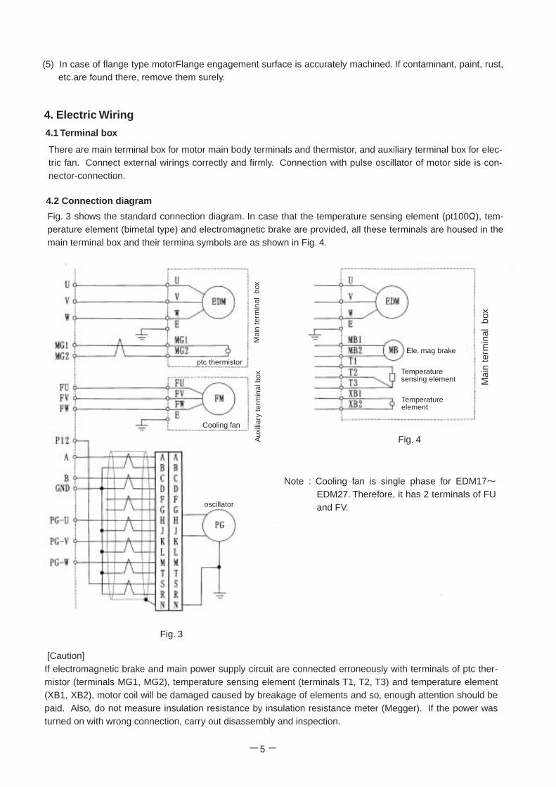
4.2 Connection diagram
Fig. 3 shows the standard connection diagram. In case that the temperature sensing element (pt100Ω), tem-perature element (bimetal type) and electromagnetic brake are provided, all these terminals are housed in the main terminal box and their termina symbols are as shown in Fig. 4.
Mai
n te
rmin
al b
ox
Mai
n te
rmin
al b
ox
ptc thermistor
Aux
iliar
y te
rmin
al b
ox
Cooling fan
Ele. mag brake
Temperature sensing element
Temperature element
Fig. 4
Note : Cooling fan is single phase for EDM17~EDM27. Therefore, it has 2 terminals of FU and FV. oscillator
[Caution] If electromagnetic brake and main power supply circuit are connected erroneously with terminals of ptc ther-mistor (terminals MG1, MG2), temperature sensing element (terminals T1, T2, T3) and temperature element (XB1, XB2), motor coil will be damaged caused by breakage of elements and so, enough attention should be paid. Also, do not measure insulation resistance by insulation resistance meter (Megger). If the power was turned on with wrong connection, carry out disassembly and inspection.
Fig. 3
5

6
4.3 Direction of rotation
(1) Direction of rotation must be correct. (2) Direction of rotation of the motor is expressed as seen from the shaft end of drive side. Standard direction
of rotation of the motor is counterclockwise (CCW) in case that the phase sequence of power supply side is R, S, T and when these phases are connected with the motor terminal symbols U, V, W.
4.4 Checking of wiring
(1) Terminals must be connected correctly in accordance with connection diagrams (Fig. 3, Fig. 4). Due atten-tion should be paid to the following points. 1) For the signal cable between pulse oscillator (PG) and controller, the twisted pair, shielded cable
should be used for protection against noise. The length should be 100m or less. Also, connection with pulse oscillator of motor side is connector connection and therefore, undermentioned straight plug and cable clamp are needed in addition to the cable.
Recommendable cable ...Twisted pair, shielded cable ... CO-SPEV-SB(A)7P-0.5SQ (product of Hitachi Elec. Wire Co.) Straight plug ... MS3106B-20-29S (product of Nihon Koukuh Densi Co. or equivalent) Cable clamp ... MS3057-12A (product of Nihon Kouhuh Densi Co. or equivalent) 2) As to the shielded cable (N), ground that of the motor side only. 3) Never carry out the measurement of insulation resistance (Megger test) of pulse oscillator. Use tester
for this measurement.4) For the wiring cable of ptc thermistor, use twisted pair cable. 5) The earthing terminal (E mark terminal) provided in the main terminal box must be grounded. The
earthing terminal (E mark terminal) is provided also in the auxiliary terminal box for cooling fan. please ground it surely.
(2) Checking of the direction of rotation of electric fan
After finish of wiring work, check that the electric fan for cooling rotates to the correct direction, before start-ing of normal operation. (direction of rotation and cooling air flow are indicated on the fan cover.)
4.5 Detailed drawings of terminal boxes
Main terminal box (Fig. 5) and cooling fan terminal box (Fig. 6) are terminal block type. However, for the mo-tors EDM43 and EDM54, main terminal box is lug type.
ptc thermistor lead wire primary lead wire
earth terminal symbol
earth terminal symbol
In case of single phase, terminal symbols are FU and FV.
Fig. 5 Detailed drawing of main terminal box
Fig. 6 Detailed drawing of cooling fan terminal box

II. Trial operation and ordinary operation 1. Before powering
All of your purchased motors from us passed severe tests at our factory however, they may have a possibili-ty of being damaged during transportation or affected by long storage, and so carry out following checking, confirmation before starting of operation.
(1) Precautions for working before trial operation1) Check that the shaft fixer and cover for the time of storage were removed. 2) Check whether electric wiring was correctly carried out and terminal box cover was fitted.3) Check whether loose tightening bolts are found at individual part. 4) Check whether the motor is well ventilated.5) Check whether rotating part contacts fixed part when the shaft is rotated manually.6) Measurement of insulation resistance of stator coil to earth. Disconnect the motor main circuit at the ter-
minal block of the controller side and measure insulation resistance using 500V Megger between motor terminal and earth. Although it is difficult to generally indicate the insulation resistance value, criterion is 1MΩ or over.
7) Check whether earth terminals of individual part are completely connected.
(2) Lubrication
For the grease lubrication type motors, the bearing portion is filled with grease before shipment. However, if they are not used for more than 6 months after arrival at the site, the grease must be replenished soon after starting of operation. This work is not necessary in case of use of sealed-grease type bearing.
(3) Others
Check the status of direct connection and belt tension as well as tightening of bolts and nuts of the individ-ual part.
2. After powering
(1) In the initial operation, the motor should be operated with no load independently at as low as possible speed in order to confirm no abnormality. After that, the motor should be connected with the counterpart machine.
(2) After starting of operation, check the following points.
1) Whether direction of rotation (standard direction of rotation is clockwise as seen from non-load side) is correct.
2) Whether abnormal sound is heard from the bearing part. 3) Whether abnormal sound is heard from inside of the motor. 4) Whether burning smell of insulator, etc. is sensed. 5) Whether abnormal vibration is sensed. If the total amplitude exceeds 30μm, investigate the cause and
take necessary measures. 6) Whether supply voltage and phase current are balanced. 7) Whether starting time is abnormally long.
Checking the above points, proceed independent operation, no-load operation, full-load operation sequentially and if all of them are normal, start full scale operation.
7

III Maintenance, checking In order to prevent accidents in operation of the machine, daily monitoring or checking is required.
1. Daily checking
By touching and hearing, check the vibration and sound at the time of starting and during opera-tion of the machine and confirm that there is no abnormality. User is recommended to put the status of operation on record. Records of daily checking :-
(1) Date, time of measurement. Weather of the day of measurement (2) Voltage, load current, frequency, rotation speed (3) Ambient temperature(4) Temperature of stator winding or frame (5) Temperature and sound of bearing (6) Abnormal vibration (7) Cooling air condition of cooling fan
2. Periodical checking (1) Measurement of insulation resistance (2) Checking of bearing related items(3) Condition of ventilation(4) Measurement of vibration (5) Looseness of tightening nuts (6) Condition of direct connection of coupling and belt tension(7) Cleaning of individual part(8) Checking of power supply condition (9) Checking of pulse oscillator, cooling fan
Checking items are as shown above. The insulation resistance should be measured every 6 months and the other items should be checked once a year.To measure and monitor the machine vibration periodically is very important for the maintenance/checking of the machine. If vibration is large, it affects the bearing, winding and condition of direct-connection badly and therefore, investigate the cause and repair the faulty part.
3. Bearing and lubrication
3.1 Shielded bearing
For the motors of EDM17~EDM22 and EDM27~EDM35 (non-load side), shielded type ZZ (non-contact type sealed grease) bearing is used. Generally, the bearing should be replaced at the time of periodical checking. Until that time, grease maintenance is not required.
8

3.3 Use of grease of different type for the grease replenish type bearing
(1) Avoid mixed use of different brands of grease. Depending on the combination, properties of grease may greatly change.
(2) In case that the user is compelled to use a grease of different brand from the grease of the time of deliv-ery, the following method should be taken.1) Open the grease drain port and inject new grease while scraping out the old grease, during operation
or by manual rotation of the shaft.2) Repeat this work until the new grease comes out of the grease drain port.
(3) When the grease is injected, bearing temperature may rise. In such a case, stop the the injection until low-ering of bearing temperature. After that, repeat the injection of the grease .
3.2 Grease replenish type bearing
For the motors of EDM43 or over, kind, quantity and interval of replenishing of grease are indicated on the name plate.
(1) Replenish the grease during operation at every replenishment interval (operation time) indicated on the name plate. In case that the net operation time is short due to short-time or repetitive operation, grease should be replenished in such a way that the elapsed time including stoppage will not become twice or more of the interval indicated on the name plate, or at least every 6 months - one year.
(2) When grease is replenished, be sure to rotate (300 r/min or more) the motor, clean the grease nipple, and replenish necessary quantity by grease gun through the nipple. At every time of grease replenishment, scrape out old grease from grease drain port.
(3) When the grease is replenished, bearing sound will become temporarily louder a little or the bearing tem-perature will rise 5°C ~ 10°C higher than the normal one, because of excess grease, but it will return to normal one in several hours to 1 day.
(4) Table 1 shows approximate values of grease replenishment quantity and replenishing timing.
At the forwarding from our factory, bearings are filled with Mul-temp SRL (of Kyodo Yushi Co.) unless otherwise specified, (or grease of the brand specified by user). For replenishment of grease, we recommend this Multemp SRL. If grease of this brand is not obtainable, the equivalent greases shown in the table below can be used.
9
Table 1 Grease replenishment quantity
Type of motor
Load side bearing No. Replenishment quantity
(g)
Replenishing timing (cumulativeoperating time) (Hr) at specified speed Non-load side
bearing No 1750 r/min 1450 r/min 1150 r/min
EDM27
EDM31
EDM35
EDM43
EDM54
NU313 6312ZZ NU3166315ZZ NU320
6315ZZ
NU324
6318 6324
6318
33 3400 4200 5400 -- -- -- --
47 3000 3700 4800 -- -- -- --
72 2600 3200 4200 -- -- -- --
102 2300 2900 3700
24 2300 2900 3700 102 4700 5800 7600
48 4700 5800 7600
Maker name Brand of greaseKyodo Yushi Multemp SRL Nippon Oil Multi Knock Wide 2MOBIL Mobil Temp SHC100SHELL Variant M2ESSO Templex N2

3.4 Sound of bearing (Grease replenish type)
Sound of bearing during operation is classified as follows.
(1) Normal sound
The normal sound is continuous one. The race sound, jarring sound and retainer sound are considered as normal. The jarring sound may be misunderstood as an abnormal noise but it does not mean the abnormality of bearing. The jarring sound dies away temporarily when the grease is injected in general.The jarring sound may be generated in the following cases.
1) In case of bearing clearance C3 or C4 for high speed machine2) In case of cylindrical roller bearing3) In case of operation in winter of low ambient temperature and of the beginning of operation after long stoppage.
(2) Abnormal sound
1) Flaw noise or dust noise, etc. are abnormal sound.2) Abnormal sound is discontinuous and in some cases it accompanies vibration. 3) When abnormal noise sounds, inject new grease and observe change in sound and temperature for a while. If
abnormal noise does not stop, the bearing should be replaced.
4. Checking of accessories
For checking of accessories of electromagnetic brake, speed reducer, etc., see the Instruction of Manual for accessories of the separate volume.
5. Service life of main accessory parts
Some parts of motor have their service life limit. It differs depending on the serivce environment/conditions and therefore, carry out checking or replacement of parts making the undermentioned service life limit as a criterion.
5.1 As to motor related parts(1) Motor bearing (at ambient temperature of 40°C or lower and speed of 1800 r/min)
1) Grease replenish type bearing ..... About 50,000 hours2) Shielded bearing .................. About 32,000~ 47,000 hours
・Sealed grease is of Multemp SRL of Kyodo Yushi, or equivalent. ・Life of shielded bearing is determined depending on the life of sealed grease. Life of sealed grease
is affected by the ambient temperature and is shortened about 1/1.5 every time the ambient temper-ature rises 10°C from 40°C.
(2) Fan motor .......... About 3~4 years (at ambient temperature of 40°C or lower) (3) Pulse oscillator ... About 4~5 years (at ambient temperature of 40°C or lower and speed of 1800 r/min)(The shielded bearings of fan motor and pulse generator will reach the limit of their service life.This limit dif-fers depending on the ambient temperature.
5.2 Helical speed reducer (at ambient temperature of 40°C)
(1) Each bearing ....... About 25,000 hours
(2) Oil seal .................About 10,000~15,000 hours as a criterion (Life differs greatly depending on the envir-onmental conditions for use.)
(3) Replacement cycle of lubrication oil First time : 500~1,000 hours after starting of operation. Subsequently : Every 2,500 hours.
10

IV Disassembly, AssemblyThis motor incorporates permanent magnet in its rotor. Owing to this composition, pulling out of the rotor from the stator is quite difficult. Therefore, do not pull out the rotor from the stator at the time of disassembly/as-sembly of motor, such a case of replacement, etc. of bearing. Replacement of bearing can be carried out keeping the rotor inserted in the stator. Also, at the time of disassembly/assembly, do not proceed the work at load side and non-load side simultaneously. Surely after completion of work of one side, start the work of the other side (As to the order of work, starting from any of both side is available). Since magnetism of the mag-net of rotor acts to outside a little during the works of disassembly/assembly of motor, do not make Watch, Magnetic Card, etc. approach to the motor.
1. Disassembly/assembly procedures (See Fig. 7 below and structural sectioned drawings (Fig. 8~Fig. 10)
(1) Break the power supply. (2) Remove the connection with the load. (3) Remove all the external wirings connected with the terminals in the terminal box. (4) Remove the connection part of pulse oscillator output cable connector at upper part of fan cover.
1.1 Non-load side
(1) Remove pulse oscillator output cable connector from fan cover.(2) Remove fitting bolts of fan cover and remove fan cover. At this time, cooling fan installed at fan cover is
also removed in combined state with fan cover.(3) Remove fitting screws of pulse oscillator cover and remove pulse oscillator cover. At this time, pulse oscilla-
tor output cable is led from lower part of pulse oscillator and therefore, pay attention not to be pulled this cable.
(4) Remove screws, which fix the plate spring of pulse oscillator stator to the mount of
Pulse oscillator output cable connector
Fan cover
Pulse oscillator mount
Pulse oscillator cover
Pulse oscillator
Non-load side bracket
Frame
Inner cover of non-load side bearing
Non-load side bearing
C-type snap ring
Motor shaft Plate spring
Set screw (M4 - 2 posi-tions) (applied with screw lock for whirl-stop)
position cross section of motor shaft (See [Note] of P.12 )
Position of plate spring fitting screw
Pulse oscillator output cable Detail of A-A
Fig. 7 Detailed drawing of non-load side pulse oscillator and bearing part
11

1.2 Load side
(1) Remove the bearing outer cover of load side. (For EDM17~EDM22, this cover is unified unit with bracket.) (2) Pull out the slinger of bearing outer side of load side from the shaft. Slinger is fixed to the shaft by screw at one
position. ( Motors, to which the outer slinger is attached, are EDM31~EDM54) (3) Remove the bracket of load side. When it is removed, mark the matchmarks. As to the motors EDM27~
EDM43 using roller bearing, pay attention since bearing outer ring also is pulled out together. (4) Pull out the bearing from the shaft by puller. (As to the detail of replacement work of bearing, refer to item IV-3.)(5) After completion of disassembly, wash off the grease on the bearing and bearing cover, etc. by clean washing
oil. (This work is unnecessary for the shielded bearing.) (6) Fill the cleaned bearing or replaced bearing with grease, turning the outer ring.
Fill the bearing cover with grease of about 1/2 to 1/3 of the capacity. (This work is unnecessary for the shielded bearing.)
(7) Carry out assembly work under reversed procedure of disassembly procedure. Alien matchmarks marked at the time of disassembly and tighten the bolts of diagonal positions alternately in order to avoid uneven tight-ening.
(8) After assembling, rotate the shaft manually to confirm smooth rotation.
[Note]1) Giving the impact to the pulse oscillator will cause trouble. Never hit it with hammer, etc. Since clearance fit is
adopted for engaging of pulse oscillator rotor and shaft, they can be pulled out manually. 2) Even for the cases of removing and re-mounting of pulse oscillator at the times of replacement, etc. of bearing or
pulse oscillator, setscrew position for fixing the pulse oscillator rotor is determined to make that the magnetic pole position detection of the rotor of motor is same. As shown in Detail of A-A Cross Section of Fig. 7 of Page 11, when one of 2 positions of setscrew M4 is coincided with flat cut position of motor shaft (one position of mo-tor shaft, where setscrew contacts, is flat surface), mount the other setscrew arranging that it surely comes to the position turned 90°to counterclockwise seen from the non-load side shaft end (position where motor shaft is not cut flatly).As to motors EDM31~EDM54, the part where pulse oscillator rotor is inserted, is an insulated short shaft. When this insulated short shaft is removed from motor shaft, be sure to mark the matchmarks. (After mounting, confirm that the direction of keyway position of output shaft of motor shaft and flat cut position of insulated short shaft is same.)
12
(5) Loosen about 3 turns the 2 setscrews fixing the pulse oscillator rotor to the motor shaft and remove pulse os-cillator. (Do not take off the setscrews.) In case that the electromagnetic brake is provided, remove it.
(6) Remove the fixing screws of the pulse oscillator mount, and remove that mount. When the mount is removed, mark the matchmarks. (For EDM22~EDM54, it is unnecessary to remove the pulse oscillator mount.)
(7) Remove the bearing outer cover of non-load side (since the cover of EDM17~EDM35 is unified type with bracket, remove the fixing bolts of the bearing inner cover). When that outer cover is removed, mark the matchmarks.
(8) Remove the bracket of non-load side. When it is removed, mark the matchmarks. (9) Remove the insulated short shaft (this shaft is attached to EDM31~EDM54 and not attached to EDM17~
EDM27, of which shaft is unified type with motor shaft.) of non-load side shaft end. When that short shaft is removed, mark the matchmarks.
(10) Remove the C-type snap ring by the pliers. (EDM17~EDM35) Remove the bearing nut, bearing washer and outer slinger. (EDM43, EDM54)
(11) Pull out the bearing from shaft by the puller. (As to the details of replacement work of bearing, refer to item IV-3.)(12) After completion of replacement work of bearing, carry out assembly work under reversed procedure of disas-
sembly. Alien the matchmarks marked at the time of disassembly and tighten the bolts of diagonal positions alternately in order to avoid uneven tightening.
(13) After assembling, rotate the shaft manually to confirm smooth rotation.

2. Structural drawing of motor
Fig. 8 Structural sectioned drawing of EDM17~EDM22
No. Name 1 Shaft 2 Load side double shiel-
ded ball bearing 3 Load side bracket 4 Stator coil 5 Rotor 6 Permanent magnet 7 Stator 8 Frame 9 Foot 10 Main terminal box 11 Non-load side bearing in-
ner cover 12 Non-load side double
shielded ball bearing13 Non-load side bracket14 Electric cooling fan15 Terminal box for electric
cooling fan16 Pulse oscillator 17 Pulse oscillator output
cable connector 18 Fan cover
No. Name 1 Shaft 2 Load side bearing outer
cover 3 Load side roller bearing4 Load side bearing inner
cover 5 Load side bracket6 Stator coil7 Rotor8 Permanent magnet9 Stator10 Frame 11 Foot 12 Main terminal box 13 Non-load side bearing in-
ner cover 14 Non-load side double
shielded ball bearing 15 Non-load side bracket16 Electric cooling fan 17 Terminal box for electric
cooling fan 18 Pulse oscillator 19 Pulse oscillator output
cable connector 20 Fan cover
Fig. 9 Structural sectioned drawing of EDM27~EDM35
13
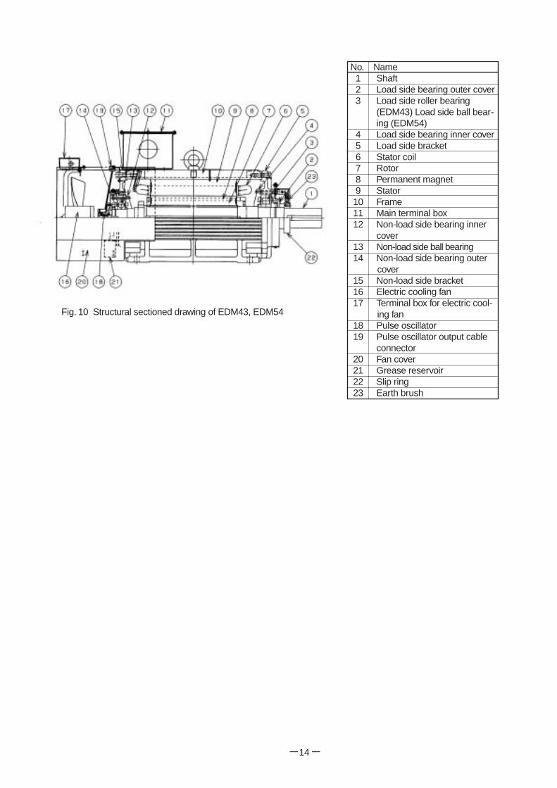
No. Name 1 Shaft2 Load side bearing outer cover3 Load side roller bearing
(EDM43) Load side ball bear-ing (EDM54)
4 Load side bearing inner cover5 Load side bracket6 Stator coil7 Rotor8 Permanent magnet9 Stator10 Frame11 Main terminal box12 Non-load side bearing inner
cover13 Non-load side ball bearing 14 Non-load side bearing outer
cover15 Non-load side bracket16 Electric cooling fan17 Terminal box for electric cool-
ing fan18 Pulse oscillator19 Pulse oscillator output cable
connector20 Fan cover21 Grease reservoir22 Slip ring 23 Earth brush
Fig. 10 Structural sectioned drawing of EDM43, EDM54
14

Bearing inner cover
Inside slinger
Stud
Outside slinger
Roller bearing
Fig. 14
15
3.2 Mounting of bearing
(1) New bearings packed and stored should not be unpacked until they are used. (2) Thinly apply the grease to the inner surface of the housing, in which the bearing is mounted.(3) Before insertion of bearing, mount bearing inner cover (if provided) and inside slinger (if provided) to the
shaft. Similar to the bearing, make shrink fit of inside slinger to the shaft, referring item (4).(4) Heat the ball bearing or roller bearing inner ring in oil, thermostatic oven or by induction heater to about 80
C and insert it onto the shaft. Be careful not to over- heat it. For the shielded bearing, method of heating in oil should not be applied.
(5) Filling quantity of grease for grease-replenish type In order to fill the grease in the clearance of the bearing itself and further in the grease injection passage, inject the replenishment quantity indicated on the name plate after assembling of rotary machine.
[Note] After replacement of bearings of non-load side and load side (EDM27~EDM54), fit the stud (2 pcs.) to the holes for the bracket fitting bolt of bearing inner cover, before mounting of the bracket. By this work, bearing cover fitting bolt can be fitted easily. (See Fig. 14)
Bearing inner cover
Inside slinger
Roller bearing inner ring
Puller
Fig. 13 Removal of roller bearing inner ring
3. Replacement of bearing
3.1 Removal of roller bearing inner ring and ball bearing (1) The pliers is used for removing the C-type snap ring and
the puller for removing the slinger and bearing. (2) For the roller bearing, apply a brass or copper plate to the
outer ring and alternately hit it at diagonal positions on thecircumference with a hammer to remove it from the shield. (Fig. 11)
(3) Pull out the ball bearing (Fig. 12) and roller bearing inner ring (Fig. 13) with a puller. In case of grease-replenish type structure, pull out above parts together with bearing inner cover and inside slinger. Bearing outer ring Roller bearing Bearing inner cover inner ring Puller Inside slinger.
Hammer
Roller Retainer
Housing
Plate (brass or copper)
Roller bearing outer ring
Fig. 11 Removal of roller bearing outer ring
Bearing outer ring
Fig. 12 Removal of ball bearing
Puller
Bearing inner ring

16
V. Troubleshoofing of Motor
Table 2 Motor Troubleshooting
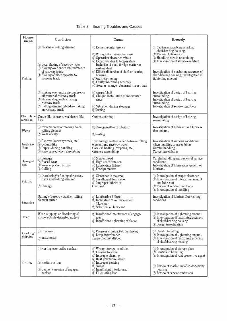
If the daily checking and periodical checking in �. Maintenance/Checking are correctly done, the motor
satisfactorily works. Table 2 shows "Motor Troubleshooting" and Table 3 "Bearing Troubles and Causes". They
should be referred to for daily maintenance/checking.
17
Table 3 Bearing Troubles and Causes

ITE048A-E04-8 500K
Related Documents