2.4 SERVICE MANUAL Manual Part No. 0G2832 G2 GAS ENGINE

Perkins Gas Eng. 2.4-SM
Dec 13, 2015
Service Manual
Welcome message from author
This document is posted to help you gain knowledge. Please leave a comment to let me know what you think about it! Share it to your friends and learn new things together.
Transcript

2.4SERVICEMANUAL
Manual Part No. 0G2832
G2 GASENGINE

FOREWORDThis manual has been published by the generator manufacturer to aid our dealers’ mechanics and company service personnel when servicing the products described herein.
It is assumed that these personnel are familiar with the servicing procedures for these prod-ucts, or like or similar products. It is also assumed that they have been trained in the recom-mended servicing procedures for these products, which includes the use of mechanics hand tools and any special tools that might be required.
Proper service and repair is important to the safe, economical and reliable operation of the products described herein. The troubleshooting, testing, service and repair procedures recom-mended by the manufacturer and described in this manual are effective methods of performing such operations. Some of these operations or procedures may require the use of specialized equipment. Such equipment should be used when and as recommended.
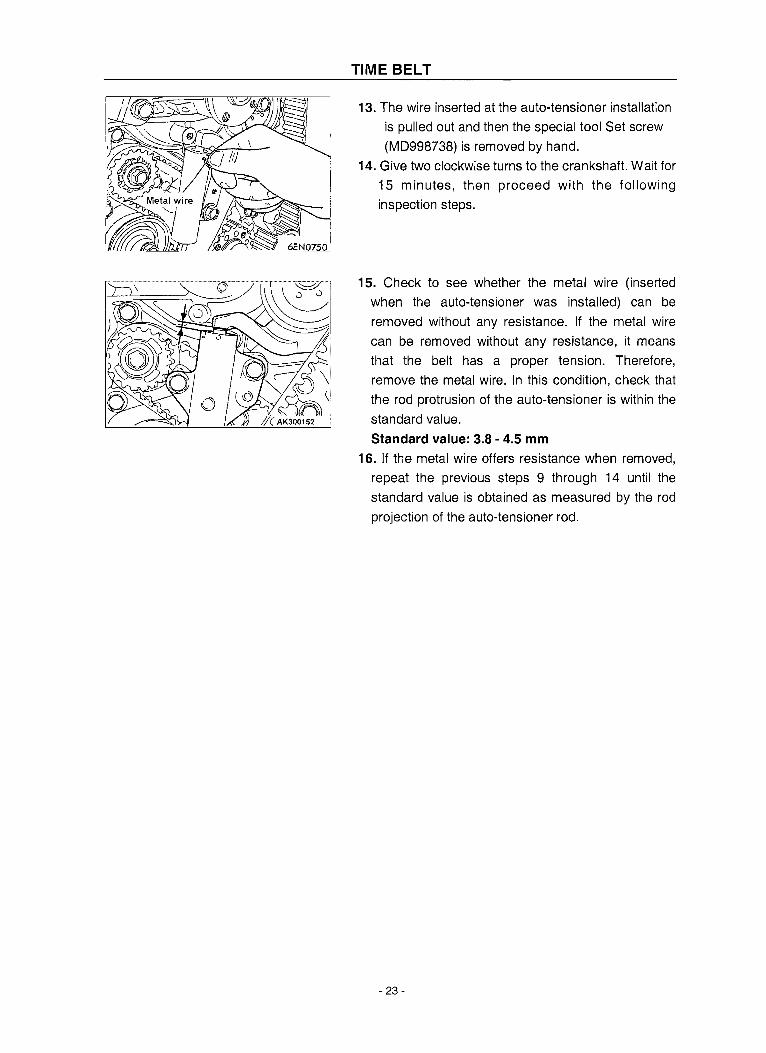
We could not possibly know of and advise the service trade of all conceivable procedures or methods by which service might be performed, or of any possible hazards and/or results of each procedure or method. Therefore, anyone who uses a procedure or method not recom-mended by the manufacturer must first satisfy himself that neither his safety, nor the product’s safety, will be endangered by the service or operating procedure selected.
All information, illustrations and specifications contained in this manual are based on the latest product information available at the time of publication. However, the manufacturer reserves the right to change, alter or otherwise improve the product at any time without prior notice. Some components or assemblies of the product described in this manual may not be considered repairable. Disassembly, repair and reassembly of such components may not be included in this manual.
The engines described herein may be used to power a wide variety of products. Service and repair instructions relating to any such products are not covered in this manual. For information pertaining to use of these engines with other products, refer to any owner’s or service manuals pertaining to said products.
This engine has been engineered for use by the manufacturer as the prime mover in a gaseous engine-driven standby generator set application. The contents of this manual have been reprinted from the original manufacturer’s service and repair manual. Due to differences in application there may be components or assemblies and procedures which do not match the information or views in this manual. Some common changes may include; intake manifold and fuel system components, ignition system compo-nents, accessory drive components, cooling fan, etc. Always consult the applicable generator parts manual for specific component parts and manufacturer part numbers which may have been substituted on the engine for this application.
SERVICE RECOMMENDATIONS .............................................................................................................................................. 2
OEM CONTENTS ............................................................................................................................................................................
2.4 Liter Gas Engine Table of Contents

2.4 Liter Gas Engine Service Recommendations
2
ENGINE OIL RECOMMENDATIONS
The unit has been filled with 5W-20 engine oil at the factory. Use a high-quality detergent oil classified “For Service SJ, SL, SH, SM, or GF-5.” Detergent oils keep the engine cleaner and reduce carbon deposits.
Crankcase Oil Capacity ......See applicable unit specification sheet
Any attempt to crank or start the engine before it has been properly serviced with the recommended oil may result in an engine failure.
NOTE:
For temperatures below 32° F, it is strongly recommended to use an appropriate Cold Weather Start Kit (consult the unit manufacturer). The recommended oil grade for temperatures below 32° F is 5W-30 synthetic oil.
COOLANT
Use a mixture of half low silicate ethylene glycol base anti-freeze and deionized or distilled water. Cooling system capacity is listed in the specifications. Use only deionized or distilled water and only low silicate anti-freeze. If desired, add a high quality rust inhibitor to the recommended coolant mixture. When adding coolant, always add the recommended 50-50 mixture.
Cooling System:Type.................................................Pressurized, Closed recovery
Coolant Capacity ................See applicable unit specification sheet.System capacity will vary depending on
type/size radiator used in the application.
Do not use any chromate base rust inhibitor with ethylene glycol base anti-freeze or chro-mium hydroxide will form (“green slime”) and cause overheating. Engines that have been operated with a chromate base rust inhibitor must be chemically cleaned before adding ethylene glycol base anti-freeze. Using any high silicate anti-freeze boost-ers or additives will also cause overheating. The manufacturer also recommends that any soluble oil inhibitor NOT be used for this equipment.
Do not remove the radiator pressure cap while the engine is hot or serious burns from boiling liquid or steam could result.
Ethylene glycol base antifreeze is poisonous. Do not use mouth to siphon coolant from the radiator, recovery bottle or any container. Wash hands thoroughly after handling. Never store used antifreeze in an open container because animals are attracted to the smell and taste of antifreeze even though it is poi-sonous to them.
2.4 Liter Gas Engine Service Recommendations
3
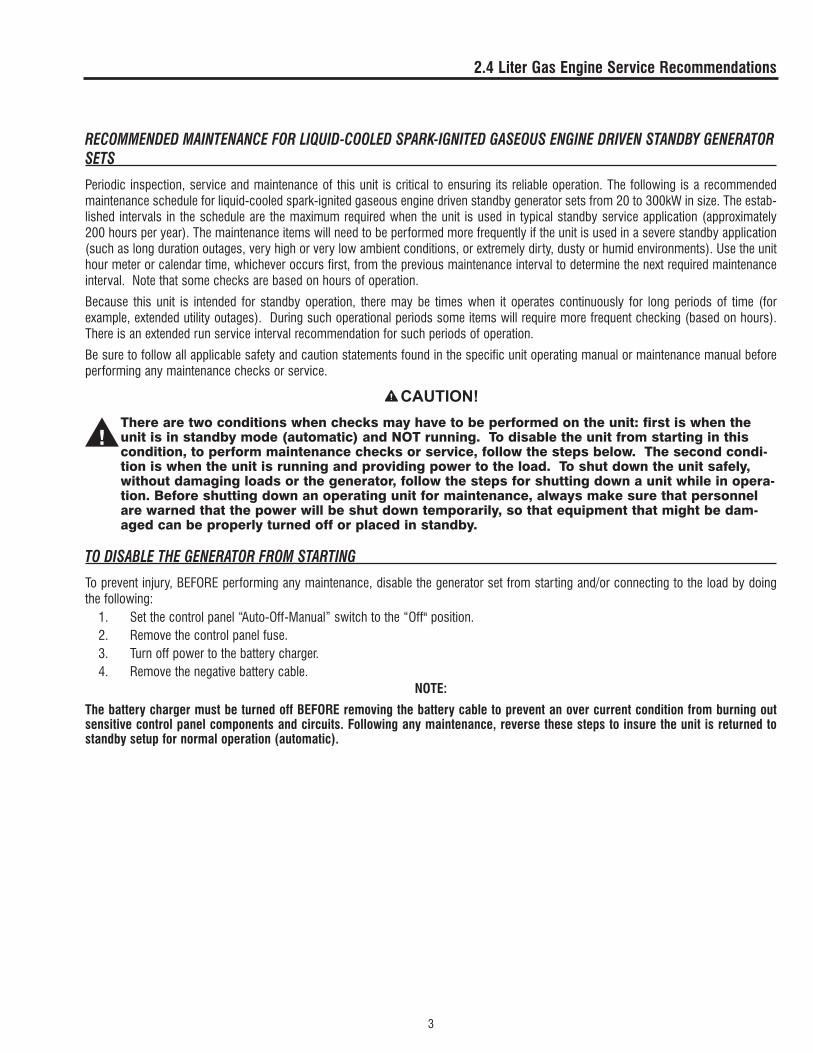
RECOMMENDED MAINTENANCE FOR LIQUID-COOLED SPARK-IGNITED GASEOUS ENGINE DRIVEN STANDBY GENERATOR SETS
Periodic inspection, service and maintenance of this unit is critical to ensuring its reliable operation. The following is a recommended maintenance schedule for liquid-cooled spark-ignited gaseous engine driven standby generator sets from 20 to 300kW in size. The estab-lished intervals in the schedule are the maximum required when the unit is used in typical standby service application (approximately 200 hours per year). The maintenance items will need to be performed more frequently if the unit is used in a severe standby application (such as long duration outages, very high or very low ambient conditions, or extremely dirty, dusty or humid environments). Use the unit hour meter or calendar time, whichever occurs first, from the previous maintenance interval to determine the next required maintenance interval. Note that some checks are based on hours of operation.
Because this unit is intended for standby operation, there may be times when it operates continuously for long periods of time (for example, extended utility outages). During such operational periods some items will require more frequent checking (based on hours). There is an extended run service interval recommendation for such periods of operation.
Be sure to follow all applicable safety and caution statements found in the specific unit operating manual or maintenance manual before performing any maintenance checks or service.
There are two conditions when checks may have to be performed on the unit: first is when the unit is in standby mode (automatic) and NOT running. To disable the unit from starting in this condition, to perform maintenance checks or service, follow the steps below. The second condi-tion is when the unit is running and providing power to the load. To shut down the unit safely, without damaging loads or the generator, follow the steps for shutting down a unit while in opera-tion. Before shutting down an operating unit for maintenance, always make sure that personnel are warned that the power will be shut down temporarily, so that equipment that might be dam-aged can be properly turned off or placed in standby.
TO DISABLE THE GENERATOR FROM STARTING
To prevent injury, BEFORE performing any maintenance, disable the generator set from starting and/or connecting to the load by doing the following:
1. Set the control panel “Auto-Off-Manual” switch to the “Off" position.2. Remove the control panel fuse.3. Turn off power to the battery charger.4. Remove the negative battery cable.
NOTE:
The battery charger must be turned off BEFORE removing the battery cable to prevent an over current condition from burning out sensitive control panel components and circuits. Following any maintenance, reverse these steps to insure the unit is returned to standby setup for normal operation (automatic).

TO SHUT DOWN AND RESTART AN OPERATING GENERATOR
If the unit is operating (for an extended run period) and required checks must be performed, do the following:1. Ensure that power to the load can be interrupted (warn any equipment users that there will be a temporary power disruption).
NOTE:
There may be other procedures required by the application/installation, before the generator can be shut down. Always check first.
2. Open the generator Main Line Circuit Breaker (MLCB).
3. Let the unit cool down (running at no-load) for approximately 5 minutes to prevent damage to critical engine components.
4. Set the control panel “Auto-Off-Manual” switch to the “Off” position. There may be safety tag-outs or lockout required at this point depending on application. Always check.
5. Perform the necessary maintenance checks or tasks (based on the hourly requirements).
6. When all checks have been completed and any discrepancies corrected, set the control panel “Auto-Off-Manual” switch to the “Auto” position.
7. When the generator is running, and all engine/generator parameters (i.e. voltage, frequency, coolant temp, oil pressure…) have been verified as correct, close the Generator Main Line Circuit Breaker (MLCB). The unit will accept and carry the load.
8. Make a last visual inspection of the generator set to make sure it is operating properly.
SERVICE MAINTENANCE INTERVAL INFORMATIONThe various service maintenance intervals are designated by interval numbers as follows:
Extended Run Time Maintenance Checks. Daily checks which must be performed when the unit is operated continuously for extended periods of time.1. A frequent, periodic inspection of the generator set to insure it is ready to operate when required and to identify any potential problem
areas. Performed monthly or following each 24 hours of operation of the unit and requires approximately .5 man-hours per unit to complete. Note: the gearbox oil (if equipped) should be checked monthly or every 100 hours of operation.
1A. A one-time post installation, initial operation, service inspection of the generator set to insure it is ready to operate, transfer to, and carry the load when required, and to identify any potential problem areas. Performed ONLY ONCE following the first three months or the first 50 hours of operation after purchase of the unit and requires approximately 2.5 man-hours per unit to com-plete.
2. An operational service inspection of the generator set to insure it is ready to operate and carry the load when required, and to identify any potential problem areas. Performed semi-annually (6 months) or following each 100 hours of operation of the unit and requires approximately 2.0 man-hours per unit to complete.
3. A mid-level service inspection of the generator set to insure it is ready to operate and carry the load when required, and to identify any potential problem areas. Performed annually or following each 200 hours of operation of the unit and requires approximately 6.0 man-hours per unit to complete.
4. A comprehensive service inspection of the generator set to insure it is properly serviced and ready to operate and carry the load when required, and to identify any potential problem areas. Performed biannually and requires approximately 8.0 man-hours per unit to complete.
MAINTENANCE SCHEDULEThe following sheets identify the maintenance tasks recommended to be accomplished for each interval. Typically maintenance level tasks are combined; for example, if the 6 month tasks are due, both the monthly and the 6 month task sheets should be completed. There are spaces for recording the date and signature of the person completing the task, as well as recording the engine hours. There is also space at the bottom of each sheet to record any fluids added or corrective action taken. All of this information, when recorded, provides a detailed maintenance history of the unit. This maintenance history may be required for warranty validation purposes, and is a good idea to maintain throughout the lifetime of the unit.
4
2.4 Liter Gas Engine Service Recommendations

Extended Run Time Maintenance Checks Maintenance Tasks Task Completed
Date/Initials1. Before shutting the unit down, perform a thorough visual inspection of the
unit for leaks, loose components or connections, excessive wear or dam-age. Any discrepancies noted should be further inspected and corrected while the unit is shut down.
Every 24 operating hours
(Requires approximately
0.5 man-hours per unit)
2. Shut the unit down per the “To Shut Down and Restart an Operating Generator” procedure.
3. Check the engine oil level. Adjust as necessary.
4. Check the engine coolant level. Adjust as necessary. Add only a 50/50 mixture of appropriate coolant.
5. Check the engine accessory drive belts and fan coupling device (if equipped) for correct tension, wear, deterioration, or damage. Correct as necessary.
6. Check all hoses and connections (coolant, block heater, oil, fuel) for tight-ness, leaks, deterioration, or damage. Correct as necessary.
7. Check the air inlets and outlets for debris or blockage. Clean as neces-sary.
8. Check the NG or LP delivery system for leaks. Tighten/repair connections as necessary.
Every 100 operating hours 9. Check the gearbox oil level (if equipped). Adjust as necessary.
Weekly when operating 10. Check the battery electrolyte level (if accessible). Adjust as necessary (add only distilled or deionized water to replenish battery cells).
11. Restart the unit per the “To Shut Down and Restart an Operating Generator” procedure. Check unit voltage and frequency. Visually inspect the unit for leaks, loose connections or components. Place the unit back in service.
Technician’s signature signify-ing inspection completed.
Date inspection completed.
Unit Hour Meter Reading at Completion of the Inspection
Record any oil or coolant added and notes about any discrepancies found and corrective action taken.
5
2.4 Liter Gas Engine Service Recommendations
6
2.4 Liter Gas Engine Service Recommendations
Maint Level
Maintenance Interval Maintenance Tasks Task Completed
Date/Initials
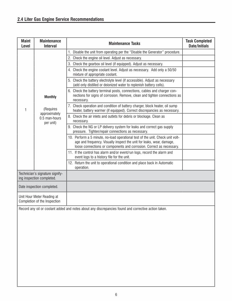
1
Monthly
(Requires approximately 0.5 man-hours
per unit)
1. Disable the unit from operating per the “Disable the Generator” procedure.
2. Check the engine oil level. Adjust as necessary.
3. Check the gearbox oil level (if equipped). Adjust as necessary.
4. Check the engine coolant level. Adjust as necessary. Add only a 50/50 mixture of appropriate coolant.
5. Check the battery electrolyte level (if accessible). Adjust as necessary (add only distilled or deionized water to replenish battery cells).
6. Check the battery terminal posts, connections, cables and charger con-nections for signs of corrosion. Remove, clean and tighten connections as necessary.
7. Check operation and condition of battery charger, block heater, oil sump heater, battery warmer (if equipped). Correct discrepancies as necessary.
8. Check the air inlets and outlets for debris or blockage. Clean as necessary.
9. Check the NG or LP delivery system for leaks and correct gas supply pressure. Tighten/repair connections as necessary.
10. Perform a 5 minute, no-load operational test of the unit. Check unit volt-age and frequency. Visually inspect the unit for leaks, wear, damage, loose connections or components and corrosion. Correct as necessary.
11. If the control has alarm and/or event/run logs, record the alarm and event logs to a history file for the unit.
12. Return the unit to operational condition and place back in Automatic operation.
Technician’s signature signify-ing inspection completed.
Date inspection completed.
Unit Hour Meter Reading at Completion of the Inspection
Record any oil or coolant added and notes about any discrepancies found and corrective action taken.

7
2.4 Liter Gas Engine Service Recommendations
Maint Level
Maintenance Interval Maintenance Tasks Task Completed
Date/Initials
1A
At first 3 months of operation or after the first 50 hours of operation only.
Do these tasks in addition to the
regularly scheduled monthly mainte-
nance tasks.
(Requiresapproximately 2.5 man-hours
per unit)
1. Disable the unit from operating per the “Disable the Generator” procedure. In addition to the Monthly scheduled maintenance tasks, perform the fol-lowing:
2. Change the engine oil.
3. Change the engine oil filter(s).
4. Check engine valve clearance (valve lash) as specified in the engine service manual. NOTE: this is not required for engines with hydraulic lifters.
5. Check the engine accessory drive belts and fan coupling device (if equipped) for correct tension, wear, deterioration, or damage. Correct as necessary.
6. Check all hoses and connections (coolant, block heater, oil, fuel) for tight-ness, leaks, deterioration, or damage. Correct as necessary.
7. Check wiring connections (at MLCB, customer connections and control panel) for loose connections, corrosion or damage. Correct as neces-sary.
8. Return the unit to operational condition and test. Place the unit in auto-matic and open the service disconnect to force the unit to start and trans-fer to the load. Exercise the unit against the load for 15 minutes, visually inspecting for leaks, loose connections or components, and any abnormal operating conditions. Record the unit voltage and frequency while run-ning. Restore utility power and monitor transfer to utility, cool-down and shutdown. Correct any discrepancies.
9. If the control has alarm and/or event/run logs, record the alarm and event logs to a history file for the unit.
10. Return the unit to operational condition.
Technician’s signature signify-ing inspection completed.
Date inspection completed.
Unit Hour Meter Reading at Completion of the Inspection
Record any oil or coolant added and notes about any discrepancies found and corrective action taken.

8
2.4 Liter Gas Engine Service Recommendations
Maint Level
Maintenance Interval Maintenance Tasks Task Completed
Date/Initials
2
Every 6 months
Do these tasks in addition to
the regularlyscheduled monthly maintenance tasks.
(Requiresapproximately 2.0 man-hours
per unit)
1. Disable the unit from operating per the “Disable the Generator” procedure. In addition to the Monthly scheduled maintenance tasks, perform the following:
2. Check the engine accessory drive belts and fan coupling device (if equipped) for correct tension, wear, deterioration, or damage. Correct as necessary.
3. Check all hoses and connections (coolant, block heater, oil, fuel) for tightness, leaks, deterioration, or damage. Correct as necessary.
4. Load test the battery or test electrolyte levels (specific gravity) with a hydrometer. Correct condition or replace battery as needed.
5. Return the unit to operational condition and test. Place the unit in auto-matic and open the service disconnect to force the unit to start and trans-fer to the load. Exercise the unit against the load for at least 30 minutes, and visually inspect for leaks, loose connections or components, and any abnormal operating conditions. Restore utility power and monitor transfer to utility, cool-down and shutdown. Correct any discrepancies.
6. If the control has alarm and/or event/run logs, record the alarm and event logs to a history file for the unit.
7. Return the unit to operational condition and place back in Automatic operation.
Technician’s signature signify-ing inspection completed.
Date inspection completed.
Unit Hour Meter Reading at Completion of the Inspection
Record any oil or coolant added and notes about any discrepancies found and corrective action taken.
9
2.4 Liter Gas Engine Service Recommendations
Maint Level
Maintenance Interval Maintenance Tasks Task Completed
Date/Initials
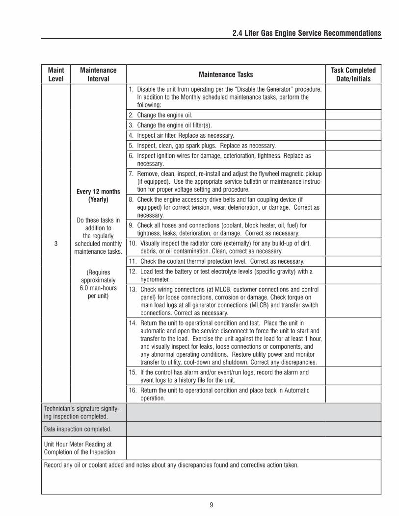
3
Every 12 months(Yearly)
Do these tasks in addition to
the regularlyscheduled monthly maintenance tasks.
(Requiresapproximately 6.0 man-hours
per unit)
1. Disable the unit from operating per the “Disable the Generator” procedure. In addition to the Monthly scheduled maintenance tasks, perform the following:
2. Change the engine oil.
3. Change the engine oil filter(s).
4. Inspect air filter. Replace as necessary.
5. Inspect, clean, gap spark plugs. Replace as necessary.
6. Inspect ignition wires for damage, deterioration, tightness. Replace as necessary.
7. Remove, clean, inspect, re-install and adjust the flywheel magnetic pickup (if equipped). Use the appropriate service bulletin or maintenance instruc-tion for proper voltage setting and procedure.
8. Check the engine accessory drive belts and fan coupling device (if equipped) for correct tension, wear, deterioration, or damage. Correct as necessary.
9. Check all hoses and connections (coolant, block heater, oil, fuel) for tightness, leaks, deterioration, or damage. Correct as necessary.
10. Visually inspect the radiator core (externally) for any build-up of dirt, debris, or oil contamination. Clean, correct as necessary.
11. Check the coolant thermal protection level. Correct as necessary.
12. Load test the battery or test electrolyte levels (specific gravity) with a hydrometer.
13. Check wiring connections (at MLCB, customer connections and control panel) for loose connections, corrosion or damage. Check torque on main load lugs at all generator connections (MLCB) and transfer switch connections. Correct as necessary.
14. Return the unit to operational condition and test. Place the unit in automatic and open the service disconnect to force the unit to start and transfer to the load. Exercise the unit against the load for at least 1 hour, and visually inspect for leaks, loose connections or components, and any abnormal operating conditions. Restore utility power and monitor transfer to utility, cool-down and shutdown. Correct any discrepancies.
15. If the control has alarm and/or event/run logs, record the alarm and event logs to a history file for the unit.
16. Return the unit to operational condition and place back in Automatic operation.
Technician’s signature signify-ing inspection completed.
Date inspection completed.
Unit Hour Meter Reading at Completion of the Inspection
Record any oil or coolant added and notes about any discrepancies found and corrective action taken.

10
2.4 Liter Gas Engine Service Recommendations
Maint Level
Maintenance Interval Maintenance Tasks Task Completed
Date/Initials
4
Every 24 months(Bi-Annually)
Do these tasks in addition to
the regularlyscheduled Monthly
and Yearlymaintenance
tasks.
(Requiresapproximately 8.0 man-hours
per unit)
1. Disable the unit from operating per the “Disable the Generator” procedure. In addition to the Monthly and Yearly scheduled maintenance tasks, per-form the following:
2. Change the gearbox oil (if equipped) (or at 600 hours).
3. Replace the engine air filter.
4. Replace the engine spark plugs; gap per the engine specifications.
5. Replace the engine accessory drive belts. Inspect the belt tensioner (if equipped) and replace if necessary.
6. Drain and flush the cooling system. Refill with fresh coolant of appropriate type (50/50 mixture).
7. Replace all coolant hoses, including the hoses to/from the block heater and/or vaporizer (if equipped).
8. Replace all flexible fuel hoses.
9. Return the unit to operational condition and test. Place the unit in auto-matic and open the service disconnect to force the unit to start and transfer to the load. Use a load bank and bring the unit to full rated load (100%kW, at rated kVA) if possible. Exercise the unit against the load for at least 2 hours, and visually inspect for leaks, loose connections or com-ponents, and any abnormal operating conditions. Remove the load bank load, restore utility power and monitor transfer to utility, cool-down and shutdown. Correct any discrepancies.
10. If the control has alarm and/or event/run logs, record the alarm and event logs to a history file for the unit.
11. Return the unit to operational condition and place back in Automatic operation.
Technician’s signature signify-ing inspection completed.
Date inspection completed.
Unit Hour Meter Reading at Completion of the Inspection
Record any oil or coolant added and notes about any discrepancies found and corrective action taken.


SPECIFICATIONS
TORQUE SPECIFICATIONS
Item Specification (ft-lbs)
Ignition system
Ignition coil 7.2
Crankshaft pulley bolts 18
Spark plugs 18
Water pump pulley bolts 6.5
Exhaust manifold
Water pump bolts 10
Thermostat housing bolts 17.5
Timing belt
Auto-tensioner bolts 17.5
Camshaft sprocket bolt 65
Counterbalance shaft sprocket bolt 33
Crankshaft bolt 87
Engine support bracket bolt 35
Idler pulley bolt 26
Oil pump sprocket nut 40
Tensioner "B" bolt 14
Tensioner arm bolt 16
Tensioner pulley bolt 35
Timing belt cover bolts (bolt, washer assembly) 8
Timing belt cover bolts (flange bolt and nut) 8
Inlet manifold and water pump
Engine hanger bolt 14
Pressure switch 7.2
Water temp gauge 21.5
Water outlet fitting bolts 14.5
Rocker arms and camshaft
Rocker arms and rocker arm shaft bolts 23
Rocker cover bolts 3
Thrust screw 14
SPECIFICATIONS
Item Specification (ft-lbs)
Cylinder head and valves
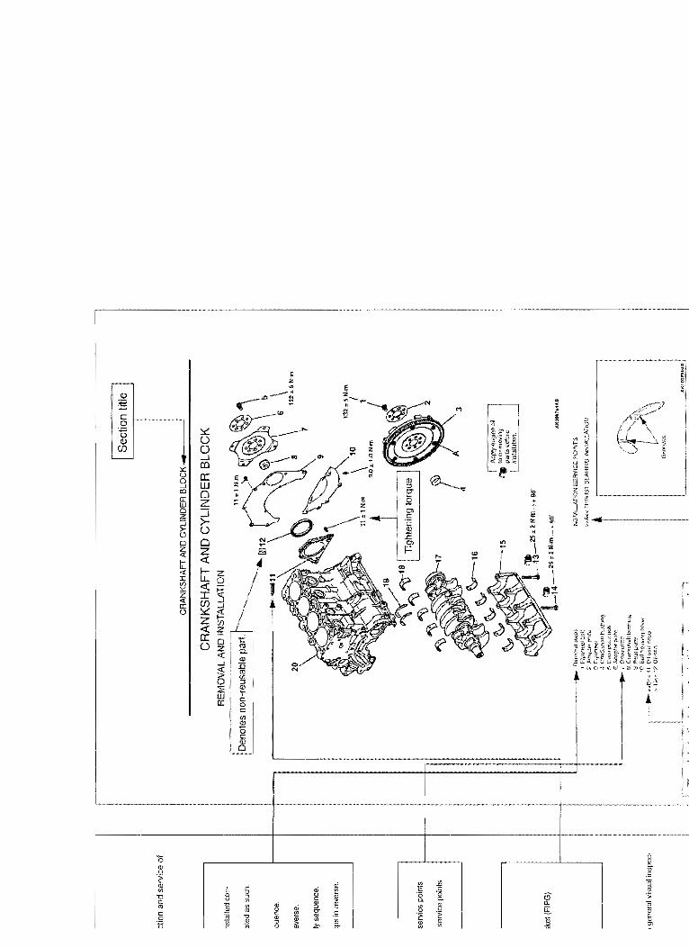
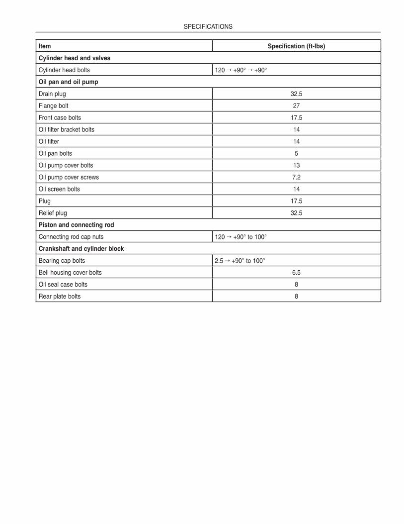
Cylinder head bolts 120 → +90° → +90°
Oil pan and oil pump
Drain plug 32.5
Flange bolt 27
Front case bolts 17.5
Oil filter bracket bolts 14
Oil filter 14
Oil pan bolts 5
Oil pump cover bolts 13
Oil pump cover screws 7.2
Oil screen bolts 14
Plug 17.5
Relief plug 32.5
Piston and connecting rod
Connecting rod cap nuts 120 → +90° to 100°
Crankshaft and cylinder block
Bearing cap bolts 2.5 → +90° to 100°
Bell housing cover bolts 6.5
Oil seal case bolts 8
Rear plate bolts 8


Notes

Notes

Part No. 0G2832 Revision C (04/19/12) Printed in U.S.A.
Related Documents