Analysentechnik Installation and Operation Instructions Original instructions Peristaltic pumps CPsingle X1, CPdouble X1 BE450026 09/2018 Bühler Technologies GmbH, Harkortstr. 29, D-40880 Ratingen Tel. +49 (0) 21 02 / 49 89-0, Fax: +49 (0) 21 02 / 49 89-20 E-Mail: [email protected] Internet: www.buehler-technologies.com

Welcome message from author
This document is posted to help you gain knowledge. Please leave a comment to let me know what you think about it! Share it to your friends and learn new things together.
Transcript
Analysentechnik
Installation and Operation Instructions
Original instructions
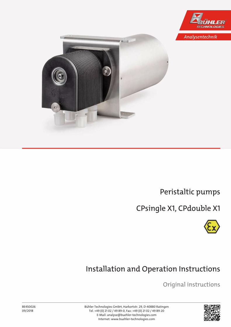
Peristaltic pumps
CPsingle X1, CPdouble X1
BE450026
09/2018
Bühler Technologies GmbH, Harkortstr. 29, D-40880 Ratingen
Tel. +49 (0) 21 02 / 49 89-0, Fax: +49 (0) 21 02 / 49 89-20
E-Mail: [email protected]
Internet: www.buehler-technologies.com
Bühler Technologies GmbH, Harkortstr. 29, D-40880 Ratingen
Tel. +49 (0) 21 02 / 49 89-0, Fax: +49 (0) 21 02 / 49 89-20
Internet: www.buehler-technologies.com
E-Mail: [email protected]
Read this instruction carefully prior to installation and/or use. Pay at-
tention particularly to all advises and safety instructions to prevent in-
juries. Bühler Technologies can not be held responsible for misusing
the product or unreliable function due to unauthorised modifications.
All rights reserved. Bühler Technologies GmbH 2018
Document information
Document No..........................................................BE450026
Version.........................................................................09/2018
CPsingle X1, CPdouble X1
Contents1 Introduction..................................................................................................................................................................................................................... 2
1.1 Intended use ......................................................................................................................................................................................................... 2
1.2 Scope of delivery .................................................................................................................................................................................................. 2
1.3 Type plate .............................................................................................................................................................................................................. 2
1.4 Peristaltic pump ordering information........................................................................................................................................................ 2
2 Safety instructions......................................................................................................................................................................................................... 3
2.1 Important advice ................................................................................................................................................................................................. 3
2.2 General hazard warnings ................................................................................................................................................................................. 4
3 Transport and storage .................................................................................................................................................................................................. 5
4 Installation and connection ........................................................................................................................................................................................ 6
4.1 Installation site requirements......................................................................................................................................................................... 6
4.2 Mounting............................................................................................................................................................................................................... 6
4.3 Electrical connections ........................................................................................................................................................................................ 6
5 Operation and control .................................................................................................................................................................................................. 8
6 Maintenance.................................................................................................................................................................................................................... 9
6.1 Maintenance Schedule ...................................................................................................................................................................................... 9
6.2 Replacing the hose ............................................................................................................................................................................................ 10
6.3 Changing the pump head/rotor .................................................................................................................................................................... 11
7 Service and repair.......................................................................................................................................................................................................... 12
7.1 Safety instructions ............................................................................................................................................................................................ 12
7.2 Spare parts and accessories ............................................................................................................................................................................ 13
7.2.1 Ordering information replacement hoses for 0.3 l/h pumps ............................................................................................... 13
8 Disposal ........................................................................................................................................................................................................................... 14
9 Appendices...................................................................................................................................................................................................................... 15
9.1 Technical data ..................................................................................................................................................................................................... 15
9.2 Dimensions of peristaltic pumps 115 / 230 V.............................................................................................................................................. 15
9.2.1 Version with 1 gas path..................................................................................................................................................................... 15
9.2.2 Version with 2 gas paths .................................................................................................................................................................. 16
10 Attached documents .................................................................................................................................................................................................... 17
iBühler Technologies GmbHBE450026 ◦ 09/2018
CPsingle X1, CPdouble X1
1 Introduction
1.1 Intended useThis unit is intended to discharge condensate from cooled process fluids. The temperature of these mediums is approx. 5 °C.
These operating instructions apply to pressurised encapsulation with surface-cooled electric motors for low voltage, degree of
protection IP40, IP54, IP64, IP65 EN 60034-5:2001+A1:2007.
The motor is ignition protection type Ex db, designed for Zone 1 (ATEX and IECEx).
The competent supervisory authority or the operator is responsible for determining the degree of explosion hazard of an operat-
ing site.
The electric motor may only be used for continuous duty, not for frequent starting without significant start-up warming.
The pump may be used in explosive areas Zone 1 and 2. Explosion group IIB, temperature class T4.
1.2 Scope of delivery– 1 x Peristaltic pump
– Product Documentation
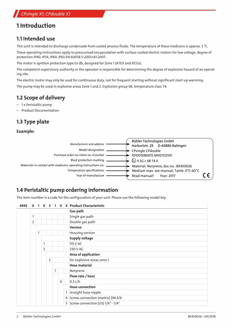
1.3 Type plate
Example:
CPsingle CPdouble
101001080015 44921123101
Manufacturer and address
Model designation
Purchase order no.+Item no.+Counter
Blast protection marking
Materials in contact with mediums, operating instructions no.
Temperature specifications
Year of manufacture
II 2G c IIB T4 X
Material: Norprene, doc.no.: BX450026
Medium max: see manual; Tamb: 0°C-60°C
Read manual! Year: 2017
Bühler Technologies GmbH
Harkortstr. 29 D-40880 Ratingen
1.4 Peristaltic pump ordering informationThe item number is a code for the configuration of your unit. Please use the following model key:
4492 X 1 X 3 1 0 X Product Characteristic
Gas path
1 Single gas path
2 Double gas path
Version
1 Housing version
Supply voltage
1 115 V AC
3 230 V AC
Area of application
3 for explosive areas zone 1
Hose material
1 Norprene
Flow rate / hour
0 0.3 L/h
Hose connection
1 straight hose nipple
4 Screw connection (metric) DN 4/6
5 Screw connection (US) 1/6" - 1/4"
2 Bühler Technologies GmbH BE450026 ◦ 09/2018
CPsingle X1, CPdouble X1
2 Safety instructions
2.1 Important adviceThis unit may only be used if:
– The product is being used under the conditions described in the operating- and system instructions, used according to the
nameplate and for applications for which it is intended. Any unauthorized modifications of the device will void the warranty
provided by Bühler Technologies GmbH,
– The specifications and markings in the type plate are observed,
– The limits in the data sheet and the instructions must be observed,
– Monitoring equipment / protection devices must be connected correctly,
– Service and repair work not described in these instructions is performed by Bühler Technologies GmbH,
– Using genuine replacement parts.
Regulation IEC/EN 60079-14 must be observed when erecting electrical systems in explosive areas.
Additional national regulations pertaining to initial operation, operation, maintenance, repairs, and disposal must be observed.
These operating instructions are a part of the equipment. The manufacturer reserves the right to change performance-, specific-
ation- or technical data without prior notice. Please keep these instructions for future reference.
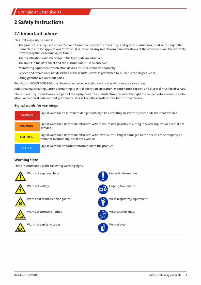
Signal words for warnings
DANGERSignal word for an imminent danger with high risk, resulting in severe injuries or death if not avoided.
WARNINGSignal word for a hazardous situation with medium risk, possibly resulting in severe injuries or death if not
avoided.
CAUTIONSignal word for a hazardous situation with low risk, resulting in damaged to the device or the property or
minor or medium injuries if not avoided.
NOTICESignal word for important information to the product.
Warning signs
These instructions use the following warning signs:
Warns of a general hazard General information
Warns of voltage Unplug from mains
Warns not to inhale toxic gasses Wear respiratory equipment
Warns of corrosive liquids Wear a safety mask
Warns of explosive areas Wear gloves
3Bühler Technologies GmbHBE450026 ◦ 09/2018
CPsingle X1, CPdouble X1
2.2 General hazard warningsThe equipment must be installed by a professional familiar with the safety requirements and risks.
Be sure to observe the safety regulations and generally applicable rules of technology relevant for the installation site. Prevent
malfunctions and avoid personal injuries and property damage.
The operator of the system must ensure:
– Safety notices and operating instructions are available and observed,
– The respective national accident prevention regulations are observed,
– The permissible data and operational conditions are maintained,
– Safety guards are used and mandatory maintenance is performed,
– Legal regulations are observed during disposal.
Maintenance, Repair
Please note during maintenance and repairs:
– Repairs to the unit must be performed by Bühler authorised personnel.
– Only perform conversion-, maintenance or installation work described in these operating and installation instructions.
– Always use genuine spare parts.
Always observe the applicable safety and operating regulations in the respective country of use when performing any type of
maintenance.
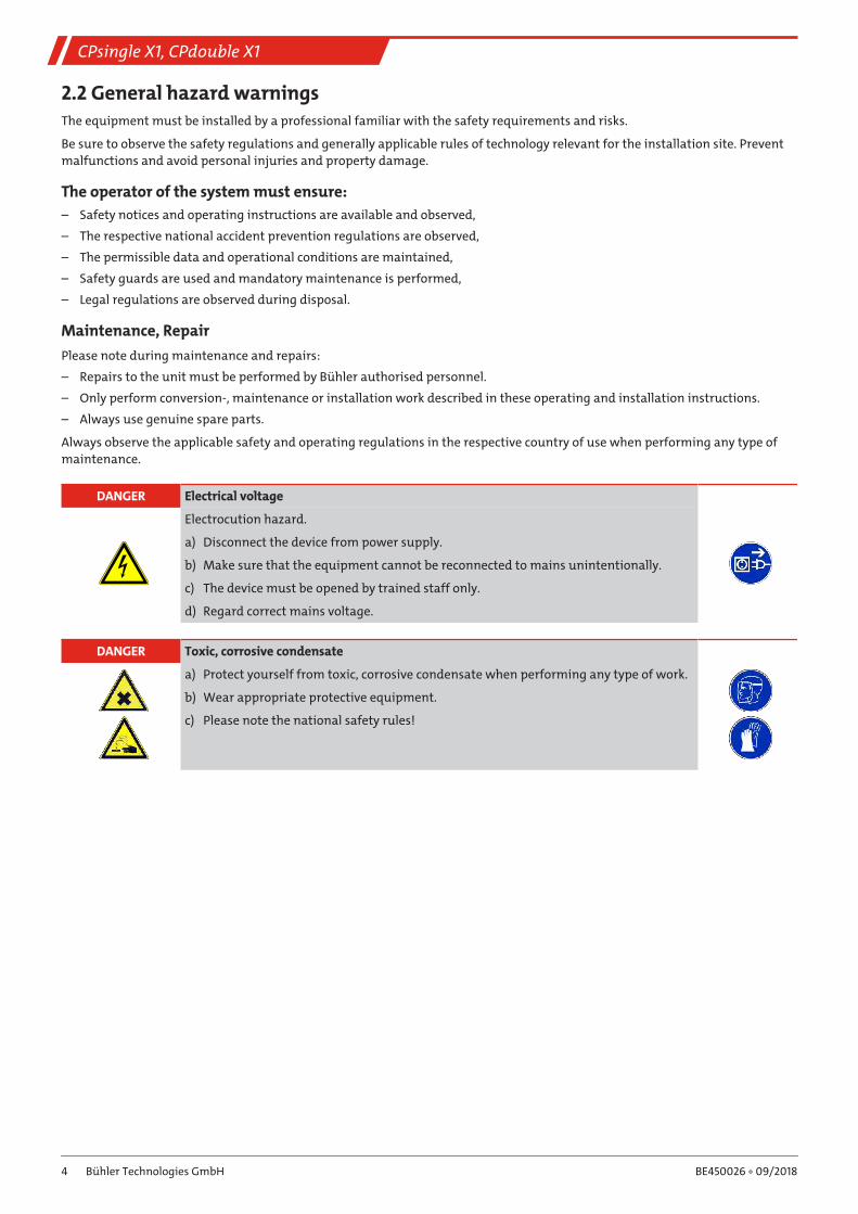
DANGER Electrical voltage
Electrocution hazard.
a) Disconnect the device from power supply.
b) Make sure that the equipment cannot be reconnected to mains unintentionally.
c) The device must be opened by trained staff only.
d) Regard correct mains voltage.
DANGER Toxic, corrosive condensate
a) Protect yourself from toxic, corrosive condensate when performing any type of work.
b) Wear appropriate protective equipment.
c) Please note the national safety rules!
4 Bühler Technologies GmbH BE450026 ◦ 09/2018
CPsingle X1, CPdouble X1
3 Transport and storageThe products should be transported only in its original packaging or a suitable replacement.
When not in use, protect the equipment against moisture and heat. Keep it in a covered, dry and dust-free room.
5Bühler Technologies GmbHBE450026 ◦ 09/2018
CPsingle X1, CPdouble X1
4 Installation and connection
4.1 Installation site requirementsBe sure to maintain the approved ambient temperature. Please also note the technical data of the add-on gas cooler.
When mounting to a subframe, it screws directly onto the cooler housing frame.
The unit is intended for use in enclosed areas. Adequate protection from the weather must be provided when used outdoors.
The pressurised encapsulation must be protected from sunlight to prevent prohibited heating.
The ambient temperature is 0 °C to +60 °C.
The minimum bend radius of the connecting cable is 55 mm.
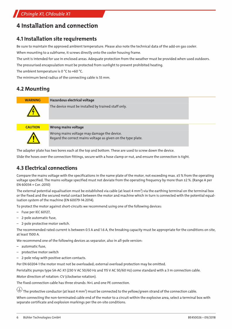
4.2 Mounting
WARNING Hazardous electrical voltage
The device must be installed by trained staff only.
CAUTION Wrong mains voltage
Wrong mains voltage may damage the device.
Regard the correct mains voltage as given on the type plate.
The adapter plate has two bores each at the top and bottom. These are used to screw down the device.
Slide the hoses over the connection fittings, secure with a hose clamp or nut, and ensure the connection is tight.
4.3 Electrical connectionsCompare the mains voltage with the specifications in the name plate of the motor, not exceeding max. ±5 % from the operating
voltage specified. The mains voltage specified must not deviate from the operating frequency by more than ±2 %. (Range A per
EN 60034 + Cor.:2010)
The external potential equalisation must be established via cable (at least 4 mm2) via the earthing terminal on the terminal box
or the fixed and the secured metal contact between the motor and machine which in turn is connected with the potential equal-
isation system of the machine (EN 60079-14:2014).
To protect the motor against short-circuits we recommend using one of the following devices:
– Fuse per IEC 60127,
– 2-pole automatic fuse,
– 2-pole protective motor switch.
The recommended rated current is between 0.5 A and 1.6 A, the breaking capacity must be appropriate for the conditions on site,
at least 1500 A.
We recommend one of the following devices as separator, also in all-pole version:
– automatic fuse,
– protective motor switch
– 2-pole relay with positive-action contacts.
Per EN 60204-1 the motor must not be overloaded; external overload protection may be omitted.
Peristaltic pumps type SA-AC-X1 (230 V AC 50/60 Hz and 115 V AC 50/60 Hz) come standard with a 3 m connection cable.
Motor direction of rotation: CV (clockwise rotation).
The fixed connection cable has three strands: N+L and one PE connection.
The protective conductor (at least 4 mm2) must be connected to the yellow/green strand of the connection cable.
When connecting the non-terminated cable end of the motor to a circuit within the explosive area, select a terminal box with
separate certificate and explosion markings per the on-site conditions.
6 Bühler Technologies GmbH BE450026 ◦ 09/2018
CPsingle X1, CPdouble X1
Be sure to observe any varying information in the rating plate. The conditions at the site must correspond with all rating plate
information.
Protective measures against prohibited heating
Unless otherwise certified, the electric motor may only be used for continuous operation, not frequent restarting without signi-
ficant start-up warming.
7Bühler Technologies GmbHBE450026 ◦ 09/2018
CPsingle X1, CPdouble X1
5 Operation and control
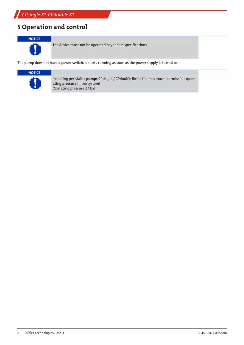
NOTICE
The device must not be operated beyond its specifications.
The pump does not have a power switch. It starts running as soon as the power supply is turned on.
NOTICE
Installing peristaltic pumps CPsingle / CPdouble limits the maximum permissible oper-
ating pressure in the system!
Operating pressure ≤ 1 bar
8 Bühler Technologies GmbH BE450026 ◦ 09/2018
CPsingle X1, CPdouble X1
6 MaintenanceDuring maintenance, remember:
– The equipment must be maintained by a professional familiar with the safety requirements and risks.
– Only perform maintenance work described in these operating and installation instructions.
– When performing maintenance of any type, observe the respective safety and operation regulations.
DANGER Electrical voltage
Electrocution hazard.
a) Disconnect the device from power supply.
b) Make sure that the equipment cannot be reconnected to mains unintentionally.
c) The device must be opened by trained staff only.
d) Regard correct mains voltage.
DANGER Toxic, corrosive condensate
Protect yourself from toxic, corrosive condensate when performing any type of work.
Wear appropriate protective equipment.
Cleaning the pump head
Dust and output from the pump hose contaminate the pump head. Regular visual inspection and, if necessary, cleaning in-
crease the pump life. The individual parts can be wiped clean dry. Never use solvents, as these are harmful to plastic. The pump
head can also be blown out with oil-free compressed air.
The motor is maintenance-free.
The hose inside the pumps is a wear item and must regularly be checked for leaks.
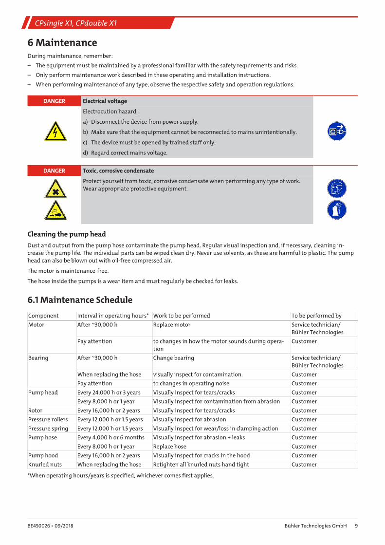
6.1 Maintenance Schedule
Component Interval in operating hours* Work to be performed To be performed by
Motor After ~30,000 h Replace motor Service technician/
Bühler Technologies
Pay attention to changes in how the motor sounds during opera-
tion
Customer
Bearing After ~30,000 h Change bearing Service technician/
Bühler Technologies
When replacing the hose visually inspect for contamination. Customer
Pay attention to changes in operating noise Customer
Pump head Every 24,000 h or 3 years Visually inspect for tears/cracks Customer
Every 8,000 h or 1 year Visually inspect for contamination from abrasion Customer
Rotor Every 16,000 h or 2 years Visually inspect for tears/cracks Customer
Pressure rollers Every 12,000 h or 1.5 years Visually inspect for abrasion Customer
Pressure spring Every 12,000 h or 1.5 years Visually inspect for wear/loss in clamping action Customer
Pump hose Every 4,000 h or 6 months Visually inspect for abrasion + leaks Customer
Every 8,000 h or 1 year Replace hose Customer
Pump hood Every 16,000 h or 2 years Visually inspect for cracks in the hood Customer
Knurled nuts When replacing the hose Retighten all knurled nuts hand tight Customer
*When operating hours/years is specified, whichever comes first applies.
9Bühler Technologies GmbHBE450026 ◦ 09/2018
CPsingle X1, CPdouble X1
6.2 Replacing the hose– Close gas supply.
– Switch off device and disconnect all plugs (e.g. connector plug alarm output, supply input, etc.).
– Disconnect supply and discharge tube on peristaltic pump (observe safety notes!).
– Loosen but do not remove centre knurled nut on the hammer-head screw. Flip down screw.
– Pull cover up and off.
– Unplug external connections and remove hose.
– Replace hose (Bühler spare part) and install peristaltic pump in reverse order.
– Restore the power and gas supply.
NOTICE Never grease the pump hose!
Check all parts for contamination prior to assembly and clean as necessary.
10 Bühler Technologies GmbH BE450026 ◦ 09/2018
CPsingle X1, CPdouble X1
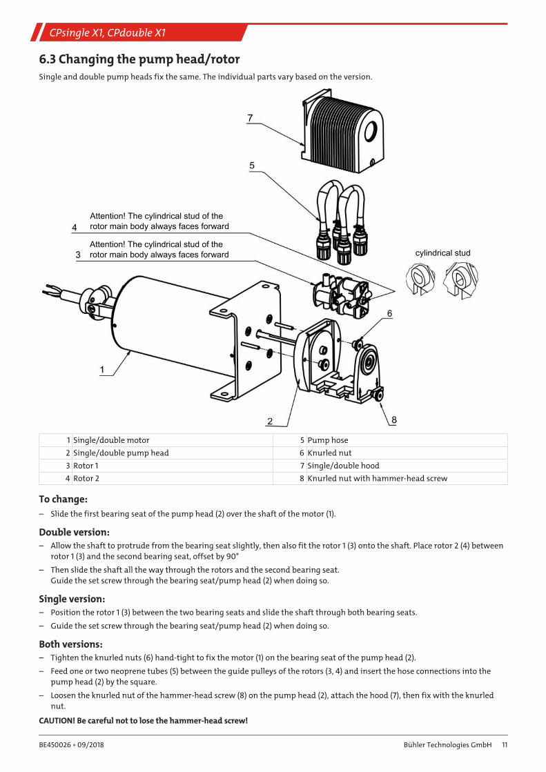
6.3 Changing the pump head/rotorSingle and double pump heads fix the same. The individual parts vary based on the version.
Attention! The cylindrical stud of the rotor main body always faces forward
Attention! The cylindrical stud of the rotor main body always faces forward cylindrical stud
1 Single/double motor 5 Pump hose
2 Single/double pump head 6 Knurled nut
3 Rotor 1 7 Single/double hood
4 Rotor 2 8 Knurled nut with hammer-head screw
To change:
– Slide the first bearing seat of the pump head (2) over the shaft of the motor (1).
Double version:– Allow the shaft to protrude from the bearing seat slightly, then also fit the rotor 1 (3) onto the shaft. Place rotor 2 (4) between
rotor 1 (3) and the second bearing seat, offset by 90°
– Then slide the shaft all the way through the rotors and the second bearing seat.
Guide the set screw through the bearing seat/pump head (2) when doing so.
Single version:– Position the rotor 1 (3) between the two bearing seats and slide the shaft through both bearing seats.
– Guide the set screw through the bearing seat/pump head (2) when doing so.
Both versions:– Tighten the knurled nuts (6) hand-tight to fix the motor (1) on the bearing seat of the pump head (2).
– Feed one or two neoprene tubes (5) between the guide pulleys of the rotors (3, 4) and insert the hose connections into the
pump head (2) by the square.
– Loosen the knurled nut of the hammer-head screw (8) on the pump head (2), attach the hood (7), then fix with the knurled
nut.
CAUTION! Be careful not to lose the hammer-head screw!
11Bühler Technologies GmbHBE450026 ◦ 09/2018
CPsingle X1, CPdouble X1
7 Service and repairThis chapter contains information on troubleshooting and correction should an error occur during operation.
Repairs to the unit must be performed by Bühler authorised personnel.
Please contact our Service Department with any questions:
Tel.: +49-(0)2102-498955 or your agent
If the equipment is not functioning properly after correcting any malfunctions and switching on the power, it must be inspected
by the manufacturer. Please send the equipment inside suitable packaging to:
Bühler Technologies GmbH
- Reparatur/Service -
Harkortstraße 29
40880 Ratingen
Germany
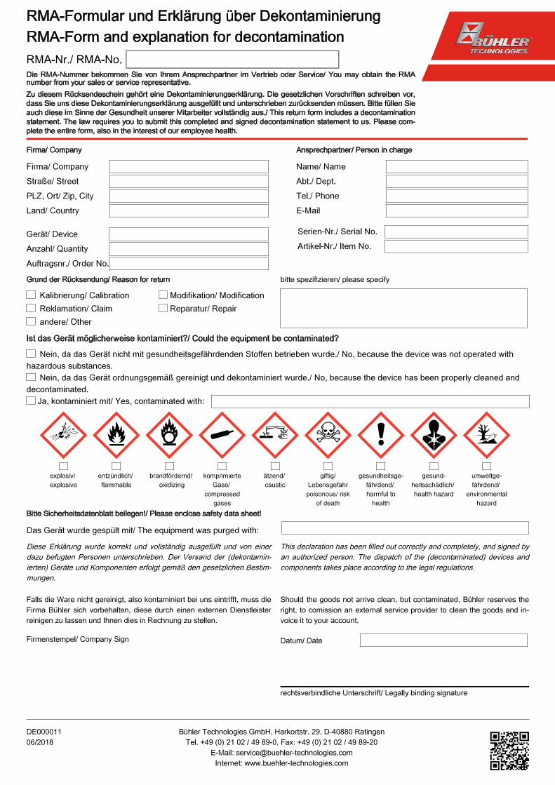
Please also attach the completed and signed RMA decontamination statement to the packaging. We will otherwise be unable to
process your repair order.
You will find the form in the appendix of these instructions, or simply request it by e-mail:
7.1 Safety instructions– The device must be operated within its specifications.
– All repairs must be carried out by Bühler authorised personnel only.
– Only perform modifications, servicing or mounting described in this manual.
– Only use original spare parts.
DANGER Electrical voltage
Electrocution hazard.
a) Disconnect the device from power supply.
b) Make sure that the equipment cannot be reconnected to mains unintentionally.
c) The device must be opened by trained staff only.
d) Regard correct mains voltage.
DANGER Toxic, corrosive condensate
Protect yourself from toxic, corrosive condensate when performing any type of work.
Wear appropriate protective equipment.
12 Bühler Technologies GmbH BE450026 ◦ 09/2018
CPsingle X1, CPdouble X1
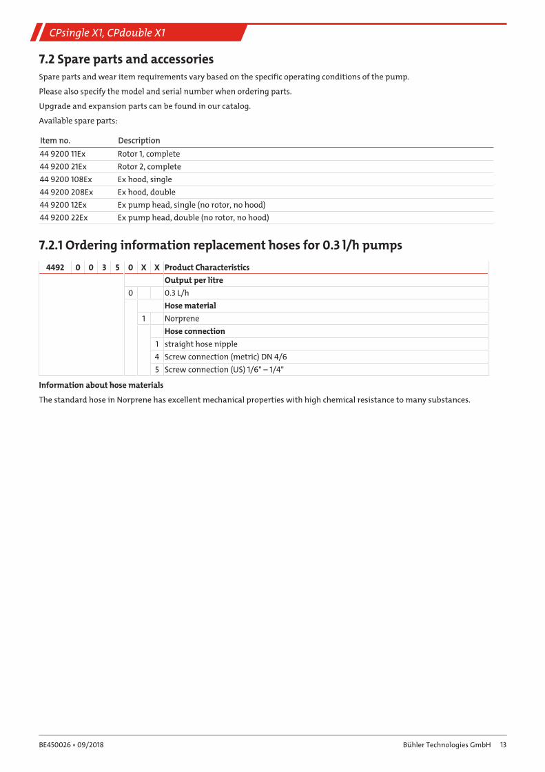
7.2 Spare parts and accessoriesSpare parts and wear item requirements vary based on the specific operating conditions of the pump.
Please also specify the model and serial number when ordering parts.
Upgrade and expansion parts can be found in our catalog.
Available spare parts:
Item no. Description
44 9200 11Ex Rotor 1, complete
44 9200 21Ex Rotor 2, complete
44 9200 108Ex Ex hood, single
44 9200 208Ex Ex hood, double
44 9200 12Ex Ex pump head, single (no rotor, no hood)
44 9200 22Ex Ex pump head, double (no rotor, no hood)
7.2.1 Ordering information replacement hoses for 0.3 l/h pumps
4492 0 0 3 5 0 X X Product Characteristics
Output per litre
0 0.3 L/h
Hose material
1 Norprene
Hose connection
1 straight hose nipple
4 Screw connection (metric) DN 4/6
5 Screw connection (US) 1/6" – 1/4"
Information about hose materials
The standard hose in Norprene has excellent mechanical properties with high chemical resistance to many substances.
13Bühler Technologies GmbHBE450026 ◦ 09/2018
CPsingle X1, CPdouble X1
8 DisposalDispose of parts so as not to endanger the health or environment.
Do not dispose of the electric motor and the pressurised encapsulation as unsorted municipal waste. If necessary, return directly
to the manufacturer.
Follow the laws in the country of use for disposing of electronic components and devices during disposal.
14 Bühler Technologies GmbH BE450026 ◦ 09/2018
CPsingle X1, CPdouble X1
9 Appendices
9.1 Technical data
Technical Data CPsingle/CPdouble Peristaltic Pumps
Nominal voltage / power input:
at Tamb = 20 °C and under load
230 V 50/60 Hz, 0.026 A (50/60 Hz)
115 V 50/60 Hz, 0.052 A (50/60 Hz)
±5 % voltage, ±2 % frequency
Flow rate: 0.3 L/h (50 Hz)/0.36 L/h (60 Hz) with standard hose
Inlet vacuum: max. 0.8 bar
Inlet pressure: max. 1 bar
Output pressure: 1 bar
Degree of protection: IP 40
Ambient temperature: 0…60 °C
Cord length: 3 m
Materials
Hose:
Connections:
Norprene (standard)
PVDF
Motor markings: ATEX: II 2G Ex db IIB T4 Gb
IECEx: Ex db IIB T4 Gb
Pump marking: II 2G c IIB T4 X
The motor may be operated without protective circuit and depending on the housing length is designed for maximum heating
in the event of a fault.
The expected life of the motor is over 30,000 operating hours.
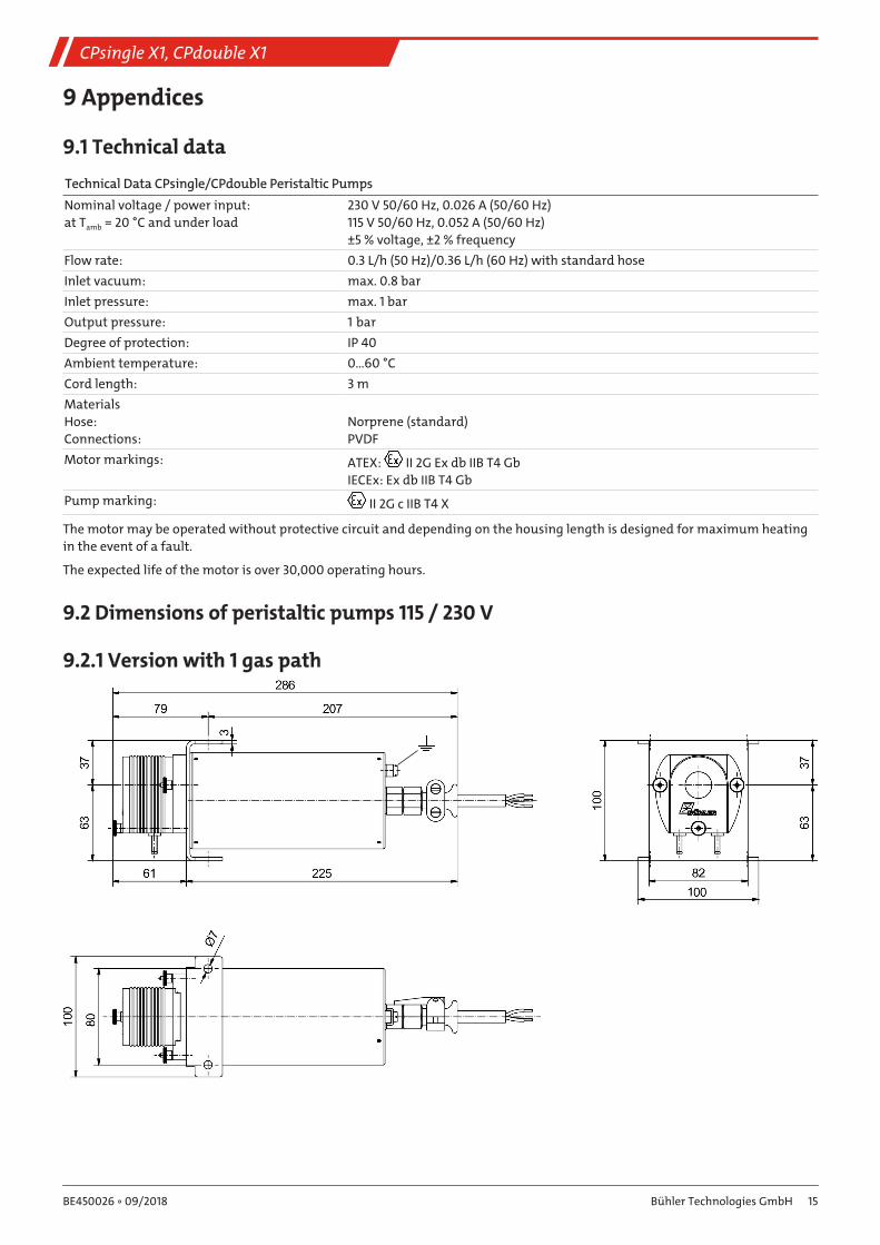
9.2 Dimensions of peristaltic pumps 115 / 230 V
9.2.1 Version with 1 gas path
15Bühler Technologies GmbHBE450026 ◦ 09/2018
CPsingle X1, CPdouble X1
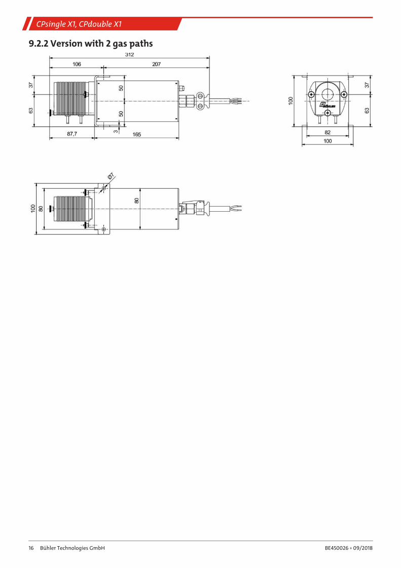
9.2.2 Version with 2 gas paths
16 Bühler Technologies GmbH BE450026 ◦ 09/2018
CPsingle X1, CPdouble X1
10 Attached documents– Certificate IECEx IBE 17.0019
– Type Examination Certificate IBExU17ATEX1008
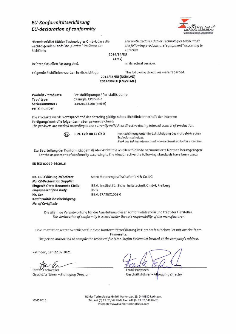
– Declaration of Conformity KX450016
– RMA - Decontamination Statement
17Bühler Technologies GmbHBE450026 ◦ 09/2018
IBExU Institut für Sicherheitstechnik GmbH An-Institut der TU Bergakademie Freiberg
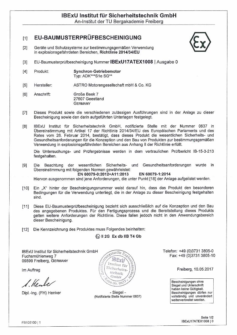
[11 EU-BAUMUSTERPRÜFBESCHEINIGUNG
[2] Geräte und Schutzsysteme zur bestimmungsgemäßen Verwendung in explosionsgefährdeten Bereichen, Richtlinie 2014/34/EU
[3] EU-Baumusterprüfbescheinigung Nummer IBExU17ATEX1008 1 Ausgabe 0
[4] Produkt:
[5] Hersteller:
[6] Anschrift:
Synchron-Getriebemotor Typ: ADK***S1e SG**
ASTRO Motorengesellschaft mbH & Co. KG
Große Beek 7 27607 Geestland GERMANY
[7] Dieses Produkt sowie die verschiedenen zulässigen Ausführungen sind in der Anlage zu dieser Bescheinigung sowie den darin aufgeführten Unterlagen festgelegt.
[8] IBExU Institut für Sicherheitstechnik GmbH, notifizierte Stelle mit der Nummer 0637 in Übereinstimmung mit Artikel 17 der Richtlinie 2014/34/EU des Europäischen Parlaments und des Rates vom 26. Februar 2014, bestätigt, dass dieses Produkt die wesentlichen Sicherheits- und Gesundheitsanforderungen für die Konzeption und den Bau von Produkten zur bestimmungsgemäßen Verwendung in explosionsgefährdeten Bereichen aus Anhang II der Richtlinie erfüllt.
Die Untersuchungs- und Prüfergebnisse werden in dem vertraulichen Prüfbericht IB-15-3-213 festgehalten.
[9] Die Beachtung der wesentlichen Sicherheits- und Gesundheitsanforderungen wurde in Übereinstimmung mit folgenden Normen gewährleistet:
EN 60079-0:2012+A11:2013 EN 60079-1:2014 Hiervon ausgenommen sind jene Anforderungen, die unter Punkt [18] der Anlage aufgelistet werden.
[1 O] Ein „X" hinter der Bescheinigungsnummer weist darauf hin, dass das Produkt den besonderen Bedingungen für die Verwendung unterliegt, die in der Anlage zu dieser Bescheinigung festgehalten sind.
[11] Diese EU-Baumusterprüfbescheinigung bezieht sich ausschließlich auf die Konzeption und den Bau des angegebenen Produktes. Für den Fertigungsprozess und die Bereitstellung dieses Produkts gelten weitere Anforderungen der Richtlinie. Diese fallen jedoch nicht in den Anwendungsbereich dieser Bescheinigung.
[12] Die Kennzeichnung des Produktes muss Folgendes beinhalten:
®112G ExdbllBT4Gb
Dipl.-Ing. (FH) Henker
FB10610011
- Siegel -(Notifizierte Stelle Nummer 0637)
Telefon: +49 (0)3731 3805-0 Fax: +49 (0)3731 3805-10
Freiberg, 10.05.2017
Bescheinigungen ohne Siegel und Unterschrift haben keine Gültigkeit. Bescheinigungen dürfen nur vollständig und unverändert weiterverbreitet werden.
Seite 1/2 IBExU17ATEX1008 I 0
IBExU Institut für Sicherheitstechnik GmbH An-Institut der TU Bergakademie Freiberg
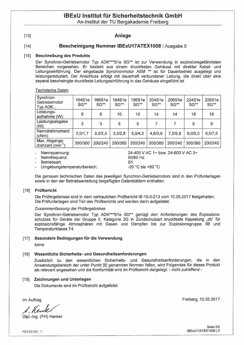
[13] Anlage
[14] Bescheinigung Nummer IBExU17ATEX1008 1 Ausgabe O
[15] Beschreibung des Produkts
Der Synchron-Getriebemotor Typ ADK***S1 e SG** ist zur Verwendung in explosionsgefährdeten Bereichen vorgesehen. Er besteht aus einem druckfesten Gehäuse mit direkter Kabel- und Leitungseinführung. Der eingebaute Synchronmotor ASM ** ist für Dauerbetrieb ausgelegt und leistungsreduziert. Der Anschluss erfolgt mit dauerhaft verbundener Leitung, die direkt über eine separat bescheinigte druckfeste Leitungseinführung in das Gehäuse eingeführt ist.
Technische Daten
Synchron-164S1e 166S1e 184S1e Getriebemotor
SG** SG** SG** TypADK .. . Leistungs-
6 6 10 aufnahme (W): Leistungsabgabe
3 3 5 (W): Nenndrehmoment
2,0/1 ,7 3,0/2,5 3,3/2,8 (cNm): Max. Abgangs-drehzahl (min-\ 300/360 200/240 300/360
- Nennspannung: - Nennfrequenz: - Betriebsart: - Umgebungstemperaturbereich:
186S1e 204S1e 206S1e 224S1e SG** SG** SG** SG**
10 14 14 18
5 7 7 9
5,0/4,2 4,6/3,9 7,0/5,8 6,0/5,0
200/240 300/360 200/240 300/360
24-400 V AC 1- bzw. 24-600 V AC 3-50/60 Hz S1 -20 °C bis +60 °C
226S1e SG**
18
9
9,0/7,5
200/240
Die genauen technischen Daten des jeweiligen Synchron-Getriebemotors sind in den Prüfunterlagen sowie in den der Betriebsanleitung beigefügten Datenblättern enthalten.
[16] Prüfbericht
Die Prüfergebnisse sind in dem vertraulichen Prüfbericht IB-15-3-213 vom 10.05.2017 festgehalten. Die Prüfunterlagen sind Teil des Prüfberichts und werden darin aufgelistet.
Zusammenfassung der Prüfergebnisse
Der Synchron-Getriebemotor Typ ADK***S1e SG** genügt den Anforderungen des Explosionsschutzes für Geräte der Gruppe II , Kategorie 2G in Zündschutzart druckfeste Kapselung „db" für explosionsfähige Atmosphären mit Gasen und Dämpfen bis zur Explosionsgruppe 118 und Temperaturklasse T4.
[17] Besondere Bedingungen für die Verwendung
keine
[18] Wesentliche Sicherheits- und Gesundheitsanforderungen
Zusätzlich zu den wesentlichen Sicherheits- und Gesundheitsanforderungen, die in den Anwendungsbereich der unter Punkt [9] genannten Normen fallen, wird Folgendes für dieses Produkt als relevant angesehen und die Konformität wird im Prüfbericht dargelegt: - nicht zutreffend -
[19] Zeichnungen und Unterlagen
Die Dokumente sind im Prüfbericht aufgelistet.
Im Auftrag
/~ Dipl.-Ing. (FH) Henker
FB 106100 11
Freiberg, 10.05.2017
Seite 2/2 1BExU17ATEX1008 I 0
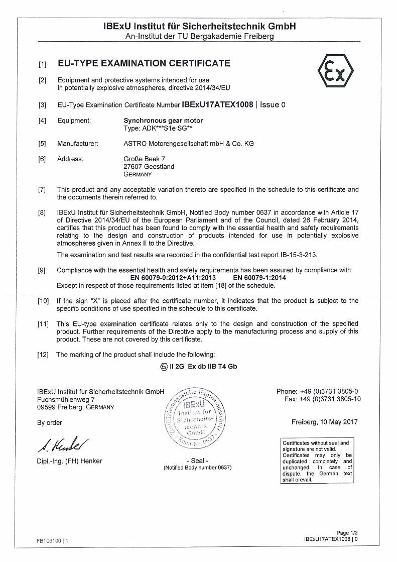
IBExU Institut für Sicherheitstechnik GmbH An-Institut der TU Bergakademie Freiberg
[1J EU-TYPE EXAMINATION CERTIFICATE
[2] Equipment and protective systems intended for use in potentially explosive atmospheres, directive 2014/34/EU
[3] EU-Type Examination Certificate Number IBExU17 ATEX1008 l lssue 0
[4] Equipment:
[5] Manufacturer:
[6] Address:
Synchronous gear motor Type: ADK***S1 e SG**
ASTRO Motorengesellschaft mbH & Co. KG
Große Beek 7 27607 Geestland GERMANY
[7] This product and any acceptable variation thereto are specified in the schedule to this certificate and the documents therein referred to.
[8] IBExU Institut für Sicherheitstechnik GmbH, Notified Body number 0637 in accordance with Article 17 of Directive 2014/34/EU of the European Parliament and of the Council, dated 26 February 2014, certifies that this product has been found to comply with the essential health and safety requirements relating to the design and construction of products intended for use in potentially explosive atmospheres given in Annex II to the Directive.
The examination and test results are recorded in the confidential test report I B-15-3-213.
[9] Compliance with the essential health and safety requirements has been assured by compliance with: EN 60079-0:2012+A11:2013 EN 60079-1:2014
Except in respect of those requirements listed at item [18] of the schedule.
[1 O] lf the sign "X" is placed after the certificate number, it indicates that the product is subject to the specific conditions of use specified in the schedule to this certificate.
[11] This EU-type examination certificate relates only to the design and construction of the specified product. Further requirements of the Directive apply to the manufacturing process and supply of this product. These are not covered by this certificate.
[12] The marking of the product shall include the following:
~112G ExdbllBT4Gb
IBExU Institut für Sicherheitstechnik GmbH Fuchsmühlenweg 7 09599 Freiberg, GERMANY
By order
Dipl.-Ing. (FH) Henker - Seal -(Notified Body number 0637)
FB106100 11
Phone: +49 (0)3731 3805-0 Fax: +49 (0)3731 3805-10
Freiberg, 10 May 2017
Certificates without seal and signature are not valid. Certificates may only be duplicated completely and unchanged. In case of dispute, the German text shall orevail.
Page 1/2 IBExU17ATEX1008 I 0
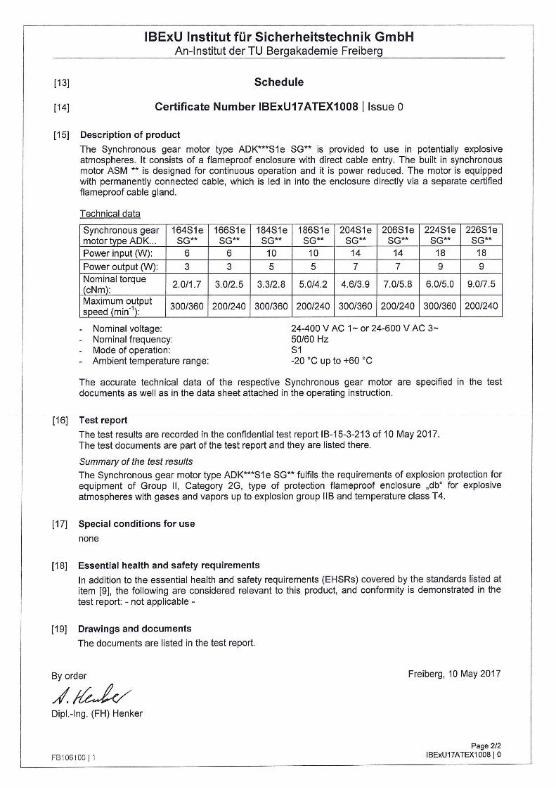
IBExU Institut für Sicherheitstechnik GmbH An-Institut der TU Bergakademie Freiberg
[13] Schedule
[14] Certificate Number IBExU17ATEX1008 l lssue o
[15] Description of product
The Synchronous gear motor type ADK***S1e SG** is provided to use in potentially explosive atmospheres. lt consists of a flameproof enclosure with direct cable entry. The built in synchronous motor ASM ** is designed for continuous operation and it is power reduced. The motor is equipped with permanently connected cable, which is led in into the enclosure directly via a separate certified flameproof cable gland.
Technical data
Synchronous gear 164S1e 166S1e 184S1e motor type AOK .. . SG** SG** SG** Power input (W): 6 6 10
Power output (W): 3 3 5 Nominal torque
2.0/1 .7 3.0/2.5 3.3/2.8 (cNm): Maximum output speed (min·\ 300/360 200/240 300/360
- Nominal voltage: - Nominal frequency: - Mode of operation: - Ambient temperature range:
186S1e 204S1e 206S1e 224S1e SG** SG** SG** SG**
10 14 14 18
5 7 7 9
5.0/4.2 4.6/3.9 7.0/5.8 6.0/5.0
200/240 300/360 200/240 300/360
24-400 V AC 1- or 24-600 V AC 3-50/60 Hz S1 -20 °C up to +60 °C
226S1e SG**
18
9
9.0/7.5
200/240
The accurate techn ical data of the respective Synchronous gear motor are specified in the test documents as weil as in the data sheet attached in the operating instruction.
[16] Testreport
The test results are recorded in the confidential test report 18-15-3-213 of 10 May 2017. The test documents are part of the test report and they are listed there.
Summary of the test results
The Synchronous gear motor type ADK***S1 e SG** fulfils the requirements of explosion protection for equipment of Group II, Category 2G, type of protection flameproof enclosure „db" for explosive atmospheres with gases and vapors up to explosion group 118 and temperature class T4.
[17] Special conditions for use
none
[18] Essential health and safety requirements
In addition to the essential health and safety requirements (EHSRs) covered by the standards listed at item [9], the following are considered relevant to this product, and conformity is demonstrated in the test report: - not applicable -
[19] Drawings and documents
The documents are listed in the test report.
8y order
~~ Dipl.-Ing. (FH) Henker
FB1 06100 j 1
Freiberg, 10 May 2017
Page 2/2 1BExU17ATEX1008 j 0
Related Documents