Copyright © 2009 COMSOL. Redistribution is not allowed without permission from COMSOL. Introductory tutorial to the RF Module: Periodic Problems & Diffraction Gratings 0 0,25 0,5 0,75 1 0 10 20 30 40 50 60 70 80 90

Welcome message from author
This document is posted to help you gain knowledge. Please leave a comment to let me know what you think about it! Share it to your friends and learn new things together.
Transcript

Copyright © 2009 COMSOL. Redistribution is not allowed without permission from COMSOL.
Introductory tutorial to the RF Module:
Periodic Problems & Diffraction Gratings
0
0,25
0,5
0,75
1
0 10 20 30 40 50 60 70 80 90

Copyright © 2009 COMSOL. Redistribution is not allowed without permission from COMSOL.
First exercise: Plane wave coming in at an angle
Pincident
Preflected
Ptransmitted
1
TR
P
PT
P
PR
incident
dtransmitte
incident
reflectedConsider two
polarizations of
incident light:
TE, Electric field is
perpendicular to
the plane
TM, Magnetic field
is perpendicular to
the plane
boundary
P HEn Re21

Copyright © 2009 COMSOL. Redistribution is not allowed without permission from COMSOL.
Sketch the domains
Use the 2D Hybrid
Modes formulation
Sketch five stacked
rectangles, each 2x1
microns
Join the top two into a
single composite object
Join the bottom three into
a single composite object
Go to:
Draw… Use Assembly…
Set these
three to a
refractive
index of n=1
n=1.5

Copyright © 2009 COMSOL. Redistribution is not allowed without permission from COMSOL.
Set up a parametric study on incident angle
2k
sinkkx
coskky
nm1550
Set up global
expressions for
the k-vector and
components as a
function of
incident angle

Copyright © 2009 COMSOL. Redistribution is not allowed without permission from COMSOL.
Use Floquet boundary condition on the sides
Leave all interior boundaries at the default, continuity
Set all other boundaries to PMCPMC
PMC
PMC
PMC

Copyright © 2009 COMSOL. Redistribution is not allowed without permission from COMSOL.
There is also a “Boundary Pair” at the
boundaries between the two objects
Set the boundary pair to be the Port
boundary condition, and set an input power

Copyright © 2009 COMSOL. Redistribution is not allowed without permission from COMSOL.
Use an analytic expression for a plane wave
Specify either a TE or TM mode, and use the analytic
expression for a plane wave at an angle to a line:
exp(-i*kx*x)Also, enter the propagation constant normal to the boundary:
ky

Copyright © 2009 COMSOL. Redistribution is not allowed without permission from COMSOL.
The pair condition applies the incident field
to only one side of the pair
The source boundary is
colored cyan by default
The destination boundary
is colored purple by default
An incident field can be
applied at the source
boundary, and will only
propagate in one direction
into the domain, where it
may reflect back
Any reflected wave will
pass back through the pair
boundary unimpeded

Copyright © 2009 COMSOL. Redistribution is not allowed without permission from COMSOL.
When using Assembly mode, the mesh
may be non-congruent, try to avoid this
Assembly meshing allows
elements to be non-congruent.
Assembly meshes add extra
equations “behind the scenes”
that balance the flux between
the adjacent elements.
In 2D, you must have at least eight
elements per wavelength in the media
In 3D, use five elements per λlocal

Copyright © 2009 COMSOL. Redistribution is not allowed without permission from COMSOL.
Using PML’s absorbing in the y-direction to
absorb the wave
Air
Air
Air+PML
Glass+PML
Glass
Incident + Reflected Wave
Transmitted Wave
Wave absorbed in PML
Wave absorbed in PML
Reflected Wave Only
The use of PML’s means that the top and bottom BC’s don’t matter
Boundary Pair
Copyright © 2009 COMSOL. Redistribution is not allowed without permission from COMSOL.
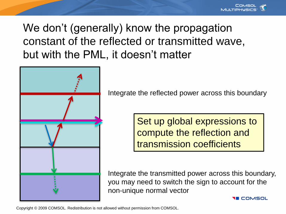
We don’t (generally) know the propagation
constant of the reflected or transmitted wave,
but with the PML, it doesn’t matter
Integrate the reflected power across this boundary
Integrate the transmitted power across this boundary,
you may need to switch the sign to account for the
non-unique normal vector
Set up global expressions to
compute the reflection and
transmission coefficients

Copyright © 2009 COMSOL. Redistribution is not allowed without permission from COMSOL.
When solving periodic problems, make sure
to change the solver settings as shown:
Solve for
incident angles
from 0-90° and
for both TE and
TM excitations,
which you have
to switch on the
Port tab

Copyright © 2009 COMSOL. Redistribution is not allowed without permission from COMSOL.
Results…
0
0,25
0,5
0,75
1
0 10 20 30 40 50 60 70 80 90
Reflection
Angle
Brewster’s
Angle
Accuracy is
degraded at
grazing
incidence
TE or s-polarized
TM or p-polarized

Copyright © 2009 COMSOL. Redistribution is not allowed without permission from COMSOL.
At grazing incidence, accuracy is degraded
0
0,2
0,4
0,6
0,8
1
1,2
0 10 20 30 40 50 60 70 80 90
Angle
Plot reflected plus transmitted power,
should equal applied power, P0=1
If desired, this can
be reduced by
filling the PML with
more elements

Copyright © 2009 COMSOL. Redistribution is not allowed without permission from COMSOL.
Modeling in 3D…Same solver settings…
Same material properties…
Same PML’s…
Same periodic boundary conditions…
Easier to consider polarizations separately…
Different Port excitations…
New boundary conditions…
Special meshing techniques…

Copyright © 2009 COMSOL. Redistribution is not allowed without permission from COMSOL.
Build two models, one TE, on TM
The TM case is when the H-field is
parallel to the boundary at which the
excitation is applied, the red face.
In the TM case, all the blue boundaries
must be PMC, which represents
symmetry.
The TE case is the opposite, when the
E-field is parallel to the excitation
boundary, in this case, the blue faces
must all be PEC.
TM waveE
H
TE waveH
E

Copyright © 2009 COMSOL. Redistribution is not allowed without permission from COMSOL.
Port mode conditions for the TM case

Copyright © 2009 COMSOL. Redistribution is not allowed without permission from COMSOL.
Port mode conditions for the TE case

Copyright © 2009 COMSOL. Redistribution is not allowed without permission from COMSOL.
Meshing strategies…
1) Mesh the faces 2) Sweep the volumes
3) Sweep the PML’s 4) Can also convert
a brick mesh to tets
Use five elements per λlocal

Copyright © 2009 COMSOL. Redistribution is not allowed without permission from COMSOL.
When using brick elements, recall that error
is governed by distance between the nodes
A
B
A
B
Triangular meshes require less memory
and time, since there is less connectivity
In 3D, tetrahedral elements have better
convergence properties using the
iterative solvers, but this does not matter
much for direct solvers.

Copyright © 2009 COMSOL. Redistribution is not allowed without permission from COMSOL.
Results…Arrows: E-field
Colors: H-field
s-polarized (TE) p-polarized (TM)
Again, accuracy is reduced at grazing incidence

Copyright © 2009 COMSOL. Redistribution is not allowed without permission from COMSOL.
Diffraction gratings and periodic structures
Same solver settings…
Same material properties…
Same PML’s…
Same periodic boundary conditions…
Same excitation…
Must use interactive meshing to get a good
mesh on the part:
Copy the mesh for periodic faces
Copy the mesh for identity pair faces
Use about five elements per wavelength
Use five elements through the PML
Use swept meshing as much as possible
Use Convert to Tet Mesh
Related Documents


![[PPT]Diffraction gratings - Welcome | Biomedical Optics …bol.egr.uh.edu/.../bol/files/files/Diffraction_gratings.ppt · Web viewDiffraction gratings By M. Ravi Kiran Introduction](https://static.cupdf.com/doc/110x72/5ac864db7f8b9a6b578c1399/pptdiffraction-gratings-welcome-biomedical-optics-bolegruhedubolfilesfilesdiffraction.jpg)