Period Furniture Details
Oct 24, 2015
Periods of Furniture
Welcome message from author
This document is posted to help you gain knowledge. Please leave a comment to let me know what you think about it! Share it to your friends and learn new things together.
Transcript


Period Furniture Details


Text © 2003 by Lonnie Bird
Photographs © 2003 by The Taunton Press, Inc .
Illu strations © 2003 by The Taunton Press, Inc.
All rights reserved.
ITI~~,:::~~~~~:~~~"~ .The Taunton Press, Inc., 63 South Main Street, PO Box 5506, Newtown, CT 06470-5506
e-mail: tp@taun ton.com
Di stributed by Pub lishers Group We st
D ESIGN: Lori Wendin
LAYOUT: Susan Lampe-Wilson
I LLUSTRATOR: Mario Ferro
PH OTOGRAPHER: Lonnie Bird
LIBRARY OF CONGRESS CATALOGING-IN-PUBLICATION DATA:
Bird, Lonnie.
Taunton's complete illustrated guide to period furniture details /Author, Lonnie Bird.
p. cm.
Includes index.
ISBN 1-56158-590-4
1. Furniture making--Amateurs' manuals. 2. Furniture,
Colonial-- United States--Reproduction. 3. Furniture --United
States--H istory-- 18th century. 4. Furniture--United
States-- Reproduction. I. Taunt on Press. II. Titl e.
TT195 .B573 2003684.1'04'097309033--dc21
2003005688
Printed in the United States of America
10 9 8 7 6 5 4 3 2 1
About Your Safety: Working with wood is inherently dangerous. Using hand or power tools
improperly or ignoring safety practices can lead to permanent injury or even death . Don't try to
perform operations you learn about here (or elsewhere) unless you're certain they are safe for
you . If something about an operation doesn't feel right, don 't do it. Look for another way. We
want you to enjoy the craft, so please keep safety foremost in your mind whenever you 're in
the shop.

To my parents, Lee and Pat Bird.
Acknowledgments
W riting a book is a team effort that requires the ideas,
support, and work of many people. Through this work, new
friendships are often forged and old friendships are deepened. With thi s
in mind, I want to say thanks to the many people who helped me with
this project:
Helen Albert ofThe Taunton Press, for her patience and words of
encouragement. Jason Bennett, woodworker, friend, and patient stand-in,
for many of the photos in this book.
Most of all, I want to thank my wife and best friend, Linda. Without
her love, patience, and hard work, this book would not have been possible.

ContentsIntroduction · 3
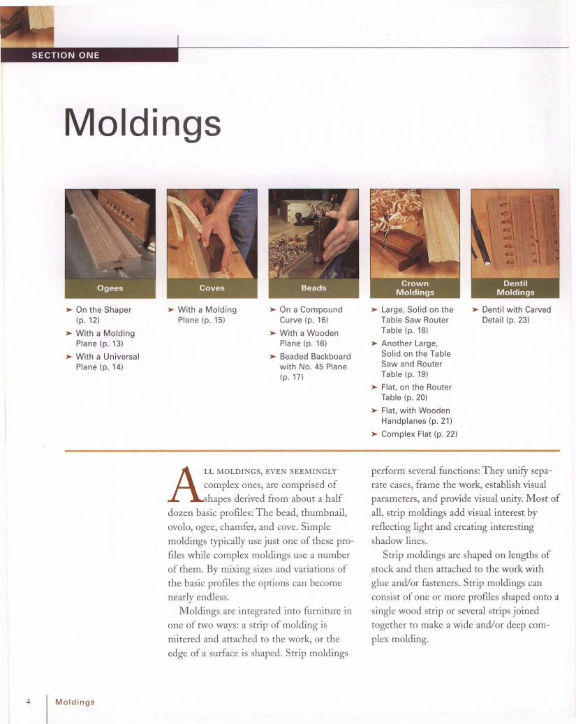
SECTION 1 Moldings · 4
12 Ogees 15 Coves 16 Beads 18 CrownMoldings
23 DentilMoldings
SECTION 2 Legs · 24
27 Tapers 28 Knee Blocks 34 Cabriole Leg

SECTION 3 Tabletops · 36
38 Scalloped Top 39 Dished Top
SECTION 4 Feet · 42
41 Rule Joints
44 Pad Foot 45 Trifid Foot 47 Ball and Claw 50 Flat BaseFoot
52 Ogee Feet
SECTION 5 Bedposts · 56
59 Bedposts

SECTION 6 Chairs · 63
66 Splats 70 Arm andPost
75 Chair Legs 79 Chair Shoe 80 Side Rails
SECTION 7 Casework · 85
94 Dovetails 97 TemplateShapedComponents
100 GooseneckMolding
106 ArchedMolding
107 Rosettes
2
109 Finials
Index · 137
118 Doors 127 Flutes andReeds
134Base andCapitalMolding
136 Candle-Slide

Introduction
Furniture from 18th-century America
continues to be among the most
popular styles of all time. While
other forms of furniture come into
style and soon appear dated, period furniture
continues as a best-selling classic.
And for good reason-period furniture is
rich with detail. It was produced during atime when there was a broad separation
between classes of people. Those with
means, just as with people today, sought
ways to display their wealth and status in
society. One of the primary ways to display
opulence in the eighteenth century was
through finely crafted furniture. In large,
wealthy cities, such as Philadelphia, Boston,
and Newport, Rhode Island, furnituremakers
crafted highly developed furniture artforms.
Embellishment became the norm as artisans
pierced, carved, sculpted, inlaid, and gilded
what is recognized today as some of the
finest examples of furniture ever produced.
As a furnituremaker for over twenty years,
I enjoy the challenge of reproducingAmerican period furniture both for its level
of technical difficulty as well as its timeless
beauty. As you study, draw, and reproduce
these classic examples of Americana, you
can't help but to be immensely impressed
with the period craftsman's sense of design
and proportion, as well as his tremendous
skill with a few relatively simple tools.
As a woodworker, if you're not accus
tomed to using hand tools, then I encourage
you to begin by accumulating the essential
edge tools such as planes, chisels, and a
dovetail saw and enjoying learning to use
them. Furniture produced entirely with
machines is void of the fine details that
define period furniture. Quite simply,
machines for all their sophistication can't
duplicate what's created by a trained eye and
a skillful hand. In other words, while it is
acceptable and desirable to use machines to
saw curves, shape moldings, and even cut
some types ofjoints, hand tools are still
required for many of the details. In the
process you'll experience the delight of cut
ting a dovetail by hand and hearing the
unique sound of a sharp plane as it slices the
surface of a board.
No book or even several volumes of books
can contain the wealth of furniture details
created by America's colonial craftsmen. But,
it is my hope that this book will inspire you
to deeper study and appreciation of period
furniture, and, most importantly, to develop
your skill in building it.
3
Moldings
~ On the Shaper(p.12)
~ With a MoldingPlane (p. 13)
~ With a UniversalPlane (p. 14)
~ With a MoldingPlane (p. 15)
~ On a CompoundCurve (p. 16)
~ With a WoodenPlane (p. 16)
~ Beaded Backboardwith No. 45 Plane(p.17)
~ Large, Solid on theTable Saw RouterTable (p. 18)
~ Another Large,Solid on the TableSaw and RouterTable (p. 19)
~ Flat, on the RouterTable (p. 20)
~ Flat, with WoodenHandplanes (p. 21)
~ Complex Flat (p. 22)
~ Denti l wi th CarvedDetail (p. 23)
ALL MOLDINGS, EVEN SEEMINGLY
complex ones, are comprised of
shapes derived from about a half
dozen basic profiles: The bead, thumbnail,
ovolo, ogee, chamfer, and cove. Simple
moldings typically use just one of these profiles while complex moldings use a number
of them. By mixing sizes and variations of
the basic profiles the options can becomenearly endle ss.
Moldings are integrated into furniture inone of two ways: a strip of molding is
mitered and attached to the work, or the
edge of a surface is shaped. Strip moldings
4 Moldings
perform several functions: They unify sepa
rate cases, frame the work, establish visualparameters, and provide visual unity. Most of
all, strip moldings add visual interest by
reflecting light and creating interestingshadow lines.
Strip moldings are shaped on lengths of
stock and then attached to the work withglue and/or fasteners . Strip moldings can
consist of one or more profiles shaped onto asingle wood strip or several strips joined
together to make a wide and/or deep com
plex molding.

Waistmoldingvisuallyseparatesupperandlower cases.
Crownmolding
k moldings detail.
edpilasterhasizescal lines.
bna il edgeespanels.
--- Base capprovidestransitionbetweencabinetand foot.
MOLDINGS ON A CORNER CABINET
]-~ r-; :=';:=:::
~~;:::= Nee
add
edge Vs
---..... r'--- Flut- emp
verti
IT
~ ~~ I
~ I ,
~~
~I
~ ,,~I~ ~ I~~7
/~f- Thum
Vfram
IT
== I~ ~ I
== I-.L
I-r
Ovoloframeglasslight.
Attaching moldingsParallel strips such as those that wrap
around a table edge must be of the exact
same length for the miter to fit. Use a stop
on the miter saw for exact cuts.
When fitting molding to casework , miter
the front strip first, and then the returns or
side strips. If adjustments need to be made
for a precise fit they can be made to the
return s. Afterwards the ends of the returns
are cut ninety degrees to be flush with the
caseback.
When attaching strip molding, remember
to allow for cross-grain, seasonal wood
movement. Small moldings can be effective
ly fastened with brads, which are set below
the wood surface. As the wood moves the
soft brads will flex. For large moldings such
as a crown molding on casework it works
well to fasten the molding with screws from
the inside of the case. Slot the holes in the
case for the screws to slide as the case
expands and contracts. Always use glue in
the miter joints of moldings; it keeps the
joint closed tight through the years.
Stock selection for moldingsSelect straight-grain stock when making
strip moldings to prevent tearout when
using handtools such as planes and scratch
stock; straight-grain stock will produce less
tearout. When using machines it 's safer to
shape a wide board and rip the molding free
afterward s. This method will position your
hands a safe distance from the cutter or bit.
If you select straight-grained stock the strips
will be less likely to distort when you rip
them free.
Moldings I 5

BASIC MOLDING PROFILES
~ MAKE A LITTLE EXTRA MOLDINGUsing handtools to createmoldingsUsing handtools is quiet work and for periodprojects you get the tool marks and slightimperfections that lend an authentic look.M olding planes were once made in an amazing variety of profiles and can be found atflea markets or in antique shops.
The so-called universal plane, the Stanley
#55, was developed about 100 years ago to
replace a multitude of wooden planes.
For small moldings, a scratchstock can be
used. A scratchstock is simply a scraper with
a profile. By pushing the tool across the
wood surface a molding profile is produced.
Why use a scratchstock instead of a router?
There are several reasons. A scratchstock can
shape tiny profiles that a router can't. Also, a
scratchstock can easily shape a profile along
a freeform curve. And you can easily cus
tomi ze the shape to suite your design
requirements.
The versatile beadThere's probably not a more versatile mold
ing profile than the bead. A bead is a semi
circular or semi-elliptical profile. It can be
shaped flush along the edge of a table apron
or proud around the perimeter of a drawer
front. Used along the edge of backboards in
casework the bead will embellish the back
Making a scratchstockThese days you can buy a scratchstock butit's just as easy to make your own. You canshape a scratchstock from a wood block oryou can use an old wooden marking gauge.Pieces of an old handsaw work well for theblade . To shape the profile into the blade Iuse small files of various shapes.
Ogee
Chamfer
Reverse agee
Cove
Ovalo
Thumbna il
C QUirk
~/ ///2Quirk bead Astragal J
~rZd)
A little extra molding is always useful. If you run short, it
w ill match the grain and profi le exactly. If you do it later, you 'll
have to set up your machinery again and it has to be spot on to
match . Always save a short section of molding when the job is
complete as reference sample.
6 Moldings

while hiding the expansion joint between
the boards. Beads are easily shaped with a
router, plane, hand beader, or a scratchstock.
Undoubtedly it's this versatility and ease of
use that has made the bead so popular for
centuries. Next time you need to soften a
hard edge or add a bit of decoration remem
ber this simple, versatile profile.
When shaping beads, remember that you
need to get to the full depth of the cutter's
profile to achieve the right shape. Beads that
aren't cut to full depth can appear flattened
on one or more sides.
Complex moldingsComplex moldings are combinations of two
or more simple profiles. They are used when
a more drama tic or formal look is desired. A
typical example of a complex molding is the
MAKING A SCRATCH STOCK
~ Face is rounded tofollow tight contours.
For an applied molding, rip the molded pro
file from the main board on the table saw.
For safety, always use a push stick to feed
the stock.
A simple scratch
can be constructed
by cutting a kerf in a
block of wood.
Shape the fence to a
round to ensure
good contact with
the edge of the
stock.
Old bandsaw blades
make good stratch
stock blades. Small
files are used to
shape the profiles.
Moldings I 7

USES FOR THE VERSATILE BEAD
Table edge
Scribed bead on drawer
tI /
Rail~
Backboard
Cock bead on drawer
~Stile
crown molding on most casework. A typical
crown may consist of a large cove flanked bysmaller profiles such as a thumbnail, bead, or
ogee. As the molding steps upward it alsosteps outward to 'look' down toward the
observer.
Waist moldings on casework are another
example of complex moldings . Chests,clocks, desks and other tall examples of case
work are usually constructed of several cases
or 'boxes.' To unity the separate cases, awaist molding is used at the junction of thecases.
There are three options for making a
complex molding: shaping thin, flat stock
and attaching it to the case at an angle,
shaping thick stock, and shaping and stack
ing strips of simple profiles. You can also usea combination of the methods to create acornice. But first let's discuss each methodindividually.
A SAMPLE OFCOMPLEX MOLDINGS
8 I Moldings
/

COMBINING A FLATCROWN MOLDING WITH
STACKED STRIPS
Flat stock moldingsShaping flat stock and mounting at an angle
is commonly used for architectural crown
moldings . It also works well for furniture. A
flat crown molding is beveled on bottom
edges and applied at an angle. This method
uses thinner stock, yet gives the appearanc e
of depth. The downside is that flat moldings
are difficult to apply; it 's awkward to align
the molding and attach it. Additionally, if
the molding isn't capped off will need to be
supported by triangular glue blocks.
The main advantage to thi s method is
that it avoids using thick stock. To shape
wide, flat stock you'll need a shaper with a
long spindle, molding planes, or a table saw
molding head. Unfortunately, a router can't
reach to shape wide stock.
MOLDINGS ON A CHEST
i\ (Crown molding looks ./downtowardviewer,
~ ~ ~providing a terminusto the chest.
~ ~
~ ~Thumbna il edgeframes drawer.
~~ ~
Moldings I 9
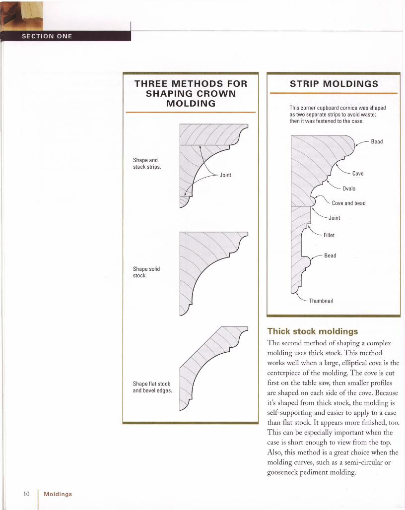
THREE METHODS FORSHAPING CROWN
MOLDING
10 Moldings
Shape andstack strips.
Shape solidstock.
Shape flat stockandbevel edges.
STRIP MOLDINGS
This corner cupboard cornice was shapedastwo separate stripsto avoid waste;then it was fastened to the case.
Bead
'<; Ovalo
f--'-::,..-'--r:'~ Cove and bead
"'-- Joint
'<, Thumbnail
Thick stock moldingsThe second method of shaping a complex
molding uses th ick stock. This method
works well when a large, elliptical cove is the
centerpiece of the molding. The cove is cut
first on the table saw, then smaller profiles
are shaped on each side of the cove. Because
it 's shaped from th ick stock, the molding is
self-supporting and easier to apply to a case
than flat stock. It appears more finished, too.
T his can be especially important when the
case is short enough to view from the top.
Also, th is method is a great choice when the
molding curves, such as a semi-circular or
gooseneck pedim ent molding.

Stacked moldingsThe third method involves stacking strips ofsimple molding profiles to create a wide, dra
matic effect. To avoid using a lot of valuable
stock, the strips can be glued to a secondarywood such as poplar. Once the strips are
stacked the secondary wood will be hidden.
Still anoth er option is to combine themethods described above. The decision of
which method to use is often based uponthe tools and materials at hand.
~ SAFETY GUIDELINES FORCUTTING COMPLEX MOLDINGS
• Make the largest cut first. While the stock has the greatest mass and
resistance to chatter and kickback.
• Make certain that there is sufficient surface area in contact with the table
and fence. Ensuring that there is adequate surface area in contact w ith the
table and fence prevents the possibility of the stock tipping into the cutter
and spoiling the work.
• Position the workpiece to expose the least amount of cutter. When possible
position the cut underneath the stock so that the stock shields your hands.
SHAPING A COMPLEX MOLDING ON THICK STOCK
On complex moldings. eachprofile is shaped separately.Sequence is shown here.
--~OVOIO
I Cove
4 in.
Fillets
Coveand bead
Step 1.Shape coveandbead.
Step 3. Shape coveandfillets.
Fence
Step 2. Invertstockandshape center bead.Fillets are shaped withsquare profile.
Knife
Step 4. Shape ovaloprofile.
Fence
Knife
Fence
Moldings I 11

12 Moldings
Ogee on the ShaperWhen using the shaper, safety is always the
most important issue, even when shaping a
basic profile. Resist any temptation to shape nar
row stock without a power feed or appropriate
jig. Instead, select wide stock, which positions
your hands a safe distance from the cutterhead.
After mounting the cutterhead, check the height
with a combination square (A). Next. adjust the
fence tangent to the smallest cutting circle (8);
then adjust the fence for the smallest possible
opening (C). Next, check the spindle rotation. To
position the cutterhead underneath the stock for
safety requires reversing the spindle to a clock
wise rotation (0). Now add a featherboard for
additional safety and make the cut (E). Afterward ,
rip the molding free on the table saw (F).

Ogee witha Molding PlaneWooden molding planes have been around for
centur ies. Despite the array of power tools avail
able. the woode n plane is still an effective and
enjoyable tool for shaping moldings. Molding
planes are readily available from too l dealers and
flea markets; if you 've never experienced the
pleasure using them , I encourage you to find one
and give it a try.
Stock selection is important; wooden molding
planes are lightweight and work best on straight
grain stock.
Check the iron for sharpness and set it for a light
cut (A). Most asymmetrical profi les (like the ogee
in this example) require that you hold the plane at
an angle in relationship to the wo rk. As an aid in
gauging and maintaining the correct angle. planes
usually have spring lines scribed into the front
end of the plane (8). As you begin each cut. keep
the spring lines parallel to the stock and the
fence in contact w ith the edge of the stock (C).
When you reach the full depth of the profile, the
stop wil l contact the surface of the work and pre
vent the plane from cutti ng farther (0 ).
Moldings I 13

14 IMoldings
Ogee with aUniversal PlaneBegin by selecting the stock . Anything but
the straightest grain makes planing diff icult.
Although soft woods plane easily, you can also
achieve good results with a moderately hard
wood, such as walnut or cherry. The next step
is to set the iron in place and adjust the cutt ing
depth (A).
[ T I P ] Check the iron for sharpness first ;like any chisel or place iron, the edgeshould be smooth and polished.
Adjust the iron w ith the thumbwheel for a light
shaving. Next. set the second skate in position
flush w ith the cutt er or slightly inset (8). Then
slide the fence onto the arms and lock it in place
with the thumbscrews (e). When shaping asym
metrical profiles such as this ogee, it wor ks best
to posit ion the cut inward slightly from the edge
of the stock . This way, the cutter will be trapped
by the stock as you plane, which prevents it from
sliding off of the profile.
Now you're ready to make the cut. Keep the
fence against the stock with one hand and push
the plane firmly with the other (0) . As the shav
ings peel away and the profile is revealed (El.
set the plane's stop to bear against the stock (F).
The stop w ill ensure that all subsequent moldings
are identical in profile depth.

Cove Cut witha Molding PlaneOne of the most common molding planes is
called a round. It's aptly named because of the
semicircular, convex shape of its sale. Hollows,
as the name implies, have a concave sale. Hol
lows and rounds were once produced together
in matching pairs for making moldings-and
they're still useful today.
To make a cove w ith a wooden plane, begin by
laying out the parameters of the cove on the
stock (A). Next, cut a V groove down the length
of the stock. This type of plane does not use a
fence, so the V is required to keep it running in
a straight path.
To cut the profile, make several passes down the
V to establish a cove (8). Then w iden and deepen
the cove until the full prof ile is reached (C).
Moldings I 15

Quirk Bead on aCompound CurveRemember that a compound CUNe is one that
flows in two direct ions simultaneously. Some
furniture components that have compound
curves use simple profiles such as a quirk bead
to provide additional detail and draw the eye to
the flowing lines of the CUNeo
The easiest method for shaping a profile on a
compound curve is to use a scratch stock (A).
See "Making a Scratch Stock" on P: 7.
After bandsaw ing and smooth ing the CUNes,
secure the w orkpiece in a vise. Using the scratch
stock, gently scrape the quirk-bead profile onto
the surface (B). As you work, keep the body of
the scratch stock against the work and tilt it
slightly in the direct ion of the cut (e).
Quirk Bead witha Wooden PlaneWooden quirk-bead planes are sti ll wide ly avail
able, and they're a pleasure to use. Best of all,
the quirk bead has a wide variety of applications .
Begin by selecting clear, straight-grain stock for
planing. Sight down the sole of the plane to set
the plane iron for a light cut (A).
To make the cut, use one hand to keep the fence
of the plane against the stock (notice I've added
a strip a wood to my plane as a fence), w hile
pushing the plane wi th the other hand (Bl. A
quirk bead should have a full, round prof ile. If the
plane comes away from the stock, the bead wi ll
be flat on the side. If you don't plane to the full
depth, the bead will be flat on top . The plane's
built-in stop w ill ride against the stock to prevent
further cutt ing once the full profile is reached.
16 1Moldings

Beaded Backboardwith a No. 45 PlaneYou've probably seen no. 45 planes at your local
flea market (A). Stanley Tools manufactured
them for many years, and so they're quite com
mon. They work wel l for shaping beaded back
boards. The idea behind a beaded backboard is
to hide the expansion joints in a solid-wo od case
back (8).
lj 4-in.-dia. bead with quirk
Backboard
E/ / /Joint allows for Jseasonal expansion .~
After cutt ing the rabbets on all the stock, shape
the bead (E). Follow the same set-up procedure
as you did earlier: set the iron, then the second
skate, and finally the fence. The no. 45 plane is
equipped w ith a special fence for beading that
rides the edge of the rabbet. To make use of it,
you'll f irst need to remove the wood fence (F).
Begin by milling the stock for the backboards. I
prefer to use random-width boards with minor
defects . This allows me to use stock I have on
hand that may not be suitable for more visible
areas.
After milling the stock, cut a rabbet along both
edges of each board. Keep in mind that the rab
bets must be on opposite faces. First, mount a
square cutter in the main body of the plane and
position the second skate flush with the outside
edge of the cutter. Lock the skate in position w ith
the thumbscrews. Now adjust the cutter for a
light cut and lock it in place. Finally, slide the
fence in position on the arms and lock it in place
next to the cutte r (e ). Whi le cutt ing the rabbet,
keep the fence firmly against the stock (0) . As
you reach the full depth of the rabbet on the
first piece, adjust the depth stop to bear against
the work.
Moldings I 17

Step 2.Rip awayexcess ./stock.~
Step 1. Cut coveon the table saw.
Table
Large, Solid CrownMolding on the Table Sawand Router TableThe molding shown here is used as a crow n for
a large case, such as a Connect icut-style tall
chest. But the techn ique, like most in this book,
has broad applications.
Many furnitu re crow n moldings use a deep, ellip
tical cove as the large focal point , w ith smaller,
basic prof iles flanking it. Making the molding
from one piece of solid stoc k ensures continuity
of grain and color and greatly simplifies applica
tion to the casew ork
Begin by drawing the profile full-scale. This
ensures good proportions and allows you to plan
each cut more easily. Next. shape the cove on the
table saw w hile the stock is stil l square (A, B).
Before you begin shaping wi th the router, rip
away the excess stock at the base of the mold
ing. Now turn your attention to the thum bnail
prof ile at the top of the molding. If you have a
shaper, you can invert a roundover cutter (e) ; or
you can use a special inverted router bit, available
from CMT USA. Inc. (0) .
18 I Moldings
1m
"--- Step 2. Shape bead.
Step 1. Shape thumbnailon the router table withan inverted crownmolding bit. __-

Shape the bead next. The tall fence that came
with your router table w ill obstruct the cut.
Instead, use a flat, wide piece of stock. Cut it
the same length as your router table and clamp
it to the top after cutting a small opening for the
bit. Now stand the molding on edge and shape
the bead (El.
There is only one profi le remaining: the small
cove at the base. To cut the cove, you can
use the shaper (F, G) or a corebox bit on the
router table.
II
I
'<, Table
Cut the cove on the shaperwith an inverted cutterhead.
Cove withtable saw
Thumbnail wi thcrown-molding bits
Another Large,Solid Crown Moldingon the Table Saw andRouter TableHere's another example of a solid crown mold
ing. Many design variations can be accomp lished
with the use of different prof iles. This example
uses a large cove flanked by an ogee at the top
and a thumbnail profile at the base (A).
Begin by shaping the large cove on the table saw
(8) and then rip off the excess stock (C).
Next, invert the molding to shape the ogee at the
top (0) . Finally, lay the mold ing on its back to
shape the thumbna il (El.
(This cutter is from the CMT USA. lnc., crown
molding set.)
Moldings I 19

Flat Crown Moldingon the Router TableLike an architectural cornice, this molding is
attached to a case at a 45-degree angle (A).
After milling wide stock for safety, start by shap
ing the cove. I've removed the bearing on the
cove bit to allow it to cut deeper. Shape this pro
file with the stock face down (8). Next, shape the
thumbnail profile at the base of the molding (C).
Now turn the stock on edge and shape the sec
ond thumbnail (0).
Because the back of this molding can be seen
inside the lid, it's necessary to bevel the back cor
ner for refinement. Begin by tilting the table-saw
blade to 45 degrees and lowering the blade so
that it doesn't penetrate the stock thickness.
Now rip a kerf along the back of the molding (E).
Return the blade to 90 degrees and set the
height just above the stock thickness . Position
the fence for the width of the molding and rip
it free (F).
A SAMPLE OF FLATCROWN MOLDINGS
20 I Moldings

Flat Crown Molding withWooden HandplanesWooden handplanes still have a place in the
small shop. Here's a good example: To shape a
wide . flat crown by a machine method. you
would need a large shaper or a molder. Yet you
can easily shape crown moldings with a few
hollow and round planes.
Begin by drawing the crown molding full-size.
Next select clear straight-grain stock for the
molding (A).
The first step in shaping is to saw the fillet that
separates the two profiles. Tilt the sawblade
to 45 degrees and position the fence to align
with the drawing you made earlier. Next. saw
V-grooves to guide the planes (8). Now, shape
the cove that is part of the ogee. Then shape
the cove that is adjacent to the fillet (C).
The final step of the process is to bevel the
edges of the molding to 45 degrees. Simply tilt
the blade and position the fence for this ripping
cut. This completes the crown molding (0) .
Moldings I 21

Shape coveseparate ly; thenglue on bead strip.
II
Complex Flat CrownMoldingMany crown moldings, including the one in this
example, incorporate a large cove flanked by a
small bead at the base (A). With this style of
mo lding, it becomes necessary to shape the
cove and bead separately and join them after
shaping. Otherwise, the bead w ill be cut away
during the cove-shaping process.
Begin by shaping the cove (8). Next, bevel the
edges of the cove strip . First bevel the front
edges (C); then the back edges (D).
Now shape the small secondary molding strip.
Start by shaping the bead (E) and then complete
the strip with the cove (F). Finally, glue the strip
onto the base of the cove (G).
22 IMoldings

-------~--- Drill holes.
The next step is to carve the arch at the top of
each kerf. Finally, drill a small hole above each
kerf to complete the job (E).
Before beginning, it's essential to understand the
importance of accurate spacing on furniture dentil
molding. The miters at each end should fall pre
cisely on the edge of a dentil block instead of at a
space or in the middle of a block. Therefore, the
brad-spacing technique used in the previous
examples isn't effective here. Even the smallest
spacing error is multiplied many times over,
wh ich may affect the location of the blocks at
each end.
Dentil with a Carved Detail
Thus it's best to layout the entire length of dent il
strip wi th dividers (8) and a square (C). After
making the layout, saw each space to the line
(0). It's not nearly as tedious as it sounds,
because you need only a few feet of molding .
Furniture dentil is often more elaborate than
architectu ral dent il. The dent il shown here is a
good example (A). The bottom of the space
between each dentil block is carved with an
arch. Above each arch is a small hole, which
accentuates the arch, adding even greater detail.
The time involved in producing many linear feet
of this dentil for a room is more than most peo
ple are willing to spend. But 7 ft. or so for a
chest isn't enormously time consuming.
Moldings I 23

Legs
~ On the Bandsaw(p.27)
~ Turned Taper (p. 30)
~ Offset Taper (p. 32)
~ Under-the-ApronKnee Blocks (p. 28)
~ Over-the-ApronKnee Blocks (p. 29)
~ Cabriole Leg (p. 34)
24 Legs
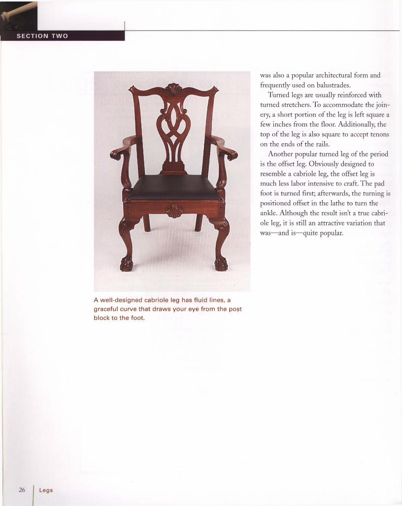
NOTHING SYM BOLIZES 18TH-century
furniture more than the cabriole
leg. It was integrated into every
form of furni ture casework, tables, chairs
even beds.
Cabriole legs exhibit tremendous varia
tion; in fact, furniture historians can often
determine the origin of an antique based
upon the legs and feet. Pad feet are the most
common and easiest to reproduce; its circu
lar form is easily turned on a lath e.
Pennsylvania and D elaware Valley furniture
often feature trifid, or th ree-toed, feet.
Undoubtedly, the most familiar design is the
c1aw-and-ball foot. Because it was so time
consuming to carve, it was a status symbol
for the wealthy.
See "Feet" on P: 42 for information.
Cabriole legs are not difficult to make;
they are essent ially a compound curve which
requires bandsawing two adjacent faces.
However, designing and drawing a leg with
balance, proport ion, and flowing curves can
be quite a challenge . When designing a
cabriole leg, it is always best to begin by
looking at good examples for inspiration and
direction.
Cabriole ProportionsBegin by establishing dimensions for the
knee, post block, ankle, and foot. Knees usu
ally fall within a range of 1/ 2 in. to 27/ 8 in.
T he foot is proportional to the knee or
slightly smaller. Ankles can range in size
from 13/16 in.on a slender leg of a diminutive
tea table to 1/ 2 in. on a bed or large case
piece. T he post block is usually 3/4 in. to 1 in.
smaller than the knee. A post block that is
too small will not allow sufficient room for

Post block
LEG DIAGRAM HEAD
t
t
t
/
I
I
II
\
I- f----
I- f--
\1 -,
I~
t f-- t
lY16 in.JI
L I3h6in.1 7/8 in.
o
-
Leave this area full size forthe lathedrive center. Cut itoff after shaping the leg.
3/8 in. ----. ~I I
'\ \ .......---- >-- Kn ee
V
1 square = 1 in. 2 1/ 4 in.
Bridge to --1'"""--....L
support the r--..~'_+----1--+-_legwhen ~
sawing ~'----L-'\-tJ-+---t--
l-- AnkleI- f---- .......1- 5/16 in. dia.-
I
Mortise7/ 8 in.deep _ :+--+-+----'-t-+-'-"-r-t---+-
Turned legsD uring the early years of the 18th centurybefore most the design details ofWilliamand-Mary furniture dissipated, turn ed legs
were quite common on tables, chairs, and
even casework. Probably the most familiar
form of turned leg from this period is the
ring-and-vase. W idely used on table legs, it
Tapered legsNot all period legs were curved; many
pieces, from simple to refined, feature
tapered legs. In fact, tapered legs were invogue during the Federal Period(1780-1810) and featured contrasting
stringing and delicate inlays.
Tapered legs can be tapered on two, three,
or four sides with the two-s ided taper prob
ably most common. The taper usually begins
immediately below the rail or apron andends at the floor. Typically, the tapered endof the leg is half the width of the leg at the
starting point. T his creates a graceful slender
leg with a small footprint without sacrificing
strength in the post area where the joinery
occurs.
joinery; it can also make the knee appearswollen.
Undoubtedly, the most impor tant part ofa cabriole leg is the graceful "S" curve; the
finest legs have smooth continuous curves
that lead your eye from the post block to the
foot. Stiff, straigh t legs lack appeal and
should be avoided. When designing legs for
a new piece of furniture I'm developing, I' llcarve a prototype and study it from allangles. Only after I'm satisfied with the pro
totype do I begin construction of the piece.
Legs I 25
26
A well -designed cabriole leg has fluid lines, a
graceful curve that draws your eye from the PO$t
block to the foot.
was also a popular architectural form and
frequently used on balustrades.
Turned legs are usually reinforced with
turned stretchers. To accommodate the join
ery, a short portion of the leg is left square a
few inches from the floor. Additionally, the
top of the leg is also square to accept tenons
on the ends of the rails.
Another popular turned leg of the period
is the offset leg. Obviously designed to
resemble a cabriole leg, the offset leg ismuch less labor intensive to craft. The pad
foot is turned first; afterwards, the turning is
positioned offset in the lathe to turn the
ankle . Although the result isn't a true cabri
ole leg, it is still an attractive variation that
was-and is-quite popular.

Line of taper
Taper beginshere.
Notaper onthis face
Next, mount a w ide blade, such as *' in., on the
bandsaw. Using a wide blade greatly reduces the
tendency for the blade to wander in the cut (0) .
Start at the foot and closely follow the layout line
(El. Turn the leg 90 degrees and make the sec
ond cut (F). After all the cuts are made, remove
the saw marks w ith a sharp bench plane (Gl.
Two-Sided Tapered LegFreehand on the BandsawBegin by laying out the taper on the stock (A). To
simplify construction, tapers usually don't extend
into the area of joinery (8). It's best to layout
and cut the leg mortise wh ile the stock is sti ll
square (Cl.
Mortise
Legs I 27

28 Legs
Under-the-ApronKnee Blocks
Knee blocks, sometimes referred to as transition
blocks, visually unite the compound curves of a
cabriole leg with the curves on a rail or apron. For
the under-the-apron type, begin by gluing together
the leg to the rail or apron. Then work the post
block flush with a block plane (A). You can wor k
the inside corner with a chisel (8) and a shoulder
plane (e) .
Next, trace the knee profile onto the knee block
(0) and track the pattern contour on the block
face (E). Bandsawing the knee block requires tap
ing the offcut back in position after the first cut.
After sawing the second cut , glue the knee block
in position (F). Finally, pare the knee block flush
with the surface of the knee (G). The fin ished
knee block (H).

Over-the-ApronKnee Blocks
The process of shaping over-the-apron knee
blocks is similar to the under-apron type . Glue the
leg to the rail or apron. After wor king the post
block flush, trace the knee prof ile (A) and the
knee pattern onto the block (8) . Next bandsaw
the face contour and glue the knee block to the
backing board for carving (e) . Heavy paper in the
glue joint w ill allow you to pry the block up later.
Carefully carve the face of the block with a 1 in.
#2 gouge. As you carve, fol low the layout line
that you traced from the knee. After gluing the
knee block to the apron, blend the surfaces wi th
the knee (0) . The finished knee block (E).
Legs I 29

Sq uare Turning a Tapered LegBecause the leg used in this example has a
square section for joinery, it's important to center
the stock accurately in the lathe (A). Otherwise,
the turned portion will be offset from the square
portion .
Begin by turning the pommel with the point of
a skew (B). First nick the corner; then cut from
the right and the left. The pommel is complete
when the cut from the skew runs the entire
circumference (C).
Next, turn the leg round with a roughing gouge
(0). Use the corner of the gouge to cut in the
area adjacent to the pommel (E).
1'/4 in.
L"". ;01
11/ain. 19/16 in.
30 \ Leg,

Once the leg is round, layout the turning w ith a
story stick (F). Next. shape the bead adjacent to
the pomme l. You'll need to use a skew to shape
the bead in this tight spot.
The next step is to turn the cove and bead. Begin
by cutt ing a fillet adjacent to the bead location
(G). Then use a skew to remove the extra stock
at the taper (H). Now, use a spindle gouge to
shape the cove (I). Use a spring caliper to mea
sure the final diameter of the cove. Most of the
taper can be shaped w ith a gouge, but you'll
need to use a skew to complete the taper as it
approaches the bead. Finally, turn the bead and
cove at the foot (J). Then sand the turn ing lightly
to smooth it (K).
Legs I 31

0--------- Adjust to suit.----- - --- Turning an Offset Leg
Begin by locating the true center of the stock on
each end of the wor kpiece; then locate the cen
ter for the ankle (B). Next, mount the leg in the
lathe w ith the foot at the tailstock. This will avoid
the risk of striking the drive center as you turn
the foot. Now, turn the pomme l w ith the point of
a skew. First nick the corner (C); then cut from
the left (0) and the right (E) until the point of the
skew scores the entire perimeter (F). Afte rward,
turn the leg round below the pommel with a
roughing gouge (G). Then mark a line to indicate
the top of the foot (H). Don't turn the foot yet;
otherwise you will cut away the center needed
for turning the ankle.
The next step is to offset the stock in the lathe
(I). Most of the offset occurs at the foot end of
the stock. However, it's important to slightly off
set the opposite end as wel l. Check the offset for
accuracy before turning. When offset correctly,
the two separate axes w ill converge at the pom
mel. Turn on the lathe and watch the spinning
"ghost" of the leg to see where the axes con
verge. If necessary, stop the lathe and reposition
the leg at the top slightly. Don't adjust the center
location at the foot-otherwise you'll change the
diameter of the ankle.
The simple, yet attractive , offset leg is most
often used on small tables. Unlike a true cabrioIe
leg, this leg is turned in entirety, whi ch makes it
quick to produce. To make the leg, first turn the
pommel with the stock centered . Then offset
the turning in the lathe to turn the ankle and the
taper of the leg. Finally, return the leg to center
and turn the foot. Because two sets of points
are used, the turning will have two axes. For the
leg to have the correct appearance the axes
should converge at the pomme l (A).
TopView
(>Adi u st to~fit rail.
Axes intersect here.
0VBottomView
32 I Legs

The next step is to turn the ankle. Before you begin,
check the location of the tool rest. Position the rest
as close as possible for the best support of the tool,
but spin the work by hand to ensure that it clears
the rest.
During the initial turning of the ankle, the gouge
makes contact with the stock only once each revolu
tion. Because of this, take light cuts to avoid having
the stock grab the tool. Starting near the top of the
foot, cut downward toward the ankle with a spindle
gouge (J). Start with the gouge on edge, and roll it
as you approach the bottom of the foot (K). Take
several light cuts and then check the ankle size.
When the cut encompasses the full perimeter, the
ankle is complete.
Next, turn the tapered port ion of the leg (L). If the
leg vibrates, try wrapp ing one hand around it for
support (M). The amount of stock to be removed
diminishes as the taper ends at the pommel (N).
Now, sand and smooth the taper before turning the
foot (0).
To turn the foot. first reposition the turning on the
true centers. Then turn the pad to diameter with a
parting tool (P). Next, round the foot profile with a
spindle gouge (a). The technique is the same as
that used when turning a bead. Sand the foot lightly
to complete the turning (R).
& WARNING Supporting slender
stock with your hand works extremely
well, especially on a taper where it may
be difficult to mount a steady rest. But
avoid wearing jewelry or long sleeves,
and keep your fingers away from the
tool rest where they may be pinched.
Legs I 33

To avoid backing out of a long curve, begin saw
ing by making the short, straight cuts at the top
of the knee and post block (e). Then saw the
curves at the front (0 ) and back of the leg (El.
After sawing the first face, use masking tape to
reattach the offcut from the back of the leg and
saw the second face (F, G).
A Cabriole Leg
Begin by sketching the leg onto lft-in. plywood to
make a pattern . When the sawing is completed,
smooth the curves w ith a f ile. After selecting the
stock, trace the contours of the pattern onto two
adjacent faces of the leg blank (A). The pattern is
oriented back to back rather than knee to knee.
Next, cut the mort ises wh ile the leg is still
square (8).
The cabriole leg is a beautiful example of com
pound curves. Although the shape appears com
plicated, it's relatively easy to create. In fact,
most of the wor k is done on the bandsaw by
sawing the contours of two adjacent faces of
square stock. After sawing , the leg is further
shaped and refined with hand tools.
When you are sawing a cabriole leg, bridgessupport the leg duringthe second cut. Aftercompleting the second cut, saw off the bridges.
Rotate the stock 900
to make the second c ut.~
m34 I Legs

To further shape and refine the curves of the leg,
use a no. 49 Nicholson rasp. It reaches into the
sharp curves where a spokeshave can't.
[ T I P ] To hold the leg secure while shaping, place it in a pipe clamp, which youcan lock in the jaws of a bench vise.
Begin by shaping the front corner, creating a
chamfer with the rasp (H). Then rasp the back
corner in the same way (I). Finally, rasp the cor
ners on each side (J). As you shape the leg with
the rasp, examine the curves for irregularities.
Holding the rasp askew, cuts away high spots
quickly. Next, round each of the four corners (K).
Depending on the style of the leg, the ankle may
be round (or nearly so) while the rest of the leg
remains square w ith rounded corners . To keep
uniformity between matching pairs of legs, check
the final ankle size w ith spring calipers (L).
Once the shaping is complete, smooth the leg
first w ith a file and then with a scraper (M). Now
you're ready to carve the foot (N).
Legs I 35

Tabletops
36
~ Scalloped Top (p. 38) ~ Dished Top (p. 39)
A dished tabletop can be shaped on a lathe, or more easily witha router mounted on a jig that suspends the router over the top.The lower edge is refined with handtools.
I Tabletops
~ Rule Joint (p. 41)
A s WITH OTHER 18TH-century design
details, tabletops reveal the tremen
dous diversity of period furniture
makers. Judging from the surviving examples
and estate inventories, tables were produced
in mass quantity for every conceivable pur
pose. There were kitch en worktables, tables
for both fine and casual dining, and tables
for placing next to the bed. Also produced
were numbers of specialty tables, candle
stands for perching the light, tea tables for
small social gatherings, and card tables with
folding leaves and carved depressions for
holding game pieces.
Tabletop designM ost tabletops from the period follow basic
geometric shapes such as squares, rectangles,
circles, and ellipses. H owever, other examples
are quite unusual, such as the deeply scalloped
tops on some Connecticut-dressing tables

and the protruding corners on porringer-toptea tables. Except perhaps for the most utili
tarian worktables, edges were profiled with a
simple molding both for decoration and for
ease of use.Some tops even have a raised molding
profile along the edges. If the top were rectangular, a small, simple molding could beadded to create a dished effect. However,
round tops were turned to shape the rim andscoop out the center. The most elaborate
were then scalloped and carved to created
the piecrust table so popular in Philadelphia.Many 18th-century tables had tops that
tilted, folded, or leaves that dropped. Drop
leaf tables had legs that would swing intoposition to support the leaf during use. Theseconvertible tables were very efficient space
savers in the small homes of the period.
DRAWING AN ELLIPSE WITH TRAMMELS
x
Framing squarealigned withmajorandminoraxesguidestrammels on stick.
TABLE EDGES
Astragal Ogee Eased
Chamfer Soft,worn edge
Tabletops I 37

Because the entire edge is removed , a template is neededwhen shaping this profile on a curvedsurface.
Scalloped Top onthe RouterAnytime you shape a curved surface with a
router, the rub bearing on the bit must follow a
curve to guide the bit and limit the cutting depth.
Whe n only part of the edge is shaped, the por
t ion that remains can serve to guide the bearing.
However, when the entire edge is shaped, a
templa te is needed to guide the cut (A).
After making the template, trace it onto the work
piece. Now saw the outline slightly proud of the
line, which w ill provide extra stock to be removed
by the router bit. If the top is large and your
bandsaw is limited in size, you may opt to use a
portable jigsaw (8). If so, clamp the work to the
bench to keep it stat ionary while sawing.
Next, attach the template to the underside of the
top with screws (C). The screw holes will later be
hidden, but make certain that the screw doesn't
penetrate the full thickness of the top.
Before shaping, set the bit height with an offcut
from the top (0) . Now you're ready to make the
cut. To have complete control of routers and
shapers, it's important always to feed in the
opposite direct ion of the cutter rotation (E). When
hand feeding a router, move it counterclockwise
around the top 's perimeter.
38 I Tabletops

Use spiralstraight bitfor dishing.
Use coreboxbit for cove.
~~ T".;"~/---,---.:.//_ 11
Round lower~ \edgewith rasp. "-Top
(Text continues on p. 40)
[ TI P ] A one-board top looks best; but if
you must use two boards, take care when
matching the grain and color.
Begin by milling the stock for the top . Now draw
the radius of the top (B). Next bandsaw the top
perimeter and glue the hub to the center (C). If
you sandw ich a layer of heavy paper between the
top and the hub, it is much easier to remove the
hub after the process is complete.
After the glue has dried, mount the top into the
jig (0). Before shaping the molding, it's necessary
to true the edge of the top . A spiral straight bit
cuts cleaner and with less chatter than an ordi
nary straight bit (El.
A dished tabletop has a molded rim that sets
slightly above the rest of the table surface (A).
The molding is small and refined and the effect
is dramatic as it reflects light and casts shadows.
The design is a classic one but the router tech
nique for producing it is relatively new. The
router is suspended over the top, which rotates
on a hub. To use the technique you' ll first have
to build a jig.
Once the bit is mounted, you're ready to begin.
Never attempt to start the router when the bit is
in contact wi th the stock. Instead, start the
router, slide it along the rails until it touches the
top, clamp the router in position, and rotate the
top. Always rotate the top clockw ise against the
bit rotation (F).
Dished Top
Tabletops I 39

40 Tabletops
Next, switch to the roundover bit to create the
bead. If you're not able to find a bit without a
bearing it's easy to remove the bearing and grind
away the bearing stud. To adjust the bit depth,
use a block of plywood from the jig (G).
Shaping the molding is much the same as truing
the perimeter: Start the router, clamp it in posi
tion, and rotate the top (H). To ensure that the
molding isn't squeezed, begin from the outside
edge and work inward (I). The molding is shaped
in three steps : outside edge of bead; inside edge
of bead; and cove, wh ich is shaped w ith a bull
nose bit.
Once the molding is complete, switch back to
the straight bit to dish the top (J ). This process
goes quickly, because there is no careful position
ing of the router as there was with the molding.
If you have a helper, one of you can hold the
router wh ile the other rotates the top, wh ich
sidesteps the process of clamping the router for
each cut.
With the router wor k completed, you're ready for
the handwor k. Clamp the top to the bench and
scrape the surface smooth (K). Use care to avoid
scarring the molding . After smoothing the top,
the edge wi ll need shaping along the underside
to remove the square corner. This step also gives
the top a thin, refined appearance. A rasp works
well for this process, but first draw a line with a
compass for use as a guide. Now secure the top
in the vise and rasp the edge (L). Work the sur
face from the fillet at the bead to the layout line.
When you're satisfied, smooth the edge with a
file, scraper, and then sandpaper.
WARNING A dust collector is amust. Otherwise this process produces
a choking cloud of fine dust and chips.
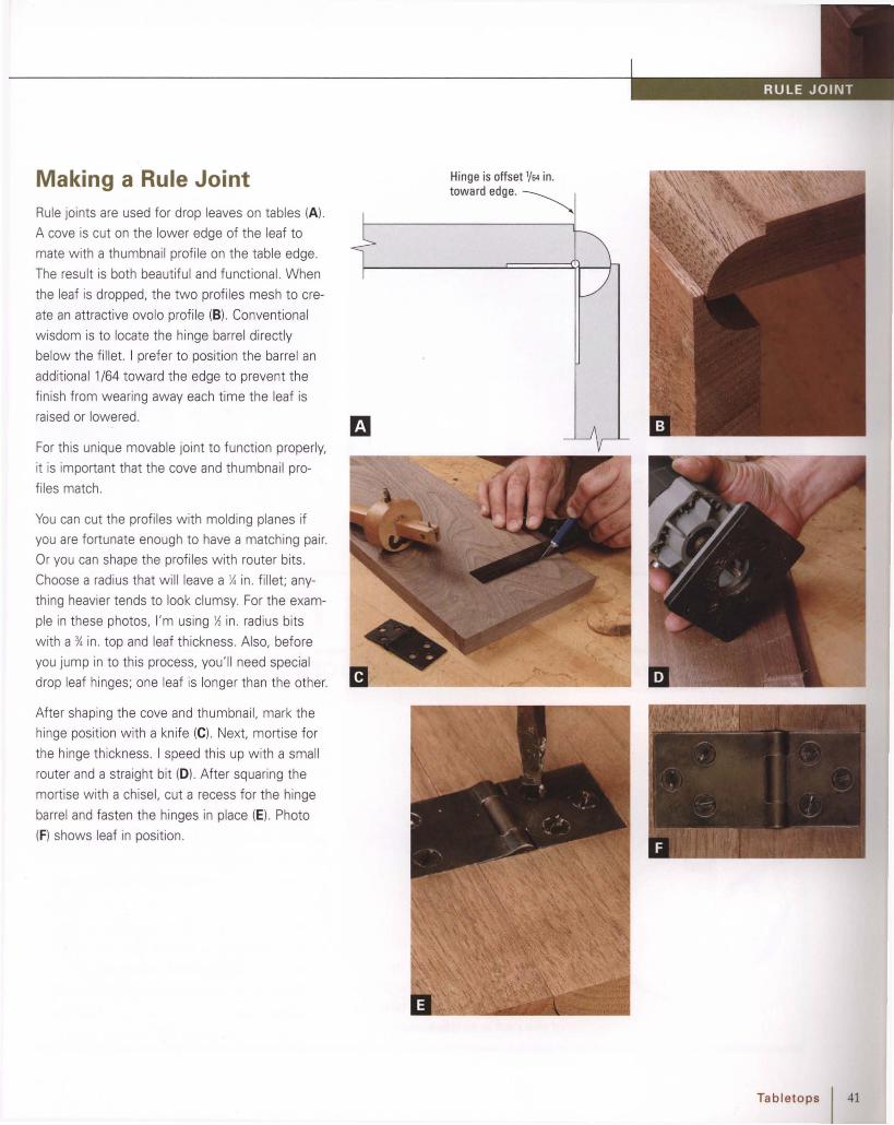
Making a Rule JointRule joints are used for drop leaves on tables (Al .
A cove is cut on the lower edge of the leaf to
mate w ith a thumbnail profi le on the table edge.
The result is both beautiful and funct ional. When
the leaf is dropped, the two profiles mesh to cre
ate an attractive ovolo profile (B). Conventional
wisdom is to locate the hinge barrel directly
below the fillet. I prefer to position the barrel an
additional 1/64 toward the edge to prevent the
finish from wearing away each time the leaf is
raised or lowered.
For this unique movable joint to function properly,
it is important that the cove and thumbnail pro
files match.
You can cut the profiles w ith molding planes if
you are fortunate enough to have a matching pair.
Or you can shape the profiles w ith router bits .
Choose a radius that w ill leave a X in. fi llet; any
thing heavier tends to look clumsy. For the exam
ple in these photos, I'm using ~ in. radius bits
w ith a %in. top and leaf thickness. Also, before
you jump in to this process, you'll need special
drop leaf hinges; one leaf is longer than the other.
After shaping the cove and thumbnail, mark the
hinge position with a knife (e). Next, mortise for
the hinge thickness. I speed this up with a small
router and a straight bit (0) . Afte r squaring the
mortise wi th a chisel, cut a recess for the hinge
barrel and fasten the hinges in place (E). Photo
(F) shows leaf in position.
Hinge is offset 1{64 in.
toward edge.~
Tabletops I 41

Feet
»- Turning a Pad Foot(p. 44)
»- Carving a TrifidFoot (p. 45 )
»- Carving a Ball andClaw Foot (p. 47)
»- Cutting a Flat Baseon the Bandsaw(p.50)
»- Shaping Ogee Feeton the Bandsaw(p.52)
»- Ogee Bracket Feet onthe Tablesaw (p. 55)
42 Feet
The simple elegance of the
pad foot is shown in this 18th
century-style desk. The bottom
of the pad is easily turned on
a lathe.
CABRIOLE LEGS CAN TERMINATE in a
wide variety of foot styles. Probably
the most common is the pad foot,
which is quickly and easily turn ed on a
lath e. H owever, even pad feet can be far
from ordinary. For example, those produced
in Virginia are unusual looking thin disksresting on a thick platform. The spoon footis the form that is most familiar and often
reproduced.
Various forms of carved feet were also
popular dur ing the 18th century. T he slipper
foot is a slender, somewhat elongated version
of a pad foot. And the trifid, or three-toed,
foot was extremely popular in 18th -centuryPennsylvania. A study of surviving examplereveals enormous variation from thick and
clumsy to highly refined and elegant.
Today, nothing symbolizes 18th -century
furniture more than the claw-and-ball foot.
It is said to have come to America from

China, where it represented a dragon's claw
clutching a pearl. Once it migrated to the
colonies, it became a symbol of wealth and
status. A closer study of colonial furniture
reveals regional differences more than any
other style of foot. For example,
Philadelphia feet appear tense, powerful, and
perhaps the most realistic. New York feet
appear somewhat boxy while feet from
Newport have long undercut talons that
grasp a nearly perfectly spherical ball.
Bracket feetWhile it is possible to see short cabriole legs
on desks and other casework, bracket feet
were probably more common- and for good
reason. While a short, stubby cabriole leg can
appear as underdeveloped appendixes, the
bracket foot appears strong and understated.
The bracket foot takes two form s; the flat
bracket and the ogee bracket. Although nei-
The agee bracket foot is a versatile element used to
create bases for case pieces. Often used in high style
pieces, it is more elegant and sinuous than a flat base.
ther example is difficult to construct, shaping
the face of the ogee foot is somewhat more
time-consuming. Both types of bracket feet
are "capped" with a simple molding profile
such as a cove or an agee. The molding pro
vides a transition to the case and visually ties
the feet to the case as well as to each other.
REGIONAL VARIATIONS ON THE BALL AND CLAW FOOT
Ph iladelphia New York Newport
Feet I 43

Begin by bandsawing the leg. Next, locate the
cente rs and mount the leg in the lathe with the
foot at the tailstock. This avoids the possibility of
the gouge coming in contact with the drive cen
ter. Now, turn the foot round w ith a spindle
gouge (B); the roughing gouge is too large and
awkward for this cut. As you round the foot , use
care to avoid cutting the ankle, w hich would spoil
the curve of the leg.
As the work progresses, you can check for
roundness by laying the shank of the gouge on
top of the spinning foot (e) . Once the foot is
round, cut a small Vat the top of the foot to
indicate the height (0) . Next, turn the pad to
diameter w ith a parting tool and gauge it w ith
a caliper (E).
Turning a Pad Foot
The last step is to shape the foot. This step is
ident ical to rolling a bead with a spindle gouge.
For the first pass, start at the corner and round
the foot to the pad (F). Remembe r, as you turn
the foot, roll the gouge, lift the handle, and pivot
the handle (G). To avoid chatter, it's a good idea
to turn the foot in two or three passes. The final
pass should be from the V to the pad to create
a continuous curve (H).
The pad foot was the most common form of
foot used on 18th-century cabriole legs (A). It's
quite easy to turn , and the ent ire process takes
just a few minutes. You'll need to use a slow
lathe speed, because the asymmetrical
leg spins off balance.
PadFoot
Ankle
1'15/16Jdiameter
II Adjust dimensions to fit leg proportions.
44 Feet

Carving a Trifid FootThe trifid, or three-toe, foot is a simple, yet ele
gant carved foot commonly found on period fur
niture from Pennsylvania and the Delaware
Valley. Begin by bandsawing and shaping the leg.
Next, make a pattern for the bottom of the foot
to serve as a guide wh ile carving. Heavy card
board works well for the pattern ; simply incise
the outline with gouges that match the curves.
Then position the pattern on the base of the foot
and trace the outline (A).
To begin carving, secure the leg in a pipe clamp
that is mounted in a vise. For consistency, use
the same gouges for carving that you used for
incising the pattern . Carve the profile of the toes
starting at the top of the foot and working toward
the base (8). As you carve, maintain the angles
on the edge of the foot that w ere established
earlier wh en bandsawing. Invert the gouge to
carve the convex area (e. D). Afterward, smooth
and blend the areas wi th a small f ile (E).
The next step is to carve the stocking . Begin with
layout. First locate the height of the stocking with
a compass (F). Used as a divider, the compass
ensures that this measurement is consistent
from one foot to the next.
(Text continues on p. 46)
Feet I 45

To outline the concave areas that form the stock
ing, flex a straightedge into the curve and trace it
from toe to ankle (G). Now you're ready for the
next stage of carving.
Beginning at the toe, scoop out the wood be
tween the toes w ith a no. 5 gouge (H). As you
near the sharp curve at the ankle the gouge will
have a natural tendency to dig in (I). At this point,
switch to a narrow spoon gouge and carve a
little farther until the gouge begins to lift the
grain. This is a sign that the grain direction has
changed; sw itch directions and carve from the
top of the stocking to this transition point and
blend the two areas where they meet (J).
After carving, the stockings w ill be somewhat
faceted from the gouges . But sanding this area
would spoil the sharp ridges that outl ine the
stocking . Instead, use a small bent file, other
wise known as a riffler (K). This unique tool w ill
allow you to preserve the details as you smoot h
the surface .
46 I Feet

21/4in.diameter
o
~5/sin.Foot layout
__ 4 ;"~
-----------17 in. ~
T27/s in.
L L-- ---~-'-----!-_---'
I·
Carving aBall and Claw Foot
Begin by bandsawing the leg and shaping the
contours with a rasp and file . Shaping the leg first
ensures that the contours of the leg and foot
blend together.
The ball and claw foot is a classic design that has
become an icon of Colonial American furniture. It
first emerged during the mid-eighteenth century
and quickly became popular as a sign of wea lth
and status. The foot shown here (A) is modeled
after Pennsylvania examples. It featu res tense,
powerful claws gripping a slightly f lattened ball.
The next step is layout. Start by marking diagonal
lines from the corners to locate the center of the
foot. Next, draw a circle with a compass to serve
as a guide when carving the ball (8). To outl ine
the claws, draw a pair of parallel lines 0/,6 in. from
each centerline (C). Then extend each line up
ward to the ankle where the lines converge (D).
Finally, mark the apex of the ball on each of the
four faces.
With the layout complete (E), you're ready to
begin carving. The first stage involves roughing in
the contours of the ball. As the ball is shaped, the
corners of the block are further exposed to be
later formed into the claws. My favorite tool for
carving the ball is an old %-in. socket firmer chisel
about 12 in. long. The extended length of this
tool provides leverage beyond that of a standard
carving gouge for quick removal of stock . Later
on, after the contours of the ball are roughed in,
further refine the ball and remove the facets w ith
a no. 2 gouge. Start by carving from the apex of
the ball downward toward the circle on the
underside of the foot (F). Next, change directions
and carve from the apex toward the top (G)
(Text continues on p. 48J
Feet I 47

Next, turn your attention to the front. Outline the
web w ith a no. 5 gouge (l.), Then use the corner
of the chisel to remove stock at this area (Ml.
With each cut. the ball w ill further emerge and
the web will begin to form. Also. the height of
the ball will shorten as it becomes round and fully
formed (N).
Once all four surfaces of the ball begin to take
shape, it becomes easier to visualize the overall
form. Work your way around the ball once more
and refine it so that the four surfaces become
one sphere (0). Then you're ready to begin
roughing in the claws .
At the back of the foot . begin carving by outlining
the curve at the top of the ball w ith a no. 5
gouge. Aim the gouge toward the ball's center
and tap it lightly with a mallet (I). Repeat the
process several times to form an arc. Afterward,
carve the face of the ball downward toward the
arc (J). Just as on the front . carve from the apex
of the ball in every direction. and the ball w ill
begin to emerge from the block (K).
Before carving the claws, use compass as a
divider to layout the location of each knuckle (Pl.
Next, begin roughing in the claws by first remov
ing the corners (O). Then carve the excess block
away so that the claws bend at the knuckles to
follow the contours of the ball (Rl. Afte rward.
check the knuckle spacing with dividers and
make any necessary adjustments (S).
Compare the curvature of the top to that at the
bottom and keep the two alike. Add addit ional
curvature to the ball by carving across the grain
from the apex towa rd the claw (Hl.
48 Feet

, .•.~... " t\..
~~ ~~._~~.-, ----
. , :
. I
X
At the sides the claws flex inward at the sec
ond knuckle to follow the contour of the ball.
Remove stock at the back of the claw to yield
this effect (W).
Next, use a no. 7 gouge to remove the excess
stock at the web (U). This area is tough end
grain, so keep the gouge sharp for greatest con
trol. As you pare the excess stock away at the
web, the claws at the top of the ball wil l begin to
form (V). Continue to contour the web until you
reach the ankle. At this point. the web diminishes
as it blends into the curves of the ankle.
Now carve the talons. Curve the surfaces of the
talon with a no. 5 gouge and taper them to a
blunt point (X). Next, add further refinement to
the web by hollow ing the corners adjacent to
each claw w ith a no. 7 gouge (V). Finally, smooth
all of the surfaces. A no. 2 gouge will remove
facets on the surface of the ball left by the chisel
(Z). Afterward, smooth the ball with a fi le (AA).
A short bent file known as a riff ler is useful for
smooth ing the concave surface of the web (8 8).
Final smoothing is done w ith 240-grit sandpaper.
With the claws contoured to follow the ball, the
next step is to refine them (T). Using a no. 5
gouge, cut across the grain to hollow the space
between each knuckle. This gives the knuckles
a more lifelike appearance.
Feet I 49

----- ----------
Cutting a Flat Baseon the BandsawBandsawing should always begin with a pattern.
This allows you to work out proportions and cre
ate smooth, flowing curves .
Begin by carefully tracing the pattern onto the
stock (A). If there are slight imperfections in the
wood, you can often orient the pattern to locate
them in areas of offcuts.
The example for this technique is two bracket
feet joined by molding. Shape the molding before
bandsawing, while the straight reference edges
are still intact (8). The long, straight section that
spans the feet is difficult to cut with a bandsaw.
Instead, make a stop cut on the table saw. The
stop block prevents kickback (C). and a second
cut from the opposite face will reach into the
corners (0).
VARIATION You can get a straighter linebetween the bracket feet if you use thetable saw instead of the bandsaw. It'scalled a stop cut, and the way to do it
safely is with a stop block clamped to thefence or table.
50 Feet

Before bandsaw ing, mount a blade that will turn
the tightest contour without binding. Then plan
the cutting sequence to avoid trapping the blade
(E). Backing out of the turn is a sure w ay to pull
the blade off the wheels (Fl.
You can avoid tedious cleanup of the surface by
carefully sawing to the layout line (G). When the
bandsawing is complete, smooth the curves with
a spindle sander (H) and clean up the intersec
tions w ith a chisel for a crisp, defined look (I).--------~~-----
~ '-----I
------------
2nd cut(back out)
II
III
l stcut~4th cut
5th cut(back out)
8th cut
II
7th~3rd cut(back out)
Feet I 51

First mill the stock to size and cut the joinery. The
front feet are joined w ith a miter and spline.
However, the back feet are designed to fit flush
with the back of the case so they are joined with
a half-blind dovetail (B). Begin by cutting the miter
on the table saw (C). Then cut the groove for the
[ T I P ] Because it's strong and doesn'trequire milling, Y4-in. plywood makes anexcellent spline. Plywood is always lessthan the specified thickness, though, socut the spline groove to fit the plywood.
Shaping Ogee Feeton the Bandsaw
The curves of ogee bracket feet give a sculptural
effect to chests, desks, and other forms of case
work. Making them on the bandsaw is a four
step process of cutting the joints, sawing the
bracket out line, assembl ing the feet, and band
sawing the ogee contour in the face (A). For the
last step you'll need to construct a simple stand
to support the foot during sawing.
Ogee contour:Bandsaw thisareaafter thetwo halves ofthe foot areglued together.
The first stepin building an agee bracket foot is making apattern. The order in which youmake the cuts is important.
Bracketoutline:Bandsaw this area first,before assembl ingthe foot.
-------------------.--.--------... ""----------\
52 Feet

spline (D). Once the joinery is cut and fit, trace
the foot pattern onto the face of each foot (E).
[ T I P ] Before sawing intricate scrollwork,save time by drilling segments that arecircular.
When sawing the tight curves of the bracket, drill
areas that form part of a circle (F), Next, carefully
bandsaw the remainder of the bracket outl ine (G).
Now you're ready to assemble the feet. I've
found that four small clamps work well to hold
the miter joint tight whi le the glue sets . The
spline keeps the two halves from sliding out of
alignment w hen clamp pressure is applied (H),
First, you' ll need to build a support stand to hold
the foot in position during sawing (I). Keep it sim
ple: Use four boards joined w ith dadoes, glue,
(Text continues on p. 54)
a
When bandsawing curves, you can save time and ensure accuracyby using a drill to form the partsof the curve that are true circles.
Bandsaw therest of the curve.
When bandsawing an ogeecontour in a bracket foot, make sure the footis securely supported slightly above the table sothat it is parallel to the blade.
Use screws andglueto reinforcethe dadojoint.
Make the heightslightlymorethanthe foot's length.
--
Feet I 53

54 Feet
and screws. For the best results, you'll want to
build the stand as short as possible-just high
enough so that the bracket foot clears the band
saw table. This will enable you to keep the upper
saw guide positioned low for the best blade
support .
The next step is to bandsaw the ogee contour in
the face. Secure the foot to the support stand
with a small clamp while sawing (J) . After sawing
the first face, the outline for the second face is
revealed in the miter (K). Afterward, work the
surfaces with hand tools to remove the saw
marks. A rabbet plane works well for shaping the
fillets that flank the bead (L). To shape the bead,
use a carving gouge (M); smooth the ogee con
tour with a file (N). Complete the smoothing
process by using a scraper and sandpaper.

Ogee Bracket Feeton the Table SawAnother method for shaping ogee feet uses the
table saw to create the ogee contour. It involves
cutting a cove on a long strip and mitering short
lengths of the strip to create feet.
The first step is to mill a strip of lumber long
enough for all four feet. Next. the concave por
tion is created by cutting a cove with the table
saw (A). To shape the convex area, begin by
beveling the strip (8). Then use a block plane to
complete the contour (C).
When you're satisfied with the ogee profile,
miter the two halves of the foot (0) and cut a
groove for the spline (E). Next, bandsaw the
bracket outline into the face of each foot (Fl.
After gluing the two halves together (Gl. smooth
and refine each foot w ith files before scraping
and sanding (H).
Feet I 55

Bedposts
• With Shaper (p. 59)
• By Hand (p. 61)
• Carving a Lamb'sTongue (p. 62)
UN LI KE MOST CONTEMPORARY beds,
most period beds had tall posts.
Rooms were heated with a fireplace,
and much of the heat escaped through the
chimney. Tall post beds, along with their
heavy drapery, provided a room within a
room in an effort to provide extra warmth
and privacy. It was only natural for the most
wealthy gentry to order highly ornate turned
and carved bedposts. Surprisingly, even the
most ornate beds have plain, tapered posts at
the headboard where the posts were hidden
as the drapery was drawn and tied back. For
those who would not go to the expense of a
turned and carved bed, the tapered pencil
posts were a simple, if not elegant, option.
Today, the posts are easy to shape-either
with hand tools or with a router table or
shaper,
56 Bedposts
Laying out and cutting postsObviously, posts are important structural
elements, unlike purely aesthetic elements
such as moldings or carvings. So from a
design standpoint a bedpost must have suffi
cient dimension for adequate joinery. So, to
avoid creating a heavy, utilitarian look, the
remainder of the post can be reduced in size
and shaped to enhance its appearance.
A typical bedpost has slender proportions;
the post is commonly 21/ 2 in. square by
80 in. tall. A short portion of the post is left
square to accommodate the bed rail mortise
and-tenon joinery. Above the rails the taper
begins and gradually reduces in size until it
reaches the top. The top of the post is
typically 1 in. across.
You can make an octagonal taper several
ways: by hand, with a router, or with a
shaper, The first method involves using a
drawknife and plane, and is a quiet and

enjoyable method. Laying out the taper in
preparation for handwork is quick and pre
cise with a sparrnaker's jig. This special
marking gauge uses two wooden dowels,
which follow the edges of the post to guide
the pins as they scratch the outline.
See "Pencil Bedpost with hand tools"
on p. 61.
If you prefer using your router table or
shaper, you'll need to build the jig in draw
ing. T he base supports the four -sided taper
Mortising the headboard into the taper can
be tricky, but accurate layout is the key. The
rails attach to the flat part of the post and
joined with bed bolts for strength and
portability.
TYPICAL PENCIL-POST DESIGN
---1 r-1 in.
~ Tapered octagon
80 in.
V Carved lamb's tongue
I"----- Square section forbed rail joinery
I"--- Octagonal
-'-
--1 ~2 1/2 i n .
Bedposts I 57
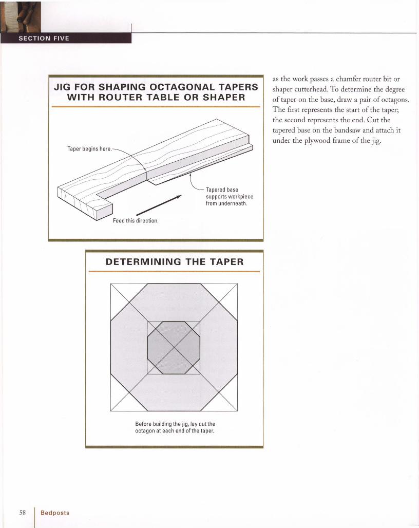
58
JIG FOR SHAPING OCTAGONAL TAPERSWITH ROUTER TABLE OR SHAPER
Taper begins here.
~ Tapered basesupports workpiecefrom underneath .
Feed this direction.
DETERMINING THE TAPER
Before building the jig, layout theoctagon at each end ofthe taper.
I Bedposts
as the work passes a chamfer router bit or
shaper cutterhead. To determine the degree
of taper on th e base, draw a pair of octagons.
The first represents the start of the taper;
the second represents the end. Cut the
tape red base on the band saw and attach it
under th e plywood frame of the jig.

Octagonal Bedpost on theRouter Table or ShaperBegin by milling the post square and draw ing an
octagon on one end. Next, mount a router bit or
shaper cutt er. If you're using a shaper, mount
the cutterhead to cut from underneath the stock
for safety (A).
The final step in the setup is to adjust the fence
and cutter height. Your drawing on the end of the
post makes it easy. Just posit ion the post adja
cent to the cutt er and lock the fence and cutter
height.
Now you're ready for the cut (8). If you're creat
ing a stop chamfer. clamp a stop block to the out
feed fence or make a mark on the fence or table
to align with a mark on the stock (e) .
Bedposts I 59

60 Bedposts
- --
3 -I
-~ \.-:---~~, -.. 1$ ~ -- ".
{
Pencil Bedpost on theRouter Table or ShaperBefore shaping a tapered octagon, always begin
by drawing two full-size octagons. The first rep
resents the start of the taper; the second draw
ing represents the end.
Next, layout a four-sided taper on the stock (A)
and cut the four tapers using your favorite
method (8). Now you're ready to chamfer the
corners to create the eight-sided taper. But first
smooth away the saw marks with a handplane or
jointer (C).
To chamfer the corners, first build a jig to support
the stock during the cut. Next, mount a chamfer
cutterhead or bit on your shaper or router table
(0). Adjust the bit height for the full depth of cut
according to the drawing you made earlier (E).
The jig wi ll raise and support the small end of the
stock to create the necessary amount of chamfer
at each end (F).
Posit ion the wo rk in the jig with the trailing end
of the stock resting firmly against the stop. Now
feed the workpiece and jig past the cutterhead to
cut the tapered chamfe r (G). When you reach the
end of the taper, stop and make a mark on the
table or fence (H). This gives you a reference
point when cutting the three remaining chamfers.

Dowel guides
Dowel guide
Distance between
...... ................~ dowel 9 U~.des
..... Width of finished face ofoctagon at top of post
...... ....... .......
. .
To remove the excess stock, use a draw knife,
which will enable you to take large, contro lled
cuts (0) . As for any hand tool , sharpness is a key
to control. Once you've gotten close to the layout
lines, finish the surface w ith a plane, taking the
stock to the layout line (E).
Finally, carve a bevel at the termination of the cut
to create a stop (F).
If you're unfamiliar with using hand tools, creat
ing octagonal tapered bedposts by hand is a great
way to get started.
Begin by shaping a four-sided taper using any of
the previous methods . Next, lay out the cham
fered corners. This step may seem complicated,
but it's easy wh en you take a few minutes to
build a spar-maker's gauge (8). If you keep the
gauge's dowels against the stock, the pins will
mark a perfect taper (e) .
You don't need a router or shaper to create ele
gant octagonal tapers ; as with any woodworking
process, there 's a way to achieve the same
results with hand tools (A).
Pencil Bedpostwith Hand Tools
Bedposts I 61

Carving a Lamb's Tongue
To create visual unity, you'll probably prefer to
finish the detail by hand. One option is simply to
make both surfaces either curved or beveled.
Either choice is att ractive, and each creates a
more contemporary look.
When creating an octagonal taper wit h a router
or shaper, the cutter w ill leave the end asym
metrical (A). Because the tool cuts in a spin
ning motion, one face will be an are, the other
a bevel.
Another more traditional approach is to carve an
ogee at the end of the taper (8). This detail is,
obviously, a bit more time consuming. But the
unique effect is worth the effort because of the
distinction it adds to the piece.
Start shaping the lamb's tongue by removing the
excess stock with a chisel, bevel down, and then
bevel up (E). The convex segment of the lamb's
tongue intersects the post at a crisp inside corner
(Fl . If the grain is running in a reverse direction,
cut across the grain to prevent tearout (G). To
finish the detail, smooth it with a file (H) .
To carve a lamb's tongue on a post, begin by
drawing the design along the edge of thin ply
wood to make a pattern (e) . After bandsawing
and smoothing the curves with a file, trace the
pattern onto the post (D) .
A chamfer bitorcutter will notcre ate asymmetrical stop. Oneface will be beveled.The adjacentfacewill be curved.
Beforecarving, makeapattern fortracingthelamb'stongue onto the post.
62 Bedposts

Chairs
~ Resawing a Splat(p. 66)
~ ScrollsawingInterior of a Splat(p. 68)
~ Beveling SplatEdges (p. 69)
~ Making an Armand Post (p. 70)
~ Carving a Volute(p. 74)
~ Bandsawing ChairLegs (p. 75)
~ Flush TrimmingChair Legs (p. 76)
~ Chamfering ChairLegs (p. 77)
~ Round ing a SimpleCurved Leg (p. 78)
~ Making a ChairShoe (p. 79)
~ Chair Side RailTenons (p. 80)
~ Carving a Shell(p. 81)
CHA I RS A RE AMON G TH E most ele
gant forms of 18th-century furni
ture. But the unusual angles andflowing compound curves th at give chairs
their grace and beauty also make them a
challenge to build. Fortunately, many periodchairs share a commo n framework and con
struction methods. So once you've constructed
one type of chair, you will find that other
types are variations along the same theme.Although there are regional differences, suchas the through rear tenon on manyPennsylvania chairs, most differences are in
the propo rtions and the aesthetic designdetails. Let 's take a look at some commo nly
shared chair details.
BacksEarly chairs of the period had straight backs.
But once the Queen Anne style gained popularity, the straight lines ofWilliam-and
Mary gave way to the reverse curve. Later, as
furniture evolved into the Chippendale Era,
the bow back became favored. Finally,
design came full circle, as it often does, and
the straight back was once again popular.
SplatsSplats were the classic, solid vase-shaped
form during much of the first half of the
century. As furniture became more elaborate,
the splats were pierced and often carved.
One important detail is the bevel along the
edges of the splat. This small detail gives the
Chairs I 63

64
COMMONLY SHAREDCHAIR DETAILS
Carved ear
Backleg~
IChairs
Armpost
splat lightness and allows the viewer's eye to
see the true profile at the front of the splat
without distraction from the back edge.
Later on, splats gave way to pierced and
carved ladder rungs and eventually to elabo
rately inlaid Federal shields.
JoineryMortise-and-tenon joinery was the predom
inant method for constructing the frame
work of a chair. The joints were often
strengthened with wooden pins and, in the
case of many Pennsylvania chairs, the side
seat rail tenon goes through the back leg
post.
Of all the joints in the chair, the tenon at
the back of the side seat rail is most compli
cated to layout and cut . Because of the com
pound angle involved, it is best to derive the
layout from fully developed drawings of the
seat and back.
ArmchairsPeriod armchairs are not simply sidechairs
with arms added. Instead, they are wider and
deeper than a matching sidechair. As you
might expect, the frame members of an arm
chair, such as the legs, splat and crest rail, are
larger, too, in order to keep with the heavier
proportions in the seat.
When developing an armchair, designing
an attractive arm and support can be a chal
lenge . Although separate pieces, the com
pleted arm and post should appear as one
flowing, sculptural unit. The post is first
joined to the arm with a tusk tenon, which
doubles the glue surface area. Then the two
are bandsawed, shaped, sculpted, and finally
carved. The result of this tremendous
amount of work is worth the effort; the arms

>- NEST PARTS TO SAVE LUMBER
Let's face it, sawing curves is wasteful. But
one way to avoid needlessly wasting excessive
stock is to nest parts together. When I select
stock for chair legs, I look for pieces wide
enough for at least two or three legs. This has
the added advantage of getting a consistent
grain and color match for the parts.
You can reduce waste substantially bynesting parts together. Here, I've used a plywoodpatternto draw two nested sets of Chippendale chair rear legson onewide board.
Waste area
provide a sculptural addition to the chair,
not to ment ion the degree of support andcomfort that they add.
LegsThe front legs of 18th-century chairs were
often highly decorated, using the cabriole leg
and the ball and claw foot in my period
styles. The rear legs were quite simple, buthave a fluid shape in keeping with the overall
design of the chair. W hen making a set ofchairs, it makes sense to maximize the avail
able stock by nesting parts.
See "Cabriole Leg "and "Ball and Claw
Foot" on pp. 34 and 47 for information.
The arm and post are cut and shaped as separateunits, then sculpted and carved to create a unifiedappearance.
Chairs I 65

)- ----
Resawing a SplatResawing is the process of ripping a board
through its thickness. By resawing a shallow
curve, you can create wide, curved panels such
as chair backs.
Begin by selecting stock thick enough for the
curve. To create a curve that is free of dead
spots, it's best if the stock is thick enough to
bury the blade throughout the entire cut.
I prefer a wide (1 in. or more) blade with a
coarse, variable pitch (A). If your saw won't ten
sion a w ide blade, select a %in. variable pitch
blade and tension it as much as possible. Also
check the table for squareness to the blade
before you begin.
66 Chairs
Bandsaw the convex face first by carefully saw
ing freehand to the layout line (8). Then remove
the saw marks w ith a spokeshave.
By skew ing the spokeshave, you can avoid
tearout in most instances (C). Otherwise, switch
to a scraper (0) .

To resaw the second face, use a point fence (E).
This simple device is a great aid for keeping the
two cuts parallel and the wo rk of uniform thick
ness. Clamp the fence so that the point is posi
t ioned parallel to the teeth of the blade. Before
making the cut, scribe a layout line parallel to the
first fence. As you saw, follow the line precisely,
making sure the wo rk is in contact w ith the
fence (F).
When smoothing the concave face, work w ith
the grain, from the ends to the middle, to reduce
tearout (G).
Attach the pointto resaw curves;remove it to resawveneer.
The fence face ishigh enough tosupportwide boards.
All partsare made of high-qualityplywood or MOE
Chairs I 67

Scrollsawing Interiorof a SplatThe scrollsaw is the tool of choice for interior
cuts . (A jigsaw can also be used, but it won 't be
as accurate and wi ll require more cleanup with a
fi le and sandpaper.) The blade of a scrollsaw can
be unclamped at one end and threaded through
a hole in the workpiece. Because the blade is
clamped securely at each end, the cut is precise
with minima l flex.
As an example of this process, I'm using a
curved chair back. When tracing the pattern, it's
necessary to flex it so it conforms to the curve of
the work. You can hold it in position with clamps
whi le tracing the outline (A).
Next, drill a small hole at each interior cutout for
threading the blade (8). When sawing, take your
time and follow the layout lines closely; this
greatly reduces the amount of tedious cleanup
later (C).
To create the illusion of thinness and delicacy,
scrollwork is sometimes beveled on the edges.
It's time-consuming work, but the refined appear
ance is worth the effort.
See "Beveling Splat Edges" at p. 69.
68 I Cha irs
VARIATION You can also use a coping
saw or fretsaw to cut interior curves byloosening the blade and freeing it so
that you can enter the work through thedrill hole.

Beveling Splat EdgesBeveling the edges of curves is a centuries-old
technique for making the stock appear thinner
than it actually is. This detail creates an illusion
of lightness without sacrificing strength.The
difficulty is that the work of beveling all those
tight, interconnected curves is extremely
tedious.
To help speed the process, first bevel the edges
with a modified router bit. Beginning with an
inexpensive high-speed steel router bit (A), grind
away most of the steel to create a chamfer bit
w ith a 15-degree angle (8).
Next. mount the bit in a laminate tr immer, wh ich
is really a small router (C). The small base will
easily follow the curved surface of the splat, and
the small-diameter pilot on the bit reaches into
the corners (0 ). Before beginning the cut, adjust
the depth so that the pilot of the bit just grazes
the edges of the surface.
After routing, you w ill still need to carve the cor
ners (E) and complete the bevel. But much of the
tedious handwork has been eliminated.
/
Chairs I 69

Making an Arm and PostThe following techniques are useful for creating
furn iture (especially chairs) that is composed of
flowing , sculptural curves. As an example, I'm
going to use an arm and post from a chair.
As w ith any bandsawn component, it's important
to begin by sketching the design and creating
patterns (A). This provides an object ive starting
point fo r logical progression. After milling the
stock to size, trace the arm pattern (B) and band
saw the outline of the arm (e) . It makes sense to
saw the contou r before cutt ing the mortise for
the post ; the convex curve of the arm wor ks as a
reference point for the joint.
After bandsaw ing the arm, lay out (0) and cut the
mortise (E). Next, lay out the curves of the arms
and the tenons (F). Then cut the tenons on the
post w hile the stock is still square (G). because
square surfaces are best wh en cutt ing joints on
the table saw (H).
70 I Chairs

Next bandsaw the post-first the front (I) and
then the side. Save the offcuts from the first
series of cuts and tape them back into position
with double-sided tape for sawing the adjacent
surface (J) .
Next bandsaw the curves on the top and bottom
of the arm. Because the arm is asymmetrical, it's
important to plan the cutting sequence careful ly
to avoid a miscut and spoiling the arm. More
specifically, as the arm curves, the profile is
simultaneously stretched and compressed .
After tracing the patterns (K). saw a relief cut
at the base of the knuckle. When start ing the
cut, it's necessary to raise the back end of the
arm so that the layout line is parallel to the blade
(Ll. Next. cut from the post joint to the cut you
(Text continues on p. 72)
Chairs I 71
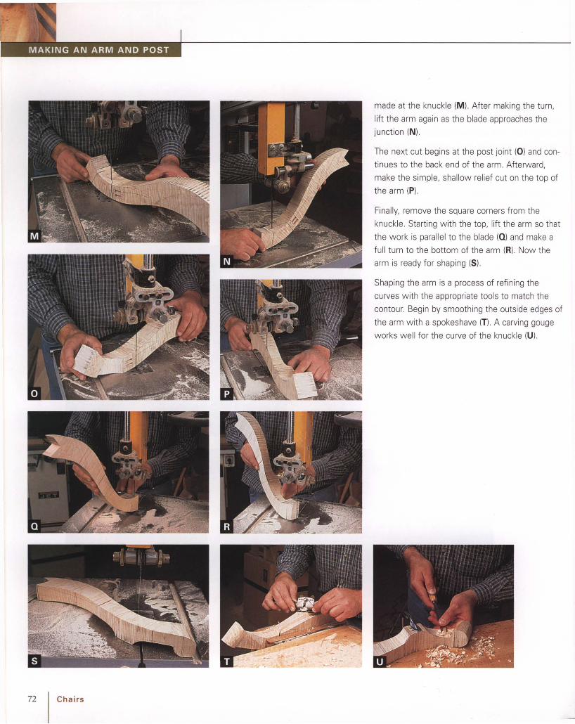
72 Chairs
made at the knuckle (M). After making the turn,
lift the arm again as the blade approaches the
junction (N).
The next cut begins at the post joint (0) and con
tinues to the back end of the arm. Afterward,
make the simple , shallow relief cut on the top of
the arm (P).
Finally, remove the square corners from the
knuckle. Starting with the top, lift the arm so that
the work is parallel to the blade (a) and make a
full turn to the bottom of the arm (R). Now the
arm is ready for shaping (5).
Shaping the arm is a process of refining the
curves with the appropriate tools to match the
contour. Begin by smoothing the outside edges of
the arm with a spokeshave (T). A carving gouge
works well for the curve of the knuckle (U).
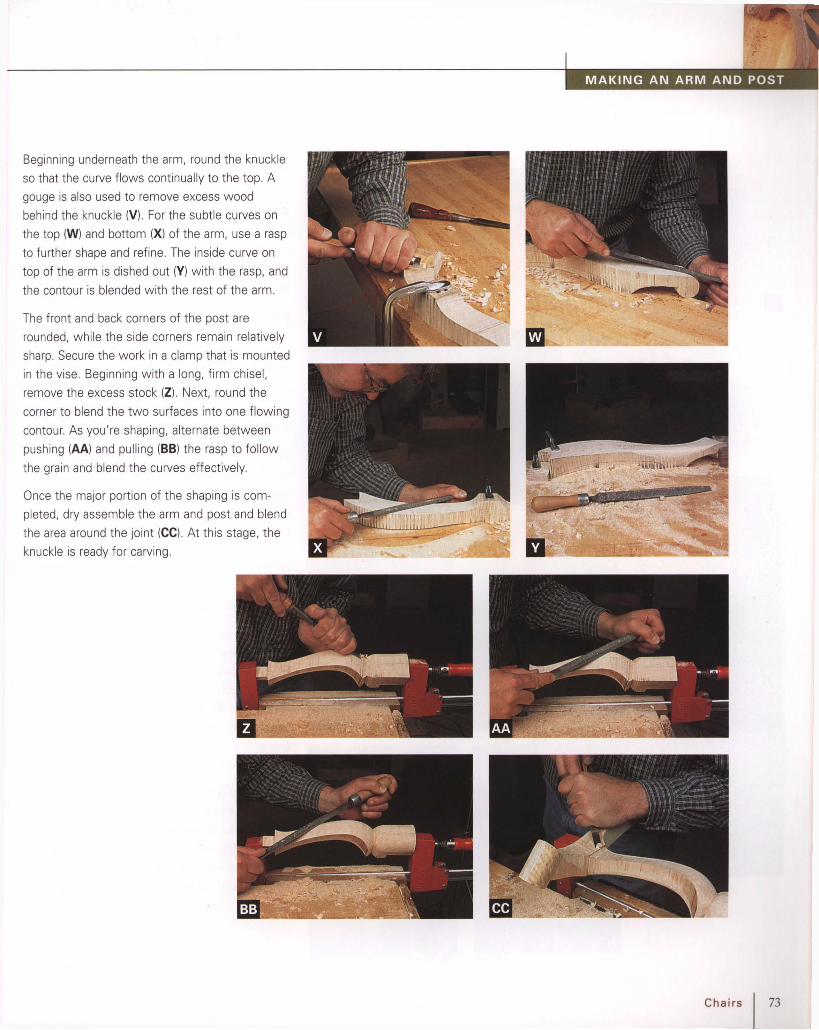
Beginning underneath the arm, round the knuckle
so that the curve flows continually to the top. A
gouge is also used to remove excess wood
behind the knuckle (V), For the subtle curves on
the top (W) and bottom (Xl of the arm, use a rasp
to further shape and refine. The inside curve on
top of the arm is dished out (V) w ith the rasp, and
the contour is blended w ith the rest of the arm.
The front and back corners of the post are
rounded, while the side corners remain relatively
sharp. Secure the work in a clamp that is mounted
in the vise. Beginning w ith a long, firm chisel,
remove the excess stock (Z). Next, round the
corner to blend the two surfaces into one flowing
contour. As you're shaping, alternate between
pushing (AA) and pulling (88) the rasp to follow
the grain and blend the curves effectively.
Once the major portion of the shaping is com
pleted, dry assemble the arm and post and blend
the area around the joint (CCl. At this stage, the
knuckle is ready for carving.
Chairs I 73
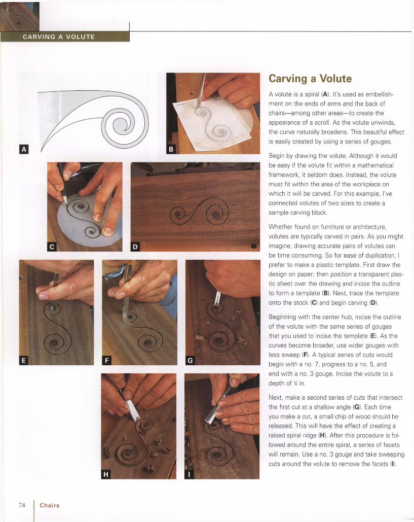
Next, make a second series of cuts that intersect
the first cut at a shallow angle (G). Each time
you make a cut, a small chip of wood should be
released. This w ill have the effect of creating a
raised spiral ridge (H). After this procedure is fol
lowed around the entire spiral, a series of facets
w ill remain. Use a no. 3 gouge and take sweep ing
cuts around the volute to remove the facets (I).
Whether found on furniture or architecture,
volutes are typically carved in pairs. As you might
imagine, drawing accurate pairs of volutes can
be time consuming . So for ease of duplication, I
prefer to make a plastic template . First draw the
design on paper; then position a transparent plas
tic sheet over the drawing and incise the outline
to form a template (8). Next, trace the template
onto the stock (e) and begin carving (0 ).
A volute is a spiral (A). It's used as embellish
ment on the ends of arms and the back of
chairs-among other areas-to create the
appearance of a scroll. As the volute unw inds,
the curve naturally broadens. This beautiful effect
is easily created by using a series of gouges.
Begin by drawing the volute . Although it would
be easy if the volute fit w ithin a mathematical
framework, it seldom does. Instead, the volute
must fit within the area of the workp iece on
wh ich it w ill be carved. For this example, I've
connected volutes of two sizes to create a
sample carving block.
Beginning wi th the center hub, incise the outline
of the volute with the same series of gouges
that you used to incise the template (E). As the
curves become broader, use wider gouges with
less sweep (F). A typical series of cuts would
begin w ith a no. 7, progress to a no. 5, and
end w ith a no. 3 gouge. Incise the volute to a
depth of ~ in.
Carving a Volute
74 Chairs

II -
Bandsawing Chair LegsAlthough you can bandsaw a broad curve with a
narrow blade, it requires more concentration and
effort because a narrow blade has a natural ten
dency to wander in the cut. I prefer to use a
wide blade (A). because it naturally follows the
broad curves of components such as chair rock
ers. After mounting the blade, trace the pattern
onto the stock (8) . Then carefully follow the lay
out line (C).
Use a compass plane to smooth the surface after
sawing (0) . The flexible sole wil l adapt to both
convex and concave surfaces (E). Clamp the
matching pairs of stock together to check for
square (F). If you don't have a compass plane, a
spokeshave can be used to clean up the surface .
Chairs I 75

f-----------
Toggle clamps holdstock to template.
To the shank of the bit, add a bearing that wi ll fol
low the template (8). After bandsawing the leg
heavy of the layout line, position the leg in the
temp late for the first cut (e). The order that you
complete the cuts is important . because the tem
plate is designed to remove equal amounts for
each of the two cuts. Cutt ing out of order means
that the first cut w ill be too heavy. In addition, if
you cut out of sequence there will not be suffi
cient stock for removal during the second cut.
Start the cut with the bearing in contact w ith the
extended portion of the temp late base (0) . This
will give you a smooth entry into the cut. Feed
the stock at a steady rate and listen to the
machine to determine if you' re feeding the stock
too quickly (E). Afterward. reposition the leg and
make the second cut (F).
Flush Trimming Chair Legson the Router TableBandsaws don't create a finished surface; so
after sawing curves, the saw marks must be
removed . Without a doubt. the router is the
most versatile tool for template shaping. It cuts
curves, flush cuts, creates molded profiles, and
shapes into tight corners. A template -guided
straight bit w ill do the job quickly and efficiently.
For th is example. I'm using the rear leg of a
chair. A pair of toggle clamps secures the leg in
the template. wh ich is equipped with two edges:
one for the leg's face and the other for the leg's
back (A).Template extends )beyond workpiece,so startingpinis not necessary.
Feed direction
Block resiststhrust ofcutterhead, preventingstock from moving
• I.at~eraIlY.
3/4-in. plywood
Spindlerotation
Stopblocksare glued andscrewed to base of template.
76 Chairs

Chamfering Chair LegsWhen shaping a chamfer on a curved surface,
the bearing on the router bit registers against the
stock to limit the cutting depth . Any roughness
or void in the surface will be re-created in the
chamfer as the bearing rolls over the surface .
Begin by smoothing the curved surface. The
bandsaw marks can be cut away with a spoke
shave or compass plane. Another option is to
flush trim the surface with a template and flush
trimming bit.
The next step is to mount a chamfer bit in the
router table and adjust the height for a light cut ,
no more than Yo in. You'll also need a fulcrum to
pivot the wor k into the spinning bit. Otherwise
the stock could kick back violently. The fulcrum
can be a pin or block; for the greatest mechanical
advantage, it should be located as close as possi
ble to the bit.
To make the cut, position the workpiece against
the fulcrum and pivot it into the spinning bit (A).
Once contact is made with the bearing, begin
feeding the workp iece (8).
When making a stopped cut on a curved surface,
it will be necessary to begin two of the cuts in
the middle. Position the workpiece against the
fulcrum and aim the start of the cut for the outer
cutt ing circle of the bit (C). If you come up short
of the line, don't back up! Instead, pull the work
away and try again.
Chairs I 77

Chamfer thefour cornerswith a router bit.
Rounding a SimpleCurved Leg
This method of rounding is useful when the leg is
rectangular in section rather than square. When
rounded, a rectangular leg becomes ellipt ical. By
shaping it, you effectively lighten the look and
add refinement wi thout a loss of strength (A).
Chamfer the eightcorners with a rasp.
Round and blendsurfaceswith a file.
To make the process more efficient, f irst remove
the excess stock with a chamfer router bit (B).
Next, mark a centerline as a guide wh ile shaping
(e) . Then clamp the leg in a vise and shape the
leg with a rasp in the direction of the grain (D).
When the grain direct ion changes, reverse the
rasp and pull it toward you (E). Work gradually to
the centerl ine to create an ellipt ical contour (F).
When you're satisf ied w ith the overall shape,
smooth the leg wi th a file (Gl, fo llowed by a card
scraper (H).
78 Chairs

Making a Chair Shoe
When speaking of chairs, the shoe is a pedestal
that is glued to the top edge of the back seat rail
to provide a term inus for the splat. The top edge
of the shoe is mortised to accept the backsplat
tenons.
First, mill the stock to size. I always dimension
the stock w ide enough for two shoes; the wider
size adds safety and stability as I cut the cove. If
I'm making a single chair, I'll just set the extra
shoe aside for a future chair.
Next, mark the w idth and depth of the cove on
each end of the stock as an aid for setting the
fence angle on the tablesaw. After cutt ing the
cove (A). rip the shoe to the final w idth (8) Next,
shape the thumbnail profile on the top edge of
the shoe on the router table (e) . Featherboards
hold the stock in position and prevent it from tip
ping and spoiling the profi le.
The next step is to bandsaw the long, curved pro
file on each end of the shoe. Because of the
cove on the face, it is easiest to layout and saw
the profile from the back. To stabilize the wo rk
piece whi le bandsawi ng, I clamp it in the jaws of
a wooden handscrew (D).
Finally, layout the mort ises for the splat (E) and
cut them w ith your favorite method (F), (G).
Chairs I 79

80 I Chairs
Chair Side Rail TenonsOf all the tenons on a period chair, and there are
a number of them , the side rail tenons are most
complicated. This is because the angle of the
back legs combines with the tapered seat frame
to create a compound angle at the intersection of
these members. To correctly layout the tenons, it
is best to first create full-sized drawings of the
chair back and seat.
First, layout the tenon shoulders, faces, and ends
with a knife (Al. (8). Next, saw the faces of the
tenons and carefully follow the layout lines. For
greatest accuracy, it is best to saw from each
corner (C) and allow the two cuts to meet in the
middle. Next, saw the tenon shoulder and then
pare to the line w ith a chisel (0). The chisel edge
w ill easily follow the knife line you created earlier
(E). (F) shows the completed pair of tenons.

Carving a ShellThe first step is to draw and proportion the shell
that you would like to carve. All carvings, includ
ing shells, can be varied in size and proportion
to fit wi th the design of the furnitu re to w hich
they're applied. The shell shown here (A) is a
five-lobe example that I designed for a
Pennsylvania armchair (B).
When you're satisfied w ith the draw ing, make
several photocopies of it. Next, glue a copy of
the drawing to the stock for the shell (e). After
carving, this shell will be glued to the front seat
rail of the chair; it's important that the grain in the
shell runs from side to side to coincide with the
grain in the seat rail.
Contour the face ofthe lobeswith a no. 5gouge; then switchto a no. 7 gougeas the lobetapers.
Carve the veinswitha 1.5mm no. 12 gouge.
Outlinethe lobeswitha no. 7 gouge.
The next step is to select the gouges for carving.
The sweep, or curvature, of the gouge should
closely follow the outline that you sketched ear
lier. For the lobes on this shell, use a 14mm
no. 7 gouge (0) . For the area around the hinge,
use a 25mm no. 5 gouge. Although the narrow
gouge could be used for both, the wide gouge is
more efficient and easily yields smooth, uninter
rupted curves around the hinge.
The next step is to bandsaw the outline of the
shell to remove the excess stock. It's important
to saw approximate ly 1,6 in. from the line (E)
because the final outline of the shell is created
with carving tools.
Next, begin incising the perimeter of the shell
w ith gouges (F). Be aware that the grain at
the top center lobe has a tendency to split off .
To avoid this problem, position the corner of
the gouge beyond the stock when incising the
concave areas that flank the cente r lobe (G).
This will prevent the center lobe from
(Text continues on p. 82)
Chairs I 81

82 Chairs
splitting (H). The entire outline will later be in
verted to become the base of the shell, so it's
not necessary to incise beyond 'Yt6 in. deep (I) .
When incising the outline of the shell, it's impor
tant to keep the cuts vertical. To achieve this,
you'll need to angle the gouge away from the
work for the concave cuts . This will compensate
for the bevel on the edge of the tool. Also, con
centrate on keeping the cuts interconnected and
flowing uninterrupted around the shell.
When you're satisfied with the outline of the
shell (Jl. you're ready to move on. The next step
is to glue it face down to a short length of inex
pensive stock . Afterward, the clamps are posi
tioned on the scrap stock to give you full access
to the shell for carving. Don't use a lot of glue;
the shell must be pried up after carving. Besides,
a small amount of glue is all that's necessary to
hold it firm ly (Kl. Clamp the shell to the board and
allow the glue to thoroughly dry (Ll.
The next stage of the process is to contour the
face of the shell. But first mark the high point of
the contour. The point is centered left to right and
slight ly below center from top to bottom (M) .
Now select a 25mm no. 2 gouge for shaping the
contour. The goal of this process is to produce
sweeping curves from left to right and top to bot
tom (N). After paring the face of the shell, the
only original surface remaining will be the high
point that you marked earlier. Watch the grain
direction and cut with the grain or across; you'll
want to produce clean shavings, not splinters.
Carve the surface down to the 'Yt6-in. perimeter
that you incised in the first step .
After carving the contour, you can remove any
remaining facets with a smooth fi le (0) . Avoid
using sandpaper though-the abrasive grit will

sett le in the pores of the wood and quickly dull
your tools later in the process.
The next step is to draw the lobes as a guide for
carving. Using your original drawing as a guide,
locate the points of the lobes w ith dividers (Pl.
Then divide the base of the shell into equal
spaces (0). Next, connect the points by sketch
ing smooth , flowing curves (Rl. To achieve visual
balance in the carving, spacing is important.
Examine the curves closely and, if necessary,
redraw any that need improvement.
Now you're ready for the next stage of carving.
The first step in this stage is to incise the hinge
area. Hold a 25mm no. 5 gouge nearly vertical to
create a steep wall (5) and carve this area gradu
ally until you reach the layout line (T). Finish the
inside corner wi th a 6mm no. 7 gouge. Take long,
swee ping cuts to blend the wall wi th the hinge
area (U).
The next step is to outline the curves on the face
of the shell with a V gouge. For greatest contro l,
take several light cuts and progressive ly deepen
the V. Also, as you carve the v 's, watch the spac
ing and flow of the curves; if necessary, make
corrections as you deepen the cuts (V).
Next, carve the convex lobes. Start by contouring
the ends of the lobes with a 12mm no. 5 gouge
(W). As the lobe tapers back, the curvature
becomes tighter, so you'll need to sw itch to a
10mm no. 7 gouge; then a 6mm no. 7 gouge.
Gradually, as the lobe reaches the apex of the
shell, sw itch to a 4mm no. 7 gouge. Finally, the
curve on the face of the lobe diminishes.
(Text continues on p. 84)
Chairs I 83

84 I Chairs
Next, carve the concave rays between the lobes
(X). Beginning with a 10mm no. 7 gouge, work
back gradually; then switch to a 6mm no. 7 and,
finally, a 4mm no. 7 gouge. As you carve the rays
and lobes, use the gouges to blend the curves
(V). During the entire process, stop periodically
and hone the gouges; sharpness is the key to
accuracy and control.
The final step is to carve the veins into the
surface of the hinge. These tiny U-shaped
grooves break up the flat surface to add more
interesting detail.
Starting at the outer edge, sketch each vein with
a pencil (Z). Keep the spacing uniform and follow
the curve at the edge of the hinge. Next, use a
1.5mm no. 11 gouge to carve the veins (AA).
The completed carving should be crisp, flowing,
and full of visual details (BB). You can smooth
the carving lightly with 240-grit sandpaper to
blend the facets . But be careful not to spoil the
sharp details .

Casework
Arched Molding
~ Cutting Half-blindDovetails (p. 94)
~ Turning a FlameFinial (p. 109)
~ Carving a FlameFinial (p. 113)
~ Finial Pedestal(p. 117)
~ Seat Board on theRouter Table (p. 96)
~ Template ShapinigReturns (p. 97)
~ Divider (p. 98)
~ Shaping InsideCorners of a Divider(p.99)
~ Arched Light SashDoor (p. 118)
~ Tombstone Door(p. 120)
~ Small TombstoneDoor (p. 123)
~ Shaping a LippedDoor Edge (p. 125)
~ Hanging LippedDoors (p. 126)
~ Gooseneck Moldingon the Shaper(p.100)
~ Gooseneck Moldingon the Router Tablewith Pin Jig (p. 103)
~ Mitering aGooseneck Molding(p.105)
.s-:~~
Flutes and Reeds
~ Large FlutedPilaster (p. 127)
~ Carved ReverseStop Flutes (p. 128)
~ Fluted QuarterColumns (p. 129)
~ Reeded Turning(p.132)
~ Arched MoldingEdge on the RouterTable (p. 106)
~ Base and CapitalMolding(p.134)
~ Shaping the Edge ofBase and CapitalMolding (p. 135)
~ Turning a Rosette(p.107)
~ Carving a Rosette(p.108)
~ Turning a FlameFinial (p. 109)
~ Carving a FlameFinial (p. 113)
~ Candle-Slide Fronts(p.136)
Casework I 85

-------
86
This tea caddy has the Golden
Rectangle proportions of 1:1.618. The
height equals 4 in. The length to the
outside of the box equals 6~ in.
(4 in. x 1.618 = 6.472 in., which
rounds up to 6~ in.)
The small tombstone door of the gallery in this desk fits
into the Golden Rectangle.
I Casework
PERIO D CASEWORK CAN SEEM exceed
ingly complex. Yet, if you strip away
the feet, moldings, curves, and other
details from period casework, what remains is
a dovetailed box. The drawers are just a series
of boxes fit within the larger box. The key to
building large, complex period casework is to
divide the process into small, manageable
steps. Once the box is constructed, the period
details, such as tombstone doors, ogee feet,
and complex moldings, are added to make
the piece visually stimulating.
Proportioning caseworkMter years of studying period furniture, I
am convinced that the craftsmen of the time
used mathematical systems for proportion
ing. Two of the most common of such sys
tems were ratios of whole numbers and the
Golden Rectangle. With a ratio of 1:1.618,
the basic geometric shape has been revered
for centuries by architects, designers, and
craftsmen as having perfect proportions.
Some examples include the Parthenon and
the credit cards you carry in your wallet.
Amazingly, it is the only rectangle of which
you can derive a square and the remaining
space forms another Golden Rectangle.
The diminutive tea caddy is my reproduc
tion of one that a client found years ago at
an antique shop . A few quick measurements
reveal that the front of the box fits within a
Golden Rectangle, yet when viewed from
the top, the box has a ratio of 2:1. During
the 18th century even something this small
and inexpensive was carefully proportioned.
Once a cabinet has been proportioned,
the details within the case must be propor
tioned if the completed case is to be visually
successful. For example, as the focal point of

ANATOMY OF A PENNSYLVANIA SECRETARY
Face frameFace frame
Casehalf-binddovetails
Lid
Crown mold ing
Lid support
.....--- Tombstone/' doors
Drawerdividers
C Tenons
Breadboardends
Writingsurface
Drawers
Top of lower case
Bottom oflower case
Shelves
Dividers
Faceframe-\------'---<-1
~~;tII:::::::::::::::::::::::::::=f=::::::::::::::::::::::::.f:.~~ Top of uppercase
- - _.--
Backfoot
molding
(
Uppercase side
Lower casesides
Backboards
Casework I 87

the gallery in the small tombstone door fits
perfectly within a Golden Rectangle.
Drawers look best if they graduate, that is
they deepen as they progress. One sure
method is to use the system of arithmetic
progression. It works like this: A constant
value X, is added each time to size the next
drawer in the series. Using the drawer
divider as X works well. For example, assum
ing a value 0£7/8in. for X, the first drawer
measures 3'/2in., the next three measure4% in. , 5'/4in., and 6'/8in.
Finally, use proportioning systems as a
guide and feel free to change dimensions as
the design progresses. Your eye should
always be the final judge.
PedimentsAlthough flat top case pieces are quite
attractive, gooseneck pediments seem to
command attention when you enter the
room. As the graceful "S" curves rise toward
the center of the pediment board, they often
terminate in a turned and carved rosette.
Crowning the pediment is a turned and
carved finial. O ften the finial is flanked by
matching finials which are positioned on the
lower corners of the pedim ent near the miter
of the gooseneck moldin g.
When making a gooseneck pediment, it is
always a good idea to start with a drawing to
work out the dimensions and proportions.
Once you have drawn the "S" curve, you can
duplic ate the parallel curve with the simple
jig in the sidebar on p. 90.
The details of rosettes and finials should
also be first worked out in a full-scale draw
ing, then a three-dimensional prototype. A
prototype brings this type of work to life
and is a great aid in determining the rela-
Neckmoldingadds detail.
Fluted pilasteremphasizesvertical lines.
Thumbnail edgerames panels.
~waistmoldingvisuallyseparatesupperandlower cases.
I-r- Crown~ molding
---L....... Base cap--r provides
transitionbetweencabinetand foot.
MOLDINGS ON A CORNER CABINET
~ ~~~
I~~I
edge Vs
I-v v 1"--IT
!== I ~~ I,1== I
!=:::= I :
~ R'~-~I~~I '
/~I--
fV
IT
;::=:: I~ ~ I;::=:: I
I
Ovoloframeglasslight.
88 Casework

tionship of the various elements to eachother, as well as to the rest of the pediment . PROPORTIONING DRAWERS
£ :'1'l'31{2-L
T3{S
-.L
T1{4
-lT
I{S
~
o --=- 0
o~ 0
@
0 0 II II II 0
~\~r:r=:\ r:r=:\ [:r\ V\
0
<>0 0
0 1= ;::: 0 0
~ I U ~> IIII ~ ~ 4
~ ~> 5
~ ~> 6
~ "\J
Casework joineryBecause of the myriad ofjoints used in peri
od casework, reproducing period casework
requires a mastery of joinery. The predomi
nate joint was the half-blind dovetail. Unlikethe through dovetail, the half-blind variation
is exposed on only one face. This methodnot only prevents the joint from distracting
from other more prominent details (a seem
ingly prevalent thought of the period), it is
also prohibits seasonal movement from
pushing on molding that may cover the area
around the joint.Because jigs cannot dupl icate the myriad
of variations of period dovetails, it is best to
develop the skill to cutting them by hand.
Although the skills may seem difficult to
master, cutting dovetails is really just sawing
and chiseling to a layout line. The key isaccurate layout . It should be done with a
knife and a marking gauge. These tools leavea crisp incision that is a great aid to sawing
The graceful curve of the gooseneck mold
ing on this period clock calls attention to
the flame finial in the center. Rosettes
enhance the termination points.
Arithmetic progress yieldspleasing proportions in a series of drawers.
Casework I 89

and chiseling. A pencil should be avoided .
Pencil lines have thickness and create an
indefinite layout line that is imprecise.
The ongoing argument of cutting pins or
tails first is moot. The goal is always to pro
duce a precise, tight-fitting dovetail joint
that is authentic to the period. As with
much of woodworking, there are several
paths to reaching the goal.
The drawer dividers in large casework are
typically joined to the case with a sliding
dovetail. As you might expect, there are
regional differences. For example, on some
New England pieces, the dovetail is through
so that the end of the divider can be seen on
the sides of the case.
The desk gallery with its intricate
arrangement of drawers and pigeonholes
appears difficult to construct but is actually
After bandsawing thenegative pattern of thecurve, trans-fer it to asecond sheetof plywood.
An accuratepatternresults fromcutting tothe parallelline.
Use a diskequal inradius to thewidth of themolding toguide yourpencil.
•
How do you draw twofreeform curves that are
absolutely parallel to each
other? The answer is to use a
disk to guide the pencil. The
edge of the disk rolls along
the edge of the first curve and
guides the pencil for a parallel
curve. You'll need to make the
radius of the disk equal to the
width of the molding . To
ensure that the disk is a per
fect circle, turn it on the lathe.
Begin by carefully sketch
ing the freeform curve on thin
plywood. Next, bandsaw the
negative contour. Now tack
the plywood over a second
layer of plywood. Trace the
negative pattern, then use the
disk to draw a second line
parallel to the first. The result
is a perfect pattern.
90 Casework

ANATOMY OF A DESK GALLERY
Hole allows lockto be released
III
- - __ I
Thumbnailmoldingconcealsthe dadoes
)
~:
-- I/-./~ I
I
Valances arereinforced withglue blocks
Prospect box isdesignedto fit snugin the opening
Return is shapedon a router tableand applied toseat board
Angledwood stripacts asa lock
Stoppeddadoes
Seatboard
Rabbet acts asdrawer stop
Partialheightdividers
quite simple. The seat board provides a foun
dation for the thin partitions and dividers
which are fitted into shallow grooves. To
yield a finished appearance, the front of each
groove is terminated with a vee joint.
DoorsPeriod doors can vary trem endously in
design but fall primarily into the categories
of frame-and-panel, solid stock, or divided
light. All doors look best as vertical rectan
gles rath er than a square. Square doors can
be divided into two vertical panels for a
more pleasing appearance A common theme
in period doors is the so-called tombstone
arch. After shaping the tombstone panel
with power tools, the corners flanking the
arch must be carved by hand.
Doors made from a solid plank are usually
narrow such as the clock waist door or th e
prospect door of a desk gallery. Solid doors
are often embellished with figured stock or
veneer, carved shells, or inlay.
Sash doors allow display of the contents
of a cabinet. The delicate bars, or mullions,
that divide the panes of glass are joined with
tiny mortise and tenon joints. Old or repro
duction glass looks much more authentic
Casework I 91

VARIATIONS ON THE TOMBSTONE PANEL
StandardCenterlineon shoulders
Straight SidedCenterline alignedwith edge of railminussticking
PinchedCenterlineabove shouldersof field
Arched Top RailSame layoutasstandard doorbutwith arched rail
Equal
Mullion
SASH DOOR ANATOMYthan flat new panes. After installation, the
glass is held in place with glazing putty.Lipped doors and drawers are rabbeted
along the edges. The "lip" that remains after
rabbetting is shaped with a small, simple
thumbnail profile. Lipped doors can be abit fussy to install; a special offset hinge isrequired, and the rabbet on the hinged edge
of the door is reduced to prevent binding.Double doors that meet in the middle
require a false cabinet stile, which is really
just an extension of the right stile of theleft door.
Some of the most unusual door and draw
er construction is encountered in the galleries of slant-front desks of the period .Most 18th-century desks feature a small,
flush-fitting door in the center of the gallery.
The door can be a hinged plank of figured
stock, a carved panel, or a diminutive frame
and-panel complete with a carved tombstoneMortisefor rail
£:?7~ ~ ~~J, ,,,,,,
Mullion and
m,,: to,",:
LIPPED DOORS WITHTHUMBNAIL PROFILE
LIPPED DRAWER FRONT WITHLAYOUT HALF-BLIND DOVETAIL
Thumbnail
~ Door
C Expansion gapDouble doors
Hingeb C"_)3,-== = = = = = = =~ ~: 7/8 in.
: ~I,
Face frame~
arch. The door is often flanked by a pair of
tall, narrow document drawers. Though
sometimes dovetailed, the document drawers
are usually just joined together with smallcut nails. The drawer front s are often embel
lished with flat columns, called pilasters,
which clearly portray the close ties between
furniture and architecture of the period. The
desk gallery is also an ideal place for hidden
compartments. Many 18th-century desksfeature drawers with false backs or bottomsand hidden boxes for concealing valuables.
Period drawers are almost always dove
tailed, half-blind in the front and through in
the back. The bottoms are solid stock and
the edges of the bottom are beveled to slideinto grooves in the drawer front and sides.Drawers and doors can be mounted flush or
lipped. The gap around a flush door ordrawer should be small and uniform which
requires careful hand -fitting with planes
after assembly.
No rabbetatbottom edgeof drawerdrawer bottom
Decorativethumbnailprofile
/I \ JJ-=:ro
".;oj ~Groovefor
I \~14 d'9""
Casework I 93

Baseline of tail boardCutting Half-blindDovetails
E1 Case side
94 Casework
Baseline ofpin board
Most dovetails on period furni ture are half-blind
to conceal them from view. (A) This follows the
18th-century practice of concealing joinery.
Although half-blind dovetails can seem complex,
they are really less fuss than through dovetails. I
never cut dovetails with a jig, as the results are
just not authentic. The pins of dovetai ls produced
on a jig are too w ide and the completed joint
lacks the hand-worked look that is required of
period work.
How ever, I do use a router freehand to remove
the waste between the pins. Using a router dra
matically reduces the time needed to cut the
joint. Afterwards, I scribe the tails and saw them
the tradit ional way. The result is a dovetail joint
with a period look and feel without quite as much
labor involved .
Begin by scribing the pin board for the thickness
of the tail board (B). Next scribe the pin board for
the length of the tails (C). Use dividers to space
the distance to the center of each pin (0) and mark
each pin wi th a knife (E). Next, clamp the pin
boards together and transfer the layout lines (Fl.

Use a router and a fourteen degree dovetai l bit to
remove the wood between the pins (G).
Afterwards. square the corners and work to the
baseline w ith a chisel (H).
Now you are ready to begin the tails. Position the
pin board over the tail board and align it with the
baseline for marking (I). Now saw each tail care
fully to the layout line (J) . Chop the space
between the tails with a chisel. The edge of the
chisel will easily follow the knife line from your
marking gauge (Kl.
The last step is to gently tap the joint together
with a mallet (L). As you tap the joint, feel for any
tight areas and pare a shaving away to prevent
splitting.
Casework I 95

Seat Board on theRouter TableThis example uses a seat board from a desk.
The edge of the seat board has a thumbnail pro
file that must follow the curved contour at each
drawer. The tight curves would be impossible to
reach with a shaper and would be tedious to
shape by hand.
See "Thumbnail Profile" drawing on p. 6.
Begin by tracing the template onto the workpiece
(A). Be careful to match the centerlines, because
the eventual curves must align with two more
sets of curves in the desk. Afte r bandsawing
heavy of the layout line (Bl. adjust the bit height
so that the bearing contacts the template.
To make the cut, start by contacting the bearing
with the extended portion of the template (C).
This makes entry into the wood smooth (0) . Now
reposition the template and make the next cut
(E). Shaping the seat board with this method
takes just a few minutes.
96 I Casework

Template ShapingReturnsThese tiny blocks (A) measure approximately
~ in. by %in. by 3 in. and require a thumbnail
profile along one edge and both ends. Because
the entire edge is shaped, the setup requires
either a fence or a template to limit the cutting
depth . After shaping, the blocks will be mitered
on the ends and carefully fit into a notch in the
seat board.
Begin by milling the stock to the final thickness,
but leave it oversize in w idth and length . Next,
glue the stock to a piece of X-in.-thick plywood
with heavy paper in the joint (8). The plywood
will provide a template for the router bearing dur
ing the shaping process. After shaping, the paper
w ill allow you to separate the plywood easily
from the workpiece.
After the glue has dried, joint the edge of the
assembly w ith a bench plane or jointer (e) . Then
rip the stock to final width and crosscut it to final
length (0).
The next step is to shape the profile . There are a
couple of keys to shaping such a small piece: add
mass to reduce chatter and provide a method to
grasp the part safely for shaping. One solution is
to grip the part w ithin the jaws of a wooden
handscrew (E). The heavy wooden clamp effec
tively adds mass and positions hands a safe dis
tance from the spinning router bit. Also, if the bit
inadvertently contacts the jaws of the clamp,
there 's no dangerous metal-to-metal contact.
Casework I 97

.. L.-. . '
Divider
Here's a unique method for making the tem
plate: Make the template from the previous
template.
For accuracy, trace the contour onto the stock
directly from the template (A). After bandsawing,
fasten the template to the stock with brads (8) .
Although the brads wil l leave small holes, they
won't be seen in the finished desk and the
process is fast to set up.
The bearing on the bit follows the template,
cutting away the saw marks and creating the
prof ile-all in one light pass (C).
[ TI P ] If you choose a bit that's slightly
large, you'll avoid the ridges that occur
with a smaller bit and the larger radiusappears more refined.
3/16 in.
StockTI-
98 Casework
Select a bitwith a diameterthat is slightlylarger thanthe stockthickness.

Shaping Inside Cornersof a DividerBegin by shaping the work wi th a template.
Next. select a too l for the job; in this case, I'm
shaping a 116-in.-thick divider from the gallery of a
desk interior. The profile that I shaped was a
1,4-in.-diameter bead, so I want a small gouge that
approximates the bead's curve (A).
Before you begin carving, sketch the outl ine onto
the work (Bl. Next, carve from both directions
into the corner (C). To remove any facets, smooth
the area w ith a small file (D). The f inished divider
is a result of combining power-tool techn iques
with hand-tool skills to create detailed work
effic iently (El.
Casework I 99

100 I Casework
Gooseneck Moldingon the ShaperThe shaper is the most efficient tool for shaping
a gooseneck molding . By using a complex cutter
and a template/jig to hold the stock, the profile
can be shaped cleanly in just a few minutes .
Before shaping, you'll need to build a template/jig
to hold the stock and guide the cutterhead in a
curved path. Select a piece of %-in. plywood for
the jig that's w ide enough to position your hands
a minimum of 8 in. from the cutterhead and long
enough to extend several inches beyond the
stock . After bandsawing the curve, attach a pair
of toggle clamps to the jig to help hold the stock.
See "Making a Pattern for a Gooseneck
Molding" on p. 90.
Now select a wide piece of straight-grain stock
for the molding and trace the inside curve directly
from the pattern (A). Bandsaw the inside curve
only (B) and fasten the stock to the jig with sev
eral screws. The screws, combined with the tog
gle clamps, keep the stock securely in the jig dur
ing shaping. Obviously, you'll need to locate the
screws well out of the path of the cutterhead (C).
& WARNING Safety is always
an issue with any machine. But it's
a special concern with the shaper,
especially when shaping curved stock.
I strongly urge you to gain plenty of
experience with the shaper before
using this technique.
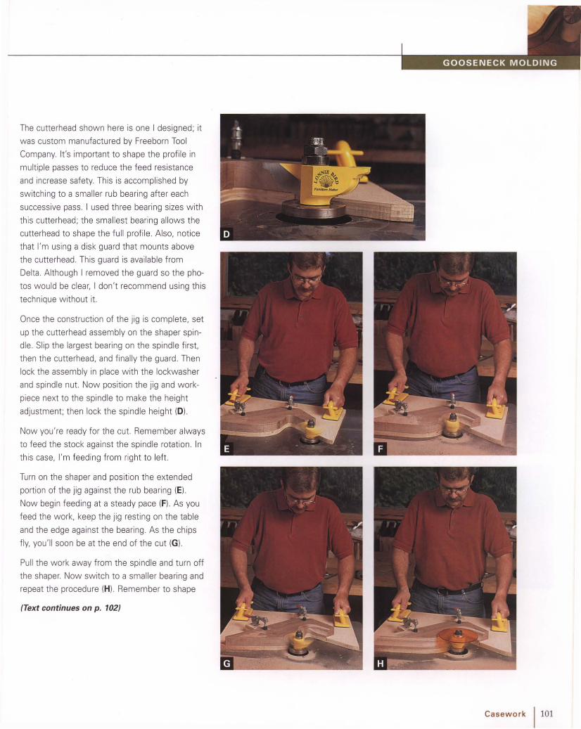
The cutterhead shown here is one I designed; it
was custom manufactured by Freeborn Tool
Company. It's important to shape the prof ile in
multiple passes to reduce the feed resistance
and increase safety. This is accomplished by
switching to a smaller rub bearing after each
successive pass. I used three bearing sizes with
this cutterhead; the smallest bearing allows the
cutterhead to shape the full profile . Also, notice
that I'm using a disk guard that mounts above
the cutterhead. This guard is available from
Delta. Although I removed the guard so the pho
tos would be clear, I don't recommend using this
technique without it.
Once the construction of the jig is complete, set
up the cutte rhead assembly on the shaper spin
dle. Slip the largest bearing on the spindle first,
then the cutterhead, and finally the guard. Then
lock the assembly in place wi th the lockwasher
and spindle nut. Now position the jig and work
piece next to the spindle to make the height
adjustment ; then lock the spindle height (0) .
Now you're ready for the cut. Remember always
to feed the stock against the spindle rotation. In
this case, I'm feeding from right to left.
Turn on the shaper and position the extended
portion of the jig against the rub bearing (E).
Now begin feeding at a steady pace (F). As you
feed the work, keep the jig resting on the table
and the edge against the bearing. As the chips
fly, you'll soon be at the end of the cut (G) .
Pull the work away from the spindle and turn off
the shaper. Now sw itch to a smaller bearing and
repeat the procedure (H). Remember to shape
{Text continues on p. 102}
Casework 1101

102 I Casework
the matching gooseneck each time. Finally, install
the smallest bearing (I) and shape the complete
profi le (J) . Now remove the molding from the jig
and bandsaw the outside curve. Invert the mold
ing and bandsaw from the back for an accurate
cut (K). Next. place the molding into a second jig
for flush trimming (L). This jig has a negative pat
tern that acts as an alignment strip (M).
When you' re finished (N). place the fence around
the cutterhead and shape the returns that miter
to the ends of the gooseneck .

Gooseneck Molding on theRouter Table with Pin JigAnother method for shaping goosenec k and
arched moldings is to use a pin router. A pin or
bearing is suspended over the router, which is
mounted in a table. A template, wh ich is posi
tioned over the stock, follows the guide pin.
Because the pin can be positioned offset to the
router bit, inter ior cuts can be made.
Pilot bearing
r7//#~
~ Router table
Now fasten the wor kpiece to the template wi th
several screws . Take care to keep them out of
the path of the spinning bits. Allow the work to
extend Y.s-in. beyond the template edge for flush
See "Makinga Patten!for aGooseneck Molding"on p. 90.
(Text continues on p. 104)
Although pin routers are expensive, the jig shown
here clamps to the edge of your router table to
convert it to a pin router. A bearing is fastened
to the end of the arm to guide the template (Al .
The arm is held in position on the base w ith a
bolt. A tongue under the arm slides within a
groove in the base to prevent the arm from
moving sideways (8).
After constructing the jig, make a full-size patt ern mof the gooseneck curve. Next, use the pattern to
lay out the curve on both the template and the
stock. Extend the line on the temp late beyond
the curve of the molding. This way the template
will contact the bearing before the router bit con
tacts the stock, eliminating potential grabbing at
the entry of the cut.
Casework 1103

104 Casework
trimming . Next, fasten a large block of the same
thickness toward the back of the template to sta
bilize it as you're shaping. Now you're ready to
begin shaping.
Begin by flush trimming the work (C) with a
flush-trimming router bit (0) ; you wi ll not need
the pin jig for this step. Next, begin shaping the
cove. Because of the large size of the cove, it's
necessary to make this cut in several passes.
Mount the corebox bit in the router and clamp
the jig to the table edge. Now slide the arm of
the jig out and lock it in position for a light cut.
Before starting the cut , you must realize that
it's necessary to keep the template edge in the
same spot on the bearing throughout the cut;
the location is a point tangent to the bearing at
90 degrees to the arm. This is necessary because
the guide bearing and bit are not spinning on the
same axis-they are offset. Performing this task
is not difficult, but requires concentrat ion. Also,
realize that you'll gain experience as you go and
keeping the template located properly is not
extremely critical until the final pass.
Let's give it a try. Turn on the router, position the
end of the template against the bearing, and
begin feeding the stock (E, Fl. As the template
curves, rotate it to maintain contact at the front
of the bearing (G, H, I). Now turn off the router,
retract the arm slightly, and repeat the process
several times until the full profile of the cove has
been shaped (J).

The next step is to shape the ogee at the top of
the molding. If the router bit you're using has a
bearing, you'll first need to remove it and grind off
the stud (K). Now, mount the bit in the router and
adjust the arm to position the bit correctly in rela
tionship to the molding. Now make the cut (L).
The last step is to shape the thumbna il at the
base of the molding (M) . For this profile, you'll
need a bit from CMT USA's crown-molding set.
The inverted profile allows you to shape the
thumbnail on the router table (N) ,
Mitering a GooseneckMolding
Mitering a gooseneck molding is one of those
processes that isn't nearly as difficult as it looks.
The trick is to support the molding on the chop
saw for sawing the miter. To solve the problem ,
simply extend the molding horizontally when
making the pattern . Afte r shaping the molding,
position it on the casework and mark the location
of the miter. Next, align the layout mark with the
kerf on the backboard of the chopsaw (A). Now
clamp the molding in position and make the cut
(8) . Afte r mitering the return, apply glue to each
piece and attach them to the case (e). Photo (D)
shows the molding in place ready for the rosettes
and finials.
Casework 1105

f------- ---------- -------------------
Arched Molding Edgeon the Router TableThe process of shaping a curved strip molding is
much like shaping a straight strip of molding. The
difference is that you'll first have to bandsaw the
curve into the stock (A). Then, when shaping,
you'll guide the workpiece against a bearing
instead of a fence (8).
After shaping, bandsaw the outside radius of the
curved molding and smooth the edges (e) .
& WARNING Remember to use
a starting pin as a fulcrum to enter the
cut safely.
106 Casework

\,
"-- .
-~/'. .
J<----- 21/2 in. dia.------>j
This rosett e is a simple faceplate turn ing (A). To
avoid scarring the work with a screw it's f irst
glued to a scrap of plywood with heavy paper in
the joint. Then the plywood is fastened to the
faceplate wi th screws. After the turning and carv
ing are completed , the glue joint is separated.
Turning a Rosette
Don't sand the turning ; otherwise the fine abra
sive grit will lodge in the pores of the wood and
dull your carving tools. A sharp scraper will leave
the surface relatively smooth; and besides, much
of the surface is carved away.
Before turning, mark the dimensions of the
rosette (8). Next, turn the rosette to diameter
with a parting tool (C). Now you're ready to turn
the beveled shape on the face of the rosette .
Begin by gluing the stock to a scrap of plywood;
'%-in.-thick plywood is suffic ient to screw the
faceplate. Afte r the glue has dried, bandsaw an
oversize circle out of the stock and mount it on
the lathe.
Posit ion the scraper on the tool rest w ith the
edge slightly lowered. This w ill cause the burr on
the scraper to cut clean shavings from the face
of the disk. Now simply pivot the tool side to side
to create the desired shape (0 , E). It's that easy!
Casework 1107

Carving a RosetteA rosette is an ornamental terminus for a goose
neck molding on a pediment. The variations of
this design are numerous. The example shown
here is a small, simple design that is used on
a clock .
Begin by turn ing the rosette on a lathe to the
required shape. Next, step off an even number of
spaces around the perimet er (A) w ith dividers
and make a mark at each division (8) . With the
aid of a center head, draw a line from each divi
sion mark to the hub (C).
With the layout complete, you can turn your
attention to carving. Begin by out lining each lay
out line w ith a V gouge (0 ). The depth of each V
should be greatest at the perimete r and gradually
diminish in size as it reaches the hub (E).
108 I Casework
Next, use a Y.-in. no. 5 gouge to carve the rays
and lobes (F). Begin carving at the perimete r and
work back toward the hub. As you approach the
hub, it will be necessary to carve from the oppo
site direction (G).
You can sand the carving lightly with 240-grit
sandpaper to blend the facets from the gouge.
Use care to avoid sanding away the crisp ridges
on the V's.

Turning a Flame FinialFinials are typically used as embellishment on
casewor k such as clocks, desks , and chests.
After turning the upper port ion of the finial , the
flame is carved.
See "Carving a Flame Finial" on P: 113.
This large finial (A) is easiest to turn as two
pieces. Otherwise the narrow section at the base
of the flame is quite fragile and causes consider
able vibration and difficulty during turning . After
turning and carving the urn and flame , the two
are joined together w ith a round mortise-and
tenon joint.
Begin the urn by turn ing the blank round w ith a
roughing gouge to the largest diameter (8) . For
accuracy, gauge the diameter w ith a spring
caliper. Next, layout the linear measurements
w ith a story stick (e). W ith a parting tool, cut
each of the diameters as indicated on the story
stick (D). With the sizing complete, you're ready
to turn the various shapes.
1- - - - - - - 3/s in..-¥=~::_-----_5/s in.
\;;;;~1------- 1 in.
1_ - - - - - - 3/s in.~:::::;=~-----_13/l6 in.
Casework 1109

110 I Casework
First turn the reverse agee. Scribe a shallow line
with the point of a skew at the start of the agee
(E). This incision will give you a positive start
when shaping the profile . Begin turning by shap
ing the bottom of the agee as a bead (F). Then
turn the top portion as a cove (G) and blend the
two to create a fluid cyma curve (H). Next, turn
the bead at the top, which is adjacent to the fillet
(I). Afterward, remove the extra stock to provide
room to maneuver (J). Then cut the agee at the
top of the turning (K). If necessary, clean up the
fillet to make the surface smooth and the corner
crisp (L, M).
Now shape the bead at the base of the turning
(N) . Then direct your attention to the tiny bead at
the base of the agee. Shaping the bead requires
a delicate touch with the heel of a small skew.
You can gauge the width of this bead with a
small set of dividers . The last profile is the small
cove. Use a small spindle gouge and a light touch
as you shape each side of the cove toward the
bottom (0) . If necessary, sharpen the fillets that
flank the cove w ith a small skew.

Now lightly sand the turning (PI and burnish it
with a handful of shavings (a ); then cut the top
off w ith a parting tool. As you cut the top off
you'll need to support the turning w ith one hand
while controlling the tool w ith the other (R).
The next step is to bore the mortise that accepts
the tenon on the flame. First mount a chuck
equipped with a %-in. bit into the tailstock. Next,
center the bit on the turning and advance it into
the spinning work w ith the handwheel on the
tailstock (5).
To turn the flame, first remove the corners of the
stock with a roughing gouge to the major diame
ter. Next, lay out the linear measurements w ith a
story stick (T) and cut into the final diameters
with a parting tool (U).
The next step is to turn the top of the flame.
Simply approach this convex curve as a bead and
roll it over w ith a spindle gouge (V). Next, shape
(Text continues on p. 112)
"l .:-- ~~, .. I ' ''' ).. , . \ . f. r: ~
; ~ . -~-' .
s ~
Casework 1111

,,. .
~~. 'Il'
- #~:~ . ..'J...;.. ,~i-' "",.:':/ .' ~ ~.~~1~
41\V
. r/,M' . ('
~....,. ,'/. ,. ./Yl ' '.>".. 7?' '.
112 Casewo rk
the tapered lower portion of the flame with a
skew or large spindle gouge (W). Then incise the
width of the bead with the point of a skew (X);
then use the skew to turn the base of the flame
further (V). Next, roll the bead to the left and right
until it is full and round (Z). The last shape is the
small cove under the bead (AA).
After the turning is complete (8 8). cut the round
tenon for a snug fit within the mortise. To check
the tenon for accuracy, make a gauge by boring a
hole in a scrap of thin plywood (CC).
Don't sand the flame turning . If you do, abrasive
grit will lodge in the pores and quickly dull your
carving tools later on. Use a parting tool to cut
the remaining stock from the end of the tenon
and fit it into the mortise in the base (DO).

Line 1=1rotatesone-quarterof a circle.
Six equal
,p"" "topb 1
't;;:::::::::::=;t' Six eq~"0spacesat 1base
Each ridge isa cyma curve.
After turn ing, the next step is to sketch the
design. Good layout allows you to work through
the design details and proportions before you
begin to carve (A ). It also provides an essential
road map to give you direct ion as you're working.
Although seemingly comp lex, the layout for this
finial is relatively easy. It involves repeated ly
sketching cyma CUNes around the perimeter of
the turnin g. Spacing the CUN es is important, too,
but it's easily accomp lished wi th dividers .
See "Turning a Flame Finial" on P: 109.
Carving a Flame FinialFinials are a turned and carved deco ration most
commonly used on the pediments of casework.
The stylized flame finial shown here was a popu
lar ornament on Pennsylvan ia furn iture during the
18"' century. Although smaller fin ials are crafted
from one piece of stock, large finials , such as
this example, are easier to turn in two pieces .
Begin layout by sketching the first curve . It be
comes a ridge that rises from the base and spi
rals one-quarter of the circle as it reaches the
top. Use the lathe dividing wheel to mark the
beginning (B) and end (e) of the curve . It's most
important that the curve is pleasing to the eye,
especially because all the other ridges will be
modeled according to the first one. You' ll f ind it
easier to sketch the CUNe if you pivot the pencil
from your wr ist or the knuckle of your littl e f inger
(0). Just below the midpoint of the turning is the
transition point at which the CUNe changes direc
tion. You'll probably find it easier to invert the
turning to draw the upper portion of the CUNeo
(Text continues on p. 114)
Casework 1113
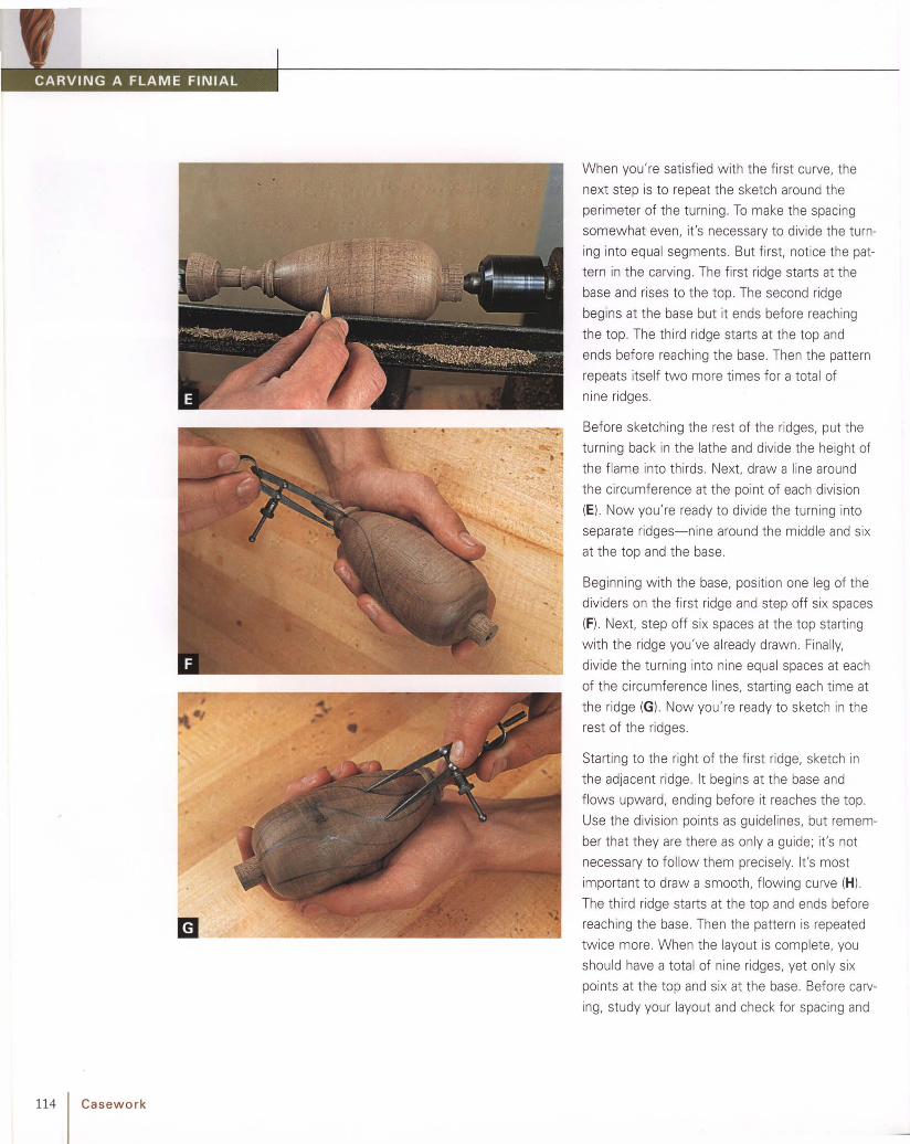
114 Casework
When you're satisfied w ith the first curve, the
next step is to repeat the sketch around the
perimeter of the turning. To make the spacing
somewhat even, it's necessary to divide the turn
ing into equal segments. But first, notice the pat
tern in the carving. The first ridge starts at the
base and rises to the top. The second ridge
begins at the base but it ends before reaching
the top . The third ridge starts at the top and
ends before reaching the base. Then the pattern
repeats itself two more times for a total of
nine ridges.
Before sketching the rest of the ridges, put the
turning back in the lathe and divide the height of
the flame into thirds. Next. draw a line around
the circumference at the point of each division
(E). Now you're ready to divide the turning into
separate ridges-nine around the middle and six
at the top and the base.
Beginning with the base, position one leg of the
dividers on the first ridge and step off six spaces
(F). Next, step off six spaces at the top starting
with the ridge you've already drawn . Finally,
divide the turning into nine equal spaces at each
of the circumference lines, starting each time at
the ridge (G). Now you're ready to sketch in the
rest of the ridges.
Starting to the right of the first ridge, sketch in
the adjacent ridge. It begins at the base and
flows upward, ending before it reaches the top.
Use the division points as guidelines, but remem
ber that they are there as only a guide; it's not
necessary to follow them precisely. It's most
important to draw a smooth, flowing curve (H).
The third ridge starts at the top and ends before
reaching the base. Then the pattern is repeated
twice more . When the layout is complete, you
should have a tota l of nine ridges, yet only six
points at the top and six at the base. Before carv
ing, study your layout and check for spacing and

irregularities in the curves . The layout doesn't
require mechanical precision, but instead the
lines should flow gracefully as they spiral toward
the top. Spacing should look somewhat uniform;
but it doesn 't need to be, nor should it be,
perfect. The idea is to create a carving that is
w ell proport ioned with pleasing curves .
Before you begin carving, take a few minutes
to build the jig shown in photo I (at right) and
photo M (on p. 116). It's essentially a V block
w ith a build-in clamp for securing the work.
A sectional view of the carving reveals a series
of ridges and V's. Each of the cyma curves that
you sketched earlier becomes a ridge; the area
between a pair of ridges forms a V. Carving is
now simply a matter of remov ing the area
between the ridges. And if you keep a couple of
key points in mind as you carve, success is virtu
ally ensured. First, keep the too ls sharp; sharp
ness is critical to control of the tool. I keep a
leather strop on my bench and hone the edges
periodically. Second, always carve w ith or across
the grain, not against it. If you attempt to work
against the grain the wood wi ll splinter and tear.
m
Begin by carving across the grain toward the bot
tom of each V (I). Alternate the cuts from either
side of the V so that the wood between the cuts
is removed cleanly (J) . Work from the center of
the V outward toward the ridges and from the
base of the flame to the tip. Cutt ing across the
grain will leave the surface slight ly coarse; but
the technique removes wood quickly, and you'll
smooth and refine the surface later by carving
w ith the grain.
As you carve, remember that each layout line
becomes a ridge. Also, it's important that the line
formed by the bottom of the V is smooth and
flows in harmony w ith the ridges. As you deepen
each V adjust the line, if necessary, to cause it to
flow smooth ly.
(Text continues on p. 116)
Casework 1115

116 Casework
Avoid carving too deep at first. Once you've
carved the entire circumfe rence of the turning
you' ll have a better feel for the look you're trying
to achieve, and you can deepen the cuts, if nec
essary. Unlike many other areas of woodworking,
carving isn't a process of cutting to a set of pre
cise dimens ions. Instead, it's a matter of creating
balanced, flowing lines. Often the lines can't be
gauged or measured but are judged by a critical
eye. In this case, each line should spiral along its
length in a flowing , uninterrupted cyma curve.
As the carving progresses, the only remaining
portion of the original turned surface will be each
ridge. Be careful to leave the ridges intact
otherwise the flow of the curve that you created
on the lathe w ill be spoiled. The only exception
is the ridges that stop before reaching the base
or the tip. Carve these ridges dow nward at the
ends so that their lines flow smoothly toward
the center of the work (K).
When you're satisfied w ith the initial carving, the
next step is to refine the work. With a 12mm
no. 2 gouge, smooth the surface of each curve
by cutt ing with the grain (L). Sever the end grain
at the base between the flames w ith the point
of a skew.
The final touch is to carve the tiny veins on the
surfaces of the flame . These shallow grooves
break up the otherwise flat surface to give the
carving greater detail and visual interest. But first ,
sketch them in wi th a pencil.
Depending on the w idth of the surface, each has
three to five veins. Using your middle finger as a
gauge, draw each vein beginning wi th the ones
at the outer edges (M ). The veins towa rd the
inside may not flow ent irely from top to bottom
but may fade out as the surface narrows. Then
with a steady hand, carve each vein with a
1.5mm no. 11 gouge (N).

Finial PedestalA router table w ill dramatically increase the ver
satility of your router. Here's a good example.
This small fluted plinth is narrow, wh ich makes it
diff icult to keep the router steady if it's handheld.
Begin with layout. You'll want to be accurate w ith
the spacing, because it's used to set up the
router. Also, mark the position of the end of the
flute (Al . Next, set the cutt ing depth of the bit
and position the fence to cut the center flute .
Finally, set stops at each fence to contro l the
length of the flutes and keep them consistent.
Now you're ready for shaping.
Posit ion the workpiece against the infeed stop
and lower it onto the spinning bit (8). Then push
the stock to the next stop (e ). Feed the stock
slow ly to avoid a fuzzy, torn surface; small
diameter bits have a relatively slow rim speed
even at higher rotations per minute (rpms).
For each successive cut, move the fence closer
to the bit (0 ). For each side of the center flute ,
each fence sett ing w ill make two flutes ; simply
turn the stock end for end.
Casework 1117

Arched Light Sash DoorConst ruct ing a sash-type door with interlocking
bars is a variation on the cope-and-stick con
st ruction. The key is accurate layout and
machine setup .
See "Sash Door Anatomy" on p. 92.
118 Casework
m
Check the fit frequently and make any necessary
adjustments.
Begin by accurate ly milling the stock . Make
the stock for the bars wide enough for two; this
makes feeding the work through machines safer
and more accurate . For greatest accuracy,
clamp matching pieces together and transfer
the lines (A).
The location of the mortise in relationship to the
stick ing is critical. For this reason, shape the
sticking on the stiles first (8). Then cut the mor
tises with a hollow chisel according to the layout
(e). When correctly positioned, the mortise falls
just on the edge of the sticking (D).
Next cut the tenons. Since the tenon shoulders
are offset, cut the face of each tenon (El. and
then adjust the setup for the second shoulder (F).
Before bandsawing the curves, cut the cope on
the tenon shoulder (G). Then bandsaw the arches
in the top rail (H) and smooth them with a spindle
sander.
TI P Remember to check the cope for fit
to the sticking; it may be necessary to
adjust the cutter height, fence position,
or both.

1{4-in. plywoodcap fastened withglue andbrads
Make jig 1{64 in. thinner thanstock to beshaped.
aOnce all the cuts are made, fit each joint individu
ally and check the fit. To assemble the frame
work, fit the sash bars into the rails f irst (M) and
then the stiles. Gently tap the joints together
with a mallet (N). Finally, clamp the door and set
it on a flat surface w hile the glue dries (0 ).
The last two steps are to shape the sticking and
the rabbet. But first you'll need to rip the narrow
sash bars to final w idth . To shape the bars safely,
take a few extra minutes to shape the jig shown
here (I). This jig w ill add much-needed mass to
the otherwise narrow stock (J) . When cutt ing the
second rabbet, fill the first rabbet w ith a stick
tacked into the jig (Kl. To shape the sticking and
to rabbet the arches. it's necessary to use a start
ing pin or block as a fulcrum when entering the
cut (L).
Casework 1119

120 I Casework
Tombstone DoorMitered sticking adds structural strength to a
door because it relies on longer tenons and
deeper mortises than cope-and-stick joinery.
Begin by making an accurate, full-scale drawing
of the door. This provides a layout reference to
use throughout the process. Next, accurately
mill the stock along with an extra piece or two
for testing setups . Then layout, cut, and fit the
mortise-and-tenon joints (A). When laying out the
tenons, add the sticking width to the shoulder at
each end. This will compensate for the sticking
around the mortise, which is removed before
assembly .
The next step is to work the top rail. Begin by
laying out the arch (8). After bandsawing (C),
smooth the curve with a spindle sander (0) .
Now you're ready to shape the frame. Begin by
shaping the sticking profile; first on the top rail
with a starting pin to begin the cut (E) and then
on the stiles and bottom rail with a fence (F).
Next, cut the panel groove using the same
method as used for the sticking profile (G).
Once the sticking and panel grooves are shaped,
you're ready to miter the sticking in the corners.
First, t ilt the table-saw blade to 45 degrees; then
adjust the blade height to cut only the sticking.

Next, mark a vert ical line from the deepest point
of the cut (H). Accuracy of the line is critical to
the fit of the miters.
To use the setup, align the rail shoulders with the
layout line and cut the mite r (I). If you're mitering
several pieces, clamp a thin piece of plywood to
the miter gauge as a stop (J) . To miter the stiles,
align the mortise layout line with the layout line
on the miter gauge (K), Befo re assembling the
frame, you'll need to remove the excess sticking
on the stiles w ith a chisel.
To make the panel, mill it to size and layout the
arch with a compass (L). The radius of the panel
is typically If. in. greater than that of the top rail to
allow for fitt ing into the panel groove.
(Text continues on p . 122)
m
Set bladeheight tosticking width.
Verticalreferenceline
Casework 1121

1----- _
is ready for shaping. Shape the arch first , then
the remainder of the panel (0) .
To create an authentic panel, you'l l need to carve
the inside corners on each side of the arch.
Although it's a bit time-consuming it's not at all
difficult.
First, layout the corner wi th a compass and
square (Pl. Use the compass to complete the
arch into the corner and the square to layout the
shoulder.
The next step is to cut away the excess stock in
the corner (0) . Chisel across the grain to avoid
splitting the panel (R). Next, incise the area indi
cated by the layout line. A chisel wor ks well at
the shoulder, but a carving gouge works best for
the curve of the arch. Check the depth with a
combina tion square to avoid cutting the area too
deep (5) .
With the initial carving done (T), you're ready to
miter the intersec tion . First, incise the miter (U);
then pare the beveled surfaces to the incision
(V). You'll need left- and right-skew ed chisels for
this last stage of the carving.
Finally, sand the panel and assemble the door (W).
122 I Casework

Small Tombstone DoorThe process for making a small tombstone door
is similar to the process for a large door. However,
because the parts are very small, you'll need to
use clamps and jigs to shape them safely.
Always begin with an accurate draw ing, on which
you've wor ked out details and proportions. After
milling the parts of the door, layout the arch in
the rail (A). When bandsawing, fo llow the line
carefully to avoid errors (B).
After smoothing the curve, shape the stick ing
(C) and then the panel groove. When shaping the
curve of the top rail, use a large handscrew,
which safely positions your hands and adds mass
to the part being shaped.
When cutt ing the panel groove in the stile,
remember to start the groove at one mortise and
stop it at the other mort ise (0). This w ill avoid
having a gap in the top of the door frame after
assembly. Use a stop block to prevent kickback.
When milling the short bottom rail, always use a
push block (E).
The next step is to miter the sticking.
With the frame comp lete. you're ready to shape
the panel. The panel-raising bit has a bearing that
follows the curve of the arch (F). To hold the
panel safely w hile shaping, attach it to a push
block wi th double-sided tape (G). This gives you
plenty of leverage w hile distancing your hand
from the router bit.
(Text continues on p. 124)
Casework 1123

• •• • •
124 Casework
TI P 1 When using double-sided tape, usewoodturner's tape, which has tremendous
holding power. Don't be fooled and usecarpet tape. It doesn't work nearly as well.
Apply the tape to the push block and peel the
paper. Then position it on the panel and clamp it
momentarily to strengthen the bond (H).
Shape the arch first (I), which is primarily end
grain; then shape the rest of the panel using a
fence to guide the stock (J). When shaping the
arch, it's crucial to use a pin or block for a fulcrum
when starting the cut. Once the work makes con
tact with the bearing on the bit, it's safe to pivot
away from the starting pin or block. Positioning
the fence for straight cuts is easy; simply align
the fence tangent to the bearing (K).
Finally, carve the corners and assemble the door.

Shapinga Lipped Door EdgeUnlike an overlay door that closes against the
cabinet face, a lipped door looks refined. That's
because most of the door's thickness fits inside
the cabinet and the remaining lip is shaped with
a delicate thumbnail profile.
The example I'm using here is the pendulum door
from the waist of a tall clock. The top of the door
has a decorative cutout. After bandsawing the top
of the door, use a flush-trimming router bit and a
template to remove the bandsaw marks (A). Then
carve the inside corners where the router bit didn't
reach (B). Next. use a roundover bit to shape the
thumbnail profile around the perimeter of the
door (Cl, Set the height of the bit to create a Y.6""in.
fillet next to the thumbnail prof ile. This fillet is
important; it creates another fine detail to capture
light and create a shadow line.
After the thumbnail, shape the rabbet that allows
most of the door to fit within the opening. The
bearing on the rabbeting bit can ride along the
thumbnail without damaging it; just don't press
too hard (0) .
TI P ] A fence can be used to limit therabbet's depth along the straight portionsof the door.
Afterward, carve the inside corners on the top of
the door to complete the thumbnail profile (E).
Casework / 125

It is important to note that the hinged edge of
the door has just a small lip (Y,6in.) to prevent it
from binding on the stile of the case. Also, you
will need to purchase hinges with offset leaves.
For the large doors of the upper case of a secre
tary, I modif ied blank hinges (A) .
Hanging Lipped DoorsLipped doors look refined because most of the
door thickness rests inside the case and the
lipped edge conceals the small gap around the
door. Although they are a bit more work than a
flush-f itting door, the results make it worth the
extra effort.
The first step is to layout the hinge mortise on
the door stile . After marking the height (Bl. posi
tion the hinge and trace the opposite edge (C).
Next, set a marking gauge to equal the hinge
thicknes s (0) and scribe the mort ise depth (E).
Begin mortising by lightly chopping a series of
cuts across the grain (F). Next, pare across the
grain to the mortise depth (G). Install the screws
(H) and fit the door in the case opening to mark
the location on the cabinet stile (I). Cut the mor
tises on the case to complete the job.
126 Casework

Larqe Fluted PilasterFluting lengthy stock, such as this pilaster for a
corner cabinet, can be awkward when passed
across the short top of a router table. In situa
tions such as this, it's much easier to pass the
router over the stock . Before you begin, you'll
need a guide accessory, which attaches to the
base of your router. Or you can make a guide
as I did here (A).
After attaching the guide, adjust the cutt ing
depth of the bit (8). Next, mill the stock for the
pilasters. If you mill it oversize in length, you'll
have an area to lay out the flutes and check each
router sett ing (C).
After layout, clamp a stop block at each end
to keep the flutes uniform in length. Begin by
routing the center flutes and work outward (0).
Afterward, cut two flutes with each new sett ing
(E). Each time you start a new flut e, position the
router base against the stop block (F).
Casework 1127

128 Casework
Carved Reverse-Stop FlutesBefore carving stop flutes, you'll need to modify
the edge of the gouge. Carving gouges are
somewhat square when you buy them . Although
this profile is effective for most types of carving,
the outside corners of the gouge will dig in when
incising a stop flute . Instead, the end of the
gouge must be semicircular to follow the con
tour of the flute .
The most efficient way to change the tool shape
is to use a grinder. Roll the tool from side to side
on the grinding wheel to grind away the corners.
As you grind, keep the tool moving to avoid dead
spots in the curve. After grinding, sharpen the
tool to a mirror surface w ith benchstones .
A reverse-stop flute is a neat detail at the lower
end of a flute . Rather than leave the flute end
concave, as from the router, the end is carved to
a convex prof ile. Like many details that add visual
interest to a piece of furniture, reverse-stop
flutes can't be created by machine. But for a
special piece of furniture, the extra handwork is
worth it.
Begin by routing stop flutes as shown on p. 127.
Be certain to provide space for the carving. Next,
layout the stop flute. Use a combinat ion square
to extend the sides of the flute and a circle tem
plate to draw the arc (A, B).
Now select a carving gouge w ith a sweep that
comes closest to the curve of the arc. Incise the
curve by cutt ing vert ically with the gouge (e ).
Then carve parallel to the flute to complete the
prof ile (D).
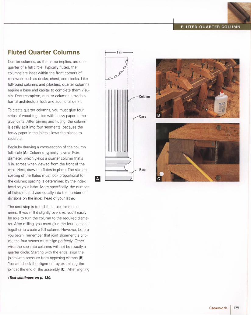
Fluted Quarter ColumnsQuarter columns, as the name implies, are one
quarter of a full circle. Typically fluted, the
columns are inset within the front corners of
casework such as desks, chest. and clocks . Like
full-round columns and pilasters, quarter columns
require a base and capital to complete them visu
ally. Once complete, quarter columns provide a
formal architectural look and additional detail.
To create quarter columns, you must glue four
strips of wood together with heavy paper in the
glue joints. After turning and fluting, the column
is easily split into four segments, because the
heavy paper in the joints allows the pieces to
separate.
Begin by drawing a cross-sect ion of the column
full-scale (A). Columns typically have a 1'% in.
diameter, which yields a quarter column that's
~ in. across when viewed from the front of the
case. Next, draw the flutes in place. The size and
spacing of the flutes must look proport ional to
the column; spacing is determined by the index
head on your lathe. More specifically, the number
of flutes must divide equally into the number of
divisions on the index head of your lathe.
The next step is to mill the stock for the col
umns. If you mill it slightly oversize, you'll easily
be able to turn the column to the required diame
ter. After milling, you must glue the four sections
together to create a full column . However, before
you begin, remember that joint alignment is criti
cal; the four seams must align perfectly. Other
w ise the separate columns will not be exactly a
quarter circle. Starting with the ends, align the
joints w ith pressure from opposing clamps (B).
You can check the alignment by examining the
joint at the end of the assembly (e). After aligning
(Text continues on p . 130)
r-- 1in' -----1
QIIII
V_ COlumn
~ Case
)
I====~.J~ Base'\.;
Casework 1129

130 Casework
the ends, clamp the remainder of the work. For
safety reasons, allow the glue to dry overnight
before turning .
The next step is to turn the square to a uniform
cylinder. Begin by squaring the ends of the turn
ing blank. Then mark the centers for mount ing in
the lathe. Once again, alignment is critical. Mark
the exact location with the point of an awl (0 ).
Afterward, mount the blank securely in the lathe
for turn ing.
Turning a straight. uniform cylinder isn't diff icult if
you follow a few easy steps . First, turn the blank
round w ith a roughing gouge (El. Then carefully
turn it to the required diameter. You can accom
plish this by cutting to the diameter at several
locations with a parting tool. As you lever the tool
into the spinning stock with one hand, gauge the
diameter with spring calipers in the other hand
(F). Then turn the remaining portion of the cylin
der to diameter with the roughing gouge.
Afterward, smooth the cylinder wi th a block
plane. Support the plane on the tool rest and
push it slowly down the length of the slowly
spinning stock (G). This is a great technique!
The plane cleanly shears away the high spots to
create a perfectly smooth , uniform surface (H).

The next step is to rout the flutes . But first you'll
need to build a jig (I). The jig is actually a box that
mounts to the bed of the lathe to support the
router during the fluting process. Next, mount
the box under the workpiece and, if necessary,
attach a square base to your router to fit within
the sides of the box (J) . Finally, set the cutt ing
depth of the bit and lock it in position .
Before you begin routing, remember that the
flutes must be spaced equally around each quar-
ter column; the first and last flute on each quarter
column should be adjacent to a glue joint. For Dthis spacing to occur, it may be necessary to
reposition the cylinder between the centers .
Lock the cylinder in place w ith the pin on the
index head (K); then make a very short test cut
on one end of the cylinder. If the flute falls next
to the glue joint. fine. If not, release the pressure
slightly at the tailstock and rotate the column to
bring the router bit into alignment. Now tighten
the handwheel at the tailstock and make a sec
ond test cut.
Once the column is aligned for the first flute ,
successive flutes will be correctly positioned
in relation to the glue joints. Once the setup is
complete. route the flutes (L). If you choose to
stop the flutes, tack a wood block to the jig to
act as a stop.
When flut ing is complete , remove the column
from the lathe and carefully split it into corners by
placing a w ide chisel at one end and tapping it
gently (M ).
Casework 1131

Section
Section
132 Casework
Reeded TurningReeding is a series of convex semicircular
shapes, used as surface decoration (A). Although
a router bit can be used for reeding, it's effective
only when the surface to be reeded is straight.
Surfaces that swell and taper, such as the exam
ple shown here, must be carved. Think about it
this way : As the reeds flow down a tapered sur
face they must taper too (8). Furthermore, as
they taper, the radius of each reed continually
changes. Although a router guided by a tapered
template w ill shape the reeds, it w ill not created
a truly reeded surface-only a facsimile. This is
because the radius of the router bit profile is
constant.
Begin by turning the leg (C). Next, lay out the
reeds equally around the circumference of the
turning (D).

Screwpinches dowel in kerf.
Pencil
Complete the carving by sanding each reed
lightly to smoot h away any remaining facets from
the gouges.
This is easy to accompl ish with the simple jig
shown here (El. Use the index head on your lathe
to keep the spacing accurate. The next step is to
outline each mark w ith a V gouge. First lock the
turning in position with the pin on the index head.
Then carefully follow each layout line with the
gouge (Fl. Be sure to keep the lines running
straight (G). Now round over the reeds with vari
ous sweeps of carving gouges (H). The wider
portions of each reed will require gouges with a
broader sweep ; narrow areas require a gouge
with a tighter sweep. Work carefully to keep
each reed uniform as it tapers . Once you've
carved each reed, inspect the surfaces for unifor
mity and make any necessary adjustments (I).
Casework 1133

f--------------- - --------- - - - ------
Base and Capital Molding
This small molding forms the base and capital on
the fluted pilasters for a desk interior. After the
str ips are shaped, they are cut into small blocks
and shaped on the ends to complete the detail.
TI P Whenever I design a new molding,
I first make a drawing. It's a great aid forthe setup; I can take measurements
directly from the drawing to set the bitheight. At each setup, I compare the testcut to the drawing to check accuracy.
The first step is to shape the bead. To set the bit
height, I used a molding sample that I saved from
a previous run (A). Shape the bead with the
molding inverted (8). The next step is to lay the
molding face down and shape the large cove at
the top edge (e) . Now turn the molding end for
end, which will posit ion the remaining flat surface
against the fence, and shape the small cove (0) .
Finally, use a straight bit to cut the fillets next to
the small cove (E).
134 Casework

-----------------------------------i~
Shaping the Edge of Baseand Capital MoldingThis small-part setup uses a miter gauge in con
junction w ith a backup board, which is fastened
to the head of the gauge wi th a pair of screws.
The router table fence is first secured parallel to
the miter gauge slot; the small wo rkpiece is then
clamped to the backup board for safe shaping.
The parts being shaped in this example are the
base and capital for a pilaster, or flat column .
After shaping, the complete pilaster is added to
the interior of a desk.
See "Fluted Quarter Columns " on p. 129.
The first stage in this process involves shaping a
strip of molding.
After shaping, short blocks of the molding are cut
from the strip for use as the base and capital (A).
But first. the ends of the blocks must be shaped,
or " returned," with the same profiles used on
the face of the block. This setup allows safe and
accurate shaping of very small workpieces such
as these.
For each profile, orient the stock on the edge (8)
or end (C) and firmly clamp it to the backup board
on the miter gauge.
Casework 1135

Feed
Note: Jig is pictured upside down.
136 Casework
Stockmustfit snug.
Placestockhereforshapingends.
Candle-Slide FrontsThis method uses a simple jig that is designed
for shaping multiple parts, such as the candle
slide front for a desk. The jig is a piece of 'Y.-in.
thick plywood with pockets for holding the wor k
(A). A rabbet holds the first workpiece as it is
shaped along the edge; the second workpiece is
held within a groove as the end is shaped. The
fit of the workpiece within the groove must be
snug; a finger hole in the top of the jig provides a
way to push the work free from the jig after
shaping.
Furthermore, the rabbet that secures the work
for shaping the edge must be slightly less in
dimension than the stock being shaped. This way
pressure is applied to the stock as it is shaped.
preventing chatter.
After making the jig, mill the stock for a snug fit
within the groove of the jig (8). Next, shape the
ends of the stock. Then place it into the rabbet
for shaping an edge. If you are shaping multiple
pieces. you can also position a second piece into
the jig for end shaping (e) . As you use the jig,
maintain firm pressure against the router table
and fence (0).

--------
Index
AAuches, 91, 92-93, 106, 118-19, 120-24Arithmetic progression, 88, 89Armchairs, 64-65, 70-73Astragal profile, 6, 37
BBall-and-claw feet, 24, 42-43, 47-49, 65Bandsaw techniques
for bracket feet, 50-55for chairs, 70-72, 75for curves, 70-72for legs, 27, 34, 44, 75for splars, 66-67
Base and capital molding, 134-35 .Bead profile, 6-8, 11, 16-17, 19, 31, 110Bed posts, 56-62Bracket feet, 43, 50-55
CCabriole legs, 24-25 , 26, 34-35, 42-43,
44,65Candle-slide fronts, 136Carving
ball-and-claw feet, 47-49dentil molding, 23finials, 113-1 6lamb's tongue, 62rosettes, 108shells, 81-84trifid feet, 45-46volutes, 74
Casework, 85-136dividers for, 97-99doors for, 91-93, 118-26joinery for, 89-9 1, 93, 94-95molding for, 8, 88, 90, 100-106,
134-35proportioning, 86, 88, 89
Chairs, 63-84arm and posts for, 64-65, 70-73backs for, 63, 68legs for, 65, 75-78shoes for, 79side rails for, 80splats for, 63-64, 66-69, 79
Chamfer profile, 6, 37, 58, 77, 78Columns, quarter, 129- 31Corner cabinets,S, 88Cove profile, 6, 11,22,79
molding plane for, 15router techniques for, 20table saw techniques for, 18, 19turning, 31, 110
Crown molding,S, 9,10,18-22Curves, 65,66-67, 70-72, 78, 90
compound, 16, 34cyma, 113, 115
DDentil molding, 23Desks, 90-91, 92-93Dished tabletops, 36, 39- 40Dividers, 97-99Doors, 91-93, 118-26Dovetail joints, half-blind, 89- 90, 93, 94-95Drawers, 88, 89, 92, 93D rop leaf tables, 37
FFeet, 42-55
ball-and-claw, 24, 42-43, 47-49, 65bracket, 43, 50-55pad,24,26,42,44trifid (three-toed), 24, 42, 45-46
Finials, 88-89, 109-16, 117Flat bracket feet, 43, 50-51Flat stock molding, 9, 10,20-21,22Flutes, 127-31
GGolden rectangle, 86, 88Gooseneck molding, 88, 90, 100-105
HHalf-blind dovetail joints, 89-90, 93, 94-95Hin ges, 41, 126
JJigs
for candle-slide fronts, 136for dished tabletops, 39-40for finials, 115for gooseneck molding, 100-102for octagonal tapers, 57-58
pin, 103-4for quart er columns, 131sparrnarker's, 57, 61See alsoTemplates
Jointshalf-blind dovetail, 89-90, 93, 94-95miter,S, 105mortise-and-tenon, 64, 80, 111, 112,
118rule, 41
KKnee blocks, 28, 29
LLamb's tongue, 62Legs, 24-35
cabriole, 24- 25, 26, 34-35, 42-43,44, 65
chair, 65, 75- 78feet for, 42-55offset, 26, 32-33ring-and-vase, 25-26tapered, 25, 27, 30-31, 33turned,25-26, 30-33
Lipped doors and drawers, 92, 93,125-26
MMiter joints,S, 105Molding, 4-23, 88
arched, 106base and capital, 134- 35casework, 8, 88, 90, 100-106, 134-35complex, 4, 7-11,22crown, S, 9, 10, 18- 21,22dentil,23flat stock, 9,10,20-21,22gooseneck, 88, 90, 100-105stacked strip, 4- 5, 10, 11, 106tabletop, 37thick stock, 10, 11waist,S, 8, 9
Molding planes, 6, 13, 15, 16, 21, 41Mortise-and-ten on joints, 64, 80, 111,
112,118
Index 1 137

INDEX
138 Index
oO ffset legs, 26, 32- 33a gee profile, 6, 12-14, 37, 110
on bracket feet, 43, 52- 55on gooseneck molding, 105
O ver-the-apron knee blocks, 29O volo profile, S, 6, 11
pPad feet, 24, 26, 42, 44Pedestals, finial, 117Pediment s, 88-89Pencil-post beds, 56- 62Pilasters, S, 93, 127Pin jigs, 103-4Planes, 6, 13-15, 16, 21,41 , 75Proportioning systems, 86, 88, 89
QQjrarter columns, 129- 31Qu irk bead, 6, 16
RRectangle, golden, 86, 88Reeding, 132- 33Resawing, 66-67Returns, 97Ring-and -vase legs, 25- 26Rosettes, 88-89, 107- 8Router techniques
for beveled splats, 69for finial pedestals, 117for flutes, 127for half-blind dovetails, 94-95for legs, 76, 77, 78for molding, 20,103-5,106,134-35for pencil-post beds, 57-60for quarter columns, 131for returns, 97for rule joint s, 41for seatboards, 96for tabletops, 38, 39-40
Rule joint, 41
SSafety, 11,33, 100Sash doors, 91-92,118-1 9Scalloped tabletops, 36-37, 38Scratch stock, 6, 7, 16Scrollwork, 53, 68Shaper techniques, 12, 58-60, 100-102Shell carving, 81-84Shoes, chair, 79Side rails, chair, 80Slant-front desks, 92-93Sparrnaker's jig, 57, 61Splats, 63-64, 66-69, 79Stacked strip molding, 4- 5, 10, 11, 106Stanley #55 plane, 6, 14Stop cuts, 50
TTables, 37Table saw techniques, 18-1 9,50, 55Tabletops, 36- 41Tapered legs, 25,27,30-31,33,56-61Templates, 76, 97, 98, 103-4Thick stock molding, 10, 11Three-to ed feet, 24, 42, 45-46Thumbnail profile, 5-6, 9, 18-2 0, 93, 96,
105, 125Tombstone doors, 91, 92, 120-24Transition blocks, 28- 29Trifid feet, 24, 42, 45-46Turn ing
finials, 109-1 2legs, 25-26, 30-33pad feet, 44quarter column s, 130reeds, 132-33rosettes, 107
uUnder-the-apron knee blocks, 28Universal plane, 6, 14
vVolutes, 74

Related Documents