PERI PERI UP Rosett Flex Working Scaffold 100 with Deck UDI Assembly Instructions for Standard Configuration Edition 08/2008

Welcome message from author
This document is posted to help you gain knowledge. Please leave a comment to let me know what you think about it! Share it to your friends and learn new things together.
Transcript

PERI
PERI UP Rosett Flex Working Scaffold 100 with Deck UDI
Assembly Instructions for Standard Configuration
Edition 08/2008


PERI UP Rosett Flex Working Scaffold 100 with Deck UDI
Contents PERI
Overv iew Introduction General information
Erecting and Dismantl ing Manual
A1 Erecting the base 4 A2 Erecting the first level 6 A3 Erecting further scaffold levels 10 A4 Dismantl ing 13 A5 Material transport manually 14 A6 Anchors 15 A7 Scaffold access 17 A8 Installing supplementary components 19
B1 B2
Load capacity Anchor patterns
25 28
C1 Work safety C2 Assembly w i th guardrail in advance
38 39
Components 42
Key
A Safety Instructions <9> Visual control Hints Site Tips
3 Assembly Instructions for Standard Configuration
PERI UP Rosett Flex Working Scaffold 100 with Deck UDI
Overview PERI
3a
Stairs
1 Adjustable base plate U J B 10b Node brace UBK* 26 Staircase UAS*
2 Collar UVB 24 10c Coupler brace UBC* 27 Stair guardrail UAG*
3 Ledger UH 10d Horizontal brace UBH* 28 Inside stair guardrail
3a Ledger UH 100 11 Console bracket UCM*
4 Reinforced Ledger UHV* 12 Console bracket brace U C M *
5 Standard UVR 13 Wall tie UWT* * (shown later)
6 Top Standard UVH 20 Wall tie UWT*
7 Industrial Deck UDI 21 Latice girder ULS&ULA*
8 Toeboard Steel UPY 22 Starter tube ULB*
9 Hatch UAF 23 Guardrail UPG*
9a Access Deck UAL* 24 Spigot ULT
10a Ledger bracing UBL 25 Guardrail Coupler UPW*
1 Assembly Instructions for Standard Configuration

PERI UP Rosett Flex Working Scaffold 100 with Deck UDI
Introduction PERI
These assembly instructions apply together w i t h Approval Z-8.1-863.
They describe the standard design for facade scaffold according to the provisions set down in DIN 4420-1 as
wel l as the requirements for system scaffolding according to EN 12810 and EN 12811.
Standard configuration system w id th : 100 cm Standard configuration according Key:
to EN 12810 4 = Service Load Class 4 used as work ing scaffold in Load for a scaffold assembly: 24 m high plus (3.00 kN/m2) Classes 1-4 according to DIN 4420-1 max imum spindle extension / internal D = Platforms w i th drop test or brackets at every level / external bra- (suitable as protection scaffold) Load Classes 1-4 according to ckets / bridging / nets / tarpaulins SW09 = Wid th Class 09 (100 cm width) EN 12811-1: 0.75 - 3.00 kN/m2 300 = Bay length < 300 cm
Product designation according H1 = Headroom class bay lengths: to EN 12810: B = w i th cladding facilit ies 50/75/100/125/150/200/250/300 cm LS = vertical access by ladders and
PERI UP Rosett Flex 100 by stairs EN 12810-4D-SW09/300-H1-B-LS
Important safety instructions: The use of PERI UP Rosett Flex 100 is intended only for professional applica-tions in the construct ion sector as facade scaffolding in accordance w i th EN 12810 - 1:2003 (intended use).
Only PERI U P original components complete w i t h the manufacturer's label are to be used. The use of other products and spare parts represents a misapplication w i th associated safety risks.
Any deviation f rom the standard confi-guration when assembling and/or use
present a potential safety risk and the-refore may only be undertaken after a separate risk assessment has been car-ried out by the scaffolding contractor.
Appropriate measures are to be imple-mented regarding operational safety and stabil i ty on the basis of the risk as-sessment (Extension of the assembly instructions as wel l as safety provisions during assembly, e.g. guardrails; proof of stabil i ty using draft and design speci-fications in accordance w i th Approval Z-8.1-863 and taking into account EN 12811-1).
Note: Appropriate proof of stabil i ty can be or-dered f rom PERI, if the risk assessment and measures deriving f rom this are available. For loads f rom other load classes, and for wider scaffolding up to 150 cm, proofs of stabil i ty have already been issued which can be ordered f rom PERI.
Deviations from technically-function-ing instructions, especially assembly sequences, require separate static proof.
Overview These assembly instructions serve as a basis for the compilat ion of a building-related assembly instruction by the scaffolding contractor - these do not however replace this.
The assembly instructions - regulate the intended use - provide the scaffolding contractor
w i th guidance for safe assembly, modif icat ions and dismantl ing
- give details regarding stabil i ty and work ing safety requirements wi th in the f ramework of the standard confi-guration
The assembly instructions are arranged as fol lows: - general information - assembly of the base - assembly of supplementary compo-
nents
Basis Approval Z-8.22-863: "PERI UP Rosett" Modular System
2 Assembly Instructions for Standard Configuration


PERI UP Rosett Flex Working Scaffold 100 with Deck UDI
General information PERI
Technical suitability
PERI UP may only be assembled, modi-fied and dismantled by technically skil-led scaffolding contractors and site per-sonnel who also possess suff ic ient skill and experience (hereafter referred to as "scaffolding contractor").
Stabil i ty requirements The scaffolding contractor has to gua-
rantee on site that the bearing reac-tions of the scaffold can be reliably car-ried in the foundation and anchorage.
The load-bearing capacity of the fixing material be tween the wall t ies and an-chorage must be verif ied for the ancho-ring forces. Proof must be provided by official approval, static calculation or
test loading according to a recognized method.
Load-distributing support, e.g. planks, are to be placed according to the ground condit ions. If several layers are required, planks are to be arranged crosswise.
Condition of the material The material is to be regularly checked for any signs of damage particularly be-fore any assembly takes place. Damaged components must be ex-changed immediately on site and may no longer be used.
Scaffold tubes and couplers for mount ing and bracing Steel tubes and couplers are to be used in the standard configuration as anchors and as bracing for the lattice girders. Steel tubes w i th a 48.3 m m external di-ameter and at least 3.2 m m wall thick-ness according to DIN 4427 as wel l as
couplers according to EN 74 w i th ap-propriate markings are to be used.
Bolted couplers must be t ightened wi th a moment of 50 Nm (corresponds to a force of 20 kg w i th a 25 cm lever arm). Wedge couplers are to be securely fit-ted using a 500 g hammer.
Personal protective equipment against falls from a height When using personal protect ive equip-ment against falls f rom a height, all va-lid standards and safety regulations are to be taken into consideration by the
scaffolding contractor.
Currently, the fol lowing are of particular importance:
- DIN EN 354: Personal protect ive equipment against falls f rom a height; Lanyards
- DIN EN 355: Energy absorbers - DIN EN 360: Retractable type fall
arresters - DIN EN 361: Full body harness - DIN EN 362: Connectors - DIN EN 363: Fall arrest systems
Availability of the assembly instructions These assembly instructions, together (see EN 12811 - 1:2003 (D) Clause w i th the assembly instructions f rom the scaffolding contractor, must be made available for the entire period, f rom the beginning of the assembly work through to the end of dismantl ing and including the service life at the point of use
Additional regulations: The scaffolding contractor must obser-ve all valid laws and safety regulations regarding assembly and use.
Currently, the fol lowing is of particu-lar importance: "Counci l Directive 89/655/EEC of the European Parliament concerning the min imum safety and health require-ments for the use of work equipment by workers at work".
Signs If certain parts of the scaffolding are not ready for use - in particular during assembly, alteration work and dismant-ling - a warning sign restricting access must be clearly displayed, see Sign 1. In addition, it must be made clear by appropriate physical means that the scaffold is not complete and unauthori-zed access to the danger zone is pre-vented.
No entry! Prohfcido peaorl Acai»o inofildol Prolblto I'accetmol
S i g n 1
•lis
After handover, the scaffolding is to be marked in such a way that the intended use is clearly visible e.g. installing Sign 2 at the scaffold access points.
The signs do not replace the inspec-t ion record!
S i g n 2
3 Assembly Instructions for Standard Configuration

PERI UP Rosett Flex Working Scaffold 100 with Deck UDI
A3 Erecting further scaffold levels PERI
Erecting the scaffold must fo l low the sequence described below!
A1.1 Load distributing base area
Always begin erecting at the highest po in t , preferable at an internal corner.
A Sett lement must be avoided! The scaffold must only be erected w i t h load distribution plates on ground or structures capable of w i t h -standing all imposed loads!
Lay the ledgers UH (3) down to deter-mine the length of the surface to be scaffolded. This wi l l fix the distance be tween the adjustable baseplates UJB (1).
A1.2 Adjustable base plates UJB, base plates U J P
Position adjustable base plates UJB (1) or base plates UJP (1) at the ends of the ledgers UH (3).
< 30 cm 100 cm
Adjustable base plates UJB (1) w i th yel-low and red handles can be extended a max imum of 55 and 30 cm respectively.
Is Adjustable base plates TR 38-70/50 (1) can be used instead of adjustable base plates UJB (1). They can be extended to 47 cm.
A1.3 Changes in height and sloping surfaces
Steps, slopes and changes in height can be overcome using longer vertical standards UVR.
ye l low handle
red handle
0 3
UJB 38-50/30 UJB 38-80/55
4 Assembly Instructions for Standard Configuration

PERI UP Rosett Flex Working Scaffold 100 with Deck UDI
A3 Erecting further scaffold levels PERI
A1.4 Collar UVB
Place collar UVB 24 and adjustable base plates UJB at the required distan-ce f rom the wall.
Place the collar UVB 24 (2) over the ad-justable base UJB (1).
Alternatively vertical standards UVR can be fitted directly on the adjustable base plates UJB (1). This reduces the permis-sible extension length in the anchor pat-terns by 26 cm.
A1.5 Ledger UH
Form a base f rame by connect ing the collar UVB 24 (2) transversely w i th the ledger UH 100 (3a) and longitudinally w i th the ledger UH (3).
Ensure all ledgers UH are level by adjusting the adjustable base plates UJB (1). Then securely fix all the wedges using a 500 g hammer.
Place industrial deck UDI (7) on the ledger UH (3a) as an assembly aid to check squareness (see next page for deck assembly).
The decks used at the base are an aid to erection only, they can be removed later. This does not apply to bays where access decks w i th ladders are fitted, in these bays t w o steel decks should be fitted to support the ladder.
5 Assembly Instructions for Standard Configuration
PERI UP Rosett Flex Working Scaffold 100 with Deck UDI
A3 Erecting further scaffold levels PERI
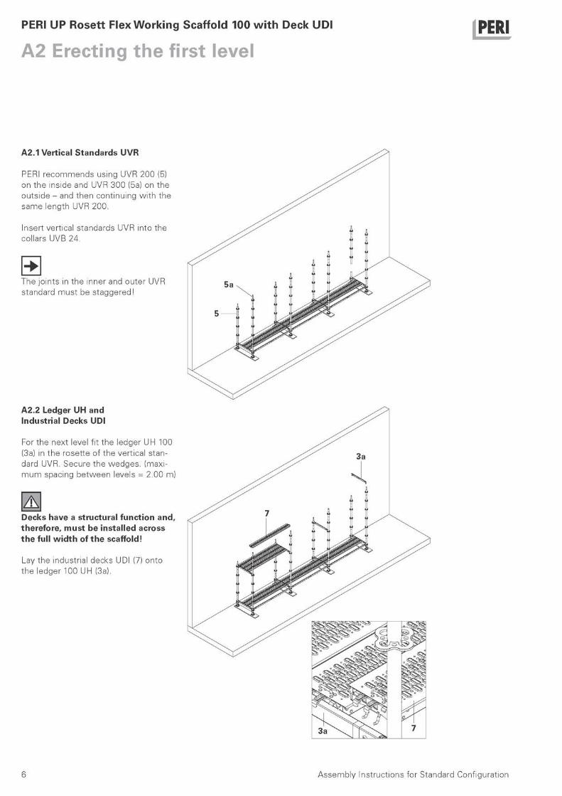
A2.1 Vertical Standards UVR
PERI recommends using UVR 200 (5) on the inside and UVR 300 (5a) on the outside - and then continuing w i th the same length UVR 200.
Insert vertical standards UVR into the collars UVB 24.
The joints in the inner and outer UVR standard must be staggered!
A Decks have a structural function and, therefore, must be installed across the full w i d t h of the scaffold!
Lay the industrial decks UDI (7) onto the ledger 100 UH (3a).
A2.2 Ledger UH and Industrial Decks U D I
For the next level fit the ledger UH 100 (3a) in the rosette of the vertical stan-dard UVR. Secure the wedges. (maxi-m u m spacing between levels = 2.00 m)
l̂ gi ο
SSI
f t
6 Assembly Instructions for Standard Configuration

PERI UP Rosett Flex Working Scaffold 100 with Deck UDI
A3 Erecting further scaffold levels PERI
A2.3 Diagonals
Diagonals are fixed to the outside face of the scaffold at the base and act as bracing.
Either ledger braces UBL (10a) or node braces UBK (10b) can be used.
See anchor pattern for the posit ion and number of diagonals to be fitted.
If node braces UBK are used, the upper ledger UH (3) is not needed.
Ledger Brace UBL
In the bay w i th ledger brace UBL an ad-ditional ledger at deck level is to be in-stalled.
The finger of the ledger diagonal brace UBL (10a) is fitted in the ledger UH (3). The gravity pin is slotted in the hole of the upper ledger UH (3) and is turned to retain it.
N o d e Brace UBK
The node brace UBK (10b) is assembled f rom the outer side of the scaffold. The captive head bolt is lifted and moved over rosette. It must fit completely in the hole of the rosette.
7 Assembly Instructions for Standard Configuration

PERI UP Rosett Flex Working Scaffold 100 with Deck UDI
A3 Erecting further scaffold levels PERI
A2.4 Erecting of further scaffold bays
The erection of all further bays is as previously described.
A2.5 Access deck
Before commenc ing work on the first scaffold l ift, a means of access must be installed.
8 Assembly Instructions for Standard Configuration
PERI UP Rosett Flex Working Scaffold 100 with Deck UDI
A3 Erecting further scaffold levels PERI
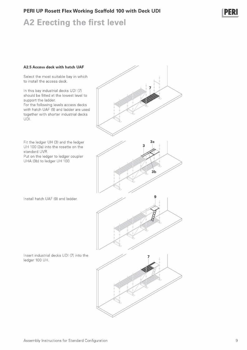
A2.5 Access deck w i t h hatch UAF
Select the most suitable bay in which to install the access deck.
In this bay industrial decks UDI (7) should be fitted at the lowest level to support the ladder. For the fo l lowing levels access decks w i th hatch UAF (9) and ladder are used together w i th shorter industrial decks UDI.
Fit the ledger UH (3) and the ledger UH 100 (3a) into the rosette on the standard UVR. Put on the ledger to ledger coupler UHA (3b) to ledger UH 100.
3a
Install hatch UAF (9) and ladder.
9 Assembly Instructions for Standard Configuration
PERI UP Rosett Flex Working Scaffold 100 with Deck UDI
A3 Erecting further scaffold levels PERI
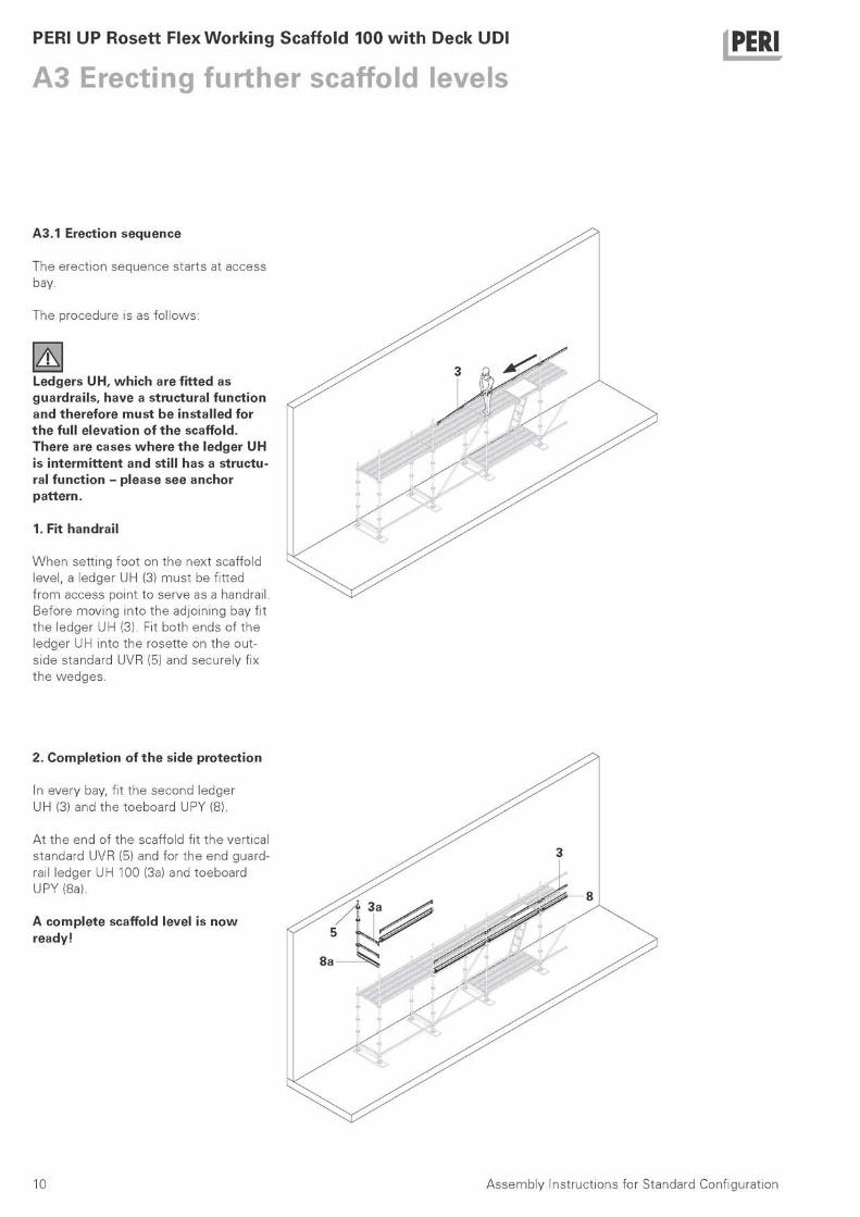
A3.1 Erection sequence
The erection sequence starts at access bay.
The procedure is as fo l lows:
A Ledgers UH, which are fitted as guardrails, have a structural function and therefore must be installed for the full elevation of the scaffold. There are cases where the ledger UH is intermittent and still has a structu-ral function - please see anchor pattern.
1. Fit handrail
When setting foot on the next scaffold level, a ledger UH (3) must be fitted f rom access point to serve as a handrail. Before moving into the adjoining bay fit the ledger UH (3). Fit both ends of the ledger UH into the rosette on the out-side standard UVR (5) and securely fix the wedges.
2. Complet ion of the side protection
In every bay, fit the second ledger UH (3) and the toeboard UPY (8).
At the end of the scaffold fit the vertical standard UVR (5) and for the end guard-rail ledger UH 100 (3a) and toeboard UPY (8a).
A complete scaffold level is now ready!
10 Assembly Instructions for Standard Configuration
PERI UP Rosett Flex Working Scaffold 100 with Deck UDI
A3 Erecting further scaffold levels PERI
A3.1 Erection sequence
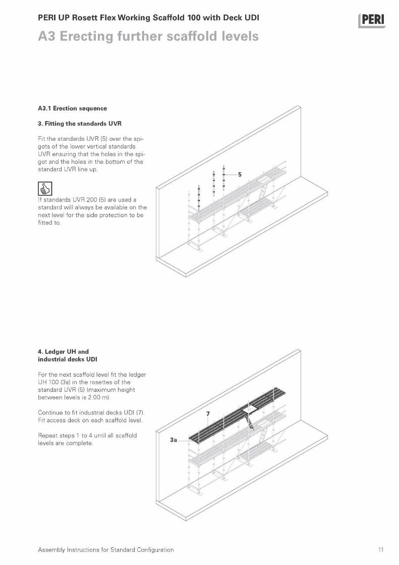
3. Fitting the standards UVR
Fit the standards UVR (5) over the spi-gots of the lower vertical standards UVR ensuring that the holes in the spi-got and the holes in the bot tom of the standard UVR line up.
If standards UVR 200 (5) are used a standard wil l always be available on the next level for the side protect ion to be fitted to.
4. Ledger UH and industrial decks UDI
For the next scaffold level fit the ledger UH 100 (3a) in the rosettes of the standard UVR (5) (maximum height be tween levels is 2.00 m).
Continue to fit industrial decks UDI (7). Fit access deck on each scaffold level.
Repeat steps 1 to 4 until all scaffold levels are complete.
11 Assembly Instructions for Standard Configuration
PERI UP Rosett Flex Working Scaffold 100 with Deck UDI
A3 Erecting further scaffold levels PERI
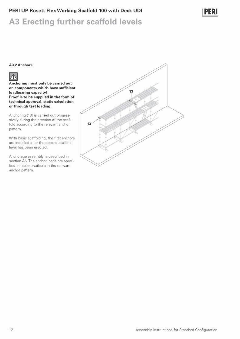
A3.2 Anchors
A Anchoring must only be carried out on components which have sufficient loadbearing capacity! Proof is to be supplied in the form of technical approval, static calculation or through test loading.
Anchoring (13) is carried out progres-sively during the erection of the scaf-fold according to the relevant anchor pattern.
W i t h basic scaffolding, the first anchors are installed after the second scaffold level has been erected.
Anchorage assembly is described in sect ion A6. The anchor loads are speci-fied in tables available in the relevant anchor pattern.
12 Assembly Instructions for Standard Configuration

PERI UP Rosett Flex Working Scaffold 100 with Deck UDI
A4 Dismantling PERI
For dismant l ing, the sequence of wor-king steps described in section A1 - A3 is reversed. Dismantl ing takes place bay by bay whi ls t moving towards the scaffold le-vel access point.
In order to ensure the safety of the scaffolders work ing on the upper levels of the scaffold the fol lowing steps should be adhered to.
Short end - Toeboard UPY (8) - middle ledger UH 100 (3a) - top ledger UH 100 (3a)
Bay length Same sequence as for the short end.
Lower scaffold level: - anchors are removed progressively - Industrial deck UDI (7) and access
hatch - Standard UVR (5) - Ledger UH 100 (3a) - Ledger UH (3) - Toeboard UPY (8)
Working steps are repeated.
Assembly Instructions for Standard Configuration 13

PERI UP Rosett Flex Working Scaffold 100 with Deck UDI
A5 Material transport manually PERI
However, if the scaffold to be erected is not longer than 10.00 m, it is permit ted to erect to a height of 14.00 m wi thout the use of a hoist.
In those bays where materials are to be transported manually, both ledgers UH must be fitted as side protection. When transport ing material manually, a scaf-folder must be posit ioned on each scaf-fold level.
14 Assembly Instructions for Standard Configuration
PERI UP Rosett Flex Working Scaffold 100 with Deck UDI
A6 Anchors PERI
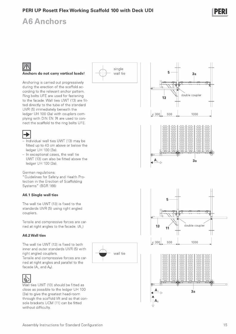
Anchors do not carry vertical loads!
Anchoring is carried out progressively during the erection of the scaffold ac-cording to the relevant anchor pattern. Ring bolts UFE are used for fastening to the facade. Wall t ies UWT (13) are fit-ted directly to the tube of the standard UVR (5) immediately beneath the ledger UH 100 (3a) w i th couplers com-plying w i th DIN EN 74 are used to con-nect the scaffold to the ring bolts UFE.
- Individual wall t ies UWT (13) may be fitted up to 40 cm above or below the ledger UH 100 (3a).
- In exceptional cases, the wall t ie UWT (13) can also be fitted above the ledger UH 100 (3a).
German regulations: "Guidel ines for Safety and Health Pro-tect ion in the Erection of Scaffolding Systems" (BGR 166)
A 6 . 1 Single wal l t ies
The wall t ie UWT (13) is fixed to the standards UVR (5) using right angled couplers.
Tensile and compressive forces are car-ried at right angles to the facade. (A J
A6.2 Wall t ies
The wall t ie UWT (13) is fixed to both inner and outer standards UVR (5) w i th right angled couplers. Tensile and compressive forces are car-ried at right angles and parallel to the facade (A± and An).
Wall t ies UWT (13) should be fitted as close as possible to the ledger UH 100 (3a) to give the greatest head-room through the scaffold lift and so that con-sole brackets UCM (11) can be fitted w i thout diff iculty.
15 Assembly Instructions for Standard Configuration

PERI UP Rosett Flex Working Scaffold 100 with Deck UDI PER|
A6 Anchors
A6.3 Triangulated anchors
Two wall t ies UWT (13) are fixed at an angle of 45° to the ledger line w i th right angled couplers.
They can either: - both be connected to the standard
UVR (5) w i th right angled couplers or - the first wall t ie UWT (13) connected
to the standard UVR (5) and the se-cond wall t ie UWT connected to the first wall t ie UWT at 90° both connec-t ions w i th right angled couplers.
Triangulated anchors carry tensi le and compressive forces at right angles and parallel to the facade (A ' i and A'M).
— ^ — Triangulated anchors
A6.4 Pressure-resistant t ies
The wall t ie UWT (13) is fixed to the standard UVR (5) w i th a right angled coupler. The tube end, w i thout a hook, is positi-oned against the facade.
This arrangement can only carry com-pressive forces at right angles to the facade (AJ.
16
X pressure-resistant t ies
13
30
1 d o u b l e c o u p l e r
< 3 0 0 5 0 0 1 0 0 0
= ο ο ο = = = =
= = = = = ==c^= ===== = = = = =
= = = = = = = = = = = = = = = = = = = =
ο°ο°ο
=0=0°
13 A,
Assembly Instructions for Standard Configuration 16
5

PERI UP Rosett Flex Working Scaffold 100 with Deck UDI
A7 Scaffold access PERI
Before commenc ing work on the first scaffold lift, a means of access must be installed.
A Alternate the direction of the ladders for each level! When the ladder ac-cess is not being used the access hatch must remain closed.
A7.1 Internal access deck w i t h hatch UAF
Select the most suitable bay in which to install the access, preferably the end bay.
In this bay industrial decks UDI (7) should be fitted at the lowest level to support the ladder. For the fo l lowing levels access decks w i th hatch UAF (9) and ladder are used together w i th shorter industrial decks UDI.
17 Assembly Instructions for Standard Configuration
PERI UP Rosett Flex Working Scaffold 100 with Deck UDI
A7 Scaffold access PERI
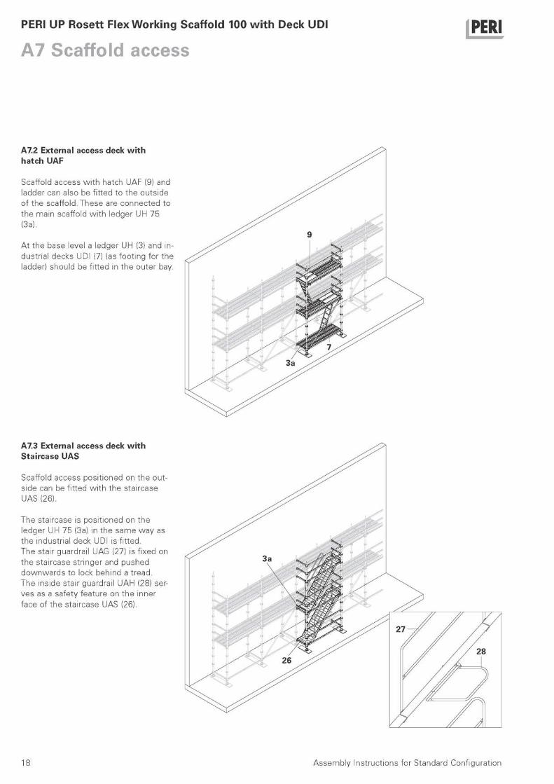
A7.2 External access deck w i t h hatch UAF
Scaffold access w i th hatch UAF (9) and ladder can also be fitted to the outside of the scaffold. These are connected to the main scaffold w i th ledger UH 75 (3a).
At the base level a ledger UH (3) and in-dustrial decks UDI (7) (as foot ing for the ladder) should be fitted in the outer bay.
A7.3 External access deck w i t h Staircase UAS
Scaffold access posit ioned on the out-side can be fitted w i th the staircase UAS (26).
The staircase is posit ioned on the ledger UH 75 (3a) in the same way as the industrial deck UDI is fitted. The stair guardrail UAG (27) is fixed on the staircase stringer and pushed downwards to lock behind a tread. The inside stair guardrail UAH (28) ser-ves as a safety feature on the inner face of the staircase UAS (26).
18 Assembly Instructions for Standard Configuration
PERI UP Rosett Flex Working Scaffold 100 with Deck UDI
A8 Installing supplementary components PERI
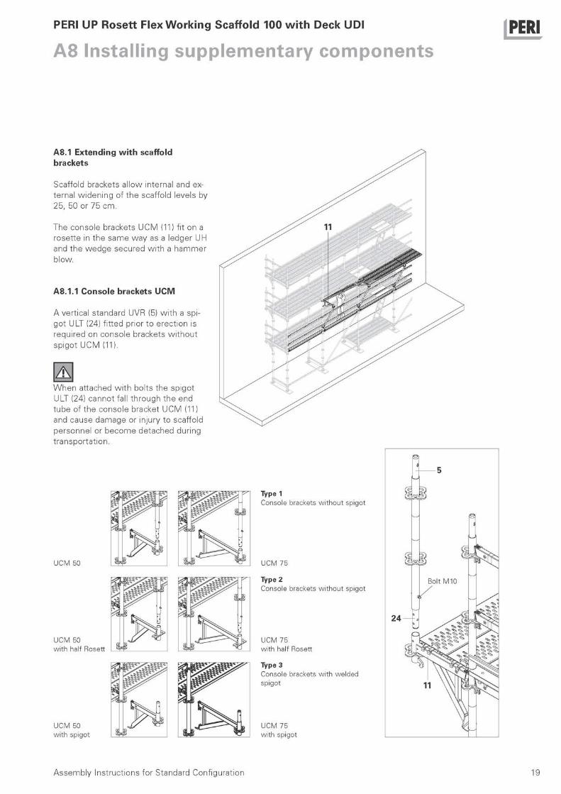
A8.1 Extending w i t h scaffold brackets
Scaffold brackets al low internal and ex-ternal widening of the scaffold levels by 25, 50 or 75 cm.
The console brackets UCM (11) fit on a rosette in the same way as a ledger UH and the wedge secured w i th a hammer blow.
A8.1.1 Console brackets U C M
A vertical standard UVR (5) w i th a spi-got ULT (24) fitted prior to erection is required on console brackets w i thout spigot UCM (11).
A When attached w i th bolts the spigot ULT (24) cannot fall through the end tube of the console bracket UCM (11) and cause damage or injury to scaffold personnel or become detached during transportat ion.
U C M 5 0
U C M 5 0
w i t h ha l f R o s e t t
U C M 5 0
w i t h s p i g o t
Type 1 C o n s o l e b r a c k e t s w i t h o u t s p i g o t
U C M 7 5
Type 2 C o n s o l e b r a c k e t s w i t h o u t s p i g o t
U C M 7 5 w i t h ha l f R o s e t t
Type 3 C o n s o l e b r a c k e t s w i t h w e l d e d
s p i g o t
24
U C M 7 5 w i t h s p i g o t
Assembly Instructions for Standard Configuration 19

PERI UP Rosett Flex Working Scaffold 100 with Deck UDI PER|
A8 Installing supplementary components
A8.1.2 Console brackets U C M and Console bracket brace U C M
The console brackets UCM (11) can, ac-cording to use and loads, be used w i th or w i thout the console bracket brace UCM (12).
Fit console bracket UCM (11) ously described.
as previ-
To fit the console bracket brace UCM (12) first loosen the bolt to the attached half swivel coupler. Insert the spigot into the console bracket tube and then turn the console bracket brace UCM un-til the lug locates under the hook. Then fix the console bracket brace UCM to the vertical standard UVR (5) using the attached half swivel coupler.
o 11
ο
o 11
f i
/ 7 ^ ~ 1 2
20 Assembly Instructions for Standard Configuration
PERI UP Rosett Flex Working Scaffold 100 with Deck UDI PER|
A8 Installing supplementary components
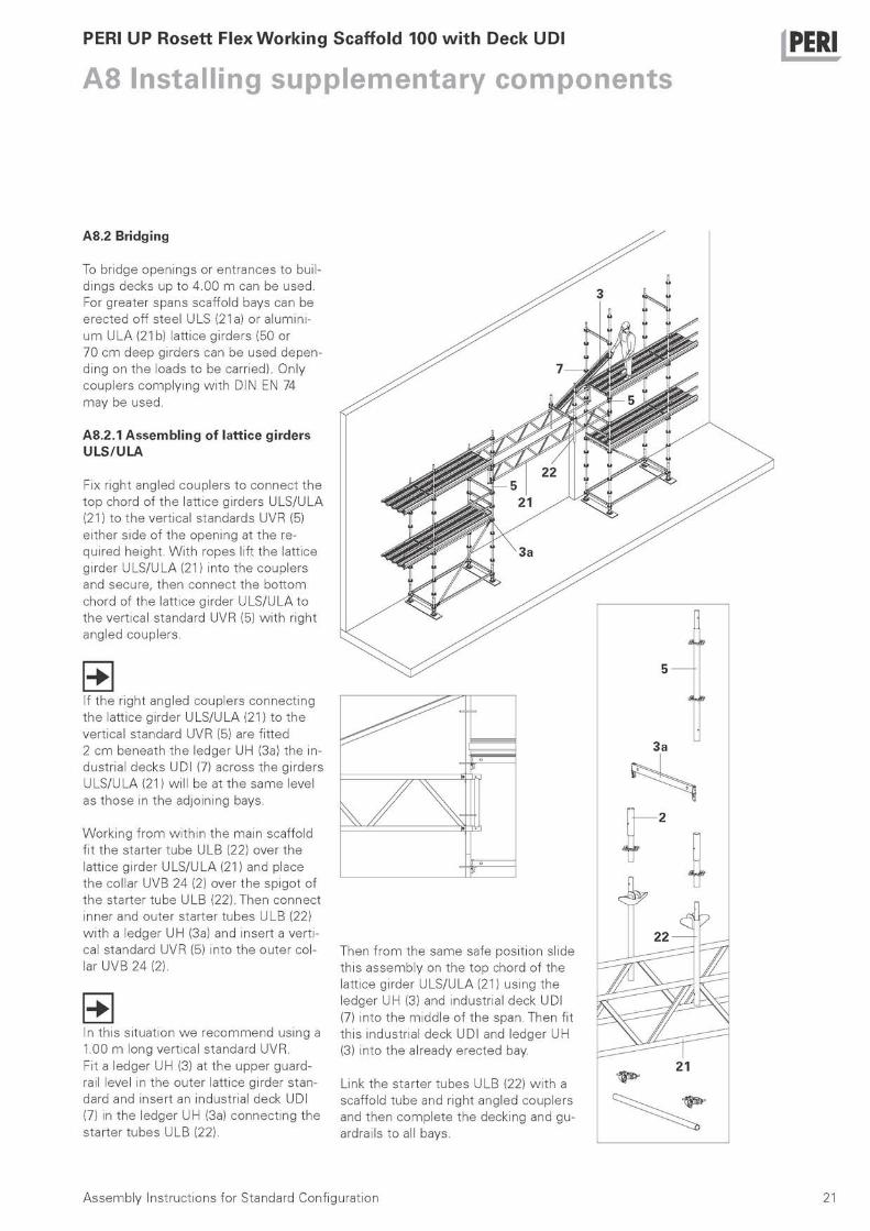
A8.2 Bridging
To bridge openings or entrances to buil-dings decks up to 4.00 m can be used. For greater spans scaffold bays can be erected off steel ULS (21a) or alumini-um ULA (21b) lattice girders (50 or 70 cm deep girders can be used depen-ding on the loads to be carried). Only couplers complying w i th DIN EN 74 may be used.
A8.2.1 Assembling of lattice girders ULS/ULA
Fix right angled couplers to connect the top chord of the lattice girders ULS/ULA (21) to the vertical standards UVR (5) either side of the opening at the re-quired height. Wi th ropes lift the lattice girder ULS/ULA (21) into the couplers and secure, then connect the bot tom chord of the lattice girder ULS/ULA to the vertical standard UVR (5) w i th right angled couplers.
If the right angled couplers connect ing the lattice girder ULS/ULA (21) to the vertical standard UVR (5) are fitted 2 cm beneath the ledger UH (3a) the in-dustrial decks UDI (7) across the girders ULS/ULA (21) wil l be at the same level as those in the adjoining bays.
Working f rom wi th in the main scaffold fit the starter tube ULB (22) over the lattice girder ULS/ULA (21) and place the collar UVB 24 (2) over the spigot of the starter tube ULB (22). Then connect inner and outer starter tubes ULB (22) w i th a ledger UH (3a) and insert a verti-cal standard UVR (5) into the outer col-lar UVB 24 (2).
In this situation w e recommend using a 1.00 m long vertical standard UVR. Fit a ledger UH (3) at the upper guard-rail level in the outer lattice girder stan-dard and insert an industrial deck UDI (7) in the ledger UH (3a) connect ing the starter tubes ULB (22).
Then f rom the same safe posit ion slide this assembly on the top chord of the lattice girder ULS/ULA (21) using the ledger UH (3) and industrial deck UDI (7) into the middle of the span. Then fit this industrial deck UDI and ledger UH (3) into the already erected bay.
Link the starter tubes ULB (22) w i th a scaffold tube and right angled couplers and then complete the decking and gu-ardrails to all bays.
21 Assembly Instructions for Standard Configuration
PERI UP Rosett Flex Working Scaffold 100 with Deck UDI PER|
A8 Installing supplementary components
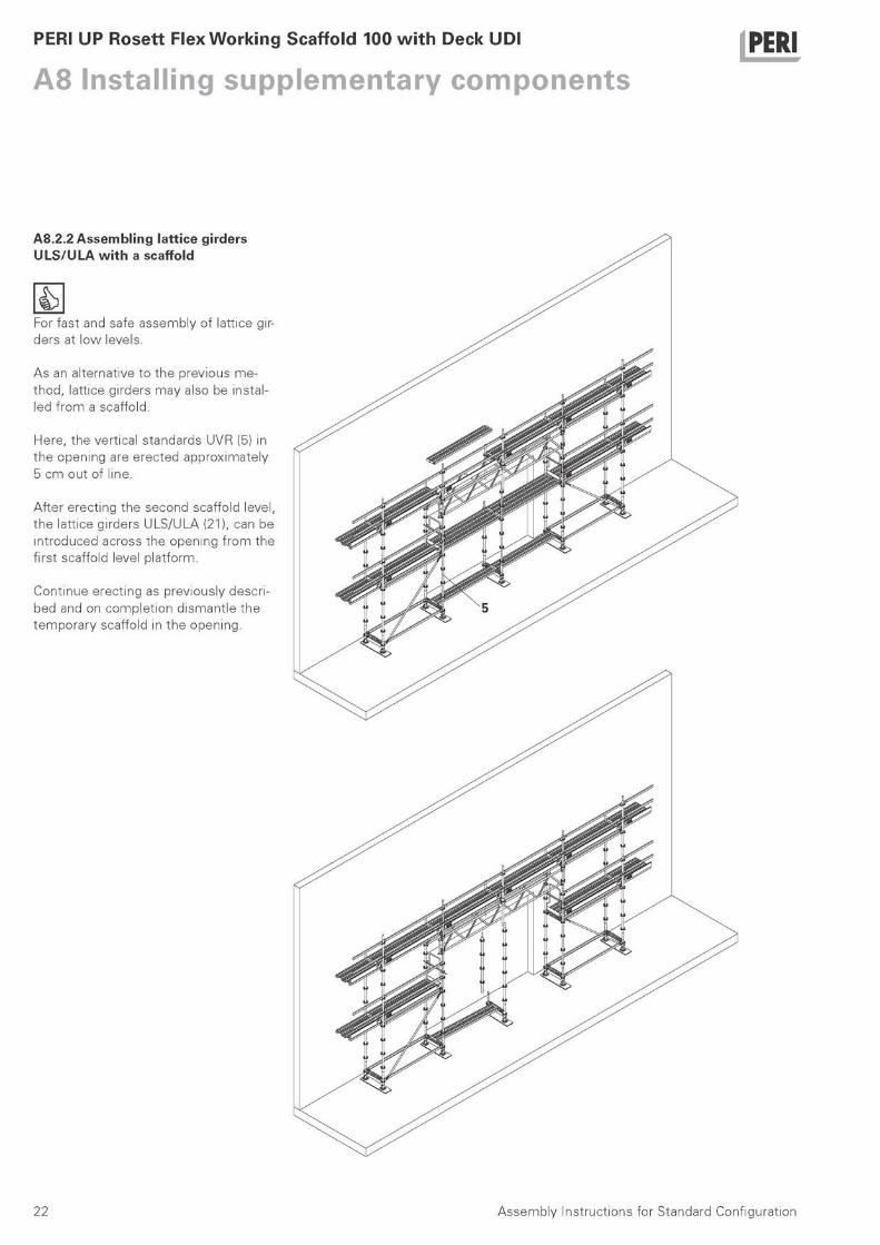
A8.2.2 Assembling lattice girders ULS/ULA w i t h a scaffold
For fast and safe assembly of lattice gir-ders at low levels.
As an alternative to the previous me-thod, lattice girders may also be instal-led f rom a scaffold.
Here, the vertical standards UVR (5) in the opening are erected approximately 5 cm out of line.
After erecting the second scaffold level, the lattice girders ULS/ULA (21), can be introduced across the opening f rom the first scaffold level platform.
Continue erecting as previously descri-bed and on complet ion dismantle the temporary scaffold in the opening.
22 Assembly Instructions for Standard Configuration
PERI UP Rosett Flex Working Scaffold 100 with Deck UDI PER|
A8 Installing supplementary components
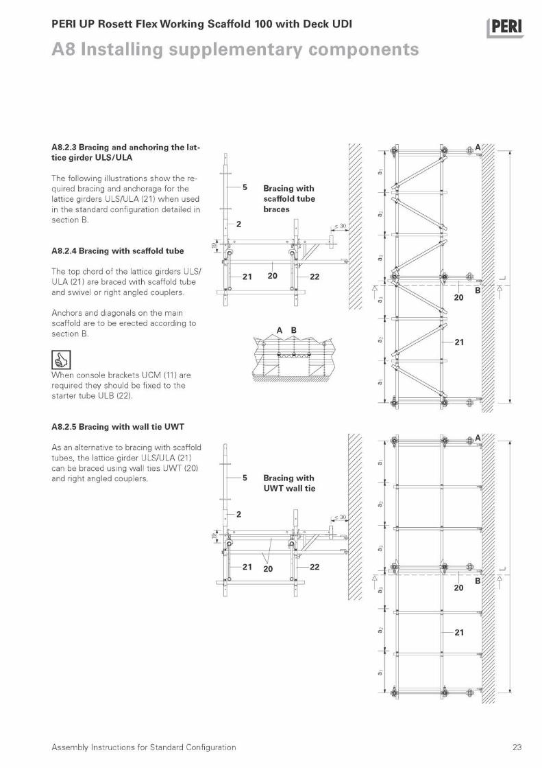
A8.2.3 Bracing and anchoring the lat-t ice girder ULS/ULA
The fol lowing il lustrations show the re-quired bracing and anchorage for the lattice girders ULS/ULA (21) when used in the standard configuration detailed in sect ion B.
A8.2.4 Bracing w i t h scaffold tube
The top chord of the lattice girders ULS/ ULA (21) are braced w i th scaffold tube and swivel or right angled couplers.
Anchors and diagonals on the main scaffold are to be erected according to sect ion B.
i s When console brackets UCM (11) are required they should be fixed to the starter tube ULB (22).
A B
A8.2.5 Bracing w i t h wal l t ie U W T
As an alternative to bracing w i th scaffold tubes, the lattice girder ULS/ULA (21) can be braced using wall t ies UWT (20) and right angled couplers.
JS S5k Λ A r / / γ V/
π
CO*
^
a?
/ / / -1
20 B Ρ Γ
CO1
=T
21
π?
1 2
23 Assembly Instructions for Standard Configuration
PERI UP Rosett Flex Working Scaffold 100 with Deck UDI PER|
A8 Installing supplementary components
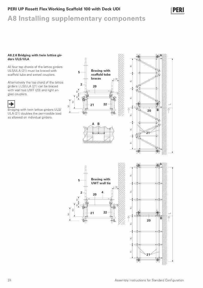
A8.2.6 Bridging w i t h t w i n lattice gir-ders ULS/ULA
All four top chords of the lattice girders ULS/ULA (21) must be braced w i th scaffold tube and swivel couplers.
Alternatively the top chord of the lattice girders ULS/ULA (21) can be braced w i th wall t ies UWT (20) and right an-gled couplers.
Bridging w i th tw in lattice girders ULS/ ULA (21) doubles the permissible load as al lowed on individual girders.
Bracing w i t h scaffold tube braces
•I. ι
Bracing w i t h U W T wal l t ie
20
21 22
20
21
A
5
2
5
30
4 2
24 Assembly Instructions for Standard Configuration
PERI UP Rosett Flex Working Scaffold 100 with Deck UDI
B2 Anchor patterns PERI
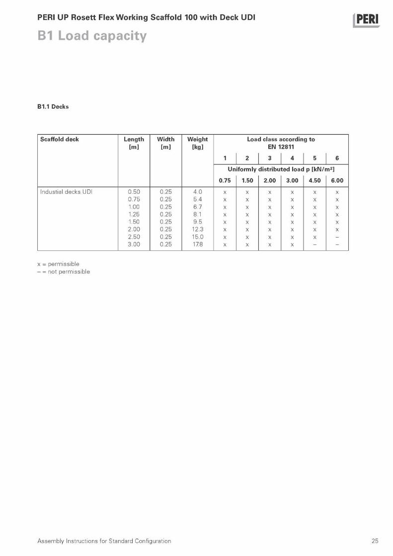
B1.1 Decks
Scaffold deck Length Width Weight Load class according to [m] [m] [kg] EN 12811
1 2 3 4 5 6
Uniformly distributed load p [kN /m 2 ]
0.75 1.50 2.00 3.00 4.50 6.00
Industial decks UDI 0.50 0.25 4.0 x x x x x x 0.75 0.25 5.4 x x x x x x 1.00 0.25 6.7 x x x x x x 1.25 0.25 8.1 x x x x x x 1.50 0.25 9.5 x x x x x x 2.00 0.25 12.3 x x x x x x 2.50 0.25 15.0 x x x x x -3.00 0.25 17.8 x x x x - -
x = permissible - = not permissible
Assembly Instructions for Standard Configuration 25

PERI UP Rosett Flex Working Scaffold 100 with Deck UDI
B2 Anchor patterns PERI
B1.2 Lattice girders
...
ν D
Steel lattice girder ULS
Aluminium lattice girder
ULA HD
Type Spacing of girder bracing Centre point load
End chord connection
Centre point load
End chord connection
Depth / Length a1 a2 as
perm. F bo t tom/ top
perm. F bo t tom/ top
[cm/cm] [cm] [cm] [cm] [kN] [ - ] [kN] [ - ] Span L = 400 cm
50/425 200 - - 15.1 NK/NK 6.3 NK/NK
50/525 200 - - 15.1 NK/NK 6.3 NK/NK
70/525 200 - - 20.7 NK/NK - -
50/425 100 100 - 30.7 NK/NK 16.3 NK/NK
50/525 100 100 - 30.7 NK/UNK 16.3 NK/NK
70/525 100 100 - 31.1 NK/UNK - -
Span L = 500 cm
50/525 250 - - 15.1 NK/NK 6.3 NK/NK
50/625 250 - - 15.1 NK/NK 6.3 NK/NK
50/525 150 100 - 27.2 NK/NK 15.6 NK/NK
50/625 150 100 - 27.4 UNK/NK 15.6 NK/NK
70/525 250 - - 20.7 NK/NK - -
70/625 250 - - 20.7 NK/NK - -
70/525 150 100 - 29.1 UNK/NK - -
70/625 150 100 - 29.1 UNK/NK - -
Span L = 600 cm
50/625 300 - - 8.8 NK/NK 3.5 NK/NK
70/625 300 - - 12.1 NK/NK - -
70/825 300 - - 12.1 NK/NK 5.0 NK/NK
50/625 100 100 100 23.2 NK/NK 13.1 NK/NK
70/625 100 100 100 26.8 NK/UNK - -
70/825 100 100 100 26.6 NK/UNK 15.9 NK/NK
Span L = 800 cm
50/425 400 - - 5.4 NK/NK 2.2 NK/NK
50/425 4 x 100 22.5 NK/NK 13.2 NK/NK
Span L = 800 cm Two single loads at distance of 250 cm from the supports
70/825 250 300 250 2 x 6.0 NK/NK 2 x 2.5 NK/NK
70/825 2x125 + 3x100 + 2x125 2 x 14.6 UNK/NK 2 x 8.2 NK/NK
NK: Right angled coupler class B, EN 74 (SWL 9 kN) UNK: Right angled coupler w i th a check coupler class BB (15kN)
26 Assembly Instructions for Standard Configuration 26

PERI
27 Assembly Instruct ions for Standard Conf igurat ion
PERI UP Rosett Flex Working Scaffold 100 with Deck UDI
B2 Anchor patterns PERI
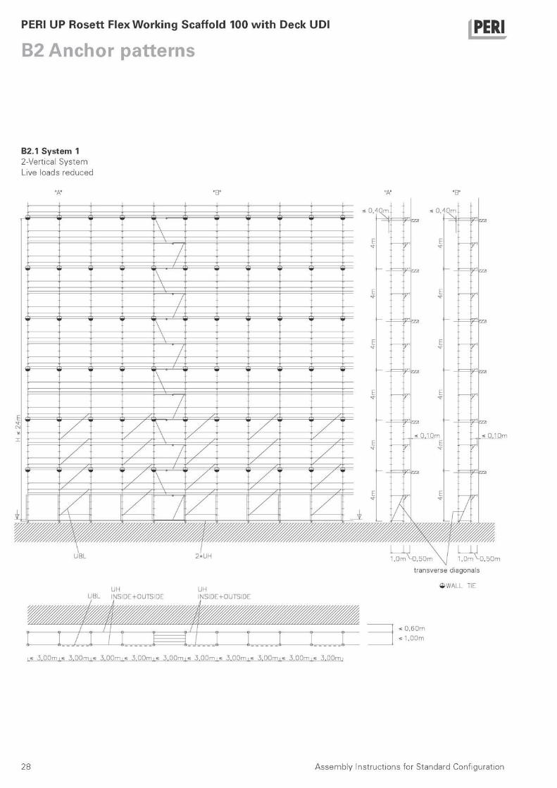
B2.1 System 1 2-Vertical System Live loads reduced
"A" "A"
U B L
UH U B L I N S I D E + O U T S I D E
2 * U H
UH N S I D E + O U T 5 I D E
« η l ( l m « η fflm \
Χ' ' r
Ε
!ZZ
Ε
IZ2
Ε ^
F1
' \
r Ε
!ZZ
Ε
IZ2
Ε ^
F1 ' \
r Ε
!ZZ
Ε
IZ2
Ε ^
F1 r Ε
!ZZ
Ε
IZ2
Ε ^
F1
/
r Ε
!ZZ
Ε
IZ2
Ε ^
F1 r Ε
!ZZ
Ε
IZ2
Ε ^
F1
V • ^
r
Ε
!ZZ
Ε
IZ2
Ε ^
Η r
' \
^
r
Ε
!ZZ
Ε
IZ2
Ε ^
Η r
' \
^
r
Ε
!ZZ
Ε
IZ2
Ε ^
Η r
^
r
Ε
!ZZ
Ε
IZ2
Ε ^
Η r
/
^
r
Ε
!ZZ
Ε
IZ2
Ε ^
Η r
^
r
Ε
!ZZ
Ε
IZ2
Ε ^
Η r
X · ^
Ε
!ZZ
Ε
IZ2
Ε ^
Η \
^
Ε
!ZZ
Ε
IZ2
Ε ^
Η — A
^
Ε
!ZZ
Ε
IZ2
Ε ^
Η /
Ε
!ZZ
Ε
IZ2
Ε ^ /
/ /
Ε
!ZZ
Ε
IZ2
Ε ^ /
r
/
Ε
!ZZ
Ε
IZ2
Ε ^ /
ν • y1
F 1
Ε
!ZZ
< 0 , 1 0 m
V1
F 1
' \
y1
F 1
Ε
!ZZ
< 0 , 1 0 m
V1
F 1 ' \
y1
F 1
Ε
!ZZ
< 0 , 1 0 m
V1
F 1
y1
F 1
Ε
!ZZ
< 0 , 1 0 m
V1
F 1
/
y1
F 1
Ε
!ZZ
< 0 , 1 0 m
V1
F 1
/ ' / / / /
y1
F 1
Ε
!ZZ
< 0 , 1 0 m
V1
F 1
/ ' / / ' ' / ^
Ε
!ZZ
< 0 , 1 0 m
Η ' / ' / ' / ' /
^
Ε
!ZZ
< 0 , 1 0 m
Η / T / • / / /
r Ε
!ZZ
Ε
^ / / ' / / / r Ε
!ZZ
Ε
^ X X / X X X
r Ε
!ZZ
Ε
^ / 3 ^ / / /
r Ε
!ZZ
Ε
^
/ X · / / - X
Ε
!ZZ
Ε
Η / X \ X X X
Ε
!ZZ
Ε
Η ^ ^ —\ / ^ ^
Ε
!ZZ
Ε
Η
ψ \
Ε
!ZZ
Ε /
ψ \
Ε
!ZZ
Ε /
; 0 . 1 0 m
l 0 m M ) , 5 0 m \ J 1 , 0 m M ) , 5 0 m
t r a n s v e r s e d i a g o n a l s
$ W A L L TIE
: 0 , 6 0 m
: 1 , 0 0 m
5 , 0 0 m ι < 5 , 0 0 m ι < 5 , 0 0 m ι < 5 , 0 0 m ι < 5 , 0 0 m ι < 5 , 0 0 m ι < 5 , 0 0 m ι < 5 , 0 0 m ι < 5 , 0 0 m ι < 3 . 0 0 m
Assembly Instructions for Standard Configuration 28

PERI UP Rosett Flex Working Scaffold 100 with Deck UDI
B2 Anchor patterns PERI
Live Loads acc. to UK
load class perm. live load w id th bay length w i th inside brackets
4 300 kg/m2
100 cm < 300 cm 50 cm
Requirements - 4 m anchor pattern - open fagade (100%) - max height < 24 m - inside brackets wi thout bracket brace - wall t ies connect ing inner and outer
vertical - at bottom:
ledgers UH running through at inside and outside
- diagonals in every second bay up to 8.5 m height
- ledgers UH at deck level at the inside
M a x i m u m base plate extension Loading Data out of service condition Loading Data service condition
< 0 .35 m 0 . 7 5 k N / m 2 -
Support Reactions max. F = 21.00 kN
Anchor Forces max. A I I = 1.00 kN max. A 1 = 2.40 kN
Working Load at one Level only
Incidental Load at one
f Level only
3 . 0 0 k N / m 2 Working 0 . 7 5 k N / m 2 Load at o n e
Level only
0 . 7 5 k N / m 2
τ
Incidental Load at one Level only
Assembly Instructions for Standard Configuration 29
PERI UP Rosett Flex Working Scaffold 100 with Deck UDI
B2 Anchor patterns PERI
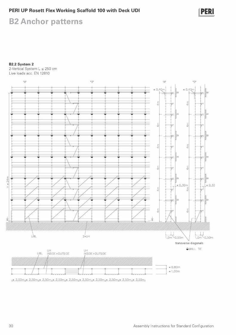
B2.2 System 2 2-Vertical System L < 250 cm Live loads acc. EN 12810
"A" "A"
U B L
UH U B L I N S I D E + O U T S I D E
2 * U H
UH N S I D E + O U T 5 I D E
« η l ( l m Λ « η m m \
Ε
E ^
Ε ^
Ε
< 0 , 3 0 m
V 1
r Ε
E ^
Ε ^
Ε
< 0 , 3 0 m
Χ
' \
r Ε
E ^
Ε ^
Ε
< 0 , 3 0 m
Χ ' \
r Ε
E ^
Ε ^
Ε
< 0 , 3 0 m
Χ r Ε
E ^
Ε ^
Ε
< 0 , 3 0 m
Χ
/ r
Ε
E ^
Ε ^
Ε
< 0 , 3 0 m
Χ r Ε
E ^
Ε ^
Ε
< 0 , 3 0 m
Χ
X · ^ r
Ε
E ^
Ε ^
Ε
< 0 , 3 0 m
r
' \
^ r
Ε
E ^
Ε ^
Ε
< 0 , 3 0 m
r ' \
^ r
Ε
E ^
Ε ^
Ε
< 0 , 3 0 m
r
^ r
Ε
E ^
Ε ^
Ε
< 0 , 3 0 m
r
/
^ r
Ε
E ^
Ε ^
Ε
< 0 , 3 0 m
r
^ r
Ε
E ^
Ε ^
Ε
< 0 , 3 0 m
r
X ·
Ε
E ^
Ε ^
Ε
< 0 , 3 0 m
\
Ε
E ^
Ε ^
Ε
< 0 , 3 0 m
— \
Ε
E ^
Ε ^
Ε
< 0 , 3 0 m
/
Ε
E ^
Ε ^
Ε
< 0 , 3 0 m
/
/ /
Ε
E ^
Ε ^
Ε
< 0 , 3 0 m
/ /
Ε
E ^
Ε ^
Ε
< 0 , 3 0 m
/
X ' r
Ε
E ^
Ε ^
Ε
< 0 , 3 0 m
r
• \
r
Ε
E ^
Ε ^
Ε
< 0 , 3 0 m
r ' \
r
Ε
E ^
Ε ^
Ε
< 0 , 3 0 m
r r
Ε
E ^
Ε ^
Ε
< 0 , 3 0 m
r
f
r
Ε
E ^
Ε ^
Ε
< 0 , 3 0 m
r
/ ' / / / /
r
Ε
E ^
Ε ^
Ε
< 0 , 3 0 m
r
/ ' / / ' ' /
Ε
E ^
Ε ^
Ε
< 0 , 3 0 m ' / ' / ' / ' /
Ε
E ^
Ε ^
Ε
< 0 , 3 0 m / T / • / / / Ε
Ε
/ / ' / / / Ε
Ε
/ / / / / /
Ε
Ε
/ 3 ^ / / /
Ε
Ε
/ X · / / - X
Ε
Ε / / \ / / /
Ε
Ε ^ ^ —\ / ^ ^
Ε
Ε
ψ /
Ε
Ε /
\ ψ /
Ε
Ε /
0 , 3 0
l 0 m M ) , 5 0 m \ j 1 , 0 m M ) , 5 0 m
t r a n s v e r s e d i a g o n a l s
$ W A L L TIE
: 0 , 8 0 m
: 1 , 0 0 m
2 , 5 0 m ι < 2 , 5 0 m ι < 2 , 5 0 m ι < 2 , 5 0 m ι < 2 , 5 0 m ι < 2 , 5 0 m ι < 2 , 5 0 m ι < 2 , 5 0 m ι < 2 , 5 0 m ι < 2 . 5 0 m
Assembly Instructions for Standard Configuration 30
PERI UP Rosett Flex Working Scaffold 100 with Deck UDI
B2 Anchor patterns PERI
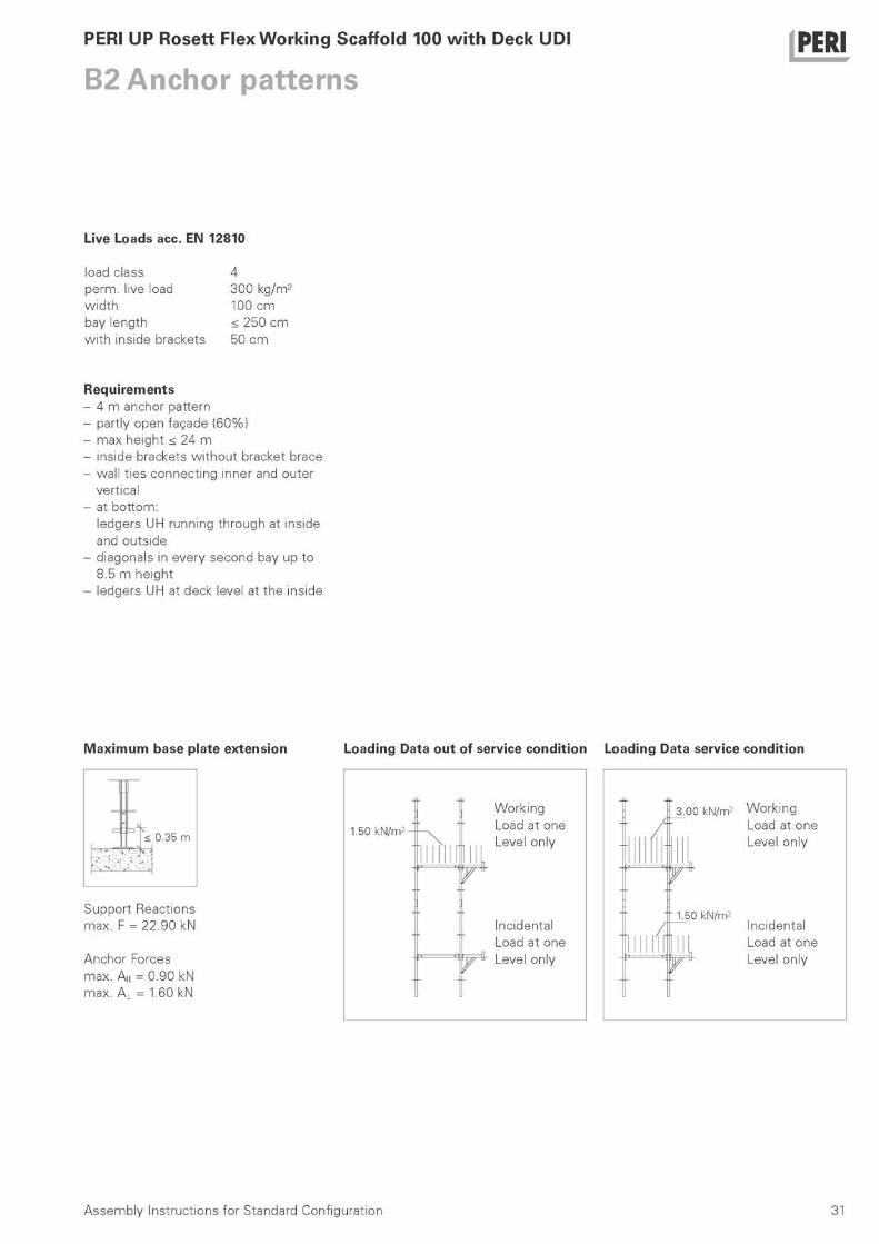
Live Loads acc. EN 12810
load class perm. live load w id th bay length w i th inside brackets
4 300 kg/m2
100 cm < 250 cm 50 cm
Requirements - 4 m anchor pattern - partly open fagade (60%) - max height < 24 m - inside brackets wi thout bracket brace - wall t ies connect ing inner and outer
vertical - at bottom:
ledgers UH running through at inside and outside
- diagonals in every second bay up to 8.5 m height
- ledgers UH at deck level at the inside
M a x i m u m base plate extension Loading Data out of service condition Loading Data service condition
< 0 . 3 5 m 1.50 k N / m 2 -
Support Reactions max. F = 22.90 kN
Anchor Forces max. A I I = 0.90 kN max. A 1 = 1.60 kN
Working Load at one Level only
Incidental Load at one
" ψ ^ Level only
3 . 0 0 k N / m 2 Working Load at one Level only
1.50 k N / m 2
Τ
Incidental Load at one Level only
Assembly Instructions for Standard Configuration 31

PERI UP Rosett Flex Working Scaffold 100 with Deck UDI
B2 Anchor patterns PERI
B2.3 System 3 2-Vertical System L < 300 cm Live loads acc. EN 12810
"A"
UH U B L I N S I D E + O U T S I D E
UH N S I D E + O U T 5 I D E
"A"
0 . 5 0 m
0 m v 0 , 2 5 m
t r a n s v e r s e d i a g o n a l s
^ W A U U TIE
: 0 , 5 5 m
: 1 , 0 0 m
3 , 0 0 m i < 3 . 0 0 m i s 3 , 0 0 m i < 3 , 0 0 m i < 5 , 0 0 m i < 3 . 0 0 m i < 3 , 0 0 m i < 3 , D 0 m i < 5 , 0 0 m i < 3 , 0 0 m
Assembly Instructions for Standard Configuration 32
PERI UP Rosett Flex Working Scaffold 100 with Deck UDI
B2 Anchor patterns PERI
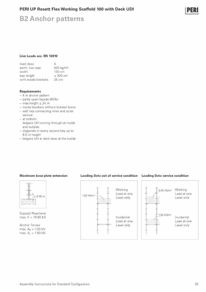
Live Loads acc. EN 12810
load class perm. live load w id th bay length w i th inside brackets
4 300 kg/m2
100 cm < 300 cm 25 cm
Requirements - 4 m anchor pattern - partly open fagade (60%) - max height < 24 m - inside brackets wi thout bracket brace - wall t ies connect ing inner and outer
vertical - at bottom:
ledgers UH running through at inside and outside
- diagonals in every second bay up to 8.5 m height
- ledgers UH at deck level at the inside
M a x i m u m base plate extension Loading Data out of service condition Loading Data service condition
< 0 . 3 5 m
Support Reactions max. F = 19.80 kN
Anchor Forces max. A I I = 1.00 kN max. A± = 1.80 kN
3 . 0 0 k N / m 2 Working Load at one
| Level only
" 1 . 5 0 k N / m 2
Incidental Load at one
^ Level only
Assembly Instructions for Standard Configuration 33
PERI UP Rosett Flex Working Scaffold 100 with Deck UDI
B2 Anchor patterns PERI
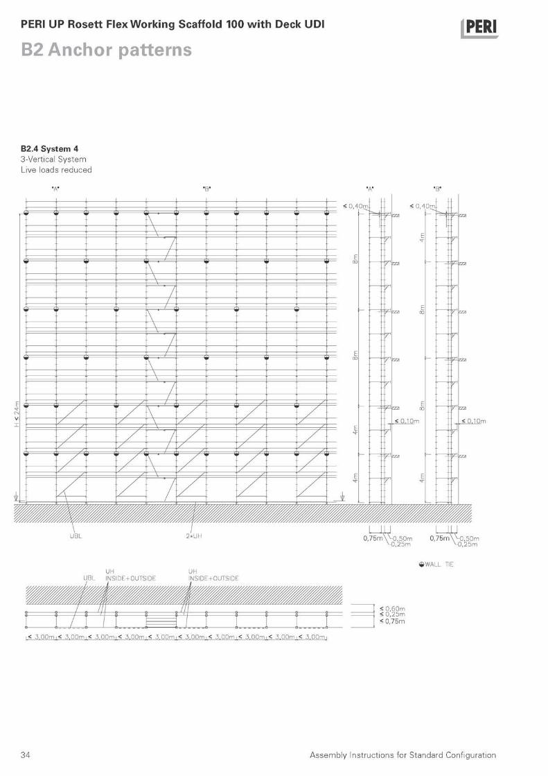
B2.4 System 4 3-Vertical System Live loads reduced
UH UBL I N S I D E + O U T S I D E
UH N S I D E + O U T S I D E
< 3 , 0 0 m ι < 3 , 0 0 m ι < 3 , 0 0 m i < 3 , 0 0 m i < 3 , 0 0 m i < 3 . 0 0 m i < 3 . 0 0 m i < 3 . 0 0 m i < 3 . 0 0 m i < 3 . 0 0 m
^ W A L L TIE
< 0 , 6 0 m < 0 , 2 5 m < 0 , 7 5 m
Assembly Instructions for Standard Configuration 34
PERI UP Rosett Flex Working Scaffold 100 with Deck UDI
B2 Anchor patterns PERI
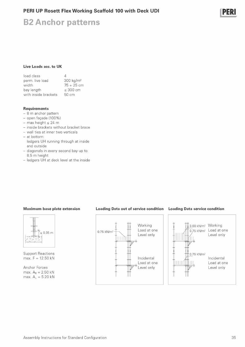
Live Loads acc. to UK
load class perm. live load w id th bay length w i th inside brackets
4 300 kg/m2
75 + 25 cm < 300 cm 50 cm
Requirements - 8 m anchor pattern - open fagade (100%) - max height < 24 m - inside brackets wi thout bracket brace - wall t ies at inner t w o verticals - at bottom:
ledgers UH running through at inside and outside
- diagonals in every second bay up to 8.5 m height
- ledgers UH at deck level at the inside
M a x i m u m base plate extension Loading Data out of service condition Loading Data service condition
< 0 . 3 5 m 0 . 7 5 k N / m 2 -
Support Reactions max. F = 12.50 kN
Anchor Forces max. A I I = 2.50 kN max. A 1 = 5.20 kN
Working Load at one
-|4 Level only
Ύ
incidental Load at one
y Level only
γ
3 . 0 0 k N / m 2 Working 0 . 7 5 k N / m 2 Load at one / Level only
incidental Load at one Level only
0 . 7 5 k N / m 2
τ
Assembly Instructions for Standard Configuration 35
PERI UP Rosett Flex Working Scaffold 100 with Deck UDI
B2 Anchor patterns PERI
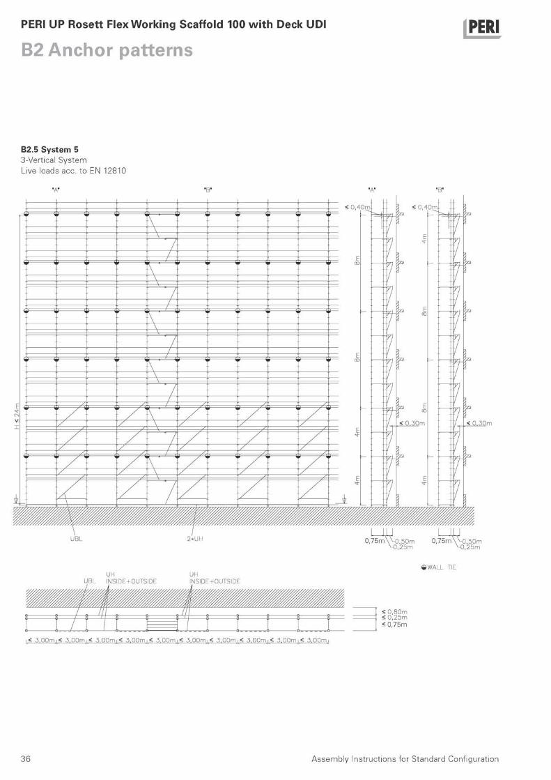
B2.5 System 5 3-Vertical System Live loads acc. to EN 12810
< 0 . 3 0 m
2 * U H 0 , 7 5 m \ ^ 0 , 5 0 m 0 , 7 5 m \ H 3 , 5 0 m , 2 5 m M ) , 2 5 m
UH UBL I N S I D E + O U T S I D E
UH N S I D E + O U T S I D E
< 0 , 8 0 m < 0 , 2 5 m < 0 , 7 5 m
^ W A L L TIE
< 5 , 0 0 m ι < 3 , 0 0 m ι < 3 , 0 0 m i < 5 , 0 0 m i < 3 , 0 0 m i < 3 . 0 0 m i < 5 . 0 0 m i < 5 . 0 0 m i < 5 . 0 0 m i < 5 . 0 0 m
Assembly Instructions for Standard Configuration 36

PERI UP Rosett Flex Working Scaffold 100 with Deck UDI
B2 Anchor patterns PERI
Live Loads acc. to EN 12810
load class perm. live load w id th bay length w i th inside brackets
4 300 kg/m2
100 cm < 300 cm 50 cm
Requirements - 4 m anchor pattern - partly open fagade (60%) - max height < 24 m - inside brackets w i th bracket brace - wall t ies connect ing inner and outer
vertical - at bottom:
ledgers UH running through at inside and outside
- diagonals in every second bay up to 8.5 m height
- ledgers UH at deck level at the inside
M a x i m u m base plate extension
< 0 . 3 5 m
Loading Data out of service condition Loading Data service condition
3 . 0 0 k N / m 2 Working Load at one Level only
Support Reactions max. F = 17.30 kN
Anchor Forces max. A I I = 2.50 kN max. A 1 = 5.20 kN
1.50 k N / m 2
Incidental Load at one
'Υ I Level only
Assembly Instructions for Standard Configuration 37
PERI UP Rosett Flex Working Scaffold 100 with Deck UDI
B2 Anchor patterns PERI
C1.1 Basic requirements
The scaffold assembly al lows for strin-gent safety measures to prevent the risk of falling during assembly, adjusting and dismantl ing wo rk as far as they are recognisable and can be planned on the basis of a risk analysis.
• In order to guarantee the provision of safety against falling, the scaffold contractor has to carry out a site-specific risk evaluation for each scaf-fold assembly and for each use of the scaffolding; based on this, he is obli-ged to implement appropriate safety measures against falling.
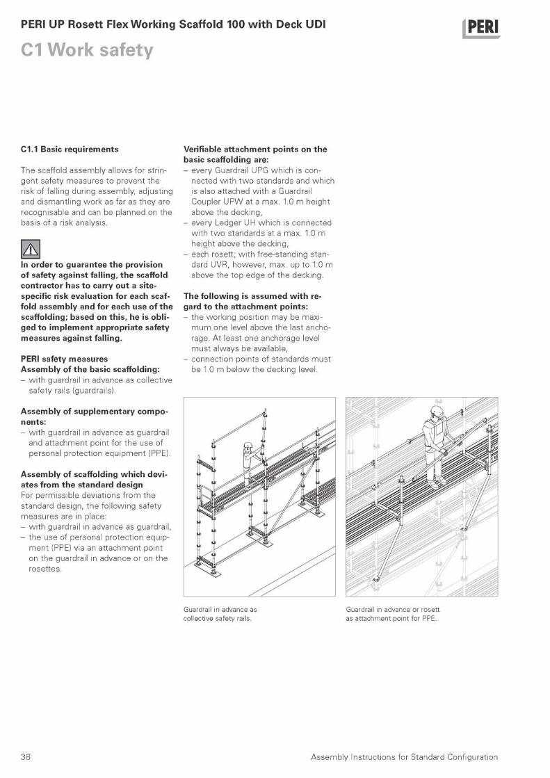
PERI safety measures Assembly of the basic scaffolding: - w i th guardrail in advance as collective
safety rails (guardrails).
Assembly of supplementary compo-nents: - w i th guardrail in advance as guardrail
and attachment point for the use of personal protect ion equipment (PPE).
Assembly of scaffolding which devi-ates from the standard design For permissible deviations f rom the standard design, the fol lowing safety measures are in place: - w i th guardrail in advance as guardrail, - the use of personal protect ion equip-
ment (PPE) via an attachment point on the guardrail in advance or on the rosettes.
Verifiable at tachment points on the basic scaffolding are: - every Guardrail UPG which is con-
nected w i th t w o standards and which is also attached wi th a Guardrail Coupler UPW at a max. 1.0 m height above the decking,
- every Ledger UH which is connected w i th t w o standards at a max. 1.0 m height above the decking,
- each rosett; w i th free-standing stan-dard UVR, however, max. up to 1.0 m above the top edge of the decking.
The fol lowing is assumed w i t h re-gard to the attachment points: - the work ing position may be maxi-
m u m one level above the last ancho-rage. At least one anchorage level must always be available,
- connect ion points of standards must be 1.0 m below the decking level.
G u a r d r a i l in a d v a n c e as
c o l l e c t i v e s a f e t y ra i ls .
G u a r d r a i l in a d v a n c e or r o s e t t
as a t t a c h m e n t p o i n t f o r PPE.
38 Assembly Instructions for Standard Configuration 38

PERI UP Rosett Flex Working Scaffold 100 with Deck UDI
C2 Assembly with guardrail in advance PERI
C2.1 Erecting the first level
PERI recommends for the use of the guardrail in advance start ing w i th verti-cal standards UVR 200 (5) on the inside and UVR 300 (5a) on the outside - and then always continuing wi th UVR 200 (5).
Insert vertical standards UVR 200 (5) at the inside into the collars UVB 24 (2). Fit guardrail coupler UPW (25) in the top rosette of the vertical standard UVR 300 (5a). Secure the wedge. Place UVR 300 at outside into collar UVB 24.
Connect ledger UH (3a) to the rosettes of verticals. Secure wedges.
Place the first guardrail UPG (23) on the pin of guardrail coupler UPW (25) at the already erected vertical.
Fit guardrail coupler UPW (25) in the top rosette of the next vertical standard UVR 300 and securely fix the wedge. Attach the other end of the guardrail to the vertical standard UVR 300 and then lift and place UVR 300 at outside into collar UVB 24.
Install industrial decks UDI, fit hatch UAF as access in most suitable bay and continue until scaffold level is complete.
When setting foot on the next scaffold level the side protect ion must be com-pleted. In every bay, fit ledgers UH as lower guardrails and toeboards UPY. At the end of the scaffold fit the vertical standard UVR 200 and for the end gu-ardrail ledger UH and toeboard UPY. A complete scaffold level is now ready!
39 Assembly Instructions for Standard Configuration

PERI UP Rosett Flex Working Scaffold 100 with Deck UDI
C2 Assembly with guardrail in advance PERI
C2.2 Erecting further levels
Fit vertical standard UVR 200 (5) at the inside over the spigots of the lower ver-tical standards ensuring that the holes in the spigot and the holes in the bot-t o m of the standard line up. Fit guardrail coupler UPW (25) in the top rosette of the vertical standard UVR 200 (5). Secure the wedge. Place UVR 200 at outside.
Attach ledger UH (3a) and secure wedges.
Connect guardrail UPG (23) to guardrail coupler UPW (25).
Fit guardrail coupler UPW (25) to next vertical standard UVR 200 and securely fix the wedge. Attach guardrail UPG (23) to vertical standard UVR 200 (5) and place vertical standard at outside.
Install industrial decks UDI, fit hatch UAF as access in most suitable bay and continue until scaffold level is complete.
Repeat steps until all scaffold levels are complete.
40 Assembly Instructions for Standard Configuration

PERI
41 Assembly Instruct ions for Standard Conf igurat ion
100863 Accessories
1,030 Handle Lock UJS, galv. (1 Pcs.)
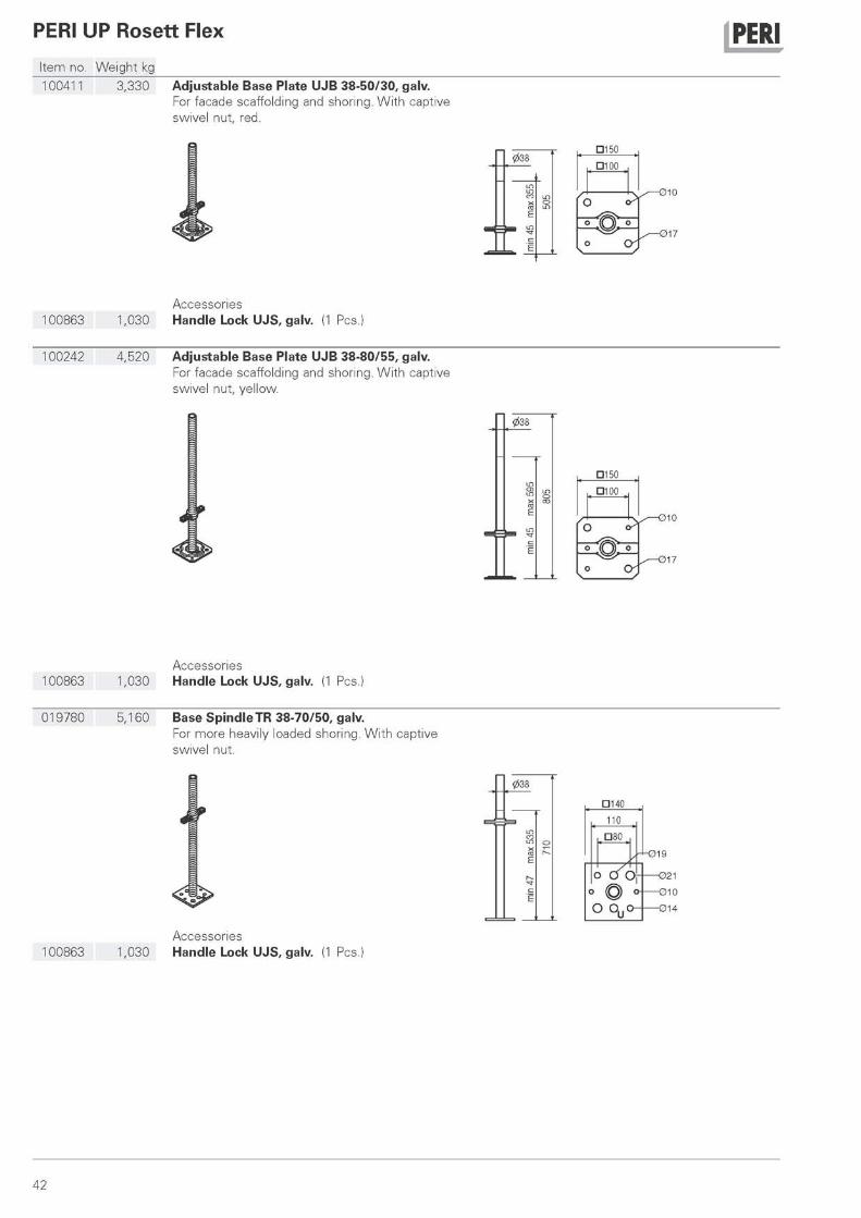
100242 4,520 Adjustable Base Plate UJB 38-80/55, galv. For facade scaffolding and shoring. With captive swivel nut, yellow.
100863 Accessories
1,030 Handle Lock UJS, galv. (1 Pcs.
019780 5,160 Base SpindleTR 38-70/50, galv. For more heavily loaded shoring. With captive swivel nut.
100863
Μ
Accessories 1,030 Handle Lock UJS, galv. (1 Pcs.
0
7
42
PERI UP Rosett Flex
Item no. Weight kg
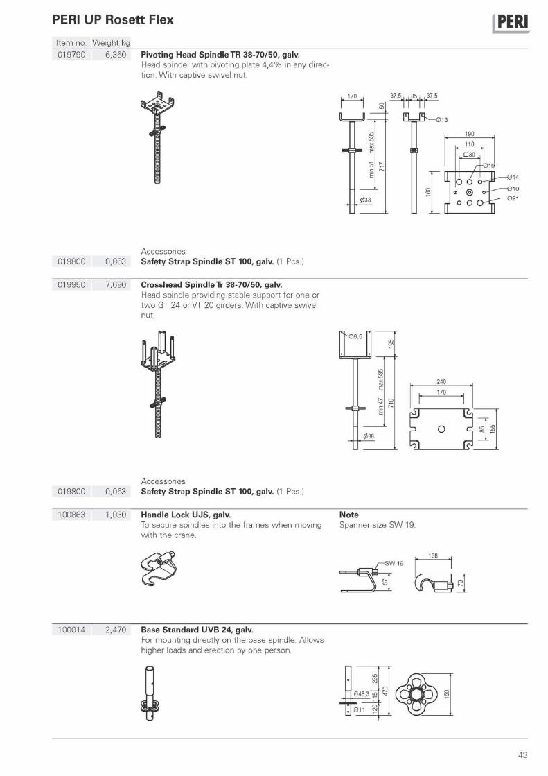
j PERI 019790 6,360 Pivoting Head Spindle TR 38-70/50, galv.
Head spindel with pivoting plate 4,4% in any direc-tion. With captive swivel nut.
170 3 7 , 5 . , 8 5 , , 3 7 , 5
0= S - — 0 1 3
019800 Accessories
0,063 Safety Strap Spindle ST 100, galv. (1 Pcs.)
019950 7,690 Crosshead Spindle Tr 38-70/50, galv. Head spindle providing stable support for one or two GT 24 or VT 20 girders. With captive swivel nut.
' 06 ,5
240
170
Ο
019800 Accessories
0,063 Safety Strap Spindle ST 100, galv. (1 Pcs.
100863 1,030 Handle Lock UJS, galv. To secure spindles into the frames when moving with the crane.
Note Spanner size SW 19.
SW 19 138
100014 2,470 Base Standard UVB 24, galv. For mounting directly on the base spindle. Allows higher loads and erection by one person.
43
PERI UP Rosett Flex j PERI i tem no. Weight kg
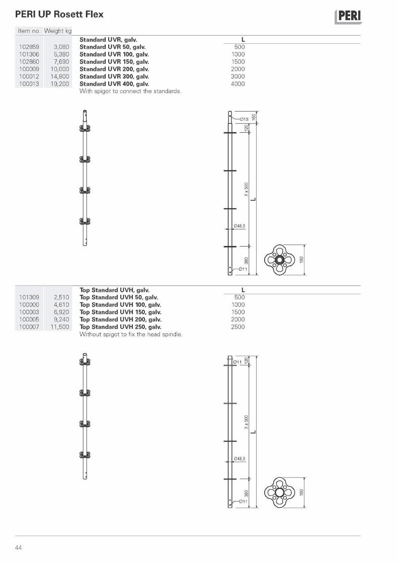
Standard UVR, galv. L 102859 3,080 Standard UVR 50, galv. 500 101306 5,380 Standard UVR 100, galv. 1000 102860 7,690 Standard UVR 150, galv. 1500 100009 10,000 Standard UVR 200, galv. 2000 100012 14,800 Standard UVR 300, galv. 3000 100013 19,200 Standard UVR 400, galv. 4000
With spigot to connect the standards.
^—013
048,3
/—011
Top Standard UVH, galv. 101309 2,510 Top Standard UVH 50, galv. 100000 4,610 Top Standard UVH 100, galv. 100003 6,920 Top Standard UVH 150, galv. 100005 9,240 Top Standard UVH 200, galv. 100007 11,500 Top Standard UVH 250, galv.
Without spigot to fix the head spindle.
L 500
1000 1500 2000 2500
44
PERI UP Rosett Flex
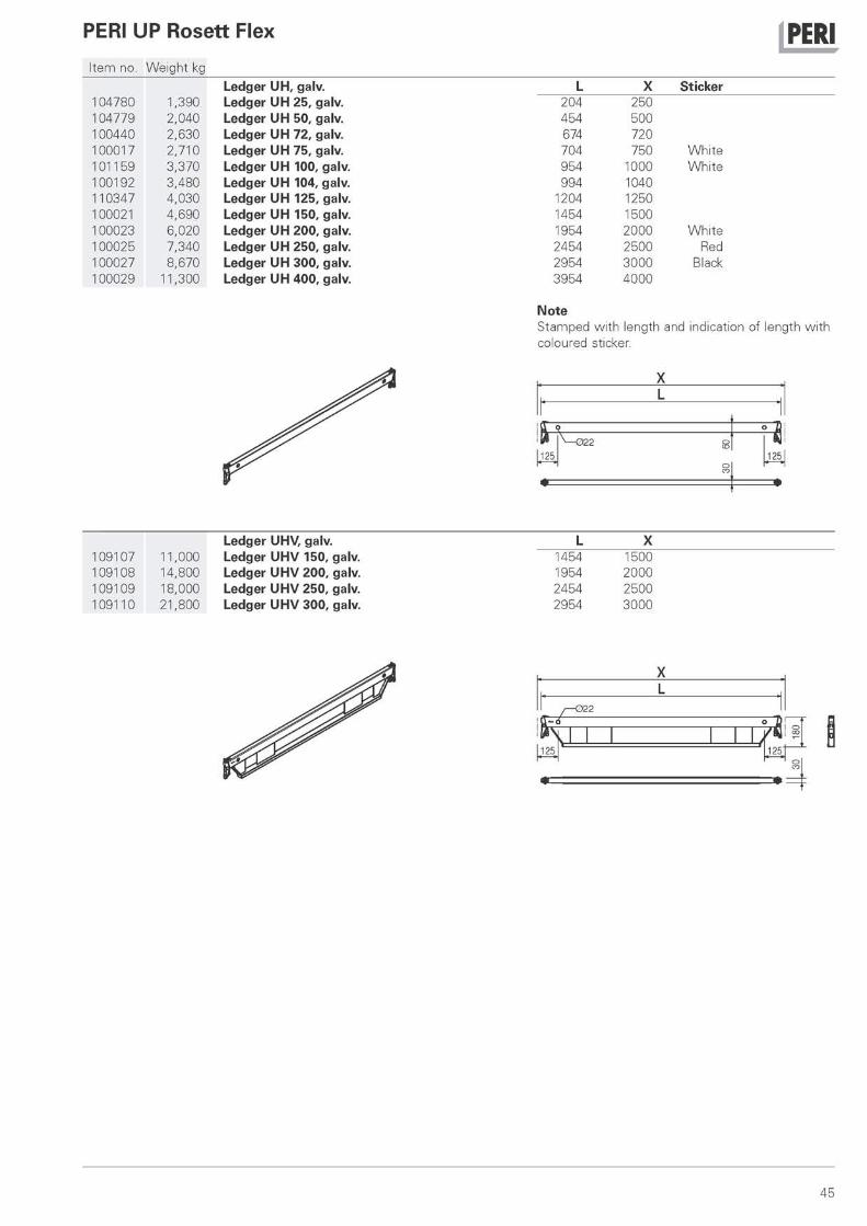
I tem no. Weight kg Ledger UH, galv.
104780 1,390 Ledger UH 25, galv. 104779 2,040 Ledger UH 50, galv. 100440 2,630 Ledger UH 72, galv. 100017 2,710 Ledger UH 75, galv. 101159 3,370 Ledger UH 100, galv. 100192 3,480 Ledger UH 104, galv. 110347 4,030 Ledger UH 125, galv. 100021 4,690 Ledger UH 150, galv. 100023 6,020 Ledger UH 200, galv. 100025 7,340 Ledger UH 250, galv. 100027 8,670 Ledger UH 300, galv. 100029 11,300 Ledger UH 400, galv.
j PERI L X Sticker
204 250 454 500 674 720 704 750 White 954 1000 White 994 1040
1204 1250 1454 1500 1954 2000 White 2454 2500 Red 2954 3000 Black 3954 4000
Note Stamped with length and indication of length with coloured sticker.
X
L 1454 1954 2454 2954
X 1500 2000 2500 3000
Ledger UHV, galv. 109107 11,000 Ledger UHV 150, galv. 109108 14,800 Ledger UHV 200, galv. 109109 18,000 Ledger UHV 250, galv. 109110 21,800 Ledger UHV 300, galv.
X L
- 0 2 2
125 \ f ^ I s 1251
45
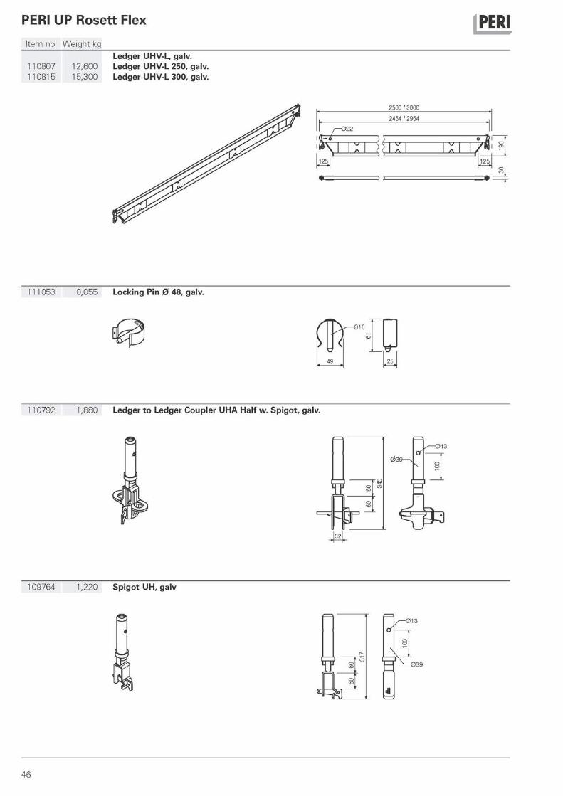
j PERI Ledger UHV-L, galv.
110807 12,600 Ledger UHV-L 250, galv. 110815 15,300 Ledger UHV-L 300, galv.
PERI UP Rosett Flex
Item no. Weight kg
iCFi •022
\
2500 / 3000
2454 / 2954
7. I CO
125
111053 0,055 Locking Pin 0 48, galv.
f — 0 1 0
49 25
110792 1,880 Ledger to Ledger Coupler UHA Half w. Spigot, galv.
109764 1,220 Spigot UH, galv
46
PERI UP Rosett Flex
Item no. Weight kg
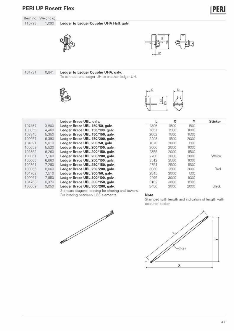
j PERI 110793 1,090 Ledger to Ledger Coupler UHA Half, galv.
Κ 32
101731 0,841 Ledger to Ledger Coupler UHA, galv. To connect one ledger UH to another ledger UH.
sn 83
A \ y
Ledger Brace UBL, galv. L X Y Sticker 107867 3,800 Ledger Brace UBL 150/50, galv. 1396 1500 500 100055 4,460 Ledger Brace UBL 150/100, galv. 1651 1500 1000 102846 5,350 Ledger Brace UBL 150/150, galv. 2002 1500 1500 100057 6,390 Ledger Brace UBL 150/200, galv. 2408 1500 2000 104391 5,010 Ledger Brace UBL 200/50, galv. 1 870 2000 500 100059 5,520 Ledger Brace UBL 200/100, galv. 2066 2000 1000 102862 6,260 Ledger Brace UBL 200/150, galv. 2355 2000 1500 100061 7,160 Ledger Brace UBL 200/200, galv. 2708 2000 2000 White 100063 6,660 Ledger Brace UBL 250/100, galv. 2512 2500 1000 102861 7,280 Ledger Brace UBL 250/150, galv. 2754 2500 1500 100065 8,060 Ledger Brace UBL 250/200, galv. 3060 2500 2000 Red 104762 7,510 Ledger Brace UBL 300/50, galv. 2845 3000 500 100067 7,850 Ledger Brace UBL 300/100, galv. 2976 3000 1000 104766 8,370 Ledger Brace UBL 300/150, galv. 31 82 3000 1500 100069 9,050 Ledger Brace UBL 300/200, galv. 3450 3000 2000 Black
Standard diagonal bracing for shoring and towers. For bracing between LGS elements. Note
Stamped with length and indication of length with coloured sticker.
47

PERI UP Rosett Flex j PERI Item no. Weight kg
Hor zontal Brace UBH Flex galv. L X Y 114896 8,210 Hor zontal Brace UBH Flex 250/75, galv. 2558 2500 750 114900 9,630 Hor zontal Brace UBH Flex 300/75, galv. 3042 3000 750 114818 4,670 Hor zontal Brace UBH Flex 100/100, galv. 1352 1000 1000 114821 5,820 Hor zontal Brace UBH Flex 150/100, galv. 1742 1500 1000 114819 8,440 Hor zontal Brace UBH Flex 250/100, galv. 2637 2500 1000 114892 9,820 Hor zontal Brace UBH Flex 300/100, galv. 3109 3000 1000 114904 5,710 Hor zontal Brace UBH Flex 125/125, galv. 1706 1250 1250 114908 6,250 Hor zontal Brace UBH Flex 150/125, galv. 1891 1500 1250 114912 6,750 Hor zontal Brace UBH Flex 150/150, galv. 2059 1500 1500 114916 8,820 Hor zontal Brace UBH Flex 200/200, galv. 2766 2000 2000 114920 9,920 Hor zontal Brace UBH Flex 250/200, galv. 3140 2500 2000 114924 11,100 Hor zontal Brace UBH Flex 300/200, galv. 3545 3000 2000 114928 10,900 Hor zontal Brace UBH Flex 250/250, galv. 3473 2500 2500 114932 12,000 Hor zontal Brace UBH Flex 300/250, galv. 3843 3000 2500 114936 13,000 Hor zontal Brace UBH Flex 300/300, galv. 4180 3000 3000
For horizontal bracing of towers.
Node Brace UBK, galv. L X Y Sticker 100969 6,760 Node Brace UBK 72/200, galv. 2179 720 2000 100977 4,850 Node Brace UBK 104/100, galv. 1472 1040 1000 100840 7,030 Node Brace UBK 104/200, galv. 2301 1040 2000 100981 5,710 Node Brace UBK 150/100, galv. 1821 1500 1000 100973 6,580 Node Brace UBK 150/150, galv. 2152 1500 1500 100572 7,600 Node Brace UBK 150/200, galv. 2539 1500 2000 100985 6,790 Node Brace UBK 200/100, galv. 2246 2000 1000 106630 7,510 Node Brace UBK 200/150, galv. 2521 2000 1500 100573 8,390 Node Brace UBK 200/200, galv. 2860 2000 2000 White 100989 7,940 Node Brace UBK 250/100, galv. 2696 2500 1000 106624 8,540 Node Brace UBK 250/150, galv. 2930 2500 1500 100574 9,310 Node Brace UBK 250/200, galv. 3226 2500 2000 Red 100993 9,130 Node Brace UBK 300/100, galv. 3131 3000 1000 100575 10,300 Node Brace UBK 300/200, galv. 3625 3000 2000 Black
For all applications using PERI UP Rosett, particu-larly on cantilevers.
48
PERI UP Rosett Flex j PERI Item no. Weight kg
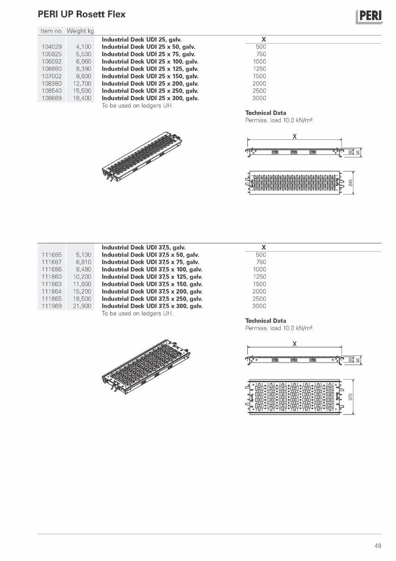
104029 4,100 Industrial Deck UDI 25, galv. Industrial Deck UDI 25 x 50, galv.
X 500
105925 5,530 Industrial Deck UDI 25 x 75, galv. 750 106092 6,960 Industrial Deck UDI 25 x 100, galv. 1000 106880 8,390 Industrial Deck UDI 25 x 125, galv. 1250 107002 9,800 Industrial Deck UDI 25 x 150, galv. 1500 108380 12,700 Industrial Deck UDI 25 x 200, galv. 2000 108540 15,500 Industrial Deck UDI 25 x 250, galv. 2500 108689 18,400 Industrial Deck UDI 25 x 300, galv. 3000
To be used on ledgers UH. Technical Data Permiss. load 10.0 kN/m2.
X
m ι » m °Q° τ s i s
111685 5,130 111687 6,810 111686 8,480 111860 10,200 111863 11,800 111864 15,200 111865 18,500 111969 21,900
Industrial Deck UDI 37,5, galv. Industrial Deck UDI 37,5 x 50, galv. Industrial Deck UDI 37,5 x 75, galv. Industrial Deck UDI 37,5 x 100, galv. Industrial Deck UDI 37,5 x 125, galv. Industrial Deck UDI 37,5 x 150, galv. Industrial Deck UDI 37,5 x 200, galv. Industrial Deck UDI 37,5 x 250, galv. Industrial Deck UDI 37,5 x 300, galv. To be used on ledgers UH.
X 500 750
1000 1250 1500 2000 2500 3000
Technical Data Permiss. load 10.0 kN/m2.
49

PERI UP Rosett Flex
Item no. Weight kg Toe Board Steel UPY, galv.
110213 0,927 Toe Board Steel UPY 50, galv. 110526 1 ,380 Toe Board Steel UPY 72, galv. 110514 1 ,440 Toe Board Steel UPY 75, galv. 110073 1 ,960 Toe Board Steel UPY 100, galv. 110076 2,040 Toe Board Steel UPY 104, galv. 110160 3,000 Toe Board Steel UPY 150, galv. 110176 4,030 Toe Board Steel UPY 200, galv. 110208 5,060 Toe Board Steel UPY 250, galv. 110211 6,100 Toe Board Steel UPY 300, galv.
j PERI L X
486 500 706 720 736 750 986 1000
1 01 6 1040 1486 1500 1986 2000 2486 2500 2986 3000
111011 0,797 Deck Link Plate UDC, galv. To connect two industrial decks.
1 1 U
180
^ L p c l J N T l s s B
119
Hatch UAF, galv. 109783 9,700 Hatch UAF 50 χ 75, galv. 109755 16,300 Hatch UAF 75 x 100, galv.
109879 3,820 Ladder UAF 200, galv.
ο m CO
213 6 x 280 = 1680
2170
50

PERI UP Rosett Flex j PERI Item no. Weight kg
Console Bracket UCM, galv. 110483 4,490 Console Bracket UCM 50-2, galv. 111128 5,720 Console Bracket UCM 75-2, galv.
112676 5,280 112678 6,510
Console Bracket UCM Console Bracket U C M Console Bracket UCM
with Spigot, galv. 50 wi th Spigot, galv. 75 wi th Spigot, galv.
Console Bracket UCM with half Rosett, galv. 112690 4,390 Console Bracket UCM 50 wi th half Rosett, galv. 112693 5,620 Console Bracket UCM 75 wi th half Rosett, galv.
51
PERI UP Rosett Flex
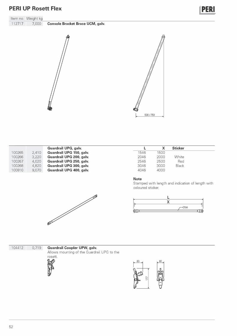
Item no. Weight kg 112717 7,000 Console Bracket Brace UCM, galv.
j PERI
Guardrail UPG, galv. L X Sticker 100265 2,410 Guardrail UPG 150, galv. 1546 1500 100266 3,220 Guardrail UPG 200, galv. 2046 2000 White 100267 4,020 Guardrail UPG 250, galv. 2546 2500 Red 100268 4,820 Guardrail UPG 300, galv. 3046 3000 Black 100810 9,070 Guardrail UPG 400, galv. 4046 4000
Note Stamped with length and indication of length with coloured sticker.
104412 0,719 Guardrail Coupler UPW, galv. Allows mounting of the Guardrail UPG to the rosett.
μ 60
52
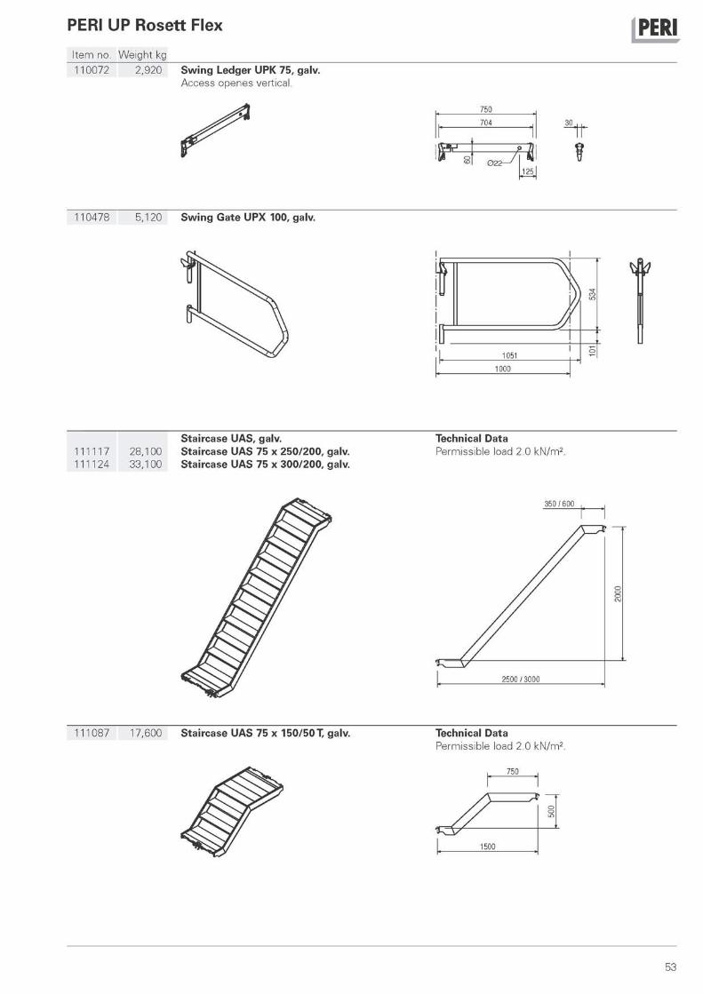
PERI UP Rosett Flex j PERI Item no. Weight kg 110072 2,920 Swing Ledger UPK 75, galv.
Access openes vertical.
750
704
3ΕΞ
125
30
110478 5,120 Swing Gate UPX 100, galv.
Staircase UAS, galv. 111117 28,100 Staircase UAS 75 χ 250/200, galv. 111124 33,100 Staircase UAS 75 x 300/200, galv.
Technical Data Permissible load 2.0 kN/m2.
350 / 600
111087 17,600 Staircase UAS 75 χ 150/50 Τ, galv. Technical Data Permissible load 2.0 kN/m2.
750
Λ A — / / ο m
1500
53
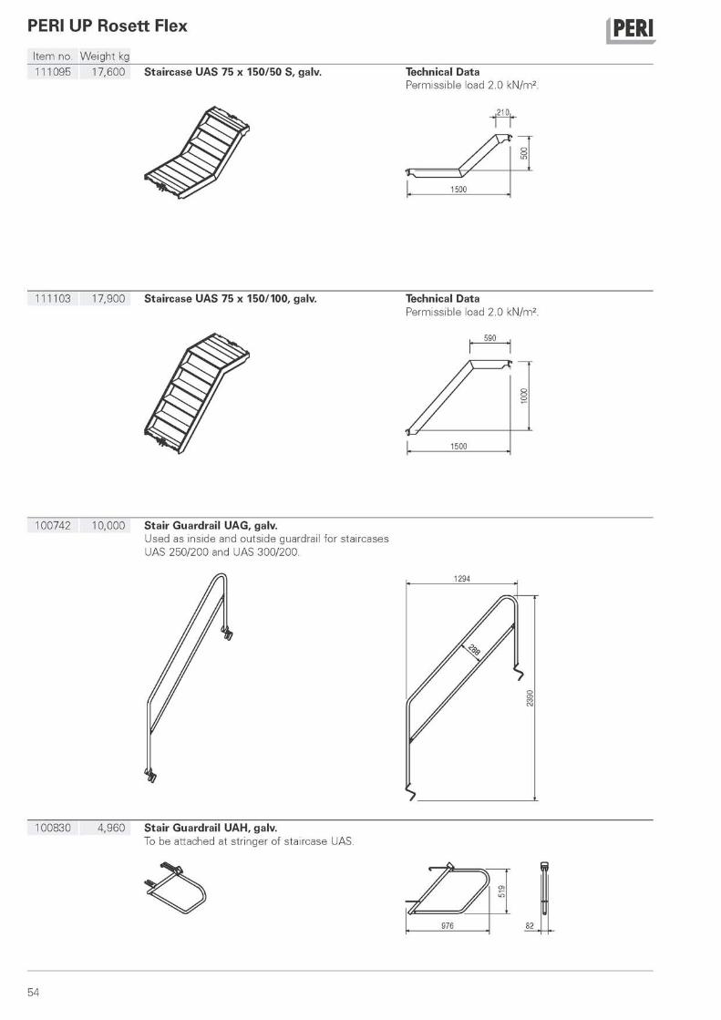
PERI UP Rosett Flex j PERI Item no. Weight kg 111095 17,600 Staircase UAS 75 χ 150/50 S, galv. Technical Data
Permissible load 2.0 kN/m2.
210,
100742 10,000 Stair Guardrail UAG, galv. Used as inside and outside guardrail for staircases UAS 250/200 and UAS 300/200.
100830 4,960 Stair Guardrail UAH, galv. To be attached at stringer of staircase UAS.
κ y cn £
976 82
54
PERI UP Rosett Flex j PERI Item no. Weight kg
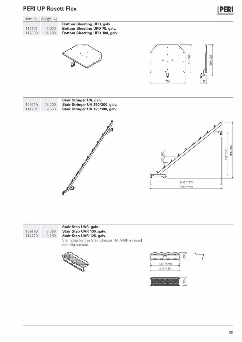
Bottom Sheeting UPD, galv. 111101 8,030 Bottom Sheeting UPD 75, galv. 112809 11,200 Bottom Sheeting UPD 100, galv.
ο ο
760
A 1-137.
Stair Stringer UA, galv. 109219 15,300 Stair Stringer UA 250/200, galv. 114731 9,350 Stair Stringer UA 125/100, galv.
Stair Step UAR, galv. 109198 7,390 Stair Step UAR 100, galv. 114179 9,250 Stair Step UAR 125, galv.
Stair step for the Stair Stringer UA. With a raised non-slip surface.
1 0 0 0 / 1 2 5 0
1 0 4 4 / 1 2 9 4
55
PERI UP Rosett Flex j PERI Item no. Weight kg
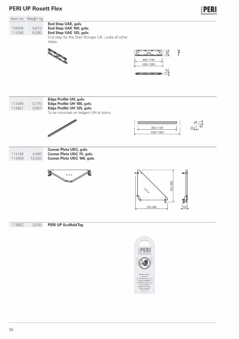
End Step UAE, galv. 109208 5,610 End Step UAE 100, galv. 114180 6,590 End Step UAE 125, galv.
End step for the Stair Stringer UA. Locks all other steps.
Edge Profile UH, galv. 114349 0,770 Edge Profile UH 100, galv. 114621 0,997 Edge Profile UH 125, galv.
To be mounted on ledgers UH at stairs.
850 / 1100
1000 / 1250
Corner Plate UDC, galv. 114148 4,890 Corner Plate UDC 75, galv. 113358 10,000 Corner Plate UDC 100, galv.
113832 0,035 PERI UP Scaffold Tag
107
56
PERI UP Rosett Flex j PERI Item no. Weight kg
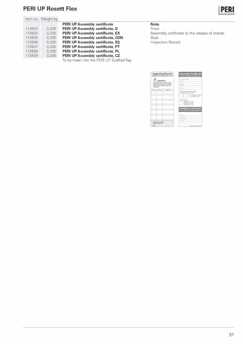
PERI UP Assembly certificate Note 113833 0,005 PERI UP Assembly certificate, D Front: 113834 0,005 PERI UP Assembly certificate, EX Assembly certificate to the release of stands. 113835 0,005 PERI UP Assembly certificate, CDN Back: 113836 0,005 PERI UP Assembly certificate, ES Inspection Record 113837 0,005 PERI UP Assembly certificate, PT 113838 0,005 PERI UP Assembly certificate, PL 113839 0,005 PERI UP Assembly certificate, CZ
To be insert into the PERI UP Scaffold Tag.
57

PERI International
PERI 01 PERI GmbH
Rudo l f -D iese l -S t rasse 8 9 2 6 4 W e i s s e n h o r n i n f o@per i . com w w w . p e r i . c o m
02 France 09 Italy 16 Austria 23 Korea 29 Slovania PERI S.A.S. PERI S.p.A. PERI G e s . m b H PERI (Korea) Ltd. PERI S l o w e n i e n 77109 M e a u x C e d e x 2 0 0 6 0 Bas iano 3134 NuBdorf ob der Traisen S e o u l 135-080 2 0 0 0 Mar i bo r per i .sas@per i . f r in fo@per i . i t o f f i ce@per i .a t i n fo@per i ko rea .com per i .s lo@tr ie ra .net w w w . p e r i . f r w w w . p e r i . i t w w w . p e r i . a t w w w . peri korea. c o m w w w . p e r i . c o m
03 Switzerland 10 Japan 17 Czech Republic 24 Portugal 30 Slovakia PERI AG PERI Japan K.K. PERI spol . s r.o. PERIco f ragens Lda PERI spol . s r.o. 8 4 7 2 O h r i n g e n Tokyo 103-0015 252 4 2 J e s e n i c e u Prahy 2 7 9 0 - 3 2 6 Que i jas 903 01 Senec in fo@per i .ch in fo@per i japan. jp in fo@per i .cz in fo@per i .p t in fo@per i .sk w w w . p e r i . c h w w w . p e r i j a p a n . j p w w w . p e r i . c z w w w . p e r i . p t w w w . p e r i . s k
04 Spain 11 United Kingdom/Ireland 18 Denmark 25 Argentina 31 Australia PERI S.A. PERI Ltd. PERI D a n m a r k A /S PERI S.A. PERI Aust ra l ia Pty. Ltd. 28110 A l g e t e - M a d r i d Rugby, CV23 0 A N 2 6 7 0 Greve B1625GPA Escobar - Bs. As. G l e n d e n n i n g N S W 2761 in fo@per i .es in fo@per i . l td .uk per i@per i .dk in fo@per i . com.ar i n fo@per iaus .com.au w w w . p e r i . e s w w w . p e r i . l t d . u k w w w . p e r i . d k w w w . p e r i . c o m . a r w w w . p e r i a u s . c o m . a u
05 Belgium/Luxembourg 12 Turkey 19 Finland 26 Brazil 32 Estonia N.V. PERI S.A. PERI Kalip v e iske le ler i PERI S u o m i Ltd. Oy PERI Formas e PERI AS 1840 Londerzee l Esenyur t / i s tanbu l 34510 0 5 4 6 0 Hyv inkaa E s c o r a m e n t o s Ltda. 76406 Saku va ld in fo@per i .be in fo@per i . com. t r i n fo@per i suomi . f i V a r g e m Grande Paul ista Har jumaa w w w . p e r i . b e w w w . p e r i . c o m . t r w w w . p e r i s u o m i . f i Sao Paulo per i@per i .ee
in fo@per ib ras i l . com.b r w w w . p e r i . e e 06 Netherlands 13 Hungary 20 Norway w w w . p e r i b r a s i l . c o m . b r
PERI B.V. PERI Kft.. PERI No rge AS 33 Greece 5 4 8 0 AH-Sch i jnde l 1181 Budapes t 3 0 3 6 D r a m m e n 27 Chile PERI Hel las Ltd. in fo@per i .n l in fo@per i .hu in fo@per i .no PERI Chi le Ltda. 194 0 0 Koropi w w w . p e r i . n l w w w . p e r i . h u w w w . p e r i . n o Col ina, Sant iago d e Chi le in fo@per ihe l las .gr
per i .ch i le@per i .c l w w w . p e r i h e l l a s . g r 07 USA 14 Malaysia 21 Poland w w w . p e r i . c l
PERI F o r m w o r k Sys tems , Inc. PERI F o r m w o r k Malaysia PERI Polska Sp. z o.o. 34 Latvia Elkr idge, M D 21075 Sdn. Bhd. 0 5 - 8 6 0 Ptochocin 28 Romania PERI SIA in fo@per i -usa .com 4 3 3 0 0 Ser i K e m b a n g a n , in fo@per i .p l .p l PERI Romania SRL 2118 Salaspi ls novads , w w w . p e r i - u s a . c o m Selangor Daru l Ehsan w w w . p e r i . p l . p l 077015 B a l o t e j t i Rigas ra jons
i n fo@per ima lays ia . com in fo@per i . ro in fo@per i - la tv i ja . lv 08 Indonesia w w w . p e r i m a l a y s i a . c o m 22 Sweden w w w . p e r i . r o w w w . p e r i - l a t v i j a . l v
PT Be ton Perkasa W i j aksana PERI fo rm Sver ige A B Jakar ta 10210 15 Singapore 30013 H a l m s t a d 35 United Arab Emirates b p w @ b e t o n p e r k a s a . c o m PERI AS IA Pte. L td pe r i@per i f o rm .se PERI (L.L.C.) w w w . p e r i . c o m S ingapore 3 8 7 3 5 5 w w w . p e r i f o r m . s e Dubai
pha@per ias ia .com p e r i l l c @ p e r i m e . c o m w w w . p e r i a s i a . c o m w w w . p e r i m e . c o m
58
-
64
45
41
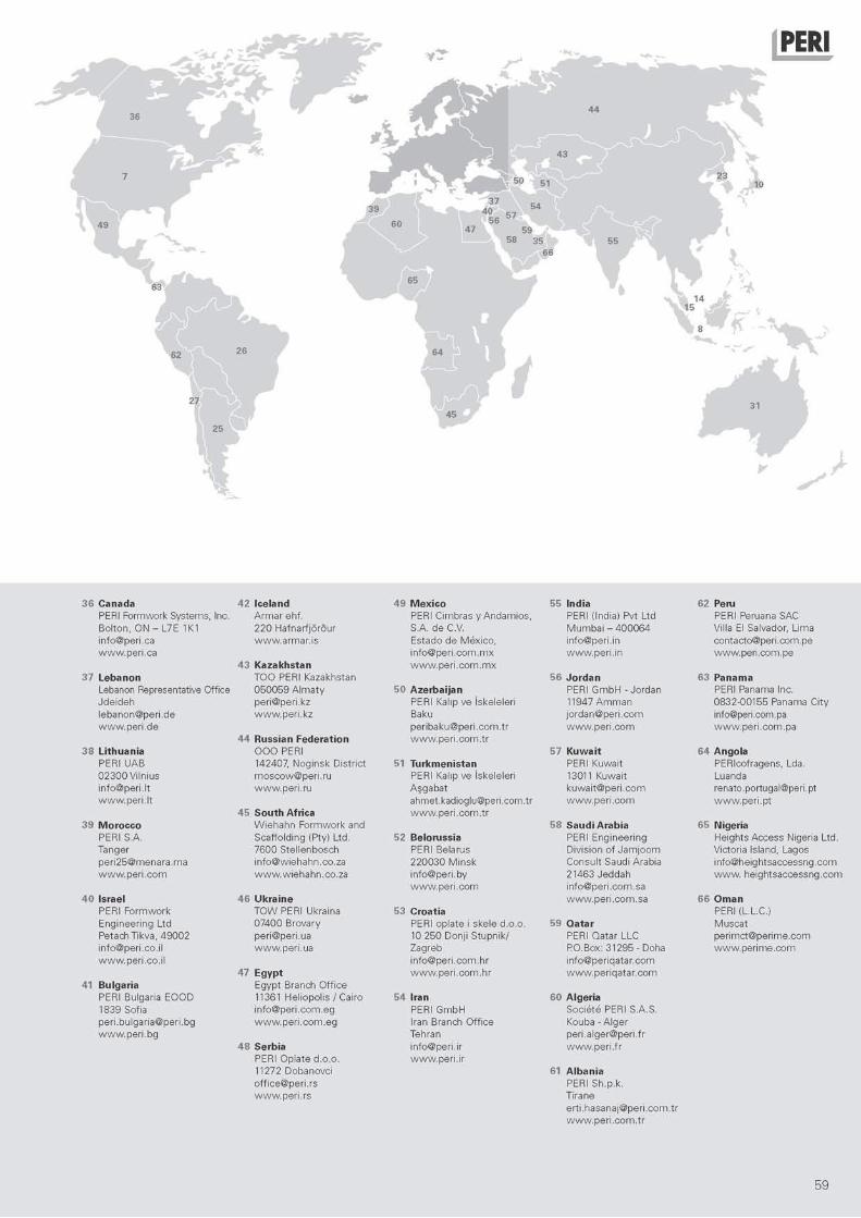
Canada 42 Iceland 49 Mexico 55 India 62 Peru PERI Fo rmwork Sys tems, Inc. A r m a r ehf . PERI C imbras y A n d a m i o s , PERI (India) Pvt L td PERI Peruana SAC Bo l ton , O N - L7E 1K1 2 2 0 Ha fna r f j o r3u r S.A. d e C.V. M u m b a i - 4 0 0 0 6 4 Villa El Salvador, L ima in fo@per i .ca w w w . a r m a r . i s Es tado d e M e x i c o , in fo@per i . in contac to@per i .com.pe w w w . p e r i . c a
43 Kazakhstan i n f o @ p e r i . c o m . m x w w w . p e r i . c o m . m x
w w w . p e r i . i n w w w . p e r i . c o m . p e
Lebanon T O O PERI Kazakhstan 56 Jordan 63 Panama Lebanon Representative Off ice 0 5 0 0 5 9 A l m a t y 50 Azerbaijan PERI G m b H - Jo rdan PERI Panama Inc. J d e i d e h per i@per i .kz PERI Kalip ve iskele ler i 11947 A m m a n 0832 -00155 Panama Ci ty l ebanon@per i .de w w w . p e r i . k z Baku j o rdan@per i . com [email protected] w w w . p e r i . d e
44 Russian Federation per ibaku@per i . com. t r w w w . p e r i . c o m . t r
w w w . p e r i . c o m w w w . p e r i . c o m . p a
Lithuania O O O PERI 57 Kuwait 64 Angola PERI UAB 142407, Nog insk Dis t r ic t 51 Turkmenistan PERI Kuwai t PERIcof ragens, Lda. 0 2 3 0 0 Vi ln ius m o s c o w @ p e r i . r u PERI Kalip ve iskele ler i 13011 Kuwai t Luanda in fo@per i . l t w w w . p e r i . r u A j g a b a t k u w a i t @ p e r i . c o m renato.portugal@peri .pt w w w . p e r i . l t
45 South Africa ahmet.kadioglu@per i .com.tr w w w . p e r i . c o m . t r
w w w . p e r i . c o m w w w . p e r i . p t
Morocco W i e h a h n F o r m w o r k and 58 Saudi Arabia 5 Nigeria PERI S.A. Sca f fo ld ing (Pty) Ltd. 52 Belorussia PERI Eng inee r ing He igh ts Access Nigeria Ltd. Tanger 7 6 0 0 S te l l enbosch PERI Belarus D iv is ion of J a m j o o m Victor ia Island, Lagos p e r i 2 5 @ m e n a r a . m a in fo@wiehahn .co .za 2 2 0 0 3 0 M i n s k Consu l t Saudi Arabia i n fo@he igh tsaccessng .com w w w . p e r i . c o m w w w . w i e h a h n . c o . z a in fo@per i .by
w w w . p e r i . c o m 21463 J e d d a h in fo@per i . com.sa
w w w . he igh t saccessng . com
Israel 46 Ukraine w w w . p e r i . c o m . s a 66 Oman PERI F o r m w o r k T O W PERI Ukraina 53 Croatia PERI (L.L.C.) Eng inee r ing L td 07400 Brovary PERI op la te i ske le d .o .o . 59 Qatar M u s c a t Petach Tikva, 4 9 0 0 2 per i@per i .ua 10 250 Donj i S tupn i k / PERI Qatar LLC p e r i m c t @ p e r i m e . c o m in fo@per i .co. i l w w w . p e r i . u a Zagreb PO.Box: 31295 - Doha w w w . p e r i m e . c o m w w w . p e r i . c o . i l i n fo@per i . com.h r i n fo@per iqa ta r . com
47 Egypt w w w . p e r i . c o m . h r w w w . p e r i q a t a r . c o m Bulgaria Egypt Branch O f f i c e PERI Bulgar ia E O O D 11361 He l iopo l i s / Cairo 54 Iran 60 Algeria 1839 Sofia i n fo@per i . com.eg PERI G m b H Soc ie te PERI S.A.S. per i .bu lgar ia@per i .bg w w w . p e r i . c o m . e g Iran Branch O f f i ce Kouba - A l g e r w w w . p e r i . b g Tehran per i .a lger@per i . f r
48 Serbia in fo@peri . i r w w w . p e r i . f r PERI Op la te d .o .o . w w w . p e r i . i r 11272 Dobanovc i 61 Albania of f i ce@per i . r s PERI Sh.p.k . w w w . p e r i . r s T i rane
e r t i . hasana j@per i . com. t r w w w . p e r i . c o m . t r
59

The optimal System for every Pro-ject and every Requirements
Slab Formwork Climbing Systems Tunnel Formwork Bridge Formwork
Shoring Systems
r . t M r
Construction Scaffold Facade Scaffold Industrial Scaffold
Access Protection Scaffold System-Independent Accessories Services
PERI PERI GmbH Formwork Scaffolding Engineering PO. Box 1264 8 9 2 5 9 W e i s s e n h o r n Ge rmany Tel. + 4 9 (0)7309.950-0 Fax + 4 9 (0)7309.951-0 in fo@per i . com w w w . p e r i . c o m
Related Documents