PMX-2ED-SA Manual page 1 Rev 1.14 Performax 2ED-SA 2-Axis Stepper Motor Controller/Driver Standalone Version Manual

Welcome message from author
This document is posted to help you gain knowledge. Please leave a comment to let me know what you think about it! Share it to your friends and learn new things together.
Transcript

PMX-2ED-SA Manual page 1 Rev 1.14
Performax 2ED-SA
2-Axis
Stepper Motor Controller/Driver
Standalone Version
Manual

PMX-2ED-SA Manual page 2 Rev 1.14
COPYRIGHT © 2006 ARCUS,
ALL RIGHTS RESERVED
First edition, January 2006
ARCUS TECHNOLOGY copyrights this document. You may not reproduce or translate
into any language in any form and means any part of this publication without the written
permission from ARCUS.
ARCUS makes no representations or warranties regarding the content of this document.
We reserve the right to revise this document any time without notice and obligation.
Revision History:
1.00 – 1st Revision
1.13 – 2nd
Revision
1.14 – 3rd
Revision
Firmware Compatibility: †V123BL
†If your module’s firmware version number is less than the listed value, contact Arcus for the appropriate
documentation.

PMX-2ED-SA Manual page 3 Rev 1.14
Table of Contents
1. Introduction __________________________________________________________ 6
Features _____________________________________________________________ 6
2. Electrical Specifications ________________________________________________ 7
Power Requirement ____________________________________________________ 7
Temperature Ratings † _________________________________________________ 7
Pulse, Dir, Enable Outputs ______________________________________________ 7
Digital Inputs ________________________________________________________ 7
Digital Outputs _______________________________________________________ 7
3. Dimensions __________________________________________________________ 8
4. Pin Descriptions ______________________________________________________ 9
2-Pin Connector (5.08mm) – Controller Power ______________________________ 9
4-Pin Connectors (2.54mm) _____________________________________________ 9
2-Pin Connector (2.54mm) – Driver Power ________________________________ 10
50-Pin Control/Encoder IO _____________________________________________ 10
Interface Circuit _____________________________________________________ 12
Digital Outputs ______________________________________________________ 13
Digital Inputs _______________________________________________________ 13
Encoder Inputs ______________________________________________________ 14
Analog Inputs _______________________________________________________ 14
Driver Current and Microstep Setting _____________________________________ 14
5. Getting Started ______________________________________________________ 16
Typical Setup _______________________________________________________ 16
Main Control Screen __________________________________________________ 17
6. Motion Control Feature Overview _______________________________________ 27
Motion Profile _______________________________________________________ 27
Pulse Speed _________________________________________________________ 28
On-The-Fly Speed Change _____________________________________________ 28
Motor Status ________________________________________________________ 29
Individual/Linear Interpolation Moves ____________________________________ 29
On-The-Fly Target Position Change ______________________________________ 30
Homing ____________________________________________________________ 30
Home Input Only (High speed only) ___________________________________ 30
Home Input Only (High speed and low speed) ____________________________ 31
Limit Only ________________________________________________________ 32
Home and Z-index _________________________________________________ 32
Z-index only ______________________________________________________ 33
Jogging ____________________________________________________________ 33
Stopping Motor ______________________________________________________ 33
Motor Position ______________________________________________________ 33
Polarity ____________________________________________________________ 34
Limits _____________________________________________________________ 34
Digital Inputs/Outputs and Enable Outputs ________________________________ 34
Analog Inputs _______________________________________________________ 36
Joystick Control _____________________________________________________ 36

PMX-2ED-SA Manual page 4 Rev 1.14
StepNLoop Closed Loop Control ________________________________________ 37
Device Number ______________________________________________________ 40
Standalone Program Specification _______________________________________ 40
Storing to Flash ______________________________________________________ 41
7. Communication ______________________________________________________ 42
USB Communication API Functions _____________________________________ 42
USB Communication Issues ____________________________________________ 43
8. ASCII Language Specification __________________________________________ 44
Error Codes _________________________________________________________ 48
9. Standalone Language Specification ______________________________________ 49
; __________________________________________________________________ 49
ABORT ____________________________________________________________ 49
ABORT[axis] _______________________________________________________ 49
ABS _______________________________________________________________ 49
ACC ______________________________________________________________ 50
ACC[axis] __________________________________________________________ 50
AI[1-2] ____________________________________________________________ 51
DEC_______________________________________________________________ 51
DEC[axis] __________________________________________________________ 51
DELAY ____________________________________________________________ 52
DI ________________________________________________________________ 52
DI[1-8] ____________________________________________________________ 52
DO ________________________________________________________________ 53
DO[1-8] ____________________________________________________________ 53
E[axis] _____________________________________________________________ 53
ECLEAR[axis] ______________________________________________________ 54
ELSE ______________________________________________________________ 54
ELSEIF ____________________________________________________________ 54
END ______________________________________________________________ 55
ENDIF _____________________________________________________________ 55
ENDSUB___________________________________________________________ 56
ENDWHILE ________________________________________________________ 56
EO ________________________________________________________________ 56
EO[1-2] ____________________________________________________________ 57
GOSUB ____________________________________________________________ 57
HLHOME[axis][+ or -] ________________________________________________ 58
HOME[axis][+ or -] __________________________________________________ 58
HSPD _____________________________________________________________ 58
HSPD[axis] _________________________________________________________ 58
IF _________________________________________________________________ 59
INC _______________________________________________________________ 59
JOG[axis] __________________________________________________________ 60
JOYENA ___________________________________________________________ 60
JOYHS[axis] ________________________________________________________ 60
JOYDEL[axis] ______________________________________________________ 60
JOYNO[axis] _______________________________________________________ 61

PMX-2ED-SA Manual page 5 Rev 1.14
JOYNI[axis] ________________________________________________________ 61
JOYPI[axis]_________________________________________________________ 61
JOYPO[axis] ________________________________________________________ 61
JOYTOL[axis] ______________________________________________________ 62
LHOME[axis][+ or -] _________________________________________________ 62
LSPD ______________________________________________________________ 62
LSPD[axis] _________________________________________________________ 62
MST[axis] __________________________________________________________ 63
P[axis] _____________________________________________________________ 63
PRG _______________________________________________________________ 63
PS[axis] ____________________________________________________________ 64
SCV[axis] __________________________________________________________ 64
SL[axis] ____________________________________________________________ 65
SLS[axis]___________________________________________________________ 65
SR[0,1] ____________________________________________________________ 65
SSPD[axis] _________________________________________________________ 65
SSPDM[axis] _______________________________________________________ 66
STOP ______________________________________________________________ 66
STOP[axis] _________________________________________________________ 66
STORE ____________________________________________________________ 67
SUB _______________________________________________________________ 67
TOC_______________________________________________________________ 67
V _________________________________________________________________ 67
WAIT _____________________________________________________________ 68
WHILE ____________________________________________________________ 68
X _________________________________________________________________ 69
Y _________________________________________________________________ 69
ZHOME[axis][+ or -] _________________________________________________ 70
ZOME[axis][+ or -] __________________________________________________ 70
10. Example Standalone Programs _________________________________________ 71
Standalone Example Program 1 – Single Thread ____________________________ 71
Standalone Example Program 2 – Single Thread ____________________________ 71
Standalone Example Program 3 – Single Thread ____________________________ 71
Standalone Example Program 4 – Single Thread ____________________________ 72
Standalone Example Program 5 – Single Thread ____________________________ 72
Standalone Example Program 6 – Single Thread ____________________________ 73
Standalone Example Program 7 – Multi Thread_____________________________ 74
Standalone Example Program 8 – Multi Thread_____________________________ 75
Appendix A: Speed Settings ______________________________________________ 76
Acceleration/Deceleration Range ________________________________________ 76
Acceleration/Deceleration Range – Positional Move _________________________ 77

PMX-2ED-SA Manual page 6 Rev 1.14
1. Introduction
PMX-2ED-SA is an advanced 2 axis stepper standalone programmable motion controller.
Communication to the PMX-2ED-SA can be established over USB. It is also possible to
download a standalone program to the device and have it run independent of a host.
Features
PMX-2ED-SA
- USB 2.0 communication
- Standalone programmable
- Maximum pulse output rate of 400K PPS
- Trapezoidal or s-curve acceleration
- On-the-fly speed change
- XY linear coordinated motion
- A/B/Z differential encoder inputs [Max frequency of 5 MHz]
• StepNLoop closed loop control (position verification)
- Pulse/Dir/Enable open collector outputs per axis
- Opto-isolated I/O
• 8 x inputs
• 8 x outputs
• +Limit/-Limit/Home inputs per axis
- Homing routines:
• Home input only (high speed)
• Home input only (high speed + low speed)
• Limit only
• Z-index encoder channel only
• Home input + Z index encoder channel
- 2 x 10-bit analog inputs
• Joystick control
- Stepper driver
• 12-24 VDC
• 1.5 Amp max current setting (peak current)
• Full step, 2, 4, or 8 micro-step setting
• Max pulse input rate of 400K
Contacting Support
For technical support contact: [email protected].
Or, contact your local distributor for technical support.

PMX-2ED-SA Manual page 7 Rev 1.14
2. Electrical Specifications
Power Requirement
Regulated Voltage: +12 to +24 VDC
Current (Max): 1.5A (Peak)
Temperature Ratings †
Operating Temperature: -20°C to +80°C
Storage Temperature: -55°C to +150°C
† Based on component ratings
Pulse, Dir, Enable Outputs
Type: Open-collector output
Max sink voltage: +24 VDC
Max sink current: 40 mA
Digital Inputs
Type: Opto-isolated inputs (NPN)
Voltage range: +12V to +24VDC
Max foward current: 40 mA
Digital Outputs
Type: Opto-isolated outputs (NPN)
Max voltage: +12V to +24VDC
Max source current: 90 mA

PMX-2ED-SA Manual page 8 Rev 1.14
3. Dimensions
Figure 3.0

PMX-2ED-SA Manual page 9 Rev 1.14
4. Pin Descriptions
In order for PMX-2ED-SA to operate, it must be supplied with +12VDC to +24VDC.
Power pins as well as communication port pin outs are shown below.
Figure 4.0
2-Pin Connector (5.08mm) – Controller Power
Pin # In/Out Name Description
1 I G Ground
2 I V+ Power Input +12 to +24 VDC
Table 4.0
Mating Connector Description: 2 pin 0.2” (5.08mm) connector
Mating Connector Manufacturer: On-Shore
Mating Connector Manufacturer Part: †EDZ950/2
† Other 5.08mm compatible connectors can be used.
Figure 4.1
4-Pin Connectors (2.54mm)
Pin # In/Out Name Description
1 O AX Bi-polar Step Motor – X-axis Phase A
2 O /AX Bi-polar Step Motor – X-axis Phase /A
3 O BX Bi-polar Step Motor – X-axis Phase B
4 O /BX Bi-polar Step Motor – X-axis Phase /B
Table 4.1
Pin # In/Out Name Description
1 O AY Bi-polar Step Motor – Y-axis Phase A
2 O /AY Bi-polar Step Motor – Y-axis Phase /A
3 O BY Bi-polar Step Motor – Y-axis Phase B

PMX-2ED-SA Manual page 10 Rev 1.14
4 O /BY Bi-polar Step Motor – Y-axis Phase /B
Table 4.2
Mating Connector Description: 4 pin 0.1" (2.54mm) connector
Mating Connector Manufacturer: AMP/Tyco
Mating Connector Manufacturer Part: 770602-4
2-Pin Connector (2.54mm) – Driver Power
The stepper driver power is separate from the controller power. Voltage range is also 12-
24VDC.
Pin # In/Out Name Description
1 I G Ground
2 I V+ Power Input +12 to +24 VDC
Table 4.3
Mating Connector Description: 2 pin 0.2” (5.08mm) connector
Mating Connector Manufacturer: On-Shore
Mating Connector Manufacturer Part: †EDZ950/2
50-Pin Control/Encoder IO
Pin # In/Out Name Description
1 O +5V +5V
2 O G Ground
3 I AX A Channel Encoder Input [X-Axis]
4 I /AX /A Channel Encoder Input [X-Axis]
5 I BX B Channel Encoder Input [X-Axis]
6 I /BX /B Channel Encoder Input [X-Axis]
7 I ZX Z Index Encoder Input [X-Axis]
8 I /ZX /Z Index Encoder Input [X-Axis]
9 I AY A Channel Encoder Input [Y-Axis]
10 I /AY /A Channel Encoder Input [Y-Axis]
11 I BY B Channel Encoder Input [Y-Axis]
12 I /BY /B Channel Encoder Input [Y-Axis]
13 I ZY Z Index Encoder Input [Y-Axis]
14 I /ZY /Z Index Encoder Input [Y-Axis]
15 I AI1 Analog Input 1
16 I AI2 Analog Input 2
17 I +LX +Limit [X-Axis]

PMX-2ED-SA Manual page 11 Rev 1.14
18 I -LX -Limit [X-Axis]
19 I HX Home [X-Axis]
20 NC NC No Connection
21 I +LY +Limit [Y-Axis]
22 I -LY -Limit [Y-Axis]
23 I HY Home [Y-Axis]
24 NC NC No Connection
25 NC NC No Connection
26 NC NC No Connection
27 NC NC No Connection
28 NC NC No Connection
29 NC NC No Connection
30 NC NC No Connection
31 I Opto-
Supply
Opto-Supply Input +12 to +24VDC
32 I Opto-
Ground
Opto-Ground
33 I DI1 Digital Input 1
34 I DI2 Digital Input 2
35 I DI3 Digital Input 3
36 I DI4 Digital Input 4
37 I DI5 Digital Input 5
38 I DI6 Digital Input 6
39 I DI7 Digital Input 7
40 I DI8 Digital Input 8
41 O DO1 Digital Output 1
42 O DO2 Digital Output 2
43 O DO3 Digital Output 3
44 O DO4 Digital Output 4
45 O DO5 Digital Output 5
46 O DO6 Digital Output 6
47 O DO7 Digital Output 7
48 O DO8 Digital Output 8
49 NC NC No Connection
50 NC NC No Connection
Table 4.4
Mating Connector Description: 50 pin 0.1" connector
Mating Connector Manufacturer: CW Industries
Mating Connector Manufacturer Part: C3AAG-5018M
† Other compatible connectors can be used.
PMX-2ED-SA Manual page 12 Rev 1.14
Interface Circuit
Figure 4.2

PMX-2ED-SA Manual page 13 Rev 1.14
Digital Outputs
Digital outputs are opto-isolated outputs using Darlington transistors that can sink up to
100mA current at maximum voltage of 24VDC.
Figure 4.3
Digital Inputs
All inputs including limits, homes, and digital inputs DI1 to DI8 are opto-isolated and
require a opto-supply input of 12 to 24VDC.
To trigger the input, sink the signal to the ground of the opto-supply.
Figure 4.4

PMX-2ED-SA Manual page 14 Rev 1.14
Encoder Inputs
When connecting differential connector use Encoder A, /A, B, /B, Z index, /Z index
channels.
When connecting single-ended encoders, use Encoder /A, /B, and /Z index channels.
Analog Inputs
Analog inputs are 0 to 5V range and 10 bit in resolution. Using two analog inputs,
joystick control can be achieved.
The maximum source current for the analog inputs is 10mA.
Driver Current and Microstep Setting
PMX-2ED-SA has two built-in bipolar microstep drivers.
Figure 4.5
To set the current, open up the top cover. There are two dual row jumper headers JP1
(for X axis) and JP2 (for Y axis).
There are four preset current settings: 1.2A, 1.0A, 0.7A, and 0.5A. Any of these current
setting can be selected using a jumper.
For custom current setting, use the following formula to get the resistor value and solder
across the custom current setting pins.
Resistor Value = [4167 / Current (A)] + 1000
For example, to set the current to 0.3A, resistor value will be 14.9K Ohm.

PMX-2ED-SA Manual page 15 Rev 1.14
To set the microstep, use the SW1 (for X axis) and SW2 (for Y axis) headers.
MS1 MS2
1/8th
microstep Open Open
¼ microstep Open Close
½ microstep Close Open
Full step Close Close
Table 4.5

PMX-2ED-SA Manual page 16 Rev 1.14
5. Getting Started
Typical Setup
PC-Controlled
Figure 5.0
Stand-Alone Operation
Figure 5.1

PMX-2ED-SA Manual page 17 Rev 1.14
Main Control Screen
Figure 5.2
B
A
F G
H
I
E
J
D
C K
L
M
N

PMX-2ED-SA Manual page 18 Rev 1.14
A. Status
Figure 5.3
1. Current pulse position (X/Y axis).
2. Current encoder position (X/Y axis).
3. Current speed (X/Y axis).
4. Motor status (X/Y axis).
i. IDLE - Motor is not moving.
ii. ACCEL - Motor is accelerating.
iii. CONST - Motor is moving at constant speed
iv. DECEL - Motor is decelerating.
5. StepNLoop status.
i. NA – StepNLoop is disabled.
ii. IDLE – Motor is not moving.
iii. MOVING – Motor is moving.
iv. CORRECTING – Motor is attempting to correct its
position.
v. STOPPING – Motor is stopping using deceleration.
vi. ABORTING – Motor is stopping without deceleration.
vii. JOGGING – Motor is jogging.
viii. HOMING – Motor is homing using the home switch.
ix. L-HOMING -Motor is homing using the limit switch.
x. Z-HOMING – Motor is homing using the Z-index
xi. ERR-RANGE – The error range has been exceeded.
xii. ERR-ATTMPT – The maximum number of attempts has
been made to correct the position.
xiii. ERR-STALL – The motor has stalled.
xiv. ERR-LIM – A limit switch has been hit.
6. StepNLoop delta status (X/Y axis).
7. –Limit, +Limit, Home input status (X/Y axis).
8. Z encoder index channel status (X/Y axis).
9. Clear motor status and StepNLoop status button for both axes.
10. Move mode.
i. ABS mode: On individual and interpolated move
commands, motor will move to target position.
1 2 3 4 5 6 7 8
10 9

PMX-2ED-SA Manual page 19 Rev 1.14
ii. INC mode: On individual and interpolated move
commands, motor will increase its position by the target
position amount.
B. Control
Figure 5.4
1. Global high speed, low speed, and acceleration values are entered
here (X/Y axis). To give each axis individual speed parameters,
enter HSPD[axis], LSPD[axis], and ACC[axis] into the command
line in the “Terminal” section.
2. Select X/Y axis. Selection of both the axes will result in
synchronous movement.
3. Target position entered here (X/Y axis).
4. Enables the driver power for the indicated motor (X/Y axis).
5. H+/H- – Home the motor at high speed using only the home
sensor.
6. RSTOP/ISTOP – Stop the motor with deceleration using RSTOP.
Stop the motor immediately using ISTOP.
7. RP/RE – Reset the position/encoder position.
8. ABS/INC – Set the move mode to absolute or incremental.
9. J+/J- – Jogs the motor in the positive or negative direction.
10. HL+/HL- – Home the motor at high speed and low speed using
only the home sensor.
11. Z+/Z- – Only encoder index channel used for homing.
12. L+/L- – Home the motor using only the limit sensor.
13. ZH+/ZH- – Both encoder index and home sensor used for homing.
14. DAT/ABS – Move the motor to position zero by using DAT.
Move the motor to the target position by using ABS.
1
13
14
2 3
10
7
9 11 12 8
4
5
6

PMX-2ED-SA Manual page 20 Rev 1.14
C. On-The-Fly Speed
Figure 5.5
1. Select X/Y axis.
2. Select destination speed of the axis.
3. Select the acceleration used during an on-the-fly speed change.
4. Select the SSPDM mode for the axis. See On-The-Fly Speed section
for details.
5. Set the SSPDM mode for the axis.
6. Set on-the-fly speed change. Acceleration will be taken from the
“Accel’ field.
D. Product Information
Figure 5.6
E. Terminal
Figure 5.7
1. Send commands to the PMX-2ED-SA through this terminal
2. Replies from the PMX-2ED-SA will be shown here.
F. On-The-Fly Position
Figure 5.8
1. Select X/Y axis.
2. Set the new target position of the axis.
3. Perform an on-the-fly position change.
2 1 4 3
5
6
1
2
1 2 3

PMX-2ED-SA Manual page 21 Rev 1.14
G. Inputs/Outputs
Figure 5.9
a. Digital input status for DI1-DI8.
b. Digital output status for DO1-DO8.
c. Analog input status for AI1 and AI2 [0-5000 mV].
H. About
Figure 5.10
Displays the current Software and Firmware versions.
a b
c

PMX-2ED-SA Manual page 22 Rev 1.14
I. Setup
Figure 5.11
1. Polarity: a. Set direction/pulse/home/Z-index polarity for X/Y axis
b. Set s-curve enable/disable for X/Y axis
c. Set the encoder multiplier to 1X/2X/4X for X/Y axis
d. Limit - Set the limit input polarity
e. DO - Set the digital output polarity
f. EO - Set the enable output polarity
g. DI - Set the digital input polarity
h. SA Err - Set the return jump line for standalone error handling
2. Boot Up a. DO Boot/EO Boot - Set the digital and enable output
configuration on boot up
b. Auto Run - Have the specified standalone program run on boot
up.
3. Homing Parameters
1 2
7
5
6
4
3
8 9 10

PMX-2ED-SA Manual page 23 Rev 1.14
a. LCA - Set the limit correction amount for the specified axis
b. HCA - Set the home correction amount for the specified axis
c. Return to Zero - Return to zero after a homing routine.
4. Joystick Parameters (X/Y axis). See joystick section for further
details.
5. StepNLoop Parameters (X/Y axis). See StepNLoop section for
further details.
6. Device Name – Set the name of the device. Must be in the range of
2ED00 to 2ED99.
7. Misc a. Ignore Error - Set the IERR register to ignore the limit error
status
b. Enable Decel - Set the EDEC register to enable unique
deceleration
8. STORE - Permanently store the downloaded parameters to flash
memory.
9. Download/Upload - Download the current setting to the unit or
upload the current setting from the unit.
10. Open/Save parameters to file.
J. Variables
Figure 5.12
a. Current values of variables that cannot be stored to flash.
b. Current values of variables that can be stored to flash.
1
2
3

PMX-2ED-SA Manual page 24 Rev 1.14
c. Send commands to the PMX-2ED-SA through this terminal.
K. Program File Control
Figure 5.13
a. Open - Open a standalone program
b. Save - Save a standalone program
c. New - Clear the standalone program editor
L. Text Programming Box
Figure 5.14
a. Text Program – Text box for writing and editing a standalone program.
b. Opens a larger Program Editor window for easier programming.
c. Clear Code Space – Clear the code space on the PMX-2ED-SA.
d.
1
1
3
2
2
3

PMX-2ED-SA Manual page 25 Rev 1.14
M. Compiler
Figure 5.15
a. Compile - Compile code in text programming box into assembly level
code that the PMX-2ED-SA can understand.
b. Download - Download the compiled code into memory. Note that the
text based code must be compiled before download.
c. Upload - Upload standalone code that is currently on your PMX-2ED-
SA. This automatically translates assembly level language to readable
text-based code.
d. View - View compiled code for easy cutting and pasting.
N. Program Control
Figure 5.16
1. Run –Standalone program is run.
2. Stop – Program is stopped.
3. Pause – Program that is running can be stopped.
4. Cont – Program that is paused can be continued
6 7
4 3 2 1
a
b
d
c
5

PMX-2ED-SA Manual page 26 Rev 1.14
5. XThread - Open the Standalone Program Control for all standalone
programs.
6. Index - Current line of code that is being executed.
7. Status of standalone program: i. Idle – Program is not running.
ii. Running – Program is running.
iii. Paused – Program is paused.
iv. Error – Program is in an error state.

PMX-2ED-SA Manual page 27 Rev 1.14
6. Motion Control Feature Overview
Important Note: All the commands described in this section are interactive commands
and are not analogous to stand-alone commands. Refer to the “Standalone Language
Specification” section for details regarding stand-alone commands.
Motion Profile
By default, the PMX-2ED-SA uses trapezoidal velocity profile. See Figure 6.0.
Figure 6.0
S-curve velocity profile can also be achieved by using the SCV[axis] command. See
Figure 6.1
Figure 6.1
High speed and low speed are in pps (pulses/second). Use HSPD[axis] and LSPD[axis]
to set/get individual high speed and low speed settings. To set/get the global high speed
and low speed values use the HSPD and LSPD commands.
Acceleration and deceleration time are in milliseconds and are symmetrical. Use the
ACC[axis]/DEC[axis] command to set/get individual acceleration/deceleration values.
To set/get the global acceleration value, use the ACC/DEC command.
Notes: By default, moves by a single axis use global speed settings, unless individual high
speed, low speed and acceleration values for that axis are non-zero.

PMX-2ED-SA Manual page 28 Rev 1.14
Example: To set the high-speed of the X-axis to 1500 pulses/second, and the Y-
axis to 2000 pulses/second, issue the following speed setting commands:
HSX=1500 ‘ set high speed for x-axis only
HSY=2000 ‘ set high speed for y-axis only
LSX=300 ‘ other parameters for the axis MUST be set as well for
LSY=300 ‘ the controller to use the individual speed settings instead
ACCX=100 ‘ of the global speed settings
ACCY=100
It is possible to have unique acceleration and deceleration times. In order to decelerate
using the value set in the DEC[axis] or DEC parameter, set EDEC to 1.
The minimum and maximum acceleration values depend on the high speed and low speed
settings. Refer to Table A.0 and Figure A.0 in Appendix A for details.
Pulse Speed
Current pulse rate can be read using the PSX/PSY command. For units, see Table 6.0
Operation Mode Speed Units
StepNLoop disabled Pulse / sec
ALL interpolated moves Pulse / sec
StepNLoop enabled and non-interpolated move Encoder counts / sec
Table 6.0
On-The-Fly Speed Change
On-the-fly speed change can be achieved with the SSPD[axis] command. In order to use
the SSPD[axis] command, s-curve velocity profile must be disabled.
SSPD Mode The correct speed window must be selected in order to use the SSPD command. To
select a speed window, use the SSPDM[axis] command. Refer to Appendix A for
details.
During on-the-fly speed change operation, you must keep the initial and destination
speeds within the speed window.
For non on-the-fly speed change moves, set SSPDM[axis] to 0.

PMX-2ED-SA Manual page 29 Rev 1.14
Motor Status
Motor status can be read anytime using MSTX/MSTY command. Following are bit
representation of motor status:
Bit Description
0 Motor in acceleration
1 Motor in deceleration
2 Motor running at constant
speed
3 Not Used
4 Plus limit input switch status
5 Minus limit input switch status
6 Home input switch status
7 Plus limit error. This bit is
latched when plus limit is hit
during motion. This error
must be cleared (using
CLR/CLRX/CLRY command) before issuing any
subsequent move commands.
8 Minus limit error. This bit is
latched when minus limit is hit
during motion. This error
must be cleared (using
CLR/CLRX/CLRY command) before issuing any
subsequent move commands.
9 Z Index Channel status
10 Joystick Control On status
11 TOC time-out status
Table 6.1
Individual/Linear Interpolation Moves
For individual axis control use the X and Y commands followed by the target position
value.
Individual Move Examples:
[X1000]: Move X-axis to position 1000.
[Y1000]: Move Y-axis to position 1000.
For linear interpolation axis control use the I[X Target]:[Y Target] to perform
coordinated movement to the specified target positions.

PMX-2ED-SA Manual page 30 Rev 1.14
Linear Interpolation Move Examples:
[I1000:1000]: Move X-axis to position 1000, Y-axis to position 1000
using linear interpolation.
[I10000:-10000]: Move X-axis to position 10000, Y-axis to position -10000
using linear interpolation.
Individual/Linear Interpolation moves can be performed in two modes: incremental
mode. To set move modes, use the INC and ABS commands respectively.
Move Mode Examples:
[X1000] – INC mode: The motor will move by 1000 from the current position.
[X1000] – ABS mode: The motor will move to absolute position 1000.
On-The-Fly Target Position Change
On-the-fly target position change can be achieved using the T[axis][value] command.
While the motor is moving, T[axis][value] will change the final destination of the motor.
If the motor has already passed the new target position, it will reverse direction once the
target position change command is issued.
Note: If a T command is sent while the controller is not performing a target move, the
command is not processed. Instead, an error response is returned.
Homing
Home search sequence involves moving the motor towards the home or limit switches
and then stopping when the relevant input is detected. The PMX-2ED-SA has five
different homing routines.
Home Input Only (High speed only) Use the H[axis]+/H[axis]- command. (use the H+/H- command for both axes). Figure
6.2 shows the homing routine.
Figure 6.2
A. Starts the motor from low speed and accelerates to high speed.

PMX-2ED-SA Manual page 31 Rev 1.14
B. As soon as the home input is triggered, the position counter is reset to zero and
the motor begins to decelerate to low speed. As the motor decelerates, the
position counter keeps counting with reference to the zero position.
C. Once low speed is reached, the motor stops. The position is non-zero.
Note: For H homing routine, it is possible to have the motor automatically return to the
zero position. To do so, set the RZ register to 1.
Home Input Only (High speed and low speed) Use the HL[axis]+/HL[axis]- command (use the HL+/HL- for both axes). Figure 6.3
shows the homing routine.
Figure 6.3
A. Starts the motor from low speed and accelerates to high speed.
B. As soon as the home input is triggered, the position counter is reset to zero and
the motor decelerates to low speed.
C. Once low speed is reached, the motor reverses direction to search for the home
switch.
D. Once the home switch is reached, it will continue past the home switch by the
amount defined by the home correction amount (HCA) at high speed.
E. The motor is now past the home input by the amount defined by the home
correction amount (HCA). The motor now moves back towards the home switch
at low speed.
F. The home input is triggered again, the position counter is reset to zero and the
motor stops immediately

PMX-2ED-SA Manual page 32 Rev 1.14
Limit Only Use the L[axis]+/L[axis]- command (use the L+/L- command for both axes). Figure 6.4
shows the homing routine.
Figure 6.4
A. Issuing a limit home command starts the motor from low speed and accelerates to
high speed.
B. The corresponding limit is triggered and the motor stops immediately.
C. The motor reverses direction by the amount defined by the limit correction
amount (LCA) at high speed.
D. The zero position is reached.
Home and Z-index Use the HZ[axis]+/HZ[axis]- command (use the HZ+/HZ- command for both axes).
Figure 6.5 shows the homing routine.
Figure 6.5
A. Issuing the command starts the motor from low speed and accelerates to high
speed.
B. As soon as the home input is triggered, the motor decelerates to low speed
C. Once low speed is reached, the motor begins to search for the z-index pulse.
D. Once the z-index pulse is found, the motor stops and the position is set to zero.

PMX-2ED-SA Manual page 33 Rev 1.14
Z-index only Use the Z[axis]+/Z[axis]- command (use the Z+/Z- command for both axes). Figure 6.6
shows the homing routine.
Figure 6.6
A. Issuing the home command starts the motor at low speed.
B. Once the z-index pulse is found, the motor stops and the position is set to zero.
Jogging
Jogging is available for continuous speed operation. Use JX+/JX-/JY+/JY- command.
To have both motors jog synchronously us the J+/J- command.
Stopping Motor
When the motor is moving, the ABORT[axis] command will immediately stop an
individual axis. Use the ABORT command to immediately stop ALL axes.
To employ deceleration on a stop, use the STOP[axis] to stop an individual axis. Use the
STOP command to stop ALL axes.
Note: If an interpolation operation is in process when a STOP[axis] or ABORT[axis]
command is entered, all axes involved in the interpolation operation will stop.
Motor Position
Motor positions can be read using the PX/PY command which returns the pulse position
of the specified axis.
Encoder positions can be read using EX/EY command which returns the encoder position
of the specified axis.
To manually set/get the pulse position of an individual axis, use the PX/PY command.
Note that setting the pulse position is not allowed if StepNLoop is enabled.
To manually set/get the encoder position of an individual axis, use the EX/EY command.

PMX-2ED-SA Manual page 34 Rev 1.14
Polarity
The polarity settings of the PMX-2ED-SA can also be read or set at anytime using the
POLX/POLY commands. The following is the bit representation of the polarity:
Bit Description
0 Pulse
1 Home
2 Not Used
3 Not Used
4 Not Used
5 Home
6 +/- Limit
7 Z-Index
8,9 Encoder decoding
00 1X
01 2X
10 4X
10 Digital Input
11 Digital Output
12 Enable Output
13 Jump to Line 0 on error†
Table 6.2
†Used for error handling within standalone operation. If this bit is on, the line that is
executed after SUB31 is called will be line 0. Otherwise, it will be the line that caused
the error.
Limits
If positive limit switch is triggered while moving in positive direction, the motor will
immediately stop and the motor status bit for positive limit error is set. The same is for
the negative limit while moving in the negative direction. To read the limit switch input
status, use the MSTX/MSTY command.
Once the limit error is set, use the CLR[axis] command to clear the error.
The limit error states can be ignored by setting IERR=1. In this case, the motor will still
stop when the appropriate switch is triggered; however, it will not enter an error state.
Digital Inputs/Outputs and Enable Outputs
PMX-2ED-SA module comes with 8 digital inputs and 8 digital outputs and 4 enable
outputs.
Inputs
Read digital input status using the DI command.

PMX-2ED-SA Manual page 35 Rev 1.14
Digital input values can also be referenced one bit at a time by the DI[1-8] commands.
Note that the indexes are 1-based for the bit references (i.e. DI1 refers to bit 0, not bit 1)
Bit Description Bit-Wise
Command
0 Digital Input 1 DI1
1 Digital Input 2 DI2
2 Digital Input 3 DI3
3 Digital Input 4 DI4
4 Digital Input 5 DI5
5 Digital Input 6 DI6
6 Digital Input 7 DI7
7 Digital Input 8 DI8
Table 6.3
Digital Outputs
The digital output status can be controlled using the DO command. DO value must be
within the range of 0-255.
Digital output values can also be referenced one bit at a time by the DO[1-8] commands.
Note that the indexes are 1-based for the bit references (i.e. DO1 refers to bit 0, not bit 1)
Bit Description Bit-Wise
Command
0 Digital Output 1 DO1
1 Digital Output 2 DO2
2 Digital Output 3 DO3
3 Digital Output 4 DO4
4 Digital Output 5 DO5
5 Digital Output 6 DO6
6 Digital Output 7 DO7
7 Digital Output 8 DO8
Table 6.4
The initial state of the digital outputs can be defined by setting the DOBOOT register to
the desired initial digital output value. The value is stored to flash memory once the
STORE command is issued.
Enable Outputs
The enable output status can be controlled using the EO command. EO value must be
within the range of 0-3.

PMX-2ED-SA Manual page 36 Rev 1.14
Enable output values can also be referenced one bit at a time by the EO[1-2] commands.
Note that the indexes are 1-based for the bit references (i.e. EO1 refers to bit 0, not bit 1)
Bit Description Bit-Wise
Command
0 Enable Output 1 [X-axis] EO1
1 Enable Output 2 [Y-axis] EO2
Table 6.5
The initial state of the enable outputs can be defined by setting the EOBOOT register to
the desired initial enable output value. The value is stored to flash memory once the
STORE command is issued.
Analog Inputs
2 x 10-bit analog inputs are available on PMX-2ED-SA. Use AI[1-2] command to read
the analog input value. Range is from 0-5000 mV.
Joystick Control
Joystick control is available on PMX-2ED-SA. When this mode is enabled, the pulse
speed and direction output can be controlled by the corresponding analog input. See the
axis to analog input relationship in the table below:
Axis Analog Input
X AI1
Y AI2
Table 6.6
Maximum joystick speed is set using the JV1 and JV2 variables.
Maximum speed change (delta) is set using the JV3 and JV4 variables.
Tolerance of the zero joystick position, use JV5 and JV6 variables.
Joystick control also has soft limit controls. Limits are broken into: negative outer limit,
negative inner limit, positive inner limit and positive outer limit.
When moving in positive direction, as soon as the positive inner limit is crossed, the
speed is reduced. If the position reaches the positive outer limit, the joystick speed is set
to zero. Same goes for the negative direction and negative limits.
The behavior of the limits of the joystick control is explained by the following:

PMX-2ED-SA Manual page 37 Rev 1.14
Figure 6.7
Summary of joystick control parameters
Parameter Description
JV1 X-axis maximum joystick speed at 5000 mV and 0 mV
JV2 Y-axis maximum joystick speed at 5000 mV and 0 mV
JV3 X-axis maximum speed change
JV4 Y-axis maximum speed change
JV5 X-axis zero tolerance range for analog input
JV6 Y-axis zero tolerance range for analog input
JL1 X-axis negative outer limit
JL2 X-axis negative inner limit
JL3 X-axis positive inner limit
JL4 X-axis positive outer limit
JL5 Y-axis negative outer limit
JL6 Y-axis negative inner limit
JL7 Y-axis positive inner limit
JL8 Y-axis positive outer limit
Table 6.7
To enable/disable joystick control for an axis, use the JE command. Joystick enable
parameter is a 2 bit value. For example, joystick enable value of 3 means joystick feature
is enabled on both axes.
Note: If joystick control is enabled, StepNLoop is automatically disabled.
StepNLoop Closed Loop Control
PMX-2ED-SA features a closed-loop position verification algorithm called StepNLoop
(SNL). The algorithm requires the use of an incremental encoder.
SNL performs the following operations:
1) Position Verification: At the end of any targeted move, SNL will perform a
correction if the current error is greater than the tolerance value.
2) Delta Monitoring: The delta value is the difference between the actual and the
target position. When delta exceeds the error range value, the motor is

PMX-2ED-SA Manual page 38 Rev 1.14
stopped and the SNL Status goes into an error state. Delta monitoring is
performed during moves – including homing and jogging. To read the delta
value, use the DX command.
See Table 6.8 for a list of the SNL control parameters.
SNL Parameter Description Command
StepNLoop Ratio
†Ratio between motor pulses and encoder counts.
This ratio will depend on the motor type, micro-
stepping, encoder resolution and decoding multiplier.
Value must be in the range [0.001 , 999.999].
SLR[axis]
Tolerance
Maximum error between target and actual position that
is considered “In Position”. In this case, no correction
is performed. Units are in encoder counts. SLT[axis]
Error Range
Maximum error between target and actual position that
is not considered a serious error. If the error exceeds
this value, the motor will stop immediately and go into
an error state.
SLE[axis]
Correction Attempt
Maximum number of correction tries that the
controller will attempt before stopping and going into
an error state. SLA[axis]
Table 6.8
†A convenient way to find the StepNLoop ratio is to set EX=0, PX=0 and move the
motor +1000 pulses. The ratio can be calculated by dividing 1000 by the resulting EX
value. Note that the value must be positive. If it is not, then the direction polarity must
be adjusted. This test can be performed on all axes that require StepNLoop.
To enable/disable the SNL feature use the SL[axis] command. To read the SNL status,
use SLS[axis] command to read the status.
See Table 6.9 for a list of the SLS[axis] return values.
Return
Value Description
0 Idle
1 Moving
2 Correcting
3 Stopping
4 Aborting
5 Jogging
6 Homing
7 Z-Homing
8 Correction range error. To clear this

PMX-2ED-SA Manual page 39 Rev 1.14
error, use CLRS or CLR command.
9 Correction attempt error. To clear this
error, use CLRS or CLR command.
10 Stall Error. DX value has exceeded
the correction range value. To clear
this error, use CLRS or CLR
command.
11 Limit Error
12 N/A (i.e. SNL is not enabled)
13 Limit homing
Table 6.9
See Table 6.10 for SNL behavior within different scenarios.
Condition SNL behavior
(motor is moving)
SNL behavior
(motor is idle)
δ <= SLT Continue to monitor the DX[axis] In Position. No correction is
performed.
δ > SLT
AND
δ < SLE
Continue to monitor the DX[axis] Out of Position. A correction is
performed.
δ > SLT
AND
δ > SLE
Stall Error. Motor stops and
signals and error.
Error Range Error. Motor stops
and signals and error.
Correction
Attempt >
SLA
NA Max Attempt Error. Motor stops
and signals and error.
Table 6.10
Key
[δ]: Error between the target position and actual position SLT: Tolerance range
SLE: Error range
SLA: Max correction attempt
Notes: Once SNL is enabled, position move commands are in term of encoder position. For
example, X1000 means to move the motor to encoder 1000 position. This applies to
individual as well as interpolated moves.
Once SNL is enabled, the speed is in encoder speed. For example HSPD=1000 when
SNL is enabled means that the target high speed is 1000 encoder counts per second. This
only applies to individual axis moves.
Linear Interpolation w/ StepNLoop: If StepNLoop is used during a linear interpolation
move, StepNLoop must be enabled for all axes being moved. Also note that unlike the

PMX-2ED-SA Manual page 40 Rev 1.14
individual axis moves, the speed during a linear interpolation is calculated as pulse/sec,
NOT encoder counts/sec.
Device Number
Performax 2ED-SA module provides the user with the ability to set the device number of
a specific device. In order to make these changes, first store the desired number using the
DN command. Note that this value must be within the range [2ED00-2ED99].
To write the values to the device’s flash memory, use the STORE command. After a
complete power cycle, the new device ID will be written to memory. Note that before a
power cycle is completed, the settings will not take effect.
By default: Device name is set to: 2ED00
Standalone Program Specification
Standalone Program Specification:
Memory size: 1,275 assembly lines.
Note: Each line of pre-compiled code equates to 1-4 lines of assembly lines.
WAIT Statement: When writing a standalone program, it is generally necessary to wait
until a motion is completed before moving on to the next line. In order to do this, the
WAIT statement must be used. See the examples below:
In the example below, the variable V1 will be set immediately after the X10000 move
command begins; it will not wait until the controller is idle.
X10000 ;* Move to position 0
V1=100
Conversely, in the example below, the variable V1 will not be set until the motion has
been completed. V1 will only be set once the controller is idle.
X10000 ;* Move to position 0
WAITX ;* Wait for the move to complete
V1=100
Multi-Threading: PMX-2ED-SA supports the simultaneous execution of up to 2
standalone programs. Programs 0,1 are controlled via the SR0 and SR1 commands
respectively. For examples of multi-threading, please refer to the Example Stand-alone
Programs section.
Note: Sub-routines can be shared by different threads.
Error Handling: If an error occurs during standalone execution (i.e. limit error), the
program automatically jumps to SUB 31. If SUB 31 is NOT defined, the program will
cease execution and go to error state. If SUB 31 is defined by the user, the code within

PMX-2ED-SA Manual page 41 Rev 1.14
SUB 31 will be executed. The return jump line will be determined by value of the 13th
bit of the POL register. If the value is 0, the return jump line will be the line that caused
the error. Otherwise, the return jump line will be line 0.
Calling subroutines over communication: Once a subroutine is written into the flash, they
can be called via USB communication using the GS command. The subroutines are
referenced by their subroutine number [0-31]. If a subroutine number is not defined, the
controller will return with an error.
Standalone Run on Boot-Up: Standalone can be configured to run on boot-up using the
SLOAD command. See description below:
Bit Description
0 Standalone Program 0
1 Standalone Program 1
Table 6.11
Storing to Flash
The following items are stored to flash:
ASCII Command Description
DN Device name
DOBOOT DO configuration at boot-up
EDEC Unique deceleration enable
EOBOOT EO configuration at boot-up
IERR Ignore limit error enable
HCA, HCA[axis] Home Correction Amount
LCA, LCA[axis] Limit Correction Amount
POL[axis] Polarity settings
SCV[axis] S-curve enable
SL[axis], SLR[axis],
SLE[axis], SLT[axis],
SLA[axis]
StepNLoop parameters
JO, JF, JV[1-6], JL[1-8] Joystick settings
RZ Return to zero (homing)
SLOAD Standalone program run on boot-up parameter
TOC Time-out counter reset value
V32-V63 Note that on boot-up, V0-V31 are reset to value 0
Table 6.12
Note: When a standalone program is downloaded, the program is immediately written to
flash memory.

PMX-2ED-SA Manual page 42 Rev 1.14
7. Communication
PMX-2ED-SA USB communication is USB 2.0 compliant.
Communication between the PC and PMX-2ED-SA is done using Windows compatible
DLL API function calls as shown below. Windows programming language such as
Visual BASIC, Visual C++, LABView, or any other programming language that can use
DLL can be used to communicate with the Performax module.
Typical communication transaction time between PC and PMX-2ED-SA for sending a
command from a PC and getting a reply from PMX-2ED-SA using the
fnPerformaxComSendRecv() API function is in single digit milliseconds. This value
will vary with CPU speed of PC and the type of command.
USB Communication API Functions
For USB communication, following DLL API functions are provided.
BOOL fnPerformaxComGetNumDevices(OUT LPDWORD lpNumDevices);
- This function is used to get total number of all types of Performax and
Performax USB modules connected to the PC.
BOOL fnPerformaxComGetProductString(IN DWORD dwNumDevices,
OUT LPVOID lpDeviceString,
IN DWORD dwOptions);
- This function is used to get the Performax or Performax product string. This
function is used to find out Performax USB module product string and its
associated index number. Index number starts from 0.
BOOL fnPerformaxComOpen(IN DWORD dwDeviceNum,
OUT HANDLE* pHandle);
- This function is used to open communication with the Performax USB module
and to get communication handle. dwDeviceNum starts from 0.
BOOL fnPerformaxComClose(IN HANDLE pHandle);
- This function is used to close communication with the Performax USB
module.
BOOL fnPerformaxComSetTimeouts(IN DWORD dwReadTimeout,
DWORD dwWriteTimeout);
- This function is used to set the communication read and write timeout. Values
are in milliseconds. This must be set for the communication to work. Typical
value of 1000 msec is recommended.
BOOL fnPerformaxComSendRecv(IN HANDLE pHandle,
IN LPVOID wBuffer,
IN DWORD dwNumBytesToWrite,

PMX-2ED-SA Manual page 43 Rev 1.14
IN DWORD dwNumBytesToRead,
OUT LPVOID rBuffer);
- This function is used to send command and get reply. Number of bytes to
read and write must be 64 characters.
BOOL fnPerformaxComFlush(IN HANDLE pHandle)
- Flushes the communication buffer on the PC as well as the USB controller. It
is recommended to perform this operation right after the communication
handle is opened.
USB Communication Issues
A common problem that users may have with USB communication is that after sending a
command from the PC to the device, the response is not received by the PC until another
command is sent. In this case, the data buffers between the PC and the USB device are
out of sync. Below are some suggestions to help alleviate this issue.
1) Buffer Flushing: If USB communication begins from an unstable state (i.e. your
application has closed unexpectedly, it is recommended to first flush the USB
buffers of the PC and the USB device. See the following function prototype
below:
BOOL fnPerformaxComFlush(IN HANDLE pHandle)
Note: fnPerformaxComFlush is only available in the most recent
PerformaxCom.dll which is not registered by the standard USB driver installer. A
sample of how to use this function along with this newest DLL is available for
download on the website
2) USB Cable: Another source of USB communication issues may come from the
USB cable. Confirm that the USB cable being used has a noise suppression
choke. See photo below:
Figure 7.0

PMX-2ED-SA Manual page 44 Rev 1.14
8. ASCII Language Specification
Invalid command is returned with ?(Error Message). Always check for proper reply
when command is sent. Like the commands, all responses are in ASCII form.
Command Description Return
ABORT Aborts all axis moves OK
ABORTX
ABORTY
Immediately stops the indicated motor if in motion OK
ACC Returns the global acceleration value. 32-bit number
ACC=[Value] Sets the global acceleration setting. OK
ACCX
ACCY
Returns acceleration setting for the X-axis and Y-axis 32-bit number
ACCX=[Value]
ACCY=[Value]
Sets acceleration setting for the X-axis and Y-axis OK
AI1
AI2
Returns Analog Input in millivolt [0-5000]
CLRX
CLRY
Clears motor limit status bit. Also clears a StepNLoop errors OK
DEC Returns the current global deceleration value in
milliseconds
32-bit number
DEC=[Value] Sets the global deceleration value in milliseconds OK
DECX
DECY
Returns the current individual deceleration value in
milliseconds
32-bit number
DECX=[value]
DECY=[value]
Sets the individual deceleration value in milliseconds OK
DI Returns Digital Input Value [0-255]
DI[1-8] Return individual input bit status [0,1]
DO Returns Digital Output Value [0-255]
DO[1-8] Returns the individual output bit status. [0,1]
DO=[Value] Sets Digital Output Value OK
DO[1-8]=[Value] Sets the individual output bit status. OK
DOBOOT Get DO boot-up state See Table 6.4
DOBOOT=[Value] Set DO boot-up state OK
DN Return Device Number 2EDXX
DN=[Value] Set Device Number OK
DXX
DXY
Returns delta value for X-axis and Y-axis 32-bit number
EDEC Returns the enable deceleration status [0,1]
EDEC=[0 or 1] Sets the enabled deceleration status OK
EO Returns 2 bits of enable output value. [0-3]
EO=[value] Sets 2 bits of enable outputs. OK
EO1
EO2
Returns the specified bit of the enable output status [0,1]
EO1=[0 or 1]
EO2=[0 or 1]
Sets the specified bit of the enable output status OK
EOBOOT Get EO boot-up state See Table 6.5
EOBOOT=[Value] Set EO boot-up state OK
EX
EY
Returns Current Encoder Position 28 bit signed
position
EX=[Value]
EY=[Value]
Sets Current Encoder Position OK
GS[SubNumber] Call a defined subroutine OK

PMX-2ED-SA Manual page 45 Rev 1.14
HCA Returns the global home correction amount 28-bit number
HCA=[Value] Sets the global home correction amount. OK
HCAX
HCAY
Returns the home correction amount for the specified axis. 28-bit number
HCAX=[value]
HCAY=[value]
Sets the home correction amount for the specified axis. OK
HSPD Returns the global high speed setting. High Speed
HSPDX
HSPDY
Returns high speed setting for the X-axis and Y-axis High Speed
HSPD=[Value] Set the global high speed setting OK
HSPDX=[Value]
HSPDY=[Value]
Sets high speed setting for the X-axis and Y-axis OK
H+ Homes both X and Y axis at high speed in the positive
direction
OK
H- Homes both X and Y axis at high speed in the negative
direction
OK
HX+
HY+
Homes X/Y axis at high speed in the positive direction OK
HX-
HY-
Homes X/Y axis at high speed in the negative direction OK
HL+ Homes both X and Y axis at high and low speed in the
positive direction
OK
HL- Homes both X and Y axis at high and low speed in the
negative direction
OK
HLX+
HLY+
Homes X/Y axis at high and low speed in the positive
direction
OK
HLX-
HLY-
Homes X/Y axis at high and low speed in the negative
direction
OK
I[X Target]:
[Y Target]
Perform linear interpolated motion OK
ID Returns Controller ID Performax-
2ED-SA
IERR Get the ignore limit error status [0-1]
IERR=[0 or 1] Set the ignore limit error status OK
INC Turns on incremental move mode. OK
JF Turns off Joystick Control OK
JL[1 to 8] Return Joystick Control Limits See Table 6.7
JL[1 to 8]=
[Value]
Sets Joystick Control Limits. See Table 6.7 OK
JO Turns on Joystick Control OK
JS Get the Joystick status [0,1]
JV[1 to 6] Returns Joy Stick Control Parameters See Table 6.7
JV[1 to 6]=[Value] Sets Joystick Control Parameters. See Table 6.7 OK
J+ Jogs both X/Y Motor Positive OK
J- Jogs both X/Y Motor Negative OK
JX+
JY+
Jogs Motor Positive OK
JX-
JY-
Jogs Motor Negative OK
L+ Homes both X and Y axis to the positive limit input in the
positive direction
OK
L- Home both X and Y axis to the negative limit input in the
negative direction
OK

PMX-2ED-SA Manual page 46 Rev 1.14
LX+
LY+
Homes X/Y axis to the positive limit input in the positive
direction
OK
LX-
LY-
Homes X/Y axis to the negative limit input in the negative
direction
OK
LCA Returns the global limit correction amount 28-bit number
LCA=[value] Sets the global limit correction amount OK
LCAX
LCAY
Returns the specified limit correction amount 28-bit number
LCAX=[value]
LCAY=[value]
Sets the specified limit correction amount OK
LSPD Returns the global low speed setting 32-bit number
LSPD=[Value] Sets the global low speed setting. OK
LSPDX
LSPDY
Returns low speed setting for the X-axis and Y-axis 32-bit number
LSPDX=[Value]
LSPDY=[Value]
Sets low speed setting for the X-axis and Y-axis OK
MM Returns the move mode that the controller is currently in. 0 – ABS mode
1 – INC mode
MSTX
MSTY
Returns motor status See Table 6.1
POLX
POLY
Returns polarity
See Table 6.2
POLX=[Value]
POLY=[Value]
Sets polarity. See Table 6.2 OK
PSX
PSY
Returns current pulse speed 28-bit number
PX
PY
Returns current pulse position 28-bit number
PX=[Value]
PY=[Value]
Sets current pulse position OK
RZ Returns the return to zero enable status. Used during
homing operations
[0,1]
RZ=[0,1] Sets the return to zero enable status. Used during homing
operations
OK
SASTAT[0,1] Get standalone program status
0 – Stopped
1 – Running
2 – Paused
4 – In Error
[0-4]
SA[LineNumber] Get standalone line
LineNumber: [0,1275]
SA[LineNumber]=[Value] Set standalone line
LineNumber: [0,1275]
OK
SCVX
SCVY
Get s-curve on/off status [0,1]
SCVX=[0 or 1]
SCVY=[0 or 1]
Set s-curve on/off status OK
SLAX
SLAY
Returns maximum number of StepNLoop control attempt 32-bit number
SLAX=[value]
SLAY=[value]
Sets maximum number of StepNLoop control attempt OK
SLEX
SLEY
Returns StepNLoop correction value. 32-bit number
SLEX=[value] Sets StepNLoop correction value. OK

PMX-2ED-SA Manual page 47 Rev 1.14
SLEY=[value]
SLRX
SLRY
Returns StepNLoop ratio value 32-bit number
SLRX=[factor]
SLRY=[factor]
Sets StepNLoop ratio value. OK
SLSX
SLSY
Returns current status of StepNLoop control See Table 6.9
SLTX
SLTY
Returns StepNLoop tolerance value 32-bit number
SLTX=[value]
SLTY=[value]
Sets StepNLoop tolerance value. OK
SLX=[0 or 1]
SLY=[0 or 1]
Enable or disable StepNLoop Control OK
SLX
SLY
Returns StepNLoop enable status [0,1]
SLOAD Returns RunOnBoot parameter See Table 6.11
SLOAD=[0-3] Set RunOnBoot parameter See Table 6.11
SPC[0,1] Get program counter for standalone program [0-1275]
SR[0,1]=[Value] Control standalone program:
0 – Stop standalone program
1 – Run standalone program
2 – Pause standalone program
3 – Continue standalone program
OK
SSPDX[Value]
SSPDY[Value]
Set speed of X/Y axis on-the-fly to [Value] OK
STOP Stops both X/Y motor with deceleration OK
STOPX
STOPY
Stops the motor with Deceleration OK
STORE Store device settings to Flash. See Table 6.12 OK
TX[value]
TY[value]
Perform on-the-fly target position change for the specified
axis
OK
TOC Returns the time counter (ms) 32-bit number
TOC=[value] Sets the time-out counter (ms) OK
V[0-63] Returns value of indicated general purpose variable register 32-bit number
V[0-63]=[Value] Sets value to general purpose variable register OK
VER Returns Version VXXX
X[Value] Individual move command. If in ABS mode, move to
position value. If in INC mode, increase position by value.
OK
Y[Value] Individual move command. If in ABS mode, move to
position value. If in INC mode, increase position by value.
OK
Z+ Homes both X and Y axis using the Z-index in the positive
direction
OK
Z- Homes both X and Y axis using the Z-index in the negative
direction
OK
ZX+
ZY+
Homes X/Y axis using the Z-index in the positive direction OK
ZX-
ZY-
Homes X/Y axis using the Z-index in the negative direction OK
ZH+ Homes both X and Y axis using the home and Z-index input
in the positive direction
OK
ZH- Homes both X and Y axis using the home and Z-index input
in the negative direction
OK
ZHX+
ZHY+
Homes X/Y axis using the home and Z-index input in the
positive direction
OK

PMX-2ED-SA Manual page 48 Rev 1.14
ZHX-
ZHY-
Homes X/Y axis using the home and Z-index input in the
negative direction
OK
Table 8.0
Error Codes
If an ASCII command cannot be processed by the PMX-2ED-SA, the controller will
reply with an error code. See below for possible error responses:
Error Code Description
?[Command] The ASCII command is not understood by the PMX-2ED-SA
?ABS/INC is not in
operation
T[] command is invalid because a target position move is not in
operation
?Clear SNL Error A move command has been issued while the axis is in
StepNLoop error
?ICommandOn On-the-fly speed change attempted during an interpolated move
?Index out of Range The index for the command sent to the controller is not valid.
?Invalid Answer Invalid parameter input
?Low speed out of range Low speed parameter is out of range
?Moving A move or position change command is sent while the PMX-
2ED-SA is outputting pulses.
?S-curve on Cannot perform SSPD move because s-curve is enabled
?Speed out of range SSPD move parameter is out of the range of the SSPDM speed
window.
?SSPD Mode not
Initialized
An attempt to perform an on-the-fly speed change without setting
the SSPDM register has been made.
?Sub not Initialized Call to a subroutine using the GS command is not valid because
the specified subroutine has not been defined.
Table 8.1

PMX-2ED-SA Manual page 49 Rev 1.14
9. Standalone Language Specification
;
Description:
Comment notation. In programming, comment must be in its own line.
Syntax:
; [Comment Text]
Examples:
; ***This is a comment
JOGX+ ;***Jogs X axis to positive direction
DELAY=1000 ;***Wait 1 second
ABORT ;***Stop immediately all axes including X axis
ABORT
Description:
Motion: Immediately stops all axes if in motion without deceleration.
Syntax:
ABORT
Examples:
JOGX+ ;***Jogs X axis to positive direction
DELAY=1000 ;***Wait 1 second
ABORT ;***Stop immediately all axes including X axis
ABORT[axis]
Description:
Motion: Immediately stops individual axis without deceleration.
Syntax:
ABORT[axis]
Examples:
JOGX+ ;***Jogs X axis to positive direction
JOGY+ ;***Jogs Y axis to positive direction
ABORTX ;***Stop the X-axis immediately
ABS
Description:
Motion: Changes all move commands to absolute mode.
Syntax:
ABS
Examples:
ABS ;***Change to absolute mode
PX=0 ;***Change X position to 0
X1000 ;***Move X axis to position 1000
WAITX
X2000 ;***Move X axis to position 2000
WAITX
ABORT ;***Stop immediately all axes including X axis

PMX-2ED-SA Manual page 50 Rev 1.14
ACC
Description:
Read: Get acceleration value
Write: Set acceleration value.
Value is in milliseconds.
Syntax:
Read: [variable] = ACC
Write: ACC = [value]
ACC = [variable]
Conditional: IF ACC=[variable]
ENDIF
IF ACC=[value]
ENDIF
Examples:
ACC=300 ;***Sets the acceleration to 300 milliseconds
V3=500 ;***Sets the variable 3 to 500
ACC=V3 ;***Sets the acceleration to variable 3 value of 500
ACC[axis]
Description:
Read: Get individual acceleration value
Write: Set individual acceleration value.
Value is in milliseconds.
Syntax:
Read: [variable] = ACC[axis]
Write: ACC[axis] = [value]
ACC[axis] = [variable]
Conditional: IF ACC[axis]=[variable]
ENDIF
IF ACC[axis]=[value]
ENDIF
Examples:
ACCX=300 ;***Sets the X acceleration to 300 milliseconds
V3=500 ;***Sets the variable 3 to 500
ACCX=V3 ;***Sets the X acceleration to variable 3 value of 500

PMX-2ED-SA Manual page 51 Rev 1.14
AI[1-2]
Description:
Read: Gets the analog input value. PMX-2ED-SA has 2 analog inputs.
Range is from 0-5000 mV
Syntax:
Read: [variable] = AI[1-2]
Conditional: IF AI[1-2]=[variable]
ENDIF
IF AI[1-2]=[value]
ENDIF
Examples:
IF AI1 < 500
DO=1 ;***If analog input 1 is less than 500, set DO=1
ENDIF
DEC
Description:
Read: Get deceleration value
Write: Set deceleration value.
Value is in milliseconds.
Syntax:
Read: [variable] = DEC
Write: DEC = [value]
DEC = [variable]
Examples:
DEC=300 ;***Sets the deceleration to 300 milliseconds
V3=500 ;***Sets the variable 3 to 500
DEC=V3 ;***Sets the deceleration to variable 3 value of 500
DEC[axis]
Description:
Read: Get individual deceleration value
Write: Set individual deceleration value.
Value is in milliseconds.
Syntax:
Read: [variable] = DEC[axis]
Write: DEC[axis] = [value]
DEC[axis] = [variable]
Conditional: IF ACC[axis]=[variable]
ENDIF
IF ACC[axis]=[value]
ENDIF
Examples:
DECX=300 ;***Sets the X deceleration to 300 milliseconds
V3=500 ;***Sets the variable 3 to 500
DECX=V3 ;***Sets the X deceleration to variable 3 value of 500
PMX-2ED-SA Manual page 52 Rev 1.14
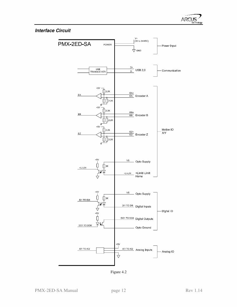
DELAY
Description:
Set a delay (1 ms units)
Syntax:
Delay=[Number] (1 ms units)
Examples:
JOGX+ ;***Jogs X axis to positive direction
DELAY=10000 ;***Wait 10 second
ABORT ;***Stop with deceleration all axes including X axis
EX=0 ;***Sets the current X encoder position to 0
EY=0 ;***Sets the current Y encoder position to 0
DI
Description:
Read: Gets the digital input value
Performax 2ED has 8 digital inputs
Syntax:
Read: [variable] = DI
Conditional: IF DI=[variable]
ENDIF
IF DI=[value]
ENDIF
Examples:
IF DI=255
DO=1 ;***If all digital inputs are triggered, set DO=1
ENDIF
DI[1-8]
Description:
Read: Gets the digital input value
Performax 2ED has 8 digital inputs
Syntax:
Read: [variable] = DI[1-8]
Conditional: IF DI[1-8]=[variable]
ENDIF
IF DI[1-8]=[0 or 1]
ENDIF
Examples:
IF DI1=1
DO=1 ;***If digital input 1 is triggered, set DO=1
ENDIF

PMX-2ED-SA Manual page 53 Rev 1.14
DO
Description:
Read: Gets the digital output value
Write: Sets the digital output value
Performax 2ED has 8 digital outputs
Syntax:
Read: [variable] = DO
Write: DO = [value]
DO = [variable]
Conditional: IF DO=[variable]
ENDIF
IF DO=[value]
ENDIF
Examples:
DO=7 ;***Turn first 3 bits on and rest off
DO[1-8]
Description:
Read: Gets the individual digital output value
Write: Sets the individual digital output value
Performax 2ED has 8 digital outputs
Syntax:
Read: [variable] = DO[1-8]
Write: DO[1-8] = [0 or 1]
DO[1-8] = [variable]
Conditional: IF DO[1-8]=[variable]
ENDIF
IF DO[1-8]=[0 or 1]
ENDIF
Examples:
DO7=1 ;***Turn DO7 on
DO6=1 ;***Turn DO6 on
E[axis]
Description:
Read: Gets the current encoder position
Write: Sets the current encoder position
Syntax:
Read: [variable] = E[axis]
Write: E[axis] = [value]
E[axis] = [variable]

PMX-2ED-SA Manual page 54 Rev 1.14
Conditional: IF E[axis]=[variable]
ENDIF
IF E[axis]=[value]
ENDIF
Examples:
JOGX+ ;***Jogs X axis to positive direction
DELAY=1000 ;***Wait 1 second
ABORT ;***Stop with deceleration all axes including X axis
EX=0 ;***Sets the current X encoder position to 0
EY=0 ;***Sets the current Y encoder position to 0
ECLEAR[axis]
Description:
Write: Clears error status
Syntax:
Write: ECLEAR[axis]
Examples:
ECLEARX ;***Clears error of axis X
ECLEARY ;***Clears error of axis Y
ELSE
Description:
Perform ELSE condition check as a part of IF statement
Syntax:
ELSE
Examples:
IF V1=1
X1000 ;***If V1 is 1, then move to 1000
WAITX
ELSE
X-1000 ;***If V1 is not 1, then move to -1000
WAITX
ENDIF
ELSEIF
Description:
Perform ELSEIF condition check as a part of the IF statement
Syntax:
ELSEIF [Argument 1] [Comparison] [Argument 2]
[Argument] can be any of the following:
Numerical value
Pulse or Encoder Position
Digital Output
Digital Input
Enable Output

PMX-2ED-SA Manual page 55 Rev 1.14
Motor Status
[Comparison] can be any of the following
= Equal to
> Greater than
< Less than
>= Greater than or equal to
<= Less than or equal to
!= Not Equal to
Examples:
IF V1=1
X1000
WAITX
ELSEIF V1=2
X2000
WAITX
ELSE
X0
WAITX
ENDIF
END
Description:
Indicate end of program.
Program status changes to idle when END is reached.
Note: Subroutine definitions should be written AFTER the END statement
Syntax:
END
Examples:
X0
WAITX
X1000
WAITX
END
ENDIF
Description:
Indicates end of IF operation
Syntax:
ENDIF
Examples:
IF V1=1
X1000
WAITX
ENDIF

PMX-2ED-SA Manual page 56 Rev 1.14
ENDSUB
Description:
Indicates end of subroutine
When ENDSUB is reached, the program returns to the previously called
subroutine.
Note : Subroutine 31 is reserved for error handling
Syntax:
ENDSUB
Examples:
GOSUB 1
END
SUB 1
X0
WAITX
ENDSUB
ENDWHILE
Description:
Indicate end of WHILE loop
Syntax:
ENDWHILE
Examples:
WHILE V1=1 ;***While V1 is 1 continue to loop
X0
WAITX
X1000
WAITX
ENDWHILE ;***End of while loop so go back to WHILE
EO
Description:
Read: Gets the enable output value
Write: Sets the enable output value
Performax 2ED has 2 enable outputs.
Syntax:
Read: [variable] = EO
Write: EO = [value]
EO = [variable]
Conditional: IF EO=[variable]
ENDIF
IF EO=[value]
ENDIF

PMX-2ED-SA Manual page 57 Rev 1.14
Examples:
EO=3 ;***Turn all 2 bits of enable outputs
IF V1=1
EO=V2 ;***Enable output according to variable 2
ENDIF
EO[1-2]
Description:
Read: Gets the individual enable output value
Write: Sets the individual enable output value
Performax 2ED has 4 enable outputs.
Syntax:
Read: [variable] = EO[1-2]
Write: EO[1-2] = [0 or 1]
EO[1-2] = [variable]
Conditional: IF EO=[variable]
ENDIF
IF EO=[value]
ENDIF
Examples:
EO1=1 ;***Turn enable output 1 on
IF V1=1
EO2=V2 ;***Enable output 2 according to variable 2
ENDIF
GOSUB
Description:
Perform go to subroutine operation
Subroutine range is from 1 to 32.
Note: Subroutine definitions should be written AFTER the END statement
Note : Subroutine 31 is reserved for error handling
Syntax:
GOSUB [subroutine number]
[Subroutine Number] range is 1 to 32
Examples:
GOSUB 1
END
SUB 1
X0
WAITX
ENDSUB

PMX-2ED-SA Manual page 58 Rev 1.14
HLHOME[axis][+ or -]
Description:
Command: Perform low speed homing using current high speed, low speed, and
acceleration.
Syntax:
HLHOME[Axis][+ or -]
Examples:
HLHOMEX+ ;***Low speed homes X axis in positive direction
WAITX
HLHOMEY- ;***Low speed homes Y axis in negative direction
WAITY
HOME[axis][+ or -]
Description:
Command: Perform homing using current high speed, low speed, and
acceleration.
Syntax:
HOME[Axis][+ or -]
Examples:
HOMEX+ ;***Homes X axis in positive direction
HOMEY- ;***Homes Y axis in negative direction
HSPD
Description:
Read: Gets high speed. Value is in pulses/second
Write: Sets high speed. Value is in pulses/second.
Range is from 1 to 6,000,000.
Syntax:
Read: [variable] = HSPD
Write: HSPD = [value]
HSPD = [variable]
Conditional: IF HSPD=[variable]
ENDIF
IF HSPD=[value]
ENDIF
Examples:
HSPD=10000 ;***Sets the high speed to 10,000 pulses/sec
V1=2500 ;***Sets the variable 1 to 2,500
HSPD=V1 ;***Sets the high speed to variable 1 value of 250
HSPD[axis]
Description:
Read: Gets individual high speed. Value is in pulses/second
Write: Sets individual high speed. Value is in pulses/second.
Range is from 1 to 6,000,000.
Syntax:

PMX-2ED-SA Manual page 59 Rev 1.14
Read: [variable] = HSPD[axis]
Write: HSPD[axis] = [value]
HSPD[axis] = [variable]
Conditional: IF HSPD[axis]=[variable]
ENDIF
IF HSPD[axis]=[value]
ENDIF
Examples:
HSPDY=10000 ;***Sets the Y high speed to 10,000 pulses/sec
V1=2500 ;***Sets the variable 1 to 2,500
HSPDY=V1 ;***Sets the Y high speed to variable 1 value of 2500
IF
Description:
Perform IF condition check
Syntax:
IF [Argument 1] [Comparison] [Argument 2]
[Argument] can be any of the following:
Numerical value
Pulse or Encoder Position
Digital Output
Digital Input
Enable Output
Motor Status
[Comparison] can be any of the following
= Equal to
> Greater than
< Less than
>= Greater than or equal to
<= Less than or equal to
!= Not Equal to
Examples:
IF V1=1
X1000
WAITX
ENDIF
INC
Description:
Command: Changes all move commands to incremental mode.
Syntax:
INC
Examples:
ABS ;***Change to absolute mode
PX=0 ;***Change X position to 0

PMX-2ED-SA Manual page 60 Rev 1.14
X1000 ;***Move X axis to position 1000 (0+1000)
WAITX
X2000 ;***Move X axis to position 3000 (1000+2000)
WAITX
ABORT ;***Stop immediately all axes including X axis
JOG[axis]
Description:
Command: Perform jogging using current high speed, low speed, and
acceleration.
Syntax:
JOG[Axis][+ or -]
Examples:
JOGX+ ;***Jogs X axis in positive direction
JOGY- ;***Jogs Y axis in negative direction
JOYENA
Description:
Write: Enable joystick feature for axis
Syntax:
Write: JOYENA=[0,1]
Examples:
JOYENA=1 ;***Enable joystick feature on X axis only
JOYHS[axis]
Description:
Write: Set high speed setting for joystick control
Syntax:
Write: JOYHS[axis] = [value]
JOYHS[axis] = [variable]
Examples:
JOYHSX=10000 ;***High speed of X axis is set to 10,000 pps
JOYHSY=20000 ;***High speed of Y axis is set to 20,000 pps
JOYDEL[axis]
Description:
Write: Set maximum delta value of change in speed for joystick control
Syntax:
Write: JOYDEL[axis] = [value]
JOYDELaxis] = [variable]
Examples:
JOYDELX=100 ;***Speed delta of X axis is set to 100 pps
JOYDELY=200 ;***Speed delta of Y axis is set to 200 pps

PMX-2ED-SA Manual page 61 Rev 1.14
JOYNO[axis]
Description:
Write: Set negative outer limit for joystick control
Syntax:
Write: JOYNO[axis] = [value]
JOYNO[axis] = [variable]
Examples:
JOYNOX=-10000 ;*** negative outer limit of x-axis set to -10000
JOYNIX=-9000 ;*** negative inner limit of x-axis set to -9000
JOYPIX=9000 ;*** positive inner limit of x-axis set to 9000
JOYPOX=10000 ;*** positive outer limit of x-axis set to 10000
JOYNI[axis]
Description:
Write: Set negative inner limit for joystick control
Syntax:
Write: JOYNI[axis] = [value]
JOYNI[axis] = [variable]
Examples:
JOYNOX=-10000 ;*** negative outer limit of x-axis set to -10000
JOYNIX=-9000 ;*** negative inner limit of x-axis set to -9000
JOYPIX=9000 ;*** positive inner limit of x-axis set to 9000
JOYPOX=10000 ;*** positive outer limit of x-axis set to 10000
JOYPI[axis]
Description:
Write: Set positive inner limit for joystick control
Syntax:
Write: JOYPI[axis] = [value]
JOYPI[axis] = [variable]
Examples:
JOYNOX=-10000 ;*** negative outer limit of x-axis set to -10000
JOYNIX=-9000 ;*** negative inner limit of x-axis set to -9000
JOYPIX=9000 ;*** positive inner limit of x-axis set to 9000
JOYPOX=10000 ;*** positive outer limit of x-axis set to 10000
JOYPO[axis]
Description:
Write: Set positive outer limit for joystick control
Syntax:
Write: JOYPO[axis] = [value]
JOYPO[axis] = [variable]
Examples:
JOYNOX=-10000 ;*** negative outer limit of x-axis set to -10000
JOYNIX=-9000 ;*** negative inner limit of x-axis set to -9000
JOYPIX=9000 ;*** positive inner limit of x-axis set to 9000

PMX-2ED-SA Manual page 62 Rev 1.14
JOYPOX=10000 ;*** positive outer limit of x-axis set to 10000
JOYTOL[axis]
Description:
Write: Set zero tolerance value for joystick control
Syntax:
Write: JOYTOL[axis] = [value]
JOYTOL[axis] = [variable]
Examples:
JOYTOLX=10 ;*** zero tolerance value of x-axis set to 10
LHOME[axis][+ or -]
Description:
Command: Perform limit homing using current high speed, low speed, and
acceleration.
Syntax:
LHOME[Axis][+ or -]
Examples:
LHOMEX+ ;***Limit homes X axis in positive direction
WAITX
LHOMEY- ;***Limit homes Y axis in negative direction
LSPD
Description:
Read: Get low speed. Value is in pulses/second.
Write: Set low speed. Value is in pulses/second.
Syntax:
Read: [variable]=LSPD
Write: LSPD=[long value]
LSPD=[variable]
Conditional: IF LSPD=[variable]
ENDIF
IF LSPD=[value]
ENDIF
Examples:
LSPD=1000 ;***Sets the start low speed to 1,000 pulses/sec
V1=500 ;***Sets the variable 1 to 500
LSPD=V1 ;***Sets the start low speed to variable 1 value of 500
LSPD[axis]
Description:
Read: Get individual low speed. Value is in pulses/second.
Write: Set individual low speed. Value is in pulses/second.
Syntax:
Read: [variable]=LSPD[axis]

PMX-2ED-SA Manual page 63 Rev 1.14
Write: LSPD[axis]=[long value]
LSPD[axis]=[variable]
Conditional: IF LSPD[axis]=[variable]
ENDIF
IF LSPD[axis]=[value]
ENDIF
Examples:
LSPDX=1000 ;***Sets the X low speed to 1,000 pulses/sec
V1=500 ;***Sets the variable 1 to 500
LSPDX=V1 ;***Sets the X low speed to variable 1 value of 500
MST[axis]
Description:
Command: Get motor status of axis
Syntax:
MST[Axis]
Examples:
IF MSTX=0
DO=6
ELSEIF MSTY=0
DO=3
ENDIF
P[axis]
Description:
Read: Gets the current pulse position
Write: Sets the current pulse position
Syntax:
Read: Variable = P[axis]
Write: P[axis] = [value]
P[axis] = [variable]
Conditional: IF P[axis]=[variable]
ENDIF
IF P[axis]=[value]
ENDIF
Examples:
JOGX+ ;***Jogs X axis to positive direction
DELAY=1000 ;***Wait 1 second
ABORT ;***Stop with deceleration all axes including X axis
PX=0 ;***Sets the current pulse position to 0
PRG
Description:
Indicates the start of a program
When END is reached, the program is concluded
Syntax:

PMX-2ED-SA Manual page 64 Rev 1.14
PRG [program number]
Examples:
PRG 0 ;***Program 0
X8000
WAITX
END
PRG 1 ;***Program 1
Y1000
WAITY
END
PS[axis]
Description:
Read: Get the current pulse position of an axis
Syntax:
Read: Variable = PS[Axis]
Conditional: IF PS[axis]=[variable]
ENDIF
IF PS[axis]=[value]
ENDIF
Examples:
JOGX+ ;***Jogs X axis to positive direction
DELAY=1000 ;***Wait 1 second
ABORT ;***Stop with deceleration all axes including X axis
V1=PSX ;***Sets variable 1 to pulse X
JOGY+ ;***Jogs Y axis to positive direction
V2=PSY ;***Sets variable 2 to pulse Y
SCV[axis]
Description:
Read: Get individual s-curve enable. Value is 0 or 1.
Write: Set individual s-curve enable.
Range is from 0 or 1
Syntax:
Read: [variable]=SCV[axis]
Write: SCV[axis]=[0 or 1]
SCV[axis]=[variable]
Note: If s-curve is enabled for an axis, on-the-fly speed feature can not be used for the
corresponding axis.
Examples:
SCVX=1 ;***Sets X axis to use s-curve acceleration: on-the-fly speed ; ;
; change is NOT allowed for this axis.
SCVY=0 ;***Sets Y axis to use s-curve acceleration: on-the-fly speed ; ;
; change is allowed for this axis.

PMX-2ED-SA Manual page 65 Rev 1.14
SL[axis]
Description:
Write: Set individual StepNLoop enable.
Range is from 0 or 1
Syntax:
Write: SL[axis]=[0 or 1]
Examples:
SLX=1 ;***Enables StepNLoop control for the X axis.
SLY=0 ;***Disables StepNLoop control for the Y axis.
SLS[axis]
Description:
Command: Get the StepNLoop status of axis
Syntax:
SLS[Axis]
V[Value] = SLS[Axis]
Examples:
IF SLSX=0
DO=6
ELSEIF SLSY=0
DO=3
ENDIF
SR[0,1]
Description:
Write: Set the standalone control for the specified standalone program
Syntax:
Write: SR[0-1] = [0-3]
SR[0-1] = [0-3]
Examples:
IF DI1=1 ; If digital input 1 is on
SR0=0 ; Turn off standalone program 0
ENDIF
SSPD[axis]
Description:
Write: Set on-the-fly speed change for an individual axis.
Range is from 1 to 6,000,000 PPS
Syntax:
Write: SSPD[axis]=[value]
SSPD[axis]=[variable]
Note: If s-curve is enabled for an axis, on-the-fly speed feature can not be used for the
corresponding axis.
Examples:
SCVX=0 ;***Disable s-curve acceleration for X-axis
HSPDX=1000 ;***X-axis high speed

PMX-2ED-SA Manual page 66 Rev 1.14
LSPDX=100 ;***Set X-axis low speed
ACCX=100 ;***Set X-axis acceleration
JOGX+ ;***Jogs X axis to positive direction
DELAY=1000 ;***Wait 1 second
SSPDX=3000 ;***Change speed on X-axis on-the-fly to 3000 PPS
SSPDM[axis]
Description:
Write: Set individual on-the-fly speed change mode. Range is from 0 to 9.
Syntax:
Write: SSPDM[axis]=[0-9]
SSPDM[axis]=[variable]
Examples:
SCVX=0 ;***Disable s-curve acceleration for X-axis
HSPDX=1000 ;***X-axis high speed
LSPDX=100 ;***Set X-axis low speed
ACCX=100 ;***Set X-axis acceleration
JOGX+ ;***Jogs X axis to positive direction
DELAY=1000 ;***Wait 1 second
SSPDMX=1 ;***Set on-the-fly speed change mode to 1
ACCX=20000 ;***Set acceleration to 20 seconds
SSPDX=190000 ;***Change speed on X-axis on-the-fly to 190000 PPS
STOP
Description:
Command: Stop all axes if in motion with deceleration.
Previous acceleration value is used for deceleration.
Syntax:
STOP
Examples:
JOGX+ ;***Jogs X axis to positive direction
DELAY=1000 ;***Wait 1 second
STOP ;***Stop with deceleration all axes including X axis
STOP[axis]
Description:
Stop individual axis if in motion with deceleration.
Previous acceleration value is used for deceleration.
Syntax:
STOP[axis]
Examples:
JOGX+ ;***Jogs X axis to positive direction
DELAY=1000 ;***Wait 1 second
JOGY+ ;***Jogs Y axis to positive direction
DELAY=1000 ;***Wait 1 second
STOPX ;***Stop with deceleration X axis only

PMX-2ED-SA Manual page 67 Rev 1.14
STORE
Description:
Store device settings and the second half of variables (V32-V63) to flash.
Syntax:
STORE
Example:
V32=100
V33=200
STORE ;***Values of V1 and V2 will now be preserved after power cycle
SUB
Description:
Indicates start of subroutine
Syntax:
SUB [subroutine number]
[Subroutine Number] range is 0 to 31
Note : Subroutine 31 is reserved for error handling
Examples:
GOSUB 1
END
SUB 1
X0
WAITX
X1000
WAITX
ENDSUB
TOC
Description:
Sets the communication time-out parameter. Value is in milli-seconds.
Syntax:
TOC=[long value]
Examples:
TOC=10000 ;***Sets time-out parameter to 10 seconds
V
Description:
Assign to variable.
Performax 2ED has 64 variables [V0-V63]
Syntax:
V[Variable Number] = [Argument]
V[Variable Number] = [Argument1][Operation][Argument2]
Special case for BIT NOT:
V[Variable Number] = ~[Argument]
[Argument] can be any of the following:

PMX-2ED-SA Manual page 68 Rev 1.14
Numerical value
Pulse or Encoder Position
Digital Output
Digital Input
Enable Output
Motor Status
[Operation] can be any of the following
+ Addition
- Subtraction
* Multiplication
/ Division
% Modulus
>> Bit Shift Right
<< Bit Shift Left
& Bit AND
| Bit OR
~ Bit NOT
Examples:
V1=12345 ;***Set Variable 1 to 123
V2=V1+1 ;***Set Variable 2 to V1 plus 1
V3=DI ;***Set Variable 3 to digital input value
V4=DO ;***Sets Variable 4 to digital output value
V5=~EO ;***Sets Variable 5 to bit NOT of enable output value
Note: On the STORE command, the second half of general purpose variable registers
(V32-V63) are stored to flash. Their values will be preserved after power cycle.
WAIT
Description:
Tell program to wait until move on the certain axis is finished before executing
next line.
Syntax:
WAIT[axis]
X[variable]
Examples:
X10000 ;***Move X Axis to position 10000
WAITX ;***Wait until X Axis move is done
DO=5 ;***Set digital output
Y3000 ;***Move Y Axis to 3000
WAITY ;***Wait until Y Axis move is done
WHILE
Description:
Perform WHILE loop
Syntax:
WHILE [Argument 1] [Comparison] [Argument 2]

PMX-2ED-SA Manual page 69 Rev 1.14
[Argument] can be any of the following:
Numerical value
Pulse or Encoder Position
Digital Output
Digital Input
Enable Output
Motor Status
[Comparison] can be any of the following
= Equal to
> Greater than
< Less than
>= Greater than or equal to
<= Less than or equal to
!= Not Equal to
Examples:
WHILE V1=1 ;***While V1 is 1 continue to loop
X0
WAITX
X1000
WAITX
ENDWHILE
X
Description:
Command: Perform X axis move to target location
With other Axis moves in the same line, linear interpolation move is done.
Syntax:
X[value]
X[variable]
Examples:
X10000 ;***Move X Axis to position 10000
WAITX
X2000Y3000 ;***Move X to 2000 and Y to 3000 in linear interpolation move
WAITX
V10 = 1200 ;***Set variable 10 value to 1200
XV10 ;***Move X Axis to variable 10 value
WAITX
Y
Description:
Command: Perform Y axis move to target location
With other Axis moves in the same line, linear interpolation move is done.
Syntax:
Y[value]
Y[variable]
Examples:

PMX-2ED-SA Manual page 70 Rev 1.14
Y10000 ;***Move Y Axis to position 10000
WAITY
X2000Y3000 ;***Move X to 2000 and Y to 3000 in linear interpolation move
WAITX
V10 = 1200 ;***Set variable 10 value to 1200
YV10 ;***Move Y Axis to variable 10 value
WAITY
ZHOME[axis][+ or -]
Description:
Command: Perform Z-homing using current high speed, low speed, and
acceleration.
Syntax:
ZHOME[Axis][+ or -]
Examples:
ZHOMEX+ ;***Z Homes X axis in positive direction
ZHOMEY- ;***Z Homes Yaxis in negative direction
ZOME[axis][+ or -]
Description:
Command: Perform Zoming using current high speed, low speed, and
acceleration.
Syntax:
ZOME[Axis][+ or -]
Examples:
ZOMEX+ ;***Homes X axis in positive direction
ZOMEY- ;***Homes Y axis in negative direction

PMX-2ED-SA Manual page 71 Rev 1.14
10. Example Standalone Programs
Standalone Example Program 1 – Single Thread
Task: Set the high speed and low speed and move the motor to 1000 and back to 0.
HSPD=20000 ;* Set the high speed to 20000 pulses/sec
LSPD=1000 ;* Set the low speed to 1000 pulses/sec
ACC=300 ;* Set the acceleration to 300 msec
EO=1 ;* Enable the motor power
X1000 ;* Move to 1000
WAITX ;*Wait for X-axis move to complete
X0 ;* Move to zero
WAITX ;*Wait for X-axis move to complete
END ;* End of the program
Standalone Example Program 2 – Single Thread
Task: Move the motor back and forth indefinitely between position 1000 and 0.
HSPD=20000 ;* Set the high speed to 20000 pulses/sec
LSPD=1000 ;* Set the low speed to 1000 pulses/sec
ACC=300 ;* Set the acceleration to 300 msec
EO=1 ;* Enable the motor power
WHILE 1=1 ;* Forever loop
X0 ;* Move to zero
WAITX ;*Wait for X-axis move to complete
X1000 ;* Move to 1000
WAITX ;*Wait for X-axis move to complete
ENDWHILE ;* Go back to WHILE statement
END
Standalone Example Program 3 – Single Thread
Task: Move the motor back and forth 10 times between position 1000 and 0.
HSPD=20000 ;* Set the high speed to 20000 pulses/sec
LSPD=1000 ;* Set the low speed to 1000 pulses/sec
ACC=300 ;* Set the acceleration to 300 msec
EO=1 ;* Enable the motor power
V1=0 ;* Set variable 1 to value 0
WHILE V1<10 ;* Loop while variable 1 is less than 10
X0 ;* Move to zero
WAITX ;*Wait for X-axis move to complete
X1000 ;* Move to 1000
WAITX ;*Wait for X-axis move to complete
V1=V1+1 ;* Increment variable 1
ENDWHILE ;* Go back to WHILE statement
END

PMX-2ED-SA Manual page 72 Rev 1.14
Standalone Example Program 4 – Single Thread
Task: Move the motor back and forth between position 1000 and 0 only if the digital
input 1 is turned on.
HSPD=20000 ;* Set the high speed to 20000 pulses/sec
LSPD=1000 ;* Set the low speed to 1000 pulses/sec
ACC=300 ;* Set the acceleration to 300 msec
EO=1 ;* Enable the motor power
WHILE 1=1 ;* Forever loop
IF DI1=1 ;* If digital input 1 is on, execute the statements
X0 ;* Move to zero
WAITX ;*Wait for X-axis move to complete
X1000 ;* Move to 1000
WAITX ;*Wait for X-axis move to complete
ENDIF
ENDWHILE ;* Go back to WHILE statement
END
Standalone Example Program 5 – Single Thread
Task: Using a subroutine, increment the motor by 1000 whenever the DI1 rising edge is
detected.
HSPD=20000 ;* Set the high speed to 20000 pulses/sec
LSPD=1000 ;* Set the low speed to 1000 pulses/sec
ACC=300 ;* Set the acceleration to 300 msec
EO=1 ;* Enable the motor power
V1=0 ;* Set variable 1 to zero
WHILE 1=1 ;* Forever loop
IF DI1=1 ;* If digital input 1 is on, execute the statements
GOSUB 1 ;* Move to zero
ENDIF
ENDWHILE ;* Go back to WHILE statement
END
SUB 1
XV1 ;* Move to V1 target position
WAITX ;*Wait for X-axis move to complete
V1=V1+1000 ;* Increment V1 by 1000
WHILE DI1=1 ;* Wait until the DI1 is turned off so that
ENDWHILE ;* 1000 increment is not continuously done
ENDSUB

PMX-2ED-SA Manual page 73 Rev 1.14
Standalone Example Program 6 – Single Thread
Task: If digital input 1 is on, move to position 1000. If digital input 2 is on, move to
position 2000. If digital input 3 is on, move to 3000. If digital input 5 is on, home the
motor in negative direction. Use digital output 1 to indicate that the motor is moving or
not moving.
HSPD=20000 ;* Set the high speed to 20000 pulses/sec
LSPD=1000 ;* Set the low speed to 1000 pulses/sec
ACC=300 ;* Set the acceleration to 300 msec
EO=1 ;* Enable the motor power
WHILE 1=1 ;* Forever loop
IF DI1=1 ;* If digital input 1 is on
X1000 ;* Move to 1000
WAITX ;*Wait for X-axis move to complete
ELSEIF DI2=1 ;* If digital input 2 is on
X2000 ;* Move to 2000
WAITX ;*Wait for X-axis move to complete
ELSEIF DI3=1 ;* If digital input 3 is on
X3000 ;* Move to 3000
WAITX ;*Wait for X-axis move to complete
ELSEIF DI5=1 ;* If digital input 5 is on
HOMEX- ;* Home the motor in negative direction
WAITX ;*Wait for X-axis move to complete
ENDIF
V1=MSTX ;* Store the motor status to variable 1
V2=V1&7 ;* Get first 3 bits
IF V2!=0
DO1=1
ELSE
DO1=0
ENDIF
ENDWHILE ;* Go back to WHILE statement
END

PMX-2ED-SA Manual page 74 Rev 1.14
Standalone Example Program 7 – Multi Thread
Task: Program 0 will continuously move the motor between positions 0 and 1000.
Simultaneously, program 1 will control the status of program 0 using digital inputs.
PRG 0 ;* Start of Program 0
HSPD=20000 ;* Set high speed to 20000pps
LSPD=500 ;* Set low speed to 500pps
ACC=500 ;* Set acceleration to 500ms
WHILE 1=1 ;* Forever loop
X0 ;* Move to position 0
WAITX ;* Wait for the move to complete
X1000 ;* Move to position 1000
WAITX ;* Wait for the move to complete
ENDWHILE ;* Go back to WHILE statement
END ;* End Program 0
PRG 1 ;* Start of Program 1
WHILE 1=1 ;* Forever loop
IF DI1=1 ;* If digital input 1 is triggered
ABORTX ;* Stop movement
SR0=0 ;* Stop Program 1
ELSE ;* If digital input 1 is not triggered
SR0=1 ;* Run Program 1
ENDIF ;* End if statements
ENDWHILE ;* Go back to WHILE statement
END ;* End Program 1

PMX-2ED-SA Manual page 75 Rev 1.14
Standalone Example Program 8 – Multi Thread
Task: Program 0 will continuously move the motor between positions 0 and 1000.
Simultaneously, program 1 will monitor the communication time-out parameter and
triggers digital output 1 if a time-out occurs. Program 1 will also stop all motion, disable
program 0 and then re-enable it after a delay of 3 seconds when the error occurs.
PRG 0 ;* Start of Program 0
HSPD=1000 ;* Set high speed to 1000 pps
LSPD=500 ;* Set low speed to 500pps
ACC=500 ;* Set acceleration to 500ms
TOC=5000 ;* Set time-out counter alarm to 5 seconds
EO=1 ;* Enable motor
WHILE 1=1 ;* Forever loop
X0 ;* Move to position 0
WAITX ;* Wait for the move to complete
X1000 ;* Move to position 1000
WAITX ;* Wait for the move to complete
ENDWHILE ;* Go back to WHILE statement
END ;* End Program 0
PRG 1 ;* Start of Program 1
WHILE 1=1 ;* Forever loop
V1=MSTX&2048 ;* Get bit time-out counter alarm variable
IF V1 = 2048 ;* If time-out counter alarm is on
SR0=0 ;* Stop program 0
ABORTX ;* Abort the motor
DO=0 ;* Set DO=0
DELAY=3000;* Delay 3 seconds
SR0=1 ;* Turn program 0 back on
DO=1 ;* Set DO=1
ENDIF
ENDWHILE ;* Go back to WHILE statement
END ;* End Program 1

PMX-2ED-SA Manual page 76 Rev 1.14
Appendix A: Speed Settings
HSPD value
[PPS] †
Speed
Window
[SSPDM]
Min.
LSPD
value
Min. ACC
[ms] δ Max ACC setting [ms]
1 - 16K 0,1 1 1 300
((HSPD – LSPD) / δ) × 1000
16k - 32K 2 2 1 775
32K - 80K 3 5 1 1,900
80K - 160K 4 10 1 3,700
160K - 325K 5 20 1 7,300
325K - 815K 6 50 1 18,000
815K - 1.6M 7 100 1 38,400
1.6M - 3.2M 8 200 1 68,000
3.2M - 6M 9 400 1 135,000
Table A.0
†If StepNLoop is enabled, the [HSPD range] values needs to be transposed from PPS (pulse/sec)
to EPS (encoder counts/sec) using the following formula:
EPS = PPS / Step-N-Loop Ratio
Acceleration/Deceleration Range
The allowable acceleration/deceleration values depend on the LS and HS settings.
The minimum acceleration/deceleration setting for a given high speed and low speed is
shown in Table A.0.
The maximum acceleration/deceleration setting for a given high speed and low speed can
be calculated using the formula:
Note: The ACC parameter will be automatically adjusted if the value exceeds the
allowable range.
Max ACC = ((HS – LS) / δ) × 1000 [ms]
Figure A.0
Examples:
a) If HSPD = 20,000 pps, LSPD = 10,000 pps:
a. Min acceleration allowable: 1 ms
b. Max acceleration allowable:
((20,000 – 10000) / 775) x 1,000 ms = 12,903 ms (12.9 sec)
b) If HSPD = 900,000 pps, LSPD = 9,000 pps:

PMX-2ED-SA Manual page 77 Rev 1.14
a. Min acceleration allowable: 1 ms
b. Max acceleration allowable:
((900,000 – 9,000) / 38,400) x 1000 ms = 23,203 ms (23.3 sec)
Acceleration/Deceleration Range – Positional Move
When dealing with positional moves, the controller automatically calculates the
appropriate acceleration and deceleration based on the following rules.
Figure A.1
1) ACC vs. DEC 1: If the theoretical position where the controller begins
deceleration is less than L/2, the acceleration value is used for both ramp up and
ramp down. This is regardless of the EDEC setting.
2) ACC vs. DEC 2: If the theoretical position where the controller begins constant
speed is greater than L/2, the acceleration value is used for both ramp up and
ramp down. This is regardless of the EDEC setting.
3) Triangle Profile: If either (1) or (2) occur, the velocity profile becomes triangle.
Maximum speed is reached at L/2.

PMX-2ED-SA Manual page 78 Rev 1.14
Contact Information
Arcus Technology, Inc.
3159 Independence Dr Livermore, CA 94551
925-373-8800
www.arcustechnology.com
The information in this document is believed to be accurate at the time of publication but is subject to
change without notice.
Related Documents