!~ NUREG/CR-2892 i i 1 : : : ! Performance Testing of Personnel Dosimetry Services 1 : : J : A Revised Procedures Manual ; * i - Preoared by J. Miklos, P. Plato i The University of Michigan i School of Public Health , Prepared for U.S. Nuclear Regulatory Commission ; 4 i ! i : I ; ! ! : ; e303100453 830228 bR-2 2R PDR , -,-,--,_ .-.,- .n. ,,-.-,,,r.,- e- - - - - . - , _ ,- ,,n-,-,-.- , , . .., -- .- .-,,. , , . - , - ,, , , _ , _ ,-- - - . . , , , , , - . , , --

Welcome message from author
This document is posted to help you gain knowledge. Please leave a comment to let me know what you think about it! Share it to your friends and learn new things together.
Transcript
!~ NUREG/CR-2892
ii1
::
:
! Performance Testing ofPersonnel Dosimetry Services
1
:
:J
: A Revised Procedures Manual;
*
i-
Preoared by J. Miklos, P. Plato
i
The University of Michigani
School of Public Health,
Prepared forU.S. Nuclear RegulatoryCommission;
4
i
!
i
:
I;
!!
:;
e303100453 830228bR-2 2R PDR
,
-,-,--,_ .-.,- .n. ,,-.-,,,r.,- e- - - - - . - , _ ,- ,,n-,-,-.- , , . .., -- .- .-,,. , , . - , - ,, , , _ , _ ,-- - - . . , , , , , - . ,, --
l
If
NOTICE
This report was prepared as an account of work sponsored by an agency of the United StatesGovernment. Neither the United States Government nor any agency thereof, or any of theiremployees, makes any warranty, expressed or implied, or assumes ariy legal liability of re-sponsibility for any third party's use, or the results of such use, of any information, apparatus,product or process disclosed in this report, or represents that its use by sucf. third party wouldnot infringe privately owned rights.
Availability of Reference Materials Cited in NRC Publica* ions
Most docunients cited in NRC publications will be available from one of the following sources:
1. The NRC Public Document Room,1717 H Street, N.W.Washington, DC 20555
,
2 The NRC/GPO Sales Program, U.S. Nuclear Regulatory Commission,Washington, DC 20555'
3. The National Technical Information Service, Springfield, VA 22161
Although the listing that follows represents the majority of documents cited in NRC publications,it is not intended to be exhaustive.
Referenced docurnents available for inspection and copying for a fee from the NRC Public Docu-ment Room include NRC correspondence and ir.ternal NRC memoranda; NRC Office of Inspectionand Enforcement bulletins. circulars, information notices, inspection and investigation notices;Licensee Event Reports, vendor reports and correspondence, Commission papers; and applicant andlicensee documents and correspondence.
j
The following documents in the NUREG series are available for purchase from the NRC/GPO SalesProgram; formal NRC staff and contractor reports. NRC sponsored conference proceedings, andNRC booklets and brochures. Also available are Regulatory Guides, NRC regulations in the Code o/Federal Regulations, and Nuclear Regulatory Commission Issuances.
,
Documents available from the National Technical Information Service include NUREG seriesreports and technical reports prepared by other federal agencies and reports prepared by the Atomic
4
|Energy Commission, forerunner agency to the Nuclear Regulatory Commission.
Documants available from public and special technical libraries include all open literature items,such as books ournal and periodical articles, and transactions. Federal Reg / ster notices. federal andstate legislation, and congressional reports can usually be obtained from these libraries.
Documents such as theses, dissertations, foreign reports and translations, and non NRC conferenceI
proceedings are available for purchase from the organization sponsoring the pubhcation cited.|
Singie copics of NRC draft reports are available free upon written request to the Division of Tech.$nical Information and Document Control, U S. Nuclear Regulatory Commission. Washington, DC
20555
Copies of industry codes and standards used iri a substantive manner in the NRC regulatory processare maintained at the NRC Library, 7920 Norfolk . avenue. Bethesaa. Maryland and are availablethere for reference use by the pubhc Codes and stanoJrds Jre usually Copyrighted and may bepurchased from the originating organstation or, if they are American National Standards, from theAmerican National Standards institute.1430 Broadway. New York. NY 10018.
__
_
*
GPO Ponted copy pra.e
:
!NUREG/CR-2892 l
1|
_ _ _ _ _ _
Performance Testing ofPersonnel Dosimetry Services
|,
1
A Revised Procedures Manual
. - .- - __ - ____-.__-___
MInuscript Completed: November 1982D:te Published: February 1983
Prtpared byJ. Miklos. P. Plato
The University of MichiganSchool of Public HealthAnn Arbor, MI 48109
Pr: pared forDivision of Facility OperationsOffice of Nuclear Regulatory ResearchU.S. Nuclear Regulatory CommissionWcshington, D.C. 20666NRC FIN B1049
:
!
1
i
4
'. . _ _ . . - . - _ _ _ _ - . __
___._ ____ _ - _ . . _ -
PERFORMANCE TESTING OF PERSONNELDOSIMETRY SERVICES:
A REWSED PROCEDURES MANUAL
ABSTRACT
The U S. Nuclear Regulatory Commission's pilot study of the HealthPhysics Scciety Standards Committee Standard, " Criteria for Testing PersonnelDosimetry Performance," was begun in 1977. A third test of this Standard wasconducted from November,1981 through April,1982.
The objective of this Procedures Manual is to describe the proceduresused for Test #3 which reflect the changes in the Standard from Tests #1 and# 2. This Manual describes each of the radiation sources used for Test #3, aswell as the administrative procedures used during the testing program. Methodsof irradiation, quality control, data analysis, record keeping, and handling large
! numbers of dosimeters are presented. This Manual discusses the role of the| National Bureau of Standards in verifying the validity of the calibration of each
radiation source.
Suggestions for improving irradiation procedures are included as well as| recommendations that will facilitate the operation of the permanent testing| facility.
|
|
,
,
1
kkk
,-- -
.
TABLE OF CONTENTS
ABSTRACT iii~,
I. INTRODUCTION 1
II. INSTRUMENTATION AND EQUIPMENT 3
A. NBS Verification and Site Visits 3B. Dosimetry Instruments 3C. Phantoms and Phantom Alignment 5D. Instrument Intercomparison 7
III. RADIATION SOURCES 9
A. General 911. Iligh-Energy Photon Sources 11
1. 400 Ci cesium-137 beam irradiator 112. 20 Ci cesium-137 beam irradiator 1.
C. Low-Energy Photon Sources 17,
1. Maxitron 300 X-ray machine 182. XRD-5 X-ray diffraction unit 20
D. Deta-Particle Source 20D 0-moderated californium-252 Source 23 - >E. 2
j F. Radiation Safety 26
IV. CALCULATIONS OF DOSE EQUIVALENTS 29'
A. Photon Sources 29B. Deta-Particle Source 30C. Neutron Source 30
V. ADMINISTERING TIIE TEST<
3
A. Technician Training 32. B. Scheduling Test #3 Irradiations 32
C. Receiving and Organizing Dosimeters 33i
D. Irradiating Dosimeters 341 E. Returning Dosimeters 341 F. Analysis of Reported Dose Equivalents 35
G. Quality Control 36
VI. RECOM MENDATIONS 37,
Vll. ACKNOWLEDGEMENT 41,
||
| VIII. REFERENCES 42,
d
V
-- - - - - .- --,--- -, . . , . - . , ~.
r
TABLE OF CONTENTScontinued
APPENDIX A
The llPSSC Standard, adopted in June,1981' used forTest #3 of the Pilot Study.
APPENDIX B
NBS Site Visit Reports, prior to Tests #1 and #2 andprior to Test #3. (An itemization of this Appendixis given on its title page.)
APPENDIX C
Sample of all forms which document the flow ofinformation for Test #3 (from invitation to participatethrough report of results for a hypothetical processor).(An itemization of this 4ppendix is given on its titlepage.)
.
>
Vi
.-
- - - .
|
L q
'l''
I. INTRODUCTION .!
!
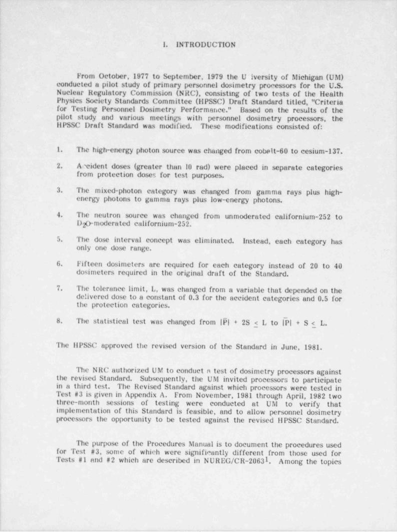
From October,1977 to September,1979 the U ~iversity of Michigan (UM)conducted a pilot study of primary personnel dosimetry processors for the U.S.Nuclear Regulatory Commission (NRC), consisting of two tests of the HealthPhysics Society Standards Committee (HPSSC) Draft Standard titled, " Criteriafor Testing Personnel Dosimetry Performance." Based on the results of thepilot study and various meetings with personnel dosimetry processors, . theHPSSC Draft Standard was modified. These modifications consisted of:
1. The high-energy photon source was changed from cobelt-60 to cesium-137.
2. Accident doses (greater than 10 rad) were placed in separate categoriesfrom protection doses for test purposes.
3. The mixed-photon category was changed from gamma rays plus high-energy photons to gamma rays plus low-energy _ photons.
'
4. The neutron source was changed from unmoderated californium-252 toD 0-moderated californium-252.2
| 5. The dose interval concept was eliminated. Instead, each category hasonly one dose range.
! 6. Fifteen dosimeters are required for each category instead of 20 to'40! dosimeters required in the original draft of the Standard.
7. The tolerance limit, L, was changed from a variable that depended on thedelivered dose to a constant of 0.3 for the accident categories and 0.5 for !
the protection categories.
The statistical test was c' anged from |PI + 2S < L to IPl + S < L'.8. h
The IIPSSC approved the revised version of the Standard in June,1981.
The NRC authorized UM to conduct n test of dosimetry processors againstthe revised Standard. Subsequently, the UM invited processors to participatein a third test. The Revised Standard against which processors were tested inTest #3 is given in Appendix A. From November,1981 through April,1982 twothree-month sessions of testing were conducted at UM to verify thatimplementation of this Standard is feasible, and to allow personnel dosimetryprocessors the opportunity to be tested against the revised HPSSC Standard.
L
| The purpose of the Procedures Manual is to document the procedures used |
- for Test #3, some of which were significantly different from those used forTests #1 and #2 which are described in NUREG/CR-2063 . Among the topics1
,
f. . _ _ - . . _ . . -- .-- .- .. - - -_
_
J
2,
covered are: measurement systems, radiation source calibrations, irradiationgeometries, execution of tests, dosimeter handling, record keeping, dataanalysis, and quality control. Recommendations for improving specificprocedures are included.
,
A description of the test categories, test irradiation ranges, and tolerancei
levels of the revised IIPSSC Standard are found in Table 1 in. Appendix A(pg. A.20). Table 2 in Appendix A .(pg. A.21) presents information on the
.
: NBS X-ray techniques available for use by the testing laboratory.
4
During June, 1982 the revised ilPSSC Standard was approved by theAmerican National Standards Institute.and designated ANSI N13.11-1982.
;
,
1
i
i
,,
,
t
_ . . ._ _ . . - _ . _ . - - . _ _ - . - _ -. _ _ - . .
3!
1
- II. INSTRUMENTATION ' AND EQUIPMENT
A. NBS Verification and Site Visits -
Section 3.3.2 of _ the Standard requires standardization of all radiationsources and calibratlon of all dosimetry -instruments either at the. NationalBureau of Standards (NBS) or with instrumentation calibrated to sources at
_
N BS. Prior to the start of Test #1, the strontium / yttrium-90 source used forbeta-particle irradiations and the californium-252 source were calibrated atNBS along with two transfer standard ionization chambers which were used forphoton source calibrations. A team .of personnel from NBS visited the UMirradiation facility, reviewed the irradiation procedures, and the calibration ofeach source before authorizing any irradiations for Tests #1 and #2.
Since there were numerous changes in the Standard,' e.g., the high-energyphoton source from cobalt-60 to cesium-137, and the neutron source from barecalifornium-252 to D 0-moderated californium-252, NBS conducted another site2visit prior to the beginning of Test #3 and approved the calibration andirradiation procedures for each radiation sourec. A calibration verification ofthe strontiuni/ yttrium-90 source was conducted at UM as well as an extensivecalibration effort for the two new cesium-137 sources. An NBS calibrated D 0-2moderated californium-252 source was positioned in the UM neutron irradiationfacility. Appendix B contains the NBS reports following both of their site visitsto UM. Table 1 on page B.43 in Appendix B shows a list of topics NBSdiscussed with UM during the second site visit. Table 2 in Appendix B(pg. B.44) shows the status of the sources at the time of the second NBS sitevisit.
B. Dosimetry Instruments for Standardization of Irradiations
Photon Equipment
Two air-equivalent Shonka-Wyckoff transfer standard ionization chamberswere used to measure exposure from the photon sources. The chambers,Model A-3 and Model A-5, were manufactured by the Exradin Corporation ofWarrenville, IL, and have volumes of 3.6 cm3 3and 100 cm , respectively. Bothchambers were calibrated at NBS in February,1981 to cesium-137, cobalt-60,and the X-ray techniques (specific combination of tube potential and filtration)specified in the ANSI N13.11-1982 Standard. liigh voltage was supplied to thechambers from a llamner high voltage power supply, Model N401.
A 16 liter tissue-equivalent ionization chamber, also manufactured byExradin, was used to measure background dose equivalent rates in the workingenvironment when the radiation sources were in operation. The potential for
|,
:
I
4
this chamber was supplied by three 30 volt batteries in series. This chamberwas constructed of Shonka tissue-equivalent plastic, and filled with Shonkatissue-equivalent gas. This chamber was calibrated initially in 1980 to acobalt-60 point source that had been calibrated using an NBS calibratedtransfer standard ionization chamber, and was recalibrated during the fall of1981 prior to its use for Test #3.
Two Keithley electrometers, Model 616 and Model 6108, were used withthe ionization chambers. The electrometers were operated in various modesincluding: the internal resistance mode; the internal capacitance mode; and thevoltage mode to measure the voltage drop across an external 10,381.3 x 10-12farad NI3S capacitor. Measurements were taken in all of these modes todetermine the exposure rates of the photon sources.
X-Itay llcam Monitor
The Model A-5 transfer standard ionization chamber in conjunction withthe Keithly 616 and a llewlett Packard strip chart recorder, Model 7127A, wasused as an X-ray beam monitor during dosimeter irradiations. A permanentrecord of the X-ray exposure rate was recorded for each X-ray irradiation usingthis equipment. For Test #3, this system was used for only X-ray irradiations.(See Itecommendation #1).
.
Ileta Particle Equipment
The UM extrapolation chamber was used with a Cary Model 31electrometer to measure the absorbed dose rate from the strontium / yttrium-90sourec prior to the start of Test # 3. After corrections were made forradioactive decay, the measurements agreed to within 2.0% of the absorbeddose rate measured at Nils and UM prior to Test #1.
Environmental Equipment
13arometric pressure was documented during all exposure rate measure-ments using two mercury barometers from Science Associate Weather Instru-ments and several aneroid barometers from Airguide Instruments Company.Ambient air temperature was measured with laboratory thermometers fromWood and Company, which have a range from -200 to 1100C. The applicationof measuring temperature and pressure is given in section IV. A and on the X-ray spectrum analysis sheet (pg. C.16 in Appendix C).
Distances were measured with wooden meter sticks purchased fromCentral Scientif;c Company.
1
_ _ . _ _ _ .. . _ - - . - - - -
.
5
Radiation Survey Instruments
Two portable survey meters, a Ludlum Model'15 with a thin window GMtube probe and an Eberline Rad Owl Model RO-1, were used to verify properstorage of the radiation sources, proper dosimeter storage, and to providelicalth Physics safety information.
C. Phantoms and Phantom Alignment
All irradiations were conducted with the dosimeters mounted on a tissue-equivalent parallelepiped phantom. The phantom was used to simulate a person.Each dosimeter was clipped to an elastic band on the front face of thephantom, and a styrofoam wedge was positioned between the dosimeter and thefront face of the phantom at the opposite end of the clip.to maintain thedosimeter's front surface parallel to that of the phantom.
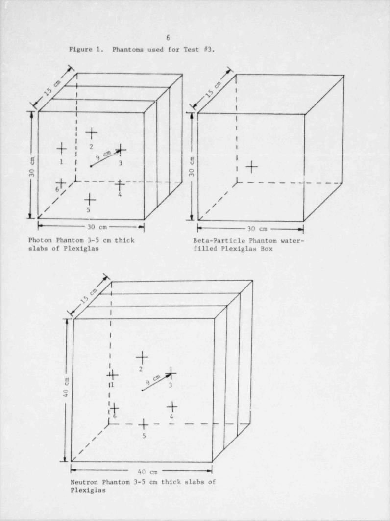
The phantoms used for photon irradiations consisted of three slabs ofPlexiglas from Rohm-lians each having dimensions of 30 cm by 30 cm by 5 cmthick. The three slabs were joined by plastic trended rods for total phantomdimensions of 30 cm by 30 cm by 15 cm thick. The neutron phantom wassimilarly constructed, using 40 cm by 40 cm by 5 cm thick slabs, for totalphantom dimensions of 40 cm by 40 cm by 15 cm thick. The phanton used forirradiations to strontium / yttrium-90 was a 30 cm by 30 cm by 15 cm thickwater filled phantom which had been used for this source during Test #1 andTest # 2. Aluminum stands were constructed having a 30 cm by 15 cm (or 40cm by 15 cm) Plexiglas platform on which the phantom was positioned.
Phantoms used for irradiations to photons and neutrons had six irradiationpositions identified at 600 intervals on a 9 cm radius circle about the centerof the front face of the phantom. The phantoms were positioned in front ofeach source by measuring the exposure rate at each of the six phantompositions, and adjusting the phantom so that the exposure rates at each of thesix positions agreed to within +1% of the average of the six exposure rates.
Because of the nature of our strontium / yttrium-90 source, only onedosimeter could be irradiated at a time. This is discussed further in sectionIll.D, and in Recommendation number 3.
Figure I shows the 3 types of phantoms used for Test #3. The phantomfor each source was positioned by distance measurements from the source,floor, and surrounding walls to the phantom. A phantom positioning diagramfor each radiation source is included in section 111 as the particular source isdiscussed.
6
Figure 1. Phantoms used for Test #3.
O etO/ i / '
/@ |</ | /,r . ,o
Ii4 Ii| 1
'
42 i--
N 1 l 3 0' 'a a
}- - - - :_- - - ----- }- - - -- - - . ' - - - -| // 5 / /
JL/ / JL /
h 30 cm d h 30 cm yPhoton Phantom 3-5 cm thick Beta-Particle Phantom water-elabs of Plexiglas filled Plexiglas Box
$0/ /,
/ \ /,r /I
I
II
| |'
I
Y ~
cta0 11 9 3
a 1
'-{- i,__
)_64
. -- - - -- - - --
/' /n
L lr 40 cm =i
Neutron Phantom 3-5 cm thick slabs ofPlexiglas
_. .- . . - _ _ __ - _ - __
7
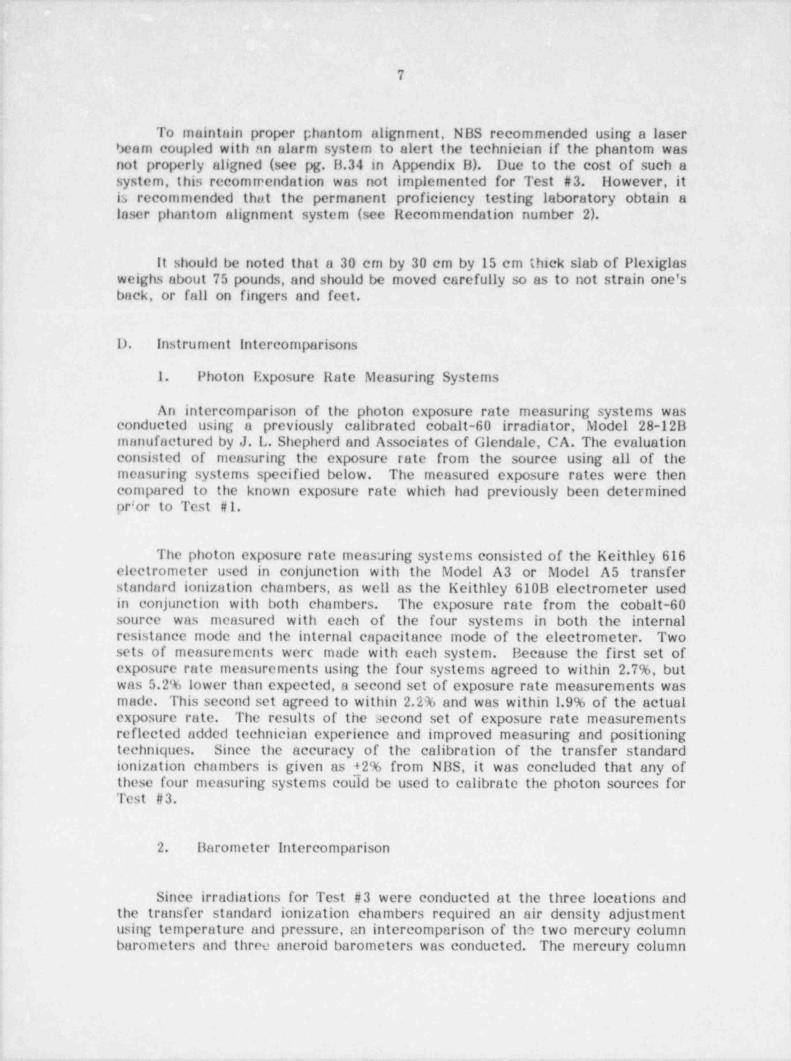
To maintain proper phantom alignment, NBS recommended using a laserScam coupled with an alarm system to alert the technician if the phantom wasnot properly aligned (see pg. B.34 in Appendix B). Due to the cost of such asystem, this recommendation was not implemented for Test #3. However, itis recommended that the permanent proficiency testing laboratory obtain alaser phantom alignment system (see Recommendation number 2).
It should be noted that a 30 cm by 30 cm by 15 cm thick slab of Plexiglasweighs about 75 pounds, and should be moved carefully so as to not strain one'sback, or fall on fingers and feet.
D. Instrument Intercomparisons
1. Photon I?xposure Rate Measuring Systems"
An intercomparison of the photon exposure rate measuring systems wasconducted using a previously calibrated cobalt-60 irradiator, Model 28-12Bmanufactured by J. L. Shepherd and Associates of Glendale, CA. The evaluationconsisted of measuring the exposure rate from the source using all of themeasuring systems specified below. The measured exposure rates were thencompared to the known exposure rate which had previously been determinedprior to Test #1.
4
The photon exposure rate measuring systems consisted of the Keithley 616electrometer used in conjunction with the Model A3 or Model A5 transferstandard ionization chambers, as well as the Keithley 610B clectrometer usedin conjunction with both chambers. The exposure rate from the cobalt-60source was measured with each of the four systems in both the internalresistance mode and the internal capacitance mode of the electrometer. Twosets of measurements werc made with each system. Because the first set ofexposure rate measurements using the four systems agreed to within 2.7%, butwas 5.2% lower than expected, a second set of exposure rate measurements wasmade. This second set agreed to within 2.2% and was within 1.9% of the actualexposure rate. The results of the second set of exposure rate measurementsreflected added technician experience and improved measuring and positioningtechniques. Since the accuracy of the calibration of the transfer standardionization chambers is given as +2% from NBS, it was concluded that any ofthese four measuring systems could be used to calibrate the photon sources for,
Test #3.
2. Barometer Intercomparison
Since irradiations for Test #3 were conducted at the three locations and,
the transfer standard ionization chambers required an air density adjustmentusing temperature and pressure, an intercomparison of the two mercury columnbarometers and three ancroid barometers was conducted. The mercury column |
_ _
8
barometer M1 located in the School of Public Health II (SPH II) was selectedas the reference barometer. The other four barometers were observed for oneweek and compared to M1. Aneroid barometer Al was adjusted to correspondto M1 and taken to the ecsium-137 irradiation facility at Willow Run severalrniles away to compare to A3. Ar.eroid barometer A2 agreed with M1 to within0.5 E The mercury column M2 agreed with M1 to within 1% Barometer A3agreed with Al to within 1.25 Barometer Al was left at Willow Run andused for the calibration of the two photon sources at that facility.
:
|
|
__ _
. _
!
8i
|- Ill. RADIATION SOURCES s
A. . General
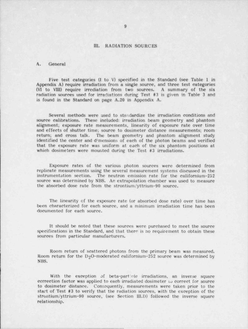
Five test categories (I to V) specified in the Standard (see Table 1 ini Appendix A) require irradiation from a single source, and three test categories
(VI to Vill) require irrediation from two sources. A summary of the six -radiation sources used for irradiations during Test #3 is given in Table 3 andis found in the Standard on page A.20 in Appendix A.
Several methods were used to standardize the irradiation conditions andsource calibrations. These included: irradiation beam geometry and phantomalignment; exposure rate measurements, linearity of exposure rate over timeand effects of shutter time; source to dosimeter distance measurements; roomreturn; and cross talk. The beam geometry and phantom alignment studyidentified the center and d!mensions of each of the photon beams and verifiedthat the exposure rate was uniform at each of the six phantom positions atwhich dosimeters were mounted during the Test #3 irradiations.
Exposure rates of the various photon sources were determined fromreplicate measurements using the several measurement systems discussed in theinstrumentution section. The neutron emission rate for the californium-252source was determined by NBS. An extrapolation chamber was used to measurethe absorbed dose rate from the strontium / yttrium-90 sourec.
The linearity of the exposure rate (or absorbed dose rate) over time hasbeen characterized for each source, and a minimum irradiation time has beendocumented for each source.
It should be noted that these sources were purchased to meet the sourcespecifications in the Standard, and that there is no requirement to obtain thesesources from particular manufacturers.
Room return of scattered photons from the-primary beam was measured.Room return for the D 0-moderated californium-252 source was determined by2N BS.
With the exception af beta-particle irradiations, an inverse squarecorrection factor was applied to each irradiated dosimeter ta correct for sourceto dosimeter distance. Consequently, measurements were taken prior to thestart of Test #3 to verify that the radiation sources, with the exception of thestrontium / yttrium-90 source, (see Section Ill.D) followed the inverse squarerelationship.
.- _- - -
_ ____ __ _ - . . ___
,
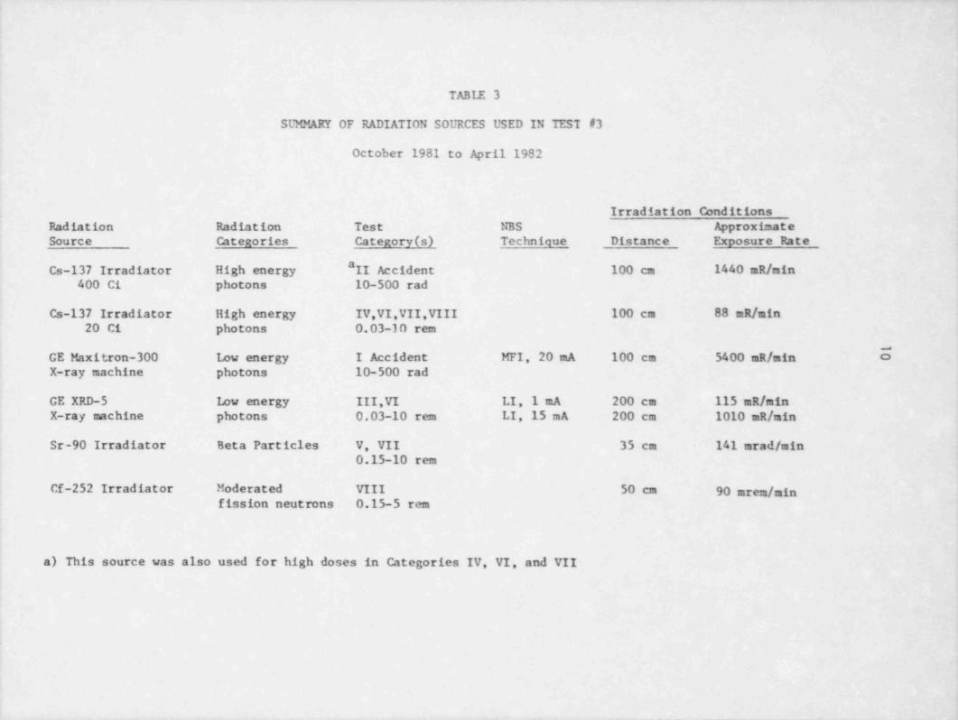
TABLE 3
SUMMARY OF RADIATION SOURCES USED IN TESI #3
October 1981 to April 1982
Irradiation Conditions,*
Radiation Radiation Test NBS ApproximateSource Categories Category (s) Technique Distance Exposure Rate
aCs-137 Irradiator High energy II Accident 100 cm 1440 mR/ min
400 Ci photons 10-500 rad
Cs-137 Irradiator High energy IV,VI,VII,VIII 100 cm 88 mR/ min20 Ci photons 0.03-10 rem
GE Maxitron-300 Low energy I Accident MFI,- 20 mA 100 cm 5400 mR/ min 5X-ray machine photons 10-500 rad
GE XRD-5 kw energy III,VI LI, 1 mA 200 cm 115 mR/ minX-ray machine photons 0.03-10 rem LI,15 mA 200 cm 1010 mR/ min
Sr-90 Irradiator Beta Particles V, VII 35 cm 141 mrad / min0.15-10 rem
Cf-252 Irradiator Moderated VIII 50 cm 90 mrem / minfission neutrons 0.15-5 rem
a) This source was also used for high doses in Categories IV, VI, and VII
- _ _ _ _ _ - _ _ - _ _ _ _ _ _ _ _ _
~
11
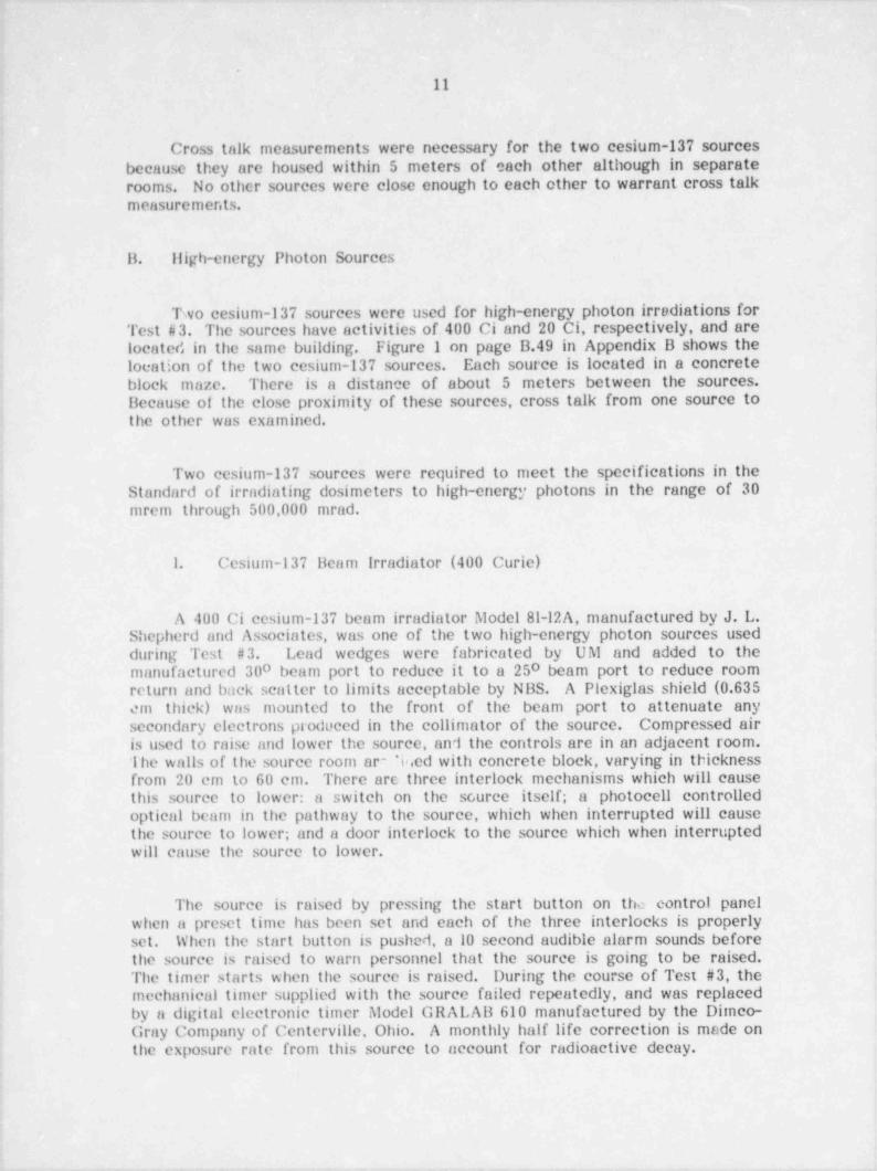
Cross talk measurements were necessary for the two cesium-137 sourcesbecause they are housed within 5 meters of each other although in separaterooms. No other sources were close enough to each other to warrant cross talkmeasurements.
B. liigh-energy Photon Sources
Two cesium-137 sources were used for high-energy photon irradiations for'
Test #3. The sources have activities of 400 Ci and 20 Ci, respectively, and are |
located in the same building. Figure 1 on page B.49 in Appendix B shows the (location of the two cesium-137 sources. Each source is located in a concrete
I block maze. There is a distance of about 5 meters between the sources.Because of the close proximity of these sources, cross talk from one source to,
4 the other was examined.
Two ecsium-137 sources were required to meet the specifications in theStandard of irradiating dosimeters to high-energy photons in the range of 30mrem through 500,000 mrad.
! 1. Cesium-137 Beam Irradiator (400 Curie)!
A 400 Ci cesium-137 beam irradiator Model 81-12A, manufactured by J. L.,
1 Shepherd and Associates, was one of the two high-energy photon sources usedJ during Test # 3. Lead wedges were fabricated by UM and added to the! manufactured 300 beam port to reduce it to a 250 beam port to reduce room
return and back scatter to limits acceptable by NBS. A Plexiglas shield (0.635em thick) was mounted to the front of the beam port to attenuate anysecondary electrons produced in the collimator of the source. Compressed airis used to raise and lower the source, and the controls are in an adjacent room.'lhe walls of the source room ar" *ir.ed with concrete block, varying in thicknessfrom 20 cm to 60 cm. There are three interlock mechanisms which will cause
| this source to lower: a switch on the scurce itself; a photocell controlledoptical beam in the pathway to the source, which when interrupted will causethe source to lower; and a door interlock to the source which when interruptedwill cause the source to lower.
The source is raised by pressing the start button on the control panelwhen a preset time has been set and each of the three interlocks is properlyset. When the start button is pushed, a 10 second audible alarm sounds beforethe source is raised to warn personnel that the source is going to be raised.The timer starts when the source is raised. During the course of Test #3, themechanical timer supplied with the source failed repeatedly, and was replacedby a digital electronic timer Model GRALAB 610 manufactured by the Dimco-Gray Company of Centerville, Ohio. A monthly half life correction is made on
,
the exposure rate from this source to account for radioactive decay.'
r
- - - .~ _ - - . - - _ . . _
-. . - - - .
.
12
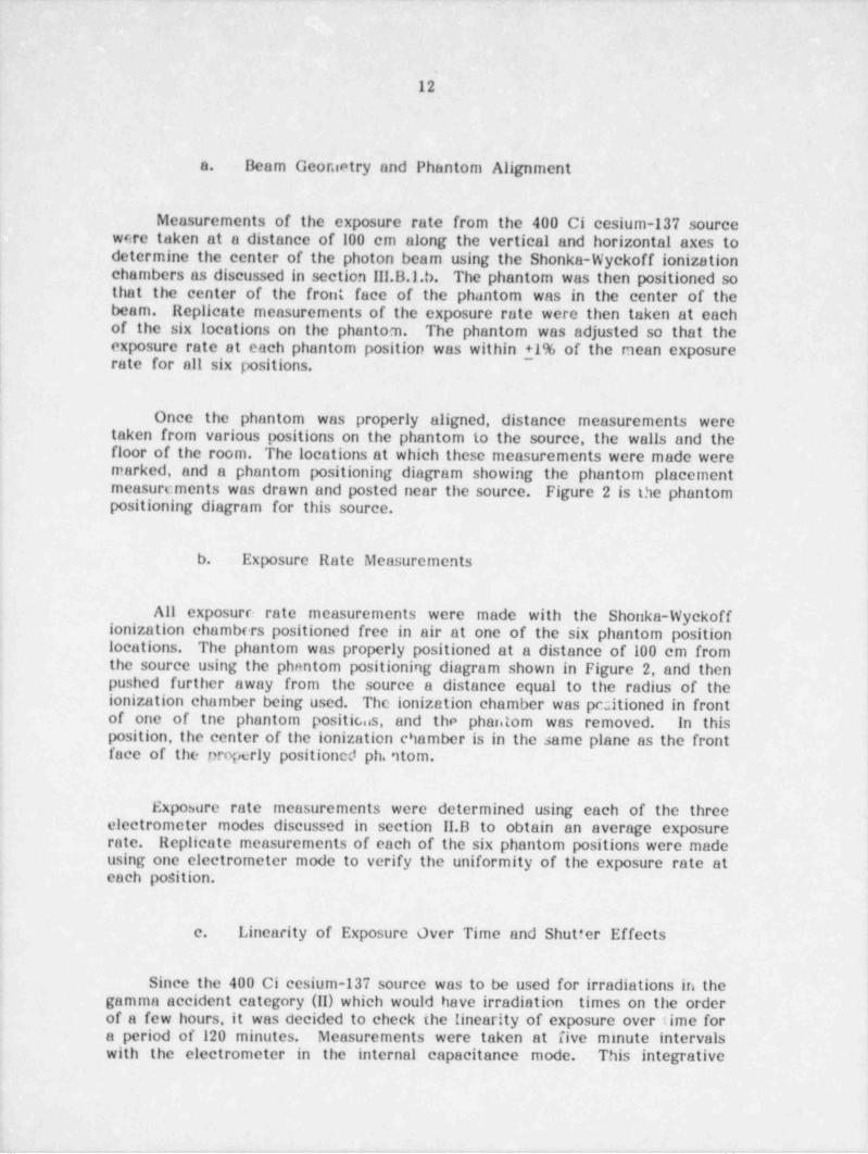
Beam Geor.ietry and Phantom Alignmenta.
Measurements of the exposure rate from the 400 Ci cesium-137 sourcei w<!re taken at a. distance of 100 cm along the vertical and horizontal axes to
determine the center of the photon beam using the Shonka-Wyckoff ionization;'
chambers as discussed in section III.B.I.b. The phantom was then positioned sothat the center of the front' face of the phantom was in the center of the
' beam. Replicate measurements of the exposure rate were then taken at'eachof the six locations on the phantom. The phantom was adjusted so that the ,
exposure rate at each phantom position was within +1% of the mean exposurerate for all six positions.
1
(
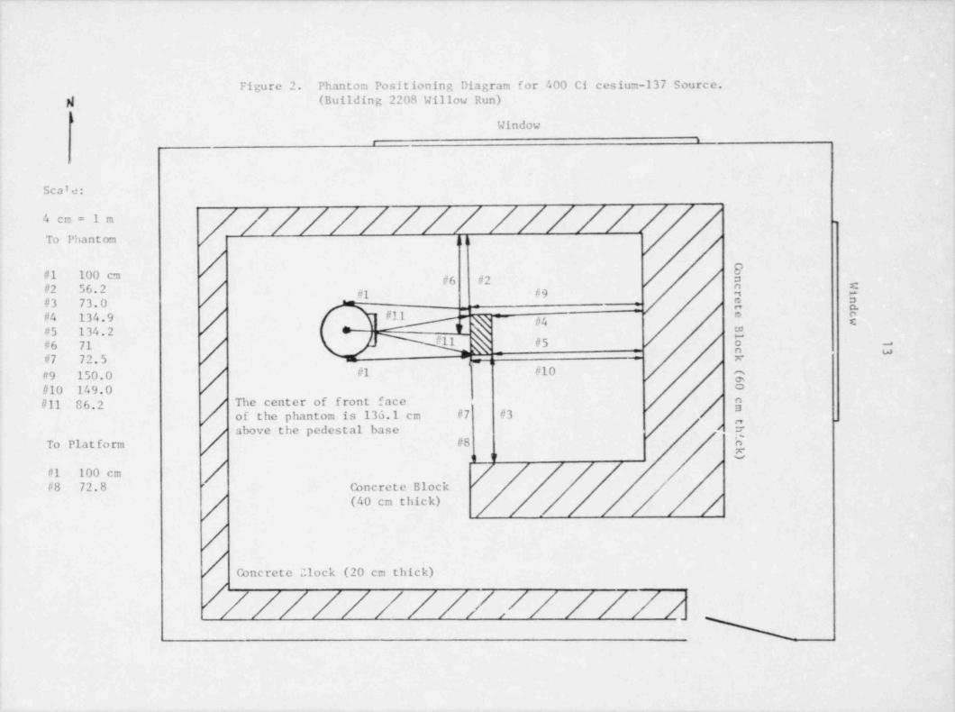
Once the phantom was properly aligned, distance measurements weretaken from various positions on the phantom to the source, the walls and thefloor of the room. The locations at which these measurements were made weremarked, and a phantom positioning diagram showing the phantom placement,
measurements was drawn and posted near the source. Figure 2 is the phantompositioning diagram for this source.
b. Exposure Rate Measurements
All exposurr: rate measurements were made with the Shonka-Wyckoffionization chambers positioned free in air at one of the six phantom position
r locations. The phantom was properly positioned at a distance of 100 cm fromthe source using the phantom positioning diagram shown in Figure 2, and then
i pushed further away from the source a distance equal to the radius of theionization chamber being used. The ionization chamber was pcsitioned in frontof one of the phantom positic..s, and the phantom was removed. In thisposition, the center of the ionization chamber is in the same plane as the frontface of the properly positioned ph. 'itom.
.
1
Exposure rate measurements were determined using each of the threeelectrometer modes discussed in section II.B to obtain an average exposurerate. Replicate measurements of each of the six phantom positions were madeusing one electrometer mode to verify the uniformity of the exposure rate ateach position.,
c. Linearity of Exposure Over Time and Shutter Effects|
Since the 400 Ci cesium-137 source was to be used for irradiations in thegamma accident category (II) which would have irradiation times on the orderof a few hours, it was decided to check the linearity of exposure over time for
; a period of 120 minutes. Measurements were taken at five minute intervalswith the electrometer in the internal capacitance mode. This integrative,
i
_ _ _ ,_ ._ . .-- _ _ - , . . . _ , _ _ . . . _ - _
_ _ _ _ _ _ _ _ _ _ _ _ _ _ _ _ - _ - _ _ _ - - _ - _ _ _ _ - _ - _ _ - - _ __ - -___ -___ - ________ - ___ _ _- _ _ __ __ _ -- - _______ _ - - _-___ _ ___-_ _
Figure 2. Phantom Positioning Diagram for 400 Ci cesium-137 Source.N (Building 2208 Willow Run)
Window-
.
Scale:
///////// //////'- " -
To Phantom I h
9#1 100 cm #6 #2#2 56.2 / -g g9
c
#3 73.0 / _
- e :s
#'t/5 1 4. O - t
~
7 .5 ,
ft9 150.0 / #1 #10 m
$#10 149.0 /#11 86.2 / The center of front face / n
a[ of the phantom is 136.1 cm #7 #3 /
Eabove the pedestal base /
/ #8To Platform
#1 100 cmConcrete Block /#8 72.8 '
(40 cm thick)
/Concretc 21ock (20 cm thick)
//////////// //// N
.- - - - -
- - . - - . . .. - _ - . -
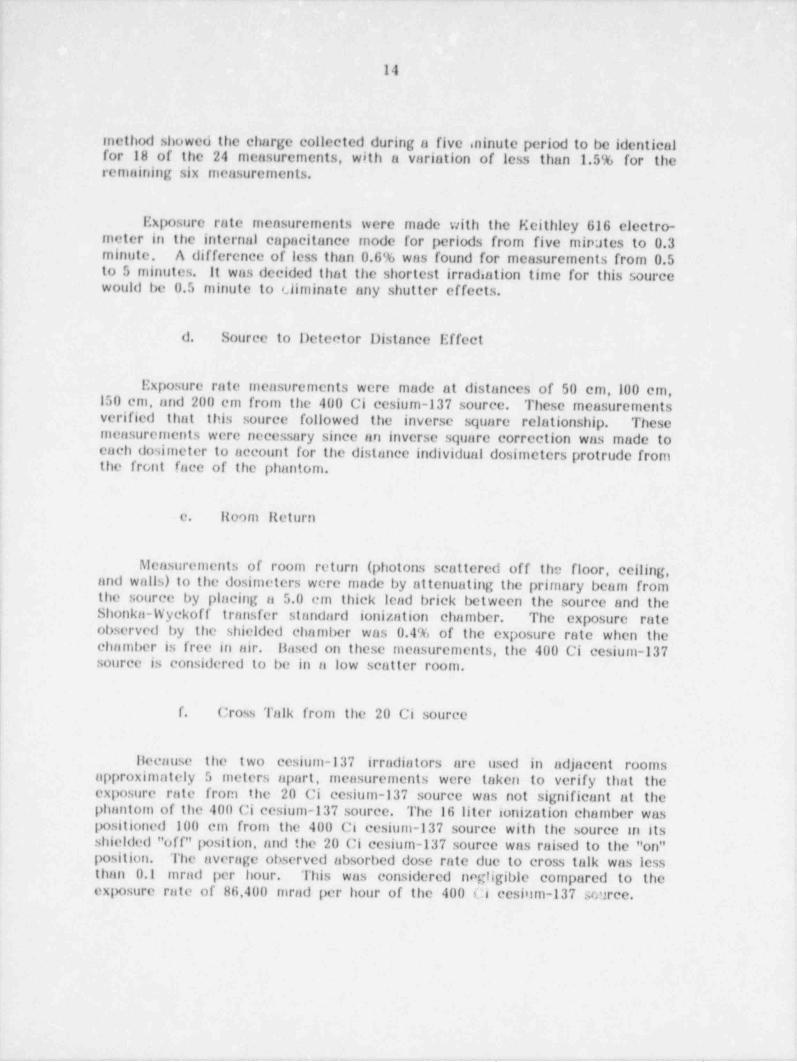
141
method showed the charge collected during a five ininute period to be identical |2
for 18 of the 24 measurements, with a variation of less than 1.5% for theremaining six measurements.
!
Exposure rate measurements were made with the Keithley 616 electro- .
meter in the internal capacitance mode for periods from five mirrates to 0.3 |minute. A difference of less than 0.6% was found for measurements from 0.54
to 5 minutes, it was decided that the shortest irradiation time for this source'
would be 0.5 minute to climinate any shutter effects.4
d. Source to Detector Distance Effect
Exposure rate measurements were made at distances of 50 cm,100 cm,150 cm, and 200 cm from the 400 Ci cesium-137 source. These measurementsverified that this source followed the inverse square relationship. These t
measurements were necessary since an inverse square correction was made to'
cach dosimeter to account for the distance individual dosimeters protrude fromthe front face of the phantom.
!
| c. Itoom fleturnI
Measurements of room return (photons scattered off the floor, ceiling,i and walls) to the dosimeters were made by attenuating the primary beam from. the source by placing a 5.0 cm thick lead brick between the source and the! Shonka-Wyckoff transfer standard ionization chamber. The exposure rate'
observed by the shielded chamber was 0.4% of the exposure rate when thechamber is free in air. Itased on these measurements, the 400 Ci cesium-137source is considered to be in a low scatter room.
f. Cross Talk from the 20 Ci source
llocause the two cesium-137 irradiators are used in adjacent roomsapproximately 5 meters apart, measurements were taken to verify that theexposure rate from the 20 Ci ecsium-137 source was not significant at thephantom of the 400 Ci cesium-137 source. The 16 liter ionization chamber waspositioned 100 cm from the 400 Ci cesium-137 source with the source m itsshielded "off" position, and the 20 Ci cesium-137 source was raised to the "on"position. The average observed absorbed dose rate due to cross talk was lessthan 0.1 mrad per hour. This was considered negligible compared to the
,
exix>sure rate of 86,400 mrad per hour of the 400 Ci cesium-137 source.
- -- - . , _ - - - - .. . --- - . . _ . - - . . . , -. - -_---
._ - - - - _- .. __. . .
15
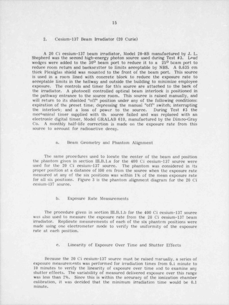
2. Cesium-137 Beam Irradiator (20 Curie)
A 20 Ci cesium-137 beam irradiator, Model 28-8B manufactured bShepherd was the second high-energy photon source used during Test #3.y J. L.Leadwedges were added to' the 300 beam port to reduce it to a 250 beam port toreduce room return and backscatter to limits acceptable by NBS. A 0.635 cmthick Plexiglas shield was mounted to the front of the beam port. This source
| Is used in a room lined with concrete block to reduce the exposure rate toacceptable limits in the hallway and outside the building to minimize employeeexposure. The controls and timer for th!s source are attached to the back ofthe irradiator. A photocell controlled optical beam interlock is positioned inthe pathway entrance to the source room. This source is raised manually, andwill return to its shielded "off" position under any of the following conditions:expiration of the preset time; depressing the manual "off" switch; interruptingthe interlock; and a loss of power to the source. During Test #3 the
j meebanical timer supplied with the source failed and was replaced with anelectronic digital timer, Model GRALAB 610, manufactured by the Dimeo-Gray
i Co. A monthly half-life correction is made on the exposure rate from this' source to account for radioactive decay.
,
j a. Beam Geometry and Phantom Alignmenta
The same procedures used to locate the center of the beam and positioni the phantom given in section Ill.B.I.a for.the 400 Ci cesium-137 source were
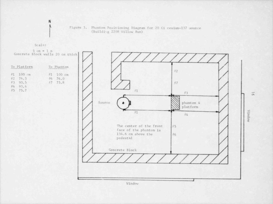
used for the 20 Ci cesium-137 source. The phantom was considered in itsproper position at a distance of 100 cm from the source when the exposure ratemeasured at any of the six positions was within 1% of the mean exposure ratefor all six positions. Figure 3 is the phantom alignment diagram for the 20 Cicesium-137 source.
;
I
b. Exposure Rate Measurements
The procedure given in section Ill.B.I.b for the 400 Ci cesium-137 sourcewas also used to measure the exposure rate from the 20 Ci cesium-137 beam,
irradiator. Replicate measurements of each of the six phantom positions were,
| made using one electrometer mode to verify the uniformity of the exposurerate at each position.
,
c. Linearity of Exposure Over Time and Shutter Effects
,
Because the 20 Ci cesium-137 source must be raised marually, a series of,
j exposure measurements was performed for irradiation times from 0.1 minute to10 minutes to verify the linearity of exposure over time and to examine anyshutter effects. The variability of measured delivered exposure over this range
1 was less than 2% Since this is within the accuracy of the ionization chamber! calibration, it was decided that the minimum irradiation time would be 0.1
minute.
__. ._ _ _____ _ _ _ _ . .. ____ _ . _ __. . _ _ _ . _ __- - _ _ _ _ .
. _ _ _ _ _ _ _ _ _ _ _ _ _ _ _ _ _ _ - - . -
N
j k Figure 3. Phantom Positioning Diagram for 20 Ci cesium-137 source(Buildi'.g 2208 Willow Run)
Scale:
5 cm = 1 mConcrete Block walls 20 cm thick
To Plat form To Phantom_
#1 100 cm #1 100 cm /#2 74.3 #6 76.0 /#4 9 4#5 75.7 #1
#3 -m ,
Source e phantom &platform
-
- s:
/ py ,-
#4 o
/ The center of the front #5 /face of the phantom is [/ 134.6 cm above the #6pedestal
/,///// /// //////. _ . 1.c. .
,
I
| Window
- _ _ _ _ _ _ - - _ _ _ _
17
d. Source to Detector Distance Effect!
Exposure rate measurements were made at distances of 50 cm,100 cm,and 150 cm from the 20 Ci cesium-137 source to verify that the inverse square
l relationship applied.
c. Itoom Iteturn
As described in section III.B.1.c for the 400 Ci cesium-137 source,measurements were made in the 20 Ci cesium-137 source room with theionization chamber shielded by a 5.0 cm thick lead brick. It was found thatthe room return was less than 1% of the primary beam exposure rate, whichwas acceptable to NBS.
f. Cross Talk from the 400 Ci Source
Measurements of cross talk from the 400 Ci cesium-137 source in the 20Ci cesium-137 source room were conducted with the 16 liter ionization chamberpositioned at a distance of 100 cm from the 20 Ci source. With this sourcein the "off" position, the 400 Ci source was raised to the "on" position. Theobserved absorbed dose rate due to cross talk was found to be 0.7 mrad /h. Thisis 0.1% of the primary exposure rate from the 20 Ci source, and is consideredto be negligible.
C. Low-energy Photon Sources
Two X-ray machines were used during Test #3 for low-energy photoairradiations. Thesc X-ray machines are a General Electric Maxitron 300 and aGeneral Electric XIID-5. Table 1 of the Standard (pg. A.20 in Appendix A ofthis report) specifies six NBS X-ray techniques (specific combinations of X-raytube potential and filtration) from which the testing laboratory can choose forirradiations in categories 111 and VI. One of the six NBS X-ray techniques, MFI,is also specified in Table 1 of the Standard to be used for the X-ray accidentirradiations for Category I. Table 2 of the Standard (pg. A.21 in Appendix Aof this report) gives the X-ray beam qualitias of these techniques. I
Two X-ray machines were required because the maximum potential of the !
XILD-5 is 60 kVp (the minimum is 5 kVp) and the minimum potential for the |Maxitron 300 is 75 kVp (the maximum is 300 kVp). The proficiency testinglaboratory would only need one X-ray machine if all the NBS X-ray techniquesspecified in the Standard could be used with the machine.
- _ _ _ _ _ _ - _ . _ _ _ _ _ _ _
18
1. Maxitron 300 X-ray Machine
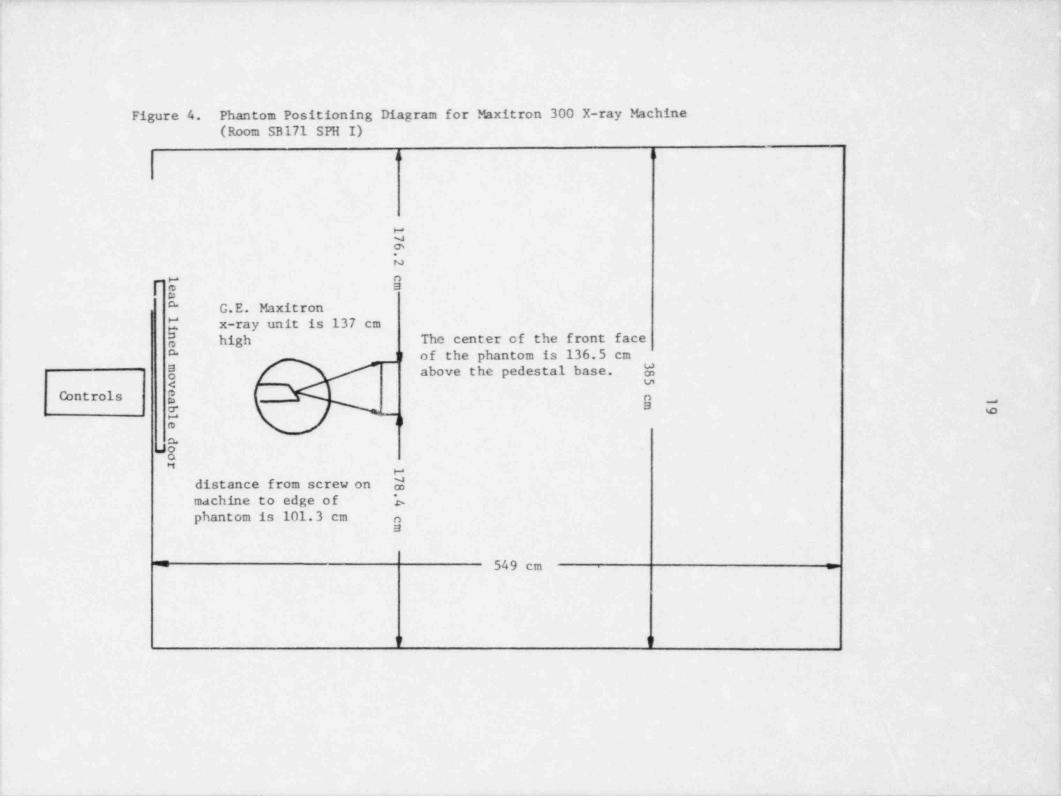
A General Electric Maxitron 300 therapeutic X-ray machine was used forirradiations in Category 1 (X-ray accident). This is the same X-ray machineused for Tests #1 and #2. This X-ray machine has an inherent filtration of 4.75mm Be. Two timers are used to time all irradiations. Room return for theMaxitron 300 has been found to be less than 1% of the primary beam which isaceptable to NBS. Prior to the start of Test #3, the exposure rate from NBSX-ray technique MF1 was measured free in air with the transfer standardionization chambers for all six phantom positions to verify that the exposurerate at an individual position was within 1% of the mean of the exposure rateat all six positions. Figure 4 is tne phantom positioning diagram for theMaxitron 300. Irradiations from the Maxitron 300 X-ray machine wereconducted with the phantom positioned at 100 cm from the source. This sourcehas been shown to follow the inverse square relationship at distances greaterthan 20 cm. Exposure measurements over time indicate the stability of the X-ray beam, and indicate that the minimum irradiation time for this source is 1.0minute.
For Test #3, two changes were made in the procedures used during Tcst#1 and #2 to irradiate dosimeters to X-rays. First, each time the X-ray
machine was used, the first and second half-value layers, ilVLi and ilVL .2respectively, were measured, and the homogeniety coefficient, h = IlVL /IIVL .1 2was computed. The kilovoltage or filtration was adjusted so that IIVL1 waswithin +5% and h was within +10% of the NBS reference value. An X-rayspectruih sheet (see pg. C.15) was used to document the X-ray beamcharacteristics each time the X-ray machine was used. Prior to the beginningof Test #3, the NBS X-ray technique MF1 was set up several times. As a resultof this experience, a packet of filters was made and used each time MFI wasset up. Usually, only a minor adjustment in the tube potential was required toproduce an MFI spectrum which was acceptable. Once the X-ray technique wasconsidered neceptable, an initial exposure rate was measured as described insection Ill.B.I.b for the 400 Ci cesium-137 scurce. Irradiation times werecalculated using this exposure rate, and the dosimeters were irradiated.Following irradiation of the dosimeters, the exposure rate was measured again.If the final exposure rate at the end of the day differed from the exposure rateat the beginning of the day by more than 2%, the irradiations for the day wereto be voided. During the course of Test #3, the initial and final exposure ratesalways agreed to within 1.5%, and no dosimeters were voided. The average ofthe initial and final exposure rates was recorded on the data sheets and usedto calculate the delivered dose equivalent to each dosimeter.
A second change in X-ray irradiation procedures from Tests #1 and #2 toTest #3 was the type of X-ray beam monitor used. For Test #3, after the X-ray technique was established and the initial exposure rate obtained, thephantom was placed on its stand, and the transfer-standard ionization chamberwas positioned to the side of the phantom in the same plane as the calibration.A strip chart recorder was connected to the electrometer to monitor the X-rayintensity during the course of irradiations.
_ _ _ -___ _ _ _ _ _ _ _ _ _ _ _ _ _ _ _ _ _ _ .
,
Figure 4. Phantom Positioning Diagram for Maxitron 300 X-ray Machine(Room SB171 SPH I)
a h
C.
N
FE OmA" G.E. Maxitron
{ x-ray unit is 137 cmhigh The center of the front faceo
J l of the phantom is 136.5 cm"
8 / above the pedestal base. M< s.n
Controls i g'r 7
.53 -
distance from screw on Mmachine to edge of bphantom is 101.3 cm n
9
= 549 cm =
U U
1
_ _ . _ . _ _ _ _ _ _ . _ _ _ _ _ _ _ _ _ _ _ . . _ _ _ _ _ _ _ _ . _ _ .
20
2. XRD-5 X-ray Machine
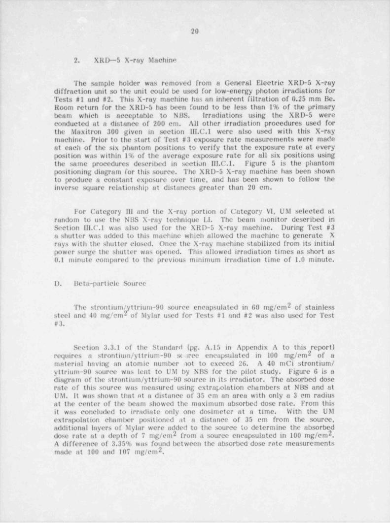
The sample holder was removed from a General Electric XRD-5 X-raydiffraction unit so the unit could be used for low-energy photon irradiations forTests #1 and #2. This X-ray machine has an inherent filtration of 0.25 mm Be.Room return for the XRD-5 has been found to be less than 1% of the primarybeam which is acceptable to N BS. Irradiations using the XRD-5 wereconducted at a distance of 200 cm. All other irradiation procedures used forthe Maxitron 300 given in section III.C.1 were also used with this X-raymachine. Prior to the start of Test #3 exposure rate measurements were madeat each of the six phantom positions to verify that the exposure rate at everyposition was within 1% of the average exposure rate for all six positions usingthe same procedures described in section III.C.1. Figure 5 is the phantompositioning diagram for this source. The XRD-5 X-ray machine has been shownto produce a constant exposure over time, and has been shown to follow theinverse square relationship at distances greater than 20 cm.
For Category 111 and the X-ray portion of Category VI, UM selected atrandom to use the NBS X-ray technique LI. The beam monitor described inSection lif.C.1 was also used for the XRD-5 X-ray machine. During Test #3a shutter was added to this machine which allowed the machine to generate Xrays with the shutter closed. Once the X-ray machine stabilized from its initialpower surge the shutter was opened. This allowed irradiation times as short as0.1 minute compared to the previous minimum irradiation time of 1.0 minute.
D. Beta-particle Source|
2 of stainlessThe strontium / yttrium-90 source encapsulated in 60 mg/cmsteel and 40 mg/cm2 of Mylar used for Tests #1 and #2 was also used for Test# 3.
i|
Section 3.3.1 of the Standard (pg. A.15 in Appendix A to this report)2 of arequires a strontium / yttrium-90 su rce encapsulated in 10 0 mg/cm
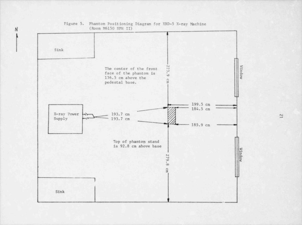
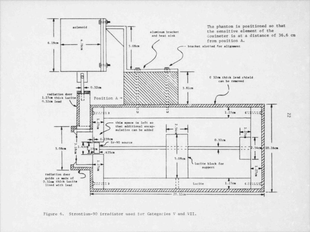
material having an atomic number got to execed 26. A 40 mci strontium /yttrium-90 source was lent to UM by NBS for the pilot study. Figure 6 is adiagram of the strontium / yttrium-90 source in its irradiator. The absorbed doserate of this source was measured using extrapolation chambers at NBS and atUM. It was shown that at a distance of 35 cm an area with only a 3 cm radiusat the center of the beam showed the maximum absorbed dose rate. From thisit was concluded to irradiate only one dosimeter at a time. With the UMextrapolation chamber positioned at a distance of 35 em from the source,additional layers of Mylar were added to the source to determine the absorbed
2dose rate at a depth of 7 mg/cm2 from a source encapsulated in 100 mg/cm ,A difference of 3.35% was found between the absorbed dose rate measurements
2made at 100 and 107 mg/cm ,
--
._ _ _ _ _ _ -_ _ _ . _ _ . _ _. _ _ _ . _ . _ _ _ _ _ . _ _ _ _ _ _ _ . _. _. _ _ ._. _ _ _ .
Figure 5. Phantom Positioning Diagram for XRD-5 X-ray Machineg (Room M6150 SPH II)
|l(
Sink
.
N =cThe center of the front N yface of the phantom is ,- g-136.5 cm above the Cnpedestal base. 5
..
199.5 cm r= 184.5 cm =
X-ray Power % 193.7 cm-
3Supply % 193.7 cm__
,l 185.9 cmu =
.
Top of phantom standis 92.8 cm above base
' $a.~
E. E
9
M
Sink
V .
___-__-_____-_ - _ _ -. _ - _ _ _ _ . ._
" [spsolenoid The phantom is positioned so that
haluminum bracket the sensitive element of theand heat sink dosimeter is at a distance of 36.6 cm
_
from position A.6.19cm _ {'
5.08cm - bracket slotted for alignment'
{
'
q,l rm, rm,
0 32cm thick lead chield_ ,,,,, can be removed
-> e- 0.32cm 3.81cmj
radiation door - e''j Position A +1.27cm thick Lucite
t h _,j'O.32cm lead
)/mmmmm////fr/w////////(1///////> //////////////////////////////O7 th
|-----'.. .. A *
,..-du u 1.27cm c::. :;3 yT / N
h"
4L> this space is left so /E that additional encap- F /
I6. sulation can be added "*""" [ * [, f"
Y X /*
H + /i>-, 0.159cm 0.32cm l- /i
=- Sr-90 source gI 222 222 -;; 2.54cu/ 10.16cm5.08cm %* 27:n
S I . _* .635cm i j5.0Pcm l f
'
3,-g :L. Lucite block for %
rf/f//f//ff { support ,e " q1'
/ M /,radiation door @ pf 3,
guide is made of /,, g0.32cm thick tacite s . .. ee #
.3 i 1. 27m c ' '- ~- ~slined with lead e---"- 8' M9////// ////////// ///////////// //////// /////////// // /// / ///////////// //b 1
'
| 20.32cm n',
t
!
Figure 6. Strontium-90 irradiator used for Categories V and VII.
_ _ _ _ _ _ _ _ _
!
! 23!
The irradiation procedure for Test #3 was changed from that used forTests #1 and #2. For the earlier tests, the phantom was positioned at adistance of 35 cm from the source and the delivered dose equivalent was to the
, front face of the phantom. For Test #3, the distance cach dosimeter protruded| from the front face of the phantom was measured, and the phantom was moved
away from the source that distance, so that the sensitive element of the'
dosimeter was at a distence of 35 cm from the source. This was done becausebeta particles do not follow inverse square. Only one dosimeter at a time wasirradiated with this source because of the collimating effect of the source.Prior to the start of Test #3, the calibration of this source was checked using
j the UM extrapolation chamber which had previously been intercompared with| the extrapolation chamber at NBS. The source calibration agreed to within1 2.0% of the half-life corrected absorbed dose rate. A monthly half-life
correction was performed on the absorbed dose rate from this source toaccount for radioactive decay.
E. D 0-moderated Californium-252 Source2
One of the modifications in the Standard after Tests #1 and #2 was tochange the neutron source from a bare californium-252 source to a D 0-
2moderated californium-252 sourec. This source is moderated by a stainlesssteel sphere 15 cm in radius which is wrapped with a cadmium shell and filledwith D 0. The spectrum of this source contains lower energy neutrons than2those found in the bare californium-252 spectrum. Documentation of the designand use of this source is available from NUllEG/ Cit-1204 prepared by Schwartz
2and Eisenhauer at NBS . The IIPSSC committee who wrote the Standerd madethis change in the Standard in an effort to obtain a neutron spectrum thatwould approximate the neutron spectra observed at nuclear power plants and toenhance the response of albedo neutron dosimeters by lowering the averageneutron energy.
This neutron source is housed in the building used for neutron irradiationsfor Tests #1 and #2 at the UM Willow flun laboratory facility. A cylindricalhole with a 122 cm diameter and 122 cm depth in the concrete floor was linedwith a fiberglass laminate mixture and filled with deionized distilled ivater.This water-filled pit was used to store the californium-252 source when it wasnot in the moderating sphere irradiating dosimeters. The apparatus used forneutron irradiations for Tests #1 and #2 was disassembled, and the D 0-filled
2<
moderating sphere was hung from the ceiling so that the center of the spherewas aligned with the center of the 40 cm by 40 cm by 15 cm thick Plexiglasphantom, 245 cm above the floor to reduce room return from neutronsscattered off the floor. Irradiations at this height are not required by theStandard. A californium-252 source, calibrated at NBS, was loaded into a D 0-
2filled stem and was stored in the water pit. Figures 3 and 4 on pages B.51 and11.52 in Appendix B to this report show the D 0-filled sphere and source2assembly, respectively. The source assembly shown on page B.52 was modifiedby attaching a 30 cm lead-filled stainless steel tube to the D 0-filled stem to
2add additional mass to the source assembly to cause the source to fall into thewater-filled pit when the cable used to raise the source was released. During
! the course of Test #3 the threaded bolt connecting the source stem and the!I1
-- - -
_ _ _ _ - _ _ _ _ _ _ _ _ _ _ _ _
24
lead stem broke, causing the californium-252 source to fall into the pit. Thisproblem was resolved by using a thicker threaded bolt to connect the sourcestem and the lead stem. This source-stem assembly was raised out of the pitand into the D 0-filled moderating sphere by means of a stainless steel cable.2
A sponge pad was placed on the bottom of the water-filled pit to cushionthe fall of the source-stem assembly if the cable broke. Under normaloperation of lowering the source, the cable was anchored to cause the source-stem to stop just prior to encountering the sponge pad.
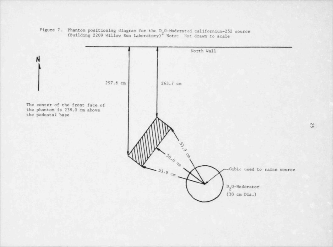
Multiple readings were made with the A-5 Shonka-Wyckoff trar.sferstandard ionization chamber at each of the six phantom positions to align thesource and the phantom. The phantom was aligned at a distance of 50 cm fromthe source to the front face of the phantom. Each of the six phantom positionsgave an ionization chamber response within 1% of the mean response of all sixpositit,as. Figure 7 is the phantom positioning diagram for this source.Measurements were also made at distances of 40 cm and 6') em to verify thatthis source followed the inverse square relationship. It was found that fordistances greater than 60 cm, room return was a problem and the source didnot follow the inverse relationship. llowever, for distances from 40 cm to 60cm the inverse square relationship holds. During the NBS site visit it wasdetermined that room return was not significant at a distance of 50 cm fromthe D 0-moderated californium-252 source.2
Irradiations were conducted using UM thermoluminescent dosimeters(TI.Ds) at the same distances at which ionization chamber measurements weremade. These TLD data showed that this source follows the inverse squarerelationship and that the phantom was properly aligned at 50 cm. An inversesquare correction was applied to the dose equivalent to each dosimeter toaccount for the distance the dosimeter protruded from the front face of thephantom.
Variation in delivering dose equivalents to test dosimeters by differenttechnicians was evaluated by two sets of measurements taken with a Shonka-Wyckoff transfer standard ionization chamber. The first set of measurementswas used to check the reproducibility of a technician in raising the source,irradiating for a given time period, and lowering the source. This set ofmeasurements was also used to check reproducibility among the technicians.For the second set of measurements, several replicate irradiations were madeby each technician. The data showed that an individual technician couldirradiate dosimeters reproducibly within 11%, and the reproducibility among the
within 12% A single technician did all of the neutrontechnicians wasirradiations for Teat #3.
Measurements were taken for irradiation times of 5 minutes, 3 minutes,2 minutes,1 minute, 45 seconds, 30 seconds, and 15 seconds to identify the
D 0-moderated californium-252 source.minimum irradiation time for the 2From these data it was concluded that the shortest irradiation time for neutronirradiations was one minute.
_ _ _ _ _ _ _ _ _ _ _ _ _ _ _ _ _ _ _ _ _ _ _ _
._ _ _ ._ _ _ _ _
Figure 7. Phantom positioning diagram for the D 0-M derated californium-252 source(Building 2209 Willow Run laboratory)2 Note: Not drawn to scale
d d l North Wall
k
297.6 cm 263.7 cm
.
The center of the front face ofthe phantom is 238.0 cm abovethe pedestal base l
'
fi k
'O'#
q ,
3 *+0*O
%3 Cabic used to raise source
cm%D 0-Moderator
2
(30 cm Dia.)
_ _ _ _ _ _ _ _ _ _ _ _ _ _ _ _ _ _ _ _ _ _ _ _ _ _ _ _ _ .
. __ . _ __ _ _ _ _ . . . . __
2G
The D 0-moderated californium-252 source was calibrated at NBS. A2
listing of daily neutron emission rates was sent to UM from NDS. These
! cmission rates reflect a daily half-life correction to account for radioactivedecay. The emission rates were used to calculate neutron dose equivalent rates'
,as described in section IV of this report. A discussion of the photoncontribution from the D 0-moderated californium-252 source is also given in! 2
]section IV of this report.
It should be noted that there was some controversy over the photoncontribution to the dose equivalent from the neutron source. Measurementsmade at the UM indicate that the ratio of photon to neutron dose equivalentrates from the D 0-moderated californium-252 source is 0.18 instead of 0.302as previously assumed.3
1
The D 0-moderated californium-252 source posed a problem which the2
other radiation sources did not. Because of the high neutron emission rate ofthe source which is needed to obtain a reasonable dose equivalent rate through15 cm of D 0, the source had to be shipped in a special " cannon ball" shipping t
2cask. The source had to be removed from the shipping cask using a remotemanipulator and placed in the water-filled pit, unlike the previously used barecalifornium-252 which was stored in its shipping container. This unloadingprocedure resulted in personnel receiving whole body doses in the 50 mremrange which were not received from any of the other radiation sources.Loading the californium-252 source into the D 0-filled stem resulted in an2extremity dose of several rem to one worker.s
!
F. Itadiation Safety.
Since this pilot study was conducted in the Itadiological llcalth section atthe University of Miel.igan, radiation safety was taught and stressed to eachperson working on the testing program. Technicians were taught the use of
;' cach sourec and its potential hazards. Occupational safety as well as radiation
safety was stressed with each source.
Itadiation safety instruction consisted of learning the proper use of theLudlum and Eberline survey meters, as well as specific procedures to followwith each radiation sourec. All of the radiation sourecs are designed withsafety interlocks and/or illuminated radiation area signs or lights when the
'
sources are in use.
! As described in section Ill.B.1, the 400 Ci cesium-137 source has threeinterlock devices: a photocell controlled optical beam in the pathway to the '
source; a door interlock to the source room; and a switch on the front of thesourec. Each technician was shown how these interlocks work, and wasinstructed to check that these interlocks functioned properly each time thesource was used. in addition to these three interlocks, the 400 Ci cesium-137source has an audible alarm which sounds for 10 seconds prior to the sourcebeing raised. Technicians were instructed to leave the room immediately if
_ _ _ - . _ _ -. _ . _ _ . _ _ . _ _ . . - _ _ -_ _ _ _ _ _ _
.. - - - _. . .. __ . . - .
.-
1'
27
a
;4 they heard the alarra. Using the Eberline survey meter, the technicians were
instructed to verif'/ that the source was in its shielded "off" position before'
entering the irra6ation room. There are also a flashing red and a green light] in the hallway '.o the 400 Ci cesium-137 source indicating that the source is
"on" and "off," respectively.||
The 20 Ci ecsium-137 has a photocell operated optical beam interlock in,
i the entrance to the irradiation room as described in section III.B.2. TechniciansJ were instructed to check that this interlock functioned properly each time the
source was used. There are also a flashing red and a green light in the hallwayi
! to this source which indicates that the 20 Ci cesium-137 source is in the "on"or "off" position, respectively.
.
; A sliding lead-lined door in the Maxitron 300 X-ray machine facility!
j operates an interlock switch which will not allow the production of X rays when |
; the door is opened. Technicians were irstructed to leave this door open whenJ placing badges on the phantom for irradiation. The technicians were alsoj instructed to check the function of this interlock each time the X-ray machinej was used.,
I
l The XItD-5 X-ray machine has a photocell operated optical beam'
interlock at the entrance of the irradiation room which, when interrupted, willcause the shutter cn the source to fall and stop production of X rays. Thisinterlock was checked by the technician each time the source was used. Alsoa radiation warning light was lit when X rays were beiiig produced.
]
I
l- A light in the radiation warning sign used with the strontium / yttrium-90! source was lit when the solenoid raised the door of this sourec. The radiation
warning sign, which was permanently positioned on the phantom, alerted thetechnician that the source was "on."
Il
liceause of the design of the D 0-moderated californium-252 source, we2were unable to have an interinck which, when interrupted, would cause the
; source to fall into the water-filled pit. Several alarms and warning lights| alerted the technician that the source was in its "on" position. A flashing red! light in the control room as well as a flashing red light at the entrance to the,
building were lit when the source was "on." Also, a radiation warning sign nearthe source was lit when the D 0-moderated californium-252 source was in use.! 2' A photocell controlled optical beam was positioned across the pathway to thesource which caused an audible alarm when interrupted. The technicians were:
| instructed to verify that these lights and alarm were working properly whenusing the D 0-moderated californium-252 wurce.;
2
li
Film badges supplied from the commercial film badge service used by the: University were worn by all laboratory personnel, and were changed monthly
and monitored for any abnormal radiation exposure. During the course of Test
$
i
___ __ __ _. _.~. . - - - - __, _ _ - _ - - __ _ __ __

. _
28
#3, none of the laboratory personnel received an abnormal radiation dose. Forthe most part, radiation doses were on the order of 20 mrem per month. These ;
low doses of radiation are due to proper design and use of the radiation sources,i
and to proper technician training on the safe use of the radiation sources.a
See section llI.E for a discussion of safe handling procedures for thecalifornium-252 source. A discussion of efforts to minimize doses totechnicians from the cesium-137 sources is given in Section III.B.1.
1
1
)
)
i
I
!
4
!
|
I
5
!
4
J
!
. _ -
_ _ _ _ _ _ _ _ _
29
IV. CALCULATION OF DOSE EQUIVALENTS
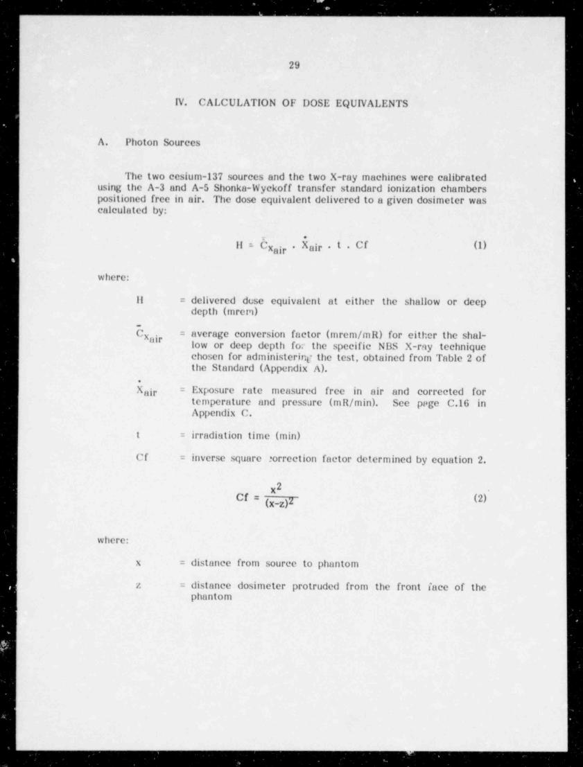
A. Photon Sources
The two ecsium-137 sources and the two X-ray machines were calibratedusing the A-3 and A-5 Shonka-Wyckoff transfer standard ionization chamberspositioned free in air. The dose equivalent delivered to a given dosimeter wascalculated by:
r .
11 = Cx ir . Xair . t . Cf (1)a
where:
11 = delivered dose equivalent at either the shallow or deepdepth (mren)
C = average conversion factor (mrem /mR) for either the shal-x"g'low or deep depth for the specific NBS X-ray techniquechosen for administerint? the test, obtained from Table 2 ofthe Standard (Appendix A).
X je = Exposure rate measured free in air and corrected foratemperature and pressure (mR/ min). See page C.16 inAppendix C.
t = irradiation time (min)
Cf = inverse square ':orrection factor determined by equation 2.
2x .
Cf = (x-z)Z (2)
where:
x = distance from source to phantom
z = distance dosimeter protruded from the front face of thephantom
_ _ _ _ _ _ _ _ _
,_ _ _ - _ _ _ _ _ _ _ _ _ _ _ __-_-___ - -_____ _-____ _ _ _ _ _ _ - _ _ - - _ _ _ _ _ _ - - - . _ _ _ _ _ _ _ _ _ _ _ _ _ _ _ _ _ _ _ _ _ _ _ _ _ _ - - _ - _ _ _ _ - _ _ _ . - _ - .
30'
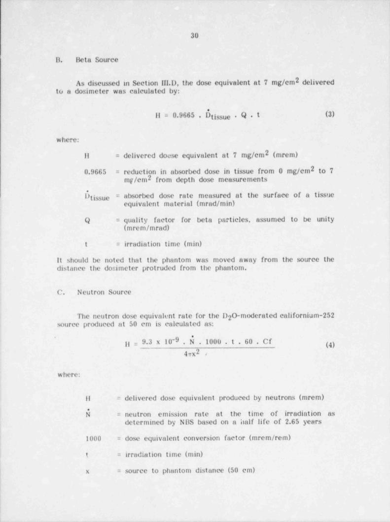
B. Beta Source
2 deliveredAs discussed in Section III.D, the dose equivalent at 7 mg/cmto a dosimeter was calculated by:
11 = 0.9665 . 0 tissue . Q . t (3)
where:
11 = delivered docse equivalent at 7 mg/cm2 (mrem)
0.9665 = reduction in absorbed dose in tissue from 0 mg/cm2 to 7mg/cm2 from depth dose measurements
0 ssue = absorbed dose rate measured at the surface of a tissuetiequivalent material (mrad / min)1
! Q = quality factor for beta particles, assumed to be unity,
(mrem / mrad)!
t = irradiation time (min)
It should be noted that the phantom was moved away from the source thedistance the dosimeter protruded from the phantom.
|
C. Neutron Source!
i The neutron dose equivalent rate for the D 0-moderated californium-2522) source produced at 50 cm is calculated as:a
'
| gg = 9.3 x 10⁻⁹ .1000 . t . 60 . Cf (4)4xx2,
where::
Il = delivered dose equivalent produced by neutrons (mrem)4
= neutron emission rate at the time of irradiation as'
determined by NBS based on a half life of 2.65 years
1000 = dose equivalent conversion factor (mrem / rem)
t = irradiation time (min)
x = source to phantom distance (50 cm)
_ _ _ _ _ _ _ _ . . _ _.. __ . _ _ _ _ _ _ _ _ _ . _ , __ _ . ~ .
- _ . .
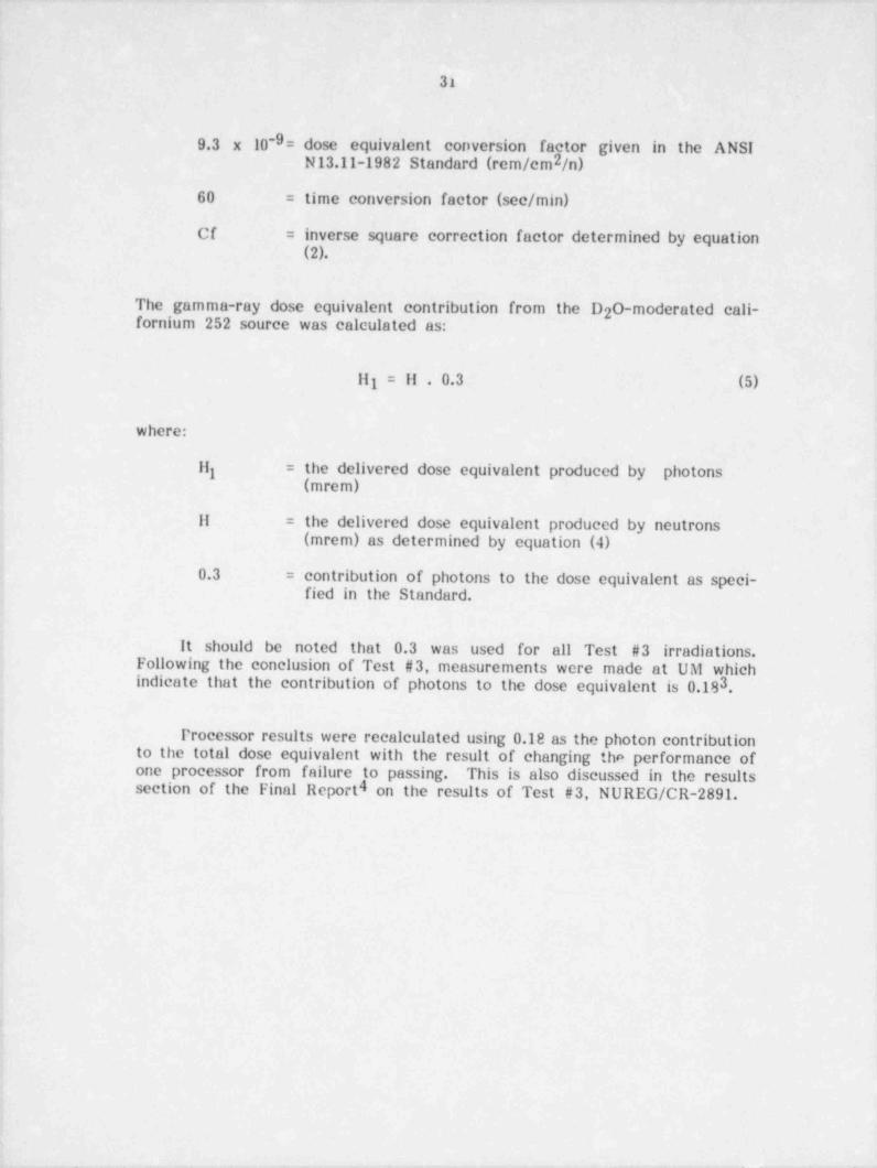
31
9.3 x 10-9= dose equivalent conversion factor given in the ANSI '
2N13.11-1982 Standard (rem /cm /n)
60 = time conversion factor (sec/ min)
Cf = inverse square correction factor determined by equation(2).
| The gamma-ray dose equivalent contribution from the D 0-moderated cali-2 )fornium 252 source was calculated as:
f III = II . 0.3 (5)
where:.
Il = the delivered dose equivalent produced by photonsi(mrem)
II = the delivered dose equivalent produced by neutrons(mrem) as determined by equation (4)
0.3 = contribution of photons to the dose equivalent as speci-fied in the Standard.
It should be noted that 0.3 was used for all Test #3 irradiations.Following the conclusion of Test #3, measurements were made at UM whichindicate that the contribution of photons to the dose equivalent is 0.18 ,3
l'rocessor results were recalculated using 0.18 as the photon contributionto the total dose equivalent with the result of changing the performance ofone processor from failure to passing. This is also discussed in the resultssection of the Final Report 4 on the results of- Test #3, NUREG/CR-2891.
|
4
i
. _ _ . _ .- . . - . . . - - . . _ - - ~ . . _ _ . . , . . , . - - - - _ . _ _ - . . _ . . . - - _ - _ . -. _
_ _ _ _ _ _ _ _ _ _ _ _ _ _ _ _________ __
32
V. ADMINISTEltlNG TEST #3
A. Technician Trainingi.
| Each person employed to work on the pilot study received trainingcommensurate with his or her assigned duties and responsibilities. The purposeof the Standard and the reasons for conducting the pilot study were fullyexplained. The individual worker's responsibility in consistantly performingthe dosimeter irradiations in the prescribed manner was stressed.
As discussed in Section III.F, technicians were trained in the safeoperation, both radiologically and occupationally, of a single sourec. When thetechnician demonstrated his or her ability to use the source safely, to positionthe phantom properly, and to understand the hazards of a particular source bya practical examination, he or she was permitted to irradiate dosimeters withthat sourec. The two full-time technicians were trained on each sourec, and
the part-time technicians were trained only on the sources for which theirassistance was required.!
Each technician was shown the proper operation of the radiation surveymeters, and the procedures to follow in the event of any unusual situation.There were no unusual events during Test #3, presumably due to the designsof the radiation sources and the technician training.
In addition to radiological training the technicians received occupationalsafety training. The major potential occupational hazards included: possibleelectric shock from high voltage equipment; falls from the ladder used withthe neutron source; and muscle strain from moving the phantum. Theseoccupational hazards were identified to the technicians, and safe work habitswere outlined. The lack of any major accident during Test #3 was presumablydue to a successful training program.
One minor flaw in our training program may have been that we did notissue written examinations to the technicians, nor did we document the datesof practical examinations. It is our recommendation that the permanenttesting laboratory document the training of each technician with a written andoral examination (see llecommendation number 12).
IL Scheduling Test #3 Irradiations)
A memorandum was sent to personnel dosimetry processors on September1,1981 inviting them to participate in Test #3. A copy of this memorandumis given in Appendix C (pg. C.1). This memorandum contains a fifteen pointSummary of Test #3 describing the changes in the Standard and the rules of
33
participating in Test #3. It alsa contains a registration form the processorswere to fill out and return to UM indicating the categories in which theywished to participate, and the number of types of dosimeters they wished tosubmit.
Test #3 consisted of two three-month testing sessions (November,December, and January, 1031-82, and February, March and April, 1982).Thirty-five percent of the processors chose to be tested during the first three-month period, and the remaining 65% chose the second three-month period.
The Standard requires 15 dosimeter irradiations for each category test.The processors were instructed to send five dosimeters plus a few additionalbadges to be used if a dosimeter was misirradiated for each category in whichthey were to be tested along with some shipping controls for each of the threemonths. Processors who chose to participate in Category VIII (neutron plusgamma) were also instructed to send six additional neutron dosimeters whichwould be irradiated by the UM to 500 mrem (neutron) from the D 0-2moderated californium-252 source to serve as a calibration to the testinglaboratory's neutron source.
Confidentially between the testing laboratory and the processors wasmaintained during Test #3. An identification code number was assigned toeach processor. If a processor submitted more than one type of dosimeter, aunique I.D. code number was assigned to each dosimeter type. These codenumbers are used to discuss results without disclosing the processor's name.
C. Iteceiving and Organizing Dosimeters
After receiving the registration form (see Appendix C) from theprocessor, an envelope and data sheet (s) were prepared for each category inwhich the processor wished to be tested. The proecssor's name andidentification code were put on the envelope and data sheet (s) with theentegory designation. If a processor participated in all eight categories, theyhad eight envelopes. For each month the processor sent badges, the date ofreceipt of the badges was recorded on a log sheet, and badges were distributedto the various envelopes. L)osimeter numbers were recorded on the envelopeand the data sheet (s) in the same order. Photocopics of an envelope for asingle irradiation category and a double irradiation cetegory are shown inAppendix C on pages C.6 and C.7, respectively. These envelopes show thecategory, processor I.D. code, dosimeter numbers and dates of irradiation.The envelope was placed in a box with other envelopes of the same category,and the data sheets were placed in a ring binder with other data sheets fromthe same category. The processor's I.D. code number was also written on thebox in which the dosimeters were sent to the testing laboratory. Shippingcontrol and spare dosimeter numbers were not recorded, and were left in theshipping box unless needed. On pages C.19 through C.29 in Appendix C is acomplete set of data sheets for a hypothetical processer. When thedosimeters were irradiated, the date of irradiation was written by thedosimeter numbers on the envelope. The data sheets will be further discussedin the following section.
- _ _ _ _ _ _ _ _ _ _ _
!
34
D. Irradiating Dosimeters
The delivered dose equivalents for Test #3 were chosen using a log-random method. That is, in each category, the values of the logarithms of thedelivered dose equivalent (or absorbed dose) are chosen at random. This hasan effect of skewing the distribution of the delivered dose equivalents towardthe lower end of the test irradiation range. For categories VI, Vil and Vill,dealing with mixed radiation fields, the component ratios were chosen atrandom. In these categories, the delivered dose equivalent of the largercomponent must not be greater than three times that of the smallercomponent, as stated in section 3.6 of the Standard. This method is alsodescribed in section A3 of the ANSI N13.11-1982 Standard (see Appendix A tothis report). The dose equivalent assignment for each of the 15 dosimeters ina given category was listed on a master form by line number. Since theexposure rates for the ecsium-137 sources and the absorbed dose rate for the
2strontium / yttrium-90 source at the surface (0 mg/cm ) are tx)sted by theirrespective sourec, it was decided to convert the dose equivalents to eitherexposure or absorbed dose to eliminate the technician having to performunnecessary calculations. Pages C.8 through C.15 in Appendix C contain thedose assignment sheets used for the first round of Test #3.
On the day of irradiation, a log book containing the data sheets for aparticular category and the box of envelopes for the category were taken tothe irradiation facility. Dosimeters from six processors were irradiatedsimultaneously (except for the beta-particle som ce). The data sheets for eachof the six processors were spread on a table, and their envelope was placedby the data sheet. As irradiations were completed, the irradiation date, timeof day, irradiation time, exposure rate, and phantom position were recorded onthe data sheets. For each of the X-ray categories, an X-ray spectrum sheetshowing the X-ray beam characteristics of IIVI,3 and h was documented andstored with the strip chart recorder paper for that day. Page C.16 inAppendix C shows a sample X-ray spectrum shmet, and the data sheets for ahypothetical processor are included on pages C.19 through C.29 in Appendix C.
For irradiations in the mixture categories, the dosimeter numbers wererecorded on the same line number of both data pages. Misirradiateddosimeters were recorded in the log book with the rephtcement dosimeternumber, and were identified on a memorandum included with the dosimeterswhen they were returned to the processor.
E. Iteturning Dosimeters
Following the completion of all irradiations for a given month, theenvelopes for all categories were examined to insure that each had anirradiation date. The data sheets for each category were also examined toverify timt all the irradiations had been completed. The dosimeters were then
- - - - _ _ _ _ ___
. - - .
35
returned to their original shipping boxes. Dosimeters irradiated in theaccident categories (I & II) and the neutron plus gamma category (VIII) wereidentified on a form memorandum (See pg. C.18). Volded dosimeters were alsoidentified on this memorandum. A memorandum identifying the neutrondosimeters given the calibration irradiation was sent during the first month oftesting. Samples of these memoranda are given on pages C.17 and C.18 inAppendix C.
After all the shipping boxes had been filled with the dosimeters andproper memoranda, they were scaled and mailed first class. All shipping boxeswere marked "dc not X-ray " Point 8 of our memorandum of September 1, 1
1982 " Summary of Test #3" (pg. C.3 in Appendix C) asked the processors toship their dosimeters in a container that would survive a round trip throughthe mail. liceause of this, we did not have to replace any shipping containersduring Test #3.
Section 3.1.3 of the Standard requires the processor to report his resultsto the testing laboratory within 60 days of his receipt of the dosimeters.Failure to do so would result in the corresponding test results being voided.13ecause this pilot study was based on volunteer participation, we were lenientwith processors on this point. In order to implement this rule of the Standard,the proficiency testing laboratory will have to return dosimeters to processorsusing registered mail with a return receipt sent to the testing laboratory. Theprocesssor will have 60 days from the date on the return receipt to submit hisreported dose equivalents to the testing laboratory (sec llecommendationnumber 4).
F. Analysis of lleported Dose Equivalents
Until the completion of irradiations for the third month of testing thedata sheets for all processors were kept in ring binders by category. Followingthe irradiations, the data sheets for a particular processor were assembledfrom the r.ng binders and stored in the proecssor's file. When all the reporteddose equivalents were received from a processor, they were entered onto thedata sheets. Computer punch-cards were made and the data were enteredinto a computer. A computer program calculated the delivered doseequivalent to each dosimeter from the data sheet, applied correction factorsfor inverse square, C values, and the photon contribution from the neutronx,
source. The computer program also calculated the performance index, P, foreach doshneter, the average performance for the fifteen dosimeters in acategory, P, and its associated standard deviation, S. A value of |Pl + S wascalculated and compared to the tolerance limit, L, to determine if a processorpassed or failed the entegory, and a report of the results was printed. A final
4report on the results of Test #3, NUltEG/ Cit-2891 discusses these results. Alisting of the computer data file for a hypothetical processor is given on pagesC.30 through C.32 in Appendix C. A listing of the computer program used toanalyze the Test #3 data is given on pages C.32 through C.40 in Appendix C.
,
364
,
,
i A sample report of the Test #3 results for a hypothetical processor is incluoedj on pages C.41 through C.58 in Appendix C. Because of a magnetic computerj tape system, the computer data for Test #3 could not be altered without
alerting the testing laboratory director.4
.
G. Quality Assurance Measures
For all irradiation sources with the exception of the strontium / yttrium-90 source six dosimeters were irradiated from six different processors at agiven time whenever possible. This procedure provided seven pieces of data!
'for analysis for most cases; reported data from six processors and !rradiationdata from the testing laboratory. If a processor claimed that their dosimeter4
was misirradiated or not irradiated, six other pieces of information could be;
j examined to determine if the processor is in error, or if the testing laboratory,
had made an error. in some cases it was not possible to irradiate dosimetersj from six proecssors. For these cases, a minimum of three dosimeters were; irradiated. A unique code number for each dosimeter was produced from thej date, time of day and phantom position recorded on the data sheets. These] code numbers could be searched for numbers identical to the dosimeter in
question, with the exception of the last digit which was the phanton position.,
This procedure worked well for Test #3. One time this procedure indicated.
that a processor was in error, and another time indicated that the testingq laboratcry had misirradiated the dosimeters.
4
i Other quality control procedures included: check of the X-ray spectrumsheets for the X-ray irradiations, and the strip chart recording; verification ofthe phantom positioning prior to the beginning of irradiations for a given day;and periodic checks of the timers. After the report of a processor's Test #3s'results was produced, any categories failed were visually scrutinized by the
, testing laboratory director or assistant director to check for keypunching orj transcription errors made by the testing laboratory.
)
i
|11
1
,
i
. . , . ,. _ - ,,, ,._.m- , -. . ,. - - _ . , _ _ _ . _ _ _ . . . ,_m__ _. . - _ _ . . _ _ _ _ _ . _
_. . _. . _ __ , _ __
4
37
;
VI. RECOMMENDATIONS*
#
A. Implementation of Recommendations from Tests #1 end #21
Recommendations for procedural changes which would improve the<
) general operational procedures of the testing facility for any further rounds of'
proficiency testing were formalized after Tests #1 and #2 in the originallProcedures Manual . These recommendations consisted of: 1) using solid
; phantoms; 2) the testing laboratory replacing substandard dosimeter shippingcontainers with sturdy containers; 3) requiring receipt of the dosimeters at the
i testing facility no later than the 5th day of the month; 4) using a beamj monitor for each source.
,
!
!4~
During Test #3 the testing laboratory made an effort to follow these| recommendations. Solid Plexiglas phantoms were made as described above,
and sturdy phantom stands were constructed of aluminum to replace the ,
] tripods previously used to support the phantoms. Participants in Test #3 wereinstructed to ship their dosimeters in a sturdy shipping container that woulda
j survive a round trip through the mail system (see Summary of Test #3, point#8 page C.3 in Appendix C). Processors were also instructed to have their-
I dosimeters arrive at the testing laboratory by the 5th of the month, or they! would be returned unirradiated (see point #7 of Summary of Test #3 page C.3i in Appendix C). With the exception of a few processors who telephoned to
inform the testing laboratory that their dosimeters would be late, all1,
dosimeters were received by the fifth day of a testing month. Beam monitorswere used for the X-ray n achines, as previously described, and an extensiveeffort was made to develop an electrical system which would give the testinglaboratory a beam monitor for every radiation source. Several systems werefound which would give the testing laboratory the capacity of having beammonitors at each radiation source, but the cost of these systems was notwithin the budget of the nilot study,
,
D. Recommendations from Test #3;
1
i
Additional experience gained by the testing laboratory during Test #3i
| has lead to the following recommendations to improve the general operationalprocedures of the permanent proficiency testing laboratory.'
1. Ileam Monitors
.
The beam monitor system used for X-ray irradiations as described in[! section C.1 was an improvement over the system used for Tests #1 and #2 ini that a more sensitive electrometer was used with the ionization chamber.. A
minor drawback to the system used for Test #3 is that there is a slight break'
i
1
a
. - - . . - . . ,- c-- ._--. - -r. - ss ..s-. ,%-. .e-. - ,,.-- . _ ,-
! 38L
!
in continuity when the ionization chamber is moved from its free in air|
position at one of the phantom position locations to a position at the side ofthe phantom when the phantom is put back on its stand. A better systemwould be to have an ionization chamber in the same position in the X-ray
! beam as with Tests #1 and #2, but use more sensitive electronics with this| chamber as was donc in Test #3. A system to record the raising and lowering'
of the isotope radiation sources is also needed to document the trueirradiation times. We recommend a beam monitor for each radiation source.
2. Laser Phantom Alignment
The site visit team from NBS suggested using laser beams to align thephantoms (see page B.34 in Appendix B). The suggestion was not within therealm of the Test #3 budget. A laser beam coupled with an alarm system toindicate to the technician that the phantom is not properly aligned would bean asset to the permanent testing laboratory.
3. Multiple Dosimeter Beta-Particle Irradiato-
As repeatedly mentioned above, the beta-particle source used for Tests#1, #2, and #3 could be used to irradici only one dosimeter at a time. Thiscaused two major problems. First, the amount of time required to completeirradiations for Category V (beta) and it'e beta component of Category Vil(beta plus gamma) was much greater than for any other category. The amountof time required to complete these irradiations, and therefore the cost oftesting, could be reduced by using a beta-particle source which could irradiatemore than one dosimeter at a time. Second, the quality control procedure ofirradiating more than one dosimeter at a time could not be used with thecurrent beta-particle source. This procedure has been shown to be a usefultool in solving disputes between a processor and the testing laboratory withthe other sources. As recommended by the NBS site visit Report (page B.37)the permanent testing laboratory should use a strontium / yttrium-90 beta-particle source that can irradiate more than one dosimeter at a time. TheNRC is having such a source built at this time.
4. Shipment of Dosimeters
(
Dosimeters should be sent from the permanent testing facility viaregistered mail with return receipt. This is the only way in which the 60 dayreporting of data specified in Section 3.1.3 of the Standard (see page A.13 inAppendix A) can be enforced. The additional cost of this was not budgetedfor in Test #3. There were two instances of dosimeters being lost in the mail,which would be documented and possibly eliminated by sending the dosimetersvia registered mail with return receipt. Also, if the return receipt is notreceived by the permanent testing laboratory within a specified time, a traceshould be initiated for the dosimeters.
39
5. Reduction in Iland Written Data
As can be observed from the data sheets given in Appendix C, there area lot of hand written data from Test #3. This was also evident during Tests#1 and #2 as can be seen from the data sheets of Appendix B to the previous
lProcedures Manual . An improvement to these testing procedures would be tocliminate the need for a technician to write data by hand, thereby eliminatingthe potential for clerical errors by the testing laboratory. The permanenttesting laboratory should develop a procedure for hard copy verification of alldata transmitted from data sheets to a computer, to minimize clerical errors.Clerical errors from hand written data were not a major problem during Test#3. Ilowever, a few reports were sent to processors which showed that theyfailed a category due to a testing laboratory clerical error. When these errors
,
were identified, they were corrected and new reports were sent to the'
processors. When testing becomes manditory, the cost of failure will besignificant (both to a processor and to the testing laboratory). The testinglaboratory will have to prove that it has not made any clerical errors. Oneway to do that would be to eliminate data written by hand.
G. Timer Checks
Based on our experience with the cesium-137 sources, the timers for allsources should be checked, and the check should be documented at the start
of daily irradiations.
7. Guidance for Direct Reading Dosimeters
Section 1.2 of the Standard (page A.2 in Appendix A) states that theStandard covers "... tuts of personnel dosimetry performance with any type ofdosimeter whose reading is used to provide a cumulative personal irradiationrecord cf an individual." This allows for the testing of direct readingdosimeters if they are used as the primary means of personnel dosimetry.Ilowever, the Standard does not provide guidance for the testing laboratory onhow to handle these direct reading dosimeters. If direct reading dosimetersare to be tested, procedures for zeroing the dosimeters prior to irradiation andreading these dosimeters after irradiation as well as who should perform theseprocedures, need to be addressed for the permanent testing laboratory.
8. Employee Training
The permanent testing laboratory should maintain records of writtenand/or practical competency testing for each testing laboratory employeewhich demonstrate: (1) their ability to use the radiation sources properly; (2)their ability to conduct irradiations in accordance with ANSI N13.11-1982; (3)their understanding of the safety interlock systems of each source; (4) their
i
40
understanding of the use of radiation survey meters; and (5) their under-standing of radiation health effects.
9. Telephone Conversation Log Book
Due to the confidentiality of the pilot study, a telephone call log bookwas not kept. Because of the nature of the proposed testing program, it isrecommended that the permanent proficiency testing laboratory keep adetailed log book on the nature of each telephone call with processors. Acopy of any transcribed notes of a telephone call should be sent to theprocessor. This system would eliminate any misunderstanding between theproficiency testing laboratory and the processor.
10. Neutron ''alibration Irradiations
Since most neutron dosimeters are calibrated to the specific neutronspectrum observed by the worker, the permanent proficiency testing labora-tory should offer a set of calibration irradiations to the neutron source usedfor testing.
11. Documentation of Voided Dosimeters
The permanent proficiency testing laboratory should develop a procedurefor documenting dosimeters voided by the testing laboratory. This docu-mentation should consist of a form showing the voided dosimeter number, itsreplacement, the reason for voiding, the category for which it was voided, thedate and time, and the technician's name who voided it.
12. Occupational and Radiological Safety Procedures
General ocet.>ational safety and radiological safety procedures should bewritten and followi d by the proficiency testing laboratory. These proceduresshould be read and observed by each testing laboratory employee. Writtendocumentation in the form of a signed affidavit should be kept on file for eachtesting laboratory employee. This will help to insure that the performancetesting program is conducted in a safe manner.
|
__ _ _ _ _ _ _ _ _ _ _ _ _ _ _ _ _ _ _ _ _ _ _
41
VII. ACKNOWLEDGEMENTS
,
The authors wish to express their appreciation to Roberta Purdon,Patricia Brazil, Tim Almburg, Kathy IIerron, and Sandra Keavey for theirtremendous effort on this pilot project. We would also like to acknowledgethe technical assistance and advise from Margarete Ehrlich, Tom Loftus.Charlie Eisenhauer, and Jack Pruitt of NBS. Also the coordination efforts ofNancy Dennis of the NRC were a great help in contributing to the success ofthe pilot study.
I
P
1
. ..
- _ - _ _ _ _ - _ _ _ _ - _ _ _ _ _ _ _ _ - _ _ _ _ _ _ _ . __ _ _ _ _ _ _ .
42
Vill. REFERENCES
I 1. Plato, P. and lludson, G. Performance testing of personnel dosimetryservices: procedures manual, NUREG/CR-1063, National Technical In-formation Service, Springfield, Virginia 22161 (January,1980).
I 2. Schwartz, R. B. and Eisenhauer, C. M. The design and construction ofD 0-moderated Cf-253 source for calibrating neutron personnela 2
dosimeters used at nuclear power reactors, NUREG/CR-1204, NationalTechnical Information Service, Springfield, Virginia 22161 (January,1980).
f 3. Mcdonald, J., Griffith, R., Plato, P., and Miklos, J. Measurements ofgamma-ray dose from a moderated 252Cf source, NUREG/CR-2957.National Technical Information Service, Springfield, Virginia 22161 (inPress).
4. Plato, P. and Miklos, J. Performance testing of personnel dosimetryservices: Final Report of Test #3, NUREG/CR-2891 National TechnicalInformation Service, Springfield, Virginia 2217.1 (in press).
_

,
APPENDIX A
The HPSSC Standard, adopted in June, 1981used for Test #3 of the pilot study.
.
4
-
, - - - - .. .. -.
A.1
HPSSC WG 1.4
I Draft Standard
Criteria for Testing Personnel Dosimetry Performance
Health Physics Society
i
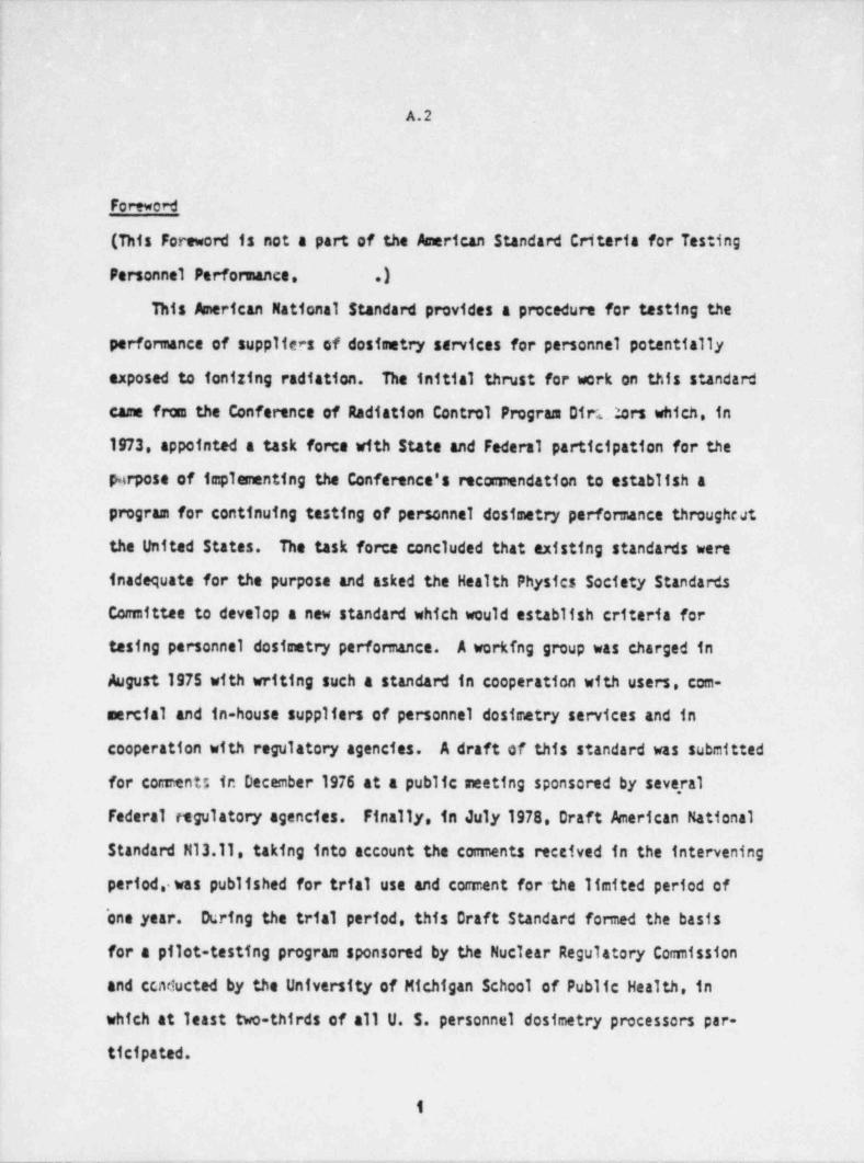
-.- -
|
A.2 4
I'
|
Foreword |
(This Foreword is not a part of the American Standard Criteria for Testing i
Personnel Performance. .)This American National Standard provides a procedure for testing the
performance of suppliers of dosimetry services for personnel potentially
exposed to ionizing radiation. The initial thrust for work on this standard
came from the Conference of Radiation Control Program Diri.Mrs which, in
1973, appointed a task force with State and Federal participation for the
porpose of implementing the Conference's recomendation to establish a
program for continuing testing of personnel dosimetry performance througheat
the United States. The task force concluded that existing standards were
inadequate for the purpose and asked the Health Physics Society Standards
Comittee to develop a new standard which would establish criteria fori tesing personnel dosimetry performance. A working group was charged in
August 1975 with writing such a standard in cooperation with users, com-
mercial and in-house suppliers of personnel dosimetry services and in
cooperation with regulatory agencies. A draft of this standard was submitted
for coments in December 1976 at a public meeting sponsored by several
Federal regulatory agencies. Finally, in July 1978. Draft American National
Standard M13.11 taking into account the coments received in the intervening
period, was published for trial use and coment for the limited period of
'one year. During the trial period, this Draft Standard formed the basis
for a pilot-testing program sponsored by the Nuclear Regulatory Comission
and ccnducted by the University of Michigan School of Public Health, in
which at least two-thirds of all U. 5. personnel dosimetry processors par-
ticipated.
1
___. - -- _ - _ _ , - _ . .- - .. .. - - .
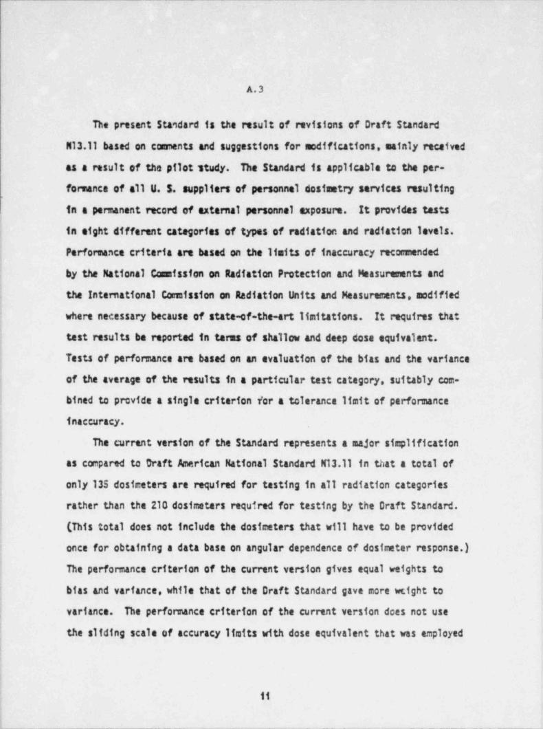
A.3
The present Standard is the result of revisions of Draft Standard
M13.11 based on coments and suggestions for modifications, mainly received
as a result of the pilot study. The Standard is applicable to the per-
formance of all U. 5. suppliers of personnel dosimetry services resulting,
in a permanent record of external personnel exposure. It provides tasts
{ in eight different categories of types of radiation and radiation levels.
j performance criteria are based on the limits of inaccuracy reconnended
| by the National Commission on Radiation protection and Measurements and
| the International Comission on Radiation Units and Measurements, modified
where necessary because of state-of-the-art limitations. It requires thati
j test results be reported in tarus of shallow and deep dose equivalent.
| Tests of performance are based on an evaluation of the bias and the variance1
! of the average of the results in a particular test category, suitably com-!
! bined to provide a single criterion for a tolerance Ifmit of perfonnancei
j inaccuracy.
| The current version of the Standard represents a major simplificationi
; as compared to Oraft American National Standard N13.11 in that a total of1
j only 135 dosimeters are required for testing in all radiation categoriesi! rather than the 210 dosimeters required for testing by the Draft Standard.!
(Thistotaldoesnotincludethedosimetersthatwillhavetobeprovided'
I once for obtaining a data base on angular dependence of dosimeter response.)ij The performance criterion of the current version gives equal weights to
i bias and variance, while that of the Draft Standard gave more wcight toj
| variance. The performance criterion of the current version does not use
| the sliding scale of accuracy Itaits with dose equivalent that was employedi,
i!
j 11:
(___ _ _ _ _ _ _ _ _ _ - _ . _ - - _ - . - - - - - _ _ - _ - - - - _ _ _ - _ - - - . - - - -_ _ _ _ _ _ _ _ - _ __ -- -
. - - _ _ __ .
A.4
in the Draft Standard and is recomended on the basis of rattation protec-
tion considerations. The sliding scale was not used because the ofict study
had shown that its use did .70t appreciably alter the test results attd
because tightening performance criteria below a few hundred arem (a few
a Gy) provides suans for bringing to the processor's attention that the
regulating agencias presently require measuring capability at these low |
levels.,
I
Edward J. Va11ario, Chairman Joseph G. BellianVernon T. ChilsonEric L. GeigerRichard V. GriffithRoy A. ParkerLouie M. Scott !
John F. ScmersA. N. Tschaeche
|,
111
- _. -_ .
4
A.5
The Working Group responsible for the development of this Standard had the
following members:'
*Margarete Ehrlich, Chairman Vernon T. Chilson
(National Bureau of Standards) (Florida Power and Light Company)
; Eric T. Clarke(Technical Operations, Inc.)'
Royer 8. Falk,Rockwell Atomics International)
: Eric L. Geiger*
(Eberline Instnment C'orporation)
! Lowell Nichols(Battelle-Nortfreest Laboratories);
Harley V. Piltingsrud1
] (Bureau of Radiological Health, FDA)
: Phillip Plato! (Univ.ofMichi
Public Health) gan School of);
j Bernard H. Weiss.
(Nuclear Regulatory Comission).
) * Active only during the * period o'f deliberations' leading to the December 1976
i draft of this Standard.l
;
i
I
i
f
1
i.
ft
'_ _ _ _ . - _ - - -
CONTE.NT3
SECTION PAGE
1. Purpose and Scope 1. . . . . . . . . . . . . . . . .
1.1 Purpose 1. . . . . . . . . . . . . . . . . .
1.2 54 ope 1. . . . . . . . . . . . . . . . . . .4
1
2. Definitions 2. . . . . . . . . . . . . . . . . . .
2.1 AbsorbedDose(D) 2. . . . . . . . . . . . . . .
2.2 Dose Equivalent (H) 2. . . . . . . . . . . . . .
; 2.3 Shallow and Deep Absorbed Dose (0, and O ) or Shallow cndd
Deep Dose Equivalent (H and H ) 2. . . . . . . . . .g d
2.4 Protection Dosimetry 3. . . . . . . . . . . . . .
| 2.5 Accident Desimetry 3. . . . . . . . . . . . . .
! 2.6 Dosimeter 3. . . . . . . . . .. . . . . . . .
\.
. . . . . . . . . . . . . . . . . . 3| 2.7 Processor
32.8 Test .- . . . . . . .. . . . . . . . . . .
2.9 Blind Testing 4. . . . . . . . . . . . . . . .
42.10 Testing 1.aboratory . . . . .. . . . . . . . . .
*42.11 Test Category . . . . . . . . . . . . . . . .
2.12 Performance Quotient (P ) 4. . . . . . . . . . . .g
2.13 Bias (B) . ' . 4. . . . . . . . . . . . . . . .
2.14 Standard Deviation (5) 5. . . . . . . . . . . . .
,
3. Test Procedure 5. . . . . . . . . . . . . . . . . .
3.1 Administrative Procedure 5. . . . . . . . . . . . .
3.2 Test Categories and Test Ranges 6. . . . . . . . . .
3.3 Radiation Sources 7' . . . . . . . . . . . . . . .
3.4 Phantom Construction 8. . . . . . . . . . . . . .
3.5 Irradiation Conditions 8. . . . . . . . . . . . .
v
. _ _ _ _ - _ _ - _ _ . _ . _ _ _ _ _ - - - . -
.
A.7
i CDNTENT3, Contd.
IXCTIDN PAGE
3.6 telection of Irradiation Levels 9. . . . . . . . . .
3.7 A s'enment of Dose Equivalent (or Absorbed Dose) Values 9. .
3.8 Stucy of Angular Dependence of Response 11. . . . . . .
4. Character ting the Performance 11. . . . . . . . . . . .
4.1 Perft enance Criterion 11. . . . . . . . . . . . .
4.2 Performance Evaluation 11. . . . . . . . . . . . .
Table 1 Te:t Categories. Test Irradiation Ranges, and Levels . 12.
Table 2 Coni trsion Factors for Computing the Dose Equivalent
(ortneAbsorbedDose)fromExposure 13. . . . . . .
5. References to th. Text 14. . . . . . . . . . . . . . .
Appendices. ,
Appendix A Test C4tegories and Test Irradiations 15. . . . . .
A1 Types of radiation Included in Table 1 15 i. . . . . .
A2 Test Irrad stion Ranges 16. . . . . . . . . . .
A3 Selection of Irradiation Levels 17. . . . . . . .
A4 Restrictions on Composition of Radiation Mixturns 18. .
A5 Source-to-Dosietter Distance 18. . . . . . . . .!
| A6 Rationale for Ute of Phantom for Tes.t Irrediations 19. ..
A7 Blind Testing 19. . . . . . . . . . . . . .
Appendix 8 Source Standardization 21. . . . . . . . . . .
'
R1 Photons 21. . . . . . . . . . . . . . . .
B2 Beta Particles 22. . . . . . . . . . . . . .,
B3 Neutrons 22. . . . . . . . . . . . . . . .
.
4
vi1
J
. - . . . - . . ._ _
-- _. .
A.8
CONTENTS, Contd.,
SECTIDN PAGE
Appendix C Interpretation of the Response of Gersonnel Dosimeters 24
C1 Use of the Shallow and the Deep ~ Dose Equivalent
(or Absorbed Dose) 24. . . . . . . . . . . . .
C2 Assignment of Values of the Dose Equivalentl
(or Absorbed Dose) 26. . . . . . . . . . . . . .
I Table C2 Conversion Factors for Computing Dose Equivalent
from Exposure 34*
. . . . . . . . . . . .
Appendix D Perfonnance Criterion and Perfonnance Evaluation 35. .
D1 Dependence of Perfonnance Quotient on Dose Equivalent
Level 35. . . . . . . . . . . . . . . . .
02 Significance of Testing over an Extended Period;
Other Aids for Obtaining Infonnation on a Processor's*
Protracted Perfonnance 35. . . . . . . . . . .,
1| D3 Choice of Tolerance Level. L 37. . . . . . . . .
| 04 Sourcas of Uncertainty Not Included in the Perfonnance
Evaluation 33. . . . . . . . . . . .. . . .
|
| 05 Measurement of Dependence of Cn-Phantom Dcsimeter
Response on Angle of Radiation Incidence 42. . . . .
Appendix E References to the Appendices 42. . . . . . . .
.
vii
_ . _ - . . ___ - _ . .. .
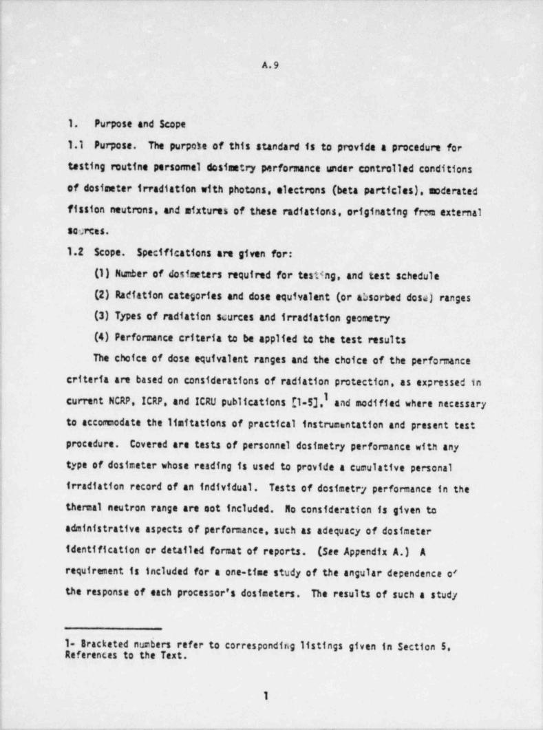
- . _ _ __ .
A.9
:
1
1. Purpose and Scope.
i 1.1 Purpose. The purpote of this standard is to pmvide a procedum for
testing mutine personnel dosimetry performance under controlled conditions.
of dosimeter irradiation with photons, electrons (beta particles), moderated
fission neutrons, and mixtures of these radiations, originating frem external
scerces.,.
| 1.2 Scope. Specifications are given for:
(1) Number of dosimeters required for testing, and test schedule
] (2) Radiation categories and dose equivalent (or absorbed dosa) ranges
(3) Types of radiation scurces and irradiation geometry
(4) Performance criteria to be applied to the test results
i The choice of dose equivalent ranges and the choice of the performancei
j criteria are based on considerations of radiation protection, as expressed in
current NCRP, ICRP, and ICRU publications [1-5],I and modified where necessary:
j to accommodate the limitations of practical instrumentation and present test!
| procedure. Covered are tests of personnel dostmetry perfomance with any
type of dosimeter whose reading is used to provide a cumulative personal
irradiation record of an individual. Tests of dosimetry performance in the
| thermal neutron range are not included. No consideration is given to
administrative aspects of performance, such as adequacy of dosimeter
1 identification or detailed format of reports. (See Appendix A.) A
requirement is included for a one-time study of the angular dependence of
) the response of each processor's dosimeters. The results of such a study;
i<
{ 1- Bracketed num6ers refer to corresponding listings given in section 5,i References to the Text.I
1
4
_ _ _ _ . . . _ . __ _ _ . . . __ _. _ _ _ _ __..__ _ ._ _ _ ._ - . _ . . - _
__ _ _- _ _ _ _ _ _ _ _ _ _ _ _ _ _ _ _ _ _ _ _ _ _ _ _ _ _ _ _ _ _ _ _ _ _ __ _ _ _ _ _
|
A.10
will give the processors a better understanding of the applications for
which their destmeters are suited. They will also provide a data base for
evaluating the need to include in future versions of this standard
perforesace test irradiations under other than perpendicular radiatio'n
ine.idence.
2. Definitions
In tht: :tendard, the definitions given in 2.1 through 2.14 shall apply.
2.1 Absorbed Dose (D). The energy absorbed per unit mass .at a spectfic
place in a material. The special unit of absorbed dose is the rad. The
SI unit of absorbed dose is joule per kilogram (J/kg). Its special name
is gray (Gyl. 1 J/kg a 1 Gy = 100 rad. As used in this standard, " absorbed
dose" stands for the absorbed dose in the saterial of interest, that is,
in soft tissue or in a phantom approximating soft tissue in composition.
NOTE: Ignoring trace elements, the composition of soft tissue is taken as
76.210,1T.1 1 C,10.1 1 H and 2.6 % N [6].
2.2 Dose Equivalent (H). The product of D. Q, and N, at the point of
interest in tissue, where D is the absorbed dose, Q is the quality factor,
and N is the product of any other modifying factors. The special unit of
dose equivalent is the rem. When D is expresse( in rads. H is in rams.
When D is expressed in rads. H is in sieverts. 1 Sv = 100 rem.
2.3 Shallow and Deep Absorbed Dose (D, and D.d) or Shallow and Deep Dose
Equivalent (H and H ). The absorbed dose or dose equivalent at thes d
respective depths of 0.007 cm and 1.0 cm in a sphere of soft tissue of a
density of 1 g cm-2 and a diameter of 30 cm. See also the Note to
definition 2.1.
2
_
- _ _ _ _ . _ . . _ _
__
1
A.11
2.4 Protection Dasinetry. Routine estimation of the shallow and deep dese'
equivalent for the purpose of ascertaining the effectiveness of radiation |
protection nearures in a given radiation facility. (See also taction C1
of Appendix C.)
2.5 Accident Oosimetry. Deterutnation of high levels of deep absorbed dose
resulting from uncontrolled conditions.
2.6 Dosimeter. Radiation sensitive element (s) in a holder (the holder
being considered a part of the dosimeter) used to provide a cumulative.
personal irradiation record of an individual.
2.7 Processor. Supplier of personnel dosimetry services. These services
include:
| (1) Furnishing dosimeters to the user
(2) Evaluating the readings of the dostmeters after their re*1rn in
terms of the shallow and deep dose equivalent as prescribed in this standard
(3) Recording the results
(,4) Reparting them to the user
2.8 Test. Procedure with the following sequence:
(1) Submission of dosimeters of a processor's current stock to a testing
laboratory over a period of several months, in numbers sufficient for the
specified trradiations in any one test category covered by c processor's
service.
(2) Irradiation of the dostmeters by personnel of the testing laboratory
using the type (s) of radiation specified for this test category (see 3.2).
(3) Evaluation by the processor of the response of the returned
dostmeters in terms of shallow and deep dose equivalent for tests of
protection monitoring, or in terms of deep absorbed dose for tests of
accident monitoring, as speciffed in Section 4.2.
3
. .
-_____ _____ - _ _ _ _ _ _ _ _ _ _ _ _ _ _ _ _ _ _ _ _ _ - _ _ _ _ _ _ _
A.12
(4) Submission of these evaluations to the testing laboratory
(5) Analysis of the submitted evaluations by the testing laboratory
(6) Reporting the results of this anlysis (also referred to as " test
results") to the processor
2.9 Blind Testing. Test of a processor's performance without the knowledge
of the processor.
2.10 Testing Laboratory. A group independent of the processor's operation
that is carrying out the procedures outlined in this standard.
2.11 Test Category. Each type, range of irradiation levels and energy of
radiation (or of radiation afxtures) for which separate tests are performed.
2.12 Performance Quotient (P ). For tests of protection dostmetry. theg
performance quotient for the ith dosimeter is defined as
(eq 1)g [Hj-H3/HgP E g
where H is the dose equivalent assigned by the' testing laboratory to theg
irradiated dostmeter, and Hj the corresponding dose equivalent reported by
the processor.
For tests of accident dostmetry the same definition appites, with the'
absorbed dose. D. replacing the dose equivalent. H.
NOTE: In this definition, H stands for H, t ; and D for D . No tests"
d
are performed for D .3
2.13 Bias (B). Tha. bias of the values o. . performance quotient. P . isg
set equal to the average of these values:n
8 I (1/n) P. (eq2)g
tal
where the sum is extended over all n values of P for a particular test in ag
given radiation category, and for a particular phantom depth (shallow or deep).
4
- - - _ _ _ _ _ - _ _ _ _ _ _ _ _ _ _ .
A.13
:
I 2.14 Standard Deviation (5). The standard deviation of the values of the' performance quotient, P . is:g
" *1/2i n
I (P, - 7)2i
3a (eq3)(,,z)_
.
where the sum is extended over all n values of P for a particular test in9
; a given radiation category, and for a particular phantom depth (shallow or
deep).
3. Test Procedure
| 3.1 Administrative Procedure
3.1.1 Information to Be Supplied to the Testing Laboratory. The|2 processor shall certify that the dosimeters submitted for each test are
,
representative of those supplied routinely to his users.
3.1.2 Number of Test Dostmeters. Fifteen dosimeters shall be irradiated
in any given test category. At least one additional dosimeter that is notI
'
to be irradiated.(a shipping control) shall be included with each dostmeter'
| shipment. If the dose interpretation from more than two of the dosimeters!'
irradiated in a given category have to be voided because of problems caused
by either the testing laboratory or the processor, statistical analysis of
the results in this category shall be delayed until replacement dosimeters,
have been submitted and irradiated, and the results reported by the processor
i to the testing laboratory.
3.1.3 Test schedule. (See also section D2 of Appendix D.) Each
test shall extend over a period ranging from three to six months. The )
test dostmeters shall be submitted to the testing laboratory in at least
three separate groups per test category. Each group shall be returned j
5
|
i !. _ _ _ _ - - -.---_ -__ .. . - - _
_ __ .-. _ .
- - - - - - - _ _ _ _ _ _ _ _ _
A.14
by the testing laboratory to the processor within one month from receipt.
The processor, in turn,, shall report his results to the testing laborat:ry
within 60 days of his receipt of the dostmeters. If he fails to do so,
the corresponding test resulu shall be voided.
3.1.4 Dissemination of Test Results. All test results on dostmeters
supplied by a given processor shall be ' reported to that processor at the
completion of each test. An estinate for the uncertainty of the assigned
values of the dose equivalent (or absorbed dose) shall be included in the
report. The processor shall not be permitted to change or void the reported
values after receiving the test results from the testing laboratory.
3.2 Test Categories and Test Ranges. The test categories and the test dose
equivalent (or dose) ranges are given in Table 1 and are further discussed in
Appendix A. Each processor shall be testad in the categories covered by his
service. Except for categories specifically identified as dealing with
radiation mixtures, only one type of radiation 'and one energy spectrum shall
be used per category in a given three- to six-months' testing period. For
all but the accident categories I and II and the neutron category VIII,
the categories in which individual destmeters were irradiated shall not be
divulged to the processor until after he has been sent the test results.
In the low energy photon category III the Nationa.1 Bureau of, Standards (NBS)
technique used for the irradiation shall not be divulged to the processor
until after he has been sent the test results.
6
_ _ .
A.15
3.3 Radiation Sources
3.3.1 The following radiation sources shall be available in the
testing laboratory, as a minimum.
(1) At least one Cs gamma-ray source. The source may be used
either in a beam-type irradiator equipped with a collimator or in free air. i
(2) At least one three-phase, twelve-pulse, full-wave rectified or
one constant potentf al x-ray machine operable in the range between 30 kV or
less and 250 kV or more. Among the accessories shall be beam filters of
compositions and thicknesses appropriate to produce continuous x-ray spectra
using the NBS techniques (73 specified in Table 1. An attachment for the
production of K-fluorescence x-ray sources of energies > 20 key should be
available for use in special procedures.
(3) A sealed "Sr/"Y beta-particle source equipped with a 100 cig/cm3
filter of an atomic number not to exceed 26.252
(4) A Cf neutron source. .isotropically moderated'by 15 cm of D 0.2
3.3.2 The standardization of all radiation sources and the calibration,
of all dosimetry instruments shall be carried out either at NES or with
calibrated reference class instruments snd with sources standardized at
NBS. (SeealsoAppendix8.) Standardization of all neutron sources in
terms af emission rates shall be carried out at NBS, and the schedule
for this procedure shall be based upon N85 recommendations. Sugges te'
techniq'ves for the use of calibrated instruments and standardized sources
i for determining test irradiation levels are given in Appendix 8.
1; I
7
_ _ _ _ .
___ -- . . .-
A.16
I
3.4 Phantom Construction (See also Section A6 of Appendfx A.)
The phantom shall be a methylmethacrylate slab, in size depending on
the radiation for which it is to be used:
For photons, the slab shall have a 30 cm x 30 cm cross section an(a
thickness of 15 ca;
for beta particles, the slab shall have a 30 cm x 30 cm cross section
and a thickness of at least 5 ca;
for neutrons, the slab shall have a 40 cm x 40 cm cross.section and a
thickness of 15 cm.
3.5 Irradiation Conditions
The test dostmeters shall be irradiated with phantom backing under
ambient laboratory conditions. For irradiation, they shall be attached to
the phantom surface facing the source (" front face"). When co111 mated
radiation beams are used, the central beam axis shall be perpendicular
to and pass through the centar of the front face of the phantom.
The distance hatween the center of the irradiation sources and the
phantom surface to nhtch the dostmeters are attached shall be not less than
1 m for the photon sourcas, not less than 35 cm for the "Sr/N Y source
and 50 cm for the neutron source. (See also Section A5 of Appendix A.)
If several dostmeters are to be irradiated simultaneously, precautions
shall be taken to keep the mutual interferenca at a level small compared
to the 25 percent ifmit in the uncertainty of the dose equivalent (or
absorbeddose]assignedtothedostmeters. In the case of neutron
irradiations, precautions also shall be taken to have no portion of the
dostmeters cleser than 10 cm to the phantom edge.
8
__ _ _ _ . _ _ _ . . - _ . - _ _ - . _ _ . _
_. -_-
A.17
At all but the neutron irradiation facility, the total back scatteri from the walls, ceiling, and floor of the irradiation room and from
j extraneous material in the vicinity of the source shall contribute only
j a small fraction of the ur, certainty in the value of dose equivalent (or
absorbed dose) assigned by the testing laboratory. At the~ neutron irradiation; facility for which this condition generally cannot be achieved, a correction
j shall be app 1ted to the assigned dose equivalent. (See also Section 83 of'
Appendix B.)
3.6 Selection of Irradf ation Levels;>
In each category, the values of the logarithms of the dose equivalent,
||
| (or absorbed dose) shall be chosen at randos. (See also Section A3 of
Appendix A.) In categories VI. VII, and VIII, dealing with afxed radiation| fields, the total assigned dose equivalent and the component ratios shall
, be selected at random. In these categories, the assigned dose equivalentii *of the larger component shall not be greater 1|han three times that of$ the smaller component.
3.7 Assignment of Dose Equivalent (or Absorbed Dose) Values
! The testing laboratory shall assign to each dostmeter values for thei
j shallow and deep dose equivalent (H, and N ) or the deep absorbed dose (D )*d d
The uncertainty in these values shall not exceed 25 percent, including the
uncertainty in the source standardization, the uncertainty in dostmeter! positioning and the uncertainty due to scattered radiation at the dostmeter
site, not stemming from the phantom; but excluding the uncertainty in the
j conversion. factors used to comput the dose equivalent (see Sections 3.7.1t
and 3.7.3) and in the assessment of the gamma-ray background of the neutron,
sources (see Section 83 of Appendix 8). For a discussion of the assignment>
| of the values of the dose equivalent see Section C2 of Appendix C.I
9
|'
_ _ _ _ _ _ . --_____ ,. _. - _ _ _ _ _ _ _ . - .. . .-. ___
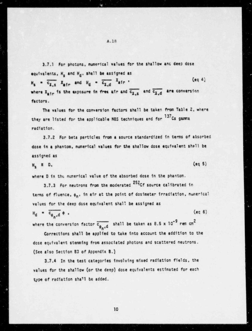
- _ _ _ _ _ _ _ _ _ _ _ _ _ _ __
A.18
3.7.1 For photons, numerical values for the shallow anc deep dose
equivalents, N, and N , shall be assigned asdb
C ,d air ** C I and H *Hs X,s nfr d X
where Xair is the exposure in fret air and c ,, and c ,d are conversiony I
factors.
The values for the conversion factors shall be taken from Table 2, where
they are listed for the applicable NES techniques and for Cs gama
radiation.
3.7.2 For beta particles from a source standardized in terms of absorbed
dose in a phantom, numerical values for the shallow dose equivalent shall be
assigned as
H I D. (eq5)s
where D is the nemerical value of the absorbed dose in the phantom.
24Cf source calibrated in3.7.3 For neutrons from the moderated
terms of fluence, $n, in air at the point of dosimeter irradiation, numerical
values for the deep dose equivalent shall be assigned as
NN$,,d * *Hd * C
be taken as 8.5 x d m Mwhere the conversion factor c'n d
sa
Corrections shall be applied to take into account the addition to the
dose equivalent stemming from associated photons and scattered neutrons.
(See also Section 83 of Appendix 8.)
3.7.4 In the test categories involving mixed radiation fields, the
values for the shallow (or the desp) dose equivalents estimated for each
type of radiation shall be added.
10
_- _ _ _ - _ _ _ _ _ _ _ _ _ _ _ _ _ _ _ _ _ _ _ _ _ _ _ _ _ _ _ _ _ _ _ _ _ _ _ _ _ _ _ _ _ _ _ _ _ _ _ _ _
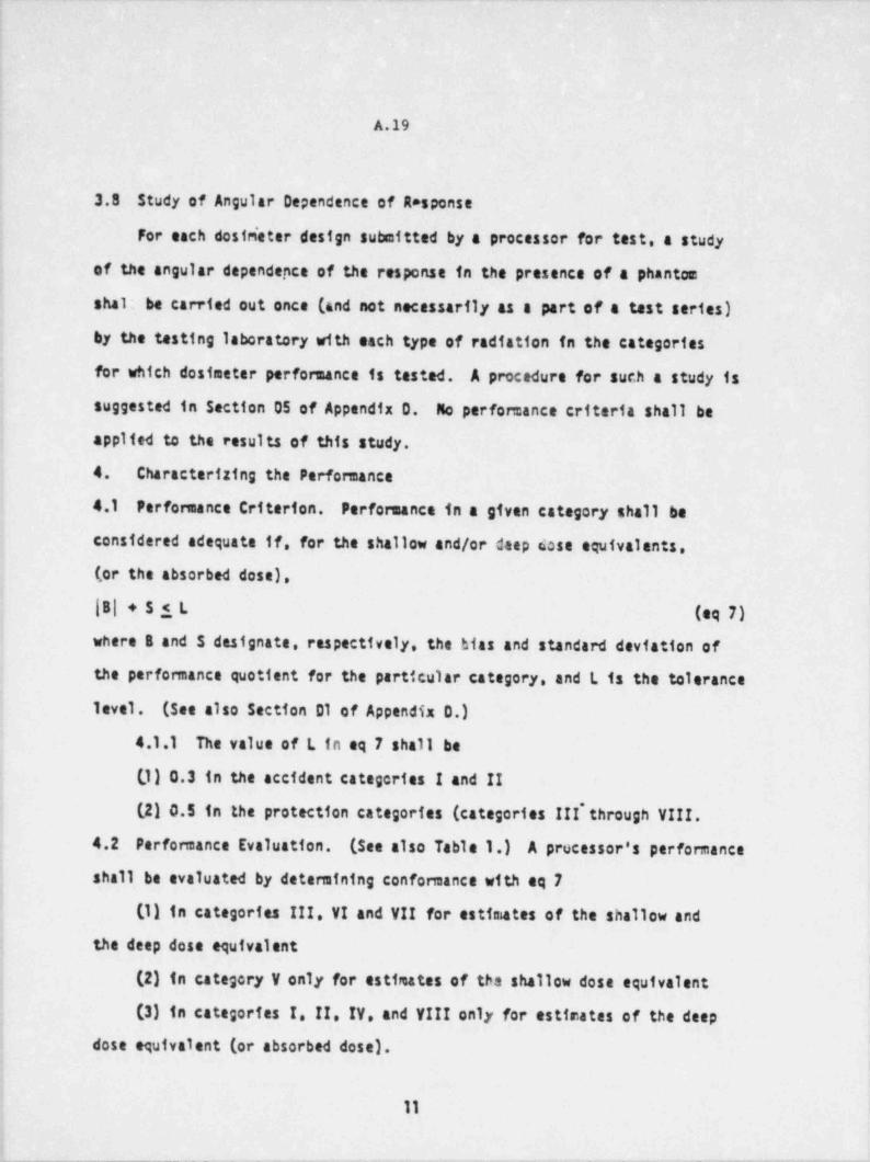
_ _ _ _
A.19
3.8 Study of Angular Dependence of A*sponse
For each destrieter design submitted by a processor for test, a study
of the angular dependence of the response in the presence of a phantom
shal' be carried out once (and not necessarily as a part of a test series)
by the testing laboratory with each type of radiation in the categories
for which dosimeter performance is tested. A procedure for sur.h a study is
suggested in Section 05 of Appendix 0. No perfomance criteria shall be
applied to the results of this study.
4. Characterizing the perfomance
4.1 Performance criterion. Perfomance in a given category shall be
considered adequate if, for the shallow and/or deep dose equivalents.
(ortheabsorbeddose).
|8|+5iL (eq 7)
where B and 5 designate, respectively, the hias and standard deviation of
the performance quotient for the particular category, and L is the tolerance
level. (See also Section D1 of Appendix 0.)
4.1.1 The value of L in eq 7 shall be
| (,1) 0.3 in the accident categories I and II
(2) 0.5 in the protection categories (categories III'through VIII.
4.2 Performance Evaluation. (See also Table 1.) A processor's performance
shall be evaluated by determining conformance with eq 7
(1) in categories III. VI and VII for estimates of the shallow and' the deep dose equivalent
] (2) in category V only for estimates of tha shallow dose equivalent
(3) in categories I. !!. !Y. and VIII only for estir.ates of the deept
dose equivalent (or absorbed dose).>
|
11
_ _ _ _ _ . _ .- . _ -- _ - _ _ - _ - _ _ - . _ _ _ _ _ _ _ -
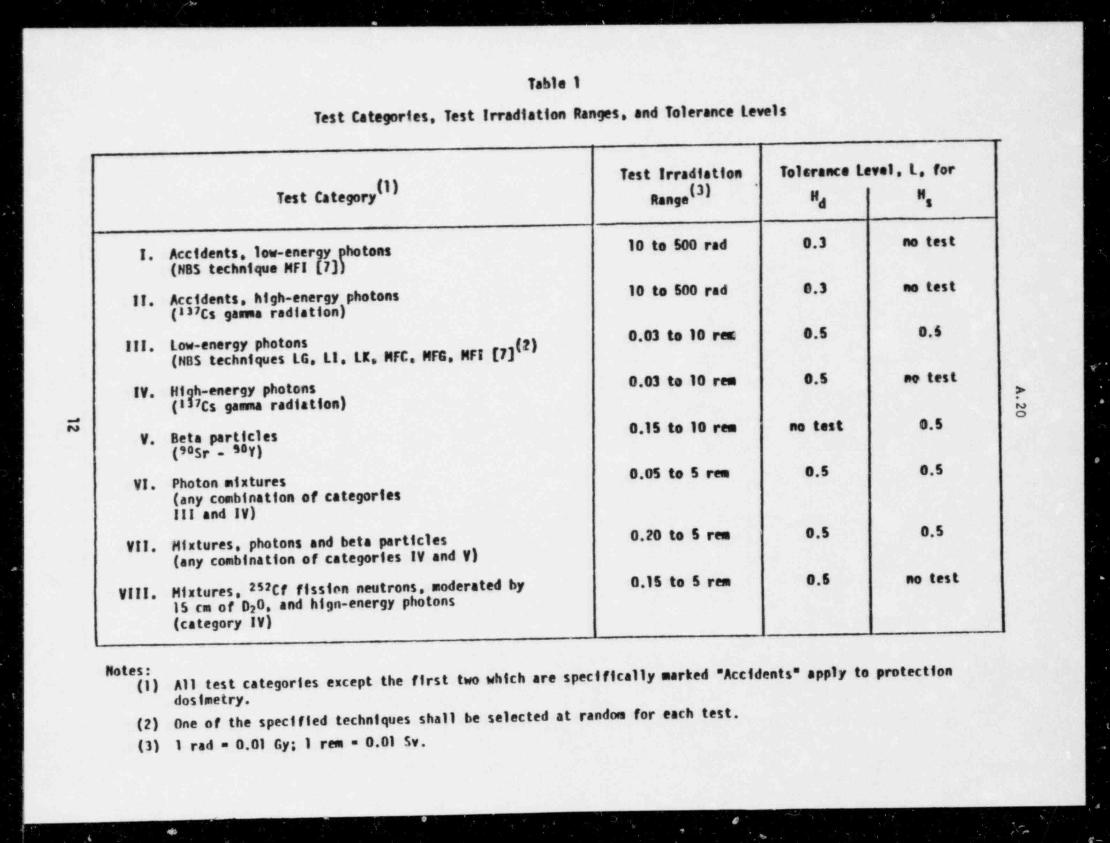
.
.- . .... .
.. .. . . . . . . . . . . _ . . . _ . . .. _
Table 1
Test Categories. Test Irradiation Ranges, and Tolerance Levels
Test Irradfation Tolsrance Level. L. forTestCategory(j) (3) , ,
*
,,
10 to 500 rad 0.3 no testI. Accidents. Iow-energy photons
(N85techniqueMFIL73)10 to 500 rad 0.3 no test
Accidents,high-energy) photons!!.(837Cs gasua radiation
0.03 to 10 rea; 8.5 0.6Low-energy photons(NBStechniquesLG.Lt.LK.MFC. MFG.MFI[7](2)III.
0.03 to 10 res 0.5 ne testIV. High-energy photons >
(137Cs gamma radiation).
a0.15 to 10 rem no test 0.5
V. Beta particles(SOSr S8 )V
0.05 to 5 rea 0.5 0.5VI. Photon mixtures
.
(any combination of categories
| III and IV)0.20 to 5 ren 0.5 0.5) VII. Mixtures, photons and beta particles
(any combination of categories IV and V)
VIII. Mixtures. 252Cf fission neutrons, moderated by 0.15 to 5 rem 0.5 no test
15 cm of D20. and hign-energy photons(category IV)
All test categories except the first two which are specifically marked " Accidents" apply to protectionNotes:(1)
dosimetry.(2) One of the specified techniques shall be selected at random for each test.(3) I rad = 0.01 Gy; I rea = 0.01 Sv.
.____
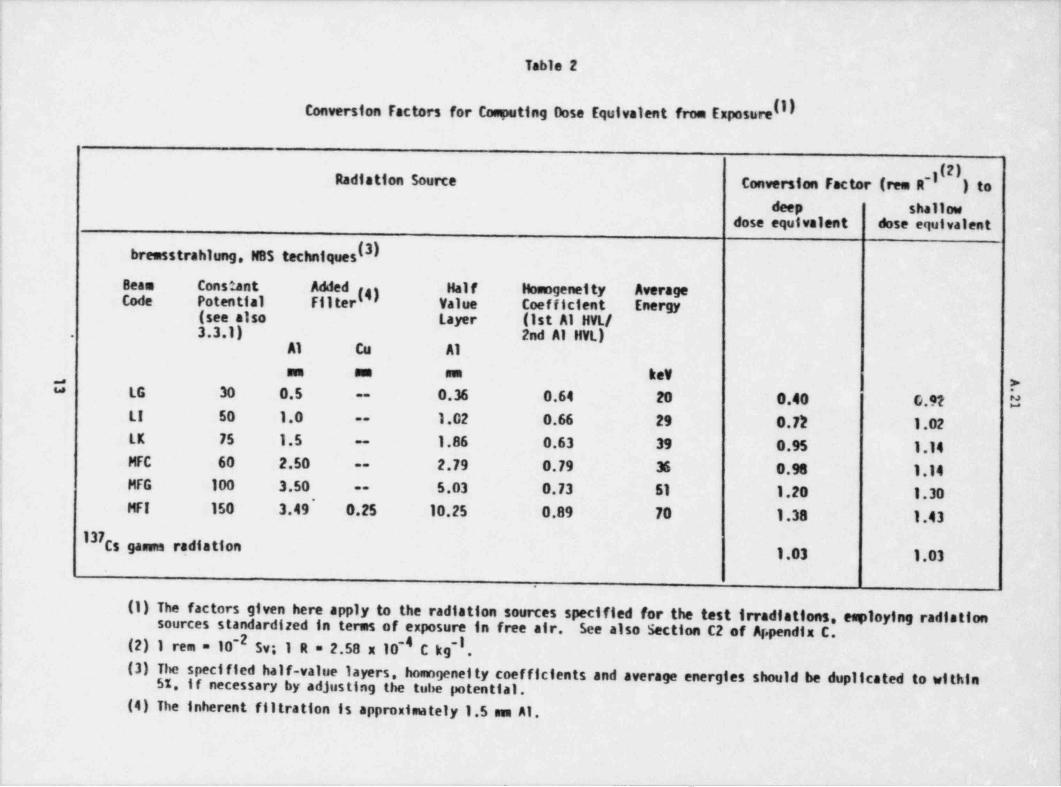
. _ _ _ . _ . _ _ _ __ _ _ _ . . _ _ . _ _ _ _ _ _ _ _ _ _ _ . _ _ _ . _ _ . _ . _ _ _ _ . _ . _ _ . . _ . _ _ _ _ . _ _._ _. _ . _ _ . _ . _ _ .
,
Tabla 2,
|
Conversion Factors for Computing Dose Equivalent from ExposureIIIi
i
i
t
Conversion Factor (ree R'y(2), Radiation Source )toi
); deep shallowdose equivalent dose equivalent
|
| bremsstrahlung. N85 techniques (3I;
t Beam ConstantAdded(4) Half Homogeneity Average
; Code Potential Filter Value Coefficient Energy, (seealso Layer (1st Al HVL/i 3.3.1) 2nd Al HVL).
! Al Cu A1
um um nun kev,
| >i U LG 30 0.5 '
0.36 0.64 to 0.40 G.92 h--
! LI 50 1.0 1.02 0.66 29 0.72 1.02--
j LK 75 1.5 1.86 0.63 39 0.95 1.14-
i MFC 60 2.50 2.79 0.79 36 0.98 1.14--
i MFG 100 3.50 5.03 0.73 51 1.20 1.30--
j MFI 150 3.49' O.25 10.25 0.89 70 1.38 1.43I37Cs gasus radiation
1.03 1.03:'
.
i (1) The factors given here apply to the radiation sources specified for the test irradiations, esploying radiationi sources standardized in terms of exposure in free air. See also Section C2 of A.pendix C.I
(2) I rea = 10-2 Sv; 1 R = 2.58 x 10'4 C kg-I .
| (3) The specified half-value layers, homogenelty coefficients and average energies should be dupilcated to withinj $1. If necessary by adjusting the tube potential.| (4) The inherent flitration is approximately 1.5 sen AI.
|
|1
_ _ - _________ ____ .
._ __
A.221
5. References to the Text
[1] . Basic Radiation Protection Criteria. Washington, D.C.: National
Council or Radiation Protection and Measurements; 1971; Report No. 39.
[2] General Principles of Monitoring for Radiation Protection of Workers.
International Cossiission cn Radiological Protection. Elmsford, N.Y.:
Pergamon Press; 1969; Publication 12.
[31 Radiation Protection Instrumentation and Its App 1tcation.
Washington, D.C.: International Comission on Radiation Units and
Meat r"-+s; 1971; Report 20.
T,4] sceptual Basts for the Determination of Dose Equivalent. l
Washington, D.C.: International Comission on Radiation Units and |
Measurements; 1976; Report 25.
[5] Instrumentation and Mohttoring Methods for Radiation Protection.
Washington, D.C.: National Council on Radiation Protection and Measure: ents;
1978; Report 57.
|[6] Radiation Quantittes and Units, Part 5, Quantities and Units for Use
in Radiation Protection. Washington, D.C.: International Cor=stssion on
Radiation Units and Measurements; 1980; Report 33.
[7] Calibration and Test Services of the National Bureau of Standards.
| Washington, D.C.: National Bureau of Standards; 1977 April; Special|
| Publication 250; Section 8.3, Appendfx.
14
. .
__
A.23
Appendices These Appendices are not a part of American National Standard
Criteria for Testing Personnel Dosimetry Performance ANSI . . .
* * 3 they are included for information only.
Appendix A|
Test Categories and Test Irradiations
A1. Types of Radiation Included in Table 1
The types of radiation included are aseng those most likely to contribute
significantly to the dose equivalant received by radiation worker in the
United States. Photons of energies above 4.67 MeV are omitted because, in
the open window area of a personnel dosimeter, they would result in photon
irradiations mixed to a significant extent with irradiation by seccndary
electrons originating in the air intervening between source and dosimeters
in amounts nrying with source spectrum and source-to-desimeter distance.
Thensal nsutrans are omitted since the total dose equivalent received by
radiation workers in most situattgns involving potential therr.a1 neutron
trradiations is relatively small [E13.2 The fint and second half-value
! layers associated with the NES bremsstrahlung techniques Itsted in category|
!!! have been specified by Nis [E2]. Corresponding photon spectra may be
obtained from NSS. For photon energies below S0 kev the converston factors
from exposure to the dose equivalent (or absorbed dose) depend strongly on
the photon spectrum; therefore, the specified bremsstrahlung generators
were restricted to thos expected to produce spectra similar to the constant
potential generator employed at NBS.4
2- Bracketed numbers refer to corresponding listings given in Appendix E.References to the Appendices.,
15
_ . _ _ -- .- . _ _ _.
- - ________
1
A.24
252The reason for specifying a Cf source for category VIII was mainly252that Cf sources a're available in a geometry in which they approximate
point sources of knswn spectral composition [D). Sch sources, used with
or without a moderator, may be readily standardized in terms of neutron
emission rates from which values of the dose equivalent per unit fluence at
the dostseter location say be computed with an accuracy depending on how
well the emission rates and the particular neutron spectra are known. For252the D 0-moderated Cf source specified in category VIII, Ing and Makra (E4]2
computed that 33 percent of the total fluence--91 percent of the dose
equivaleat--was due to neutrons above 50 kev in energy, 22 percent of the
fluence--85 percent of the dose equivalent--due to neutrons above 250 key,
and 18 percent of the fluence--78 percent of the dose equivalent--due to
neutrons above 600 kev in energy. See Appendix 8 for source standardization
and Appendix C for the interpretation of dostmeter response.
A2 Test Irradiation Ranges
The range of test irradiation levels specified in Table 1 resulted
from a compromise between considerations based on the principles of personnel
dosimetry for radiation protection recomanded by the NCRP IE5], and technical
limitations imposed by currently employed personnel dosimetry systems. The
NCRP recem. ends personnel dosimetry when the annual maximum dose equivalent
is likely to e.xceed one-fourth of the recocnended annual limtt. One-fourth
of the annual Itmit is not exceeded when all individual dosimeter readings for *
bi-wedly or icnger monitoring periods lead to dose equivalent interpretationss
Niew the lower Ifmits of the range of test levels specified fn Table 1.
One-fourth of the annual limit could be e.xceeded for weekly monitoring periods;
16
-- -. _ _ _ _ .
__ _
f
A.25i
,
however, weekly monitoring periods are not used norinally except when high dose
equivalents or excessive fading af dosimeter response are expected. Tests
of accident dosimetry are presently specified 6nly for photons. It is
suggested that participants asking to be tested in the low- and/or high-energy
photon categories in the protection range (categories III or IV) be tested
also in the corresponding accident categories I and/or II). Tests of dosimetry
associated with criticality accidents [E6] are not included in this standard.1' Considsration was given to whether it was desirable to extend the tests
to lower levels of the dose equivalent fr. view of the NCRp reconsnendation
,to limit the dose equivalent from occupational exposure to the embryo-fetus
t
of the expectant mother to 0.5 rem during the entire gestation period [E7].
It was decided that such an extension was not required because a dose
f equivalent of 30 mram, which is the lower test limit for photons in Table 1 -
(categories III and IV), is adequate for measuring a prospective value of'
:
{ 0.5 rem with monthly or longer monitoring periods.
! A3. Selection of Irradiation Levels
A suitable method for selecting irradiation levels within any one test.
category and test irradiation range would be to select random numbers, c,,
i
| between 0 and 1 from a random number table [E8], and represent the logarithm
of the dose equivalent H, asi
log (H)g + p[ log (H)g - log (H)g] .| logH =
>
where(H)g and (H)g are the lower hnd upper Itaits, respectively, of the
range of test irradiation levels in question. Random selection of the.
logarithms of the irradiation levels rather than of the levels proper
! increases the probability for the selection of values near the lower limit
| of the range.
17
.
. . - - - _ _ _ . - - . -- -1
. _ _ _ _ _ _ _ _ _ ._. . _ _
'
A.26
||
A4. Restrictions en CGmposition of Radiation Mixtures.
Restricting tM ratio of the dose equivalents of the radiation componenes *
1r. category VIII, stemning from the neutron source proper and from category IV
photons, to values not larger than 3:1 is motivated mainly by considerations
6f technical limitations with nuclear-track emulsions. This restri.', tion is.
reasonable in the light of the reconnendation of the International Comission
on Radtplogical Protection (ICAP) to use personnel dosimetry for neutrons
"only if the likely neutron dose equivalent is a substantial portion of the
gama dose equivalent, say more than about a third" [E9]. For the sake of
simplicity, the same ratio was adopted for categories VI and VII.
AS. Source-to-Dasimeter Distance
In general, the chosen source-to-phantom (or dosimeter) distance represents
a compromise between (1) irradiation-rate requirements and (2) the require. mentl
for Leeping the scattered radiation reaching the dostmeters and the phantem
from the structures of the irradiation room and from the vicinity of the source
at the lowest feasible--or at least a fixed--level. The distance limitations
in this standard resulted from such a compromise. In the case of the fission252neutrons from the 15-cm diameter D 0 moderated Cf source, these require.ments2
necessitated the specification of size, shape and composition of the phantom
and the requirement to keep the scurce-to-phantom distance fixed for all tes:
trradiations. Specifying these parameters ensures independence from considerations
of the effect on dosimeter response of deviations from the inverse-squarei
law and variations in phantori albedo, >nd independence from the choice of
an " effective" source-to-phantom distance for the different types of neutron
dosimeters whose response depends strongly on phantom albedo (albedo neutren
dostmeters).
18
c - .
_ _ _ _ _ _ _ _ _ _ _ _ _ .
. . .. . . -- . . .- -. .
A
A.27
' A6. Rationale for Use of phantos for Test Irradiations
Consideration was given to whether all test irradiations should be
carried out in the presence of a phantas. If test irradiations were performed
with the dosimeters suspended in air while, in actual use, they are carried
on the human body, a correction would have to be applied to the value (or
values) of the dose equivalent (or absorbed dose) assigned to each dosiseter,
equal to the quotient of dosimeter response with and without phantom backing.
Because of the difference of the effect of back scatter from the body (or
phantos) on different types of dostseters irradiated in different radiation
fields, this quantity would have to be measured by the tasting 1cboratory,
for each type of dosimeter submitted and for each type and energy of the test
radiation used. It was decided instead to require that all test irradiations
be made with the dosimeters backed by a phantom. No such restrictions arei
made regarding the presence or absence of a phantom during calibration.'
; (59e also Section 81 of Appendix 8.) However, for albedo neutron dcsimeters,
which of necessity are cr.librated on a phantom. it is recommended that the
processor calibrate la the test-irradiation geometry and then relate the
results of this calibration to the results of a calibration in radiation' fields of importance in actual dosimeter use. (See also Section 04 of '
. Appendix 0 for suggestions of the role of the testing laboratory in such a!
i procedure.)!
A7. Blind Testingi
In the context of testing personnel dosimetry perfor: nance, blind testing' refers to the situation in which a processor does not know which dosimeters; have been used by.a processor's personnel or customer and which, if any, have
j been irradiated by the testing laboratory which obtained these dosimeters through
the processor's personnel or customer. Test dostmeters obtained in this way
could not receive any special handling by the processor.
19
__ __ _ _. _ _ _ _ _ - _ - . -- .__ - . _ - _ - - _ _
--- - - - _ _ _ _ - _ _ _ _ _ _ _ _ _ _ _ _ _ _ ___
A.28
81tnd testing is recognized as a valuable technique for deter =ining the
capability of a processor in a realistic manner. However, there are some
inherent difficulties in providing test dosimeters without the knowledge of
i the processor, particularly in the case of in-house dostsetry operations. It
is suggested that, where feasible, some blind testing be conducted, but that
the final decision on whether or not to make bitnd testing an integral part
of the compulsory testing program be deferred until sufficient results from
blind tasts have bean accumulated to deterstne if there exist significant
differences between the performane.e on open and blind tests.
20
_ _ . _ __
;
;
!
1
i
|A.29
!
I Appendix 8j
Source Standardization
] 81. Photons!
Photon radiation fields usually are standardized in terms of exposure
; (X), a quantity related to ionization in air, measured in units of roentgens1 .1 (R). This standardi ition may be carried out either in free air or in a
| phantom. . Sf ace the quantity, dose equivalent per unit exposure at a given
{ point in a phantom, depends only little on photon energy while the quantf ty.
|. :fose equivalent per unit exposure at a given point in air varies strongly
with energy for low photon energies (see Section C2 of Appendix C), it would
be of advantage to sensure exposure due to low energy photons in a phantom
I when the photon spectrum is not well known. However, in-phantom measurement:
) require specially designed fonization chambers (E103. For this reason, most
i calibrations are perforned in free air. The conversion factors in the standardi
j and in Appendix C are given only for exposure in fres air to dose equivalent.
| For in-air measurements, a calibrated reference class (laboratory
standard) instrument may be used. This is an instrument having a performance
and stability sufficient for it to be employed in the calibration of othar!
i instruments. It is further recommended that a field exposure meter, equipped
with suitable ionization chambers, be available. This is an instrument having
a performance and stability sufficient for it to be used for routine calibration;
checks at the location of the test dosimeters to be calibrated. Its also! Appendix A. Section A6 for a discussion on how to account for the fact that,
) in actual use, the dosimeters are carried on the human body.
}t
! *1 R = 2.58 x 10 C kg*I.4
!
:
|'
21
,_ _ _ _ . - - . . _. . -_ __
- _ _ _ _ _ _ _ _ _ _ _ _ _ _ _ _ _ _ _
A.30
B2. Beta Particles
905r 90Y beta-particle beam may be standardized directly in temsThe
of absorbed dose in the phanten by means of an extrapolation tonization
chamber equipped with close to phantom-equivalent walls of variable thickness,
or by a similarly equipped fiAed-volume " thin" 1ont2.ation chamber [E11]. At
the site of the dosimeters no significant bremsstrahlung contamination of the
beta-particle beam could be detected in the setup used during the pilot-testing
program referred to in the Foreword [E12].
83. Neutrons
fleutron sources usually are standardized in terms of emission rates,
from which values of dose equivalent per unit fluence may be derived when
the neutron spectrum is known. The conversion factor, c'n.d , derived in252this way for the moderated Cf fission source specified in category VIII,
|'
does not take into account the contribution by neutrons scattered frcm
structures utraneous to the moderated source nor the contribution of the
photons originating mainly within the source. Since these corrections are
in part characteristics of room geometry rather than of the source proper,
they are best applied directly to the dose equivalents assigned to the
individual irradiated dosimete.rs. (See also Section C2 of Appendix C.)
Considerations of how to reduce room back scattering enter prominently
into any planning for an irradiation facility. A careful assessment of the
contribution of room-reflected neutrons is particularly important where it
cannot be reduced to a negligible level, which is often the case in a neutron
irradiation facility. The assessment carried out by C. Eisenhauer
of NBS using the image-saurce technique [E13] for the facility employed for
t
22
- - __ _ - _ _ _ _ _ _ _ _ _ _ _ _ _
A.31
' nevron irradiations in the pilot testing program referred to in the Foreword
to tr.is standard may be used here as an example: The rcom was 7.6 a wide and
more t un 20 m long. It had a peaked light-wight metal roof that joined
the masenry walls at a height of 3.7 m above the concrete floor. Both the2; 2Cf source within its D 0 moderating sphere and the center of thepoint
2|phantom carrying the dosimeters were at a height of 2.4 m above the floor
4
and somewh t closer to one of the longer walls of the otherwise essentially
{ empty room. For this geometry, room-reflected neutrons added 4 percent to
the deep dose equivalent computed from the ource emission data for a source-
to-phantom dis:ance of 1 m and is expected to add about one-fourth of this;
,
percentage for a 50-cm distance. Neutron scattering in the air added another
: slls percent for a 1-e distance and about one-half of this percentage for a
50-cm distance. The contribution of neutron scattering may be expected
to be considerably larger in a smaller room with more massive walls and
ceiling.
The contribution to the dose equivalent arising from the photons252
associated with the fission-neutron emission from a bare Cf source were
computed by Stoddard and Hootman [E14] and recently also have been measured bv
i several different groups. No reliable infonnation is prssently available
on the photon spectrum below %100 kev. Therefore it is not possible ati
this time to assess the contributions to the shallow and the deep dose'
equivalent separately. For the moderated source a value of 0.3 was recently
obtained by. D. Hankins of the Lawrence Livermore Laboratories by means of'
measurements with albedo neutron dosimeters for the quotient of the dose
equivalent arising from the associated photons to the neutron dose equivalent ,
(excludinij room scatter contributions).
23;
-____________ _ _ . .-_ _ -. _ -.
_ _ _ _ _ _ _ _ _ _ _ _ .
A.32
Appendix C
"Interpretation of the Response of Personnel Monitoring Dosimeters
C1. Use of the Shallow and the Deep Dose Equivalent (or Absorbed Dest)
Recorrendations have been made for the maxitun pemissible leve's of
occupational exposure to ionizing radiatici for the skin and the exuremities,
for the lens of the eye, and for the gonads and deep-seatee organt [E15]. A
direct determination of dose equivalent for each of these organs is usually
irpossible [E16], or at least impractical for routine radtation protection
measurements. In this standard, the values of the shallow and/or deep dose
equivalent (or absorbed dose to tissue) are employed to quantify the irradiation
of each test dosimeter. At present, no tests are included *or the dose
j equivalent at the nominal depth of the lens of the eye (0.., cm). The choice
of conversion factors to dose equivalent from the quantities in which the
radiation fields are usually standardized is discussed in Section C2 of this
Appendix.
It may be noted that:
(1) For photons of energies between 0.05 and 3 MeV, the maximum dose
equivalent for the majority of the incident photons is attained at a depth
less than or in the vicinity of 1.0 cm in the bed." [E17]. Therefore, the deep
dose equivalent, as a rule, is close to or overestimates the dose equivalent
to deep-seated organs. However, below %40 kev, the dose equivalent to the
lens of the eye may be underestimated by the e,eep dose equivalent by about
5 percent at $30 kev, by about 20 percent at %20 kev, and by as much as a
factor of two and more below %17 kev [E17].90 90(2) For beta particles from the specified 5r/ Y source and for photons
of energies belew %.05 MeV, the shallow dose equivalent is essentially equal
to the dose equivalent to the skin.
24
. . ___ __- _ _ _ _ _ _ _ _ _ _ _ _ _ _ _ _ _ _ _ _ _ _ _ _ _ _ _ _ _ _ _ _ _ _ _ _ _
_ _ _-
- -
A.33
252(3) For the neutrons of energies aboYe %100 kev from the Cf source
socirated by 15 cm of D 0 the maxima dose equivalent is attained in the2
vic nity of I cm in the body, for which the deep cosa equivalent is defined
in tne standard. For the lower energies, the maximum is attained at somewhat J
1arge repths in the body, ranging from 3 cm to 4 cm for neutrons of energies
betwet 10 eV and 10 kev [E183 and thus is slightly underestimated by the;
deep do e equivalent as defined. The shallow neutron dose equivalent for
which ne tests are included in the standard was calculated by C. E. Eisenhauer
of NBS to be larger by about 7 percent than the maximum neutron dose equivalent
occurring at depths 11 cm for the moderated source specified.1
i
I
i
i
t
!
li
25
L-_____- . . - . _.
-.
A.34
|i
C2 Assignment of Values of the Dose Equivalent (or Absorbed Dose)
Oose guivalent (or absorbed dose) assignment to ::asimeters irrad.ated
for test purposes is straightforward when the radiation field is stan aardized
; in terms of absorbed d6se. Ilhen this is not the case, conversion fa: tors
(additional to quality factors in the case of the dose equivalent) nually
are required for arriving at the dose-equivalent (or absorbed-desti assign-
ment from the sensured quantities. For beta particles, for which beams
usually are standardized in terms of absorbed dose at the desire.1 depth in
a tissue-equivalent phantom, the problem of conversion factors does not
arise. Following is a discussion of the choice of conversion factors,
starting with the conversion factors for neutrons, which historically
preceded those for photons.
Conversion factors for neutrons.
The conversion factors from fluence to the maximum rautron dose equiva-
1ent reconnended by the NCRP, ICRP, and ICRU [E18], [ Elf], [E20], have
been in use for many years. They are based on computa*. ions perforced by
Snyder's group at the Oak Ridge National Laboratory (ORNL) under the assump-
tion of a homogeneous cylindrical phantoa, 60 cm hig'i, having a circular
cross section of 30 cm in diameter and unit density, and containing the
elements H C N and 0. Recently, calculations also have been perforsned
[E21] for the ICRU 30-cm diameter spherical phants [E223
The value for the conversion factor c*n'g f rom fluence to dose equiva-7521ent given in this standard for the moderated Cf source was cceputed1
by C. Eisenhauer of NBS by weighting the flue sca-to-dose equivalent con-
in.d(E), recommended by the NCRP [E183--with additionalversion factors, c
points interpolated on the logarithmic scale--by the neutron fluence
spectrum e (E) given by Ing and Makra [E4] asn
26
_ _ _ . _ _ _ _- __ . . .._ - - _-
- - - _____-
A.35
I E,,,sax
$,(E)c$.d(E)dE/ $,(E)dE .c ",
1.0 eV 1.0 eV
|where the expression in the eenominator is the neutron fluence. The
unce-tainty in this value is considered to be of the order of 210 percent,
reflecting the uncertainty in the fluence spectrum.
For assigning a dose equivalent to the desimeters irradiated with252neutrons from the moderated Cf fission source specified for test cate-
gory VIII. a value of 0.3 is suggested for the quotient of the associated
deep photon dose equivalent and the neutron dose equivalent. This value
does not contain the contribution from room-scattered photons. See also
Section 83 of Appendix 8.
Conversion factois for photons,.
The choice of conversion factors was difficult in the case of photons,
because it has been customary in the past to simply equate the numerical
values of exposure and dose equivalent (or absorbed dose) for protection
purposes. Yet, early ICRP recomendations [E19] for conversion factors
based on ionization measurements of Delafield at Harwell in an elliptical
water phantom irradiated with filtert:d bremsstrahlung have existed for
some time. More recently, the American National Standards Institute
published recomendations. mainly for application in shielding computations,
of conversion factors from fluence to the maximum dose equivalent [E23].
These recomendations are based on computations by the discrete ordinate
27
_ _ . . __
A.36
method carried out by Claiborne and Trubey of ORNL for moncenergetic photons
incident perpendicularly on a semi-infinite slab of tissue containing
traceelements[241.*
During ttu past 15-20 years. a relatively large body of protection-
oriented work, involving both computations and experimen . has accumulated-
[E17.E23 E25-E30]. Not all of it is in published fom. The results are
difficult to compare mainly because of differences in the shape and com-
position of the chosen phantoms (cylinders, slabs, spheres; ' tissue" con-
taining the elements H. C. N and 0 with and without added trace elements;
unidirectional or isotropic radiation incidence; focus either mainly on
maximum values of dose equivalent--or absorbed dose--or on values at
specific depths).
From the start, the Workgroup had decided on data for unidirectional
radiation incidence, and on the use of two irradiation depths reflecting
irradiations of the skin and of deep-seated organs. The choice of uni-
directional radiation incidence ensures that if the test dosimeters (whose
response may strongly depend on the direction of radiation incidence) had
been worn by a worker, the dose equivalent assigned tc the dosimeters in
general would overestimate tha effective dose equivalent [E313 to the
worker in any arbitrary fixed or variable orientation in an isotropic
radiation field [E323. The choice of assigning skin and deep-seated
organ dose-equivalent (or absorbed dose) satisfies only partially ths
requirements of the Nuclear Regulatory Comission [E333. This is the case
because, for radiation incidence from a source facing a worker, the dose
*This work has been recently updated through supplementary Monte-Carlo
calculations performed by C. S. Taoia in Trutey's group at ORN'.. The
results are as yet not available in published fom.
28,
_ . -_--__-
..
A.37
equivalent (absorbed dose) to the leness of his eyes, located at a nominal
depth of 0.3 cm, may be underestimated below 40 key when obtained as oeep
doseequivalent(absorbeddose). (SeealsoTableCZ.) Wyertheless.
it wes decided to restrict the test procedure to two depths (0.007 cm
and 1.0 cm), at least initially.
In the N13.11 draft published in 1978, conversion factors based on the
ICRP recommendations [E19] augmented at low energias by factors cor:puted'
for the Workgroup by T. D. Jones of ORftL for parallel moneenergetic photon
beams incident on the Medical Internal Radiation Dose (MIRD) phantom were '
used. Later, when the results of new computations and measurements became
available the Workgroup decided to review its position on the choice of
such parameters as phantom gecmetry and phantom compas4 tion, taking into
account tne scientific merit of the recent results and the current
recommendations for assessing the maximum dose equivalent. (See,e.g.,
ICRP Publication 26 [E31].)
Eventually, the considerations narrowed down to a body of work*
[E17,E34,E35] carried out mainly with Monte-Carlo calculations for parallel
moncenergetic photon beams incident on the four-element ICRU sphere [E22]
and the reasurements carried out by reans of art e.xtrapolation char.ber
; incorporated in a slab phantom of a " tissue-equivalent" plastic with137incident beams of K fluorescence and Cs photons *[536]. Although they
*
It was decided to eliminate the slab data from Trubey's group at OR!il [E23]
from further consideration, even after they had been updated by C. S. Tapia.
These data differ materially from the experimental data of Yoder et al
[E36], which agree reasonably well with the results of ccmputations carried
out by A. 8. Chilton of the University of Illinois under the auspices of
an ICRU workgroup. (Some of the differences can be explained qualitatively
by the difference in phantom composition.)
29
_____ _ _ _ . .-
- -- . _ _ _ _ _ _ _ _ .
! A.38
do not all incorporate the same assumptions, there is relatively good
agreement among the , computations of the different groups carried out for
the ICRU sphere, which were also supported t;y measurements with ther .o-
luminescence dostmeters, using filtared bremsstrahlung [E35.E37]. The
most corslete readily available set of data for a range of different depths
in the sphere is that of Dimbylow and Francis [E17]. These data may de
considered somewhat more reliable than the data computed by others because
the motion of the secondary electrons was followed down to 80 kev while
the others assumed electron absorption at the point of production.
The following factors entered into the considerations on whether to
use in the standard the conversion factors staming from the Dimbylow and
Francis computations or those steming from the experiments of Yoder et al:
(1) The choice of a spherical or slab-type phantom is somewhat arbitrary,
since neither of them represent the human body in detail. The conversion
factors derived for the spherical phantom are expected to he 3ccewhat lower
than those derived for the slab phantom (particularly when irradiated with
divergent beams [32(b)3). but both are high compered to what they would have
been under the assreption of isotropic radiation incidence and thus lead
to an overestimation of the dose equivalent. (2)Whiletheplasticphantom
used by Yoder et al was supposed to simulate tissue with trace elements
(E24), the total energy absorption coefficient calculated for the plastic
phantom for photon energies over the entire range covered by the tests are
at most -to-3 percent higher than those for four-element tissue, while those
of the tissue with trace elements are up to 11 percent higher. Thus results
for conversion factors obtained for bona fide tissue with trace elements
were not available. (3) Only one measurement was made so far by Yoder
et al for any depths other than 0.007 and 1.0 cm, while ccmputed values
30
_ _ _ _ _ _ _ - _ _ . ._ _ _ _ _ .
A.39
are available over a range of depths, including 0.3 cm, the depth of the
eye lens, and for the dose equivalent index. (4) The ICRU presently is
' working on further recomendations regarding the application of the maximum
dose equivalent (the dose equivalent index) to practical protection
dosimetry. The dose equivalent index however is defined for the ICRU sphere*
only. Based on these considerations, it was the consensus of the Workgroup
to specify the conversion factors of Dimbylow and Francis. This decision
does not reflect a value judgment on the relative scientific merit of the,
two sets of data between which the final choice was made, but only on their
utility for the present app 1tcation.
! Under the assumption that the majority of U.S. users calibrate in'
tems of exposure in free air, values of conversion factors are given in
Table 2 of the standard for obtaining the shallow and the deep dose equiva-
lent from exposure for the photon spectra specified for the test frradt-;
'
ations. These values were obtained as weighted averges of the correspond-
ing conversion factors, c ,s(E) and cX,' (E) shown in T4 ble C2 for theX d
| depths of 0.007, 0.3 and 1.0 cm in the ICRU sphere, irt adiated with ad
unidirectional (parallel) beam of moneenergetic photons. For each NBS
technique specified, the weighted average was computed ashx { hx
c (E) e h(E) u",[(E) E dE / Jeh(E)uj[(E)EdE,c =x y p p
o o
The conversion factors [E203 from neutron fluence to the maximum neutron'
dose equivalent which are new in general use were computed for a cylindrical
phantom. Their computation antedates the femal definition of the maximu=
dose equivalent.,
s
'
31
. _ . _ _ _ _ . . . . _ _
- ___ - _________ __ __
A.40
where 9ph(E) is the fluence spectrum obtained [E383 from measured pulse-
height distributions for the particular technique over the pertinent range
of photon energies E, and u*en (E) is the mass energy absorption coefficient
of air [E39]. The upression in the denominator is the exposure.
Inasmuch as, up to 150 kev, the maximum of the dose equivalent (for-
this geometry equal to the " dose-equivalent index") is reached at a depth
in tissue comparable to 0.007 cm (the maximum range of the Compton electrons
produced by a 150-kev photon being about 0.005 cm) the values computed by
Dimbylow and Francis for the dose-equivalent index were used for cX,d(E)
in this range. The values of eX(E) for the 0.3-cm depth, teportant for
assessing the dose equivalent to the lens of the eye, are seen to be higher
than those for the 1.0-cm depth for photon energies below 50 kev. . For
higher photon energies, the calculations do not reveal a significar.t
difference between the conversion factors for these two depths. Therefore ,
for photon energies 150 kev, identical values are shown in the table. In
fact,in order to irgrove the statistic, the values for ct.d(E) for
E 150 kev were obtained by averaging the data for the depths fecm 0.3 to
1.0 cm, which do not show a trend with depth. The relative standard deviation
of the individual data from their maan was at most 2 percent. TheI
fluctuations indicated by the authors for the individual data points lie
between 3 and 4 percent.137
| For Cs gama radiation (662 kev), for which the shallow depth does
not provide for electron equilibrium in tissue, the quantity measured
(exposure,doseequivalent,absorbeddose)atapointofinterestatthis
depth depends on the charged-particle fluence reaching this point from the
surroundings. In this case, it is impossible to define a generally valio
r
32
-
A.41
|
correlation between esposure and absorbed dose or aose equivalen:. For the
present application the values for cy,3 and c d were arbitrarily set equalXI37
for Cs gama radiation, which implies the presence of charged-par.f ele
fluence from tissue in the innediate surroundings.
I
,
f
33
_ _ _ - - - - _--
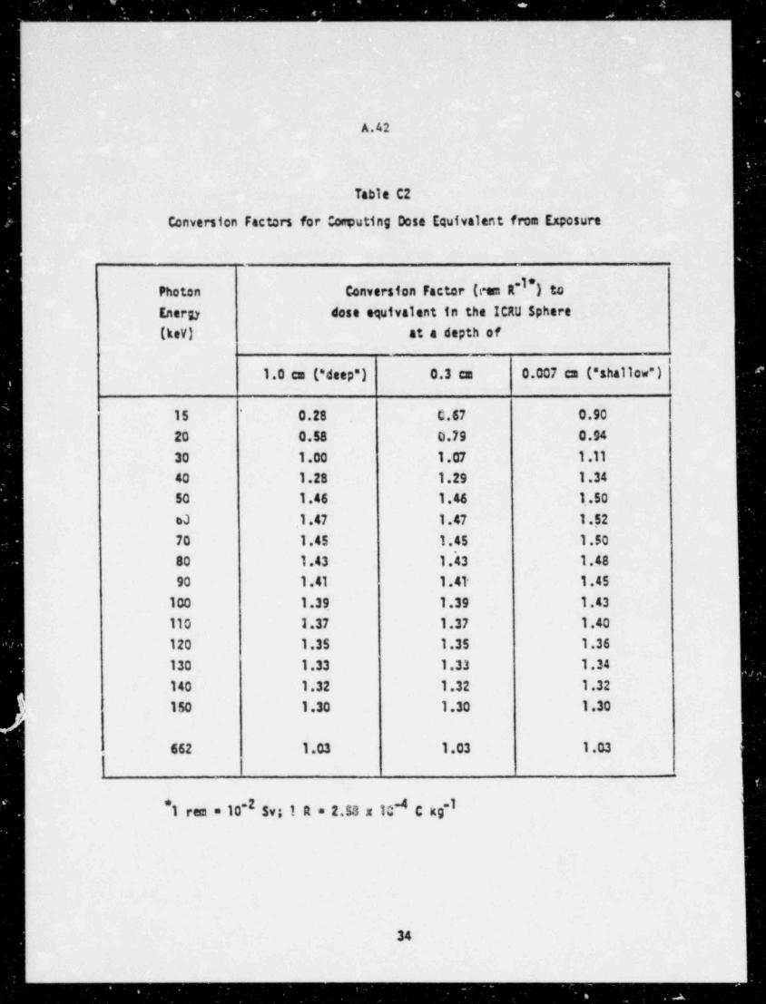
._ _ _ _ _ _ _ _ _ _ _ _ _ _ _ _ _ _ _ _ _ _
A.42
Table C2
Conversion Factors for Conputing Dose Equivalent from Exposure
Photon Conversion Factor (com R~I*) toEnergy dose equivalent in the ICRU 5phere
(kev) at a depth of_.
1.0 cm (* deep") 0.3 cm 0.007 cm (" shallow")
15 0.28 C.67 0.90*
20 0.58 0.79 0.94
30 1.00 1.07 1.11
40 1.28 1.29 1.34
50 1.46 1.46 1.50
oJ 1.47 1.47 1.52
70 1.45 1.45 1.5080 1.43 1.'43 1.48
90 1 .41 1 .41- 1.45
100 1.39 1.39 1.43
110 1.37 1.37 1.40
120 1.35 1.35 1.36
130 1.33 1.33 1.34
140 1.32 1.32 1.32
150 1.30 1.30 1.30.
662 1.03 1.03 1.03
*1 rem = 10-2 Sv; 1 R = 2.53 x 10 C kg-l4
34
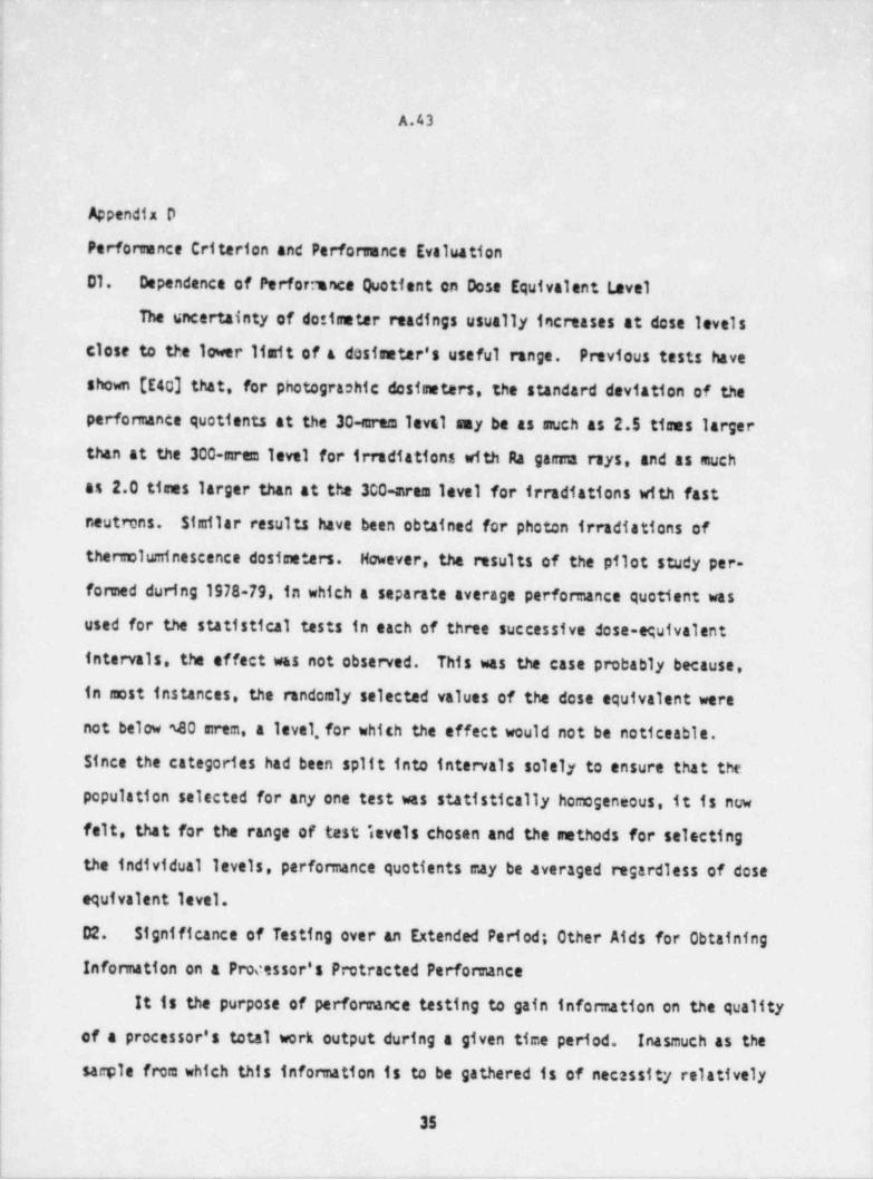
___
M
A.43
: !';
i
Appendix D.1
; Perfonrunce Criterion and Perforsunce Evaluation
j D1. Dependence of Perfor:ance Quotient on Dose Equivalent Level
i The uncertainty of dosimeter readings usually increases at dose levels
! close to the lower limit of a dosimeter's useful range. Previous tests have
| shown (E40] that, for photograohic dosimeters, the standard deviation of the
performance quotients at the 30-erem level my be as much as 2.5 tisms larger-
i than at the 300-arem level for irradiations with Ra garma rays, and as much
f as 2.0 times larger than at the 300-aram level for irradiations with fast
. neutmns. Similar results have been obtained for photon irradiations ofi
| thenroluminescence dosimeters. However, the results of the pilot study per-
formed during 1978-79, in which a separate average performance quotient was
j used for the statistical tests in each of three successive dose-equivalent1
intervals, the effect was not observed. This was the case probably because,
in most instances, the randomly selected values of the dose equivalent were!
i not below 40 mrem, a level, for which the effect would not be noticeable.
Since the categories had been split into intervals solely to ensure that the'
population selected for any one test was statistically homogeneous, it is now
| felt, that for the range of test invels chosen and the methods for selecting
the individual levels, performance quotients may be averaged regardless of dose'
| equivalent level.i |
| D2. Significance of Testing over an Extended Period; Other Aids for Obtaining i|
Information on a Processor's Protracted Performance i
It is the purpose of performance testing to gain infonnation on the quality
of a processor's total work output during a given time period. Inasmuch as the
samle from which this information is to be gathered is of necessity relatively
35
_ _ _ _ . - -_ _ . __ -- _ _ _
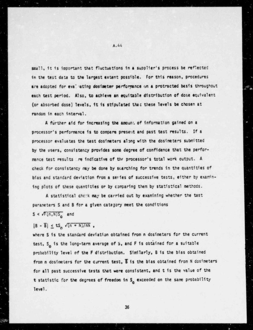
.- _ _ _ _ _ _ _ _ _ _ _ _
i
A.44
small, it is important that fluctuations in a supplier's precess be reflected
in the test data to the largest extent possible. For this reason, precedures
are adopted for eva?tating dosimeter perfortrance ten a protracted basis throughout
each test period. Also, to achieve an equitable distribution of dose equivalent
(or absorbed dose) levels, it is stipulated thac these levels be chosen at
random in each interval.
A further aid for increasing the amount, of information gained on a
processor's performance is to compara present and past test results. If a
processor evaluates the test dosimeters along with the dosimeters submitted
by the users, consistency provides some degree of confidence that the perfor-
ance test results :.re indicative of the processor's total work output. A
check for consistency cay be done by st. arching for trends in the quhntities of
bias and standard deviation from a series of successive tests, either by examin-
ing plots of these quantities or by comparing them by statistical metheds.
A statistical che:k may be carried out by examining whether the test
parameters S and B for a given category meet the conditions
S < /f(n,N)So ""d
|B - T| < tS, /(n + N)/nN ,,,,
where S is the standard deviation obtained from n dosimeters for the current
test, S, is the long-term average of 5, and F is obt'ained for a suitable
probability level of the F distribution. Similarly, 8 is the bias obtained
from n dostmeters for the carrent test, Iis the bias obtained from N dosimeters
for all past successive tests that were consistent, and t is the value of the
t statistic for the degrees of freedom in 5, exceeded on the same probability
level.
36
__
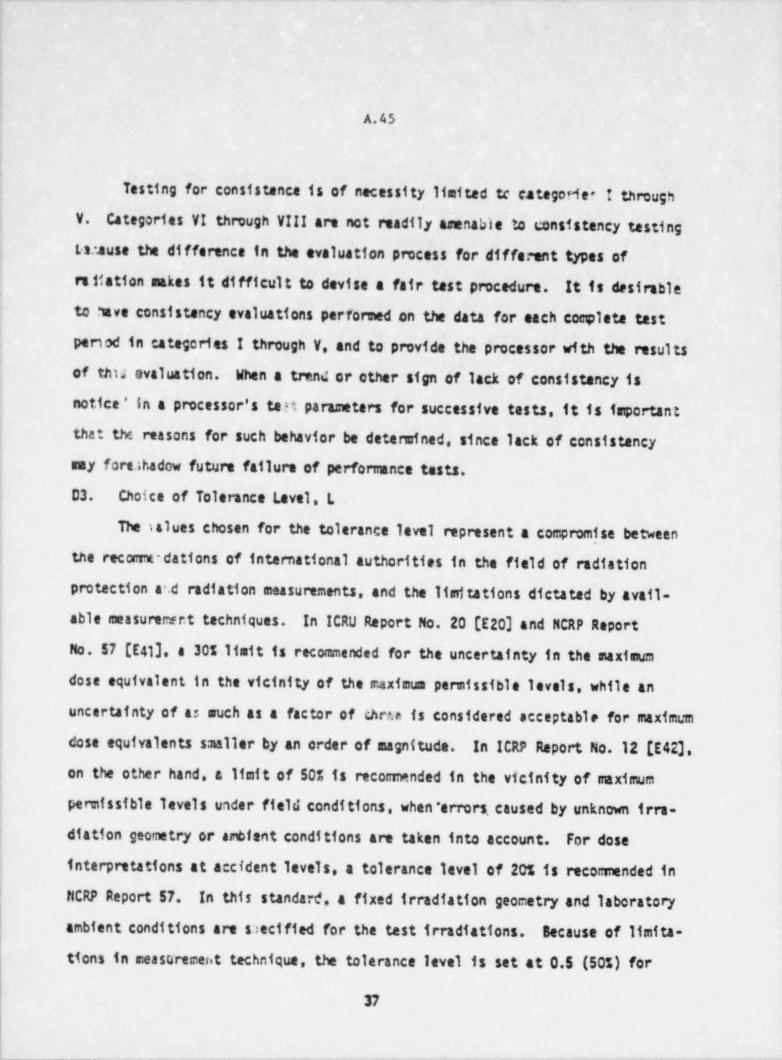
_.
!
:
!
A.45
Testing for consistence is of necessity limited tc categorier I through! V. Categories VI through VIII are not readily amenable to consistency tasting
Lat.ause the difference in the evaluation process for different types of
re ttation askes it difficult to devise a fair test procedure. It is desirable
to have consistency evaluations performed on the data for each complete testi
.
period in categories I through V, and to provide the processor with the results
of this evaluation. When a trend or other sign of lack of consistency is:
i notice ' in a processor's tatt parameters for successive tests, it is important
f that the reasons for such behavior be determined, since lack of consistencyI say fort.thadow future failure of performance tests.
j D3. Choice of Tolerance Level, L
! The salues chosen for the tolerance level represent a compromise between
I the reconmdations of international authorities in the field of radiation
protection a .d radiation measurements, and the limitations dictated by avail-
able measuremer.t techniques. In ICRU Report No. 20 (E20] and NCRP Report
{ Mo. 57 (E41], a 305 Ifmit is recommended for the uncertainty in the maximum
dose equivalent in the vicinity of the maximum permissible levels, while an
; uncertainty of as such as a factor of thru is considered acceptable for maximum
dose equivalents smaller by an order of magnitude. In ICRP Report No.12 [E42],:
; on the other hand, a limit of 50% is reconanded in the vicinity of saximumi
pennissible levels under field conditions, when * errors, caused by unknown irra-
diation geometry or ambient conditions are taken into account. For dose
interpretations at accident levels, a tolerance level of 205 is reconinanded in
| MCRP Report 57. In this standan*, a fixed irradiation geometry and laboratory|
| ambient conditions are saecified for the test irradiations. Because of limita-
tions in measurement technique, the tolerance level is set at 0.5 (50s) for
37
_ _ _ _ ._- .. . - - - - . . . _ . -. _- _ _ . . . _
_ _ _ - _ _ _ .
A.46
all but the accident categories and the high-energy photon categories, where
it is set at 0.3 (37.)- Larger tolerance levels for dose equivalents
well pelow the ma.ximum permissible dsse equivalent were considered and in
fact had been incorporated in the first version of this standard. Subsequent
to the experience gained in the pilot-tasting program referred to in the
Foreword, this feature was deleted since for the tests specified in thi,
standard (calling for' irradiation in relatively straightforward radiation
fields under ideal laboratory concitions and evaluation of perforranca frem
average errors obtained over a large range of dose equivalents) relacation
of the tolerance levels was found to be unnecessary.
D4. Sources of Uncertainty Not Included in the Performance Evalua: ion
This standard does not include provisions for testing a supplier's
perfomance under the various possible conditions of practical use of the
personnel dosimeters. Among the comon source; of uncertainty .ict included
are:
(1) Dependence of dosimeter response on radiation energy for a given
type of radiation and geometry of radiation incidence.
(2) Dependence of dosimeter response on angle of radietion incidence for
different types of radiation and different radiation enerries.a
(3) Dependence of response on ambient temperature, including storage
temperature before, during, and after irradiations, up *.o the time of
processing or readout.
(4) Dependence of response on ambient humidity, including s*arage
i.umidity, befont, during, and after irradiation, up to the time of processing
or nadout.
(5) Tied intervals between dostmeter issue, d rradiation, and processing
or readout.
38
.______________________ . _-
_ _ _ _ _ _ __
,
A.47,
1
| *
(6) Dependence of response on visible and ultraviolet light prior to,
i during, and after irradiation, up to the time of processing or readout,i
: (7) Position of the badge on the human body relative to the point of
maximum irradiation on the body surface, and relative to the location of the
| organs of interest.
! (8) A possible bias in the performance on an open test, that is, a test 1
5 carried out with the knowledge of the processor, introduced by the processor's
awarenes's of being tested.
The extent to which any one of these factors may contribute to a given
interpretation of dosimeter responsa varies widely, depending on dosiceter
design, processing and readout techniques. It is suggested that the testing
laboratory be in a position to evaluate the supplied dosimeter designs for the
influence on interpretation of dostmeter response of any of these and other
factors (such as, e.g., in the case of albedo-neutron dosimeters, dose
equivalent assignment based on source-to-phantom rurface distances as compared;
; to assignment based on the distance between the source and the orfgin of the
bulk of the thermal and/or, epithennal neutron albedo). Methods for carrying
out some of the required test procedures may be found in the literature [E433
Because of the magnitude of the potential errors associated with angular
dependence of dosimeter response, consideration was given to incorporating
into the standard performance requirements related to response characteristics
e r test dosimeters as a function of angle of radiation incidence for differenti
n.itation energies and types of radiatioc However, an adequate data base,
for the angular dependence of the response of the different types of personnel!
i
; dos neters irradiated on a phantom was not available. Therefore, it was,
.
j
39
__ _
-. _ _ _ - _ _ _ _
A.48
is:possible to select appropriate perfomance criteria. It was decided to
include requirer:ents in the standard for the development of such a data base
so that, in futum reviews and revisions of this standard, suitable performance
criteria can be specified. A procedure for determining the dependence of
desireter response on the angle of radiation incidence is suggested in Section 05.
|
|
40
_ _ _ _ - _ _ _ - _ _ ___ _-- - - --
d
_
A.49^
-
05. Measurement of pependence of On-phantom Dosimeter Response on Angle of
Radiation Incidence
Following is a suggested seasurement procedure. Another procedure was
recently published by the International Standards Ofganization (E43]. i
Irradiations are carried out with the dosimeters mounted on the phantom
used for all other test irradiations, for each radiation type and energy range___
included in the categories of Table 1 of this standard for which the dosimeters
are used by the particular processor.
Mixed radiation categories are excluded. Angle of incidence is varied in
two planes perpendicular to each other and to the plane of the dosimeter in *
contact with the phantom. At least seven different angles of incidence from
-85 to +85 degrees, and including zero degrees (perpendicular incidence), are1
used in each of the two planes. Irradiations are made with at least three
different radiation spectra in category !!!. At least two dosimeters are
irradiated identically. Values for the dose equivalent for each irractation
condition are selected from between 300 and 600 mram for photons and beta
particles, and from between 500 and 1000 mrem for neutrons. They are determined
for perpendicular incidence of the radiation on the phantom by the methods
outlined in the standard for deepand/or shallow dose equivalent, as required-
for the particular type of radiation. Dosimeter response for any angle of
radiation incidence and any type and energy of the incident radiation then is
given by the quotient of the dosimeter reading for these irradiation conditions
and the dose equivalent for perpendicular radiation incidence.
.
5.=
41^
_
TM7
-m .. ..
"- .
.
2
-
.
<#A.50
7Appendiz E
References to the Appendices-
[E1] See, for example, Becker. K. Praitsinary Results of the 1975-
-
International Personnel Monitoring survey. U.S. Department of Comerce. .
National Technical Information Services;'1975; ORNL-TM-5102. h[E2] Calibration and Test Services of the National Bureau of Standards.
Section 8.3, Appendix, special Publication 250, National Bureau of Standards, _
Washington, D.C. 20234; June 1981. -'
[E3] Grund1 J. A.; Spiegel. V.; Eisenhauer. C.M.; and others. A Cali-
fornium-252 Fission Spectrura Irradiation Facility for Neutron Reaction
Rate Measurerents. NucLess Techno4agy 32:315; 1977.
[E4] Ing, J.; Makra, S. Compendium of Neutron Spectra in Criticality
Accident Oosimetry. Vienna, Austria; International A:omic Energy Agency; _
1978; Technical Reports Series 180.
[E5] See, e.g., Basic Radiation Protection Criteria. Washington, D.C. _'
National Council.on Radiation Protection and Measurements; 1971; Report~
No. 39; paragraph 219.
[E6] American Naticnal Standard Dosimetry for Criticality Accidents.'
| ANSI N13.3-1969. American National Standards Institute,1430 Broadway,
New York, N.Y. 10018. ;--
[E7] Basic Radiatto.1 prottetton Criteria. Washington, D.C.: National
Council on Radiation ?rotection and A surements; 1971; Report No. 39;_
paragraph 240.
[E83 See, e.g., The Rand Corporation. A Million Randem Pigits wid -
100 000 Noamt Ocv4:tc4. Glencoe Ill.: Free Press Publishers; 1952.__
42 -
h-._
- . . . . _ .-
A.51
[E9] General Principles of Monitoring for Radiation Protection of Workers.
International Cosnission on Radiological Protection. Elmsford. N.Y.:
Pergamon Pr.ess; It69;. Pub 11 cation 12; paragraph 82.
[E10] For a discussion of suitable sensurement techniques see, e.g..
; Measurement of Absorbed Dose in a Phantom Irradiated by a Single team of
X or Gasma Rays. Washington, D.C.: International Commission on Radiation
Units and Measurements; 1973; Report No. 23.
[E11] For a discussion of suitable sensurement techniques, see. e.g..
Radiation Dostmetry: Electrons with Initial Energies between 1 and 50 MeV.
Washington. D.C.: International Comission on Radiation Units and Measure-;
: ments; 1972; Report No. 21.!
[E12] Plato. P.; Hudson. G. Perfomance Testing of Personnel Dostmetry.
!
Services. Supplementary Report of a Two-Year Pilot Study. Oct. 77 -
! Dec. 79; NUREG/CR-130. Division of Technical .Information and Document1'
control; U.S. Nuclear Regulatory tommission; Washington D.C.; 1980.
[E13] Eisenhauer C. as. An Image Source Technique for Calculating Reflection.
! of Gama Rays and Neutrons; Health Physics 11, 1145; 1965.
[E14] Stoddard. D.H.; Hootman. H. E. 252Cf Shielding Guide. Dak Ridge.
| Tenn.: Te:hnical Information Division; 1971; TLO-450. OP-1245. UC:'1.
[ 15] See, e.g.. Review of the Current State of Radiation Protection ;
} Philosophy. Washington, D.C.: National Council on Radiation Protection!; and Measurements; 1975; Report No. 43; Appendices A and S.
| [E16] Conceptual Basis for the Determination of Dose Equivalent. Washing-
ton, D.C.: International Comission on Radiation Units and Measurements;
i 1176; Report No. 25.<
I
i
|
.
. - -
- _ _ _ _ _ _ _ _ _ _ _ _ _ _ _ _ _ .
A.52
[E17] Diabylow, P.J.; Francis, T. M. A Calculation of the Photon Depth-
Dose Distributions in the ICRU Sphere for 6 Broad Parallel team, a Point
Sourca and an Isotropic Field; 1979; Mation41 Radiological Protection
Board, MRPB-R 92, Narwell, England.
[E18] Protection against Neutron Radiation. Washington, D.C.: National
Council on Radiation Protection and Measurements; 1971; Report No. 38.
[E19] Data for Protection against Ionizing Radiation from External Sources:
Supplement to ICRP Publication 15; International Coc:nission.cn Radiological
Protection. E1=sford, N.Y.: Pergamon Press; 1969; Publication 21.
[E2D] Radiation Protection Instrumentation and Its Application. Washington,
D.C.: International Comission on Radiation Units and Measurements; 1971;
Report No. 20.
[E21] Chen, S-Y; Chilton, A. 8. Calculation of Fast Neutron Depth-Dose in
the ICRU Standard Tissue Phantom and the Derivation of Neutron Fluence-to-
Dose Index Conversion Factors. Rad. Res. 78: 333; 1978.
[E22] See, e.g., Radiation Quantities and Units. Washington, D.C.: Inter-
national Comission on Radiation Units and Measurements; 1980; Report 33.
[E23] American National Standard, Neutron and Gam.a-Ray Flux-to-Dese-Rate
Factors, ANSI /ANS-6.1.1-1977 (N666). American National Standards Institute,
1430 Broadway, New York, N.Y.10018. See also Claiborne, M. C.; Trubey, D. K.
Dose Rates in a Slab Phantom from Moncenergetic Gama Rays; Nucl. Appl.
Technol. 8: 450; 1970.
[E24] For t'he tissue cceposition, see, e.g., Report of the Task Group on
Reference Man; ICRP Pubitcation 23; International Comission on Radiological
Protection; New York: Pergamon Press; 1976.
44
- - - - - - _ - _ - - - - _ _ _ _ _ - _ _ _ _ _ _ _ _
- .
A.53
[E 53 Delafield. H. J. Sarsaa-Ray Exposure Measurements in a Man Phantom
Related to Personnel Dorimetry.1963; AERE-R4430 Nanve11. Atomic Energy
Research Establishment.
[E26] Jones. A. R. Measurement of the Dose Absorbed in Variou:: Organs as
a Function of the External Gamma Ray Esposure; 1964; AECL-2240. Chalk River.
Ontario.
[E27] Delafield. N. N. Gasuna Ray Exposure Measurements in a Man Phantom
Related to Personnel Film Dostaetry. Phys. Med. Biol. 11: 63; 1966.,
[E28] Jones. A.R. Proposed Calibration Factors for Various Dosimeters at-
Gifferent Energier. Health Physics 12: 663; 1966.
[E29] Jones. T. D.; Auxier J. A.; $nyder. W. 5.; Warner. 8. G. Dose to
Standard Refarence Man from External Sources of Moncenergetic Photons.
Health Phys. 24: 241; 1973.,
[E30] D'Brien. K. Fluence-and Exposure-to-Dose Conversion Factors for
Human Whole-Body Ganuna Irradiation. Nealth ' Phys. 35: 494; 1978.
[E31] For the concept of " effective dos,e squivalent" (or dose) see, e.g.,
Jacobi. W. The concept of the Effective Oose--A Proposal for the Combination
of Organ Doses. Radiat. Environ. Biophysics 12: 101; 1975. For reconcended
limits, see Recomendations of the International Comission on Radiological
Protection.1977; ICRP Publication 26; International Comission on
Radiological Protection; Pergamon Press. New York *
[E32] See, e.g.. the exchange of ideas covered in (a) 0'Brien. K. The
Application of the Dose-Equivalent Index to the Natml Radiation Background.
Health Phys. 35: 506; 1978; (b) Kramer. R.; Drexler. G. The Dose-equivalent
Index (DEI) as a Function of Angular Distribution of Photons. Health Phys.
38: 427; 1980; and (c) 0'Brien. K. Reply to "The Dose-Equivalent Index (DEI)
as a Function of Angular Distribution of Photons." Health Phys. 38: 428; 1980.
45 |.
!
|
. _ _ _ _ _ _ _ _ _ _ _ _ . _ _ _ - - - - - - - . _ -
- - - - -- . - _ _ _ _ _ _ _ _ _ _ _ _
t
A.54
[E33] See e.g., instructions to Form NRC-5, Current Occupational EAternal
Radiation Exposure. June 1977; Otractor Office of Management Infonnation
and Program Control, U.S. Naclear Regulatory Connission; Washington. 0.C.
20555.
[E343 Kramer, R. Emittlung von Konversionsfaktoren zwischen Koerperdosen
und relevanten Strahlungsgroessen bei externer Roentgen-und Gama lestrahlung.
GSF-Bericht-5-55E; 1979; Gesellschaft fuer Strahlen-und Unveltforschung abH,
Neuherberg/Muenchen.
[E15] Hohlfeld, K.; Grosswendt, 8. Conversion Factors frem Absorbed Dose in
Air to Dose Equivalent Quantities for Photon Radiation. In press.
[E36] Yoder, C.; Bartlett, W. T.; et al. Confinnation of Conversion Factors
Relating Exposure and Dose-Equivalent Index Presented in ANSI N13.11.
NUREG/CR-1057; PNL-3219; 1979; Pacific Northwest Laboratory, Richland,
Washington 59352.
[E37] Grosswendt, B.; Hohlfeld, K. Title to be furnished later. In press?
[E38] Seelentag, W. W.; Panzer, W.; Drexler, G.; et al. A Catalogue of>
Spectra for the Calibration of Dos *emeters. GSF Bericht 560; 1979;
Gesellschaft fuer Strahlen-und-Uc:weltforschung mbH, Neuherberg/Muenchen.
[E39] Hubbell. J. H. Photon Mass Attenuation and Mass Energy-Absorption
Coefficients for H. C. H. O. Ar, and Seven Mixtures from 0.1 lev to 20 MeV.
Radiation Research 70: 58, 1977.
[E40] See, for example, Unruh, C. M.; Larson, H. V.; Beetle, T. H;
Keene, A. ft. The Establishment and Utilization of Film Dosimeter Perfomance
Criteria. Richland Wash.: Battelle Memorial Northwest Laboratory; 1967;
BtNL-547 UC-48.
46
_ _ _ _ _ _ _ _ _ _ _ _ _ _ _ _ - _ _ _ _ _ _ _ _ _ _ _ _ _ _ _ _ _ _ - _ _ _ _ _ _ _ _ _ _ _ _ _ _
A.55
[E41] Instrumentation and Monitoring Methods for Radiation Protection.
Washington. 0.C.: National Council on Radiation Protection and Measurements;
1978; Report No. 57.
[E42] General Principles of Monitoring for Radiation Protection of Workers.
International Commission on Radiological Protection. Elmsford.-M.Y.: Pergamon
Press; 1968; Pubitcation 12; paragraph 1'01.
[E43] I and y Reference Radiations for Determining the Response as a Function
of Photon Energy of Dosematers and Dose Ratemeteas. International Standard
4037, first edition. May 15,1679; UDC 535-341-36: 53.089.6; ISO 4037-1979(E),
International Organization for Standardization. Geneva Switzerland. -
i,
,
i
4
!
t
47
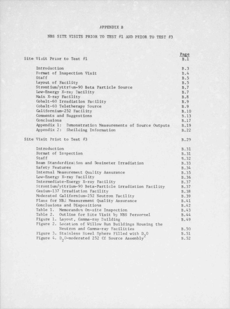
APPENDIX B
NBS SITE VISITS PRIOR TO TEST #1 AND PRIOR TO TEST #3
PageSite Visit Prior to Test #1 B.1
Introduction B.3Format of Inspection Visit B.4Staff B.5 |Iayout of Facility B.5 l
Strontium / yttrium-90 Beta Particle Source B.7 j
low-Energy X-ray Pacility B.7 |Main X-ray Facility B.8 |Cobalt-60 Irradiation Facility B.9 I
C balt-60 Teletherapy Source B.9oCalifornium-252 Facility B.10Comments and Suggestions 3.13Conclusions B.17Appendix 1: Demonstration Measurements of Source Outputs B.19Appendix 2: Sheilding Information B.22
Site Visit Priot to Test #3 B.29
Introduction B.31Format of Inspection B.31Staff B.32Beam Standardization and Dosimeter Irradiation B.33Safety Features B.34Internal Fkasurement Quality Assurance B.35Low-Energy X-ray Facility B.36Intermediate-Energy X-ray Facility
.B.37
Strontium / yttrium-90 Beta-Particle irradiation Facility B.37Cesium-137 Irradiation Facility B.38bbderated Californium-252 Neutron Facility B.39Plans for NB3 Measurement Quality Assurance B.41Conclusions and Dispositions B.42Table 1. Memorandum On-site Inspection B.43Table 2. Outline for Site Visit by NBS Persornel B.44Figure 1. Layout , Gamma-ray Building B.49Figure 2. Location of Willow Run Buildings Housing the
Neutron and Gamma-ray Facilities B.50,
i Figure 3. Stainless Steel Sphere Filled with D 0 B.512Figure 4. D 0-moderated 252 Cf Source Assenbly B.52
2
||
t
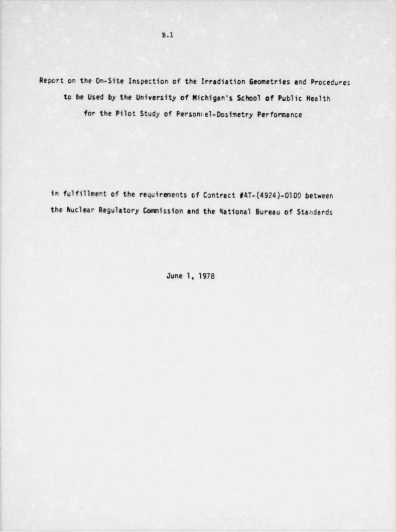
.- - _ _ _ _ _ _ _ _ _ _ _ .
B.1
Report on the On-Site Inspection of the Irradiation Geometries and Procedures
to be Used by the University of Michigan's School of Public Health
for the Pilot Study of Personr.el-Dosimetry Performance
in fulfillment of the requirements of Contract MT-(4924)-0100 between
the Nuclear Regulatory Commission and the National Bureau of Standards
; June 1, 1978
.
J
I
h
i
i
_ _ . _ _ _ _ _ _ _ - - - _ _ _ _-- .-- - .,
_ _ - _ _ _ _ _ _ _ _ _ _ _ _ _
B.2
Report on the On-Site Inspection of'the Irradiation Geometries and Procedures
to be Used by the University of Michigan's School of Public Health
for the Pilot Study of Personnel-Dosimetry Performance
( $~^4' ex-.
C. Eisenhauer, Radiation Theory T. Loftus, Radia /nDosimetry
(photons)
.
\ST $ 1W b y/Pruitt, Radiation Dosimetry V. Spiegel,ieutron Physics
(beta particles)
c, (.('
,,
''l , l,'. . t'.g z ~'
.
M. Ehrlich, Radiation Dosimetry
(Contract-Liaisen Officer)
h '7bDatei
_-_
- _ - _ - _ _ ..
B.3
Report on ths On-Site Inspection of the Irradiation Geometries and Procedures
to be Used by the Ur.iversity of Michigan's School of Public Health
for the Pilot Study of Personnel-Dosimetry Performance
1. Introduction
As specified in the Inter-Agency Agreement of June 30,1977 (contract number
0100) between the Nuclear Regulatory Commission (NRC) and the National Bureau of |
Standards (N35), NBS performed an on-site inspection of all irradiation facilities
involved, made actual observations of beam-calibration procedures, and examined
Iirradiation geometries and procedures, and plans for record keeping. The inspec-
tion was carried out on April 18 and 19,1978, i.e., about two weeks prior to the
start of the actual testing phase of the pilot study, and immediately preceding the
Open House on April 20 held by the University of Michigan's School of Public Health
(referred to ir. this document as the contractor) for the participants in the pilot
study. All N33 staff members remained at the University for the open house which was
attended by roughly thirty of the future participants in the pilot study. The
NBS project coordinator spent one more day (April 21) with the contractor for
some further in-depth discussions.<
In the following, a detailed account is given of the on-site inspection,
including the results of the critical study of the preparations made by the
contractor for the actual testing phase, and a list of the recommendations
by the NBS staff for alterations in layout or in the envisaged irradiation pro-
cedures and evaluations to be carried out during the active phase of the pilot
study.
1
.. - _
- ___ - _____ - _ _ _ _ _ _ _ _ _ _ _ _ _ _ _ _ _ _ _ _ _ _ ._
|'
B.42. Format of Inspection Visit
Each of the five members of the fib 5 visiting staff was involved in one or
more phases of the work covered by the ]nteragency Agreement. The five staff
cembers were:
C. Eisenhauer, Radiation Theory
V. Spiegel, Neutron Physics
T. Loftus, Dosimetry (photons)
J. Pruitt, Dosimetry (beta particles)
M. Ehrlich. Dosimetry (chairman, Work Group 15 Health
Physics Society Standards Committee, and contract-
liaisonofficer).During the first day and one-half of the visit, Professor P. Plato of the
University of Michigan School of Public Health and his associates gave a general
introductior, to the facilities, starting with a slide show and a discussion of genera
procedure to be followed throughout the pilot study, and ending with in-depth discus-
sions of source-calibration procedures and daily tasks connected with actual dosimetr,
irradiaticas, such as radiation protection for personnel and dosimeters, irradiation
geometry, quality control, and record-keeping. In the afternoon of the second day,
one of the hBS staff members (T. Loftus) maae demonstration measurements of the out-
put of the cobalt-60 irradiation facility (Room M6543 of Building SPH II) and the mair
x-ray facility Croom SB171 of Building SPH I), in the presence of Professor G. Hudson,
who is also on the str(f of the School of Public Health. The rest of the group 5 pent
afternoon discussi.ng with P. Plato the " Preliminary-Phase Report", submitted by the
contractor to the NRC on Narch 31, 1978.
2
__ . _ _ _ _ _ __ _ ____ _ _ _ _ _ _ _ _ _ _ _ _ _ _ _ _
B.5On the third day, the NBS team helped answ:r the numerous questions posed
by the future participants in the pilot stu:'y. One member of the NB5 team
(t!. Ehrlich) spent a fourth day with the contractor, mainly discussir.g tts means
for reconciling the 14B5 recommendations for further improvements in facility and
procedure with the desire of all parties involved to have the contractor. start the
irradiation phase of the pilot study on the specified date of May 1.
3. General Observations
3.1 Staff
The University staf f involved in the pilot study consists of three persons:
P. Plato, a member of the University of Michigan's School of Public health for many
years, G. Hudson, who joined the staff in the Fall of 1977, and S. Peavey, technical
assistant, who was hired in early April,1978, but who has been associated for some
time with the University, both as a student and as a technical assistant in another
departrent. Furthernore, tie Radiation Policy Committee of the University has assigned
Mr. Richard hevil, a health physicist, to assist with various radiation-protection
aspects, particularly around the neutron source. The NBS team was impressed by the
time and effort expended by the staff of the contractor in the preparation for the
pilot study; the attention to detail in a field somewhat remote from their previous
experience; the orderly manner of preparing for the handling of the flow of large
numbers of dosimeters and maintaining records for receiving, irradiation, and shipping
the dosimeters; and their cheerful acceptance of criticism by the NBS personnel and
willingness to make the recommended improvements.
3.2 Layout of Facility
Three of the six sources to be used in the personnel-dosimeter irradia-
tion program, as well as the dosimeter receiving and storage room, are housed on
the sixth floor of Building SPH II of the School of Public Health, with a storage
3
__ - __ _ _._. . . _ _ _
___ - _ _ _ - _ _ _ _ - _ _ _ _ - - - - . _ - - -
B.6
room about 25 meters from the only penetrating source (cobalt-60 irradiator)
en this floor, and the closest irradiation room (housing the General Electric
x-ray diffraction unit) being about 17 meters away. The other (main) x-ray
machine (General Electric Maxitron) is housed in the sub-basement of the
adjacent Building SPH I (in room 5B171), whila the cobalt-60 teletherapy unit to
be used for larger cobalt-f,0 gar:na-ray exposures is located in the University
Hospital, sone two blocks from Buildings SPH I and SPH II. The storage shed
housing the c:lifornium-252 source is located at the now-closed Willow Run Air
Force base, parts of which have been purchased by the University.
1
4
_ _ _ _ _ - - - - - - ----
-_
$
B.7,
4. Inspe: tion of Individual Irradiation Facilities
In this section, observations are made on each individual-irradiation
|facility inspected. Comments, suggestions, and recommendations pertaining to
| general procedure are included in section 5.
4.1 Strontium-90/ Yttrium-90 Beta Particle Source;
This source is located in room M6333. It was calibrated at NBS. An,
independent measurement 'of the source by the contractor agreed to within a
fraction of one percent with the NBS calibration. In the contractor's setup,
the source holder and phentom are rigidly connected in such a way that there is,
; little chance of variation in the r,ource-to-phantom distance, even over prolonged:
i periods of time. The source itself is mounted in its box in a manner that makes
! changes in source orientation very improbable. Nevertheless, inasmuch as the source
: disk is free to rotate somewhat on a hinge in the handle, J. Pruitt suggested thati
the disk be restrained, perhaps by means of a small wedge. The digital timer to be.i
! used with this source was found to be defective and it was recommended that it be
repaired or replaced. Measurements at NBS by J. Pruitt under slightly different
I conditions indicated that the contribution from scatter of the contractor's shutter
: channel was negitgible. This fact also is borne out by the agreement between the,
results of the contractor's absorbed-dose measurements in the presence of the shutter;
channel and of the NBS absorbed-dose measurements in its absence.;
; 4.2 Low-energy 2-ray Facility
This facility, which is located in room M6150, consists of a General
Electric x-ray diffraction unit which had been previously used for radiobiological
| work. Its high voltage has not been checked recently. However, since the contractor
was able to reproduce the NBS L-G. technique's first HVL and homogeneity coefficient1
| to within 5 percent, performance of the unit is considered adequate, provided more;
i
||'
5
_ _ ___ - . . . -_ __ _
_ _ _ _ _ _ _ _ _ _ _ _ _ _ _ _ - _ _ _ _ _ _ _ _ _ _ _ _ _ _ _ _ _ _ _ _ - . __
B.8
positive means for automatic timing be furnished and improvements be made in the beet-
conitoring chatter. (T. Loftus suggested that the aluminized Mylar window be tightent
and that the flylar; might be replaced by thin alu:tinum, since the aluminized Mylar istr.usp rer.t to
somewnat eiectrostatic effects.) It was further suggested that the unused half ofg
the lead-lined box now in room M6150 be used as part of a dosimeter-storage box in
the control room of the main x-ray facility.
4.3 Main X-Ray Facility
This facility, which is located in room SB171 (sub-basement), consists
of a General Electric Maxitron 300 resonance transformer x-ray unit. It is not
a constant-potential unit, its voltage and current frequency presumably being 1200
cycles per second. It is equipped with a stationary-enode x-ray tube, whose filament
is heated by the current from the secondary coil of the resonance transformer.
General Electric recently adjusted the current-voltage overload circuit of the unit,
but did not measure the actual high voltages generated by the (completely sealed)
transformer. The output of this unit evidently is smaller by more than an order cfx-ray
magnitude than that of the constant-potentia 1 tube used by NBS.3The beam filters available to the contractor for obtaining the spectra
corresponding to the desired NBS techniques were found in part te be of unknown
crigin. Also, their number proved ins.3fficient for making filter packages for each
of the NBS techniques desired, end there was not enough filter material available
for obtaining two half-value layers in aluminum. It was recommended that the
contractor purchase a new set of filters and then repeat all calibration procedures,
employing the improved vibrating-reed current-measuring setup discussed in Section 5.
For a description of the demonstration-calibration procedure, sr.e Appendix 1 to
this document.
l
6
_
_ - . . - - - _
B.9
4.4 Cctalt-60 Irradiation Facility
This facility, located in room H6543, is a Sheppard Model 28 beam-type
irradiator, in which the source fs locked in the "off" (closed) position in a centi _,
cylinder inside the protective housing. A source-raising mechanism enables the
operator to lift the source for an automatically timed period to ihe irradiation
position. In this position, the collimator permits a radiation beam to exit into a
. 30-degree solid angle. In the contractor's setup, the exiting beam is directed toward,
i
the exterior wall of the sixth-floor room, striking mostly windows. C. Eisenhauer
computed the back-scatter from the window wall to be less than 0.1 percent. The
contractor supported the irradiator on concrete blocks laid on the floor of the ro';m
and suspended the plumb lines for locating the phantom from the false ceiling of the
room. Because of the possibility of shifts both in source and phantom-plumb-line
positions. T. Loftus recommended that the distance from the source to the phantom be
established by means of a bar, cut to proper length, whose sourca end is shaped to,
>
fit convenier.tly around the source housing. The demonstration measurement performedI
: on this source by T. Loftus is included in Appendix 1..
4.5 Cobalt-60 Teletherapy Source
This source, a Theratron-80 teletherapy facility of the Atomic Energy
of Canada, Ltd., is located in the basement of the University Hospital. Since it
is in use for eight hours at least five days a week, irradiations will have to be
carried out at night and on weekends. The room arrangement (size, radiation
protection) is adequate for dosimeter irradiation with a horizontal beam in the4
direction chosen by the contractor. C. Eisenhauer computed that the background due
I
1
; 7
.
. , _ . _ . ,. 7 - - - - - - - - - v -- ----
-___- _ _ _ - _ _ _ _ _ _ _ _
B.10
to photons scattered from the wall struck by thE beam to be less than 0.1 percent,
assuming that a distance between the detector and the wall greater than 150 cm
is maintained, and that the collimation produces a 36 cm x 36 cm beam spot on the wall.
4.6 Ca11fornium-252 Facility
This facility occupies Building 2209 of the University of Michigan's
Willow Run Laboratories. The building consists of one room, about 7.5 m x 33m
in grocnd area and 6 m high, containing a smaller (3.5 m x 3-1/2m) enclosure,
which is to be used as a control room. The control room has a telephone, on the
University exchange. Building 2209 was chosen in favor of a smaller room on the
University's main campus upon the advice of C. Eisenhauer who carried out computations
of the contribution of neutron scattering to the irradiation levels at the contemplated
phantom locations for both rooms.
While the facility is not completely finished, mainly because the
contractor still lacks the license to operate the source, the preparations for
this entirely new facility are quite thorough. Source-container installation
and source-raisira mechanism are adequate. All required structures maintain the
necessary open, scatter-free geometry. The following recommendations are made
in connection with source operation:
(a) Inasmuch as the design of the wand which screws onto the
californium-252 source has been changed from that used at NBS, the reproducibility
of source positioning will have to be shown to be adequate for the required level
of irradiation accuracy at the two contemplated irradiation distances.
(b) In the unlikely event that the source should fall off the support
wand, it probably would fall back into the shipping cask through the guide tubes.
8
_____ _ ________ -
i
B.11
However, it is recommended that a skirt be taped to the bottom of the shipping
j cask so that the source cannot be lost under the shipping cask if it falls into
the open pit containing the cask.
(c) It is recomended that en 8-foot source-handling device and a
portable survey meter be stored in the control room. An emergency procedure
should be posted in the control room, requiring the operator to notify Health
Physics and remain in the shielded area, in the event that the irradiation
facility monitor indicates that the source is not in the storage cask at the
cnd of an irradiation, or in the event of monitor failure.1
(d) A scaffold platform with wheels should be provided for use by
the operetor during positioning of the dosimeters on the phantom.
! (e) It is recommended that a telescope be available with a power!
, sufficient for visual observation of the source while it is in the irradiation!i position.
J (f) It is recommended that a concrete-block shielding wall be installed
around the control room, and a shielded area for dosimeter storage, also built,
of concrete, be provided in the control room for storage of one-day's supply of
| dosimeters to be irradiated. Shielding data for three different types of concrete
are provided for this purpose in Appendix 2. It is expected that the contractor
will cooperate with the Radiation Policy Committee of the University through
Richard Nevil in the design of these shields, as well as in the design of the
external barrier which this Committee requires to be erected around the entire
building.!
Furthermore, the following observations and recommendations are made
rcgarding dosimeter irradiation and dose-equivalent index computation:
I
_ . -.
-- _ _ _ _ - _ - _ _ _ - _ _ _ _ _ _ ___
B.12
(a) Simultaneous use of two phantom:,, one on each side of the source,
is permissible. C. Eisenhauer's computations indicated that the cross-talk con-i
tribution to the dose equivalent for a dosimeter placed 1 m on one side of the
s:urce due to a phantom at 50 cm from the source on the opposite side, is about
1 percent. Cross talk for the reverse situation (i.e., detector at 50 cm and
scattering phantom at 1 m) turned out to be less by an order of magnitude.
(b) For dosimeters at a 1-m distance from the source, C. Eisenhauer
computed that the scatter contribution to fluence is about 9 percent and to dose
equivalent about 6 percent. For the same position, he computed that the scattered
neutrons would cause an albedo-neutron dosimeter to read high by about 17 percent,
while, at a distance of 50 cm, it would read high only by about 4 percent. Therciore,
it is re:ommended that (1) the dose-equivalent index computed for a particular
dosimeter at a 1-m distance be increased by 6 percent; and (2) albedo-neutron dosimeter
be irradiated at a distance not larger than 50 cm.
(c) There is general agreement among users of californium-252 fission-
neutron sources that the ratio of gamma-to-neutron-emission rates is constant
with time daring the first several years after source separation. (See,e.g.,
page 26. ICRU Report 26, quoting C. N. Wright of the Savannah River Laboratory.'s
Furthermore, the number quoted for the gamma-ray exposure rate may be assumed
to be about 100 R/h at 5-cm distance rather than the roughly 300 R/h given in Table III
of the 1977 Grundi et al. paper in Nuclear Technology. For reporting irradiations'
in category VIII, it is recommended that the value for the gamma-raf exposure rate
for the contractor's californium source be increased by 1.9 mR/ min at 1 m in order
to account for the gamma-ray background.
10
,
B.13
5. Commerts, Suggestions, and Recomnendations Pertaining to General Procedure
5.1 Radiation-Protection Considerations
While most of the sources employed will not pose a hazard to the staff
or cause unwanted irradiation of the dosimeters, NBS made certain recommendations,
both regardir.g protection of personnel and protection of dosimeters from inadvertent
exposure. Those specific to a given source are treated in the discussion of that
source in Section 4. The general recommendations are:
(a ) . Have working radiation survey meters remaining at the control of
cach radiation source.
(b). Survey the control rooms and other rooms adjacent to the roc =s
housing the more penetrating radiation sources while the sources are in use.
Take steps to reduce radiation levels, where necessary.
(c ) . Refrain from taking supplies of dosimeters into the irradiation
rooms, except when they are to be positioned for irradiation. Have storage
boxes with prote:tive lining (lead against photons, concrete against neutrons)
for the day's supply of dosimeters in the control rooms or in other rooms adjacent
to those housing the more penetrating of the radiation sources.
5.2 Point of Radiation Measurement
Inasmuch as a rather wide variety of dosimeters of different shapes
and dimensions (different thicknesses) will have to be irradiated "on-phantom",.
I
11
..
_- _ - _ _ _ _ _ - _ _ _ _ _ _ _ _ _ _ _ _ _ _ _ _ _ _ _
B.14
hB5 recommends that all radiation measurements be carried out in the plane of the
phanton surface facing the source (with the phantom removed), and that the participant;
be informed of this procedure. Participants who prefer to calibrate in a different
plane will be able to adjust their calibration data on the basis of the contractor's
irradiation distances, which in some instances the participants will have to
infer. For positioning a dosimeter on the phantom, a styrofoam wedge will
be fastened to its back on the opposite end of the clothes clip, to maintain the
dosimeter's front surface parallel to that of the phantom. The rationale behind this
procedure is that the air space thus created between the dosimeter and the
phantom roughly will approximate the space between the dosimeter and the human
body when the dosimeter is clipped to the coat lapel of the wearer.
5.3 Computation of Dose-Equivalent Index from X-Ray Exposure
It is recommended that the contractor compute the conversion factor for
each x-ray technique employed by weighting the factors given in Table 2 of ANSI N-716,
Proposed Standard Criteria For Testing Personnel-Dosimetry Performance (to be published
as ANSI N-13.ll), by the approximate exposure spectrum corresponding to this technique.
For the tine being, the use of spectra obtained by Kramers-type calculations will be
considered adequate. Eventually, NBS will provide the contractor with measured spectra
for each of the techniques employed.
5.4 Reproducibility of Phantom Position
In order to provide a positive check on phantom location and to insure
reproducibility in its positioning in relation to the source after it has
been moved for calibration checks, it is recommended that the make-shift plumb
bobs now in use be replaced and that, at the cobalt-60 irradiator, a rigid bar be
used in addition (See section 4.4).
12
_________ __ _____ ._
_
J B.15
5.5 Check of Actual " Source-Open" Times and of Timer Functioning
It is recomended that, on all sources for which calibrations are
performed, these calibrations be carried out both independent of source-shutter.
(cr ' source-raising-and-lowering) functions, i.e., in a steady-state determination
of the ionization current, and dependent on these functions over the range of j
rcalistic dosimeter-irradiation times. Also, timer redundancy should be provided
in order to check on timer accuracy.;
S.6 " Cross Talk" Between Dosimeters and Unifonnity of Irradiation Over
Dosimeter Area.
It is recommended that the influence of scatter from any one dosimeter
j to its neighbors (" cross talk") be checked for representative dosimeters and for;
i all sources. It is further recomended that the irradiation geometries be chosen:
in such a way that the variations of primary irradiation-rate parameters (exposure,i
!
absorbed dose, fluence) vary by less than 2 percent with radial positioning of the,
dosimeters. This will eliminate the 50-cm distance proposed for use with the General
Elcctric Maxitron x-ray source, and will decrease the useful portion of the strontium-90
b:am at a 35-cm distance to a central area of not much more than 6 cm in diameter.
Inasmuch as cross talk probably will not be observable for strontium-90 beta irradiation'4
Gwen with dosimeters in contact with each-other, the number of dosimeters that can be.
;
irradiated simultaneously with strontium-90 beta particles will depend on the size of,
the particular dosimeters,i
! 5.7 Detennination of Rates at the Dosimeter Positions
It is recommended that, for all photon sources, the exposure rates be,
!j datennined repeatedly at the point of the phantom surface corresponding to the
cidpoints of the dosimeters. Only if the spread in the average rates for all,
|
:
13.
_ ___ _. . . . - . _
._.
_-
- _ _ _ _ _
B.16
six dosimeter-center points at the phantom surface is no larger than the
fluctuations in individual readings at any one point should the exposure
time. be computed fram a mean rate for all six dosimeter positions.
5.8 Contribution of Room Scatter to Dosimeter Irradiations
Since it was felt that the room scatter measurements made by the
contractor overestimated the scatter contribution to the exposure from the
cobalt-60 gama ray sources, scatter contributions were computed both for
the cobalt-60 gamma irradiator and the teletherapy unit. They actually
turned out to be much smaller. (See sections 4.4 and 4.3.) However, the
contribution of room scatter to the californium-252 irradiations in the
Willow Run warehouse was computed to be significant. (See section 4.6.)
5.9 Location of Current (or Voltage) Measuring Equipment and Mode of
Measurement
It was recomended that the measuring equipment (Cary Vibrating-Reed
Electrometer and accessories) be moved from the photon-irradiation, rooms where
it could be subjected to scattered radiation from room structures, causing
extra-cameral ionization, to the shielded control areas; and that the present
s.ignal cable and connectors be replaced by a lo.ng low-noise cable with a specia1.
ispring-loaded connector that screws inte the preamplifier head of the electro-
meter. It was pointed out furthermore that by introducing a potentiometer into
the feed-back ' circuit, ionization current (via a calibrated high-ohm resistor)
or charge (via a calibrated capacitor) can be determined by means of a potentio-
meter using a null method,which gives results that are independent of electrometer~
characteristics such as gain or linearity. The advantage of method redundancy
was stressed.
14
_
- .. .
B.17
3J
5.10 Use of Secondary Ion Chambers
It is customary to refer calibration factors of Victoreen R-meters,
to 760 mm Hg and 22'C. The instrument is calibrated at mid scale and cara
shsuld be exercised not to depend on readings at small fractions of full scale.
The buildup cap provided with the 100-cm3 Shonka-type chamber should.
j be used only for cobalt-60 ganna irradiations.. For photon energies below about
50 kev the response per unit exposure varies strongly with photon energy.4
ThGrefore, it would be inappropriate to use this chamber at these photon energies,3
| unless the spectrum of the radiation employed matches closely the spectrum for
which the chamber was calibrated..
;
: 6. Cone.lusions)
| On the basis of the findings dircussed in this report, the NBS team submitted,
'
a letter to Mr. Robert Alexander of the NRC Office of Standards Development, ir1
which qualified approval was given for the contractor to start dosimeter irradiations
en four of the six scurces to be used in the pilot study. Following is a copy ofthe pertinent passages from this letter:1
.j Except for a need for (1) improving the arrangements for providing!
reproducibility of the location of the phantom (improved plumb lines, meter4
; bar at the cobalt-60 irradiator); (2) surveying the exposure rate in the rooms4
j adjacent to the irradiation rooms; (3) replacing or repairing the digital
timer of the beta-frradiator; and (4) providing e lead-lined. temporary;
i
storage box for personnel dosimeters in the room adjacent to room M 6543'
which houses the cobalt-60 irradiator, the following setups are ready for
| dosimeter irradiations to start on the basis of presently available beam:
| calibrations:,
154
__--- __ - . _ __.- . . - - -- . --- - _ . . - .. , _ -
-- - - - _ - ___ - _ _ - _ _ _ _ - _ _ _ _ _ _ _ _ _ _ _ _ _ _ _ _ _
B.18
(a) Room M 6333 (strontium-90/ yttrium-90 source)
(b) Room M 6150 (x-ray diffraction unit)
(c) Room M 6543 (cobalt-60 irradiator)
(d) Therapy Department, University of Michigan Hospital (cobalt-60
teletherapy unit).
It should be understood, however, that the final values for the shallow and/or
deep dose-equivalent indices associated with these irradiations will be com-
puted only after (1) the procedures connected with the determination of the
exposure rate at the front surfaces of the phantom will have been repeated
for the setups (b), (c), and (d) with the improved current-measuring system
suggested by NBS; and (2) a weighted average conversion factor from exposure
to dose-equivalent index will have been computed for the irradiation
spectrum employed in room M 6150,
It is espected that, as soon as the new filters are available which are
to be used at the General-Electric Maxitron x-ray source, and as soon as all
photon-measurement procedures are completed, T. Loftus will make a second
inspection trip to the contractor, prior to the final approval of all photon-
exposure rates obtained by the contractor and prior to the start of dosimeter
irradiations with the General-Electric Haxitron x-ray source. It is hoped that
telephone discussions will suffice for NBS to monitor the progress on the
Willow Run neutron facility without the need for a further inspection trip prior
to the start of dosimeter irradiations on this source.
16
- - - - ____ _ _ _ __ _ _ _ _ _ _ _ _ _ _ _ _ _ _ _ _ _ _ _
B.19
Appendix 1
Demonstration Measurements of Source Cutputs
by
T. P. Loftus
(a) Cobalt-60 Irradiator
i Check measurements on the output of this source verify with reasonable
accuracy the calibration data of the contractor. Measurements were carried out
with a Cary Model 31 vibrating-reed electrometer in the " integrate mode," using
a capacitor which was supplied by NBS.
The time required to increase the feed-back potential on the electrometer
system from some initial value to a final value was determined using a Hewlett-
Packard 55 calculator-timer. These data, together with a knowledge of the capacitance
the system, and the cavity ionization chamber's calibration factor, were used to
compute the exposure rate at the position of the chamber. The same technique
was used, but with a Data Precision digital voltmeter, to measure the potentials
in place of the electrometer's voltmeter. It appears that there is a statis-
tically significant difference of the order of one percent between the two sets
of measurements.
The ionization measurements were carried out independent of the shutter
cperation. To check the effect of source movement on timing of exposures, the
sturce was raised and lowered several times, with the tirner which is activated
when the source is in the irradiation position used to record the total " source-t
cpen" time. The irradiation tirie, computed from the steady-state ionization current
determined in the earlier measurements and the total charge accumulated during the
several irradiations, agreed closely with the time shown on the " source-open" timer.
17
_ _ _ _ _ _ _ .
7- - - - _ - - - - - - _ _
B.20
For all these measurements the measuring equipment was positioned such that
it could be sutjected to scattered radiation from the beam, walls and windows.
This is not good practice since measurements may be affected by extra-cameral
ionization. It was suggested that the equipment be moved to the laboratory area
in back of the source. It was also noted that the cable connecting the cavity
chamber to the electrometer was not of the low-noise type and that several connectors
were required to connect the feedback capacitor to the electrometer input. To
alleviate these difficulties a long low-noise cable with a special spring-loaded
connector. which screws into the preamplifier head of the vibrating-reed electrometer,
has been provided by NBS.
The contractor reported good agreement between ionization-current measurements
with the NBS-supplied capacitor as the feedback element and the currents measured
using an NES celibrated "hi-megohr?' resistor as the feedback element. It was pointed
out that another measurement method exists which does not rely on the characteristics
(such as gain, linearity) of the electrometer, which is a mt:thod in which the
electrometer is used only to detect a null. This is accomplished by introducing
a potentiometer into the feedback circuit with polarity such that the ionization
current is nulled. The method can be used for " integrate" (charge) as well as
rate (current) measurements. It was emphasized that all these methods should give
consistent exposure data and redundancy should be used to check calibrations of
the sources.)
(b) Main X-Ray facility
The equipment used for measurements with the cobalt-60 irradiator was moved j
down to the General Electric Maxitron x-ray facility. Because of the short cables
it was necessary to position the equipment in the irradiation room and read the
18 |
_ - _ - _ _ _ ___
. - - _ .
B.21
teters through the lead-glass window. The new, long, low-noise cable and
connector will allow the equipment to be moved into the ante-room with the cable
led through a lead-covered opening in the wall. The principles of ionization -
current measurements discussed in the section on the cobalt-60 irradiator pertainhere also. -
Heasurements were carried out with the machine set for meter reac'ings of
100 kV and 5 mA. The cavity chamber was positioned at 1 m from the tu)e target.
Comparison with expected output based on constant-potential data from an NBS .
machine with the same filtration showed that the Maxitron output was about an
crder of magnitude lower. With reference to the manual for the machine it was
found that it is of the resonant transformer type and although it may be considered
to be at constant potential it is only at the set potential a fraction of thetime.
Absorption data in aluminum were recorded and the HVL was found to be close
to the NSS value for this technique but the ratio of the first to the second HVL
(the homogeneity coefficient) did not agree with the NBS value. These measurements
should not be considered definitive however since the filter material was not
adequately identified or measured for thickness. These measurements should be
carried out under better circumstances with the measurement equipment out of the
irradiation room.
Since the General Electric Maxitron x-ray unit has a 3.75 mm Be window the
contractor has added 1.5 mm Al to the filter combinations published for the NBS
techniques. This adds slightly more filtration to the beam than is necessary,
however the effect on the spectrum would be negligible. The effects of x-ray
tube potential and current surges can be checked using the principles outlined
in (a), i.e., the output is measured for a steady-state condition and the
13tal exposure resulting from several on-off exposures compared with the exposure
cxpected from the steady-state data. --
19
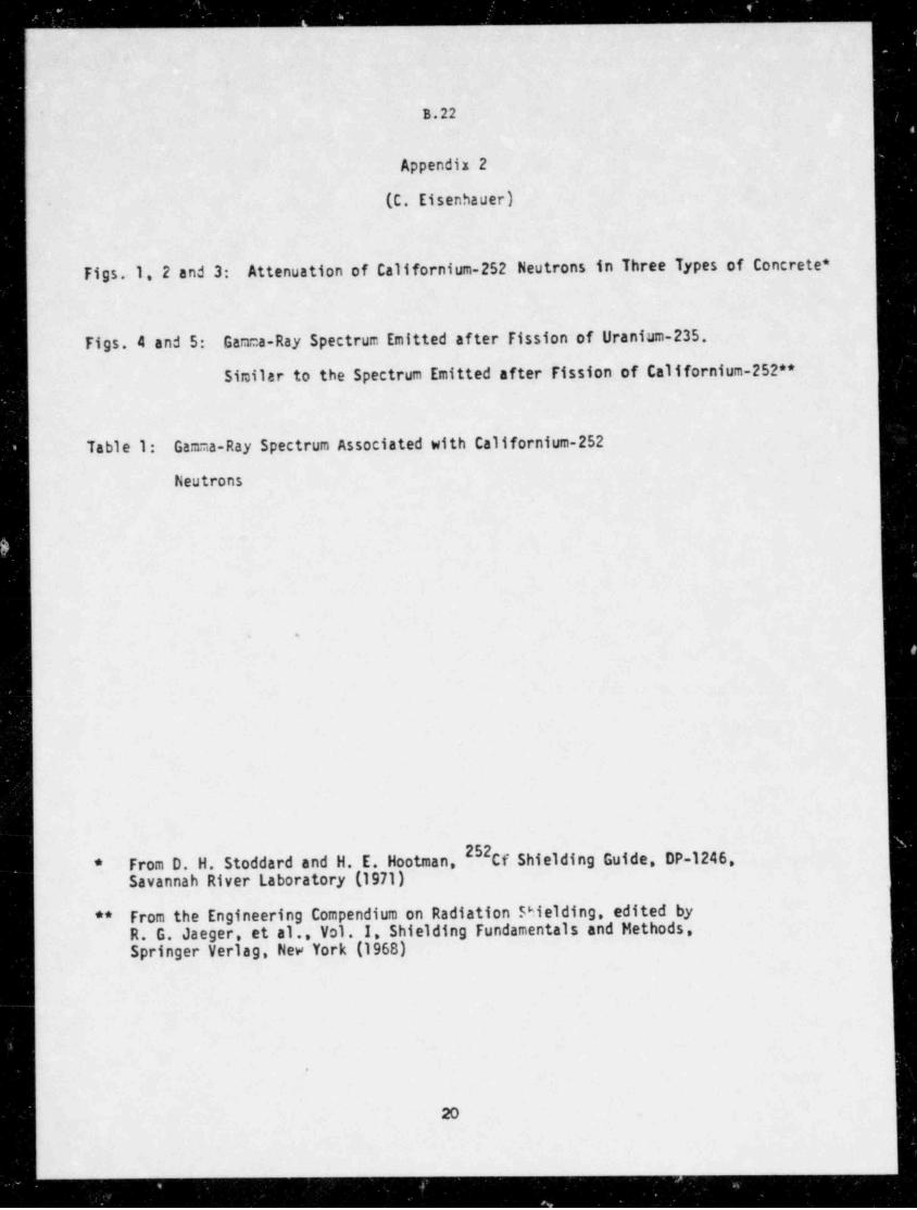
s ______
B.22
Appendix 2
(C. Eisenhauer)
Figs. 1, 2 and 3: Attenuation of Californium-252 Neutrons in Three Types of Concrete *
Figs. 4 and 5: Gamma-Ray Spectrum Emitted after Fission of Uranium-235
Similar to the Spectrum Emitted after Fission of Californium-252**
Table 1: Gamma-Ray Spectrum Associated with Californium-252
Neutrons
.
52From D. H. Stoddard and H. E. Hootman, Cf Shielding Guide DP-1246,*
Savannah River Laboratory (1971)
From the Engineering Compendium on Radiation Shielding, edited by**
R. G. Jaeger, et al., Vol. I, Shielding Fundamentals and Methods,Springer Verlag, New York (1968)
.
20
- . .
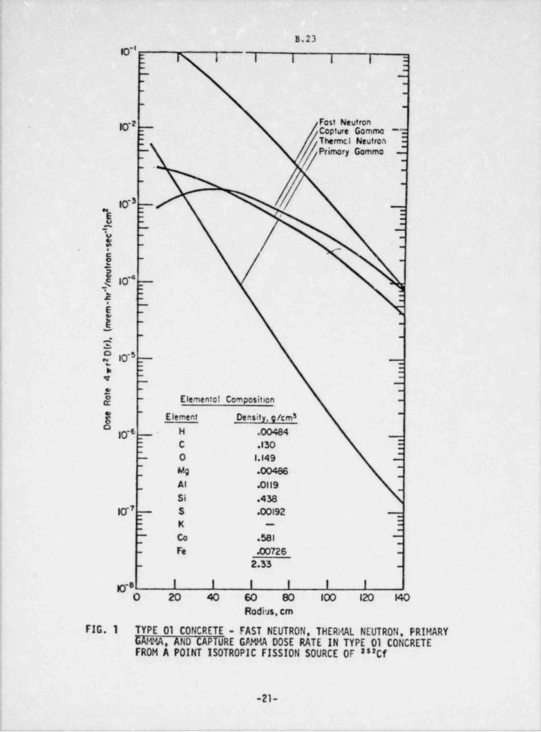
B.23,
g-ii I I I I | :.
;-
--
--
j --
i --
2 Fast Neutron'
U F Copture Gommo - =*
j - Thermcl Neutron :,
/ rimary GommaP-
4 -
; : -
1 -
i --
10-3 --~
E1 e = .
; u -
_-, :- -
i 3-
-
:.. r -
-
!, 8 --
2
#10
--
2 : :i
| 5 - '
_
i, _E .-
-
--,
I E10~5 ---;
! I : :_
e --
,
; . --
] j - Elementot Composition -.
' ~
Element Density, g/cm3{ ~
) 10-8 -. H .00484
_
! : C .130 :~ ~
i- O l.14 9 -
,
j [ Mg .00486 [j
_Al .0119
_
5 Si .438i 7j E -. S .00192
_
j } K E-
i. Co .581 ' --
- -
j Fe .00726- -
] - 2.33 -
1 -
go I I I I I I'
O 20 40 60 80 10 0 12 0 14 0
; RadiJs,em.
i FIG. 1 TYPE 01 CONCRETE - FAST NEUTRON, THERI%L NEUTRON, PRIMARYI GAlt% AND CAPTURE GAM % DOSE RATE IN TYPE 01 CONCRETE
FROM A POINT ISOTROPIC FISSION SOURCE OF as:Cf;
! .
i
! -21-t
i;
- _ -. -. . - - - - -- _
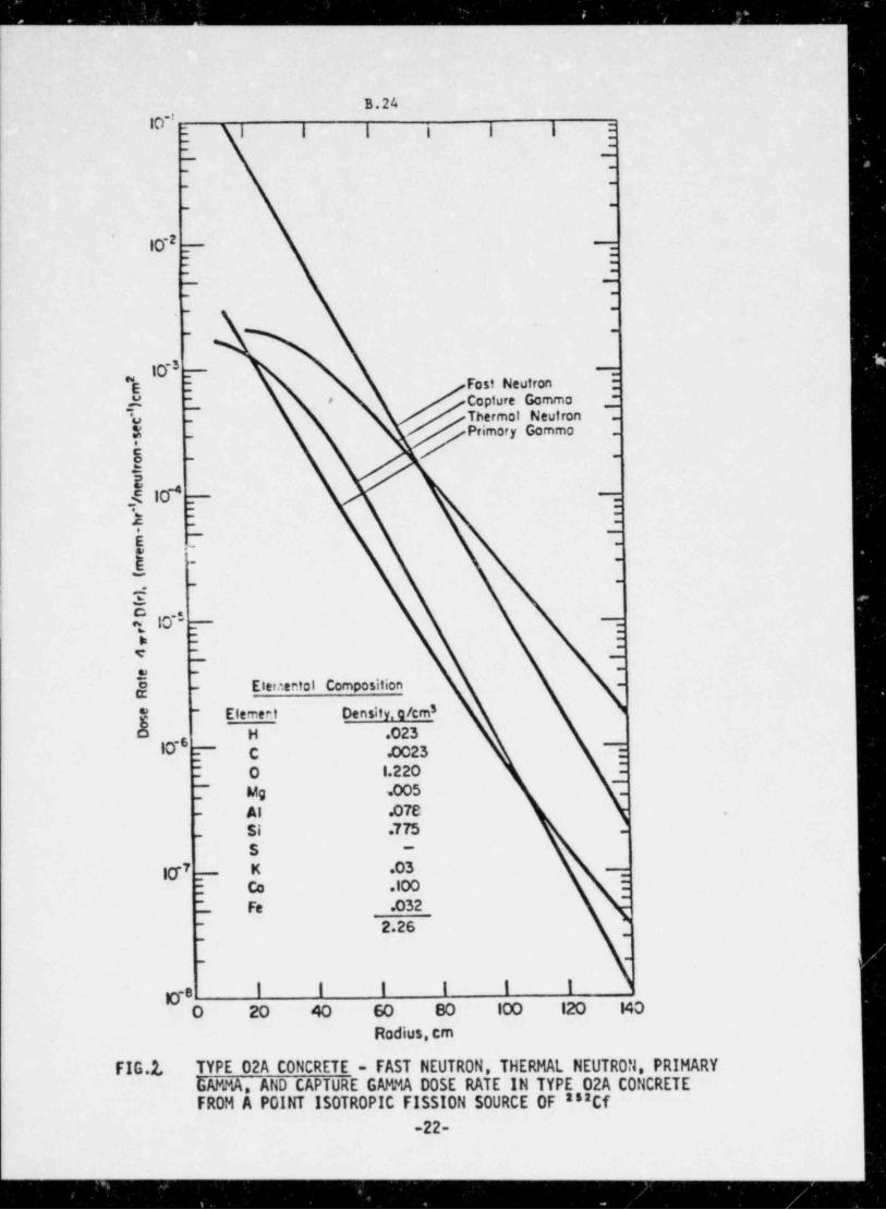
.. _ _ _ _ _ _ _ _ _ _ _ ____ _ ______ - ______ _ _ _ _ _ _ _ _ _ _ _ _ _ _ - __ _ _ _ _ _ _ _ _ _ _ . _ _ _ _ _
B.24O'' ;
I I I i i i :
: :_
-
--
--
--
10-2 __-
: :-,.
_
.-
,_ -
- -
10-3 --
"E- Fast Neutron -
Copture Gommo -E - *~
'o T Thermo! Neutrony - / jPrimary Gammo8 - / -
E< i&* _ -
-
: :-s - -
E 7 Iw rg - -
_
,-
-
sO 10-5 _ -
1 : :
v --
- -
., --
j - Eternental Composition -
3Elemert Density. c/cm* -
b H .02310-5
: C .0023 :
O l.220 :-
T Mg .005 -
Al .078 .-
Si .7M --
S -
30-7 K .03 _,
- Co .100~
-
Fe .032-
~ 2.26-
-
- -
g-e 1 I I I I I
O 20 40 60 80 10 0 12 0 14 0
Radius, em
FIG.1 TYPE 02A CONCRETE - FAST NEUTRON, THERMAL NEUTRON, PRIMARYGAMMA, AND CAPTURE GAMMA DOSE RATE IN TYPE 02A CONCRETE
858CfFROM A POINT ISOTROPIC FISSION SOURCE OF
-22-
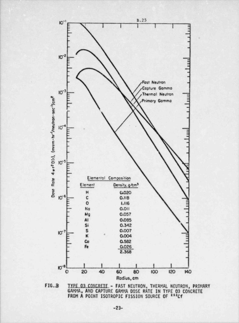
_ _ _ _ _ _ _ _ .
B.25g.:4 : I I I I I :'
-
.-
-. ,
- .,
; - -i
10-2 _
::-
I ~
-
- .
- -
! - - Fast Neutron -!
; Copture Gommo
] 10-3 - Thermot Neutron ::_.
,, _
! $ ! f rimary Gamma _"P_
1 -r - -
~ ~
! g - -
: A
| f 10-* _ .*
_
: : : ,
1 2 - -
i! E - -
~) E
- .
, - - _
I 4E 1041 3
-
~ ~
i -
- Elemental Composition{ 3 ,
| $_
Element Density,ghm3,
| fs H 0.020j g
_ C O. IIB; ; O l.11 6 :
l L No 0 . 0 11 2~
j_
Mg 0.057| Al O.085
~
| Si O.342| g7 S 0.007
,* -
j : K O.004;
_ cc O.582 _-j Fe 0.026- -
2.368- -
: - -
.
! ga I i I I I i! O 20 40 60 80 10 0 12 0 14 0,
! Radius, em-
4 FIG.3 TYPE 03 CONCRETE - FAST NEUTRON, THERMAL NEUTRON, PRIMARY! GAMMA, AND CAPTURE GAMMA DOSE RATE IN TYPE 03 CONCRETE
i FROM A POINT ISOTROPIC FISSION SOURCE OF as:Cfi
-23-i
i _ . _ _ - .- _- - -_- _ _ - . . . . . . . _ - - . _ _
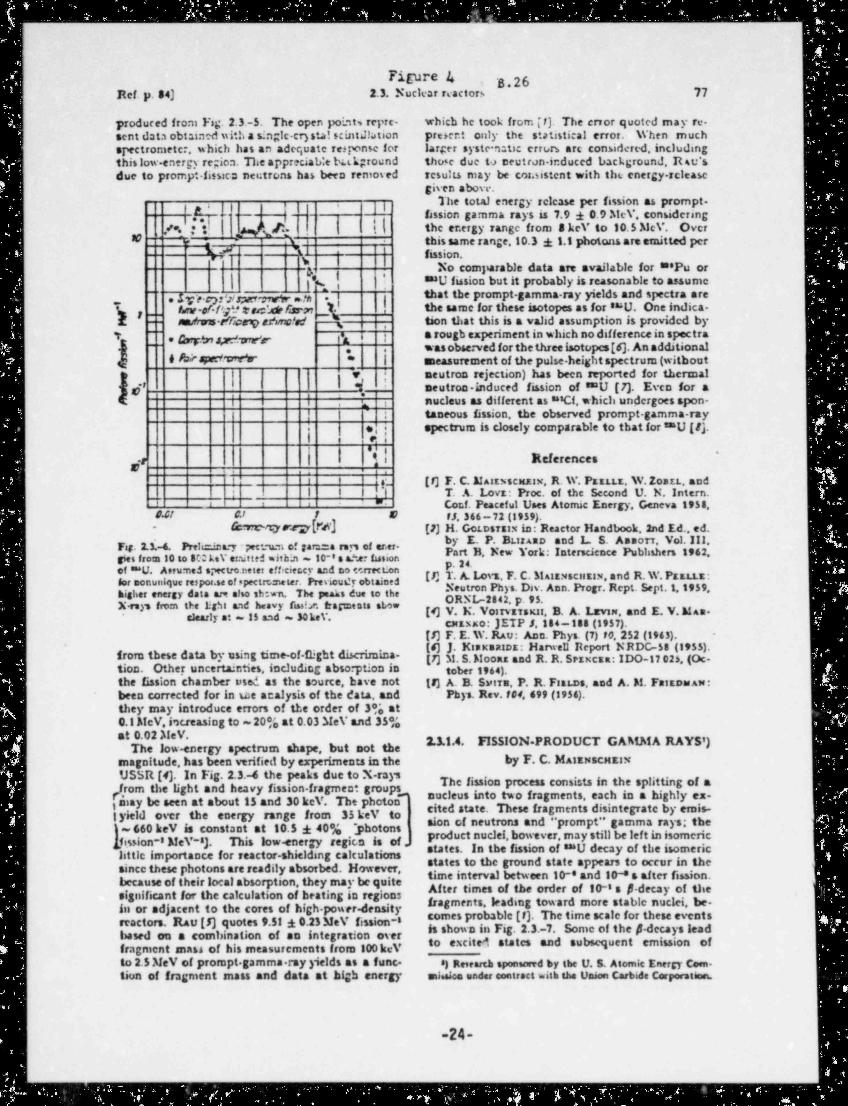
Figure 4 B.26i
Ref. p. 34) 2.3. Nuc1 car reactors 77
produced from Fig. 2.3.-5. The open point, repre- which he took from [f). The ervor quoted may re.sent data obtained with a singic-cry stal scint& tion preser:t only the statistical error. When muchspectrometer, which has an adequate response for larger systemtic errt,rs arc considered, includingthis low-energy region. The appreciab:e bakground those due t> meutron-induced background, Rsu'sdue to prompt.fissien net:trons has been remosed results may be cosaistent with the energy-rclease
given above.The total energy release per fission as prompt.jg, ,
-- .k.-- - ' - -
|
.
,
fassion gamma rays is 7.9 i 0.9 MeV, considering,| the energy range from a kev to 10.5 McV. OverI g (#.'8 -"/*. ; t
-
ti this same range,10.3 i 1.1 photons are emitted pert
- --
Q j fission.No comparable data are available for ***Pu or
| f.%.!'
I "U fission but it probably is reasonable to assume"'
. Mr.epwr,:ver enrtrwini| |that the prompt-gamma-ray yields and spectra are
.
_ f,w-of /'f@> t ad. Mas mJ. the same for these isotopes as for suU. One indica-b ,
f, _- m/rwas r e9 eAnc!ad --A tion that this is a valid assumption is provided by,
; a rough experiment in which no dif ference in spectra-
, g g.,,y,,. ., ,
was obse:ved for the three isotopes [6). An additional-
. .
I&W,*, * | measurement of the pulse-height spectrum (witbout
| |v, ; neutron rejection) has been reported for thermal
d' i' neutron. induced fission of 8"U [7). Even for a
I nucleus as different as #'Cf which undergoes spon-s ,
| t taneous fission, the observed prompt-gamma-raya e, j spectrum is closely comparable to that for 8=U [t].t.
, c.. .,
gr | 1 7i References'
t i t r_ [7] F. C. Martwsexzaw, R. W. Pzatts. W. Zostt, andi I ,1 T. A. Lovz: Proc. of the Second U. N. Intern.,1_,
' ' " ' - Cor.f. Peaceful Uses Atomic Energy, Geneva 1958,'
# 41 A' 1 8 ff, 3 66-72 (1959).- (crtm yard'J M [2] H. Gotestsix in: Reactor Handbook,2nd Ed. ed.
by E. P. BtsrAsD and L. S. Assort, Vol. III,Fig. 2.3.-6. Prelu=.imary pect um of gars:::a ran of er.er. P B, New York: Interscience Pubhshers 1962,gies froin to to 8Q kev eraitted within - 10-'s aAer fissionof "U. Anu ned spectro.neter efficier.cr and no cerrection g {. gLovt. F. C. Stantxscurix,and R.W.Pasttz:for monunique respos.se of spectrr,:neter. Previous'y obtained
,
Neutron Phys. Dsv. Ann. Progr. Rept. Sept 1,1959*higher energy data ais also th wn The peaks due to the
[4] V. Vos ar' suit. B. A. Lrvin, and E. V.M As*ly : 15 d=3 e cxExxo: JETP J,184-188 (1957).
[5] F. E. W. RAu: Ann. Phys. (7) 70,252 (1963).. . [s] J. K sxsarcz: Harwell Report NRDG-58 (1955).*
from these data by using time-of flight d25cnmma- [7] M. S. Moons and R. R. Sezxcsa: IDO-17 02s, (Oc-tion. Other uncertainties, including abso ption in tober 1964).the fission chamber used as the source, have not (F) A. B. Sutra, P. R. F:sLos, and A. M. Fa1EDWAM!been corrected for in ue analysis of the data, and Phys. Rev. f cd, 499 (1956).they may introduce errors of the order of 3% at0.1 McV. i'acreasing to ~ 2006 at 0.03 MeV and 35*;
2.3.1.4. FISSION. PRODUCT GAMh!A RAYS')e w-energy spectrum shape, but not themagnitude, has been verified by experiments in the by F. C. MAIENsCHEINUSSR [4). In Fig. 2.3.-4 the peaks due to X-rays The fission process consists in the splittm.g of a
/ rom the light and heavy fission-fragment groups5iay be seen at about 15 and 30 kev. The photon' ".ucleus into two fragments, each a,n a highly ex-
ityield over the energy range from 35 kev to etted state. These fragments dgmtegrate by emis-
~660 kev is constant at 10.5 40% * photons Sion CI neutron 8 *nd "Pr mPt gamma rays; the'
fission-8 MeV-8). This low-energy region is of.| Product nuclei, bowever, may still be left in isomericstates. In the fission of 8"U decay of the isomerichttle importance for reactor-shieldmg calculations states to the ground state appears to occur in thesince these photons are readily absorbed. However, time interval between 1M and 10-8 s after Ession.because of their local absorption, they may be quite After times of the order of 10-8 s p-decay of thesignificant for the calculation of heating in regions fragments, leading toward more stable nuclei, be.in or adjacent to the cores of high-power-density
reactors. Rau[5] quotes 9.51 i 0.23MeV fission-i comes Probabic [f). The time scale for these eventsbased on a combination of an integration over is shown in Fig. 2.3.-7. Some of the p-decays lead
to excited states and subsequent emission offragment mass of his measurements from 100 kev10 2.5 MeV of prompt. gamma.rayyicids as a func. :) Re,earch sponsored by the U. S. Atomic Energy Coen.tion of fragment mass and data at high energy sussico under contract with the tJason Carbide Corporation.
-24-
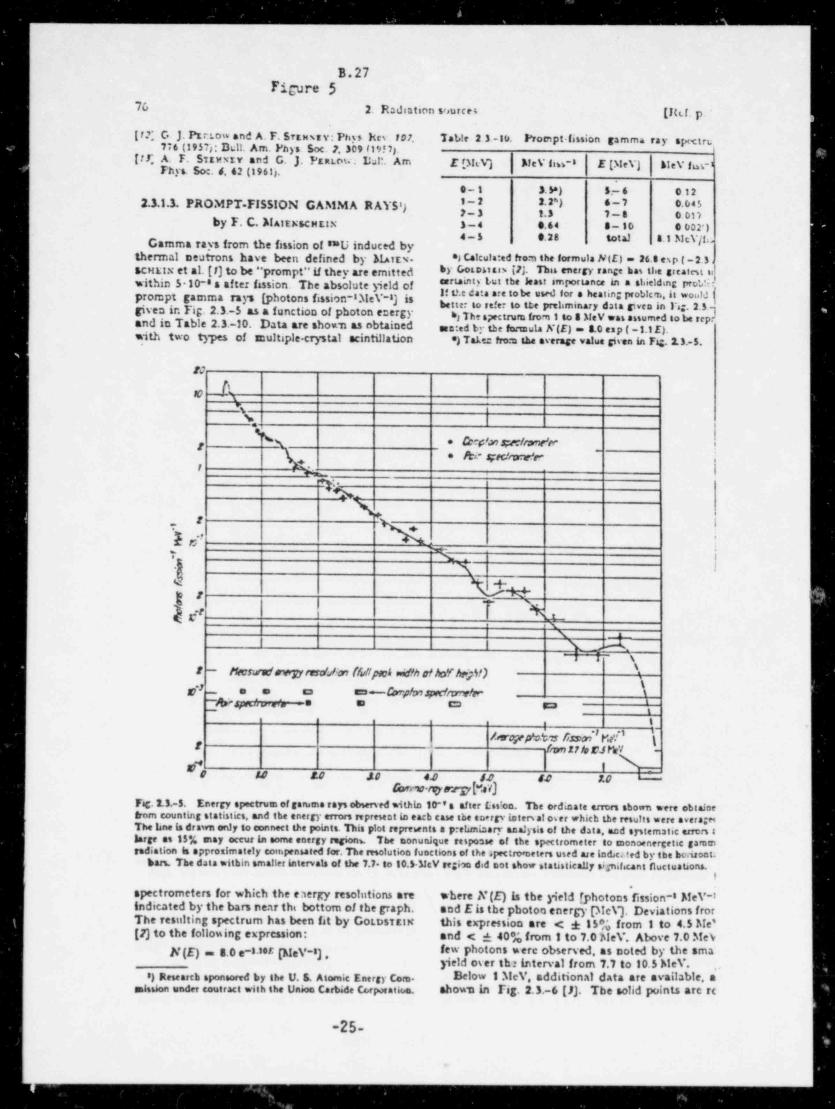
_ _ _ _ _ _ _ _ _ _ _ _ _ _ _ _ _ _ _ _ _ _ _ _ _ _ _ _ _ _ _ _ _ _ -
B.27Ficure 5
76 2. Radiation sources [Ikt. p.
[r.$ G J. Pzrrow and A. F. Sitney: Pnys her.107 Tat,te 2 3 -10. Prompt fission gamma ray spxtru776 (1957): All. Am. Phys Soc. 2. 309 f19'7).
[tC A. F. Stanty and G. J. Pznw hit Am E p!M NeV fm-8 E (MeV) blev i s -1Fhys. Soc.d. 62 (1961).
e-t 3. 9) s-s e 12
2.3.1.3. PROMPT. FISSION GAMMA RAYS') '[2 ) 6Zg
by F. C. MAltEsCMttN 3-4 e.64 s-to e o02')4-5 0.28 total 4.1 McV/foCamma rays from the fission of **U induced by
thermal neutrons have been defined by Mutx- *3 C*tcuta:ed trom the formula NIO - 26.s esp t-2.3.SCHEIN et al. (I) to be " prompt"if they are emitted by Gosoutb [4 Du energy range bn llee greaten siwithin 510-ss after isssion. The absolute yield o ennasty true the hut inwrtance in a sideldmg promprompt gamma rays (photons fission-83te\.-8) a.f
better to refer to ste prel minary data gwen in Fig. 2.5){If t?.e data are tobe used for a heating probics,it would
sgiven in Fig. 2.3.-5 as a function of photon energy *, The spectrum from 1 to a MeV was mumed to be repand in Table 2.3.-10. Data are shomm as nbtained een:ed ty the formula N(E) = 8.0 esp (-1.1 E).with two types of snultiple-crystal scintillat. ion *) Take: fro.a the average value given in Fig. 2.3.-5.
1
WQ R
%, I
k * (cepW.ipedeWer-S gic/mW=
*%-T%~\
t.
? 1. f. 'T -
*2
T +x,
I, ,
s\ 1
^
\\! - /teswatf avrytard/m (funpmi enifh & hoYk$) \
*2 e e ca en~ Carp'mapdwrs'er'g -
pg .c., e a cm s:a,
e t.
hvejefo$s Assd'Me'i' \f farth rJMrY -
I \sr*o Iu .o .no u u u u -
G>rrw-rigya:rpf.sV]Fig. 2.3.-5. Energy spectrum of gevuma rays observed Mthin 10-'s after f.:ss*on. The ordinate errors shown were obtainetrorn counting statistics. and the energy errors represent in each case the energy inters at os er which the results were averagesThe hne is drawn only to connect the points. His plot reprewnts a pretanisary analysis of the data, and sTitematic errorslarge es 15y, may occur in some energy regionw The monunique response of the spectrometer to monoenergetic garamradiation is approdmstely compensated for.The resolution functions of the spectro neters used are todeca ted by abe bedsont.
bars. The data within smaller intervals of the 7.7. to 10.54fcV regbo did not show statistica!Jy significant fluctuations.t
'
spectrometers for which the eaergy resolutions are where N(E) is the yield [ photons fission-8 AfeV-'indicated by the bars near ths bottom of the graph. and Eis the photoo energy pleV). Deviations frorThe resulting spectrum has been fit by Gotosittn this expression are < * IPA from 1 to 4.5 Me'[7] to the following expression: and < a 4084 from 1 to 7.0 MeV. Above 7.0 Stev
hfew P otons were observed, as noted by the smaN(E) - 8.0 e-8 8er (h!eV-8} * yield oser the interval from 7.7 to 10.5 Me\. ,
) Research sponsored by the U. S. Atomic Energy Com. Below 1.TIcV additional data are available. asaiulon under ecutract with the Union Cartsde Cr,rporation. shows in Fig. 2.3.-6 [JJ. The solid points are rc
-25-
,
a
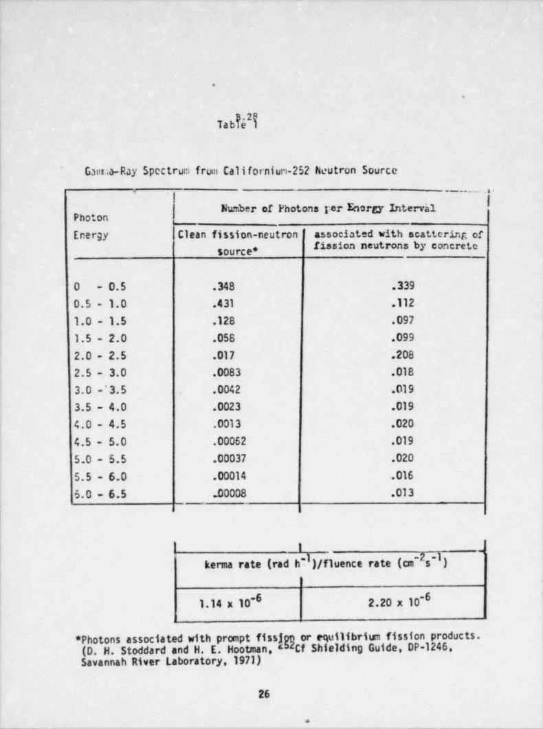
__
.
.
!
Tabid $
Ganua-Ray Spectrum from Californiun-252 Neutron Source'
5 - - . . . . . . . -
Number of Photons rer Energy Intervh1Photon
; Energy Clean fission-neutron ' associated with scattering orfission neutrons by concrete
| source *1
0 - 0.5 .348 .339
0.5 - 1.0 .431 .112
1.0 - 1.5 .128 .097
1.5 - 2.0 .058 .099
2.0 - 2.5 .017 .208
| 2.5 - 3.0 .0083 .018
3.0 ~3.5 .0042 .019.
3.5 - 4.0 .0023 .019
4.0 - 4.5 .0013 .020s
4.5 - 5.0 .00062 .019
5.0 - 5.5 .00037 .020
5.5 - 6.0 .00014 .016
6.0 - 6.5 .00008 .013
1 .
-2 -I)kerma rate (rad hd)/fluencerate(cm s
1.14 x 10⁻⁶ 2.20 x 10⁻⁶-
*Photonsassociatedwithpromptfissj or equilibrium fission products.(D. H. Stoddard and H. E. Hootman, Cf Shielding Guide DP-1246,Savannah River Laboratory,1971)
26
. ..
5.29
Report on the On-Site Inspection of the Irradiation Geometries and Procedures
to be Used by the University of Michigar.'s School of Public Healthfor the Third Pilot Study of Personnel-Dosimetry Performance
r .
,
9
i
.
)'
in fulfillment of the requirements of Contract No. NRC-01-80-023 (and; modification 01) between the Nuclear Regulatory Conmission and thei National Bureau of Standards,
;
j
$
l
) ,
5
October 28, 198131
;
j
!! .
!
l
i
i- . - . . - - , . - . . . .--.--.... - -..-. , - - - . , . . - - . . , . _ . - . - - - . -.,.
B.30
Report on the On-Site Inspection of'the Irradiation Geometries and Proceduresto be Used by the University of Michigan's School of Public Health
for the Third Pilot Study of Personnel-Dosimetry Performance
kovdetur v- -
C. Eisenhauer, Rediation Theory T. Loftus, R iation Dosimetry(neutrons, radiation sh'ielding) (photons)
,
L
f \V # ^1
7Q . \ |,by? v, * hnill li0*
k.)r'uitt',RadiationDosimetry M.Ehriich,radiationDosimetry(betaparticles) (Contract-Liaison Officer)
:
i
October 28, 1981
Date
.
9
,
-. . - . ..-- - - - - .--. - . . , - - - - - -
. , - - ---- . - . - - - - - -
. . __
4
'
B.31
1. Introduction
As specified .in the Interagency Agreement of September 5,1980, extended on'
September 23,1981 (contract No. NRC-01-80-023 and modification 01) between the
Nuclear Regulatory Comission (NRC) and the National Bureau of Standards (NBS).
NBS performed an on-site inspection of all radiation facilities of the University of
Michigan School of Public Health that will be used in the third pilot study, and
examined irradiation geometries and irradiation and dosimeter-handling procedures.
This inspection was necessary prior to the start of the third pilot study because of ,
I.
| the extensive changes that had been made since the last pilot study in the radiation- '
source setups and in the personnel that was 'to be involved.
i;
) The inspection took place on October 5,1981 and involved three NBS)
i staff members. After their return to NBS, they discussed and reviewed their findings4
*
i in detail with the NBS contract-liaison officer who in turn discussed still ques-:
i tionable points with the contractor by telephone. In the following, an account isi
given on the findings of the inspection team; recommendations are made regarding
} modifications and additions desired or required prior to and after the start of the;
j active phase of the third pilot study; and plans are detailed for the envisaged NBS
| measurement-assurance studies.i
1,
2. Fonnat of Inspection
} The following three NBS staff members spent the day of October 6 with the]4- contractor:
j C. Lisenhauer, Nuclear Radiation Division, as the expert on
i neutron physics and radiation shielding;
.1
'1
i
. _ _ _ - _ . . _ . - . - . - --. - - - - . - - . -- . . . . - . - - . _ - - -
-_ - - _ _ _ _ _ _ _ - _ _ _ _ - _ _ _
B.32
T. Loftus, Radiation Ph.vsics Division, as the expert on photon dosimetry;
J. Pruitt, Radiation Physics Division, as the expert on beta-'
particle dosimetry.
These NBS staff members (later on referred to as the " inspection team") visited the,
bremsstrahlung irradiation facilities (still in room M 6150, Building SPH II, and
rcom SB 171, Building SPH I); the beta-particle irradiation facility (still in room
M 6333, Building SPH II); the new 2"Cs gama-irradiation facilities (at the former
Willow Run Air Force Base Building No. 2208, later referred to as the Gama-Ray
Building); and the neutron-irradiation facifity (at the fonner Willow Run Air Force
Base Building No. 2209, later referred to as the Neutron Building), newly equipped
with a D20-moderated neutron source.
The inspection team came equipped with a list shown in Table 1, prepared by the
NBS contract-liaison officer, of the major points to be covered in the current
inspection. They were then handed an outline by the contractor of the work already
completed by the contractor on the installation and standardization of the new or
newly modified facilii.ies, including sketches of the layout of these facilities, and
an outline of the work not as yet completed. (See table 2 and figures 1 and 2.)
3. Findings of Inspection Team
3.1 Staff
Prof. Phillip Plato, acting chairman, Department of Environmental
Health, again will be in charge of the pilot study. His staff on this projectwill consist of
l
2
.
B.33.
Joe Miklos, research investigator; with the program since June, 1980;
master's degree from U. of Michigan School of Public Health, June,1980;
undergraduate major: biology.
!
Roberta Purdon, technician; with the program since September 1,1981;
working on master's degree in Public Health; had experience with
Parke Davis for 26 years.
| Tim Almburg, technician; with the program since September 1, 1981;
bachelor's degree in physics. ,
1
1
There also will be two part-time persons, both students working
on their master's degree. Richard Nevil (Health Physics) again is
i assisting with the various radiatien-protection aspects, particularly
around the neutron source.
The NBS team considers the staffing to be adequate for the
task at hand.
| 3.2 General Procedures
3.2.1 Beam standardization and dosimeter irradiation.
!
The procedures followed, including the logistics of dosimeter flow
through the facilities, are in most parts similar to the ones followed
! during the two former pilot studies, except for the variations necessitated
by the change in general layout (see section 2). At the time of the
3
.. .. . .- . _ . __ __
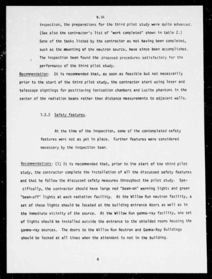
_ _ _ .
. .
_. - _ _ _ _ _ _ _ _ _ _ _ _ _ _ _ _ . _
B.34
inspection, the preparations for the third pilot study were quite advanced.
(See also the contractor's list of " work completed" shown in table 2.)
Some of the tasks listed by the contractor as not having been completed,
such as the mounting of the neutron source, have since been accomplished.
The inspection team found the proposed procedures satisfactory f or they
performance of the third pilot study.
Reconnendation: It is recommended that, as soon as feasible but not necessarily:.
prior to the start of the third pilot study, the contractor start using laser and
telescope sightings for positioning ionization chambers and Lucite phantoms in the
center of the radiation beams rather than distance measurements to adjacent walls.
3.2.2 Safety features.
At the time of the inspection, some of the contemplated safety
features were not as yet in place. Further features were considered
necessary by the inspection team.
' Recommendations : '(1) It is recommended that, prior to the start of the third pilot
study, the contractor complete the installation of all the discussed safety features
and that he follow the discussed safety measures throughout the pilot study. Spe-
cifically, the contractor should have large red " beam-on" warning lights and green
" beam-off" lights at each radiation facility. At the Willow Run neutron facility, a
set of these lights should be located at the building entrance doors as well a's in
the immediate vicinity of the source. At the Willow Run gamma-ray facility, one set
of lights should be installed outside the entrance to the shielded rooms housing the
gamma-ray sources. The doors to the Willow Run Neutron and Gamma-Ray Buildings
should be locked at all times when the attendant is not in the building.
4
___
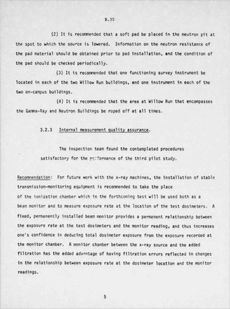
_ _
B.35
(2) It is recomended that a soft pad be placed in the neutron pit at
the spot to which the source is lowered. Information on the neutron resistance of
the pad material should be obtained prior.to pad installation, and the condition of'
the. pad should be checked periodically.
(3) It is recomended that one functioning survey instrument be
lecated in each of the two Willow Run buildings, and one instrument in each of the
two on-campus buildings.
(4) It is recomended that the area at Willow Run that encompasses
the Gama-Ray and Neutron Buildings be roped off at all times.
3.2.3 Internal measurement quality assurance.,
!
The inspection team found the contemplated procedures-
satisfactory for the performance of the third pilot study.
Recomendation: For future work with the x-ray machines, the installation of stable
transmission-monitoring equipment is recomended to take the place
of the ionization chamber which in the forthcoming test will be used both as a
beam monitor and to measure exposure rate at the location of the test dosimeters. A:
fixed, permanently installed beam monitor provides a permanent relationship between
the exposure rate at the test dosimeters and the monitor reading, and thus increases.
one's confidence in deducing total dosimeter exposure from the exposure recorded at
; the monitor chamber. A monitor chamber between the x-ray source and the added
filtration has the added advantage of having filtration errors reflected in changes
in the relationship between exposure rate at the dosimeter location and the monitor
readings.
5
_ _ _ _ _ . . _ _ . - - - - . - - . . -- - -- . _ _ _ _ _ _ _ _ _ - . _ . .. _
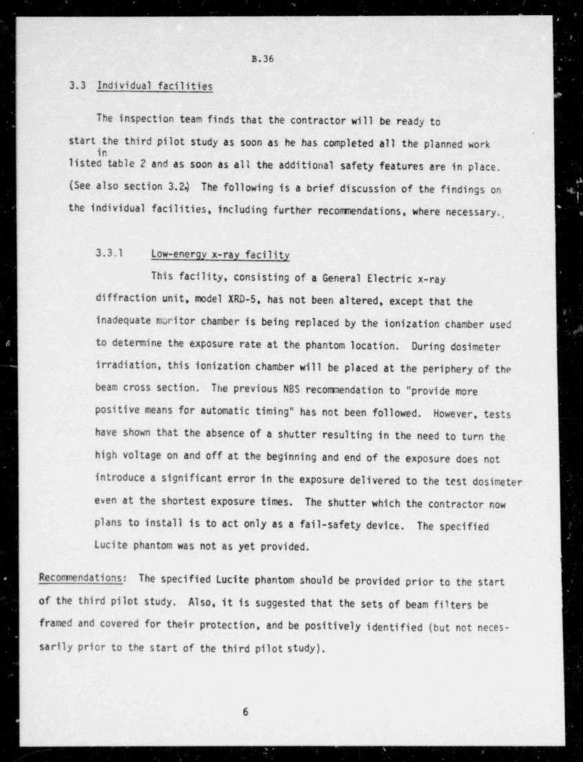
__ _ _ _ _ _ _ _ - _ _ _ _
B.36
3.3 Individual facilities
The inspection team finds that the contractor will be ready to
start the third pilot study as soon as he has completed all the planned workin
listed tabic 2 and as soon as all the additional safety features are in place.
(See also section 3.2.) The following is a brief discussion of the findings on
the individual facilities, including further recomendations, where necessary.,
3.3.1 Low-energy x-ray facility
This facility, consisting of a General Electric x-ray
diffraction unit, model XRD-5, has not been altered, except that the
inadequate monitor chamber is being replaced by the ionization chamber used
to determine the exposure rate at the phantom location. During dosimeter
irradiation, this ionization chamber will be placed at the periphery of the
beam cross section. The previous NBS recomendation to " provide more
positive means for automatic timing" has not been followed. However, tests
have shown that the absence of a shutter resulting in the need to turn the
high voltage on and off at the beginning and end of the exposure does not
introduce a significant error in the exposure delivered to the test dosimeter.
even at the shortest exposure times. The shutter which the contractor now
plans to install is to act only as a fail-safety device. The specified
Lucite phantom was not as yet provided.
Recomendations: The specified Lucite phantom should be provided prior to the start
of the third pilot study. Also, it is suggested that the sets of beam filters be
framed and covered for their protection, and be positively identified (but not neces-
sarily prior to the start of the third pilot study).
6
. _ - _ _ _ - _ _ ___ _ _ _ _
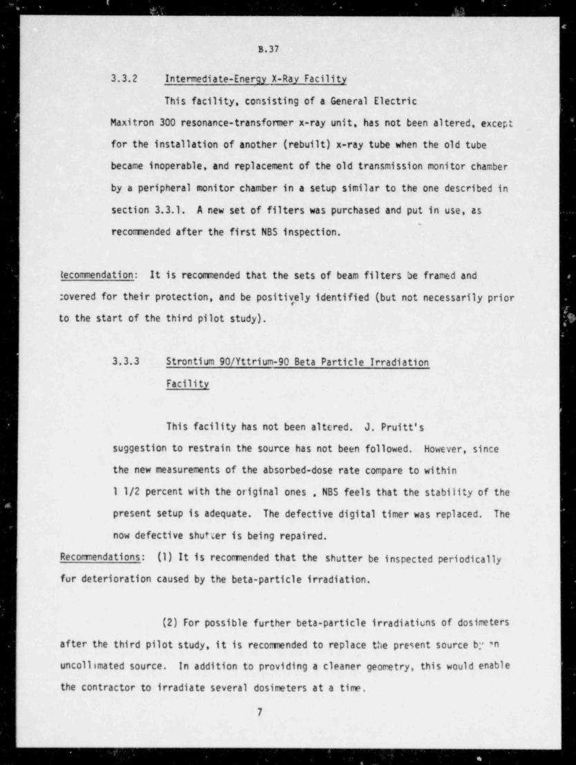
B.37
3.3.2 Intermediate-Energy X-Ray Facility
This facility, consisting of a General Electric
Maxitron 300 resonance-transformer x-ray unit, has not been altered, except
for the installation of another (rebuilt) x-ray tube when the old tube
became inoperable, and replacement of the old transmission monitor chamber
by a peripheral monitor chamber in a setup similar to the one described in
section 3.3.1. A new set of filters was purchased and put in use, as-
recomended after the first NBS inspection.
tecommendation: It is recomended that the sets of beam filters be framed and
: overed for their protection, and be positively identified (but not necessarily prior
to the start of the third pilot study).
3.3.3 Strontium 90/ Yttrium-90 Beta Particle Irradiation
Facility
This facility has not been altered. J. Pruitt's
suggestion to restrain the source has not been followed. However, since
the new measurements of the absorbed-dose rate compare to within
11/2 percent with the original ones , NBS feels that the stability of the
present setup is adequate. ~ The defective digital timer was replaced. The
now defective shutter is being repaired.
Recommendations: (1) It is recomended that the shutter be inspected periodically
for deterioration caused by the beta-particle irradiation.
(2) For possible further beta-particle irradiatiuns of dosimeters
after the third pilot study, it is recommended to replace the present source by 'n
uncollimated source. In addition to providing a cleaner geometry, this would enable
the contractor to irradiate several dosimeters at a time.
7
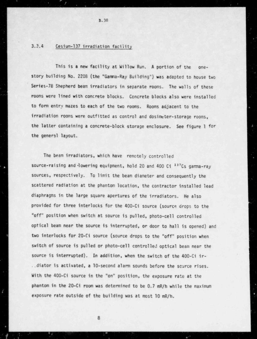
,__ - ____-____________ _ ._
B.38
- .
3.3.4 Cesium-137 irradiation facility
This is a new facility at Willow Run. A portion of the one-
story building No. 2208 (the "Gama-Ray Building") was adapted to house two
' Series-78 Shepherd beam irradiators in separate rooms. The walls of these
rooms were lined with concrete blocks. Cencrete blocks also were installe'd
to form entry mazes to each of the two rooms. Rooms adjacent to the
irradiation rooms were outfitted as control and dosimeter-storage rooms,
the latter containing a concrete-block storage enclosure. See figure 1 for
the general layout.
The beam irradiators, which have remotely controlled
source-raising and-lowering equipment, hold 20 and 400 C1 237Cs gama-ray
sources, respectively. To limit the beam diameter and consequently the
scattered radiation at the phantom location, the contractor installed lead
diaphragms in the large square apertures of the irradiators. He also
provided for three interlocks for the 400-Ci source (source drops to the
"off" position when switch at source is pulled, photo-cell controlled
optical beam near the source is interrupted, or door to hall is opened) and
two interlocks for 20-Ci source (source drops to the "off" position when
switch of source is pulled or photo-cell controlled optical beam near the
source is interrupted). In addition, when the switch of the 400-Ci ir-
._diator is activated, a 10-second alarm sounds before the scurce rises.
With the 400-Ci source in the "on" position, the exposure rate at the
phantom in the 20-Ci room was detemined to be 0.7 mR/h while the maximum
exposure rate outside of the building was at most 10 mR/h.
8
__ . .. _ _ _ _ _ _ _ _ _ _ _ _ _ _ _ _ _ _ _ _ _ _ _ _ _ . _ _ _
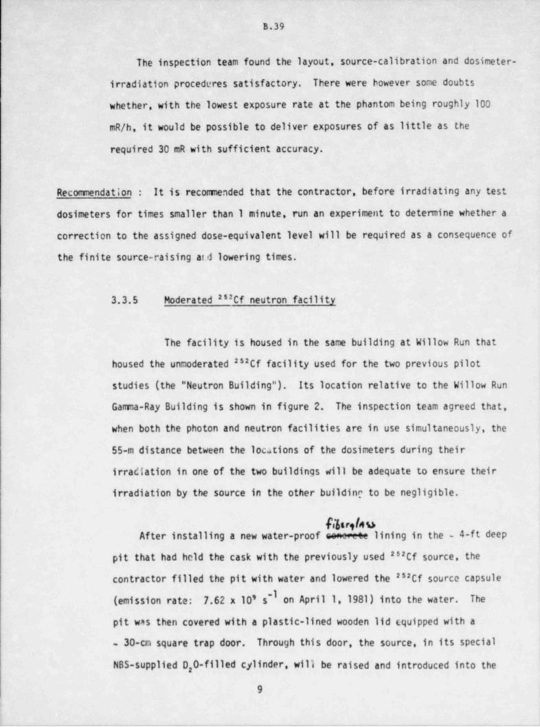
m
B.39
The inspection team found the layout, source-calibration and dosimeter-
irradiation procedures satisfactory. There were bowever some doubts
whether, with the lowest exposure rate at the phantom being roughly 100
mR/h, it would be possible to deliver exposures of as little as the
required 30 mR with sufficient accuracy.
Recommendation : It is recomended that the contractor, before irradiating any test
dosimeters for times smaller than 1 minute, run an experiment to determine whether a
correction to the assigned dose-equivalent level will be required as a consequence of
the finite source-raising and lowering times.
3.3.5 Moderated as:Cf neutron facility
The facility is housed in the same building at Willow Run that
housed the unmoderated as2Cf facility used for the two previous pilot
studies (the " Neutron Building"). Its location relative to the Willow Run
Gama-Ray Building is shown in figure 2. The inspection team agreed that,
when both the photon and neutron facilities are in use simultaneously, the
55-m distance between the locations of the dosimeters during their
irradiation in one of the two buildings will be adequate to ensure their
irradiation by the source in the other buf1 ding to be negligible.
Obr 9/44After installing a new water-proof senece+e lining in the 4-ft deep
pit that had hcid the cask with the previously used as2Cf source, the
contractor filled the pit with water and lowered the as:Cf source capsule
(emission rate: 7.62 x 10' s'I on April 1,1981) into the water. The
pit was then covered with a plastic-lined wooden lid (quipped with a
30-cm square trap door. Through this door, the source, in its special
NBS-supplied D,0-filled cylinder, will be raised and introduced into the
9
4
- - - _ . , - . _ --
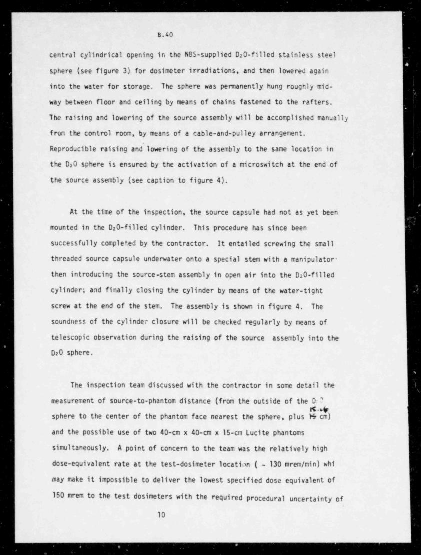
- _ _ _ _ _ _ . _ _ _
B.40
central cylindrical opening in the NBS-supplied D20-filled stainless steel
sphere (see figure 3) for dosimeter irradiations, and then lowered again
into the water for storage. The sphere was permanently hung roughly mid-
way between floor and ceiling by means of chains fastened to the rafters.
The raising and lowering of the source assembly will be accomplished manually
from the control room, by means of a cable-and-pulley arrangement.
Reproducible raising and lowering of the assembly to the same location in
the D20 sphere is ensured by the activation of a microswitch at the end of
the source assembly (see caption to figure 4).
At the time of the inspection, the source capsule had not as yet been
mounted in the D20-filled cylinder. This procedure has since been
successfully completed by the contractor. It entailed screwing the small
threaded source capsule underwater onto a special stem with a manipulator-
then introducing the source-stem assembly in open air into the D20-filled
cylinder; and finally closing the cylinder by means of the water-tight
screw at the end of the stem. The assembly is shown in figure 4. The
soundness of the cylinder closure will be checked regularly by means of
telescopic observation during the raising of the source assembly into the
D20 sphere.
The inspection team discussed with the contractor in some detail the
measurement of source-to-phantom distance (from the outside of the D:'g.4
sphere to the center of the phantom face nearest the sphere, plus M cm)
and the possible use of two 40-cm x 40-cm x 15-cm Lucite phantoms
simultaneously. A point of concern to the team was the relatively high
dose-equivalent rate at the test-dosimeter location ( ~ 130 mrem / min) whi
may make it impossible to deliver the lowest specified dose equivalent of
150 mrem to the test dosimeters with the required procedural uncertainty ofw I
|
10
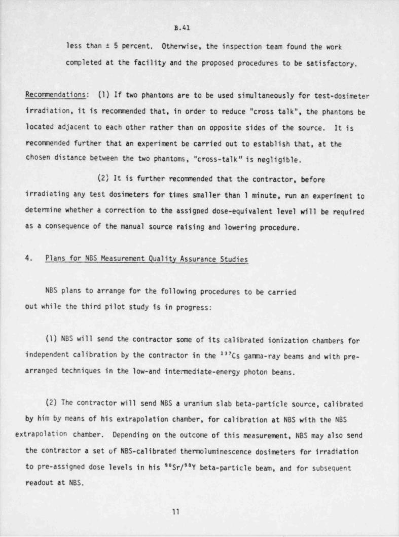
B.41
less than 5 percent. Otherwise, the inspection team found the work
completed at the facility and the proposed procedures to be satisfactory.
Rtconinendations: (1) If two phantoms are to be used simultaneously for test-dosimeter
irradiation, it is recommended that, in order to reduce " cross talk", the phantoms be
lccated adjacent to each other rather than on opposite sides of the source. It is
recomended further that an experiment be carried out to establish that, at the
chosen distance between the two phantoms, " cross-talk" is negligible.
(2) It is further recommended that the contractor, before
irradiating any test dosimeters for times smaller than 1 minute, run an experiment to
determine whether a correction to the assigned dose-equivalent level will be required
as a consequence of the manual source raising and. lowering procedure.
4. Plans for NBS Measurement Quality Assurance Studies
i NBS plans to arrange for the following procedures to be carried
cut while the third pilot study is in progress:
(1) NBS will send the contractor some of its calibrated ionization chambers for
independent calibration by the contractor in the "7Cs gama-ray beams and with pre-
arranged techniques in the low-and intennediate-energy photon beams.
(2) The contractor will send NBS a uranium slab beta-particle source, calibrated
by him by means of his extrapolation chamber, for calibration at NBS with the NBS
extrapolation chamber. Depending on the outcome of this measurement, NBS may also send
the contractor a set of NBS-calibrated thermoluminescence dosimeters for irradiation
to pre-assigned dose levels in his "Sr/"Y beta-particle beam, and for subsequent
readout at NBS.
11
-__ _ _. .
__ - ._- - _ - ______ _ _ _ _ _ _ _ _ _ _ _ _
'
|
B.42
The performance of the contractor will be judged by the extent of agreement
with NBS measurements. No neasurement-quality assurance study will be
done for the moderated as:Cf neutron facility for which NBS supplied
both the standardized source and the D20 moderator.
5. Conclusions and Disposition
.
The contractor has done a considerable amount of good work in
preparation for the third pilot study and will be ready to start some of
the test-dosimeter irradiations on November A ,1981, or soon thereafter.
NBS will consult by telephone with the contractor on the progress of the
work yet to be completed on each of the irradiation facilities, and will
advise the NRC as soon as the test-dosimeter irradiations may connence
on a particular facility.
12
- _ - _ _ _ _ _ .. ____ _ _____ _ ___________n
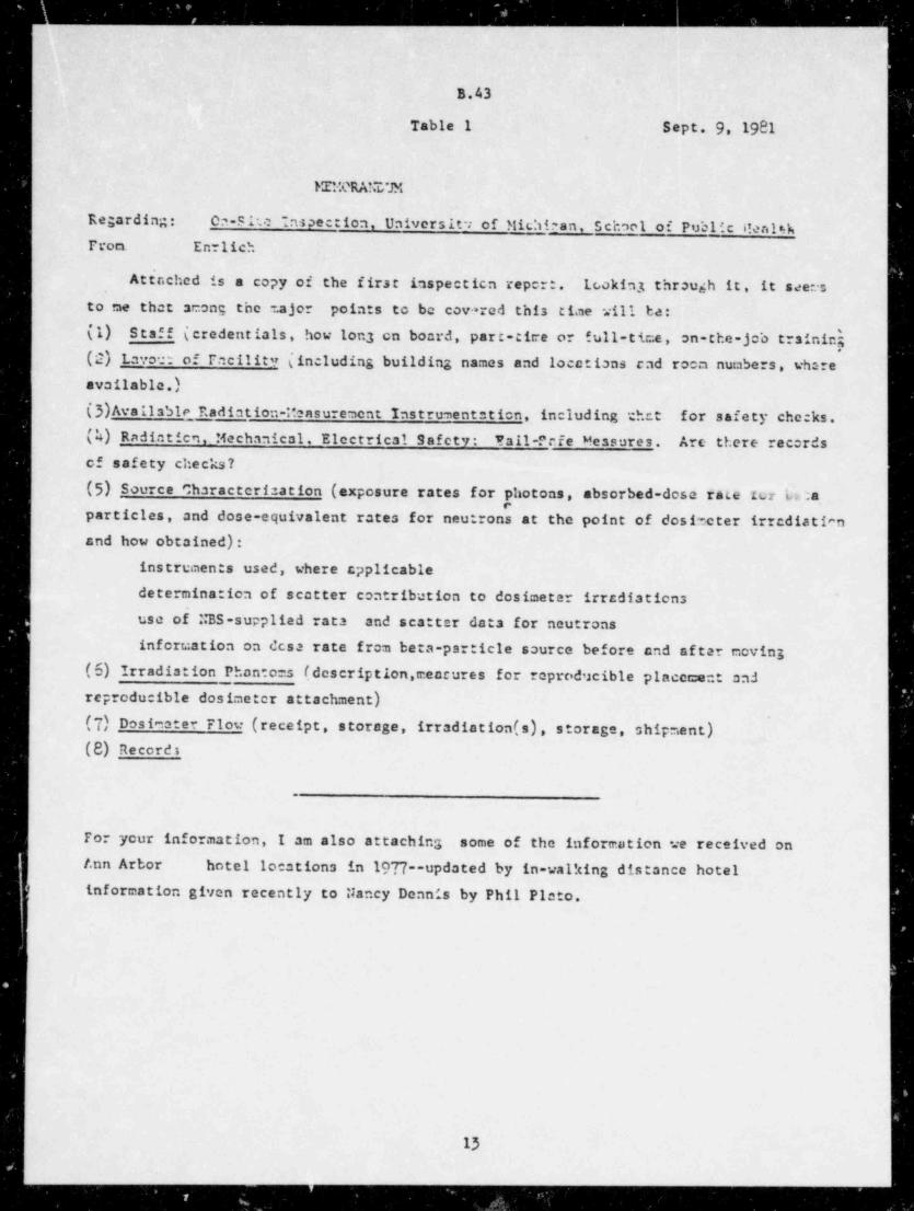
_ . _ _ _ _ _ _ _ _ _ _ _ _ _ _ _ _ - _ _ _ _ _ _ _ _ _ _ _ _ __ __.
. .
,
B.43
Table 1 Sept. 9, 1981,
ME:TRAhT/JM
Regarding: On-site nspection. Universit : of Michican, school of Public i!en14hFrom. En lich
~
Attnched is a copy of the first inspectica repert. Lookin3 through it, it seeres
to me that acong the ajor points to be cov> red this time will ba:
(1) Staf f (credentials, how lon3 cn board, part-cire or full-time, on-the-job trainich(2) Lavor: of Facility (including building names and locations cad room numbers, whsrecvailable.)(3)Avalls51e Radiation-Ibasurement Instrumentation, including *chet for safety checks.(k) Radiatien. Mechanical. Elcetrical Safety: Yall-Pcie Messures. Are there recordsof safety checks?
(5) Source characterisation (exposure rates for photons, absorbed-dose rate rcr L.:aparticles, and dose-equivalent rates for neutrons at the point of dosincter irrediatianand how obtained):
instruments used, where cpplicable
determination of scatter contribution to dosimeter irradiations ~
useo$NBS-suppliedrata and scatter data for neutrons
information on dcsa rate from beta-particle source before and after moving(6) Irradiation Phantoms (description,mencures for reproducible placement andreproducible dosimeter attachment)
(7) Dosiester Flow (receipt, storage, irradiation (s), storage, shipment).
(8) Recordt
.
For your information, I am also attaching some of the information we received on/.nn Arbor hotel locations in 1977--updated by in-walking distance hotel
) information given recently to Nancy Dennis by Phil Picto.
13
. .
_ _ _ . _
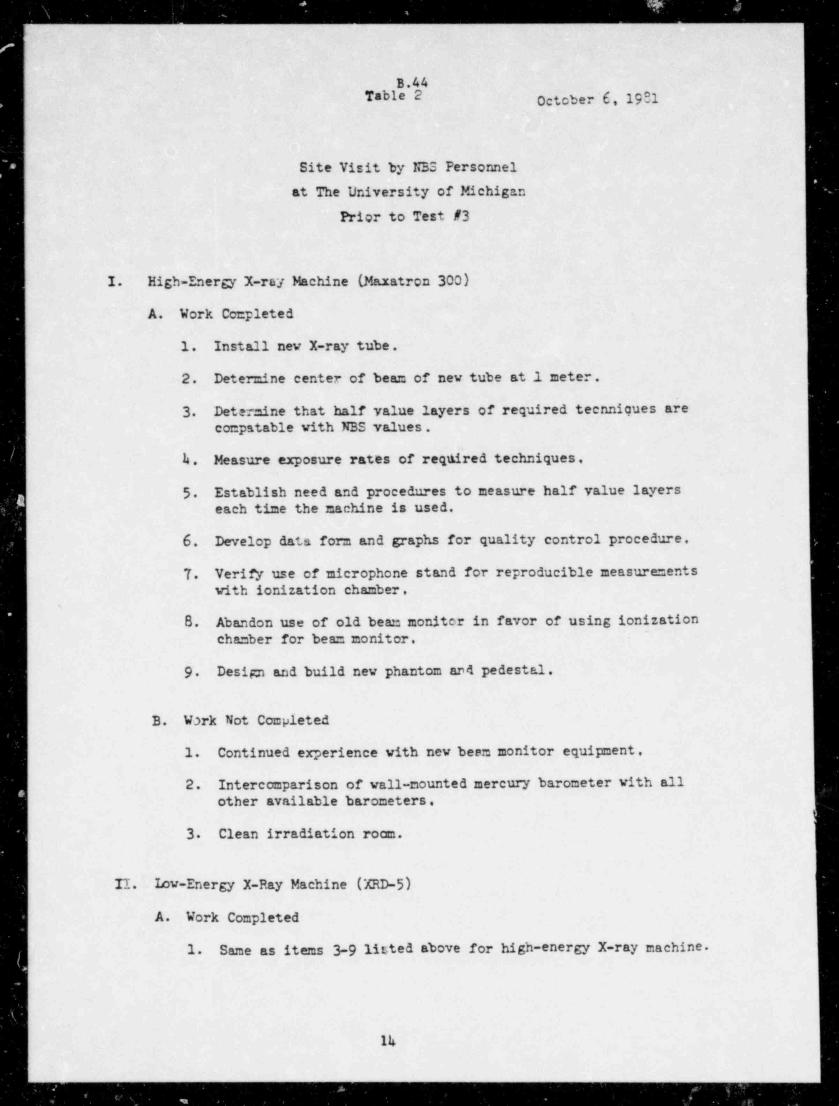
(_-_ _ _ _ _ _ _ _ _ _ - _ _ _ _ _ _ _ _ _ _ _ _ _ _ _ _ _ _
B.44Table 2 October'6, 1981
Site Visit by N35 Personnel
at The University of Michigan
Prior to Test #3
1. High-Energy X-ray Machine (Maratron 300)
A. Work Completed
1. Install nev X-ray tube.
2. Deter =ine center of bea= of new tube at.1 meter.
3 Deter =ine that half value layers of required teenniques areco=patable with NBS values.
k. Measure exposure rates of reqtired techniques.
5 Establish need and procedures to measure half value layerseach time the nachine is used.
6. Develop data form and graphs for quality control procedure.
7. Verify use of nicrophone stand for reproducible measure =entswith ionization chamber.
B. Abandon use of old beam moniter in favor of using ionization
cha=ber for bea= monitor.
9 Desip and build new phantom and pedestal.
B. W3rk Not Completed
1. Continued experience with new been monitor equipment.
2. Intercomparison of vall-mounted mercury barometer with allother available barometers.
:
3 Clean irradiation room.
II. Iow-Energy X-Ray Machine (XRD-5)
A. Work Completed
1. Same as items 3-9 listed above for high-energy X-ray machine.
Ik
-- - _ _ _ _ _ _ _ _ _ _ _ _ _ _ _ _ _ _ _ _
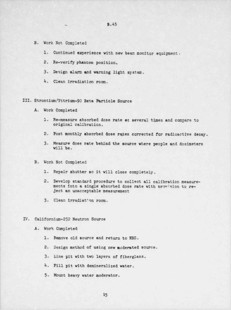
B.45m
B. Work Not Completed
1. Continued experience with new beam monitor equipment .
2. Re-verify phantom position.
3. Design alam and warning light system,
b. Clean irradiation room..
III. Strontium / Yttrium-90 Beta Particle Source
A. Work Completed
1. Re-measure absorbed dose rate at several times and compare tooriginal calibration.
2. Post monthly absorbed dose rgtes corrected for radioactive decay.
3 Measure dose rate behind the source where people and dosimeterswill be.
B. Work Not Completed
1. Repair shutter so it vill close completely.
2. Develop standard procedure to collect all calibration measure-ments into a single absorbed dose rate with trovision to re-ject an unacceptable measurement
3 Clean irradiation room.
IV. Californium-252 Neutron Source
A. Work Completed.
1. Remove old source and return to NBS.
2. Design method of using new moderated source.
3. Line pit with two layers of fiberglass,
k. Fill pit with demineralized water.
5 Mount heavy water moderator.
!'
15
_ _ _ _ _ - - _ - - .- -
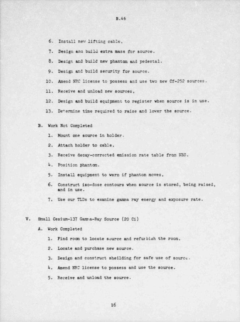
B.46
6. Inst?.11 nev lifting cable.
.
7. Desi5n ana build extra mass for source.
8. Design and build new phantom and pedestal.
9 Design and build security for source.
10. Amend NRC license to possess and use two new Cf-252 sources.
11. Receive and unload new sources,
12. Design and build equipment to register when source is in use,
13. De' ermine time required to raise and lover the source.
B. Work Not Completed
1. Motmt one source in holder.
2. Attach holder to cable.
3 Receive decay-corrected emission rate table from NBS,
k. Position Phantam.
5 Install equipment to warn if phantom moves,
6. Construct iso-dose contours when source is stored, being raised,- and in use .
7. Use our TLDs to examine gamma ray energy and exposure rate.
V. Small Cesium-137 Gamma-Ray Source (20 Ci).
A. Work Completed
1. Find roan to locate source and refurbish the room. ,
.
2. Locate and purchase new source.
3. Design and construct sheilding for safe use of source.
k. Amend NRC license to possess and use the source.i
l 5. Receive and unload the source.
~
16
. _
_ __ _ _ __
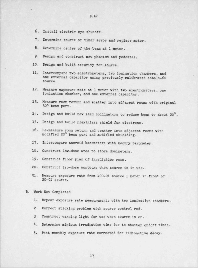
*,
B.47
6. Install electrie eye shutoff.
7. Determine source of timer error and replace motor.
8. Determine center of the beam at 1 meter.'
9 Design and construet new phantom and pedestal,
10. Design and build security for source. ,
' .
11. Intercompare two electrometers, two ionization chambers, and,
one external capacitor using previously calibrated cobalt-60 |source. !
'12. Measure exposure rate at 1 meter with two electrometers, one
ionization chamber, and one external capacitor.
13. Measure room return and scatter into adjacent rocas with original300 beam port.
} 1h. Design and build new lead collimators to reduce beam to about 20 .
15 Design and build plexiglass shield for electrons.
16. Re-measure room return and scatter into adjacent rooms withmodified 200 beam port and modified shielding.
{ 17. Intercompare aneroid barometers with mecury barometer.i
18. Construct low-dose area to store dostmeters.
19 Construct floor plan of irradiation room.
20. Construct iso-dose contours when source is in use.
21. Measureexposureratefrom$00-Cisource1meterinfrontof20-Ci source.
B. Work Not Completed,
i
1. Repeat exposure rate measurements with two ionization chanbers.
2. Correct sticking problem with source control rod.
3. Construct warning light for use when source is on.
h. Determine minicum irradiation time due to shutter on/off times.
; 5, Post monthly exposure rate corrected for radioactive decay.
.
17,
- - . -
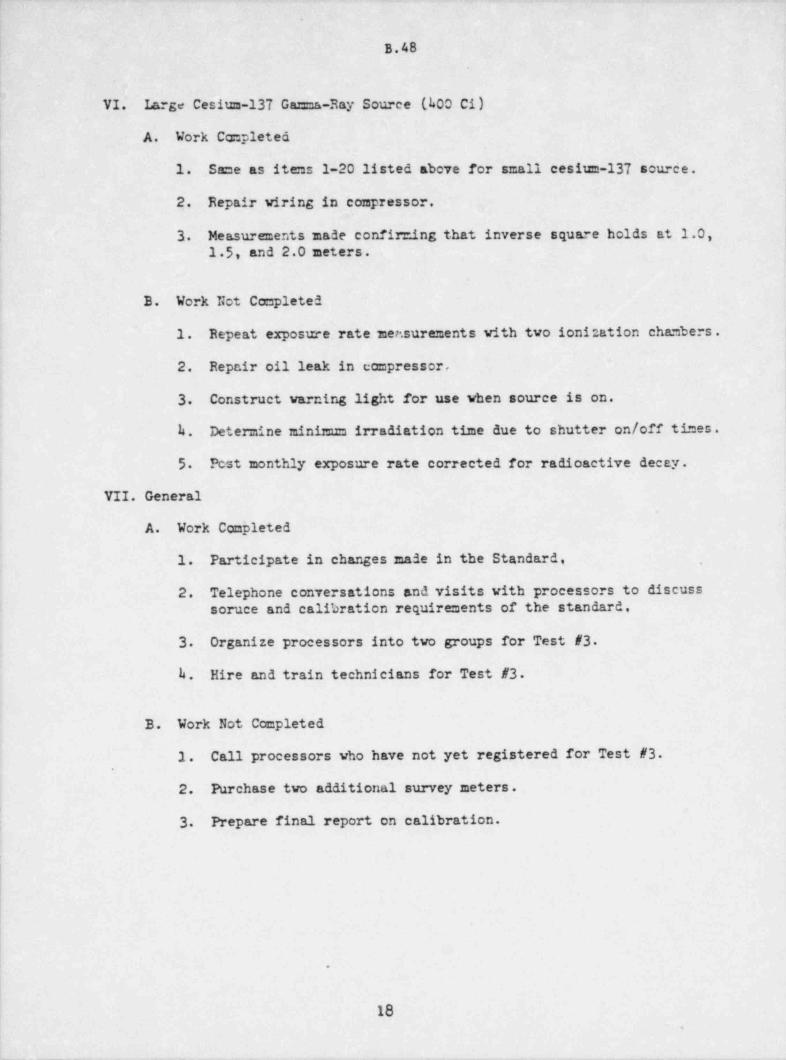
.
B.48
VI. Large Cesium-137 Gamma-Ray Source (kOO Ci)
A. Work Completed!| 1. Same as items 1-20 listed above for small cesium-137 source.'
!
| 2. Repair viring in compressor.
|3. Measurements made confire.ing that inverse square holds at 1.0,
1.5, and 2.0 meters.
3. Work Not Ceepleted
1. Repeat exposure rate mer.surements with two ionization chambers.
2. Repair oil leak in compressor,
3. Construct warning light for use when source is on.
h. Determine minMm irradiation time due to shutter on/off times.
5. Fest monthly exposure rate corrected for radioactive decay.
VII. General
A. Work Completed|
1. Participate in changes made in the Standard, ,
2. Telephone conversations and visits with processors to discusssoruce and calibration requirements of the standard,
3 Organize processors into two groups for Test #3
h. Hire and train technicians for Test #3
B. Work Not Completed
1. Call processors who have not yet registered for Test #3
2. Purchase two additional survey meters.
3 Prepare final report on calibration.
.
18.
_ _ - _
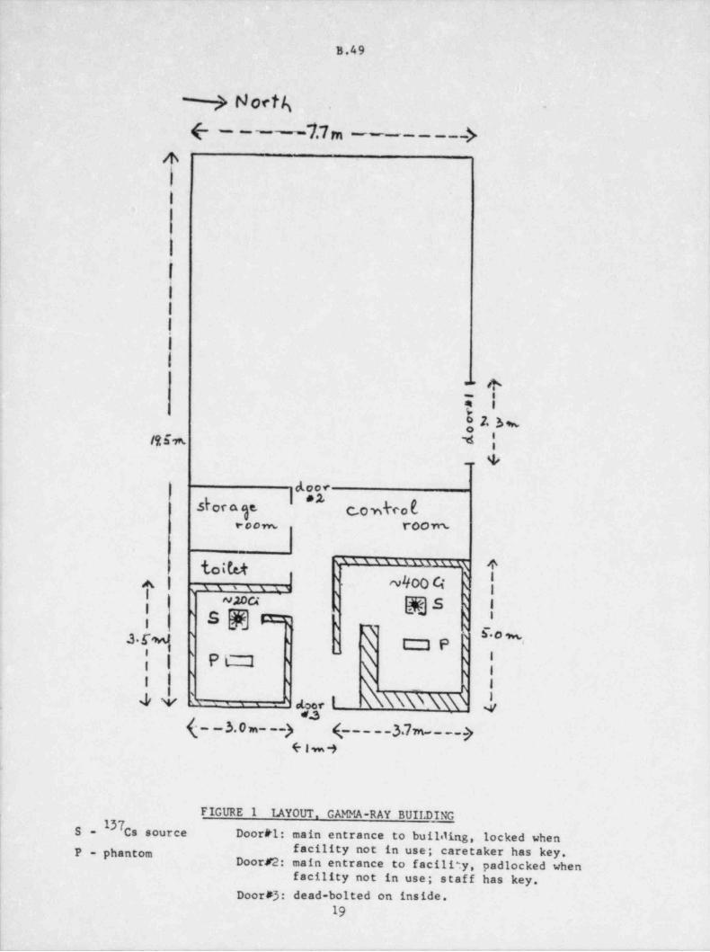
i
|B.49 |
-
> North -.
(- - - -7.7 m -- -- - - -->4
11 1
l:1
|
|
I
I
I
. . +7 i
|
l &a73%
Iti m. *i_ . +
|dOOf[ e 2,dora ge, C.Owkco b[
e c o ,w, r00vrs
1
' ' ' ' ' " " " " ' ') itotu t-
'A | - ~400 4 s i.s s ,s s .s
|l | @@ s R 1"maS [W] 8:52i & .'O Ses,
||: I s
s SMM ' s t3e s1
\|| |~
P L._2 s s
\ :i s-
i
44N $ a, i \ \\\NN\\\ d, ..
(- - 3. o m- --y (_____37m-__.__y(- l w -3
. ,
FIGURE 1 TAYOUT, GAMMA-RAY BUII. DING
S l37Cs source Door #1: main entrance to buililing, locked whenP - phantom facility not in use; caretaker has key.
Door #2: main entrance to facility, padlocked whenfacility not in use; staff has key.
Door #3: dead-bolted on inside.19
_ _ _ _ _ _ _ - - - __
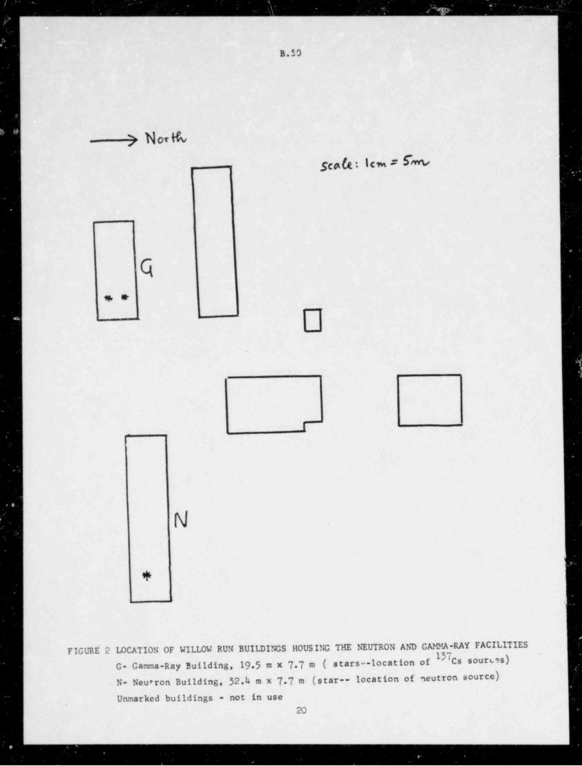
- - -- - ________-_ _
B.50
- ) N07bSce0. Icm # b
k. .
<-,
-
.
I
+
FIGURs 2 LOCATION OF WILLOW RUN BUILDINGS HOUSING THE NEUTRON AND GAMMA-RAY FACILITIES '137
G- Gamma-Ray Building,19 5 m x 7 7 m ( stars--location of cssoures)|
N- Neu.ron Building, 32.4 m x 7 7 m (star-- location of neutron source)e
Unmarked buildings - not in use20
-_
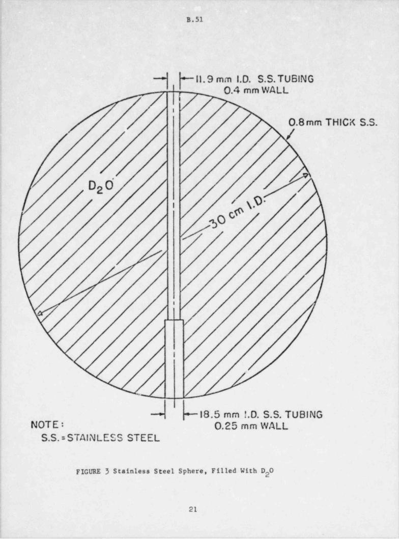
- . ..
B.51
~11.9 mm 1.D. S.S. TUBING-
O.4 mm WALL
/,
,
0.8 mm THICK S.S..
' D0.
2
- c@ \.9'i
!
i'
i
j .__.
,
i
; l
i
!
!| ~18.5 mm !.D. S.S. TUBING-
| NOTE: O.25 mm WALL: S.S.= STAINLESS STEEL
'
iI
FIGURE 3 Stainless Steel Sphere, Filled With D 02
;1
.
- _ _ _ _ . _ _ - - - - - - -- - - , .--- - ---
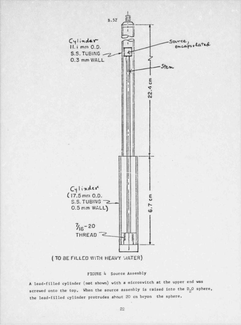
I
B.52 i
F'i oIi
bC 1imde.c mII. i mm O.D. [. %$$s,tated3
yS.S. TUBING y tTi
,O 7O.3 mm WALL'Wsp
.
Eu
I e,NN
I
1
.
1'
J i
I'
I
C 1iwM1( 17.5 mm 0.D. E
''S.S. TUBING 7O.5 mm WALL) N.
to
7/16-2OTHREAD 7 ,
' 1
f if
( TO BE FILLCO WITH HEAVY '.7ATER)
FIGURE i+ Source Assembly
A lead-filled cylinder (not shown) with a microswitch at the upper end wasscrewed onto the top. When the source assembly is raised into the D 0 sphere,2
the lead-filled cylinder protrudes about 20 cm beyon the sphere,t
22
- __ _ _ _ _ .. . ..
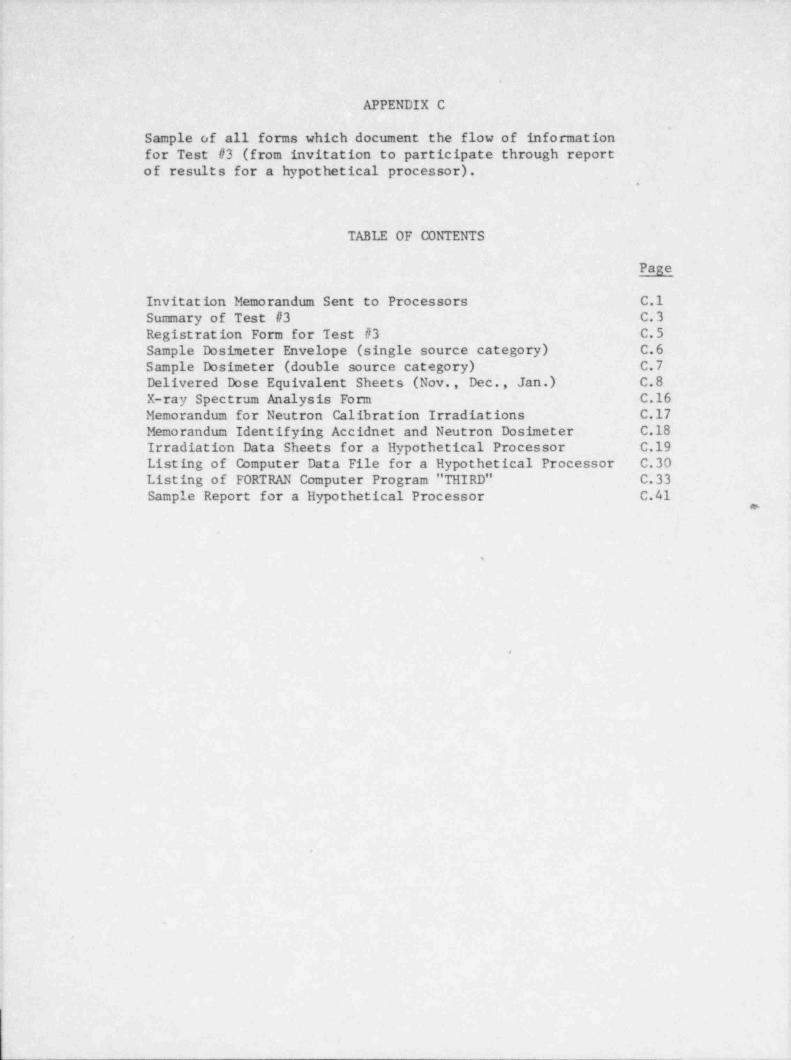
- - . .
.
A
. APPENDIX C
Sample of all forms which document the flow of information.. .
for Test #3 (from invitation to participate through reportof results for a hypothetical processor).
.
'
TABLE OF CONTENTSj
Page
i Invitation Memorandum Sent to Processors- C.1Sumary of Test #3 C.3Registration Form for Test #3 C.5 ;
Sample Dosimeter Envelope (single source category) C.6'
Sample Dosimeter (double source category) C.7Delivered Dose Equivalent Sheets (Nov., Dec., Jan.) C.8X-ray Spectrum Analysis Form C.16 ;
Memorandum for Neutron Calibration Irradiations C.17 |
Memorandum Identifying Accidnet and Neutron Dosimeter C.184
Irradiation Data Sheets for a Hypothetical Processor - C.19Listing of Computer Data File for a Hypothetical Processor C.30Listing of FORTRAN Computer Program " THIRD" C.'33Sample Report for a Hypothetical Processor C.41
o- >
<
%
J
<
t
'h I.
1
i
<
i
.
4
1
4
N
'
.
*
1
.
$.
- _ _ _ _ _
_ _ _ _ _ _ _ _ _ _ _ _ __
C.1THE UNIVERSITY OF MICHIGAN
SCHOOL OF Pusuc HEAuH
ANN AnsOn. MICHIGAN 48xosDepomnent of Emironmental
and Industrial Heahh
MEMORANDUMSeptember 1, 1981
TO: Personnel Dosimetry ProcessorsFROM: Phillip PlatoSU3J: Test #3 to HPSSC/ ANSI Standard
The Nuclear Regulatory Com=ission (NRC) published an Advanced Noticeof Rulemaking on Certification of Personnel Dosimetry Processors on March28,1981 (45 FR 20h93 to 20h96). The NRC is preparing to publish for commentproposed amendments to 10 CFR 20 that vill require licensees who must performpersonnel monitoring to "obtain the services of a dosimetry processor who hasbeen accredited by the Department of Commerce (DOC). Accreditation villinclude testing based on the. Standard, " Criteria for Testing PersonnelDosinetry Performance." This Standard was accepted by the Health PhysicsSociety Standards Committee (HPSSC) on June 23, 1981. The Standard is in thefinal review process prior to acceptance by the American National StandardsInstitute (ANSI). It is anticipated that A?ISI vill adopt the Standard inearly 1982, that a voluntary testing and accreditation program vill bei;in inmid-1982 administered by the National Voluntary Laboratory Accreditation
- Program (NVLAP) which is part of the DOC, and that the amendment discussedabove to 10 CFR 20 vill be completed by early 1983
The NRC contracted with the University of Michigan to conduct a pilotstudy of an early draft of this Standard beginning in 1977. The originalpurpose of the pilot study was to evaluate the Standard for field use. Tothat end, 59 dosimetry processors participated in two tests of the Standard.The procedures used, results obtained, and our recommendations werepublished as NUREG numbers CR-1063, CR-106h, CR-130h, and CR-1593 Additionalreports were prepared which describe site vicits to most of the 59 processorsand other matters related to the pilot study. These are available fromNancy Dennis, NRC Project Officer, (301) hh3-5970.
Several significar.t changes were made in the Standard following completion, of the first two trial tests. As part of our contract with the NRC, we can
offer a third trial test of the Standard. As with the first two tests, par-ticipation by a processor is voluntary, test results are confidential betweenus and each processor, and there is no charge to the processor. Participationis limited to those organizations in the U.S. that routinely process primarypersonnel dosimetry. Excluded are secondary dosimetry devices (e.g., pocketion chambers) and environmental dosimeters. Unlike the first two tests, theresults of Test #3 vill not be used to redesign the Standard. The objectiveof the third test is to give dosimetry processors experience with theprocedures that may be part of a mandatory testing program referenced in10 CFR 20 beginning in 1983
-- _ _ _ _ _ _ _
.
C.2 -.
Personnel Dosimetry Processors 1 September 1981
Enclosed is a copy of the Standard as adopted by the HPSSC. The finalversion that should be adopted by ANSI in early 1982 is not expected to besignificantly different from the HPSSC Standard. Also enclosed is a su= maryof the Standard and the procedures that we vill follow during Test #3
If your organization vould like to participate in Test #3, please completethe enclosed Registration Fom and return it to us, postmarked no later
~
than September 15, 1981, at the following address:
Joseph MiklosSchool of Public HealthThe University of MichiganAnn Arbor MI k8109
We vill attempt to schedule half the participating processors for the threemonths beginning November 1,1981, and the other half of the processors forthe three months beginning February 1,1982. Scheduling vill be on a first-
! come-first-served basis.
If you have any questions concerning Test #3, please feel free to call
Joe Miklos or me at (313) 76h-0523.
Phillip Plato, Ph.D.Professor of Radiological Health
Enclosure
.
2.o
_ _ _ ,-
.
C.3*
THE UNIVERSITY OF MICHIGAN
SCHOOL OF Pusuc HEALTH
ANN ARBOR MicnicAN 4sio,Deparanent of Environmental
and Industrial Heahh.
SU101ARY OF TEST #3Criteria for Testing Personnel Dosimetry Performance .
September 1, 1981
1. The Standard has changed considerably since Tests #1 and #2 of the~
pilot study. Please read the enclosed draft carefully. Any questions |i
concerning the operation of Test #3 should be directed to Phillip Platoor Joe Miklos at (313) 76h-0523.
2. Eight radiation categories are shown in Table 1 (page 12) . A processor |can choose the categories in which to be tested for each type of dosi-meter processed.
3. A complete test of a category requires 15 dosimeters (page 5).h. Each test is protracted over a three-month period of time (page 5).
Thus, a processor should send 5 dosimeters per category selected tothe testing laboratory each month for 3 months. Each monthly shipmentshould include controls and a few extra dosimeters in case the testinglaboratory misirradiates some dosimeters.
5 Each processor can choose to participate in Test #3 either duringNov.-Dec.-Jan., 1981-1982 or during Feb.-Mar.-Apr., 1982.
6. "Each dosimeter should have a unique identification number (no letters,please) so that, at the end of the 3-month test, the perfomance of
'
each dosimeter can be documented. Please limit identification numbersto a maximum of 5 digits..
7 The dosimeters required for each month should be shipped so as toarrive at the testing laboratory about two days before the beginningof the month. Any dosimeters received af ter the fifth day of a monthwill be returned to the processor unirradiated. Ship dosimeters to:
Joseph Miklos
School of Public HealthThe University of MichiganAnn Arbor, Michigan h8109
8. Please ship dosimeters in a sturdy container that will survive a roundtrip through the mail system.
_ _ - - _ _ _ _ _ _ _ _ _ _ _ _ _ _ _ _ _ _ _ _ _ _ _ _ _ _ _ _ _ _ _ _ _ _ _ _ _ _ _ _ . . _ _ _
.
I
c.4
.
9 After the dosimeters have been irradiated each month, they vill bereturned to the processor for evaluation. All evaluated doses mustbe reported to the testing laboratory within 60 days of receipt ofthe irradiated dosimeters by the processor (page 6). Failure of theprocessor to comply with this 60-day limit results in,all dosimetersin any affected test category being voided.
10. The dose ranges for each category are shown in Table 1 (page 12). Thedelivered doses used for the 15 dosimeters per category are selectedat random by the testing laboratory (page 9).
11. The processor should report a shallow and a deep dose for each dosi-meter (page 2).
12. The testing laboratory vill calculate a performance quotient, P, foreach dosimeter at each appropriate depth:
renorted - deliveredp ,
delivered
The t.esting laboratory will also calculat: the average perf ormancequotient, referred to as the bias B = P (page b), and its standarddeviation, S, among each set of 15 dosimeters at each appropriatedepth.
13 A processor passes a category if, for each appropriate depth:
131 + SsL
where the tolerance limit L, is either 0.3 or 0 5 as shown in Table 1(page 12).
IL. The testing laboratory must use NBS X-ray technique VII for CategoryI and must chocse from among six NBS X-ray techniques for Category III.The details for these X-ray techniques are shown in Table 2 (page 13).
13 It is proper to calibrate neutron dosimeters to the neutron spectrumin which they will be used. Therefore, the testing laboratory vill ,
provide calibration irradiations for neutron dosimeters during thefirst month of the 3-month test. Please include six (6) extra neutrondosimeters with the first month's shipment. These vill be irradiatedto about 500 mrem neutrons (plus 150 mrem gamma rays as indicated onpage 23) from the moderated californium-252 source and returned atthe end of the first month together with a statement showing theexact neutron dose delivered.
2
. .
_ _ _ _ _ _ _ _ _ _
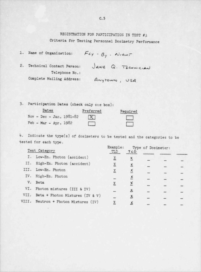
C.5
REGISTRATION FOR PARTICIPATION IN TEST #3
Criteria for Testing Personnel Dosimetry Performance
1. Name of Organization: 8~4 y - 6 A)f s,s e-7
2. Technical' Contact Person: d4o6 Q . T g cu ,v, c.,MTelephone No.:
Ccanplete Mailing Address: A,vy wwm , us4
3 Participation Dates (check only one box):Dates Preferred Required
Nov - Dec - Jan, 1981-82| |
Feb - Mar - Apr, 1982 | | | |
h. Indicate the type (s)'of dosimeters to be tested and the categories to be1
tested for each type.
Example: Type of Dosimeter:; Test Categorv TLD T t_ D
I. Low-En. Photon (accident) X X
| II. High-En. Photon (accident) X X .
III. Low-En. Photon X X_ _ _
IV. High-En. Photon X
V. Beta X f! VI. Photon mixtures (III & IV)
_ E _ _ _
_ _ _
VII. Beta + Photon Mixtures (IV & V)_ f _ _ _
VIII. Neutron + Photon Mixtures (IV) X f _ _ _
.
|
|i
ii
_ _ _ _ _ _ _ _ _ _ _ _ _ . . _ _ __
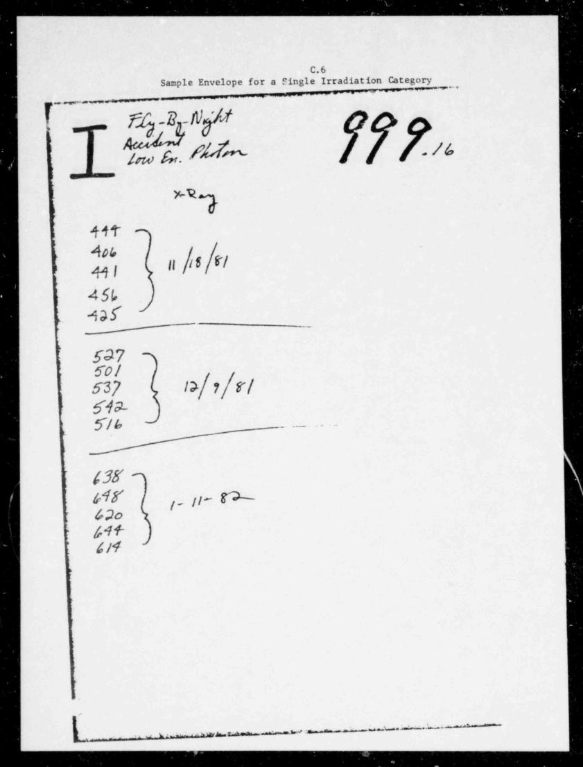
- - - - - _ - __ _ _ _ _ _ _ _ _ _ _ _ . _ . . _
C.6Sample Envelope for a Single Irradiation Categ
_
QMTL 17L_
t C
| f 4t m;
ll 6 |I
.
45f,t
4afs--
.
; S37Sol-
537 l>f 7|V/69-5/6, _ . . _ _ . . . -
,
: asS4r j , . 11- W
'
r 4.do )(,-1f 1-
'4/4'
>>
>
,
4
.
_ _.x_r1 L 1 -- L > - 'A '%MN'N ^ ' ~ ~ '~
-
__ .
_
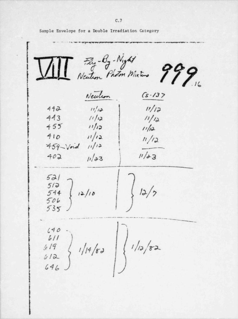
_
C.7 i
Sample Envelope for a Double Irradiation Category.
, ...-.... - . - -- . _ . , - . . .-
[
I k az-|ur fffxs 8 'N
'^
<
u;,
WL Cs-/3 7.
1 449- n/i> 11/1p
| A43 n/ia n/ia; +55 ' '/12 ti/ja.
4'0 d/'a ti//a7 46%v~l ol's i: - .
\40D. 1,/&z l'/a-3>
- = . _ . _ _
GI -
|5/9su ix/a b/7
,
i
ros)> 53 5 i
_. ... .__ _... ._ .._..._._ _ ..-. _ ___.__ _._ _
_
7{$0 -
.
i 6//
6 /T ,|,4|g., |||p,|r1.& / el.
'
fcn > j1
J
, ,
j
_ _ _ _ - _ _ . _ __ - __ _
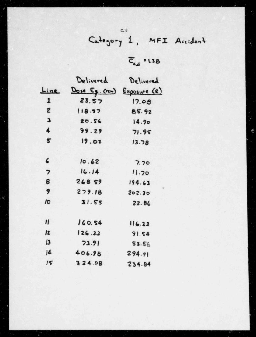
_.
l
C.8
Cahegory i, f% F I Aectjen4-
(j * t.38,
Dehuset1 Dt.hvered1 N o. Dese Es. 0 4 Exoosure (e)
v .
1 2 5. s > J2.oe2 l I 8 17 87 923 ao.E& 14.9o4 99.29 7) 955 l9.01 13.2 8
C 1o,62 7 yo-
2 lb.14 II.yo
8 268.S9 194.63''
9 279.18 2o2.3o/0 3 I . Es 22.86
.
Il )6o.54 ||4,33
12 126.22 9 J.s413 73.9) 52.E614 4.o6 98 294.9|ff 3 2 4.oS 234 84
2
.- _..
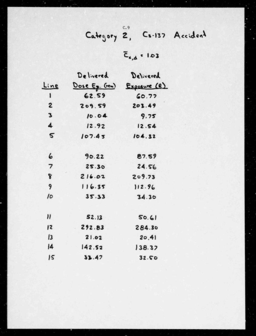
4
C.Ae3.cy 5, C .is? A de*\
(4 = 1 o2
De hvere1 De\weredLine Dese E.. Ge.S Emanauw (21
1 62.59 40.77'
2' 2o9.T9 201.49
3 10 04 9 774 12.9 2 12.5 4 '
S }09.4s IO4.S2
6 90.22 87.597 27.3o 24.76
'
? 2 16.o2. 2o9.739 116.35 112 96/o 37 33 34.3e
Il sz.12 so. LI12 292.83 284.3o13 21.02 2o.41
l4 142.52 138.37JS 31.47 32.co
. _ _ _ _ _ _ _ _ .
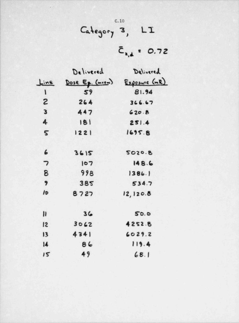
:
.
'
|c.io
Cde3 c7 3, L1
'
C9= o,72
Ds\wered bshsetibest E . (=,e-b Exaowe (w0Mns_
i 1 59 81.94| 2 264 366.67
3 447 62o.8
4 iB1 251.4
E I221 169f.8i|
| 6 16 )r Toto B
7 10 7 14 B.4I B 978 1386.)
9 38T 534.7
lo 8727 12, i 2 o.8
|| 3G Fo. e
12 3062 4252 6
13 .4341 6o29.2
14 86 Ilt.4
15 49 68.1
. _ . _. __ . - . . .
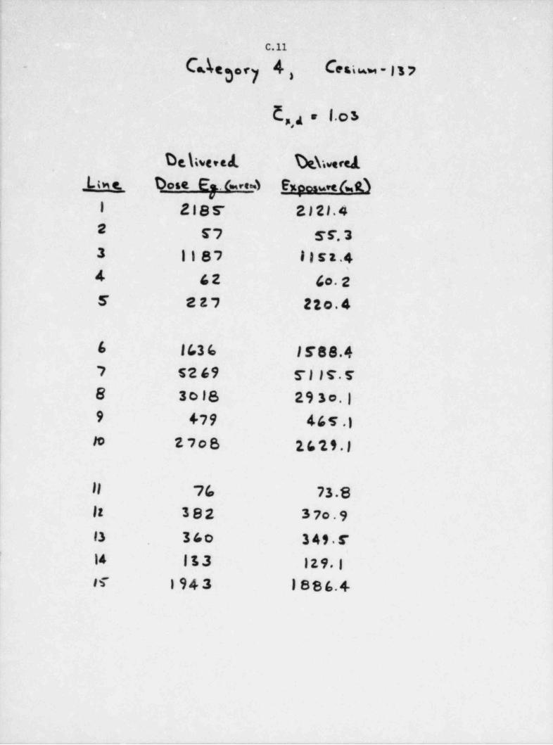
.
.
C.11
- C.Ae3.ry 4, Caia - i s )
E,,4 - 1.o s
De\tvered hbrel_L;w e. Dose E Ave 4 Exoos m & O
I 2 i B s- E l 21.41 2 g7 gr, 3
3 1187 I I s t .44 42 do. 25 227 22o.4
6 1636 l F 88.47 52 69 5I1s.s8 3018 293o.)9 +79 465.)to 27oB 1629.)
i
il 7(, 73.811 382 37o.913 36o 349 514 113 129 1 |
#f 1943 1886.4
___ ._
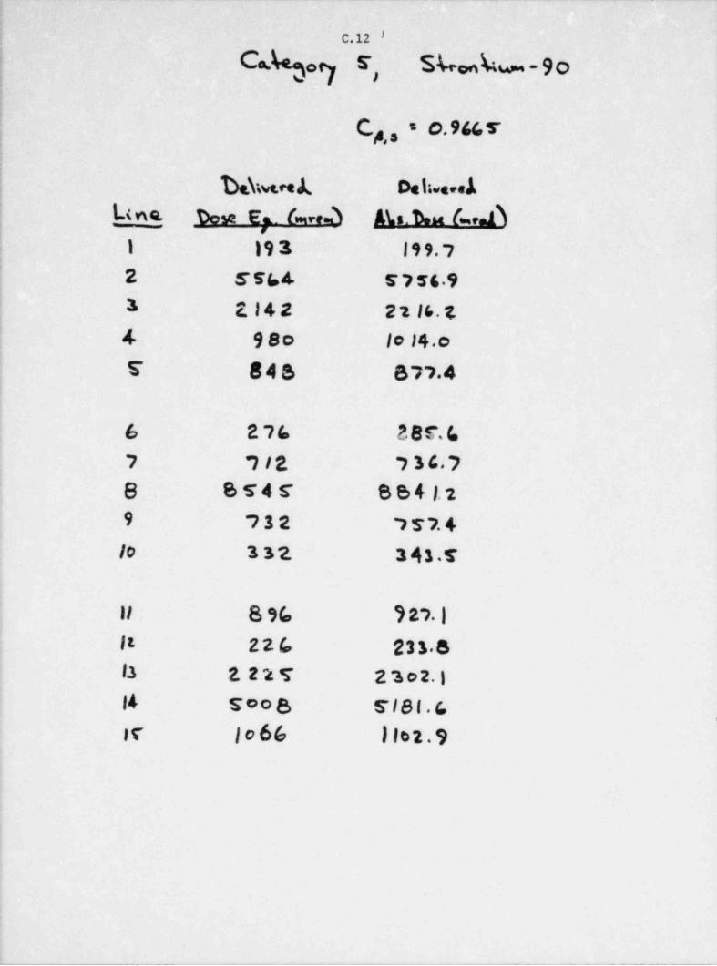
1
|.
;i C.12 I
| Chog r, S 6 6 -9o'
:
.
) C , = o. 966 5g!!
j hb.nA. Dehuni! _Line. % se E =. (= n d Aks. h ( e. A!
! 1 19 3 199.72 5564 s ? 56 93 2.I42 2 2 16. t.4 9so lo14.oE 84S 877.4
6 276 38C.f.7 712 73C78 B T 4 S' B B 4 l. 2,
9 732 7 T 7. 4.
1
lo 332. 3 43.T
11 8 96 9 27.Ilt 226 231.s13 2. 2 2 T 23o2114 Soo B TIBl.G
,
er io66 1l02.9
,
-- ---__ --. - . - - , - - - - - - - - - - - - - - - -
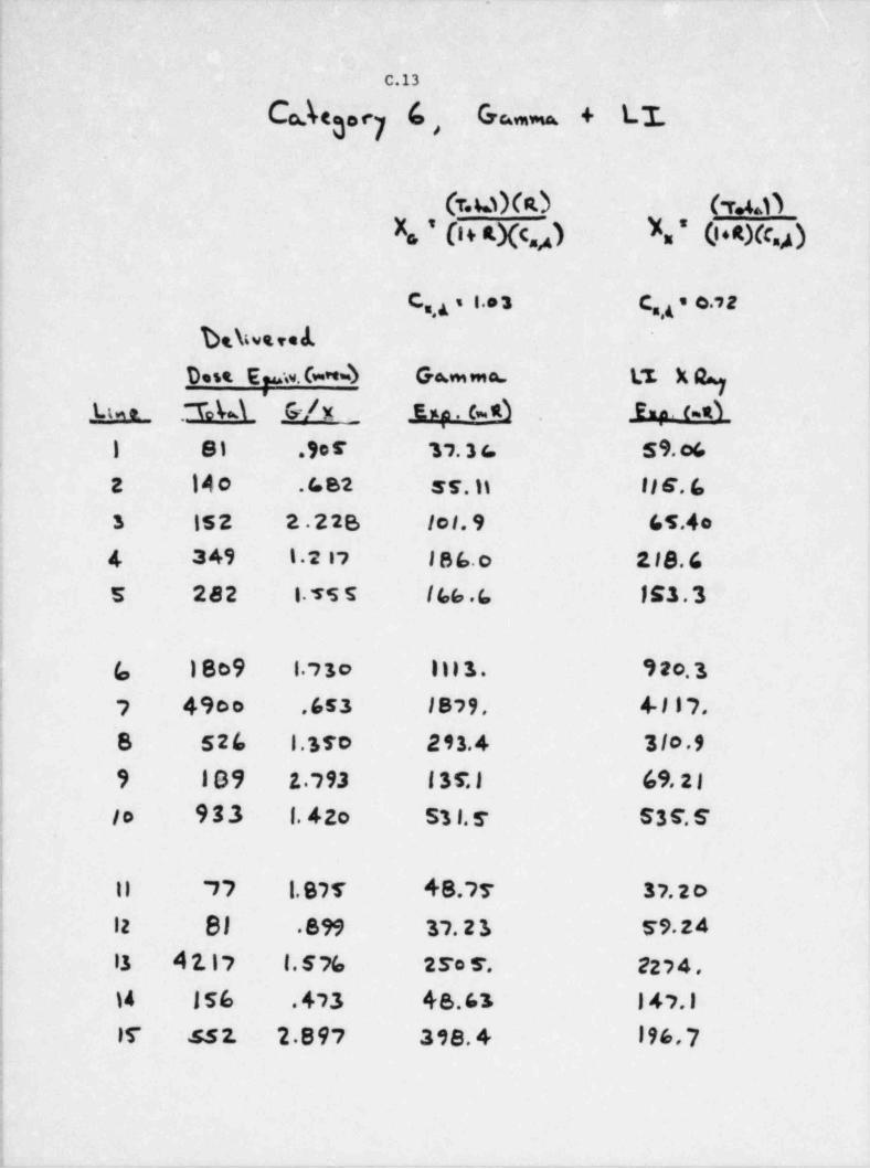
_ ----- . ._ -
.-
4
C.13
Ca.%oc, G, Ga. + L1.
(r. u X 0 heX. ' 04 a.Xc,A N*0+=Xc.4) i
c.,, , i. 3 c ,, . e., z
Dshwseed
Dest E pw.Ga*4 G mma 1;I Xgha . rad G/x _ nu . cA 3 y. c.d-
._
1 81 .9o f 17.3( 59.o6,
z 1Ao . t. s2 ss. n li e. s3 15 2 2.22B 1o1. 9 65.40'
4 349 1.2 17 186.o 118.6s 282 15s5 I66 4 153.3
,
!
| (, 1809 1.73o I n ) 3. 92o.3! 7 49eo .653 1879. 4 117.
'S 526 1.35o 293.4 3/o.9
| 9 109 z.793 i sr.J 69.21
lo 933 f.42o 531.5 S3 C. S,
!
Il "77 1.97T 48.77 37.20l 12 BJ 8 99 37.23 59.241
| 13 4 2.17 f. 576 2ro r. 2274.
| )4 156 .473 48.63 147.1
| If 5 5 2. 2.897 398.4 196,7i
|!
!I
. , _ _ _ . _ , _ - - . .--
..--------- - .- -
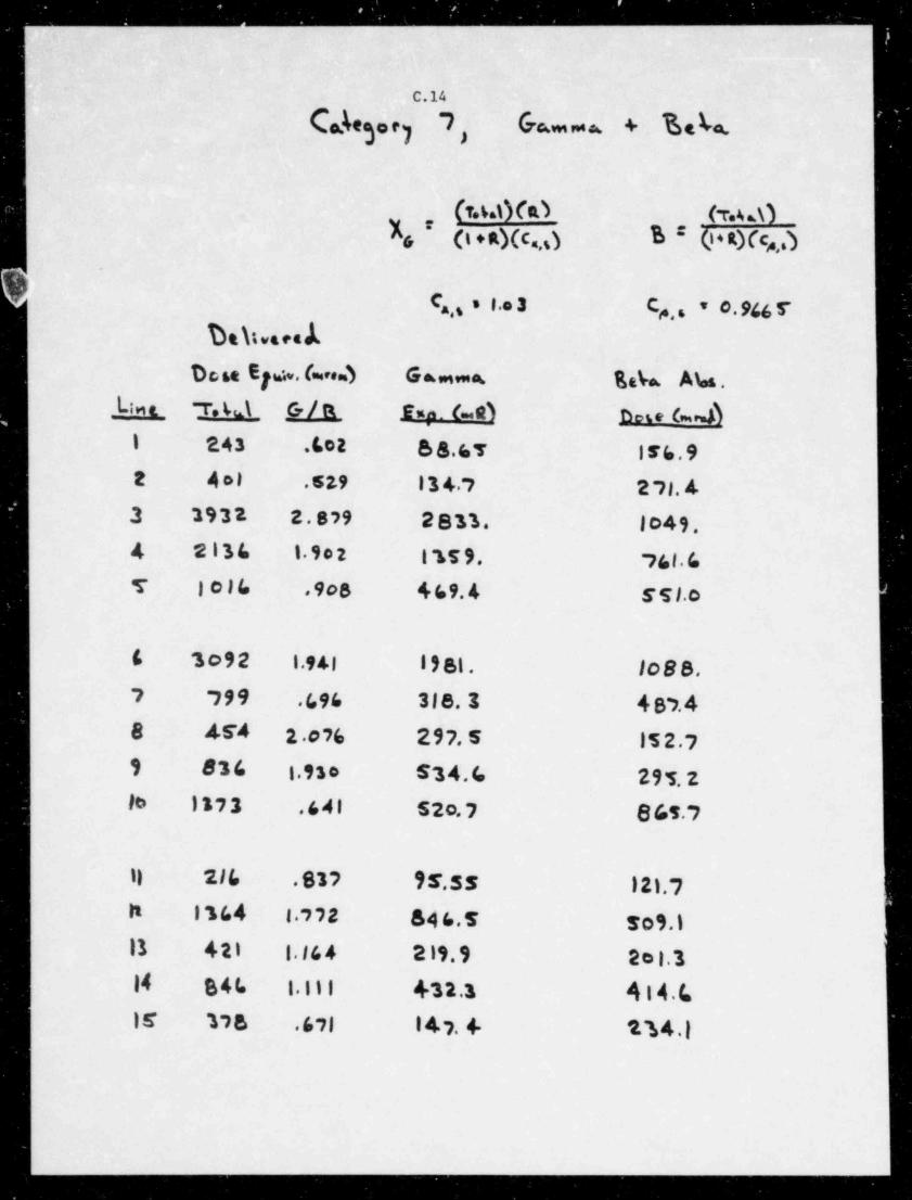
____ _ _ _ - _ - _ _ _ _ _ _ _ _ _ - _ _ - - _ _ - - - - - - - - - - - _
'
C.14
(akegor) 7, ham ma, + De be.
(7.4d)(R) (T.4 OI, (t + R)(c.,5) B (t * s.)(c,,dt
C ,, s i.e 3 C ,. * 0.946 Tg
Dehwacek
D ose Eye .(= .d Gamma Beb. Abs._Lin e r. 4d G/R Exp. 6 R) h e (=M
i 243 .602 6 8.6T 156.92 40) . s 2.9 13 4.7 2 71. 43 2932 2.879 2833. lo49.4 2136 1 902 1159. 16l.6T Iol6 .9os 469.4 5 51.o
6 3o92 1.941 1981. 1o88.7 799 696 318.3 487.48 4 54 2 076 297.S 15 2.79 836 1.930 S34.4 295.2le 1173 .641 52o.7 8 65.7
11 216 .837 95.ss 121.7M 1364 l.772 846.5 sos.)Il 421 1.14 4 219.9 2el.314 B4h 1.111 432.3 414.41E 178 .671 1 4 7. + t'a4.1
-
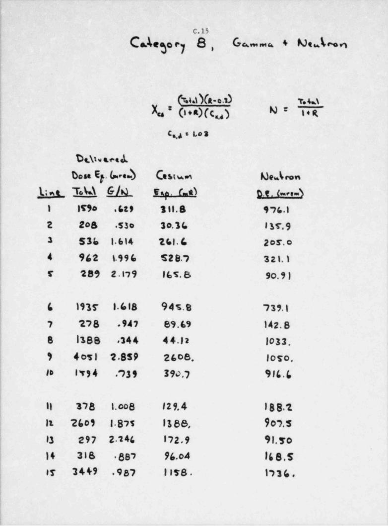
. - . . _ . _ _ _ - _ _ _ _ _ _ _ _ _
!
| C.15
| C deg..7 8, G -u + MeJ~n!
!
(T.44 YA-o.N T. M
X. * C + =Xc ) N* i + R.o
i C.,4 s 1,o 's1
| De.\tve.ce.L
| Dese E . Lee.D Ceuu Me.b np
| La T.k\ G/4 vu. c.e3 n.e. 6 . 41 IT90 .619 t il.S 976.1
2 208 53o 30.34 l 'af. 93 53b 1 614 2 61. 6 2 or. o4 962 1.996 528.; 321.)r 289 2 .17 9 16 5. 8 so.9 )
6 1935 1.618 945.8 739.1
7 278 .947 89.69 142.88 1388 .344 4 4.12 1033
9 4051 2.859 2608 loro,
lo ITS4 .?39 390.7 916.6'
11 378 1.o08 129,4 188 211 2601 1875 1188, 907.5
1
; 13 297 2 246 172,9 91.7 0
| 14 318 887 96.04 16 8 .5
j ir 34&9 .987 1178 1736.:;
:--
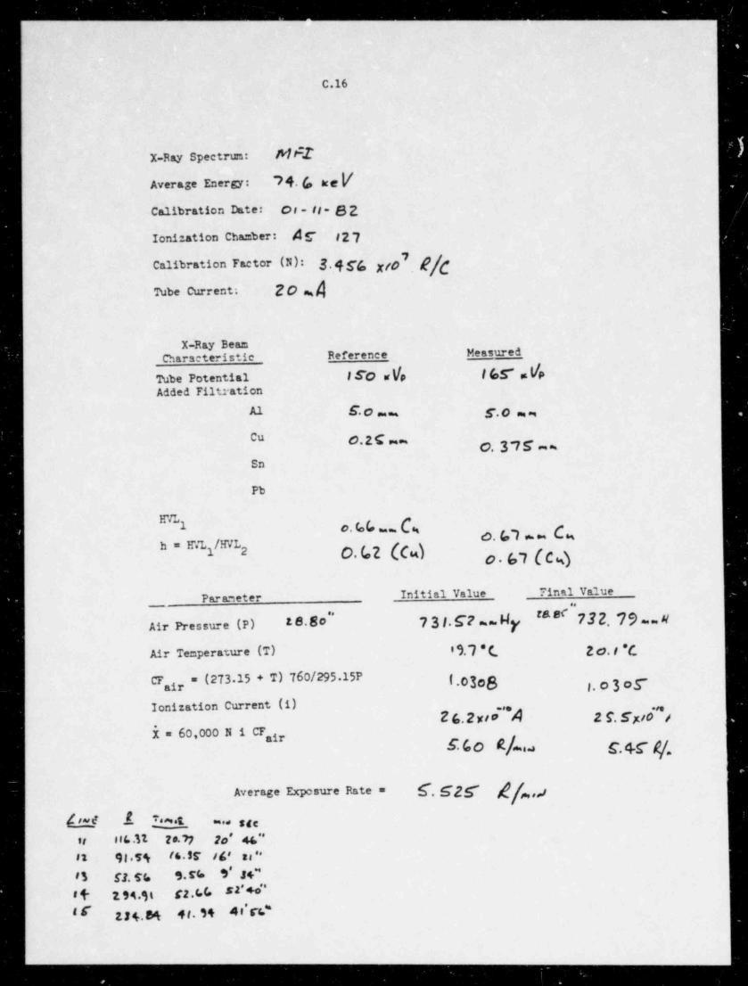
- - - -- -- - _____ _ ___ _ __ _ _ _ _ _ _ _ _ _ _ _ _ _ _
C.16
X-Ray Spectrtn: Mt1
Average Energy: "7 4. (, ac e /
Calibration Date: or - is- gg
Ionization Chamber: /!r #277Calibration Factor (N): 3,4gg pp
Tube Current. 20 M
X-Ray BeamCharseteristic Reference Measured
Tube Potential i 50 w Yp | (o.7 . YpAdded Filtration
S* C ~ ~ S.O m m
Cu C.2 C == gSn
Pb
HVL1 c. bb w. (g O O * " C4
h = E'.7,i/HVL O.GZ (Cw)2foi (C %)O
Initial Value 71nal ValueParaneter
'# 8#"73 2. 79.. #"
Air Pressure (P) 18.80 7 31.C7 ~~ My
Air Temperature (T) 9,7 * ( g ,f.g
Cr = (273 15 + T) 760/295.15P { ,o3eg ,, p 3 o g"air
Ionization Current (i)-'*A 2 9.6K/0 /
*
i = 60,000 N i Unir
g,4 g g g,4f g
Average Exposure Rate = f,ggg ,j
b.!."$ $ & m.* sge
,, sus.n ze.n z, u~12 91 5% (d. . SF / s' ''
83 ff. h S.n 9' .f +"
# (- 94 3L f2.6 C, s2' +o''
gg4,gg 4g, gg 4 'rk"i s'
- _ _ _ _ _ _ _ _ _ _ _ _ _ _ _ ____ _ _ _ _ _ _ _ _ _ _ _ _ _ _
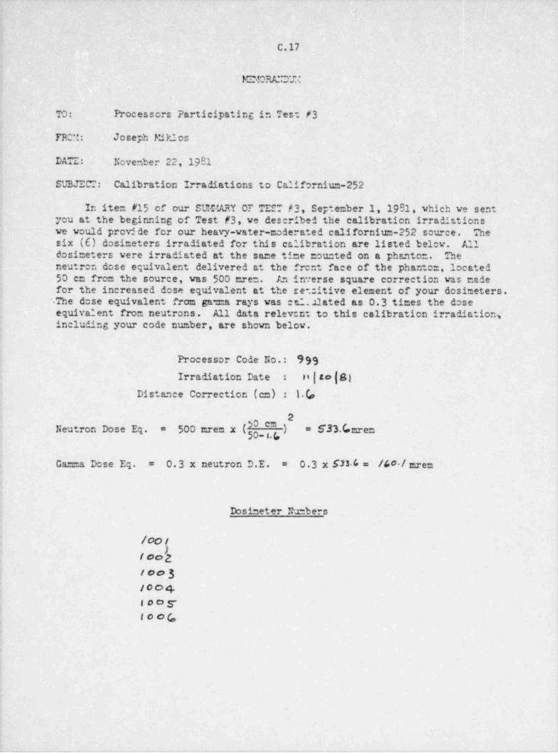
_ _ _ _ _
C.17
E! ORA'!D'U
TO: Processors Participating in Tes: #3
FROM: Joseph Miklos
DATE: November 22, 1981
SUBJECT: Calibration Irradiations to Californium-252
In item #15 of our SUM ARY OF TEST h3, September 1, 1981, which we sent i
you at the beginning of Test #3, we described the calibration irradiationsve vould prov$ de for our heavy-vater-moderated californium-252 source. Thesix (6) dosimeters irradiated for this calibration are listed below. Alldosimeters were irradiated at the same time counted on a phantom. Theneutron dose equivalent delivered at the front face of the phantom, located50 cm from the source, was 500 cres. An in.erse square correction was madefor the increased dose equivalent at the se. itive element of your dosimeters..The dose equivalent from gar.a rays was ed.11ated as 0.3 times the doseequivalent from neutrons. All data relev:n: to this calibration irradiation,including your code number, are shown below.
Processor Code No.: 999
n|to|8)Irradiation Date :
Distance Correction (cm) : 1.(,
2
500 crem x ( _ " ,") = S33.C. mremNeutron Dose Eq. =
0.3 x S33 6 = /40 / mremGam =a Dose Eq. 0.3 x neutron D.E.= =
.
Dosimeter Numbers
/oot
t eo'2: too3
/004I o o ,y
f ooG,
.
_. ___ ____ _ _ _ _
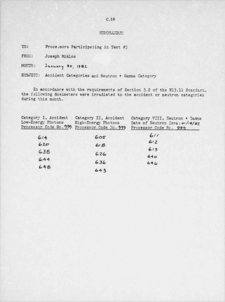
C.18
ISOR/J7&:
TO: Proce asors Participating ir. Test #3
FROM: Joseph Miklos
bws, y 3o,MONTE: it s L
SU3 JECT: Accident Categories and Neutron + Gama Category
In acccrdance with the requirements of Section 3.2 of the K13.11 Standard,the following dosimeters were irradiated to the accident or neutron categcriesduring this :nonth.
Category I, Accident Category II, Accident Category VIII, Neutron + Ga=aLow-Energy Photons High-Energy Photons Date of Neutron Irra: othf/szProcessor Code No.*)99 Proceirsor Code No. 999 Processor Code No. 999
GI4 GOS6/262o 68619G38 626 64o
644 636 s+c648
6+3
i|
I
I
>
___ - - -
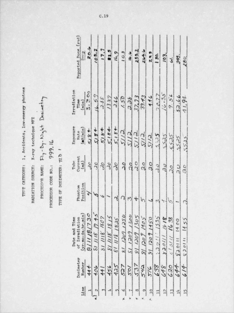
C.19
EE-
h 4"9 5 4 m-
c
=a.m m 4
a t 2 *o. .
* $s u<_AE,e %g o'o .
s o' .4 1o - -~ - 4 g,
bE
|ea.
et
n' s .
' , O M P N b v
8 ^%b- - s - ~ ., s , =. . .
D T.-. " d[ M t M
2 * *ih M; kA 8$ E T 4 4 + 4 4
3 % b b b 4 d d el d % % g 9J 5 .O RST \s .s 2 En s~ ~ - s ~s s s n n~
39 W W M M h Q Q Q Q Q M h M.,'8 8 9 5'
1; -t. <: v. eo h i 6 -
$ V- W p Y,J A 6. @ 4b
ggggg .q! Ej,c ,o g n a m n ns o e c 0 o o 2
,2 3 oa. n n e
|.g = , 9
e8= -
h"$ g8o 5 99 Ch s a
|5u. ot
sv} %o os s
e a-le ce i O n + b e m s- \n d= c -
=.u
k$ N 4 s O
! 5]i t e: 4 e e 2 4 :t : 0 te z"
sii h % t t t x *t
s s.Do N D D- N N % Cet rbs s s
jH E % % N N D N k Q Q 'n *g Nsouo N D o Os
[ b Sc N h k N*
h h3
'.
I h 4 % 4 \
% h q n O O QK M t 4 Ng e n
T T M b b G %% % % wj= v v
I - a m .:: e w t- e o - N mg O $"7 x > w v. (l
|
- _ - . - _ - - _ _ _ - - -
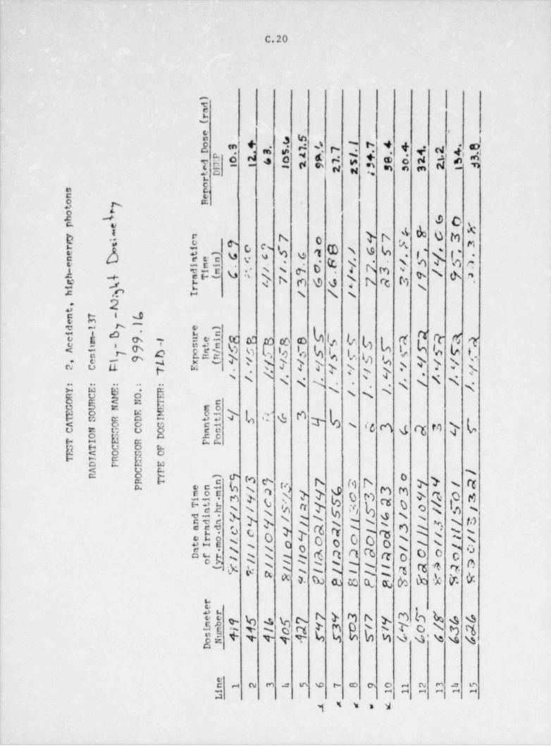
c.20
;E-
'E a s ;
| 2 9 t ; s d 'l r- 7 '' * + v w4ei.
N. 'E S * b d k N*
1 t'E t<
1 3 n m .
1 O L
| t "o @ O s
f b D M f'b s C N o } b. es
$ !E3 M ". 9 1
()< N Y E 4x-
h m ''' e Dd %. es .4.A *;:,5 s3 :J q<
-
# b n \9 0 b rt, MS < t--
sc e - % % s,
a 2' 35 #;
e - s- . -
b l i.e.Q3$TEr $3{ 4 rr (6 q'tE o': e e
L,Rl b b la i.
e,i; r* 2.s1 D % 'o b h
p >b< l.eE*c a-t t t > > >
ete
'4 (>> > sJ >>' N 4 S S.N s' s- s- q. . ... .. .. .. . %,
W 5 Ng5b *d
%N s5 G sEo
IS 8 E E 3 :: > l ,r g n Le o # N ' cc 6 g et to } L5 8 8 g E i;=2 8 i: 2e c:
g4 8 bE E OwE 8 "D
s0
SS"[n$ C d >rr.c3 M o M b d '> s. rt
>N@gg v
$ M d Q l> 0 m o e
r$ ( b o s a sS t .h s s. %ha > > >s $ NN R N s s s tas s.-
O 's si>c?c6 rr,
'0" E '? O c ' s~ mo -NO o o o s s34:8 s
N #>'sR 2. '6 rt et cb er 3 0 0sus D 'rs s
i.k $ g' R 2 R rs r6 4' 0'
* 0- N o te t% h th k r,1 ks .
.
t
MhTj d c, bN > M N E o Q.5 e. , %, 4g s
g g q > m a s s s. g gb M Q Q ' \t sa gjE Y T T T T k k A
- a m = m e e- e m 3 g g ga m
,4 s , 2
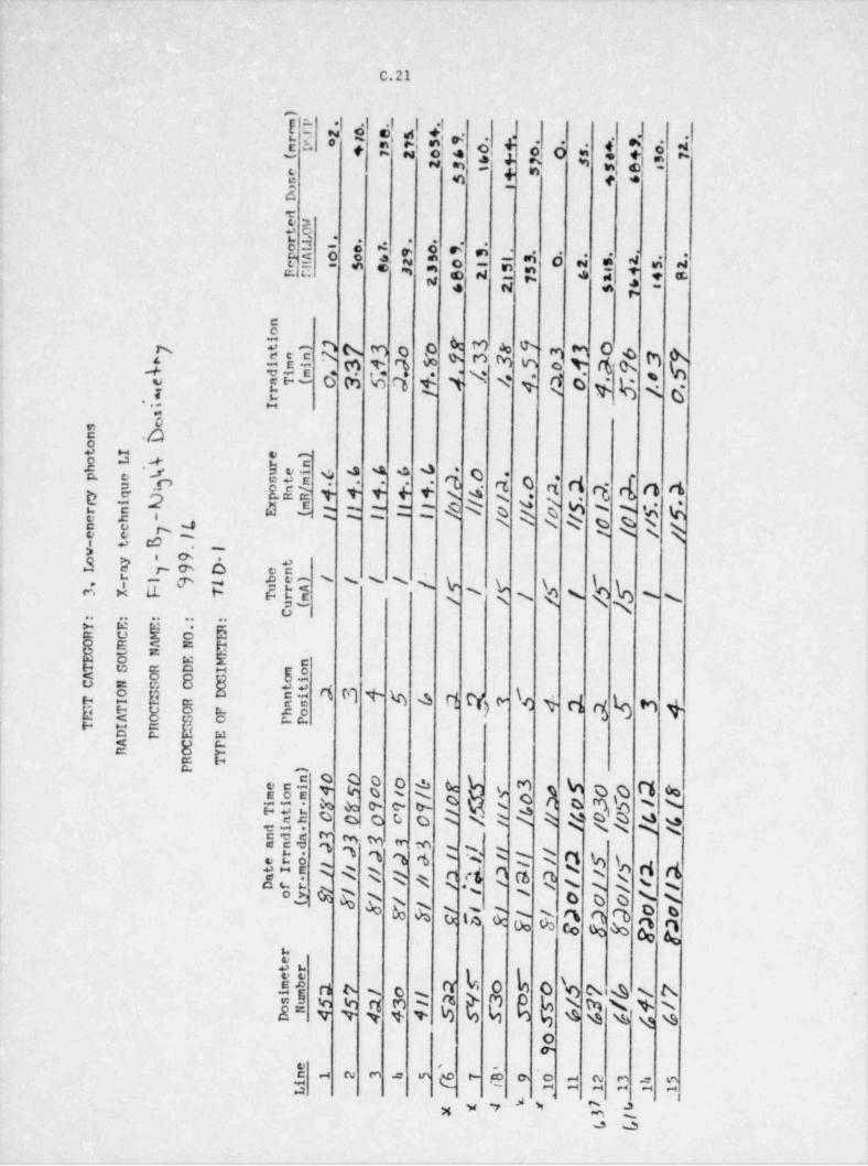
C.21
h +Yj J * 1 ; $ o :i f g ? *le: . =
. . .
0"
c
I E
U$ b *ik *$$$ " =1 6 A4"A di15 -
gE *d!* * ed *
C
.A c7-c- n + 3 4-t p:3 6 c6 M ct ( U. N' i Go. i M s- 6
n. i. u
-;0
E ./C)3 m e -j, 0 $35 9 '*. ''
"i ''b D. d O d d q r{ 0 4
)ff !$ $-
N k N k N i k ( f'w t '
e, e w~.a> i o . o
km x u. s N \ % \ogs s N g s s'.. .. .. .. ..
b $o|s =gs.!8 8s -
ea: k,8 u n n ~ n en m a w %et b fee sE D wn 8 "
Cm"e o c o o c w m k o d %ggg v v s s s h o rnt oe% & 0- c- 5 o s s.---
* % .h.tso o o U o % Nk % Ns %y' a% o o.e . s s
g N. t: 6 2
% % % %' %% 4 ', w' t s Q D h d d5-s ss = % c ;'4 c'm a ds. s"tkQ g s'5s D D 0
g)b N A D tl EG; & Q QQ Q~
.
0 b]! 0 h $ h s' @W% C E @
O A4N A.~
%%D D$Ov
I 4 W M 4 m M.
O O [ h C $ $g''
,,,'8 %ta o
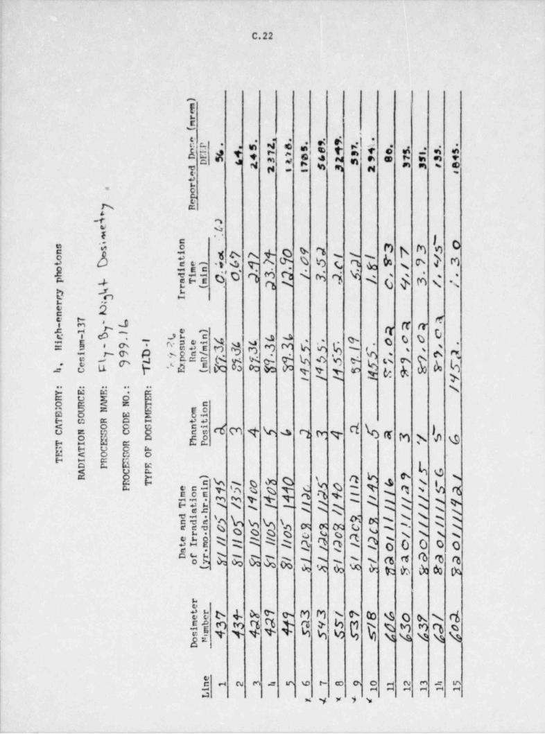
-
C.22
-
E-
di 2 +<I ame ,a u ,u m . * w. m +* m ,. sm n* m m ~ *r
3 e .
I'
E
p A|
-r , ie sE
I$ 4 4 M b M Q 9E 5 go s + k.S d s s M o 4 M% b c qaee- , s:, v
<%s
1. jfj 6 0' i $ Q < M i Vc' $ d s' ;#
b 'n b*
E, obd q oN N. -
c o ue . o n. .
nh 7'
g''
.am m s. vs e. -
g u .n y > g,, - a_/ au * y- 'd 5 cc po s -
<p<& 3 (3oc w y v ev.s *- >s -
Q & *: i %** '
E da 2' =E a 8.s
c
m.e a m ~ es
$ - T k % %' Qe no sm "
h5 e '2u- g~
fE $$ c o ' O h b %g g ;; w-G % *g a s
.y t t T q s e r6t v cS s,
[sPgj Q Q R 1 1 3 s R D D R R,'s
s
~\--. , ~ ~
a$~
5l. g o o o a c o n\ N%.A @ M CK: ( %
{AR R :: ::: =cu s s s s
0 B o o o o::: aQ 0 s
a t .4 5; g s; s; g s s cs n (b ro res s ~
A w h * & w b & 4 >-
btt 6 4 A d o M M N b to 4o S. s. cf% g h h M Q g %M o q oG e hgSj m m
TT 't N % % N3 \sjc
| j - a n o m e r e m o a m =n n" ~g y > s
|
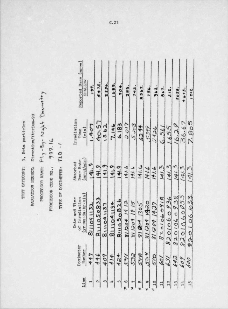
'
S"
)_
_
mrm.(
en Wo O . . . ,
z 6D L . s . . .
e +_.
s z 7 ,.L 1 1 s . . . . .4 z 7 s a t
y s,n
ys o. d A 9 o 8 e. 6 5l + 2y e i # o 5
s o u
- t S s 2 2 2 s 2 2 eb z +ssr a so' p.
~ eR
's-e
D09
- n. s m 4 o 7 7 S3 ? 3 f f L S 9-- e u y 7 5 %8
i 1 /l i 6 ot ) - l o 1 1 4c r aen o bO 5 S 1 Ro. JM
.. i t 1i mi
a T (m 4 0 1
.- t t 3 64 7 6 Q 5 c "T
. .di .5 .r Y f2 (,. 6 3 7a /p m - L r i1r l. /
,
u 7 I I I6a i- . -t te n - 9D o y9 Dr. t l 9 l )
5 S F T endti. eam 9bR/ 9 9 9 9 6 L L $ 4 3 3 3 3 3: : : : :
. .Y E E . R r l . . . .R C M O E oeru \ 1-
1 1 / /. |. / 1 1 /-1
4 4 4 4 4 4 4 4 f +1 4 4 4 4 H1 .
l- O R A N T ssrC U N E bo- E O E M A D (m t 1 1 1 1 I I 1 | i I 1 1 (T S R D I
A O O GC N S C OO mR Dr I.
. u, T C O F )- -r A O S O nT I R S eni 3 A 6 83 3D P E E mom b -
33 5 33 9 S f 0 7- /A C P ii - -R O Y Tt r 2 7 4 .
1 I 9 1 9 9 o2 2 9R T a h. 3 B 3 5 o84 t 34 M o o 0e lP di to tnd n i tt 1 I
ero 4 - A 4 o_a a d. Si l 1 6 66ro 4 4 + o b G 0tI m e o o S 4 1
o 0 0 p 0 0 o O 6a i- i i1 sDf r 1 t i 2 9 # |) ? o 1I1
m- oy I I1 11 t s 1 /
|t / 1 o o O o( I8 R B 8 8g f V [f 8 & 2% 2%l
/*_
3 3 9 9ret ree
9 + + / 7 sY o // 2 f 0mb 7
M fim 4 yD30 a v 0 3'su /
s 4 4 H_44 4 4 d 5 S o 0oN sD l 6.
.
- en 1 2 3 5 6 7 a 9 0 1 2 3
a ssl
1 1 1 1 1 L1iL -%* < *<-
.
|I 1| ) l .
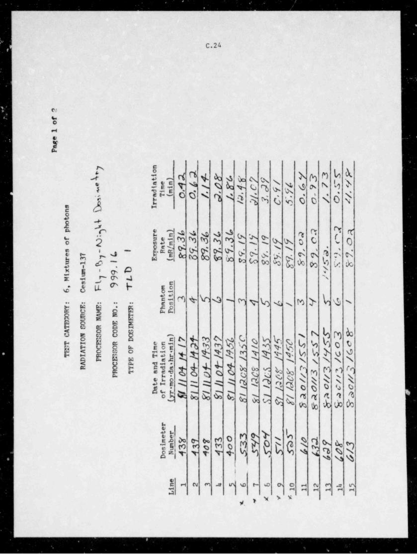
i|| ) )l 1j\ ||| || ||l
_
_ c, N
2
fo1
egaP
y ny 3 3 ~5 P
ob 2. 3i - r4 E 6 8' 7 9 |t )
4 & 9 7 2 '/e aen -fcA / D 8 4 0 2 V 9i mi~ di m . . .nT( O 0 / 2 L 9 /
. .
r 1 2 3 C' S. o o / 0 4, - .i
br e
s Inoto 4h (
6 6 6 6 6 a 2 2 ap ) e )r n 9 V 9:uei 3 3 3 3 3 ? 9 >c of
Oo o st m 1 I 1 <t .on/ 9 9 9, | / .
C, 9 ) a ),9 , , .s -. .pRRI
9 9 9 Y. 7 '^ 'S
.e 7 C x m W 5 8 '/8' 5 $. 8 S V 9 8r 3 y 'E ( - cu 1 bI T. Et - . D /x m - 9 'i u l-M i 7 9 l
s t n3 T mo, e F6 C oitt ~
ni 3 4 6 b ~
3 f s &3 4 5 b /I /as: : : : :
'-Y E E . R h oR C M O E PP0 R A N T
U N EwO E Mt S R D I
5 3 8'A O O S 7C N S C O ) /O S D ny t 3 7 b 0 0 5 T. 0 C C 5 o cr I E R eni a 3 3 5 s / 3 4 5lT C O F momwA 3 4 4 I' 4 5 s9 c GH M f 4 MO S O ii i *T I R 3 Tt r I / / I / lD P E E a h. - 1 / / / / /A C P di - -R O T nd n + 4 f 4 4- W S s. f r3 3 3 3 3R '1 a a d. 0 0 0 0 0 c C c O o / / / r /
r / / i /P? )ero | | ?
l) | 'c I ?c d /I |tI m | I |/ / o 0 c c c- | Ia
Df r l l IT W ?) I
I I 1 / a A A 0 aoy E f F 8 R 9 f fl!
E & S W( -
& r
re
mb V 9 7 3 0 3 9 ''t' 7t ree
V o / b /o 1 9 7 3,/
3i m 3 1 0 3 0S 5' fT s f, 3 9 0 /su
oN 4 4 4 4 4 (D 4 4 6
_en 1 e 3 h 5 6 7 6 9 o 1 2 3 h 5i 1 1 1 1 1 1L
<-*. * * V __
__
' .|||
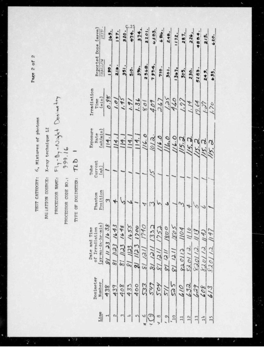
|l
.h....,-)
k, s.n P s . .s
,+ n+ ne E e e <. 8 z1 6 s o.
. . .r o 4 .r E oc a 1 a 4 ,_ s2 sm D + izsn s 2( s s a 2 e z soe <e
soD
2 de Wf t Oo . .r L . . . e4. .o L o ss . , . .
..2 p a e, s ss o r . .A t ys e s s sg RSi
ve l
s. as vss
,s eue e 3 ess s n s 4 sa a ' 2 2 2 ee
P s_noi
'8 /f / 6 I 1 L
4 97 it )g 0 7aen 9
o.4 7 3 0 0 l, D f 4 7 oi mi4/ 'tdi
a T (m o / l 1 1 J. 7e '8 4 D /. 4 /.. . .
m rM,
./ / /.r;
3 I
%snoto Ih L 4 e )
r np ( uei I 1 I I Ie ohc 0 O 0 2 a R 1c
st mf u oa/. . . . .
a pRR 4 4 4 A 4 6 / 6o q . 2. .
i
||/ni cx m l 1 1 I I 65 f S. f. T
s n t // G /E ( I 1 i I / /=e h - fc I
/ / / / / / / /r c !
/ / / /u e I
t t .xi y - 9 D tq )9M a nl ee)r6 X F T bra I | l
, -
SurT u (m / I ( i
C / I / I / / / /: : : : :Y E E R.
R C M O EG R A N TO U N EE O E M nT S R D I moA O O S oiC N S C O ttO S D ni 3 + ^& ~4iT I E R as ~4 3 5 o I 3 f 5 4 /
lS T C O F hoE A O S O PPT I R SL P E EA C PR O Y
R T_ P )_ n 8 3 8 S o 0 3 2 0 f 4 0eni 3 4 4 S o 4 3 s )T 2 0 1
7G Om o m. 71ii b 4 4 s ? 7_
.
_
Tt r 3 '? R 2 1 /__ l / 1 / 1 /
di / l / / I / // / ||_
a h. /_
nd n 3_
a a d. > 3 3 3 3 l / L 2 A1_ r 9 D 2 ? l / l / 3 6 oIerotI m || || I 1 /
l / I. i / / / /I 1
a/3
/a dJ fa - / / l / /1.
Df r / I I o o o v 0_
2 8 8 F E g T 7 7 V p A G_
oy 1 1 l.
_
l / l / / / 1 2_ (
c_.
T T P. 2-.
__
re
- ee 8' 9 8' 3 o 3 '7 '9 T a_t r -
M/ O f 33 ~9 0 / 3 / 3mb
im 3 3 0 3 oT O /$ 5 T 5 f, 4
suoN A 4 4 4 4 't ( 4rD
e
(i)n 1 2 3 h s 6 e 9 0 1 2 3 h 5i 1 1 1 1 1 1L '
g1 a '
-
7 | || |||
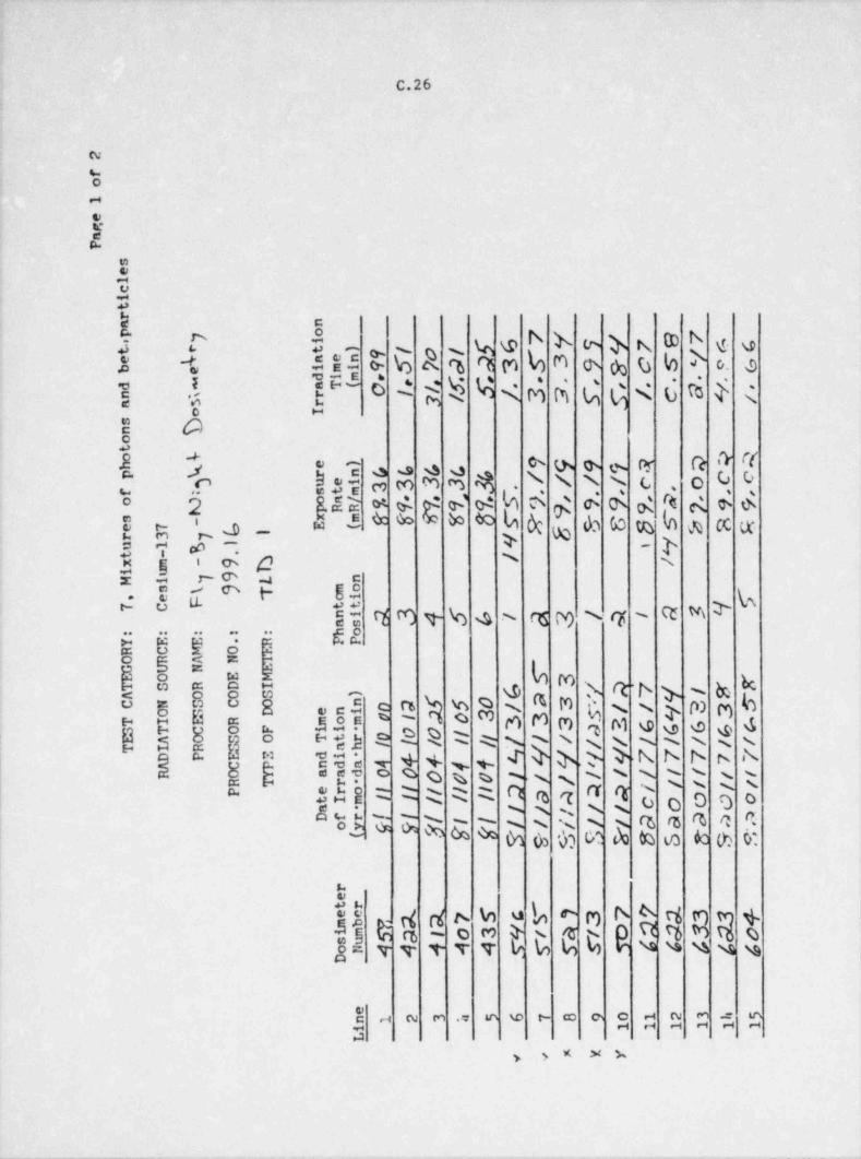
C.26
N
O
-
W
e:0%
h $ b 'h > 4 N W h.n g e 4 ot J 3 :3 t Qi R 4 q n k m o h G b D o. 4
{ .'} P3 $ 2 M M k $ N G Q < d S f'
O M
$ hj o m e ts e R * T+ , -
4 334 3 M 4 4 4 ' x N T ca9 9 4 |
. -
t e e g s s W N.
5, J - pa e s s ea+ i
s ew e L A c e m bs e e. a x,em 4
* *- y3 T #~ -
. s
T $ [p 85
I @ sK gE %5 0 * b
j{ q m t % 4 s G "M MNG '
ge.. .. .. - ..
e5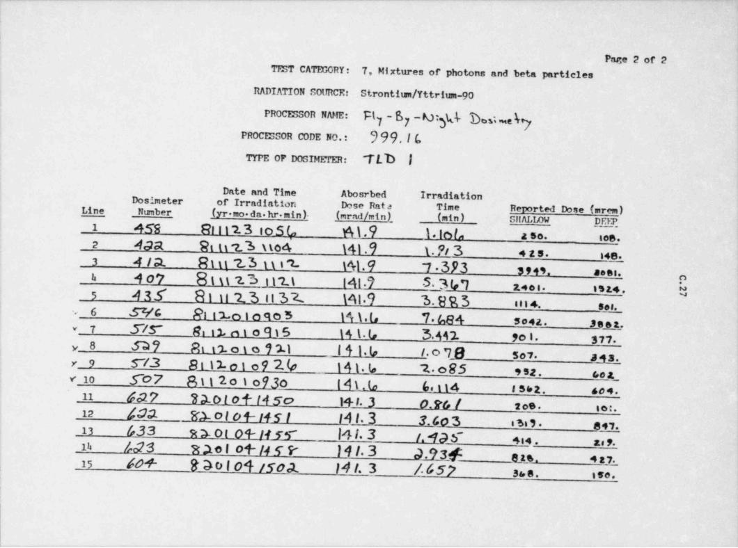
_ _ . _ . . _ . . _ . . _ . _ _ , _ . _ _ _ . _ . _ _ _ . _ . _ . _ _ . _ - _ _ _ _ _ _ _ _ _ _ . _ . _ . . . _ _ _ ._ _ __
i Page 2 of 2TEST CATEGORY: 7, Mixtures of photons and beta particles
RADIATION SolmCE: Strontitan/ Yttrium-90
PROCESSOR NAME: Fly-6 - Dt)d- h Ne7
PROCESSOR CODE NO.: 399,I(,
TrPE oP DoSIMerER: 'TED |,
Date and Time Abosrbed IrradiationDosimeter of Irradiation Dose Rata Time Reported Dose (arem)Line -Number (yr mo.da.hr. min)- _(rirnd/ min), (min) SIIALLOW DEEP,
i
1 4 59 81 i t ?_3 s o S L, M.9 1. lo t, a so. ies.
*
2 4da 9t tt z.3 no4 141.9 L Fi 3 4 as. i4e.
,
3 4 /at. R 1 i1 '2 3 a i'2- 141.9 7 393 3,45 a.. .b 407 81 u 'z.3 i l'2 \ 141.7 S.3 VI
na4 e i . ist4. h5 436 81 1i '2.3 ii 32 Mt.9 3. 8 R 3 m 4. so,.
! 6 Sr/G Ri Lo i o go 5 14\.L 7 684 so4a. se a t,
.-
i 3/5* Rn i1. n 1 o 915 \ A \. lo 3AA2. 90 |- $11.v
y_ 8 S37 At t'2. o 1 e i ll I 4 1. (, I. o 7E sov.3 4 a_.y 9 S /.3 Bi11o1o9 % 141.I, ~2.. o BS esa. t,e a_
-
! v' 10 507 811'2.o ) 0930 14 blo 6, t 14 iS62. 4o4._ 11 4d27 23.O l o f (4 So 14 1 3 0.9T, / 2os. to:.
_
| 12 400. 82. 0 I o 4- 14 S I IAl.3 3.49 3 ssss. e 4,.| 13 /,33 R s o t 04- 14 w I41.3 /. 43 S' +i4 . a. 9.Ib /,d?S 3 2e1 04-/4 S P )41.3 a.?sg o .. 4:115 40+ Do i 04 /50et 14 I. 3 /.657 see. ise.
_ _ _ _ - _ _ _ _
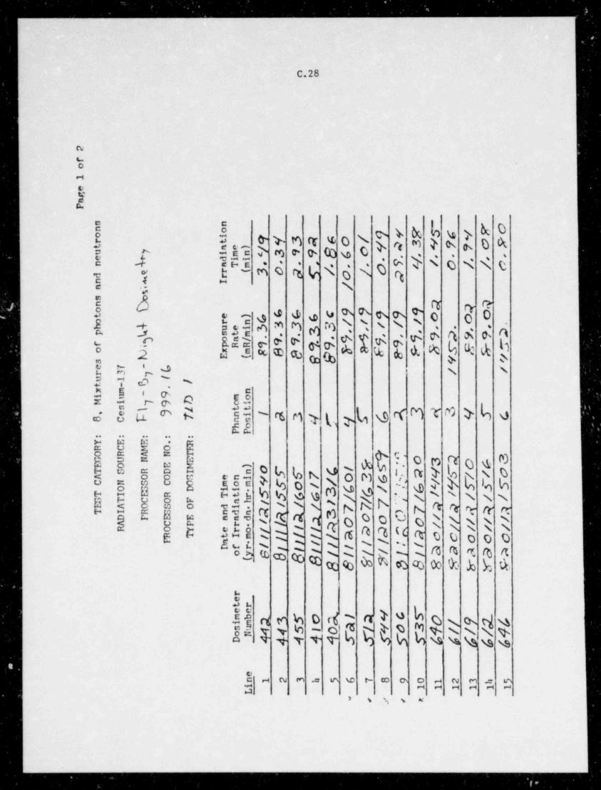
I | |I
aY
2
f-o
1
egaP
Ws n 7 Cn o } Y 7 G /o ir t 9 l' 3 R g 0 / '< '
7 9 0 P3 9 9 8 6 0 9 A 3t ae)
/'.u y i mn
/.. - .e " dii -
. . - T t / O /, /, 0.n k aTm . -
O / 03 0 B K /.t r (
2d rn A I /a
's.
b 2, Q Qsno 6 G 6 c 9 ? 9 9 9-
0 0 0t e )
% / ' / | 1o r n 3 3 3 3h k uei - . . ,,
D. .p h st m -
9 9 9 D 9 ?M
, *
r pRR 9 9 9 9.oa/ ,
E U P Fr S' ? r9 9 ri
o T Fx m F 8 8M E (s 9 9 <
'/ '/e 7 - 6 / lr 3 7 /u 1t - 6 /
.x m n- 9i u O moM i oi9
[ G 5 3 d 3 4 T Cs 2 tt
, e 9 7 ni / 3 3 4 7 ]<8 C ash oPP
: : : : :
Y E ER C M O m
.
G U N ;
5-QO R A N T ? 3'. o 3 2 O Gt 'E O E M )
%~7 5 ST S R D I n o F *S 7 C l
/ o 3 G 5 a /' / / 0A O O S eni v 5 O / 6 '/C N S C O m o m. !
S S G G 3 C G, /O S D iiT I E R Tt r l // / ? / / / /S T C O F ah / 1E A O S O di I / / 7 7 7 7 2 2 R R 3.
R a A LT I R 3 0 0 O / / / / /D 'P E E and
nd n
R O O / / / / // l .
;A C P r. / /R T tI m / l / / a D 2 E R c C 0 C O
R O Y ero / |P a |
/ /- l / / | I /Df r // | / / & 3 3 B A1 i Ioy 6 8 B B
| /
8 8 9 7(
0 8 8' 9, b Y 9'--_
ret ree ~a /' O 5 0 / 9 7- b23 5 o s.mb lim
0 ~a L /e O 3 4 / / l $o
oN 4 4 5su I
D 4 4 4 44 S 3p S 5b$$ b b
en 1 2 3 h 5 G 7 a 9 0 1 2 3 h 5i 1 1 1 1 1 1L
- < ' n-
| 11 l } | ,|| |1|| |
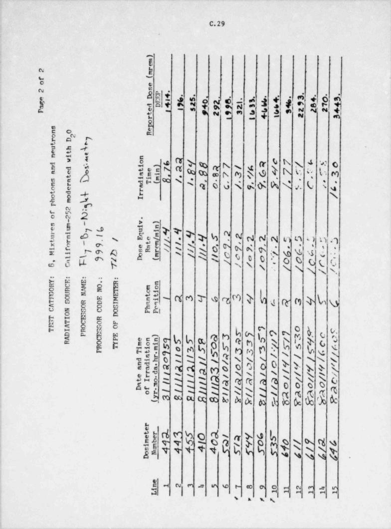
C.29'
|
^
E |
k |a'-%
C D
j g4a
&j w' e 3, $ei* 4 4 6.4. .
. . . - - -e e - 4 m .
+on e.,W ak e e e- +.c o+ e* 4
, 4 $ g u vw+m 0 ~~ *N M O= ,
N 80_ -
EE o sE o" mo s
.z .c e.8 -
e a]h' h:3
g 4 h x 4 w o$ N $ $G h" %2 'l
s|u$g i o gi:3 * s, -: q 6 g < g o: h % b.
e 0 bt
8 ..4- A \'o.c e" .Cm
!. % C2 -i > -
!E ^d li ,T T >d g 9 N NN N id n t) nnI $$ 6' $h k 's $4 o' S $ 4 6 ;( Q d si' d .:"J*GE 'R 3 N R R $ b o O e o t e t G: g g p. p S \ N N- N N s, s.
,.
,
$b Eg g h *E E
S9 SE - ct s .r % m d e g e n h
!
4 " 8 8 G E"['" 8 8E E h" ! bi
" O k v-( o n" 5E $2 o c 'c e b eq h bq 'g p' ] 4 g|en }n g! * 8 h 337 % % P h Uto rq Oo: S et- e a - v:, s'864 0 s t N s N- s: s s s s s. s~ ~ ' N
~~52 4 MD o o o O b b k d 'si s
" E .5 7 s s s N 's h q g'BAe t Wm m rc a m
s sz ~N o o s oe ni m s s s s s s s 4i od % % % % s % N N % 5N %,2, M m R @ to k A ch M d: b b ,
g
u
h D N 4v, +W +- %s
% ASj e M @OQ g g Q uq
1 s.+ >p v s., s s s s .
j - a m e m e r e e S c g sa ea
s ,(s
,
n --
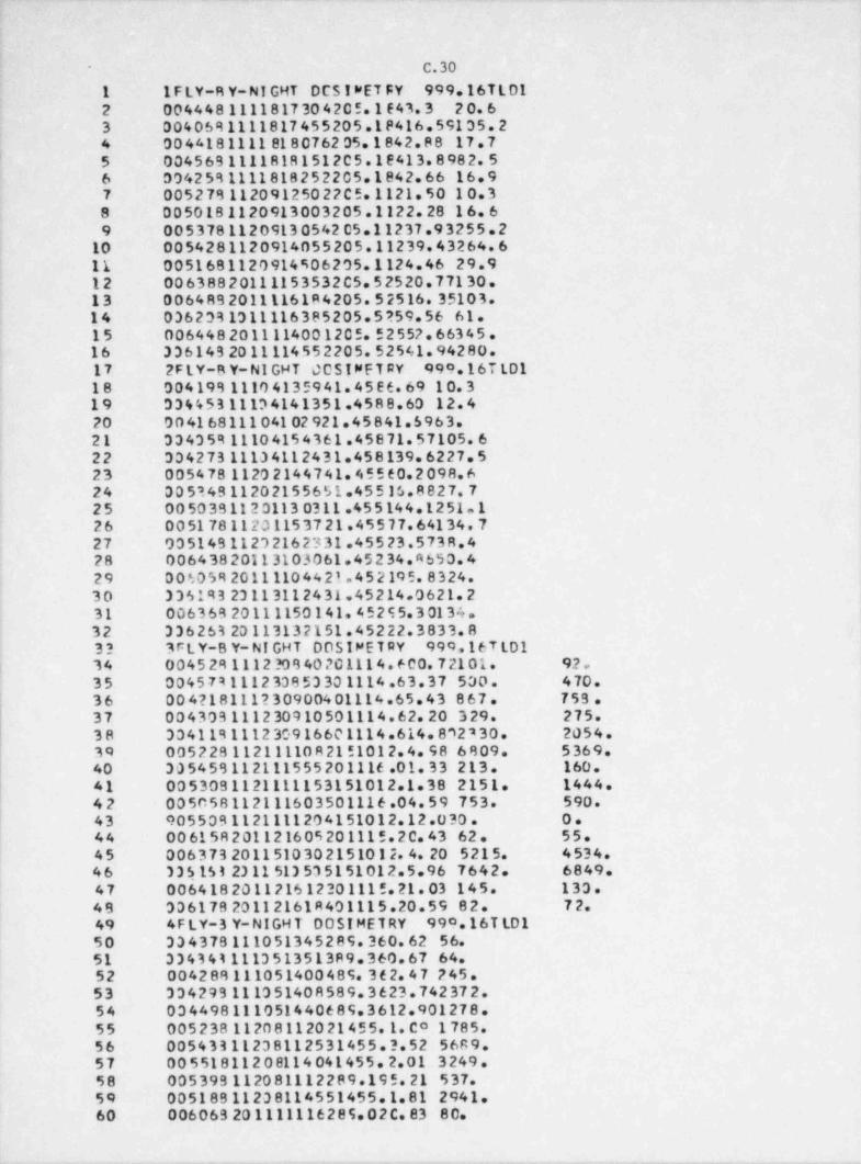
. . _ . . - _ .
- C030
1 I F LY-R Y-NI GHT DCSIWETFY 999.16TLO12 004448 1111817304205.1643.3 20.63 0040691111817 455 205.1 P416. 59135. 24 0044181111 818076205.1842.88 17.75 0045691111818151205.18413.8982.56 0042591111818252205.1842.66 16.97 005279112091250 22 C 5.1121. 50 10. 38 0050181120913003205.1122.28 16.6,
9 0053781120913054205.11237.93255.210 0054281120914055205.11239.43264.611 0051681120914906205.1124.46 29.912 00 6388 20111153532 C5. 5 2520. 77130.13 0064892011116184205.52516.35103.14 0362331311116385205.5?59.56 61.15 0064482011114001205.52557.66345.16 336149 2011114552205.52541.94280.17 2 FLY-B Y-NI GHT 00SINFT RY 999.167tD118 0041991110 41359 41. 45 E 6. 69 10. 319 33445311134141351.4588.60 12.420 00416811104102921.45841.5963.21 334359 11104154361.45871.57105.622 334273 11104112431.458139.6227.523 005478 11202144741.45560.2098.6'
24 005349112021556S1.45515.8827.7-
| 25 00 50 3B 112 3113 0311.45 5144.1251.126 00517811201153721.45577.64134.7
i 27 93514911232162331.45523.5738.428 006438 20113103061.45 2 34. A 650. 429 00605920111104421.452195.8324.30 336193 23113112431.45214.0621.2 ,
; 31 00636920111150141.45255.30134. -
32 336263 20113132151.45222.3833.833 3 FLY-B Y-NI GHT DOSIMET RY 999 16TLD1
( 34 0045 291112 ?09 40 ?C 1114. 600. 7 2101. 92.35 004579111233853301114.63.37 500. 470.
'
36 004?l8111?30900401114.65.43 867. 759 .37 004303111230910501114.62.20 329. 275.38 334119111230916601114.614.892230. 2054.39 005 2 2811211110 R 2151012. 4. 98 6 809. 5369.40 305459112111555201116.01.33 213. 160.41 0053081121111153151012.1.38 2151. 1444.42 005058112111603501116.04.59 753. 590.
| 43 9055091121111204151012.12.030. O.44 00 615R 201121605 201115.2 0. 43 62. 55.'
45 0063732011510302151012.4 20 5215. 4534.46 335153 2311513535151012.5.96 7642. 6849.47 006418201121612301115.21.03 145. 133.49 306178 20112161R401115.20.59 82. 72.49 4F LY-3 Y-NIGH T DOSIMETRY 990.16T LD150 334378111051345289.360.62 56.51 334341111351351389.360.67 64.52 004288111051400489.362.47 245.53 334293 111351408589.3623.742372.54 034498111051440689.3612.901278.55 005 2381120 81120 214 5 5.1. C0 1785.56 00543311238112531455.3.52 5689.57 00551811208114041455.2.01 3249.58 005399112081112289.195.21 537.59 00518911238114551455.1.81 2941.60 006069 201111116285.02C. 83 80.
_ _ _ _ . - - - - . ____ _. _ - - . -. -- -_- __
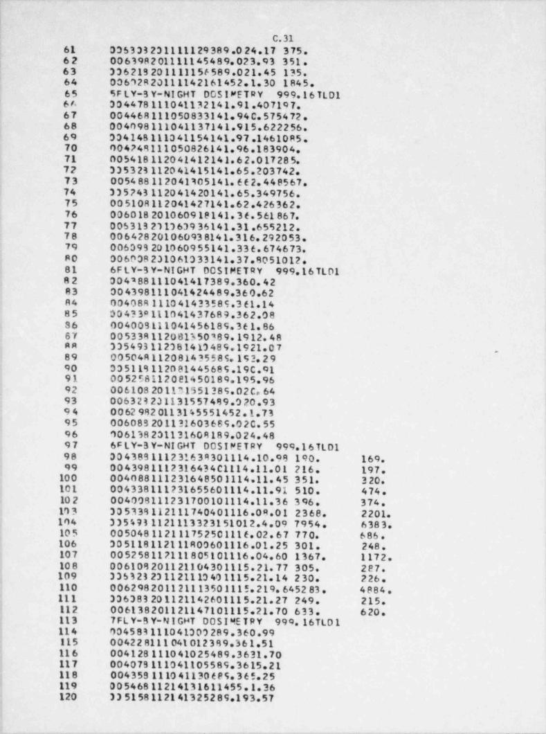
_ _ _.
C031; 61 035333231111129389.0 24.17 375.| 62 006398201111145489.023.93 351.' 63 336219201111156589.021.45 135.
64 006S2820111142161452.1.30 1845.65 SF LY-B Y-NI GHT DOSIMETRY 999.16 TL D1
! 66 304478111041132141.91.407197.67 004468111050833141.94C.575472.68 004098111041137141.915.622256.69 33414B 1110 41154141.97.14610 R5.70 004?48111050826141.96.183904.71 005418112041412141.62.017285.72 335323112041415141.65.203742.73 005488112041305141.662.448567.
l 74 335243 112041420141.65.349756.75 005108112041427141.62.426362.76 006018201060919141.36.561867.77 005313231363936141.31.655212.,
78 006428201060938141.316.292053.'
79 006093201060955141.336.674673.,
| 80 006038231061333141.37.8051012.! 81 6 FLY-3Y-NIGHT DOSIMETRY 999.16 TL D1; 82 004288111041417389.360.42
83 004398111041424489.360.62R4 00408R 1110 41433 5 8 9.3 61.1485 004?3a111041437689.362.08
{ 86 004009111041456189.361.8667 005338112081350389.1912.48AR 335493112381413489.1921.07 -
89 00 504R 1120 814 35 5 8 9.19 2. 2 990 335118112081445689.19C.9191 005258112081450189.195.9692 00 6108 201131551389.02 C. 64 -
93 006323231131557489.020.93 -,
: 94 0062 9820113145551452.1.731 95 006083 201131603 66 9.0 2C. 55
96 006138231131608189.024.4897 6F LY-3 Y-NI GHT 00SIFETRY 999.16 TL D198 304389111231639301114.10.98 190. 169.1
99 0043981112 31643 4 C1114.11.01 216. 197.10 0 004088111231648501114 11.45 351. 320.;
101 004338111231655601114.11.91 510. 474.10 2 004008111231700101114.11.36 396. 374.
10 3 305338112111740401116.08.01 2368. 2201.104 3354931121113323151012.4.09 7954. 6383.,
| 10 5 005048112111752501116.02.67 770. 686.j 106 30 5118112111R00601116.01.25 301. 248.
107 005258112111805101116.04.60 1367. 1172.-
I 10 8 006108201121104301115.21.77 305. 287.| 109 335323231121113401115.21.14 230. 226.*
110 006298201121113501115.219.645283. 4884j 111 336383 201121142601115.21.27 249. 215.
112 006138201121147101115.21.70 633. 620.113 7 FL Y-B Y-N I GHT DO S I ME T R Y 999.16TLD 1,
1 114 004583111041303289.360.99J 115 004228111 041012389.361.51f 11 6 004128111041025489.3631.70! 117 004079111041105589.3615.211 118 0043591110 41130 6 P S. 3 6 5.25{ 119 00546811214131611455.1.36j 120 335158112141325289.193.574
_ _ _ . - .- . _ . - - - - - - - . - . , . - - - - . . . _ _ - . - . . . , , . . . - . . . _ . - . . . . . - . - . - _ . . . _ _ _ _ _
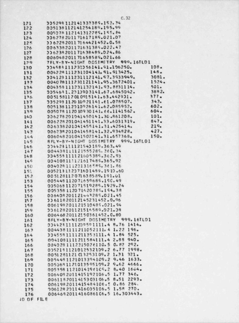
__
C. 32121 -305299 112141333389.193.34122 005138112141254189.195.99123 005078 112141312289.195.84124 306278201171617189.021.07125 33622820117164421452.0.58
'
126 006338201171631389.022.47127 336238201171638489.024.86128 006048201171658589.021.66
,
129 7 FLY-S Y-NIGHT 00SIMET RY 990.16T LD 1130 334583111231356141.91.106250. 108.131 004228111231104141.91.913425. 148.132 304123111231112141.97.3933949. 3081.!?? 004078111231121141.95.3672401. 1524.134 0043 59111231132141. 9 3. 8 e31114. 501.135 035463112013903141.67.6845042. 3882.'
,
136 005158112010915141.63.442931. 377. )
137 3352931120 10021141 61 078507. 343.138 005138112310926141.62.085952. 602.130 005078112010930141.66.1141562. 604.140 306278201041450141.30.861208. 101.141 006228201041451141.33.6031319. 847.
I 14 2 006338201041455141.31.425414. 219.143 006238201041458141.32.934828. 427.144 006048201041502141.31.657368. 150.
,
145 8 FLY-BY-N IGHT DOS IMET RY 999.16TL D 1146 334423111121543189.363.49147 004438111121555 2 89. 3 6 C. 3414 8 334559111121605389.362.93149 004108111121617489.365.92150 004029111231316589.361.E6151 005213112371601499.1913.6015 2 005128112071638589.191.01153 00544B112071650689.190.49154 00506B112071519289.1929.24 ,
1155 005358 112071620389.194.38;
! 156 00640820112194*289.021.45| 15 7 33611820112145231452.0.96
158 006198201121510489.021.9415 9 336128201121516589.021.38160 00646820112150361452.0.80
'
161 8 FLY-B Y-N I GHT DOSIMETRY 999.16T L D 1162 03442311112395o1111.4 8.76 1414.16? 0044381111211052111.4 1.22 196.164 3345531111211353111.4 1.84 525.16 5 0041081111211584111.4 2.88 940.166 004028 l'112315026110.5 0.82 292.167 0352131121012532109.2 6.77 1998.168 00 512 81121 C13 253109. 2 1.31 321.160 0054491121013394109.2 9.46 1633.170 0050691121013595109.2 9.62 4666.171 005 3 58112101419 61C9. 2 8.40 1664.17 2 0064092011415192106.5 1.77 346.173 0061182011415303106.5 8.51 2293.174 0061982011415484106.5 0.86 284.175 9061282011416005106.5 1.58 270.176 0064692011416086106.5 16.303443.
10 0 F FIL E
_ _ - _ - - - . . _ _ . __ _ _ _ , - .- - - -_ -_ __- . - _ . - - _ _ . . - . _ - _ _ ___
. . .
C.33
, 1 COMMON FINISF.NCAT,07.000Ef153.CF.TOLER CCRR.Kfal' - S C044ny R AT E (151.T I 4E( 151. E X PnS (191. P (15 ) C 4. R ESUL T , PB A R . S
5 COMMON ! Y F A R f 151, l'4 DNTH t 151, I D Av f 1514 OT*EASION RSHAL(155.0$HAL(19),PDEEP(15),DDEEP(151. NUMBER (151.hD4XI5 119 5,0tH AL Yt 15 5,00EE pv (191.Jt R I .FIhf B 3A D 6T4 o t F%/ ' p45 5 ' / ,F A IL/'F all ' /, $T AR /'**** ' /7 DE AL *e pen.CFS,50RR pcAD (9.70) NC A T,pR C.CE t SOR .NUM. CORD .TYP E
' C WR I T E ( 6,11110 11' FORMAT (1H1/// / // /20x. ' pC R$PN AL COS IM RTR Y PER FORMANCE TE STING' //3311 1 x,' A DI LOT STUDY' // ///3?x.' SocNSCRE O PY t '/22r ,'U.S . NUC LE AR REGut12 2 ATeeY Crw4 f S$10h' /////32X. ' CONDUCTED BY */22N,'PHittlp PLATn ANO13 3 JOSEPH MIKLOS'/24X ,'S CH00L OF PJ3t lC HE AL THe /28 X, 'U11VER S ITY OFl14 4 MICHIGAN. /2 7X. e eqq gRp0c, Mir HIG4 A 4 8109 8 /////18 X ,' ** * ** ** *** DES15 5ULTS OC TFST s? ***********/////l16 WRI T E I 6,12 8 PR C.CE S .SGo .NUM, TYPc17 12 F004AT (22Xe'PGCCES%nR NAMF : 'e3Am//2?r.* PROCESSOR CODE NO. : '.I1
*
1a 11//2 2 r,' TipE OF OCST wFYF R t ' . A41! Ic.1 9pi T E t o,15Cl'
10.7 ISP Fno u 4T (///////22x,' ADPp0VED av . . . . . . . . . . . . . . . . . . . . ' / / 29 X . ' D A T E'
19. ' 1 ....................')19.5 WR IT F f 6 11129 13 enoM AT (1H1./// //// 3r..r Co E ACH OnS 14 ET ER , 4 PER F00 MANCE QUOTIENT21 115 C ALCUL ATED BY t ' ////121.8 P = ( H* - H l /H' // / / 4 X . ' vHER E H= nt?? 2LIVERrn cif4NTITV'/13W.'He RFPOF TF D QU ANTITY* ///72 X,' ' /4Ne 'FOR F=95 3ArH DCpTW OF A TE ST C4'EGORY . AN AV ER ACF FERFORM ANC E QUO TIENT , P,
1 24 4 4N0' //4X.' I TS ST 4N3 4PD DEVI A f f 0N, S, AR E C A LCUL ATE 0.8 ///e4r,8 */4x) ?K 5,'A Fport$$0R P AS$ts 4 C ATEGnov IF. FOR E ALP R EL4VE NT DE /TH. /P/ +
56 6 S'/ /44 '15 LE S S THau De E QU AL TC TrE APORCPRI ATE TCLE14hCF L IMIT,2T T L.'////l,
28 wp 1TF ( 5,1414
20 14 FnR M AY (4X,eFOR P AT ECO* T E S I AND II, WHICH INVOLVE ACC IDENT DOSES.19 1L= 1. 3. FOR '//4r . 'C AT F G0p l ES TIf THRnUCH VIII, WHICH INVOLVF PR ,
| 21 ?OTECTION 00$E9, L = 0.5.'////l| 17 WR IT F ( A.151; 13 15 FORMAT (4X,'IF A DOS!"FTER IS LOST. NOT oF00nTED PY THF Po 0C E S SO R .
1'
14 1 IRp 49t ATFn'//4 v,' f 4pp0pcRLY, ETC.. THF hCR0 " VOID" AP8E ARS NExT T!
2820 THF OrSIWFTER NU4 RFR. '//4W ' VOIDED DOS I *ETERS AoF NOT INCLUDFD I
{ 16 3 N THE 04 S S/F AIL C ALCUL AT IONS . '//// lST WRI T E f 6,561 i
SA 5A 80R M AT (4v,eS0pc INCONS IST ENCIFS CAN 9F NOTE 0 IN THE C ALCULATIONS19 10UF TO TH F ' // 4X .* NU 4R ED OF DIGITS PRINTFD FOR FACH NJ "R E F. C ALCUL,
s 40 2 4T IONS ARF' //4X.' ACTU ALL Y 440E hlTH FIGHT SIGNIFIC ANT FIGURES FOR41 1 F ACH N'J"9 FR .' l4? 00 16 i len=
4' Jtli =0 I44 16 Kill =145 K f 31 = 0
i 4e KfAl =0! 4T Kt T I =0
4R GO T O to'
40 101 RE AD(5,20,rkn=ol NC AT.p*0.CES .50R. AUp CORD, TYPF50 20 FORM AT 111, AR.T3.1x r?.1,44)e'
51 10 J( NC ATI 1=
97 CO T O i t ,2,3 4,5, A. A ,61, NC AT51 1 RE40 f5,21) (NU4R ER ( I I . l YF AR i t t e lMONTH( 11.104Y( f l .
} a4 1 R AT E(! ) .T i >F( I I,ROEE P(I I . T = 1.1511 99 71 FORMAT (19,$!2,7*.2F5.0.F10.01i 56 C ALL ST ART (NU4 pes tj $7 TnLFR = 0.3i
f
_, - - - . - - - - - _ _ - -
_ _ _ _ _ _ - _ _ _ _ _ _ _ _ _ _ _ _ _ _ _ _ _ .
C.34
SR CX = 1,1459 CALL TEST (RDEEF,00FEPl69 WelTE (6,??) OT6? ?? F00M AT ( 1 H1,14 X , ' C AT E GO D Y I ACC IDENT , L Oh-E NE RGY PHOTnhS' /15x ,'62 1R ADI ATION SrupCE : x-Ray TFCHNIQU F NFI' /15X,'IRR ADI AT13N 01%TANCE61 2 : 100 Ce r0RRErTES Th ' ,F 5.1, ' C P' / / l#4 WR IT F ( 6,231 OPC.CES 500,NUw, TYPE69 21 FORM AT (15v e PnCCcS500 NAMc : , ,3 Ae /15x,*pp0CESSOR CODE NO. t ',13A6 1/15X,'TYPC CF DCSIMETER ',A4///l67 C ALL ST0pi lDCE FD,00FE P, NUu9F R,5 )6R GO TO 10069 ? P F AO 15,281 (NUMBER ( I I, tVF A2 ( I),IMONTH( I l ,10 Av t ll , R ATE l l t70 1.T IMEt I I,40EFPt !) , ! = 1,19971 24 FO R M A T f 15,3 I2,5x,25 5.0,F 10.0172 FALL ST ARTi bOMR8p l7' TOL8 0 = 0.174 Cu = 1.017= CALL TESTIOCEEP.DCEFoi7e WR IT E f A,7a l GT
' 77 20 F row AT (141,14 x ,' C AT E GOR Y ll * ACCICENT, F I GH-E N E R GY PHOTONS' /15 x78 1,'D A0! AT ION SOURCE :
T C e ,r i . g , , I UM-13 7'CFS /15Y,' lu P A01 At t0N DIST AhCE : 10 0
70 2Cu CcqRfCTce Cge f f t
PC hoITS te,51# Ppt Cc%,500,Ntv TYpfal C at L %T 7p it o DF E D,00E F D, NUMaE R e ll82 Gr TC 10091 3 PFAO (5,101 (NU DRC1 t ! ),1YE A0 f i l f wC AT Ht II ,1C AY( II, R ATE t ! ), TIM Et l i94 1 RSH at t i r n CEFoll t, t = 1,1518% 10 FO RM a' t l 5 , $ 17,7 w ,2 c 5.0, P r 10 01m, CALL ST an T I N94 B Eo lAT T rt F s = 0. 5Fe CV = 1. C?Ao CML Tc tT r p % FA L ,0$ Ha t tep NoAGt 1=
o! WDITE t6,311 NPAGF, DTc) 11 FO A * AT (1H1,1*w.'CATEGO'Y 111 : LOW-ENERGY PH070NS' ,20 x , ' P AGE ' ,Ics 11. , Oc 2e /15x e .n A71 AT ION SOU nCF : x-qAY T EC HN 10tt! L-l ' /15X,'IDRA94 ? DI AT ION DISTANCE I 200 C M CO R R E C T E D TC ' , F 5.1,' C M' // les Wo lT E (6,210 PP C.CE S.SOR NUM, TYPEcA CALL STCp1tRSHAL,0$HAL,NUMpFP,hPACF)47 rv = 0,77os CF = 1.099 C AL L TF ST t PDEF P,00c Epl
100 NP AGE = 2101 We l T E ( 6. 311 hpaGE, DTj107 WRITE (6,211 p p C.C* S . SCR , NUM, TYPE103 C ALL ST CP1( RDFEP,00EE8,NUMBFR NPAGe l1C4 Gn TO 10010 9 4 REA0 15,741 INUM9ER i t t e lVE AR f I I,I PCh THil l ,10 Av ill en AT E(! ),T I45 t t lIce 1,ROFEPtII, I= 1,1511C7 CALL STARTINLMBERI10e TOLEO = 0.5104 CX = 1.03110 C A LL TE STf RDEE P,00c EP)111 WPIT E ( 6.371 GT11? 17 FO?uAT (1 H1,14 y ,' C A TEGO'Y IV PICH-ENERGY PHOTONS' /15x,*pAOIAT10111 IN SOURCE : C E S I U4-13 7 ' /lix,'IRR ADI ATION CISTANCE 100 CW CORPECT114 P E D T C ' ,8 5.1,' Cw'//l115 WelTE (6,719 PR C,CES ,50G MJ M T YPE116 C ALL ST CP1t PDE E P,00F EP, NUMBFR ,2 0117 CD TC 100
1
_ _ _ _ _ _ _ _ _ _ _ _ _ _ _ - - _ _ _ _ _ _ _ _ _ _ _ _ _ _
m
t C.35
||
I
( 118 5 R E40 (5.70 ) I NU#RF 8 t l i,1 YE A# t l i .t "0NT H( l l ,10 AYl il,R A TE t l i . TINE ll i'
11 e 1, # $H AL f i l . ~ I = 1,1511?n 70 FOR M AT I I 5. ?I 2,4 *,25 9. 0, F 10. n l121 C ALL ST Aef t hu= rep l17? TOLE 8 = 0.51?3 CM = 0.966"124 Catt TE ST t pSH AL ,0SH AL I125 WRITF t6 1RI
-12e la posg AT ( tul,14x,,C AT8G00 Y V RE TA D AR Tir LE S' /15x,' Rant AT10N SOUR127 1CE t STR CNTIU4/YTTRIUw-90 '/154,' Iso An I AT IDN DIST44rE : 35 CN'//l,
!?m walTF (4,2?l #pC CES.509,NUM TVpE120 CALL ST CP1( RSH AL.C5H AL .NUNRER .41. .
<
I'0 GO T C I CO131 6 RE A9 (5,711 (NU4RE4 5 l i e t vE ARi t t e l urNTH f f ) ,I n AY t ti .R ATEl l i,TI ME (I I,137 1 I = 1 15113 71 FORuaT (15,312 *r.2F 5.01134 rF = 1.n115 .tr252 = 1.0ISA CALL STARTINU4RF11117 TOLER = 0.5ISR 0" 72 1 1,15 .
= '
1q e4TF(Il = D AT E t l l *C F140 F E POSil l R AT E lll*T I*El l)=
141 09 Half i t ENDft(j)$1,Q3|
=
142 72 00FEpft) CSNattil= '
14? IF INCAT - 71 R1.82,R2144 81 WRITE (6.7'l nT148 72 FOR M AT (1H1 16r,'CATEG08Y VI * HIGH ENF8GY C0400NFNT e ,18 N. 'p4Gr 1146 10F l'/ S ot .' CF PPCTCN "I X TUDF5 '/19 Y . '# 401 A T ICN S DJ RC E * C IS I U9- 117'147 > /18 4, '120 A014T 19N S IST A Nr c 106 Cd C Co nE CT ED TO ' , F9.1.' C M' / /l-
its GO TC 4414c 32 woITE (A.R*l nT19n R5 F0e * AT (1H1,14r 'CATEG0cY Vil : p uninN CowaqNF NT* .17r,'P AGF 1 0F 3e
151 1 * /13 X , ' r F pHO'"AM 01 U$ PE T A p aoTICL ES'/15 X, *R A014 TION S0ue rE : C ES1** ? lum-137' /19 3. ' I Re A01 A f g nN DI ST a NC E * ICC CW CORRECTED TO ' eft.1,15? 1' CW'//l154 GO TC m'4155 R3 WR IT F te.968 OT156 R6 Fn94 AT E1H1.14W e' CAT FG00Y Vil! * PHOTON C0"PnNENT'.16X,'pAGE 1 nF197 13' / 31 Y, 'OC DHOTCNS PL U$ NEUTt0*S' /15X,'P Ant ATION SOURC6 CEStil*-119R 2 37' /15 * ,' Io R AD I AT ION OfSTANCE * 100 CM CoppECTr3 TO ',F5.1,' CW'//189 *)1e0 54 We lT E ( A. 2 31 PE C.C8 5. 508,NU4,1vpE161 CALL ST Cpi t CS H a t . 00F F P, NU Ma E 8. 51le? READ f5,701 NC A1 Pe 0.CF 5 50s ,NUM. CORR TvP F1** IF (NCAT - TI 90.91,02184 90 #FA9 (9,30) (NUpXf i t ,1YF At t II 140NT Hill e lC4Yi II,R ATFil l . TIwE t t i,RS165 1Hatfil,90EEPflle ! = 1,151166 CF = 2.0167 CVS = 1.0216R Crn = 0.72les GO T C 4 3170 91 # FAD (5.878 (NUMX(II,lVEAptII.!* CATH (II,1CAYllten AT Fill, TIMEl li, RS171 1 HAl t ile RDEF 8t ! ), I = 1,159172 87 FORM AT ( I 5,312 .4M .? F 9.9. 2 510. 01
! 171 CF = 3,0174 CMS = 0.966 5175 C WO = 0.0176 GOTO9?177 92 #EAD tie 2RI (NUut t i l . IVE AR( II, IMONT Hil l,I C4Y( Il e R AT El l i , TIME t I I RD
- _ _ _ _ . .- _. _ - _ . . . .-. . - . . ,_ .- . - .. - - . _ , .- - _ _ ~ . - -
_ _ _ _ _ _ - _ _ _ _ _ _ _ _ _ _ _ _ _ _ _ - - _ _ _ _ _ _ _ _ _ _ _ _ _ _ _ _ _ ._
C.36
17R 1EF ot II, I 1,1 *l=
170 C8 5.0=
1A0 CXS = 1.0let CXD = 1.0182 9? CatL StaRTthU4XI183 DO 74 1 = 1,151A4 IF INJ9 PER I II .EO.NUSxt l l l GO TO 76195 wn ITE ( 6.791 NU"BER (11, NC AT
146 75 80AMAT (1H1,4X , 'W AG NING * * * nO SIME T EE NuueER',15,' IN C ATEGODY ',1
197 11/1TX,' HAS A0 " ATCHING DOS IMETER 9 f"Brc ' l
188 GO Tn I COleo 7' PATE(!) = R ATEl 1) *C 5
R AT Fill *T IMe t t i1c0 FxonStil =
EXPC$til*CXS19 1 DSHALrtil =E X pC$ t i l *ry nle? 74 CDFEPYt11 =
Ic3 lc INCAT - 79 94,95,96104 94 WoITF 16,77) DT105 77 F0 8 4 AT (1H1,14X,'CATSG90Y VI : L0 b- ENED GY CO MPONE NT ',14 X ,' P 41E 2 0to6 1r 2,/20X,'CF pHCTEN NIXTUDES' /15x ,' R &DI AT ICN SOURCE * X-G AY T ECHNIICT 7 0 IF L-l' / la r,' I RQ 401 ATION DI ST ANCE 2 200 CM CODRECTEn TO ',F5.1,'
icF 3CM'//ltoo Np4GF = A
2C0 G9 TC 07231 o% bDITC ( A, pol167 sc FAD 1AT f lH1,14w ,* C & TECOR Y Vl ! t * ETA D AF T IC L E COMP 9 AF hT ' ,10r, ' P AGE201 1 7 05 3'/3)x,'0F 04670N5 PLUS mcTa otoTICLES*/15X,,et91 Tl0N SOURC904 SF : STRnNTILp/vTTRiou-90*/19x,,ranaCIATICA CIST ANrE 35 CM'//l26 5 ND&GE e
?Ce GO Tr 97pot 95 WolTF t6,qag ny
7se va FnRu ai (1H1,14 X ,' C 4T FG92 Y Vill 2 NCU1D*9 COMPONE NT ' ,15V, 'P AGF 2 0F
209 1 S* /11x ,' nF pHCTON$ PLUC NFUTRONS'/15h,'RAOIATION SOURCE M1 D Ea A T
210 ? ED C AL I FnoM lUd- 23 2' /1%= ,'IPE ADI LT10 A DI ST ANCE t 50 Cw rnsar*TED TO
211 5 ',F4.1,' C "//l;17 NP&GF = 071$ O' WD IT E ( 6,211 PP tercS,$"D Nuu, TYPE
714 C at t ST0olt CSH A LX ,00FF PX, NUMBE o ND AGEl215 Ir ( NC 4 7, NE . 91 GC TO 46
21A CF25? = 1.3217 WolTE t6,479
71a 47 FoouAT t///' NOTE * 0* LIVERED DOSE E0'li v eL ENT INCLUDE S A Gaw"6-R APlc I V C nNTRI BUT ICN' /9r ,' Fpn* T He CF-257 SOURCE EQUAL TO 0 3 CF THE NFU??0 2700N 00 SE ' / c y,' FOUI VA LE NT SH OWN APOVF. T F I S CONT R I BUT 10 h IS I NC LU2?1 3nED IN' /9x,'THE TOT AL nFLIVFDF9 NOSE E00! v4LFNT SHOWN ON THE NEXT2?? 4 PAG 8.'l?'3 46 00 78 I 1,15=
224 DSHalt l i = CSH AL(!) + 09 hat x t il*CF252??5 74 00rEpt l i = 00EE ot t i + 00EEPv t ll*CF?S2
??* IF IN C A T . EO .81 GO T D 552?T C AL L TF SY t o SH AL ,DSH All??B 00 90 ! 1,15=
??o PATEllt = PtilRSHAttil?$1 TIMFill =
731 90 ErP3 Si t t = 0$H4 Li l l752 OT = P9 4 02$$ CF = $714 COR4 = p*SULT
??" CM = FINISH296 55 CALL TESTtROFrP.DDF88)237 IF INCAT - 71 40,41,42
- - _ _ _ _ _ _ _ _ _ _ _ _ _ _ _ _
_ _ _ _ _ _ _ _ _ . _ _ - _ - _ _. . . . . . .
C.37
2*n 40 WRITE (6.70)210 79 FOR u AT # 1 H1,14 x , ' C 4 T E nn R Y VI t SUMMARY OF PHOTON MI XTURF S' ,11X ,' P424C 1GF 1 Oc l' #/ l241 N0 4r. E = 724 2 GO TC 43242 41 WRITE (6.44)?44 44 FORM AT (1H1,14r er4TEGORY VII t SU" MARY OF PHOTONS PLUS' 10X ,' P4GEe
245 1 3 nF l'/3)X,' PCT 4 PARTICLES'//l246 NpAGE = 7247 GO Tr 4124a 42 watTE I6,491149 49 FDs1 A7 ( 1H1,14X ,'C LTEr92 Y VII I t SUMMARY CF PHOTONS PLUS NEUTRCNS'2 * ", 1,5X,'p4GF 1 CF 3'//l291 NoAGE = 1029? 41 WolTE fA,22) 0FC.Ces 960,Ntsu,7vpE29' CALL t'OpitPCEEP,00EFD NUMBER,NpaGEl'94 GO TO 100295 o or 17 i = 1,679A FINill = 84 IL797 tr (Mill.EC.29 FINtil.0455298 17 IF (Jtil.FO.01 FI Af f l=ST AR2'4 bp!TF teolag2^0 19 FqswAT f t pl / /// // /29 W , 8 * * * *= * =** * SUMMARV 0F S F S UL T S **********'761 1/////t2A' W81 T E (6,121 *PC,CE S ,tre NUM,74pE?'' ketTF (A,lol (FINtfl, I = lo ng264 19 FCGMAT t / // //171,'C e TFGCpv 1. ArCIDFNT, LCW-EN ER GY PHOTCNS *265 1,44//17v,'rAtcGroY !!,
ACCI DENT , HICH-FNERGY PHOC ATEG0pv IVTONS ',44//17X26E 2,'CATFGnov !!T, LOW-cNepGY PHOTONt',14X.44//17N, . HSAT l ir.H *Mc cG y owc TCN S e ,1'r ,4 4//17 x ,' ca T c GC R Y V, RET A P ARTICLES',192Aa 4v,A4//17r e,CATFCORY VI. PH0 TON HI f TtlR ES ',17X, A4//17X,' CATEG08Y Y26o 511. PHOTON! PLLS 9?TA PAPTIOlFS ', A4 //17K,' C AT CG0pY VIII, pHO27$ 6 TrN% PLUS NEUTP CNS' .11t ,44// / /l271 DO 90 i = 1.R27 2 Ir te!Nift.FC.STARI GO TO =127' 53 CONT I MJ E274 Go TO 5727= 91 WRTTF ie,9 127A 53 F OR w a' (17 r ,8 6 > ** DoorFSSOR OIO NOT P ARTI CID ATE'/ 22X,'!N THI S C A TE277 1GCRY.')27P 52 WRTTE (A,941275 94 FnA W AT (1H112aC STOP?eg FNn282 Suman'171NE TEST (Rep,0rt l283 COM*CN F IN I S H, NC AT,nT ,r 3DF t 151,C5.TOL ER ,r C a p, K l al2a4 C0guCN R AT E (191.T !*Ft 191. E XPOS f 151,P t 151 C F.R E SUL T, PP AR,5zoa DATA PA CC/' p AS$ 8/,C AIL /' F AIL 8 /2ag clu gN93cN R Epl151.0 Ell 19928' TCEL = 0.02e a TP 0.0=
289 DF NO" = 19.0toe IF I NC A T.GE .61 GO Tn 242 91 DO ?? I = 1,1=202 0475 tli = R AT Elll*CF
k 203 Expo $t t l = RATE tt le TIMF ill204 22 DSL f il = FXPOS i ll*C Y2c= 24 DO 14 i = 1,1514e Ptfl = 0.0297 IF (OFL(11.EC.O.0) CD TO 70
_ - __________- ---
C.38
-
29m Ptil = taEPiti - DElfill/DEttIl299 70 IF (C00El ll .LT .9.01 GO TO 13300 DENOP = DEhCW - 1.0301 GO TO 34302 33 TDEL = TOEL + OEL (1)303 To = To + Pill?n4 34 CON T IN U E30 9 Pmap = To/ DEAR *
?C6 HOLD = 0.0367 no 2* I = 1,153C P 15 ( C00Ef t l .E0 9.01 GO T C 2130 0 HO LO = HCLO + tptti - * Baal **2
310 23 CONT IVJ F211 5 = 50RT t HrLD/ t CEN04 - 1.019312 P F50t T = Ap$tPRARI +$
213 F I NI SH = PASS314 f r l'ESet T.GT.TCL*R I FI NISH=F AIL315 IF ( FIN ISH.EQ.P a$$ $ KINC AT l=K (NC ATl +1314 RsTURN .
117 END31R SU9 R CUT INF ST AR T INUM BFo i*? 1 Co"10N FINISH,NCAT,nT,C 00E t1* l CF ,T OL E*, CC# #120 014cNSICN NL49Ent193?>L 00 9 I = 1,15
0.0SS2 000EtII =S?1 IF INUMBER I II.LT.900001 60 TO 9
/ ??4 COnFill = 0 .0??! NUMBErfil = NUM?F#fil - 9000032^ * CONTivJFS27 N = C8?2a c) To i1,1,7,1,1,4,4,49,NC4T32C 1 Di $T = 100.1
: 530 GO T O 10?*1 2 Of5T = 200.C?32 CO TO 10325 3 Cr = 1. 0534 Gr TC 11315 4 GO TO ( 1,2,3,5,5 8, N316 4 nt%T = 90 03?7 10 DT = DIST - CDPe
(DIST/Cil**2?2m C8 =
3?e 11 RETuaw'4C Est n141 $U98 00TI N8 STCP 1 t RE P . DEL, NU 48 ER, N P A GE )342 COMMCN FINISH,NC AT,DT C00E t 15 ).CF. TOLE * , Cape ,Et 99*
34' Cn*4CN D AT F (191,TI 4? (19 9 ,Eup05 (15 ), P t 151. cx,R Etut T , p p an ,5:
| 344 Cn44nN IvEARt15tel40NTHt151,IDAYt15)! ?45 DIMEASICN O FP t151,0Et t 191. 5T AT E t 15) ,NU"BER t 15)
346 OATA OK/' ' / ,VCI D / ' VOI D ' /147 DO 33 1 = l e 15.
14P STATEtti = Cui 144 IF (C00Etti.EO.e.08 STA TF i l l = VOI O
350 13 C CNT INU F351 GO TO t 20,21,22,23,41,44,46,94,57,711 NP AGE
352 20 WRITE (6,641 CR353 A4 F O R 4 &T (7 3v ,' t a p ADI AT ION INFORM Af l0N ',3K , 'S PALL OW DDSE E CUIV, C4 =?54 1 ',F4.21359 CD TO 2 93'e 21 We l T F ( 6.40 ) C E397 40 FORMAT (214,'I pe Ant ATION I N5 0R w AT ic h' ,8 X , ' D E E P DOSE E0JIV, CX = '
1
l
. _ . .- . - -. . _. .._- - . - -__ _ _ - . . _ _ _ - -.- - - - - -
_ _ _ _ _ _ _ _ - _
.
C.39
?5F 1,54.21?54 GO TO 293A0 22 WR IT E f 6.241 r y361 24 F0#4 AT (23X ,'IF R ADI AT inn INF O RM ATION DEED AB500Rc0 DOSE, C X = ',367 1F4.21365 GO TC 29364 23 WRITF IA,6*l165 65 FORM AT f 23Y ,'IRR A014 TION I NFORM ATION' ,3X ,' SHALLOW DCSE E CUIV, CB=33ee 1.96 A 5 ')1A7 So We !TE t e 2 53 |
I368 25 FOR4AT l' 0051M ET Ee ' ,4X, * 0 4TF ' ,6 X, ' R ATE ' ,5X ,' T I MF TOT A L' ,6 X , 'DFL169 LIVEDED RFFCRT E0'l370 GO 70 f50.9C,51,83), NPAGF371 50 WRITE (6,26l377 26 FnRMAT t' hU"REO IRRADIATED (MR/4INI (MINI ( Ma l',7X, e (4R FM I
173 1 (MR841',6X,'8'//l?74 GO TC 92$75 51 WDITc (6.661376 66 Fn R M AT l' AU4REn I po &D! aTED t R/4 T N 3 ' ,4 X ,' l 4T NI ' ,3 4,8 ( el ' ,0X ,' ( 4
317 1 Ant ' ,AX ,e t R 40l' ,6X,, pe f f t
??* GO TC 92379 52 WR IT F f 6,671
3R0 67 FnomAT l' NU* P ER 1R8 ACI ATFD (MRA0/ MINI (4INI (WS AOl ' ,7X,' ( MR F M I
381 l',6X,'fMRE41',5X,'O'//1se2 -52 15 thCAT.GT.2) CD T O R33a1 WR IT F t A,R? l I huw98R(!l,ST ATE til ,IYF Ap f t ),1MCNTHIII,la4Y til .RATc f! ,
?a4 I I .TI net ll EXRn$ til, DEL (II, REP f llv Pf f l e t = 1,151
?85 82 50Rw ST (1 X ,15 13.4 4,1X,12, ' ' ,12 ' ' e l 2, F 8.7,51C. 2, F 6. 2 1Y.
'a6 1F9.3,510.3,F10.4/l197 GC TC R43RR R3 WR IT E t 6,851 t hum 8FR t t i,ST ATE t il ,IV E AR t il,IMCNTHill,ID AY (II.R ATE (
3Ac II I,T IME ll i, EXp0 S t i l,0EL ( I ) ,R E p t il eptil. I = 1,15)
Ser R* FORM AT (I X ,15,1 X , A4,1 X,12, ' ' , I 2, ' ' ,12, F9.1,8 8. 2,F 8.1.513.1, F il.
391 11,50.4/3S42 84 WR IT E (6,271 PP AD S e p FSULT,TOLER ,rI NISH39' 27 eno4 AT t / / 6 e X ,' ' /6 6 X ,' P = ' , F9.4 // 6 6 X , ' S = ' , r n .6/ e 1 X, ' ' /6 0 X , ' ."*
SQ4 1/ + 5 = ' , F E .4 / #6 6 X, * t = ' ,F 8. 4 / / ^ 0 ) , ' * * * * * * 8 , A4 ,' *******),
3c5 GO TC oe59e 41 C X % = 1. 03307 CX O = 1.n3?C8 GO TO 4 4?90 46 C X S = 1. 0 2400 CYD = 0.72
l 401 49 WRITE te,4?) CNT, C XDl 407 42 FORW AT ( 48X ,'DELIVEREO OOSE ECUIV AL ENT' /23X,' t eR ADI ATION INFnoMATI
433 1 CN' ,5X , ' S H att 0W ',6X , e nE F P' /' 00$ 1 McT FR ' ,4 X, 'D4T E ' ,6 X,' R A TF ' ,9 X ,' TI4C6 2ME TOTAle,gx,eCX ' , F 4. 2,3 X , ' r Y = ',F4.2/' NUM9EP IRR ACI AT FD=
409 3 (#R/ MINI (4thi ( MR I ' ,7 X, ' ( 40 E M l ' ,6 X ,' ( wo F Ml' / /l
436 GO TO 49:
| 407 54 WRITE (6,56140R 56 F enw AT (48X,'DEttVE# FD DOSE FOUIV AL ENT'/ 23X,'IRR ADI ATION INFORMATI409 10N ' ,5X ,' S H A t t0W ' ,7 X,' OE s p' / ' 0051"ET Fo ' ,4X, ' OAT E' ,6 X, ' o ATE ',5 X , ' T !410 2ME TOT AL ' ,5X , 'CR=0. 96 65 ' ,5 X , 'Ca =0.0 8 / 8 NU4RER Ino ADIATE0 (MRA411 30/ MINI (MINI ( WR A0l' ,7X, ' t MR EM I ',6X ,'(MR EM I' // l
412 GO TO 55413 57 W R IT E ( 6,5 8 )
414 54 FORM AT f ? 3 X ,' !R R ADI A TION INF ne4 AT ION',2X , 'OEL IVE RED D3 5E EQUIVAL F1419 1T' /' DO SIM E T E* * ,4X,' 04TE' ,6X ,'R ATE ' ,9 X, ' TI M E TOT AL' ,5 X ,' SH4LLOW'
416 2,9X,'DEFD'/' WU46ER IRRAOIATED (MDEM/ MIN) (MINI (MQEMI',6X,'(MR417 3 E 41 ' ,6 X ,' ( "R EM l ' / / l
_ _ _ _ _ _ _ _ _ _ __
C.40
41R 55 WR IT E ( 6,43 8 ( NU4PER f f t .ST AT Et II, tYE art il,IMONTHt II ,IDAYt II .R ATE t t41 9 19,TI MFt i t ,E XPCSII I RE Ptil ,0EL f il , ! = 1,151420 41 FosM AT ( 1 X ,15,1 X,4 4,1X , T 2. ' ' ,12, ' ' , I 2, F 5.1 F 8. 2 ,F R.1.2 F12.1/1421 GO TC 094?? 46 WR T TF 16.479423' 47 F0844T ( //18 X,' TOT AL SHALLOW 00SF FOUIV ALENT',4X,' TOT AL DEEP DOS4?4 1E EOUT V AL ENT' /3 ),' D05t wF TE 8' ,6X ,' tFLIV ER EO RE PORT E D',15 X,' CEL IVEo F429 2 0 R E POR T F O ' /4 X , 'N U19 E R ' ,10 X , ' i W# E * ) (MREut*,9X,'P', 9X,'fMRErl42e 3 (MREul'eaX,'D'//l497 WRITE te,'RI ( NLaRER i ll ,ST ATE (I I .EX F05 t II .T IME lli, q aT F t ! ), DELill42R 1 ,REptII,*til, ! = 1,151
.42c 4R Fop 4AT ( 4 X ,15,1 X , A4,5 X, F7.1,2 X , F7.1,2 X, F9.4,6X , F7.1,2X, F 7.1,2 X,F Q.4*P 14/l421 wA IT E (6.4# 1 DT ,P RAR .Cc.S.Cr# R .RE SULT ,TOL FR TOLER,C X,F IN ISH417 49 FOR M AT t / /3 3 X ,' 8 ,3 2 X ,' ' / 33 X ,' o = ' ,rg.4,20X,' P = ' , F9. 4/ /13 X, ' S411 1 = * , Fo. 4 20 X ,' S = ' ,F o. 4/ 78 X , '-' ,3 2X ,' ' /2 7X,' /p/ * $ = ',FO.4 144'4 2 X, ' /P/ + 5 = ' , F9.4/ / 33 X ,' l = ' , F 9. 4,20 X , 'l = ',F9.4//28X,'******415 3',A4,8 ******',15X '****** ',A4,' ******'t416 GD TC 00417 71 WR I TE t e ,7? '
41P 72 FOP 4 AT t //1sX,' TOTAL DEE P DOSE ECLi b ALENT* /20X ,' DOS IMCTE R',8X,'OEL4$4 l lV E8 ED RE PORT FD'/ 21X,8NUM9ER ',12X,' IMaEMI ( MP E NI ' ,7X ,' P' //l440 We T T E t e . ge l g ktwRg eg II,5T ATE f f l CFL t il.p Ep(!), Pt il, ! = 1,158441 50 FORM AT ( 21 X ,15,1X ,4 4,7X , F 7 1,2 X , r 7.1,2 X , F 9. 4 / 3447 t* TTE f 6,701 P P AR ,5, R ESULT .T OL E R , F T WIS H441 70 F004AT t//52X,' '/52X,'P = ' ,8 4.4 / /52 X,8 5 ' = ' ,F9.4/ 47X ,' ' /46 X,' /P444 1/ + $ = ' ,F 9.4/ /52X, 'l = ',Fo.4//47X,'=***** ' , 4 4 , * * * * * ** ' l445 90 PETUAN44A ENn
END OF 6|Le
|
................................................... ....-....................... .........
t
C.41
PERSONAL CCS IMETRY PERFORM ANCE TEST ING
A PILOT STUDY,
,
!
S FONS ORED BY :*
U. S. NUCLE AR REGULATORY CCMFI SSIGN,
i
i
!I
CON DUC TED B Y :1 PHI LLI P PL ATO NW D JOSEP N M IKLOSi SCHOOL OF PUB t.IC HE AL TH
UNIVERSITY OF N ICHIGAN{ ANN AP80R, MICHIGAN 481091
i
i .
ij ********** RESULT 3 OF TE ST # 3 **********
it
!
I
i- PROCE SS CR NAME : F LY-BY- NI GHT DOS IM ET RY!
! PROCESSOR CCDE NO. : 990:
! TYPE OF 00SIMETER : TLD1!.
!,
| . . .a. 6.?P. . . . . .j APPROVED BY .. . .
DATE . . .b.4.W. . . J . . .h.k.
:i
i
.
- - - - . ,
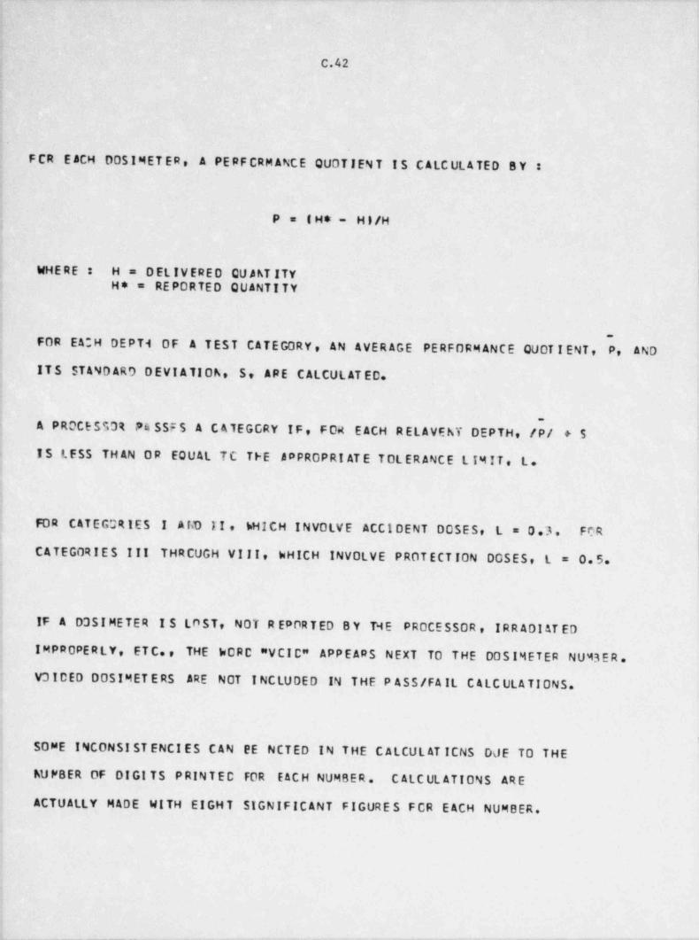
_ _ _ _ _ _ .
C.42
FCR E ACH DOSIMET ER. A PERFCRM ANCE QUOTIEN T I S CALC ULA TED B Y :
P = ( H* - H)/Hi
WHERE H = DELIVERED QU AATITY !;
H* = REPORTED QUANTITY
<
~
FOR EA;H DEPTi 0F A TEST CATEGORY, AN AVERAGE PERFORM ANCE QUOT I ENT, P, AND,
,
; ITS STAND AR9 DEVI ATIOA, S, ARE CALCUL AT ED.i
-
A PROCESSOR P4 SSF S A C ATEGGRY IF, FOR EACH RELAVEhY DEPTH, /P/ +$e IS LESS TH AN OR EQUAL TC TFE APPROPRI ATE TOLERANCE L IMIT, L.
1
I
i
i FOR CATEGORIES I AliD II, bHICH INVOLVE ACCI DENT DOSES, L = 0.3. FCR,
CATEGORIES III THRCUGH VIII, hMICH INVOLVE PROTECTION DOSES, L = 0.5.
IF A. D3SI METER I $ LOST, NOT R EPORTED B Y TME PROCESSOR, IRR ADI AT EDi
I M PR OPE R L Y , ETC., THE WORC "VCIC" APPEARS NEXT TO THE 00SIMETER NUM3 E R .!
V3 IDED DOSIMET ERS ARE NOT INCLUDED IN THE P ASS /FA IL C ALC ULA TIONS.
SOME INCONSIST ENCIES CAN EE NCTED IN THE C ALCUL AT ICNS DJE TO THE
hUPBER OF DIGI TS PRINTEC FOR EACH NUMBER. C ALC UL ATIONS ARE
ACTUALLY MADE WITH EIGHT SIGNIFICANT FIGURES FCR EACH NUMBER.
_ _________ - - - . - -. - _ _ . - - - -. -- --
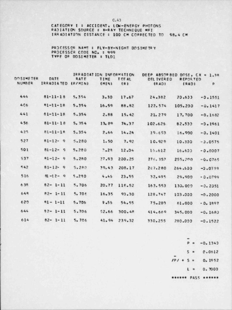
--_ _ _ _ _ _ _ _ _ _ _ _ _ _ _
C.43C AT EGORY I : ACCI D E NT , L OW-EN ER GY PHOTONSR A31 ATI ON SOURCE X-R AY TECHNIQUE MFIIRR ADI ATION DIST ANCE : 100 CM COPRECTED TO 98. 4 CM
PR3 CESS OR NAME : FLY-BY-NIGHT DO SIMFTR YPROCESSCR CODE NO. : 999TYPF OF DO SI METER TLD1
IRR ADI AT ION INFORM ATION DEEP ABS 0* BED DOSE , C X = 1.3800SIMETER DATE R AT E TIME T OT AL DEL IVER E D REPORTEDNUMBER IRR ADI A TED (R/ MI N) (MINI (R) (R ADI (RAD) P
| 444 81-11-18 5.354 3.30 17.67 24.382 70.633 -0.1551l
l 406 91-11-18 5.354 16.59 88.82 122.574 105.200 -0.1417|
441 81-11-18 5.354 2.88 15.42 21.279 17.700 -0.1682
4 56 81-11-18 5.354 13.89 74.37 102.626 82.533 -0.1961
425 81-11-1R 5.354 2.66 14.24 19.653 16.900 -0 1401,
527 81-12- 9 5.280 1.50 7.92 10.929 10.300 -3.0575
501 81-12- 9 5.200 2.28 12.04 16.612 16.633 -0.0007
S37 R1-12- 9 5.280 27.93 200.25 276.35? 255.P90 -0.0765
542 81-12- 9 5.2P0 ?9.43 208.17 207.280 264.500 -3 . 0T 99
516 81 -1 2 - 9 5.280 4.45 23.55 32.495 29.900 - 0.0799
638 82- 1- 11 5.706 20.77 112.52 163.553 130.000 -0. 2051
649 82- 1- 11 5.706 16.35 93.30 128.747 103.000 -0.2000
620 91- 1-11 5.706 9.55 54.55 75.280 61.000 -0. 1897
644 92- 1- 11 5.706 52.66 300.4R 414.664 345.000 -0.1680
614 82- 1- 11 5.706 41.94 239.32 330.255 280.000 -0.1522
-
P= -0.1340,
S= 0.0612.
/P/ + 5 = 0. 1952
L= 0.3000
****** PASS ******
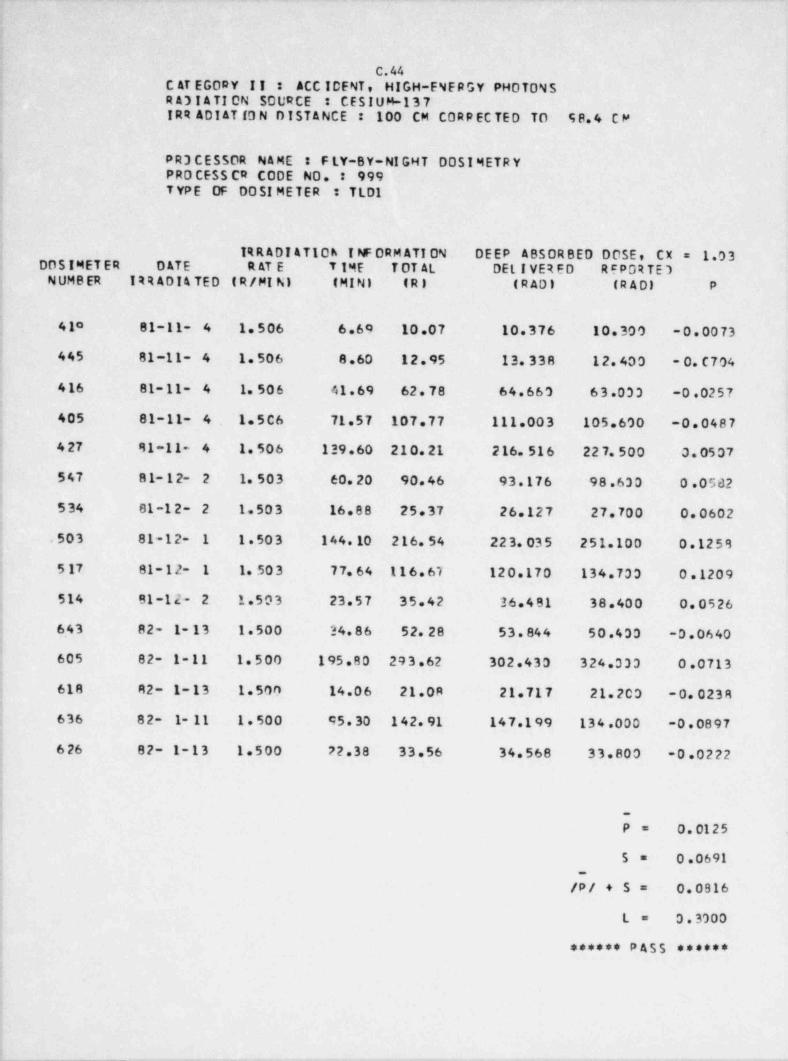
C.44C AT EGORY II : ACC ICENT , HIGH-ENERGY PHOTONSR A3 t ATION SOURCE : CES I U M-13 7IRR ADI AT f0 N DISTANCE : 100 CM CORP EC TED TO 5 8. 4 C M
PR3 C ESSOR NAME : F LY-8Y-NI GHT DOSI METR YPRO CESS CR CODE NO. : 999T YP E OF DOS! METER TLD1
1RRADIAT10h I NF OR M ATI ON . DEEP ABSORBED DOSE, CX 1.03=DOS IMET ER DATE R AT E T IME TDT AL DEL I VER ED REPORTE)
N UMB ER IRRADIATED ( R/MI N) (MINI (R) (RAD) (R AD) P
4 10 81-11- 4 1.506 6.60 10.07 10.376 10.300 -0.0073,
445 81-11- 4 1.506 8.60 12.95 13.338 12.400 - 0. C7 04
416 81-11- 4 1.506 41.69 62. 78 64.660 63.033 -0.0257
405 81-11- 4 1.5C6 71.57 107.77 111.003 105.600 -0.0487!
4 27 81-11- 4 1.506 139.60 210.21 216.516 227.500 3.0507
547 81-12- 2 1.503 60.20 90.46 93.176 98.630 0.0582
534 81-12- 2 1.503 16.88 25.37 26.127 27.700 0.0602
.503 81-12- 1 1.503 144.10 216.54 223.035 251.100 0.1259
5 17 81- 12- 1 1.503 77.64 116.61 120.170 134.700 0.1209
514 81-12- 2 1.503 23.57 35.42 36.481 38.400 0.0526
643 82- 1-13 1.500 24.86 52.28 53.844 50.400 -0.06401
605 82- 1-11 1.500 195.80 293.62 302.430 324.330 0.0713
618 82- 1- 13 1.500 14.06 21.0R 21.717 21.200 -0.0238
; 636 82- 1- 11 1.500 45.30 142.91 147.199 134.000 -0.0897
6 26 82- 1-13 1.500 72.38 33.56 34.568 33.800 -0.0222
i
l
i_
P = 0.0125
5= 0 .0691_
/P/ + S= 0.0916
L= 0.3000
****** PASS ******
__ - _. _ -- - . - _ . _ _ -
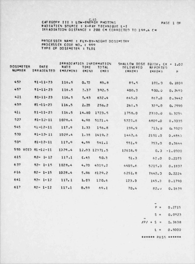
_ _ _ _ _ _ _ _
C.45C AT EGORY !!!' : LOW-ENERGY PHOTONS PAGE 1 0FR ADI ATICN SOURCE : X-R AY T ECHNI QU E L-IIRt ADIATION- DI STANCE : 200 CM CORRECTED TO 19R.4 CM
PROCE SSCR NAME : FLY-8Y-NIGHT 00 SIME TRYPROCES$ CR CODE NO. 990TYPE OF DOSIMETER : TLD1
| IRR ADI ATIOh INFORM ATION SHALLOW DOSE EQUIV, CX = 1.02DOSIMETER DATE R AT E TIME TO TAL DE L IVE RE D RF POC TEDNUMBER IRR ADI A TED (MR/ MIN) (MINI (MR) (MREMI (MREMI P
>
452 91-11-23 116.5 0. 72 83. 8 85.5 101.0 0. 1809
457 31-11-23 116.5 2.37 392.5 400.3 500.0 0. 2493i
421 81-11-23 116.5 !. 43 632.4 645.0 867.0 0.3442i'
430 81-11-23 116.5 2. 20 256.2 261.3 320.0 0.2590
j 411 81-11-23 116.5 14.60 1723.5 1758.0 2330.0 0.3254
| 522 81-12-11 1028.4 4.98 5121.4 5223.8 6809.0 0.3035
545 91-12-11 117.9 1.33 156.8 159.9 213.0 0.3320i
i 530 R 1-12- 11 1028.4 1.38 1419.2 1447.6 2151 .0 0.48631
) 505 81-12-11 117.9 4.59 541.1 551.9 753.0 0.3644<
j 550 VOIS 81-12-11 13 29.4 12.03 12371.5 12618.9 0. 0 -1.0000
615 82- 1- 12 117.1 C.43 50.3 51.3 62.0 0.2075
637 82- 1-15 1028.4 4.20 4319.2 4405.6 5215.0 0.1837.
616 82- 1-15 1028.4 5.96 6129.2 6251.8 7642.0 0.2224
641 R2- 1-12 117. 1 1.03 120.6 123.0 145.0 0.1790
617 82- 1-12 117.1 0.59 69.1 70.4 82.9 0.1639i
! -
P= 0.2715
S= 0.0923,
_
i /P/ + 5 0.3638=
i L= 0.5000|
| ****** PASS ******
!
i
_ _ _ _ . _ _ _ . _ _ __ __ _.. _ . . . _ _, _ _ . _ _ _ _ _ _ _ _ _ _ . _ _ _ _ _ ._
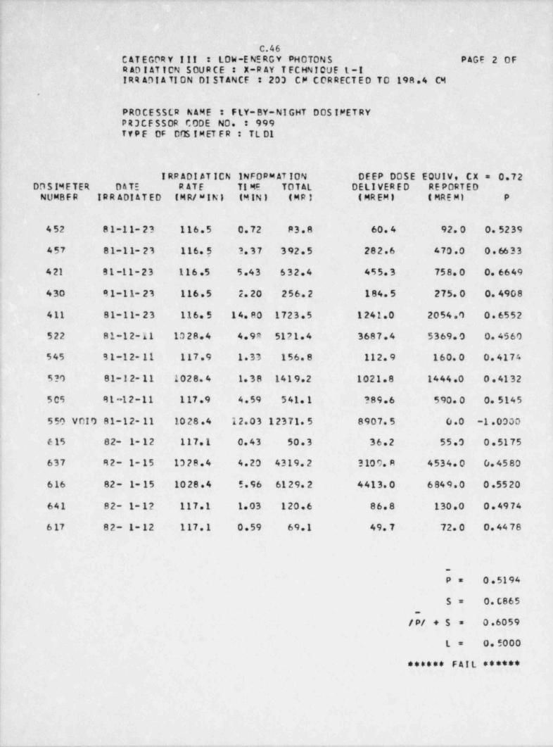
.
C.46C ATEGORY III : LOW-E NE RG Y PHOTON S PAGE-2 0FR AD I AT T CN SOUR CE : X-R AY T ECHNIQUE t-i'IRR ADI A TI ON DI ST ANCF : 203 CP CORRECTED TO 198.4 CM
.
PROCESSCR NAME : FLY-BY-NIGHT DOS IPETRYPR3CF SSOR CODE NO. : 999T Y P E OF 00S !M ET ER : TL D1
IRRADIATICN INFORM AT ION DEEP DOSE EQUIV, CX = 0.72DD S IM E TER DATE RATE TI ME TOTAL DELIVERED RE PORT ED
NUMBER. IRR ADI AT ED ( M R/ W I N ) (MIN) (MRI (MREM) ( MRE M) P
452 81-11-23 116.5 0.72 P3.8 60.4 92.0 0.5239
457 81-11-23 116.5 ?.37 392.5 282.6 470.0 0.6633
4 21 81-11-23 116.5 5.43 632.4 455.3 758.0 0.6649
j 430 91-11-23 116.5 2.20 256.2 184.5 275.0 0.4908
411 81-11-23 116.5 14.80 1723.5 1241.0 2054.0 0.6552
522 81-12-11 1028.4 4.9R 5121.4 3687.4 5369.0 0.45604
545 B 1-12- 11 117.9 1.33 156.8 112.9 160.0 0.4174
5?O 81-12-11 1028.4 1.38 1419.2 1021.8 1444.0 0.4132
505 91-12-11 117.9 4.59 541.1 ?89.6 590.0 0.5145
550 VOIO 81-12- 11 1028.4 12.03 12371.5 8907.5 0.0 -1.00001
'
615 82- 1-12 117.1 0.43 50.3 36.2 55.0 0.5175
637 R 2- 1- 15 1328.4 4.20 4319.2 310 0. R 4534 0 0.4580
616 82- 1- 15 1028.4 5.96 6129.2 4413.0 6849.0 0.5520
641 82- 1- 12 117.1 1.03 120.6 86.8 130.0 0.4974,
6 17 82- 1-12 117.1 0.59 69.1 49.7 72.0 0.4478
_
P= 0.5194
S= 0.C865|
-
0.6059| / P/ +5 =
L= 0.5000
****** FAIL ******
- _ _ - _ . _ _ _ _ _ . _ . - . . . - - _
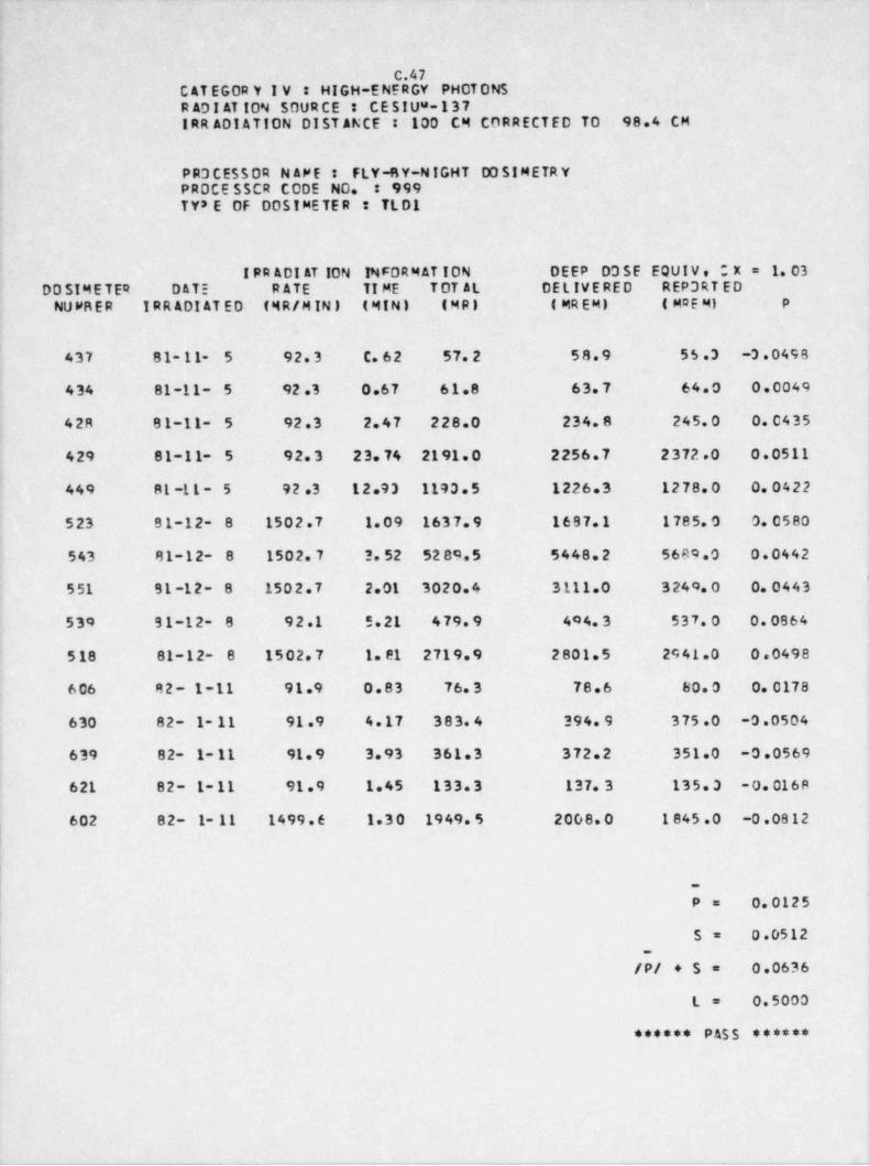
_- _ _ _
C.47C AT EGOR Y I V : HI GH-E NE R GY PHOT ONSR ADI AT ION SOURCE : CESIUS-137IRR ADI ATION DIST ANCE':' 100 CM CORRECTED TO 98.4 CM
PR3CE550R N AME : FLY-MY-NIGHT D3 SIMETRYPROCE SSCR CODE NO. : 999TY8 E OF 00SIMETER : TLD1
I PR ADI AT ION INFOR M AT I ON DEEP DDSE EQUIV, *X= 1.03
DD SIM E TER DATE RATE TI ME T OT AL DELIVERED REP 3RT ED
NUFRER IRR ADI AT ED (MR/ MIN) (MIN) (MR) ( MR EM) ( MQE M) P
437 81- 11- ~ 5 92.3 C.62 57.2 58.9 55.3 -3.0498
434 81-11- 5 92.3 0.67 61.8 63.7 64.0 0.0049
42R 81-11- 5 92.3 2.47 228.0 234.8 245.0 0.0435
429 81-11- 5 92.3 23.74 2191.0 2256.7 2372.0 0.0511
449 R1 -11 - 5 92.3 12.93 1193.5 1226.3 1278.0 0.0422
523 B1-12- 8 1502.7 1.09 1637.9 1697.1 1785.0 0.0580
543 81-12- 8 1502.7 3. 52 5289.5 5448.2 5689.0 0.0442'
551 91-12- 8 1502.7 2.01 3020.4 3111.0 3249.0 0.0443
539 91-12- 8 92.1 5.21 479.9 494.3 537.0 0.0864
518 81-12- 8 1502.7 1. 81 2719.9 2801.5 2941.0 0.0498
606 82- 1-11 91.9 0.83 76.3 78.6 80.0 0.0178
630 82- 1- 11 91.9 4.17 383.4 394.9 375.0 -0.0504
639 82- 1-11 91.9 3.93 361.3 372.2 351.0 -0.0569
621 82- 1-11 91.9 1.45 133.3 137.3 135.3 -0.0168
602 82- 1- 11 1499.6 1.30 1949.5 2008.0 1845.0 -0.0812j
l
!
"
0.0125P =
S= 0.0512.
/P/ +S= 0.0636
L= 0.5000
****** PASS ******
_ _ _ _ _ _ _ _ _ _ _ _ _ _ _ _ _ ,_
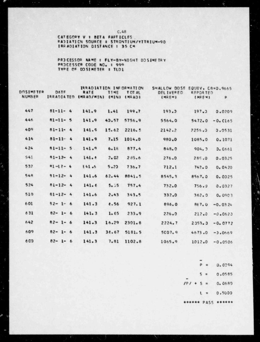
_. _ __ _ _ _ _ _ _ _ _ _ _ _ _ -
|
c.48C AT EGORY Y : BET A FAFT ICLES ,D A)I ATI CN SOURCE $7RONTIUM/ YTTRIUM-90IRR ADI ATION DIST ANCE : 35 CM
P R3 CESSOR NA ME : FLY-BY-NIGHT D3 SIME TR YPR3CESSCR CODE NO. 990TYPE OF D3SIMETER : TLD1
1%R AD14T 10N I NF ORM ATI ON SH AL LOW DO SE EQUIV, CB=0.9665DOSIMFTER DATF R AT E TIME T OT AL DELIVERED REPORTEDNUMBER IRR ADI A TED (MRAD / MIN) (MINI (MRADI (MRE45 (MRE4) P
447 81-11- 4 141.9 1.41 199.7 193.3 197.3 0.0209
446 81-11- 5 141.9 40.57 5756.9 5564.0 5472.0 - 0. C16 5
000 81-11- 4 141.9 15.62 2216.5 2142.2 2256.0 3.0531
414 81-11~ 4 141. 9 7.15 1014.0 980.0 1085.0 0. 1071
424 81-11- 5 141.0 6.1E 877.4 848.0 904.3 3.C661
$41 81-12- 4 141.6 2.02 285.6 276.0 28S.0 0.0325
532 91-12- 4 141.5 5.23 736.7 712.1 742.0 0.0420
54R 91-12- 4 141.6 62.44 8841.5 8545.3 8567.0 0.0025
524 81-12- 4 141.6 5. $ 5 757.4 732.0 756.0 0.0327
510 81-12- 4 141.6 2.43 343.5 332.0 362.0 0.0903
601 92- 1- 6 141.3 e.56 927.1 896.0 867.0 -0.03 24
631 82- 1- 6 141.3 1.65 233.9 226.0 212.0 -0.0620
642 82- 1- 6 141.3 16.29 2301.8 2224.7 2053.3 -0.0772
609 82- 1- 6 141.3 36.67 5181.5 5C07.9 4673.0 -3.0669
603 82- 1- 6 141.3 7.81 1102.8 1065.9 1012.0 -0.0506
_
P = 0.0094
5= 0.0585.
/P/ + 5 = 0.0680
L= 0.5000
...... ,,SS ...... I
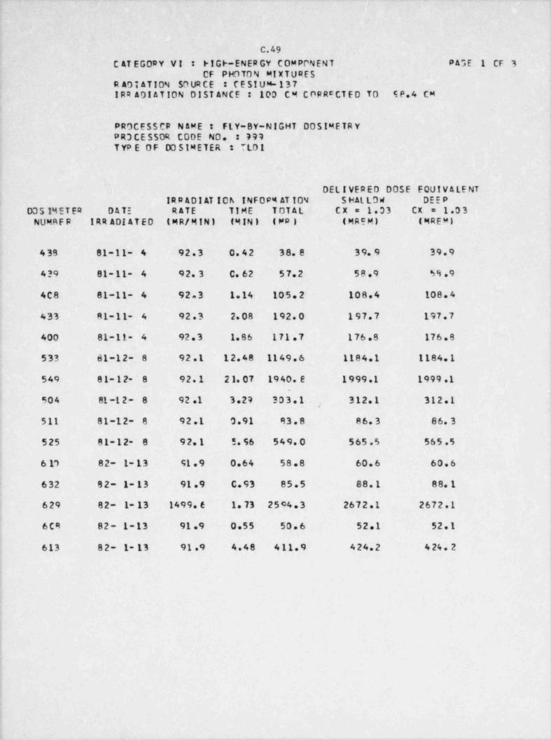
C.49
C AT EGORY VI : FIGF-ENER GY COMPPNENT PAGE 1 CF 3CF PHOTON MIXTURES ,
R ADI ATION SO UR CE : CESIUS-137IRR ADI ATION DIST ANCE : 100 C M C OR RC CT E D TO SP.4 CM
4
PROCESSCR N AME : FLY-8Y-NIGHT DOSIMETR YPR3 CE SSOR CODE NO. : 797TYP E OF DO SIMETER : TLDI
DELIVERED DOSE EQUIVALENTIRD ADI AT IOh INFDP4 AT ION S HAL LO W DEEP
D351M ET ER DATE RATE TIME TOTAL CX = 1.03 CX = 1.0 3NUMRFR 1RR ADI ATED ( M R/ M I N ) (M IN ) (MP) (MRCM) (MREMI
438 81-11- 4 92.3 0.42 38.8 39.9 39.9
439 81- 11- 4 92.3 C.62 57.2 58.9 59.9
4C8 81-11- 4 92.3 1.14 105.2 108.4 108.4
433 81-11- 4 92.3 2.08 192.0 197.7 197.7
400 81-11- 4 92.3 1.86 171.7 176.8 176.8
533 61-12- 8 92.1 12.48 1149.6 1184.1 1184.1
549 81-12- 8 92.1 21.07 1940.E 1999.1 1999.1
904 81 -1 2 - 8 92.1 3.27 303.1 312.1 312.1!
,
511 81-12- 8 92.1 0.91 83.8. 86.3 86.3
525 81-12 '8 92.1 5.96 549.0 565.5 565.5
6 17 82- 1-13 91 .9 0.64 58.8 60.6 60.6
632 82- 1- 13 91.9 C.93 85.5 88.1 88.1'
4
! 629 82- 1- 13 1499.6 1.73 25c4.3 2672.1 2672.1i
6CR 82- 1-13 91.9 0.55 50.6 52.1 52.1 |
613 82- 1- 13 91.9 4.48 411.9 424.2 4 24. 2
1
i
;
i
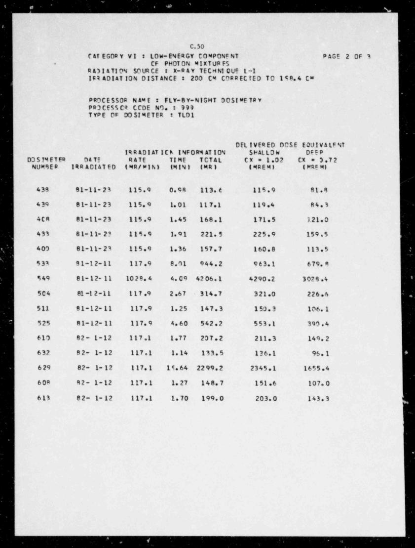
_. - . __ _ _ _ _ _ _ _ _ _ _ _ _ _ _ _ _ _
C.50
C AT EGOR Y VI : LOW-ENERGY COMPONE NT PAGE 2 0F 3CF PHOTON MIXTUR FS-
R A3 t ATION SO UR CE : X-R A Y TECH NI QUE L*IIRR ADI AT ION DIST ANCE : 203 CM CORR ECTED TO 198.4 CM
PROCESSOR N AM E : FLY-BY-NIGHT DOSI ME TR YPR3CESSCR CCDE NO. : 999TYPE OF DOSIMETER : TLD1
DEL IVER ED DOSE EQUIVALE NTIRR ADI AT ICh INFORM AT ION S HAL LO W DEEP
D3 51M ET ER D A TE RATE TI ME TOTAL CX = 1.02 CX = 3.72NUMBER IRR ADI AT ED ( MR/ WI h) (MIN) (MR) (MREMI ( MRE MI
439 81-11-23 115.9 0.98 113.6 115.9 81.8
439 81-11-23 115.o 1.01 117.1 119.4 84.3
4CR 81-11-23 115.9 1.45 168.1 171.5 121.0
433 81-11-23 115.9 1.91 221.5 225.9 159.5
409 81-11-23 115.9 1.36 157.7 160.8 113.5
533 81-12-11 117.9 8.01 944.2 963.1 679.8
549 81-12- 11 1028.4 4.09 4206.1 4290.2 3028.4
504 81-12-11 117.9 2.67 314.7 321.0 226.6
511 81-12-11 117.9 1.25 147.3 1 50. 3 106.1
525 81-12- 11 117.9 4.60 542.2 553.1 390.4
610 82- 1-12 117.1 1.77 207.2 211.3 149.2
632 82- 1-12 117.1 1.14 133.5 136.1 96.1
629 82- 1- 12 117.1 15.64 2299.2 2345.1 1655.4
60A R 2 - 1 - 12 1 17 . 1 1.27 148.7 151.6 107.0
613 82- 1- 12 117.1 1.70 199.0 203.0 143.3
7
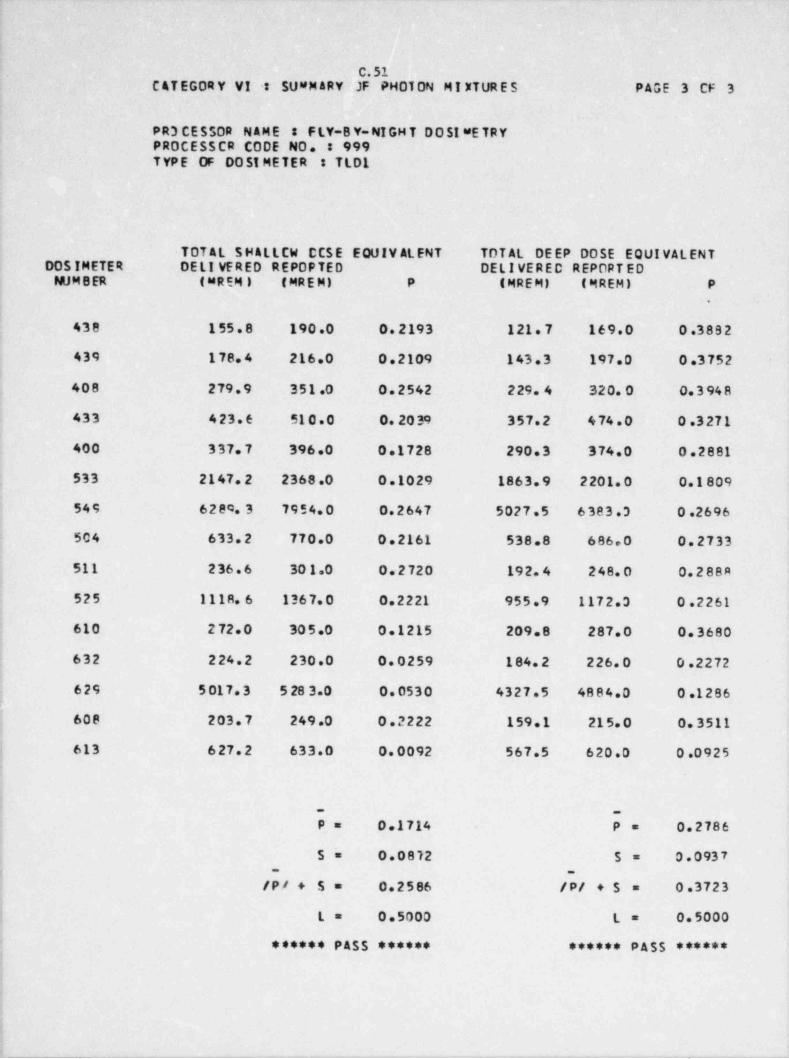
- _ _ _ _ _ _ _ . ._. . _ - -_.
C.51C ATEGORY VI s SU8M ARY JF PHOTON MI XTURES PAGE 3 CF 3
PR3 CE SSOR NAME : - F LY-8 Y-NI GH T D O SI #E TR YPROCES$CR CODE NO. : 9997 YP E OF 005IMETER TLOL
TOT AL SHALLCW CCSE EQUIV ALENT TOT AL DE EP DOSE EQUIVALENTDOSIMETER DELI VERED REPOPTED DELIVERED REPORTED
NUM B ER (MREMI ( MR E M) P (MREM) (MREM) P'
.
438 1 55.8 190.0 0.2193 121.7 169.0 0.3892
439 178.4 216.0 0.2109 143.3 197.0 0.3752
408 279.9 351.0 0.2542 229. 4 320.0 0.3948
433 423.6 51 0.0 - 0.2039 357.2 474.0 0.3271
400 337.7 396.0 0.1728 290.3 374.0 0.2881
: 533 2147.2 2368.0 0.1029 1863.9 2201.0 0.1809
! 549 6280.3 7954.0 0.2647 5027.5 6383.3 0.2696
504 633.2 770.0 0.2161 538.8 686.0 0.2733
511 236.6 30 1.0 0.2720 192.4 248.0 0.288A
525 1118.6 1367.0 0.2221 955.9 1172.3 0.2261a
610 2 72.0 305.0 0.1215 209.8 287.0 0.3680I
i 632 224.2 230.0 0.0259 184.2 226.0 0.2272i
629 5017.3 5283.0 0.0530 4327.5 4884.0 0.1286.
{ 608 203.7 249.0 0.2222 159.1 215.0 0.3511
| 613 627.2 633.0 0.0092. 567.5 620.0 0.0925i
ij _ _
P= 0.1714 P =*
0.2786
S= 0.0812 5= 0.0937,
-3
-
i /P/ + 5= 0.2586 /P/ +$ 0.3723=i
f L= 0.5000 L= 0.5000
; ...... ,S$ ...... ...... P 55 ......
;
4
I
_. . . . ___ _ . .- _- . _ __ .
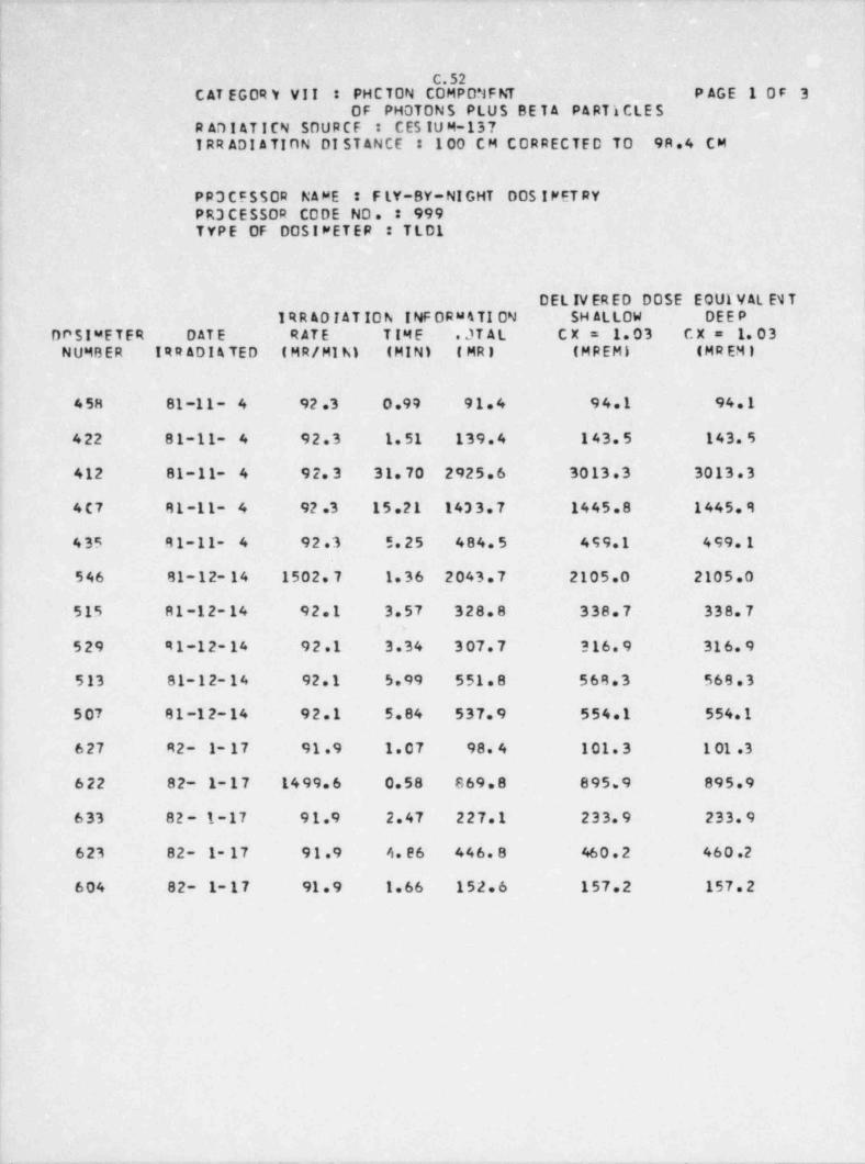
|
|
l C.52| CAT EGOR Y VII : PHCTON COMPONFNT P AGE 10F 3
0F PHOTONS PLUS BE T A P A RT I CLE S'
R ADI ATICN SOURCF : C ES IU M-137IRR ADI ATION DI ST ANCE : 100 CM CORRECTED TO 98.4 CM
PR3 CESSOR NAME : F LY-BY-NI GHT DOS ! PET RYPR3 CESSOR CODE NO. : 999TYPE OF 00SIWETER : TLD1
OEL IV ERED DOSE EQUI VAL E1T1RR AD TAT ION INF ORM4TI ON SH ALLOW DEEP 1
DPSIwETER D AT E RATE TIME .JTAL CX= 1.03 CX= 1.03NUMBER IRR ADI A TED ( MR/ MI N) (MIN) (MRI (MREMI (MR EM I
458 81-11- 4 92.3 0.99 91.4 94.1 94.1
422 81-11- 4 92.3 1.51 139.4 143.5 143.5
412 81-11- 4 92.3 31.70 2925.6 3013.3 3013.3
4C7 81-11- 4 92.3 15.21 1433.7 1445.8 1445.9
435 R1-11- 4 92.3 5.25 484.5 499.1 499.1
546 81-12- 14 1502.7 1.36 2043.7 2105.0 2105.0
515 R1-12-14 92.1 3.57 328.8 338.7 338.7,
.
529 91-12-14 92.1 3.34 307.7 316.9 316.9
513 81-12-14 92.1 5.99 551.8 568.3 568.3
507 81-12-14 92.1 5.84 537.9 554.1 554.1
627 92- 1- 17 91.9 1.07 98.4 101.3 1 01 .3
622 82- 1-17 1499.6 0.58 869.8 895.9 895.9
633 82 - 1-17 91.9 2.47 227.1 233.9 233.9,
623 82- 1- 17 91.9 4.26 446.8 46 0 . 2 460.2
604 82- 1- 17 91.9 1.66 152.6 157.2 157.2
i
_
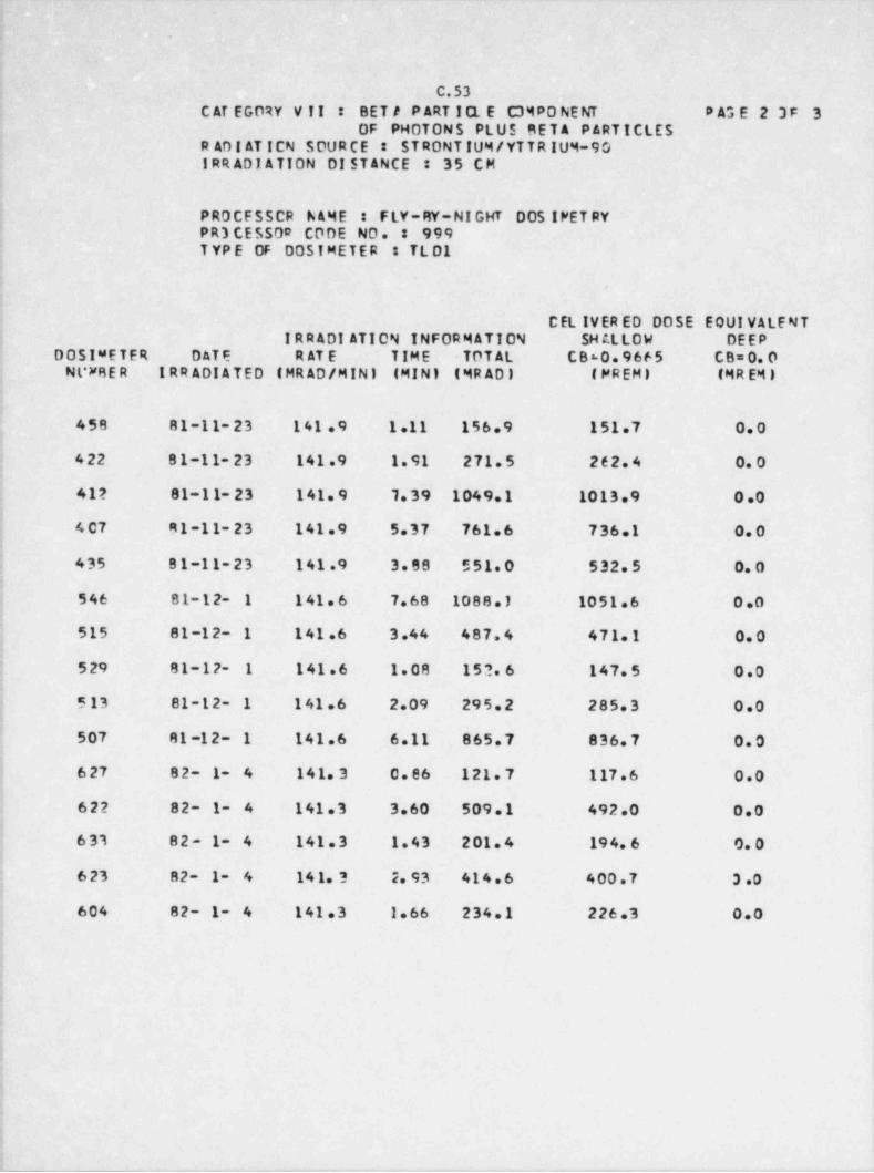
C.53C AT EGORY V II : BET A P ART I CL E . C3MPO NE NT # A3 E 2 3 F 3
0F PMOTONS PLUS . BET A P ARTICLESR AD I AT ICN SOUR C E ST RONT IUM / YT T R IUM-90IRR ADI ATION DI STANCE : 35 CM
PROCFSSCR hAME : F LY- RY- NI G HT DOS IFET RY'
PR3 CESS 00 CODE NO. * 999T YP E OF DOSIMETER TL D1
.
CEL IVER ED DOSE EQUIVALENTIRRADI ATION INFORMATION SH ALLOW DEEP
DOSIMETER DATE R AT E TIME TOTAL C860.9665 CB=0.0N L*FR E R IRR ADI ATED (MRAD / MIN) (MIN) (MRADI (FREMI (MR EM I
;
458 81-11-23 141 .9 1.11 156.9 151.7 0.0
422 81-11-23 141.9 1.91 271.5 262.4 0. 0;
41? 81-11- 23 141.9 1.39 1049.1 1013.9 0.01
4 07 91-11-23 141.9 5.37 761.6 736.1 0.0-
:
1 435 81-11-23 141.9 3.88 551.0 532.5 0. 0i
546 81-12- 1 141.6 7.68 1088.) 1051.6 0.0
515 81-12- 1 141.6 3.44 487.4 471.1 0.0
| 529 81-12- 1 141.6 1.08 152 6 147.5 0.0
5 13 81-12- 1 141.6 2.09 295.2 285.3 0.0
507 81 -12- 1 141.6 6.11 865.7 836.7 0.0
627 82- 1- 4 141.3 0.86 121.7 1 17 .6 0.0
622 82- 1- 4 141.3 3.60 509.1 492.0 0.0l'
6 33 82- 1- 4 141.3 1.43 201.4 194.6 0. 0
j 623 82- 1- 4 141.3 2.93 414.6 400.7 3 .0
604 82- 1- 4 141.3 1.66 234.1 226.3 0.0!
:1
!
:i
1
'!
- _ _ - _ _ _ . -- ._ -. .- _
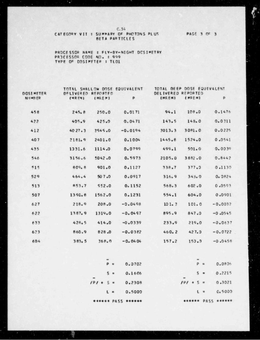
.. . . . ..
_
l
C.54C AT EGORY VII : SU MP ARY OF PHOTONS PLUS PAGE 3 Oc 3
8ET A PAR TICLE S
PROCE SSOR NAME I FLY-BY-NIGHT DCSIMET RYPR3CESSOR CODE NO. * 999TYPE Oc DOS!PFTEP TLO1
TOTAL SHALLOW DOSE EQUIVALENT TOTAL DE EP OOSE EQUIV ALENT0051 METER DSLIVERED REPORTFD DELIVERED REPORTED
Nil uB ER ( M R EM I (MREP) P (MREM) (PREM) P
458 245.8 250.0 0.0171 94.1 108.0 0.1476
422 405.9 425.0 0.0471 143.5 148.0 0.0311,
412 40 27.3 3S49.0 -0.0194 3013.3 3081.0 0.0225
407 2181.9 2401.0 0.1004 1445.8 1524.0 0.0541
435 1331.6 1114.0 0.0799 499.1 501.0 0.0030
546 3156.6 5042.0 0.5973 2105.0 3882.0 0.8442
515 809.8 901.0 0.1127 338.7 377.0 0.1130
529 464.4 50 7 .0 0.0917 316.9 343.0 0.0824
513 R53.7 552.0 0.1152 568.3 6 02 .0 0.0593
507 1390.8 1562.0 0.1231 554.1 604.0 0.0901
627 2 18. 9 208.0 -0.0498 10 1. 3 101.0 -0.0032
622 13 87. 9 1319.0 -0.0497 895.9 847.0 -0.0545
633 428.5 414.0 -0.0339 233.9 219.0 -0.0637
623 860.9 828.0 -0.03e2 460.2 427.0 -0.0722 ,
604 3 83. 5 368.0 - 0. 04 04 157.2 153.0 -0.0458
{
P= 0.0702 P= 0.0806
S= 0.1606 5= 0.2215_ _
/P/ + S= 0.2308 /P/ +5= 0.3021.
L= 0.5000 L= 0.5000
****** PASS ****** ****** PASS ******
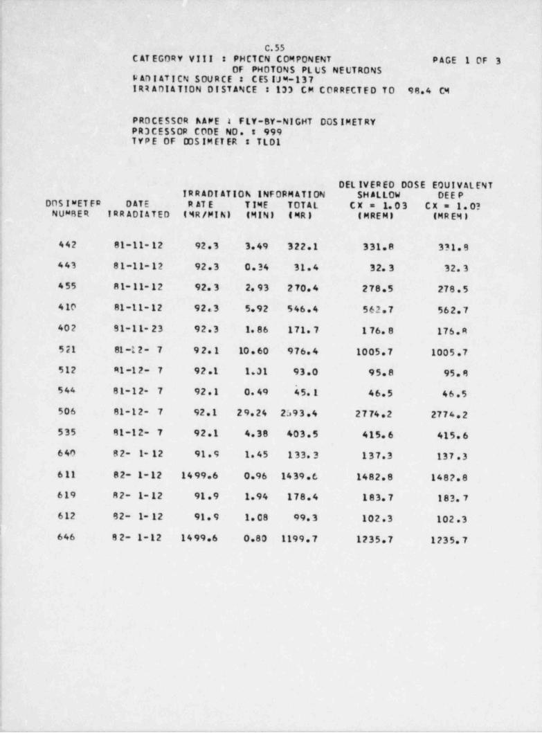
|
C.55C AT EGORY VIII : PHCTCN COMPONENT PAGE 1 0F 3
0F PHOTONS PL US NEUTRONSF AD I AT I CN SOU R CE : C ES IJ 4-137-
IRR ADI ATION DISTANCE : 133 CM CORRECTED TO 98.4 C4
PROCESSOR hAPE I F LY-8Y-N I GHT DOS IMET RYPR3 CESSOR CODE NO. 999TYPE OF 00S IM ET ER TLO1
DEL IVERED DOSE EQUIVALENTIRRADIATION INFORMATION SHALLOW DEE P
2
DOS!"ETER DATE R AT E T IME TOTAL CX= 1.03 CX = 1. 03NUMBER IRRADIATED (MR/ MINI (MIN) (MR) (MREMI (MR EM I
'
442 81-11- 12 92.3 3.49 322.1 331.8 3?1.9,
443 81-11-12 92.3 0.34 31.4 32.3 32.3
455 81-11-12 92.3 2.93 270.4 278.5 278.5 l;
4 10 81-11-12 92.3 5.92 546.4 562.7 562.7
402 91-11-23 92.3 1.86 171.7 1 76. 8 176.R
521 81 -1 2 - 7 92.1 10 . 60 976.4 1005.7 1005.7
512 M1-12- 7 92.1 1.31 93.0 95.8 95.8'
544 81-12- 7 92.1 0.49 45.1 46.5 46.5
506 81-12- 7 92.1 29.24 2593.4 2774.2 2774.2;'
535 81-12- 7 92.1 4.38 403.5 415.6 415.61640 82- 1- 12 91.9 1.45 133.3 137.3 137.3'
611 82- 1-12 1499.6 0.96 1439.6 1482.8 148?.8
619 82- 1- 12 91.9 1.94 178.4 183.7 183.7
I 612 92- 1- 12 91.9 1.08 99.3 102.3 102.3i' 646 82- 1-12 1499.6 0.80 1199.7 1235.7 1235.7
|
,
V
e
i
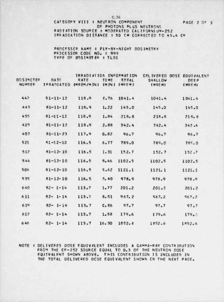
_ _ _ _ _ _ _ _ _ _ _ _ _ _ - _ _
I;
C.56C AT EGORY VIII : NEUT RON COMPONENT PAGE 2 05 3'
0F PHOTONS PLUS NEUTRONS| R AD I ATI ON SO UR C E MODER ATED CALIFORNI UM-252
IRR ADI ATION DISTANCE : 50 CM CORRECT ED TO 45.4 C4t
PROCFSSCR NAME : FLY-BY-NIGHT DOS IMETRYPR3CESSOR CODE NO. : 999TYPE OF DOS IM ET ER TLD1
IRR ADI ATIOh INFORM AT ION CEL IVER ED DOSE EQUIVALENTDO S IMETER DATE RATE TI ME TOTAL SHALLOW DEEPNUMBER I# RADIATED (MR EM /M IN ) (M IN 1 (MR EM I ( M RE M) ( MR E M)
l
44? S1-11- 12 118.9 f.76 1041 4 1041.4 1 041.4
443 81-11-12 118.9 1.22 145.0 145.0 145.0
455 81-11-12. 118.9 1.84 218.8 218.8 218.8
410 81-11- 12 118.9 2.88 342.4 342.4 342.4
402 81-11-23 117.9 0.82 96.7 96.7 96.7
521 41-12-10 116.5 6.77 789.0 789.0 78e, o
| 512 81-12- 10 1 16.5 1.31 152.7 152.7 152.7
544 81-12-10 116.5 9.46 1102.5 1102.5 1102.5
506 81-12-10 116.5 S.62 1121.1 1121.1 1121.1~
535 81-12-10 116.5 5.40 978.9 978.9 978.0
640 82- 1-14 113.7 1.77 201.2 201.2 201.2
6 11 82- 1- 14 113.7 8.51 967.2 967.2 467.2,
|
610 82- 1- 14 113.7 C. 86 97.7 97.7 97.7
612 82- 1-14 113.7 1.'58 179.6 179.6 179.5
6 46 82- 1- 14 113.7 16. 30 1852.6 1852.6 1R52.6|
NOTE : DELIVERED DOSE EQUIV ALENT INCLUDES A G AMM A-R AY CONTR IBUTIONFROM THE CF-252 SOURCE ECUAL TO 0.3 0F THE NEUTRON DOS EEQ'JIV ALENT SHOWN A20VE. T HIS CONTRIBUTION I S INCLUDED INTHE TOTAL DELIVERED DCSE EQUIVALENT SHOWN CN THE NEXT P AGE.
_________ -_ -
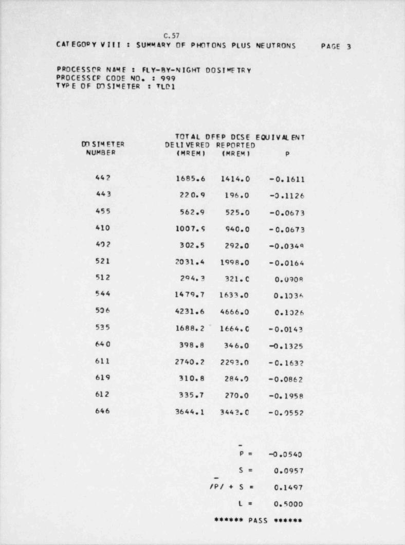
!
I1
C.57C AT EG09 Y V I! ! : SUMM ARY OF PHOTONS PLUS NEUTRONS PAGE 3
PROCESSOR N AM E : FLY-BY-N IGHT 00 SI ME TR YPROCESS CF CODE NO. : 999TYP E OF D1 SIMETER : TLD1
TOT AL DFEP DCSE EQUIV AL ENTD3 SIM ET ER DE LI VE RED REPORTEDNUMBER (MREM) (MREM) P
442 1685.6 1414.0 -0.1611
443 220.9 196.0 -0.1126
455 562.9 525.0 -0.0673
410 1007.5 940.0 - 0.0673
402 3 02.5 292.0 -0.0344
521 2031.4 1998.0 -0.0164
512 204.3 321.C 0.0908
544 1479.7 1633.0 0.1336
506 4231.6 4666.0 0.1326
535 1688.2 ~ 1664.C -0.0143
640 398.8 346.0 -0.1325
611 2740.2 2293.0 - 0.163?
619 310.8 284.0 -0.0862
61 2 335.7 270.0 -0.1958(i 646 3644.1 3443.0 -0.0552
~
1P= -0.0540 i
S= 0.0957_
/P/ + 5 = 0.1497
L= 0.5000
****** PASS ******
._____ _ _ _ _ _ _ _ _ - _ - - . _ - __ . - _ _ _ _ _ _
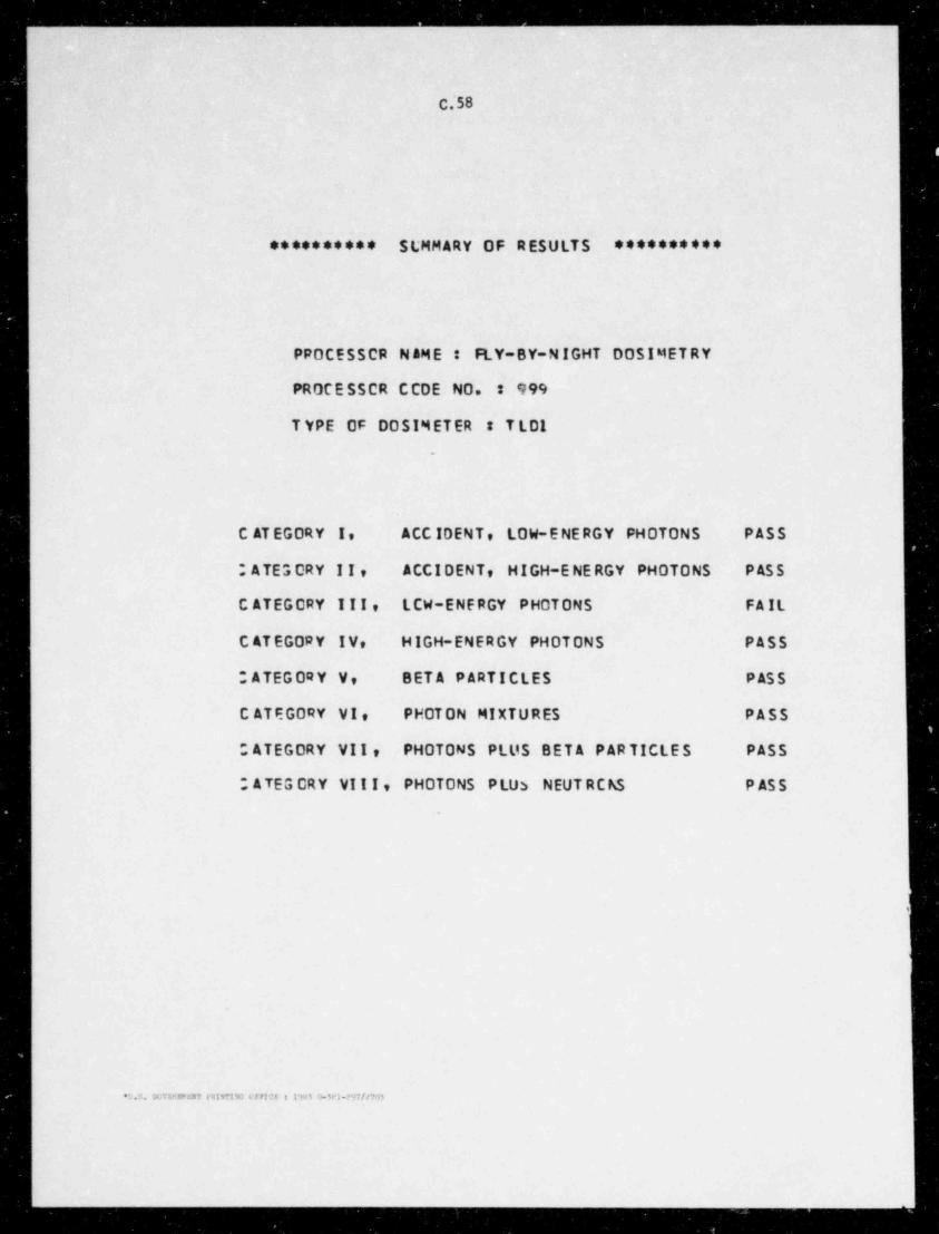
_____ . . _ .. . _ _ _ _ _ _ _ _ _ _ _ _ _ _ _ _ _ _
C.'58
(
********** SLMMARY OF RESULTS **********
PROCESSCR N AME : FLY-BY-NIGHT DOSIMET RY
PROCE SSCR CCOE NO. : 999
T YPE OF DOSIMETER T LOI.
C AT EGORY I, ACC IDENT, LOW-ENERGY PHOTONS PASS
; ATE 3 CRY II, ACCIDENT, HIGH-ENERGY PHOTONS P AS S
C ATEGORY III, LCW-ENERGY PHOTONS FAIL
C ATEGORY I V, HIGH-ENERGY PHOTONS PASS
OATEGORY V, BETA PARTICLES P AS S
C ATEGORY VI, PHOTON MIXTURES PASS
OATEGORY VII, PHOTONS PLUS BETA PARTICLES PASS
; ATEG CRY VIII, PHOTONS PLU3 NEUT RC h5 P AS S
,
'J.S. GUTERNWENT FRIMTING OFFION t l'*5$1 tb3P).??7//703
C_ _ . . _ _ . .. . . . _ _ m
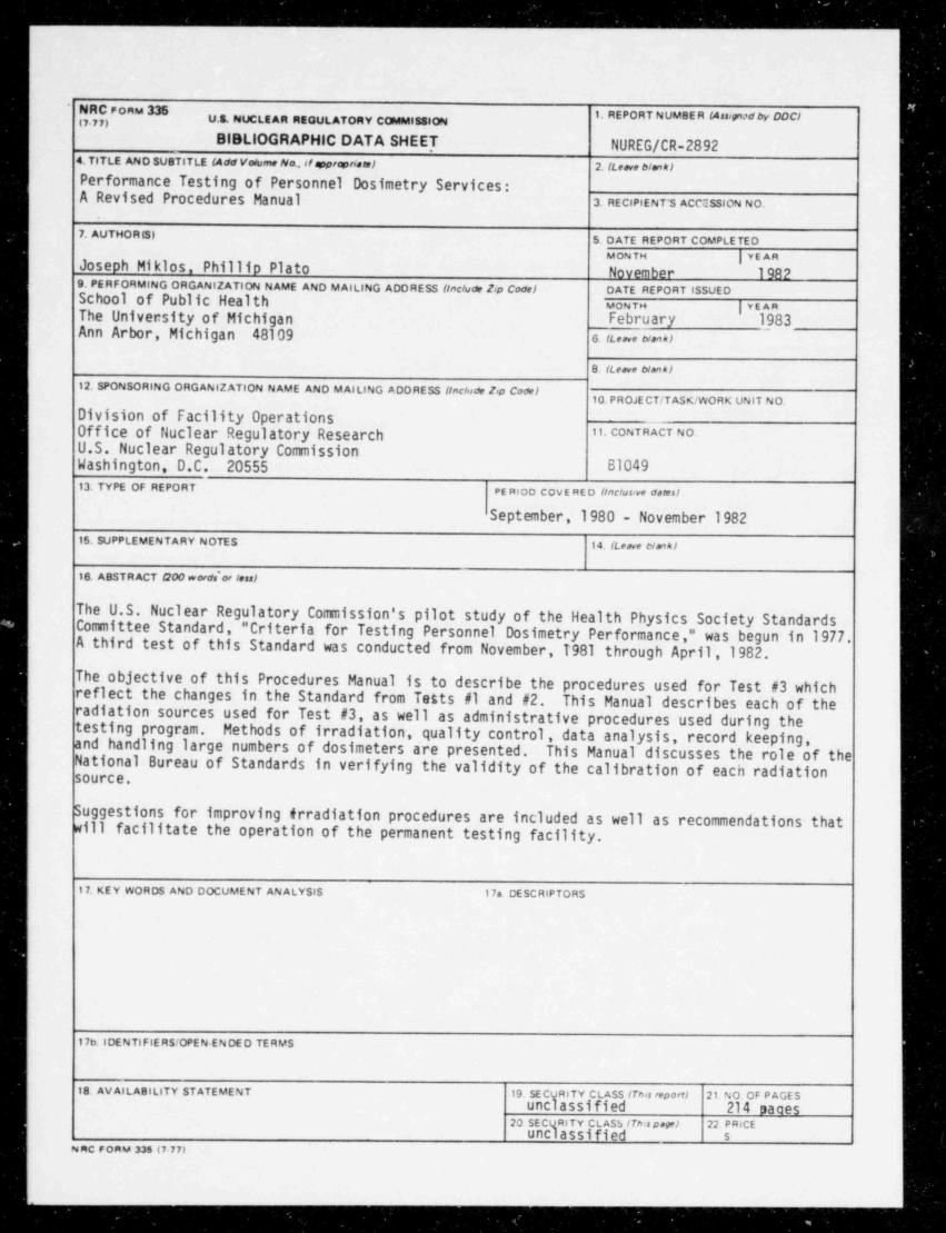
_ _ _ _
PORM M(7 77) U.S. NUCLEAR REOULATORY COMMISSION
BIBLIOGRAPHIC DATA SHEET NUREG/CR-28921 TlTLE AND SUOTITLE (Add Vodume Na, if espreriam1 2. (Leave blek/
Performance Testing of Personnel Dosimetry Services:A Revised Procedures Manual 3. RECIPIENT'S ACCESSION NO.
7. AUTHOR (S) 5. DATE REPORT COMPLETEDM ON TH | YEARJoseph Miklos, Phillip Plato November 1982
9. PERFORMING ORGANIZATION NAME AND MAILING ADDRESS (include t<p Code / DATE REPORT ISSUEDSchool of Public Health MONra |vEARThe University of Michigan February 1983Ann Arbor, Michigan 48109 s.(t.,ve Nen*>
8. (Leave Nanki
12. SPONSORING ORGANIZATION NAME AND MAILING ADDRESS (tachide 2,p Codel10. PROJECT / TASK / WORK UNIT NO.
I Division of Facility OperationsOffice of Nuclear Regulatory Research M. C NTRACT NO.
U.S. Nuclear Regulatory CommissionWashington, D.C. 20555 B104913. TYPE OF REPORT PE RIOD COVE RED (inclusive dses)
September,1980 - November 1982
15. CUPPLEMENTARY NOTES . 14. (Leave Nmkl
16. ABSTRACT 000 words'or less)|
The U.S. Nuclear Regulatory Commission's pilot study of the Health Physics Society StandardsCommittee Standard, " Criteria for Testing Personnel Dosimetry Performance," was begun in 1977.A third test of this Standard was conducted from November,1981 through April,1982.
The objective of this Procedures Manual is to describe the procedures used for Test #3 whichreflect the changes in the Standard from Tetts #1 and #2. This Manual describes each of theradiation sources used for Test #3, as well as administrative procedures used during thetesting program. Methods of irradiation, quality control, data analysis, record keeping,and handling large numbers of dosimeters are presented. This Manual discusses the role of theNational Bureau of Standards in verifying the validity of the calibration of each radiationsource.
Suggestions for improving irradiation procedures are included as well as recommendations thatwill facilitate the operation of the permanent testing facility.
17. KEY WORDS AND DOCUMENT ANALYSIS 17a. DESCRIPTORS
17b. IDENTIFIE RS/OPEN-ENDED TERMS
18. AVAILABILITY STATEMENT 19. SECURITY CLASS (Thss reporff 21. NO. OF P AGESunclassified 214 saaes
20. SECURITY CLASS (This papel 22. PRICEunclassified s
NRCFORM 336 (7 77)
-_ _ _ _ _ _

UNITED STATES ,ouarn class zait
NUCLEAR REGULATORY COMMISSION '05''',E,('"$ '''Og
WASHINGTON, D.C 20556 wasa o ePE RMIT to M
OFFICIAL BUSINESSPENALTY FOR PRIVAff USE $3X)
,
..
-r_
Related Documents