778 Journal of Mechanical Science and Technology {KSME Int J), Vol 19. No 3, pp 778-791, 2005 Performance Improvement of Pneumatic Artificial Muscle Manipulators Using Magneto-Rheological Brake Kyoung Kwan Ahn* School of Mechanical and Automotive Engineering, University of Ulsan, San 29, Muger Idong, Nam-gu, Ulsan 680- 764, Korea TU Diep Cong Thanh Graduate School of Mechanical and Automotive Engineering, University of Ulsan, San 29, Muger 2dong, Nam-gu, Ulsan 680- 764, Korea Young Kong Ahn Research Center for Machine Parts and Material Processing, University of Ulsan, San 29, Muger 2dong, Nam-gu, Ulsan 680-764, Korea A novel pneumatic artificial muscle actuator (PAM actuator), which has achieved increased popularity to provide the advantages such as high strengtJi and high power/weight ratio, low cost, compactness, ease of maintenance, cleanliness, readily available and cheap power source, inherent safety and mobility assistance to humans performing tasks, has been regarded during the recent decades as an interesting alternative to hydraulic and electric actuators However, some limitations still exist, such as the air compressibility and the lack of damping ability of the actuator bring the dynamic delay of the pressure response and cause the oscillatory motion Then it is not easy to realize the performance of transient response of pneumatic artificial muscle manipulator (PAM manipulator) due to the changes in the external inertia load with high speed In order to realize satisfactory control performance, a variable damper — Magneto- Rheological Brake (MRB), is equipped to the joint of the manipulator Superb mixture of conventional PID controller and a phase plane switching control method brings us a novel controller This proposed controller is appropriate for a kind of plants with nonhnearity, unceitamties and disturbances. The experiments were carried out in practical PAM manipulator and the effectiveness of the proposed control algorithm was demonstrated through experiments, which had proved that the stability of the manipulator can be improved greatly m a high gain control by using MRB with phase plane switching control method and without regard for the changes of external inertia loads Key Words : Pneumatic artificial muscle, Magneto-Rheological brake, Phase plane switching control, Manipulator wer sources electric motors, hydraulic cylinders 1. Introduction and pneumatic cylinders Each of these actuation systems has advantages and disadvantages (Table Industrial robots have used three primary po- l) For most robotic applications, the common ' Coiresponding Author, actuator technology is electric system with very E-mail kkanh@ulf,an ac kr limited use of hydraulics Or pneumatics But elec- trical systems suffer from relatively low power/ TEL +82-52-222-1404, FAX +82-52-259-1680 School of MeohaniCiil and Automotive Engineering, Vmvemty of Ulsan, San 29, Muger 26ong, Nam-gu, ^^'S^t ratio and especially in the case of human Ulsan 680-764, Korea (Manuscript Received July 22, friendly robot, or human coexisting and coUa- 2004. Revised January 24, 2005J borative Systems such as a medical and welfare Copyright (C) 2005 NuriMedia Co., Ltd.

Welcome message from author
This document is posted to help you gain knowledge. Please leave a comment to let me know what you think about it! Share it to your friends and learn new things together.
Transcript
778 Journal of Mechanical Science and Technology {KSME Int J), Vol 19. No 3, pp 778-791, 2005
Performance Improvement of Pneumatic Artificial Muscle Manipulators Using Magneto-Rheological Brake
Kyoung Kwan Ahn*
School of Mechanical and Automotive Engineering, University of Ulsan,
San 29, Muger Idong, Nam-gu, Ulsan 680- 764, Korea
TU Diep Cong Thanh
Graduate School of Mechanical and Automotive Engineering, University of Ulsan,
San 29, Muger 2dong, Nam-gu, Ulsan 680- 764, Korea
Young Kong Ahn
Research Center for Machine Parts and Material Processing, University of Ulsan,
San 29, Muger 2dong, Nam-gu, Ulsan 680-764, Korea
A novel pneumatic artificial muscle actuator (PAM actuator), which has achieved increased
popularity to provide the advantages such as high strengtJi and high power/weight ratio, low
cost, compactness, ease of maintenance, cleanliness, readily available and cheap power source,
inherent safety and mobility assistance to humans performing tasks, has been regarded during
the recent decades as an interesting alternative to hydraulic and electric actuators However,
some limitations still exist, such as the air compressibility and the lack of damping ability of the
actuator bring the dynamic delay of the pressure response and cause the oscillatory motion
Then it is not easy to realize the performance of transient response of pneumatic artificial muscle
manipulator (PAM manipulator) due to the changes in the external inertia load with high
speed In order to realize satisfactory control performance, a variable damper — Magneto-
Rheological Brake (MRB), is equipped to the joint of the manipulator Superb mixture of
conventional PID controller and a phase plane switching control method brings us a novel
controller This proposed controller is appropriate for a kind of plants with nonhnearity,
unceitamties and disturbances. The experiments were carried out in practical PAM manipulator
and the effectiveness of the proposed control algorithm was demonstrated through experiments,
which had proved that the stability of the manipulator can be improved greatly m a high gain
control by using MRB with phase plane switching control method and without regard for the
changes of external inertia loads
Key Words: Pneumatic artificial muscle, Magneto-Rheological brake, Phase plane switching control, Manipulator
wer sources electric motors, hydraulic cylinders
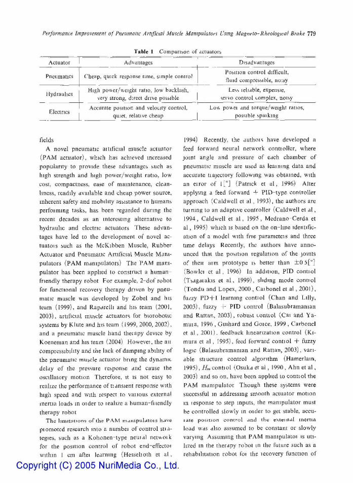
1. I n t r o d u c t i o n and pneumatic cylinders Each of these actuation
systems has advantages and disadvantages (Table Industrial robots have used three primary po- l) For most robotic applications, the common
' Coiresponding Author, actuator technology is electric system with very E-mail kkanh@ulf,an ac kr limited use of hydraulics Or pneumatics But elec
trical systems suffer from relatively low power/ TEL +82-52-222-1404, FAX +82-52-259-1680 School of MeohaniCiil and Automotive Engineering, Vmvemty of Ulsan, San 29, Muger 26ong, Nam-gu, ^^'S^t ratio and especially in the case of human Ulsan 680-764, Korea (Manuscript Received July 22, friendly robot, or human coexisting and coUa-2004. Revised January 24, 2005J borative Systems such as a medical and welfare
Copyright (C) 2005 NuriMedia Co., Ltd.
Performance Improvement of Pneumatic Arttfiaal Mwscle Manipulators Using Magneto-Rheologica! Brake 779
Actuator
Pneumatics
Hydraulics
Electrics
Table 1 Comparison of actuators
Advantages
Cheap, quick response time, simple control
High power/v^eight ratio, low backlash, very strong, direct drive possible
Accurate position and velocity control, quiet, relative cheap
Disadvantages
Position control difficult, Huid compressible, noisy
Less reliable, expensie, seivo control complex, noisy
Low po\\ei and torque/weight ratios, possible spaiking
fields
A novel pneumatic attificial muscle actuator
(PAM actuator), which has achieved increased
popularity to provide these advantages such as
high strength and high power/weight ratio, low
cost, compactness, ease of maintenance, clean
liness, readily dvailable and cheap power source,
inherent safety and mobility assistance to humans
perfoimmg tasks, has been regarded during the
recent decades as an interesting alternative to
hydraulic and electric actuators These advan
tages have led to the development of novel ac
tuators such as the McKibben Muscle, Rubber
Actuator and Pneumatic Artiftcial Muscle Mani
pulators (PAM manipulators) The PAM mani
pulator has been applied to construct a human-
friendly therapy robot For example, 2-dof robot
for functional recoveiy therapy driven by pneu
matic muscle was developed by Zobel and his
team (1999), and Raparelli and his team (2001,
2003), artificial snuscle actuators for biorobotic
systems by Klute and his team (1999, 2000, 2002),
and a pneumatic muscle hand theiapy device by
Koeneman and his team (2004) Howevei, the ait
compressibility and the lack of damping ability of
the pneumatic muscle actuator bring the dynamic
delay of the pressure response and cause the
oscillatory tnotion Therefore, it is not easy to
realize the performance of tiansient response with
high speed and with respect to vaiious external
inertia loads m oider to tealize a human-fiiendly
therapy robot
The limitations of the PAM manipula to is hdve
ptomotcd research into a numbei of control stia-
tegies, such as a Kohonen-lype neuial netwoik
for the position control of robot end-effectoi
within 1 cm aftei learning (Hessehoth et a l ,
Copyright (C) 2005 NuriMedia Co., Ltd.
1994) Recently, the authois have developed a
feed forward neural network conttolier, where
joint angle and pressure of each chamber of
pneumatic muscle arc used as learning data and
accurate trajectory following was obtained, with
an eiror of l[°] (Patrick et a l , 1996) Alter
applying a feed forward + PlD-type controller
approach (Caldwell et al , 1993), the authors are
turning to an adaptive controller (Caldwell et a l ,
1994, Caldwell et a l , 1995, Mcdrano-Cerda et
a l , 1995) which is based on the on-lme identific
ation of a model with five parameteis and three
time delays Recently, the authors have anno
unced that the position regulation of the joints
of then aim prototype is better than ± 0 5[°]
(Bowlci et a l , 1996) In addition, PID contiol
(Tsagaiakis et a l , 1999), slidmg mode contiol
(Tondu and Lopex, 2000, Caibonel et a l , 2001),
fuzzy PD + I learning contiol (Chan and Lilly,
2003), fuzzy + PID control (Balasubramanian
and Rattan, 2003), vobust tontiol (Cai antl Ya-
muia, 1996 , Guihard and Goice, 1999 , Carbonel
et a l , 2001). feedback linearization control (Ki-
mura et al , 1995), feed forward contiol + fuzzy
logic (Balasubramanian and Rattan, 2003), vari
able stiucture control algorithm (Hamerlatn,
1995), /f„ contiol (Osuka et a l , 1990, Ahn et a l ,
2003) and so on, have been applied to contiol the
PAM manipulator Though these systems were
successful m addressing smooth actuator motion
m lesponse to step inputs, the manipulator must
be controlled slowly in older to get stable, accu
rate position control And ihc extein^il inertia
load was also assumed to be constant or slowly
varying Assuming that PAM manspulatoi is uti
lized in the therapy robot in the future such as a
rehabilitation robot foi the iccovcry function of
780 Kyoung Kwan Ahn, TU Diep Cong Thanh and Young Kong Ahn
limbs, which is the final goal of this research, it is
necessary to realize a fast response, even if the
external inertia load changes severely But fast
response cannot be obtained in most pneumatic
control systems At the same time, the external
inertia loads cannot always be known exactly
Therefore, it is necessary to propose a new control
algorithm, which is applicable to a veiy com
pressible pneumatic muscle system with various
loads
Many new control algorithms based on a
neural network have been proposed up to now
An intelligent control using a neuro-fuzzy net
work was proposed by Iskarous and Kawamura
(1995) A hybrid network that combines fuzzy
and neural network was used to model and con-
trot complex dynamic systems, such as the PAM
system An adaptive controller based on the
neural network was applied to the artificial hand,
which is composed of the PAM {Folgheraiter et
a l , 2003) Here, the neural network was used as
a controller, which had the form of a compensator
or the inverse of the model It was not easy to
apply these control algorithms to the quickly-
changing inertia load systems and to reconcile
both damping and response speed in high gam
control
To overcome these problems, a new technology,
Electro-Rheological Fluid Damper (ER Dam
per) , has been applied to the PAM manipulator
Noritsugu and his team has used ER damper to
improve the control performance of the PAM
manipulator with PI controller and pulse code
modulated on-off valves (Noritsugu et a l , 1997 ,
J 999) By separating the region where the damper
produces an damping torque in order to reconcile
both the damping and the response speed m high
gain control, the results show that ER damper is
one of the most effective methods to develop a
piactically available human friendly robot by
using the PAM manipulator and also the per
formance of position control is improved without
decreasing the response speed However, some
limitations still exist, because ER Fluid (ERF)
requiies extremely high control voltage (kV),
which IS problematical and potentially dangerous,
and It has a narrow operation range of tempera
ture which can not be applied to the PAM mani
pulator, and has also the characteristics of non-
lineanty Because of the unacceptable disad
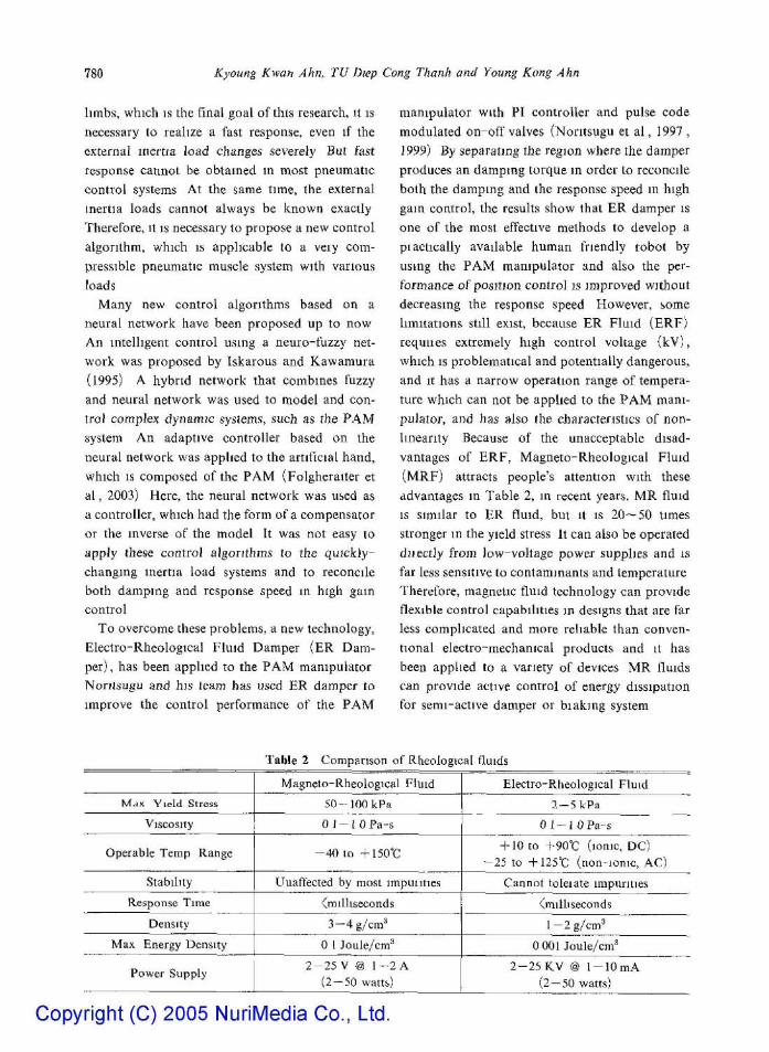
vantages of ERF, Magneto-Rheological Fluid
( M R F ) attracts people's attention with these
advantages in Table 2, in recent years. MR fluid
IS similar to ER fluid, but it is 20—50 times
stronger m the yield stress It can also be operated
diiectly from )ow-voltage power supplies and is
far less sensitive to contaminants and temperature
Therefore, magnetic fluid technology can provide
flexible control capabilities in designs that are far
less complicated and more reliable than conven
tional electro-mechanical products and it has
been applied to a variety of devices MR fluids
can provide active control of energy dissipation
for semi-active damper or biaking system
Table 2 Comparison of Rheological fluids
Mdx Yield Stress
Viscosity
Operable Temp Range
Stability
Response Time
Density
Max Energy Density
Power Supply
Magneto-Rheologicttl Fluid
SO--100kPa
Ql-{ OPa-s
- 4 0 to -t-150°C
Unaffected by most impuuties
^milliseconds
3 —4g/cm^
0 1 Joule/cm^*
2 - 2 5 V @ 1 -2 A
( 2 - 5 0 watts)
Electro-Rheological Fluid
2 - 5 kPa
0 1 - i OPa-s
-1-10 to +90°C (ionic, DC)
- 2 5 to -|-12S°C (non-ionic, AC)
Cannot toleiate impurities
(milliseconds
1 - 2 g/cm^
0 001 Joule/cm^
2 - 2 5 KV @ 1 - l O m A
( 2 - 5 0 watts)
Copyright (C) 2005 NuriMedia Co., Ltd.
Performance Iniprovemenl of Pneumalk Artificial Muscle Manipulators UsiFig Magneto-Rheologkii! Brake 781
Thus, the goal of this paper is to implement a
magneto-rlieological brake, to develop a fast,
accurate pneumatic control system and without
regard to the changes of exleriial inertia loads.
SLipcrb mixture of conventional PiD controller
and a phase plane switching control method bring
us a novel controller. This proposed controller is
appropriate for a kind of plants with nonlinearity
uncertainties and disturbances. The experiments
were carried out in practical PAM manipulator
and the effectiveness of Ihe proposed control
algoritlim was demonstrated through experiments,
which had proved that the stability of the mani
pulator can be well improved in a high gain
control by using MRB with phase plane switching
control method and without decreasing the re
sponse speed and low stiffness of manipulator.
2. Experimental Setup
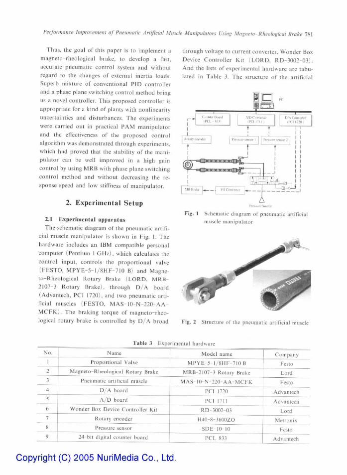
2.1 Experimental apparatus
The schematic diagram of the pneumatic artifi
cial muscle manipulator is shown in Fig. I. The
hardware includes an IBM compatible personal
computer (Pentium 1 GHz), which calculates the
control input, controls the proportional valve
(FESTO. MPYE-5-1/8HF-7IO B) and Magne-
to-Rheological Rotary Brake (LORD, MRB-
2107-3 Rotary Brake), through D / A board
(Advantech, PCJ 1720), and two pneumatic arti
ficial muscles (FESTO, MAS-10-N-220-AA-
MCFK). The braking torque of magneto-rheo-
logical rotary brake is controlled by D / A broad
through voltage to current converter. Wonder Box
Device Controller Kit (LORD. RD-3002-03).
And the lists of experimental hardware are tabu
lated in Table 3. The structure of the artiTicial
Pirssiirr Simrrc
Fig. I Schematic diagram of pneumatic artificial nuiscic manipulator
Fig. 2 Structure of the pneumatic artificial muscle
No.
1
2
3
4
5
6
7
8
9
Table 3 Experimental hardware
Name
Proportional Valve
Magneto-Rheologjcal Rotary Brake
Pneumatic artificial muscle
D / A board
A / D board
Wonder Box Device Controller Kit
Rotary encoder
Pressure sensor
24-bit digital counter board
Model name
MPYE-S- l /SHF-y iOB
MRB-2107-3 Rotary Brake
MAS-lO-N-220-AA-MCFK
PCI 1720
PCI 1711
RD-3002-0.1
H40-8-3600ZO
SDE-10-10
PCL 833
Company
Festo
Lord
Festo
Advantech
Advantech
Lord
Metronix
Festo
Advantech
Copyright (C) 2005 NuriMedia Co., Ltd.
782 Kyoiing Kwan Aim, TU Diep Cong Thanh and Young Kong Ahn
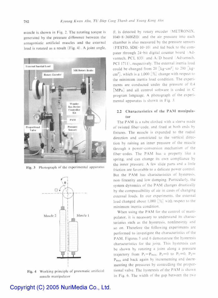
muscle is shown in Fig. 2. The rotuting torque is
genertited by Ihe pressure difference beiwcen the
antagonistic lirlificiiil muscles and the external
load is rotated as a result (Fig. 4). A joint angle.
Fig. 3 Photograph of the expcnmeniLiI apparatus
Muse JVluscle [
Fig. 4 Working principle of pneumatic artil'icial muscle mtmipulaair
d. is detected by rotary encoder : M E T R 0 N I X .
H40-8-3600ZOi and the air pressure into each
chamber is also measured by the pressure sensors
i.FESTO. SDE-10-lOi and fed back lo the com
puter through 24-bit digital counter board Ad-
vantech. PCL 833) and A/D board Advantech.
PCI 1711), respectively. The external inertia load
could be changed from 20 [kg-cm^J to 200 _kg*
cni^J, which is a 1.000 {%} change with respect to
the minimum inertia load condition. The experi
ments are conducted under the pressure of 0.4
[MPa] and ail control software is coded in C
program language. A photograph of the experi
mental apparatus is shown in Fig. 3.
2.2 Characteristics of the PAM manipuJa-
tor The PAM is a tube clothed with a sleeve made
of twisted fiber-code, and fixed at both ends by
fixtures. The muscle is expanded to the radial
direction and constricted to the \erticat direc
tion by raising an inner pressure of the muscle
through a power-conversion mechanism of the
fiber-codes. The P.AM has a property like a
spring, and can change its own compliance by
the inner pressure. A few slide pans and a linle
friction are favorable to a delicate power control.
But the PAM has characteristics of hysteresis,
non-linearity and low damping. Panicularh. the
system dynamics of the PAM changes drastically
by the compressibility of air in cases of changing
external loads. In our experiments, the external
load changed about 1.000 [%] with respect to the
minimum inertia condition.
When using the PAM for the control of mani
pulator, it is necessary to understand its charac
teristics such as the hysteresis, noniinearity and
so on. Therefore the following experiments are
performed to investigate the characteristics of the
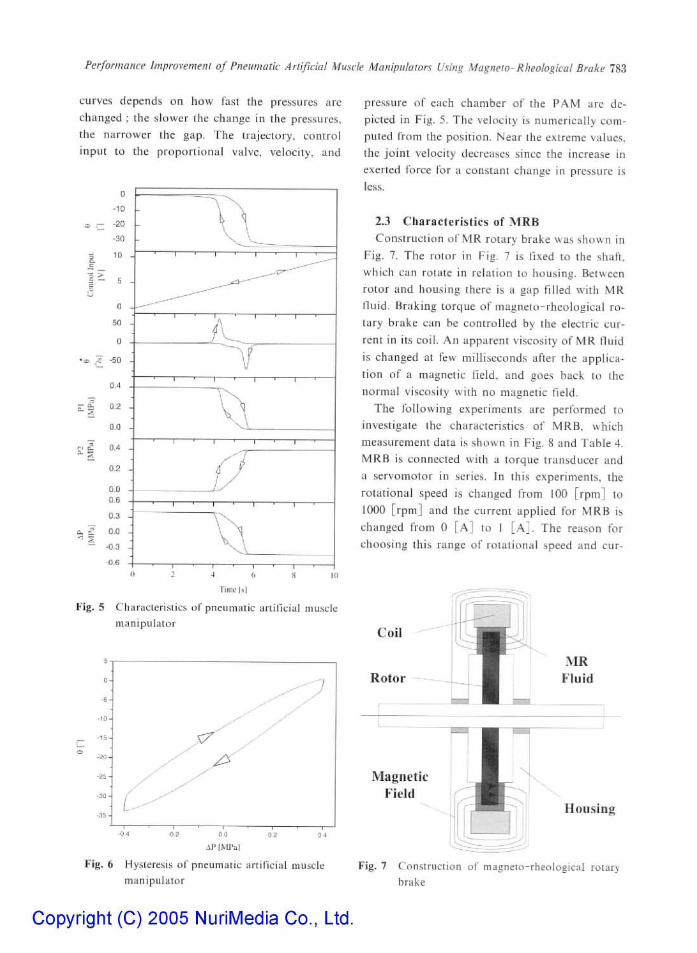
PAM. Figures 5 and 6 demonstrate the hysteresis
characteristics for the joint. This hysteresis can
be shown by rotating a joint along a pressure
trajectory from Pi = Pmav. P.^O to P ;=0 . P :=
Pmax and back again by incrementing and decre
menting the pressures by controlling the propor
tional \atve. The hysteresis of the P.A.M is sho»n
in Fig- 6. The width of the gap between the two
Copyright (C) 2005 NuriMedia Co., Ltd.
Performance Improvement of Pneumatic Artificial Muscle Manipulators Using Magnelo-Rheological Brake 7S3
curves depends on how last the pressures are changed ; the slower the change in the pressures, the narrower the gap. The trajectory, control input to the proportional valve, velocity, and
^ s
0,4
0,2
0.0
C'l
0.2
0.0 D,6
0.3
O.D
-0.3
-0.6
pressure of each chamber of the PAM are depicted in Fig, 5. The velocity is numerically eom-puled from the position. Near the extreme values, the joint velocity decreases since the increase in exerted force for a constant change in pressure is lcs,s.
2.3 Characteristics of MRB Construction of MR rotary brake was shown in
Fig. 7. The rotor in Fig. 7 is fixed to the shaft,
which can rotate in relation to housing. Between
rotor and housing there is a gap filled with MR
fluid. Braking torque of magneto-rheological ro
tary brake can be controlled by the electric cur
rent in its coil. An apparent viscosity of MR lluid
is changed at few milliseconds after the applica
tion of a magnetic field, and goes back to the
normal viscosity with no magnetic field.
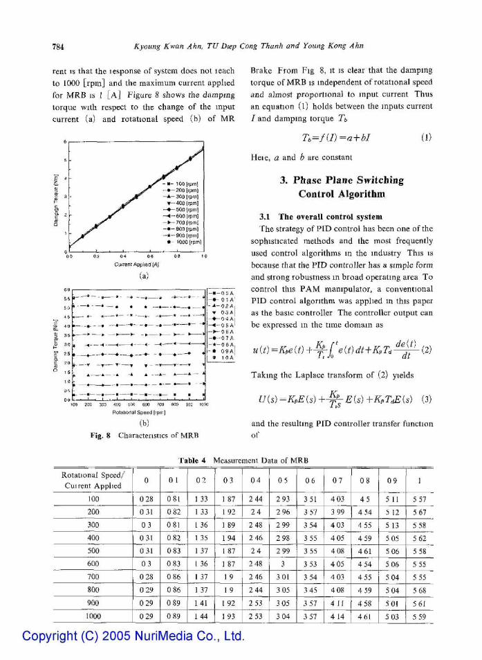
The following experiments are performed to
investigate the characteristics of MRB, which
measurement data is shown in Fig. S and Table 4.
MRB is connected with a torque transducer and
a servomotor in series. In this experiments, the
rotational speed is changed from 100 [rpm] to
1000 [rpm] and the current applied for MRB is
changed from 0 [ A ] to I [ A ] . The reason for
choosing this range of rotational speed and cur-
Tm]f I s
Fig. 5 Characteristics of pneumatic artificial muscle manipulator
Fig. 6 Hysteresis of pneumatic artiticial muscle manipulator
Housing
Fig. 7 Construction of magneto-rheological rotary brake
Copyright (C) 2005 NuriMedia Co., Ltd.
784 Kyoung Kwan Ahn, TU Diep Cong Thanh and Young Kong Ahn
rent is that the lesponse of system does not leach
to 1000 [rpm] and the maximum current applied
for MRB IS J [ A ] Figure 8 shows the damping
torque with respect to the change of the input
current (a) and rotational speed (b) of MR
Cuffent Applied [A|
01)
55
50
45
4 0
3 5
3 0
25
2 0
1 5
1 0
0 ^
^ _ - « ~
»— *-•—•--K . _
t "^^ ~
» 1 —
f '
«, i
t • —
• - - ™ B ^
•• B * - ™ » 1 —
„ * * 1_
...., —» • . -- » — • • - - ^ -
. ^ 4 4 -< -
*̂ * » ^ -^"T—~ •T" —~"T ¥ -
_ A __ _ i .A A
— i i -^-^a™~ —mi-
* . 9 _ _ ^ i j i,
^ A ^ ^ * — • * — *
- ^ » - ™ - ^ * • — - *
- - - i — • — '
—<-.—< < < - • — • - - • •
- T T » -
. - i ^ * — 1 ^ i
-™»— H II 9 , 4 . 1 , 1 . 1
- • - 0 0 A - • - 01 A
T 03A —•— 0 4 A - < - 0 6 A - » - - 0 6 A - • - - 0 7 A - * - 0 6 A , - • 0 9 A [
9 1 0 A
ZOO 300 400 500 600 700 600 90C lOOG
Bolational Speed Irpm]
(b) Fig. 8 Characteristics of MRB
Brake From Fig 8, it is clear that the damping
torque of MRB is independent of rotational speed
and almost proportional to input current Thus
an equation (l) holds between the inputs current
/ and damping torque Tb
T,=f(J)=a + bI (!)
Heie, a and b are constant
3. Phase Plane Switching Control Algorithm
3.1 The overall control system
The strategy of PID control has been one of the
sophisticated methods and the most frequently
used control algorithms in the industry This is
because that the PID controller has a simple form
and strong robustness m broad operating area To
control this PAM manipulator, a conventional
PID control algorithm was applied in this paper
as the basic controller The controller output can
be expressed in the time domain as
u(i)-- --Kpe{t)^^re{t)dt-\-KpZ deit) ,„.
Taking the Laplace transform of (2) yields
U{s)=KpE(s)+^E{s)+KpT^{s) (3)
and the resulting PID controller transfer function
of
Rotational Speed/
Cuirent Applied
100
200
300
400
500
600
700
800
900
1000
0
0 28
031
0 3
031
031
0 3
0 28
0 29
0 29
0 29
Table 4
0 1
081
0 82
081
0 82
0 83
0 83
0 86
0 86
0 89
0 89
0 2
1 33
133
1 36
1 35
1 37
1 36
1 37
1 37
141
144
VIeasurement Data of MRB
0 3
1 87
192
1 89
194
1 87
1 87
1 9
19
192
1 93
0 4
2 44
2 4
2 48
2 46
2 4
2 48
2 46
2 44
2_53j
2 53
0 5
2 93
2 96
2 99
2 98
2 99
3
3 01
3 05
3 05
3 04
0 6
351
3 57
3 54
3 55
3 55
3 53
3 54
3 45
3 57
3 57
0 7
4 03
3 99
4 03
4 05
4 08
4 05
4 03
4 08
4 11
4 14
0 8
4 5
4 54
4 55
4 59
461
4 54
4 55
4 59
4 58
461
0 9
5 11
5 12
5 13
5 05
5 06
5 06
5 04
5 04
SOi
5 03
1
5 57
5 67
5 58
5 62
5 58
5 55
5 55
5 68
561
5 59
Copyright (C) 2005 NuriMedia Co., Ltd.
Performance Improremeu! of Pneumatic Arlificial Muscle Manipiilalors Using Magneto-Rheohgical Brake 785
r-^- A'jji
-ny i
VLiH.ii!t:lu
Ciin'.L'rti.'r
PhiL<;c Plinc
Ci>iiliiilkr
HID Cnmrollt:r
PAM M:inipLil.iu>r
Fig. 9 Block diagram of control system
Uis) =Kp I
1 T,s (4)
A typical real-time implementation at sampling
sequence k can be expressed as :
i/{k)=Kpe{k)+u(k-])
+^eik) -luT. e{k)-e{k-\) (5)
where A'/,, Ti, Td. u(k) and eik) are the pro
portional gain, integral time, derivative time,
control input to the control valve and the error
between the desired set point and the output of
joint, respectively.
In addition, MRB is one of effective methods
to improve the control performance of the PAM
manipulator by reconciling both the damping
and response speed because it works in only llic
regions where the acceleration or deceleration is
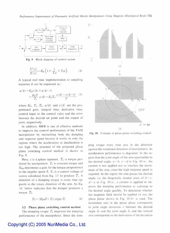
too high. The structure of the proposed phase
plane switching control method is shown in
Fig. 9.
Here, 5 is Laplace operator, Ta is torque pro
duced by manipulator, JI is constant torque and
KED determines a gain for the torque proportional
to the angular speed 6. Vc is a control voltage of
source calculated from Eq. (l) to produce Tc- A
direction of a damping torque is every lime op
posite to the rotary direction of the arm. So Eq.
(6) below indicates that the damper produces a
torque Tt-
T,= {KEDd+Tr}sign(9) (6)
3.2 Phase plane switching control method The damping torque Tb improves the damping
performance of the manipulator. Since the dam-
0.
(a)
= fie {b)
Fig. 10 Concept of phase plane switching control
ping torque every time acts in the direction
against the rotational direction of manipulator, its
acceleration performance is degraded. In the re
gion that the joint angle of the arm approaches to
the desired angle. a~ b, c—d'in Fig. 10(a), the
current is not applied not to interfere the move
ment of the arm, since the high response speed is
required. In the region the arm passes the desired
angle, i.e. the diagonally shaded areas of b — c.
d'-e in Fig. 10(a), a current is applied to im
prove the damping performance to converge to
the desired angle quickly. To determine whether
the magnetic field should be applied or not. the
phase plane shown in Fig. 10(b) is used. The
horizontal a.\is in the phase plane corresponds
to joint angle deviation e between the desired
angle dr and the joint angle d. and the \ertical
a.\is corresponds to the derivation of the deviation
Copyright (C) 2005 NuriMedia Co., Ltd.
786 Kyoiing Kwan Ahn, TU Diep Cong Thanh and Young Kong Ahn
e^—TT= — 9. Each poinl a — e on the phase
plane corresponds to each point a~ e in Fig. 10
(a ) . Here, the region with the application of
current is controlled by h [ s ~ ' ] , the gradient of
the line shown in Fig. 10(b) . The region under
the application of the damping torqtie expands
as I //1 decrease.
The effectiveness of the proposed controller
will be demonstrated through experiments with
various external inertia loads.
fr Refersnce PID Con-r-..=-
- PID CoriraJe-
4. Experimenal Results
Experiments were carried out with 3 cases of
external inertia loads (20. 60. 200 [kg-cm^]) and
the comparison between the conventional P ID
controller and the phase plane switching control
ler was presented.
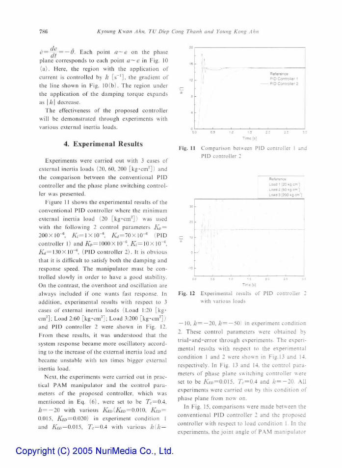
Figure 11 shows the experimental results of the
conventional PID controller where the minimum
external inertia load (20 [kg*cm^]) was used
with the following 2 control parameters A'p =
2 0 0 X [ 0 - ^ /<^,•=lX10-^ A ' d = 7 0 X 1 0 - * (F ID
controller I) and A p = 1 0 0 0 X IQ-^ / C = 10x 10"'.
/<•„:= 130 X I Q - ^ (FID controller 2) . It is obvious
that it is difficult to satisfy both the damping and
response speed. The manipula tor must be con
trolled slowly in order to have a good stability,
On the contrast, the overshoot and oscillation are
always included if one wants fast response. In
addit ion, experimental results with respect to 3
cases of external inertia loads (Load 1:20 [kg-
cm^]; Load 2:60 [ k g - c m ' ] ; Load 3:200 [kg-cm^])
and PID controller 2 were shown in Fig. 12.
From these results, it was understood that the
system response became more oscillatory accord
ing to the increase of the external inertia load and
became unstable with ten times bigger external
inertia load.
Next, the experiments were carried out in prac
tical PAM manipula tor and the control para
meters of the proposed controller, which was
mentioned in Eq. (6) , were set to be Tc=0 .4 ,
h=—2Q with various A ' £ £ ) ( A ' £ D = O . 0 I O . KED =
0.015. AE:J3=O.O20) in experiment condition I
and KED — O.QIS, TC — 0'^ with various h[h =
Fig. 11 Comparison between PID controller I and
PID controller 2
3Q
20
IQ
0
10
-
r'' ^ •
, 1 l | • 1
1
Hefer^B:*
Load 1 [20 kg cm')
Load 2 [60 kg.crn-'] :
Laatl 3 [300 kS-CTi'l
•
Time rs[
Fig. 12 Experimental results of PID controller 2
with various loads
— 10. /; = —20, h=—50) in experiment condi t ion
1. These control parameters were obtained by
t r i a l - and-e r ro r through experiments. The experi
mental results with respect to the experimental
condit ion 1 and 2 were shown in Fig. 13 and 14.
respectively. In Fig. 13 and 14. the control para
meters of phase plane switching controller were
set to be A £ D = 0 . 0 1 5 , r c = 0 . 4 and b=-20. -All
experiments were carried out by this condit ion of
phase plane from now on.
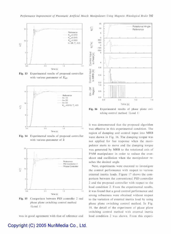
In Fig. 15, comparisons were made between the
conventional FID controller 2 and the proposed
controller with respect to load condi t ion 1. In the
experiments, the joint angle of P A M manipula tor
Copyright (C) 2005 NuriMedia Co., Ltd.
Performance ImproremeiU of Pneumatic Arlificial Muscle Manipulators Using Magneto- Rheological Brake 787
— Reference
h=-20. T =0.5
1 Time [s]
Fig. 13 Expeiimeiital resulis of proposed conlToller
with various parameter of KED
Reference h—10 h=-20
-• h=-50 K =0.015,1=0.5
0 5 1.0
T ime [sj
Fig, 14 E.Kperimental results of prupo.sed controller with various parameter of //
C '0
Reference PID Controller 2
- Phase Controller
Time [s]
Fig. 15 Comparison between PID controller 2 and phase plane switching control method (Load 1)
was in good agreement with that of reference and
9 .
cr
• iL^
cr
C L > L.
- s o < i ; Q_ fe o u
Q . <
— CO
O CE
^ S o a o
a= c O ,2
15
in
B
a 200
100
Q
•100
.200 1
4
OR
0 4
0.0
1.0
' A,
• Rotational Angle
Reference
\J
£l1f:iniln[l]1fi!'fl
11̂ 0,0 0 5 1 0 1 6
T ime [s]
Fig. 16 Experiniental results of phase plane swi-tchina control method (Load 1,1
it was demonstrated that the proposed algorithm was effective in this experimental condition. The region of daiTipiiig and control input into MRB were .shown in Fig. 16. The damping torque W'as not applied for fast response when the manipulator starts to move and the damping torque was generated by MRB to the rotational axis of PAM manipulator in order (o reduce the overshoot and oscillation when the manipulator reaches the desired angle.
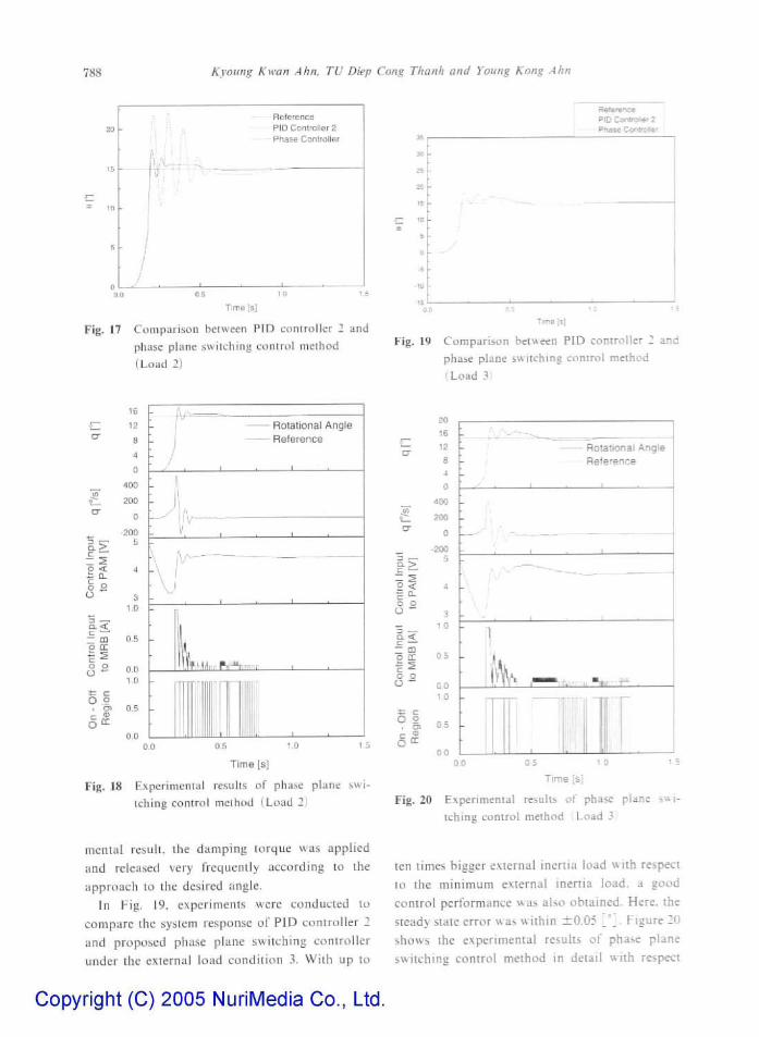
Nexi. experiments were executed (o investigate the control performance with respect to various external inertia loads. Figure 17 shows the comparison between the conventional PID controller 2 and the proposed controller with respect to the load condition 2. From the experimental results, it was found that a good control performance and strong robustness were obtained without respect to the variation of external inertia load by using phase plane switching control method. In 1-ig. 18, the detail of the experiment of phase plane switching control method with external inertia load condition 2 was shown. From this experi-
Copyright (C) 2005 NuriMedia Co., Ltd.
788 Kyoung Kwan Aim. TU Diep Cong Thanh and Young Kong Ahn
i/U^lA
Reference PID Controller 2 Phase Cantrollsr
Time [s|
Fig. 17 Compnri.soii between PID controller 2 and phase plane switching control method (Load 2)
Reference PID Cixan^er 2 Phase Cor^roter
Fig, 19 Comparison between P!D controller 2 and phase plane switching conirol method (Load 3)
o < ~ a. a y o
t : '—' — CD
o o
O .9
16
1?
8
4
0
400
200
0
200 5
3 1.0
0.0 1.0
0.5
0.0
- - ' tv-
• Rolalional Angle • Reference
,v—•
iff .̂̂ «n.- M B a
l l iL 0.0 0.5 1,0
'— O"
y>
Cl cr
D .—1 Q - > t • - -~ Si 2 < r ^ o o O ~
._ CL< E ^ '
— m o cc F ^ o o O
t c O a
1 a i
20
1fi
v^ » 4
0
400
•iVM
0
-200 5
4
3
1 0
Ob
0,0 1,0
OS
Time [s]
Fig. 18 Experiment 111 results of phase plane swi
tching control melhod ( Load 2.)
mental result, Ihe damping torque was applied
and released very frequently according to the
approach to the desired angle.
In Fig. 19, experiments were conducted to
compare the system response of FID controller 2
and proposed phase plane switching controller
tinder the external load condition .1. With up to
Copyright (C) 2005 NuriMedia Co., Ltd.
00
' Rotational Angle Reference
,̂ A-'
k^
Time [sj
Fig. 20 Experimental results of phase plane sni
tching control method ;Load 3,
ten times bigger external inertia load with respect
to the minimum external inertia load, a good
control performance was also obtained. Here, the
steady state error was within ±0,05 S^ • Figure 20
shows the experimental results of phase plane
switching control method in detail with respect
Performance Improvement of Fneimwuc Artifkial Muscle Manipulators Uung Magneto-Rheologtcal Brake 789
to the exteinal inertia load condition 3 It was
concluded that the proposed contioiler was very
elective m the high gam comiol, fast rei,ponie
and robust stability with ten times changes of
external inertia load
However, there still remain some problems
such as the difficulty of the selection of the opti
mal control parameteis of proposed phase plane
switching controller in ordei to gee a good control
performance of the PAM mtmipuluor, especially
with various external ineitia loads
There is no pievious reseaich to find optimal
contiol paramctess in case of phase plane swi
tching control method up to no\\ As futuie study,
we are planning to design a new intelligent con
trol algorithm using neuial network with phase
plane switching control method, u'hich utilizes
the adaptive and learning capabilities of neural
network in oider to find the optimal control
paiameters with lespeci to various external incitia
loads
5. Conclusions
In this papet, a new phase plane switching
control method using the magneto-theological
brake was applied to the pneumatic artificial
muscle manspulatoss in ordei to improve the con
trol petformance with various external inoitia
loads
From the expeiimeiu<il results, the newly pro
posed contioller was very effectively in high gam
control with lespect to the 1,000 [%] external
inertia load variation And the steady state en or
with respect to vaiious loads was reduced within
± 0 05 ["] It was verified that the proposed con-
trot algorithm presented m this study had simple
structure and had better dynamic propeity, strong
lobustness and it was suitable foi the control of
various plants, including linear and nonlinear
piocess, compaied to the conventional PID con-
troUei
By using MRB as a vaiiabie damper, the dam
ping torque was controlled by the applying mag
netic field strength and the position control per
formance was improved without the decrease of
response speed by separating the region wheie the
Copyright (C) 2005 NuriMedia Co., Ltd.
damper pioduces an damping torque by phase
plane switching contiol method
The icsulis show thai the MRB is one of
effective methods to develop a practically avail
able human ftiendly robot by using the PAM
manipulatoi
Acknowledgments
This woik was supported partly by the Korea
Science and Engineeiing f-oundation ( K O S E F )
through the Research Center for Machine Parts
and Mateiials Processing (ReMM) at University
of Ulsan
References
Ahn, K K , Lee, B R and Yang, S Y , 2003,
'Design and Experimental Evaluation of a Ro
bust foice Contioller tor a 6-Link Electro-
Hydraulic Manipulatoi Via H Infinity Control
Theory," in KSME, Int, Jour, Vol 17, No 7,
pp 999-1010
Ahn, K K and Tii. D C T , 2004, " Improve
ment of the Control Peiformance of Pneumatic
Artificial Manipulators Using an Intelligent Swi
tching Control Method," in KSME, Int, Jour,
Vol 18, No 8, pp 1388-1400
Bdlasubramanian, V and Rattan, K S , 2003,
"Feedforward Control of a Non-Lmear Pneuma
tic Muscle System Using Fuzzy Logic," in IEEE
Int. Conf. Fuzzy Systems, Vol 1, pp 272— 277
Bowler, C J , Caldwell, D G and Medrano-
Ceida, G A , 1996, '" Pneumatic Muscle Actua
tors, Musculatuie for an Anthropomoiphic Ro
bot Arm," in Proc lEE Colloqtum on Actuator
Technology Current Practice and New Develop
ments, London, pp 8/1 — 8/5
Cai, D and Yamauia, H , 1997, "A VSS Con
trol Method foi a Manipulatoi Driven by an
McKibben Aitificial Muscle Actuatoi," Electron,
Commun, Japan, Voi 80, No 3, pp 55 — 63
Caldwell, D G , Mediano-Cerda, G A and
Goodwin, M J , 1995, 'Control of Pneumatic
Muscle Actuators," IEEE Contr, Syst, Mag,
Vol 15, No 1, pp 4 0 - 4 8
Caldwell, D G , Medrano-Cerda, G A and
790 Kyoung Kwan Ahn, TU Diep Cong Thanh and Young Kong Ahn
Goodwin, M J , 1994, "Characteristics and
Adaptive Control of Pneumatic Muscle Actuators
foi a Robotic Elbow," in Proc, IEEE Int, Conf
Robotics and Automation, yo\ 4, pp 3558 — 3563
Carbonell, P , Jiang, Z P and Repperger, D
W , 2001, "Nonlinear Control of a Pneumatic
Muscle Actuator Backstepping vs Sliding-
Mode," in Proc, IEEE Int, Conf., Control Ap
plications, Mexico City, Mexico, pp 167—172
Chan, S W , Lilly, J H , Repperger, D W and
Berlin, I E , 2003, "Fuzzy P D + 1 Learning Con
trol for a Pneumatic Muscle," in IEEE Int.,
Conf. Fuzzy Systems, Vol 1, pp 278 — 283
Folgheraiter, M , Gini, G , Perkowski, M and
Pivtoraiko, M , 2003, "Adaptive Reflex Control
for an Artificial Hand," in Proc, SYROCO 2003,
Symposium on Robot Control, Ho II id ay Inn,
Wroclaw, Poland
Gaylord, R H , 1958, United States Patent 2,
844,126
Guihard, M and Gorce, P , 1999, "Dynamic
Control of an Artificial Muscle Arm," m Proc,
IEEE Int., Conf,, Systems, Man and Cybernetics,
Le Touque, France, Vol 4, pp 813~818.
Hamerlain, M , 1995, "An Anthropomorphic
Robot Arm Driven by Aitificial Muscles Using
a Variable Structure Control," m lEEE/RSJ
Int., Conf, Intelligent Robots and Systems, Vol
1, pp 550-555
Hesselroth, T , Sarkar, K , Patrick van der
Smagt, P and Schulten, K , 1994, "Neural Net
work Control of a Pneumatic Robot Arm," IEEE
Trans Syst., Man., Cybernetics , Vol 24, No 1,
pp 2S~3S
Iskarous, M and Kawamura, K , 1995, "Intel
ligent Control Using a Neuio-Fuzzy Network,"
in Proc, IEEE/RSI Int., Conf, Intelligent Robots
and Systems, Vol 3, pp 350-355
Klute, G K , Czerniecki, J M and Hannaford,
B , 2002, "Artificial Muscles Actuators for Bio-
robotic Systems," Accepted for Publication, Int,
Jour, Robotics Research
Klute, G K , Czerniecki, J and Hannaford, B ,
1999, "McKibben Artificial Muscles Actuators
with Biomechanical Intelligence," Proc, IEEE/
ASME Int., Conf, Advanced Intelligent Mecha-
tronics, pp 221 — 226
Copyright (C) 2005 NuriMedia Co., Ltd.
Klute, G K , Czerniecki, J and Hannaford, B ,
2000, "Artificial Tendons Biomechanical Prop
erties foi Prosthetic Lower Limbs," Proc, IEEE
Int., Conf, Medical Physics and Biomedical
Engineering, Vol 3, pp. 1972—1975
Klute, G K , Czerniecki, J and Hannaford, B ,
2000, "Muscle-Like Pneumatic Actuators for Be-
low-Knee Prostheses," Proc Int, Conf, New
Actuators, pp. 289 — 292
Koeneman, E J , Schultz, R S , Wolf, S L ,
Herring, D E and Koeneman, J B., 2004, "A
Pneumatic Muscle Hand Therapy Device," Proc,
lEEE/EMBS Int, Conf , pp 2711-2713
Medrano-Cerda, G A , Bowler, C J and
Caldwell, D G , 1995, "Adaptive Position Con
trol of Antagonistic Pneumatic Muscle Actua
tors," in Proc EEE/RSJ Int., Conf, Intelligent
Robots and Systems, Human Robot Interac
tion and Cooperative Robots, Pittsburgh, PA,
pp 378-383
Nickel, V L , Perry, J and Garrett, A L , 1963,
"Development of Useful Function m the Severely
Paralyzed Hand," in Jour , Bone and Joint Sur
gery, Vol, 45A, No 5, pp 933-952
Noritsugu, T. and Tanaka, T , 1997, "Applica
tion of Rubber Artificial Muscle Manipulator
as a Rehabilitation Robot," in IEEE/ASME
Trans, Mechatronics, Vol 2, pp 259 — 267
Noritsugu, T , Tsuji, Y and Ito, K , 1999,
"Improvement of Contiol Performance of Pneu
matic Rubber Artificial Muscle Manipulator by
Using Electrorheological Fluid Damper," in
Proc, IEEE Int, Conf, Systems, Man and Cy
bernetics, Seattle, Washington, Vol 4, pp 788 —
793
Osaka, K , Kimura, T and Ono, T , 1990, "i7„
Control of a Certain Nonlinear Actuator," in
Proc, IEEE Int, Conf, Decision and Control,
Honolulu, Hawai, Vol 1, pp 370-371
Patrick van der Smagt, P , Groen, F and
Schulten, K , 1996, "Analysis and Control of a
Rubbertuator Arm," Biol Cybernet, Vol 75,
pp 433-440
Raparelli, T , Zobel, P B and Durante, F ,
2001, "The Design of a 2 DOF Robot for Func
tional Recovery Theiapy Driven by Pneumatic
Muscles," Int, Workshop on robotics in ALPA —
Performance Improvement of Pneumatic Artificial Muscle Manipulators Using Magneto-Rheologwal Brake 791
DRIA-DANUBE region
Raparelh, T , Zobel, P B and Durante, F ,
2003, "DeveJopment of a Robot Driven by Pneu
matic Muscles," Proc, RAAD, Workshop on ro
botics in ALPA — DRIA-DANUBE region
Schulte, H F , 1961, "The Characteristics of
the McKibben Artificial Muscle," The Applica
tion of External Power in Prosthetics and Ortho
tics, National Academy of Sciences-National Re
search Council Appendix H, pp 94—1 i j
Tondu, B and Lopex, P , 2000, "Modeling and
Control of Mckbben Artificial Muscle Robot
Actuate IS," IEEE Contr, Syst., Mag , Vol 20,
No 1, pp 15-38
Tsagarakis, N , Caldwell, D G and Medrano-
Ceida, G A , 1999, "A 7 DOF Pneumatic Muscle
Actuator (pMA) Povveied Exoskeleton," IEEE
International Wokshop on Robot and Human
Interaction, Pisa, Italy, pp 327 — 333
Zobel, P B , Durante, F and Raparelh, T ,
1999, "The Expellence of the Univeisity of
L'Aquila on the Pneumatic Muscle Actuators for
a 2 DOF Manipulatoi for Function Recovery
Therapy," Seminar on Biomechanics, Warsaw,
Poland
Copyright (C) 2005 NuriMedia Co., Ltd.
Related Documents