J Electr Eng Technol.2018; 13(5): 1965-1977 http://doi.org/10.5370/JEET.2018.13.5.1965 1965 Copyright ⓒ The Korean Institute of Electrical Engineers This is an Open-Access article distributed under the terms of the Creative Commons Attribution Non-Commercial License (http://creativecommons.org/ licenses/by-nc/3.0/) which permits unrestricted non-commercial use, distribution, and reproduction in any medium, provided the original work is properly cited. Performance Evaluation of Regenerative Braking System Based on a HESS in Extended Range BEV Kunagone Kiddee † and Werachet Khan-Ngern* Abstract – This paper proposed a regenerative braking system (RBS) strategy for battery electric vehicles (BEVs) with a hybrid energy storage system (HESS) driven by a brushless DC (BLDC) motor. In the regenerative braking mode of BEV, the BLDC motor works as a generator. Consequently, the DC-link voltage is boosted and regenerative braking energy is transferred to a battery and/or ultracapacitor (UC) using a suitable switching pattern of the three-phase inverter. The energy stored in the HESS through reverse current flow can be exploited to improve acceleration and maintain the batteries from frequent deep discharging during high power mode. In addition, the artificial neural network (ANN)-based RBS control mechanism was utilized to optimize the switching scheme of the vehicular breaking force distribution. Furthermore, constant torque braking can be regulated using a PI controller. Different simulation and experiments were implemented and carried out to verify the performance of the proposed RBS strategy. The UC/battery RBS also contributed to improved vehicle acceleration and extended range BEVs. Keywords: Battery electric vehicles (BEV), Hybrid Energy Storage System (HESS), Three-Phase Inverter, Regenerative Braking System (RBS), Ultracapacitor (UC). 1. Introduction Battery Electric Vehicle (BEV) offers definite advantages including high efficiency, environmental responsiveness, fashionability, reduced noise pollution, reduced maintenance and energy efficiency. Most importantly, the BEV can be used to reduce carbon emissions [1-4]. The BEV relies on batteries for use as the main Energy Storage System (ESS) components. However, using electrochemical batteries as the sole energy storage device of the BEV has several limitations including high initial cost, limited driving range, short cycling life and limited power density [4, 5]. In addition, the batteries need to be able to provide the power demand of the BEV such as acceleration or driving uphill. Therefore, the batteries have to be oversized in order to deliver these functions. Ultracapacitors (UCs) with batteries based Hybrid Energy Storage System (HESS) can be utilized to improve the acceleration of vehicles and significantly prolong the life cycle of the batteries [5-17]. Owing to the rapid growth of UC technologies, one type of ultracapacitor technology is the Electric Double Layer Capacitors (EDLC), which offers many outstanding features such as high power density and long life-cycle [9, 11]. Combining the features of the UC and batteries based HESS has significant benefits such as improvement acceleration or in the high power mode of the BEV and significantly prolonged life cycle of the batteries, which is due to the UC assisting the batteries during peak power demand by the vehicle [12- 18]. In addition, the high power density of the UC can also be used to effectively harvest regeneration energy through reverse current flow during regenerative braking mode, which leads to increased driving range for the vehicle. Various topologies of HESS are described in [5-21]. The most widely utilized and researched is the battery/UC topology for HESS. The objective of combining batteries with a UC is to construct a hybrid energy storage system with the high power density of a UC and the high energy density of a battery. Since the HESS needs additional two energy storage elements and power electronic interface, such as a bidirectional DC/DC converter, it is typically not cost effective [14, 18]. Furthermore, the bidirectional DC/ DC converter needs to match the power of the HESS module and is utilized to convey the energy flow between the UC and the battery pack. Hence, the efficiency of regenerative braking is decreased due to the power dissipation of the high power electronic interface. It also significantly increases overall system costs [5-19]. In this paper, a configuration is proposed for appropriate interaction between two energy storage elements (UC/ Battery) based on the HESS. The purposed HESS includes the battery pack, UC module, power diode and unidirectional DC/DC buck converter. In addition, a proposed a HESS topology with four operation modes is discussed in detail. Furthermore, a new RBS strategy is optimized for the proposed HESS. During the braking or deceleration mode of the vehicle, the suitable switching pattern of the three- † Corresponding Author: Dept. of Electrical Engineering, Faculty of Engineering, King Mongkut's Institute of Technology Ladkrabang, Thailand. ([email protected]) * Dept. of Electrical Engineering, Faculty of Engineering, King Mongkut's Institute of Technology Ladkrabang, Thailand. ([email protected]) Received: December 26, 2017; Accepted: May 4, 2018 ISSN(Print) 1975-0102 ISSN(Online) 2093-7423

Welcome message from author
This document is posted to help you gain knowledge. Please leave a comment to let me know what you think about it! Share it to your friends and learn new things together.
Transcript
J Electr Eng Technol.2018; 13(5): 1965-1977 http://doi.org/10.5370/JEET.2018.13.5.1965
1965Copyright ⓒ The Korean Institute of Electrical Engineers
This is an Open-Access article distributed under the terms of the Creative Commons Attribution Non-Commercial License (http://creativecommons.org/ licenses/by-nc/3.0/) which permits unrestricted non-commercial use, distribution, and reproduction in any medium, provided the original work is properly cited.
Performance Evaluation of Regenerative Braking System Based on a HESS in Extended Range BEV
Kunagone Kiddee† and Werachet Khan-Ngern*
Abstract – This paper proposed a regenerative braking system (RBS) strategy for battery electric vehicles (BEVs) with a hybrid energy storage system (HESS) driven by a brushless DC (BLDC) motor. In the regenerative braking mode of BEV, the BLDC motor works as a generator. Consequently, the DC-link voltage is boosted and regenerative braking energy is transferred to a battery and/or ultracapacitor (UC) using a suitable switching pattern of the three-phase inverter. The energy stored in the HESS through reverse current flow can be exploited to improve acceleration and maintain the batteries from frequent deep discharging during high power mode. In addition, the artificial neural network (ANN)-based RBS control mechanism was utilized to optimize the switching scheme of the vehicular breaking force distribution. Furthermore, constant torque braking can be regulated using a PI controller. Different simulation and experiments were implemented and carried out to verify the performance of the proposed RBS strategy. The UC/battery RBS also contributed to improved vehicle acceleration and extended range BEVs.
Keywords: Battery electric vehicles (BEV), Hybrid Energy Storage System (HESS), Three-Phase Inverter, Regenerative Braking System (RBS), Ultracapacitor (UC).
1. Introduction Battery Electric Vehicle (BEV) offers definite advantages
including high efficiency, environmental responsiveness, fashionability, reduced noise pollution, reduced maintenance and energy efficiency. Most importantly, the BEV can be used to reduce carbon emissions [1-4]. The BEV relies on batteries for use as the main Energy Storage System (ESS) components. However, using electrochemical batteries as the sole energy storage device of the BEV has several limitations including high initial cost, limited driving range, short cycling life and limited power density [4, 5]. In addition, the batteries need to be able to provide the power demand of the BEV such as acceleration or driving uphill. Therefore, the batteries have to be oversized in order to deliver these functions. Ultracapacitors (UCs) with batteries based Hybrid Energy Storage System (HESS) can be utilized to improve the acceleration of vehicles and significantly prolong the life cycle of the batteries [5-17]. Owing to the rapid growth of UC technologies, one type of ultracapacitor technology is the Electric Double Layer Capacitors (EDLC), which offers many outstanding features such as high power density and long life-cycle [9, 11]. Combining the features of the UC and batteries based HESS has significant benefits such as improvement acceleration or in
the high power mode of the BEV and significantly prolonged life cycle of the batteries, which is due to the UC assisting the batteries during peak power demand by the vehicle [12-18]. In addition, the high power density of the UC can also be used to effectively harvest regeneration energy through reverse current flow during regenerative braking mode, which leads to increased driving range for the vehicle.
Various topologies of HESS are described in [5-21]. The most widely utilized and researched is the battery/UC topology for HESS. The objective of combining batteries with a UC is to construct a hybrid energy storage system with the high power density of a UC and the high energy density of a battery. Since the HESS needs additional two energy storage elements and power electronic interface, such as a bidirectional DC/DC converter, it is typically not cost effective [14, 18]. Furthermore, the bidirectional DC/ DC converter needs to match the power of the HESS module and is utilized to convey the energy flow between the UC and the battery pack. Hence, the efficiency of regenerative braking is decreased due to the power dissipation of the high power electronic interface. It also significantly increases overall system costs [5-19].
In this paper, a configuration is proposed for appropriate interaction between two energy storage elements (UC/ Battery) based on the HESS. The purposed HESS includes the battery pack, UC module, power diode and unidirectional DC/DC buck converter. In addition, a proposed a HESS topology with four operation modes is discussed in detail. Furthermore, a new RBS strategy is optimized for the proposed HESS. During the braking or deceleration mode of the vehicle, the suitable switching pattern of the three-
† Corresponding Author: Dept. of Electrical Engineering, Faculty of Engineering, King Mongkut's Institute of Technology Ladkrabang, Thailand. ([email protected])
* Dept. of Electrical Engineering, Faculty of Engineering, King Mongkut's Institute of Technology Ladkrabang, Thailand. ([email protected])
Received: December 26, 2017; Accepted: May 4, 2018
ISSN(Print) 1975-0102 ISSN(Online) 2093-7423
Performance Evaluation of Regenerative Braking System Based on a HESS in Extended Range BEV
1966 │ J Electr Eng Technol.2018; 13(5): 1965-1977
phase inverter is activated; the voltage of DC-link can be boosted. Hence, the power diode is forward biased. Then, regenerative braking energy is transferred directly to the UC module without using any additional power electronic interface. The voltage of DC-link is regulated by differentiation of the PWM duty-cycle in the three-phase inverter. Consequently, in case of the UC is almost charged, regenerative braking energy can be harvested through the battery pack. In the proposed strategy, the efficiency of regenerative braking energy is increased due to the elimination of power electronics interfaces. Furthermore, braking force distribution is improved via the Multilayer Perceptron (MLP) function in an Artificial Neural Network (ANN) controller. Simultaneously, the PI controller is used to regulate the PWM duty-cycle in the three-phase inverter to maintain constant torque braking. The organization of this research is as follows: Section 1 is the introduction. Section 2 discusses the UC/battery HESS topology and operation modes. Section 3 describes the ANN-based control mechanism of the proposed regenerative braking system (RSB), while Section 4 deals with the simulations and experimental results of the proposed RBS. The concluding remarks are provided in Section 5
2. The Proposed HESS Topology and Operation
Modes The configuration of the proposed HESS topology is
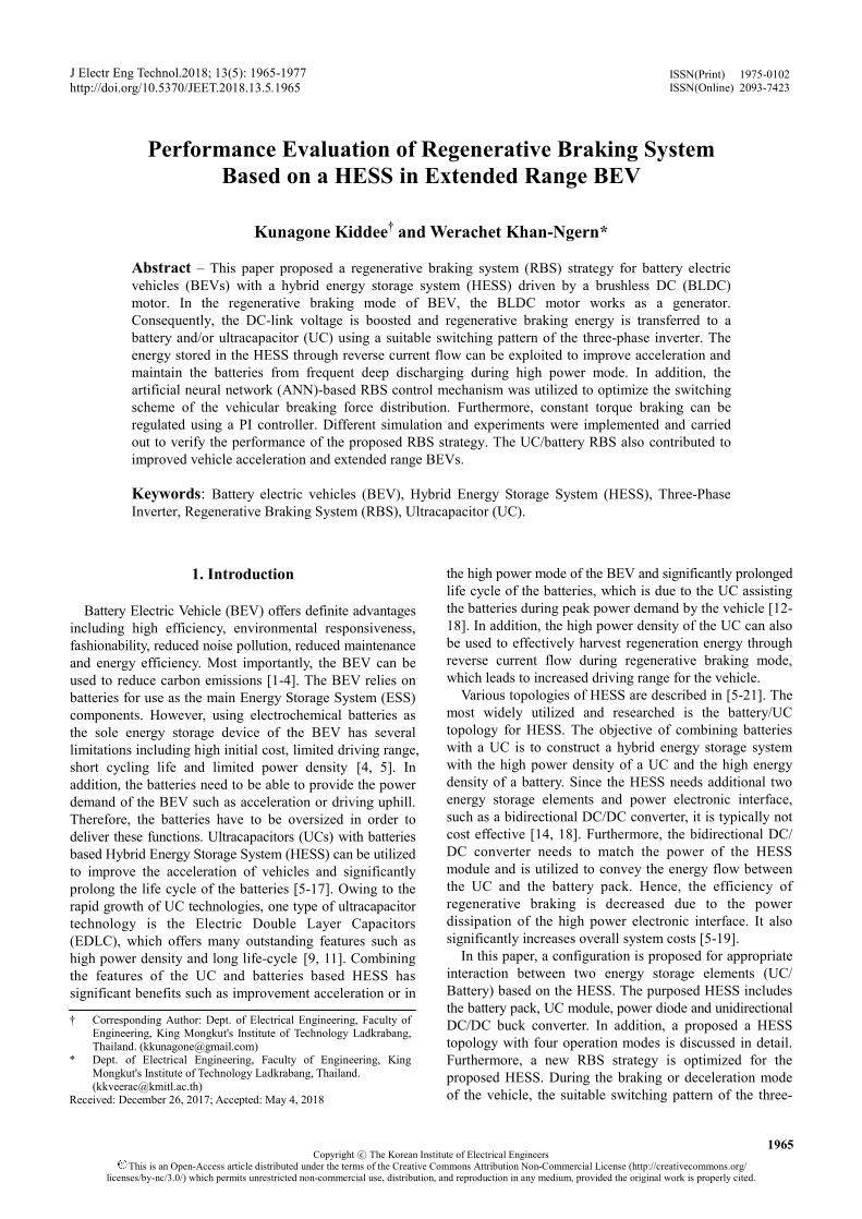
shown in Fig. 1. In the proposed HESS topology, the voltage of DC-link can be maintained relatively constant due to the DC-link being directly connected to the battery pack. The battery pack is connected to the UC module through a DC/DC buck converter. In addition, the voltage of the UC module is controlled to keep it higher than the battery pack voltage. The UC module is paralleled with the battery pack through a regenerative diode. Meanwhile, the proposed HESS is used to supply the BLDC motor through the three-phase inverter, att = dclink ≤ UC which att, dclink and UC refer to voltage of the battery pack, DC-link, and UC module respectively. In normal situations, the battery has enough power to supply the three-phase BLDC motor. Thus, the battery pack can handle the load demand alone. During high power modes such as vehicle acceleration or high speeds, the UC module assists to supply the BLDC motor with the battery pack through the
unidirectional DC/DC buck converter. In normal driving mode, the regenerative diode is always reverse biased. The buck converter is regulated to maintain UC voltage greater than the voltage of the battery pack. In braking mode, the BLDC motor acts as a generator [22-23]. Therefore, by utilizing the IGBTs in the three-phase inverter with inductances in the three-phase BLDC motor and a suitable switching pattern, the inverter can be boosted. Con-sequently, in regenerative braking conditions, the power diode is forward biased due to the voltage of DC-link being boosted. Therefore, energy can be efficiently stored through the UC module during the braking process.
Different individual cells of the two energy storage elements are required to be utilized. A degree of freedom arises for the distribution of power demand. Effectively splitting the power demand of the BEV between the UC module and the battery pack is a major challenge. Utilizing higher voltage for the UC module has many advantages from implementation in comparison with utilizing higher voltage of the batteries. On the other hand, the State of Charge (SOC) of the UC can be easily measured due to being proportional to the UC voltage. Moreover, active cell balancing circuits in the UC module are easier to be implemented and can reduce the overall cost of the system.
The proposed HESS with unidirectional DC/DC buck converter and three phase inverter can be separated into four different operation modes of BEV which are discussed in detail below.
2.1 Normal or low power mode
In the normal mode, since the battery has enough power
to supply the required power demand for the BEV, the voltage of the UC can be maintained higher than the battery pack voltage. Consequently, the power demand is equal or less than the battery power. This operating mode is referred to as normal mode. Fig. 2 shows energy flow for the normal mode of operation in the proposed HESS. In the normal mode, the power diode is reverse biased since the voltage of the UC module is higher than the battery pack voltage. As a result, the battery pack supplies the BLDC motor alone in this condition.
2.2 Acceleration mode
In the acceleration mode of the vehicle, the required
Fig. 1. Configuration of the proposed HESS
Fig. 2. Energy flow in normal or low power mode of the
proposed HESS
Kunagone Kiddee and Werachet Khan-Ngern
http://www.jeet.or.kr │ 1967
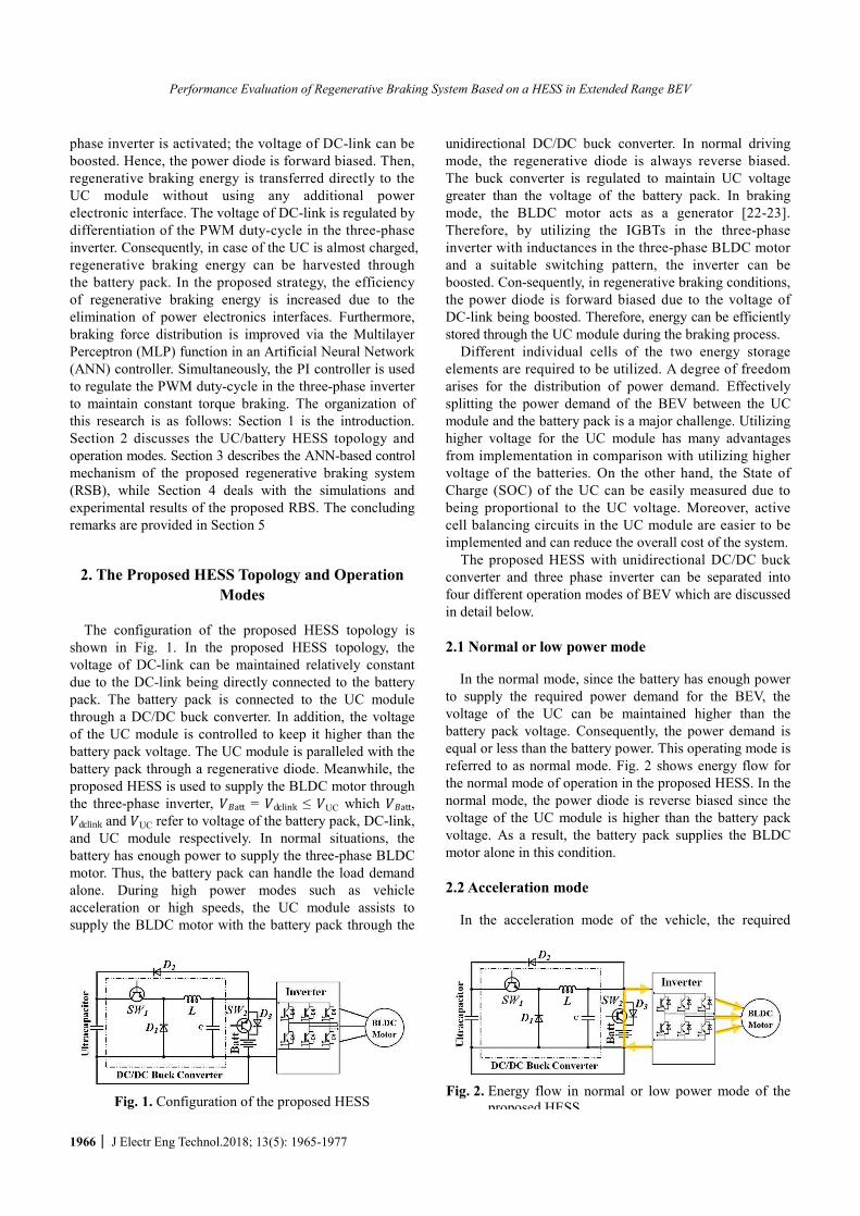
power demand is greater than available by battery power. In this condition, battery voltage can no longer be maintained due to the battery suffering frequent deep discharge cycles. Vehicle acceleration could also be degraded as a result. In this condition, the UC will start to assist the battery pack via the DC-DC buck converter when the voltage of the UC is higher than the minimum threshold (UC ≥UCmth). If the UC voltage drops below the battery voltage, the battery might unnecessarily charge the UC module in the circumstance, which increases the stresses in the battery pack. Hence, the UC only provides assistance to the battery pack until the UC voltage is higher than the battery voltage, which is adjusted by the loop control system strategy. In this condition, the regenerative diode (D2) is usually reverse biased. The energy from both the UC bank and the battery pack is also providing power to the BLDC motor. Energy flow in the acceleration mode is shown in Fig. 3.
2.3 Regenerative braking with UC mode
During vehicle braking, in this mode, can be divided into
two events. In Event I, the voltage of DC-link must be boosted. Hence 2 is forward biased and regenerative braking energy could be absorbed by the UC module, which is referred to as regenerative braking with UC. The energy flow of the regenerative braking with UC is shown in Fig. 4. A boost circuit of the three-phase inverter can be formed. High sides of the switches of the half-bridge are turned off and the low sides of the switches are pulse width modulated. In addition, this operation mode is activated only when UC ≤ UC in which UCmax is the maximum voltage limit of the UC module that is commonly analyzed for secure operating systems.
2.4 Regenerative braking with battery mode
Fig. 5 shows the energy flow of regenerative braking in
Event II, which is referred to the regenerative braking with battery. In this condition, the energy of regenerative braking cannot be transferred to the UC module. In the operation principle of this condition, the voltage of DC-link can be boosted. Hence 3 is forward biased and braking energy will be absorbed by the battery pack via D3. While the voltage of DC-link is boosted for achievement of
regenerative braking by the HSC, both 2 and 3 are forward biased.
It should be noted that Fig. 4 is only operated in VBatt > Vdclink > VUC, and Fig. 5. is only operated in VBatt< Vdclink < VUC. In other cases, the regenerated current flows in both sides, including the UC and battery. Thus, it cannot control the magnitude of the charging current. It is only determined by the voltage of the battery, DC-link, and UC.
3. Control strategy of the proposed Regenerative Braking System
3.1 The DC/AC inverter concepts
The equivalent circuit of the three-phase DC/AC inverter
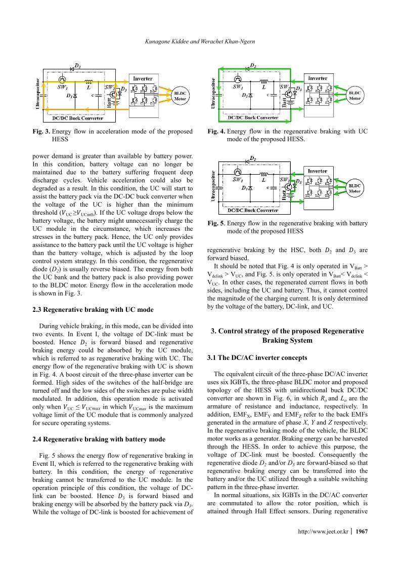
uses six IGBTs, the three-phase BLDC motor and proposed topology of the HESS with unidirectional buck DC/DC converter are shown in Fig. 6, in which Ra and La are the armature of resistance and inductance, respectively. In addition, EMFX, EMFY and EMFZ refer to the back EMFs generated in the armature of phase X, Y and Z respectively. In the regenerative braking mode of the vehicle, the BLDC motor works as a generator. Braking energy can be harvested through the HESS. In order to achieve this purpose, the voltage of DC-link must be boosted. Consequently the regenerative diode D2 and/or D3 are forward-biased so that regenerative braking energy can be transferred into the battery and/or the UC utilized through a suitable switching pattern in the three-phase inverter.
In normal situations, six IGBTs in the DC/AC converter are commutated to allow the rotor position, which is attained through Hall Effect sensors. During regenerative
Fig. 3. Energy flow in acceleration mode of the proposed
HESS
Fig. 4. Energy flow in the regenerative braking with UC
mode of the proposed HESS.
Fig. 5. Energy flow in the regenerative braking with battery
mode of the proposed HESS
Performance Evaluation of Regenerative Braking System Based on a HESS in Extended Range BEV
1968 │ J Electr Eng Technol.2018; 13(5): 1965-1977
braking, the high side IGBTs of the half bridge are turned off and the low side switches are controlled by the PWM to choose the suitable switching pattern. The three-phase back-EMFs, current of the three-phase armature, suitable switching patterns and Hall Effect signals are shown in Fig. 7. During the regenerative braking condition, six rotation time periods and only an individual IGBT is turned on and off during each time period.
3.2 Tractive Force of the BEV
The kinematics of vehicle model is used for evaluation
of the dynamic traction power requirement for the BEV powertrain [24-26]. Normally, driving forces can be separated into four main segments which are presented below:
3.2.1 Energy loss associated with rolling resistance
The force to overcome that resists the motion of a tries
rolling on the road, which is called rolling friction or rolling resistance, can be calculated as:
Roll RollF K mgcosθ= (1)
where KRoll is the rolling resistance coefficient, m is mass
of the vehicle (kg), is the slope angle and g is the acceleration of gravity constant (m/s2).
3.2.2 Aerodynamic loss
This loss results from air resistance force against the
body of the vehicle. Aerodynamic loss can be calculated as:
212A d fF ρC A v= (2)
In (2), is the density of air (kg/m3), Cd is the coefficient
of drag force, Af is the vehicle frontal area (m2) and v is the speed of the vehicle (m/s2).
3.2.3 Gradient force
In certain driving conditions such as climbing resistance,
inclined road force and uphill driving, gradient force is generated via gravitational forces, which significantly affects the performance of the vehicle. Gradient resistance force can be represented as:
gF mgsinθ= (3)
3.2.4 Transient force
This is the required force to acceleration or deceleration
of the vehicle and can be calculated as: m dvdt
. Hence, the
required force for the front and rear wheels of the vehicle can be calculated as:
T Roll A gdvF F F F mdt
= + + + (4)
Substituting (1)-(3) in (4) yields:
212T Roll d f
dvF K mgcosθ ρC A v mgsinθ mdt
= + + + (5)
In (5), FT is the required force supplied by the vehicle
powertrain to driven the vehicle. Eq. (5) can also be used to reach the required braking force to breaking of the vehicle in a predestine distance specified.
3.3 Regenerative braking control strategy for the
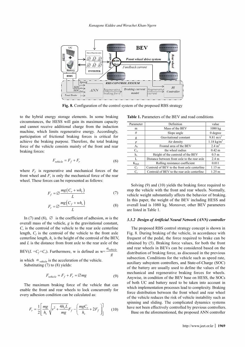
BEV Fig. 8 show configuration of the control strategy of the
proposed RBS strategy. The ANNs, PI controller and the braking force distribution are the main part, which are discussed in subsections as given by:
3.3.1 Braking force distribution of the BEV
In braking condition, braking energy will be transferred
Fig. 6. The equivalent circuit of the proposed HESS, three phase inverter and three-phase BLDC motor
(a) (b)
Fig. 7. Waveforms of the back-EMFs, the armature currents and the switching scheme: (a) normal operational mode, (b) regenerative braking mod
Kunagone Kiddee and Werachet Khan-Ngern
http://www.jeet.or.kr │ 1969
to the hybrid energy storage elements. In some braking circumstances, the HESS will gain its maximum capacity and cannot receive additional charge from the induction machine, which limits regenerative energy. Accordingly, participation of frictional braking forces is critical for achieve the braking purpose. Therefore, the total braking force of the vehicle consists mainly of the front and rear braking forces:
vehicle f rF F F= + (6)
where Ff is regenerative and mechanical forces of the front wheel and Fr is only the mechanical force of the rear wheel. These forces can be represented as follows:
( ) r v
fmg C wh
FL+
= Æ (7)
( ) f v
r
mg C whF
L
+= Æ (8)
In (7) and (8), Æ is the coefficient of adhesion, m is the
overall mass of the vehicle, g is the gravitational constant, Cr is the centroid of the vehicle to the rear axle centerline length, Cf is the centroid of the vehicle to the front axle centerline length, hv is the height of the centroid of the BEV, and L is the distance from front axle to the rear axle of the
BEV(L =Cf +Cr). Furthermore, w is defined as w= vehicleαg
in which α vehicle is the acceleration of the vehicle. Substituting (7) to (8) yields:
vehicle f rF F F mg= + = Æ (9) The maximum braking force of the vehicle that can
enable the front and rear wheels to lock concurrently for every adhesion condition can be calculated as:
2 41 22
v rr f f
v v
h L mgCmgF v F Fh mg h
é ùæ ö= + - +ê úç ÷
ê úè øë û (10)
Solving (9) and (10) yields the braking force required to stop the vehicle with the front and rear wheels. Normally, vehicle weight substantially affects the behavior of braking. In this paper, the weight of the BEV including HESS and overall load is 1080 kg. Moreover, other BEV parameters are listed in Table 1.
3.3.2 Design of Artificial Neural Network (ANN) controller
The proposed RBS control strategy concept is shown in
Fig. 8. During braking of the vehicle, in accordance with frequent of the pedal, the force required to brake can be obtained by (5). Braking force values, for both the front and rear wheels in BEVs can be considered based on the distribution of braking force, as discussed in the previous subsection. Conditions for the vehicle such as speed rate, auxiliary subsystem controllers, and State-of-Charge (SOC) of the battery are usually used to define the values of the mechanical and regenerative braking forces for wheels. Anywise, in condition of the BEV base on HESS, the SOCs of both UC and battery need to be taken into account in which implementation processes lead to complexity. Braking force distribution between the front wheel and rear wheel of the vehicle reduces the risk of vehicle instability such as spinning and sliding. The complicated dynamics systems have not been effectively controlled by previous controllers.
Base on the aforementioned, the proposed ANN controller
Fig. 8. Configuration of the control system of the proposed RBS strategy
Table 1. Parameters of the BEV and road conditions
Parameter Definition value m Mass of the BEV 1080 kg θ Slope angle 0 degree g Gravitational constant 9.81 m/s2 ρ Air density 1.18 kg/m3 Af Frontal area of the BEV 2.4 m2 Cw the wheel radius 0.42 m hv Height of the centroid of the BEV 0.5 m L Distance between front axle to the rear axle 2.4 m
KRoll Rolling resistance coefficient 0.011 Cf Centroid of BEV to the front axle centerline 1.15 m Cr Centroid of BEV to the rear axle centerline 1.25 m

Performance Evaluation of Regenerative Braking System Based on a HESS in Extended Range BEV
1970 │ J Electr Eng Technol.2018; 13(5): 1965-1977
is utilized to distribute the required braking force between the different wheels of the BEV. ANNs are intelligent computational models based on large inter-connected com-ponents called artificial neurons, which can be defined by the association of both input and output arrays Multilayer Perceptron (MLP), which is a well-known function of ANNs.
ANN performance depends mainly on the design procedure. All possible circumstances must be prepared in a training dataset for learning by the ANN. Then, the ANN can be trained by the collected training datasets. Finally, evaluation and validation of the trained ANN scheme with other training datasets is necessary to examine infallibility in the system.
A four layer MLP neural network in various simulations provides desirable performance. The speed of vehicle, state of charge of the UC and battery and brake pedal depression are specified input of the MLP. One hidden layer with 5 neurons is considered. The mechanical braking forces of the front and rear wheels and the regenerative braking force of the front wheel are outputs of the utilized ANN. The activation function for the neurons in the hidden layers using sigmoid functions can be represented as follows:
( ) /1
1u u tfe-
=+
(11)
Fig. 9 shows the proposed MLP neuron network
configuration [27]. Association with the brake pedal depression, the braking force of front and rear wheels can be calculated using the ideal braking force distribution, which is discussed in the previous subsection. In addition to the training dataset, it should also include enough data for the mechanical braking and regenerative braking forces for various functional conditions [28-29].
The Simulink within MATLAB is utilized to establish the training dataset with different simulations by using various values for state of charge of the UC and battery. The speed of the vehicle and braking force are created by the rich training dataset of drive cycles that can be obtained from the braking situation occurring at various BEV speeds and different brake forces. The selection of the drive loop is very significant for braking simulation.
The Normalized Root Mean Square Error (NRMSE) is one of the principles used to evaluate the performance of the ANNs, which is the maximum error between the analyzed output and the real output, and can be represented
as follows:
( ) ( )
( )2n
n
F n F nNRMSE
F n
-é ùë û¢
¢=åå
(12)
where () and ′() are the estimated and goal values of the outputs respectively and n is number of data unit. In the training stage, 328 cases are simulated through various SOCs. The NRMSE is calculated 0.017, 0.011, 0.016 for the rear force, front force and regenerative-braking force respectively.
Fig. 10 shows a diagram of the simulated drivetrain consisting mainly of mechanical and electrical modules. The simulation and experimental parameters are shown in Table 2. Moreover, the specifications of the battery and UC are listed in Table 3.
3.3.3 PI Controller
When braking force distribution is achieved by the ANN,
Fig. 9. The MLP function of the ANN
Fig. 10. Configuration of drivetrain in MATLAB
Table 2. Simulation and experimental specifications
Specifications Simulation Experimental
Battery Lithium-ion Battery pack from
ADVISOR 12 Volt 20Ah 3 packs in series
Lithium-ion Battery pack 12 Volt 20Ah 3
packs in series
UC Maxwell Ultracapacitor
BoostCap 2.7V 500 Farad 18 cell in series
Ultracapacitor 2.7V 500 Farad 18 cell
in series
Motor Three-Phase BLDC Motor, 5 kW from ADVISOR
Three-Phase BLDC Motor, 5 kW from
LapVolt series Measurement
Instrument Data Acquisition and Control Interface 9063
Table 3. Specification of battery and UC
Parameter Value Unit Rated Battery voltage 36-40 V
Battery capacity 20 Ah Battery energy storage 760 Wh
Battery maximum charge/discharge current 10/20 A Rated UC voltage 48.6 V
Rated UC capacitance 27 F UC energy storage 9.12 Wh
UC maximum charge/discharge current 50/50 A
Kunagone Kiddee and Werachet Khan-Ngern
http://www.jeet.or.kr │ 1971
the front wheel braking force is converted to the regenerative braking current by (13):
regenerative brakingI k F= ´ (13)
Regenerative braking torque is regulated by the PI
controller using the PWM duty-cycle procedure. Therefore, regenerative braking constant torque is achieved by the proposed method for realizing security objectives.
3.4 The efficiency consideration of the proposed RBS
Normally, the regenerative braking efficiency of the
proposed system depends on several conditions such as the SOCs of UC and battery, the velocity of vehicle, information for drive-cycle, etc. Efficiency is given as follows:
1 1
1
Δ% 100
Δ
n nUC Batti i
nkiti
E Eμ
E= =
=
+= ´å å
å (14)
In (14), n is the number of braking processes of the
BEV in the drive-cycle. Furthermore, Δ UCE is the differentiation of energy density in the UC during braking and can be obtained with the following equation:
21Δ2UCE CV= (15)
where C is the specific capacitance of the UC and 2V is the rated voltage or potential window of the UC module during braking of the vehicle. Δ is energy density in the battery during braking according to the following relationship:
( )( )2
2
1
Δt
Batt Batt Batt battt
E V i R t i dt= -ò (16)
where R is initial internal resistance of the charging battery. VBatt and iBatt are the voltage and current of the battery, respectively. Additionally, t1 and t2 are the beginning and stopping of decelerating or braking processes. Finally, Δ is the differentiation of kinetic energy in the BEV which can be obtained as follows:
( )2 22 1
1Δ2KitE m v v= - (17)
where m is the mass of the BEV and v1 and v2 are vehicle velocities during braking.
3.5 Analysis of the system losses in the proposed
system In this study, the conduction and switching losses of the
unidirectional dc–dc converter are considered for Buck mode. The dc–dc converter conduction losses of the high-side switch is computed as
2, ,
outon H out on H
in
VP I R
V= ´ ´ (18)
The dc–dc converter conduction losses of the low-side
IGBT can be written as
2, , 1 out
on L out on Lin
VP I R
Væ ö
= ´ ´ -ç ÷è ø
(19)
where Vin is the input voltage, Vout is the output voltage. Ron,H is the high-side IGBT on resistance, Ron,L is the low-side IGBT on resistance.
The switching losses of dc–dc converter can be expressed as:
( ) 2
,
1 12 2C L r f C oss
sw loss s
charge G C rr
V I t t V CP f
Q V V Q
æ ö+ +ç ÷= ç ÷ç ÷+ +è ø
(20)
The inductor current is IL, which is equal to the UC
current Iuc. The output capacitance of the dc–dc converter is C and Vc is the voltage across. The switching frequency fs is 50 kHz. tr and tf are the rise-time and fall-time transitions of IGBTs during switching periods. Coss is the output capacitance of IGBT. Qcharge is the gate charge due to charging the gate capacitance by gate voltage. Qrr is the reverse recovery charge. VG is the gate voltage.
The reverse recovery loss in the body diode can be written as
12Diode in rr rr sP V I t f= ´ ´ ´ ´ (21)
where Irr is the peak value of body diode reverse recovery current. trr is the body diode reverse recovery time.
As regards both the electrical losses of the inverter and the motor, these can be expressed by the approximate relationship
2
, ,Inv Mot loss consP P kP= + (22)
where PInv,Mot,loss is the power of losses at power level (P). Pcons is the power of constant losses. k is the constant [W-1].
The values of parameters k, Pcons are defined by the systems losses analysis of the inverter and motor as a function of operating power. Assuming therefore that the mean power during braking is given as
Δ kit
brakebrake
EP
t= (23)

Performance Evaluation of Regenerative Braking System Based on a HESS in Extended Range BEV
1972 │ J Electr Eng Technol.2018; 13(5): 1965-1977
where ΔEkit is the kinetic energy portion converted into electric energy. tbrake is the set time of braking.
The total power losses in HESS are the sum of power losses in the dc–dc buck converter, inverter, motor, during braking and the UC/battery as
, , , ,HESS loss on H on L sw loss DiodeP P P P P= + + +
2 2. ,Inv Mot loss brake UC UC battP P I R I+ + + + (24)
Since the total power loss is obtained, the efficiency can
be calculated with the following equation
( ) ,
OUT OUT
OUT OUT HESS loss
V Iη
V I P´
=´ +
(25)
where VOUT is the output voltage. IOUT is the output current.
4. Experimental and Simulation Results The proposed regenerative braking was simulated and
modeled using Simulink within MATLAB. The New York City Cycle (NYCC) drive cycle was selected to evaluate regenerative braking performance. The length of the drive cycle for testing was 8210.28 meters using total actual driving time of 824 seconds. The maximum speed of the vehicle stretched 78.48 km/h and in driving time, the BEV spent 36.31% in decelerating mode. The entire BEV components, comprised of the BLDC motor, battery, UC, etc., were modeled as data analysis applications as well as lookup table and efficiency maps based on the empirical measurements obtained from literature, datasheets, etc. The model uses specified speeds as inputs and controls the rate power, velocity, and torque that meet the velocity of the vehicle. Table 2 show that the parameters of the HESS and RBS for the simulations and experiments
Fig. 11(a) shows speed curve of the vehicle drive-cycle. The BEV is accelerated to a constant speed. After that, it is decelerated to standstill mode again. This process is repeated two more times at a constantly increasing velocity. Consequently, the proposed HESS can be activated at all operating modes using the simulation in a virtual driving environment.
The motor torque curve of the BEV is illustrated in Fig. 11(b). In the acceleration mode of the vehicle, the required motor torque reaches approximately 154 N.m. The highlighted area is demonstrates the regenerative braking area, in which energy is transferred to the HESS. While, constant speeds are increased, the braking torque is increased, that clearly illustrating the efficient performance of the proposed ANN controller.
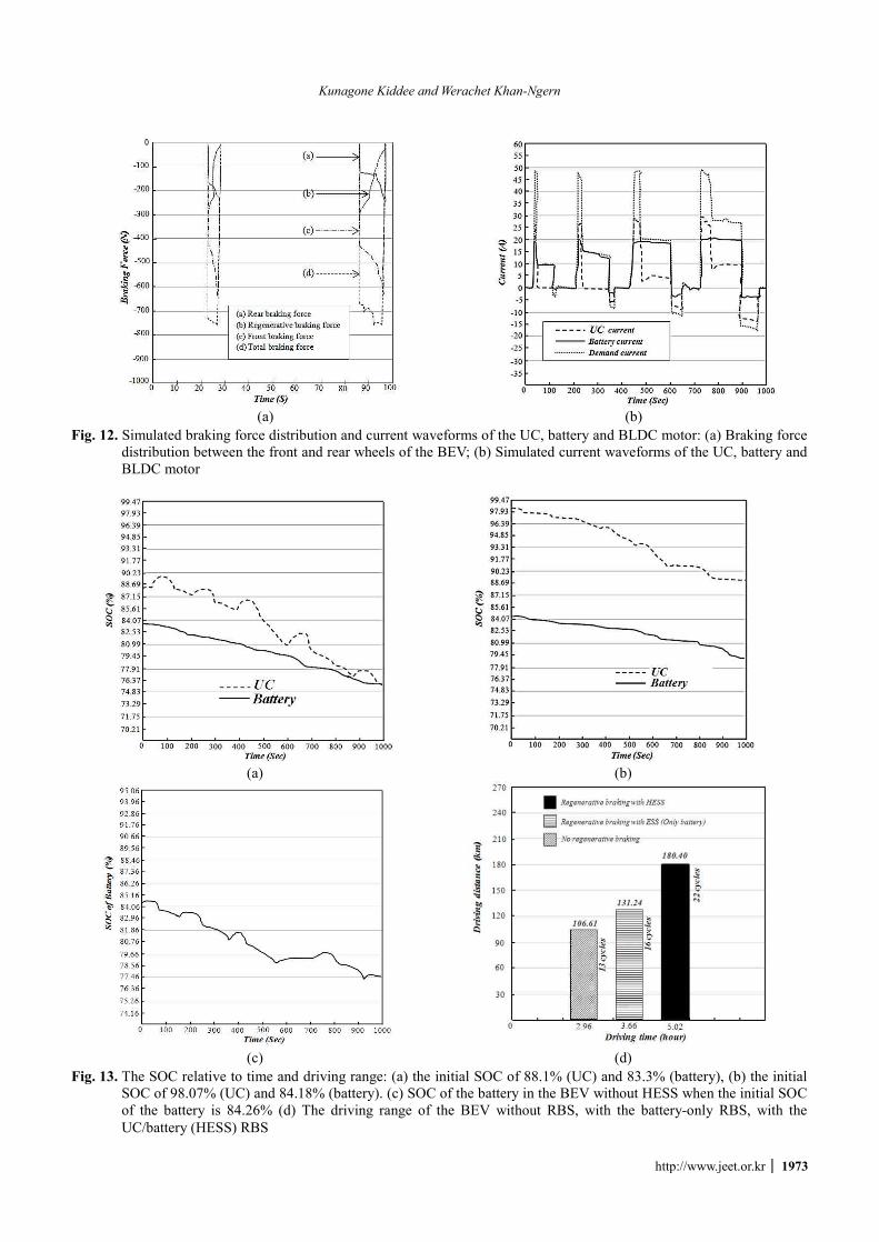
The distribution of braking force of the front, rear wheel and proportion of regenerative braking forces as well as the mechanical forces are achieved through operation in real time by the ANN controller, as illustrated in Fig. 12(a). It
can be summarize that the braking force of the front wheel is significantly larger than the braking force of the rear wheel. Furthermore, regenerative braking proportion is increased at further constant speeds of the vehicle. In addition, regenerative braking will be considerably lower via the ANN controller at low vehicle speeds and shares to braking force for stability deceleration of the BEV.
In acceleration mode of the vehicle is shown in Fig. 11 (b). The BLDC motor is required a high transient torque. Hence, a large transient current will be drawn from the HESS element, which can substantially degrade battery life. As shown in Fig. 12(b), the UC module assists the battery pack during acceleration mode and high power mode of the BEV. When the battery discharge current reaches the maximum value of 20 A, the UC module will be provide the rest of the current demand by regulating PWM in the power converter. Moreover, it can be concluded that the large current of regenerative braking is harvested through
(a)
(b)
Fig. 11. (a) Simulated speed curves of the proposed RBS in NYCC drive cycle; (b) Motor-Generator torque curve of the proposed RBS
Kunagone Kiddee and Werachet Khan-Ngern
http://www.jeet.or.kr │ 1973
(a) (b)
Fig. 12. Simulated braking force distribution and current waveforms of the UC, battery and BLDC motor: (a) Braking force distribution between the front and rear wheels of the BEV; (b) Simulated current waveforms of the UC, battery and BLDC motor
(a) (b)
(c) (d)
Fig. 13. The SOC relative to time and driving range: (a) the initial SOC of 88.1% (UC) and 83.3% (battery), (b) the initial SOC of 98.07% (UC) and 84.18% (battery). (c) SOC of the battery in the BEV without HESS when the initial SOC of the battery is 84.26% (d) The driving range of the BEV without RBS, with the battery-only RBS, with the UC/battery (HESS) RBS

Performance Evaluation of Regenerative Braking System Based on a HESS in Extended Range BEV
1974 │ J Electr Eng Technol.2018; 13(5): 1965-1977
the UC module, which not only increases braking efficiency, but also maintains the battery from large currents of charging.
The efficiency of the proposed scheme can be estimated using the state of charge of the HESS during the drive-cycle. Fig. 13(a) shows the initial SOC of the UC and the battery. In the first circumstance, the SOC of the UC and battery are set to 88.1% and 83.3%, respectively. Con-sequently, UC voltage is much lower than the maximum safety zone (95%). Accordingly, braking energy is harvested by only the UC. In the second circumstance, the state of charge of the UC reaches 98.07%, as shown in Fig. 13(b). Consequently, the SOC of the UC is over the safety threshold. Hence, braking energy cannot be harvested through the UC. Therefore, regenerative braking is harvested through the battery by regulating the DC-link voltage. Fig. 13(c) shows the battery SOCs in case the vehicle is driven with only the battery.
For the two conditions mentioned above, where the SOCs of the UC are 88.1% and 98.07%, efficiency is calculated at 49.2% and 45.4%, respectively. In the second case, the battery is used for regenerative braking since the UC voltage is beyond the safety threshold during the braking circumstances. Since the battery maximum charge current is limited, heat of the braking energy will be transferred through frictional braking. Hence, the efficiency of regenerative braking is decreased 3.8%, according to (14). In case the BEV is driven with only the battery (ESS), efficiency is decreased about 27% compared to case 1 (Regenerative braking with UC).
Moreover, the power loss evaluation of the regenerative braking with battery of the proposed HESS (Fig. 13b) is analyzed and compared with the regenerative braking with only the battery (the BEV driven with only the battery). Since the conduction loss is increased, the power loss of the regenerative braking with battery of the proposed HESS is increased by 9.83 W compared to the regenerative braking with only the battery (the BEV driven with only the battery).
In the case of the proposed system, the result shows the UC assists the battery pack during BEV acceleration and high speeds, as seen in Fig. 13(a) and 13(b), respectively. After arriving of the battery maximum discharge current, the UC supplies the rest of the load demand. Moreover, a large braking energy is harvested by the UC module (Fig. 11 (b)), which not only improves the braking efficiency, but also protects the battery from deep discharge. Since the braking current could be effectively stored, the BEV driving range can be significantly increased with compared to the BEV driven with only the battery (ESS), In Fig. 13(c), shows the SOC of the battery during the BEV is driven with only the battery.
The drive range of the BEV is computed more intuitive to estimate the performance of the RBS. The initial SOCs of the UC and the battery are selected 99% and 97%, respectively and the result is shown in Fig. 13(d).
Fig. 14. Test bench of the proposed RBS strategy
Fig.13(d) shows the drive range is about 13 cycles in
case of the BEV driven with only the battery (ESS) and driving cycle pattern is shown in Fig. 11(a), which a distance per cycle approximately 8.2 kilometers. Accordingly, it can be seen that the purposed HESS and the RBS strategy are improved the drive range of the BEV approximately 74 kilometers. Moreover, the drive range can increase approxi-mately 49 kilometers compared with the regenerative braking with ESS.
The proposed RBS strategy was tested in the laboratory in order to perform an evaluation. The laboratory and equipment configurations for testing of the proposed RBS strategy are shown in Fig. 14. The battery module is an EP-2415F lithium ion battery module rated at 12 Volt 20Ah 3 packs in series and weight about 6.8 kg. The BoostCap ultracapacitor is rated at 2.7V, 500 Farad from Maxwell Technologies are connected in 18 cells in series and weight about 1.3 kg. The unidirectional dc/dc buck converter is rated at 1.25 kW and is used to interface the UC module and battery pack. The motor controller is rated at 24–120 v, 600 A from VEC300 model. The BLDC motor is rated at 48-120 vdc, 3000-5000 rpm 5 kW from LapVolt series. The Data Acquisition and Control Interface 9063 are used to record the electrical characteristics data. The specifications of the UC and battery are presented in Table 3.
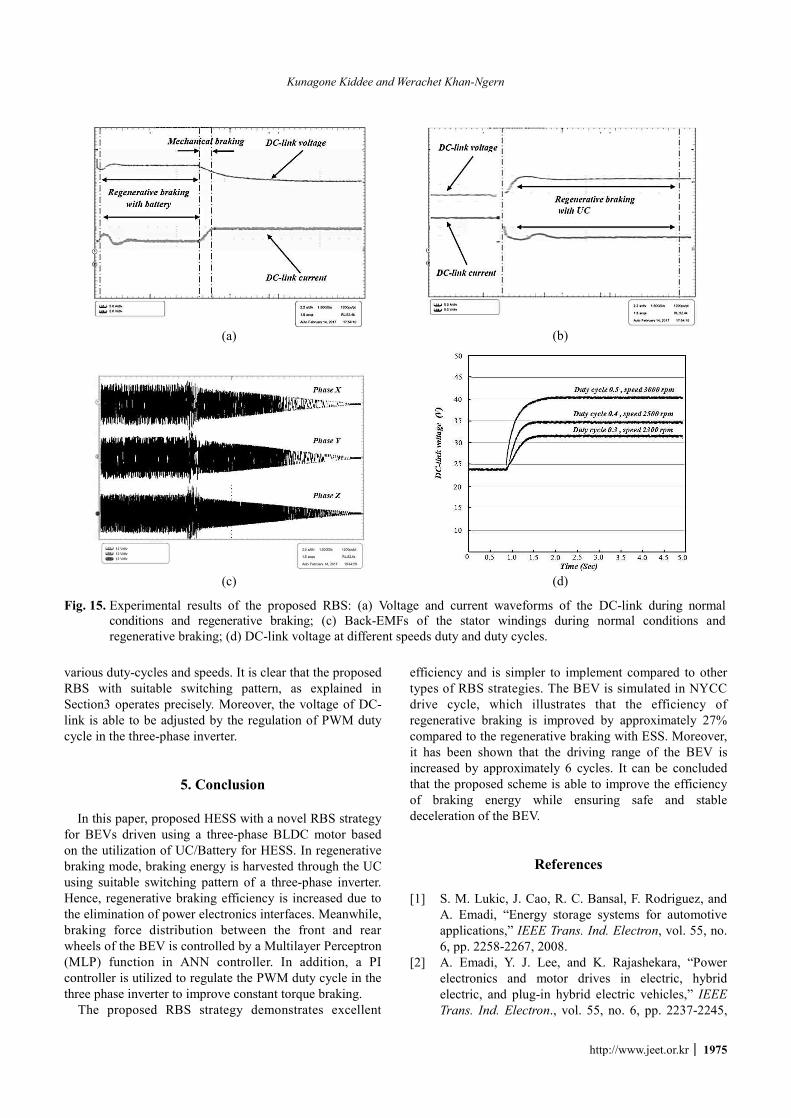
Fig.15 shows waveforms of the current and voltage of DC-link, battery current, UC current and Back EMF waveform, which generated in stator winding during braking mode. When the brake pedal is engaged, the controller will regulate the voltage of DC-link for constant torque braking with the UC. In this time duration, most of the current of DC-link is transferred to the UC and the current of battery is zero. After the voltage of the UC is beyond the maximum safety threshold, the controller will regulate the voltage of the DC-link for constant torque braking by battery. In this case, the voltage of DC-link is lower than the voltage of the UC and D3 is reverse biased. Therefore, the current of UC is relatively zero. The current of DC-link is charging with the battery pack.
During the braking process, the Back-EMFs begin to decrease. The system switches to frictional braking by the controller. Fig. 15(d) shows the voltage of DC-link at
Kunagone Kiddee and Werachet Khan-Ngern
http://www.jeet.or.kr │ 1975
various duty-cycles and speeds. It is clear that the proposed RBS with suitable switching pattern, as explained in Section3 operates precisely. Moreover, the voltage of DC-link is able to be adjusted by the regulation of PWM duty cycle in the three-phase inverter.
5. Conclusion In this paper, proposed HESS with a novel RBS strategy
for BEVs driven using a three-phase BLDC motor based on the utilization of UC/Battery for HESS. In regenerative braking mode, braking energy is harvested through the UC using suitable switching pattern of a three-phase inverter. Hence, regenerative braking efficiency is increased due to the elimination of power electronics interfaces. Meanwhile, braking force distribution between the front and rear wheels of the BEV is controlled by a Multilayer Perceptron (MLP) function in ANN controller. In addition, a PI controller is utilized to regulate the PWM duty cycle in the three phase inverter to improve constant torque braking.
The proposed RBS strategy demonstrates excellent
efficiency and is simpler to implement compared to other types of RBS strategies. The BEV is simulated in NYCC drive cycle, which illustrates that the efficiency of regenerative braking is improved by approximately 27% compared to the regenerative braking with ESS. Moreover, it has been shown that the driving range of the BEV is increased by approximately 6 cycles. It can be concluded that the proposed scheme is able to improve the efficiency of braking energy while ensuring safe and stable deceleration of the BEV.
References
[1] S. M. Lukic, J. Cao, R. C. Bansal, F. Rodriguez, and A. Emadi, “Energy storage systems for automotive applications,” IEEE Trans. Ind. Electron, vol. 55, no. 6, pp. 2258-2267, 2008.
[2] A. Emadi, Y. J. Lee, and K. Rajashekara, “Power electronics and motor drives in electric, hybrid electric, and plug-in hybrid electric vehicles,” IEEE Trans. Ind. Electron., vol. 55, no. 6, pp. 2237-2245,
(a)
(b)
(c)
(d)
Fig. 15. Experimental results of the proposed RBS: (a) Voltage and current waveforms of the DC-link during normal conditions and regenerative braking; (c) Back-EMFs of the stator windings during normal conditions and regenerative braking; (d) DC-link voltage at different speeds duty and duty cycles.
Performance Evaluation of Regenerative Braking System Based on a HESS in Extended Range BEV
1976 │ J Electr Eng Technol.2018; 13(5): 1965-1977
2008. [3] K. Jonghoon, S. Jongwon, C. Changyoon, and B. H.
Cho, “Stable configuration of a Li-Ion series battery pack based on a screening process for improved voltage/SOC balancing,” IEEE Trans. Power Electron., vol. 27, no. 1, pp. 411-424, 2012.
[4] Y. Kim, and N. Chang, ‘‘Design and management of energy-efficient hybrid electric energy storage systems,’’ springer, pp.19-25, 2014.
[5] H. Yin, C. Zhao, M. Li and et al., “Utility function-based real-time control of A battery ultracapacitor hybrid energy system,” IEEE Trans. Ind. Inf., vol. 11, no. 1, pp. 220-231, 2015.
[6] P. J. Grbović, P. Delarue, P. Le Moigne and P. Bartholomeus, “A bidirectional three-level DC-DC converter for the ultracapacitor applications,” IEEE Trans. Ind. Electron., vol. 57, no. 10, pp. 3415-3430, Oct. 2010.
[7] M. T. E. Heinrich, F. Kelch, P. Magne, and A. Emadi, “Regenerative braking capability analysis of an electric taxiing system for a single aisle midsize aircraft,” IEEE Trans. Transport. Electrific., vol. 1, no. 3, pp. 298-307, Oct. 2015.
[8] M.-E. Choi, J.-S. Lee and S.-W. Seo, “Real-time optimization for power management systems of a battery/supercapacitor hybrid energy storage system in electric vehicles,” IEEE Trans. Veh. Technol., vol. 63, no. 8, pp. 3600-3611, Oct. 2014.
[9] J. Cao, and A. Emadi, ‘‘A new battery/ultracapacitor hybrid energy storage system for electric, hybrid, and plug-in hybrid electric vehicles,’’ IEEE Trans. Power Electron., vol. 27, no. 1, pp. 122-132, 2011.
[10] K. Chol-Ho, K. Moon-Young, and M. Gun-Woo, “A modularized charge equalizer using a battery moni-toring IC for series-connected Li-Ion battery strings in electric vehicles,” IEEE Trans. Power Electron., vol. 28, no. 8, pp. 3779-3787, 2013.
[11] J. Shen and A. Khaligh, “A supervisory energy management control strategy in a battery/ultracapacitor hybrid energy storage system,” IEEE Trans. Transport. Electrific. vol. 1, no. 3, pp. 223-231, Oct. 2015.
[12] A. Kuperman, I. Aharon, S. Malki and A. Kara, “Design of a semiactive battery-ultracapacitor hybrid energy source,” IEEE Trans. Power Electron., vol. 28, no. 2, pp. 806-815, Feb. 2013.
[13] N.R. Tummuru, S. Member, M.K. Mishra and et al., “Dynamic energy management of renewable grid integrated hybrid energy storage system,” Dyn. Energy Manag. Renew. Grid Integr. Hybrid Energy Storage Syst., vol. 62, no. 12, pp. 7728-7737, 2015.
[14] S. Dusmez, A. Hasanzadeh and A. Khaligh, “Com-parative analysis of bidirectional three-level DC-DC converter for automotive applications,” IEEE Trans. Ind. Electron., vol. 62, no. 5, pp. 3305-3315, 2015.
[15] T. Mesbahi, N. Rizoug, F. Khenfri, P. Bartholomeüs and P. Le Moigne, “Dynamical modelling and
emulation of Li-ion batteries-supercapacitors hybrid power supply for electric vehicle applications,” IET Electr. Syst. Transp., vol. 7, pp. 161-169, Nov. 2016.
[16] A. Castaings, W. Lhomme, R. Trigui and A. Bouscayrol, “Comparison of energy management strategies of a battery/supercapacitors system for electric vehicle under real-time constraints,” Appl. Energy, vol. 163, pp. 190-200, 2016.
[17] R. E. Araujo, R. de Castro, C. Pinto, P. Melo and D. Freitas, “Combined sizing and energy management in EVs with batteries and supercapacitors,” IEEE Trans. Veh. Technol., vol. 63, no. 7, pp. 3062-3076, Sep. 2014.
[18] S. K. Kollimalla, M. K. Mishra and N. L. Narasamma, “Design and analysis of novel control strategy for battery and supercapacitor storage system,” IEEE Trans. Sustain. Energy, vol. 5, no. 4, pp. 1137-1144, Oct. 2014.
[19] Z. Chen, R. Xiong, K. Wang and B. Jiao, “Optimal energy management strategy of a plug-in hybrid electric vehicle based on a particle swarm optimiza-tion algorithm,” Energies, vol. 8, no. 5, pp. 3661-3678, 2015.
[20] J. L. Torres, R. Gonzalez, A. Gimenez and J. Lopez, “Energy management strategy for plug-in hybrid electric vehicles. A comparative study,” Appl. Energy, vol. 113, pp. 816-824, Jan. 2014.
[21] T. Mesbahi, F. Khenfri, N. Rizoug, P. Bartholomeus and P. Le Moigne, “Combined optimal sizing and control of Li-Ion battery/supercapacitor embedded power supply using hybrid particle swarm-Nelder-Mead algorithm,” IEEE Trans. Sustain. Energy, vol. 8, no. 1, pp. 59-73, Jan. 2017.
[22] J. O. Estima and A. J. M. Cardoso, “Efficiency analysis of drive train topologies applied to electric/ hybrid vehicles,” IEEE Trans. Veh. Technol., vol. 61, no. 3, pp. 1021-1031, Mar. 2012.
[23] F. Odeim, J. Roes and A. Heinzel, “Power manage-ment optimization of an experimental fuel cell/ battery/supercapacitor hybrid system,” Energies 2015, vol. 8, pp. 6302-6327, Mar. 2015.
[24] R. Hoseinnezhad and A. Bab-Hadiashar, “Efficient antilock braking by direct maximization of tire-road frictions,” IEEE Trans. Ind. Electron., vol. 58, no. 8, pp. 3593-3600, Aug. 2011.
[25] A. V. Topalov, Y. Oniz, E. Kayacan and O. Kaynak, “Neuro-fuzzy control of antilock braking system using sliding mode incremental learning algorithm,” Neurocomputing, vol. 74, no. 11, pp. 1883-1893, May 2011.
[26] J. Ko, S. Ko, I. Kim, D. Hyun and H. Kim, “Co-operative control for regenerative braking and friction braking to increase energy recovery without wheel lock,” Int. J. Autom. Technol., vol. 15, no. 2, pp. 253-262, Mar. 2014.
[27] G. Hongwei, G. Yimin, and M. Ehsani, ‘‘A neural

Kunagone Kiddee and Werachet Khan-Ngern
http://www.jeet.or.kr │ 1977
network based SRM drive control strategy for regenerative braking in EV and HEV,’’ Electric Machines and Drives Conference, pp. 571-575, June 2001.
[28] J. Ko, S. Ko, H. Son, B. Yoo, J. Cheon and H. Kim, ‘‘Development of Brake System and Regenerative Braking Cooperative Control Algorithm for Automatic-Transmission-Based Hybrid Electric Vehicles,’’ IEEE Trans. Veh. Technol., vol. 64, no. 2, pp. 431-440, May 2014.
[29] N. Mutoh, ‘‘Driving and braking torque distribution methods for front-and rear-wheel-independent drive-type electric vehicles on roads with low friction coefficient,’’ IEEE Trans. Ind. Electron., vol. 59, no. 10, pp. 3919-3933, Feb. 2012.
Kunagone Kiddee He received the B.Eng degree in electronics enginee-ring from King Mongkut’s Institute of Technology Ladkrabang in 2013. Currently, he is pursuing the Ph.D. degree in electrical engineering in King Mongkut’s Institute of Technology Ladkrabang. His research interests
include power electronics, electric vehicle systems, intelligent control, and electrical machines.
Werachet Khan-Ngern He received B.Eng and M.Eng in electrical engin-eering from King Mongkut’s Institute of Technology Ladkrabang (KMITL), Thailand and received his Ph.D. and DIC in electrical engineering (power electronics) from Imperial College of Science Technology and Medicine,
University of London in 1997. He is currently an associate professor at electrical engineering department, KMITL, Thailand. His research areas are focused on electromag-netic compatibility, converters, inverters, energy storage and green energy applications. His recently research is focused on zero emission vehicle from proton exchange membrane fuel cell EVs, lithium phosphate battery application in EVs, amphibious EVs, wireless power charging for EVs, design of maximum power point tracking for PV system and the design of high performance electric car using carbon nano tube (CNT) material to meet a high EV energy saving.
Related Documents


![REGENERATIVE BRAKING SYSTEM IN ELECTRIC VEHICLES · REGENERATIVE BRAKING SYSTEM IN ELECTRIC VEHICLES ... REGENERATIVE BRAKING SYSTEM ... Regenerative action during braking[9].](https://static.cupdf.com/doc/110x72/5adccef67f8b9a1a088c7cf0/regenerative-braking-system-in-electric-vehicles-braking-system-in-electric-vehicles.jpg)