1 Performance Evaluation of Refrigeration units in Natural Gas Liquid Extraction Plant Dirina Amesi and Awajiogak Anthony Ujile * Department of Chemical/Petrochemical Engineering, Faculty of Engineering, Rivers State University of Science and Technology, PMB 5080, Port Harcourt. Nigeria * Corresponding author: Email: [email protected] ; [email protected]; Tel: +2348033398876 Abstract This paper has applied thermodynamics principles to evaluate the reliability of 390m 3 /hr natural gas processing plant. The thermodynamics equations were utilized in the evaluation, characterization and numerical simulation of key process parameters in natural gas liquid extraction plant. The results obtained show the comparison of the coefficient of performance, compression ratio, isentropic work, actual work, electrical power requirements, cooling water consumption in intercoolers, compressor power output, compressor capacity, isentropic, volumetric and mechanical efficiency of the two-stage refrigeration unit with a flash gas economizer and these were compared with the designed specifications. The second law of thermodynamics was applied in analyzing the refrigeration unit and the result shows that exergetic losses or lost work due to irreversibility falls within operating limit that is less than 1.0%. Similarly, the performance of expansion turbine (expander) parameters were monitored and the results indicate a considerable decrease in turbine efficiencies as the inlet gas pressure increases resulting in an increased power output of the turbine leading to a higher liquefaction rate. Introduction The production and availability of natural gas liquid depends largely on the supply of raw natural gas from production wellhead and the operating conditions of the process unit that make up the extraction plant. Most gas processing plants are faced with problems ranging from inadequate supply, poor facility performance and human factors. These problems can lead to low productivity of natural gas liquids and reduction in gas quality which could result to shutting down of the plant. Poor facility such as inadequate electricity supply and processed water supply used in process equipment also lead to intermittent operations, malfunction of process equipment such as pumps, compressors, valves if they are not adequately checked. Human factors may also result from the inability of gas plant operators to monitor thermodynamics parameters such as the pressure, flow-rates and temperature on process equipment which could result in loss of data in control room, unintended activation or deactivation of process devices and reduce the plant efficiency. In spite of the fact that these thermodynamics parameters are monitored daily in a gas plant, there are problems of low gas feed inlet pressure and insufficient gas flow rate. These have resulted in low volume of natural gas liquids produced, the extracted natural gas liquids not attaining the expected cryogenic temperature requirement and variation in gas quality discharging from the outlet of natural gas liquid extraction unit bottom product. If the available inlet gas pressure is low, it can result in compressor system suction pressure falling below atmospheric pressure. This can also lead to air leakages into the compressor system, contributing to pulsation, corrosion and low heating value of natural gas. In order to solve these problems, performance evaluation of the process units in natural gas liquids extraction using thermodynamics principles is necessary to ensure that these problems are minimized. It is seen from literature survey that several papers have been published focusing on thermodynamic analysis of a gas turbine power plant.

Welcome message from author
This document is posted to help you gain knowledge. Please leave a comment to let me know what you think about it! Share it to your friends and learn new things together.
Transcript

1
Performance Evaluation of Refrigeration units in Natural Gas
Liquid Extraction Plant
Dirina Amesi and Awajiogak Anthony Ujile*
Department of Chemical/Petrochemical Engineering, Faculty of Engineering, Rivers State
University of Science and Technology, PMB 5080, Port Harcourt. Nigeria *
Corresponding author: Email: [email protected]; [email protected]; Tel: +2348033398876
Abstract This paper has applied thermodynamics principles to evaluate the reliability of 390m
3/hr natural gas processing
plant. The thermodynamics equations were utilized in the evaluation, characterization and numerical simulation of
key process parameters in natural gas liquid extraction plant. The results obtained show the comparison of the
coefficient of performance, compression ratio, isentropic work, actual work, electrical power requirements, cooling
water consumption in intercoolers, compressor power output, compressor capacity, isentropic, volumetric and
mechanical efficiency of the two-stage refrigeration unit with a flash gas economizer and these were compared with
the designed specifications. The second law of thermodynamics was applied in analyzing the refrigeration unit and
the result shows that exergetic losses or lost work due to irreversibility falls within operating limit that is less than
1.0%. Similarly, the performance of expansion turbine (expander) parameters were monitored and the results
indicate a considerable decrease in turbine efficiencies as the inlet gas pressure increases resulting in an increased
power output of the turbine leading to a higher liquefaction rate.
Introduction
The production and availability of natural gas liquid depends largely on the supply of raw natural
gas from production wellhead and the operating conditions of the process unit that make up the
extraction plant. Most gas processing plants are faced with problems ranging from inadequate
supply, poor facility performance and human factors. These problems can lead to low
productivity of natural gas liquids and reduction in gas quality which could result to shutting
down of the plant. Poor facility such as inadequate electricity supply and processed water supply
used in process equipment also lead to intermittent operations, malfunction of process equipment
such as pumps, compressors, valves if they are not adequately checked.
Human factors may also result from the inability of gas plant operators to monitor
thermodynamics parameters such as the pressure, flow-rates and temperature on process
equipment which could result in loss of data in control room, unintended activation or
deactivation of process devices and reduce the plant efficiency. In spite of the fact that these
thermodynamics parameters are monitored daily in a gas plant, there are problems of low gas
feed inlet pressure and insufficient gas flow rate. These have resulted in low volume of natural
gas liquids produced, the extracted natural gas liquids not attaining the expected cryogenic
temperature requirement and variation in gas quality discharging from the outlet of natural gas
liquid extraction unit bottom product.
If the available inlet gas pressure is low, it can result in compressor system suction pressure
falling below atmospheric pressure. This can also lead to air leakages into the compressor
system, contributing to pulsation, corrosion and low heating value of natural gas. In order to
solve these problems, performance evaluation of the process units in natural gas liquids
extraction using thermodynamics principles is necessary to ensure that these problems are
minimized.
It is seen from literature survey that several papers have been published focusing on
thermodynamic analysis of a gas turbine power plant.

2
Rahman et al., [1], Taniquchi and Miyamae [2] carried out the study on the effects of ambient
temperature, ambient pressure as well as temperature of exhaust gases on performance of gas
turbine. Khaliq and Kaushik [3] studied the efficiency of a gas turbine Cogeneration system with
heat recovery steam generator.
Keith and Kenneth [4] developed a new method of applying overall plant material balance
equation to determine the performance of a natural gas processing plant. Jibril et al., [5] studied
the simulation of expansion turbine (expander) for recovery of natural gas liquids from natural
gas stream gas using HYPRO TECH’s HYSYS process simulation software. Donnelly et al., [6]
carried out researches on process simulation and optimization of cryogenic operations using
multi-stream brazed aluminum heat exchangers. Ganapathy et al., [7] studied the energy analysis
of operating lignite fired thermal power plant. Design methodology for parametric study and
thermodynamic performance evaluation of natural gas process plant has been developed.
Refrigeration unit and Expansion turbine unit which are the major components of the plant were
evaluated. The expansion of natural gas through an expansion turbine with efficiencies shows a
very good performance Ujile and Alawa [8]. The comparison between the energy losses and the
energy losses of the components unit were investigated.
This paper examined the reliability of a gas plant which is the ability of a plant to maintain a
stable efficiency with respect to time using thermodynamics equations.
METHODOLOGY/SYSTEM DESCRIPTIONS
(a) Propane refrigeration unit:
The simulation of process units in propane refrigeration cycle involves the applications of
thermodynamics principles to:
(i) Calculate the amount of heat added to or removed from process streams.
(ii) Estimate the power requirements for process equipment such as pumps, compressors
and turbine.
(iii) Evaluate the performance of a flash separator at various temperature and pressure.
(v) Determining the bubble and dew point temperature associated with distillation and
bottom products.
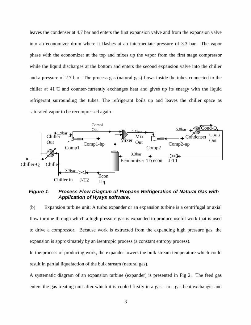
A systematic diagram of propane refrigeration cycle is shown in Fig. 1. The refrigerant passes
through the scrubber into the first stage compressor at 1.9 bar as saturated vapor where it mixes
up with the vapor from the economizer unit. It is compressed to the inlet of the second stage
compressor at 2.5 bar and discharges at 5.0 bar into the condenser as superheated vapor. It
3
Economizer To econ J-T1
Econ
Liq
J-T2 Chiller in
Chiller-Q Chiller
Chiller
Out Comp1
Comp1-hp Mixer
Mix
Out Comp2
Comp2-hp
Condenser Cond
Out
Comp1
Out Cond-Q 1.9bar 2.5bar
5.0bar
3.3bar
2.7bar
leaves the condenser at 4.7 bar and enters the first expansion valve and from the expansion valve
into an economizer drum where it flashes at an intermediate pressure of 3.3 bar. The vapor
phase with the economizer at the top and mixes up the vapor from the first stage compressor
while the liquid discharges at the bottom and enters the second expansion valve into the chiller
and a pressure of 2.7 bar. The process gas (natural gas) flows inside the tubes connected to the
chiller at 41oC and counter-currently exchanges heat and gives up its energy with the liquid
refrigerant surrounding the tubes. The refrigerant boils up and leaves the chiller space as
saturated vapor to be recompressed again.
(b) Expansion turbine unit: A turbo expander or an expansion turbine is a centrifugal or axial
flow turbine through which a high pressure gas is expanded to produce useful work that is used
to drive a compressor. Because work is extracted from the expanding high pressure gas, the
expansion is approximately by an isentropic process (a constant entropy process).
In the process of producing work, the expander lowers the bulk stream temperature which could
result in partial liquefaction of the bulk stream (natural gas).
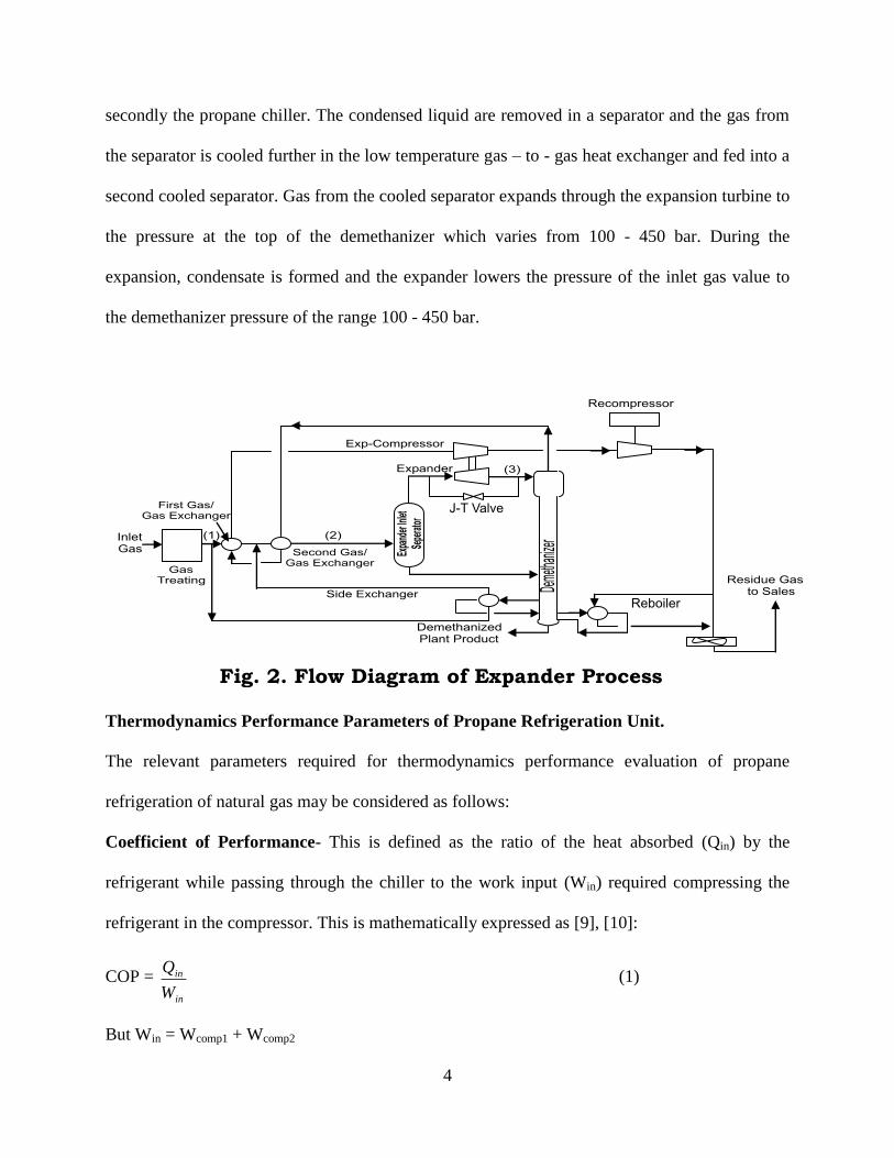
A systematic diagram of an expansion turbine (expander) is presented in Fig 2. The feed gas
enters the gas treating unit after which it is cooled firstly in a gas - to - gas heat exchanger and
Figure 1: Process Flow Diagram of Propane Refrigeration of Natural Gas with Application of Hysys software.
4
secondly the propane chiller. The condensed liquid are removed in a separator and the gas from
the separator is cooled further in the low temperature gas – to - gas heat exchanger and fed into a
second cooled separator. Gas from the cooled separator expands through the expansion turbine to
the pressure at the top of the demethanizer which varies from 100 - 450 bar. During the
expansion, condensate is formed and the expander lowers the pressure of the inlet gas value to
the demethanizer pressure of the range 100 - 450 bar.
Thermodynamics Performance Parameters of Propane Refrigeration Unit.
The relevant parameters required for thermodynamics performance evaluation of propane
refrigeration of natural gas may be considered as follows:
Coefficient of Performance- This is defined as the ratio of the heat absorbed (Qin) by the
refrigerant while passing through the chiller to the work input (Win) required compressing the
refrigerant in the compressor. This is mathematically expressed as [9], [10]:
COP =
in
in
W
Q (1)
But Win = Wcomp1 + Wcomp2
Fig. 2. Flow Diagram of Expander Process

5
= (1-XG)(HB - HA) + MC(HE – HD,MIX) (2)
MIXDECABG
IACG
HHMHHX
HHMXCOP
,1
1
(3)
Refrigeration Capacity – The refrigeration Capacity determines the rate of circulation of the
refrigerant which in turn, determines the design and size of the various units such as condenser,
compressor, evaporator (chiller) and expansion valves. This is expressed by the equation:
210
IAC
c
HHMR
, KJ/min (4)
The mass flow-rate of cooling water is calculated as follows:
Mcw =TCp
Q
cw (5)
The overall performance of a compressor is affected mainly by the inlet pressure and the inter-
stage cooler efficiency.
The simulation of process units in propane refrigeration resulted to loss of energy on the system.
The second availability balance was applied to calculate the energy losses or lost work due to
irreversibility of the process. The thermodynamics equations applied on each of the process units
are as follows [10]:
Compressor unit:
LW = MC[(HA – ToSA)] – (HB – ToSB) - WE (6)
Condenser Unit:
LW = To[MC(SC – SB)] + MCwScw(out) – Scw(in) (7)
inCWoutCW
FECCW
HH
HHMM (8)
Expansion valve:
6
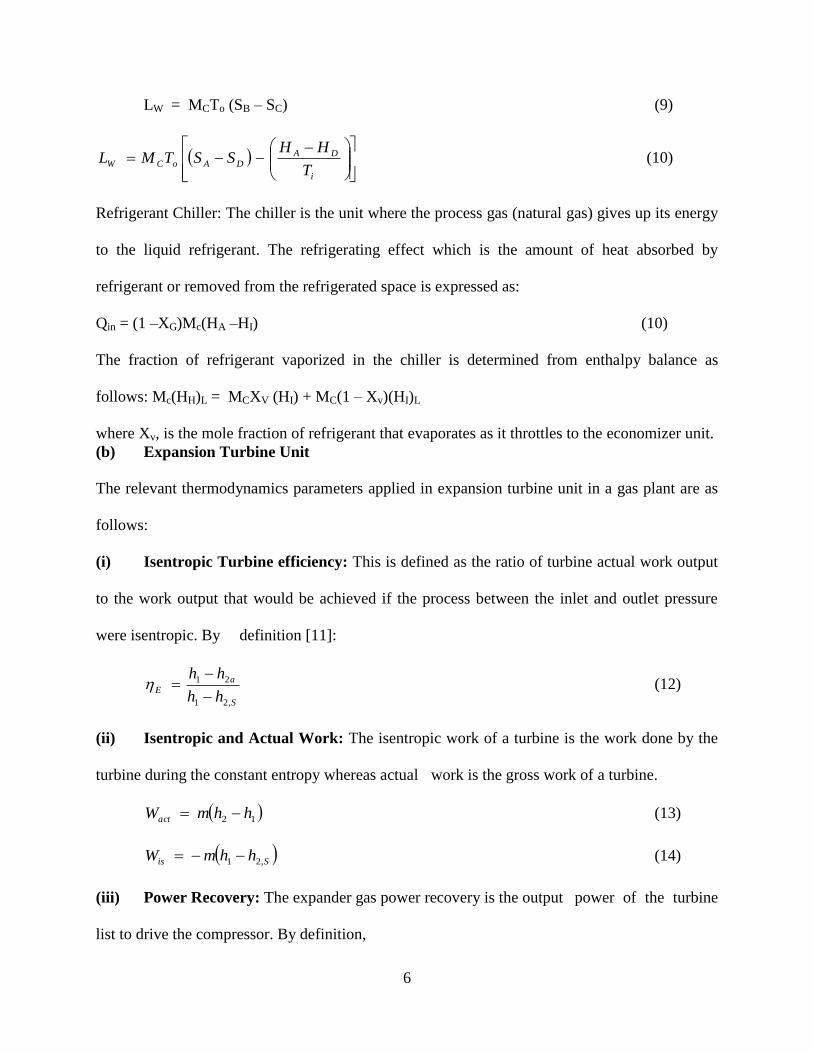
LW = MCTo (SB – SC) (9)
i
DADAoCW
T
HHSSTML (10)
Refrigerant Chiller: The chiller is the unit where the process gas (natural gas) gives up its energy
to the liquid refrigerant. The refrigerating effect which is the amount of heat absorbed by
refrigerant or removed from the refrigerated space is expressed as:
Qin = (1 –XG)Mc(HA –HI) (10)
The fraction of refrigerant vaporized in the chiller is determined from enthalpy balance as
follows: Mc(HH)L = MCXV (HI) + MC(1 – Xv)(HI)L
where Xv, is the mole fraction of refrigerant that evaporates as it throttles to the economizer unit.
(b) Expansion Turbine Unit
The relevant thermodynamics parameters applied in expansion turbine unit in a gas plant are as
follows:
(i) Isentropic Turbine efficiency: This is defined as the ratio of turbine actual work output
to the work output that would be achieved if the process between the inlet and outlet pressure
were isentropic. By definition [11]:
S
aE
hh
hh
,21
21
(12)
(ii) Isentropic and Actual Work: The isentropic work of a turbine is the work done by the
turbine during the constant entropy whereas actual work is the gross work of a turbine.
12 hhmWact (13)
Sis hhmW ,21 (14)
(iii) Power Recovery: The expander gas power recovery is the output power of the turbine
list to drive the compressor. By definition,

7
Smg hhP ,21 (15)
(iv) Theoretical and Actual Discharge Temperature: The discharge and actual
temperatures of a turbine are expressed by the equations [11], [12].:
kk
p
pTT
/)1(
1
212 '
(16)
E
KK
p
pTTT
1
)1(
1
2112 (17)
The results obtained from the evaluation with the above equations are shown in graphical form in
Figures 3 and 4.
RESULTS AND DISCUSSION
The results on the refrigeration unit of a gas plant were obtained using the P-S and T-S diagrams.
Figure 3: Pressure enthalpy diagram of a propane refrigeration cycle

8
Figure 4: Temperature entropy diagram of a propane refrigeration cycle
The two-stage compression refrigeration system in Figures 3 and 4 operates with a pressure
range of 1.9 and 5.0 bar. The refrigerant enters the first stage compressor at a suction pressure of
1.9 bar with an enthalpy and entropy value values of 2704 KJ/kg 7.145KJ/kg.K respectively. It
discharges into a mixer where it mixes up with the vapor leaving the top of the flash economizer.
The refrigerant is compressed to the second stage compressor operating with a suction pressure
of 2.5 bar; enthalpy and entropy values of 2716.4 KJ/kg; 7.052KJ/kg.K respectively, and
discharges at the condenser inlet pressure of 5.0 bar, where -17,386.7J/kg of heat is rejected to
the surrounding. The enthalpy and entropy values of the condenser as a saturated vapor at a
pressure of 4.7 bar with an enthalpy and entropy values of 630 KJ/kg and 1.8368 KJ/kg.K
respectively. The refrigerant is throttled to a flash economizer at an intermediate pressure of 3.3
bar. During flashing 0.0034 kg/s of vapor evaporate from the economizer drum while 0.1305
kg/s of liquid is throttled to the chiller at a pressure of 1.9 bar with an enthalpy and entropy
values of 575.5 KJ/kg and 1.8545 KJ/kg.K respectively. The process gas (natural gas) counter

9
currently exchanges heat and gives up its energy to the liquid refrigerant at a temperature of 41
oC. The result of the two-stage compression refrigeration is summarized in table 1.
TABLE 1: SUMMARY OF TWO – STAGE COMPRESSION REFRIGERATION
Parameters Units 1st
stage compressor 2nd
stage compressor
Suction pressure bar 1.9 2.5
Discharge pressure bar 2.5 5.0
Compression ratio - 1.316 1.414
Isentropic work of compression J/kg 20,644.25 22,094.91
Actual work of compression J/kg 20,644.25 21,872.85
Isentropic efficiency % 48.56 51.98
Mechanical efficiency % 20.71 46.51
Volumetric efficiency % 55.0 46.7
Actual power requirement KW 0.0969 0.0960
Cooling water consumption in inter-
coolers
m3/s 7.2612 19.282
Compressor capacity m3/s 2.1566 2.1096
Work input in comp 1 & comp 2 J/kg 273.14 273.14
Work output J/kg 1197.89 2414.11
The process parameters of other auxiliary units in propane refrigeration plant are shown in table
2.

10
TABLE 2: PROCESS PARAMETERS OF OTHER AUXILLIARY UNITS
Parameters unit Condenser economizer Expansion
valve 1
Expansion
valve 2
Refrigerant
chiller
Suction pressure bar 5.0 3.3 4.7 3.3 2.3
Discharge pressure bar 4.7 - 3.3 1.9 1.9
Heat load J/kg -17,386.7 5733.78 - - 17,036.04
Mass flow rate of
vapor - economizer
kg/s - 0.0034 - - -
Mass flow rate of
liquid -economizer
kg/s - 0.1305 - - -
Mass flow rate of
cooling water-
condenser
kg/s 6.72 - - - -
Joule Thompson
coefficient
- - - 8.57 12.86 -
Mole fraction of
liquid remaining in
chiller.
- 0.035 0.00014
Mole fraction of
vapor evaporated
in chiller
- 0.025 0.025 - 0.045
Mass flow rate of
liquid - condenser
accumulator
kg/s 0.1339
The energy balance of the propane refrigeration unit obtained from the evaluation based on the
equations highlighted for the analysis is shown in table 3.
TABLE 3: ENERGY BALANCE PROPANE REFRIGERATION UNIT
Process units Energy gain (KJ/kg) Energy lost (KJ/kg) % of lost work
Compressor 1 12.30 - 334.28 - 0.015
Compressor 2 32.11 - 501.45 - 0.023
Condenser - 12483.89 0.06
Expansion valve JT -1 - 12495.54 0.06

11
Expansion valve JT-2 - - 1435547.8 6.62
Economizer drum 5733.78 - -
Refrigerant chiller 17036.04 - 1242710.43 - 5.73
TOTAL 22814.23 216981.07 0.972
By the design conditions, the centrifugal compressors used in compressing the refrigerant should
operate with a pressure ratio of 1.2:1 and1.4:1, Isentropic efficiency of 70-80%; volumetric
efficiency of 60-89% and mechanical efficiency of 20-50%. By analytical method, the pressure
ratio was found to be 1.316 and 1.414; the isentropic efficiency was found to be 48.56% and
51.97%; the volumetric efficiency was found to 55.0% and 46.7% for the first and second stage
compressors respectively; while the mechanical efficiencies are 57.7% and 46.51% respectively.
The refrigeration cycle was operating with an overall coefficient of performance of 62.37 with a
refrigerating capacity of 4,922.2 tons after examining the performance of other auxiliary units
within the systems. Tables 1, 2 and 3 show values obtained from the evaluation. The Kelvin-
Planck statement of the Second Law of Thermodynamics tells us that it is impossible to have a
heat engine that will convert all the heat received from the high temperature source, QH into
useful work in a thermodynamic cycle. It is necessary to reject part of the received heat to the
low temperature source, QL. In other words: it is impossible to have a 100% efficiency heat
engine as corroborated by Kachhwaha et al [13] and Simões-Moreira [14].
Conclusion
The thermodynamics equations were applied to construct Figures 3 and 4 which determine the
performance of the plant. The recorded efficiencies range from 63.92% – 77% have shown that
the overall performance has deviated from the design efficiency. This condition may increase the
operational cost of the plant.
The following recommendations are highlighted to ensure optimum efficiency and reliability of
NGL plant.
The feed gas must be free from CO2 and water. This affects plant efficiency and
operations if not properly checked, by freezing the fittings, valves and other associated
equipment.
12
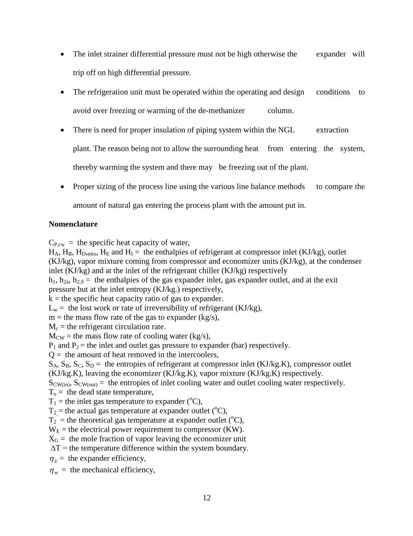
The inlet strainer differential pressure must not be high otherwise the expander will
trip off on high differential pressure.
The refrigeration unit must be operated within the operating and design conditions to
avoid over freezing or warming of the de-methanizer column.
There is need for proper insulation of piping system within the NGL extraction
plant. The reason being not to allow the surrounding heat from entering the system,
thereby warming the system and there may be freezing out of the plant.
Proper sizing of the process line using the various line balance methods to compare the
amount of natural gas entering the process plant with the amount put in.
Nomenclature
CP,cw = the specific heat capacity of water,
HA, HB, HD,mix, HE and HI = the enthalpies of refrigerant at compressor inlet (KJ/kg), outlet
(KJ/kg), vapor mixture coming from compressor and economizer units (KJ/kg), at the condenser
inlet (KJ/kg) and at the inlet of the refrigerant chiller (KJ/kg) respectively
h1, h2a, h2,S = the enthalpies of the gas expander inlet, gas expander outlet, and at the exit
pressure but at the inlet entropy (KJ/kg.) respectively,
k = the specific heat capacity ratio of gas to expander.
Lw = the lost work or rate of irreversibility of refrigerant (KJ/kg),
m = the mass flow rate of the gas to expander (kg/s),
Mc = the refrigerant circulation rate.
MCW = the mass flow rate of cooling water (kg/s),
P1 and P2 = the inlet and outlet gas pressure to expander (bar) respectively.
Q = the amount of heat removed in the intercoolers,
SA, SB, SC, SD = the entropies of refrigerant at compressor inlet (KJ/kg.K), compressor outlet
(KJ/kg.K), leaving the economizer (KJ/kg.K), vapor mixture (KJ/kg.K) respectively.
SCW(in), SCW(out) = the entropies of inlet cooling water and outlet cooling water respectively.
To = the dead state temperature,
T1 = the inlet gas temperature to expander (oC),
T2 = the actual gas temperature at expander outlet (oC),
T2’ = the theoretical gas temperature at expander outlet (
oC),
WE = the electrical power requirement to compressor (KW).
XG = the mole fraction of vapor leaving the economizer unit
∆T = the temperature difference within the system boundary.
E = the expander efficiency,
m = the mechanical efficiency,
13
References
[1] Rahman, M.M., Ibrahim, T.K., Taib M.Y, Noor M.M, Kadirgama, K and Bakar, R.A (2011).
Influence of operation conditions and ambient temperature on performance of gas turbine power
plant. Adv. Mater. Res., 189-193:3007-3013.
[2]Taniquichi H, & Miyamae S (2000). Power Generation Analysis For High Temperature Gas
Turbine in Thermodynamic Process. J. Propul. Power.16:557-561.
[3] Khaliq, A. and Kaushik, S.C (2004). Thermodynamics Performance Evaluation of
Combustion Gas Turbine Co- generation system with reheat. Appl Therm Engg. 24:1785- 1795
[4] Keith, A.B. and Kenneth, R.H (2006). “Economic Optimization Of Natural Gas Processing
Plant Including Business Aspects” Ph.D Dissertation. Texas A &M University.
[5] Jibril, K.L., AL-Humaizi, A.L., Idriss, A.A and Ibrabi, A.A (2005). Simulation Of Turbo-
Expander Processes For Recovery Of Natural Gas Liquids From Natural Gas. Saudi Aramco
Journal of Technology, 9-14.
[6] Donnelly S.T and Polasek J.C and Bullin J.A (2006). Process Simulation And Optimization
Of Cryogenic Operations Using Multi-Stream Brazed Aluminium Exchangers. Bryan Research
and Engineering, Inc. 1-12
[7] Genapathy, T., Alagumurthi N; Gakkhar, R.P and Murugesan, K. (2009). Journal of
Engineering Science and Technology Review. 2(1) 123- 130; www.jestr.org
[8] Ujile, A. A. and Alawa, L. (2012): ‘Thermodynamic evaluation of a natural gas processing
plant: Case study – Obiafu/Obrikom, Rivers State, Nigeria’. Journal of Advanced Science and
Engineering Technology Vol.2, No.1 (2012) pp. 76-80; www.ijaset.com
[9] Eastop, T. D. and McConkey (2005): Applied Thermodynamics for Engineering
Technologists. 5th
Edition. Pearson Edu.
[10] Cengel Y.A and Boles, M. A. (2002): Thermodynamics; An Engineering Approach. U.S.A.,
Fourth Edition. McGraw Hill Book Company,
[11] Stanley, I. S. (2006); Chemical, Biochemical, and Engineering Thermodynamics. Fourth
Edition. Wiley Publishers.
[12] Arora, C.P (2005): Refrigeration and Air Conditioning. Delhi India., 5th
ed., McGraw Hill
Book Company,. [13] Kachhwaha S. S., Ashok Kumar and R. S. Mishra, Thermodynamic analysis of a regenerative gas turbine
cogeneration plant, Journal of Scientific & Industrial Research, 69, 2010, 225-231.
[14] José R. and Simões-Moreira (2012): Thermal Power Plant Performance analysis.
http://www.springer.com/978-1-4471-2308-8 assessed on December 29, 2013
Related Documents