Performance Analysis of Amplify and Forward Relay during Uplink and Downlink in LTE-A Cellular Networks 1,6 Jaafar A. Aldhaibani, 2 R.B.Ahmad, 3 A.Yahya, 4 Suzan A. Azeez, 5 Ameer H. Abbas 1 School of Computer & Communication Engineering, University Malaysia Perlis (UniMAP) Kangar, Perlis, Malaysia, [email protected] 2,3 School of Computer & Communication Engineering, University Malaysia Perlis (UniMAP) Kangar, Perlis, Malaysia, 4 Ministry of Education Baghdad, Iraq 5,6 Ministry of Science & Technology, Iraq, Baghdad Abstract With the growing application for of wireless services, the capacity of 2G (2nd Generation) networks and 3G (3rd Generation) is reaching saturation point. New technologies become interest to researchers to meet with developed services, from these technologies a multi-hop relay system. This paper presents the performance analysis of amplify and forward (AF) relay network. In order to get a realistic transmission, the Signal to noise ratio (SNR) and bit rate during Uplink (UL) and Downlink (DL) transmission mode are derived in this paper. Moreover this paper discusses the impact of relay placement node to provide a maximum achievable rate at users and increase the coverage especially at cell edge regions. The numerical results shown there are enhancing in bit rate by using AF relay in comparison with direct link. Keywords: AF Relay, Half-duplex, LTE-A, SNR, Coverage 1. Introduction Long Term Evolution-advanced (LTE-A) is the successor of the 3 rd generation partnership project (3GPP) LTE in cellular networks, which is expected to enhance LTE features in terms of coverage area and throughput [1, 2]. The relay is one of the main inventions of LTE-A, which improves the cell-edge coverage throughput and increases the usage efficiency of network resources. The basic job of the relay node (RN) is that the RN amplifies received radio signals from base station (BS) or users before retransmitting to the destination rather than the base station (BS) directly sending signals to UE. The RN divides the distance between the BS and the UE into two distances: the distance from the BS to the RN, and the distance from the RN to the UE. A maximum enhancement in coverage can be achieved if the RN located in the appropriate locations and the required TX power (by the BS, RN, and UE) can be reduced [3]. Figure 1. Multi-hop relaying scenario Performance Analysis of Amplify and Forward Relay during Uplink and Downlink in LTE-A Cellular Networks Jaafar A. Aldhaibani, R.B.Ahmad, A.Yahya, Suzan A. Azeez, Ameer H. Abbas Journal of Next Generation Information Technology(JNIT) Volume 5, Number 1, February 2014 1

Welcome message from author
This document is posted to help you gain knowledge. Please leave a comment to let me know what you think about it! Share it to your friends and learn new things together.
Transcript

Performance Analysis of Amplify and Forward Relay during Uplink and Downlink in LTE-A Cellular Networks
1,6Jaafar A. Aldhaibani, 2R.B.Ahmad, 3A.Yahya, 4Suzan A. Azeez, 5Ameer H. Abbas
1 School of Computer & Communication Engineering, University Malaysia Perlis (UniMAP) Kangar, Perlis, Malaysia, [email protected]
2,3 School of Computer & Communication Engineering, University Malaysia Perlis (UniMAP) Kangar, Perlis, Malaysia,
4Ministry of Education Baghdad, Iraq
5,6Ministry of Science & Technology, Iraq, Baghdad
Abstract With the growing application for of wireless services, the capacity of 2G (2nd Generation) networks
and 3G (3rd Generation) is reaching saturation point. New technologies become interest to researchers to meet with developed services, from these technologies a multi-hop relay system. This paper presents the performance analysis of amplify and forward (AF) relay network. In order to get a realistic transmission, the Signal to noise ratio (SNR) and bit rate during Uplink (UL) and Downlink (DL) transmission mode are derived in this paper. Moreover this paper discusses the impact of relay placement node to provide a maximum achievable rate at users and increase the coverage especially at cell edge regions. The numerical results shown there are enhancing in bit rate by using AF relay in comparison with direct link.
Keywords: AF Relay, Half-duplex, LTE-A, SNR, Coverage
1. Introduction
Long Term Evolution-advanced (LTE-A) is the successor of the 3rd generation partnership project
(3GPP) LTE in cellular networks, which is expected to enhance LTE features in terms of coverage area and throughput [1, 2]. The relay is one of the main inventions of LTE-A, which improves the cell-edge coverage throughput and increases the usage efficiency of network resources.
The basic job of the relay node (RN) is that the RN amplifies received radio signals from base station (BS) or users before retransmitting to the destination rather than the base station (BS) directly sending signals to UE.
The RN divides the distance between the BS and the UE into two distances: the distance from the BS to the RN, and the distance from the RN to the UE. A maximum enhancement in coverage can be achieved if the RN located in the appropriate locations and the required TX power (by the BS, RN, and UE) can be reduced [3].
Figure 1. Multi-hop relaying scenario
Performance Analysis of Amplify and Forward Relay during Uplink and Downlink in LTE-A Cellular Networks Jaafar A. Aldhaibani, R.B.Ahmad, A.Yahya, Suzan A. Azeez, Ameer H. Abbas
Journal of Next Generation Information Technology(JNIT) Volume 5, Number 1, February 2014
1

The RN is wirelessly connected to the BS via wireless link known relay link, and UEs connect to the RN via wireless link is known access link as shown in Figure 1.
RN is small cell and low cost than BS, assuming that the complexity of relay is less than the complexity of a BS. Then, the deployment cost and time is also being reduced, compared to a BS.
Researchers are still look for ways to enhance network throughput and increasing the coverage to absorb the growing demand for mobile Internet and wireless multimedia applications, as well as the requirements for future 4G systems [4]. Finding the low-cost resources remains as the first step to meet these goals, so, the relay node represents promised solution to achieve this step in next-generation cellular systems.
The RNs increase the cell size, because the RNs are closer to the cell edge UEs than the BSs as shown in Fig.1. Furthermore, RNs improve the received signal-to noise ratio (SINR) to UEs. The infrastructure cost of distributing will be reduced due to deploying small cells size inexpensive within main cell. Relays can be classified according to the signal processing techniques employed in to Amplify-and-Forward (AF) and the Decode-and-Forward (DF) [2].
AF relay is amplifies is received signal from the source and retransmits to the destination. AF not just amplifies the desired signal but also bath the interference and noise which deteriorates the overall SNR level as well as limits the system throughput. This type provides good performance in terms of delay. However, there are some disadvantage with these type (i) they increase the noise level in the system, (ii) they increase the interference level as they cannot be specially scheduled and (iii) accumulation the erroneous data over multiple links [5] as shown in Figure 2a.
DF relay is received signals are fully decoded and re-encoded before the retransmissions to the destination [6]. This scheme provides some advantages for the radio resource management and it is employed in interference-limited environments .However, the de-coding and re-encoding of the signal requires some processing time at the RN and can lead to delay as shown in Figure 2b.
(a)AF Relay (b) DF relay
Figure 2. Types of relay nodes The structure of the paper is organized as follows: Section II describes the proposed system model
of the analysis AF relay. The discussion of results is explained in Section III and the conclusion of this paper organized in Section IV.
2. System description
The proposed system consist from three wireless nodes, namely, a source BS, RN, and UE, as
shown in Figure 2, with the received signal
(1)( ) ( )Y t = HX t +n
where ( )X t is the transmitted signal from BS, H is the coefficient channel between the source
and the destination, and n is the Additive White Gaussian Noise (AWGN) in the corresponding channels with variance N
i.e., n ~ CN (0, N) [6].
This system suggested operating in a half-duplex mode, where the relay node cannot simultaneously
transmit and receive signal. Therefore the time slot divided in two phases, in first phase (t1) the relay
node receives signals from both the BS and UEs, as shown in Figure 3. The received signal, RN 1y ( )t
can be written as
Performance Analysis of Amplify and Forward Relay during Uplink and Downlink in LTE-A Cellular Networks Jaafar A. Aldhaibani, R.B.Ahmad, A.Yahya, Suzan A. Azeez, Ameer H. Abbas
2

,RN 1 1 11
(2)y ( ) ( ) ( )A qB RNq
t H X t H X t n
Q
where q=1, 2, 3…Q, Q is the total number of UE and RNn is the AWGN with variance N. The
received signal at UE from BS via a direct link is
UE,q 1 , 1 1 (3)y ( ) ( ) ( )C q UEt H X t n t
Figure 3. Proposed system model
At the second phase (t2), the BS and UEq receive the signals after amplified by relay node, the
transmitted signal from RN is2
( )RN
X t , with amplification factor [7].
Therefore to calculate the value of this amplification factor, should be derive the in /out signals for relay node, as following equations;
for simplification, let the noise for nodes (BS, RN and UEs)are equally, where nRN=nUE=nBS=No thus, the received signal in relay at first phase (t1) is ;
RN 1 1 1y ( ) ( ) ( ) (4)
A i B UE ot H X t H X t N
Then the output signal from relay after amplification is;
2 RN 1( ) y ( ) (5)
RN oX t t N
By substation Eq. (4), the resulting is;
2 1 1( ) ( ) ( ) (6)
RN A i B UE oX t H X t H X t N
Taking Expectation function for two sides [8]
2 2
2 1 1( ) ( ( ) ( ) ) (7)
RN A i B UE oE X t E H X t H X t N
2 2 2 2
1 1| ( ) | | ( ) | | | (8)RN A i B UE oP E H X t E H X t E N
2 2 2 2 2 2
1 1| | | ( ) | | | | ( ) | | | (9)
RN A i B UE oP H E X t H E X t E N
2 2 2 2| | | | | | (10)
RN A i B UE oP H P H P E N
2 2(10)
| | | |
RN
A i B UE o
P
H P H P N
In the uplink transmission the signal from RN to the BS can be represented as
i 2 RN 1 (10)y ( ) y ( ) OA Nt H t
i 2 1 , 1
1
y ( ) ( ) [ ] (11)A B q q O Oq
t H X t H X t N N
Q
Performance Analysis of Amplify and Forward Relay during Uplink and Downlink in LTE-A Cellular Networks Jaafar A. Aldhaibani, R.B.Ahmad, A.Yahya, Suzan A. Azeez, Ameer H. Abbas
3

The combination the signals in uplink transmission mode from both RN and UEq to BS can be represented as
1 , 1
1
i 2 , 2
1
( ) ( )y ( ) ( ) (12)B q q A O O
q
B q q A A A
q
H H X t H H X t Ht H X t N N
At the DL transmission way transmitted signal from RN and BS to Qth-users can be represented as
UE,q 2 , 2 , RN 1y ( ) ( ) y ( ) (13)q q OBCt X t t NH H
UE,q 2 , 2 , 2 , , 2 , (14)y ( ) ( ) ( ) ( )C q A B q B q B q B q O Ot H X t H H X t H H X t H N N
Each source node cancels the self-interface term from the received signal [9] thus; the received signals in BS and UEq respectively can be rewritten as
i 2 , 2 , 11 1
( ) ( ) ( ) (15)C q q A B q q A O Oq q
Hy t H X t H H X t N N
Q Q
In addition, the signal at each q-user can be expressed as
UE,q 2 , 2 , 2 ,( ) [ ] [ ] (16)
AB q q B q q B q O Oy t H X t H H X t H N N
The evaluating the instantaneous SNR in DL and UL respectively is:
2 2 2 2
, ,, 2 2
,
(17)| | | | | |
| | 1i B q B qBS A
UE qB q
P H P H H
N H N
2 2 2 2,,
1 1
2 2
| | | | | |
| | 1(18)
Q Q
UE UE B qC q Aq q
ABS
P H P H H
N H N
The SNR is limited by the channel state such as the distance between the transmitter and receiver, thus, the channel coefficient between the source and the destination can be defined as
2
(19)( )i j
H L d
Where 2 2
t r t rL G G h h , ( , )
t tG h , and ( , )
r rG h are the gains and heights of the transmitter and receiver
antennas, respectively, whereas d is the distance between the source and destination. α (Typically {2 5}) is the path-loss exponent, which is dependent on the environment [10].
In the relay strategy, the SNR via relay link is much greater than the SNR at the direct link. Therefore, we can neglect the direct link part in Eq. (12).
,
2 2 2
,
2 2
,
(20)| | | |
| | 1UE q
BS A B q
B q
P H H
H N
Inserting Eq. (10) in Eq. (20), we can get the instantaneous SNR at qUE as
2 2
,, 2 2
,
| | | |(21)
| | 2 | |BS RN A B q
UE q
BS A RN B q
P P H H
P H P H N N
The achievable bit rates of the multi-hop node at each qth -user is represented as [4]
, 2 , (22)1
log (1 )2UE q UE qR
Performance Analysis of Amplify and Forward Relay during Uplink and Downlink in LTE-A Cellular Networks Jaafar A. Aldhaibani, R.B.Ahmad, A.Yahya, Suzan A. Azeez, Ameer H. Abbas
4
Bu using Eq. (19) instantaneous SNR at UEq will be:
,,
,
( ) ( )
( ) 2 ( )(23)RN B qBS A
UE qRN B qBS A
P P L d L d
P L d P L d N N
where A
d and ,B q
d are the distance between RN to BS and RN to UEq respectively . This equation
explains the impact of SNR with relay location. The achievable bit rates of the multi-hop node at each qth -user is represented as
, 2 , (24)1
log (1 )2UE q UE qC
3. Results and discussion
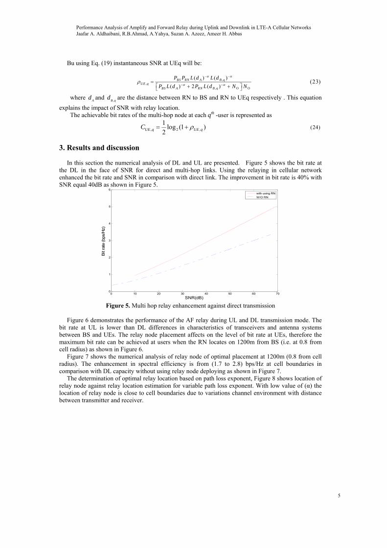
In this section the numerical analysis of DL and UL are presented. Figure 5 shows the bit rate at
the DL in the face of SNR for direct and multi-hop links. Using the relaying in cellular network enhanced the bit rate and SNR in comparison with direct link. The improvement in bit rate is 40% with SNR equal 40dB as shown in Figure 5.
0 10 20 30 40 50 60 700
1
2
3
4
5
6
SNR(dB)
Bit
rate
(bp
s/H
z)
with using RN
W/O RN
Figure 5. Multi hop relay enhancement against direct transmission
Figure 6 demonstrates the performance of the AF relay during UL and DL transmission mode. The
bit rate at UL is lower than DL differences in characteristics of transceivers and antenna systems between BS and UEs. The relay node placement affects on the level of bit rate at UEs, therefore the maximum bit rate can be achieved at users when the RN locates on 1200m from BS (i.e. at 0.8 from cell radius) as shown in Figure 6.
Figure 7 shows the numerical analysis of relay node of optimal placement at 1200m (0.8 from cell radius). The enhancement in spectral efficiency is from (1.7 to 2.8) bps/Hz at cell boundaries in comparison with DL capacity without using relay node deploying as shown in Figure 7.
The determination of optimal relay location based on path loss exponent, Figure 8 shows location of relay node against relay location estimation for variable path loss exponent. With low value of (α) the location of relay node is close to cell boundaries due to variations channel environment with distance between transmitter and receiver.
Performance Analysis of Amplify and Forward Relay during Uplink and Downlink in LTE-A Cellular Networks Jaafar A. Aldhaibani, R.B.Ahmad, A.Yahya, Suzan A. Azeez, Ameer H. Abbas
5

0 500 1000 15003.8
4
4.2
4.4
4.6
4.8
5
5.2
5.4
5.6
5.8
Cell radius R (m)
Bit
rat
e (b
ps/H
z)
AF relay at DL
AF relay at UL
Figure 6. Optimal placement of AF relay to achieve maximum rate at UEq
0 500 1000 15001
2
3
4
5
6
7
Cell Radius (m)
Sp
ect
ral e
ffici
en
cy (
B/S
/Hz)
With RNW/O RN
Figure 7. Spectral efficiency enhancement by using AF relay node at optimal placement
0 0.1 0.2 0.3 0.4 0.5 0.6 0.7 0.8 0.9 13.5
4
4.5
5
5.5
6
drn
/R
Bit
rate
(bp
s/H
z)
AF a=5AF a=4AF a=2
Figure 8. Bit rate performance against AF relay placement
Performance Analysis of Amplify and Forward Relay during Uplink and Downlink in LTE-A Cellular Networks Jaafar A. Aldhaibani, R.B.Ahmad, A.Yahya, Suzan A. Azeez, Ameer H. Abbas
6
Path loss normally includes propagation losses caused by the natural expansion of the radio wave front in free space. In this paper we considered the path loss as function to the distance between sender and receiver therefore the path loss increases with increasing the gap between them as shown in Figure 9.
0 500 1000 150060
70
80
90
100
110
120
130
140
Cell Radius (m)
Pat
hlos
s [d
B]
Figure 9. Path loss varies with cell radius
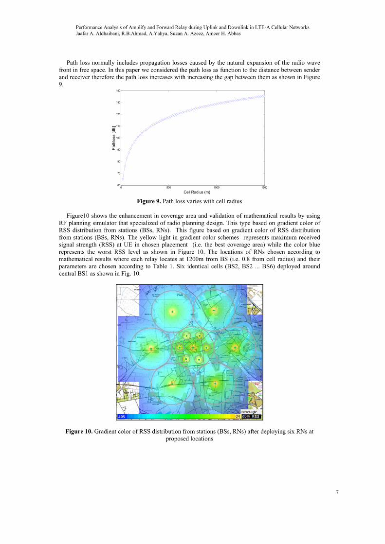
Figure10 shows the enhancement in coverage area and validation of mathematical results by using
RF planning simulator that specialized of radio planning design. This type based on gradient color of RSS distribution from stations (BSs, RNs). This figure based on gradient color of RSS distribution from stations (BSs, RNs). The yellow light in gradient color schemes represents maximum received signal strength (RSS) at UE in chosen placement (i.e. the best coverage area) while the color blue represents the worst RSS level as shown in Figure 10. The locations of RNs chosen according to mathematical results where each relay locates at 1200m from BS (i.e. 0.8 from cell radius) and their parameters are chosen according to Table 1. Six identical cells (BS2, BS2 ... BS6) deployed around central BS1 as shown in Fig. 10.
Figure 10. Gradient color of RSS distribution from stations (BSs, RNs) after deploying six RNs at proposed locations
Performance Analysis of Amplify and Forward Relay during Uplink and Downlink in LTE-A Cellular Networks Jaafar A. Aldhaibani, R.B.Ahmad, A.Yahya, Suzan A. Azeez, Ameer H. Abbas
7
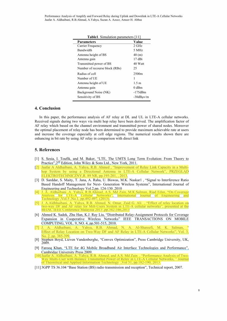
Table1. Simulation parameters [11] Parameters ValueCarrier Frequency 2 GHz Bandwidth 5 MHz
Antenna height of BS 40 (m) Antenna gain 17 dBi
Transmitted power of BS 40 Watt Number of recourse block (RBs) 25
Radius of cell 2500m Number of UE 1
Antenna height of UE 1.5 m Antenna gain 0 dBm
Background Noise (NK) -175dBm
Sensitivity of BS -30dBμv/m
4. Conclusion
In this paper, the performance analysis of AF relay at DL and UL in LTE-A cellular networks.
Received signals during two ways via multi hop relay have been derived. The amplification factor of AF relay which based on the channel environment and transmitted power of shared nodes. Moreover the optimal placement of relay node has been determined to provide maximum achievable rate at users and increase the coverage especially at cell edge regions. The numerical results shown there are enhancing in bit rate by using AF relay in comparison with direct link
5. References
[1] S. Sesia, I. Toufik, and M. Baker, “LTE, The UMTS Long Term Evolution: From Theory to Practice”,2nd Edition, John Wiley & Sons Ltd., New York, 2011.
[2] Jaafar A Aldhaibani, A. Yahya, R.B. Ahmed , “Improvement of Relay Link Capacity in a Multi-hop System by using a Directional Antenna in LTE-A Cellular Network”, PRZEGLĄD ELEKTROTECHNICZNY,R. 89 NR, pp.195-201, , 2013.
[3] D. Sarddar, S. Maity, T. Jana, A. Raha, U. Biswas, M.K. Naskar1 , “Signal to Interference Ratio Based Handoff Management for Next- Generation Wireless Systems”, International Journal of Engineering and Technology Vol.2,pp. 124-130 ,2010
[4] J. A. Aldhaibani ,A. Yahya, R.B.Ahmad, A.S. Md Zain, M.K.Salman, Riad Edan, “On Coverage Analysis for LTE-A Cellular Networks”, International Journal of Engineering and Technology ,Vol.5 ,No.1, pp.492-497, (2013).
[5] J. A.Aldhhaibani, A. Yahya, R.B. Ahmed, N. Omar, Zaid G. Ali , “Effect of relay location on two-way DF and AF relay for Milt-Users System in LTE-A cellular networks”, presented at the BEIAC IEEE Conference Malaysia 2013 ,pp.342-346,2013
[6] Ahmed K. Sadek, Zhu Han, K.J. Ray Liu, “Distributed Relay-Assignment Protocols for Coverage Expansion in Cooperative Wireless Networks” IEEE TRANSACTIONS ON MOBILE COMPUTING, VOL. 9, NO. 4, pp.501-515, 2010.
[7] J. A. Aldhaibani, A. Yahya, R.B. Ahmad, N. A. Al-Shareefi, M. K. Salman, “ Effect of Relay Location on Two-Way DF and AF Relay in LTE-A Cellular Networks”, Vol. 3, No. 2, pp. 385-399.
[8] Stephen Boyd, Lieven Vandenberghe, “Convex Optimization”, Press Cambridge University, UK, 2009.
[9] Farooq Khan, “LTE for 4G Mobile Broadband Air Interface Technologies and Performance”, Cambridge University Press 2009.
[10] Jaafar A. Aldhaibani, A. Yahya, R.B. Ahmed, and A.S. Md Zain , “Performance Analysis of Two-Way Multi-User with Balance Transmitted Power of Relay in LTE-A Cellular Networks, ” Journal of Theoretical and Applied Information Technology ,Vol 51, pp.182-190, 2013.
[11] 3GPP TS 36.104 “Base Station (BS) radio transmission and reception”, Technical report, 2007.
Performance Analysis of Amplify and Forward Relay during Uplink and Downlink in LTE-A Cellular Networks Jaafar A. Aldhaibani, R.B.Ahmad, A.Yahya, Suzan A. Azeez, Ameer H. Abbas
8
Jaafar
Highlight
Jaafar
Highlight
Jaafar
Highlight
Jaafar
Highlight
Jaafar
Highlight
Related Documents