1 Performance Analysis and Optimization of Dowels in Jointed Concrete Floors Ghauch Z. 1 , Karam G. 2 1 Undergraduate student, Department of Civil Engineering, Lebanese American University, Byblos, Lebanon, e-mail: [email protected] 2 Associate Professor, Department of Civil Engineering, Lebanese American University, Byblos, Lebanon, e-mail: [email protected] Abstract This study examines the performance of traditional round dowels in concrete floors and attempts to optimize the shape of dowel bars through Finite Element (FE) analysis. A new type of Double-Tapered Round (DTR) dowels is proposed, and the performance of DTR dowels is compared to that of traditional cylindrical dowels. Linear Elastic (LE) analysis is performed in Abaqus (v-6.11) in order to identify the optimized geometry of DTR dowels that would achieve (1) highest load transfer across adjacent slabs through shear action, and (2) lowest bearing stresses on the concrete. LE analyses are complemented by nonlinear FE analysis. The Riks method available in Abaqus/Standard, coupled with the Concrete Damaged Plasticity (CDP) model is used to simulate the degradation of concrete surrounding both DTR and traditional cylindrical dowels. Results obtained show that the use of DTR dowels can reduce bearing stresses at the face of the joint by as much as 2.2 times as compared to traditional cylindrical dowels. While adequate load-transfer is a crucial part for the proper performance of pavement structures, the load-transfer capacity of DTR dowels was found to be more effective over cylindrical dowels by as far as 116%. In the inelastic range, even after significant concrete degradation and steel yielding, DTR dowels maintained a higher load-transfer capacity than traditional cylindrical dowels, and also presented lower amounts of differential deflections across concrete floors. Finally, damage in the concrete matrix below the dowel was relatively more confined for the case of DTR dowels, as compared to traditional cylindrical dowels.

Welcome message from author
This document is posted to help you gain knowledge. Please leave a comment to let me know what you think about it! Share it to your friends and learn new things together.
Transcript

1
Performance Analysis and Optimization of Dowels in Jointed
Concrete Floors
Ghauch Z.1, Karam G.2
1Undergraduate student, Department of Civil Engineering, Lebanese American University,
Byblos, Lebanon, e-mail: [email protected]
2Associate Professor, Department of Civil Engineering, Lebanese American University, Byblos,
Lebanon, e-mail: [email protected]
Abstract
This study examines the performance of traditional round dowels in concrete
floors and attempts to optimize the shape of dowel bars through Finite Element
(FE) analysis. A new type of Double-Tapered Round (DTR) dowels is proposed,
and the performance of DTR dowels is compared to that of traditional cylindrical
dowels. Linear Elastic (LE) analysis is performed in Abaqus (v-6.11) in order to
identify the optimized geometry of DTR dowels that would achieve (1) highest
load transfer across adjacent slabs through shear action, and (2) lowest bearing
stresses on the concrete. LE analyses are complemented by nonlinear FE analysis.
The Riks method available in Abaqus/Standard, coupled with the Concrete
Damaged Plasticity (CDP) model is used to simulate the degradation of concrete
surrounding both DTR and traditional cylindrical dowels. Results obtained show
that the use of DTR dowels can reduce bearing stresses at the face of the joint by
as much as 2.2 times as compared to traditional cylindrical dowels. While
adequate load-transfer is a crucial part for the proper performance of pavement
structures, the load-transfer capacity of DTR dowels was found to be more
effective over cylindrical dowels by as far as 116%. In the inelastic range, even
after significant concrete degradation and steel yielding, DTR dowels maintained
a higher load-transfer capacity than traditional cylindrical dowels, and also
presented lower amounts of differential deflections across concrete floors. Finally,
damage in the concrete matrix below the dowel was relatively more confined for
the case of DTR dowels, as compared to traditional cylindrical dowels.

2
Keywords: Concrete pavements; dowels; finite element method.
Introduction
Background
Despite the overall satisfactory performance of cylindrical steel dowels in concrete pavements,
several flaws in the performance of cylindrical dowels have been identified. Among other
things, traditional steel dowels are subject to: (1) corrosion of steel material, (2) restraint stresses
and slab cracking associated with dowel misalignment, and (3) reduced load transfer efficiency
due to dowel looseness and formation of voids in the concrete matrix surrounding the dowel.
Dowel looseness is mainly associated with high bearing stresses exerted on the concrete due to
the relatively low bearing area of cylindrical dowels (ACPA 2010).
We recall that the general equation for the deflection of a dowel structure extending infinitely
into an elastic mass can be written as follows (Friberg 1938):
���� = ���2�� �� ������� + � ��2 ������ − �������[1] Where β is the relative stiffness of the dowel structure and is defined as follows:
� = � ø4 ��" [2] In equation [2], Es and I are the modulus of elasticity and moment of inertia of the dowel bar,
respectively, ø is the diameter of dowel bar, and K is the modulus of dowel-support, representing
the pressure intensity (MPa) required to induce a 1mm settlement, and P is the downward shear
acting on the dowel, and transferred from one PCC slab to the next. The bearing stress can be
expressed as a function of the dowel deflection at the face of the joint (yo) and the modulus of
dowel support K as follows:
#$ = �$ = �2�� �� �1 + ��2 �[3]

3
Figure 1 – Deflection shape of embedded dowel in semi-infinite elastic mass
Although the modulus of dowel support is of crucial importance in Friberg (1938) design
equations, no appropriate theoretical method exists for the determination of this parameter. The
only way for computing the modulus of dowel support is through experimental testing.
Moreover, there is considerable uncertainty in design as to the selection of a proper value for the
modulus of dowel support, since values of K typically range from 81.5 to 409 N/mm-3
.
Mannava et al. (1999) conducted a series of experimental load-deflection tests on cylindrical
dowels with varying diameter, concrete strength, and joint width. The laboratory setup consisted
of a single dowel bar connecting a loaded block to a reacting block; a static load applied through
a hydraulic jack, and the resulting deflection profile along the embedded dowel was measured
using a series of Linear Variable Displacement Transducers (LVDTs). The study observed that in
order to match experimental deflections measured along the dowel with Friberg’s analytical
solution, several K-values were required. This raises the question as to how far the original
assumption of uniform modulus of dowel support along the dowel is accurate.
Using the dowel deflection equation (equation [1]) presented by Timoshenko (1925) and revised
by Friberg (1940), the shear in the dowel structure at any point x can be defined as follows:
&��� = −���[�−��� − �� ��� �� + � ��� ��][4]
� 2'
ø
y
x
Pz 2' y[x]
Semi-infinite
elastic mass
Dowel structure

4
Traditional methods for dowel design are based on empirical methods. The dowel diameter is
directly selected based on the pavement thickness. An early empirical attempt for dowel design
was to select the diameter of cylindrical dowels equal to one-eighth of the concrete slab
thickness (PCA 1975). Further suggestions were made in terms of using a minimum dowel
diameter of 1.25 in. in order to control the amount of faulting associated with bearing stress in
the concrete. In 1991, PCA suggested using 1.25 in. dowel diameters for concrete slabs less than
10 in. thickness, and 1.5 in. dowels for slabs with higher thicknesses.
Another method for sizing dowels is based on the bearing stress in the concrete. The diameter of
the dowel is selected so that the bearing stress exerted by the dowel on the concrete, as expressed
by equation [3], remains below the allowable bearing stress of concrete given as follows (ACI
1956):
#$,+,, = -4 − ø3 ./0′[5] Review of Commonly Used Dowel Shapes in Concrete Floors
Traditional round dowels restraint the lateral movement of the slab parallel to the joint,
movements that are associated with temperature variations. Dowel misalignment further restraint
lateral displacements, thus increasing stresses and the potential for cracking in concrete floors.
Schrader (1991) suggested a solution to the above problem by adopting square dowels equipped
with compressible material attached along the vertical sides. In fact, the use of compressible
material allows for unrestricted lateral displacement between adjacent slabs, thus eliminating the
problem of restraint stresses and dowel misalignment. A high-density plastic clip, which
significantly increased the cost of using square dowels, was later added in order to protect and
hold the compressible material during construction.
Porter et al. (2001) investigated the performance of elliptical dowel bars in concrete slabs. The
main advantage of elliptical dowels over traditional round dowels is in the increased bearing area
and the resulting reduction in bearing stress on the concrete. However, the advantages of using
elliptical dowel shapes are counterbalanced by difficulties in placement as well as availability
concerns.
5
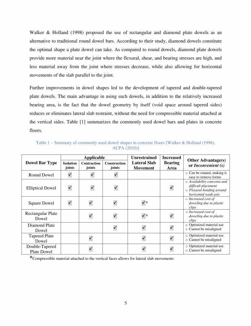
Walker & Holland (1998) proposed the use of rectangular and diamond plate dowels as an
alternative to traditional round dowel bars. According to their study, diamond dowels constitute
the optimal shape a plate dowel can take. As compared to round dowels, diamond plate dowels
provide more material near the joint where the flexural, shear, and bearing stresses are high, and
less material away from the joint where stresses decrease, while also allowing for horizontal
movements of the slab parallel to the joint.
Further improvements in dowel shapes led to the development of tapered and double-tapered
plate dowels. The main advantage in using such dowels, in addition to the relatively increased
bearing area, is the fact that the dowel geometry by itself (void space around tapered sides)
reduces or eliminates lateral slab restraint, without the need for compressible material attached at
the vertical sides. Table [1] summarizes the commonly used dowel bars and plates in concrete
floors.
Table 1 – Summary of commonly used dowel shapes in concrete floors [Walker & Holland (1998),
ACPA (2010)]
Dowel Bar Type Applicable Unrestrained
Lateral Slab Movement
Increased Bearing
Area
Other Advantage(s) or Inconvenient (s)
Isolation joints
Contraction joints
Construction joints
Round Dowel � � � o Can be rotated, making it
easy to remove forms
Elliptical Dowel � � � �
o Availability concerns and
difficult placement
o Flexural bending around
horizontal weak axis
Square Dowel � � � �* o Increased cost of
doweling due to plastic
clips
Rectangular Plate
Dowel � � �* �
o Increased cost of
doweling due to plastic
clips
Diamond Plate
Dowel � � �
o Optimized material use
o Cannot be misaligned
Tapered Plate
Dowel � � �
o Optimized material use
o Cannot be misaligned
Double-Tapered
Plate Dowel � � �
o Optimized material use
o Cannot be misaligned
*Compressible material attached to the vertical faces allows for lateral slab movements
6
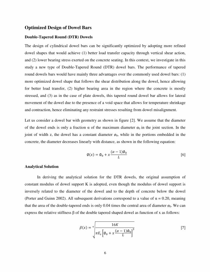
Optimized Design of Dowel Bars
Double-Tapered Round (DTR) Dowels
The design of cylindrical dowel bars can be significantly optimized by adopting more refined
dowel shapes that would achieve (1) better load transfer capacity through vertical shear action,
and (2) lower bearing stress exerted on the concrete seating. In this context, we investigate in this
study a new type of Double-Tapered Round (DTR) dowel bars. The performance of tapered
round dowels bars would have mainly three advantages over the commonly used dowel bars: (1)
more optimized dowel shape that follows the shear distribution along the dowel, hence allowing
for better load transfer, (2) higher bearing area in the region where the concrete is mostly
stressed, and (3) as in the case of plate dowels, this tapered round dowel bar allows for lateral
movement of the dowel due to the presence of a void space that allows for temperature shrinkage
and contraction, hence eliminating any restraint stresses resulting from dowel misalignment.
Let us consider a dowel bar with geometry as shown in figure [2]. We assume that the diameter
of the dowel ends is only a fraction α of the maximum diameter ø0 in the joint section. In the
joint of width z, the dowel has a constant diameter ø0, while in the portions embedded in the
concrete, the diameter decreases linearly with distance, as shown in the following equation:
∅��� = ∅3 + � �4 − 1�∅35 [6] Analytical Solution
In deriving the analytical solution for the DTR dowels, the original assumption of
constant modulus of dowel support K is adopted, even though the modulus of dowel support is
inversely related to the diameter of the dowel and to the depth of concrete below the dowel
(Porter and Guinn 2002). All subsequent derivations correspond to a value of α = 0.20, meaning
that the area of the double-tapered ends is only 0.04 times the central area of diameter ø0. We can
express the relative stiffness β of the double tapered shaped dowel as function of x as follows:
���� = 7 16 8 � �∅3 + � �4 − 1�∅35 ��" [7]

7
Substituting the expression for β(x) into the general equations for deflection y(x) (equation [1])
and vertical shear V(x) (equation [4]) respectively, we obtain the following equations:
�:��� = �����2����� ����� ;� ���[�����] + ������2 ����[�����] − ���[�����]�<[8] &:��� = −�����[�−������ − �� ���[�����] + � ���[�����]][9]
At the face of the joint (x = 0), the deflection of the double-tapered dowel is:
�:�0� = �2�3� ��3 �1 + �3�2 �[10] Where
�3 = ��0� = � 16 8 �∅3�" �3 = ��0� = 864∅3@
Linear FE Analysis using Abaqus (2011)
A FE analysis of the performance of DTR dowels as compared to traditional cylindrical dowels
was performed using the FE code ABAQUS (2011). A total of five computational runs were
performed, each with a varying parameter α that ranges from 0.0 to 1.0 in 0.2 increments. Again,
all the simulated cases (as shown in the upper left table of Figure [3]) involve DTR dowels with
the same weight of steel as a 35 mm traditional cylindrical dowel.
In the FE model, 16116 quadratic solid elements (C3D20R) were used to model the dowel bar,
with an average element size of 2.5 mm. Due to symmetry, only half of the dowel was simulated.
A typical embedment length of 250 mm was adopted. A Winkler foundation support was applied
on the embedded surface of the dowel bar. The stiffness of the Winkler foundation is nothing but
the modulus of dowel support K; a value of 150 N.mm-3
was adopted. Symmetry boundary
conditions were applied along the vertical mid-plane of the dowel.

8
Figure 2 – (a) Geometry configuration of DTR dowel, and (b) 3D FE mesh of DTR dowel (full model)
The maximum shear force P at the midpoint of the dowel was applied as a distributed pressure
over the circular cross section of the DTR dowel of diameter ø0. The value of P, the maximum
shear force carried by the dowels is usually calculated by multiplying the magnitude of the
applied wheel load by approximately 0.45 (Yoder & Witczak 1975) that accounts for the load
transferred across the joint, then dividing the obtained number by the amount of effective dowels
participating in load transfer. A value of P = 3000 N was chosen in order to later compare
numerical results with analytical solutions. The moment Mo applied at the face of the joint was
calculated from the maximum shear P and the joint width z as Mo=Pz/2.
Performance of Cylindrical and DTR Dowels
In order to perform comparative analysis between traditional cylindrical dowels (of diameter ø
and length L) and new dowel bar shapes, the same weight of steel material should be used for
∅�x� � ∅3 � x �α� 1�∅3L
z L
x
ø0
ø(x) α ø0

9
both dowel shapes. If the same weight of material can be used in DTR dowels to achieve better
performance in terms of lower bearing stresses and higher amount of load transfer, then the
dowel spacing can be increased. By equating the volume of the traditional dowel bar with the
volume of the new tapered dowel, we obtain an expression relating the diameter ø of the
traditional cylindrical dowel to the parameters ø0 and α of the DTR dowel, as shown in the
following equation:
∅∅3 = �� +235�1 − 4�1 − 4 �25 + � [11]
In the above equation, as α tends to unity, the above equation reduces to ø = ø0, which
corresponds to the case of traditional cylindrical dowels.
In order to compare the performance of traditional cylindrical dowels with DTR dowels, the
following criteria were examined: (1) bearing stress on concrete and (2) vertical shear force
along the dowel.
Bearing Stress on Concrete (load-controlled)
The bearing stress σt(x) along the DTR dowel can be expressed by replacing the expression for
β(x) shown in equation [7] into equation [1] for the deflection, and then multiplying y(x) by the
modulus of dowel support K:
#C��� = �:��� = �����2����� ����� ;��������� + ������2 ��������� − ���������<[12]

10
Figure 3 – Comparison of bearing stress along traditional cylindrical and DTR dowels of varying α, with
K = 150 N.mm-3
, z = 10 mm, P = 3000 N, ES = 200000 N.mm-2
, L = 250 mm (the same weight of material
is used in all cases)
Figure [3] plots the analytical and numerical solutions for bearing stress along DTR dowels of
equal weight but with varying geometry. In the analytical solution, equation [12] is plotted for
α = 0.2
α = 0.4
α = 0.6
α = 0.8
α = 1.0
-0.4
0
0.4
0.8
1.2
1.6
2
2.4
2.8
3.2
3.6
0 25 50 75 100 125 150 175 200 225 250
Bea
rin
g s
tres
s o
n c
on
cret
e (M
Pa
)
Distance along dowel (x, mm)
Numerical Solution, α = 0.2
Numerical Solution, α = 1.0
α Ø0 (mm) α Ø0 (mm)
0.2 54 11
0.4 48 19
0.6 43 26 0.8 39 31
1.0 35 35

11
several values of α (0.2, 0.4, 0.6, 0.8, and 1.0), as shown in the solid lines of Figure [3]. In the
numerical solution, the extreme cases of α = 1.0 (cylindrical dowel) and α = 0.20 are plotted.
For the case of traditional cylindrical dowels (α = 1.0), Friberg’s analytical solution, as compared
to the numerical solution, overestimates the bearing stresses along the concrete, particularly near
the joint faces, where the analytical solution is 16.1% higher than FE results. This relative
discrepancy between the analytical and numerical solutions leads back to the conclusions of
Mannava et al. (1999) that a uniform modulus of dowel support is insufficient for capturing the
deformation profile (or bearing stress) along the dowel. The same discrepancy is observed
between the analytical and numerical solutions for the case of α = 0.20. However, near the joint
faces, the difference reduces to only 0.5%.
While keeping the same volume of material, as the slope of the tapered sides increases, the
bearing stresses along the concrete drop, as shown in the solid lines of Figure [3]. This is
particularly true near the joint face, where as the parameter α goes from 1.0 to 0.2, the bearing
stress drop by approximately 2.2 times.
A summary of the cases investigated ranging from traditional cylindrical dowels (α = 1.0) to
perfectly double-cone shaped dowel (α = 0.0) is shown in the table of figure [3]. Given the value
of α that ranges from 0 to 1, the ratio ø/ø0 was calculated using equation [11] for ø = 35 mm in
order to compare the performance of dowels for the same weight of material.
In order to compare the performance of the proposed DTR dowel with traditional cylindrical
dowels, (1) the bearing stress for the DTR dowel σt0 at the face of the joint (x = 0.0) is
normalized to the corresponding bearing stress σ0 for a typical ø = 35 mm cylindrical dowel. We
recall that ø0 is the maximum central diameter of the DTR dowel. The bearing stress ratio σt0/σ0
can be expressed using the expression for the deflection of the embedded portion of the dowel at
the joint face for cylindrical (y0) and DTR dowels (yt0):
#:,3#3 � �:,3
�3 � ����2 � �3���3��3�2 � ���[13]
Since we are dealing with relatively small joint widths, we can further assume that the ratios
(2+β0z) ≈ (2+βz) ≈ 2, hence reducing the above equation into:

12
#:,3#3 � Dø3
øE�F.HI
[14]

13
0.3
0.4
0.5
0.6
0.7
0.8
0.9
1.0
1.00 1.07 1.14 1.21 1.28 1.35 1.42 1.49 1.56 1.63 1.70
σt,
0 / σ
0
øo/ø
Analytical solution
Numerical solution
#J,0#0 � -ø0ø .
�1.75

14
Figure 4 – Normalized bearing stress as a function of dowel parameter α (or ø/ø0)
Figure [4] plots the normalized bearing stress (σt0/σ0) as a function of the diameter ratio ø0/ø. We
recall that σt0 and σ0 represent the bearing stresses at the face of the joint for the DTR and
cylindrical dowels, respectively. While the analytical solution matches the numerical solution at
ø0/ø = 1.0 (or α = 1, cylindrical dowel), as the ratio ø0/ø increases (the slopes of the dowel
become more and more tapered, for the same weight of material), the analytical solution diverges
from the numerical solution. For the extreme case of α = 0.2 (ø0/ø = 1.5), the analytical solution
differs from the numerical solution by approximately 26%, and the difference decreases as α
increases to 1.0. One of the main reasons of divergence between the analytical and numerical
0.3
0.4
0.5
0.6
0.7
0.8
0.9
1.0
1.00 1.07 1.14 1.21 1.28 1.35 1.42 1.49 1.56 1.63 1.70
σt,
0 / σ
0
øo/ø

15
solutions is that the modulus of dowel support, as mentioned earlier, is dependent on the dowel
diameter. Thus, the assumption of uniform modulus of dowel support along the DTR dowel
(with varying diameter) should be verified. Since the modulus of dowel support is inversely
related to the diameter of the dowel, in the vicinity of the joint face, where the diameter of the
DTR dowel is highest, the modulus of dowel support K should be appropriately reduced.
In addition, equation [14], which is an approximation of the analytical solution, is plotted on
Figure [4]. Equation [14] slightly differs from the analytical solution, mainly because of the
assumption of negligible joint width z.
The advantages of using DTR as compared to cylindrical dowels in terms of reduced bearing
stresses are visualized in Figure [4]. As the slopes of the tapered sides of the DTR dowel increase
(the ratio ø0/ø increase), the bearing stress ratio σt0/σ0 at the face of the joint drops. According to
the numerical solution for the case of α = 0.20, (or ø0/ø = 1.5), the bearing stress at the joint face
for the DTR dowel is only 58% of the corresponding bearing stress for the traditional cylindrical
dowel.
Vertical Shear Force in Dowel (displacement-controlled)
In order to compare the load-transferring capacity of both traditional cylindrical and DTR
dowels, the amount of shear force corresponding to a specific amount of deflection in the dowel
is determined. In other words, a vertical downward displacement is imposed on the dowel at the
joint face and the corresponding shear force is calculated. Using the deflection equation of the
dowel at the face of the joint, the maximum shear force P corresponding to y0 = 0.01 mm is
computed for all other parameters equal (ESteel = 200,000 MPa, K = 150 N.mm-3
, L = 250 mm, ø
= 35 mm, and z = 10 mm), as shown in the following sample calculation. For the cylindrical
dowel (α = 1.0), the maximum shear force P0 necessary to induce a 0.01 mm vertical deflection
at x = 0.0 is:
� � 2�� ��[1 + �� 2⁄ ] �3
Solving for P = 1400 N. For the DTR dowel with α = 0.20, the maximum shear force Pt
necessary to induce a 0.01 mm vertical deflection at x = 0.0 is:

16
�: � 2�3� ��3[1 + �3� 2⁄ ] �:,3
Solving for Pt = 3024 N.
The distribution of shear along the dowel is then plotted using equation [10]. We recall that for
cylindrical dowels (α = 1.0), equation [10] reduces to the traditional equation of shear along the
dowel presented by Friberg (1938), with β(x) given by equation [7]. The shear distribution is
plotted in Figure [5] with values of α ranging from 0.2 to 1.0 in 0.2 increments. The
corresponding central diameters ø0 for each DTR dowel are shown in the table of Figure [5]. At
this point, we recall two things, (1) αø0 represents the end diameter of the DTR dowel, and (2) all
dowels shown with α ranging from 0.2 to 1.0 have the same weight.
The use of DTR dowels, particularly for low values of α, increases the amount of load
transferred through vertical shear, as shown in Figure [5]. As the value of α drops from 1.0
(which represents cylindrical dowel) to 0.2, the corresponding maximum shear force P at the
joint face increases. This implies that the amount of load transferred via the dowel is directly
proportional to the slope of the DTR dowel. The highest load-transfer is achieved for the DTR
dowel with the lowest α. In fact, as α drop from 1.0 to 0.2, the maximum shear force along the
dowel increases by 116%. The fact that the DTR dowel has a better load-transfer capability than
traditional cylindrical dowel can be significantly beneficial in extending the life of doweled rigid
pavements.

17
Figure 5 - Comparison of shear force along cylindrical and DTR dowels corresponding to y0 = 0.01 mm
α = 0.2
α = 0.4
α = 0.6
α = 0.8
α = 1.0
-3500
-3000
-2500
-2000
-1500
-1000
-500
0
500
1000
0 25 50 75 100 125 150 175 200 225 250
Shea
r P
t , N
Distance along dowel x, mm
α Ø0 (mm) α Ø0 (mm)
0.2 54 11
0.4 48 19
0.6 43 26
0.8 39 31
1.0 35 35

18
Non-Linear FE Analysis using Abaqus (2011)
In order to further compare the performance of traditional cylindrical and DTR dowels, a non-
linear FE Analysis was conducted using Abaqus (2011). The model includes a steel dowel
embedded in a concrete mass. The dowel extends from the joint face by a distance of z/2, where
z is the joint width. Due to symmetry, only half of the assembly was modeled, as shown in
Figure [6], and z-symmetry was imposed along the vertical x-y mid-plane. Fixed BC’s were
imposed along the other boundaries, except the vertical joint face. A biased mesh was
implemented, as shown in Figure [6], with the smallest elements in the vicinity of the dowel.
Quadratic solid elements (C3D20R) were used to model both the dowel and the surrounding
concrete. Full bonding between the dowel and the concrete matrix was assumed.
Figure 6 – 3D Finite Element mesh configuration of non-linear model.

19
Table 2 – Elastic-Plastic properties for steel material and parameters for the Concrete Damaged Plasticity
(CDP) model
Steel Properties
Young's modulus (MPa) 200000
Poisson's ratio 0.3
Yield stress (MPa) 345
Concrete Properties Young's modulus (MPa) 31027
Poisson's ratio 0.15
Dilation angle 36.31°
Compressive initial yield stress (MPa) 13
Compressive ultimate stress (MPa) 24.1
Tensile failure stress (MPa) 2.9
An Elastic-Plastic model for the steel material in the dowel bar was adopted, as shown in Table
[2]. The concrete mass was modeled in Abaqus/Standard using the Concrete Damaged Plasticity
(CDP) model (Lubliner et al. 1989, Lee and Fenves 1998). In the CDP model, isotropic damaged
elasticity is coupled with isotropic compressive and tensile plasticity. In tension, softening
response occurs and post-failure behavior is specified in terms of a stress-displacement curve,
while in compression, initial hardening is followed by softening behavior. The parameters of the
concrete damaged plasticity model were obtained from Bhattacharjee et al. (1993) & Ghrib and
Tinawi (1995), as shown in Table [2].
The solution was obtained using the Riks method in Abaqus/Standard, given that significant
nonlinearity is expected in the solution as the concrete degrades and the dowel yields. An
automatic incrementation was adopted, with an initial increment size of 0.001. An ultimate load
of 150 KN was applied as shear traction over the free end of the dowel, for a total time period of
1.0. Since only half of the assembly was modeled, half of the ultimate load was applied at the
dowel free end.

20
Stress-Displacement Response
Figure 7 – Vertical stress versus deflection at the midpoint (point A) of DTR (α = 0.20) and cylindrical
dowels (ø = 35 mm)
Figure [7] visualizes the stress-displacement response at the midpoint of both DTR and
cylindrical dowel. The midpoint of the dowel is represented by point A in the upper left diagram
on Figure [7]. It can be observed that DTR dowels have mainly two advantages over cylindrical
dowels in the inelastic range: (1) higher load-carrying capacity, particularly as the concrete
surrounding the dowel degrades and the steel in the dowel itself yields; (2) lower vertical
-100
-90
-80
-70
-60
-50
-40
-30
-20
-10
0
-0.6-0.5-0.4-0.3-0.2-0.1-1E-15
Ver
tica
l S
tres
s, S
22
(M
Pa
)
Vertical Deflection, U2 (mm)
Double-Tapered (α=0.20)
Cylindrical (ø = 35 mm)
Semi-infinite
elastic mass
Dowel structure
� 2'
A

21
differential deflections across the concrete floors. The above two point are extremely beneficial
in extending the service life of the doweled rigid pavement under repetitive loading.
Damage Propagation Analysis
The stiffness degradation (SDEG) of the concrete matrix around the dowel is plotted in Figure
[8a and 8b] in the longitudinal (x/L) and vertical directions (y/ø or y/ø0) respectively. SDEG
profiles for both the DTR and cylindrical dowels were obtained at two steps corresponding to a
downward vertical displacement at the dowel midpoint (point A) of 0.1 mm and 0.5 mm. We
bear in mind that according to Friberg’s (1938) analytical model, a displacement at the dowel
midpoint of 0.5 mm corresponds to a total differential deflection across slabs of 1 mm.
The stiffness damage scalar is plotted in the longitudinal direction (x / L) in Figure [8a]. It can be
noted that the damage in the concrete was confined to the face of the joint; above x/L = 0.35,
practically no damage occurs.
The level of SDEG in the concrete with the DTR dowel was higher than that of the case of the
traditional cylindrical dowel, for both midpoint deflections of -0.1 and -0.5 mm. This implies that
the use of DTR dowel, as compared to cylindrical dowels, is beneficial in terms of reduced
differential deflection across slabs. In fact, in order to achieve the same level of differential
deflection (=twice the deflection at point A), the DTR dowel allows for more concrete
degradation than the cylindrical dowel. The cylindrical dowel deflects by -0.1 mm when the
SDEG parameter at the face of the joint is equal to 0.48, while for the DTR dowel, the same
deflection is reached when degradation of the concrete at the joint face reaches 0.65. The same
is true for the case of U2 @ A = -0.5 mm, where the DTR dowel allows for higher concrete
degradation as compared to the cylindrical dowel before if deflects by 0.5 mm at its midpoint
(point A).
This leads to the idea that the performance of DTR dowels is better than the cylindrical dowel
not only in the elastic range, but even after the concrete matrix surrounding the dowel has
degraded. In fact, it can be concluded from Figure [8a] that with the degradation of concrete
around dowels under repetitive loading, the differential deflection across slabs with DTR dowels
is significantly lower than the corresponding value with cylindrical dowels.

22
Figure 8 - Stiffness degradation in concrete matrix for DTR and cylindrical dowels (a) along x/L (0 ≤ x/L
≤ 0.35), and (b) along y/ø or y/ø0
0.0
0.2
0.4
0.6
0.8
1.0
0 0.05 0.1 0.15 0.2 0.25 0.3 0.35
Sti
ffn
ess
Deg
rad
ati
on
(S
DE
G)
x / L
U2=-0.1mm
U2=-0.5mmU2=-0.1mm
U2=-0.5mm
― Double-Tapered Round (α = 0.20)
--- Cylindrical Dowel
0.0
0.2
0.4
0.6
0.8
1.0
0 0.1 0.2 0.3 0.4 0.5 0.6
Sti
ffn
ess
Deg
radati
on (
SD
EG
)
y / ø or y / ø0
U2=-0.1mm
U2=-0.5mm
U2=-0.1mm
U2=-0.5mm
― Double-Tapered Round (α = 0.20)
--- Cylindrical Dowel

23
Figure [8b] plots the stiffness degradation scalar in the concrete at the face of the joint in the
vertical direction; y is a downward vertical axis, whose plane is the face of the joint, and with
origin the bottom of the dowel (@ x = 0.0). The value of y is normalized to the diameter ø0 in the
case of DTR dowels, and ø in the case of cylindrical dowels. Results are shown at two midpoint
dowel deflections of -0.1 and -0.5 mm.
It can be observed first from Figure [8b] that for the case of the traditional cylindrical dowel,
stiffness degradation was confined within a distance of y/ø = 0.53, i.e. damage propagated
downward by 0.53 ø, whereas for the case of the DTR dowel, stiffness degradation occurred
within a distance of y/ø0 = 0.15, or damage propagated downward by 0.15ø0. This implies that
one of the advantages of using DTR dowels over cylindrical dowels is in confining the damage
in the concrete in the vicinity of the dowel. As shown in Figure [8b], damage propagation below
the DTR dowel is only approximately 28% of the corresponding damage below the cylindrical
dowel.
Conclusions and Recommendations
This study numerically investigated the performance of traditional round dowels in concrete
floors. The design of traditional cylindrical dowels was optimized through Finite Element (FE)
analysis. A new type of Double-Tapered Round (DTR) dowels was proposed, and the latter’s
superior performance over traditional cylindrical dowels was verified through LE and nonlinear
FE analysis in Abaqus (v-6.11). The study found that for the same weight of steel material in the
dowel, the bearing stress at the face of the joint dropped by approximately 2.2 times as α goes
from 1.0 to 0.2 and the slope of the tapered sides increased.
The analytical and numerical solution for the DTR dowel slightly diverged as α dropped from
1.0 to 0.2 due to varying modulus of dowel support K. While K is inversely related to the
diameter of the dowel, near the joint face, the diameter of the DTR dowel is highest, and K
should be adequately reduced.
As for the amount of vertical load-transfer through shear, DTR dowels were found more
effective in transferring the load across concrete slabs. As the dowel slopes become more and

24
more tapered (α goes from 1.0 to 0.2), the load-transfer capability of the dowel increased by as
far as 116%. This underlines the fact that DTR dowels have a better load-transfer capacity than
traditional cylindrical dowel, something that can extend the life of the doweled rigid pavement
under cyclic loading.
In the inelastic range, the performance of DTR dowels outweighed that of traditional cylindrical
dowels. With the degradation of the concrete matrix and steel yielding, the DTR dowel
maintained a higher load-transfer capacity than the traditional cylindrical dowel, and presented
lower amounts of differential deflections across concrete floors. In fact, even after extensive
degradation of concrete around the dowels, the differential deflection across slabs with DTR
dowels was significantly lower than the corresponding value with cylindrical dowels. In order to
reach the same level of differential deflection, the DTR dowel allows for more concrete
degradation than the cylindrical dowel.
For both DTR and cylindrical dowels, damage was practically confined at the face of the joint;
beyond a distance of x / L of 0.35, no degradation of concrete matrix occurred. In the vertical
direction at the face of the joint, for cylindrical traditional dowels, damage occurred within a
distance of 0.53 ø below the dowel, while for the DTR dowel, damage propagated a distance of
only 0.15 ø0 below the dowel. This leads to the idea that DTR dowel are more effective in
confining the damage to the vicinity of the dowel.
Several recommendations on the design of DTR dowels can be presented; among other things,
for ease of manufacturing, the diameter of the DTR dowel can continue to linearly increase along
the joint. The results presented earlier would not be affected whether the dowel diameter is
constant (ø0) or linearly tapered along the joint, mainly because the joint has negligible width
compared to the DTR dowel dimensions.
In order for the DTR dowel to function properly and present sufficient load transfer, the bottom
and the top of the dowel must be in complete contact with the surrounding concrete. Void space
should be left on the lateral sides of the DTR dowel through the sleeve assembly, in order to
allow for unrestrained lateral displacement. Similarly, void space should be left at the end of the
dowel to allow for thermal expansion/contraction. In order to achieve optimum design of DTR

25
dowels, the value of α should be chosen as small as possible, yet not too small in order to allow
for a void space near the embedded end of the dowel.
One of the potential difficulties that would be encountered in using DTR dowels would be in the
design of dowel sleeves in order to (1) provide a void space in the horizontal direction to allow
for expansion of the dowel under increased temperatures, and (2) account for dowel
misalignment. In the vertical direction, the sleeve should be in contact with the tapered-dowel
faces in order to allow for a fully efficient load transfer between adjacent concrete slabs.
List of Abbreviations
y = vertical deflection along the cylindrical dowel (L)
yt = vertical deflection along the double-tapered dowel (L)
σ = bearing stress on concrete for cylindrical dowel (FL-2
)
σt = bearing stress on concrete for double-tapered round dowel (FL-2
)
ES = modulus of elasticity of steel (FL-2
)
P = maximum shear force carried by the dowel along the joint (F)
I = moment of inertia of dowel (L4)
z = joint width (L)
β = relative stiffness of dowel (L-1
)
K = modulus of dowel support (FL-3
)
ø = diameter of cylindrical round dowel (L)
V = vertical shear force along the cylindrical dowel (F)
Vt = vertical shear force along the double-tapered dowel (F)
ø0 = central diameter of double-tapered round dowel (L)
α = ratio of double-tapered dowel end diameter to central diameter ø0

26
L = embedment length of dowel (L)
fc' = compressive strength of concrete (FL
-2)
D.T.R. dowel = double-tapered round dowel
References
Abaqus. (2011). Abaqus/Standard User’s Manual, Version 6.11. Dassault Systèmes, 2011.
ACI Committee 325, “Structural design considerations for pavement joints,” Journal of the
American Concrete Institute, Vol. 28, No. 1, July 1956, pp. 1-28.
Bhattacharjee, S.S., and Leger, P. (1993). “Seismic cracking and energy dissipation in concrete
gravity dams.” Earthquake Engineering and Structural Dynamics, Vol. 22, No. 11, pp.
991-1007.
Friberg, B.F. (1938). “Design of dowels in transverse joints of concrete pavements.” Trans.,
ASCE, 105, 1076-1095.
Ghrib, F., and Tinawi, R., (1995). “An application of damage mechanics for seismic analysis of
concrete gravity dams.” Earthquake Engineering and Structural Dynamics, Vol. 24, No.
2, pp. 157-173.
Lee, J., Fenves, G.L. (1998). “Plastic-damage model for cyclic loading of concrete structures.” J.
Eng. Mech., 124 (8), pp. 892-900.
Lubliner, J., Oliver, J., Oller, S., Oňate, E. (1989). “A plastic-damage model for concrete.” Int. J.
Solids Struct., 25, pp. 299-329.
Mannava, S.S., Bush, T.D., and Kukreti, A.R. (1999), “Load-deflection behavior of smooth
dowels,” Structural Journal, Vol. 96 (6), pp. 891 – 898
“Plate Dowels an innovation driven by industrial concrete paving,” American Concrete
Pavement Association, April 2010
27
Porter, M.L., Guinn, R.J., and Lundy, A.L., “Dowel Bar Optimization: Phase I and II”, Center
for Transportation Research and Education, October 2001.
Porter, M.L., & Guinn, R.J., “Assessment of dowel bar research”, Center for Transportation
Research and Education, August 2002.
Portland Cement Association, (1991), Concrete Paving – 100 Years of Progress Through
Innovation. Concrete in Highway Transportation, No. 10, Portland Cement Association,
Skokie, IL.
Portland Cement Association, (1975), Basic Concrete Construction Practices, John Wiley &
Sons, Inc., New York.
Schrader, E.K., “A solution to cracking and stresses caused by dowels and tie bars,” Concrete
International, pp. 40 – 45, July 1991.
Timoshenko, S., and Lessels, J.M. (1925). “Applied elasticity”, Westinghouse Technical Night
School Press, pp. 133-141.
Walker, W.W., and Holland, J.A., “Dowels for the 21st Century: Plate Dowels for Slabs on
Ground,” Concrete International, pp. 32-38, July, 1998.
Yoder, E.J., and M.W. Witczak. Principles of Pavement Design, Second edition, John Wiley &
Sons Inc., New York, 1975.
Related Documents


