Installation and Servicing Instructions Performa 24 Gas Fired Wall Mounted Combination Boiler Please leave these instructions with the user

Welcome message from author
This document is posted to help you gain knowledge. Please leave a comment to let me know what you think about it! Share it to your friends and learn new things together.
Transcript
Installation and Servicing Instructions
Performa 24
Gas Fired Wall Mounted Combination Boiler
Please leave these instructions with the user
0011
2105
00
Dear Customer,
We are sure your new boiler will comply withall your requirements.
Purchasing one of the POTTERTON productssatisfies your expectations: good functioning,simplicity and ease of use.
Do not dispose of this booklet without readingit: you can find here some very usefulinformation, which will help you to run yourboiler correctly and efficiently.
Do not leave any parts of the packaging (plastic bags, polystyrene, etc.)within children’s reach as they are a potential source of danger.
POTTERTON attests that these models of boiler bear theCE mark in compliance with the basic requirements as laiddown in the following Directives:- Gas Directive 90/396/CEE- Performance Directive 92/42/CEE- Electromagnetic Compatibility Directive 89/336/CEE- Low Voltage Directive 73/23/CEE
POTTERTON
POTTERTON
3
0312
_171
8
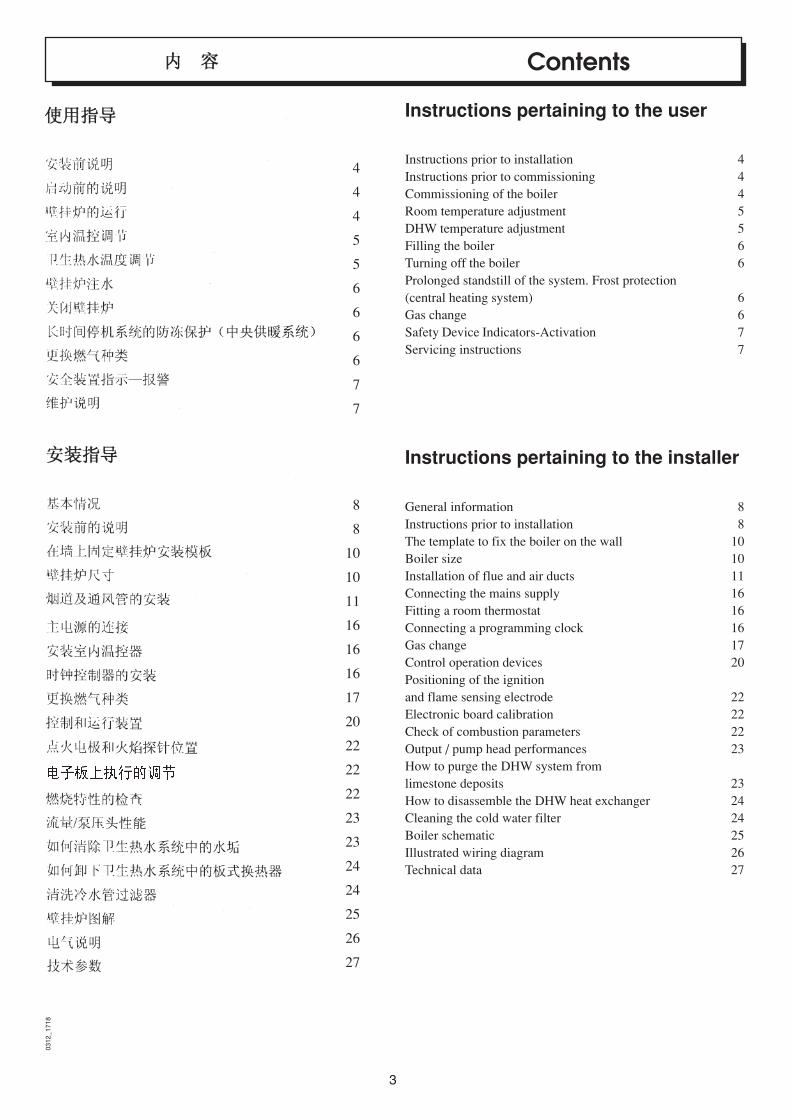
Contents
Instructions pertaining to the user
Instructions prior to installation 4Instructions prior to commissioning 4Commissioning of the boiler 4Room temperature adjustment 5DHW temperature adjustment 5Filling the boiler 6Turning off the boiler 6Prolonged standstill of the system. Frost protection(central heating system) 6Gas change 6Safety Device Indicators-Activation 7Servicing instructions 7
Instructions pertaining to the installer
General information 8Instructions prior to installation 8The template to fix the boiler on the wall 10Boiler size 10Installation of flue and air ducts 11Connecting the mains supply 16Fitting a room thermostat 16Connecting a programming clock 16Gas change 17Control operation devices 20Positioning of the ignitionand flame sensing electrode 22Electronic board calibration 22Check of combustion parameters 22Output / pump head performances 23How to purge the DHW system fromlimestone deposits 23How to disassemble the DHW heat exchanger 24Cleaning the cold water filter 24Boiler schematic 25Illustrated wiring diagram 26Technical data 27
4
4
4
5
5
6
6
6
6
7
7
8
8
10
10
11
16
16
16
17
20
22
22
22
23
23
24
24
25
26
27
4
0209
_240
1
Instructions pertaining to the user
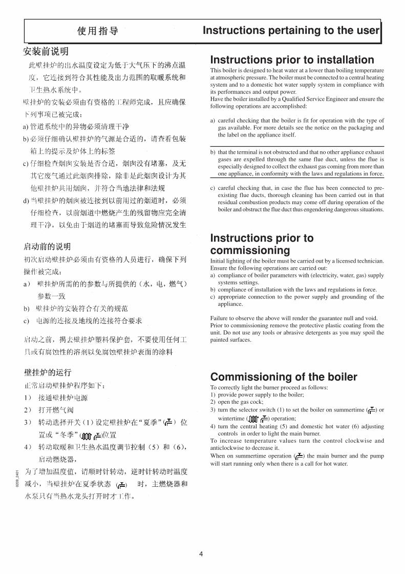
Instructions prior to installationThis boiler is designed to heat water at a lower than boiling temperatureat atmospheric pressure. The boiler must be connected to a central heatingsystem and to a domestic hot water supply system in compliance withits performances and output power.Have the boiler installed by a Qualified Service Engineer and ensure thefollowing operations are accomplished:
a) careful checking that the boiler is fit for operation with the type ofgas available. For more details see the notice on the packaging andthe label on the appliance itself.
b) that the terminal is not obstructed and that no other appliance exhaustgases are expelled through the same flue duct, unless the flue isespecially designed to collect the exhaust gas coming from more thanone appliance, in conformity with the laws and regulations in force.
c) careful checking that, in case the flue has been connected to pre-existing flue ducts, thorough cleaning has been carried out in thatresidual combustion products may come off during operation of theboiler and obstruct the flue duct thus engendering dangerous situations.
Instructions prior tocommissioningInitial lighting of the boiler must be carried out by a licensed technician.Ensure the following operations are carried out:a) compliance of boiler parameters with (electricity, water, gas) supply
systems settings.b) compliance of installation with the laws and regulations in force.c) appropriate connection to the power supply and grounding of the
appliance.
Failure to observe the above will render the guarantee null and void.Prior to commissioning remove the protective plastic coating from theunit. Do not use any tools or abrasive detergents as you may spoil thepainted surfaces.
Commissioning of the boilerTo correctly light the burner proceed as follows:1) provide power supply to the boiler;2) open the gas cock;3) turn the selector switch (1) to set the boiler on summertime ( ) or
wintertime ( ) operation;4) turn the central heating (5) and domestic hot water (6) adjusting
controls in order to light the main burner.To increase temperature values turn the control clockwise andanticlockwise to decrease it.When on summertime operation ( ) the main burner and the pumpwill start running only when there is a call for hot water.
( )
( )
( )

5
0209_3024
0210
_020
6
Figure 1
Figure 2
Warning: During initial lighting, until the air contained in the gas pipesis not released, the burner may fail to light immediately and that maycause a ‘blockage’ of the boiler. In this case we recommend you repeatthe ignition procedure until gas is delivered to the burner, setting selector(1) to ( ) for at least 1 second (see also figure 4).
Room temperature adjustmentThe system must be equipped with a room thermostat (see the relevantregulations) to control the temperature in the rooms.In case there is no room thermostat, during initial lighting it will bepossible to control the room temperature by turning control (5).To increase temperature values turn the control clockwise andanticlockwise to decrease it. Electronic modulation of the flame willenable the boiler to reach the set temperature by adapting the gas supplyto the burner to the actual heat exchange demand.
DHW temperature adjustmentThe gas valve is provided with an electronic flame-modulating function, which operates depending onthe DHW temperature adjusting control (6) settingsand on the quantity of water drawn from the taps.This electronic device allows to keep the watercoming out of the boiler at a constant temperaturealso when small quantities of water are drawn.
To ensure energy saving and economical manage-ment of your boiler, we recommend you place theswitch adjusting the hot water temperature on“comfort” (see figure 2). In wintertime it will benecessary to increase the DHW temperatureaccording to needs.
comfort zone
0403_0802

6
0210_0103/4/5
9909
2701
00
Boiler filling tap Boiler drain valveFigure 3
Filling the boilerImportant: Regularly check that the pressure displayed by the pressuregauge (7) is 0.5 to 1 bar, with boiler not operating. In case of overpressure,open the boiler drain valve.In case the pressure is lower open the boiler filling tap (figure 3).We recommend you open the tap very slowly in order to let off the air.In case pressure drops occur frequently have the boiler checked by aQualified Service Engineer.
The boiler is supplied with a hydraulic differential pressure sensor, whichblocks the boiler in case water is lacking or the pump is blocked.
Turning off the boilerTo turn off the boiler turn the selector switch (1) on (0); you will thusisolate the electrical supply to the boiler.
Prolonged standstill of the system.Frost protection (central heating system)We recommend you avoid draining the whole system as waterreplacements engender purposeless and harmful limestone deposits insidethe boiler and on the heating elements.In case the boiler is not operated during wintertime and is thereforeexposed to danger of frost we suggest you add some specific-purposeanti-freeze to the water contained in the system (e.g.: propylene glycolecoupled with corrosion and scaling inhibitors).
Gas changeThese boilers produced for natural gas can be converted to work withLPG.Any gas change must be effected by a Qualified Service Engineer.
7
0312_1601
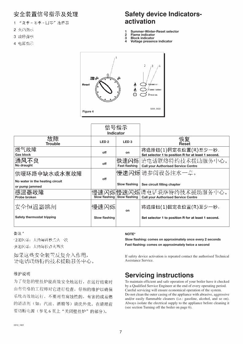
Figure 40209_3022
Safety device Indicators-activation1 Summer-Winter-Reset selector2 Flame indicator3 Block indicator4 Voltage presence indicator
If safety device activation is repeated contact the authorised TechnicalAssistance Service.
NOTE*
Slow flashing: comes on approximately once every 2 seconds
Fast flashing: comes on approximately twice a second
Servicing instructionsTo maintain efficient and safe operation of your boiler have it checkedby a Qualified Service Engineer at the end of every operating period.Careful servicing will ensure economical operation of the system.Do not clean the outer casing of the appliance with abrasive, aggressiveand/or easily flammable cleaners (i.e.: gasoline, alcohol, and so on).Always isolate the electrical supply to the appliance before cleaning it(see section Turning off the boiler on page 6).
Trouble
Gas block
No draught
No water in the heating circuit
or pump jammed
Probe broken
Safety thermostat tripping
Indicator
LED 2 LED 3
off on
offFast flashing
off
Slow flashing
Slow flashing Slow flashing
on
Slow flashing
Reset
Set selector 1 to position R for at least 1 second.
Call your Authorised Service Centre
See circuit filling chapter
Call your Authorised Service Centre
Set selector 1 to position R for at least 1 second.

8
0403
_110
1Instructions pertaining
to the installer
0209
_302
1
General information
Warning: When the selector switch (1) isset on Wintertime operation ( ) it maybe necessary to wait some minutes at eachintervention of the central heating tempera-ture adjusting control (5). To relight the mainburner immediately place the selector switch(1) on (0) and then again on ( ). Nowaiting is needed when the boiler is in theDHW mode on models with this option.
The following remarks and instructions are addressed to ServiceEngineers to help them carry out a faultless installation. Instructionsregarding lighting and operation of the boiler are contained in the‘Instructions pertaining to the user’ section.Note that installation, maintenance and operation of the domestic gasappliances must be performed exclusively by qualified personnel in com-pliance with current standards.Please note the following:* This boiler can be connected to any type of double- or single feeding
pipe convector plates, radiators, thermoconvectors. Design the systemsections as usual though taking into account the available output /pump head performances, as shown on page 23.
* Do not leave any packaging components (plastic bags, polystyrene,etc.) within children’s reach as they are a potential source of danger.
* Initial lighting of the boiler must be effected by a Qualified ServiceEngineer.
Failure to observe the above will render the guarantee null and void.
Instructions prior to installationThis boiler is designed to heat water at a lower than boiling temperatureat atmospheric pressure. The boiler must be connected to a central heatingsystem and, on models withis option, to a domestic hot water supplysystem in compliance with its performances and output power.Before connecting the boiler have the following operations effected:
a) careful checking that the boiler is fit for operation with the type ofgas available. For more details see the notice on the packaging andthe label on the appliance itself.
b) careful checking that the flue terminal draft is appropriate; that theterminal is not obstructed and that no other appliance exhaust gasesare expelled through the same flue duct, unless the flue is especiallydesigned to collect the exhaust gase coming from more than oneappliance, in conformity with the laws and regulations in force
c) careful checking that, in case the flue has been connected to pre-existing flue ducts, thorough cleaning has been carried out in thatresidual combustion products may come off during operation of theboiler and obstruct the flue duct thus engendering dangeroussituations.
9
To ensure correct operation of the appliance and avoid invalidating the
guarantee, observe the following precautions
1. Hot water circuit:
if the water hardness is greater than 20 °F (1 °F = 10 mg calcium carbonate
per litre of water) install a polyphosphate or comparable treatment system
responding to current regulations.
2. Heating circuit
2.1. new system
Before proceeding with installation of the boiler, the system must
be cleaned and flushed out thoroughly to eliminate residual thread-
cutting swarf, solder and solvents if any, using suitable proprietary
products.
2.2. existing system:
Before proceeding with installation of the boiler, the system must
be cleaned and flushed out to remove sludge and contaminants, using
suitable proprietary products.
To avoid damaging metal, plastic and rubber parts, use only neutral
cleaners, i.e. non-acid and non-alkaline (e.g. SENTINEL X400 and
X100), proceeding strictly in accordance with the maker’s directions.
Remember that the presence of foreign matter in the heating system can
adversely affect the operation of the boiler (e.g. overheating and noisy
operation of the heat exchanger)

10
0011
2111
00
The template to fix the boiler onthe wallDecide upon the boiler location, then tape the template on the wall.Connect the pipework to the gas and water inlets prearranged on thetemplate lower bar.We suggest you fit two G3/4 stop cocks (available on demand) on thecentral heating system flow and return pipework; the cocks will allow tocarry out important operations on the system without draining itcompletely.If you are either installing the boiler on a pre-existent system orsubstituting it, we suggest you also fit settling tanks on the system returnpipework and under the boiler to collect the deposits and scaling whichmay remain and be circulated in the system after the purge.When the boiler is fixed on the template connect the flue and air ducts(fittings supplied by the manufacturer) according to the instructions givenin the following sections.
0010
1712
00
Figure 5
MR: G3/4 heating flowUS: G1/2 domestic hot water outletGAS: G3/4 gas inlet to the boilerES: G1/2 cold water inletRR: G3/4 heating return
Figure 6
9910
0703
00
0209
_302
0
Boiler size
11
0011211200
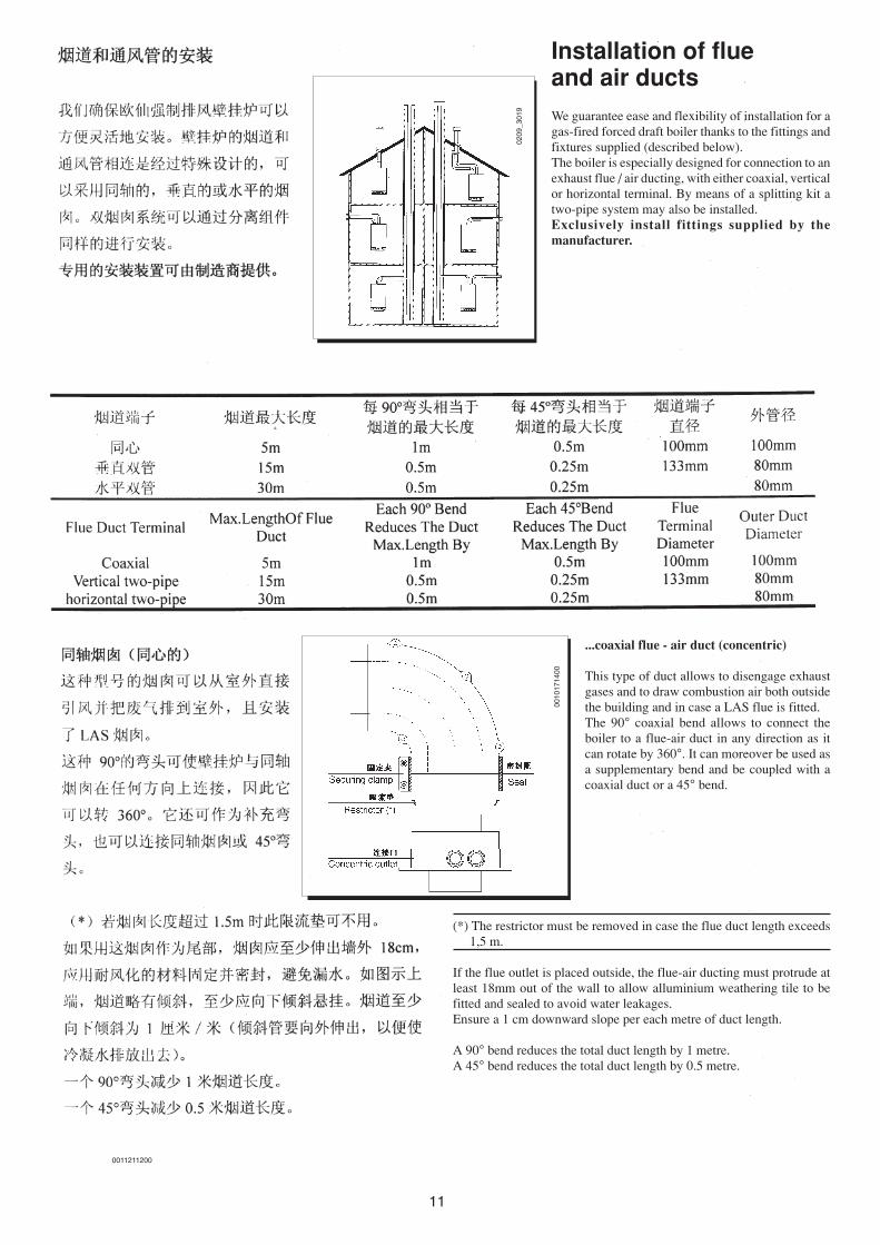
Installation of flueand air ductsWe guarantee ease and flexibility of installation for agas-fired forced draft boiler thanks to the fittings andfixtures supplied (described below).The boiler is especially designed for connection to anexhaust flue / air ducting, with either coaxial, verticalor horizontal terminal. By means of a splitting kit atwo-pipe system may also be installed.Exclusively install fittings supplied by themanufacturer.
...coaxial flue - air duct (concentric)
This type of duct allows to disengage exhaustgases and to draw combustion air both outsidethe building and in case a LAS flue is fitted.The 90° coaxial bend allows to connect theboiler to a flue-air duct in any direction as itcan rotate by 360°. It can moreover be used asa supplementary bend and be coupled with acoaxial duct or a 45° bend.
(*) The restrictor must be removed in case the flue duct length exceeds1,5 m.
If the flue outlet is placed outside, the flue-air ducting must protrude atleast 18mm out of the wall to allow alluminium weathering tile to befitted and sealed to avoid water leakages.Ensure a 1 cm downward slope per each metre of duct length.
A 90° bend reduces the total duct length by 1 metre.A 45° bend reduces the total duct length by 0.5 metre.
0209
_301
9
0010
1714
00

12
Horizontal flue terminal installation options
L max = 5 mL max = 5 m
L max = 4 m
L max = 4 m
L max = 5 m
LAS flue duct installation options
0209
_301
802
09_3
017
0010171500

13
0010171700
L max = 4 m L max = 4 m L max = 3 mL max = 2 m
Vertical flue terminal installation options
This type of installation can be carried out both on a flat or pitched roofby fitting a terminal, an appropriate weathering tile and sleeve,(supplementary fittings supplied on demand).
For detailed instructions concerning the installation of fittings refer tothe technical data accompanying the fittings.
… separated flue-air ducting
This type of ducting allows to disengage exhaust flue gases both outsidethe building both into single flue ducts.Comburant air may be drawn in at a different site from where the flueterminal is located.The splitting kit consists of a flue duct adaptor (100/80) and of an airduct adaptor; the latter may be placed either on the left or on the right ofthe flue terminal according to installation requirements.For the air duct adaptor fit the screws and seals previously removedfrom the cap.The restrictor must be removed in case you install separated flue and airduct terminals.
The 90° bend allows to connect the boiler to flue-air ducting regardlessof direction as it can be rotated by 360°. It can moreover be used as asupplementary bend to be coupled with the duct or with a 45° bend.
0209
_301
600
1017
1600
14
(L1 + L2) max = 30 m (L1 + L2) max = 30 m
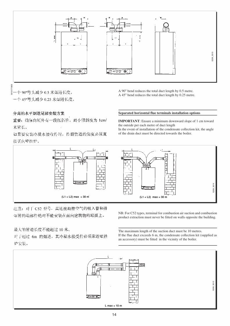
A 90° bend reduces the total duct length by 0.5 metre.A 45° bend reduces the total duct length by 0.25 metre.
Separated horizontal flue terminals installation options
IMPORTANT: Ensure a minimum downward slope of 1 cm towardthe outside per each metre of duct lengthIn the event of installation of the condensate collection kit, the angleof the drain duct must be directed towards the boiler.
L max = 10 m
NB: For C52 types, terminal for combustion air suction and combustionproduct extraction must never be fitted on walls opposite the building.
The maximum length of the suction duct must be 10 metres.If the flue duct exceeds 6 m, the condensate collection kit (supplied asan accessory) must be fitted in the vicinity of the boiler.
0209
_301
502
09_3
014
0209
_301
3
0010
1718
00
15
0010
1719
00
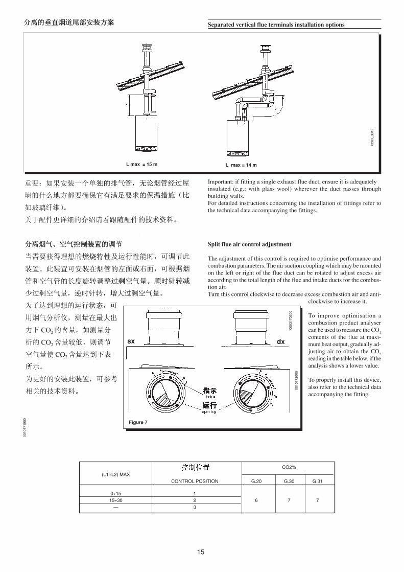
L max = 14 mL max = 15 m
Separated vertical flue terminals installation options
Important: if fitting a single exhaust flue duct, ensure it is adequatelyinsulated (e.g.: with glass wool) wherever the duct passes throughbuilding walls.For detailed instructions concerning the installation of fittings refer tothe technical data accompanying the fittings.
Split flue air control adjustment
The adjustment of this control is required to optimise performance andcombustion parameters. The air suction coupling which may be mountedon the left or right of the flue duct can be rotated to adjust excess airaccording to the total length of the flue and intake ducts for the combus-tion air.Turn this control clockwise to decrease excess combustion air and anti-
clockwise to increase it.
To improve optimisation acombustion product analysercan be used to measure the CO
2
contents of the flue at maxi-mum heat output, gradually ad-justing air to obtain the CO
2
reading in the table below, if theanalysis shows a lower value.
To properly install this device,also refer to the technical dataaccompanying the fitting.
0209
_301
2
0003
1702
00
Figure 7
sx dx
0010
1720
00
CO2%
(L1+L2) MAXCONTROL POSITION G.20 G.30 G.31
0÷15 115÷30 2 6 7 7
— 3
16
Figure 9
9402
2507
15
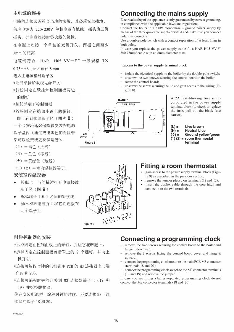
Connecting the mains supplyElectrical safety of the appliance is only guaranteed by correct grounding,in compliance with the applicable laws and regulations.Connect the boiler to a 230V monophase + ground power supply bymeans of the three-pin cable supplied with it and make sure you connectpolarities correctly.Use a double-pole switch with a contact separation of at least 3mm inboth poles.In case you replace the power supply cable fit a HAR H05 VV-F’3x0.75mm2 cable with an 8mm diameter max.
…access to the power supply terminal block
• isolate the electrical supply to the boiler by the double-pole switch;• unscrew the two screws securing the control board to the boiler;• rotate the control board;• unscrew the screw securing the lid and gain access to the wiring (Fi-
gure 8).
A 2A fast-blowing fuse is in-corporated in the power supplyterminal block (to check or replacethe fuse, pull out the black fusecarrier).
(L) = Live brown(N) = Neutral blue( ) = Ground yellow/green(1) (2) = room thermostat
terminalFigure 8
0010
1721
00
Fitting a room thermostat• gain access to the power supply terminal block (Figu-
re 9) as described in the previous section;• remove the jumper placed on terminals (1) and (2);• insert the duplex cable through the core hitch and
connect it to the two terminals.
Connecting a programming clock• remove the two screws securing the control board to the boiler and
hinge it downward;• remove the 2 screws fixing the control board cover and hinge it
upward;• connect the programming clock motor to the main PCB M3 connector
(terminals 18 and 20);• connect the programming clock switch to the M3 connector terminals
(17 and 19) and remove the jumper.In case you are fitting a battery-operated programming clock do notconnect the M3 connector terminals (18 and 20).
0402_0504
17
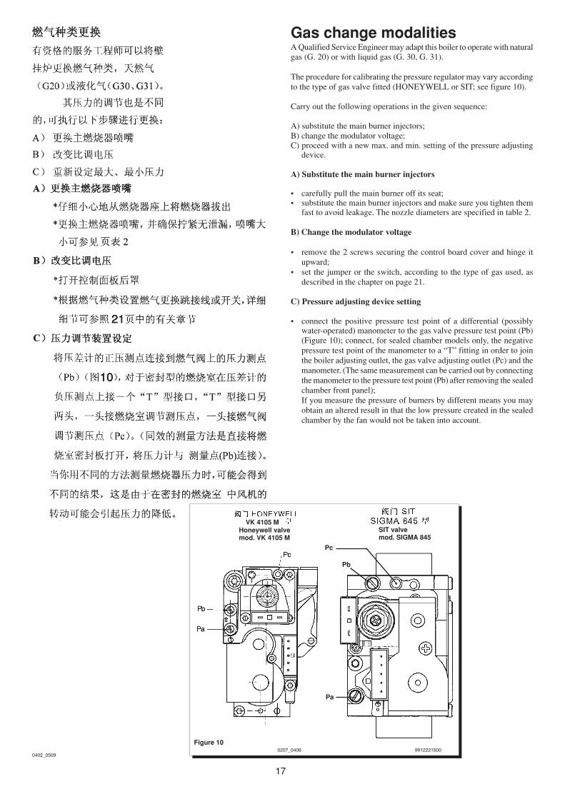
Gas change modalitiesA Qualified Service Engineer may adapt this boiler to operate with naturalgas (G. 20) or with liquid gas (G. 30, G. 31).
The procedure for calibrating the pressure regulator may vary accordingto the type of gas valve fitted (HONEYWELL or SIT; see figure 10).
Carry out the following operations in the given sequence:
A) substitute the main burner injectors;B) change the modulator voltage;C) proceed with a new max. and min. setting of the pressure adjusting
device.
A) Substitute the main burner injectors
• carefully pull the main burner off its seat;• substitute the main burner injectors and make sure you tighten them
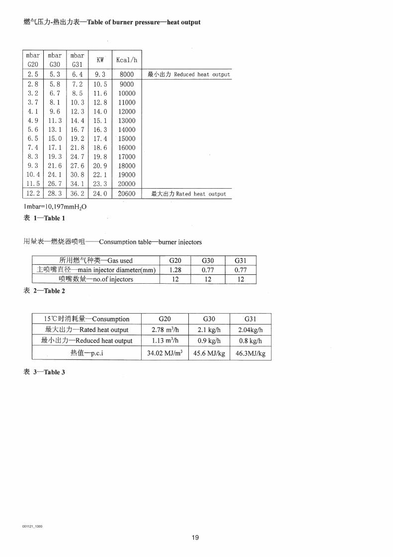
fast to avoid leakage. The nozzle diameters are specified in table 2.
B) Change the modulator voltage
• remove the 2 screws securing the control board cover and hinge itupward;
• set the jumper or the switch, according to the type of gas used, asdescribed in the chapter on page 21.
C) Pressure adjusting device setting
• connect the positive pressure test point of a differential (possiblywater-operated) manometer to the gas valve pressure test point (Pb)(Figure 10); connect, for sealed chamber models only, the negativepressure test point of the manometer to a “T” fitting in order to jointhe boiler adjusting outlet, the gas valve adjusting outlet (Pc) and themanometer. (The same measurement can be carried out by connectingthe manometer to the pressure test point (Pb) after removing the sealedchamber front panel);If you measure the pressure of burners by different means you mayobtain an altered result in that the low pressure created in the sealedchamber by the fan would not be taken into account.
SIT valvemod. SIGMA 845
Figure 10
Honeywell valvemod. VK 4105 M
99122215000207_0406
Pc
Pb
Pa
0402_0509
VK 4105 M
18
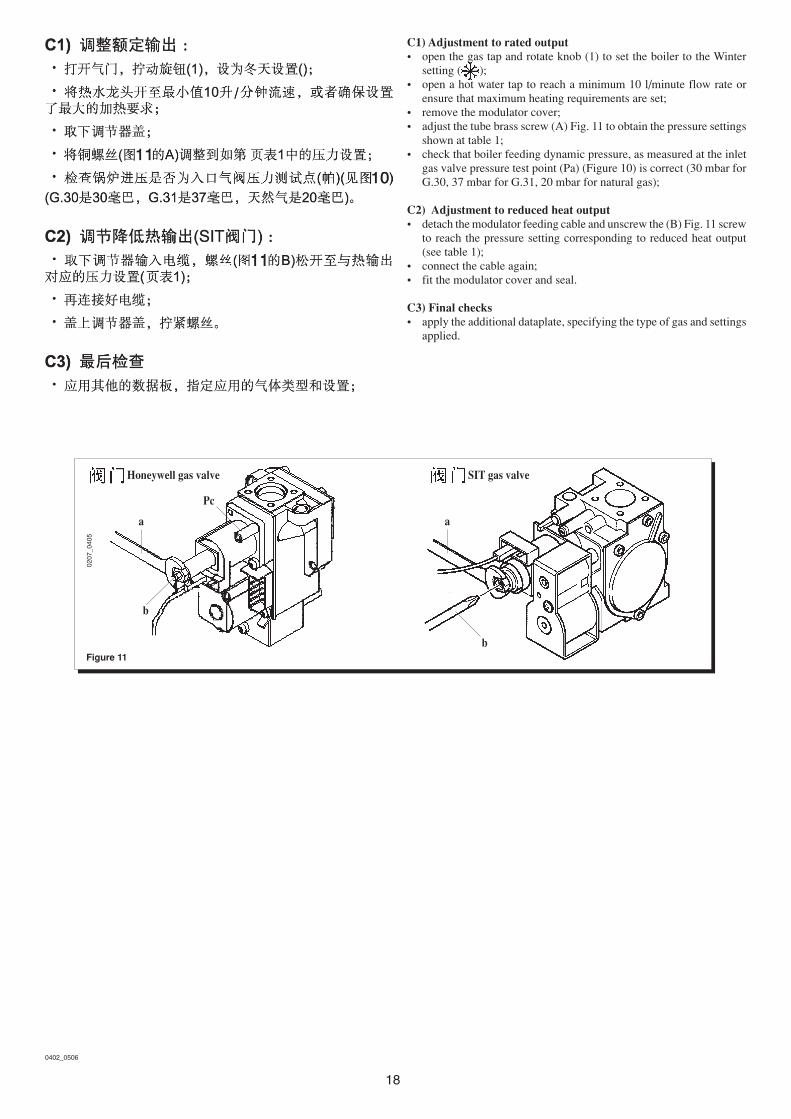
Figure 11
0207
_040
5
Honeywell gas valve SIT gas valve
aa
b
b
Pc
C1) Adjustment to rated output• open the gas tap and rotate knob (1) to set the boiler to the Winter
setting ( );• open a hot water tap to reach a minimum 10 l/minute flow rate or
ensure that maximum heating requirements are set;• remove the modulator cover;• adjust the tube brass screw (A) Fig. 11 to obtain the pressure settings
shown at table 1;• check that boiler feeding dynamic pressure, as measured at the inlet
gas valve pressure test point (Pa) (Figure 10) is correct (30 mbar forG.30, 37 mbar for G.31, 20 mbar for natural gas);
C2) Adjustment to reduced heat output• detach the modulator feeding cable and unscrew the (B) Fig. 11 screw
to reach the pressure setting corresponding to reduced heat output(see table 1);
• connect the cable again;• fit the modulator cover and seal.
C3) Final checks• apply the additional dataplate, specifying the type of gas and settings
applied.
0402_0506
19
001121_1300
20
0403_0807
Control and operation devicesThe boiler has been designed in full compliance with European referencestandards and in particular is equipped with the following:
• Central heating temperature adjustment potentiometerThis potentiometer sets the central heating flow max. temperature.Its temperature range goes from 30 °C min. to 85 °C max.To increase the temperature turn knob (5) clockwise and anticlockwiseto decrease it.
• Domestic hot water temperature adjusting potentiometerThis potentiometer sets the domestic hot water max. temperature. Itstemperature range goes from 35 °C min. to 65 °C max according tothe water inlet flow rate.To increase the temperature turn knob (6) clockwise and anticlockwiseto decrease it.
• Air pressure switchThis switch allows the main burner to switch on provided the exhaustflue duct efficiency is perfect.In the event of one of the following faults:• the flue terminal is obstructed• the venturi is obstructed• the fan is blocked• the connection between the venturi and the air pressure switch is
not activethe boiler will remain on standby and LED 3 will flash at highfrequency.
The fan’s electric power supply is cut off if the air pressure switchfails to provide a signal within a time of 10 minutes.Momentarily move the selector ( 1 ) onto ( 0 ) to restore operation.
• Safety thermostatThis device, which is connected to a sensor on the central heatingdelivery line, cuts off the flow of gas to the burner if the water in theprimary circuit overheats. In these conditions the boiler locks out(LED 2 flashes slowly) and can be relit, by turning selector (1) toposition ( ) for at least 1 second, only after the cause of the problemhas been removed.
Disabling this safety device is forbidden
• Flame ionization detectorThe flame sensing electrode, placed on the right of the burner,guarantees safety of operation in case of gas failure or incompleteinterlighting of the main burner.Under such conditions the boiler is blocked (LED 3 illuminated).Turn selector (1) to position ( ) for at least 1 second to restorenormal operating conditions.
If there is no gas, the unit makes 3 attempts at igniting the burnerwith a 25-second pause between each attempt.The unit shuts down if the burner fails to ignite after three attempts(LED 3 illuminated).
0403
_080
504
03_0
806

21
0403_0808
• Hydraulic differential pressure sensorThis pressure sensor, fitted on the hydraulic assembly, allows themain burner to light provided the pump head is as required and protectsthe flue-water exchanger from possible lacks of water or blockingsof the pump (LED 3 flashes slowly).
• Hydraulic safety valve (heating circuit)This device is set to 3 bar and is used for the heating circuit.
The safety valve should be connected to a siphoned drain. Use a a meansof draining the heating circuit is strictly prohibited.
22
0312
_170
2
Figure 12
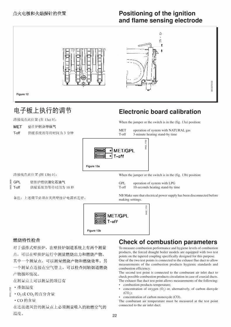
Positioning of the ignitionand flame sensing electrode
Check of combustion parametersTo measure combustion performance and hygiene levels of combustionproducts, the forced draught boiler models are equipped with two testpoints on the tapered coupling specifically designed for this purpose.One of the two test points is connected to the exhaust flue duct to allowmeasurements of the combustion products hygienic standards andcombustion efficiency.The second test point is connected to the comburant air inlet duct tocheck possible combustion products circulation in case of coaxial ducts.The exhaust flue duct test point allows measurements of the following:• combustion products temperature;• concentration of oxygen (O
2) or, alternatively, of carbon dioxyde
(CO2);
• concentration of carbon monoxyde (CO).The comburant air temperature must be measured at the test pointconnected to the air inlet duct.
9912
0701
00
Electronic board calibration
When the jumper or the switch is in the (fig. 13a) position:
MET operation of system with NATURAL gasT-off 3-minute heating stand-by time
When the jumper or the switch is in the (fig. 13b) position:
GPL operation of system with LPGT-off 10-seconds heating stand-by time
NB Make sure that electrical power supply has been disconnected beforemaking settings.
Figure 13b
Figure 13a
0403
_080
9
0402
_170
204
02_1
701

23
0209
_301
1
OUTPUT l/hGraph 1
PU
MP
HE
AD
mH
2O
Output / pump headperformancesThis is a high static head pump fit for installation on any type of singleor double-pipe heating systems. The air vent valve incorporated in thepump allows quick venting of the heating system.
How to purge the DHW systemfrom limestone depositsTo clean the DHW system it is not necessary to remove the DHW heatexchanger if the assembly is equipped with the appropriate taps (suppliedon demand) placed on the hot water outlet and inlet.
To carry out the purge it is necessary to:• close the cold water inlet• drain the DHW system from the water contained therein by means of
a hot water tap• close the DHW outlet• unscrew the two stop cocks caps• remove the filters.
In case the appropriate tap is not supplied it is necessary to disassemblethe DHW heat exchanger, as described in the following section, and dothe purge aside. We recommend you also purge from limestone depositsthe DHW heat exchanger seat and the NTC sensor fitted on the DHWsystem.
0209
_301
0
LUNA 240 i - 240 Fi
24
0011
2116
00
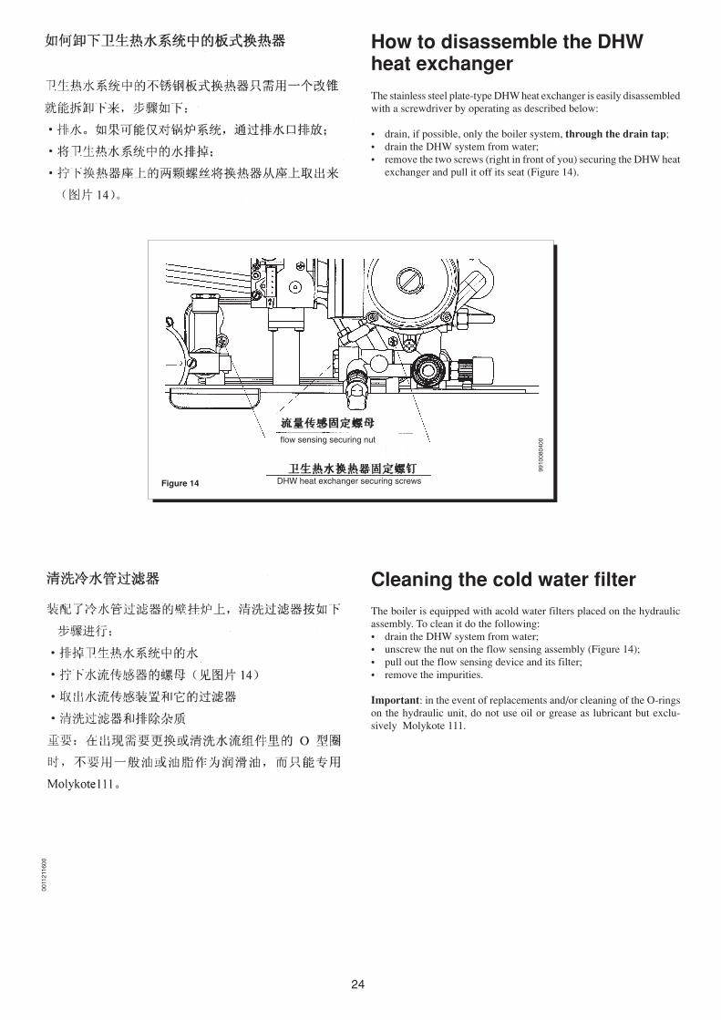
Figure 14 DHW heat exchanger securing screws
flow sensing securing nut
9910
0804
00
How to disassemble the DHWheat exchanger
The stainless steel plate-type DHW heat exchanger is easily disassembledwith a screwdriver by operating as described below:
• drain, if possible, only the boiler system, through the drain tap;• drain the DHW system from water;• remove the two screws (right in front of you) securing the DHW heat
exchanger and pull it off its seat (Figure 14).
Cleaning the cold water filterThe boiler is equipped with acold water filters placed on the hydraulicassembly. To clean it do the following:• drain the DHW system from water;• unscrew the nut on the flow sensing assembly (Figure 14);• pull out the flow sensing device and its filter;• remove the impurities.
Important: in the event of replacements and/or cleaning of the O-ringson the hydraulic unit, do not use oil or grease as lubricant but exclu-sively Molykote 111.

25
Boiler schematic PERFORMA 24
0209
_090
4
Key:7 pressure gauge8 gas service cock9 cold water inlet on/off valve and filter
10 diverter valve assembly11 DHW flow priority assembly12 hydraulic differential pressure sensor13 flow sensor with filter14 automatic by-pass15 plate-type DHW heat exchanger16 boiler filling tap17 boiler drain point18 pressure relief valve19 DHW flow priority microswitch20 hydraulic differential pressure sensor microswitch21 pump and air separator22 automatic air vent23 DHW NTC sensor24 overheat thermostat25 expansion vessel26 gas valve27 burner injector28 main burner29 ignition electrode30 flame sensing electrode31 flue-water exchanger32 flue hood33 fan34 air pressure switch35 positive pressure point36 negative pressure point37 flue adaptor
Figure 15
heating domestic water gas domestic water heatingdelivery outlet inlet return
0402
_050
7
26
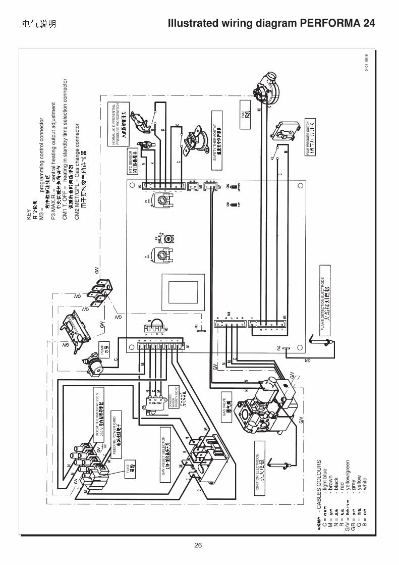
Illustrated wiring diagram PERFORMA 24K
EY
M3
=pr
ogra
mm
ing
cont
rol c
onne
ctor
P3
MA
X.R
. =ce
ntra
l hea
ting
outp
ut a
djus
tmen
t
CM
1 T.
OF
F =
heat
ing
in s
tand
by ti
me
sele
ctio
n co
nnec
tor
CM
2 M
ET
/GP
L =
Gas
cha
nge
conn
ecto
r
- C
AB
LES
CO
LOU
RS
C =
- lig
ht b
lue
M =
- br
own
N =
- bl
ack
R =
- re
dG
/V =
- ye
llow
/gre
enG
R =
- gr
eyG
=-
yello
wB
=-
whi
te04
01_0
916
FAN
IGN
ITIO
N E
LEC
TR
OD
E
GA
S V
ALV
E
S/W
-R
ES
ET
SE
LEC
TO
R
PU
MP
FU
SE
FE
ED
ING
PO
WE
R G
RID
RO
OM
TH
ER
MO
STA
T 2
30 V
230
V
DO
ME
STI
CW
ATE
RP
RIO
RIT
Y M
ICR
O
HID
RA
ULI
C D
IFF
ER
EN
TIA
LP
RE
SS
UR
E M
ICR
OS
WIT
CH
SA
FE
TY
TH
ER
MO
STA
T
NT
C S
EN
SO
R FLUE
PRE
SSUR
E SW
ITCH
FLA
ME
DE
TE
CT
ION
ELE
CT
RO
DE

27
0210
_010
1
Technical dataPERFORMA 24
DECLARATION OF CONFORMITY
POTTERTON declares that this wall hung gas boiler is made in compliance to the following European Standards:
EN 435EN 483EN 625EN 60 335-1EN 50165EN 60529EN 61000EN 55014
POTTERTON also declares that this appliance is tested:
• in heating and sanitary mode working with gas;• with a pressure of 12 bar on the hydraulic sanitary circuit;• with a pressure of 4,5 bar on the hydraulic heating circuit;• with an electrical safety control in compliance to the European Standards EN 60 335-1.
0209
_300
8
POTTERTON
POTTERTON


Ediz. 1 - 03/04
Potterton, Baxi UK Limited, Brownedge Road, Bamber Bridge, Preston, Lancashire. PR5 6SNAfter Sales Service 08706 096 096 Technical Enquiries 08706 049 049
www.baxi.com
923.345.1
Related Documents