LA-UR-90-3230 Perchecj Zone Monitoring Well Installation by W.O. Purtymun and A.K. Stoker Environmental Protection Group (HSE-8) Los Alamos National Laboratory September, 1990 11111111111111111111111111111111111 122()2

Welcome message from author
This document is posted to help you gain knowledge. Please leave a comment to let me know what you think about it! Share it to your friends and learn new things together.
Transcript

LA-UR-90-3230
Perchecj Zone Monitoring Well Installation
by
W.O. Purtymun and A.K. Stoker
Environmental Protection Group (HSE-8)
Los Alamos National Laboratory
September, 1990
11111111111111111111111111111111111 122()2
..
PERCHED ZONE MONITORING WELL INSTALLATION
I. INTRODUCTION
by W. D. Purtymun and A. K. Stoker
Environmental Protection Group (HSE-8)
Los Alamos National Laboratory September 1990
The Hazardous Waste Pennit (Hazardous and Solid Waste Amendments, 1984) issued to the United States Department of Energy (owner) and the University of California (operator) contains several Special Conditions in Module VIII, Sec. C. The first condition relates to Perched Zone Monitoring. This condition required the installation of monitoring wells or borings in the principal canyons of the Pajarito Plateau as follows: Pueblo Canyon (one exploratory boring); Los Alamos Canyon (three monitoring wells near existing wells LA0-3, LA0-4.5, and LA0-5); Sandia Canyon (two monitoring wells near water supply wells PM-1 and PM-3); Mortandad Canyon (three monitoring wells near existing wells MC0-4, MC0-6, and MC0-7); Potrillo Canyon (one monitoring well near State Road 4); Fence Canyon (one monitoring well near State Road 4); and Water Canyon (three monitoring wells: one near State Road 4, one 1 mile west of State Road 4, and one 2 miles west of State Road 4). Water samples will be collected from the wells in September 1990 and analyzed for specific constituents in accordance with the timetable specified in the pennil
These canyons were created by southeast-trending intennittent streams that have cut deeply into the surface of the plateau. The intennittent stream flow has eroded, transported, and deposited alluvium in the stream channel of these canyons. The origin of the drainage area of the canyons detennines the general type of alluvium. Canyons that head on the flanks of the mountains west of the plateau contain mainly sands, gravels, cobbles, and boulders derived from dense, hard rock eroded from the flanks of the mountains. These canyons include three specified in the special condition: Pueblo, Los Alamos, and Water. Canyons that head on the plateau contain clays, silts, sands, and some gravels derived from the softer tuff that fonns the plateau. These canyons include four specified in the special condition: Sandia, Mortandad, Potrillo, and Fence.
The shallow aquifers in the alluvium of the canyons is in the sands, gravels, cobbles, and boulders of canyons heading on the mountains or in the reworiced and weathered clays, silts, sands, and gravels of canyons heading on the plateau.
1

W. D. Purtymun and A. K. Stoker
PERCHED ZONE MONITORING WELL INSTALLA T/ON los Alamos National laboratory
September 1990
The aquifers in the alluvium exist as a narrow ribbon of saturation along the canyon bottoms and are perched on the underlying silts and clays. The aquifers are of limited horizontal extent and are dependent on surface water for recharge. The spring snowmelt run-off causes water levels in the aquifer to rise and the aquifer to advance down the canyon. In early summer, the water levels typically decline and the aquifers retreat up the canyon. Summer run-off causes the water levels to nse and aquifers to advance down the canyon; the lack of run-off in the fall and winter causes the water level to decline and the aquifer to retreat up the canyon. These same hydrologic effects take place in canyons that also receive treated industrial and/or sanitary effluents. Thus, dependent on the amount of recharge, the thickness of the saturated part of the aquifer will vary and at times may be dry. 1be water levels in an aquifer may vary by 10 or more feet in the course of a year.
II. WELL DRILLING AND COMPLETION
All of the wells or borings were drilled and completed using the same basic equipment and methods. The methods generally followed the recommendations of the Resource Conservation and Recovery Act (RCRA) Ground-Water Monitoring Technical Enforcement Guidance Document (TEGD) to the extent practicable and allowing for some modifications based on more than 40 years of experience with monitoring initiated by the U.S. Geological Survey. These methods are described in this section and are applicable to all of the wells. Details of each individual well completion are provided in individual figures discussed later in this repon. A pilot hole was drilled with either a standard continuous-flight auger (4.5 in. diameter) or cored with a hollow-stem auger (7.25-in. hole diameter). The depth to the base of the aquifer was determined by the cuttings and drilling pressure or by direct inspection of the continuous core retrieved from the hole.
The characteristics of the alluvium (hole collapse) require construction of the well through a hollow-stem auger. Accordingly, the pilot hole provided a guide for reaming the hole using a larger diameter hollow-stem auger (6.25 in. i.d., 9.625 in. o.d., with a 10.375-in. o.d. bit). This bit was run in the pilot hole with a knockout plate, and the auger joints were equipped with 0-Ring seals. The hole was reamed below the base of the aquifer.
If water was encountered in the pilot hole, it was necessary to fill the 6.25-in. i.d. hollow-stem auger with water to a level equal to the top of the aquifer to keep sands and gravels from running into the hollow stem when the plate in the bit was knocked out The plate was knocked out and the auger raised 0.5 to 1.0 ft to anchor the casing on the bottom of the hole. The 2-in.-diameter casing was set through the hollow stem and rested on the plate. The lowest portion of the casing consisted of one or two 10-ft lengths of screen with a plug at the bottom. (In
2

W. D. Purtymun and A. K. Stoker
PERCHED ZONE MONITORING WELL INSTALLATION Los Alamos National Laboratory
September 1990
three wells, a 5-ft blank section was extended below the screen to provide for -bailer descent to assist in collecting adequate sample volumes.)
The annulus between the hollow-stem auger and casing screen was filled with the gravel pack (sand) in increments of 2 to 3 ft, at which time the auger was pulled up a corresponding amount Keeping the sand in the auger while raising the auger assured a continuous gravel pack between the borehole wall and the screen by preventing :aty fonnation material from caving in around the casing. Accordingly, this method is believed to be preferable to using a tremie after removal of the entire length of auger. The gravel pack was continued up to a point 2 to 3 ft above the top of the screened section. At this point, a seal of bentonite and/or cement was extended to the surface using the same method of emplacement through the auger to assure a continuous seal with no formation material collapsing in around the blank tubing.
At a depth of about 3 to 5 ft, the auger was removed from the hole. The upper part of the well was filled with cement and the wellhead security cap was set about 1.5 to 2 ft into the cement. A brass cap was set in a 2-ft-square concrete pad poured around the wellhead security cap.
Ill. WELL CONSTRUCTION MATERIALS
The materials used in well construction include the casing, the sand or gravel pack, the bentonite seal material, and cement Also considered as part of the construction is the wellhead security cap that pennits only authorized personnel to access the well for water-level measurements or sampling.
The casing, screen, plugs, and caps were made of polyvinyl chloride (PVC), using flush-joint, internal, upset-threaded-type connections. The casing and screen were 2 in. i.d. (2.375 in. o.d.), in 5- or 10-ft lengths. The screen openings were 0.010 in. The casing, screen, plugs, and caps were manufactured by TIMCO Manufacturing, Inc. (85115th Street, Prairie Du Sac, Wisconsin 53578, phone 608-643-8534).
The sand used for the gravel pack was sized from 0.010 to 0.020 in. and is compatible with the screen openings in the casing of 0.010 in. Because of the nature of the aquifer material (very fine suspended particles), the smallest screen opening and appropriate size gravel pack were used. 'The sand used as a gravel pack carne in 50- or 100-lb bags. The 100-lb bag contained about 0.97 ft3 of pure Colorado silica sand. 'The sand was processed and marketed by Silica Sand, Inc. (P.O. Box 15615, Colorado Springs, Colorado 80935).
The bentonite was brand name Hole Plug, coarse-grade Wyoming bentonite, and was supplied in 50-lb bags, 0.69 ft3 per bag (dry), and was marketed by Baroid Division (N.L. Petroleum Surveys, Inc., P.O. Box 1675, Houston, Texas).
3

W. D. Purtymun and A. K. Stoker
PERCHED ZONE MONITORING WELL INSTALLATION Los Alamos National laboratory
September 1990
A premix cement (1 to 5) was used to seal part of the hole and to construct the wellhead and accompanying security cap. The cement mix came in 60-lb bags, about 0.5 ft3 per bag. The brand name of the mixture was Quikrete, marketed by the Quikrete Company, Atlanta, Georgia 30234.
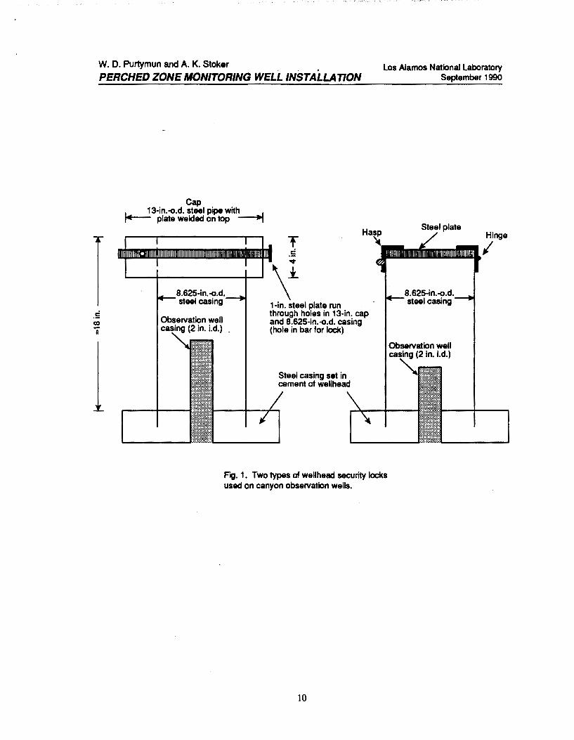
Two types of well security caps were used in completion of the observation wells. The first type was a standard 8.625-in. o.d. steel casing set into the cement 1be top of the casing was secured with a hinged plate and hasp welded to the casing. The other type of well security was the 8.625-in. o.d. steel casing set into the cement, covered by a removable "mushroom" cap made from a 13-in. steel casing about 0.5 ft long with a steel plate welded to one end. 'The 13-in. casing with cap was set on the 8.625-in. casing. Slots cut through the side of the cap and the casing were aligned to receive a steel bar that secures the cap to the top of the casing. A hole through the bar allows a lock to secure the cap and prevent removal of the bar. Both types of caps are shown in Fig. 1.
IV. WELL DEVELOPMENT
Well development was carried out using several techniques in combination. However, none of the wells that have water in them has yet been able to meet the turbidity requirement of 5 nephelometric turbidity units. This was as expected, based on previous experience with the 25- to 30-year-old U.S. Geological Survey wells, which still yield samples with considerable turbidity. The turbidity results from the fine suspended clays and silts found in the aquifer. These clays and silts are derived from weathering of the ash matrix of the tuff. As a result, the smallest size screen generally available from commercial sources (0.010 in.), with matched sand size (0.010 to 0.020 in.), was used in completing all the new wells. The presence of these suspended sediments and the fluctuation of the thickness of the aquifer have hampered or prevented well development, even without suspended sediments entering the wells during bailing.
The wells were developed using a surge block, pumping, bailing, and jetting. At least two methods were used in each well. 'The choice of methods depended on the depth to water and observations of the saturated thickness. Jetting was the most commonly used method and was applied to all of the Mortandad and Los Alamos canyon wells. The Pueblo Canyon well was developed mainly by pumping.
V. OBSERVATION WELLS
The observation well elevations, measuring points (MPs), and coordinates (New Mexico State Plane system) are shown in Table I. Well characteristics are presented in Table ll. The log, casing schedule, and construction details for each well are found in Figs. 2 through 15. Locations of the observation wells and
4
W. D. Purtymun and A. K. Stoker
PERCHED ZONE MONITORING WELL INSTALLATION Los Alamos National Laboratory
September 1990
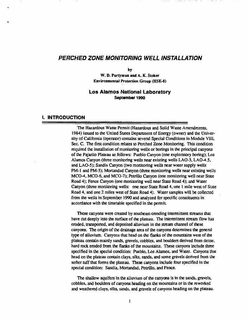
holes are indicated in Fig. 16. The map in Fig. 16 also shows locations of -existing monitoring wells that indicate the extent of perched ground water in the canyon alluvial systems. Some alluvial perched ground water can also be inferred to exist in portions of canyons within the facility boundaries where surface stream flow occurs throughout the year. These canyons include the portion of Pueblo Canyon (fed by effluent from the Los Alamos County sanitary sewage treatment plant), Los Alamos Canyon (fed by flow from the mountains and released from the reservoir), Sandia Canyon (fed by effluent from the TA-3 sanitary sewage treatment plant), Pajarito Canyon (fed by surface run-off from the mountains to the west), and Water Canyon (fed by springs on the flanks of the mountains to the west). These locations are generally funher upstream than any of the new monitoring wells, as can be seen by the locations of old monitoring wells that contain water in Los Alamos and Pajarito Canyons (see Fig. 16).
The wells were located along the eastern third of the plateau. Seven of wells were dry when drilled, and three additional wells (two in Mortandad Canyon and one in Los Alamos Canyon) became dry during the summer because of the lack of surface run-off. Two additional wells were drilled in Mortandad Canyon because the old U.S. Geological Survey wells indicated that the water level had declined beneath the lowest part of the 10-ft screen installed in the first new wells. The replacement wells were equipped with 20-ft screen sections to allow for the considerable fluctuation in water level. The well in Los Alamos Canyon that is now dry was completed into the top of the underlying basalt, and the aquifer has receded upstream because of limited recharge from run-off. Details of individual wells are discussed below or are shown in the referenced figures.
A. Pueblo Canyon
Pueblo Canyon observation well APC0-1 was completed in alluvium underlain by siltstone and claystone. Water was perched in the alluvium (Fig. 2).
B.LosAkunosCanyon
Los Alamos Canyon observation well LA0-3A was completed in alluvium underlain by tuff. Water was perched on the weathered tuff (Fig. 3).
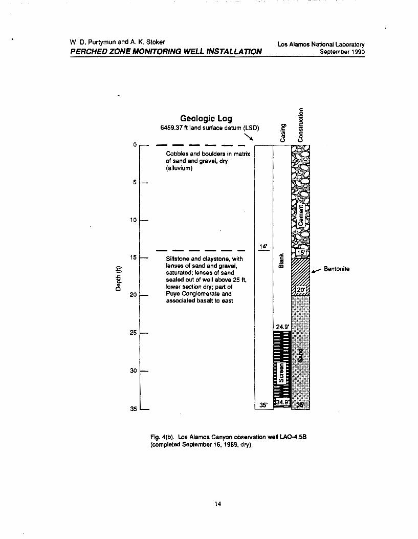
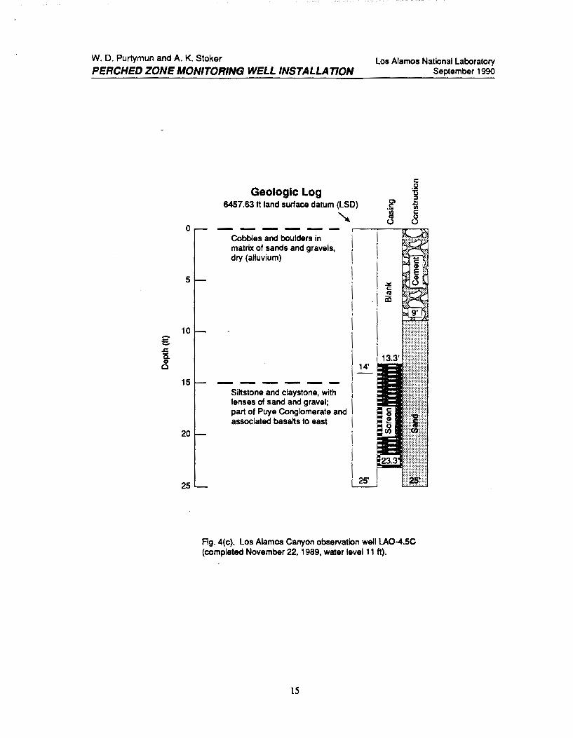
Three wells were completed near LA0-4.5. Two of the wells were dry but were completed as wells because there is a possibility of the alluvium or sand lens in the underlying siltstone and claystone becoming saturated with an increase of stonn run-off [Fig. 4(a) and 4(b)]. The siltstone and claystone underlying the alluvium is associated with the basalt that underlies the alluvium to the east Water occurs in a sand lens within the siltstone and claystone [Fig. 4(c)].
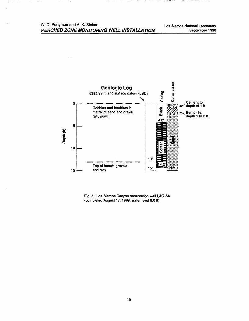
Los Alamos Canyon observation well LA0-6A was completed through the alluvium into the top of a basalt flow (Fig. 5). The well contained water when
5

W. D. Purtymun and A. K. Stoker
PERCHED ZONE MONrrORING WELL INSTALLATION Los Alamos National laboratory
September 1990
completed but went dry during the summer as the aquifer retreated up the _canyon.
C. Sandia Canyon
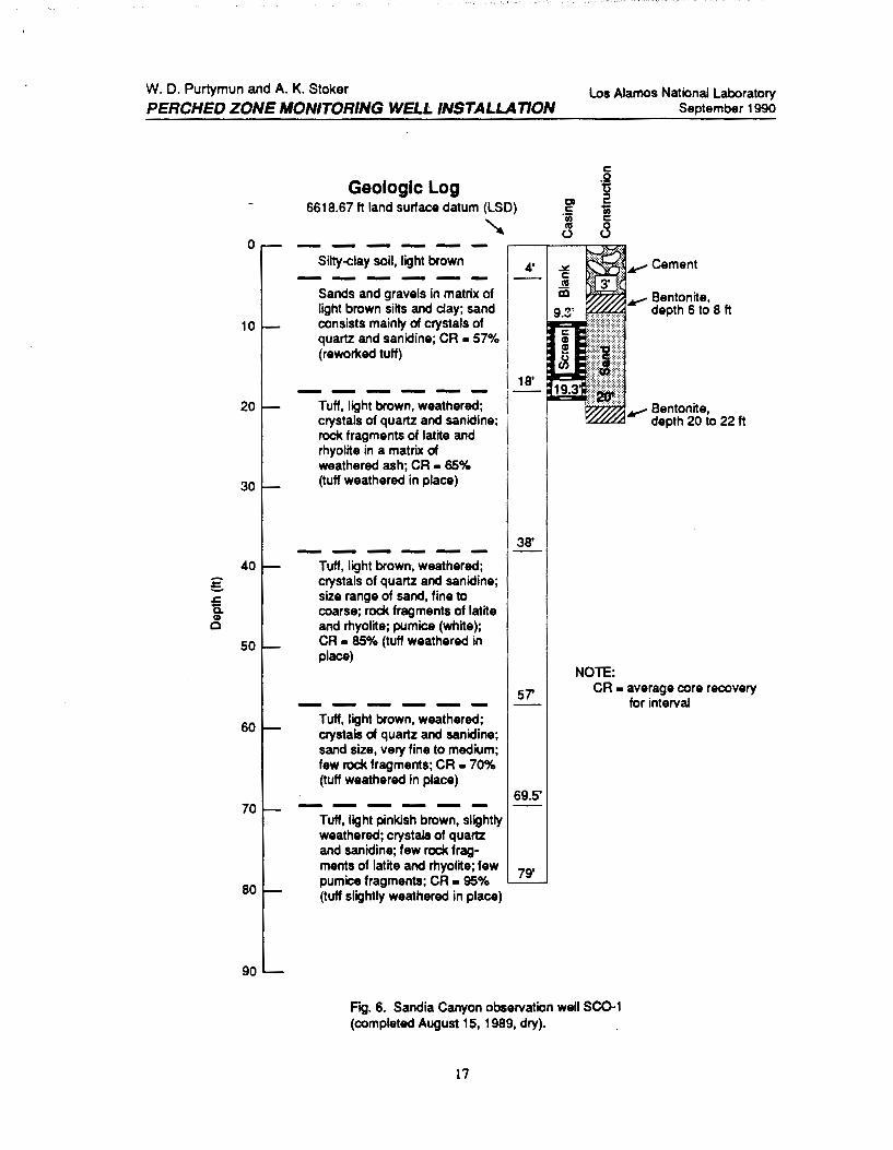
Sandia Canyon observation well SCO-t was completed in alluvium underlain by a weathered tuff. The alluvium was dry (Fig. 6).
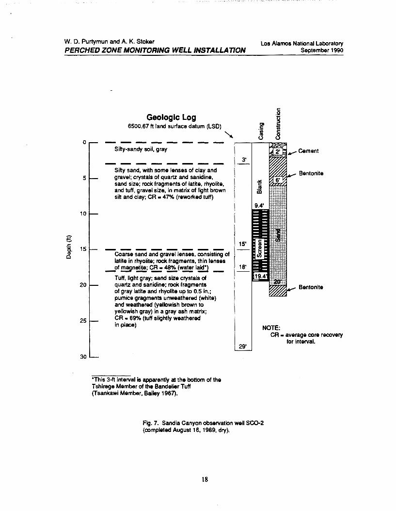
Sandia Canyon observation well SC0-2 was completed in alluvium underlain by a weathered tuff. The alluvium was dry (Fig. 7).
Although the alluvium was dry at both locations. the holes were finished as wells because there is a possibility an increase in run-off could saturate pan of the alluvium.
D. Mortandad Canyon
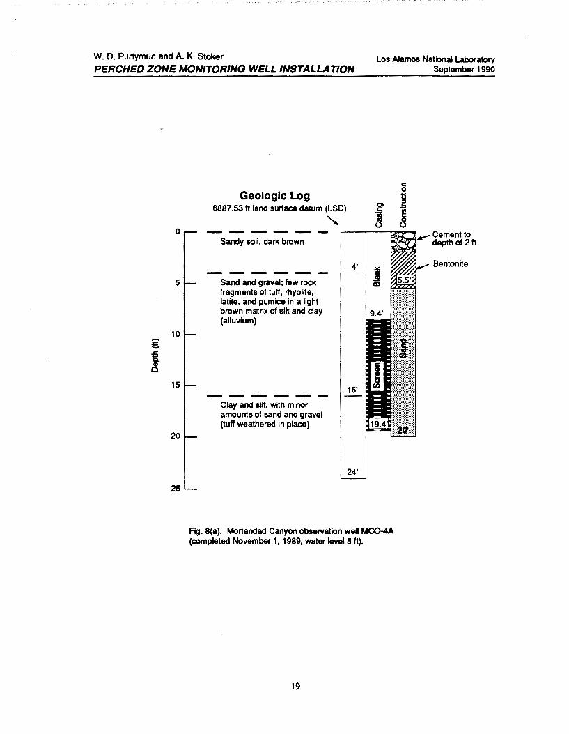
Mortandad Canyon observation well MC0-4A was completed in the alluvium and contained water when completed [Fig. 8(a)]. The well went dry during the summer, and a second well (MC0-48) was constructed through the alluvium and into the top of the weathered tuff [Fig. 8(b)]. Water was encountered in the alluvium perched above the tuff. The second well was constructed with a 20-ft screen section to allow sampling even with the wide range of water-level fluctuation in the canyon.
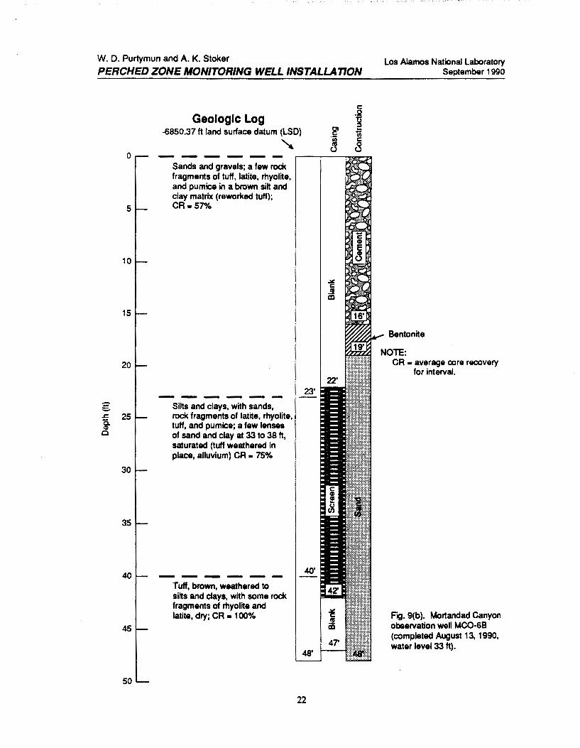
Mortandad Canyon observation well MC0-6A was completed in the alluvium and contained water when completed [Fig. 9(a)]. The well went dry during the summer, and a second well (MC0-68) was drilled through the alluvium into the top of the weathered tuff [Fig. 9(b)J. Water was encountered in the alluvium above the tuff. The well was equipped with a 20-ft screen section.
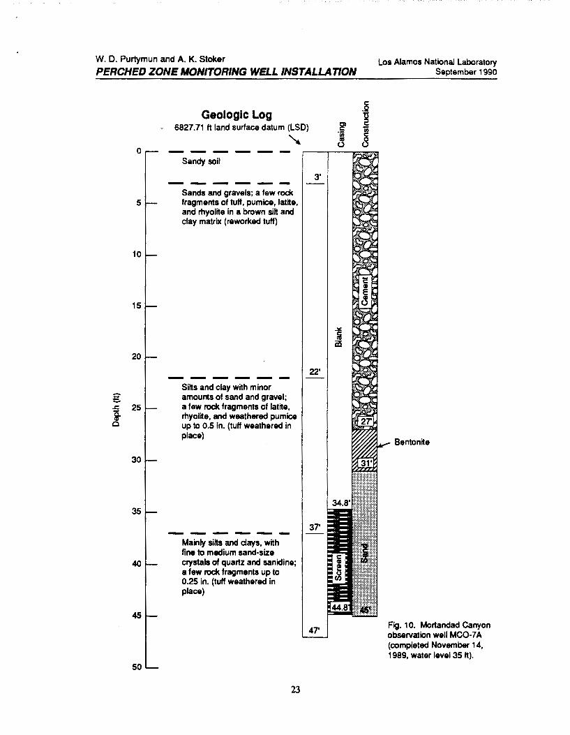
Mortandad Canyon observation well MC0-7 A was completed in the alluvium (Fig. 1 0). The well encountered water in the alluvium.
E. Potrillo Canyon
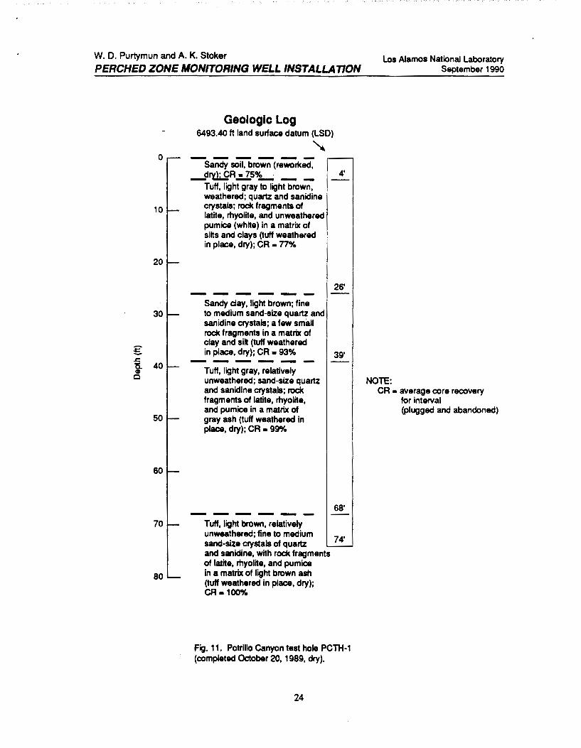
Potrillo Canyon test hole PCTH-1 was cored to a depth of74 ft (Fig. 11). The hole penetrated a thin soil zone of reworked material and a thiclc section of weathered to unweathered tuff. The entire section was dry and indicated no presence of past water. The hole was abandoned and plugged with a cementbentonite slurry.
6
W. D. Purtymun and A. K. Stoker
PERCHED ZONE MONITORING WELL INSTALLATION
F. Fence Canyon
Los Alamos National Laboratory September 1990
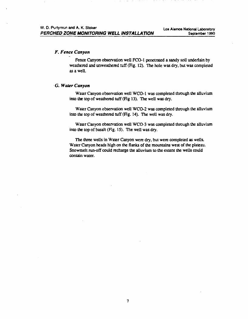
Fence Canyon observation well FC0-1 penetrated a sandy soil underlain by weathered and unweathered tuff (Fig. 12). The hole was dry, but was completed as a well.
G. Water Canyon
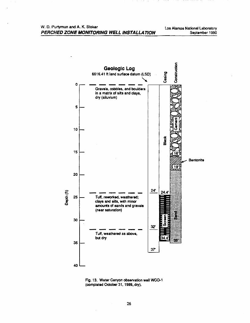
Water Canyon observation well WC0-1 was completed through the alluvium into the top of weathered tuff (Fig 13). The well was dry.
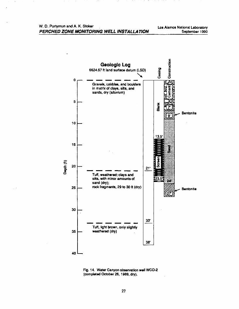
Water Canyon observation well WC0-2 was completed through the alluvium into the top of weathered tuff (Fig. 14). The well was dry.
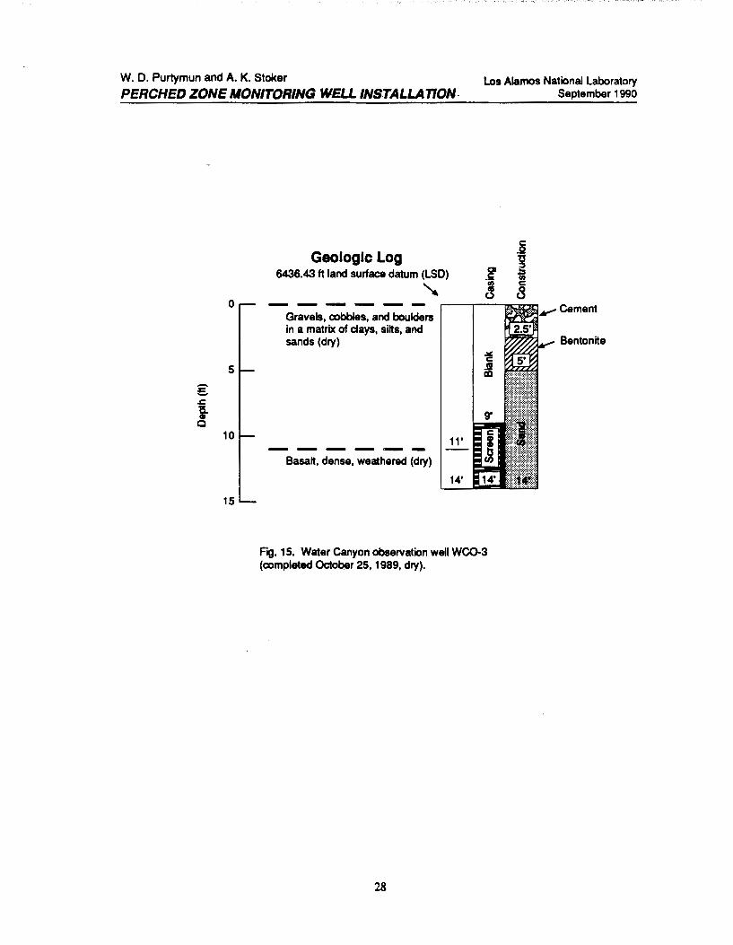
Water Canyon observation well WC0-3 was completed through the alluvium into the top of basalt (Fig. 15). The well was dry.
The three wells in Water Canyon were dry, but were completed as wells. Water Canyon heads high on the flanks of the mountains west of the plateau. Snowmelt run-off could recharge the alluvium to the extent the wells could contain water.
7
W. D. Purtymun and A. K. Stoker PERCHED ZONE MONrrORING WELL INSTALLATION'
Los Alamos National laboratory September 1990
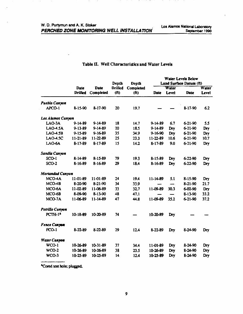
Table II. Well Characteristics and Water Levels
Water Levels Below Depth Depth Land Surface Datum (ft)
Date Date Drilled Completed Water Water Drilled Completed (ft) (ft) Date Level Date Level
Plleblo Ctmyo11 APC0-1 8-15-90 8-17-90 20 19.7 8-17-90 6.2
Los Alamos CaiiJOII LA0-3A 9-14-89 9-14-89 18 14.7 9-14-89 6.1 6-21-90 5.5 LA0-4.5A 9-13-89 9-14-89 20 18.5 9-14-89 Dry 6-21-90 Dry LA0-4.5B 9-15-89 9-16-89 35 34.9 9-16-90 Dry 6-21-90 Dry LA0-4.5C 11-21-89 11-22-89 25 23.3 11-22-89 10.6 6-21-90 10.7 LA0-6A 8-17-89 8-17-89 15 14.2 8-17-89 9.0 6-21-90 Dry
Salld/4 Ctmyo11 SC0-1 8-14-89 8-15-89 79 19.3 8-15-89 Dry 6-22-90 Dry SC0-2 8-16-89 8-16-89 29 18.4 8-16-89 Dry 6-22-90 Dry
Mortandlul Ca11yo11 MC0-4A 11-01-89 11-01-89 24 19.4 11-14-89 5.1 8-15-90 Dry MC0-4B 8-2(}.90 8-21-90 34 33.9 8-21-90 21.7 MC0-6A 11-02-89 11-06-89 33 32.7 11-09-89 30.3 6-02-90 Dry MC0-6B 8-09-90 8-13-90 48 47.1 8-13-90 33.2 MC0-7A 11-06-89 11-14-89 47 44.8 11-09-89 35.2 6-21-90 37.2
Potrillo Ca11yo11 PCTH-1• 10-18-89 10-20-89 74 10-20-89 Dry
FeMe ca,.. FC0-1 8-22-89 8-22-89 29 12.4 8-22-89 Dry 8-24-90 Dry
Water CIUI1flll WC0-1 10-26-89 10-31-89 37 34.4 11-01-89 Dry 8-24-90 Dry WC0-2 10-26-89 10-26-89 38 23.5 10-26-89 Dry 8-24-90 Dry WC0-3 10-25-89 10-25-89 14 12.4 10-25-89 Dry 8-24-90 Dry
&cored test hole; plugged.
9
W. D. Purtymun and A. K. Stoker PERCHED ZONE JIONrrORIIIG WELL INSTALLA nON
Los Alamos National Laboratory September 1990
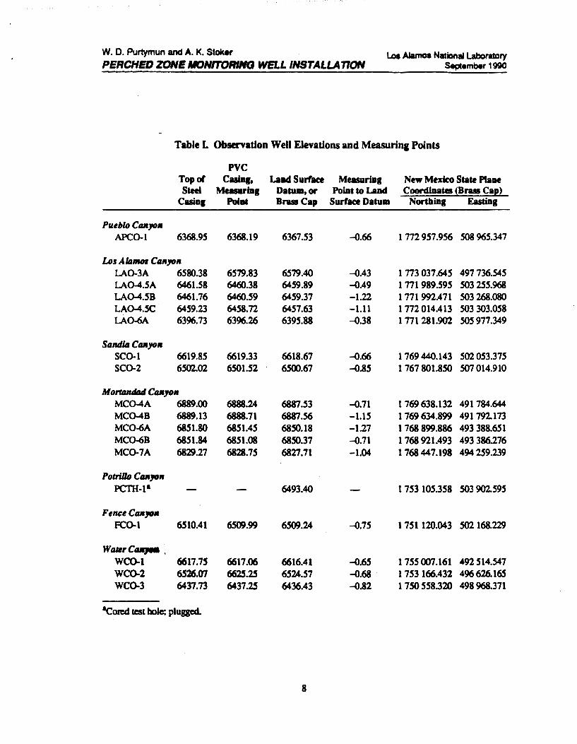
Table L Observation Well Elevations and Measuring Points
PVC Topol Cuiq, LaDd Surface Measurin1 New Mexico State Plaae Steel Measurin1 Datulll,or Poiat to Laad Coordiaates (Brass Caf!)
Casia1 Poi at Brass Cap Surface Datum NorthiDI Eastinl
Pueblo C1111yo11 APC0-1 6368.95 6368.19 6367.53 -o.66 1 772 957.956 508 965.347
Los AlamoJ Canyo• LA0-3A 6580.38 6579.83 6579.40 -o.43 1 773 037.645 497 736.545 LA0-4.5A 6461.58 6460.38 6459.89 -o.49 1 771 989.595 503 255.968 LA0-4.58 6461.76 6460.59 6459.37 -1.22 1 771 992.471 503 268.080 LA0-4.5C 6459.23 6458.72 6457.63 -1.11 1 772 014.413 503 303.058 LA0-6A 6396.73 6396.26 6395.88 -o.38 1 771 281.902 505977.349
Salldill C1111yo11 SC0-1 6619.85 6619.33 6618.67 -o.66 1 769 440.143 502053.375 SC0-2 6502.02 6501.52 6500.67 -o.85 1 767 801.850 507014.910
Mot1ll1Ulllll Ca•10• MC0-4A 6889.00 6888.24 6881.53 -o.71 1 769 638.132 491784.644 MC0-4B 6889.13 6888.71 6887.56 -1.15 1 769 634.899 491 792.173 M~A 6851.80 6851.45 6850.18 -1.27 1 768 899.886 493 388.651 MC0-6B 6851.84 6851.08 6850.37 -o.71 1 768 921.493 493 386.276 MC0-7A 6829.27 6828.75 6827.71 -1.04 1 768 447.198 494 259.239
Potrlllo C11111011 PCTH-1• 6493.40 1 753 105.358 503 902.595
Fenee C11111011 FC0-1 6510.41 6509.99 6509.24 -o.75 1 751 120.043 S02 168.229
Wt~Mrc...,_.
WC0-1 6617.75 6617.06 6616.41 -o.65 1 155 007.161 492514.547 WC0-2 6526.01 6625.25 6524.57 -o.68 1 753 166.432 496626.165 WC0-3 6437.73 6437.25 6436.43 -o.82 1 750 558.320 498968.371
il(:oted test hole; plugged.
8
W. D. Purtymun and A. K. Stoker
PERCHED ZONE MONITORING WELL INSTALLATION
.5 c:o ii
Cap ~ 3-in.-o.d. steel pipe with--.,~ ~ plate welded on top ------....,
T .5
\1 1-in. steel plate run through holes in 13-in. cap and 8.625-in.-o.d. casing (hole in bar for lock)
Steel casing set in cement of wellhead
los Alamos National laboratory September 1990
Observation well (2 in. i.d.)
Hinge
I
FIQ. 1. Two types of wellhead security locks used on canyon observation wells.
10

W. D. Purtymun and A. K. Stoker
PERCHED ZONE MONITORING WELL INSTALLATION
Geologic Log 6367.53 ft land Surface datum (LSD)
' 0 -----------
5
g ..c: li. 10 CD
0
Gravels, cobbles, and boulders of rhyolite, latite, and quartz latite in a matrix of clay, silt, and sand (alluvium)
Silstone and claystone, with lenses of sand and gravel, dry; part of
15 Puye Conglomerate over
20
lying basalt that outcrops to east
Los Alamos National Laboratory September 1990
C) c:
"(ij Ill (.)
c: 0 ·u 2 iii c:
8
"" Cement
Fig. 2. Pueblo Canyon observation well APC0-1 (completed August 17, 1990, water level 6 tt).
11

W. D. Purtymun and A. K. Stoker Los Alamos National Laboratory September 1 990 PERCHED ZONE MONITORING WELL INSTALLA T/ON
0
5
~ 10 Gl
Q
15
20
Geologic Log 6579.40 ft land surface datum (LSD)
~ ------Cobbles and boulders in matrix of sand and gravels (alluvium)
,.------r----.::7-::::JI¥"" Cement to depth of 2ft
Mainly silt and clays, with thin lenses of sands and gravels (tuff, weathered in place)
14'
Fig. 3. Los Alamos Canyon observation well LA0-3A (completed September 14, 1989, water level 7ft).
12
¥""Bentonite, . . depth 2 to 3 ft

W. D. Purtymun and A. K. Stoker
PERCHED ZONE. MONITORING WELL INSTALLATION
Geologic Log 6459.89 ft land surface datum (LSD)
~ 0 ------
5
....... £ .c g. 10 c
15
20
Cobbles and boulders in matrix of sand and gravels, dry (alluvium)
Siltstone and claystone with lenses of sand and gravel, dry; part of Puye Conglomerate, associated with basalts that outcrop to east; dry
Los Alamos National Laboratory September 1 990
C) c: ·u; liS 0
c: 0
~ u; c:
8
Bentonite
FIQ. 4(a). Los Alamos Canyon observation well LA0-4.5A (completed September 14, 1989, dry).
13
W. D. Purtymun and A. K. Stoker
PERCHED ZONE MONITORING WELL INSTALLATION
g ..r:. a Gl 0
Geologic Log 6459.37 ft land surface datum (LSD)
~ 0 ------
5
10
15
20
25
30
35
Cobbles and boulders in matrix of sand and gravel, dry (alluvium)
------Siltstone and claystone, with lenses of sand and gravel, saturated; lenses of sand sealed out of well above 25 ft, lower section dry; part of Puye Conglomerate and associated basalt to east
Los Alamos National Laboratory September 1 990
c: .Q ts ::I ... Ui c: 8
..- Bentonite
Fig. 4(b). los Alamos Canyon observation well LA0-4.58 (completed September 16, 1989, dry)
14
W. D. Purtymun and A. K. Stoker
PERCHED ZONE MONITORING WELL INSTALLATION
g .s:; a CD
Q
Geologic Log 6457.63 ft land surface datum (LSD)
~ 0 ------
20
25
Cobbles and boulders in matrix of sands and gravels, dry (alluvium)
Siltstone and claystone, with lenses of sand and gravel; part of Puye Conglomerate and associated basalts to east
Los Alamos National Laboratory September 1990
c .Q g .... iii c
8
Fig. 4(c). Los Alamos Canyon observation well LA0-4.50 (completed November 22, 1989, water level 11 ft).
15
W. D. Purtymun and A. K. Stoker
PERCHED ZONE MONITORING WELL /NSTALLA TION
Geologic Log 6395.88 ft land surface datum (LSD)
~ 0 ------
Cobbles and boulders in matrix of sand and gravel (alluvium)
5 g .z:. a Q)
Q
10
-----Top of basalt, gravels
15 and clay
C) c ·u; 111 0
Los Alamos National Laboratory September 1990
c .2 ts ::::J .... ;; c
8 Cement to M""" depth of 1 ft
......._Bentonite, depth 1 to 2 ft
Fig. 5. Los Alamos Canyon observation well LA0-6A (completed August 17, 1989, water level 9.0 ft).
16
W. D. Purtymun and A. K. Stoker
PERCHED ZONE MONITORING WELL INSTALLATION
Geologic Log 6618.67 ft land surface datum (LSD)
~ 0 -----
Silty-clay soil, light brown 4' ------Sands and gravels in matrix of light brown silts and clay; sand
10 consists mainly of crystals of quartz and sanidine; CR • 57% (reworked tuff)
18' ------20 Tuff, light brown, weathered;
crystals of quartz and sanidine; rock fragments of latite and rhyolite in a matrix of weathered ash; CR • 65%
30 (tuff weathered in place)
38' ------40 Tuff, light brown, weathered;
g crystals of quartz and sanidine; .t::. size range of sand, fine to a coarse; rock fragments of latite Q)
0 and rhyolite; pumice (white);
50 CR • 85% (tuff weathered in place)
57 --- ---60
Tuff, light brown, weathered; crystals of quartz and sanidine; sand size, very fine to medium; few rock fragments; CR • 70% (tuff weathered in place)
69.5' 70 ------
Tuff, light pinkish brown, slightly weathered; crystals of quartz and sanidine; few rock trag-ments of latite and rhyolite; few
79' 80
pumice fragments; CR • 95% (tuff slightly weathered in place)
90
C) c:
"iii I"CI
(.)
~ c: ~ IX)
Los Alamos National Laboratory September 1990
c: .2 u ;::) .... iii c: 8
Cement
Bentonite, depth 6 to 8 ft
_,.., Bentonite, depth 20 to 22 ft
NOTE: CR • average core recovery
for interval
Fig. 6. Sandia Canyon observation well SC0-1 (completed August 15, 1989, dry).
17
W. D. Purtymun and A. K. Stoker
PERCHED ZONE MONITORING WELL INSTALLATION
0
5
10
g ..c a 15 al
0
20
25
30
Geologic Log 6500.67 ft land surface datum (LSD)
~ -------Silty-sandy soil, gray
Silty sand, with some lenses of clay and gravel; crystals of quartz and sanidine, sand size; rock fragments of latite, rhyolite, and tuff, gravel size, in matrix of light brown silt and clay; CR • 47% (reworked tuff)
--------Coarse sand and gravel lenses, consisting of latite in rhyolite; rock fragments, thin lenses
3'
15'
_of magn!!J!!; ~ 4!!.(W.!!!,r laid*) 18'
Tuff, light gray; sand size crystals of quartz and sanidine; rock fragments of gray latite and rhyolite up to 0.5 in.; pumice gragments unweathered (white) and weathered (yellowish brown to yellowish gray) in a gray ash matrix; CR • 69% (tuff slightly weathered in place)
*This 3-ft interval is apparently at the bottom of the Tshirege Member of the Bandelier Tuff (Tsankawi Member, Bailey 1967).
29'
Los Alamos National Laboratory September 1990
c: .Q
~ c: 8
NOTE:
Cement
Bentonite
Bentonite
CR • average core recovery for interval.
FIQ. 7. Sandia Canyon observation well SC0-2 (completed August 16, 1989, dry).
18
W. D. Purtymun and A. K. Stoker
PERCHED ZONE MONITORING WELL INSTALLATION
Geologic Log 6887.53 ft land surface datum (LSD)
~ 0 -----
Sandy soil, dark brown
------5 Sand and gravel; few rock
fragments of tuff, rhyolite, latite, and pumice in a light brown matrix of silt and clay (alluvium)
10 .-.. :E. .c a ~
0
15 ------Clay and silt, with minor amounts of sand and gravel (tuff weathered in place)
20
25
Los Alamos National Laboratory September 1990
c _g t3 ;:, a ...
.s u; II) c ca 8 (.)
Cement to depth of 2 f1
Bentonite
Fig. 8(a). Mortandad Canyon observation well MC0-4A (completed November 1, 1989, water level 5 f1).
19

W. D. Purtymun and A. K. Stoker
PERCHED ZONE MONITORING WELL INSTALLATION
-e .r: a Q)
Cl
Geologic Log 6887.56 ft land surface datum (LSD)
'
c .2 g .... u; c 8
0 -----
5
10
15
20
25
30
35
Sandy soil, dark brown CR-65%
Sand and gravel; a few rock fragments of tuff, rhyolite, latite, and pumice in a matrix of silts and clay (alluvium) CR·53%
------Silts, clay, and coarse sand, alternating; some rock fragments of rhyolite, latite, and pumice (tuff weathered in place); CR • 86%
- ---- -Tuff, dark brown, weathered to silts and clays CR • 96%
Fig. 8(b). Mortandad Canyon observation well MC0-48 (completed August 21, 1990, water level 22ft).
20
Los Alamos National Laboratory September 1990
Cement
NOTE: CR • average core recovery
for interval.

W. D. Purtymun and A. K. Stoker
PERCHED ZONE MONITORING WELL INSTALLA T/ON
€
Geologic Log 6850.18 ft land surface datum (LSD)
~ 0 ------
Sandy soil .
Sands and gravels; a few rock 5 fragments of tuff, pumice, latite,
and rhyolite, and pumice in a brown silt and clay matrix (reworked tuff)
10
15
..c 20 i 0
25
30
35
40
------Silts and clays with fine to coarse sand; rock fragments of rhyolite, latite, and pumice; sand-size fragments; quartz and sanidine crystals and crystal fragments (tuff weathered in place)
Los Alamos National Laboratory September 1990
Bentonite
Fig. 9(a). Mortandad Canyon observation well MC0-6A (completed November 6, 1989, water level 30 ft).
21
W. D. Purtymun and A. K. Stoker
PERCHED ZONE MONITORING WELL INSTALLATION
--:::..
Geologic Log -6850.37 ft land surface datum (LSD)
' 0 ------Sands and gravels; a few rock fragments of tuff, latite, rhyolite, and pumice in a brown silt and clay matrix (reworked tuff);
5 CR·57%
10
15
20
Silts and clays, with sands, .s::. 25 i
rock fragments of latite, rhyolite, tuff, and pumice; a few lenses of sand and clay at 33 to 38 ft, saturated (tuff weathered in place, alluvium) CR • 75%
Cl
30
35
40 ------
45
50
Tuff, brown, weathered to silts and clays, with some rock fragments of rhyolite and latite, dry; CR • 1 00%
22
los Alamos National laboratory September 1990
Bentonite
CR • average core recovery for interval.
FIQ. 9(b). Mortandad Canyon observation well MC0-68 (completed August 13, 1990, water level 33 ft).
W. D. Purtymun and A. K. Stoker
PERCHED ZONE MONITORING WELL INSTALLATION
........ £
Geologic Log 6827.71 ft land surface datum (LSD)
' 0 ------Sandy soil
Sands and gravels; a few rock 5 fragments of tuff, pumice, latite,
and rhyolite in a brown silt and clay matrix (reworked tuff)
10
15
20
Silts and clay with minor amounts of sand and gravel;
.&: 25 i
a few rock fragments of latite, rhyolite, and weathered pumice up to 0.5 in. (tuff weathered in place)
0
30
35
Mainly silts and clays, with fine to medium sand-size
40 crystals of quartz and sanidine; a few rock fragments up to 0.25 in. (tuff weathered in place)
45
50
23
3'
22'
Los Alamos National Laboratory September 1 990
Bentonite
Fig. 10. Mortandad Canyon observation well MCO-7 A (completed November 14, 1989, water level 35 ft).
W. D. Purtymun and A. K. Stoker
PERCHED ZONE MONITORING WELL INSTALLATION
0
10
20
30
g ..r:: l5.. 40 <D 0
50
60
70
80
Geologic Log 6493.40 ft land surface datum (LSD)
' -----Sandy soil, brown (reworked, _d~R~S'L_ __
Tuff, light gray to light brown, weathered; quartz and sanidine crystals; rock fragments of latite, rhyolite, and unweathered pumice (white) in a matrix of silts and clays (tuff weathered in place, dry); CR - 770fo
------Sandy clay, light brown; fine to medium sand-size quartz and sanidine crystals; a few small rock fragments in a matrix of clay and silt (tuff weathered in place, dry); CR • 930fo ------Tuff, light gray, relatively unweathered; sand-size quartz and sanidine crystals; rock fragments of latite, rhyolite, and pumice in a matrix of gray ash (tuff weathered In place, dry); CR • 99o/o
------Tuff, light brown, relatively unweathered; fine to medium sand-size crystals of quartz and sanidine, with rock fragments of latite, rhyolite, and pumice in a matrix of light brown ash (tuff weathered in place, dry); CR ·1000fo
4'
26'
39'
68'
74'
Fig. 11. Potrillo Canyon test hole PCTH-1 (completed October 20, 1989, dry).
24
Los Alamos National Laboratory September 1990
NOTE: CR • average core recovery
for interval (plugged and abandoned)

W. D. Purtymun and A. K. Stoker
PERCHED ZONE MONITORING WELL INSTALLATION
0
5
10
-£ .c: a 15 (II
0
20
25
30
Geologic Log 6509.24 ft land surface datum (LSD)
Sandy soil, light brown; CR • 64o/o
Tuff, light brown, weathered, to silts and clays with some sand and gravel (weathered in place, dry); CR • 49%
"
Tuff, light pink, some weathering; silt and clay with sand and gravel (weathered in place, dry); CR • 91 o/o
29'
Fig. 12. Fence Canyon observation well FC0-1 (completed August 22, 1989, dry).
25
Los Alamos National Laboratory September 1990
NOTE:
Blank
Cement to 1.5 ft
Bentonite, 1.5 to 2.5 ft
Bentonite
CR • average core recovery for interval
W. D. Purtymun and A. K. Stoker
PERCHED ZONE MONrrORING WELL INSTALLATION
5
10
15
g -g_ 25 Gl
0
30
35
40
Geologic Log 6616.41 ft land surface datum (LSD)
"' Gravels, cobbles, and boulders in a matrix of silts and clays, dry (alluvium)
------Tuff, reworked, weathered; clays and silts, with minor amounts of sands and gravels (near saturation)
Tuff, weathered as above, but dry
Fig. 13. Water Canyon observation well WC0-1 (completed October 31, 1989,. dry).
26
Los Alamos National Laboratory September 1990
Bentonite
W. D. Purtymun and A. K. Stoker .
PERCHED ZONE MONITORING WELL INSTALLA nON
-s.
Geologic Log 6624.57 ft land surface datum (LSD)
' 0 ------
5
10
15
Gravels, cobbles, and boulders in matrix of clays, silts, and sands, dry (alluvium)
.s:: 20 ~ 21' c
25
30
Tuff, weathered; clays and silts, with minor amounts of sand (dry); rock fragments, 29 to 30 ft (dry)
------Tuff, light brown, only slightly
33'
35 weathered (dry)
40
38'
Fig. 14. Water Canyon observation well WC0-2 (completed October 26, 1989, dry).
27
Los Alamos National Laboratory September 1990
c .g g ... in c 8
Bentonite
Bentonite
W. D. Purtymun and A. K. Stoker
PERCHED ZONE MONITORING WELL INSTALLAnON.
Geologic Log 6436.43 ft land surface datum (LSD)
' 0 ------Gravels, cobbles, and boulders in a matrix of clays, sibs, and sands (dry)
5 ..-. s .&: a Gl c
10 11' ----~-
Basah, dense, weathered (dry)
14'
15
los Alamos National laboratory September 1990
c .g -g
-~ .. u;
Ill c ~ 8
Bentonite
F"~g. 15. Water Canyon observation well WC0-3 (completed October 25, 1989, dry).
28
LA- U R :90-4300
PERCHED ZONE MONITORING WELLS
ANALYTICAL RESULTS
ENVIRONMENTAL RESTORATION PROGRAM
December 19, 1990
PERCHED ZONE MONITORING WELLS ANALYTICAL RESULTS
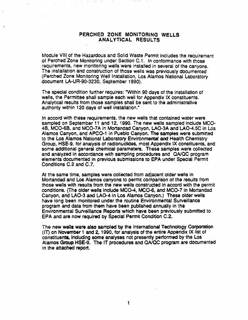
Module VIII_ of the Hazardous and Solid Waste Permit includes the requirement of Perched Zone Monitoring under Section C.1. In conformance with those requirements, new monitoring wells were installed in several of the canyons. The installation and construction of those wells was previously documented (Perched Zone Monitoring Well Installation, Los Alamos National Laboratory document LA-UA-90-3230, September 1990).
The special condition further requires: "Within 90 days of the installation of wells, the Permittee shall sample each well for Appendix IX constituents. Analytical results from those samples shall be sent to the administrative authority within 120 days of well installation."
In accord with these requirements, the new wells that contained water were sampled on September 11 and 12, 1990. The new wells sampled include MC0-48, MC0-68, and MC0-7A in Mortandad Canyon, LA0-3A and LA0-4.5C in Los Alamos Canyon, and APC0-1 in Pueblo Canyon. The samples were submitted to the Los Alamos National Laboratory Environmental and Health Chemistry Group, HSE-9, for analysis of radionucfides, most Appendix IX constituents, and some additional general chemical parameters. These samples were collected and analyzed in accordance wit~ sampling procedures and QA/QC program elements documented in previous submissions to EPA under Special Permit Conditions C.2 and C.7.
At the same time, samples were collected from adjacent older wells in Mortandad and Los Alamos canyons to permit comparison of the results from those wells with results from the new wells constructed in accord with the permit conditions. (The older wells include MC0-4, MC0-6, and MCO· 7 in Mortandad Canyon, and LA0-3 and LA0-4 in Los Alamos Canyon.) These older wells have long been monitored under the routine Environmental Surveillance program and data from them have been published annually in the Environmental Surveillance Reports which have been previously submitted to EPA and are now required by Special Permit Condition C.2.
The new wells were also sampled b.y the International Technology Corporation (IT) on November 1 and 2, 1990, for analysis of the entire Appendix IX list of constituents. including some analyses not presently performed by the Los Alamos Group HSE-9. The IT procedures and QA/QC program are documented in the attached report.
1

The results of the laboratory analyses are summarized in four attached tables:
Table I summarizes Radiochemical Analyses for Gross Gamma, Gross Alph-a, 241 Am, Total U, 3·H, 137 Cs, 238Pu, and 239•240Pu. All of the constituents were present in locations and amounts expected from the results of the long term monitoring program.
Table II summarizes the Appendix IX Inorganic Constituents. Most of the metals were found in concentrations above detection limits in some or all of the samples, and in general, fit expectations of occurrence based on results of the long term monitoring program. Barium and lead levels were higher than previously observed. Sulfides were found in all the new wells at levels from 1 to 2.8 milligrams/L. Results from the two laboratories were comparable considering possible variation because of approximately seven weeks difference in sampling dates.
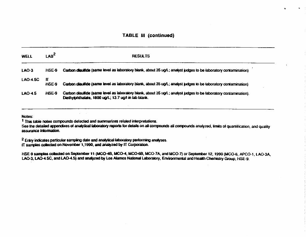
Table Ill summarizes the Appendix IX Organ;c Compounds Detected. The only Appendix IX organics detected that could not be attributed to minor analytical laboratory contamination included diethylphthalate (1800 micrograms/L) in the sample from one of the old wells (MC0-4.5) and the possible presence of N-nitrosomorpholine (3 micrograms/liter) in two of the new wells (MC0-48 and MC0-68) but at levels less than one-third of the reporting limit (10 micrograms/L) for the analytical method.
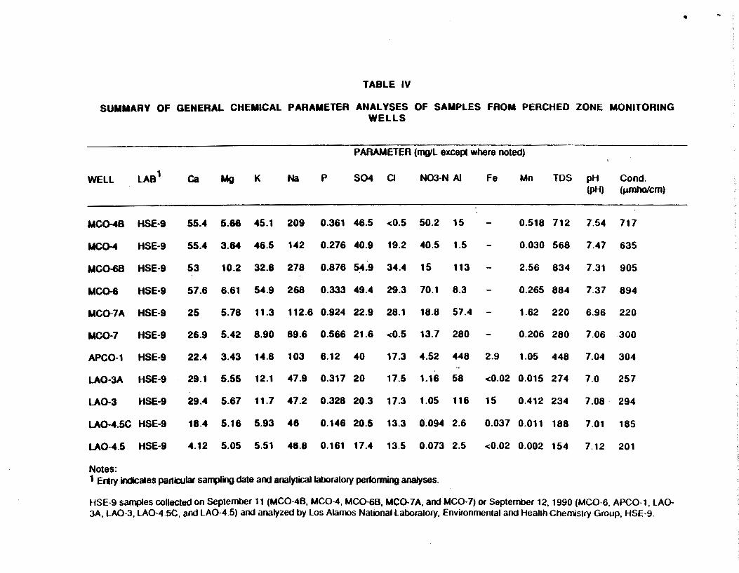
Table IV summarizes the general chemical parameters analyzed. These results indicate generally good comparability between the paired old and new wells.
All of the detailed analytical laboratory documentation is included as appendixes. The first appendix contains Los Alamos National Laboratory Environmental and Health Chemistry Group (HSE-9) documentation. The documentation is grouped with all radiochemical resuJts first, aJI organic results second, and all inorganic results third. The second appendix contains the report of results obtained for Los Alamos by International Technology Corporation.
2

TABLE I
SUMMARY OF RADIOCHEMICAL ANALYSES OF SAMPLES FROM PERCHED ZONE MONITORING WELLS
PARAMETER (pCill except where noted, +1- value is analytical standard deviation)
Gross Gross Gross Total u WELL LAB
1 3H 238pu 239,240pu 137cs 241Am Alpha Beta ~ (mg/L) (cm/L)
MC0-48 HSE-9 67000±7000 0.0529±0.0213 0.112±0.027 28±69 1.47±0.10 9±3 120±10 110±80 6.4±0.1
MC0-4 HSE-9 43000±4000 0.371±0.042 1.42±0.92 101±70 4.14±0.19 8±3 160±20 80±80 1.5±0.1
MC0-68 HSE-9 130000±10000 0.0187±0.0148 0.0327±0.0169 163±73 2.27±0.13 34±8 59±6 10±80 18.1±0.4
MC0-6 HSE-9 100000±10000 1.12±0.01 3.18±0.20 90±71 2.52±0.13 10±3 100±10 180±80 5.9±0.1
MC0-7A HSE-9 21000±2000 0.0172±0.0106 0.0344±0.0137 20±70 0.375±0.042 7±2 18±2 20±80 6.5±0.2
MC0-7 HSE-9 13000±1000 0.0178±0.0154 0.444±0.0155 87±70 0.216±0.034 3±1 12±1 210±80 1.4±0.1
APC0-1 HSE-9 0±300 0.0038±0.0085 0.152±0.026 46±71 0.0584±0.0178 23±6 18±2 80±80 1.7±0.2
LA0-3A HSE-9 1100±300 0.0047±0.0081 0.0094±0.0094 0±83 0.0389±0.0168 5±2 130±10 10±80 0.1±0.1
LA0-3 HSE-9 1300±300 0.0089±0.0089 0.0045±0.0077 11±63 0 .0635±0. 0203 5±2 130±10 20±80 6.6±0.7
LA0-4.5C HSE-9 700±300 0.039±0.0184 0.0742±0.0197 83±70 0.098±0.216 4±1 9±1 120±80 0.3±0.1
LA0-4.5 HSE-9 700±300 0.0084±0.0103 0.0126±0.0094 2±64 0.171±0.0306 2.4±0.9 7.5±0.9 280±80 0.1±0.1
Notes: 1 Ertry indicates particular sa~ling date and analytical laboratory performing analyses.
HSE-9 samples collected on Septerrt>er 11 (MC0-48, MC0-4, MC0-68, MC0-7A, and MC0-7) or September 12, 1990 (MC0-6, APC0-1, LA0-3A, LA0-3, LA0-4.5C, and LA0-4 5) and analyzed by Los Alamos National Laboratory, Environmental and Health Chemistry Group, HSE-9.

TABLE II
SUMMARY OF APPENDIX IX INORGANIC ANALYSES ON SAMPLES FROM PERCHED ZONE MONITORING WELLS
PARAMETER (microgramsJL)
WELL LAB1 Sb As Ba Be Cd Cr Co Cu Pb Hg Ni Se Ag Tl Sn v Zn CN Sulfides
(mg/L) (mg/L)
MCQ-48 rr <30 <40 190 <1 <5 <10 <20 10 <30 <1 <20 <60 <5 <40 <20 <10 81 0.01 2.0 HSE-9 0.5 15.1 337 2.1 0.9 17.3 16.5 42.3 <0.2 10.9 2.5 0.3 0.4 171 72 0.041
MC0-4 HSE-9 0.7 19.1 . 128 <0.1 0.9 15.9 17 2.8 <0.2 14.8 2.4 0.2 0.2 215 20 0.036
MCQ-68 rr <30 <40 690 4 <5 30 <20 30 70 <1 <20 <60 <5 <40 <20 30 150 <0.01 1.0 HSE-9 <0.5 12.7 1670 8.3 0.7 22.5 17 163 <0.2 17.3 2.2 1.3 2.1 155 149 0.046
MC0-6 HSE-9 <0.5 17.7 231 0.4 0.6 19.8 12.3 16.2 <0.2 16.3 2.6 <0.2 0.2 185 43 0.046
MCC>-7A rr <30 <40 420 3 <5 20 <20 30 50 <1 30 <60 <5 <40 <20 40 100 <0.01 1.6 HSE-9 <0.5 15.8 820 ~.7 0.7 28 21.2 94 <0.2 20.3 1 0.4 0.8 147 107 0.026
MCQ-7 HSE-9 <0.5 15.6 254 0.9 <0.5 15.8 49.7 16.8 <0.2 10.3 1 0.6 0.2 126 74 0.026
APC0-1 rr <30 <40 970 4 <5 30 40 120 80 <1 50 <60 <5 <40 <20 70 200 <0.01 1.6 HSE-9 0.5 3.5 301 2.1 1.1 29.5 33 10.6 <0.2 37 1. 1.0 0.5 91 123 0.26
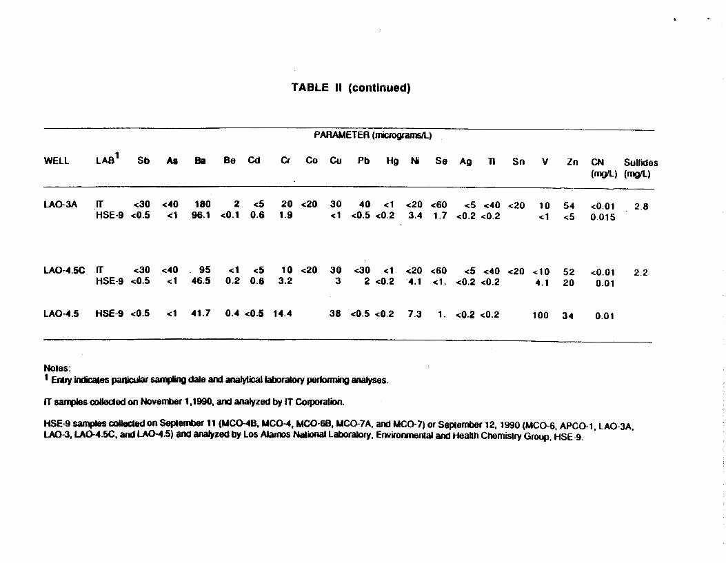
TABLE II (continued)
PARAMETER (micrograrnsll)
WEll lAB1
Sb As Ba Be Cd Cr Co Cu Pb Hg Ni Se Ag 11 Sn v Zn CN SuUides (mgll) (mgll)
LA0-3A rr <30 <40 180 2 <5 20 <20 30 40 <1 <20 <60 <5 <40 <20 10 54 <0.01 2.8 HSE-9 <0.5 <1 96.1 <0.1 0.6 1.9 <1 <0.5 <0.2 3.4 1.7 <0.2 <0.2 <1 <5 0.015
lA0-4.5C rr <30 <40 95 <1 <5 10 <20 30 <30 <1 <20 <60 <5 <40 <20 <10 52 <0.01 2.2 HSE-9 <0.5 <1 46.5 0.2 0.8 3.2 3 2 <0.2 4.1 <1. <0.2 <0.2 4.1 20 0.01
LA0-4.5 HSE-9 <0.5 <1 41.7 0.4 <0.5 14.4 38 <0.5 <0.2 7.3 1. <0.2 <0.2 100 34 0.01
Notes: 1 Eruy indicales panicular &aqlling dale and analytical laboratory pertonning analyses.
IT &afll)les oollecled on Novenmer 1,1990, and analyzed by IT Colporation.
HSE-9 samples colleeled on Seplenmer 11 (MCC>-48, MC0-4, MC0-68, MC0-7 A, and MC0-7) or September 12, 1990 (MC0-6, APC0-1, lA0-3A, LA0-3, LAC>-4.5C, and LA0-4.5) and analyzed by los Alamos National laboratory, Envirorvnenlal and Heallh Chemistry Group, HSE-9.

------------------------------------------------------------------------------------------------------------------------------~r------·
TABLE Ill
SUMMARY OF APPENDIX IX ORGANIC ANALYSES (COMPOUNDS DETECTED) ON SAMPLES FROM PERCHED. ZONE MONITORING WELLS 1
WELL
MC0-48
MC0-4
MC0-68
LA82 RESULTS
rr N-Nirosomorpholine, estimated at 3 ugll, noted by laboratory as below reporting limit of10 ug/L for method. HSE-9
HSE-9 Diethyl phthalate, 18 ugll; also found in blank at 13.7 ugll, analyst judges to be from laboratory contamination.
rr N-Nilrosomorpholine, estimated at 2 ugll, noted by laboratory as below reporting limit of 10 ug/L for method HSE-9 Methylene chloride 6 ugll, analyst judges to be from sa~e preparation or storage.
MC0-6 HSE-9
MC0-7A
MC0-7
APC0-1
LA0-3A
rr
HSE-9
Organophosphorus pesticide sample fraction exceeded holding time one day, nothing detected; resampled on Nov. 30 for reanalysis
HSE-9 1,1,2-Trichloro-1,2,2-trifluoroethane 6 ugiL, analyst judges to be from sample preparation or storage.
rr HSE-9 Carbon disutfide (same level as laboratory blank, about 35 ug/L; analyst judges to be laboratory contamination)
rr HSE-9 Carbon disulfide (same level as laboratory blank, about 35 ug/L; analyst judges to be laboratory contamination)
WEll LAB2
-
LA0-3 HSE-9
LA0-4.5C rr HSE-9
LA0-4.5 HSE-9
Notes:
TABLE Ill (continued)
RESULTS
Calbon dill elide (same level as laboratory blank, about 35 ugll; analyst judges to be laboratory contamination)
Carbon di&ullide (same level as laboratory blank, about 35 ugll; analyst judges to be laboratory contamination)
Calbon disulide (same level as laboratory blank, about 35 aql; analyst judges to be laboratory conlamination). Dielhy~halale, 1800 ugll; 13.7 ugll in lab blank.
1 This table notes compounds detected and summarizes related interpretations. See the detailed appendixes ol analyticallaboraiOiy reporls for details on all COfl1JOUnds all coq>Ounds analyzed, limits of quantification, and quality assurance inlonnatlon.
2 E11ry indicates particular &af11lling date and analytical laboratory pertormng analyses. IT s~s colecled on November 1,1990, and analyzed by IT Corporation.
HSE-9 samples coleded on September 11 (MCCHB, MC0-4, MCQ-68, MC0-7A, and MC0-7) or September 12, 1990 (MC0-6, APC0-1, LA0-3A, LA0-3,l.AQ-.t.SC, and LA0-4.5) and analyzed by los Alamos NationallaboraiOry, Environmental and HeaJih Chemistry Group, HSE-9.
•
• ..
TABLE IV
SUMMARY OF GENERAL CHEMICAL PARAMETER ANALYSES OF SAMPLES FROM PERCHED ZONE MONITORING WELLS
PARAMETER (mgiL except where noted)
WELL LAB1 Ca Mg K Na p S04 CJ NOO-N AI Fe Mn TDS pH Cond. (pH) (~em)
MC0-48 HSE·9 55.4 5.66 45.1 209 0.361 46.5 <0.5 50.2 15 - 0.518 712 7.54 717
MC0-4 HSE-9 55.4 3.84 46.5 142 0.276 40.9 19.2 40.5 1.5 - 0.030 568 7.47 635
MC0-68 HSE-9 53 10.2 32.8 278 0.876 54.9 34.4 15 113 - 2.56 834 7.31 905
MCQ-6 HSE-9 57.6 6.61 54.9 268 0.333 49.4 29.3 70.1 8.3 - 0.265 884 7.37 894
MC0-7A HSE-9 25 5.78 11.3 112.6 0.924 22.9 28.1 18.8 57.4 - 1.62 220 6.96 220
MC0-7 HSE-9 26.9 5.42 8.90 89.6 0.566 21.6 <0.5 13.7 280 - 0.206 280 7.06 300
APC0-1 HSE-9 22.4 3.43 14.8 103 6.12 40 17.3 4.52 448 2.9 1.05 448 7.04 304 .,
LA0-3A HSE-9 29.1 5.55 12.1 47.9 0.317 20 17.5 1.16 58 <0.02 0.015 274 7.0 257
LA0-3 HSE-9 29.4 5.67 11.7 47.2 0.328 20.3 17.3 1.05 116 15 0.412 234 7.08. 294
LA0-4.5C HSE-9 18.4 5.16 5.93 48 0.146 20.5 13.3 0.094 2.6 0.037 0.011 188 7.01 185
LA0-4.5 HSE-9 4.12 5.05 5.51 48.8 0.161 17.4 13.5 0.073 2.5 <0.02 0.002 154 7.12 201
Notes: 1 ERry indicates particular saf11)1ing dale and analytical laboratory performing analyses.
HSE-9 samples collected on September 11 (MC0-48, MC0-4, MC0-68, MC0-7A, and MC0-7) or September 12, 1990 (MC0-6, APC0-1, LAO-3A, LA0·3, LA0-4.5C, and LA0·4.5) and analyzed by Los Alamos National Laboratory, Environmental and Heallh Chemistry Group, HSE-9.
Related Documents