DRAFT ENVIRONMENTAL IMPACT STATEMENT PepsiCo Research & Development Facility Expansion Project 350 Columbus Avenue and 100 East Stevens Avenue Valhalla, NY 10595 TOWN OF MOUNT PLEASANT WESTCHESTER COUNTY, NEW YORK Date: January 2017 VOLUME II

Welcome message from author
This document is posted to help you gain knowledge. Please leave a comment to let me know what you think about it! Share it to your friends and learn new things together.
Transcript
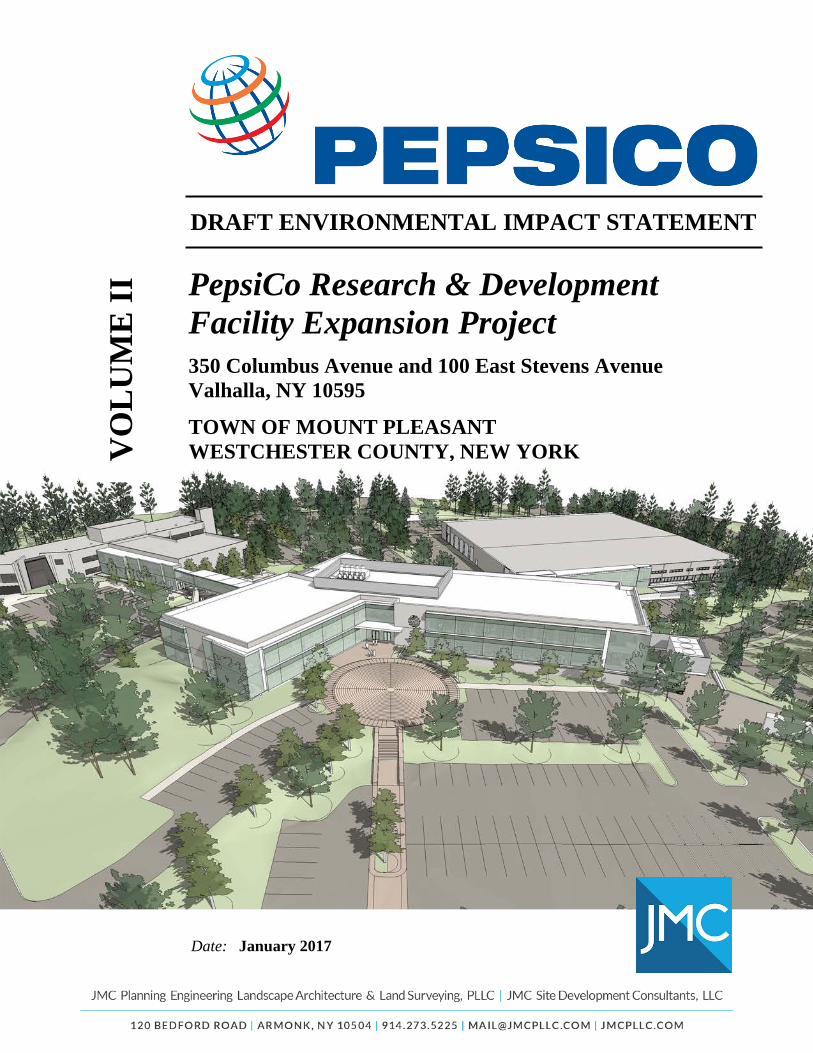
DRAFT ENVIRONMENTAL IMPACT STATEMENT
PepsiCo Research & Development Facility Expansion Project
350 Columbus Avenue and 100 East Stevens Avenue Valhalla, NY 10595
TOWN OF MOUNT PLEASANT WESTCHESTER COUNTY, NEW YORK
Date: January 2017
VO
LU
ME
II
APPENDICES A. All SEQRA documentation, including:
1. Environmental Assessment Form (EAF) Part 12. Positive Declaration3. Scoping Outline
B. CorrespondenceC. Geotechnical Data (Memoranda from Carlin Simpson & Associates, dated 06/23/2015
and 11/23/2015)D. Natural Resource Data
1. Wetland Delineation Report (Evans Associates Environmental Consultants, dated 5/24/2016)
2. National Wetland Inventory (NWI) Mapping (October 2016)3. NY Natural Heritage Program Documentation (Evans Associates
Environmental Consultants, dated 09/02/2016)4. Tree Survey Data
E. Stormwater Pollution Prevention Plan (JMC, dated 12/15/2016) [Refer to VOLUME II.E]F. Traffic Impact Study (Maser Consulting, dated 12/09/2016)G. Preliminary Assessment / Disturbance Memorandum (Historical Perspectives,
Inc., dated November 2016)H. NYSDEC Air Facility Registration Certificate I. Valhalla Fire Department Parcel Documentation
APPENDIX A
SEQR DOCUMENTATION
1. Full Environmental Assessment Form (Part 1)
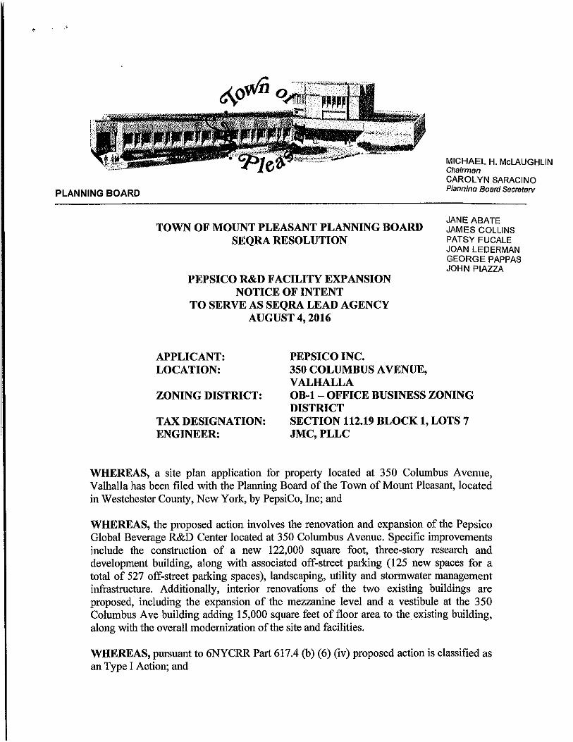
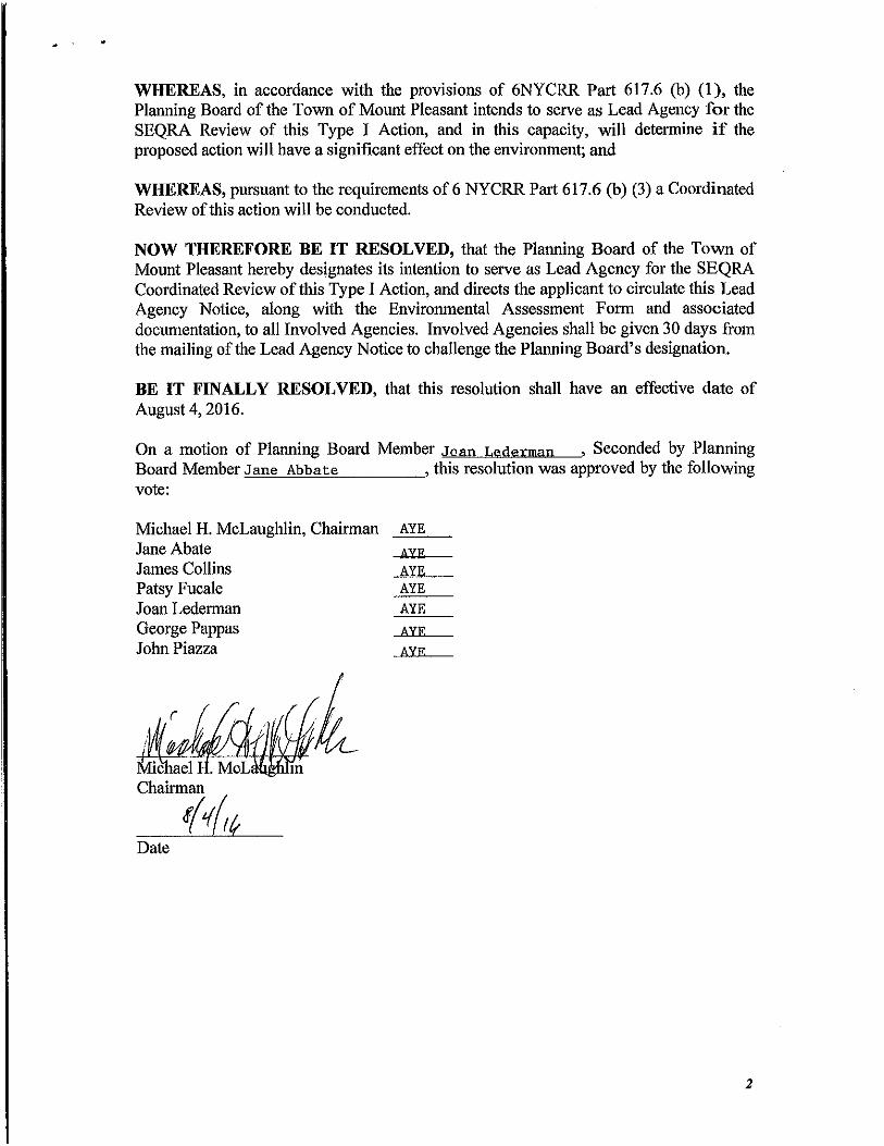
2. Notice of Intent to Serve as Lead Agency
3. Confirmation of Lead Agency, Positive Declaration
and Notice of Public Scoping Session
4. DEIS Scoping Outline
Page 1 of 13
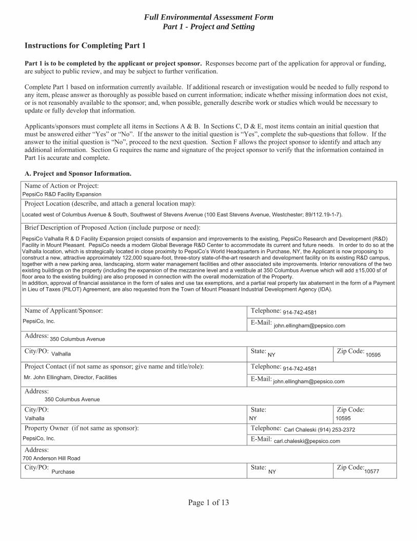
Full Environmental Assessment Form Part 1 - Project and Setting
Instructions for Completing Part 1
Part 1 is to be completed by the applicant or project sponsor. Responses become part of the application for approval or funding, are subject to public review, and may be subject to further verification.
Complete Part 1 based on information currently available. If additional research or investigation would be needed to fully respond to any item, please answer as thoroughly as possible based on current information; indicate whether missing information does not exist, or is not reasonably available to the sponsor; and, when possible, generally describe work or studies which would be necessary toupdate or fully develop that information.
Applicants/sponsors must complete all items in Sections A & B. In Sections C, D & E, most items contain an initial question thatmust be answered either “Yes” or “No”. If the answer to the initial question is “Yes”, complete the sub-questions that follow. If the answer to the initial question is “No”, proceed to the next question. Section F allows the project sponsor to identify and attach any additional information. Section G requires the name and signature of the project sponsor to verify that the information contained in Part 1is accurate and complete.
A. Project and Sponsor Information.
Name of Action or Project:
Project Location (describe, and attach a general location map):
Brief Description of Proposed Action (include purpose or need):
Name of Applicant/Sponsor: Telephone:
E-Mail:
Address:
City/PO: State: Zip Code:
Project Contact (if not same as sponsor; give name and title/role): Telephone:
E-Mail:
Address:
City/PO: State: Zip Code:
Property Owner (if not same as sponsor): Telephone: E-Mail:
Address:
City/PO: State: Zip Code:
PepsiCo R&D Facility Expansion
Located west of Columbus Avenue & South, Southwest of Stevens Avenue (100 East Stevens Avenue, Westchester; 89/112.19-1-7).
PepsiCo Valhalla R & D Facility Expansion project consists of expansion and improvements to the existing, PepsiCo Research and Development (R&D)Facility in Mount Pleasant. PepsiCo needs a modern Global Beverage R&D Center to accommodate its current and future needs. In order to do so at theValhalla location, which is strategically located in close proximity to PepsiCo’s World Headquarters in Purchase, NY, the Applicant is now proposing toconstruct a new, attractive approximately 122,000 square-foot, three-story state-of-the-art research and development facility on its existing R&D campus,together with a new parking area, landscaping, storm water management facilities and other associated site improvements. Interior renovations of the twoexisting buildings on the property (including the expansion of the mezzanine level and a vestibule at 350 Columbus Avenue which will add ±15,000 sf offloor area to the existing building) are also proposed in connection with the overall modernization of the Property.In addition, approval of financial assistance in the form of sales and use tax exemptions, and a partial real property tax abatement in the form of a Paymentin Lieu of Taxes (PILOT) Agreement, are also requested from the Town of Mount Pleasant Industrial Development Agency (IDA).
PepsiCo, Inc.914-742-4581
350 Columbus Avenue
Valhalla NY 10595
Mr. John Ellingham, Director, Facilities914-742-4581
350 Columbus Avenue
Valhalla NY 10595
PepsiCo, Inc.Carl Chaleski (914) 253-2372
700 Anderson Hill Road
Purchase NY 10577
Page 2 of 13
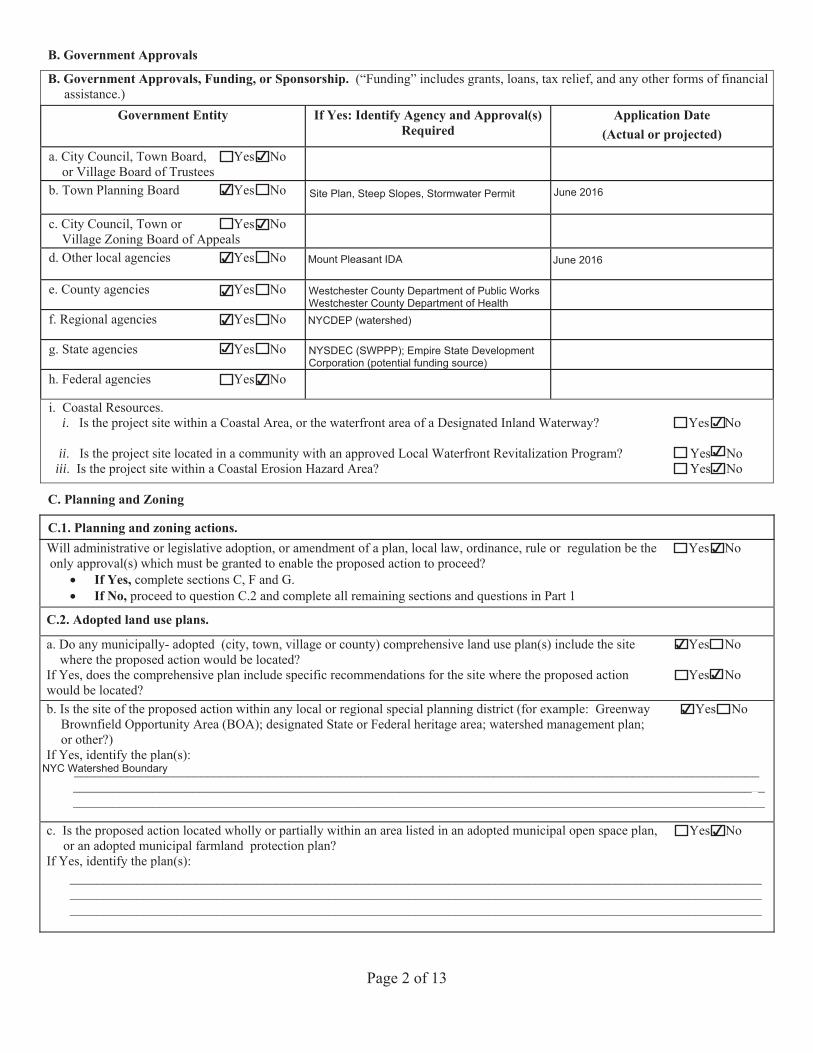
B. Government Approvals
B. Government Approvals Funding, or Sponsorship. (“Funding” includes grants, loans, tax relief, and any other forms of financialassistance.)
Government Entity If Yes: Identify Agency and Approval(s) Required
Application Date (Actual or projected)
a. City Council, Town Board, Yes Noor Village Board of Trustees
b. Town Yes No
c. City Council, Town or Yes No Village Zoning Board of Appeals
d. Other local agencies Yes No
e. County agencies Yes No
f. Regional agencies Yes No
g. State agencies Yes No
h. Federal agencies Yes No
i. Coastal Resources.i. Is the project site within a Coastal Area, or the waterfront area of a Designated Inland Waterway? Yes No
ii. Is the project site located in a community with an approved Local Waterfront Revitalization Program? Yes No iii. Is the project site within a Coastal Erosion Hazard Area? Yes No
C. Planning and Zoning
C.1. Planning and zoning actions. Will administrative or legislative adoption, or amendment of a plan, local law, ordinance, rule or regulation be the Yes No only approval(s) which must be granted to enable the proposed action to proceed?
If Yes, complete sections C, F and G.If No, proceed to question C.2 and complete all remaining sections and questions in Part 1
C.2. Adopted land use plans.
a. Do any municipally- adopted (city, town, village or county) comprehensive land use plan(s) include the site Yes No where the proposed action would be located?
If Yes, does the comprehensive plan include specific recommendations for the site where the proposed action Yes No would be located? b. Is the site of the proposed action within any local or regional special planning district (for example: Greenway Yes No
Brownfield Opportunity Area (BOA); designated State or Federal heritage area; watershed management plan;or other?)
If Yes, identify the plan(s): _______________________________________________________________________________________________________
________________________________________________________________________________________________________ ________________________________________________________________________________________________________
c. Is the proposed action located wholly or partially within an area listed in an adopted municipal open space plan, Yes Noor an adopted municipal farmland protection plan?
If Yes, identify the plan(s): ________________________________________________________________________________________________________ ________________________________________________________________________________________________________ ________________________________________________________________________________________________________
✔
✔ Site Plan, Steep Slopes, Stormwater Permit June 2016
✔
✔ Mount Pleasant IDA June 2016
✔ Westchester County Department of Public WorksWestchester County Department of Health
✔ NYCDEP (watershed)
✔ NYSDEC (SWPPP); Empire State DevelopmentCorporation (potential funding source)
✔
✔
✔
✔
✔
✔
✔
✔
NYC Watershed Boundary
✔
Page 3 of 13
C.3. Zoning
a. Is the site of the proposed action located in a municipality with an adopted zoning law or ordinance. Yes NoIf Yes, what is the zoning classification(s) including any applicable overlay district?
__________________________________________________________________________________________________________________________________________________________________________________________________________________
b. Is the use permitted or allowed by a special or conditional use permit? Yes No
c. Is a zoning change requested as part of the proposed action? Yes No If Yes,
i. What is the proposed new zoning for the site? ___________________________________________________________________
C.4. Existing community services.
a. In what school district is the project site located? ________________________________________________________________
b. What police or other public protection forces serve the project site? _________________________________________________________________________________________________________
c. Which fire protection and emergency medical services serve the project site?__________________________________________________________________________________________________________
d. What parks serve the project site?____________________________________________________________________________________________________________________________________________________________________________________________________________________
D. Project Details
D.1. Proposed and Potential Development
a. What is the general nature of the proposed action (e.g., residential, industrial, commercial, recreational; if mixed, include allcomponents)?_________________________________________________________________________________________________________
b. a. Total acreage of the site of the proposed action? ____ ____ acres b. Total acreage to be physically disturbed? __________ acres c. Total acreage (project site and any contiguous properties) owned
or controlled by the applicant or project sponsor? _________ acres
c. Is the proposed action an expansion of an existing project or use? Yes No i. If Yes, what is the approximate percentage of the proposed expansion and identify the units (e.g., acres, miles, housing units,
square feet)? % ____________________ Units: ____________________d. Is the proposed action a subdivision, or does it include a subdivision? Yes No If Yes,
i. Purpose or type of subdivision? (e.g., residential, industrial, commercial; if mixed, specify types) ________________________________________________________________________________________________________
ii. Is a cluster/conservation layout proposed? Yes No iii. Number of lots proposed? ________iv. Minimum and maximum proposed lot sizes? Minimum __________ Maximum __________
e. Will proposed action be constructed in multiple phases? Yes No i. If No, anticipated period of construction: _____ months
ii. If Yes:Total number of phases anticipated _____ Anticipated commencement date of phase 1 (including demolition) _____ month _____ year Anticipated completion date of final phase _____ month _____year Generally describe connections or relationships among phases, including any contingencies where progress of one phase maydetermine timing or duration of future phases: _______________________________________________________________ ____________________________________________________________________________________________________ ____________________________________________________________________________________________________
sg p pb. Total acreage to be physically disturbed?
______ ______________ acres
✔
OB-1 (Office-Business)
✔
✔
Valhalla Union Free School District
Mount Pleasant Police Department
Valhalla FD, Valhalla VAC, Valhalla EMS
Kensico Dam Plaza park, Mount Pleasant Pool and recreation area, Pat Henry Field, Cranberry Preserve, Graham Hills Park
35.099.9
35.09
✔
70%/approx. 137,000 sf
✔
✔30
expansion of existing research and development facility on existing suburban office campus.
Page 4 of 13
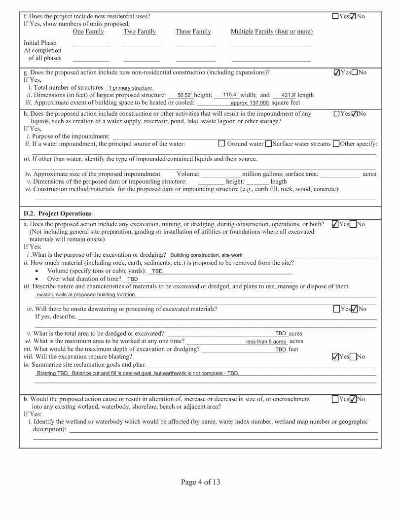
f. Does the project include new residential uses? Yes No If Yes, show numbers of units proposed.
One Family Two Family Three Family Multiple Family (four or more)
Initial Phase ___________ ___________ ____________ ________________________ At completion of all phases ___________ ___________ ____________ ________________________
g. Does the proposed action include new non-residential construction (including expansions)? Yes No If Yes,
i. Total number of structures __ _________ii. Dimensions (in feet) of largest proposed structure: ________height; ________width; and _______ length
iii. Approximate extent of building space to be heated or cooled: ______________________ square feet
h. Does the proposed action include construction or other activities that will result in the impoundment of any Yes No liquids, such as creation of a water supply, reservoir, pond, lake, waste lagoon or other storage?
If Yes, i. Purpose of the impoundment: ________________________________________________________________________________
ii. If a water impoundment, the principal source of the water: Ground water Surface water streams Other specify:_________________________________________________________________________________________________________
iii. If other than water, identify the type of impounded/contained liquids and their source._________________________________________________________________________________________________________
iv. Approximate size of the proposed impoundment. Volume: ____________ million gallons; surface area: ____________ acres v. Dimensions of the proposed dam or impounding structure: ________ height; _______ length
vi. Construction method/materials for the proposed dam or impounding structure (e.g., earth fill, rock, wood, concrete):________________________________________________________________________________________________________
D.2. Project Operations a. Does the proposed action include any excavation, mining, or dredging, during construction, operations, or both? Yes No
(Not including general site preparation, grading or installation of utilities or foundations where all excavatedmaterials will remain onsite)
If Yes:i .What is the purpose of the excavation or dredging? _______________________________________________________________
ii. How much material (including rock, earth, sediments, etc.) is proposed to be removed from the site?Volume (specify tons or cubic yards): ____________________________________________Over what duration of time? ____________________________________________________
iii. Describe nature and characteristics of materials to be excavated or dredged, and plans to use, manage or dispose of them. ________________________________________________________________________________________________________ ________________________________________________________________________________________________________
iv. Will there be onsite dewatering or processing of excavated materials? Yes No If yes, describe. ___________________________________________________________________________________________ ________________________________________________________________________________________________________
v. What is the total area to be dredged or excavated? _____________________________________acresvi. What is the maximum area to be worked at any one time? _______________________________ acres
vii. What would be the maximum depth of excavation or dredging? __________________________ feetviii. Will the excavation require blasting? Yes No ix. Summarize site reclamation goals and plan: _____________________________________________________________________
________________________________________________________________________________________________________ ________________________________________________________________________________________________________
b. Would the proposed action cause or result in alteration of, increase or decrease in size of, or encroachment Yes No into any existing wetland, waterbody, shoreline, beach or adjacent area?
If Yes: i. Identify the wetland or waterbody which would be affected (by name, water index number, wetland map number or geographic
description): _______________________________________________________________________________________________________________________________________________________________________________________________________
✔
✔
1 primary structure50.52' 115.4 ' 421.9'
approx. 137,000
✔
✔
Building construction, site work
TBDTBD
existing soils at proposed building location.
✔
TBDless than 5 acres
TBD✔
Blasting TBD. Balance cut and fill is desired goal, but earthwork is not complete - TBD.
✔
Page 5 of 13
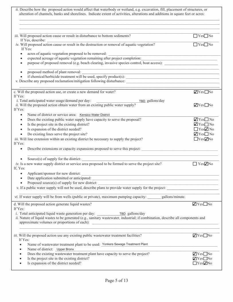
ii. Describe how the proposed action would affect that waterbody or wetland, e.g. excavation, fill, placement of structures, oralteration of channels, banks and shorelines. Indicate extent of activities, alterations and additions in square feet or acres:____________________________________________________________________________________________________________________________________________________________________________________________________________________________________________________________________________________________________________________________________________________________________________________________________________________________________
iii. Will proposed action cause or result in disturbance to bottom sediments? Yes NoIf Yes, describe: __________________________________________________________________________________________
iv. Will proposed action cause or result in the destruction or removal of aquatic vegetation? Yes No If Yes:
a of vegetation proposed to be removed ___________________________________________________________ acreage of aquatic vegetation remaining after project completion ________________________________________
purpose of proposed removal (e.g. beach clearing, invasive species control, boat access): ________________________________________________________________________________________________________________________________
proposed method of plant removal: ________________________________________________________________________if chemical/herbicide treatment will be used, specify product(s): _________________________________________________
v. Describe any proposed reclamation/mitigation following disturbance: __________________________________________________________________________________________________________________________________________________________
c. Will the proposed action use, or create a new demand for water? Yes No If Yes:
i. Total anticipated water usage/demand per day: __________________________ gallons/dayii. Will the proposed action obtain water from an existing public water supply? Yes No
If Yes:Name of district or service area: _________________________________________________________________________Does the existing public water supply have capacity to serve the proposal? Yes No Is the project site in the existing district? Yes No Is expansion of the district needed? Yes No Do existing lines serve the project site? Yes No
iii. Will line extension within an existing district be necessary to supply the project? Yes No If Yes:
Describe extensions or capacity expansions proposed to serve this project: ____________________________________________________________________________________________________________________________________________ Source(s) of supply for the district: ________________________________________________________________________
iv. Is a new water supply district or service area proposed to be formed to serve the project site? Yes No If, Yes:
Applicant/sponsor for new district: ________________________________________________________________________Date application submitted or anticipated: __________________________________________________________________Proposed source(s) of supply for new district: _______________________________________________________________
v. If a public water supply will not be used, describe plans to provide water supply for the project: ____________________________________________________________________________________________________________________________________
vi. If water supply will be from wells (public or private), maximum pumping capacity: _______ gallons/minute.
d. Will the proposed action generate liquid wastes? Yes No If Yes:
i. Total anticipated liquid waste generation per day: _______________ gallons/dayii. Nature of liquid wastes to be generated (e.g., sanitary wastewater, industrial; if combination, describe all components and
approximate volumes or proportions of each): ____________________________________________________________________________________________________________________________________________________________________________________________________________________________________________________________________________________
iii. Will the proposed action use any existing public wastewater treatment facilities? Yes No If Yes:
Name of wastewater treatment plant to be used: _____________________________________________________________Name of district: ______________________________________________________________________________________Does the existing wastewater treatment plant have capacity to serve the project? Yes No
Is the project site in the existing district? Yes No Is expansion of the district needed? Yes No
✔
TBD✔
Kensico Water District✔✔
✔✔
✔
✔
✔
TBD
✔
Yonkers Sewage Treatment PlantUpper Bronx
✔✔
✔
Page 6 of 13
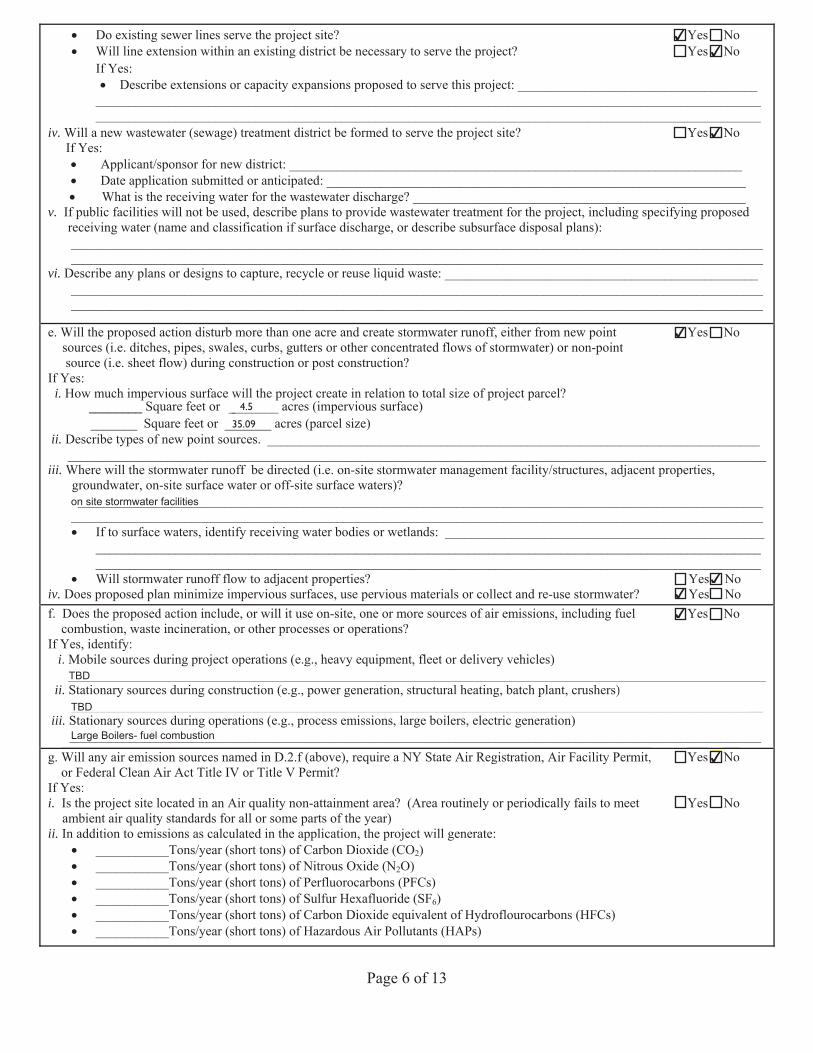
Do existing sewer lines serve the project site? Yes No Will line extension within an existing district be necessary to serve the project? Yes No If Yes:
Describe extensions or capacity expansions proposed to serve this project: ________________________________________________________________________________________________________________________________________ ____________________________________________________________________________________________________
iv. Will a new wastewater (sewage) treatment district be formed to serve the project site? Yes No If Yes:
Applicant/sponsor for new district: ____________________________________________________________________Date application submitted or anticipated: _______________________________________________________________What is the receiving water for the wastewater discharge? __________________________________________________
v. If public facilities will not be used, describe plans to provide wastewater treatment for the project, including specifying proposed receiving water (name and classification if surface discharge, or describe subsurface disposal plans): ________________________________________________________________________________________________________ ________________________________________________________________________________________________________
vi. Describe any plans or designs to capture, recycle or reuse liquid waste: _______________________________________________ ________________________________________________________________________________________________________ ________________________________________________________________________________________________________
e. Will the proposed action disturb more than one acre and create stormwater runoff, either from new point Yes No sources (i.e. ditches, pipes, swales, curbs, gutters or other concentrated flows of stormwater) or non-point
source (i.e. sheet flow) during construction or post construction? If Yes:
i. How much impervious surface will the project create in relation to total size of project parcel?_ Square feet or __ __ acres (impervious surface)
_ _ Square feet or acres (parcel size)ii. Describe types of new point sources. __________________________________________________________________________
_________________________________________________________________________________________________________iii. Where will the stormwater runoff be directed (i.e. on-site stormwater management facility/structures, adjacent properties,
groundwater, on-site surface water or off-site surface waters)? ________________________________________________________________________________________________________
________________________________________________________________________________________________________ If to surface waters, identify receiving water bodies or wetlands: ________________________________________________________________________________________________________________________________________________________________________________________________________________________________________________________Will stormwater runoff flow to adjacent properties? Yes No
iv. Does proposed plan minimize impervious surfaces, use pervious materials or collect and re-use stormwater? Yes No f. Does the proposed action include, or will it use on-site, one or more sources of air emissions, including fuel Yes No
combustion, waste incineration, or other processes or operations?If Yes, identify:
i. Mobile sources during project operations (e.g., heavy equipment, fleet or delivery vehicles)_________________________________________________________________________________________________________
ii. Stationary sources during construction (e.g., power generation, structural heating, batch plant, crushers)________________________________________________________________________________________________________
iii. Stationary sources during operations (e.g., process emissions, large boilers, electric generation)________________________________________________________________________________________________________
g. Will any air emission sources named in D.2.f (above), require a NY State Air Registration, Air Facility Permit, Yes No or Federal Clean Air Act Title IV or Title V Permit?
If Yes:i. Is the project site located in an Air quality non-attainment area? (Area routinely or periodically fails to meet Yes No
ambient air quality standards for all or some parts of the year)ii. In addition to emissions as calculated in the application, the project will generate:
___________Tons/year ( ) of Carbon Dioxide (CO2)___________Tons/year ( ) of Nitrous Oxide (N2 )___________Tons/year ( ) of Perfluorocarbons (PFCs)___________Tons/year ( ) of Sulfur Hexafluoride (SF6)___________Tons/year ( ) of Carbon Dioxide equivalent of Hydroflo rocarbons (H )___________Tons/year ( ) of Hazardous Air Pollutants (HAPs)
35.09
Will any air emission sources named in D.2.f (above), require a NY State Air Registration, Air Facility Permit,tt Yes No y (or Federal Clean Air Act Title IV or Title V Permit?
If Yes:
, yMobile sources during project operations (e.g., heavy equipment, fleet or delivery vehicles)g p j p ( g , y q p , y )_________________________________________________________________________________________________________Stationary sources during construction (e.g., power generation, structural heating, batch plant, crushers)____________________________________________________________________________________
y g ( g , p g , g, p , )y g ( g , p g , g, p , )__________________________________________________________________________________________________________
4.5
✔✔
✔
✔
on site stormwater facilities
✔✔
✔
TBD
TBD
Large Boilers- fuel combustion
✔
Page 7 of 13
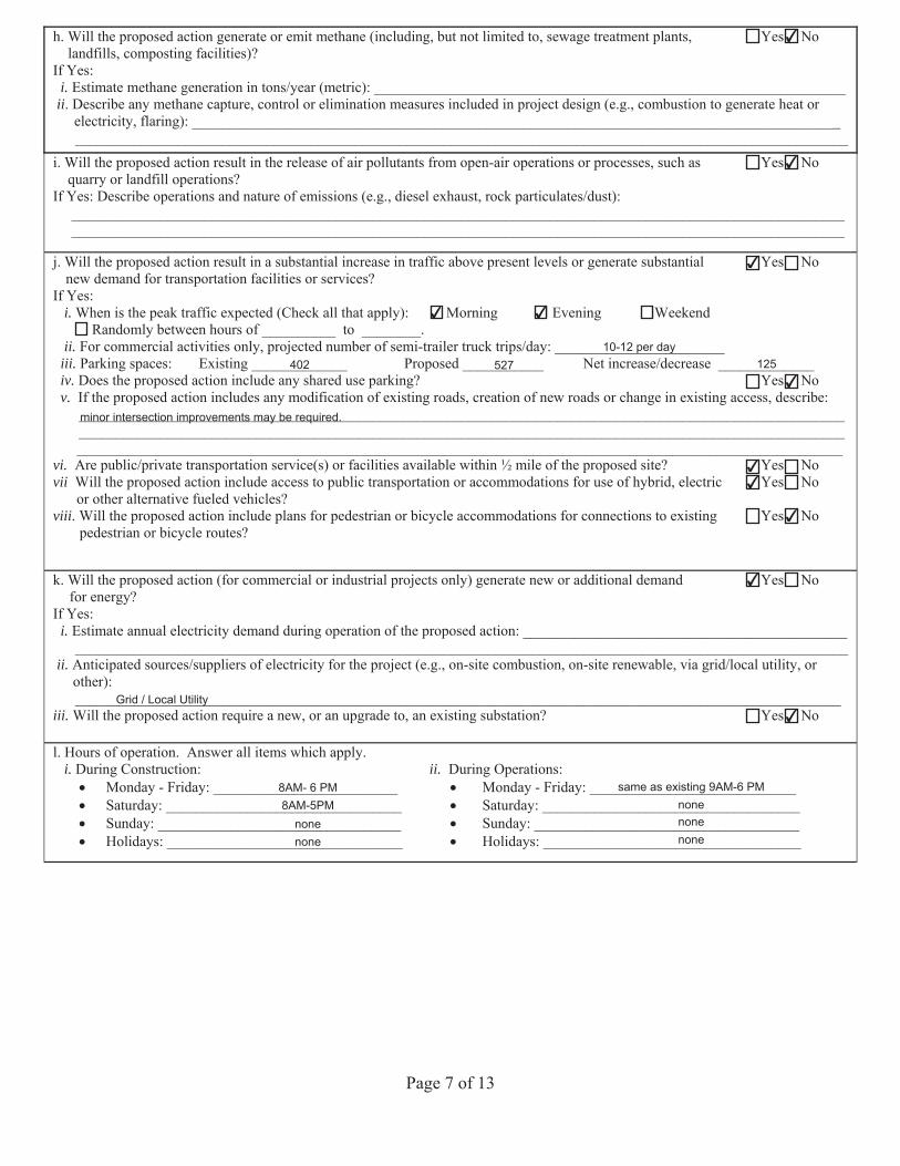
h. Will the proposed action generate or emit methane (including, but not limited to, sewage treatment plants, Yes No landfills, composting facilities)?
If Yes:i. Estimate methane generation in tons/year (metric): ________________________________________________________________
ii. Describe any methane capture, control or elimination measures included in project design (e.g., combustion to generate heat orelectricity, flaring): _________________________________________________________________________________________________________________________________________________________________________________________________
i. Will the proposed action result in the release of air pollutants from open-air operations or processes, such as Yes No quarry or landfill operations?
If Yes: Describe operations and nature of emissions (e.g., diesel exhaust, rock particulates/dust): _________________________________________________________________________________________________________ _________________________________________________________________________________________________________
j. Will the proposed action result in a substantial increase in traffic above present levels or generate substantial Yes No new demand for transportation facilities or services?
If Yes:i. When is the peak traffic expected (Check all that apply): Morning Evening Weekend
Randomly between hours of __________ to ________.ii. For commercial activities only, projected number of semi-trailer truck trips/day: _______________________
iii. Parking spaces: Existing _____________ Proposed ___________ Net increase/decrease _____________iv. Does the proposed action include any shared use parking? Yes No v. If the proposed action includes any modification of existing roads, creation of new roads or change in existing access, describe:
________________________________________________________________________________________________________________________________________________________________________________________________________________________________________________________________________________________________________________________
vi. Are public/private transportation service(s) or facilities available within ½ mile of the proposed site? Yes No vii Will the proposed action include access to public transportation or accommodations for use of hybrid, electric Yes No
or other alternative fueled vehicles? viii. Will the proposed action include plans for pedestrian or bicycle accommodations for connections to existing Yes No
pedestrian or bicycle routes?
k. Will the proposed action (for commercial or industrial projects only) generate new or additional demand Yes No for energy?
If Yes:i. Estimate annual electricity demand during operation of the proposed action: ____________________________________________
_________________________________________________________________________________________________________ii. Anticipated sources/suppliers of electricity for the project (e.g., on-site combustion, on-site renewable, via grid/local utility, or
other):________________________________________________________________________________________________________
iii. Will the proposed action require a new, or an upgrade to, an existing substation? Yes No
l. Hours of operation. Answer all items which apply.i. During Construction: ii. During Operations:
Monday - Friday: _________________________ Monday - Friday: ____________________________Saturday: ________________________________ Saturday: ___________________________________Sunday: _________________________________ Sunday: ____________________________________Holidays: ________________________________ Holidays: ___________________________________
✔
✔
✔
✔ ✔
10-12 per day402 527 125
✔
minor intersection improvements may be required.
✔✔
✔
✔
Grid / Local Utility✔
8AM- 6 PM8AM-5PM
nonenone
same as existing 9AM-6 PMnonenonenone
Page 8 of 13
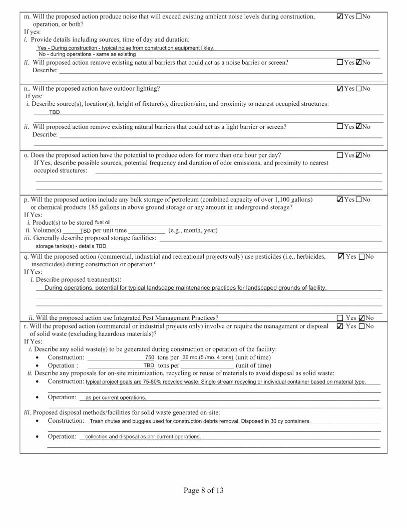
m. Will the proposed action produce noise that will exceed existing ambient noise levels during construction, Yes No operation, or both?
If yes: i. Provide details including sources, time of day and duration:
_______________________________________________________________________________________________________ _______________________________________________________________________________________________________
ii. Will proposed action remove existing natural barriers that could act as a noise barrier or screen? Yes No Describe: _________________________________________________________________________________________________ _________________________________________________________________________________________________________
n.. Will the proposed action have outdoor lighting? Yes No If yes: i. Describe source(s), location(s), height of fixture(s), direction/aim, and proximity to nearest occupied structures:
_________________________________________________________________________________________________________ _________________________________________________________________________________________________________
ii. Will proposed action remove existing natural barriers that could act as a light barrier or screen? Yes No Describe: _________________________________________________________________________________________________ _________________________________________________________________________________________________________
o. Does the proposed action have the potential to produce odors for more than one hour per day? Yes No If Yes, describe possible sources, potential frequency and duration of odor emissions, and proximity to nearest occupied structures: ______________________________________________________________________________________
________________________________________________________________________________________________________ ________________________________________________________________________________________________________
p. Yes No Will the proposed action include any bulk storage of petroleum ( over 1,100 gallons)or chemical products ?
If Yes: i. Product(s) to be stored ______________________________________________________________________________________
ii. Volume(s) ______ per unit time ___________ (e.g., month, year)iii. Generally describe proposed storage facilities ___________________________________________________________________
________________________________________________________________________________________________________q. Will the proposed action (commercial, industrial and recreational projects only) use pesticides (i.e., herbicides, Yes No
insecticides) during construction or operation?If Yes:
i. Describe proposed treatment(s):________________________________________________________________________________________________________________________________________________________________________________________________________________________________________________________________________________________________________________________________________________________________________________________________________________________________
ii. Will the proposed action use Integrated Pest Management Practices? Yes No r. Will the proposed action (commercial or industrial projects only) involve or require the management or disposal Yes No
of solid waste (excluding hazardous materials)?If Yes:
i. Describe any solid waste(s) to be generated during construction or operation of the facility:Construction: ____________________ tons per ________________ (unit of time)Operation : ____________________ tons per ________________ (unit of time)
ii. Describe any proposals for on-site minimization, recycling or reuse of materials to avoid disposal as solid waste:Construction: ____________________________________________________________________________________________________________________________________________________________________________________________Operation: ______________________________________________________________________________________________________________________________________________________________________________________________
iii. Proposed disposal methods/facilities for solid waste generated on-site:Construction: ____________________________________________________________________________________________________________________________________________________________________________________________Operation: ______________________________________________________________________________________________________________________________________________________________________________________________
✔
Yes - During construction - typical noise from construction equipment likley.No - during operations - same as existing
✔
✔
TBD
✔
✔
✔
fuel oilTBD
storage tanks(s) - details TBD
✔
During operations, potential for typical landscape maintenance practices for landscaped grounds of facility.
✔✔
750TBD
36 mo.(5 /mo. 4 tons)
typical project goals are 75-80% recycled waste. Single stream recycling or individual container based on material type.
as per current operations.
Trash chutes and buggies used for construction debris removal. Disposed in 30 cy containers.
collection and disposal as per current operations.
Page 9 of 13
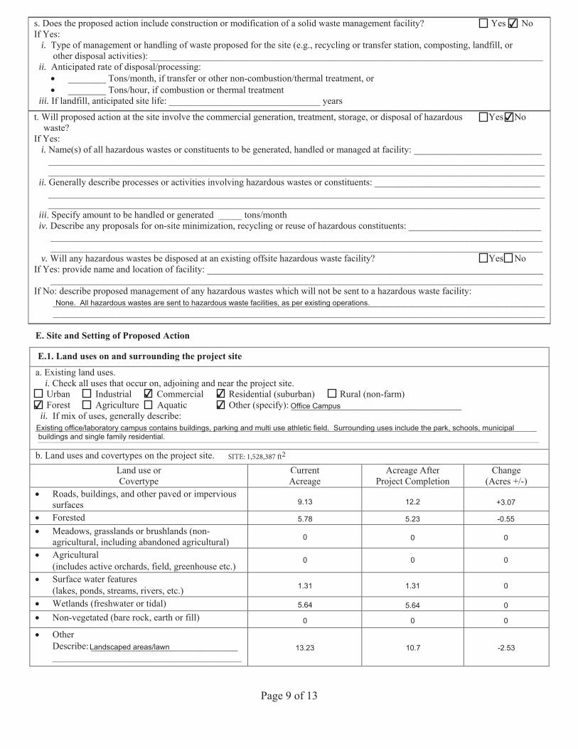
s. Does the proposed action include construction or modification of a solid waste management facility? Yes No If Yes:
i. Type of management or handling of waste proposed for the site (e.g., recycling or transfer station, composting, landfill, orother disposal activities): ___________________________________________________________________________________
ii. Anticipated rate of disposal/processing:________ Tons/month, if transfer or other non-combustion/thermal treatment, or________ Tons/hour, if combustion or thermal treatment
iii. If landfill, anticipated site life: ________________________________ years
t. Will proposed action at the site involve the commercial generation, treatment, storage, or disposal of hazardous Yes No waste?
If Yes: i. Name(s) of all hazardous wastes or constituents to be generated, handled or managed at facility: ___________________________
__________________________________________________________________________________________________________________________________________________________________________________________________________________
ii. Generally describe processes or activities involving hazardous wastes or constituents: ____________________________________________________________________________________________________________________________________________________________________________________________________________________________________________________
iii. Specify amount to be handled or generated _____ tons/monthiv. Describe any proposals for on-site minimization, recycling or reuse of hazardous constituents: ____________________________
________________________________________________________________________________________________________________________________________________________________________________________________________________
v. Will any hazardous wastes be disposed at an existing offsite hazardous waste facility? Yes No If Yes: provide name and location of facility: _______________________________________________________________________ ________________________________________________________________________________________________________ If No: describe proposed management of any hazardous wastes which will not be sent to a hazardous waste facility:
________________________________________________________________________________________________________ ________________________________________________________________________________________________________
E. Site and Setting of Proposed Action
E.1. Land uses on and surrounding the project site a. Existing land uses.
i. Check all uses that occur on, adjoining and near the project site. Urban Industrial Commercial Residential (suburban) Rural (non-farm) Forest Agriculture Aquatic Other (specify): ____________________________________ ii. If mix of uses, generally describe:
__________________________________________________________________________________________________________ __________________________________________________________________________________________________________
b. Land uses and covertypes on the project site.Land use or Covertype
Current Acreage
Acreage After Project Completion
Change (Acres +/-)
Roads, buildings, and other paved or impervioussurfacesForestedMeadows, grasslands or brushlands (non-agricultural, including abandoned agricultural)Agricultural(includes active orchards, field, greenhouse etc.) Surface water features(lakes, ponds, streams, rivers, etc.) Wetlands (freshwater or tidal)Non-vegetated (bare rock, earth or fill)
OtherDescribe: _______________________________ ________________________________________
Acreage After ChangegProject Completion
g(Acres +/-)
Current Acreage
✔
✔
None. All hazardous wastes are sent to hazardous waste facilities, as per existing operations.
✔ ✔✔ ✔ Office Campus
Existing office/laboratory campus contains buildings, parking and multi use athletic field. Surrounding uses include the park, schools, municipalbuildings and single family residential.
9.13 12.2 +3.07
5.78 5.23 -0.55
0 0 0
0 0 0
1.31 1.31 0
5.64 5.64 0
0 0 0
Landscaped areas/lawn 13.23 10.7 -2.53
Page 10 of 13
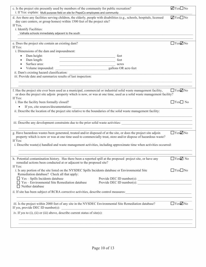
c. Is the project site presently used by members of the community for public recreation? Yes No i. If Yes: explain: __________________________________________________________________________________________
d. Are there any facilities serving children, the elderly, people with disabilities (e.g., schools, hospitals, licensed Yes No day care centers, or group homes) within 1500 feet of the project site?
If Yes, i. Identify Facilities:
________________________________________________________________________________________________________________________________________________________________________________________________________________
e. Does the project site contain an existing dam? Yes No If Yes:
i. Dimensions of the dam and impoundment:Dam height: _________________________________ feet Dam length: _________________________________ feet Surface area: _________________________________ acres Volume impounded: _______________________________ gallons OR acre-feet
ii. Dam=s existing hazard classification: _________________________________________________________________________iii. Provide date and summarize results of last inspection:
_______________________________________________________________________________________________________ _______________________________________________________________________________________________________
f. Has the project site ever been used as a municipal, commercial or industrial solid waste management facility, Yes No or does the project site adjoin property which is now, or was at one time, used as a solid waste management facility?
If Yes:i. Has the facility been formally closed? Yes No
If yes, cite sources/documentation: _______________________________________________________________________ii. Describe the location of the project site relative to the boundaries of the solid waste management facility:
______________________________________________________________________________________________________________________________________________________________________________________________________________
iii. Describe any development constraints due to the prior solid waste activities: _________________________________________________________________________________________________________________________________________________
g. Have hazardous wastes been generated, treated and/or disposed of at the site, or does the project site adjoin Yes No property which is now or was at one time used to commercially treat, store and/or dispose of hazardous waste?
If Yes:i. Describe waste(s) handled and waste management activities, including approximate time when activities occurred:
_______________________________________________________________________________________________________ _______________________________________________________________________________________________________
h. Potential contamination history. Has there been a reported spill at the proposed project site, or have any Yes No remedial actions been conducted at or adjacent to the proposed site?
If Yes: i. Is any portion of the site listed on the NYSDEC Spills Incidents database or Environmental Site Yes No
Remediation database? Check all that apply: Yes – Spills Incidents database Provide DEC ID number(s): ________________________________ Yes – Environmental Site Remediation database Provide DEC ID number(s): ________________________________ Neither database
ii. If site has been subject of RCRA corrective activities, describe control measures:_______________________________________________________________________________________________________________________________________________________________________________________________________________________________________________________
iii. Is the project within 2000 feet of any site in the NYSDEC Environmental Site Remediation database? Yes No If yes, provide DEC ID number(s): ______________________________________________________________________________ iv. If yes to (i), (ii) or (iii) above, describe current status of site(s):
_______________________________________________________________________________________________________ _______________________________________________________________________________________________________
✔
Multi purpose field on site for PepsiCo employees and community
✔
Valhalla schools immediately adjacent to the south
✔
✔
✔
✔
✔
Page 11 of 13
v. Is the project site subject to an institutional control limiting property uses? Yes No If yes, DEC site ID number: ____________________________________________________________________________Describe the type of institutional control (e.g., deed restriction or easement): ____________________________________Describe any use limitations: ___________________________________________________________________________Describe any engineering controls: _______________________________________________________________________Will the project affect the institutional or engineering controls in place? Yes No Explain: _______________________________________________________________________________________________________________________________________________________________________________________________
___________________________________________________________________________________________________
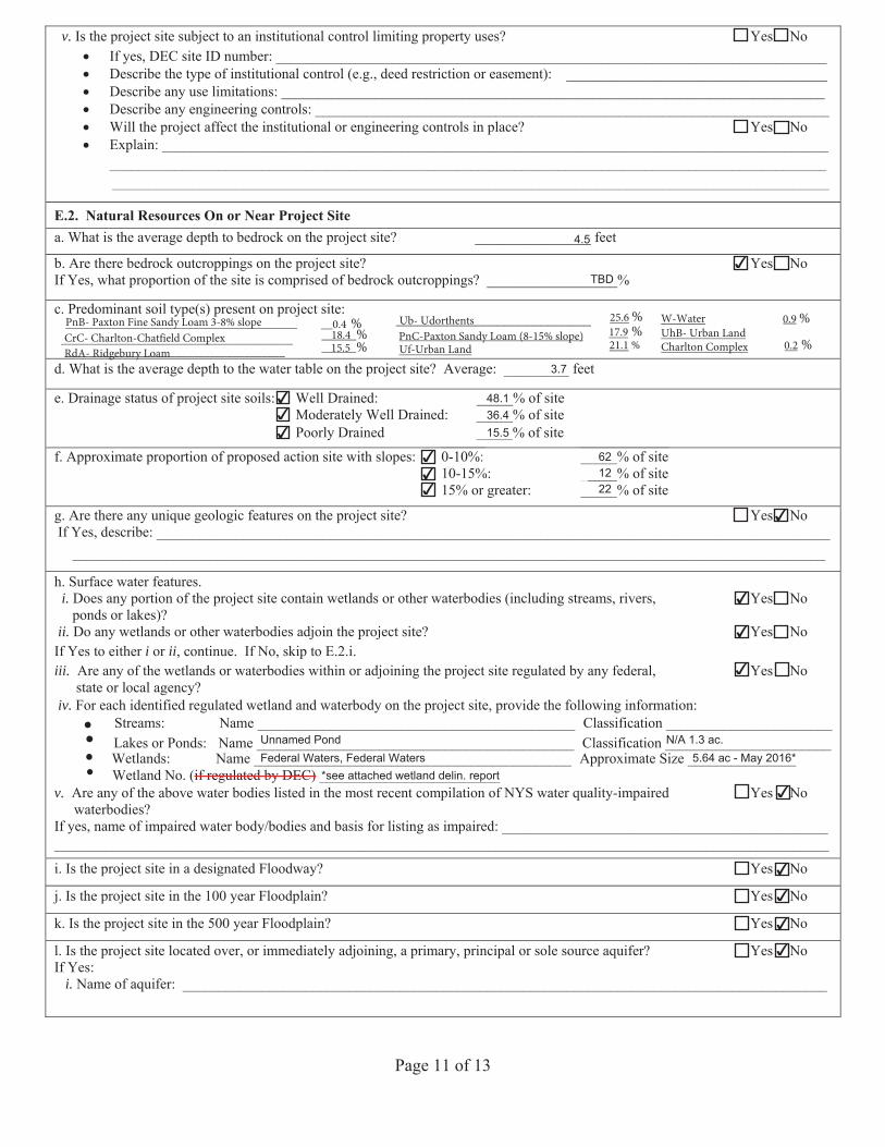
E.2. Natural Resources On or Near Project Sitea. What is the average depth to bedrock on the project site? ________________ feet
b. Are there bedrock outcroppings on the project site? Yes No If Yes, what proportion of the site is comprised of bedrock outcroppings? __________________%
c. Predominant soil type(s) present on project site: ___________________________
d. What is the average depth to the water table on the project site? Average: _________ feet
e. Drainage status of project site soils: Well Drained: ___ _% of ite Moderately Well Drained: _____% of site Poorly Drained _____% of ite
f. Approximate proportion of proposed action site with slopes: 0-10%: _____% of site 10-15%: _____% of site 15% or greater: _____% of site
g. Are there any unique geologic features on the project site? Yes No If Yes, describe: _____________________________________________________________________________________________
________________________________________________________________________________________________________
h. Surface water features.i. Does any portion of the project site contain wetlands or other waterbodies (including streams, rivers, Yes No
ponds or lakes)?ii. Do any wetlands or other waterbodies adjoin the project site? Yes No
If Yes to either i or ii, continue. If No, skip to E.2.i.iii. Are any of the wetlands or waterbodies within or adjoining the project site regulated by any federal, Yes No
state or local agency?iv. For each identified wetland and waterbody on the project site, provide the following information
Streams: Name ____________________________________________ Classification _______________________ Lakes or Ponds: Name ____________________________________________ Classification _______________________Wetlands: Name ____________________________________________ Approximate Size _______________ Wetland No. (if regulated by DEC) _________________________
v. Are any of the above water bodies listed in the most recent compilation of NYS water quality-impaired Yes No waterbodies?
If yes, name of impaired water body/bodies and basis for listing as impaired: _____________________________________________ ___________________________________________________________________________________________________________
i. Is the project site in a designated Floodway? Yes No
j. Is the project site in the 100 year Floodplain? Yes No
k. Is the project site in the 500 year Floodplain? Yes No
l. Is the project site located over, or immediately adjoining, a primary, principal or sole source aquifer? Yes No If Yes:
i. Name of aquifer: _________________________________________________________________________________________
0-10%: _____% of site 10-15%:
__________% of site
4.5
✔TBD
3.7
✔ 48.1✔ 36.4✔ 15.5
✔ 62✔ 12✔ 22
✔
✔
✔
✔
Unnamed Pond N/A 1.3 ac.Federal Waters, Federal Waters 5.64 ac - May 2016*
*see attached wetland delin. report✔
✔
✔
✔
✔
Page 12 of 13
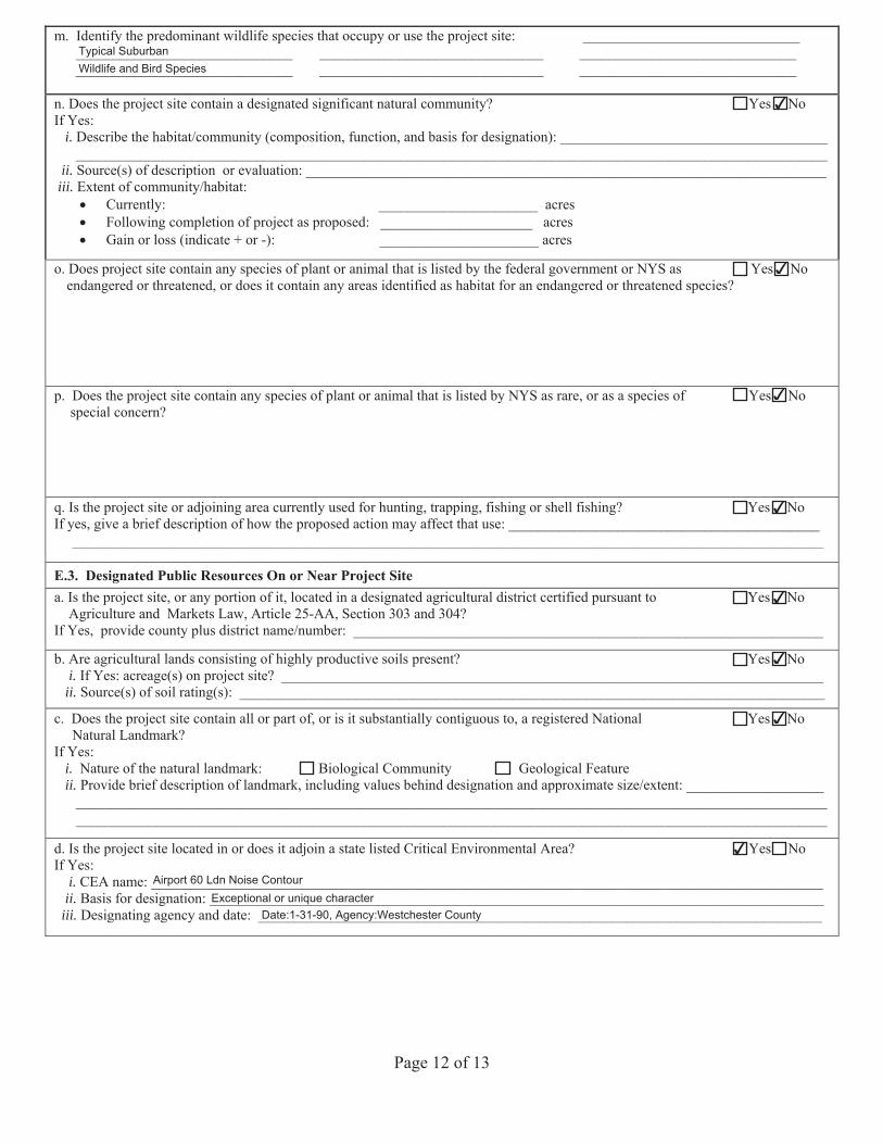
m. Identify the predominant wildlife species that occupy or use the project site: ______________________________ ______________________________ _______________________________ ______________________________ ______________________________ _______________________________ ______________________________
n. Does the project site contain a designated significant natural community? Yes No If Yes:
i. Describe the habitat/community (composition, function, and basis for designation): _____________________________________ ________________________________________________________________________________________________________
ii. Source(s) of description or evaluation: ________________________________________________________________________iii. Extent of community/habitat:
Currently: ______________________ acres Following completion of project as proposed: _____________________ acresGain or loss (indicate + or -): ______________________ acres
o. Does project site contain any species of plant or animal that is listed by the federal government or NYS as Yes No endangered or threatened, or does it contain any areas identified as habitat for an endangered or threatened species?
p. Does the project site contain any species of plant or animal that is listed by NYS as rare, or as a species of Yes Nospecial concern?
q. Is the project site or adjoining area currently used for hunting, trapping, fishing or shell fishing? Yes No If yes, give a brief description of how the proposed action may affect that use: ___________________________________________
________________________________________________________________________________________________________
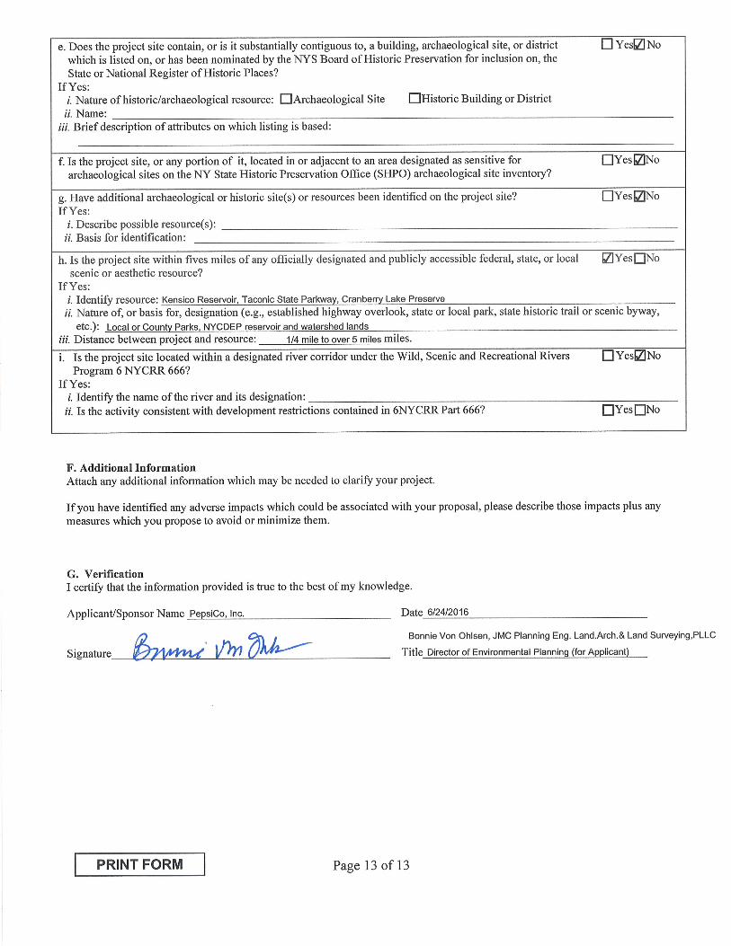
E.3. Designated Public Resources On or Near Project Site a. Is the project site, or any portion of it, located in a designated agricultural district certified pursuant to Yes No
Agriculture and Markets Law, Article 25-AA, Section 303 and 304?If Yes, provide county plus district name/number: _________________________________________________________________
b. Are agricultural lands consisting of highly productive soils present? Yes No i. If Yes: acreage(s) on project site? ___________________________________________________________________________
ii. Source(s) of soil rating(s): _________________________________________________________________________________
c. Does the project site contain all or part of, or is it substantially contiguous to, a registered National Yes No Natural Landmark?
If Yes:i. Nature of the natural landmark: Biological Community Geological Featureii. Provide brief description of landmark, including values behind designation and approximate size/extent: ___________________
________________________________________________________________________________________________________ ________________________________________________________________________________________________________
d. Is the project site located in or does it adjoin a state listed Critical Environmental Area? Yes No If Yes:
i. CEA name: _____________________________________________________________________________________________ii. Basis for designation: _____________________________________________________________________________________
iii. Designating agency and date: ______________________________________________________________________________
Typical SuburbanWildlife and Bird Species
✔
✔
✔
✔
✔
✔
✔
Airport 60 Ldn Noise ContourExceptional or unique character
Date:1-31-90, Agency:Westchester County
✔
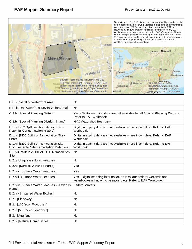
EAF Mapper Summary Report Friday, June 24, 2016 11:00 AM
Disclaimer: The EAF Mapper is a screening tool intended to assist project sponsors and reviewing agencies in preparing an environmental assessment form (EAF). Not all questions asked in the EAF are answered by the EAF Mapper. Additional information on any EAF question can be obtained by consulting the EAF Workbooks. Although the EAF Mapper provides the most up-to-date digital data available to DEC, you may also need to contact local or other data sources in order to obtain data not provided by the Mapper. Digital data is not a substitute for agency determinations.
B.i.i [Coastal or Waterfront Area] No
B.i.ii [Local Waterfront Revitalization Area] No
C.2.b. [Special Planning District] Yes - Digital mapping data are not available for all Special Planning Districts. Refer to EAF Workbook.
C.2.b. [Special Planning District - Name] NYC Watershed Boundary
E.1.h [DEC Spills or Remediation Site -Potential Contamination History]
Digital mapping data are not available or are incomplete. Refer to EAF Workbook.
E.1.h.i [DEC Spills or Remediation Site -Listed]
Digital mapping data are not available or are incomplete. Refer to EAF Workbook.
E.1.h.i [DEC Spills or Remediation Site -Environmental Site Remediation Database]
Digital mapping data are not available or are incomplete. Refer to EAF Workbook.
E.1.h.iii [Within 2,000' of DEC RemediationSite]
No
E.2.g [Unique Geologic Features] No
E.2.h.i [Surface Water Features] Yes
E.2.h.ii [Surface Water Features] Yes
E.2.h.iii [Surface Water Features] Yes - Digital mapping information on local and federal wetlands and waterbodies is known to be incomplete. Refer to EAF Workbook.
E.2.h.iv [Surface Water Features - WetlandsName]
Federal Waters
E.2.h.v [Impaired Water Bodies] No
E.2.i. [Floodway] No
E.2.j. [100 Year Floodplain] No
E.2.k. [500 Year Floodplain] No
E.2.l. [Aquifers] No
E.2.n. [Natural Communities] No
1Full Environmental Assessment Form - EAF Mapper Summary Report
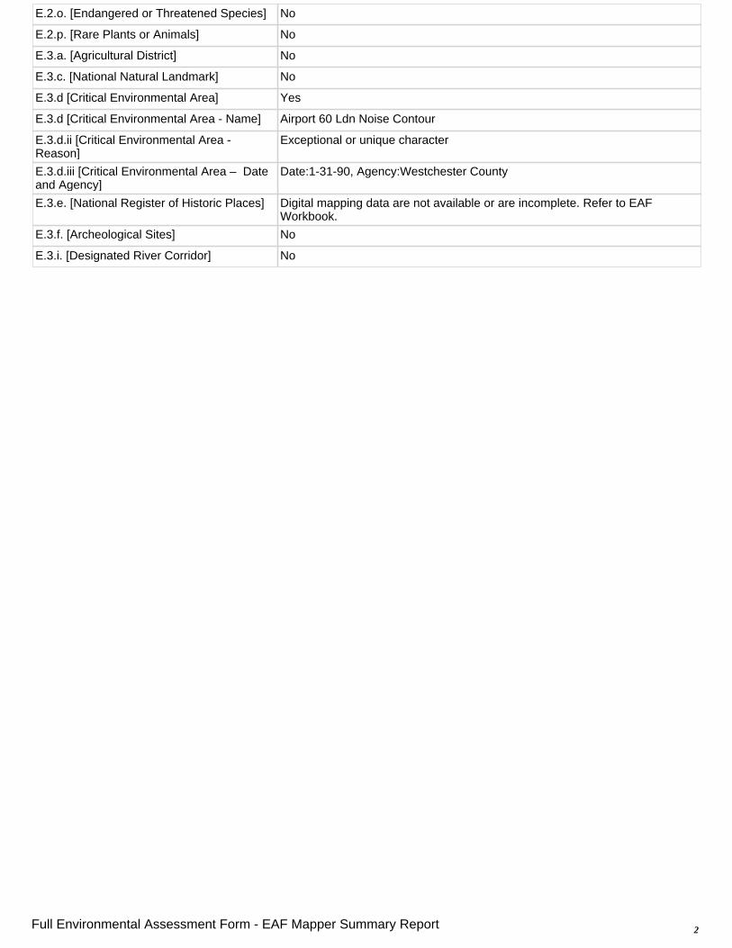
E.2.o. [Endangered or Threatened Species] No
E.2.p. [Rare Plants or Animals] No
E.3.a. [Agricultural District] No
E.3.c. [National Natural Landmark] No
E.3.d [Critical Environmental Area] Yes
E.3.d [Critical Environmental Area - Name] Airport 60 Ldn Noise Contour
E.3.d.ii [Critical Environmental Area - Reason]
Exceptional or unique character
E.3.d.iii [Critical Environmental Area – Date and Agency]
Date:1-31-90, Agency:Westchester County
E.3.e. [National Register of Historic Places] Digital mapping data are not available or are incomplete. Refer to EAF Workbook.
E.3.f. [Archeological Sites] No
E.3.i. [Designated River Corridor] No
2Full Environmental Assessment Form - EAF Mapper Summary Report
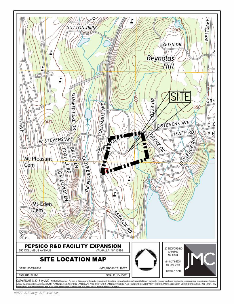
FIGURE: SLM-1
DATE: 06/24/2016
350 COLUMBUS AVENUE
SITE LOCATION MAPVALHALLA, NY 10595
SCALE: 1"=1000'
JMC PROJECT: 16077
PEPSICO R&D FACILITY EXPANSION
COPYRIGHT © 2016 by JMC All Rights Reserved. No part of this document may be reproduced, stored in a retrieval system, or transmitted in any form or by means, electronic, mechanical, photocopying, recording or otherwise,without the prior written permission of JMC PLANNING, ENGINEERING, LANDSCAPE ARCHITECTURE & LAND SURVEYING, PLLC | JMC SITE DEVELOPMENT CONSULTANTS, LLC | JOHN MEYER CONSULTING, INC. (JMC). Anymodifications or alterations to this document without the written permission of JMC shall render them invalid and unusable.
120 BEDFORD RDARMONKNY 10504
(914) 273-5225fax 273-2102
JMCPLLC.COM
sneff
Text Box
See Appendix D
PepsiCo R & D Facility Expansion
Town of Mount Pleasant, Westchester County, NY
Draft Environmental Impact Statement Scoping Outline
10-17-2016
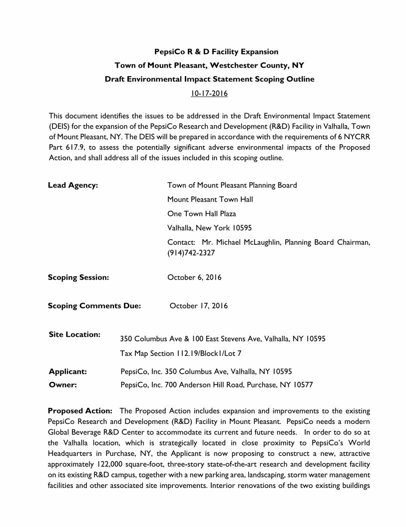
This document identifies the issues to be addressed in the Draft Environmental Impact Statement (DEIS) for the expansion of the PepsiCo Research and Development (R&D) Facility in Valhalla, Town of Mount Pleasant, NY. The DEIS will be prepared in accordance with the requirements of 6 NYCRR Part 617.9, to assess the potentially significant adverse environmental impacts of the Proposed Action, and shall address all of the issues included in this scoping outline.
Lead Agency: Town of Mount Pleasant Planning Board
Mount Pleasant Town Hall
One Town Hall Plaza
Valhalla, New York 10595
Contact: Mr. Michael McLaughlin, Planning Board Chairman, (914)742-2327
Scoping Session: October 6, 2016
Scoping Comments Due: October 17, 2016
Site Location: 350 Columbus Ave & 100 East Stevens Ave, Valhalla, NY 10595
Tax Map Section 112.19/Block1/Lot 7
Applicant: PepsiCo, Inc. 350 Columbus Ave, Valhalla, NY 10595
Owner: PepsiCo, Inc. 700 Anderson Hill Road, Purchase, NY 10577
Proposed Action: The Proposed Action includes expansion and improvements to the existing PepsiCo Research and Development (R&D) Facility in Mount Pleasant. PepsiCo needs a modern Global Beverage R&D Center to accommodate its current and future needs. In order to do so at the Valhalla location, which is strategically located in close proximity to PepsiCo’s World Headquarters in Purchase, NY, the Applicant is now proposing to construct a new, attractive approximately 122,000 square-foot, three-story state-of-the-art research and development facility on its existing R&D campus, together with a new parking area, landscaping, storm water management facilities and other associated site improvements. Interior renovations of the two existing buildings
PepsiCo R&D Expansion - DEIS Scoping Outline 10/17/16
2
on the property (including the expansion of the mezzanine level and a vestibule at 350 Columbus Avenue which will add ±15,000 sf of floor area to the existing building) are also proposed in
connection with the overall modernization of the Property.
CONTENTS OF THE DRAFT ENVIRONMENTAL IMPACT STATEMENT
GENERAL GUIDELINES:
The DEIS will discuss relevant and material facts and evaluate the reasonable alternatives to the Proposed Action identified in this Scoping Outline. It will be clearly and concisely written in language that can be easily read and understood by the public. Highly technical material will be summarized and, if it must be included in its entirety, will be referenced in the DEIS and included as an appendix. In addition, all relevant project correspondence from Involved and Interested Agencies will be included in an appendix to the DEIS.
Narrative discussions will be accompanied to the greatest extent possible by illustrative tables and figures. Each potential impact category (such as land use, traffic, and vegetation, visual) will be the subject of a separate section describing Existing Conditions, Anticipated Impacts, and Proposed Mitigation.
The full DEIS will be made available to the Lead Agency in both hard copy and electronic formats (Adobe Acrobat (.pdf) file). When the DEIS is accepted for public review by the Lead Agency, sufficient hard copies will be provided to allow placement of a copy at the Mount Pleasant library and Town Planning Department for public review during normal business hours. In addition, the full DEIS will be posted on the internet for public review as required by law.
INTRODUCTORY MATERIAL:
A. Cover Sheet. The DEIS shall be preceded by a cover sheet that identifies the following:
• The name, location and tax map designation of the Proposed Action.
• Mount Pleasant Planning Board as the Lead Agency for the project and contact information.
• The name and address of the Applicant, and the name and telephone number of a contact person representing the Applicant.
• The name and address of the primary preparer(s) of the DEIS and the name and telephone number of a contact person representing the preparer(s).
• Date of submission of the DEIS, and date of acceptance of the DEIS [Note: Specific calendar date for acceptance to be inserted].
PepsiCo R&D Expansion - DEIS Scoping Outline 10/17/16
3
• Deadline by which comments on the DEIS are due [Note: Specific calendar date to be inserted].
B. List of Consultants Involved With the Project. The names, addresses and project responsibilities of all consultants involved with the project shall be listed.
C. Table of Contents. All headings which appear in the text shall be presented in the Table of Contents along with the corresponding page numbers. In addition, the Table of Contents shall include a list of exhibits, list of tables, and list of appendix items, with reference to a listing of additional DEIS volumes, if any.
I. EXECUTIVE SUMMARY
The DEIS executive summary shall include the following:
A. Summary description of the Proposed Action, including purpose and need for the project.
B. Brief listing of the anticipated impacts and proposed mitigation measures for each impact issue discussed in the DEIS. The presentation format shall be simple and concise.
C. Brief description of the project alternatives considered in the DEIS.
D. List of Involved and Interested Agencies and required approvals/permits.
II. DESCRIPTION OF PROPOSED ACTION
A. Introduction
The introduction shall include the following:
1. Site location 2. Site acreage, tax map designations and ownership 3. Existing zoning designation 4. Development history of the site, including prior uses.
B. Description of Proposed Action
The detailed description of the Proposed Action shall include the following:
1. Summary of existing site conditions, including existing uses, access, circulation, buildings, parking, recreation facilities and other built improvements.
PepsiCo R&D Expansion - DEIS Scoping Outline 10/17/16
4
2. Summary of natural features on site, including environmental constraints (such as steep slopes, rock outcrops, wetland and wetland buffer areas, etc.). Include brief description of overall drainage areas and relationship to NYCDEP watershed.
3. Summary of Zoning
4. Summary of existing R&D campus, including description of existing circulation,
parking and access; and existing buildings, with operations in each, including labs and research activities. Identify number of employees, hours of operation. Identify frequency of special or non-routine activities that occur at the site. Identify operational issues unique to this R&D facility such as disposal of wastes, chemical hazards, special storage requirements, etc.
5. Description of proposed project components, as shown on the Preliminary Plans, including:
a. Proposed new structures and relationship to existing facility, proposed expansion and new uses. Include areas of new spaces (square footage) and overview of building architecture. Provide preliminary floor plans. b. Access, vehicular circulation, parking and loading, as well as pedestrian circulation and sidewalks. Address pedestrian connections to off-site sidewalks, bus stops and other pedestrian routes. c. Describe green technologies and/or energy efficient aspects of the project. Describe measures and features of Proposed Action that will utilize Green Building Technologies and increase energy efficiency and other measures that address carbon emissions. Describe conservation measures and features that address waste and energy consumption.
6. Summary of proposed improvements to water supply, sanitary sewage, stormwater management and other utilities.
7. Project Purpose, Need and Benefits
a. Description of purpose and need for the expansion project and objectives of the applicant. Identify relationship of this site to the Purchase Headquarters site.
b. Description of the history of this research campus, including the approved Master Plan for Site (1977).
c. Description of benefits of the proposed expansion project, including benefits to the Town.
8. Project Approvals and Reviews
a. Listing of all required approvals and reviews.
PepsiCo R&D Expansion - DEIS Scoping Outline 10/17/16
5
b. Listing of Involved and Interested Agencies.
III. EXISTING ENVIRONMENTAL CONDITIONS, ANTICIPATED IMPACTS AND MITIGATION A. Land Use and Zoning
1. Existing Conditions a. Describe existing land uses and zoning designations on the subject site. b. Describe existing land uses and zoning designations surrounding the site
(within 1/4 mile). c. Describe relevant planning studies, including Westchester 2025, the Mount
Pleasant Comprehensive Plan, Mount Pleasant Hazard Management Plan and Stormwater Plan.
d. Describe PepsiCo’s previous Master Plan for site (1977). 2. Anticipated Impacts
a. Describe potential impacts of the Proposed Action in relation to existing land uses on-site and surrounding land uses (within 1/4 mile of the site).
b. Describe potential impacts of the Proposed Action relative to zoning and compliance with zoning standards, including building setbacks, height, parking and loading, and site coverage standards.
c. Describe compliance with all relevant planning studies (listed above) including the Mount Pleasant Comprehensive Plan, Westchester 2025, and The Bronx River Watershed Management Plan.
d. Describe project relative to 1977 PepsiCo Master Plan. 3. Mitigation Measures
a. Describe site design, layout and configuration as a mitigation measure as well as buffering, if any, to adjacent uses.
B. Geology and Soils
1. Existing Conditions a. Describe regional and site bedrock geology. b. Identify and list soil types on the site, with discussion of soil characteristics
and suitability for construction. Provide a soils map for the site.
2. Anticipated Impacts
a. Provide preliminary grading plan with a limit of disturbance line.
b. Identify and analyze the amount and location of earthwork anticipated (preliminary cut and fill analysis).
c. Describe potential for rock removal including blasting, and potential impacts.
PepsiCo R&D Expansion - DEIS Scoping Outline 10/17/16
6
d. Address archeological impacts of soil disturbance, if any. Consult with State Historic Preservation Office (SHPO) if necessary to determine these impacts.
3. Mitigation Measures
a. Provide a preliminary sediment and erosion control plan.
b. Provide description of components of a rock removal plan, identify if blasting is anticipated, and if so, include how the impacts of blasting would be mitigated.
C. Topography and Slopes
1. Existing Conditions
a. Describe topography on site.
b. Describe existing slopes including categories of 0-15%, 15-25%, and 25% and greater. Provide slope map illustrating these categories.
2. Anticipated Impacts
a. Identify, quantify and map potential impacts to steep slopes (25% and greater) based on the limit of disturbance line.
b. Describe compliance with steep slopes permit standards as per Chapter 180 (Steep Slope Protection) of the Mount Pleasant Town Code.
3. Mitigation Measures
a. Describe site design layout and configuration, erosion and sediment control measures proposed to minimize steep slope impacts, including slope stabilization.
D. Vegetation and Wildlife 1. Existing Conditions
a. Describe existing vegetative communities on the site. b. Provide a survey of trees in the developed portion of the Site (roughly west
of the existing wetland buffer line), as required by Chapter 201, Trees, of the Mount Pleasant Town Code, including specimen trees, protected trees and specimen tree stands. Provide statement of condition of surveyed trees by an Arborist.
c. List any rare, threatened or endangered species on the site (if any). Reference NYSDEC, New York State Natural Heritage Program (NYNHP) and United States Fish and Wildlife Service (USFWS).
2. Anticipated Impacts a. Describe potential impacts to vegetative communities and wildlife habitat.
PepsiCo R&D Expansion - DEIS Scoping Outline 10/17/16
7
b. Describe anticipated tree removal and the Mount Pleasant tree removal permit regulations (Chapter 201, Trees, of the Mount Pleasant Town Code).
c. Describe potential significant adverse impacts to existing wildlife species (if any).
3. Mitigation Measures a. Describe proposed Tree Protection and Reforestation Plan for the site, as
well as other landscaping proposed to mitigate potential impacts including the use of native vegetation to increase habitat values impacted by tree removal and loss of open space as a result of the additional building footprint, parking spaces and other additional impervious surfaces.
b. Describe wildlife mitigation measures, if necessary.
E. Wetlands 1. Existing Conditions
a. Describe and quantify regulated wetland areas or regulated wetland adjacent areas on the site as per Chapter 111, Freshwater Wetlands, of the Mount Pleasant Town Code.
b. Describe National Wetlands Inventory (NWI) wetlands in the project area. 2. Anticipated Impacts
a. Describe and quantify areas in regulated wetlands and adjacent areas to be disturbed based on the limit of disturbance line. Describe potential significant adverse impacts to wetlands.
b. Describe regulated activities and permits required for wetland and/or adjacent area disturbance on the site.
3. Mitigation Measures a. Describe mitigation proposed for wetland impacts, if any.
F. Stormwater Management 1. Existing Conditions
a. Identify and describe existing drainage patterns on the site and within surrounding off-site areas located within the same drainage basin(s) (include map).
b. Calculate and describe the pre-development peak runoff rates for the 1-, 10-, and 100-year storm events.
c. Describe and map Mount Pleasant, NYCDEP, NYSDEC and USACOE regulated existing surface water bodies, intermittent and perennial streams; and 100-year floodplains on the site, and immediately surrounding the site.
d. Identify and describe existing surface water quality conditions on the site. e. Describe existing point and non-point sources of pollution on the site.
2. Anticipated Impacts a. Identify changes in existing drainage patterns and discharge points.
PepsiCo R&D Expansion - DEIS Scoping Outline 10/17/16
8
b. Calculate and describe the post-development peak run-off rates for the 1-, 10- and 100-year storm events.
c. Calculate the total impervious areas for the site. d. Prepare preliminary stormwater quality calculations to satisfy the
requirements of NYCDEP and NYSDEC. e. Identify direct and indirect disturbance to surface waters, watercourses and
100-year floodplain. f. Identify Federal, State and local permits that will be required for any
watercourse impact, including an analysis of the effects of site development on the hydrology of on and off-site wetlands and watercourses.
3. Mitigation Measures a. Include a preliminary Stormwater Pollution Prevention Plan (SWPPP)
which supports the approvals requested. b. Address design layout that considers groundwater recharge through the
use of Low Impact Development (LID) stormwater management systems including landscaping, pervious material, curbing designs and other measures to address on–site infiltration and minimize runoff off-site as outlined in the SPDES General Permit.
G. Utilities 1. Water Supply
a. Existing Conditions • Identify public water supply system in the vicinity of the site including
interconnections with adjacent sites and associated easements. • Identify location of existing water main(s) serving the site and point(s)
of connection. • Identify water supply and available capacity.
b. Anticipated Impacts • Provide average daily water demand for all new potential water uses for
the expansion project, as compared to existing uses. • Evaluate capacity of the water district and describe proposed water
connection. • Determine modifications required to water main connections to
adjacent site and streets from the subject property and associated easements, if required.
• Identify provisions for fire protection. c. Mitigation Measures
2. Sanitary Sewer
a. Existing Conditions
PepsiCo R&D Expansion - DEIS Scoping Outline 10/17/16
9
• Identify existing wastewater treatment facilities to be used and describe its ability to accept additional sanitary waste from the project.
• Identify existing service lines and downstream sewer district mains. b. Anticipated Impacts
• Provide anticipated wastewater generation for the proposed expansion compared to existing uses.
• Describe capacity of the existing sanitary sewer district and describe proposed wastewater treatment connections.
c. Mitigation Measures
3. Other Utilities (Cable Television, Electricity, Natural Gas Internet, Telephone) a. Existing Conditions b. Anticipated Impacts c. Mitigation Measures
H. Traffic and Transportation
1. Existing Conditions
a. Provide a detailed description of roadways in the immediate area, as well as regional access and roadways serving the site. Roadway characteristics will include classifications, general condition, and number and width of lanes by direction, on-street parking, bus stops and traffic control.
b. Existing traffic conditions will be documented for the weekday AM and PM peak hours from historical data and by conducting turning movement manual counts at the following intersections: 1. Columbus Avenue and Town Hall Plaza East/PepsiCo 2. Columbus Avenue and East Stevens Avenue 3. Columbus Avenue and Lozza Drive/ The Summit 4. East Stevens Avenue and Lozza Drive/PepsiCo 5. East Stevens and Lorenz Drive 6. Columbus Avenue and Lakeview Avenue 7. Columbus Avenue and Town Hall Plaza West 8. Columbus Avenue and West Stevens Avenue 9. Columbus Avenue/Kensico Road and Nanny Hagen Road 10. West Stevens Avenue and Commerce Street/Elwood Avenue
Turning movement counts will be collected during typical weekday morning and weekday afternoon peak periods. Data shall not follow or precede holidays and weekday conditions should include dates when schools are in session.
c. Provide Capacity Analysis (Level of Service) for each of the above intersections (SYNCHRO Analysis).
d. Provide parking count for the existing facility on site.
PepsiCo R&D Expansion - DEIS Scoping Outline 10/17/16
10
e. Describe existing pedestrian circulation; both internal to the site and along public roadway frontages (Columbus Avenue and East Stevens Avenue).
2. Anticipated Impacts a. Provide "No Build" Traffic Volumes/Capacity Analysis, including background
traffic growth and other proposed projects in the area (to be provided by the Town) for the build year 2021.
b. Provide "Build" Traffic Volumes/Capacity Analysis, including anticipated trip generation for the Proposed Action. Estimates of site generated traffic will be based on the driveway counts or based on data from similar facilities as well as on information published by the Institute of Transportation Engineers (ITE) as contained in their report entitled Trip Generation, 9th Edition, 2012. Arrival and departure distributions will be developed based upon a review of existing traffic volumes on the roadway network. The Site Generated Traffic Volumes will be assigned to the roadway network based on the anticipated arrival and departure distributions. The Site Generated Traffic Volumes will be combined with the No Build Traffic Volumes to obtain the Build Traffic Volumes for each of the peak hours.
c. Analyze and describe sight distances at both site access driveways. d. Provide a parking analysis for proposed facility and expansion project on site. e. Describe potential impacts to existing pedestrian circulation on the Site.
Investigate feasibility or need for sidewalks along public roadway frontage (Columbus Avenue and East Stevens Avenue).
3. Mitigation Measures a. Where the increased traffic has the potential to significantly affect traffic
operations, the traffic study will identify potential mitigation measures to address such conditions. The discussion of mitigation measures will include the following information:
- The types of roadway improvements, including traffic control; - The party responsible for implementing the improvements and the
method of funding. - Potential pedestrian improvements
I. Visual Resources and Community Character
1. Existing Conditions a. Identify and illustrate existing visual conditions on the site and as viewed from
adjacent streets and properties. Include photographs of existing views toward the site from:
• East Stevens Avenue (Minimum of 2 locations) • Columbus Avenue (Minimum of 2 locations) • The eastern Site property line (closest to Lorenz Drive)
PepsiCo R&D Expansion - DEIS Scoping Outline 10/17/16
11
• The southern Site property line (closest to the Kensico School). 2. Anticipated Impacts
a. Describe anticipated impacts to views to the site from surrounding public roadways and viewpoints. Illustrate proposed conditions as appropriate with visual techniques such as cross sections, perspective views and/or photo simulations.
b. Provide conceptual architectural perspectives for proposed facility expansion and new structure as seen from public roadways.
3. Mitigation Measures
J. Community Facilities and Services 1. Police
a. Existing Conditions • Identify Police Department staff size and organization. • Identify location of police station that services the Site and average
response time. • Describe access to site and discuss adequacy of access. • Identify existing site security measures
b. Anticipated Impacts • Evaluate increased demand for police services. • Analyze the adequacy of emergency access to site.
c. Mitigation Measures
2. Fire and EMS a. Existing Conditions
• Identify which Fire District serves the site and indicate the Fire Department’s staff size, organization, apparatus, and number of calls per year.
• Identify location of fire station (adjacent to Site on Columbus Avenue) and average response time.
• Describe access to site and discuss adequacy of access. • Analyze current water supply and capacity for fire-fighting purposes.
b. Anticipated Impacts • Evaluate increased demand for services. • Analyze the adequacy of access to site. • Identify source of water supply and evaluate pressure and required storage
volumes. • Identify any unique fire safety issues related to the R&D operation.
c. Mitigation Measures
3. Open Space and Recreation
PepsiCo R&D Expansion - DEIS Scoping Outline 10/17/16
12
a. Existing Conditions – Include description of existing community recreation activities on site.
b. Anticipated Impacts c. Mitigation Measures
4. Solid Waste and Hazardous Waste
a. Existing Conditions • Describe how solid waste and hazardous waste are collected and disposed
of in the existing facility. b. Anticipated Impacts
• Describe how solid waste and hazardous waste will be stored, collected and disposed of for the proposed facility expansion.
c. Mitigation Measures • Include information on the storage of any solid and hazardous waste
including fuel oil and any protective measures to be put in place.
K. Fiscal Impacts 1. Existing Conditions
a. Describe existing demographic characteristics of the Town of Mount Pleasant. b. Identify current taxes generated on the site.
2. Anticipated Impacts a. Project additional/new site population that will occupy the site, compared to
existing. b. Provide analysis of property tax revenue to be generated by the Proposed
Action, including an analysis of any PILOT agreement approved by the Mount Pleasant IDA.
c. Describe specifically any tax revenues to be generated by the Proposed Action to the Valhalla School District.
3. Mitigation Measures
L. Air Quality and Noise 1. Existing Conditions – describe air quality and noise conditions at site during
existing operations 2. Anticipated Impacts - describe air quality and noise conditions at site with
Proposed Action 3. Mitigation Measures
M. Construction Impacts
1. Potential Impacts a. Describe proposed demolition, construction phasing and overall schedule for
the facility expansion project.
PepsiCo R&D Expansion - DEIS Scoping Outline 10/17/16
13
b. Identify potential construction traffic, including types of vehicles and route to site.
c. Describe potential temporary impacts to surrounding land uses due to construction activities such as noise, dust or erosion.
d. Describe how new construction will affect existing operations, circulation, parking and employees.
2. Mitigation
IV. ALTERNATIVES For each alternative below (except "No Action") provide a conceptual plan to the level of detail that will enable general comparison to the primary program elements, and general impacts to environmental features, traffic, etc. Provide table which summarizes comparison of Proposed Action to each alternative.
A. No Action (No Build) B. Discuss Alternative Sites C. Alternative Building Location on Site D. Smaller Building on Site
V. OTHER REQUIRED ANALYSES A. Adverse Environmental Impacts Which Cannot be Avoided if the Project is
Implemented B. Irreversible and Irretrievable Commitment of Resources C. Impacts on the Use and Conservation of Energy, including sustainability and green
technology proposed D. Growth Inducing Aspects of Proposed Action. Describe and evaluate any potential that
the Proposed Action may have for triggering further development in terms of attracting similar, additional, or ancillary uses, significant increases in local population, or increasing the demand for support facilities.
E. Cumulative Impacts
VI. APPENDICES A. All SEQRA documentation, including:
a. Environmental Assessment Form (EAF) Part 1 b. Positive Declaration c. Scoping Outline
B. Copies of all official correspondence related to issues discussed in the DEIS, and from Involved and Interested Agencies.
C. Natural Resource Data as available, including: 1. Wetland delineation report 2. Tree survey data
D. Geotechnical data

PepsiCo R&D Expansion - DEIS Scoping Outline 10/17/16
14
E. Stormwater Analysis/Drainage Study (preliminary SWPPP) F. Traffic Impact Study
Attached under separate cover - preliminary engineering plans
f:\2016\16077\seqr\eis scope\pepsi r&d draft deis scope rev10.17.16_redline.docx
APPENDIX B
CORRESPONDENCE
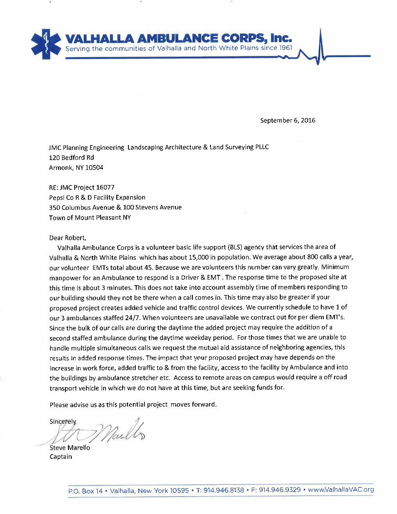
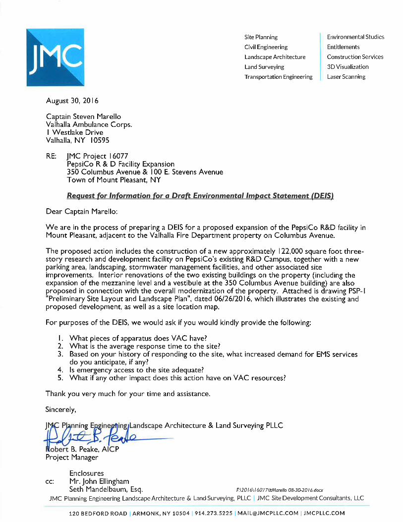

350 COLUMBUS AVE
E STEVENS AVEC
OLU
MBU
S AV
E
W STEVENS AVE
LOZZA DR
TOWNHALLPLZ
LORENZ DR
CO
LUM
BUS
AVE
AERATOR RD
KENSICORESERVOIR
CLO
VEBRO
OK R
D
BRU
CE LN
FOXH
ILL RD
SU
MM
IT LAK
E D
R
HEATH RD
SITE
ZEISS DR
SITE LOCATION
350 COLUMBUS AVE, VALHALLA, NY
SCALE: 1" = 1000'JMC PROJECT: 16077
PEPSICO R&D FACILITY EXPANSION
COPYRIGHT © 2016 by JMC All Rights Reserved. No part of this document may be reproduced, stored in a retrieval system, or transmitted in any form or by means, electronic, mechanical, photocopying, recording or otherwise,without the prior written permission of JMC PLANNING ENGINEERING LANDSCAPE ARCHITECTURE & LAND SURVEYING, PLLC | JMC SITE DEVELOPMENT CONSULTANTS, LLC | JOHN MEYER CONSULTING, INC. (JMC). Anymodifications or alterations to this document without the written permission of JMC shall render them invalid and unusable.
120 BEDFORD RDARMONKNY 10504
(914) 273-5225(FAX) 273-2102
JMCPLLC.COM
SOURCE: USGS
FIGURE: II-1
DATE: XX/XX/XXXX

Drawing No:
Project No:
Date:
Scale:
Drawn: Approved:
ANY ALTERATION OF PLANS,SPECIFICATIONS, PLATS ANDREPORTS BEARING THE SEAL
OF A LICENSED PROFESSIONALENGINEER OR LICENSED LANDSURVEYOR IS A VIOLATION OF
SECTION 7209 OF THE NEWYORK STATE EDUCATION LAW,EXCEPT AS PROVIDED FOR BYSECTION 7209, SUBSECTION 2.
OWNE
R:
APPL
ICAN
T:
No.
Revis
ionDa
te
Prev
ious E
dition
s Obs
olete
By
COPY
RIGH
T ©
2016
by JM
C Al
l Righ
ts Re
serve
d. N
o par
t of th
is do
cume
nt ma
y be r
epro
duce
d, sto
red i
n a re
trieva
l sys
tem, o
r tra
nsmi
tted i
n any
form
or by
mea
ns, e
lectro
nic, m
echa
nical,
photo
copy
ing, r
ecor
ding o
r othe
rwise
, with
out th
e prio
r writt
en pe
rmiss
ion of
JMC
PLAN
NING
, ENG
INEE
RING
, LAN
DSCA
PE A
RCHI
TECT
URE
& LA
ND S
URVE
YING
, PLL
C | J
MC S
ITE
DEVE
LOPM
ENT
CONS
ULTA
NTS,
LLC
| JOH
N ME
YER
CONS
ULTI
NG, IN
C. (J
MC).
Any
mod
ificati
ons o
r alte
ratio
ns to
this
docu
ment
witho
ut the
writt
en pe
rmiss
ion of
JMC
shall
rend
er th
em in
valid
and u
nusa
ble.
PROPOSED R+D BUILDING
O
O
O
O
O
OO
O
O
O
O
OO
O
O
O
O
O O
O
O O
OOO
OO O
O
O
OO
O
OO
O
O
OO
OO
O
O
OO
O
O
O
O
O
O
O
O
O
O
O
O
O
O
O
OOO
OOO
O
OO
O
OO
OO
O
O
O O
O
O
O
O
O
OO
OO
O
O
O
O
OO
O
O
O
O
O
O
O
O
O
O
O
O
O
O
EXISTING BUILDING 350
EXISTIN
G BUILDIN
G 100
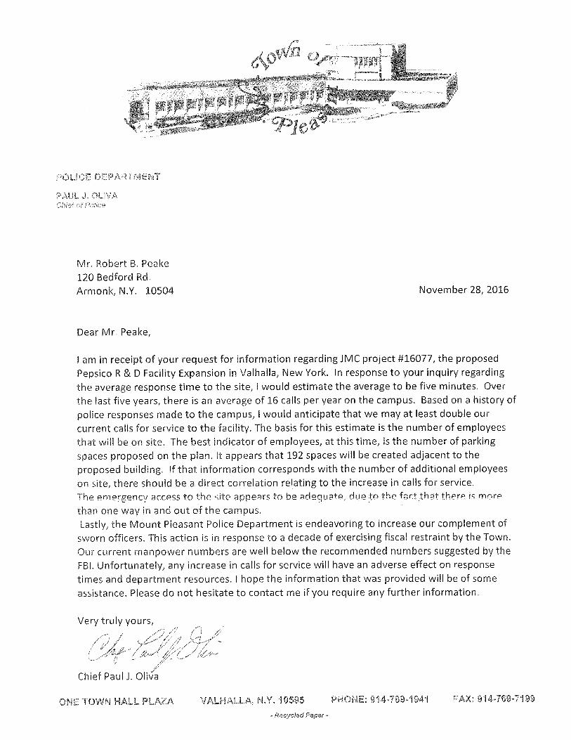
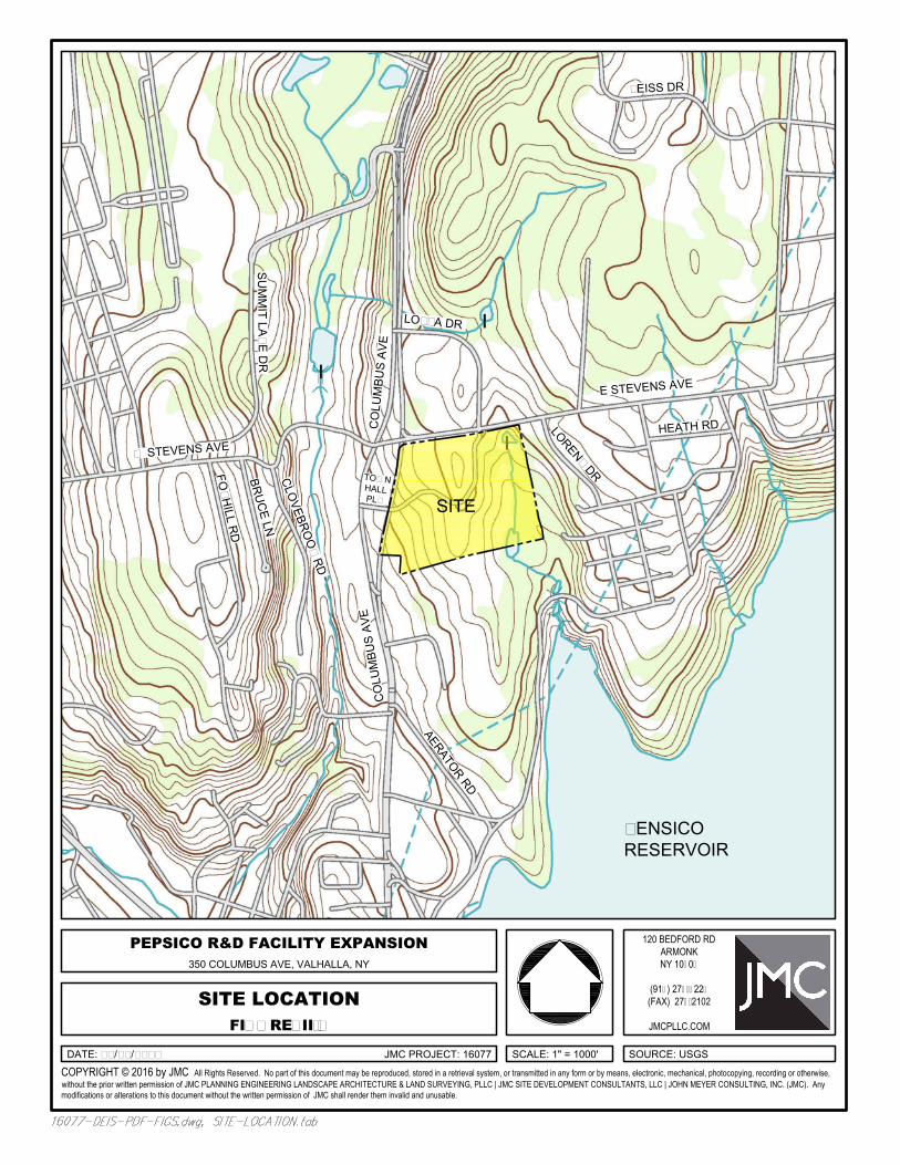
350 COLUMBUS AVE
E STEVENS AVEC
OLU
MBU
S AV
E
W STEVENS AVE
LOZZA DR
TOWNHALLPLZ
LORENZ DR
CO
LUM
BUS
AVE
AERATOR RD
KENSICORESERVOIR
CLO
VEBRO
OK R
D
BRU
CE LN
FOXH
ILL RD
SU
MM
IT LAK
E D
R
HEATH RD
SITE
ZEISS DR
SITE LOCATION
350 COLUMBUS AVE, VALHALLA, NY
SCALE: 1" = 1000'JMC PROJECT: 16077
PEPSICO R&D FACILITY EXPANSION
COPYRIGHT © 2016 by JMC All Rights Reserved. No part of this document may be reproduced, stored in a retrieval system, or transmitted in any form or by means, electronic, mechanical, photocopying, recording or otherwise,without the prior written permission of JMC PLANNING ENGINEERING LANDSCAPE ARCHITECTURE & LAND SURVEYING, PLLC | JMC SITE DEVELOPMENT CONSULTANTS, LLC | JOHN MEYER CONSULTING, INC. (JMC). Anymodifications or alterations to this document without the written permission of JMC shall render them invalid and unusable.
120 BEDFORD RDARMONKNY 10504
(914) 273-5225(FAX) 273-2102
JMCPLLC.COM
SOURCE: USGS
FIGURE: II-1
DATE: XX/XX/XXXX
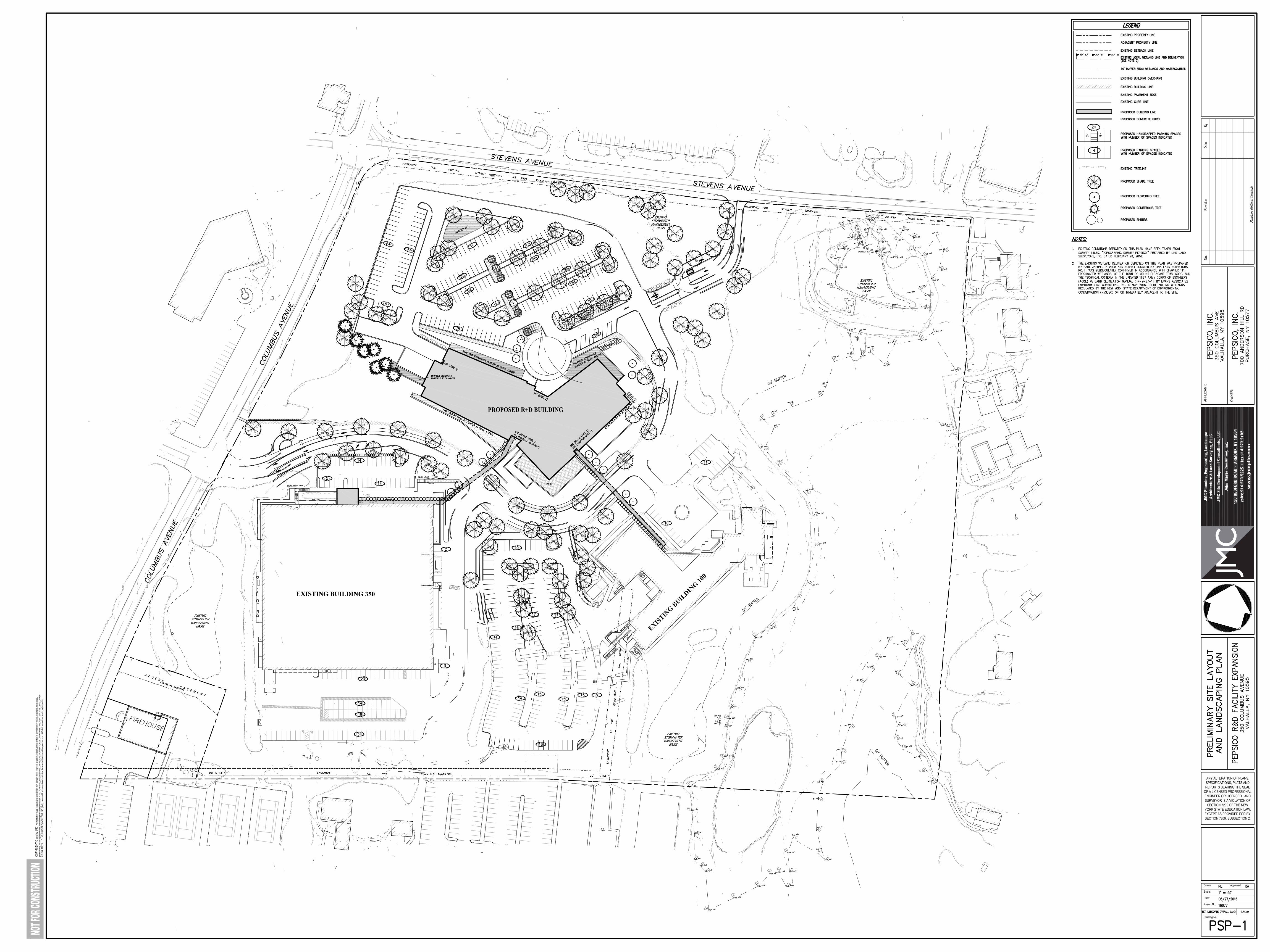
Drawing No:
Project No:
Date:
Scale:
Drawn: Approved:
ANY ALTERATION OF PLANS,SPECIFICATIONS, PLATS ANDREPORTS BEARING THE SEAL
OF A LICENSED PROFESSIONALENGINEER OR LICENSED LANDSURVEYOR IS A VIOLATION OF
SECTION 7209 OF THE NEWYORK STATE EDUCATION LAW,EXCEPT AS PROVIDED FOR BYSECTION 7209, SUBSECTION 2.
OWNE
R:
APPL
ICAN
T:
No.
Revis
ionDa
te
Prev
ious E
dition
s Obs
olete
By
COPY
RIGH
T ©
2016
by JM
C Al
l Righ
ts Re
serve
d. N
o par
t of th
is do
cume
nt ma
y be r
epro
duce
d, sto
red i
n a re
trieva
l sys
tem, o
r tra
nsmi
tted i
n any
form
or by
mea
ns, e
lectro
nic, m
echa
nical,
photo
copy
ing, r
ecor
ding o
r othe
rwise
, with
out th
e prio
r writt
en pe
rmiss
ion of
JMC
PLAN
NING
, ENG
INEE
RING
, LAN
DSCA
PE A
RCHI
TECT
URE
& LA
ND S
URVE
YING
, PLL
C | J
MC S
ITE
DEVE
LOPM
ENT
CONS
ULTA
NTS,
LLC
| JOH
N ME
YER
CONS
ULTI
NG, IN
C. (J
MC).
Any
mod
ificati
ons o
r alte
ratio
ns to
this
docu
ment
witho
ut the
writt
en pe
rmiss
ion of
JMC
shall
rend
er th
em in
valid
and u
nusa
ble.
PROPOSED R+D BUILDING
O
O
O
O
O
OO
O
O
O
O
OO
O
O
O
O
O O
O
O O
OOO
OO O
O
O
OO
O
OO
O
O
OO
OO
O
O
OO
O
O
O
O
O
O
O
O
O
O
O
O
O
O
O
OOO
OOO
O
OO
O
OO
OO
O
O
O O
O
O
O
O
O
OO
OO
O
O
O
O
OO
O
O
O
O
O
O
O
O
O
O
O
O
O
O
EXISTING BUILDING 350
EXISTIN
G BUILDIN
G 100
APPENDIX C
GEOTECHNICAL DATA
1. Carlin-Simpson & Associates preliminary
memorandum, dated June 23, 2015
2. Carlin-Simpson & Associates supplemental
memorandum, dated November 23, 2015
CARLIN • SIMPSON & ASSOCIATES Consulting Engineers
Geotechnical & Environmental
MEMO DATE: 23 June 2015 TO: Mr. Rob Aiello, P.E. FROM: Robert B. Simpson, P.E. JMC Robert H. Barnes P.E. RE: Project Eden JOB NO: 15-37 Pepsi – Valhalla Campus Valhalla, New York We understand that the planned construction will consist of a new four level research/office building. The following is a summary of the preliminary geotechnical design recommendations for the referenced project. During this study, fourteen (14) test borings were performed at the subject site at the locations shown on the attached Boring Location Plan. The boring data is summarized in the following table.
Preliminary Boring Data Boring No. Approximate
Ground Surface
Elevation (Feet)
Depth to Bottom of Existing Fill (Elevation)
Depth to Completely Weathered
Schist (Elevation)
Depth to Auger Refusal of Cored
Schist (Elevation)
B-1 +459.0 1.5’ (+457.5) NE 8.0’ (+451.0) B-2 +452.5 6.0’(+446.5) 6.0’(+446.5) 8.5’ (+444.0) B-3 +447.5 3.0’ (+444.5) 10.0’ (+437.5) 13.0’ (+434.5) B-4 +453.5 NE 3.0’ (+450.5) 10.3’ (+443.2) B-5 +449.5 NE NE 23.0’ (+426.5) B-6 +466.0 NE 3.0’ (+463.0) NE (<+460.3) B-7 +462.0 NE 2.5’ (+459.5) 8.0’ (+454.0) B-8 +451.5 4.5’ (+447.0) 16.5’ (+435.0) 23.0’ (+428.5) B-9 +450.0 4.5’ (+445.5) NE NE (<+428.0) B-10 +448.0 9.5’ (+438.5) NE NE (<+421.0) B-11 +462.0 2.5’ (+459.5) 10.5’ (+451.5) 11.0’ (+451.0) B-12 +433.5 NE 15.5’ (+418.0) NE (<+423.0) B-13 +448.5 NE NE 3.2’ (+445.3) B-14 +449.5 NE NE 2.5’ (+447.0)
NE – Not encountered in boring.
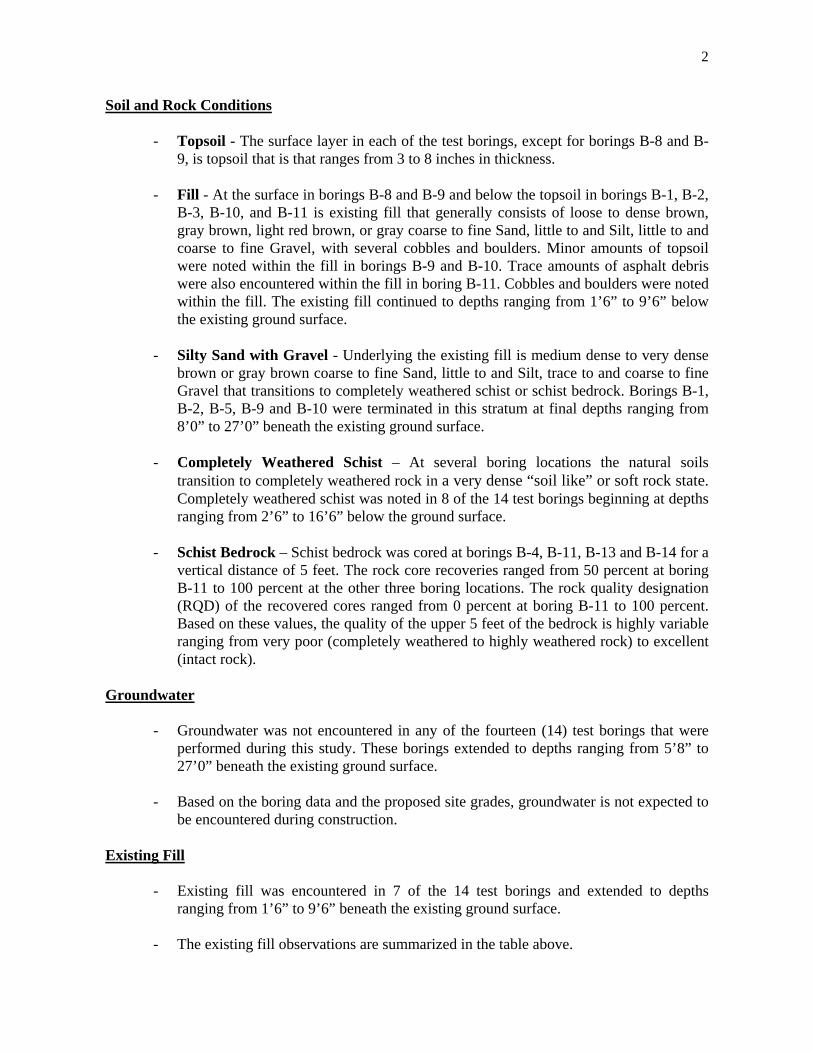
2
Soil and Rock Conditions
- Topsoil - The surface layer in each of the test borings, except for borings B-8 and B-9, is topsoil that is that ranges from 3 to 8 inches in thickness.
- Fill - At the surface in borings B-8 and B-9 and below the topsoil in borings B-1, B-2,
B-3, B-10, and B-11 is existing fill that generally consists of loose to dense brown, gray brown, light red brown, or gray coarse to fine Sand, little to and Silt, little to and coarse to fine Gravel, with several cobbles and boulders. Minor amounts of topsoil were noted within the fill in borings B-9 and B-10. Trace amounts of asphalt debris were also encountered within the fill in boring B-11. Cobbles and boulders were noted within the fill. The existing fill continued to depths ranging from 1’6” to 9’6” below the existing ground surface.
- Silty Sand with Gravel - Underlying the existing fill is medium dense to very dense
brown or gray brown coarse to fine Sand, little to and Silt, trace to and coarse to fine Gravel that transitions to completely weathered schist or schist bedrock. Borings B-1, B-2, B-5, B-9 and B-10 were terminated in this stratum at final depths ranging from 8’0” to 27’0” beneath the existing ground surface.
- Completely Weathered Schist – At several boring locations the natural soils
transition to completely weathered rock in a very dense “soil like” or soft rock state. Completely weathered schist was noted in 8 of the 14 test borings beginning at depths ranging from 2’6” to 16’6” below the ground surface.
- Schist Bedrock – Schist bedrock was cored at borings B-4, B-11, B-13 and B-14 for a
vertical distance of 5 feet. The rock core recoveries ranged from 50 percent at boring B-11 to 100 percent at the other three boring locations. The rock quality designation (RQD) of the recovered cores ranged from 0 percent at boring B-11 to 100 percent. Based on these values, the quality of the upper 5 feet of the bedrock is highly variable ranging from very poor (completely weathered to highly weathered rock) to excellent (intact rock).
Groundwater
- Groundwater was not encountered in any of the fourteen (14) test borings that were performed during this study. These borings extended to depths ranging from 5’8” to 27’0” beneath the existing ground surface.
- Based on the boring data and the proposed site grades, groundwater is not expected to
be encountered during construction. Existing Fill
- Existing fill was encountered in 7 of the 14 test borings and extended to depths ranging from 1’6” to 9’6” beneath the existing ground surface.
- The existing fill observations are summarized in the table above.
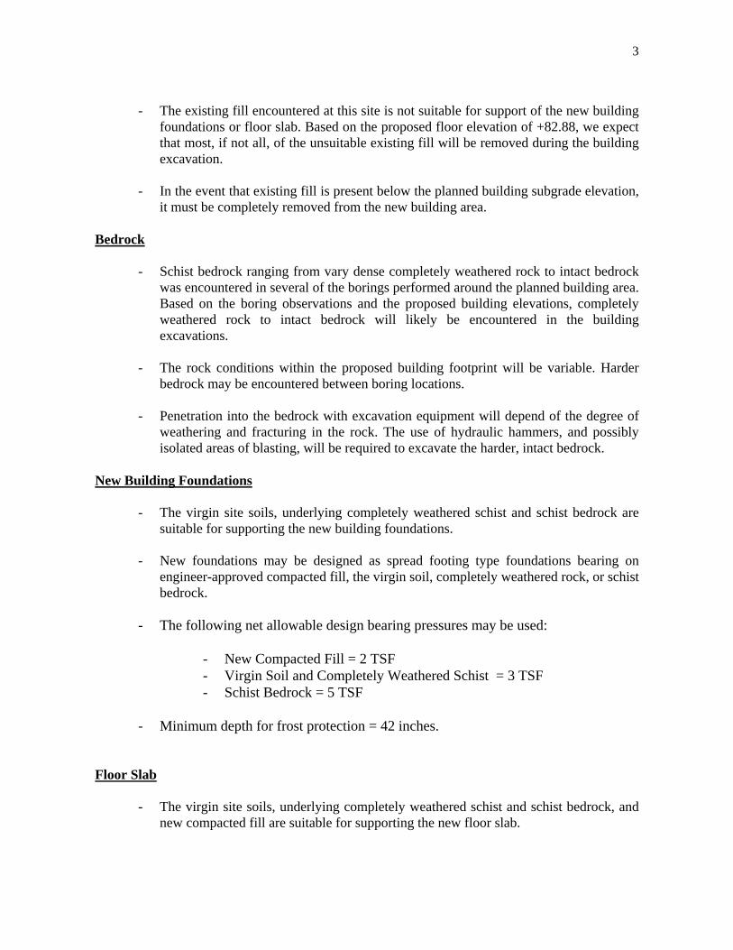
3
- The existing fill encountered at this site is not suitable for support of the new building
foundations or floor slab. Based on the proposed floor elevation of +82.88, we expect that most, if not all, of the unsuitable existing fill will be removed during the building excavation.
- In the event that existing fill is present below the planned building subgrade elevation,
it must be completely removed from the new building area. Bedrock
- Schist bedrock ranging from vary dense completely weathered rock to intact bedrock was encountered in several of the borings performed around the planned building area. Based on the boring observations and the proposed building elevations, completely weathered rock to intact bedrock will likely be encountered in the building excavations.
- The rock conditions within the proposed building footprint will be variable. Harder
bedrock may be encountered between boring locations.
- Penetration into the bedrock with excavation equipment will depend of the degree of weathering and fracturing in the rock. The use of hydraulic hammers, and possibly isolated areas of blasting, will be required to excavate the harder, intact bedrock.
New Building Foundations
- The virgin site soils, underlying completely weathered schist and schist bedrock are suitable for supporting the new building foundations.
- New foundations may be designed as spread footing type foundations bearing on
engineer-approved compacted fill, the virgin soil, completely weathered rock, or schist bedrock.
- The following net allowable design bearing pressures may be used:
- New Compacted Fill = 2 TSF - Virgin Soil and Completely Weathered Schist = 3 TSF - Schist Bedrock = 5 TSF
- Minimum depth for frost protection = 42 inches.
Floor Slab
- The virgin site soils, underlying completely weathered schist and schist bedrock, and new compacted fill are suitable for supporting the new floor slab.
4
- The floor slab may be designed as a slab on grade using a Modulus of Subgrade Reaction = 200 pci.
Foundation Wall Design Parameters
- The soil adjacent to the foundation walls will exert a horizontal pressure against the walls. This pressure is based on the soil density and the coefficient of earth pressure at rest (ko) which is applicable to non-yielding foundation walls. We estimate the backfill material will have an in-place density of about 135 pcf and a ko of 0.47. These assumptions result in an equivalent fluid pressure of 63.5 psf/ft against the walls.
- For design, the following values may be used:
a. Angle of internal friction (phi) = 32 degrees b. Coefficient of Earth Pressure at Rest, ko = 0.47 c. Coefficient of Passive Pressure, kp = 3.26 d. Soil/concrete friction factor = 0.45
Site Retaining Wall Design Parameters
a. Angle of internal friction (phi) φ = 32o b. In-place density, γ = 135 pcf c. Coefficient of Active Pressure, Ka = 0.307 d. Equivalent fluid pressure. = 41.5 psf/ft e. Soil/concrete friction factor = 0.45
- The existing fill encountered at this site is not suitable for support of the new retaining
wall in its current state. The retaining wall area shall be excavated to the planned subgrade elevation and the remaining existing fill shall be densified in place under the full-time inspection of Carlin-Simpson & Associates. In the event that soft or unsuitable existing fill is identified during the densification, the unsuitable material shall be removed and replaced with new compacted fill.
- Retaining wall base or footing shall bear on virgin site soils, densified existing fill, or
on Engineer-approved compacted fill.
- Net design bearing pressure = 2.0 TSF
- Minimum depth for frost protection = 42 inches.
- Drain pipes and drainage stone fill must be provided behind the wall for drainage. Seismic
- The new building shall be designed to resist stress produced by lateral forces computed in accordance with the New York State Building Code. The project site can be classified as Site Class C – Very Dense Soil and Soft Rock Profile.
5
Suitability of Site Soils for Use as Compacted Fill
- The existing site soils may be reused as compacted fill provided the soil is free of debris and organic material (i.e. roots, topsoil, etc.) and has not become too wet for proper compaction.
- Topsoil is not suitable for use as compacted fill.
- The silty site soils are sensitive to moisture. Proper moisture conditioning of the site
soils will be required. In the event that the on-site material is too wet at the time of placement and cannot be adequately compacted, the soil should be aerated and allowed to dry or the material removed and a drier fill material used.
- We recommend that adequate site drainage be implemented early in the construction
schedule and if the subgrade becomes wet, the contractor should limit construction activity until the soil has dried.
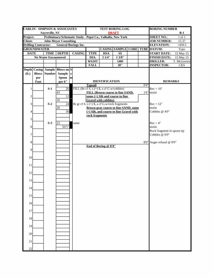
CARLIN - SIMPSON & ASSOCIATES TEST BORING LOG BORING NUMBERSayreville, NJ B-1
Project: Preliminary/Schematic Study - Pepsi Co., Valhalla, New York SHEET NO.: 1 of 1Client: John Meyer Consulting JOB NUMBER: 15-37Drilling Contractor: General Borings Inc. ELEVATION: +459.5GROUNDWATER CASING SAMPLE CORE TUBE DATUM: Topo DATE TIME DEPTH CASING TYPE HSA SS START DATE: 15 May 15
No Water Encountered DIA. 3 1/4" 1 3/8" FINISH DATE: 15 May 15WGHT 140# DRILLER: T. McGovernFALL 30" INSPECTOR: CKS
Depth (ft.)
Casing Blows
per Foot
Sample Number
Blows on Sample Spoon per 6" IDENTIFICATION REMARKS
5 Topsoil 0'4"1 S-1 26 FILL (Br cf S, s (+) $, a cf G w/cobbles) Rec = 10"
43 FILL (Brown coarse to fine SAND, 1'6" moist2 12 some (+) Silt and coarse to fine
10 Gravel with cobbles)3 S-2 24 Br gr cf S, s (+) $, a cf G,w/rock fragments Rec = 12"
28 Brown gray coarse to fine SAND, some moist4 56 (+) Silt, and coarse to fine Gravel with Cobbles @ 4'0"
rock fragments5
S-3 23 same Rec = 4"6 50/5" moist
Rock fragment in spoon tip7 Cobbles @ 6'0"
8 8'0" Auger refusal @ 8'0"End of Boring @ 8'0"
9
10
11
12
13
14
15
16
17
18
19
20
21
22
Sym
DRAFT
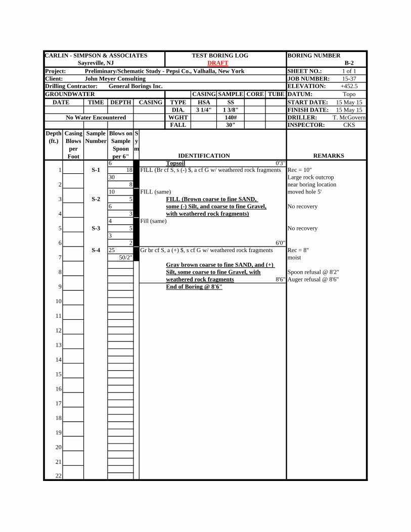
CARLIN - SIMPSON & ASSOCIATES TEST BORING LOG BORING NUMBERSayreville, NJ B-2
Project: Preliminary/Schematic Study - Pepsi Co., Valhalla, New York SHEET NO.: 1 of 1Client: John Meyer Consulting JOB NUMBER: 15-37Drilling Contractor: General Borings Inc. ELEVATION: +452.5GROUNDWATER CASING SAMPLE CORE TUBE DATUM: Topo DATE TIME DEPTH CASING TYPE HSA SS START DATE: 15 May 15
DIA. 3 1/4" 1 3/8" FINISH DATE: 15 May 15No Water Encountered WGHT 140# DRILLER: T. McGovern
FALL 30" INSPECTOR: CKSDepth
(ft.)Casing Blows
per Foot
Sample Number
Blows on Sample Spoon per 6" IDENTIFICATION REMARKS
6 Topsoil 0'3"1 S-1 18 FILL (Br cf S, s (-) $, a cf G w/ weathered rock fragments Rec = 10"
30 Large rock outcrop 2 8 near boring location
10 FILL (same) moved hole 5'3 S-2 5 FILL (Brown coarse to fine SAND,
6 some (-) Silt, and coarse to fine Gravel, No recovery4 3 with weathered rock fragments)
4 Fill (same)5 S-3 5 No recovery
36 2 6'0"
S-4 25 Gr br cf S, a (+) $, s cf G w/ weathered rock fragments Rec = 8"7 50/2" moist
Gray brown coarse to fine SAND, and (+) 8 Silt, some coarse to fine Gravel, with Spoon refusal @ 8'2"
weathered rock fragments 8'6" Auger refusal @ 8'6"9 End of Boring @ 8'6"
10
11
12
13
14
15
16
17
18
19
20
21
22
Sym
DRAFT
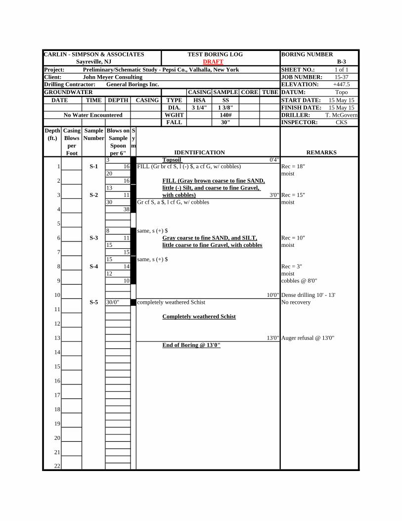
CARLIN - SIMPSON & ASSOCIATES TEST BORING LOG BORING NUMBERSayreville, NJ B-3
Project: Preliminary/Schematic Study - Pepsi Co., Valhalla, New York SHEET NO.: 1 of 1Client: John Meyer Consulting JOB NUMBER: 15-37Drilling Contractor: General Borings Inc. ELEVATION: +447.5GROUNDWATER CASING SAMPLE CORE TUBE DATUM: Topo DATE TIME DEPTH CASING TYPE HSA SS START DATE: 15 May 15
DIA. 3 1/4" 1 3/8" FINISH DATE: 15 May 15No Water Encountered WGHT 140# DRILLER: T. McGovern
FALL 30" INSPECTOR: CKSDepth
(ft.)Casing Blows
per Foot
Sample Number
Blows on Sample Spoon per 6" IDENTIFICATION REMARKS
3 Topsoil 0'4"1 S-1 16 FILL (Gr br cf S, l (-) $, a cf G, w/ cobbles) Rec = 18"
20 moist2 16 FILL (Gray brown coarse to fine SAND,
13 little (-) Silt, and coarse to fine Gravel, 3 S-2 11 with cobbles) 3'0" Rec = 15"
30 Gr cf S, a $, l cf G, w/ cobbles moist4 38
58 same, s (+) $
6 S-3 11 Gray coarse to fine SAND, and SILT, Rec = 10"15 little coarse to fine Gravel, with cobbles moist
7 1515 same, s (+) $
8 S-4 14 Rec = 3"12 moist
9 10 cobbles @ 8'0"
10 10'0" Dense drilling 10' - 13'S-5 30/0" completely weathered Schist No recovery
11Completely weathered Schist
12
13 13'0" Auger refusal @ 13'0"End of Boring @ 13'0"
14
15
16
17
18
19
20
21
22
Sym
DRAFT
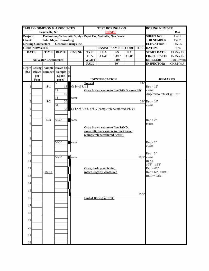
CARLIN - SIMPSON & ASSOCIATES TEST BORING LOG BORING NUMBERSayreville, NJ B-4
Project: Preliminary/Schematic Study - Pepsi Co., Valhalla, New York SHEET NO.: 1 of 1Client: John Meyer Consulting JOB NUMBER: 15-37Drilling Contractor: General Borings Inc. ELEVATION: +453.5GROUNDWATER CASING SAMPLE CORE TUBE DATUM: Topo DATE TIME DEPTH CASING TYPE HSA SS NX START DATE: 13 May 15
DIA. 3 1/4" 1 3/8" 3 3/8" FINISH DATE: 15 May 15No Water Encountered WGHT 140# DRILLER: T. McGovern
FALL 30" INSPECTOR: CKS/KWADepth
(ft.)Casing Blows
per Foot
Sample Number
Blows on Sample Spoon per 6" IDENTIFICATION REMARKS
5 Topsoil 0'6"1 S-1 13 Gr br cf S, s $ Rec = 12"
17 Gray brown coarse to fine SAND, some Silt moist2 16 Augered to refusal @ 10'0"
11 same3 S-2 20 3'0" Rec = 14"
34 moist4 38 Gr br cf S, s $, t cf G (completely weathered schist)
5S-3 50/4" same Rec = 2"
6 moistGray brown coarse to fine SAND,
7 some Silt, trace coarse to fine Gravel(completely weathered Schist)
850/3" same Rec = 2"
9 moist
10 Rec = 3"50/3" same 10'3" moist
11 Run 110'3" - 15'3"
12 Gray, dark gray Schist, Run = 60"Run 1 intact, slightly weathered Rec = 60", 100%
13 RQD = 93%
14
1515'3"
16 End of Boring @ 15'3"
17
18
19
20
21
22
Sym
DRAFT
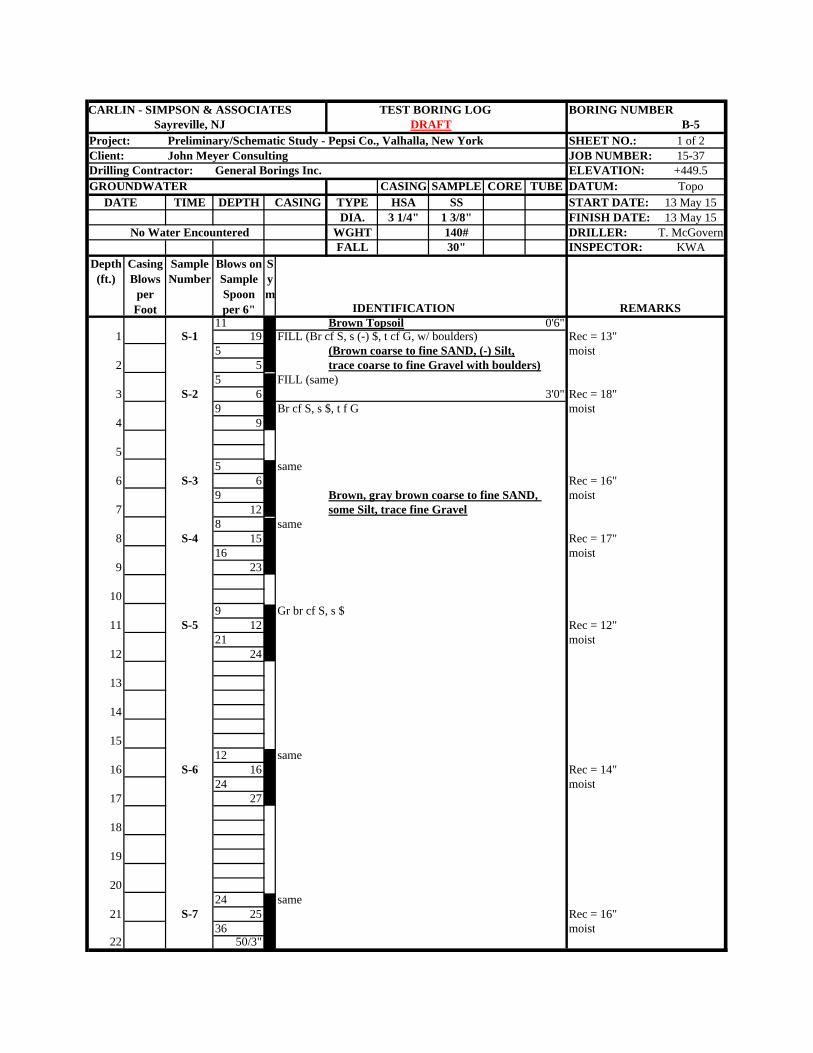
CARLIN - SIMPSON & ASSOCIATES TEST BORING LOG BORING NUMBERSayreville, NJ B-5
Project: Preliminary/Schematic Study - Pepsi Co., Valhalla, New York SHEET NO.: 1 of 2Client: John Meyer Consulting JOB NUMBER: 15-37Drilling Contractor: General Borings Inc. ELEVATION: +449.5GROUNDWATER CASING SAMPLE CORE TUBE DATUM: Topo DATE TIME DEPTH CASING TYPE HSA SS START DATE: 13 May 15
DIA. 3 1/4" 1 3/8" FINISH DATE: 13 May 15No Water Encountered WGHT 140# DRILLER: T. McGovern
FALL 30" INSPECTOR: KWADepth
(ft.)Casing Blows
per Foot
Sample Number
Blows on Sample Spoon per 6" IDENTIFICATION REMARKS
11 Brown Topsoil 0'6"1 S-1 19 FILL (Br cf S, s (-) $, t cf G, w/ boulders) Rec = 13"
5 (Brown coarse to fine SAND, (-) Silt, moist2 5 trace coarse to fine Gravel with boulders)
5 FILL (same)3 S-2 6 3'0" Rec = 18"
9 Br cf S, s $, t f G moist4 9
55 same
6 S-3 6 Rec = 16"9 Brown, gray brown coarse to fine SAND, moist
7 12 some Silt, trace fine Gravel8 same
8 S-4 15 Rec = 17"16 moist
9 23
109 Gr br cf S, s $
11 S-5 12 Rec = 12"21 moist
12 24
13
14
1512 same
16 S-6 16 Rec = 14"24 moist
17 27
18
19
2024 same
21 S-7 25 Rec = 16"36 moist
22 50/3"
Sym
DRAFT
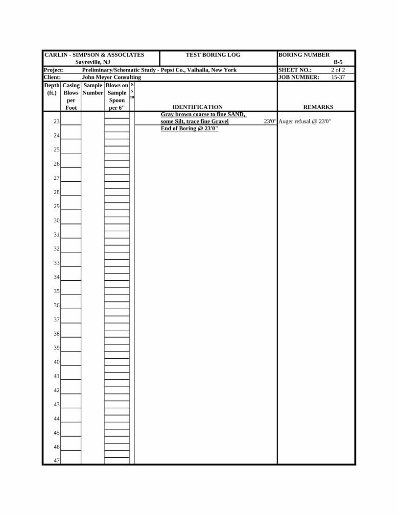
CARLIN - SIMPSON & ASSOCIATES TEST BORING LOG BORING NUMBERSayreville, NJ B-5
Project: Preliminary/Schematic Study - Pepsi Co., Valhalla, New York SHEET NO.: 2 of 2Client: John Meyer Consulting JOB NUMBER: 15-37Depth
(ft.)Casing Blows
per Foot
Sample Number
Blows on Sample Spoon per 6" IDENTIFICATION REMARKS
Gray brown coarse to fine SAND, 23 some Silt, trace fine Gravel 23'0" Auger refusal @ 23'0"
End of Boring @ 23'0"24
25
26
27
28
29
30
31
32
33
34
35
36
37
38
39
40
41
42
43
44
45
46
47
Sym
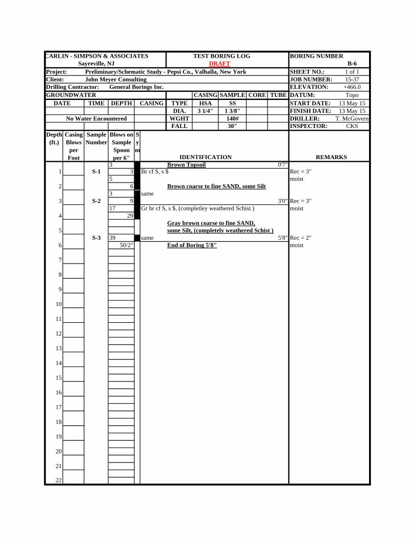
CARLIN - SIMPSON & ASSOCIATES TEST BORING LOG BORING NUMBERSayreville, NJ B-6
Project: Preliminary/Schematic Study - Pepsi Co., Valhalla, New York SHEET NO.: 1 of 1Client: John Meyer Consulting JOB NUMBER: 15-37Drilling Contractor: General Borings Inc. ELEVATION: +466.0GROUNDWATER CASING SAMPLE CORE TUBE DATUM: Topo DATE TIME DEPTH CASING TYPE HSA SS START DATE: 13 May 15
DIA. 3 1/4" 1 3/8" FINISH DATE: 13 May 15No Water Encountered WGHT 140# DRILLER: T. McGovern
FALL 30" INSPECTOR: CKSDepth
(ft.)Casing Blows
per Foot
Sample Number
Blows on Sample Spoon per 6" IDENTIFICATION REMARKS
3 Brown Topsoil 0'7"1 S-1 3 Br cf S, s $ Rec = 3"
5 moist2 6 Brown coarse to fine SAND, some Silt
3 same3 S-2 9 3'0" Rec = 3"
17 Gr br cf S, s $, (completley weathered Schist ) moist4 29
Gray brown coarse to fine SAND,5 some Silt, (completely weathered Schist )
S-3 39 same 5'8" Rec = 2"6 50/2" End of Boring 5'8" moist
7
8
9
10
11
12
13
14
15
16
17
18
19
20
21
22
Sym
DRAFT
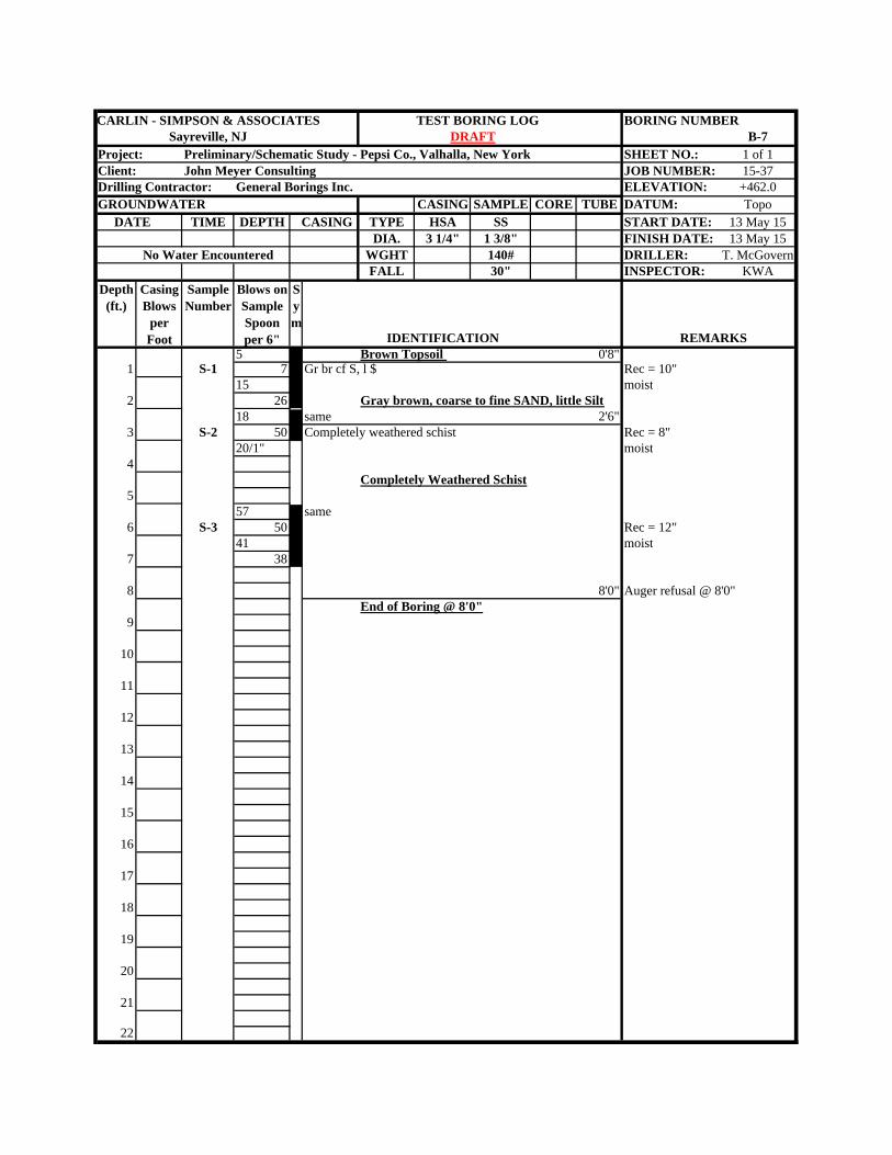
CARLIN - SIMPSON & ASSOCIATES TEST BORING LOG BORING NUMBERSayreville, NJ B-7
Project: Preliminary/Schematic Study - Pepsi Co., Valhalla, New York SHEET NO.: 1 of 1Client: John Meyer Consulting JOB NUMBER: 15-37Drilling Contractor: General Borings Inc. ELEVATION: +462.0GROUNDWATER CASING SAMPLE CORE TUBE DATUM: Topo DATE TIME DEPTH CASING TYPE HSA SS START DATE: 13 May 15
DIA. 3 1/4" 1 3/8" FINISH DATE: 13 May 15No Water Encountered WGHT 140# DRILLER: T. McGovern
FALL 30" INSPECTOR: KWADepth
(ft.)Casing Blows
per Foot
Sample Number
Blows on Sample Spoon per 6" IDENTIFICATION REMARKS
5 Brown Topsoil 0'8"1 S-1 7 Gr br cf S, l $ Rec = 10"
15 moist2 26 Gray brown, coarse to fine SAND, little Silt
18 same 2'6"3 S-2 50 Completely weathered schist Rec = 8"
20/1" moist4
Completely Weathered Schist5
57 same6 S-3 50 Rec = 12"
41 moist7 38
8 8'0" Auger refusal @ 8'0"End of Boring @ 8'0"
9
10
11
12
13
14
15
16
17
18
19
20
21
22
Sym
DRAFT
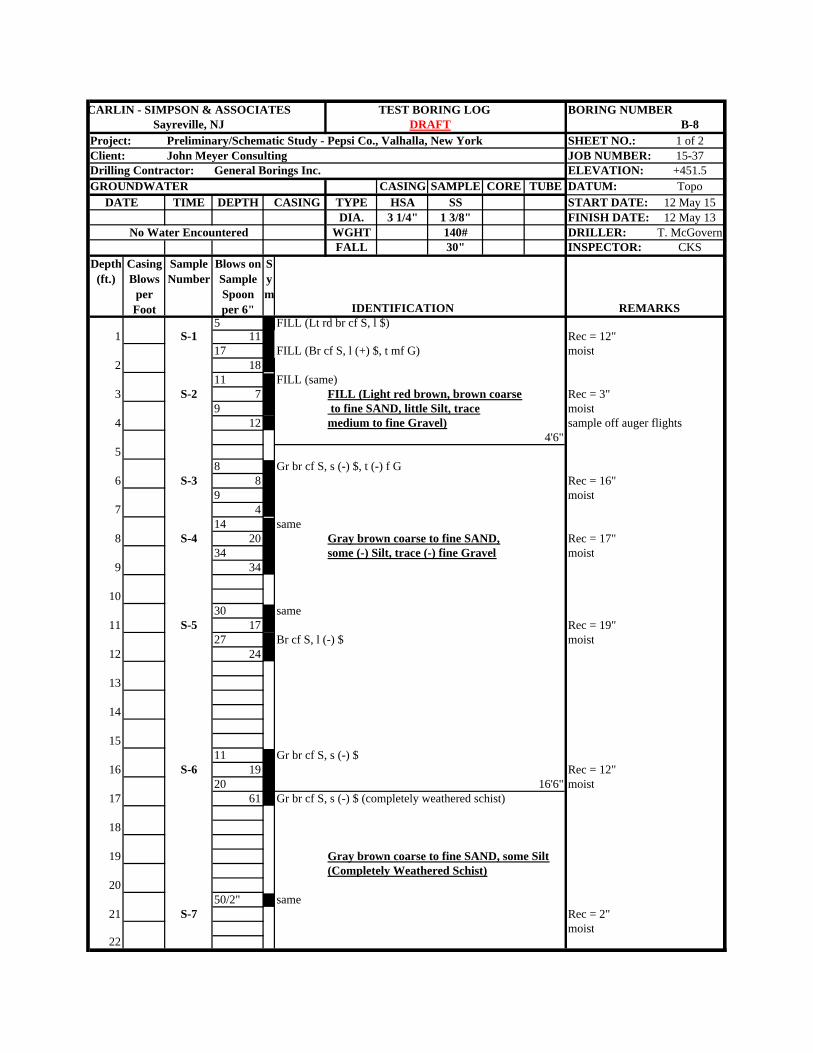
CARLIN - SIMPSON & ASSOCIATES TEST BORING LOG BORING NUMBERSayreville, NJ B-8
Project: Preliminary/Schematic Study - Pepsi Co., Valhalla, New York SHEET NO.: 1 of 2Client: John Meyer Consulting JOB NUMBER: 15-37Drilling Contractor: General Borings Inc. ELEVATION: +451.5GROUNDWATER CASING SAMPLE CORE TUBE DATUM: Topo DATE TIME DEPTH CASING TYPE HSA SS START DATE: 12 May 15
DIA. 3 1/4" 1 3/8" FINISH DATE: 12 May 13No Water Encountered WGHT 140# DRILLER: T. McGovern
FALL 30" INSPECTOR: CKSDepth
(ft.)Casing Blows
per Foot
Sample Number
Blows on Sample Spoon per 6" IDENTIFICATION REMARKS
5 FILL (Lt rd br cf S, l $)1 S-1 11 Rec = 12"
17 FILL (Br cf S, l (+) $, t mf G) moist2 18
11 FILL (same)3 S-2 7 FILL (Light red brown, brown coarse Rec = 3"
9 to fine SAND, little Silt, trace moist4 12 medium to fine Gravel) sample off auger flights
4'6"5
8 Gr br cf S, s (-) $, t (-) f G6 S-3 8 Rec = 16"
9 moist7 4
14 same8 S-4 20 Gray brown coarse to fine SAND, Rec = 17"
34 some (-) Silt, trace (-) fine Gravel moist9 34
1030 same
11 S-5 17 Rec = 19"27 Br cf S, l (-) $ moist
12 24
13
14
1511 Gr br cf S, s (-) $
16 S-6 19 Rec = 12"20 16'6" moist
17 61 Gr br cf S, s (-) $ (completely weathered schist)
18
19 Gray brown coarse to fine SAND, some Silt(Completely Weathered Schist)
2050/2" same
21 S-7 Rec = 2"moist
22
Sym
DRAFT
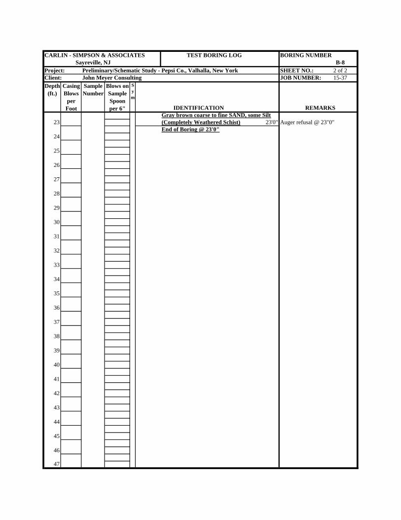
CARLIN - SIMPSON & ASSOCIATES TEST BORING LOG BORING NUMBERSayreville, NJ B-8
Project: Preliminary/Schematic Study - Pepsi Co., Valhalla, New York SHEET NO.: 2 of 2Client: John Meyer Consulting JOB NUMBER: 15-37Depth
(ft.)Casing Blows
per Foot
Sample Number
Blows on Sample Spoon per 6" IDENTIFICATION REMARKS
Gray brown coarse to fine SAND, some Silt23 (Completely Weathered Schist) 23'0" Auger refusal @ 23"0"
End of Boring @ 23'0"24
25
26
27
28
29
30
31
32
33
34
35
36
37
38
39
40
41
42
43
44
45
46
47
Sym
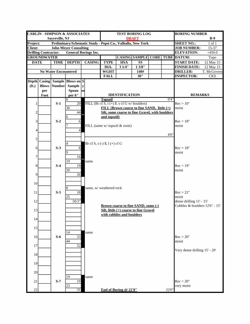
CARLIN - SIMPSON & ASSOCIATES TEST BORING LOG BORING NUMBERSayreville, NJ B-9
Project: Preliminary/Schematic Study - Pepsi Co., Valhalla, New York SHEET NO.: 1 of 1Client: John Meyer Consulting JOB NUMBER: 15-37Drilling Contractor: General Borings Inc. ELEVATION: +450.0GROUNDWATER CASING SAMPLE CORE TUBE DATUM: Topo DATE TIME DEPTH CASING TYPE HSA SS START DATE: 12 May 15
DIA. 3 1/4" 1 3/8" FINISH DATE: 12 May 15No Water Encountered WGHT 140# DRILLER: T. McGovern
FALL 30" INSPECTOR: CKSDepth
(ft.)Casing Blows
per Foot
Sample Number
Blows on Sample Spoon per 6" IDENTIFICATION REMARKS
6 Topsoil 0'4"1 S-1 20 FILL (Br cf S, l (+) $. s cf G w/ boulders) Rec = 10"
36 FILL (Brown coarse to fine SAND, little (+) moist2 44 Silt, some coarse to fine Gravel, with boulders
6 and topsoil)3 S-2 6 Rec = 18"
7 FILL (same w/ topsoil & roots) moist4 4
4'6"5
4 Br cf S, s (-) $, l (+) cf G6 S-3 8 Rec = 18"
9 moist7 16
19 same8 S-4 19 Rec = 19"
20 moist9 26
108 same, w/ weathered rock
11 S-5 18 Rec = 21"25 moist
12 50/3" dense drilling 11' - 15'Brown coarse to fine SAND, some (-) Cobbles & boulders 12'6" - 15'
13 Silt, little (+) coarse to fine Gravelwith cobbles and boulders
14
1514 same
16 S-6 33 Rec = 20"44 moist
17 52Very dense drilling 15' - 20'
18
19
2019 same
21 S-7 19 Rec = 20"23 very moist
22 31 End of Boring @ 22'0" 22'0"
Sym
DRAFT
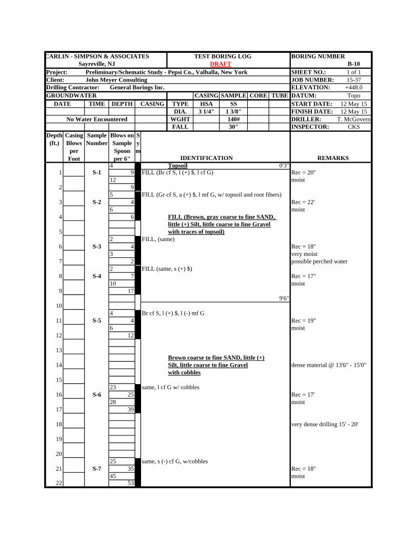
CARLIN - SIMPSON & ASSOCIATES TEST BORING LOG BORING NUMBERSayreville, NJ B-10
Project: Preliminary/Schematic Study - Pepsi Co., Valhalla, New York SHEET NO.: 1 of 1Client: John Meyer Consulting JOB NUMBER: 15-37Drilling Contractor: General Borings Inc. ELEVATION: +448.0GROUNDWATER CASING SAMPLE CORE TUBE DATUM: Topo DATE TIME DEPTH CASING TYPE HSA SS START DATE: 12 May 15
DIA. 3 1/4" 1 3/8" FINISH DATE: 12 May 15No Water Encountered WGHT 140# DRILLER: T. McGovern
FALL 30" INSPECTOR: CKSDepth
(ft.)Casing Blows
per Foot
Sample Number
Blows on Sample Spoon per 6" IDENTIFICATION REMARKS
4 Topsoil 0'3"1 S-1 9 FILL (Br cf S, l (+) $, l cf G) Rec = 20"
12 moist2 9
5 FILL (Gr cf S, a (+) $, l mf G, w/ topsoil and root fibers)3 S-2 4 Rec = 22'
6 moist4 6 FILL (Brown, gray coarse to fine SAND,
little (+) Silt, little coarse to fine Gravel5 with traces of topsoil)
2 FILL, (same)6 S-3 4 Rec = 18"
3 very moist7 2 possible perched water
2 FILL (same, s (+) $)8 S-4 7 Rec = 17"
10 moist9 17
9'6"10
4 Br cf S, l (+) $, l (-) mf G11 S-5 4 Rec = 19"
6 moist12 12
13Brown coarse to fine SAND, little (+)
14 Silt, little coarse to fine Gravel dense material @ 13'6" - 15'0"with cobbles
1523 same, l cf G w/ cobbles
16 S-6 25 Rec = 17' 28 moist
17 39
18 very dense drilling 15' - 20'
19
2025 same, s (-) cf G, w/cobbles
21 S-7 35 Rec = 18"45 moist
22 53
Sym
DRAFT
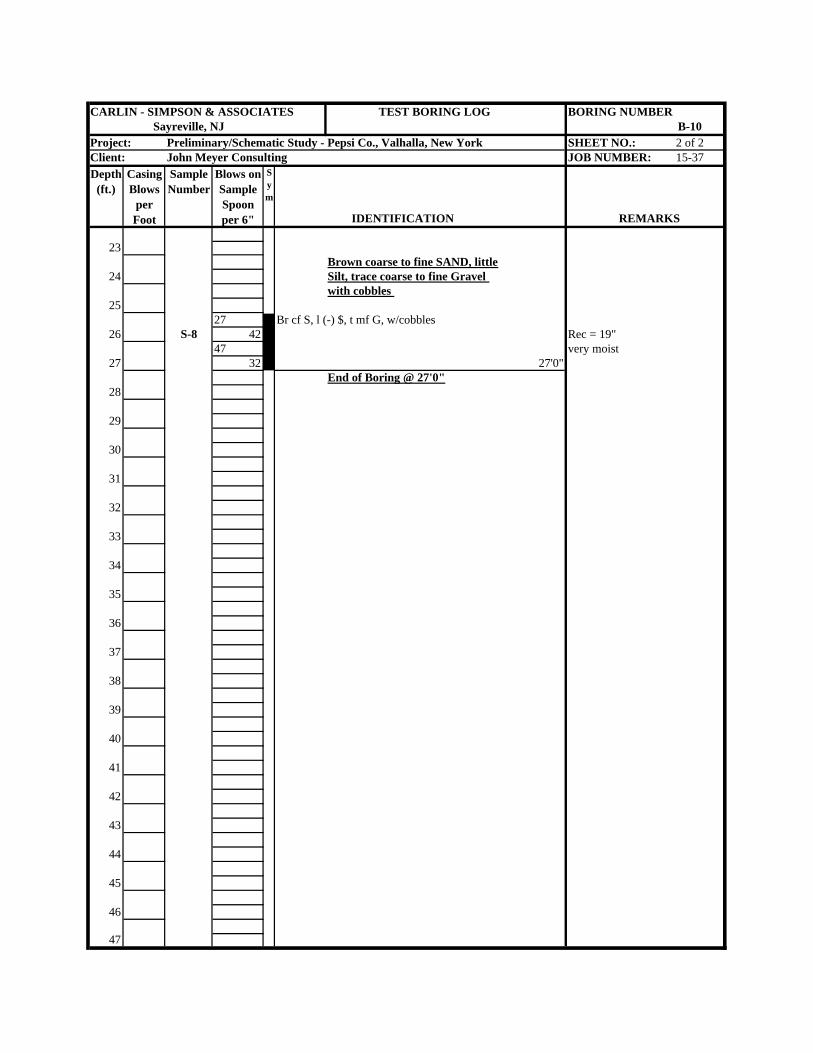
CARLIN - SIMPSON & ASSOCIATES TEST BORING LOG BORING NUMBERSayreville, NJ B-10
Project: Preliminary/Schematic Study - Pepsi Co., Valhalla, New York SHEET NO.: 2 of 2Client: John Meyer Consulting JOB NUMBER: 15-37Depth
(ft.)Casing Blows
per Foot
Sample Number
Blows on Sample Spoon per 6" IDENTIFICATION REMARKS
23Brown coarse to fine SAND, little
24 Silt, trace coarse to fine Gravel with cobbles
2527 Br cf S, l (-) $, t mf G, w/cobbles
26 S-8 42 Rec = 19"47 very moist
27 32 27'0"End of Boring @ 27'0"
28
29
30
31
32
33
34
35
36
37
38
39
40
41
42
43
44
45
46
47
Sym
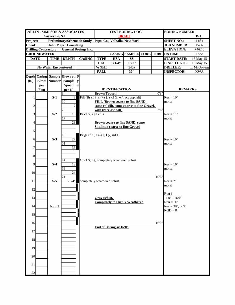
CARLIN - SIMPSON & ASSOCIATES TEST BORING LOG BORING NUMBERSayreville, NJ B-11
Project: Preliminary/Schematic Study - Pepsi Co., Valhalla, New York SHEET NO.: 1 of 1Client: John Meyer Consulting JOB NUMBER: 15-37Drilling Contractor: General Borings Inc. ELEVATION: +462.0GROUNDWATER CASING SAMPLE CORE TUBE DATUM: Topo DATE TIME DEPTH CASING TYPE HSA SS START DATE: 13 May 15
DIA. 3 1/4" 1 3/8" FINISH DATE: 13 May 15No Water Encountered WGHT 140# DRILLER: T. McGovern
FALL 30" INSPECTOR: KWADepth
(ft.)Casing Blows
per Foot
Sample Number
Blows on Sample Spoon per 6" IDENTIFICATION REMARKS
3 Brown Topsoil 0'3"1 S-1 3 Fill (Br cf S, s (+) $, s cf G, w/trace asphalt) Rec = 10"
10 FILL (Brown coarse to fine SAND, moist2 7 some (+) Silt, some coarse to fine Gravel,
7 with trace asphalt) 2'6"3 S-2 10 Br cf S, s $ l cf G Rec = 11"
17 moist4 28 Brown coarse to fine SAND, some
Silt, little coarse to fine Gravel5
15 Br gr cf S, s (-) $, l (-) mf G6 S-3 27 Rec = 16"
31 moist7 36
814 Gr cf S, l $, completely weathered schist
9 S-4 18 Rec = 16"16 moist
10 2421 10'6"
11 S-5 75/4" completely weathered schist Rec = 2"moist
12Run 1
13 Gray Schist, 11'0" - 16'0"Completely to Highly Weathered Run = 60"
14 Run 1 Rec = 30", 50%RQD = 0
15
16 16'0"End of Boring @ 16'0"
17
18
19
20
21
22
Sym
DRAFT
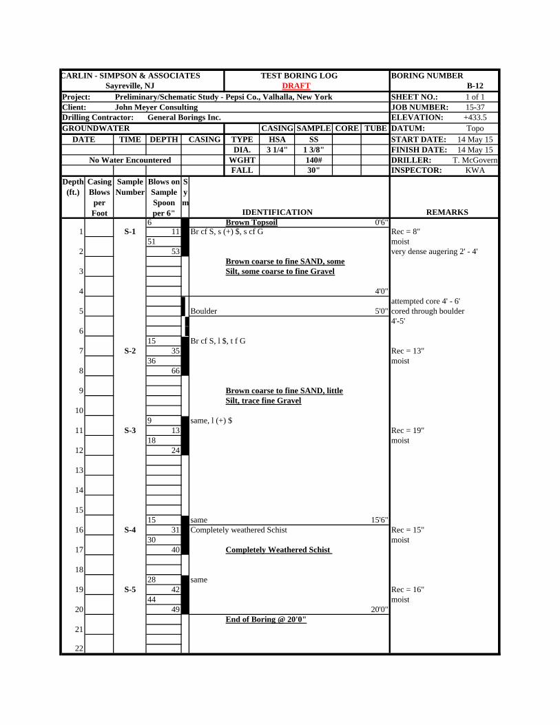
CARLIN - SIMPSON & ASSOCIATES TEST BORING LOG BORING NUMBERSayreville, NJ B-12
Project: Preliminary/Schematic Study - Pepsi Co., Valhalla, New York SHEET NO.: 1 of 1Client: John Meyer Consulting JOB NUMBER: 15-37Drilling Contractor: General Borings Inc. ELEVATION: +433.5GROUNDWATER CASING SAMPLE CORE TUBE DATUM: Topo DATE TIME DEPTH CASING TYPE HSA SS START DATE: 14 May 15
DIA. 3 1/4" 1 3/8" FINISH DATE: 14 May 15No Water Encountered WGHT 140# DRILLER: T. McGovern
FALL 30" INSPECTOR: KWADepth
(ft.)Casing Blows
per Foot
Sample Number
Blows on Sample Spoon per 6" IDENTIFICATION REMARKS
6 Brown Topsoil 0'6"1 S-1 11 Br cf S, s (+) $, s cf G Rec = 8"
51 moist2 53 very dense augering 2' - 4'
Brown coarse to fine SAND, some3 Silt, some coarse to fine Gravel
4 4'0"attempted core 4' - 6'
5 Boulder 5'0" cored through boulder4'-5'
615 Br cf S, l $, t f G
7 S-2 35 Rec = 13"36 moist
8 66
9 Brown coarse to fine SAND, littleSilt, trace fine Gravel
109 same, l (+) $
11 S-3 13 Rec = 19"18 moist
12 24
13
14
1515 same 15'6"
16 S-4 31 Completely weathered Schist Rec = 15"30 moist
17 40 Completely Weathered Schist
1828 same
19 S-5 42 Rec = 16"44 moist
20 49 20'0"End of Boring @ 20'0"
21
22
Sym
DRAFT
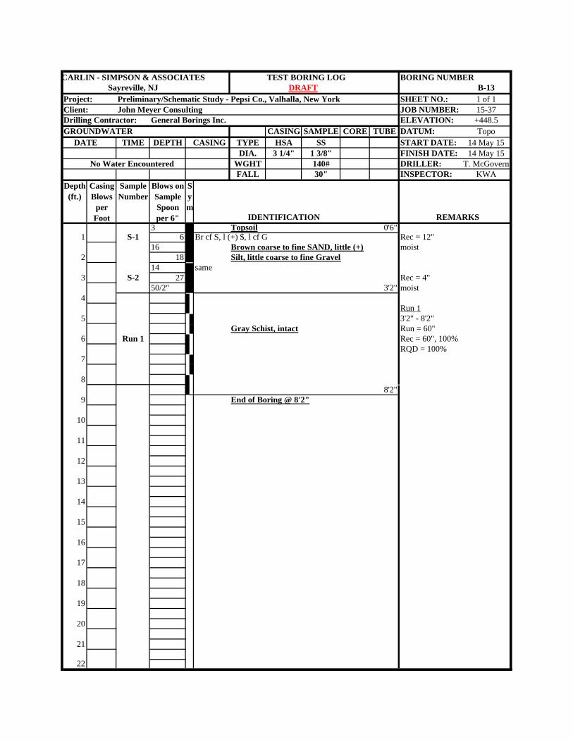
CARLIN - SIMPSON & ASSOCIATES TEST BORING LOG BORING NUMBERSayreville, NJ B-13
Project: Preliminary/Schematic Study - Pepsi Co., Valhalla, New York SHEET NO.: 1 of 1Client: John Meyer Consulting JOB NUMBER: 15-37Drilling Contractor: General Borings Inc. ELEVATION: +448.5GROUNDWATER CASING SAMPLE CORE TUBE DATUM: Topo DATE TIME DEPTH CASING TYPE HSA SS START DATE: 14 May 15
DIA. 3 1/4" 1 3/8" FINISH DATE: 14 May 15No Water Encountered WGHT 140# DRILLER: T. McGovern
FALL 30" INSPECTOR: KWADepth
(ft.)Casing Blows
per Foot
Sample Number
Blows on Sample Spoon per 6" IDENTIFICATION REMARKS
3 Topsoil 0'6"1 S-1 6 Br cf S, l (+) $, l cf G Rec = 12"
16 Brown coarse to fine SAND, little (+) moist2 18 Silt, little coarse to fine Gravel
14 same3 S-2 27 Rec = 4"
50/2" 3'2" moist4
Run 15 3'2" - 8'2"
Gray Schist, intact Run = 60"6 Run 1 Rec = 60", 100%
RQD = 100%7
88'2"
9 End of Boring @ 8'2"
10
11
12
13
14
15
16
17
18
19
20
21
22
Sym
DRAFT
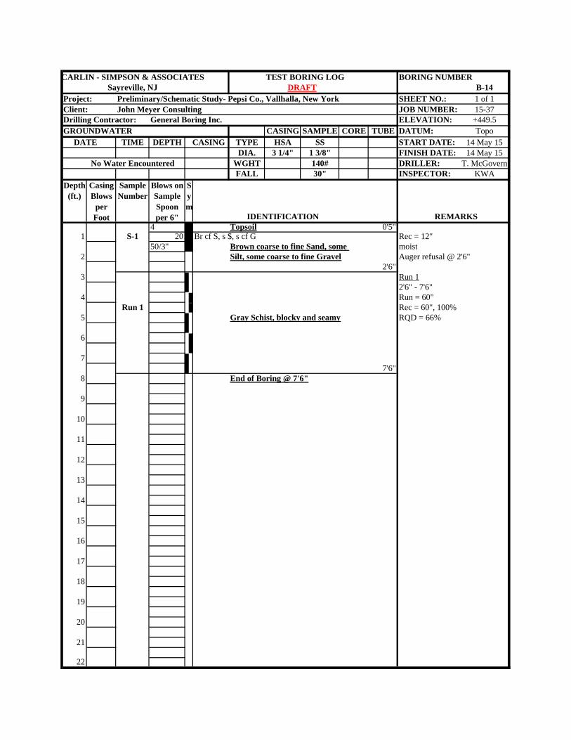
CARLIN - SIMPSON & ASSOCIATES TEST BORING LOG BORING NUMBERSayreville, NJ B-14
Project: Preliminary/Schematic Study- Pepsi Co., Vallhalla, New York SHEET NO.: 1 of 1Client: John Meyer Consulting JOB NUMBER: 15-37Drilling Contractor: General Boring Inc. ELEVATION: +449.5GROUNDWATER CASING SAMPLE CORE TUBE DATUM: Topo DATE TIME DEPTH CASING TYPE HSA SS START DATE: 14 May 15
DIA. 3 1/4" 1 3/8" FINISH DATE: 14 May 15No Water Encountered WGHT 140# DRILLER: T. McGovern
FALL 30" INSPECTOR: KWADepth
(ft.)Casing Blows
per Foot
Sample Number
Blows on Sample Spoon per 6" IDENTIFICATION REMARKS
4 Topsoil 0'5"1 S-1 20 Br cf S, s $, s cf G Rec = 12"
50/3" Brown coarse to fine Sand, some moist2 Silt, some coarse to fine Gravel Auger refusal @ 2'6"
2'6"3 Run 1
2'6" - 7'6"4 Run = 60"
Run 1 Rec = 60", 100%5 Gray Schist, blocky and seamy RQD = 66%
6
77'6"
8 End of Boring @ 7'6"
9
10
11
12
13
14
15
16
17
18
19
20
21
22
Sym
DRAFT
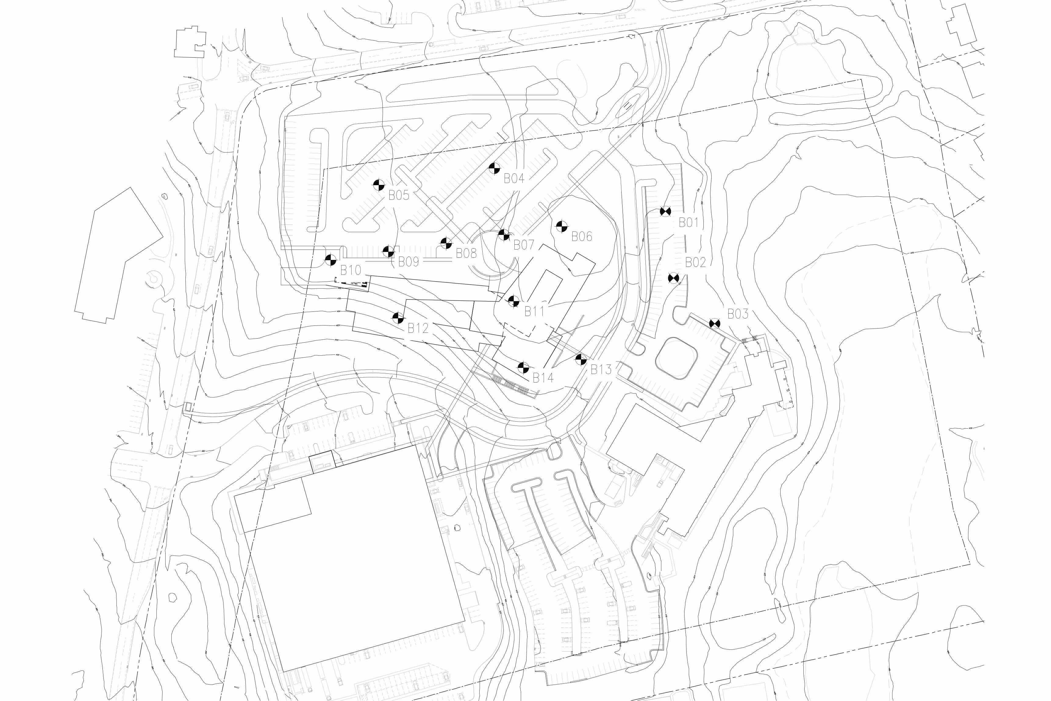
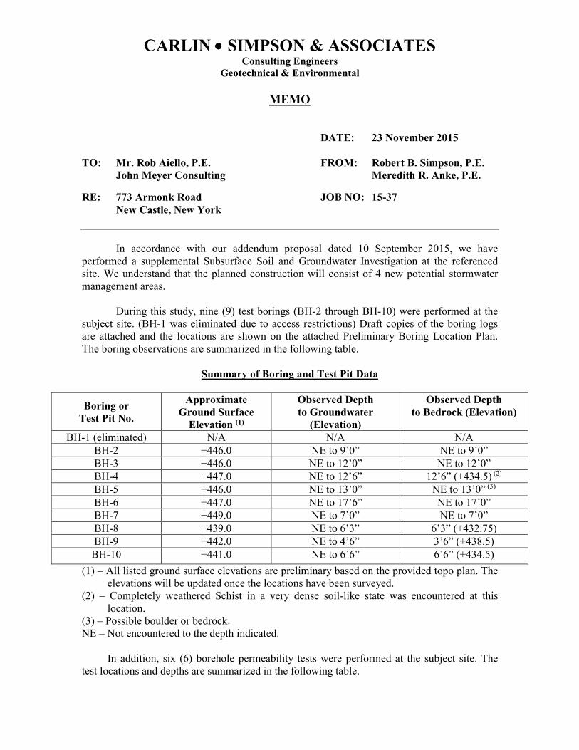
CARLIN •••• SIMPSON & ASSOCIATES Consulting Engineers
Geotechnical & Environmental
MEMO
DATE: 23 November 2015
TO: Mr. Rob Aiello, P.E. FROM: Robert B. Simpson, P.E.
John Meyer Consulting Meredith R. Anke, P.E.
RE: 773 Armonk Road JOB NO: 15-37
New Castle, New York
In accordance with our addendum proposal dated 10 September 2015, we have
performed a supplemental Subsurface Soil and Groundwater Investigation at the referenced
site. We understand that the planned construction will consist of 4 new potential stormwater
management areas.
During this study, nine (9) test borings (BH-2 through BH-10) were performed at the
subject site. (BH-1 was eliminated due to access restrictions) Draft copies of the boring logs
are attached and the locations are shown on the attached Preliminary Boring Location Plan.
The boring observations are summarized in the following table.
Summary of Boring and Test Pit Data
Boring or
Test Pit No.
Approximate
Ground Surface
Elevation (1)
Observed Depth
to Groundwater
(Elevation)
Observed Depth
to Bedrock (Elevation)
BH-1 (eliminated) N/A N/A N/A
BH-2 +446.0 NE to 9’0” NE to 9’0”
BH-3 +446.0 NE to 12’0” NE to 12’0”
BH-4 +447.0 NE to 12’6” 12’6” (+434.5) (2)
BH-5 +446.0 NE to 13’0” NE to 13’0” (3)
BH-6 +447.0 NE to 17’6” NE to 17’0”
BH-7 +449.0 NE to 7’0” NE to 7’0”
BH-8 +439.0 NE to 6’3” 6’3” (+432.75)
BH-9 +442.0 NE to 4’6” 3’6” (+438.5)
BH-10 +441.0 NE to 6’6” 6’6” (+434.5)
(1) – All listed ground surface elevations are preliminary based on the provided topo plan. The
elevations will be updated once the locations have been surveyed.
(2) – Completely weathered Schist in a very dense soil-like state was encountered at this
location.
(3) – Possible boulder or bedrock.
NE – Not encountered to the depth indicated.
In addition, six (6) borehole permeability tests were performed at the subject site. The
test locations and depths are summarized in the following table.
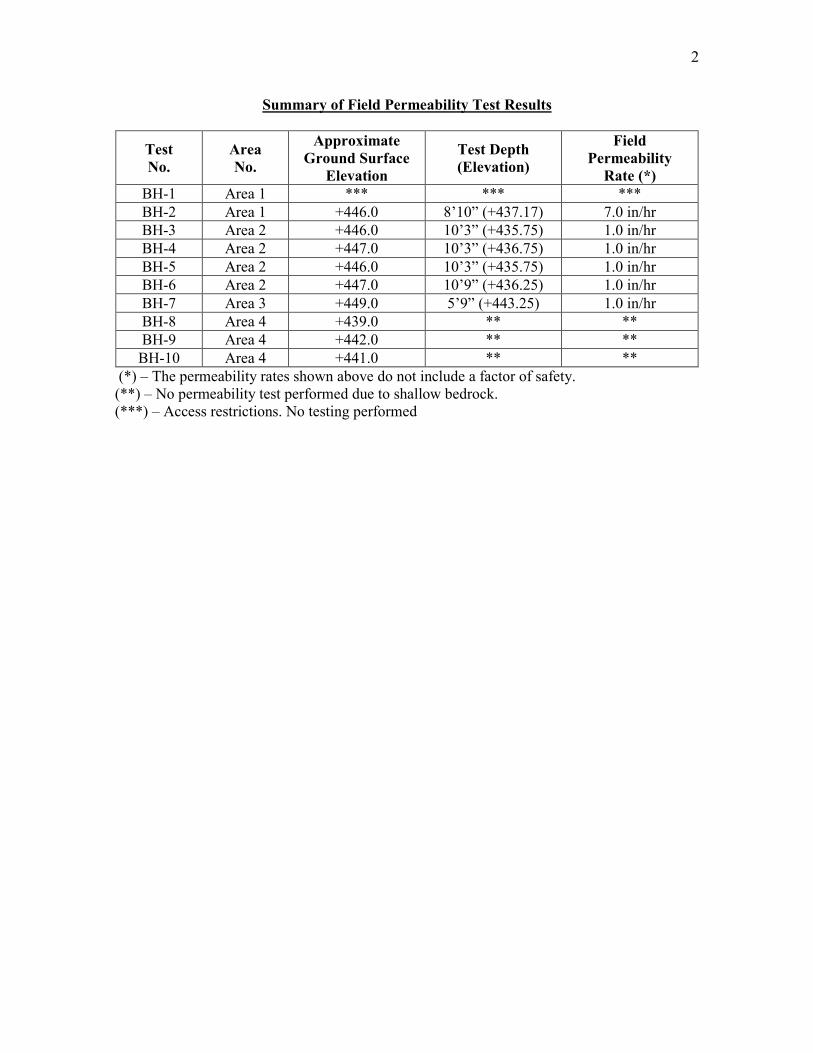
2
Summary of Field Permeability Test Results
Test
No.
Area
No.
Approximate
Ground Surface
Elevation
Test Depth
(Elevation)
Field
Permeability
Rate (*)
BH-1 Area 1 *** *** ***
BH-2 Area 1 +446.0 8’10” (+437.17) 7.0 in/hr
BH-3 Area 2 +446.0 10’3” (+435.75) 1.0 in/hr
BH-4 Area 2 +447.0 10’3” (+436.75) 1.0 in/hr
BH-5 Area 2 +446.0 10’3” (+435.75) 1.0 in/hr
BH-6 Area 2 +447.0 10’9” (+436.25) 1.0 in/hr
BH-7 Area 3 +449.0 5’9” (+443.25) 1.0 in/hr
BH-8 Area 4 +439.0 ** **
BH-9 Area 4 +442.0 ** **
BH-10 Area 4 +441.0 ** **
(*) – The permeability rates shown above do not include a factor of safety.
(**) – No permeability test performed due to shallow bedrock.
(***) – Access restrictions. No testing performed
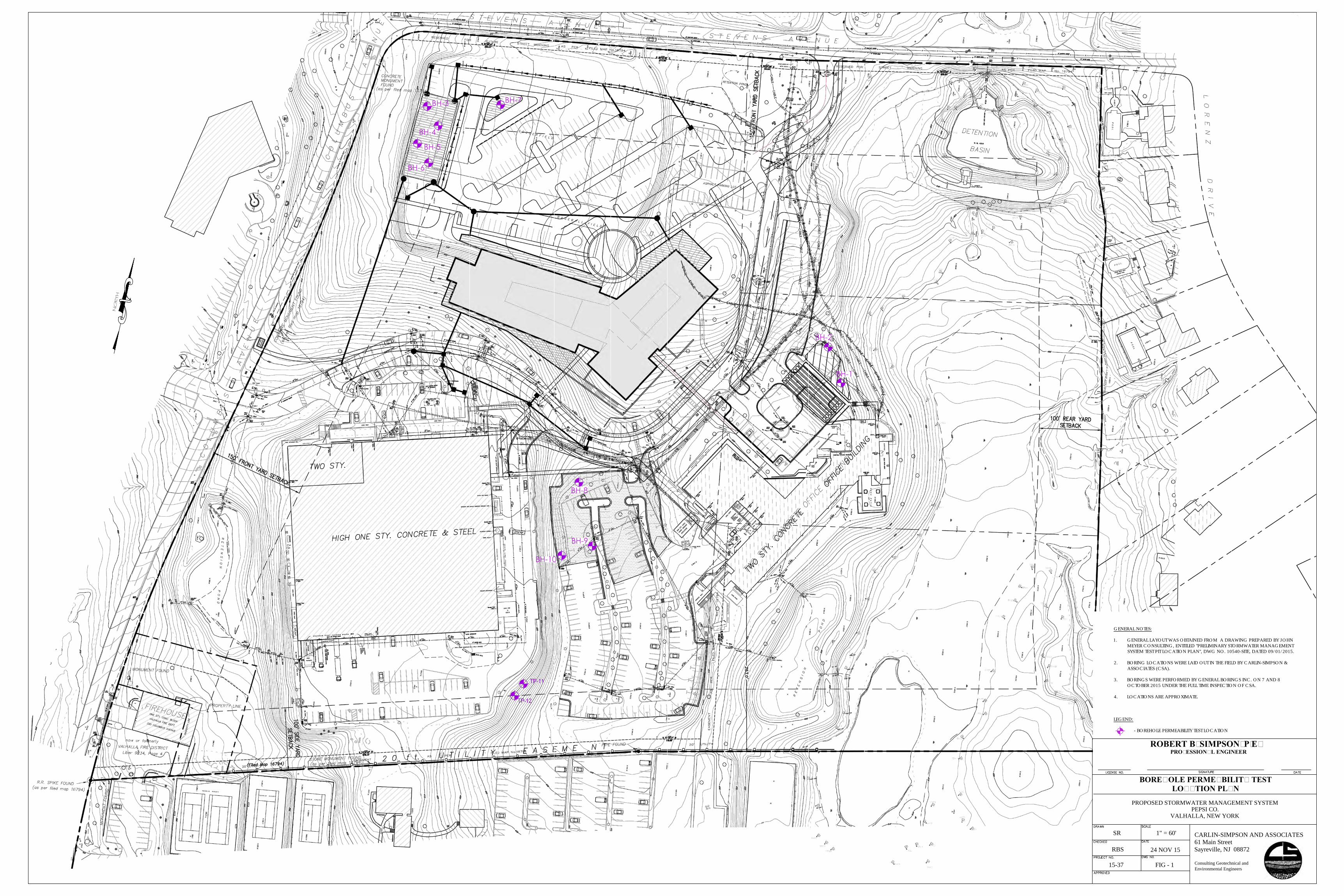
ROBERT B. SIMPSON, P.E.PROFESSIONAL ENGINEER
1" = 60'SR
FIG - 115-37
24 NOV 15RBS
BOREHOLE PERMEABILITY TESTLOCATION PLAN
PROPOSED STORMWATER MANAGEMENT SYSTEMPEPSI CO.
VALHALLA, NEW YORK
CARLIN-SIMPSON AND ASSOCIATES61 Main StreetSayreville, NJ 08872
Consulting Geotechnical andEnvironmental Engineers
GENERAL NOTES:
1. GENERAL LAYOUT WAS OBTAINED FROM A DRAWING PREPARED BY JOHNMEYER CONSULTING, ENTITLED "PRELIMINARY STORMWATER MANAGEMENTSYSTEM TEST PIT LOCATION PLAN", DWG NO. 10540-SITE, DATED 09/01/2015.
2. BORING LOCATIONS WERE LAID OUT IN THE FIELD BY CARLIN-SIMPSON &ASSOCIATES (CSA).
3. BORINGS WERE PERFORMED BY GENERAL BORINGS INC. ON 7 AND 8OCTOBER 2015 UNDER THE FULL TIME INSPECTION OF CSA.
4. LOCATIONS ARE APPROXIMATE.
LEGEND:
- BOREHOLE PERMEABILITY TEST LOCATION
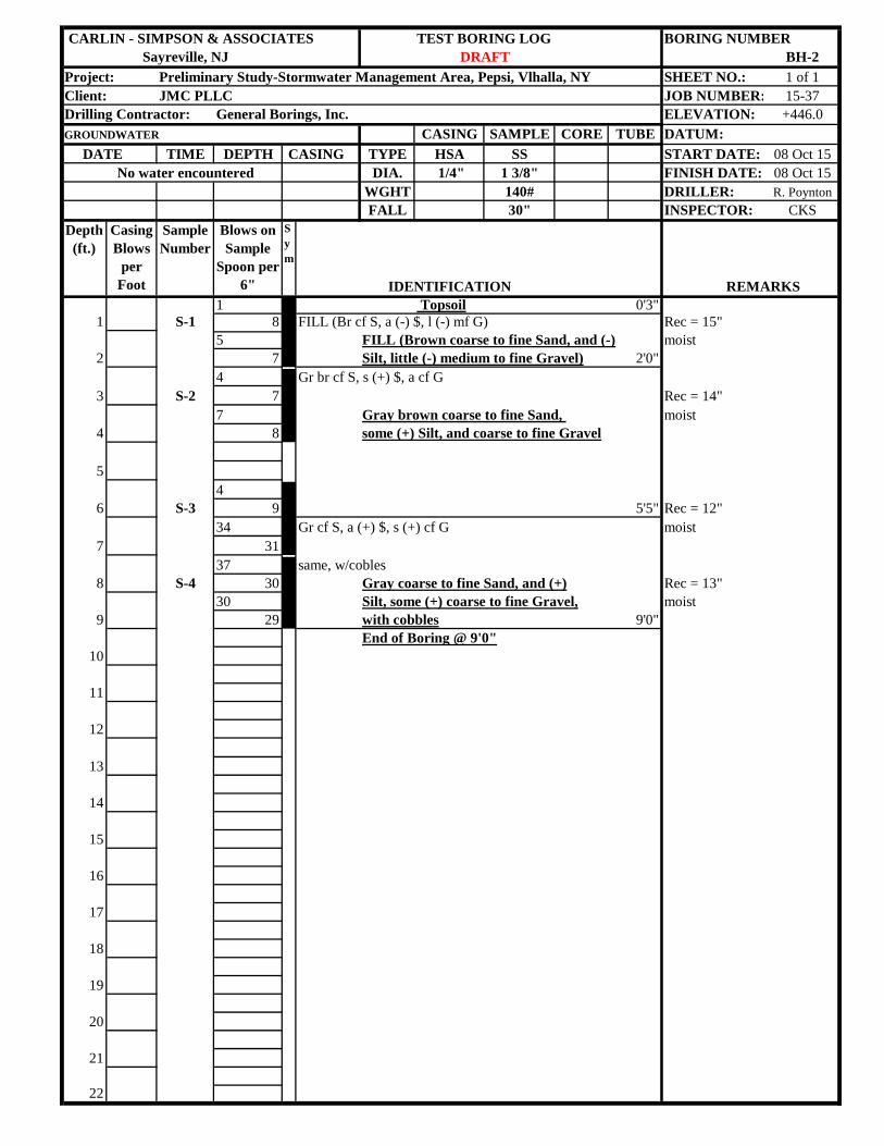
CARLIN - SIMPSON & ASSOCIATES TEST BORING LOG BORING NUMBERSayreville, NJ BH-2
Project: Preliminary Study-Stormwater Management Area, Pepsi, Vlhalla, NY SHEET NO.: 1 of 1Client: JMC PLLC JOB NUMBER: 15-37Drilling Contractor: General Borings, Inc. ELEVATION: +446.0GROUNDWATER CASING SAMPLE CORE TUBE DATUM: DATE TIME DEPTH CASING TYPE HSA SS START DATE: 08 Oct 15
No water encountered DIA. 1/4" 1 3/8" FINISH DATE: 08 Oct 15WGHT 140# DRILLER: R. PoyntonFALL 30" INSPECTOR: CKS
Depth (ft.)
Casing Blows
per Foot
Sample Number
Blows on Sample
Spoon per 6"
Sym
IDENTIFICATION REMARKS1 Topsoil 0'3"
1 S-1 8 FILL (Br cf S, a (-) $, l (-) mf G) Rec = 15"5 FILL (Brown coarse to fine Sand, and (-) moist
2 7 Silt, little (-) medium to fine Gravel) 2'0"4 Gr br cf S, s (+) $, a cf G
3 S-2 7 Rec = 14"7 Gray brown coarse to fine Sand, moist
4 8 some (+) Silt, and coarse to fine Gravel
54
6 S-3 9 5'5" Rec = 12"34 Gr cf S, a (+) $, s (+) cf G moist
7 3137 same, w/cobles
8 S-4 30 Gray coarse to fine Sand, and (+) Rec = 13"30 Silt, some (+) coarse to fine Gravel, moist
9 29 with cobbles 9'0"End of Boring @ 9'0"
10
11
12
13
14
15
16
17
18
19
20
21
22
DRAFT
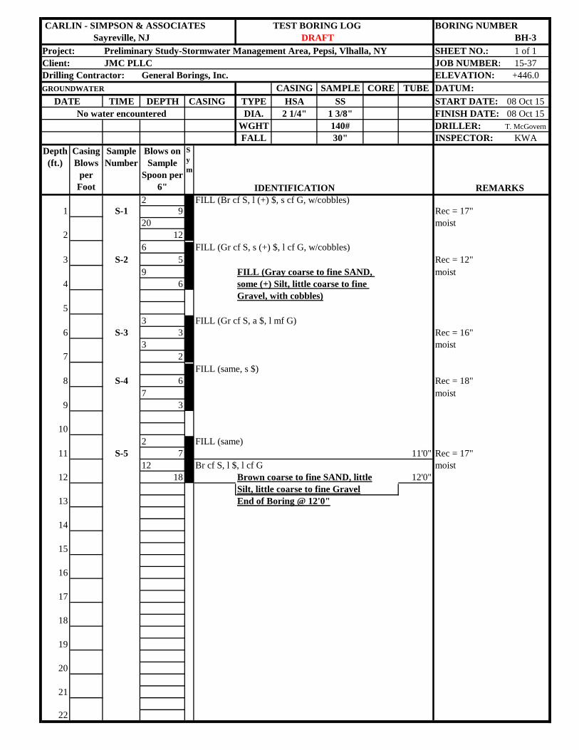
CARLIN - SIMPSON & ASSOCIATES TEST BORING LOG BORING NUMBERSayreville, NJ BH-3
Project: Preliminary Study-Stormwater Management Area, Pepsi, Vlhalla, NY SHEET NO.: 1 of 1Client: JMC PLLC JOB NUMBER: 15-37Drilling Contractor: General Borings, Inc. ELEVATION: +446.0GROUNDWATER CASING SAMPLE CORE TUBE DATUM: DATE TIME DEPTH CASING TYPE HSA SS START DATE: 08 Oct 15
No water encountered DIA. 2 1/4" 1 3/8" FINISH DATE: 08 Oct 15WGHT 140# DRILLER: T. McGovernFALL 30" INSPECTOR: KWA
Depth (ft.)
Casing Blows
per Foot
Sample Number
Blows on Sample
Spoon per 6"
Sym
IDENTIFICATION REMARKS2 FILL (Br cf S, l (+) $, s cf G, w/cobbles)
1 S-1 9 Rec = 17"20 moist
2 126 FILL (Gr cf S, s (+) $, l cf G, w/cobbles)
3 S-2 5 Rec = 12"9 FILL (Gray coarse to fine SAND, moist
4 6 some (+) Silt, little coarse to fine Gravel, with cobbles)
53 FILL (Gr cf S, a $, l mf G)
6 S-3 3 Rec = 16"3 moist
7 2FILL (same, s $)
8 S-4 6 Rec = 18"7 moist
9 3
102 FILL (same)
11 S-5 7 11'0" Rec = 17"12 Br cf S, l $, l cf G moist
12 18 Brown coarse to fine SAND, little 12'0"Silt, little coarse to fine Gravel
13 End of Boring @ 12'0"
14
15
16
17
18
19
20
21
22
DRAFT
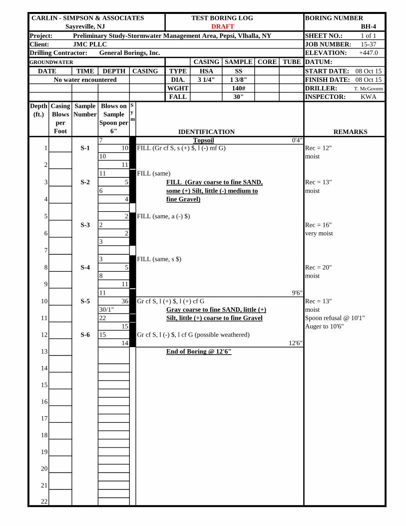
CARLIN - SIMPSON & ASSOCIATES TEST BORING LOG BORING NUMBERSayreville, NJ BH-4
Project: Preliminary Study-Stormwater Management Area, Pepsi, Vlhalla, NY SHEET NO.: 1 of 1Client: JMC PLLC JOB NUMBER: 15-37Drilling Contractor: General Borings, Inc. ELEVATION: +447.0GROUNDWATER CASING SAMPLE CORE TUBE DATUM: DATE TIME DEPTH CASING TYPE HSA SS START DATE: 08 Oct 15
No water encountered DIA. 3 1/4" 1 3/8" FINISH DATE: 08 Oct 15WGHT 140# DRILLER: T. McGovernFALL 30" INSPECTOR: KWA
Depth (ft.)
Casing Blows
per Foot
Sample Number
Blows on Sample
Spoon per 6"
Sym
IDENTIFICATION REMARKS7 Topsoil 0'4"
1 S-1 10 FILL (Gr cf S, s (+) $, l (-) mf G) Rec = 12"10 moist
2 1111 FILL (same)
3 S-2 5 FILL (Gray coarse to fine SAND, Rec = 13"6 some (+) Silt, little (-) medium to moist
4 4 fine Gravel)
5 2 FILL (same, a (-) $)S-3 2 Rec = 16"
6 2 very moist3
73 FILL (same, s $)
8 S-4 5 Rec = 20"8 moist
9 1111 9'6"
10 S-5 36 Gr cf S, l (+) $, l (+) cf G Rec = 13"30/1" Gray coarse to fine SAND, little (+) moist
11 22 Silt, little (+) coarse to fine Gravel Spoon refusal @ 10'1"15 Auger to 10'6"
12 S-6 15 Gr cf S, l (-) $, l cf G (possible weathered)14 12'6"
13 End of Boring @ 12'6"
14
15
16
17
18
19
20
21
22
DRAFT
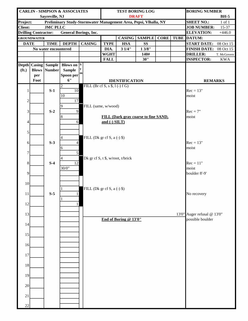
CARLIN - SIMPSON & ASSOCIATES TEST BORING LOG BORING NUMBERSayreville, NJ BH-5
Project: Preliminary Study-Stormwater Management Area, Pepsi, Vlhalla, NY SHEET NO.: 1 of 1Client: JMC PLLC JOB NUMBER: 15-37Drilling Contractor: General Borings, Inc. ELEVATION: +446.0GROUNDWATER CASING SAMPLE CORE TUBE DATUM: DATE TIME DEPTH CASING TYPE HSA SS START DATE: 08 Oct 15
No water encountered DIA. 3 1/4" 1 3/8" FINISH DATE: 08 Oct 15WGHT 140# DRILLER: T. McGovernFALL 30" INSPECTOR: KWA
Depth (ft.)
Casing Blows
per Foot
Sample Number
Blows on Sample
Spoon per 6"
Sym
IDENTIFICATION REMARKS2 FILL (Br cf S, s $, l (-) f G)
1 S-1 10 Rec = 13"10 moist
2 179 FILL (same, w/wood)
3 S-2 9 Rec = 7"8 FILL (Dark gray coarse to fine SAND, moist
4 6 and (-) SILT)
54 FILL (Dk gr cf S, a (-) $)
6 S-3 4 Rec = 13"6 moist
7 54 Dk gr cf S, t $, w/root, t/brick
8 S-4 12 Rec = 11"30/0" moist
9 boulder 8'-9'
101 FILL (Dk gr cf S, a (-) $)
11 S-5 1 No recovery1
12 1
13 13'0" Auger refusal @ 13'0"End of Boring @ 13'0" possible boulder
14
15
16
17
18
19
20
21
22
DRAFT
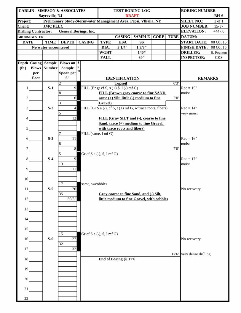
CARLIN - SIMPSON & ASSOCIATES TEST BORING LOG BORING NUMBERSayreville, NJ BH-6
Project: Preliminary Study-Stormwater Management Area, Pepsi, Vlhalla, NY SHEET NO.: 1 of 1Client: JMC PLLC JOB NUMBER: 15-37Drilling Contractor: General Borings, Inc. ELEVATION: +447.0GROUNDWATER CASING SAMPLE CORE TUBE DATUM: DATE TIME DEPTH CASING TYPE HSA SS START DATE: 08 Oct 15
No water encountered DIA. 3 1/4" 1 3/8" FINISH DATE: 08 Oct 15WGHT 140# DRILLER: R. PoyntonFALL 30" INSPECTOR: CKS
Depth (ft.)
Casing Blows
per Foot
Sample Number
Blows on Sample
Spoon per 6"
Sym
IDENTIFICATION REMARKS2 Topsoil 0'3"
1 S-1 9 FILL (Br gr cf S, s (+) $, l (-) mf G) Rec = 15"8 FILL (Brown gray coarse to fine SAND, moist
2 6 some (+) Silt, little (-) medium to fine 2'0"3 Gravel)
3 S-2 4 FILL (Gr $ a (-), cf S, t (+) mf G, w/trace roots, fibers) Rec = 14"5 very moist
4 12 FILL (Gray SILT and (-), coarse to fineSand, trace (+) medium to fine Gravel,
5 with trace roots and fibers)7 FILL (same, l mf G)
6 S-3 11 Rec = 16"8 moist
7 8 7'0"5 Gr cf S a (-), $, l mf G)
8 S-4 9 Rec = 17"13 moist
9 11
1017 same, w/cobbles
11 S-5 26 No recovery35 Gray coarse to fine Sand, and (-) Silt,
12 50/5" little medium to fine Gravel, with cobbles
13
14
1515 Gr cf S a (-), $, l mf G)
16 S-6 27 No recovery32
17 3217'6" very dense drilling
18 End of Boring @ 17'6"
19
20
21
22
DRAFT
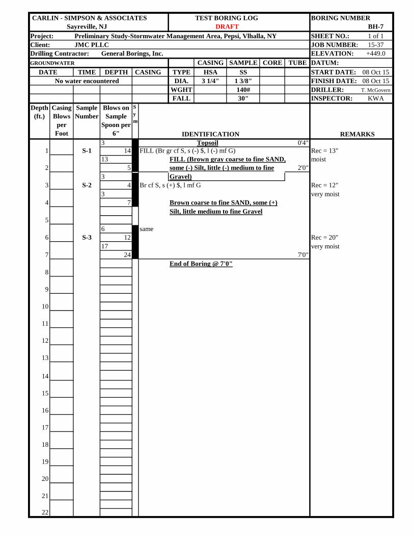
CARLIN - SIMPSON & ASSOCIATES TEST BORING LOG BORING NUMBERSayreville, NJ BH-7
Project: Preliminary Study-Stormwater Management Area, Pepsi, Vlhalla, NY SHEET NO.: 1 of 1Client: JMC PLLC JOB NUMBER: 15-37Drilling Contractor: General Borings, Inc. ELEVATION: +449.0GROUNDWATER CASING SAMPLE CORE TUBE DATUM: DATE TIME DEPTH CASING TYPE HSA SS START DATE: 08 Oct 15
No water encountered DIA. 3 1/4" 1 3/8" FINISH DATE: 08 Oct 15WGHT 140# DRILLER: T. McGovernFALL 30" INSPECTOR: KWA
Depth (ft.)
Casing Blows
per Foot
Sample Number
Blows on Sample
Spoon per 6"
Sym
IDENTIFICATION REMARKS3 Topsoil 0'4"
1 S-1 14 FILL (Br gr cf S, s (-) $, l (-) mf G) Rec = 13"13 FILL (Brown gray coarse to fine SAND, moist
2 5 some (-) Silt, little (-) medium to fine 2'0"3 Gravel)
3 S-2 4 Br cf S, s (+) $, l mf G Rec = 12"3 very moist
4 7 Brown coarse to fine SAND, some (+)Silt, little medium to fine Gravel
56 same
6 S-3 12 Rec = 20"17 very moist
7 24 7'0"End of Boring @ 7'0"
8
9
10
11
12
13
14
15
16
17
18
19
20
21
22
DRAFT
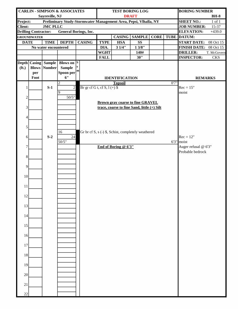
CARLIN - SIMPSON & ASSOCIATES TEST BORING LOG BORING NUMBERSayreville, NJ BH-8
Project: Preliminary Study-Stormwater Management Area, Pepsi, Vlhalla, NY SHEET NO.: 1 of 1Client: JMC PLLC JOB NUMBER: 15-37Drilling Contractor: General Borings, Inc. ELEVATION: +439.0GROUNDWATER CASING SAMPLE CORE TUBE DATUM: DATE TIME DEPTH CASING TYPE HSA SS START DATE: 08 Oct 15
No water encountered DIA. 3 1/4" 1 3/8" FINISH DATE: 08 Oct 15WGHT 140# DRILLER: T. McGovernFALL 30" INSPECTOR: CKS
Depth (ft.)
Casing Blows
per Foot
Sample Number
Blows on Sample
Spoon per 6"
Sym
IDENTIFICATION REMARKS2 Topsoil 0'7"
1 S-1 2 Br gr cf G t, cf S, l (+) $ Rec = 15"9 moist
2 50/5"Brown gray coarse to fine GRAVEL
3 trace, coarse to fine Sand, little (+) Silt
4
516 Gr br cf S, s (-) $, Schist, completely weathered
6 S-2 24 Rec = 12"50/5" 6'3" moist
7 End of Boring @ 6'3" Auger refusal @ 6'3"Probable bedrock
8
9
10
11
12
13
14
15
16
17
18
19
20
21
22
DRAFT
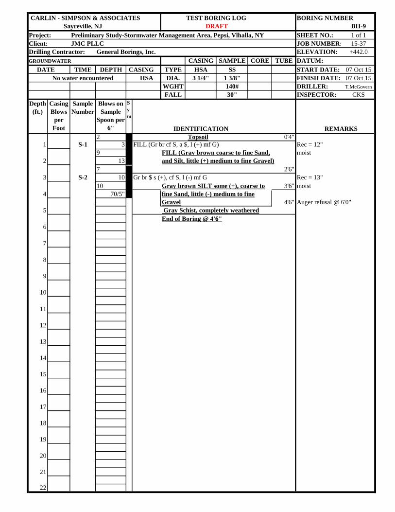
CARLIN - SIMPSON & ASSOCIATES TEST BORING LOG BORING NUMBERSayreville, NJ BH-9
Project: Preliminary Study-Stormwater Management Area, Pepsi, Vlhalla, NY SHEET NO.: 1 of 1Client: JMC PLLC JOB NUMBER: 15-37Drilling Contractor: General Borings, Inc. ELEVATION: +442.0GROUNDWATER CASING SAMPLE CORE TUBE DATUM: DATE TIME DEPTH CASING TYPE HSA SS START DATE: 07 Oct 15
No water encountered HSA DIA. 3 1/4" 1 3/8" FINISH DATE: 07 Oct 15WGHT 140# DRILLER: T.McGovernFALL 30" INSPECTOR: CKS
Depth (ft.)
Casing Blows
per Foot
Sample Number
Blows on Sample
Spoon per 6"
Sym
IDENTIFICATION REMARKS2 Topsoil 0'4"
1 S-1 3 FILL (Gr br cf S, a $, l (+) mf G) Rec = 12"9 FILL (Gray brown coarse to fine Sand, moist
2 13 and Silt, little (+) medium to fine Gravel)7 2'6"
3 S-2 10 Gr br $ s (+), cf S, l (-) mf G Rec = 13"10 Gray brown SILT some (+), coarse to 3'6" moist
4 70/5" fine Sand, little (-) medium to fineGravel 4'6" Auger refusal @ 6'0"
5 Gray Schist, completely weatheredEnd of Boring @ 4'6"
6
7
8
9
10
11
12
13
14
15
16
17
18
19
20
21
22
DRAFT
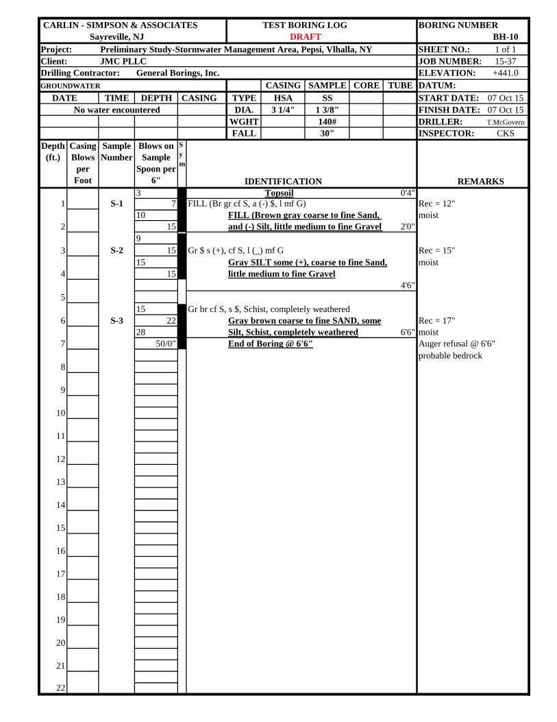
CARLIN - SIMPSON & ASSOCIATES TEST BORING LOG BORING NUMBERSayreville, NJ BH-10
Project: Preliminary Study-Stormwater Management Area, Pepsi, Vlhalla, NY SHEET NO.: 1 of 1Client: JMC PLLC JOB NUMBER: 15-37Drilling Contractor: General Borings, Inc. ELEVATION: +441.0GROUNDWATER CASING SAMPLE CORE TUBE DATUM: DATE TIME DEPTH CASING TYPE HSA SS START DATE: 07 Oct 15
No water encountered DIA. 3 1/4" 1 3/8" FINISH DATE: 07 Oct 15WGHT 140# DRILLER: T.McGovernFALL 30" INSPECTOR: CKS
Depth (ft.)
Casing Blows
per Foot
Sample Number
Blows on Sample
Spoon per 6"
Sym
IDENTIFICATION REMARKS3 Topsoil 0'4"
1 S-1 7 FILL (Br gr cf S, a (-) $, l mf G) Rec = 12"10 FILL (Brown gray coarse to fine Sand, moist
2 15 and (-) Silt, little medium to fine Gravel) 2'0"9
3 S-2 15 Gr $ s (+), cf S, l (_) mf G Rec = 15"15 Gray SILT some (+), coarse to fine Sand, moist
4 15 little medium to fine Gravel4'6"
515 Gr br cf S, s $, Schist, completely weathered
6 S-3 22 Gray brown coarse to fine SAND, some Rec = 17"28 Silt, Schist, completely weathered 6'6" moist
7 50/0" End of Boring @ 6'6" Auger refusal @ 6'6"probable bedrock
8
9
10
11
12
13
14
15
16
17
18
19
20
21
22
DRAFT
APPENDIX D
NATURAL RESOURCE DATA
1. Wetland Delineation Report, dated May 24, 2016,
by Evans Associates Environmental Consulting
2. USFWS National Wetlands Inventory mapping
3. NY Natural Heritage Program Rare Species /
Significant Natural Communities Documentation
4. Tree Inventory / Density Factor calculation
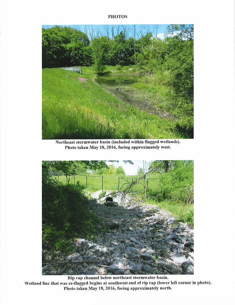
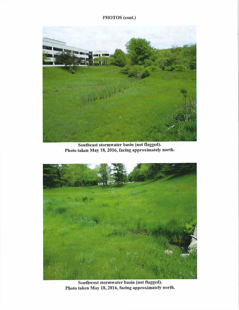
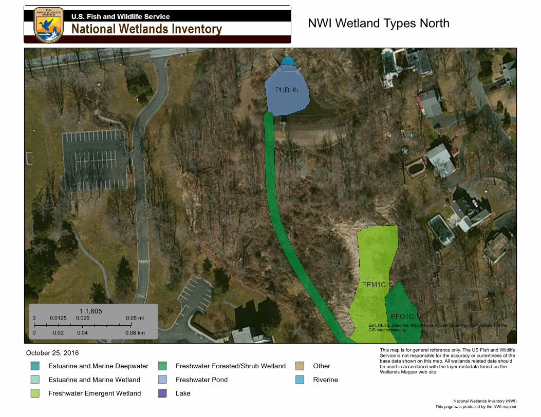
NWI Wetland Types North
Esri, HERE, DeLorme, MapmyIndia, © OpenStreetMap contributors, and theGIS user community
Estuarine and Marine DeepwaterEstuarine and Marine WetlandFreshwater Emergent Wetland
Freshwater Forested/Shrub WetlandFreshwater PondLake
OtherRiverine
October 25, 2016
0 0.025 0.050.0125 mi
0 0.04 0.080.02 km
1:1,605
This page was produced by the NWI mapperNational Wetlands Inventory (NWI)
This map is for general reference only. The US Fish and Wildlife Service is not responsible for the accuracy or currentness of the base data shown on this map. All wetlands related data should be used in accordance with the layer metadata found on the Wetlands Mapper web site.
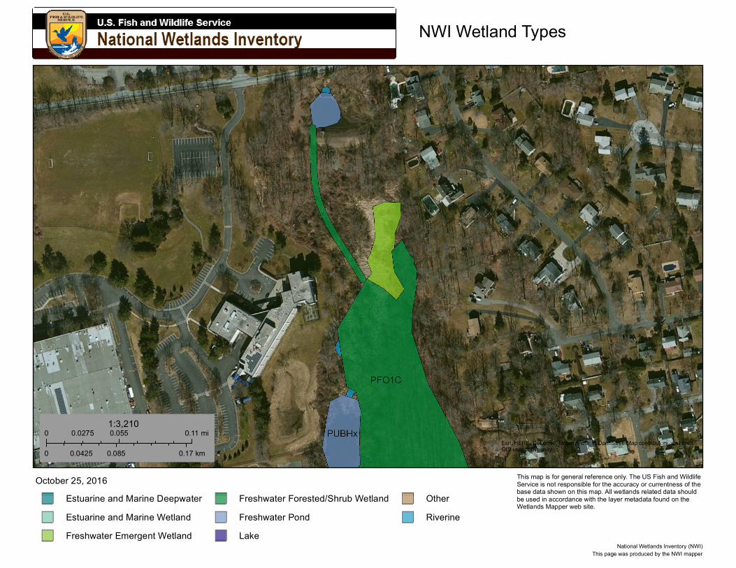
NWI Wetland Types
Esri, HERE, DeLorme, MapmyIndia, © OpenStreetMap contributors, and theGIS user community
Estuarine and Marine DeepwaterEstuarine and Marine WetlandFreshwater Emergent Wetland
Freshwater Forested/Shrub WetlandFreshwater PondLake
OtherRiverine
October 25, 2016
0 0.055 0.110.0275 mi
0 0.085 0.170.0425 km
1:3,210
This page was produced by the NWI mapperNational Wetlands Inventory (NWI)
This map is for general reference only. The US Fish and Wildlife Service is not responsible for the accuracy or currentness of the base data shown on this map. All wetlands related data should be used in accordance with the layer metadata found on the Wetlands Mapper web site.
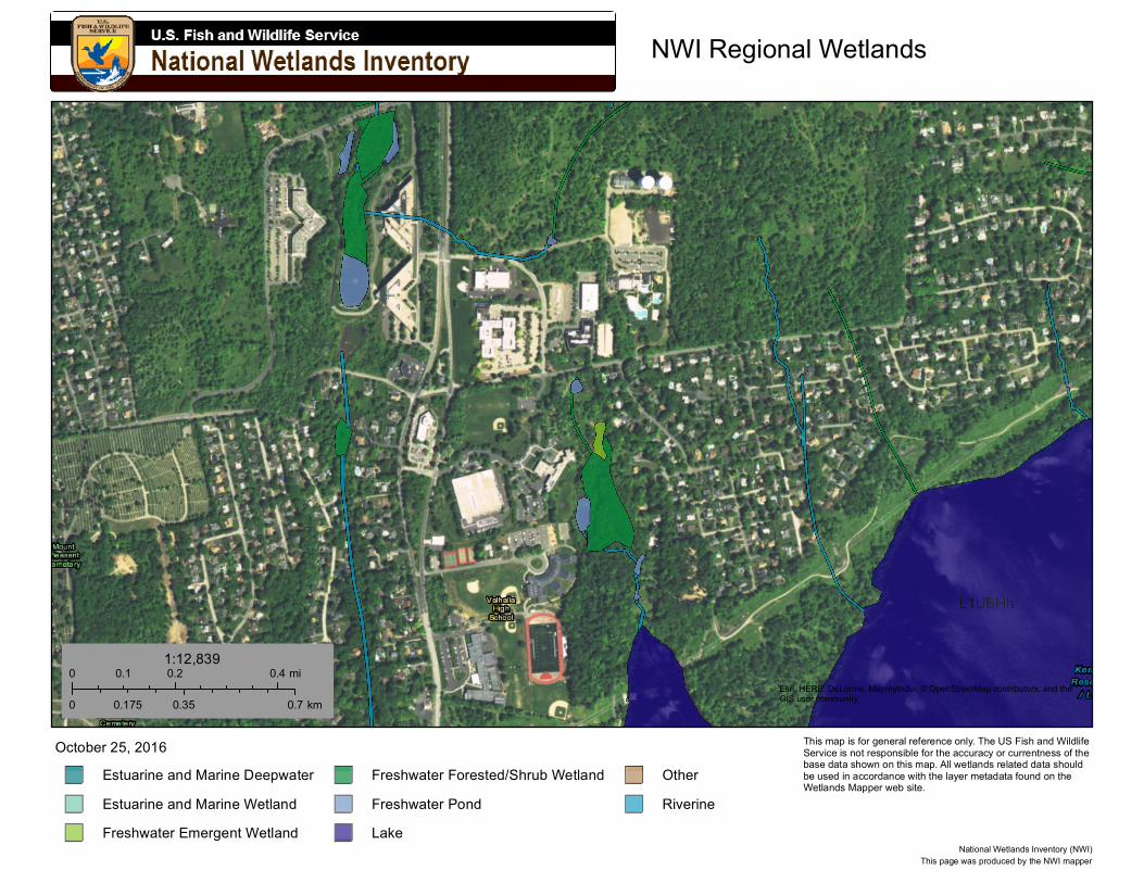
NWI Regional Wetlands
Esri, HERE, DeLorme, MapmyIndia, © OpenStreetMap contributors, and theGIS user community
Estuarine and Marine DeepwaterEstuarine and Marine WetlandFreshwater Emergent Wetland
Freshwater Forested/Shrub WetlandFreshwater PondLake
OtherRiverine
October 25, 2016
0 0.2 0.40.1 mi
0 0.35 0.70.175 km
1:12,839
This page was produced by the NWI mapperNational Wetlands Inventory (NWI)
This map is for general reference only. The US Fish and Wildlife Service is not responsible for the accuracy or currentness of the base data shown on this map. All wetlands related data should be used in accordance with the layer metadata found on the Wetlands Mapper web site.
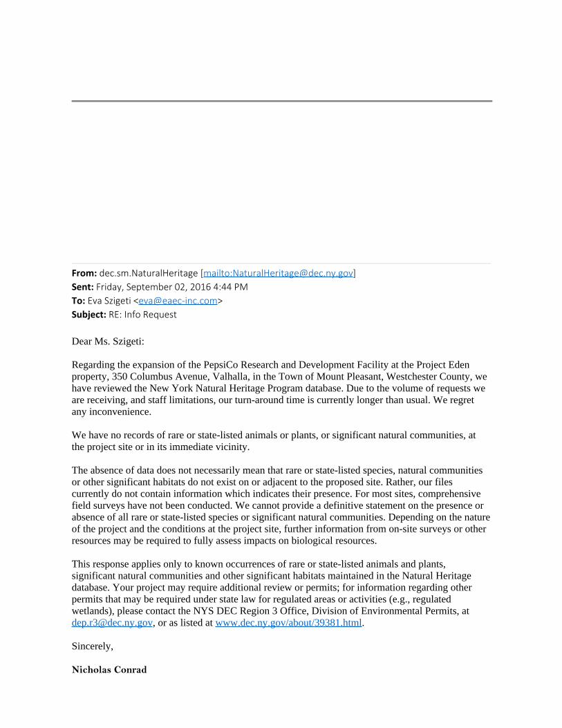
From: dec.sm.NaturalHeritage [mailto:[email protected]] Sent: Friday, September 02, 2016 4:44 PMTo: Eva Szigeti <[email protected]>Subject: RE: Info Request
Dear Ms. Szigeti:
Regarding the expansion of the PepsiCo Research and Development Facility at the Project Edenproperty, 350 Columbus Avenue, Valhalla, in the Town of Mount Pleasant, Westchester County, wehave reviewed the New York Natural Heritage Program database. Due to the volume of requests weare receiving, and staff limitations, our turn-around time is currently longer than usual. We regretany inconvenience.
We have no records of rare or state-listed animals or plants, or significant natural communities, atthe project site or in its immediate vicinity.
The absence of data does not necessarily mean that rare or state-listed species, natural communitiesor other significant habitats do not exist on or adjacent to the proposed site. Rather, our filescurrently do not contain information which indicates their presence. For most sites, comprehensivefield surveys have not been conducted. We cannot provide a definitive statement on the presence orabsence of all rare or state-listed species or significant natural communities. Depending on the natureof the project and the conditions at the project site, further information from on-site surveys or otherresources may be required to fully assess impacts on biological resources.
This response applies only to known occurrences of rare or state-listed animals and plants,significant natural communities and other significant habitats maintained in the Natural Heritagedatabase. Your project may require additional review or permits; for information regarding otherpermits that may be required under state law for regulated areas or activities (e.g., regulatedwetlands), please contact the NYS DEC Region 3 Office, Division of Environmental Permits, [email protected], or as listed at www.dec.ny.gov/about/39381.html.
Sincerely,
Nicholas Conrad

Information Resources CoordinatorNew York Natural Heritage ProgramSUNY College of Environmental Science and ForestryIn partnership with NYS Department of Environmental Conservation625 BroadwayAlbany, NY 12233-4757(518) 402-8935www.nynhp.org
From: Eva Szigeti [mailto:[email protected]] Sent: Friday, July 29, 2016 12:14 PMTo: dec.sm.NaturalHeritage <[email protected]>Subject: Info Request Eva Szigeti, CPSSEvans Associates Environmental Consulting, Inc.205 Amity Road, Bethany CT 06524phone: 203 393 0690 fax: 203 393 0196
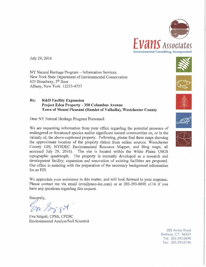
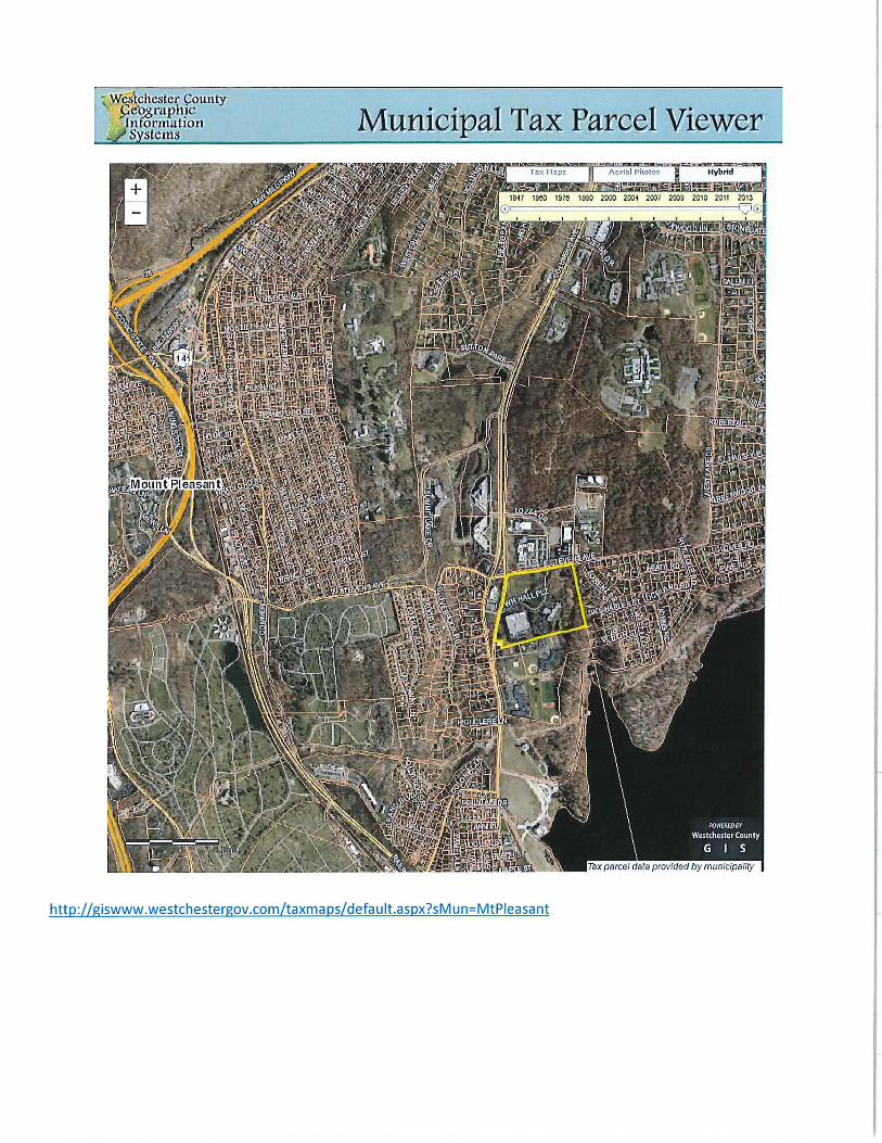
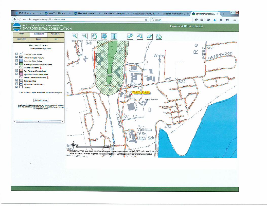
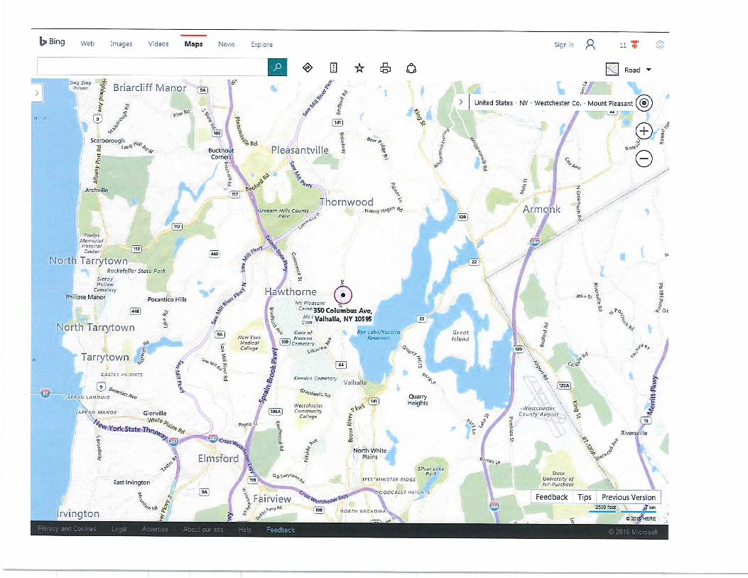
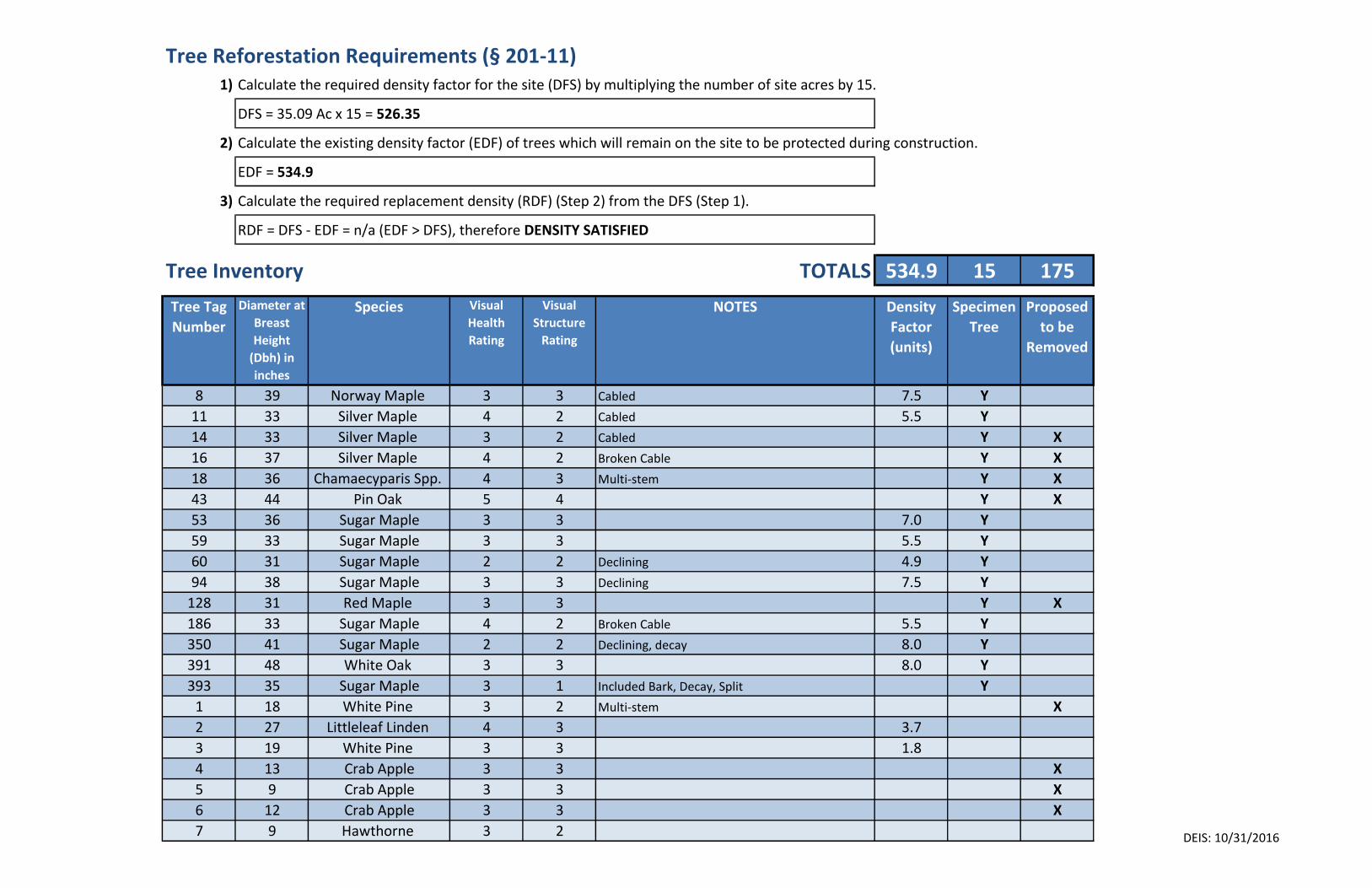
Tree Reforestation Requirements (§ 201-11)1) Calculate the required density factor for the site (DFS) by multiplying the number of site acres by 15.
DFS = 35.09 Ac x 15 = 526.35
2) Calculate the existing density factor (EDF) of trees which will remain on the site to be protected during construction.
EDF = 534.9
3) Calculate the required replacement density (RDF) (Step 2) from the DFS (Step 1).
RDF = DFS - EDF = n/a (EDF > DFS), therefore DENSITY SATISFIED
Tree Inventory TOTALS 534.9 15 175
Tree Tag
Number
Diameter at
Breast
Height
(Dbh) in
inches
Species Visual
Health
Rating
Visual
Structure
Rating
NOTES Density
Factor
(units)
Specimen
Tree
Proposed
to be
Removed
8 39 Norway Maple 3 3 Cabled 7.5 Y
11 33 Silver Maple 4 2 Cabled 5.5 Y
14 33 Silver Maple 3 2 Cabled Y X
16 37 Silver Maple 4 2 Broken Cable Y X
18 36 Chamaecyparis Spp. 4 3 Multi-stem Y X
43 44 Pin Oak 5 4 Y X
53 36 Sugar Maple 3 3 7.0 Y
59 33 Sugar Maple 3 3 5.5 Y
60 31 Sugar Maple 2 2 Declining 4.9 Y
94 38 Sugar Maple 3 3 Declining 7.5 Y
128 31 Red Maple 3 3 Y X
186 33 Sugar Maple 4 2 Broken Cable 5.5 Y
350 41 Sugar Maple 2 2 Declining, decay 8.0 Y
391 48 White Oak 3 3 8.0 Y
393 35 Sugar Maple 3 1 Included Bark, Decay, Split Y
1 18 White Pine 3 2 Multi-stem X
2 27 Littleleaf Linden 4 3 3.7
3 19 White Pine 3 3 1.8
4 13 Crab Apple 3 3 X
5 9 Crab Apple 3 3 X
6 12 Crab Apple 3 3 X
7 9 Hawthorne 3 2 DEIS: 10/31/2016
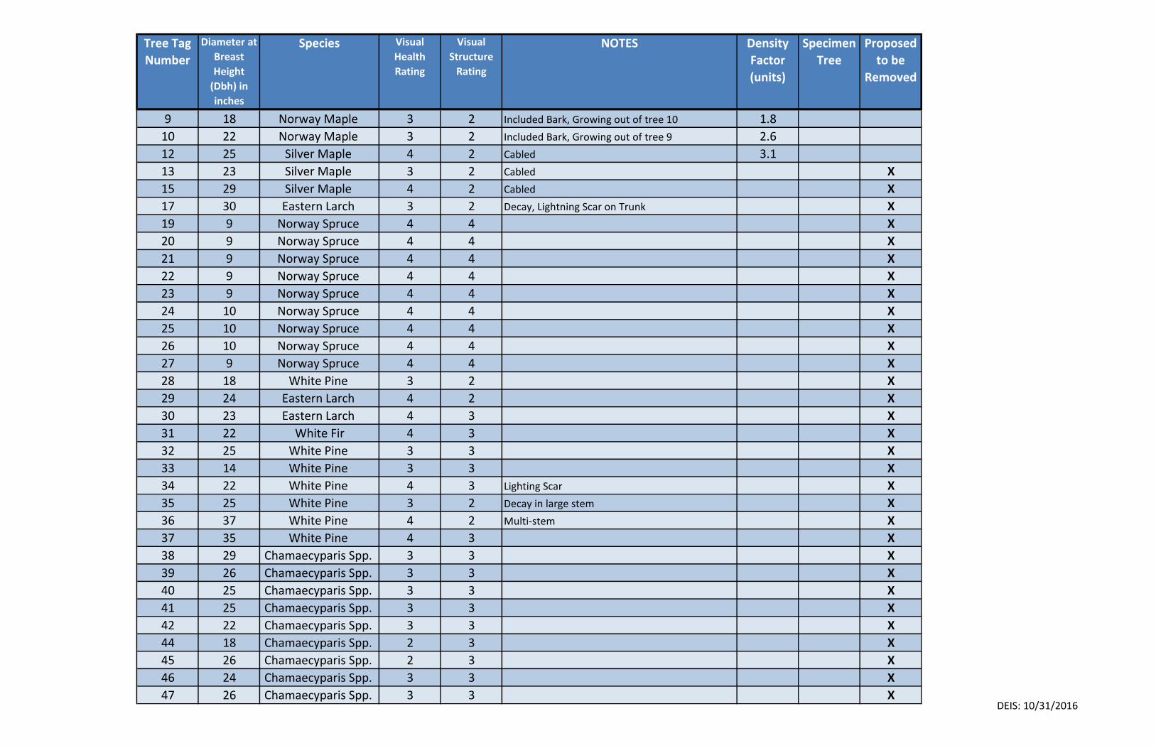
Tree Tag
Number
Diameter at
Breast
Height
(Dbh) in
inches
Species Visual
Health
Rating
Visual
Structure
Rating
NOTES Density
Factor
(units)
Specimen
Tree
Proposed
to be
Removed
9 18 Norway Maple 3 2 Included Bark, Growing out of tree 10 1.8
10 22 Norway Maple 3 2 Included Bark, Growing out of tree 9 2.6
12 25 Silver Maple 4 2 Cabled 3.1
13 23 Silver Maple 3 2 Cabled X
15 29 Silver Maple 4 2 Cabled X
17 30 Eastern Larch 3 2 Decay, Lightning Scar on Trunk X
19 9 Norway Spruce 4 4 X
20 9 Norway Spruce 4 4 X
21 9 Norway Spruce 4 4 X
22 9 Norway Spruce 4 4 X
23 9 Norway Spruce 4 4 X
24 10 Norway Spruce 4 4 X
25 10 Norway Spruce 4 4 X
26 10 Norway Spruce 4 4 X
27 9 Norway Spruce 4 4 X
28 18 White Pine 3 2 X
29 24 Eastern Larch 4 2 X
30 23 Eastern Larch 4 3 X
31 22 White Fir 4 3 X
32 25 White Pine 3 3 X
33 14 White Pine 3 3 X
34 22 White Pine 4 3 Lighting Scar X
35 25 White Pine 3 2 Decay in large stem X
36 37 White Pine 4 2 Multi-stem X
37 35 White Pine 4 3 X
38 29 Chamaecyparis Spp. 3 3 X
39 26 Chamaecyparis Spp. 3 3 X
40 25 Chamaecyparis Spp. 3 3 X
41 25 Chamaecyparis Spp. 3 3 X
42 22 Chamaecyparis Spp. 3 3 X
44 18 Chamaecyparis Spp. 2 3 X
45 26 Chamaecyparis Spp. 2 3 X
46 24 Chamaecyparis Spp. 3 3 X
47 26 Chamaecyparis Spp. 3 3 XDEIS: 10/31/2016
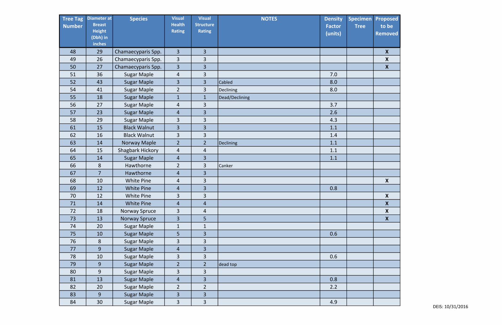
Tree Tag
Number
Diameter at
Breast
Height
(Dbh) in
inches
Species Visual
Health
Rating
Visual
Structure
Rating
NOTES Density
Factor
(units)
Specimen
Tree
Proposed
to be
Removed
48 29 Chamaecyparis Spp. 3 3 X
49 26 Chamaecyparis Spp. 3 3 X
50 27 Chamaecyparis Spp. 3 3 X
51 36 Sugar Maple 4 3 7.0
52 43 Sugar Maple 3 3 Cabled 8.0
54 41 Sugar Maple 2 3 Declining 8.0
55 18 Sugar Maple 1 1 Dead/Declining
56 27 Sugar Maple 4 3 3.7
57 23 Sugar Maple 4 3 2.6
58 29 Sugar Maple 3 3 4.3
61 15 Black Walnut 3 3 1.1
62 16 Black Walnut 3 3 1.4
63 14 Norway Maple 2 2 Declining 1.1
64 15 Shagbark Hickory 4 4 1.1
65 14 Sugar Maple 4 3 1.1
66 8 Hawthorne 2 3 Canker
67 7 Hawthorne 4 3
68 10 White Pine 4 3 X
69 12 White Pine 4 3 0.8
70 12 White Pine 3 3 X
71 14 White Pine 4 4 X
72 18 Norway Spruce 3 4 X
73 13 Norway Spruce 3 5 X
74 20 Sugar Maple 1 1
75 10 Sugar Maple 5 3 0.6
76 8 Sugar Maple 3 3
77 9 Sugar Maple 4 3
78 10 Sugar Maple 3 3 0.6
79 9 Sugar Maple 2 2 dead top
80 9 Sugar Maple 3 3
81 13 Sugar Maple 4 3 0.8
82 20 Sugar Maple 2 2 2.2
83 9 Sugar Maple 3 3
84 30 Sugar Maple 3 3 4.9DEIS: 10/31/2016
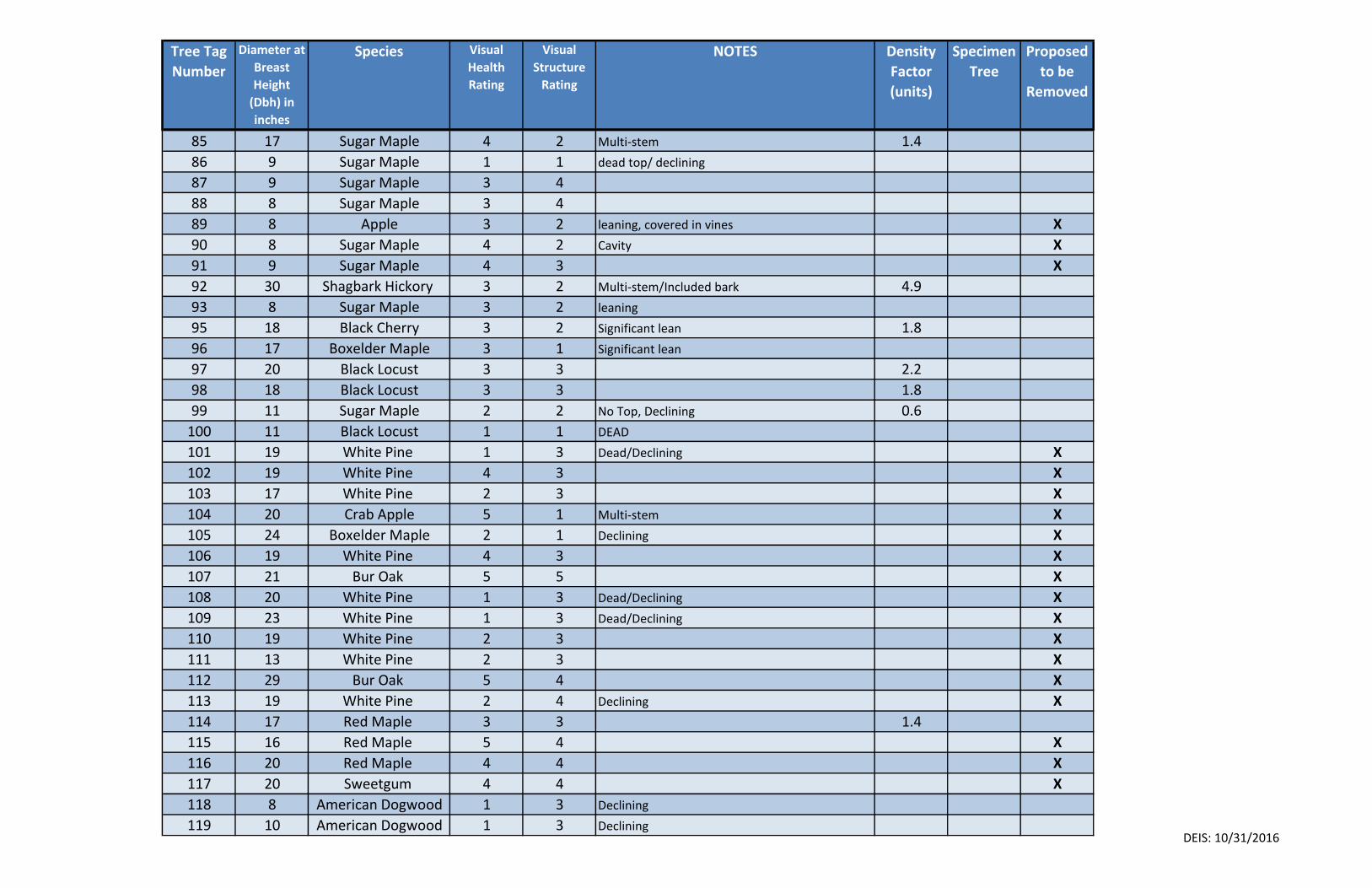
Tree Tag
Number
Diameter at
Breast
Height
(Dbh) in
inches
Species Visual
Health
Rating
Visual
Structure
Rating
NOTES Density
Factor
(units)
Specimen
Tree
Proposed
to be
Removed
85 17 Sugar Maple 4 2 Multi-stem 1.4
86 9 Sugar Maple 1 1 dead top/ declining
87 9 Sugar Maple 3 4
88 8 Sugar Maple 3 4
89 8 Apple 3 2 leaning, covered in vines X
90 8 Sugar Maple 4 2 Cavity X
91 9 Sugar Maple 4 3 X
92 30 Shagbark Hickory 3 2 Multi-stem/Included bark 4.9
93 8 Sugar Maple 3 2 leaning
95 18 Black Cherry 3 2 Significant lean 1.8
96 17 Boxelder Maple 3 1 Significant lean
97 20 Black Locust 3 3 2.2
98 18 Black Locust 3 3 1.8
99 11 Sugar Maple 2 2 No Top, Declining 0.6
100 11 Black Locust 1 1 DEAD
101 19 White Pine 1 3 Dead/Declining X
102 19 White Pine 4 3 X
103 17 White Pine 2 3 X
104 20 Crab Apple 5 1 Multi-stem X
105 24 Boxelder Maple 2 1 Declining X
106 19 White Pine 4 3 X
107 21 Bur Oak 5 5 X
108 20 White Pine 1 3 Dead/Declining X
109 23 White Pine 1 3 Dead/Declining X
110 19 White Pine 2 3 X
111 13 White Pine 2 3 X
112 29 Bur Oak 5 4 X
113 19 White Pine 2 4 Declining X
114 17 Red Maple 3 3 1.4
115 16 Red Maple 5 4 X
116 20 Red Maple 4 4 X
117 20 Sweetgum 4 4 X
118 8 American Dogwood 1 3 Declining
119 10 American Dogwood 1 3 Declining DEIS: 10/31/2016
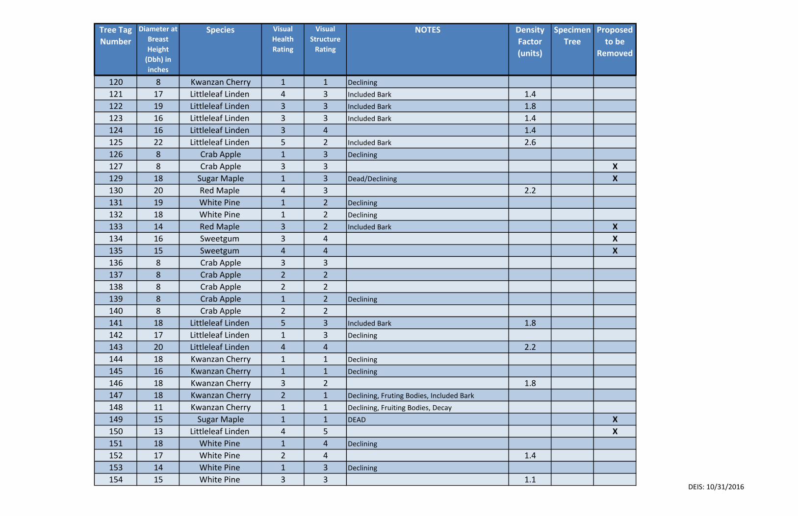
Tree Tag
Number
Diameter at
Breast
Height
(Dbh) in
inches
Species Visual
Health
Rating
Visual
Structure
Rating
NOTES Density
Factor
(units)
Specimen
Tree
Proposed
to be
Removed
120 8 Kwanzan Cherry 1 1 Declining
121 17 Littleleaf Linden 4 3 Included Bark 1.4
122 19 Littleleaf Linden 3 3 Included Bark 1.8
123 16 Littleleaf Linden 3 3 Included Bark 1.4
124 16 Littleleaf Linden 3 4 1.4
125 22 Littleleaf Linden 5 2 Included Bark 2.6
126 8 Crab Apple 1 3 Declining
127 8 Crab Apple 3 3 X
129 18 Sugar Maple 1 3 Dead/Declining X
130 20 Red Maple 4 3 2.2
131 19 White Pine 1 2 Declining
132 18 White Pine 1 2 Declining
133 14 Red Maple 3 2 Included Bark X
134 16 Sweetgum 3 4 X
135 15 Sweetgum 4 4 X
136 8 Crab Apple 3 3
137 8 Crab Apple 2 2
138 8 Crab Apple 2 2
139 8 Crab Apple 1 2 Declining
140 8 Crab Apple 2 2
141 18 Littleleaf Linden 5 3 Included Bark 1.8
142 17 Littleleaf Linden 1 3 Declining
143 20 Littleleaf Linden 4 4 2.2
144 18 Kwanzan Cherry 1 1 Declining
145 16 Kwanzan Cherry 1 1 Declining
146 18 Kwanzan Cherry 3 2 1.8
147 18 Kwanzan Cherry 2 1 Declining, Fruting Bodies, Included Bark
148 11 Kwanzan Cherry 1 1 Declining, Fruiting Bodies, Decay
149 15 Sugar Maple 1 1 DEAD X
150 13 Littleleaf Linden 4 5 X
151 18 White Pine 1 4 Declining
152 17 White Pine 2 4 1.4
153 14 White Pine 1 3 Declining
154 15 White Pine 3 3 1.1DEIS: 10/31/2016
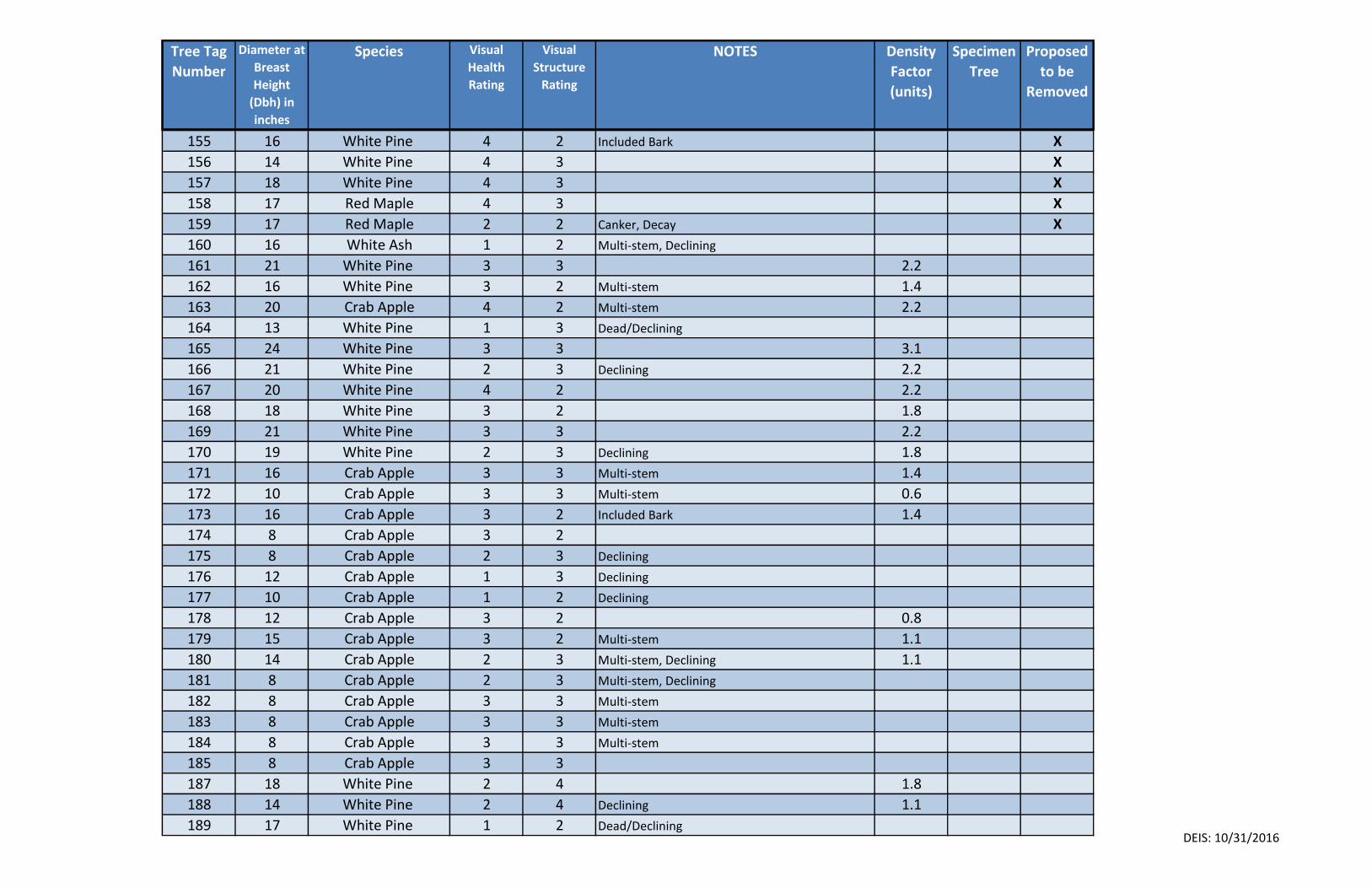
Tree Tag
Number
Diameter at
Breast
Height
(Dbh) in
inches
Species Visual
Health
Rating
Visual
Structure
Rating
NOTES Density
Factor
(units)
Specimen
Tree
Proposed
to be
Removed
155 16 White Pine 4 2 Included Bark X
156 14 White Pine 4 3 X
157 18 White Pine 4 3 X
158 17 Red Maple 4 3 X
159 17 Red Maple 2 2 Canker, Decay X
160 16 White Ash 1 2 Multi-stem, Declining
161 21 White Pine 3 3 2.2
162 16 White Pine 3 2 Multi-stem 1.4
163 20 Crab Apple 4 2 Multi-stem 2.2
164 13 White Pine 1 3 Dead/Declining
165 24 White Pine 3 3 3.1
166 21 White Pine 2 3 Declining 2.2
167 20 White Pine 4 2 2.2
168 18 White Pine 3 2 1.8
169 21 White Pine 3 3 2.2
170 19 White Pine 2 3 Declining 1.8
171 16 Crab Apple 3 3 Multi-stem 1.4
172 10 Crab Apple 3 3 Multi-stem 0.6
173 16 Crab Apple 3 2 Included Bark 1.4
174 8 Crab Apple 3 2
175 8 Crab Apple 2 3 Declining
176 12 Crab Apple 1 3 Declining
177 10 Crab Apple 1 2 Declining
178 12 Crab Apple 3 2 0.8
179 15 Crab Apple 3 2 Multi-stem 1.1
180 14 Crab Apple 2 3 Multi-stem, Declining 1.1
181 8 Crab Apple 2 3 Multi-stem, Declining
182 8 Crab Apple 3 3 Multi-stem
183 8 Crab Apple 3 3 Multi-stem
184 8 Crab Apple 3 3 Multi-stem
185 8 Crab Apple 3 3
187 18 White Pine 2 4 1.8
188 14 White Pine 2 4 Declining 1.1
189 17 White Pine 1 2 Dead/Declining DEIS: 10/31/2016
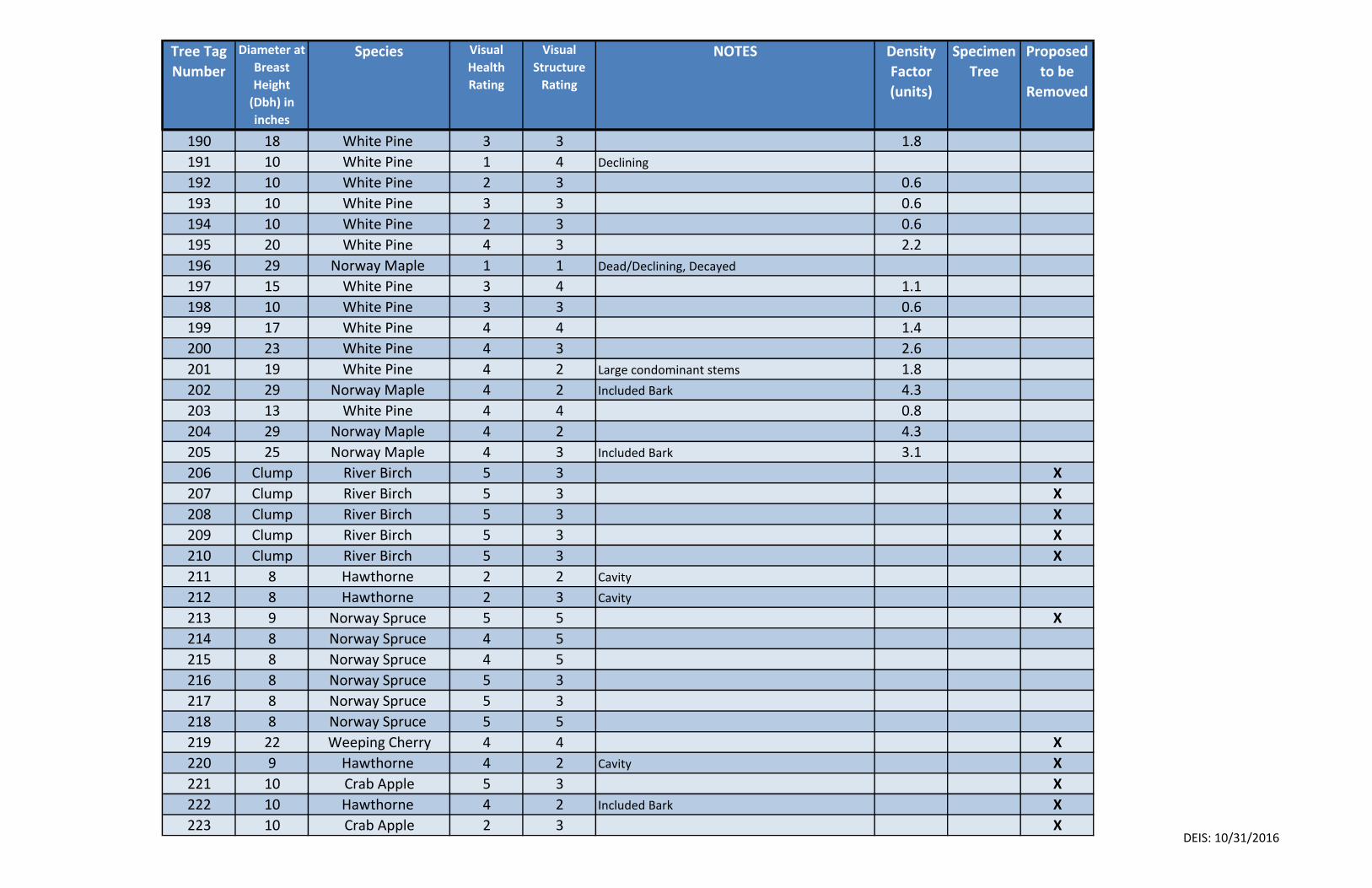
Tree Tag
Number
Diameter at
Breast
Height
(Dbh) in
inches
Species Visual
Health
Rating
Visual
Structure
Rating
NOTES Density
Factor
(units)
Specimen
Tree
Proposed
to be
Removed
190 18 White Pine 3 3 1.8
191 10 White Pine 1 4 Declining
192 10 White Pine 2 3 0.6
193 10 White Pine 3 3 0.6
194 10 White Pine 2 3 0.6
195 20 White Pine 4 3 2.2
196 29 Norway Maple 1 1 Dead/Declining, Decayed
197 15 White Pine 3 4 1.1
198 10 White Pine 3 3 0.6
199 17 White Pine 4 4 1.4
200 23 White Pine 4 3 2.6
201 19 White Pine 4 2 Large condominant stems 1.8
202 29 Norway Maple 4 2 Included Bark 4.3
203 13 White Pine 4 4 0.8
204 29 Norway Maple 4 2 4.3
205 25 Norway Maple 4 3 Included Bark 3.1
206 Clump River Birch 5 3 X
207 Clump River Birch 5 3 X
208 Clump River Birch 5 3 X
209 Clump River Birch 5 3 X
210 Clump River Birch 5 3 X
211 8 Hawthorne 2 2 Cavity
212 8 Hawthorne 2 3 Cavity
213 9 Norway Spruce 5 5 X
214 8 Norway Spruce 4 5
215 8 Norway Spruce 4 5
216 8 Norway Spruce 5 3
217 8 Norway Spruce 5 3
218 8 Norway Spruce 5 5
219 22 Weeping Cherry 4 4 X
220 9 Hawthorne 4 2 Cavity X
221 10 Crab Apple 5 3 X
222 10 Hawthorne 4 2 Included Bark X
223 10 Crab Apple 2 3 XDEIS: 10/31/2016
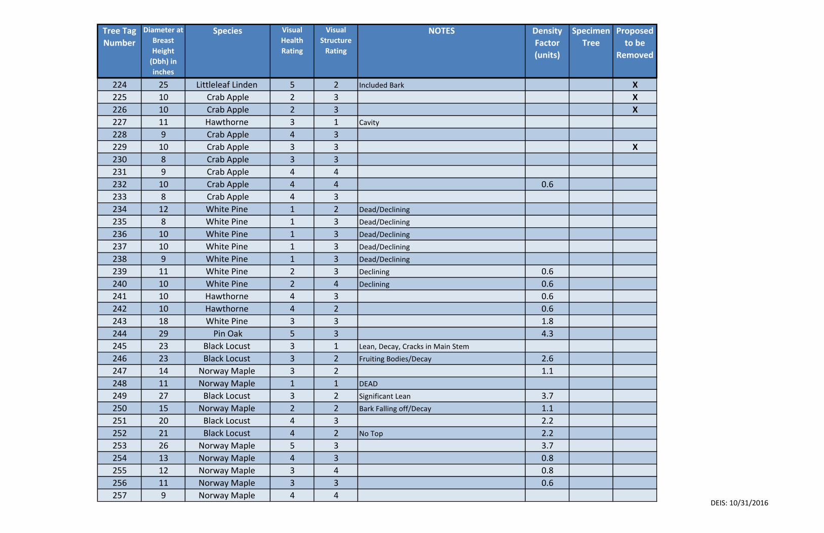
Tree Tag
Number
Diameter at
Breast
Height
(Dbh) in
inches
Species Visual
Health
Rating
Visual
Structure
Rating
NOTES Density
Factor
(units)
Specimen
Tree
Proposed
to be
Removed
224 25 Littleleaf Linden 5 2 Included Bark X
225 10 Crab Apple 2 3 X
226 10 Crab Apple 2 3 X
227 11 Hawthorne 3 1 Cavity
228 9 Crab Apple 4 3
229 10 Crab Apple 3 3 X
230 8 Crab Apple 3 3
231 9 Crab Apple 4 4
232 10 Crab Apple 4 4 0.6
233 8 Crab Apple 4 3
234 12 White Pine 1 2 Dead/Declining
235 8 White Pine 1 3 Dead/Declining
236 10 White Pine 1 3 Dead/Declining
237 10 White Pine 1 3 Dead/Declining
238 9 White Pine 1 3 Dead/Declining
239 11 White Pine 2 3 Declining 0.6
240 10 White Pine 2 4 Declining 0.6
241 10 Hawthorne 4 3 0.6
242 10 Hawthorne 4 2 0.6
243 18 White Pine 3 3 1.8
244 29 Pin Oak 5 3 4.3
245 23 Black Locust 3 1 Lean, Decay, Cracks in Main Stem
246 23 Black Locust 3 2 Fruiting Bodies/Decay 2.6
247 14 Norway Maple 3 2 1.1
248 11 Norway Maple 1 1 DEAD
249 27 Black Locust 3 2 Significant Lean 3.7
250 15 Norway Maple 2 2 Bark Falling off/Decay 1.1
251 20 Black Locust 4 3 2.2
252 21 Black Locust 4 2 No Top 2.2
253 26 Norway Maple 5 3 3.7
254 13 Norway Maple 4 3 0.8
255 12 Norway Maple 3 4 0.8
256 11 Norway Maple 3 3 0.6
257 9 Norway Maple 4 4DEIS: 10/31/2016
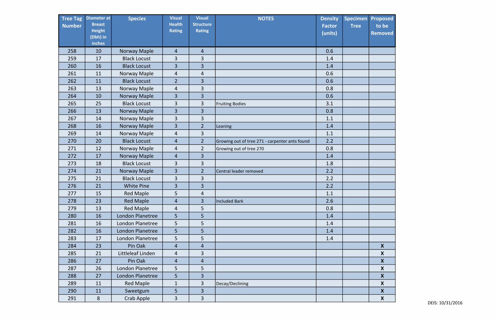
Tree Tag
Number
Diameter at
Breast
Height
(Dbh) in
inches
Species Visual
Health
Rating
Visual
Structure
Rating
NOTES Density
Factor
(units)
Specimen
Tree
Proposed
to be
Removed
258 10 Norway Maple 4 4 0.6
259 17 Black Locust 3 3 1.4
260 16 Black Locust 3 3 1.4
261 11 Norway Maple 4 4 0.6
262 11 Black Locust 2 3 0.6
263 13 Norway Maple 4 3 0.8
264 10 Norway Maple 3 3 0.6
265 25 Black Locust 3 3 Fruiting Bodies 3.1
266 13 Norway Maple 3 3 0.8
267 14 Norway Maple 3 3 1.1
268 16 Norway Maple 3 2 Leaning 1.4
269 14 Norway Maple 4 3 1.1
270 20 Black Locust 4 2 Growing out of tree 271 - carpenter ants found 2.2
271 12 Norway Maple 4 2 Growing out of tree 270 0.8
272 17 Norway Maple 4 3 1.4
273 18 Black Locust 3 3 1.8
274 21 Norway Maple 3 2 Central leader removed 2.2
275 21 Black Locust 3 3 2.2
276 21 White Pine 3 3 2.2
277 15 Red Maple 5 4 1.1
278 23 Red Maple 4 3 Included Bark 2.6
279 13 Red Maple 4 5 0.8
280 16 London Planetree 5 5 1.4
281 16 London Planetree 5 5 1.4
282 16 London Planetree 5 5 1.4
283 17 London Planetree 5 5 1.4
284 23 Pin Oak 4 4 X
285 21 Littleleaf Linden 4 3 X
286 27 Pin Oak 4 4 X
287 26 London Planetree 5 5 X
288 27 London Planetree 5 3 X
289 11 Red Maple 1 3 Decay/Declining X
290 11 Sweetgum 5 3 X
291 8 Crab Apple 3 3 XDEIS: 10/31/2016
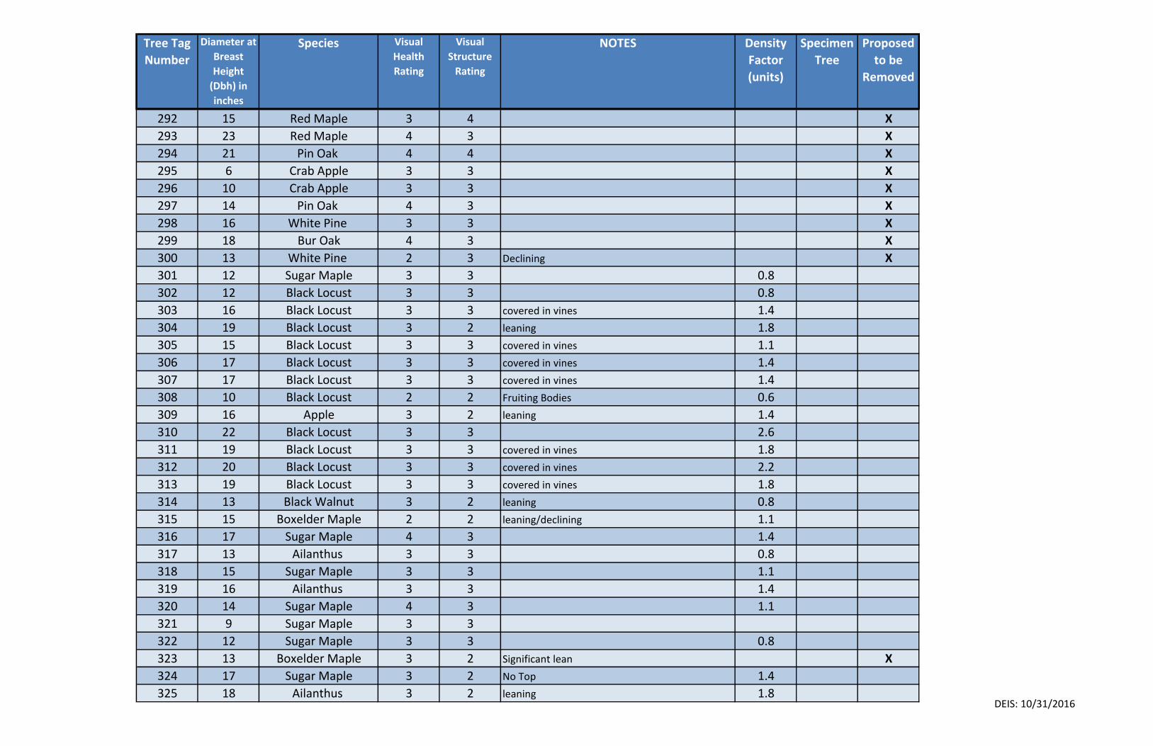
Tree Tag
Number
Diameter at
Breast
Height
(Dbh) in
inches
Species Visual
Health
Rating
Visual
Structure
Rating
NOTES Density
Factor
(units)
Specimen
Tree
Proposed
to be
Removed
292 15 Red Maple 3 4 X
293 23 Red Maple 4 3 X
294 21 Pin Oak 4 4 X
295 6 Crab Apple 3 3 X
296 10 Crab Apple 3 3 X
297 14 Pin Oak 4 3 X
298 16 White Pine 3 3 X
299 18 Bur Oak 4 3 X
300 13 White Pine 2 3 Declining X
301 12 Sugar Maple 3 3 0.8
302 12 Black Locust 3 3 0.8
303 16 Black Locust 3 3 covered in vines 1.4
304 19 Black Locust 3 2 leaning 1.8
305 15 Black Locust 3 3 covered in vines 1.1
306 17 Black Locust 3 3 covered in vines 1.4
307 17 Black Locust 3 3 covered in vines 1.4
308 10 Black Locust 2 2 Fruiting Bodies 0.6
309 16 Apple 3 2 leaning 1.4
310 22 Black Locust 3 3 2.6
311 19 Black Locust 3 3 covered in vines 1.8
312 20 Black Locust 3 3 covered in vines 2.2
313 19 Black Locust 3 3 covered in vines 1.8
314 13 Black Walnut 3 2 leaning 0.8
315 15 Boxelder Maple 2 2 leaning/declining 1.1
316 17 Sugar Maple 4 3 1.4
317 13 Ailanthus 3 3 0.8
318 15 Sugar Maple 3 3 1.1
319 16 Ailanthus 3 3 1.4
320 14 Sugar Maple 4 3 1.1
321 9 Sugar Maple 3 3
322 12 Sugar Maple 3 3 0.8
323 13 Boxelder Maple 3 2 Significant lean X
324 17 Sugar Maple 3 2 No Top 1.4
325 18 Ailanthus 3 2 leaning 1.8DEIS: 10/31/2016
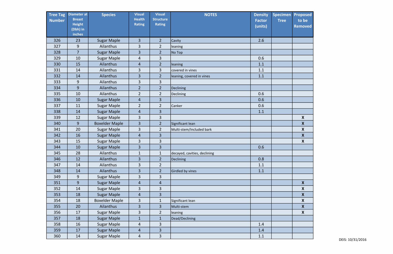
Tree Tag
Number
Diameter at
Breast
Height
(Dbh) in
inches
Species Visual
Health
Rating
Visual
Structure
Rating
NOTES Density
Factor
(units)
Specimen
Tree
Proposed
to be
Removed
326 23 Sugar Maple 3 2 Cavity 2.6
327 9 Ailanthus 3 2 leaning
328 7 Sugar Maple 3 2 No Top
329 10 Sugar Maple 4 3 0.6
330 15 Ailanthus 4 2 leaning 1.1
331 14 Ailanthus 3 3 covered in vines 1.1
332 14 Ailanthus 3 2 leaning, covered in vines 1.1
333 9 Ailanthus 3 3
334 9 Ailanthus 2 2 Declining
335 10 Ailanthus 2 2 Declining 0.6
336 10 Sugar Maple 4 3 0.6
337 11 Sugar Maple 2 2 Canker 0.6
338 14 Sugar Maple 4 3 1.1
339 12 Sugar Maple 3 3 X
340 9 Boxelder Maple 3 2 Significant lean X
341 20 Sugar Maple 3 2 Multi-stem/Included bark X
342 16 Sugar Maple 4 3 X
343 15 Sugar Maple 3 3 X
344 10 Sugar Maple 3 3 0.6
345 28 Ailanthus 1 1 decayed, cavities, declining
346 12 Ailanthus 3 2 Declining 0.8
347 14 Ailanthus 3 2 1.1
348 14 Ailanthus 3 2 Girdled by vines 1.1
349 9 Sugar Maple 3 3
351 9 Sugar Maple 4 4 X
352 14 Sugar Maple 3 3 X
353 18 Sugar Maple 4 3 X
354 18 Boxelder Maple 3 1 Significant lean X
355 20 Ailanthus 3 3 Multi-stem X
356 17 Sugar Maple 3 2 leaning X
357 18 Sugar Maple 1 1 Dead/Declining
358 16 Sugar Maple 4 3 1.4
359 17 Sugar Maple 4 3 1.4
360 14 Sugar Maple 4 3 1.1DEIS: 10/31/2016
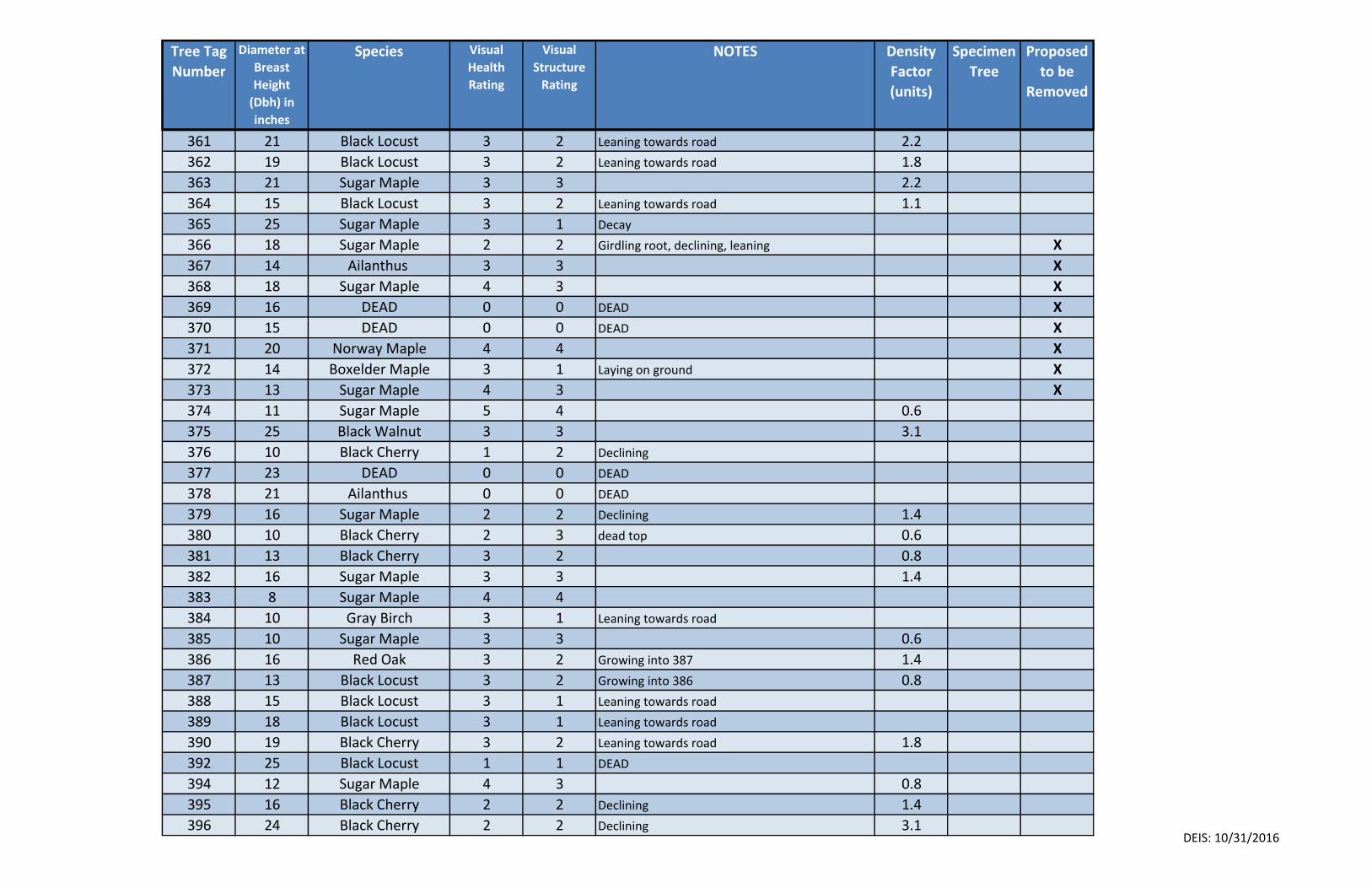
Tree Tag
Number
Diameter at
Breast
Height
(Dbh) in
inches
Species Visual
Health
Rating
Visual
Structure
Rating
NOTES Density
Factor
(units)
Specimen
Tree
Proposed
to be
Removed
361 21 Black Locust 3 2 Leaning towards road 2.2
362 19 Black Locust 3 2 Leaning towards road 1.8
363 21 Sugar Maple 3 3 2.2
364 15 Black Locust 3 2 Leaning towards road 1.1
365 25 Sugar Maple 3 1 Decay
366 18 Sugar Maple 2 2 Girdling root, declining, leaning X
367 14 Ailanthus 3 3 X
368 18 Sugar Maple 4 3 X
369 16 DEAD 0 0 DEAD X
370 15 DEAD 0 0 DEAD X
371 20 Norway Maple 4 4 X
372 14 Boxelder Maple 3 1 Laying on ground X
373 13 Sugar Maple 4 3 X
374 11 Sugar Maple 5 4 0.6
375 25 Black Walnut 3 3 3.1
376 10 Black Cherry 1 2 Declining
377 23 DEAD 0 0 DEAD
378 21 Ailanthus 0 0 DEAD
379 16 Sugar Maple 2 2 Declining 1.4
380 10 Black Cherry 2 3 dead top 0.6
381 13 Black Cherry 3 2 0.8
382 16 Sugar Maple 3 3 1.4
383 8 Sugar Maple 4 4
384 10 Gray Birch 3 1 Leaning towards road
385 10 Sugar Maple 3 3 0.6
386 16 Red Oak 3 2 Growing into 387 1.4
387 13 Black Locust 3 2 Growing into 386 0.8
388 15 Black Locust 3 1 Leaning towards road
389 18 Black Locust 3 1 Leaning towards road
390 19 Black Cherry 3 2 Leaning towards road 1.8
392 25 Black Locust 1 1 DEAD
394 12 Sugar Maple 4 3 0.8
395 16 Black Cherry 2 2 Declining 1.4
396 24 Black Cherry 2 2 Declining 3.1DEIS: 10/31/2016
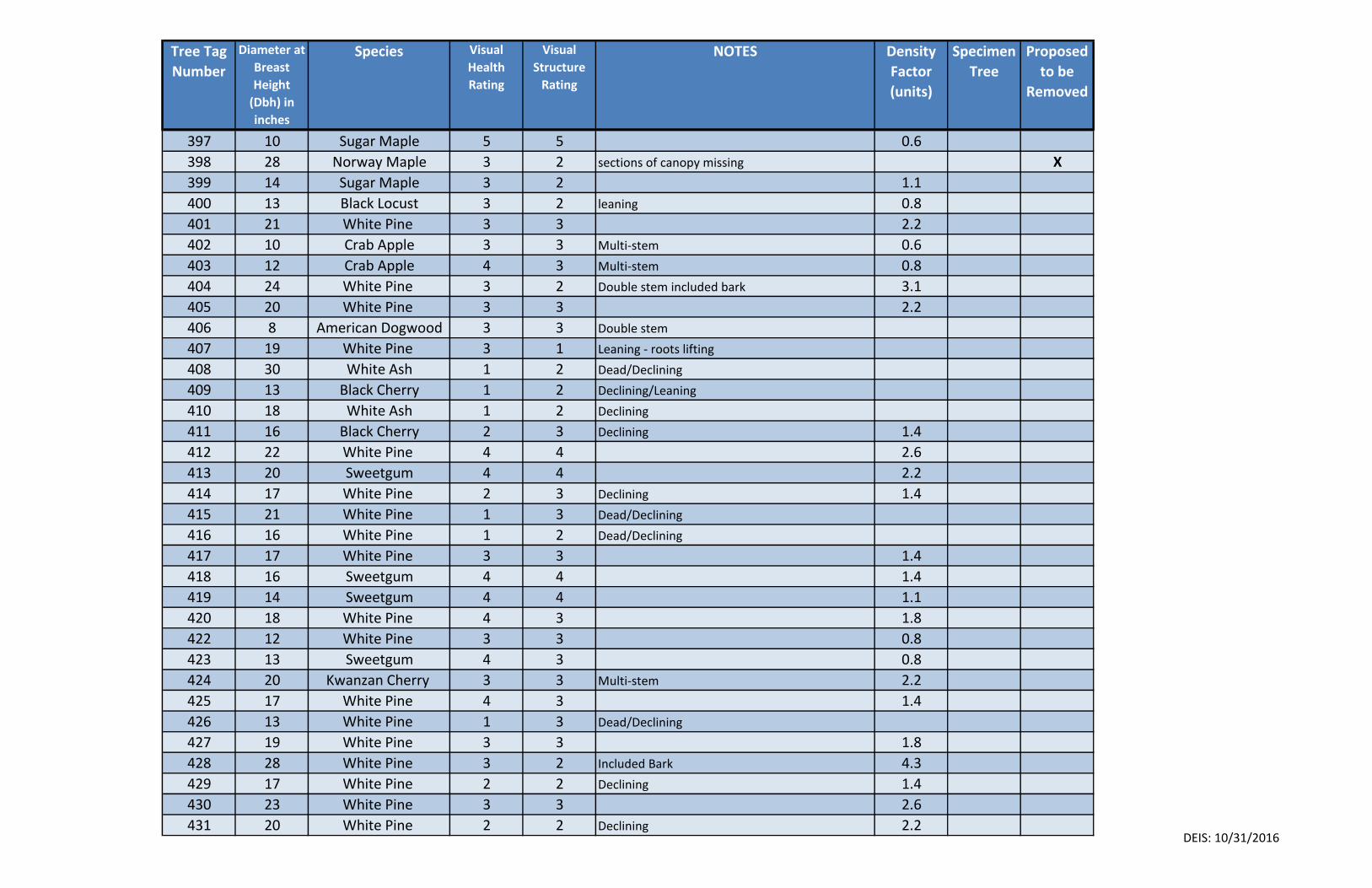
Tree Tag
Number
Diameter at
Breast
Height
(Dbh) in
inches
Species Visual
Health
Rating
Visual
Structure
Rating
NOTES Density
Factor
(units)
Specimen
Tree
Proposed
to be
Removed
397 10 Sugar Maple 5 5 0.6
398 28 Norway Maple 3 2 sections of canopy missing X
399 14 Sugar Maple 3 2 1.1
400 13 Black Locust 3 2 leaning 0.8
401 21 White Pine 3 3 2.2
402 10 Crab Apple 3 3 Multi-stem 0.6
403 12 Crab Apple 4 3 Multi-stem 0.8
404 24 White Pine 3 2 Double stem included bark 3.1
405 20 White Pine 3 3 2.2
406 8 American Dogwood 3 3 Double stem
407 19 White Pine 3 1 Leaning - roots lifting
408 30 White Ash 1 2 Dead/Declining
409 13 Black Cherry 1 2 Declining/Leaning
410 18 White Ash 1 2 Declining
411 16 Black Cherry 2 3 Declining 1.4
412 22 White Pine 4 4 2.6
413 20 Sweetgum 4 4 2.2
414 17 White Pine 2 3 Declining 1.4
415 21 White Pine 1 3 Dead/Declining
416 16 White Pine 1 2 Dead/Declining
417 17 White Pine 3 3 1.4
418 16 Sweetgum 4 4 1.4
419 14 Sweetgum 4 4 1.1
420 18 White Pine 4 3 1.8
422 12 White Pine 3 3 0.8
423 13 Sweetgum 4 3 0.8
424 20 Kwanzan Cherry 3 3 Multi-stem 2.2
425 17 White Pine 4 3 1.4
426 13 White Pine 1 3 Dead/Declining
427 19 White Pine 3 3 1.8
428 28 White Pine 3 2 Included Bark 4.3
429 17 White Pine 2 2 Declining 1.4
430 23 White Pine 3 3 2.6
431 20 White Pine 2 2 Declining 2.2DEIS: 10/31/2016
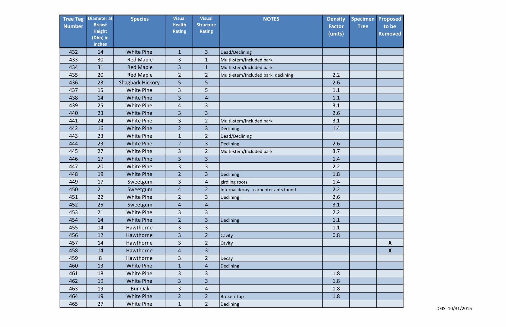
Tree Tag
Number
Diameter at
Breast
Height
(Dbh) in
inches
Species Visual
Health
Rating
Visual
Structure
Rating
NOTES Density
Factor
(units)
Specimen
Tree
Proposed
to be
Removed
432 14 White Pine 1 3 Dead/Declining
433 30 Red Maple 3 1 Multi-stem/Included bark
434 31 Red Maple 3 1 Multi-stem/Included bark
435 20 Red Maple 2 2 Multi-stem/Included bark, declining 2.2
436 23 Shagbark Hickory 5 5 2.6
437 15 White Pine 3 5 1.1
438 14 White Pine 3 4 1.1
439 25 White Pine 4 3 3.1
440 23 White Pine 3 3 2.6
441 24 White Pine 3 2 Multi-stem/Included bark 3.1
442 16 White Pine 2 3 Declining 1.4
443 23 White Pine 1 2 Dead/Declining
444 23 White Pine 2 3 Declining 2.6
445 27 White Pine 3 2 Multi-stem/Included bark 3.7
446 17 White Pine 3 3 1.4
447 20 White Pine 3 3 2.2
448 19 White Pine 2 3 Declining 1.8
449 17 Sweetgum 3 4 girdling roots 1.4
450 21 Sweetgum 4 2 Internal decay - carpenter ants found 2.2
451 22 White Pine 2 3 Declining 2.6
452 25 Sweetgum 4 4 3.1
453 21 White Pine 3 3 2.2
454 14 White Pine 2 3 Declining 1.1
455 14 Hawthorne 3 3 1.1
456 12 Hawthorne 3 2 Cavity 0.8
457 14 Hawthorne 3 2 Cavity X
458 14 Hawthorne 4 3 X
459 8 Hawthorne 3 2 Decay
460 13 White Pine 1 4 Declining
461 18 White Pine 3 3 1.8
462 19 White Pine 3 3 1.8
463 19 Bur Oak 3 4 1.8
464 19 White Pine 2 2 Broken Top 1.8
465 27 White Pine 1 2 Declining DEIS: 10/31/2016
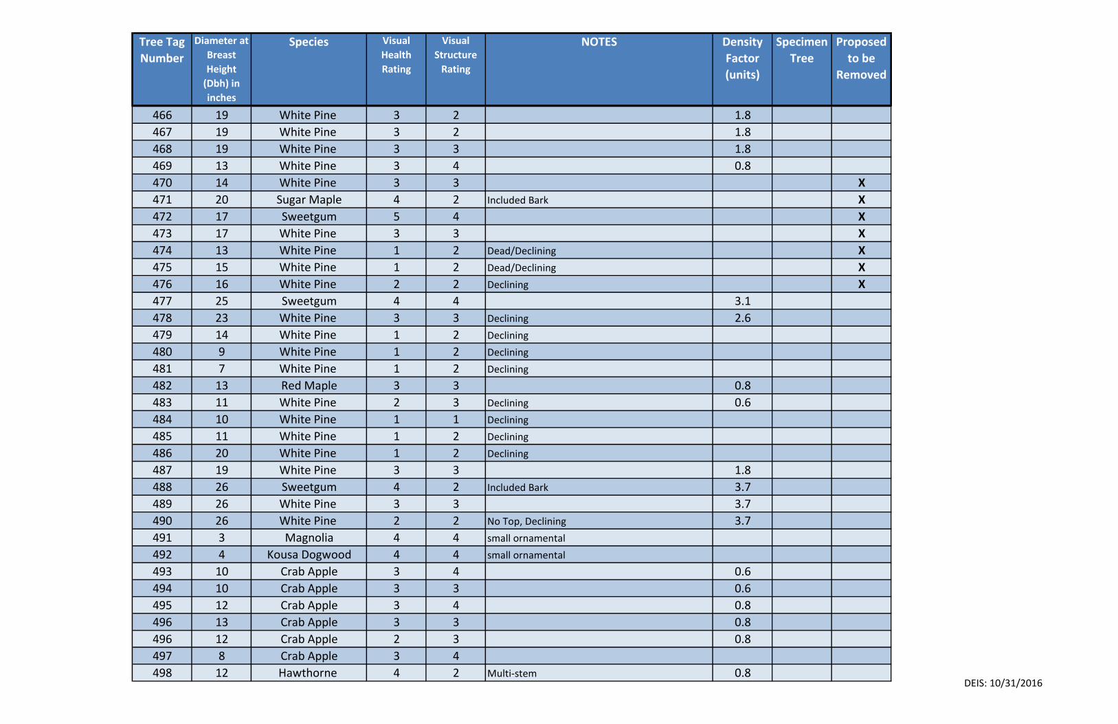
Tree Tag
Number
Diameter at
Breast
Height
(Dbh) in
inches
Species Visual
Health
Rating
Visual
Structure
Rating
NOTES Density
Factor
(units)
Specimen
Tree
Proposed
to be
Removed
466 19 White Pine 3 2 1.8
467 19 White Pine 3 2 1.8
468 19 White Pine 3 3 1.8
469 13 White Pine 3 4 0.8
470 14 White Pine 3 3 X
471 20 Sugar Maple 4 2 Included Bark X
472 17 Sweetgum 5 4 X
473 17 White Pine 3 3 X
474 13 White Pine 1 2 Dead/Declining X
475 15 White Pine 1 2 Dead/Declining X
476 16 White Pine 2 2 Declining X
477 25 Sweetgum 4 4 3.1
478 23 White Pine 3 3 Declining 2.6
479 14 White Pine 1 2 Declining
480 9 White Pine 1 2 Declining
481 7 White Pine 1 2 Declining
482 13 Red Maple 3 3 0.8
483 11 White Pine 2 3 Declining 0.6
484 10 White Pine 1 1 Declining
485 11 White Pine 1 2 Declining
486 20 White Pine 1 2 Declining
487 19 White Pine 3 3 1.8
488 26 Sweetgum 4 2 Included Bark 3.7
489 26 White Pine 3 3 3.7
490 26 White Pine 2 2 No Top, Declining 3.7
491 3 Magnolia 4 4 small ornamental
492 4 Kousa Dogwood 4 4 small ornamental
493 10 Crab Apple 3 4 0.6
494 10 Crab Apple 3 3 0.6
495 12 Crab Apple 3 4 0.8
496 13 Crab Apple 3 3 0.8
496 12 Crab Apple 2 3 0.8
497 8 Crab Apple 3 4
498 12 Hawthorne 4 2 Multi-stem 0.8DEIS: 10/31/2016
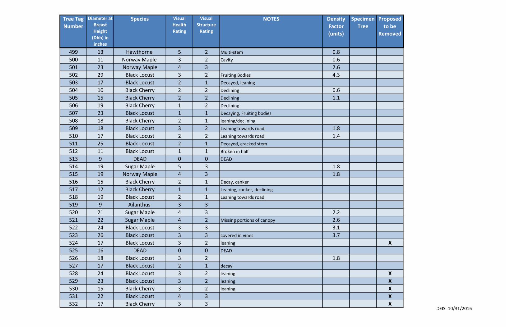
Tree Tag
Number
Diameter at
Breast
Height
(Dbh) in
inches
Species Visual
Health
Rating
Visual
Structure
Rating
NOTES Density
Factor
(units)
Specimen
Tree
Proposed
to be
Removed
499 13 Hawthorne 5 2 Multi-stem 0.8
500 11 Norway Maple 3 2 Cavity 0.6
501 23 Norway Maple 4 3 2.6
502 29 Black Locust 3 2 Fruiting Bodies 4.3
503 17 Black Locust 2 1 Decayed, leaning
504 10 Black Cherry 2 2 Declining 0.6
505 15 Black Cherry 2 2 Declining 1.1
506 19 Black Cherry 1 2 Declining
507 23 Black Locust 1 1 Decaying, Fruiting bodies
508 18 Black Cherry 2 1 leaning/declining
509 18 Black Locust 3 2 Leaning towards road 1.8
510 17 Black Locust 2 2 Leaning towards road 1.4
511 25 Black Locust 2 1 Decayed, cracked stem
512 11 Black Locust 1 1 Broken in half
513 9 DEAD 0 0 DEAD
514 19 Sugar Maple 5 3 1.8
515 19 Norway Maple 4 3 1.8
516 15 Black Cherry 2 1 Decay, canker
517 12 Black Cherry 1 1 Leaning, canker, declining
518 19 Black Locust 2 1 Leaning towards road
519 9 Ailanthus 3 3
520 21 Sugar Maple 4 3 2.2
521 22 Sugar Maple 4 2 Missing portions of canopy 2.6
522 24 Black Locust 3 3 3.1
523 26 Black Locust 3 3 covered in vines 3.7
524 17 Black Locust 3 2 leaning X
525 16 DEAD 0 0 DEAD
526 18 Black Locust 3 2 1.8
527 17 Black Locust 2 1 decay
528 24 Black Locust 3 2 leaning X
529 23 Black Locust 3 2 leaning X
530 15 Black Cherry 3 2 leaning X
531 22 Black Locust 4 3 X
532 17 Black Cherry 3 3 XDEIS: 10/31/2016
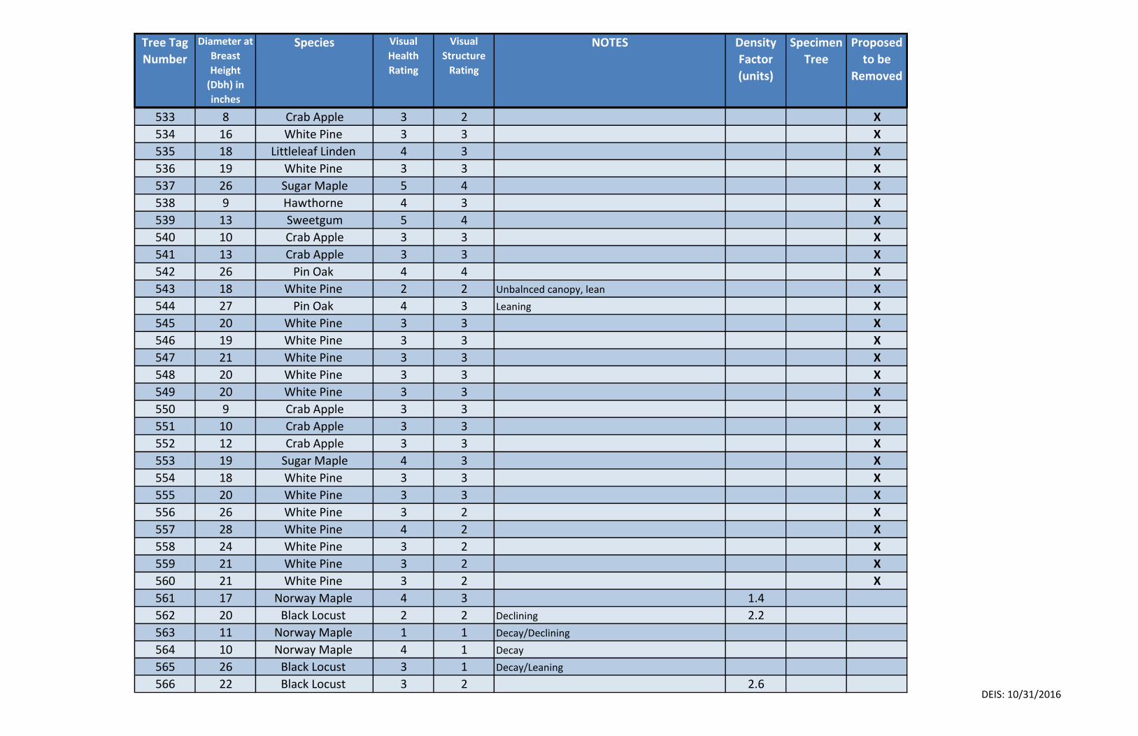
Tree Tag
Number
Diameter at
Breast
Height
(Dbh) in
inches
Species Visual
Health
Rating
Visual
Structure
Rating
NOTES Density
Factor
(units)
Specimen
Tree
Proposed
to be
Removed
533 8 Crab Apple 3 2 X
534 16 White Pine 3 3 X
535 18 Littleleaf Linden 4 3 X
536 19 White Pine 3 3 X
537 26 Sugar Maple 5 4 X
538 9 Hawthorne 4 3 X
539 13 Sweetgum 5 4 X
540 10 Crab Apple 3 3 X
541 13 Crab Apple 3 3 X
542 26 Pin Oak 4 4 X
543 18 White Pine 2 2 Unbalnced canopy, lean X
544 27 Pin Oak 4 3 Leaning X
545 20 White Pine 3 3 X
546 19 White Pine 3 3 X
547 21 White Pine 3 3 X
548 20 White Pine 3 3 X
549 20 White Pine 3 3 X
550 9 Crab Apple 3 3 X
551 10 Crab Apple 3 3 X
552 12 Crab Apple 3 3 X
553 19 Sugar Maple 4 3 X
554 18 White Pine 3 3 X
555 20 White Pine 3 3 X
556 26 White Pine 3 2 X
557 28 White Pine 4 2 X
558 24 White Pine 3 2 X
559 21 White Pine 3 2 X
560 21 White Pine 3 2 X
561 17 Norway Maple 4 3 1.4
562 20 Black Locust 2 2 Declining 2.2
563 11 Norway Maple 1 1 Decay/Declining
564 10 Norway Maple 4 1 Decay
565 26 Black Locust 3 1 Decay/Leaning
566 22 Black Locust 3 2 2.6DEIS: 10/31/2016
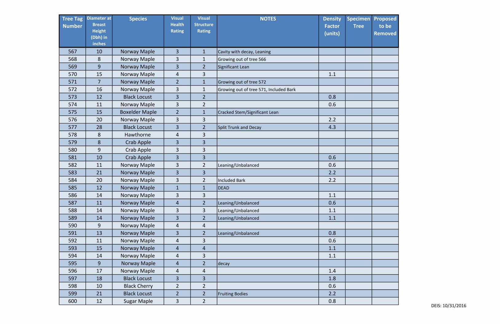
Tree Tag
Number
Diameter at
Breast
Height
(Dbh) in
inches
Species Visual
Health
Rating
Visual
Structure
Rating
NOTES Density
Factor
(units)
Specimen
Tree
Proposed
to be
Removed
567 10 Norway Maple 3 1 Cavity with decay, Leaning
568 8 Norway Maple 3 1 Growing out of tree 566
569 9 Norway Maple 3 2 Significant Lean
570 15 Norway Maple 4 3 1.1
571 7 Norway Maple 2 1 Growing out of tree 572
572 16 Norway Maple 3 1 Growing out of tree 571, Included Bark
573 12 Black Locust 3 2 0.8
574 11 Norway Maple 3 2 0.6
575 15 Boxelder Maple 2 1 Cracked Stem/Significant Lean
576 20 Norway Maple 3 3 2.2
577 28 Black Locust 3 2 Split Trunk and Decay 4.3
578 8 Hawthorne 4 3
579 8 Crab Apple 3 3
580 9 Crab Apple 3 3
581 10 Crab Apple 3 3 0.6
582 11 Norway Maple 3 2 Leaning/Unbalanced 0.6
583 21 Norway Maple 3 3 2.2
584 20 Norway Maple 3 2 Included Bark 2.2
585 12 Norway Maple 1 1 DEAD
586 14 Norway Maple 3 3 1.1
587 11 Norway Maple 4 2 Leaning/Unbalanced 0.6
588 14 Norway Maple 3 3 Leaning/Unbalanced 1.1
589 14 Norway Maple 3 2 Leaning/Unbalanced 1.1
590 9 Norway Maple 4 4
591 13 Norway Maple 3 2 Leaning/Unbalanced 0.8
592 11 Norway Maple 4 3 0.6
593 15 Norway Maple 4 4 1.1
594 14 Norway Maple 4 3 1.1
595 9 Norway Maple 4 2 decay
596 17 Norway Maple 4 4 1.4
597 18 Black Locust 3 3 1.8
598 10 Black Cherry 2 2 0.6
599 21 Black Locust 2 2 Fruiting Bodies 2.2
600 12 Sugar Maple 3 2 0.8DEIS: 10/31/2016
Explanation of Health Rating Visual Health Rating System - The health of each tree was based on a score between 1 & 5 with 5 being the highest score. Scores were based on the following:
1 – Very Poor – Tree exhibits severe dieback of branches, crown is thin, may show extensive pest infestation. Or tree is dead.
2 – Poor – Tree exhibits minor dieback of branches, annual shoot growth is short, slight signs of growth, probable pest infestations.
3 – Fair – Tree is typical for its species found in this area. Crown is full but may show signs of minor dieback
4 – Good – New growth is vigor and has good color (limited to time of year). Crown is full and exhibits vigorous shoot growth.
5 – Very Good – Tree exhibits excellent growth in canopy, foliage, stems and trunk. No signs of pests.
Explanation of Structure Rating Visual Structure Rating System - The Structure of each tree was based on a score between 1 & 5 with 5 being the highest score. Scores were based on the following:
1 – Very Poor – Trunk has cavities, may have multiple stems with included bark, and may have a significant lean.
2 – Poor – Branches have weak attachments to main stem. Crown is out of balance and may have a lean.
3 – Fair – Trunk and branches may have flaws but are typical to this species.
4 – Good – Trunk is straight with branches that exhibit a strong attachment. Branches may have flaws but are not obvious.
5 – Very Good – Tree exhibits good trunk taper and root flare. Has a balanced crown.
APPENDIX E
STORMWATER POLLUTION PREVENTION PLAN
(Refer to separate VOLUME II.E)
APPENDIX F
TRAFFIC IMPACT STUDY
1. Traffic Impact Study, dated December 9, 2016,
by Maser Consulting P.A.

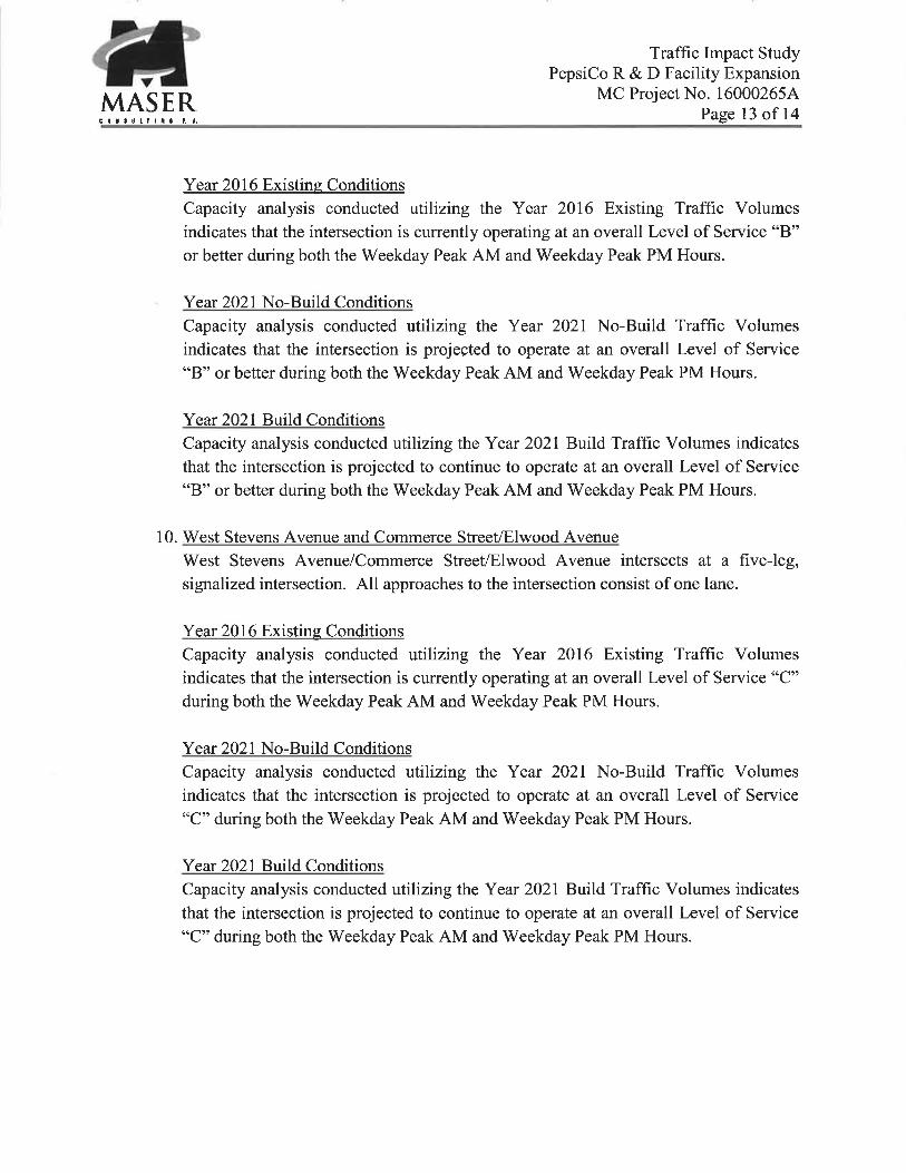

New Jersey New York Pennsylvania Virginia
Customer Loyalty through Client Satisfaction
SITE LOCATION MAP
PepsiCo R+D Facility ExpansionValhalla, New York
AutoCAD SHX Text
FIGURE NUMBER:
AutoCAD SHX Text
DATE:
AutoCAD SHX Text
JOB NUMBER:
AutoCAD SHX Text
Consulting, Municipal & Environmental Engineers Planners Surveyors Landscape Architects State of N.Y. Certificate of Authorization: 0008671
AutoCAD SHX Text
15000265A
AutoCAD SHX Text
09/19/2016
AutoCAD SHX Text
1
AutoCAD SHX Text
WESTCHESTER OFFICE 11 Bradhurst Avenue Hawthorne, NY 10532 Phone: 914.347.7500 Fax: 914.347.7266 email: solutions @ maserconsulting.com@ maserconsulting.com maserconsulting.commaserconsulting.com
AutoCAD SHX Text
LOZZA DRIVE
AutoCAD SHX Text
E. STEVENS
AutoCAD SHX Text
LORENZ
AutoCAD SHX Text
DRIVE
AutoCAD SHX Text
MOUNT PLEASANT TOWN HALL
AutoCAD SHX Text
TOWN HALL PLAZA
AutoCAD SHX Text
W. STEVENS AVENUE
AutoCAD SHX Text
THE SUMMIT
AutoCAD SHX Text
NANNY HAGEN ROAD
AutoCAD SHX Text
SITE
AutoCAD SHX Text
COLUMBUS
AutoCAD SHX Text
LAKEVIEW AVENUE
AutoCAD SHX Text
W. STEVENS AVENUE
AutoCAD SHX Text
ELWOOD AVENUE
AutoCAD SHX Text
COMMERCE STREET
AutoCAD SHX Text
COLUMBUS AVENUE
AutoCAD SHX Text
KENSICO ROAD
AutoCAD SHX Text
AVENUE
AutoCAD SHX Text
AVENUE
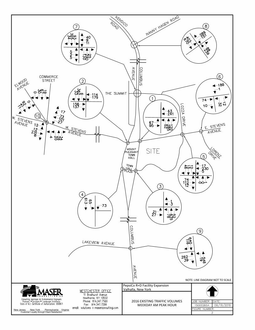
New Jersey New York Pennsylvania Virginia
Customer Loyalty through Client Satisfaction
NOTE: LINE DIAGRAM NOT TO SCALE
2016 EXISTING TRAFFIC VOLUMESWEEKDAY AM PEAK HOUR
PepsiCo R+D Facility ExpansionValhalla, New York
AutoCAD SHX Text
7
AutoCAD SHX Text
11
AutoCAD SHX Text
9
AutoCAD SHX Text
40
AutoCAD SHX Text
5
AutoCAD SHX Text
2
AutoCAD SHX Text
5
AutoCAD SHX Text
130
AutoCAD SHX Text
240
AutoCAD SHX Text
25
AutoCAD SHX Text
93
AutoCAD SHX Text
365
AutoCAD SHX Text
34
AutoCAD SHX Text
5
AutoCAD SHX Text
5
AutoCAD SHX Text
230
AutoCAD SHX Text
17
AutoCAD SHX Text
74
AutoCAD SHX Text
112
AutoCAD SHX Text
12
AutoCAD SHX Text
0
AutoCAD SHX Text
0
AutoCAD SHX Text
1
AutoCAD SHX Text
12
AutoCAD SHX Text
15
AutoCAD SHX Text
46
AutoCAD SHX Text
1
AutoCAD SHX Text
241
AutoCAD SHX Text
43
AutoCAD SHX Text
67
AutoCAD SHX Text
95
AutoCAD SHX Text
52
AutoCAD SHX Text
285
AutoCAD SHX Text
120
AutoCAD SHX Text
3
AutoCAD SHX Text
3
AutoCAD SHX Text
1
AutoCAD SHX Text
21
AutoCAD SHX Text
27
AutoCAD SHX Text
76
AutoCAD SHX Text
435
AutoCAD SHX Text
52
AutoCAD SHX Text
2
AutoCAD SHX Text
179
AutoCAD SHX Text
114
AutoCAD SHX Text
156
AutoCAD SHX Text
137
AutoCAD SHX Text
6
AutoCAD SHX Text
362
AutoCAD SHX Text
33
AutoCAD SHX Text
4
AutoCAD SHX Text
73
AutoCAD SHX Text
65
AutoCAD SHX Text
613
AutoCAD SHX Text
6
AutoCAD SHX Text
1
AutoCAD SHX Text
186
AutoCAD SHX Text
74
AutoCAD SHX Text
10
AutoCAD SHX Text
32
AutoCAD SHX Text
12
AutoCAD SHX Text
10
AutoCAD SHX Text
27
AutoCAD SHX Text
101
AutoCAD SHX Text
73
AutoCAD SHX Text
12
AutoCAD SHX Text
231
AutoCAD SHX Text
8
AutoCAD SHX Text
4
AutoCAD SHX Text
26
AutoCAD SHX Text
34
AutoCAD SHX Text
19
AutoCAD SHX Text
67
AutoCAD SHX Text
30
AutoCAD SHX Text
640
AutoCAD SHX Text
116
AutoCAD SHX Text
262
AutoCAD SHX Text
39
AutoCAD SHX Text
19
AutoCAD SHX Text
546
AutoCAD SHX Text
9
AutoCAD SHX Text
8
AutoCAD SHX Text
FIGURE NUMBER:
AutoCAD SHX Text
DATE:
AutoCAD SHX Text
JOB NUMBER:
AutoCAD SHX Text
Consulting, Municipal & Environmental Engineers Planners Surveyors Landscape Architects State of N.Y. Certificate of Authorization: 0008671
AutoCAD SHX Text
15000265A
AutoCAD SHX Text
09/19/2016
AutoCAD SHX Text
WESTCHESTER OFFICE 11 Bradhurst Avenue Hawthorne, NY 10532 Phone: 914.347.7500 Fax: 914.347.7266 email: solutions @ maserconsulting.com@ maserconsulting.com maserconsulting.commaserconsulting.com
AutoCAD SHX Text
2
AutoCAD SHX Text
LOZZA DRIVE
AutoCAD SHX Text
E. STEVENS
AutoCAD SHX Text
LORENZ
AutoCAD SHX Text
DRIVE
AutoCAD SHX Text
MOUNT PLEASANT TOWN HALL
AutoCAD SHX Text
TOWN HALL PLAZA
AutoCAD SHX Text
W. STEVENS AVENUE
AutoCAD SHX Text
THE SUMMIT
AutoCAD SHX Text
NANNY HAGEN ROAD
AutoCAD SHX Text
SITE
AutoCAD SHX Text
COLUMBUS
AutoCAD SHX Text
LAKEVIEW AVENUE
AutoCAD SHX Text
W. STEVENS AVENUE
AutoCAD SHX Text
ELWOOD AVENUE
AutoCAD SHX Text
COMMERCE STREET
AutoCAD SHX Text
COLUMBUS AVENUE
AutoCAD SHX Text
KENSICO ROAD
AutoCAD SHX Text
AVENUE
AutoCAD SHX Text
AVENUE
AutoCAD SHX Text
151
AutoCAD SHX Text
289
AutoCAD SHX Text
239
AutoCAD SHX Text
88
AutoCAD SHX Text
403
AutoCAD SHX Text
670
AutoCAD SHX Text
12
AutoCAD SHX Text
17
AutoCAD SHX Text
20
AutoCAD SHX Text
0
AutoCAD SHX Text
41
AutoCAD SHX Text
11
AutoCAD SHX Text
92
AutoCAD SHX Text
0

New Jersey New York Pennsylvania Virginia
Customer Loyalty through Client Satisfaction
NOTE: LINE DIAGRAM NOT TO SCALE
2016 EXISTING TRAFFIC VOLUMESWEEKDAY PM PEAK HOUR
PepsiCo R+D Facility ExpansionValhalla, New York
AutoCAD SHX Text
7
AutoCAD SHX Text
10
AutoCAD SHX Text
3
AutoCAD SHX Text
61
AutoCAD SHX Text
27
AutoCAD SHX Text
4
AutoCAD SHX Text
24
AutoCAD SHX Text
9
AutoCAD SHX Text
333
AutoCAD SHX Text
14
AutoCAD SHX Text
45
AutoCAD SHX Text
281
AutoCAD SHX Text
2
AutoCAD SHX Text
5
AutoCAD SHX Text
0
AutoCAD SHX Text
181
AutoCAD SHX Text
8
AutoCAD SHX Text
50
AutoCAD SHX Text
120
AutoCAD SHX Text
1
AutoCAD SHX Text
11
AutoCAD SHX Text
8
AutoCAD SHX Text
2
AutoCAD SHX Text
37
AutoCAD SHX Text
2
AutoCAD SHX Text
64
AutoCAD SHX Text
1
AutoCAD SHX Text
248
AutoCAD SHX Text
39
AutoCAD SHX Text
33
AutoCAD SHX Text
56
AutoCAD SHX Text
87
AutoCAD SHX Text
284
AutoCAD SHX Text
126
AutoCAD SHX Text
3
AutoCAD SHX Text
91
AutoCAD SHX Text
32
AutoCAD SHX Text
25
AutoCAD SHX Text
0
AutoCAD SHX Text
20
AutoCAD SHX Text
440
AutoCAD SHX Text
9
AutoCAD SHX Text
2
AutoCAD SHX Text
133
AutoCAD SHX Text
202
AutoCAD SHX Text
86
AutoCAD SHX Text
40
AutoCAD SHX Text
3
AutoCAD SHX Text
341
AutoCAD SHX Text
92
AutoCAD SHX Text
4
AutoCAD SHX Text
119
AutoCAD SHX Text
10
AutoCAD SHX Text
504
AutoCAD SHX Text
6
AutoCAD SHX Text
3
AutoCAD SHX Text
130
AutoCAD SHX Text
151
AutoCAD SHX Text
20
AutoCAD SHX Text
14
AutoCAD SHX Text
0
AutoCAD SHX Text
10
AutoCAD SHX Text
31
AutoCAD SHX Text
265
AutoCAD SHX Text
70
AutoCAD SHX Text
16
AutoCAD SHX Text
60
AutoCAD SHX Text
13
AutoCAD SHX Text
8
AutoCAD SHX Text
92
AutoCAD SHX Text
41
AutoCAD SHX Text
11
AutoCAD SHX Text
16
AutoCAD SHX Text
21
AutoCAD SHX Text
525
AutoCAD SHX Text
196
AutoCAD SHX Text
130
AutoCAD SHX Text
48
AutoCAD SHX Text
34
AutoCAD SHX Text
454
AutoCAD SHX Text
9
AutoCAD SHX Text
8
AutoCAD SHX Text
FIGURE NUMBER:
AutoCAD SHX Text
DATE:
AutoCAD SHX Text
JOB NUMBER:
AutoCAD SHX Text
Consulting, Municipal & Environmental Engineers Planners Surveyors Landscape Architects State of N.Y. Certificate of Authorization: 0008671
AutoCAD SHX Text
15000265A
AutoCAD SHX Text
09/19/2016
AutoCAD SHX Text
WESTCHESTER OFFICE 11 Bradhurst Avenue Hawthorne, NY 10532 Phone: 914.347.7500 Fax: 914.347.7266 email: solutions @ maserconsulting.com@ maserconsulting.com maserconsulting.commaserconsulting.com
AutoCAD SHX Text
3
AutoCAD SHX Text
LOZZA DRIVE
AutoCAD SHX Text
E. STEVENS
AutoCAD SHX Text
LORENZ
AutoCAD SHX Text
DRIVE
AutoCAD SHX Text
MOUNT PLEASANT TOWN HALL
AutoCAD SHX Text
TOWN HALL PLAZA
AutoCAD SHX Text
W. STEVENS AVENUE
AutoCAD SHX Text
THE SUMMIT
AutoCAD SHX Text
NANNY HAGEN ROAD
AutoCAD SHX Text
SITE
AutoCAD SHX Text
COLUMBUS
AutoCAD SHX Text
LAKEVIEW AVENUE
AutoCAD SHX Text
W. STEVENS AVENUE
AutoCAD SHX Text
ELWOOD AVENUE
AutoCAD SHX Text
COMMERCE STREET
AutoCAD SHX Text
COLUMBUS AVENUE
AutoCAD SHX Text
KENSICO ROAD
AutoCAD SHX Text
AVENUE
AutoCAD SHX Text
AVENUE
AutoCAD SHX Text
92
AutoCAD SHX Text
345
AutoCAD SHX Text
611
AutoCAD SHX Text
127
AutoCAD SHX Text
313
AutoCAD SHX Text
330
AutoCAD SHX Text
20
AutoCAD SHX Text
22
AutoCAD SHX Text
50
AutoCAD SHX Text
0
AutoCAD SHX Text
34
AutoCAD SHX Text
25
AutoCAD SHX Text
51
AutoCAD SHX Text
0

New Jersey New York Pennsylvania Virginia
Customer Loyalty through Client Satisfaction
NOTE: LINE DIAGRAM NOT TO SCALE
2021 PROJECTED TRAFFIC VOLUMESWEEKDAY AM PEAK HOUR
PepsiCo R+D Facility ExpansionValhalla, New York
AutoCAD SHX Text
7
AutoCAD SHX Text
12
AutoCAD SHX Text
9
AutoCAD SHX Text
42
AutoCAD SHX Text
5
AutoCAD SHX Text
2
AutoCAD SHX Text
5
AutoCAD SHX Text
137
AutoCAD SHX Text
252
AutoCAD SHX Text
26
AutoCAD SHX Text
98
AutoCAD SHX Text
383
AutoCAD SHX Text
36
AutoCAD SHX Text
5
AutoCAD SHX Text
5
AutoCAD SHX Text
242
AutoCAD SHX Text
18
AutoCAD SHX Text
78
AutoCAD SHX Text
118
AutoCAD SHX Text
13
AutoCAD SHX Text
0
AutoCAD SHX Text
0
AutoCAD SHX Text
1
AutoCAD SHX Text
13
AutoCAD SHX Text
16
AutoCAD SHX Text
48
AutoCAD SHX Text
1
AutoCAD SHX Text
253
AutoCAD SHX Text
45
AutoCAD SHX Text
70
AutoCAD SHX Text
100
AutoCAD SHX Text
55
AutoCAD SHX Text
299
AutoCAD SHX Text
126
AutoCAD SHX Text
3
AutoCAD SHX Text
3
AutoCAD SHX Text
1
AutoCAD SHX Text
22
AutoCAD SHX Text
28
AutoCAD SHX Text
80
AutoCAD SHX Text
457
AutoCAD SHX Text
55
AutoCAD SHX Text
2
AutoCAD SHX Text
188
AutoCAD SHX Text
120
AutoCAD SHX Text
164
AutoCAD SHX Text
144
AutoCAD SHX Text
6
AutoCAD SHX Text
380
AutoCAD SHX Text
35
AutoCAD SHX Text
4
AutoCAD SHX Text
77
AutoCAD SHX Text
68
AutoCAD SHX Text
644
AutoCAD SHX Text
6
AutoCAD SHX Text
1
AutoCAD SHX Text
195
AutoCAD SHX Text
78
AutoCAD SHX Text
11
AutoCAD SHX Text
34
AutoCAD SHX Text
13
AutoCAD SHX Text
10
AutoCAD SHX Text
28
AutoCAD SHX Text
106
AutoCAD SHX Text
77
AutoCAD SHX Text
13
AutoCAD SHX Text
243
AutoCAD SHX Text
8
AutoCAD SHX Text
4
AutoCAD SHX Text
27
AutoCAD SHX Text
36
AutoCAD SHX Text
20
AutoCAD SHX Text
70
AutoCAD SHX Text
32
AutoCAD SHX Text
672
AutoCAD SHX Text
122
AutoCAD SHX Text
275
AutoCAD SHX Text
41
AutoCAD SHX Text
20
AutoCAD SHX Text
573
AutoCAD SHX Text
9
AutoCAD SHX Text
8
AutoCAD SHX Text
FIGURE NUMBER:
AutoCAD SHX Text
DATE:
AutoCAD SHX Text
JOB NUMBER:
AutoCAD SHX Text
Consulting, Municipal & Environmental Engineers Planners Surveyors Landscape Architects State of N.Y. Certificate of Authorization: 0008671
AutoCAD SHX Text
15000265A
AutoCAD SHX Text
09/19/2016
AutoCAD SHX Text
WESTCHESTER OFFICE 11 Bradhurst Avenue Hawthorne, NY 10532 Phone: 914.347.7500 Fax: 914.347.7266 email: solutions @ maserconsulting.com@ maserconsulting.com maserconsulting.commaserconsulting.com
AutoCAD SHX Text
4
AutoCAD SHX Text
LOZZA DRIVE
AutoCAD SHX Text
E. STEVENS
AutoCAD SHX Text
LORENZ
AutoCAD SHX Text
DRIVE
AutoCAD SHX Text
MOUNT PLEASANT TOWN HALL
AutoCAD SHX Text
TOWN HALL PLAZA
AutoCAD SHX Text
W. STEVENS AVENUE
AutoCAD SHX Text
THE SUMMIT
AutoCAD SHX Text
NANNY HAGEN ROAD
AutoCAD SHX Text
SITE
AutoCAD SHX Text
COLUMBUS
AutoCAD SHX Text
LAKEVIEW AVENUE
AutoCAD SHX Text
W. STEVENS AVENUE
AutoCAD SHX Text
ELWOOD AVENUE
AutoCAD SHX Text
COMMERCE STREET
AutoCAD SHX Text
COLUMBUS AVENUE
AutoCAD SHX Text
KENSICO ROAD
AutoCAD SHX Text
AVENUE
AutoCAD SHX Text
AVENUE
AutoCAD SHX Text
159
AutoCAD SHX Text
303
AutoCAD SHX Text
251
AutoCAD SHX Text
92
AutoCAD SHX Text
423
AutoCAD SHX Text
704
AutoCAD SHX Text
13
AutoCAD SHX Text
18
AutoCAD SHX Text
21
AutoCAD SHX Text
0
AutoCAD SHX Text
43
AutoCAD SHX Text
12
AutoCAD SHX Text
97
AutoCAD SHX Text
0

New Jersey New York Pennsylvania Virginia
Customer Loyalty through Client Satisfaction
NOTE: LINE DIAGRAM NOT TO SCALE
2021 PROJECTED TRAFFIC VOLUMESWEEKDAY PM PEAK HOUR
PepsiCo R+D Facility ExpansionValhalla, New York
AutoCAD SHX Text
7
AutoCAD SHX Text
11
AutoCAD SHX Text
3
AutoCAD SHX Text
64
AutoCAD SHX Text
28
AutoCAD SHX Text
4
AutoCAD SHX Text
25
AutoCAD SHX Text
9
AutoCAD SHX Text
350
AutoCAD SHX Text
15
AutoCAD SHX Text
47
AutoCAD SHX Text
295
AutoCAD SHX Text
2
AutoCAD SHX Text
5
AutoCAD SHX Text
0
AutoCAD SHX Text
190
AutoCAD SHX Text
8
AutoCAD SHX Text
53
AutoCAD SHX Text
126
AutoCAD SHX Text
1
AutoCAD SHX Text
12
AutoCAD SHX Text
8
AutoCAD SHX Text
2
AutoCAD SHX Text
39
AutoCAD SHX Text
2
AutoCAD SHX Text
67
AutoCAD SHX Text
1
AutoCAD SHX Text
260
AutoCAD SHX Text
41
AutoCAD SHX Text
35
AutoCAD SHX Text
59
AutoCAD SHX Text
91
AutoCAD SHX Text
298
AutoCAD SHX Text
132
AutoCAD SHX Text
3
AutoCAD SHX Text
96
AutoCAD SHX Text
34
AutoCAD SHX Text
26
AutoCAD SHX Text
0
AutoCAD SHX Text
21
AutoCAD SHX Text
462
AutoCAD SHX Text
9
AutoCAD SHX Text
2
AutoCAD SHX Text
140
AutoCAD SHX Text
212
AutoCAD SHX Text
90
AutoCAD SHX Text
42
AutoCAD SHX Text
3
AutoCAD SHX Text
358
AutoCAD SHX Text
97
AutoCAD SHX Text
4
AutoCAD SHX Text
125
AutoCAD SHX Text
11
AutoCAD SHX Text
529
AutoCAD SHX Text
6
AutoCAD SHX Text
3
AutoCAD SHX Text
137
AutoCAD SHX Text
159
AutoCAD SHX Text
21
AutoCAD SHX Text
15
AutoCAD SHX Text
0
AutoCAD SHX Text
10
AutoCAD SHX Text
33
AutoCAD SHX Text
278
AutoCAD SHX Text
74
AutoCAD SHX Text
17
AutoCAD SHX Text
63
AutoCAD SHX Text
14
AutoCAD SHX Text
8
AutoCAD SHX Text
97
AutoCAD SHX Text
43
AutoCAD SHX Text
12
AutoCAD SHX Text
17
AutoCAD SHX Text
22
AutoCAD SHX Text
551
AutoCAD SHX Text
206
AutoCAD SHX Text
137
AutoCAD SHX Text
50
AutoCAD SHX Text
36
AutoCAD SHX Text
477
AutoCAD SHX Text
9
AutoCAD SHX Text
8
AutoCAD SHX Text
FIGURE NUMBER:
AutoCAD SHX Text
DATE:
AutoCAD SHX Text
JOB NUMBER:
AutoCAD SHX Text
Consulting, Municipal & Environmental Engineers Planners Surveyors Landscape Architects State of N.Y. Certificate of Authorization: 0008671
AutoCAD SHX Text
15000265A
AutoCAD SHX Text
09/19/2016
AutoCAD SHX Text
WESTCHESTER OFFICE 11 Bradhurst Avenue Hawthorne, NY 10532 Phone: 914.347.7500 Fax: 914.347.7266 email: solutions @ maserconsulting.com@ maserconsulting.com maserconsulting.commaserconsulting.com
AutoCAD SHX Text
5
AutoCAD SHX Text
LOZZA DRIVE
AutoCAD SHX Text
E. STEVENS
AutoCAD SHX Text
LORENZ
AutoCAD SHX Text
DRIVE
AutoCAD SHX Text
MOUNT PLEASANT TOWN HALL
AutoCAD SHX Text
TOWN HALL PLAZA
AutoCAD SHX Text
W. STEVENS AVENUE
AutoCAD SHX Text
THE SUMMIT
AutoCAD SHX Text
NANNY HAGEN ROAD
AutoCAD SHX Text
SITE
AutoCAD SHX Text
COLUMBUS
AutoCAD SHX Text
LAKEVIEW AVENUE
AutoCAD SHX Text
W. STEVENS AVENUE
AutoCAD SHX Text
ELWOOD AVENUE
AutoCAD SHX Text
COMMERCE STREET
AutoCAD SHX Text
COLUMBUS AVENUE
AutoCAD SHX Text
KENSICO ROAD
AutoCAD SHX Text
AVENUE
AutoCAD SHX Text
AVENUE
AutoCAD SHX Text
97
AutoCAD SHX Text
362
AutoCAD SHX Text
642
AutoCAD SHX Text
133
AutoCAD SHX Text
329
AutoCAD SHX Text
347
AutoCAD SHX Text
21
AutoCAD SHX Text
23
AutoCAD SHX Text
53
AutoCAD SHX Text
0
AutoCAD SHX Text
36
AutoCAD SHX Text
26
AutoCAD SHX Text
54
AutoCAD SHX Text
0

New Jersey New York Pennsylvania Virginia
Customer Loyalty through Client Satisfaction
NOTE: LINE DIAGRAM NOT TO SCALE
OTHER DEVELOPMENT TRAFFIC VOLUMESWEEKDAY AM PEAK HOUR
PepsiCo R+D Facility ExpansionValhalla, New York
AutoCAD SHX Text
7
AutoCAD SHX Text
0
AutoCAD SHX Text
0
AutoCAD SHX Text
0
AutoCAD SHX Text
0
AutoCAD SHX Text
0
AutoCAD SHX Text
0
AutoCAD SHX Text
0
AutoCAD SHX Text
46
AutoCAD SHX Text
0
AutoCAD SHX Text
0
AutoCAD SHX Text
24
AutoCAD SHX Text
0
AutoCAD SHX Text
5
AutoCAD SHX Text
0
AutoCAD SHX Text
58
AutoCAD SHX Text
0
AutoCAD SHX Text
0
AutoCAD SHX Text
24
AutoCAD SHX Text
0
AutoCAD SHX Text
0
AutoCAD SHX Text
0
AutoCAD SHX Text
0
AutoCAD SHX Text
0
AutoCAD SHX Text
0
AutoCAD SHX Text
0
AutoCAD SHX Text
1
AutoCAD SHX Text
43
AutoCAD SHX Text
15
AutoCAD SHX Text
15
AutoCAD SHX Text
13
AutoCAD SHX Text
3
AutoCAD SHX Text
16
AutoCAD SHX Text
11
AutoCAD SHX Text
3
AutoCAD SHX Text
0
AutoCAD SHX Text
0
AutoCAD SHX Text
0
AutoCAD SHX Text
0
AutoCAD SHX Text
0
AutoCAD SHX Text
30
AutoCAD SHX Text
0
AutoCAD SHX Text
2
AutoCAD SHX Text
33
AutoCAD SHX Text
14
AutoCAD SHX Text
21
AutoCAD SHX Text
7
AutoCAD SHX Text
6
AutoCAD SHX Text
9
AutoCAD SHX Text
9
AutoCAD SHX Text
4
AutoCAD SHX Text
0
AutoCAD SHX Text
0
AutoCAD SHX Text
49
AutoCAD SHX Text
6
AutoCAD SHX Text
0
AutoCAD SHX Text
58
AutoCAD SHX Text
24
AutoCAD SHX Text
0
AutoCAD SHX Text
0
AutoCAD SHX Text
0
AutoCAD SHX Text
10
AutoCAD SHX Text
3
AutoCAD SHX Text
14
AutoCAD SHX Text
5
AutoCAD SHX Text
0
AutoCAD SHX Text
14
AutoCAD SHX Text
0
AutoCAD SHX Text
0
AutoCAD SHX Text
0
AutoCAD SHX Text
2
AutoCAD SHX Text
1
AutoCAD SHX Text
0
AutoCAD SHX Text
0
AutoCAD SHX Text
33
AutoCAD SHX Text
16
AutoCAD SHX Text
12
AutoCAD SHX Text
0
AutoCAD SHX Text
0
AutoCAD SHX Text
18
AutoCAD SHX Text
9
AutoCAD SHX Text
8
AutoCAD SHX Text
FIGURE NUMBER:
AutoCAD SHX Text
DATE:
AutoCAD SHX Text
JOB NUMBER:
AutoCAD SHX Text
Consulting, Municipal & Environmental Engineers Planners Surveyors Landscape Architects State of N.Y. Certificate of Authorization: 0008671
AutoCAD SHX Text
15000265A
AutoCAD SHX Text
09/19/2016
AutoCAD SHX Text
WESTCHESTER OFFICE 11 Bradhurst Avenue Hawthorne, NY 10532 Phone: 914.347.7500 Fax: 914.347.7266 email: solutions @ maserconsulting.com@ maserconsulting.com maserconsulting.commaserconsulting.com
AutoCAD SHX Text
6
AutoCAD SHX Text
LOZZA DRIVE
AutoCAD SHX Text
E. STEVENS
AutoCAD SHX Text
LORENZ
AutoCAD SHX Text
DRIVE
AutoCAD SHX Text
MOUNT PLEASANT TOWN HALL
AutoCAD SHX Text
TOWN HALL PLAZA
AutoCAD SHX Text
W. STEVENS AVENUE
AutoCAD SHX Text
THE SUMMIT
AutoCAD SHX Text
NANNY HAGEN ROAD
AutoCAD SHX Text
SITE
AutoCAD SHX Text
COLUMBUS
AutoCAD SHX Text
LAKEVIEW AVENUE
AutoCAD SHX Text
W. STEVENS AVENUE
AutoCAD SHX Text
ELWOOD AVENUE
AutoCAD SHX Text
COMMERCE STREET
AutoCAD SHX Text
COLUMBUS AVENUE
AutoCAD SHX Text
KENSICO ROAD
AutoCAD SHX Text
AVENUE
AutoCAD SHX Text
AVENUE
AutoCAD SHX Text
17
AutoCAD SHX Text
10
AutoCAD SHX Text
34
AutoCAD SHX Text
13
AutoCAD SHX Text
3
AutoCAD SHX Text
30
AutoCAD SHX Text
0
AutoCAD SHX Text
3
AutoCAD SHX Text
0
AutoCAD SHX Text
0
AutoCAD SHX Text
0
AutoCAD SHX Text
0
AutoCAD SHX Text
3
AutoCAD SHX Text
0

New Jersey New York Pennsylvania Virginia
Customer Loyalty through Client Satisfaction
NOTE: LINE DIAGRAM NOT TO SCALE
OTHER DEVELOPMENT TRAFFIC VOLUMESWEEKDAY PM PEAK HOUR
PepsiCo R+D Facility ExpansionValhalla, New York
AutoCAD SHX Text
7
AutoCAD SHX Text
0
AutoCAD SHX Text
0
AutoCAD SHX Text
0
AutoCAD SHX Text
0
AutoCAD SHX Text
0
AutoCAD SHX Text
0
AutoCAD SHX Text
0
AutoCAD SHX Text
39
AutoCAD SHX Text
0
AutoCAD SHX Text
0
AutoCAD SHX Text
38
AutoCAD SHX Text
0
AutoCAD SHX Text
5
AutoCAD SHX Text
0
AutoCAD SHX Text
42
AutoCAD SHX Text
0
AutoCAD SHX Text
0
AutoCAD SHX Text
67
AutoCAD SHX Text
0
AutoCAD SHX Text
0
AutoCAD SHX Text
0
AutoCAD SHX Text
0
AutoCAD SHX Text
0
AutoCAD SHX Text
0
AutoCAD SHX Text
0
AutoCAD SHX Text
1
AutoCAD SHX Text
31
AutoCAD SHX Text
11
AutoCAD SHX Text
14
AutoCAD SHX Text
30
AutoCAD SHX Text
7
AutoCAD SHX Text
14
AutoCAD SHX Text
37
AutoCAD SHX Text
3
AutoCAD SHX Text
0
AutoCAD SHX Text
0
AutoCAD SHX Text
0
AutoCAD SHX Text
0
AutoCAD SHX Text
0
AutoCAD SHX Text
58
AutoCAD SHX Text
0
AutoCAD SHX Text
2
AutoCAD SHX Text
22
AutoCAD SHX Text
16
AutoCAD SHX Text
27
AutoCAD SHX Text
4
AutoCAD SHX Text
17
AutoCAD SHX Text
10
AutoCAD SHX Text
11
AutoCAD SHX Text
4
AutoCAD SHX Text
0
AutoCAD SHX Text
0
AutoCAD SHX Text
36
AutoCAD SHX Text
6
AutoCAD SHX Text
0
AutoCAD SHX Text
42
AutoCAD SHX Text
67
AutoCAD SHX Text
0
AutoCAD SHX Text
0
AutoCAD SHX Text
0
AutoCAD SHX Text
10
AutoCAD SHX Text
3
AutoCAD SHX Text
12
AutoCAD SHX Text
3
AutoCAD SHX Text
0
AutoCAD SHX Text
19
AutoCAD SHX Text
0
AutoCAD SHX Text
0
AutoCAD SHX Text
0
AutoCAD SHX Text
3
AutoCAD SHX Text
3
AutoCAD SHX Text
0
AutoCAD SHX Text
0
AutoCAD SHX Text
23
AutoCAD SHX Text
12
AutoCAD SHX Text
20
AutoCAD SHX Text
0
AutoCAD SHX Text
0
AutoCAD SHX Text
38
AutoCAD SHX Text
9
AutoCAD SHX Text
8
AutoCAD SHX Text
FIGURE NUMBER:
AutoCAD SHX Text
DATE:
AutoCAD SHX Text
JOB NUMBER:
AutoCAD SHX Text
Consulting, Municipal & Environmental Engineers Planners Surveyors Landscape Architects State of N.Y. Certificate of Authorization: 0008671
AutoCAD SHX Text
15000265A
AutoCAD SHX Text
09/19/2016
AutoCAD SHX Text
WESTCHESTER OFFICE 11 Bradhurst Avenue Hawthorne, NY 10532 Phone: 914.347.7500 Fax: 914.347.7266 email: solutions @ maserconsulting.com@ maserconsulting.com maserconsulting.commaserconsulting.com
AutoCAD SHX Text
7
AutoCAD SHX Text
LOZZA DRIVE
AutoCAD SHX Text
E. STEVENS
AutoCAD SHX Text
LORENZ
AutoCAD SHX Text
DRIVE
AutoCAD SHX Text
MOUNT PLEASANT TOWN HALL
AutoCAD SHX Text
TOWN HALL PLAZA
AutoCAD SHX Text
W. STEVENS AVENUE
AutoCAD SHX Text
THE SUMMIT
AutoCAD SHX Text
NANNY HAGEN ROAD
AutoCAD SHX Text
SITE
AutoCAD SHX Text
COLUMBUS
AutoCAD SHX Text
LAKEVIEW AVENUE
AutoCAD SHX Text
W. STEVENS AVENUE
AutoCAD SHX Text
ELWOOD AVENUE
AutoCAD SHX Text
COMMERCE STREET
AutoCAD SHX Text
COLUMBUS AVENUE
AutoCAD SHX Text
KENSICO ROAD
AutoCAD SHX Text
AVENUE
AutoCAD SHX Text
AVENUE
AutoCAD SHX Text
16
AutoCAD SHX Text
6
AutoCAD SHX Text
31
AutoCAD SHX Text
13
AutoCAD SHX Text
11
AutoCAD SHX Text
41
AutoCAD SHX Text
0
AutoCAD SHX Text
3
AutoCAD SHX Text
0
AutoCAD SHX Text
0
AutoCAD SHX Text
0
AutoCAD SHX Text
0
AutoCAD SHX Text
5
AutoCAD SHX Text
0
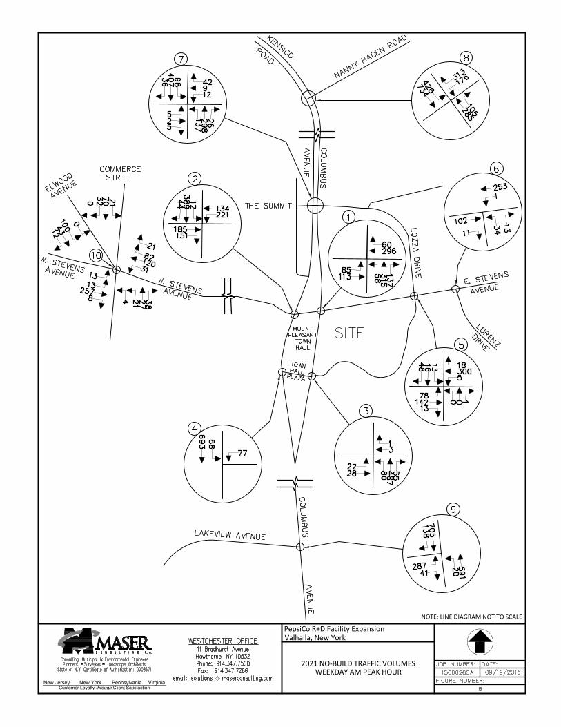
New Jersey New York Pennsylvania Virginia
Customer Loyalty through Client Satisfaction
NOTE: LINE DIAGRAM NOT TO SCALE
2021 NO-BUILD TRAFFIC VOLUMESWEEKDAY AM PEAK HOUR
PepsiCo R+D Facility ExpansionValhalla, New York
AutoCAD SHX Text
7
AutoCAD SHX Text
12
AutoCAD SHX Text
9
AutoCAD SHX Text
42
AutoCAD SHX Text
5
AutoCAD SHX Text
2
AutoCAD SHX Text
5
AutoCAD SHX Text
137
AutoCAD SHX Text
298
AutoCAD SHX Text
26
AutoCAD SHX Text
98
AutoCAD SHX Text
407
AutoCAD SHX Text
36
AutoCAD SHX Text
5
AutoCAD SHX Text
5
AutoCAD SHX Text
300
AutoCAD SHX Text
18
AutoCAD SHX Text
78
AutoCAD SHX Text
142
AutoCAD SHX Text
13
AutoCAD SHX Text
0
AutoCAD SHX Text
0
AutoCAD SHX Text
1
AutoCAD SHX Text
13
AutoCAD SHX Text
16
AutoCAD SHX Text
48
AutoCAD SHX Text
1
AutoCAD SHX Text
296
AutoCAD SHX Text
60
AutoCAD SHX Text
85
AutoCAD SHX Text
113
AutoCAD SHX Text
58
AutoCAD SHX Text
315
AutoCAD SHX Text
137
AutoCAD SHX Text
3
AutoCAD SHX Text
3
AutoCAD SHX Text
1
AutoCAD SHX Text
22
AutoCAD SHX Text
28
AutoCAD SHX Text
80
AutoCAD SHX Text
487
AutoCAD SHX Text
55
AutoCAD SHX Text
2
AutoCAD SHX Text
221
AutoCAD SHX Text
134
AutoCAD SHX Text
185
AutoCAD SHX Text
151
AutoCAD SHX Text
12
AutoCAD SHX Text
389
AutoCAD SHX Text
44
AutoCAD SHX Text
4
AutoCAD SHX Text
77
AutoCAD SHX Text
68
AutoCAD SHX Text
693
AutoCAD SHX Text
6
AutoCAD SHX Text
1
AutoCAD SHX Text
253
AutoCAD SHX Text
102
AutoCAD SHX Text
11
AutoCAD SHX Text
34
AutoCAD SHX Text
13
AutoCAD SHX Text
10
AutoCAD SHX Text
31
AutoCAD SHX Text
120
AutoCAD SHX Text
82
AutoCAD SHX Text
13
AutoCAD SHX Text
257
AutoCAD SHX Text
8
AutoCAD SHX Text
4
AutoCAD SHX Text
27
AutoCAD SHX Text
38
AutoCAD SHX Text
21
AutoCAD SHX Text
70
AutoCAD SHX Text
32
AutoCAD SHX Text
705
AutoCAD SHX Text
138
AutoCAD SHX Text
287
AutoCAD SHX Text
41
AutoCAD SHX Text
20
AutoCAD SHX Text
591
AutoCAD SHX Text
9
AutoCAD SHX Text
8
AutoCAD SHX Text
FIGURE NUMBER:
AutoCAD SHX Text
DATE:
AutoCAD SHX Text
JOB NUMBER:
AutoCAD SHX Text
Consulting, Municipal & Environmental Engineers Planners Surveyors Landscape Architects State of N.Y. Certificate of Authorization: 0008671
AutoCAD SHX Text
15000265A
AutoCAD SHX Text
09/19/2016
AutoCAD SHX Text
WESTCHESTER OFFICE 11 Bradhurst Avenue Hawthorne, NY 10532 Phone: 914.347.7500 Fax: 914.347.7266 email: solutions @ maserconsulting.com@ maserconsulting.com maserconsulting.commaserconsulting.com
AutoCAD SHX Text
8
AutoCAD SHX Text
LOZZA DRIVE
AutoCAD SHX Text
E. STEVENS
AutoCAD SHX Text
LORENZ
AutoCAD SHX Text
DRIVE
AutoCAD SHX Text
MOUNT PLEASANT TOWN HALL
AutoCAD SHX Text
TOWN HALL PLAZA
AutoCAD SHX Text
W. STEVENS AVENUE
AutoCAD SHX Text
THE SUMMIT
AutoCAD SHX Text
NANNY HAGEN ROAD
AutoCAD SHX Text
SITE
AutoCAD SHX Text
COLUMBUS
AutoCAD SHX Text
LAKEVIEW AVENUE
AutoCAD SHX Text
W. STEVENS AVENUE
AutoCAD SHX Text
ELWOOD AVENUE
AutoCAD SHX Text
COMMERCE STREET
AutoCAD SHX Text
COLUMBUS AVENUE
AutoCAD SHX Text
KENSICO ROAD
AutoCAD SHX Text
AVENUE
AutoCAD SHX Text
AVENUE
AutoCAD SHX Text
176
AutoCAD SHX Text
313
AutoCAD SHX Text
285
AutoCAD SHX Text
105
AutoCAD SHX Text
426
AutoCAD SHX Text
734
AutoCAD SHX Text
13
AutoCAD SHX Text
21
AutoCAD SHX Text
21
AutoCAD SHX Text
0
AutoCAD SHX Text
43
AutoCAD SHX Text
12
AutoCAD SHX Text
100
AutoCAD SHX Text
0

New Jersey New York Pennsylvania Virginia
Customer Loyalty through Client Satisfaction
NOTE: LINE DIAGRAM NOT TO SCALE
2021 NO-BUILD TRAFFIC VOLUMESWEEKDAY PM PEAK HOUR
PepsiCo R+D Facility ExpansionValhalla, New York
AutoCAD SHX Text
7
AutoCAD SHX Text
11
AutoCAD SHX Text
3
AutoCAD SHX Text
64
AutoCAD SHX Text
28
AutoCAD SHX Text
4
AutoCAD SHX Text
25
AutoCAD SHX Text
9
AutoCAD SHX Text
389
AutoCAD SHX Text
15
AutoCAD SHX Text
47
AutoCAD SHX Text
333
AutoCAD SHX Text
2
AutoCAD SHX Text
5
AutoCAD SHX Text
0
AutoCAD SHX Text
232
AutoCAD SHX Text
8
AutoCAD SHX Text
53
AutoCAD SHX Text
193
AutoCAD SHX Text
1
AutoCAD SHX Text
12
AutoCAD SHX Text
8
AutoCAD SHX Text
2
AutoCAD SHX Text
39
AutoCAD SHX Text
2
AutoCAD SHX Text
67
AutoCAD SHX Text
1
AutoCAD SHX Text
291
AutoCAD SHX Text
52
AutoCAD SHX Text
49
AutoCAD SHX Text
89
AutoCAD SHX Text
98
AutoCAD SHX Text
312
AutoCAD SHX Text
169
AutoCAD SHX Text
3
AutoCAD SHX Text
96
AutoCAD SHX Text
34
AutoCAD SHX Text
26
AutoCAD SHX Text
0
AutoCAD SHX Text
21
AutoCAD SHX Text
520
AutoCAD SHX Text
9
AutoCAD SHX Text
2
AutoCAD SHX Text
162
AutoCAD SHX Text
228
AutoCAD SHX Text
117
AutoCAD SHX Text
46
AutoCAD SHX Text
20
AutoCAD SHX Text
368
AutoCAD SHX Text
108
AutoCAD SHX Text
4
AutoCAD SHX Text
125
AutoCAD SHX Text
11
AutoCAD SHX Text
565
AutoCAD SHX Text
6
AutoCAD SHX Text
3
AutoCAD SHX Text
179
AutoCAD SHX Text
226
AutoCAD SHX Text
21
AutoCAD SHX Text
15
AutoCAD SHX Text
0
AutoCAD SHX Text
10
AutoCAD SHX Text
36
AutoCAD SHX Text
290
AutoCAD SHX Text
77
AutoCAD SHX Text
17
AutoCAD SHX Text
82
AutoCAD SHX Text
14
AutoCAD SHX Text
8
AutoCAD SHX Text
97
AutoCAD SHX Text
46
AutoCAD SHX Text
15
AutoCAD SHX Text
17
AutoCAD SHX Text
22
AutoCAD SHX Text
574
AutoCAD SHX Text
218
AutoCAD SHX Text
157
AutoCAD SHX Text
50
AutoCAD SHX Text
36
AutoCAD SHX Text
515
AutoCAD SHX Text
9
AutoCAD SHX Text
8
AutoCAD SHX Text
FIGURE NUMBER:
AutoCAD SHX Text
DATE:
AutoCAD SHX Text
JOB NUMBER:
AutoCAD SHX Text
Consulting, Municipal & Environmental Engineers Planners Surveyors Landscape Architects State of N.Y. Certificate of Authorization: 0008671
AutoCAD SHX Text
15000265A
AutoCAD SHX Text
09/19/2016
AutoCAD SHX Text
WESTCHESTER OFFICE 11 Bradhurst Avenue Hawthorne, NY 10532 Phone: 914.347.7500 Fax: 914.347.7266 email: solutions @ maserconsulting.com@ maserconsulting.com maserconsulting.commaserconsulting.com
AutoCAD SHX Text
9
AutoCAD SHX Text
LOZZA DRIVE
AutoCAD SHX Text
E. STEVENS
AutoCAD SHX Text
LORENZ
AutoCAD SHX Text
DRIVE
AutoCAD SHX Text
MOUNT PLEASANT TOWN HALL
AutoCAD SHX Text
TOWN HALL PLAZA
AutoCAD SHX Text
W. STEVENS AVENUE
AutoCAD SHX Text
THE SUMMIT
AutoCAD SHX Text
NANNY HAGEN ROAD
AutoCAD SHX Text
SITE
AutoCAD SHX Text
COLUMBUS
AutoCAD SHX Text
LAKEVIEW AVENUE
AutoCAD SHX Text
W. STEVENS AVENUE
AutoCAD SHX Text
ELWOOD AVENUE
AutoCAD SHX Text
COMMERCE STREET
AutoCAD SHX Text
COLUMBUS AVENUE
AutoCAD SHX Text
KENSICO ROAD
AutoCAD SHX Text
AVENUE
AutoCAD SHX Text
AVENUE
AutoCAD SHX Text
113
AutoCAD SHX Text
368
AutoCAD SHX Text
673
AutoCAD SHX Text
146
AutoCAD SHX Text
340
AutoCAD SHX Text
388
AutoCAD SHX Text
21
AutoCAD SHX Text
26
AutoCAD SHX Text
53
AutoCAD SHX Text
0
AutoCAD SHX Text
36
AutoCAD SHX Text
26
AutoCAD SHX Text
59
AutoCAD SHX Text
0

New Jersey New York Pennsylvania Virginia
Customer Loyalty through Client Satisfaction
NOTE: LINE DIAGRAM NOT TO SCALE
ARRIVAL DISTRIBUTION(EXPRESSED AS A %)
PepsiCo R+D Facility ExpansionValhalla, New York
AutoCAD SHX Text
7
AutoCAD SHX Text
0
AutoCAD SHX Text
0
AutoCAD SHX Text
0
AutoCAD SHX Text
0
AutoCAD SHX Text
0
AutoCAD SHX Text
0
AutoCAD SHX Text
0
AutoCAD SHX Text
0
AutoCAD SHX Text
0
AutoCAD SHX Text
15
AutoCAD SHX Text
10
AutoCAD SHX Text
0
AutoCAD SHX Text
5
AutoCAD SHX Text
5
AutoCAD SHX Text
0
AutoCAD SHX Text
0
AutoCAD SHX Text
0
AutoCAD SHX Text
0
AutoCAD SHX Text
10
AutoCAD SHX Text
0
AutoCAD SHX Text
0
AutoCAD SHX Text
0
AutoCAD SHX Text
0
AutoCAD SHX Text
15
AutoCAD SHX Text
0
AutoCAD SHX Text
1
AutoCAD SHX Text
0
AutoCAD SHX Text
0
AutoCAD SHX Text
0
AutoCAD SHX Text
10
AutoCAD SHX Text
0
AutoCAD SHX Text
0
AutoCAD SHX Text
0
AutoCAD SHX Text
3
AutoCAD SHX Text
0
AutoCAD SHX Text
0
AutoCAD SHX Text
0
AutoCAD SHX Text
25
AutoCAD SHX Text
0
AutoCAD SHX Text
0
AutoCAD SHX Text
45
AutoCAD SHX Text
2
AutoCAD SHX Text
0
AutoCAD SHX Text
0
AutoCAD SHX Text
10
AutoCAD SHX Text
15
AutoCAD SHX Text
0
AutoCAD SHX Text
10
AutoCAD SHX Text
0
AutoCAD SHX Text
4
AutoCAD SHX Text
0
AutoCAD SHX Text
25
AutoCAD SHX Text
0
AutoCAD SHX Text
6
AutoCAD SHX Text
0
AutoCAD SHX Text
5
AutoCAD SHX Text
0
AutoCAD SHX Text
0
AutoCAD SHX Text
0
AutoCAD SHX Text
0
AutoCAD SHX Text
10
AutoCAD SHX Text
0
AutoCAD SHX Text
0
AutoCAD SHX Text
0
AutoCAD SHX Text
0
AutoCAD SHX Text
25
AutoCAD SHX Text
0
AutoCAD SHX Text
0
AutoCAD SHX Text
0
AutoCAD SHX Text
0
AutoCAD SHX Text
0
AutoCAD SHX Text
0
AutoCAD SHX Text
0
AutoCAD SHX Text
0
AutoCAD SHX Text
0
AutoCAD SHX Text
25
AutoCAD SHX Text
0
AutoCAD SHX Text
0
AutoCAD SHX Text
20
AutoCAD SHX Text
9
AutoCAD SHX Text
8
AutoCAD SHX Text
FIGURE NUMBER:
AutoCAD SHX Text
DATE:
AutoCAD SHX Text
JOB NUMBER:
AutoCAD SHX Text
Consulting, Municipal & Environmental Engineers Planners Surveyors Landscape Architects State of N.Y. Certificate of Authorization: 0008671
AutoCAD SHX Text
15000265A
AutoCAD SHX Text
09/19/2016
AutoCAD SHX Text
WESTCHESTER OFFICE 11 Bradhurst Avenue Hawthorne, NY 10532 Phone: 914.347.7500 Fax: 914.347.7266 email: solutions @ maserconsulting.com@ maserconsulting.com maserconsulting.commaserconsulting.com
AutoCAD SHX Text
10
AutoCAD SHX Text
LOZZA DRIVE
AutoCAD SHX Text
E. STEVENS
AutoCAD SHX Text
LORENZ
AutoCAD SHX Text
DRIVE
AutoCAD SHX Text
MOUNT PLEASANT TOWN HALL
AutoCAD SHX Text
TOWN HALL PLAZA
AutoCAD SHX Text
W. STEVENS AVENUE
AutoCAD SHX Text
THE SUMMIT
AutoCAD SHX Text
NANNY HAGEN ROAD
AutoCAD SHX Text
SITE
AutoCAD SHX Text
COLUMBUS
AutoCAD SHX Text
LAKEVIEW AVENUE
AutoCAD SHX Text
W. STEVENS AVENUE
AutoCAD SHX Text
ELWOOD AVENUE
AutoCAD SHX Text
COMMERCE STREET
AutoCAD SHX Text
COLUMBUS AVENUE
AutoCAD SHX Text
KENSICO ROAD
AutoCAD SHX Text
AVENUE
AutoCAD SHX Text
AVENUE
AutoCAD SHX Text
5
AutoCAD SHX Text
0
AutoCAD SHX Text
0
AutoCAD SHX Text
0
AutoCAD SHX Text
0
AutoCAD SHX Text
20
AutoCAD SHX Text
0
AutoCAD SHX Text
0
AutoCAD SHX Text
0
AutoCAD SHX Text
0
AutoCAD SHX Text
0
AutoCAD SHX Text
0
AutoCAD SHX Text
0
AutoCAD SHX Text
0

New Jersey New York Pennsylvania Virginia
Customer Loyalty through Client Satisfaction
NOTE: LINE DIAGRAM NOT TO SCALE
DEPARTURE DISTRIBUTION(EXPRESSED AS A %)
PepsiCo R+D Facility ExpansionValhalla, New York
AutoCAD SHX Text
7
AutoCAD SHX Text
0
AutoCAD SHX Text
0
AutoCAD SHX Text
5
AutoCAD SHX Text
0
AutoCAD SHX Text
0
AutoCAD SHX Text
0
AutoCAD SHX Text
0
AutoCAD SHX Text
15
AutoCAD SHX Text
0
AutoCAD SHX Text
0
AutoCAD SHX Text
0
AutoCAD SHX Text
0
AutoCAD SHX Text
5
AutoCAD SHX Text
0
AutoCAD SHX Text
0
AutoCAD SHX Text
0
AutoCAD SHX Text
0
AutoCAD SHX Text
0
AutoCAD SHX Text
0
AutoCAD SHX Text
10
AutoCAD SHX Text
5
AutoCAD SHX Text
5
AutoCAD SHX Text
0
AutoCAD SHX Text
0
AutoCAD SHX Text
0
AutoCAD SHX Text
1
AutoCAD SHX Text
5
AutoCAD SHX Text
5
AutoCAD SHX Text
0
AutoCAD SHX Text
0
AutoCAD SHX Text
10
AutoCAD SHX Text
10
AutoCAD SHX Text
0
AutoCAD SHX Text
3
AutoCAD SHX Text
60
AutoCAD SHX Text
20
AutoCAD SHX Text
0
AutoCAD SHX Text
0
AutoCAD SHX Text
0
AutoCAD SHX Text
0
AutoCAD SHX Text
0
AutoCAD SHX Text
2
AutoCAD SHX Text
0
AutoCAD SHX Text
15
AutoCAD SHX Text
0
AutoCAD SHX Text
0
AutoCAD SHX Text
0
AutoCAD SHX Text
0
AutoCAD SHX Text
0
AutoCAD SHX Text
4
AutoCAD SHX Text
60
AutoCAD SHX Text
0
AutoCAD SHX Text
0
AutoCAD SHX Text
6
AutoCAD SHX Text
0
AutoCAD SHX Text
0
AutoCAD SHX Text
5
AutoCAD SHX Text
0
AutoCAD SHX Text
0
AutoCAD SHX Text
0
AutoCAD SHX Text
10
AutoCAD SHX Text
0
AutoCAD SHX Text
15
AutoCAD SHX Text
0
AutoCAD SHX Text
0
AutoCAD SHX Text
0
AutoCAD SHX Text
0
AutoCAD SHX Text
0
AutoCAD SHX Text
0
AutoCAD SHX Text
0
AutoCAD SHX Text
0
AutoCAD SHX Text
0
AutoCAD SHX Text
0
AutoCAD SHX Text
20
AutoCAD SHX Text
40
AutoCAD SHX Text
0
AutoCAD SHX Text
0
AutoCAD SHX Text
0
AutoCAD SHX Text
0
AutoCAD SHX Text
9
AutoCAD SHX Text
8
AutoCAD SHX Text
FIGURE NUMBER:
AutoCAD SHX Text
DATE:
AutoCAD SHX Text
JOB NUMBER:
AutoCAD SHX Text
Consulting, Municipal & Environmental Engineers Planners Surveyors Landscape Architects State of N.Y. Certificate of Authorization: 0008671
AutoCAD SHX Text
15000265A
AutoCAD SHX Text
09/19/2016
AutoCAD SHX Text
WESTCHESTER OFFICE 11 Bradhurst Avenue Hawthorne, NY 10532 Phone: 914.347.7500 Fax: 914.347.7266 email: solutions @ maserconsulting.com@ maserconsulting.com maserconsulting.commaserconsulting.com
AutoCAD SHX Text
11
AutoCAD SHX Text
LOZZA DRIVE
AutoCAD SHX Text
E. STEVENS
AutoCAD SHX Text
LORENZ
AutoCAD SHX Text
DRIVE
AutoCAD SHX Text
MOUNT PLEASANT TOWN HALL
AutoCAD SHX Text
TOWN HALL PLAZA
AutoCAD SHX Text
W. STEVENS AVENUE
AutoCAD SHX Text
THE SUMMIT
AutoCAD SHX Text
NANNY HAGEN ROAD
AutoCAD SHX Text
SITE
AutoCAD SHX Text
COLUMBUS
AutoCAD SHX Text
LAKEVIEW AVENUE
AutoCAD SHX Text
W. STEVENS AVENUE
AutoCAD SHX Text
ELWOOD AVENUE
AutoCAD SHX Text
COMMERCE STREET
AutoCAD SHX Text
COLUMBUS AVENUE
AutoCAD SHX Text
KENSICO ROAD
AutoCAD SHX Text
AVENUE
AutoCAD SHX Text
AVENUE
AutoCAD SHX Text
0
AutoCAD SHX Text
0
AutoCAD SHX Text
15
AutoCAD SHX Text
5
AutoCAD SHX Text
0
AutoCAD SHX Text
0
AutoCAD SHX Text
0
AutoCAD SHX Text
0
AutoCAD SHX Text
0
AutoCAD SHX Text
0
AutoCAD SHX Text
0
AutoCAD SHX Text
0
AutoCAD SHX Text
0
AutoCAD SHX Text
0

New Jersey New York Pennsylvania Virginia
Customer Loyalty through Client Satisfaction
NOTE: LINE DIAGRAM NOT TO SCALE
SITE GENERATED TRAFFIC VOLUMESWEEKDAY AM PEAK HOUR
PepsiCo R+D Facility ExpansionValhalla, New York
AutoCAD SHX Text
7
AutoCAD SHX Text
0
AutoCAD SHX Text
0
AutoCAD SHX Text
0
AutoCAD SHX Text
0
AutoCAD SHX Text
0
AutoCAD SHX Text
0
AutoCAD SHX Text
0
AutoCAD SHX Text
0
AutoCAD SHX Text
0
AutoCAD SHX Text
6
AutoCAD SHX Text
4
AutoCAD SHX Text
0
AutoCAD SHX Text
5
AutoCAD SHX Text
2
AutoCAD SHX Text
0
AutoCAD SHX Text
0
AutoCAD SHX Text
0
AutoCAD SHX Text
0
AutoCAD SHX Text
4
AutoCAD SHX Text
0
AutoCAD SHX Text
0
AutoCAD SHX Text
0
AutoCAD SHX Text
0
AutoCAD SHX Text
6
AutoCAD SHX Text
0
AutoCAD SHX Text
1
AutoCAD SHX Text
0
AutoCAD SHX Text
0
AutoCAD SHX Text
0
AutoCAD SHX Text
4
AutoCAD SHX Text
0
AutoCAD SHX Text
0
AutoCAD SHX Text
0
AutoCAD SHX Text
3
AutoCAD SHX Text
2
AutoCAD SHX Text
1
AutoCAD SHX Text
0
AutoCAD SHX Text
10
AutoCAD SHX Text
0
AutoCAD SHX Text
0
AutoCAD SHX Text
18
AutoCAD SHX Text
2
AutoCAD SHX Text
0
AutoCAD SHX Text
0
AutoCAD SHX Text
4
AutoCAD SHX Text
6
AutoCAD SHX Text
0
AutoCAD SHX Text
4
AutoCAD SHX Text
0
AutoCAD SHX Text
4
AutoCAD SHX Text
2
AutoCAD SHX Text
10
AutoCAD SHX Text
0
AutoCAD SHX Text
6
AutoCAD SHX Text
0
AutoCAD SHX Text
2
AutoCAD SHX Text
0
AutoCAD SHX Text
0
AutoCAD SHX Text
0
AutoCAD SHX Text
0
AutoCAD SHX Text
10
AutoCAD SHX Text
0
AutoCAD SHX Text
0
AutoCAD SHX Text
0
AutoCAD SHX Text
0
AutoCAD SHX Text
10
AutoCAD SHX Text
0
AutoCAD SHX Text
0
AutoCAD SHX Text
0
AutoCAD SHX Text
0
AutoCAD SHX Text
0
AutoCAD SHX Text
0
AutoCAD SHX Text
0
AutoCAD SHX Text
1
AutoCAD SHX Text
1
AutoCAD SHX Text
10
AutoCAD SHX Text
0
AutoCAD SHX Text
0
AutoCAD SHX Text
8
AutoCAD SHX Text
9
AutoCAD SHX Text
8
AutoCAD SHX Text
FIGURE NUMBER:
AutoCAD SHX Text
DATE:
AutoCAD SHX Text
JOB NUMBER:
AutoCAD SHX Text
Consulting, Municipal & Environmental Engineers Planners Surveyors Landscape Architects State of N.Y. Certificate of Authorization: 0008671
AutoCAD SHX Text
15000265A
AutoCAD SHX Text
09/19/2016
AutoCAD SHX Text
WESTCHESTER OFFICE 11 Bradhurst Avenue Hawthorne, NY 10532 Phone: 914.347.7500 Fax: 914.347.7266 email: solutions @ maserconsulting.com@ maserconsulting.com maserconsulting.commaserconsulting.com
AutoCAD SHX Text
12
AutoCAD SHX Text
LOZZA DRIVE
AutoCAD SHX Text
E. STEVENS
AutoCAD SHX Text
LORENZ
AutoCAD SHX Text
DRIVE
AutoCAD SHX Text
MOUNT PLEASANT TOWN HALL
AutoCAD SHX Text
TOWN HALL PLAZA
AutoCAD SHX Text
W. STEVENS AVENUE
AutoCAD SHX Text
THE SUMMIT
AutoCAD SHX Text
NANNY HAGEN ROAD
AutoCAD SHX Text
SITE
AutoCAD SHX Text
COLUMBUS
AutoCAD SHX Text
LAKEVIEW AVENUE
AutoCAD SHX Text
W. STEVENS AVENUE
AutoCAD SHX Text
ELWOOD AVENUE
AutoCAD SHX Text
COMMERCE STREET
AutoCAD SHX Text
COLUMBUS AVENUE
AutoCAD SHX Text
KENSICO ROAD
AutoCAD SHX Text
AVENUE
AutoCAD SHX Text
AVENUE
AutoCAD SHX Text
2
AutoCAD SHX Text
0
AutoCAD SHX Text
0
AutoCAD SHX Text
0
AutoCAD SHX Text
0
AutoCAD SHX Text
8
AutoCAD SHX Text
0
AutoCAD SHX Text
0
AutoCAD SHX Text
0
AutoCAD SHX Text
0
AutoCAD SHX Text
0
AutoCAD SHX Text
0
AutoCAD SHX Text
0
AutoCAD SHX Text
0

New Jersey New York Pennsylvania Virginia
Customer Loyalty through Client Satisfaction
NOTE: LINE DIAGRAM NOT TO SCALE
SITE GENERATED TRAFFIC VOLUMESWEEKDAY PM PEAK HOUR
PepsiCo R+D Facility ExpansionValhalla, New York
AutoCAD SHX Text
7
AutoCAD SHX Text
0
AutoCAD SHX Text
0
AutoCAD SHX Text
3
AutoCAD SHX Text
0
AutoCAD SHX Text
0
AutoCAD SHX Text
0
AutoCAD SHX Text
0
AutoCAD SHX Text
8
AutoCAD SHX Text
0
AutoCAD SHX Text
1
AutoCAD SHX Text
0
AutoCAD SHX Text
0
AutoCAD SHX Text
5
AutoCAD SHX Text
0
AutoCAD SHX Text
0
AutoCAD SHX Text
0
AutoCAD SHX Text
0
AutoCAD SHX Text
0
AutoCAD SHX Text
0
AutoCAD SHX Text
5
AutoCAD SHX Text
3
AutoCAD SHX Text
3
AutoCAD SHX Text
0
AutoCAD SHX Text
1
AutoCAD SHX Text
0
AutoCAD SHX Text
1
AutoCAD SHX Text
3
AutoCAD SHX Text
3
AutoCAD SHX Text
0
AutoCAD SHX Text
0
AutoCAD SHX Text
5
AutoCAD SHX Text
5
AutoCAD SHX Text
0
AutoCAD SHX Text
3
AutoCAD SHX Text
32
AutoCAD SHX Text
11
AutoCAD SHX Text
0
AutoCAD SHX Text
1
AutoCAD SHX Text
0
AutoCAD SHX Text
0
AutoCAD SHX Text
2
AutoCAD SHX Text
2
AutoCAD SHX Text
0
AutoCAD SHX Text
8
AutoCAD SHX Text
0
AutoCAD SHX Text
1
AutoCAD SHX Text
0
AutoCAD SHX Text
0
AutoCAD SHX Text
0
AutoCAD SHX Text
4
AutoCAD SHX Text
32
AutoCAD SHX Text
1
AutoCAD SHX Text
0
AutoCAD SHX Text
6
AutoCAD SHX Text
0
AutoCAD SHX Text
0
AutoCAD SHX Text
3
AutoCAD SHX Text
0
AutoCAD SHX Text
0
AutoCAD SHX Text
0
AutoCAD SHX Text
10
AutoCAD SHX Text
0
AutoCAD SHX Text
8
AutoCAD SHX Text
0
AutoCAD SHX Text
0
AutoCAD SHX Text
1
AutoCAD SHX Text
0
AutoCAD SHX Text
0
AutoCAD SHX Text
0
AutoCAD SHX Text
0
AutoCAD SHX Text
0
AutoCAD SHX Text
0
AutoCAD SHX Text
0
AutoCAD SHX Text
11
AutoCAD SHX Text
21
AutoCAD SHX Text
1
AutoCAD SHX Text
0
AutoCAD SHX Text
0
AutoCAD SHX Text
1
AutoCAD SHX Text
9
AutoCAD SHX Text
8
AutoCAD SHX Text
FIGURE NUMBER:
AutoCAD SHX Text
DATE:
AutoCAD SHX Text
JOB NUMBER:
AutoCAD SHX Text
Consulting, Municipal & Environmental Engineers Planners Surveyors Landscape Architects State of N.Y. Certificate of Authorization: 0008671
AutoCAD SHX Text
15000265A
AutoCAD SHX Text
09/19/2016
AutoCAD SHX Text
WESTCHESTER OFFICE 11 Bradhurst Avenue Hawthorne, NY 10532 Phone: 914.347.7500 Fax: 914.347.7266 email: solutions @ maserconsulting.com@ maserconsulting.com maserconsulting.commaserconsulting.com
AutoCAD SHX Text
13
AutoCAD SHX Text
LOZZA DRIVE
AutoCAD SHX Text
E. STEVENS
AutoCAD SHX Text
LORENZ
AutoCAD SHX Text
DRIVE
AutoCAD SHX Text
MOUNT PLEASANT TOWN HALL
AutoCAD SHX Text
TOWN HALL PLAZA
AutoCAD SHX Text
W. STEVENS AVENUE
AutoCAD SHX Text
THE SUMMIT
AutoCAD SHX Text
NANNY HAGEN ROAD
AutoCAD SHX Text
SITE
AutoCAD SHX Text
COLUMBUS
AutoCAD SHX Text
LAKEVIEW AVENUE
AutoCAD SHX Text
W. STEVENS AVENUE
AutoCAD SHX Text
ELWOOD AVENUE
AutoCAD SHX Text
COMMERCE STREET
AutoCAD SHX Text
COLUMBUS AVENUE
AutoCAD SHX Text
KENSICO ROAD
AutoCAD SHX Text
AVENUE
AutoCAD SHX Text
AVENUE
AutoCAD SHX Text
0
AutoCAD SHX Text
0
AutoCAD SHX Text
8
AutoCAD SHX Text
3
AutoCAD SHX Text
0
AutoCAD SHX Text
1
AutoCAD SHX Text
0
AutoCAD SHX Text
0
AutoCAD SHX Text
0
AutoCAD SHX Text
0
AutoCAD SHX Text
0
AutoCAD SHX Text
0
AutoCAD SHX Text
0
AutoCAD SHX Text
0
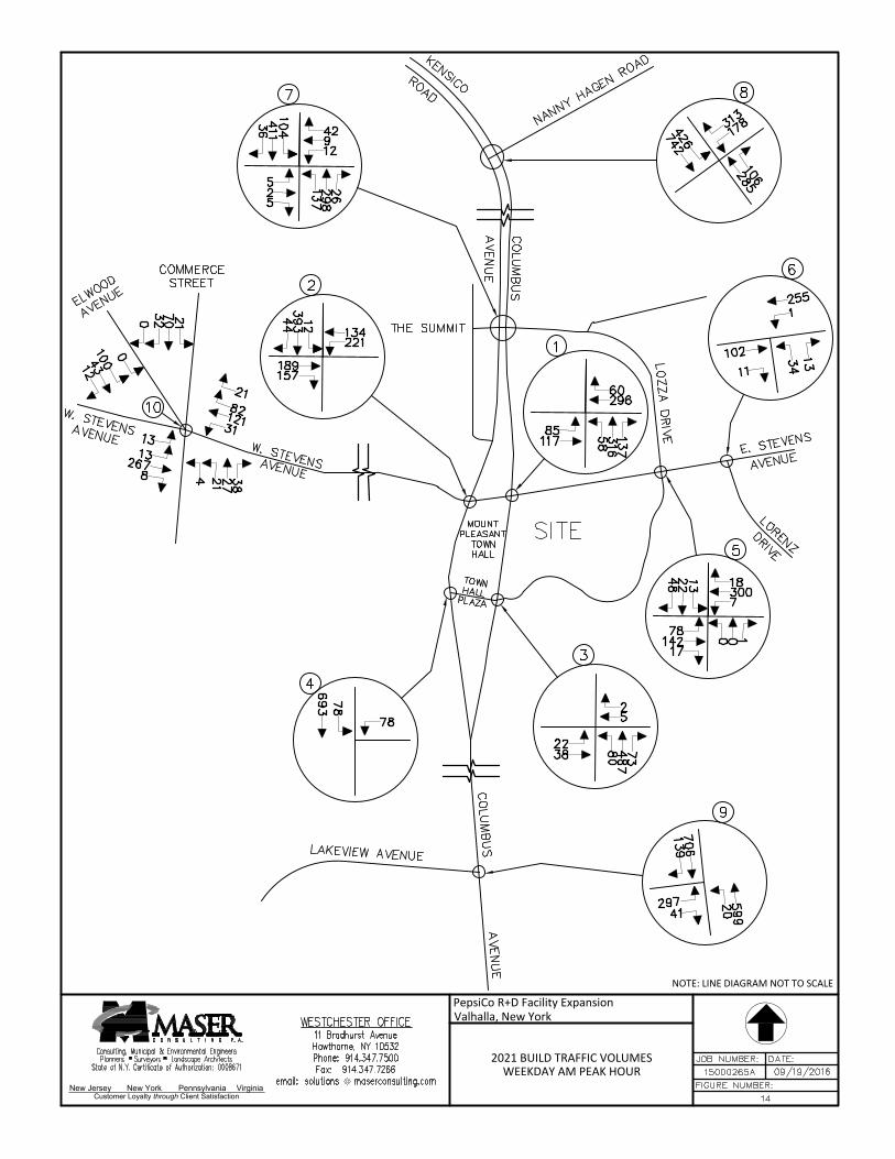
New Jersey New York Pennsylvania Virginia
Customer Loyalty through Client Satisfaction
NOTE: LINE DIAGRAM NOT TO SCALE
2021 BUILD TRAFFIC VOLUMESWEEKDAY AM PEAK HOUR
PepsiCo R+D Facility ExpansionValhalla, New York
AutoCAD SHX Text
7
AutoCAD SHX Text
12
AutoCAD SHX Text
9
AutoCAD SHX Text
42
AutoCAD SHX Text
5
AutoCAD SHX Text
2
AutoCAD SHX Text
5
AutoCAD SHX Text
137
AutoCAD SHX Text
298
AutoCAD SHX Text
26
AutoCAD SHX Text
104
AutoCAD SHX Text
411
AutoCAD SHX Text
36
AutoCAD SHX Text
5
AutoCAD SHX Text
7
AutoCAD SHX Text
300
AutoCAD SHX Text
18
AutoCAD SHX Text
78
AutoCAD SHX Text
142
AutoCAD SHX Text
17
AutoCAD SHX Text
0
AutoCAD SHX Text
0
AutoCAD SHX Text
1
AutoCAD SHX Text
13
AutoCAD SHX Text
22
AutoCAD SHX Text
48
AutoCAD SHX Text
1
AutoCAD SHX Text
296
AutoCAD SHX Text
60
AutoCAD SHX Text
85
AutoCAD SHX Text
117
AutoCAD SHX Text
58
AutoCAD SHX Text
316
AutoCAD SHX Text
137
AutoCAD SHX Text
3
AutoCAD SHX Text
5
AutoCAD SHX Text
2
AutoCAD SHX Text
22
AutoCAD SHX Text
38
AutoCAD SHX Text
80
AutoCAD SHX Text
487
AutoCAD SHX Text
73
AutoCAD SHX Text
2
AutoCAD SHX Text
221
AutoCAD SHX Text
134
AutoCAD SHX Text
189
AutoCAD SHX Text
157
AutoCAD SHX Text
12
AutoCAD SHX Text
393
AutoCAD SHX Text
44
AutoCAD SHX Text
4
AutoCAD SHX Text
78
AutoCAD SHX Text
78
AutoCAD SHX Text
693
AutoCAD SHX Text
6
AutoCAD SHX Text
1
AutoCAD SHX Text
255
AutoCAD SHX Text
102
AutoCAD SHX Text
11
AutoCAD SHX Text
34
AutoCAD SHX Text
13
AutoCAD SHX Text
10
AutoCAD SHX Text
31
AutoCAD SHX Text
121
AutoCAD SHX Text
82
AutoCAD SHX Text
13
AutoCAD SHX Text
267
AutoCAD SHX Text
8
AutoCAD SHX Text
4
AutoCAD SHX Text
27
AutoCAD SHX Text
38
AutoCAD SHX Text
21
AutoCAD SHX Text
70
AutoCAD SHX Text
32
AutoCAD SHX Text
706
AutoCAD SHX Text
139
AutoCAD SHX Text
297
AutoCAD SHX Text
41
AutoCAD SHX Text
20
AutoCAD SHX Text
599
AutoCAD SHX Text
9
AutoCAD SHX Text
8
AutoCAD SHX Text
FIGURE NUMBER:
AutoCAD SHX Text
DATE:
AutoCAD SHX Text
JOB NUMBER:
AutoCAD SHX Text
Consulting, Municipal & Environmental Engineers Planners Surveyors Landscape Architects State of N.Y. Certificate of Authorization: 0008671
AutoCAD SHX Text
15000265A
AutoCAD SHX Text
09/19/2016
AutoCAD SHX Text
WESTCHESTER OFFICE 11 Bradhurst Avenue Hawthorne, NY 10532 Phone: 914.347.7500 Fax: 914.347.7266 email: solutions @ maserconsulting.com@ maserconsulting.com maserconsulting.commaserconsulting.com
AutoCAD SHX Text
14
AutoCAD SHX Text
LOZZA DRIVE
AutoCAD SHX Text
E. STEVENS
AutoCAD SHX Text
LORENZ
AutoCAD SHX Text
DRIVE
AutoCAD SHX Text
MOUNT PLEASANT TOWN HALL
AutoCAD SHX Text
TOWN HALL PLAZA
AutoCAD SHX Text
W. STEVENS AVENUE
AutoCAD SHX Text
THE SUMMIT
AutoCAD SHX Text
NANNY HAGEN ROAD
AutoCAD SHX Text
SITE
AutoCAD SHX Text
COLUMBUS
AutoCAD SHX Text
LAKEVIEW AVENUE
AutoCAD SHX Text
W. STEVENS AVENUE
AutoCAD SHX Text
ELWOOD AVENUE
AutoCAD SHX Text
COMMERCE STREET
AutoCAD SHX Text
COLUMBUS AVENUE
AutoCAD SHX Text
KENSICO ROAD
AutoCAD SHX Text
AVENUE
AutoCAD SHX Text
AVENUE
AutoCAD SHX Text
178
AutoCAD SHX Text
313
AutoCAD SHX Text
285
AutoCAD SHX Text
106
AutoCAD SHX Text
426
AutoCAD SHX Text
742
AutoCAD SHX Text
13
AutoCAD SHX Text
21
AutoCAD SHX Text
21
AutoCAD SHX Text
0
AutoCAD SHX Text
43
AutoCAD SHX Text
12
AutoCAD SHX Text
100
AutoCAD SHX Text
0
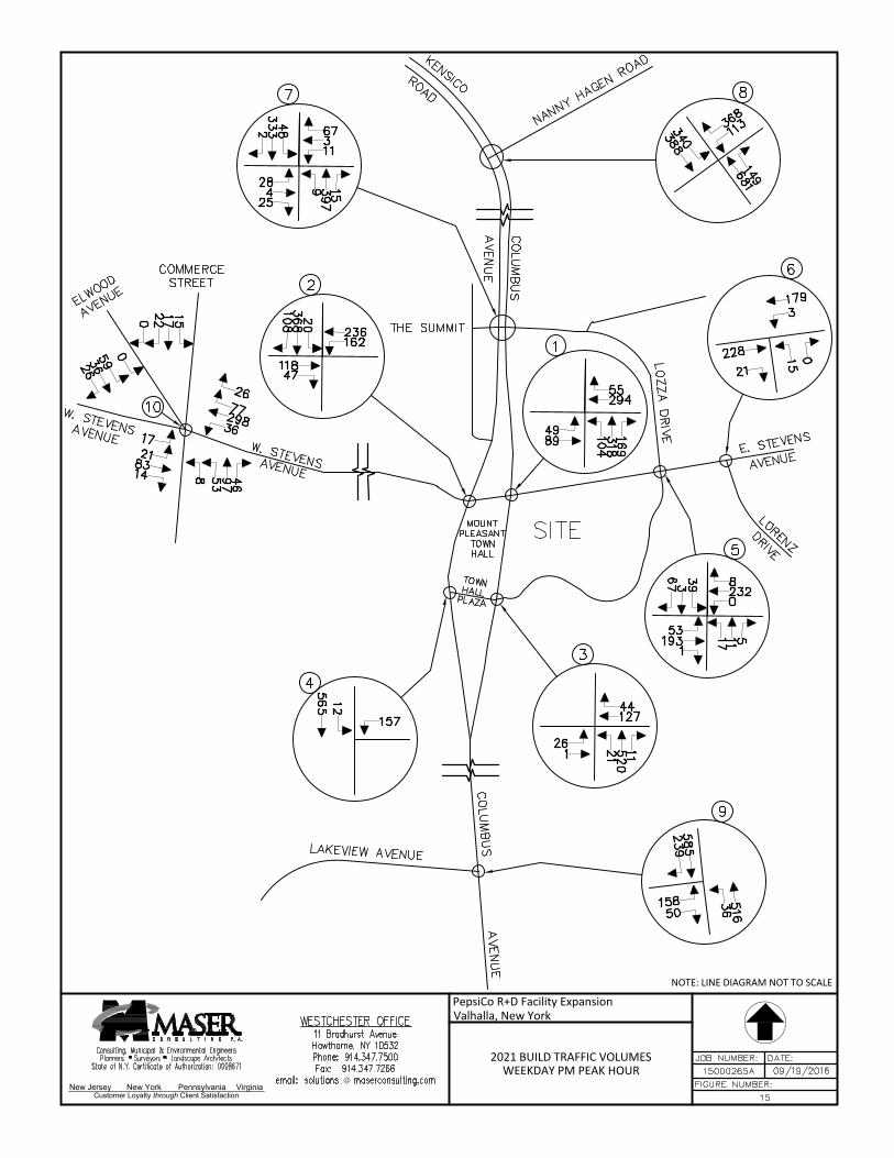
New Jersey New York Pennsylvania Virginia
Customer Loyalty through Client Satisfaction
NOTE: LINE DIAGRAM NOT TO SCALE
2021 BUILD TRAFFIC VOLUMESWEEKDAY PM PEAK HOUR
PepsiCo R+D Facility ExpansionValhalla, New York
AutoCAD SHX Text
7
AutoCAD SHX Text
11
AutoCAD SHX Text
3
AutoCAD SHX Text
67
AutoCAD SHX Text
28
AutoCAD SHX Text
4
AutoCAD SHX Text
25
AutoCAD SHX Text
9
AutoCAD SHX Text
397
AutoCAD SHX Text
15
AutoCAD SHX Text
48
AutoCAD SHX Text
333
AutoCAD SHX Text
2
AutoCAD SHX Text
5
AutoCAD SHX Text
0
AutoCAD SHX Text
232
AutoCAD SHX Text
8
AutoCAD SHX Text
53
AutoCAD SHX Text
193
AutoCAD SHX Text
1
AutoCAD SHX Text
17
AutoCAD SHX Text
11
AutoCAD SHX Text
5
AutoCAD SHX Text
39
AutoCAD SHX Text
3
AutoCAD SHX Text
67
AutoCAD SHX Text
1
AutoCAD SHX Text
294
AutoCAD SHX Text
55
AutoCAD SHX Text
49
AutoCAD SHX Text
89
AutoCAD SHX Text
104
AutoCAD SHX Text
318
AutoCAD SHX Text
169
AutoCAD SHX Text
3
AutoCAD SHX Text
127
AutoCAD SHX Text
44
AutoCAD SHX Text
26
AutoCAD SHX Text
1
AutoCAD SHX Text
21
AutoCAD SHX Text
520
AutoCAD SHX Text
11
AutoCAD SHX Text
2
AutoCAD SHX Text
162
AutoCAD SHX Text
236
AutoCAD SHX Text
118
AutoCAD SHX Text
47
AutoCAD SHX Text
20
AutoCAD SHX Text
368
AutoCAD SHX Text
108
AutoCAD SHX Text
4
AutoCAD SHX Text
157
AutoCAD SHX Text
12
AutoCAD SHX Text
565
AutoCAD SHX Text
6
AutoCAD SHX Text
3
AutoCAD SHX Text
179
AutoCAD SHX Text
228
AutoCAD SHX Text
21
AutoCAD SHX Text
15
AutoCAD SHX Text
0
AutoCAD SHX Text
10
AutoCAD SHX Text
36
AutoCAD SHX Text
298
AutoCAD SHX Text
77
AutoCAD SHX Text
17
AutoCAD SHX Text
83
AutoCAD SHX Text
14
AutoCAD SHX Text
8
AutoCAD SHX Text
97
AutoCAD SHX Text
46
AutoCAD SHX Text
15
AutoCAD SHX Text
17
AutoCAD SHX Text
22
AutoCAD SHX Text
585
AutoCAD SHX Text
239
AutoCAD SHX Text
158
AutoCAD SHX Text
50
AutoCAD SHX Text
36
AutoCAD SHX Text
516
AutoCAD SHX Text
9
AutoCAD SHX Text
8
AutoCAD SHX Text
FIGURE NUMBER:
AutoCAD SHX Text
DATE:
AutoCAD SHX Text
JOB NUMBER:
AutoCAD SHX Text
Consulting, Municipal & Environmental Engineers Planners Surveyors Landscape Architects State of N.Y. Certificate of Authorization: 0008671
AutoCAD SHX Text
15000265A
AutoCAD SHX Text
09/19/2016
AutoCAD SHX Text
WESTCHESTER OFFICE 11 Bradhurst Avenue Hawthorne, NY 10532 Phone: 914.347.7500 Fax: 914.347.7266 email: solutions @ maserconsulting.com@ maserconsulting.com maserconsulting.commaserconsulting.com
AutoCAD SHX Text
15
AutoCAD SHX Text
LOZZA DRIVE
AutoCAD SHX Text
E. STEVENS
AutoCAD SHX Text
LORENZ
AutoCAD SHX Text
DRIVE
AutoCAD SHX Text
MOUNT PLEASANT TOWN HALL
AutoCAD SHX Text
TOWN HALL PLAZA
AutoCAD SHX Text
W. STEVENS AVENUE
AutoCAD SHX Text
THE SUMMIT
AutoCAD SHX Text
NANNY HAGEN ROAD
AutoCAD SHX Text
SITE
AutoCAD SHX Text
COLUMBUS
AutoCAD SHX Text
LAKEVIEW AVENUE
AutoCAD SHX Text
W. STEVENS AVENUE
AutoCAD SHX Text
ELWOOD AVENUE
AutoCAD SHX Text
COMMERCE STREET
AutoCAD SHX Text
COLUMBUS AVENUE
AutoCAD SHX Text
KENSICO ROAD
AutoCAD SHX Text
AVENUE
AutoCAD SHX Text
AVENUE
AutoCAD SHX Text
113
AutoCAD SHX Text
368
AutoCAD SHX Text
681
AutoCAD SHX Text
149
AutoCAD SHX Text
340
AutoCAD SHX Text
388
AutoCAD SHX Text
21
AutoCAD SHX Text
26
AutoCAD SHX Text
53
AutoCAD SHX Text
0
AutoCAD SHX Text
36
AutoCAD SHX Text
26
AutoCAD SHX Text
59
AutoCAD SHX Text
0
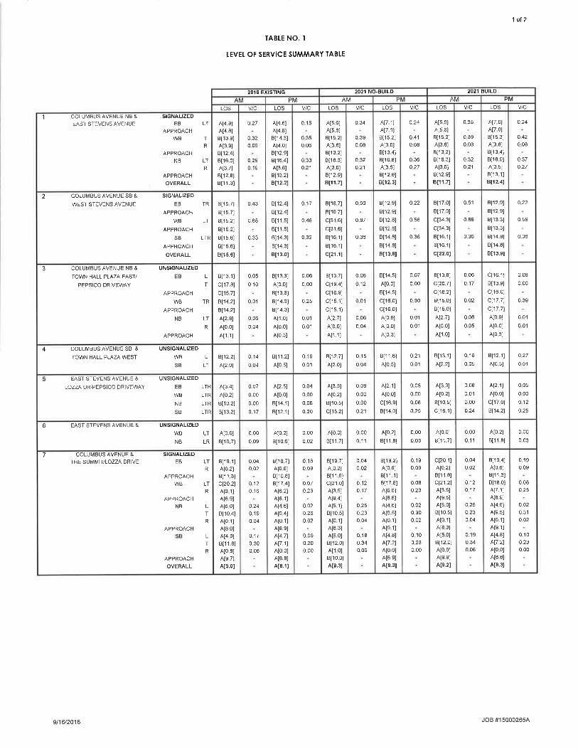
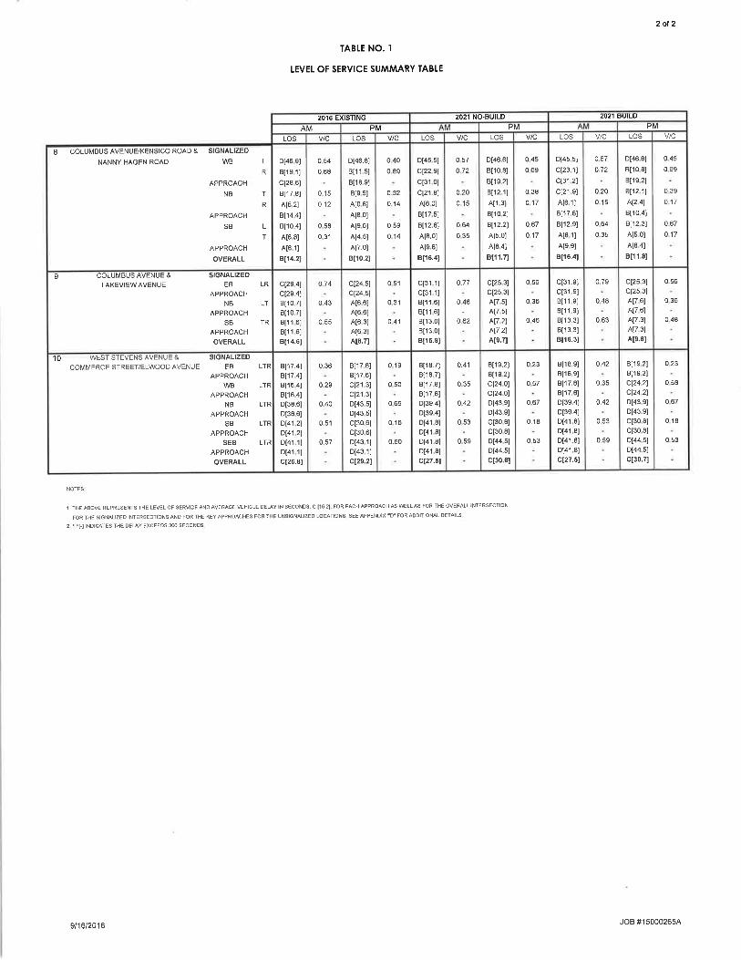
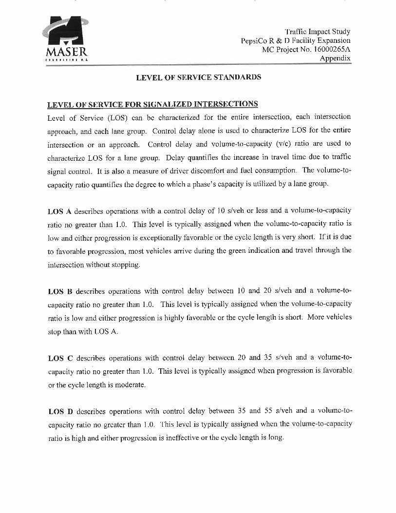
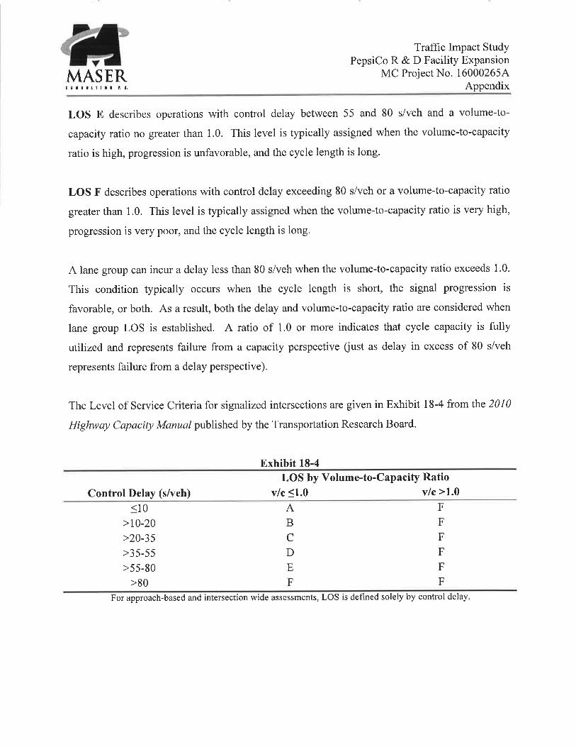
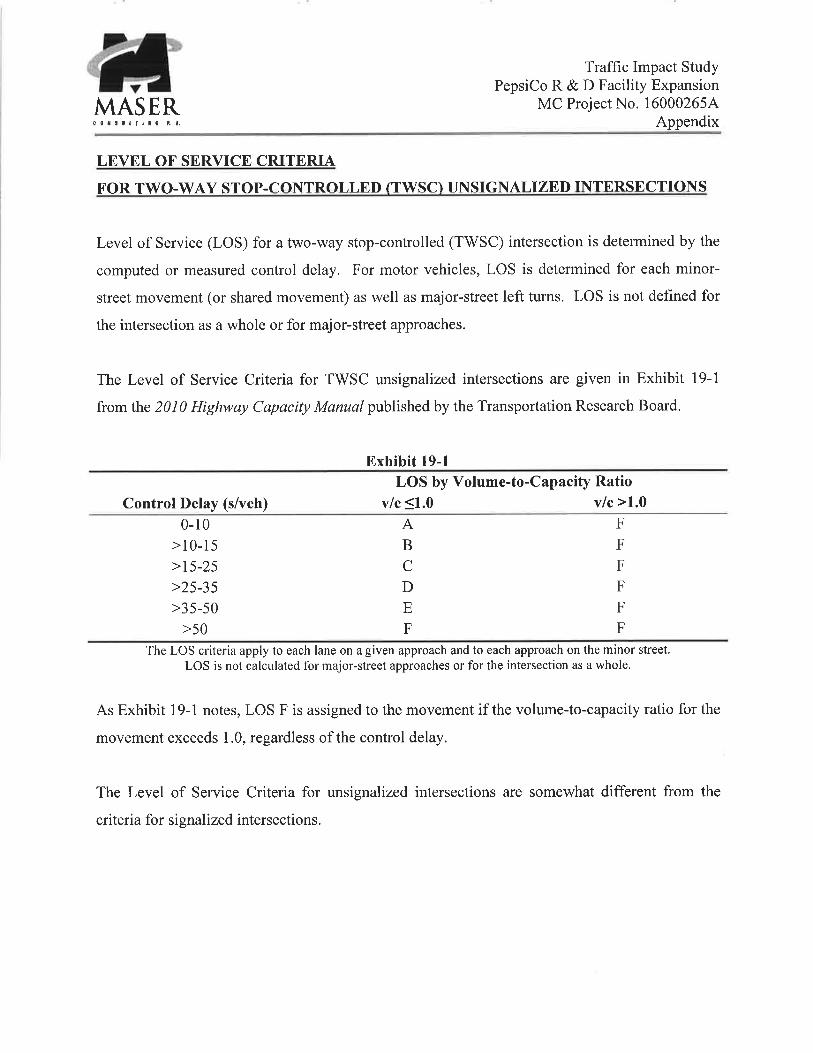
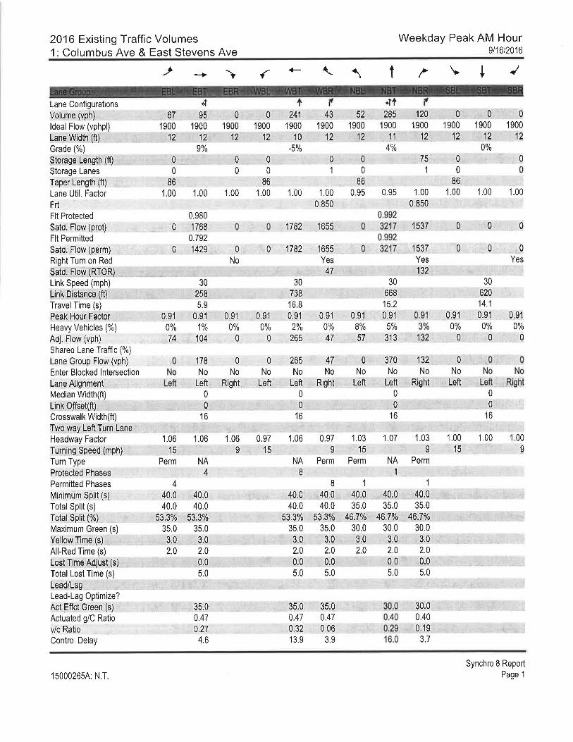

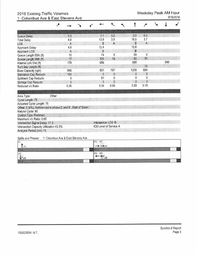

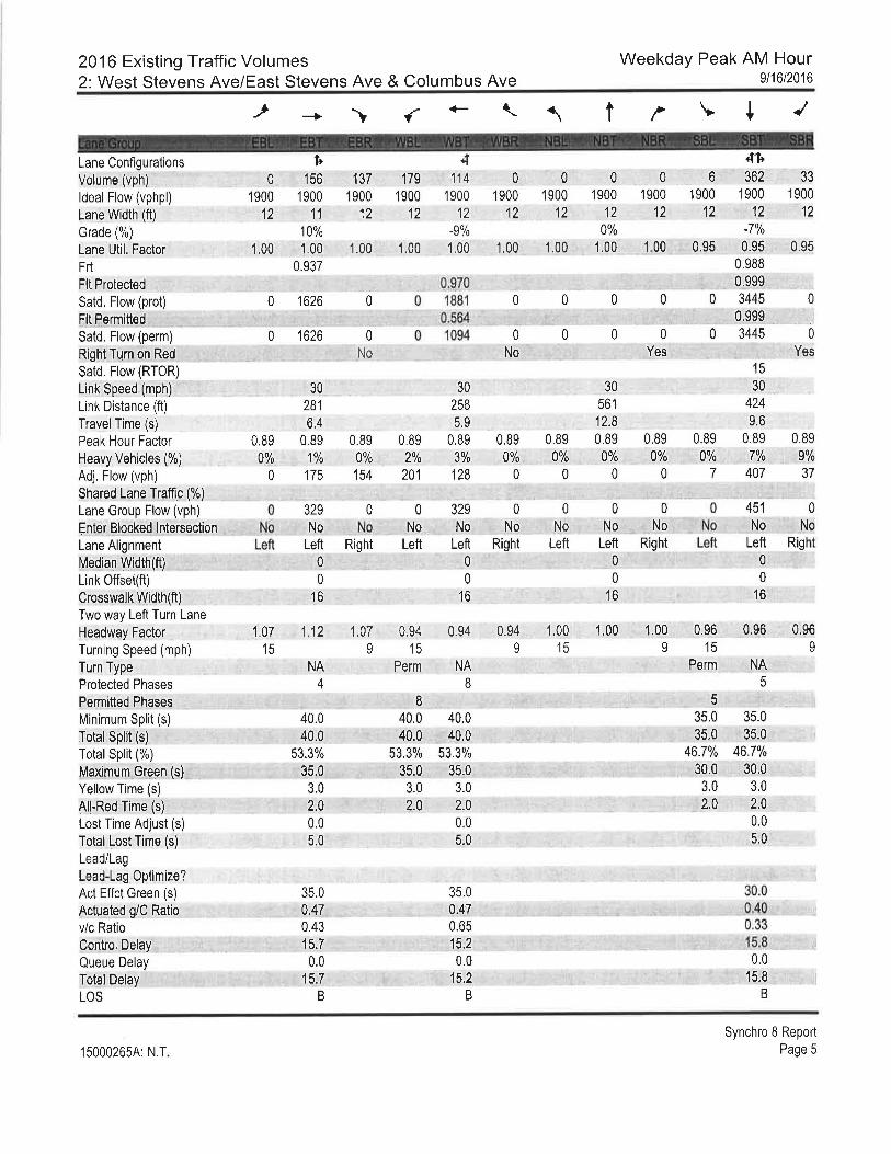
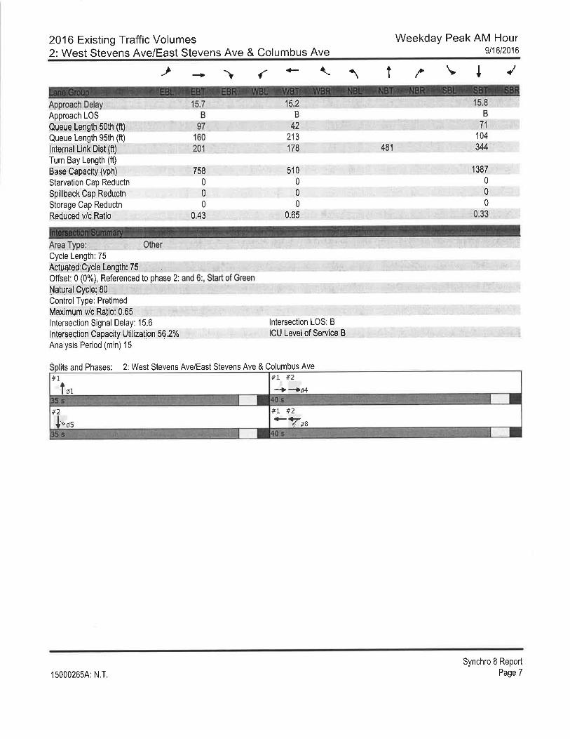
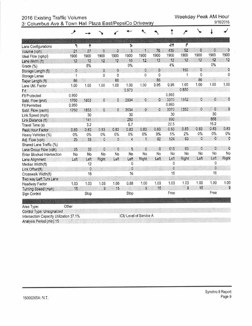

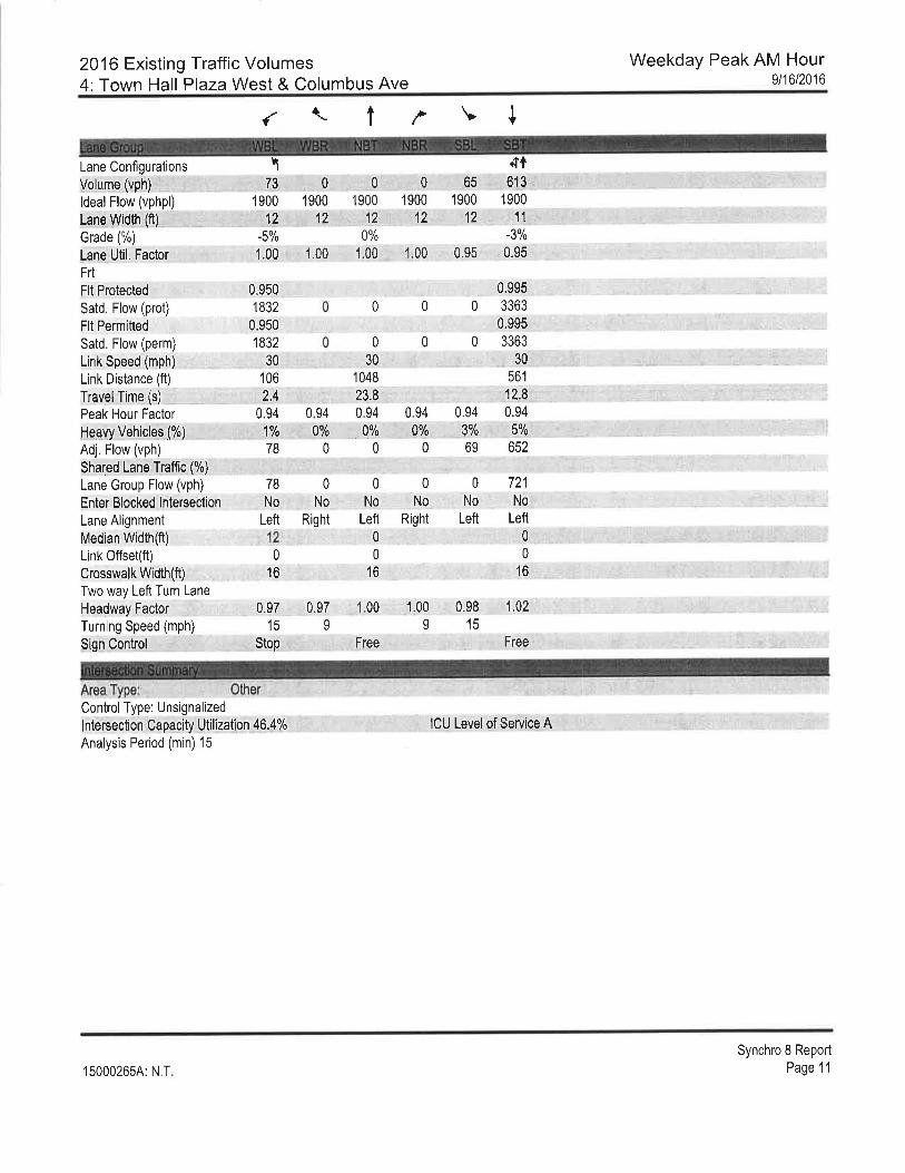
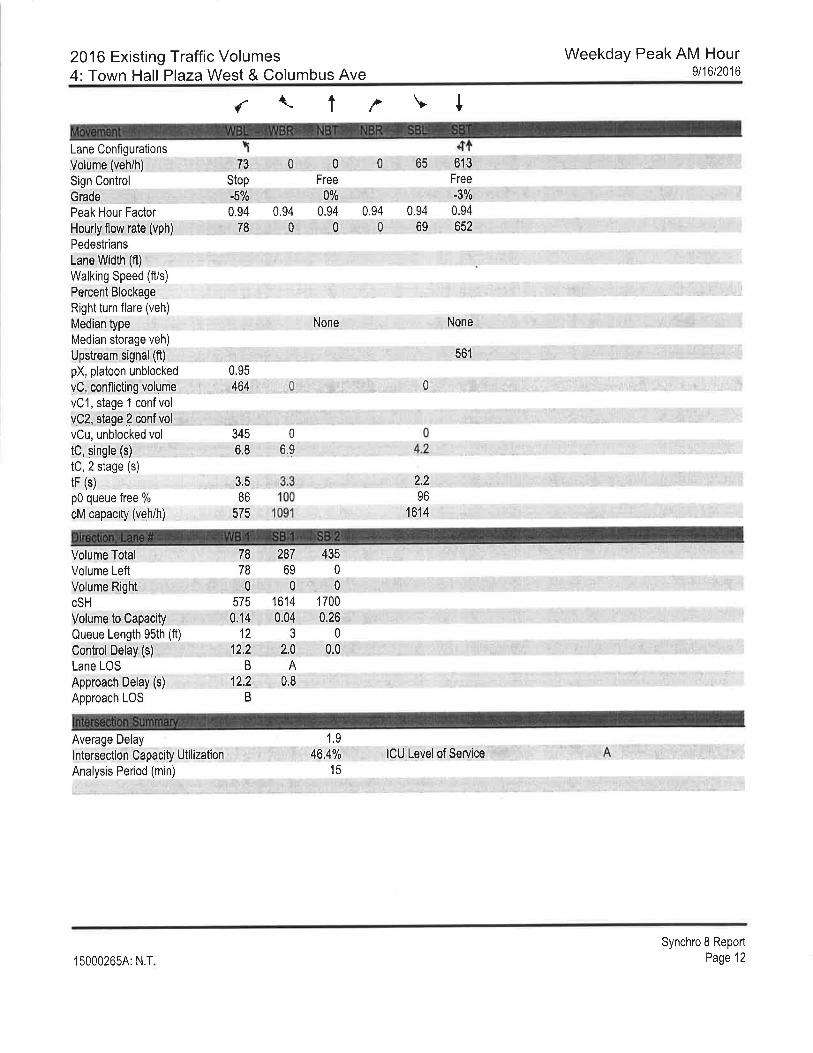


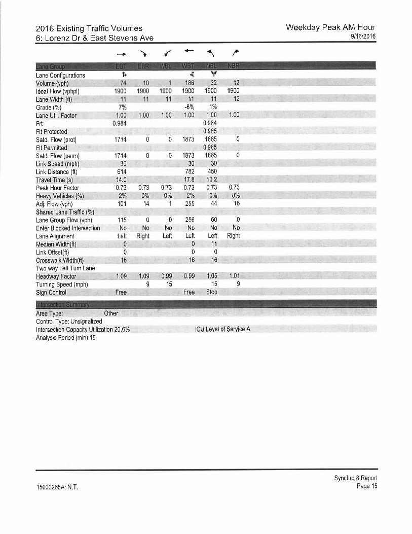
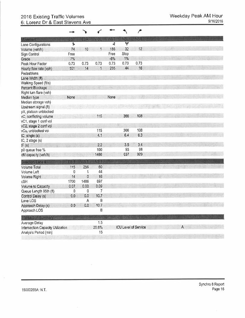
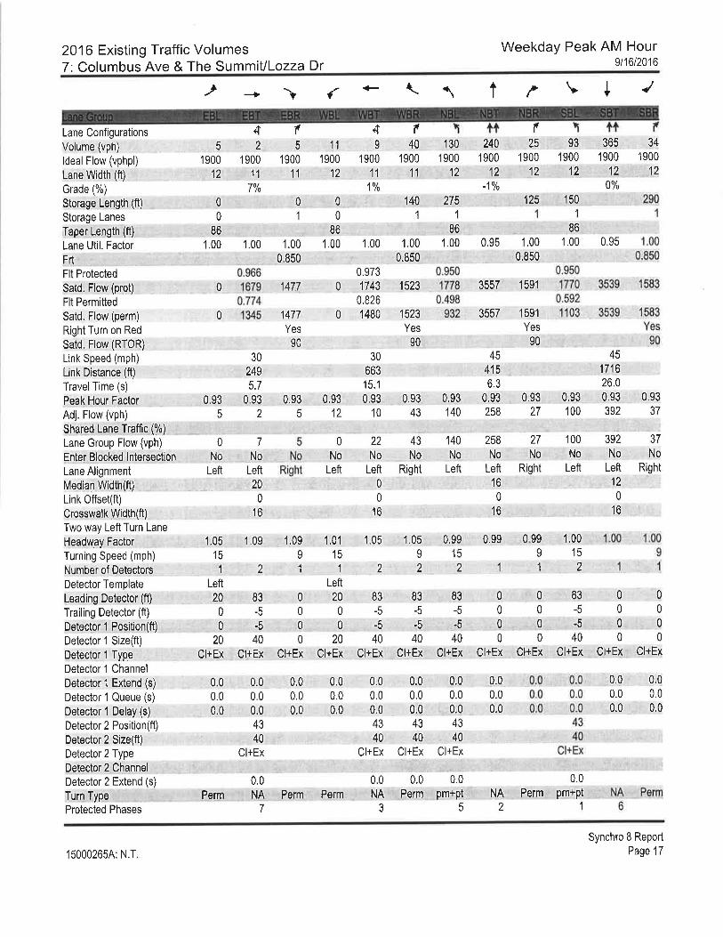
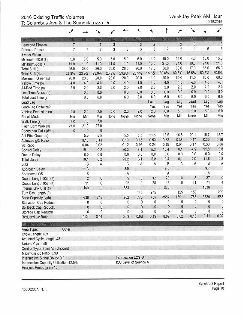
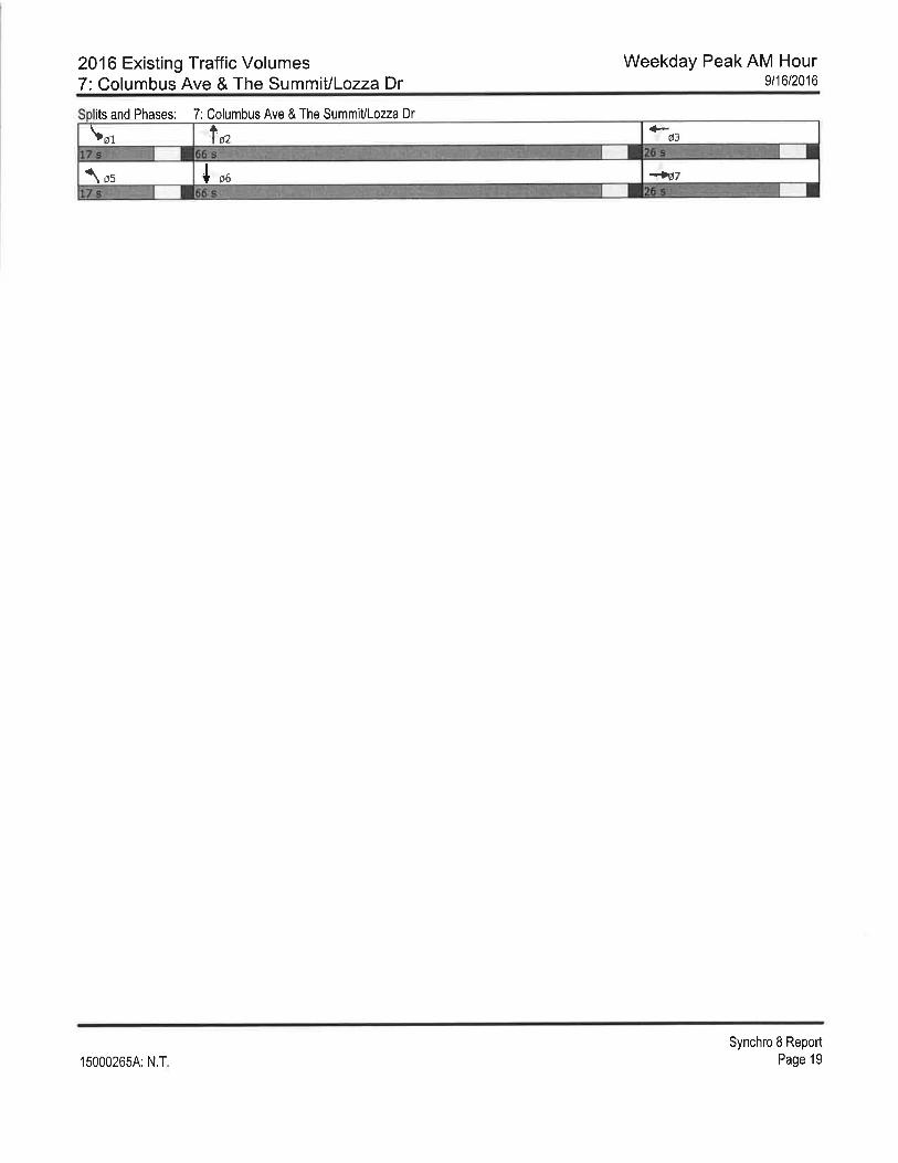
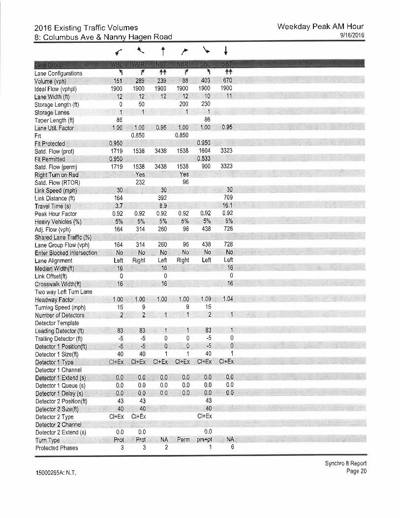
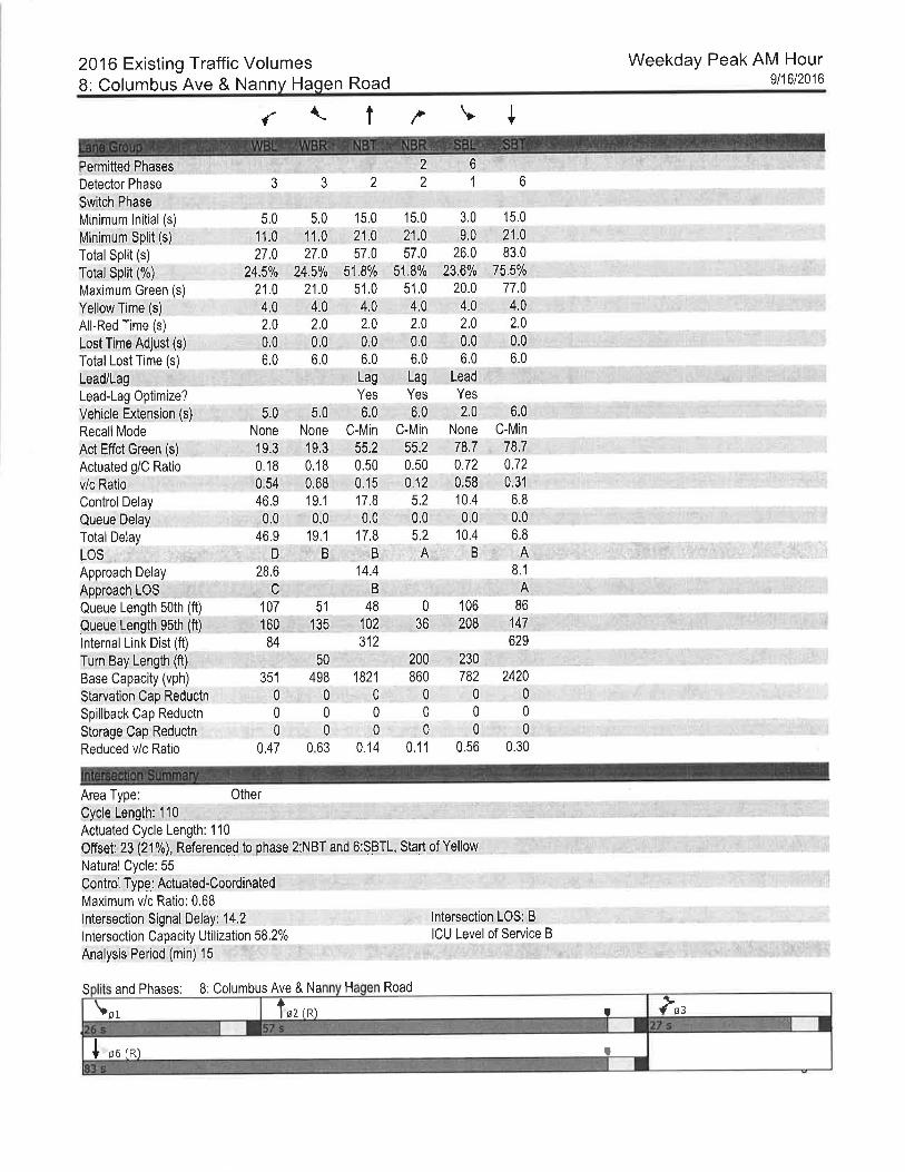
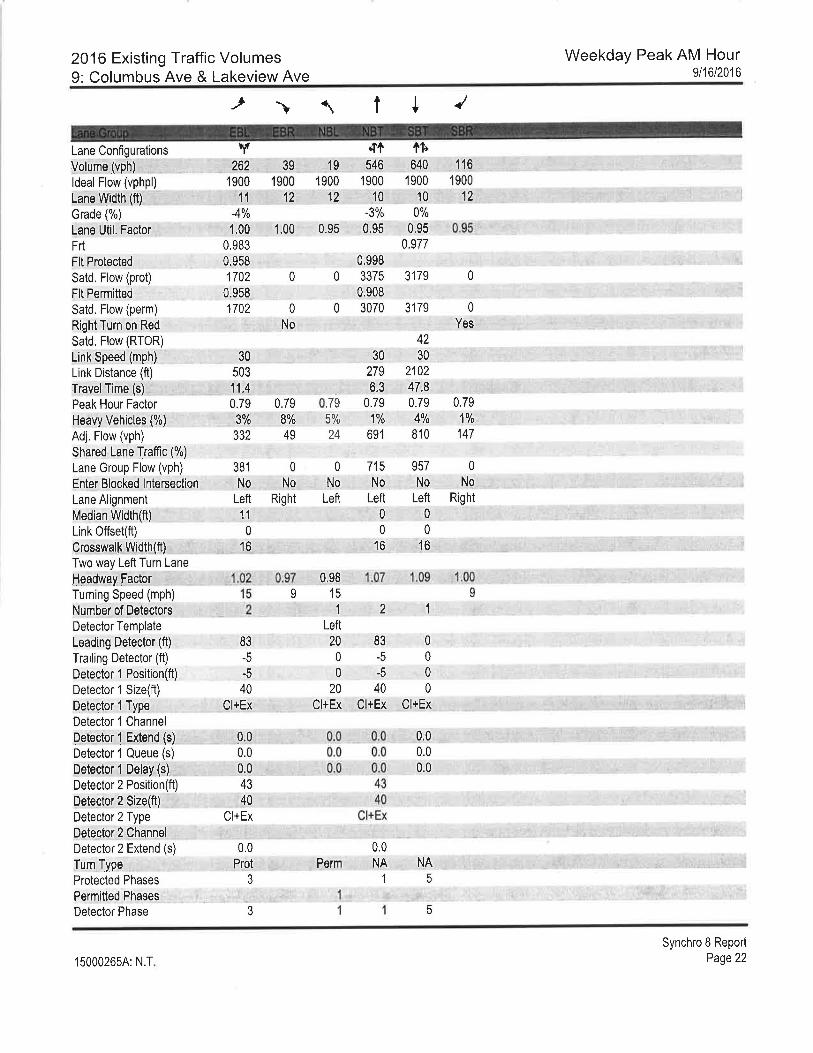

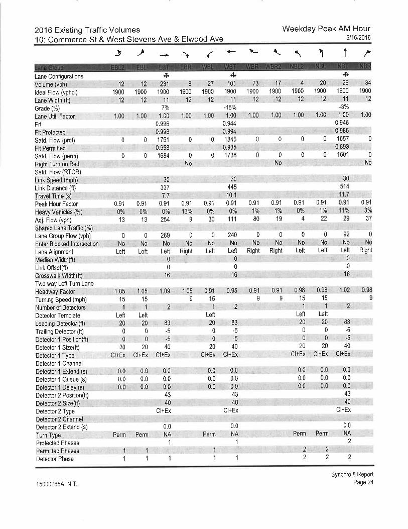
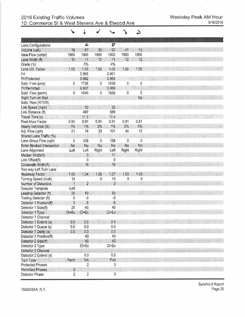
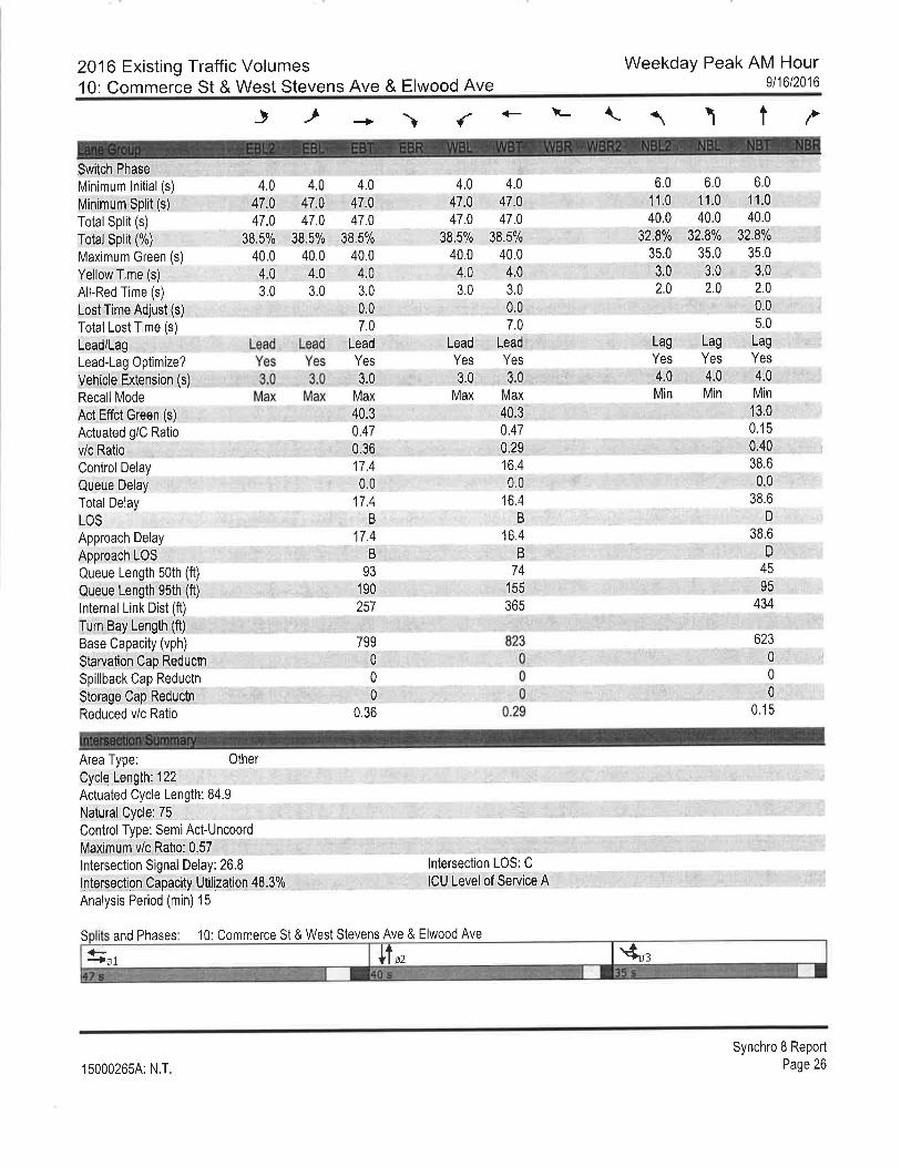

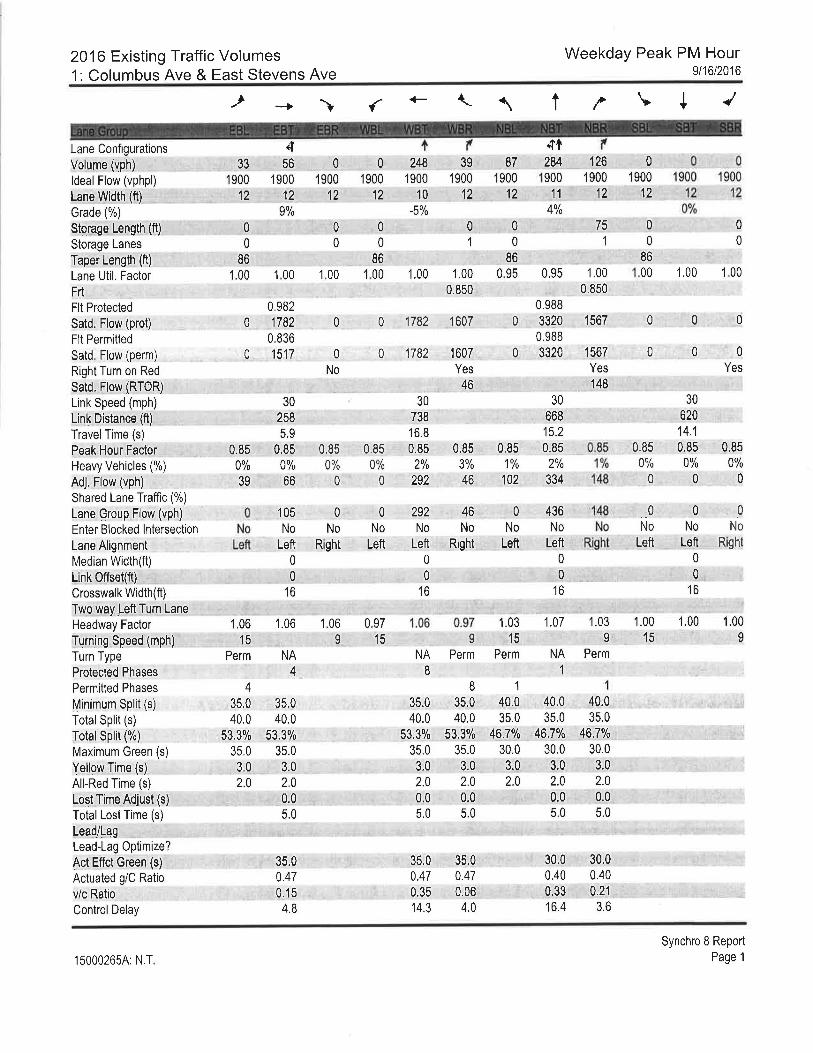

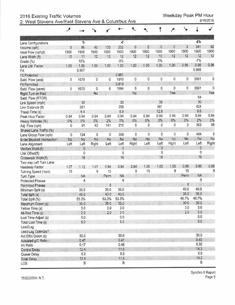
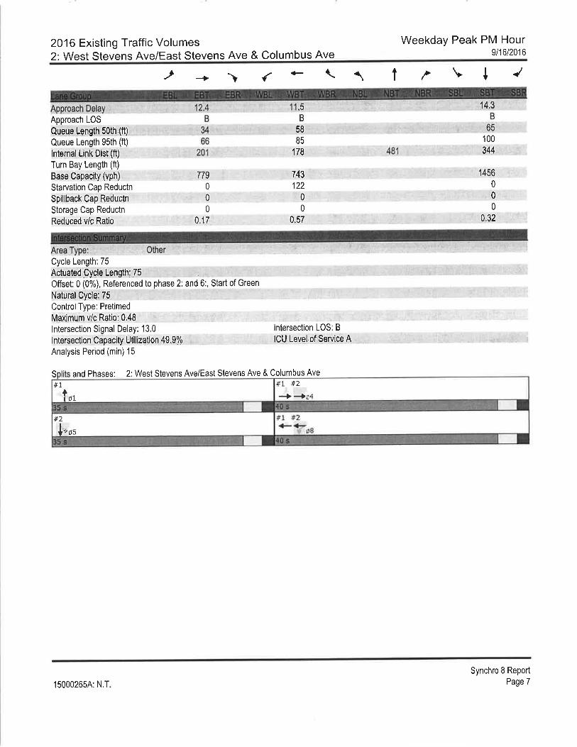
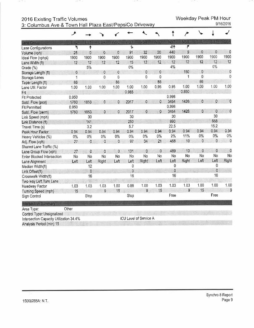
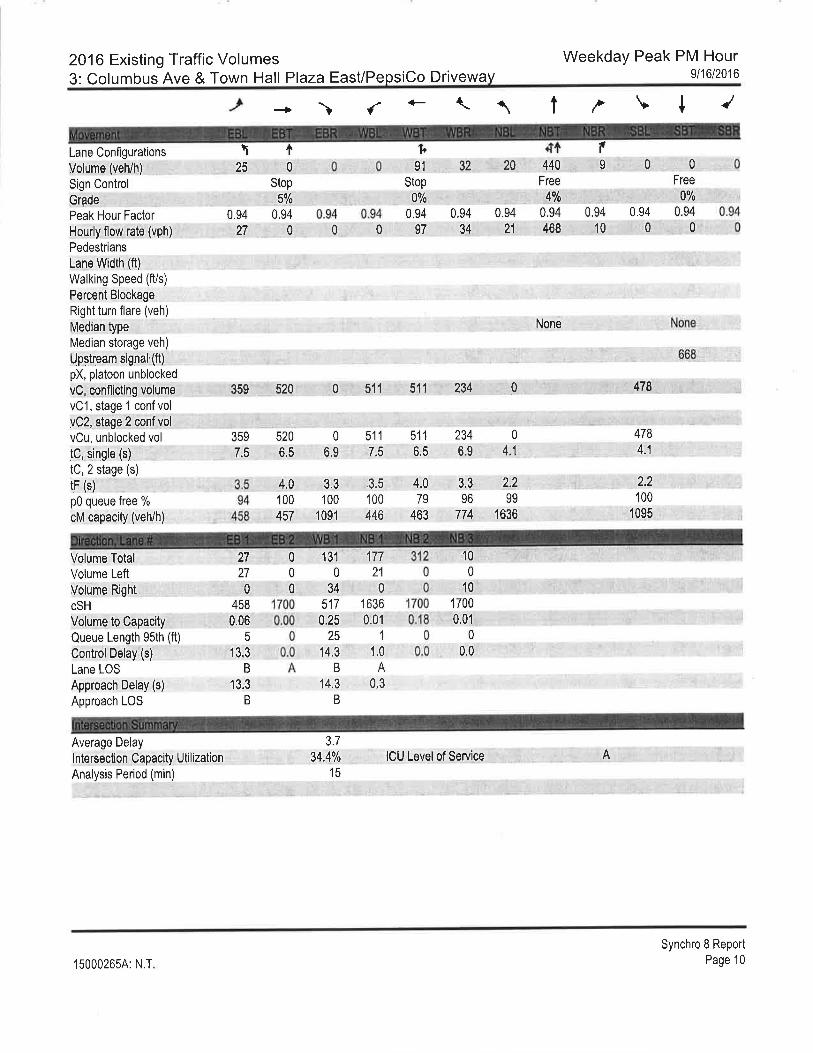
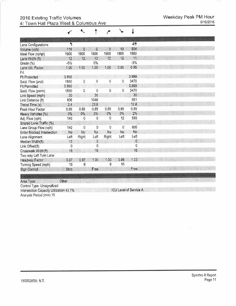
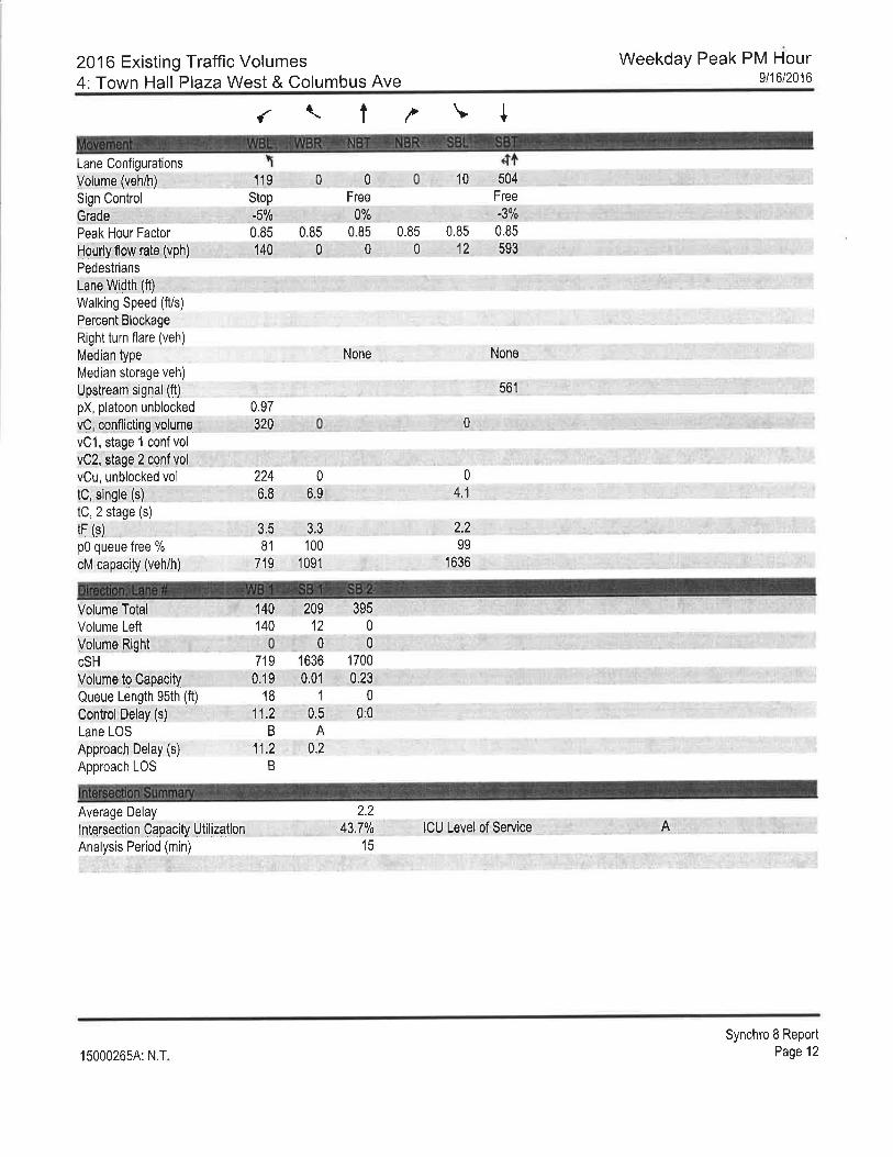


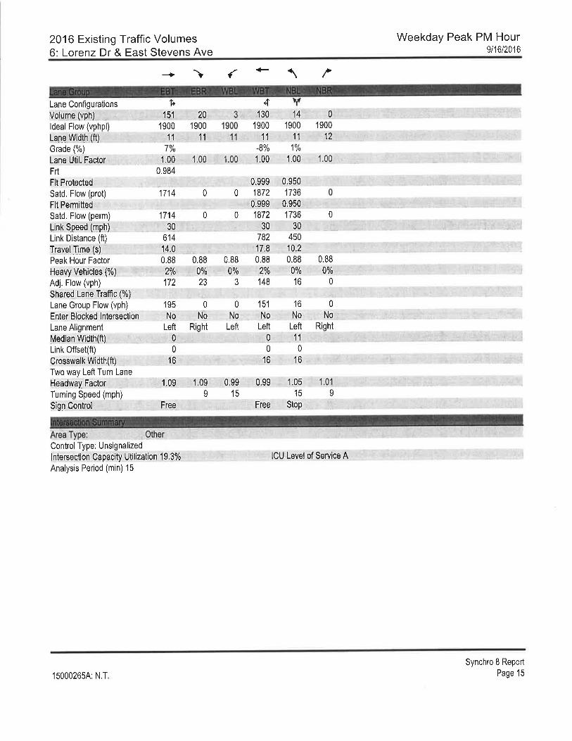


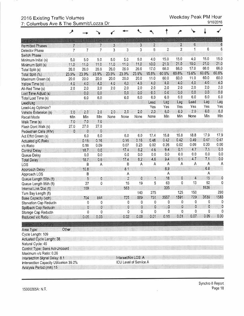

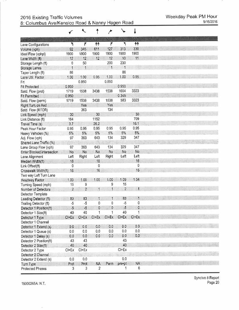
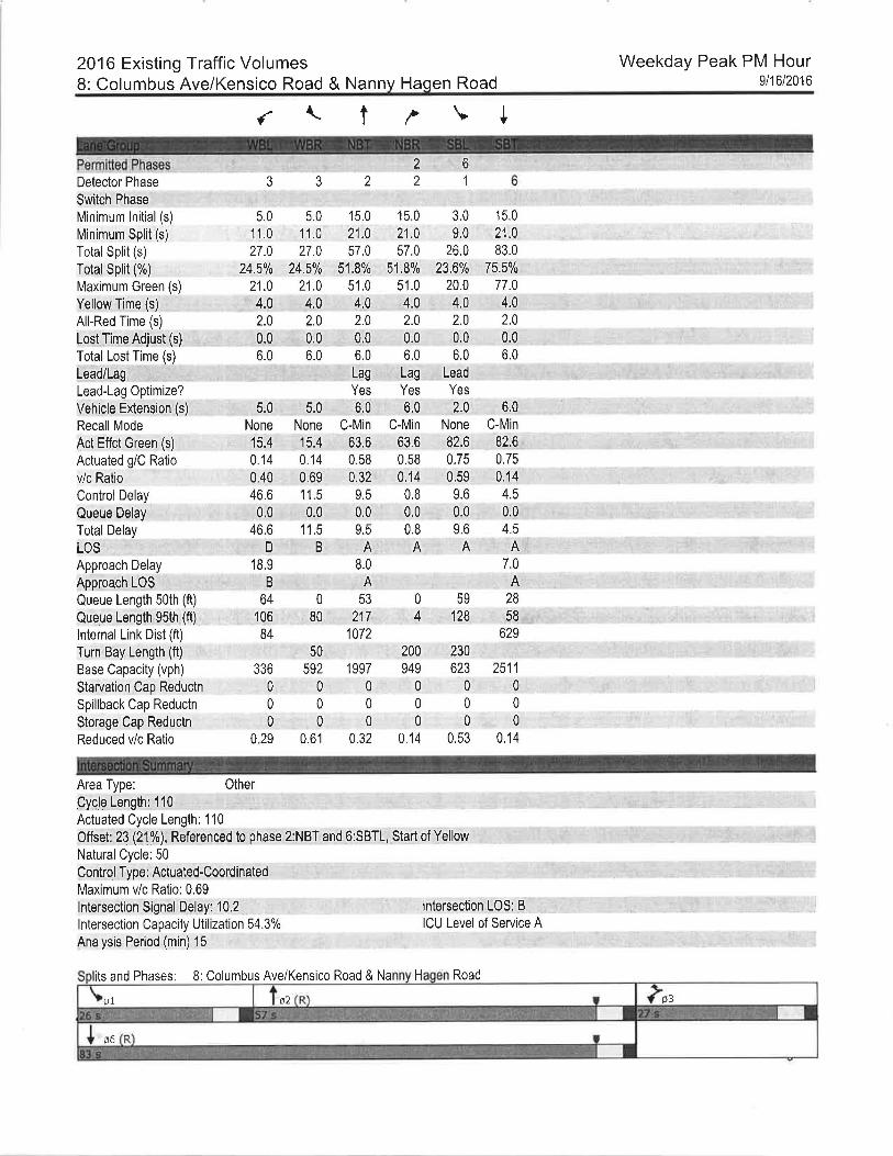


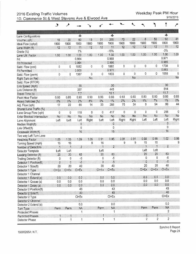
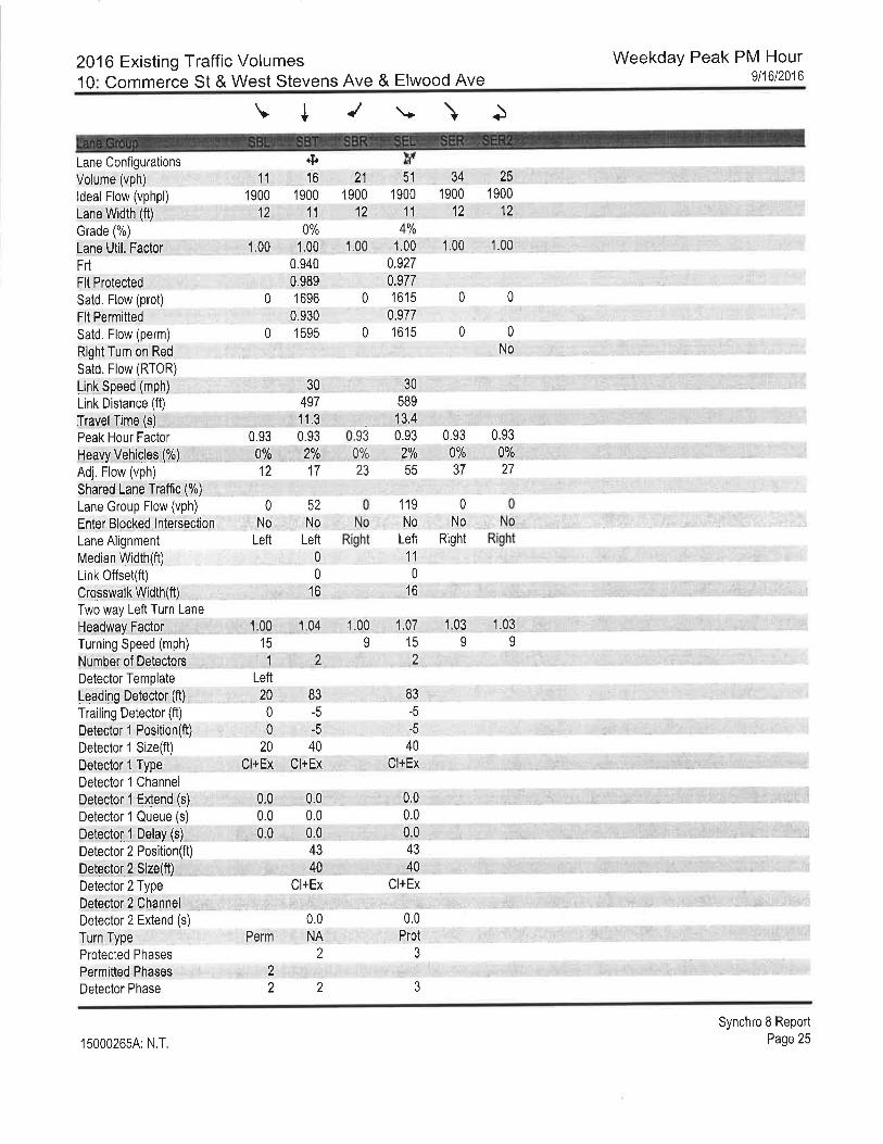
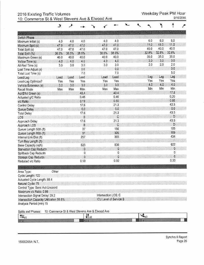
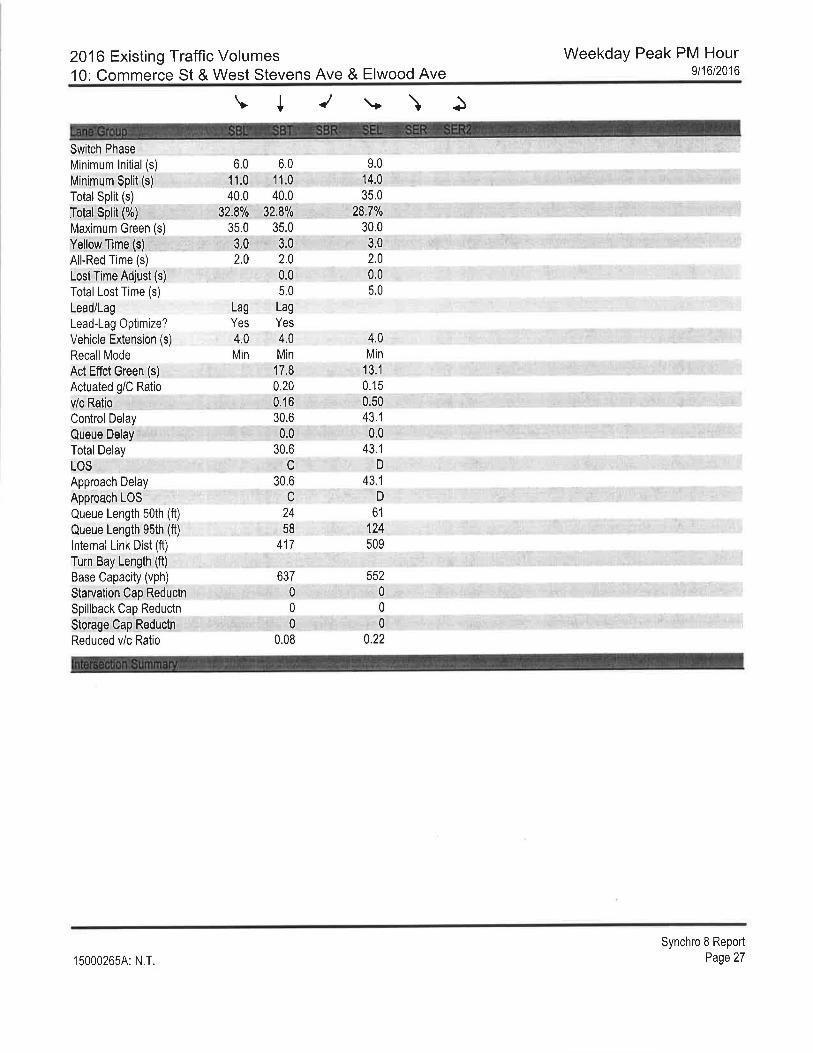
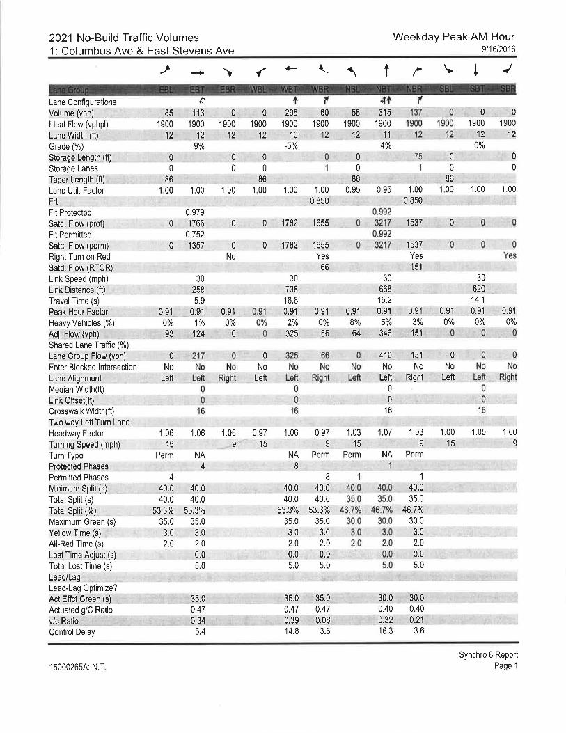

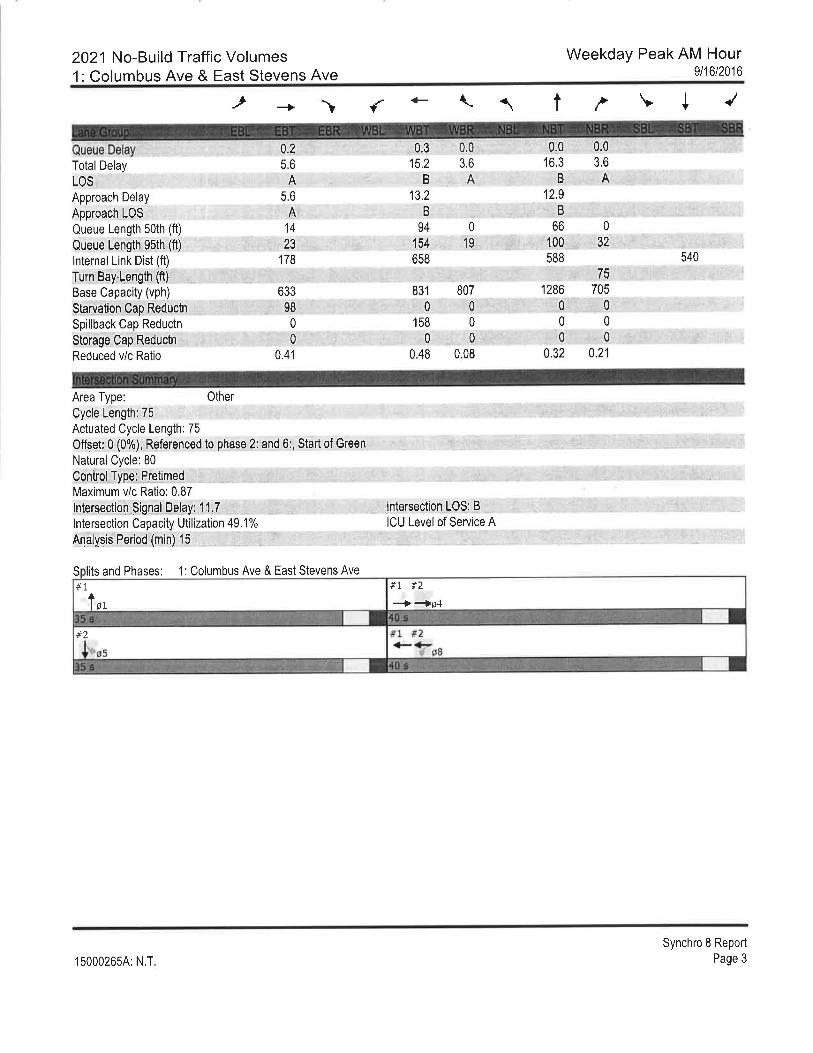
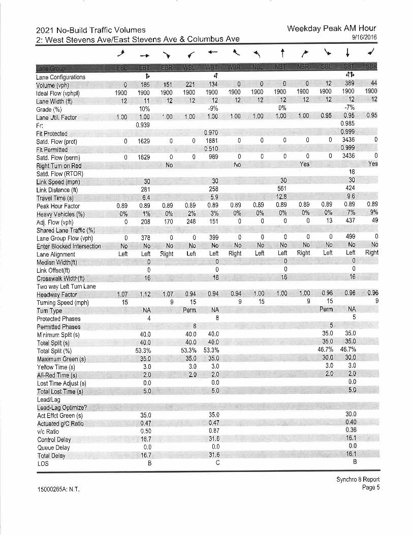


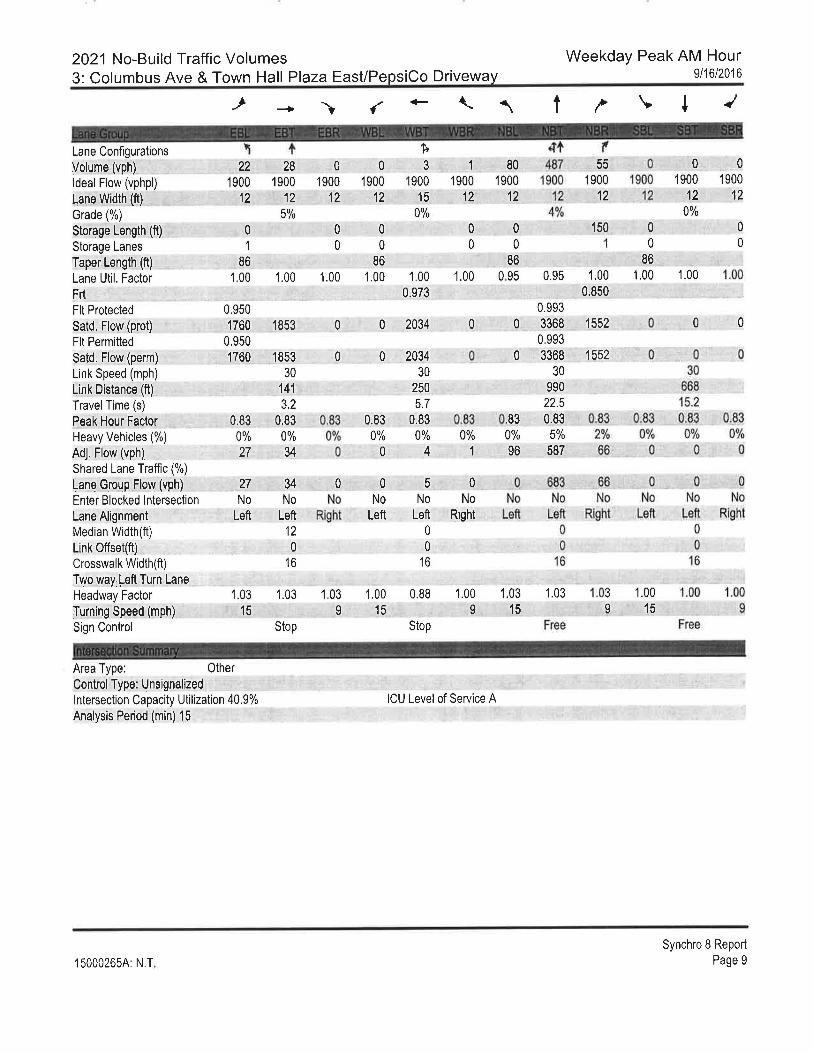

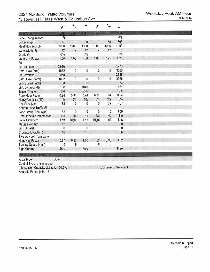
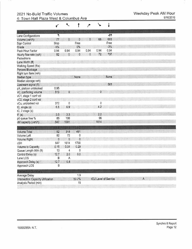


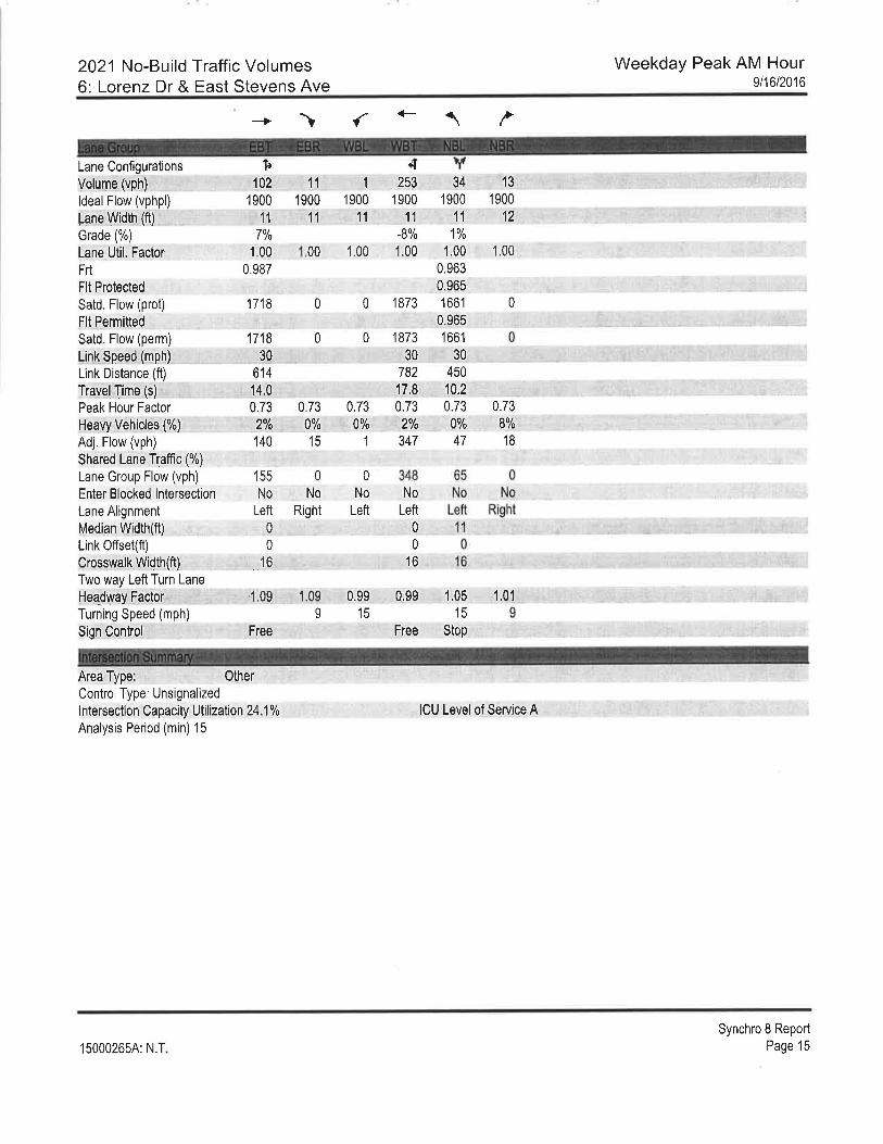
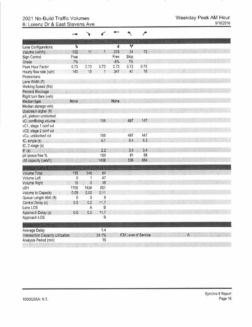
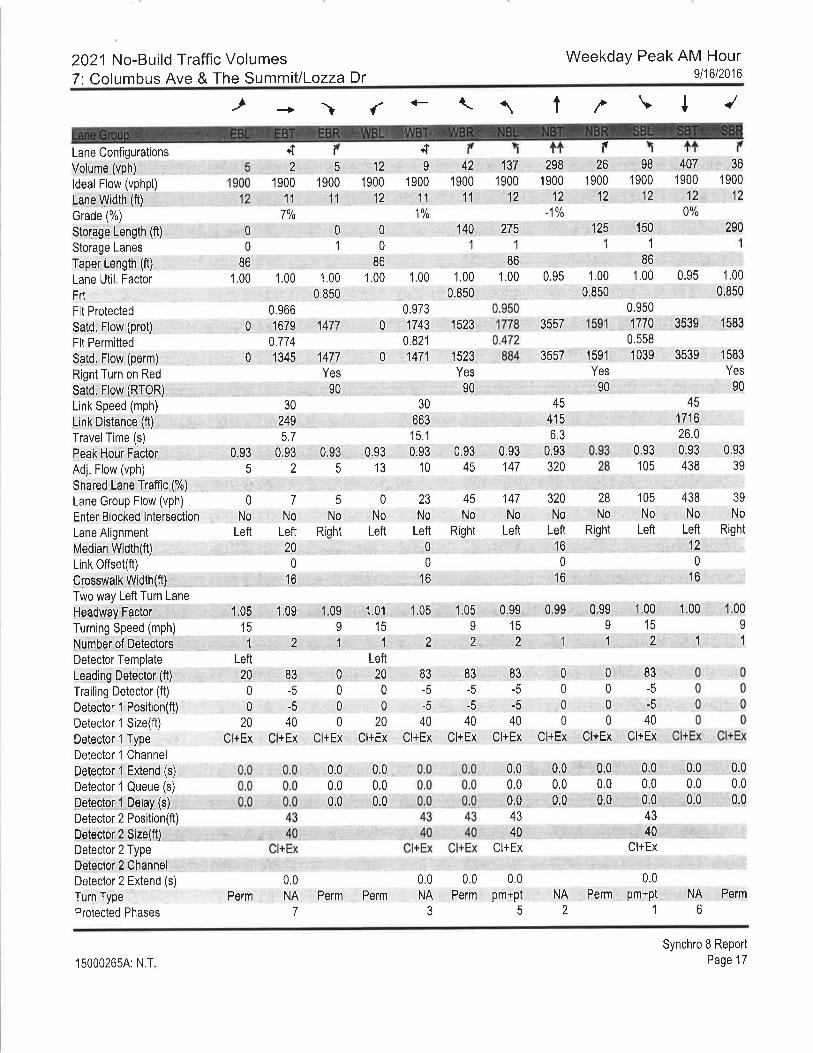
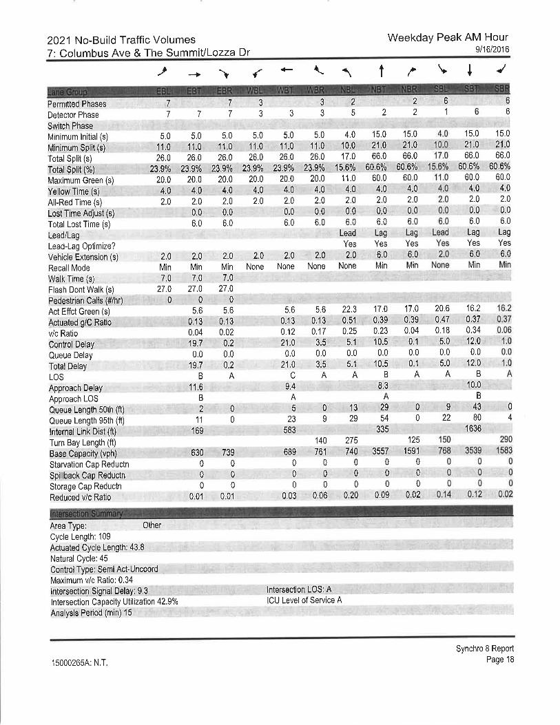

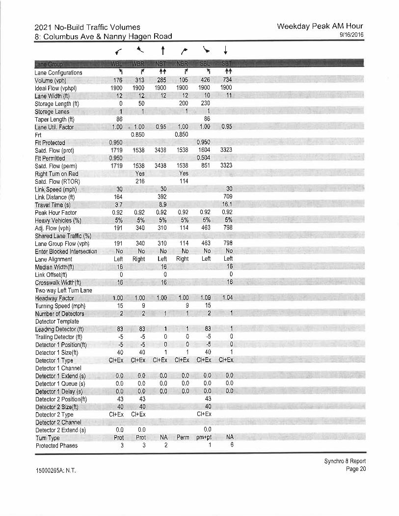
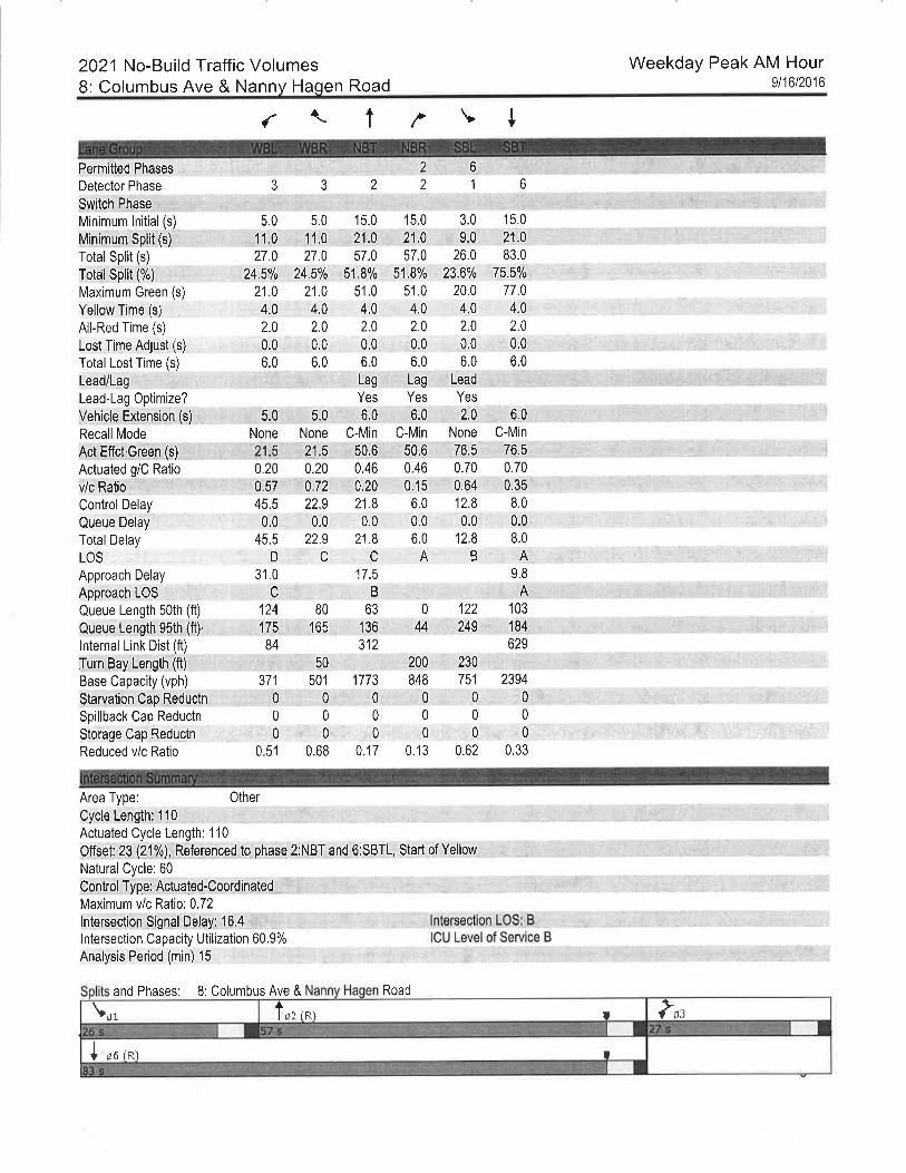

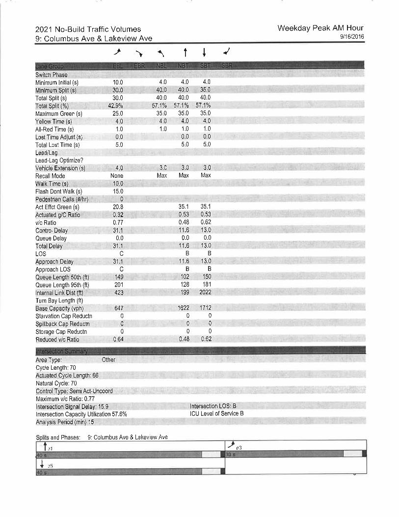
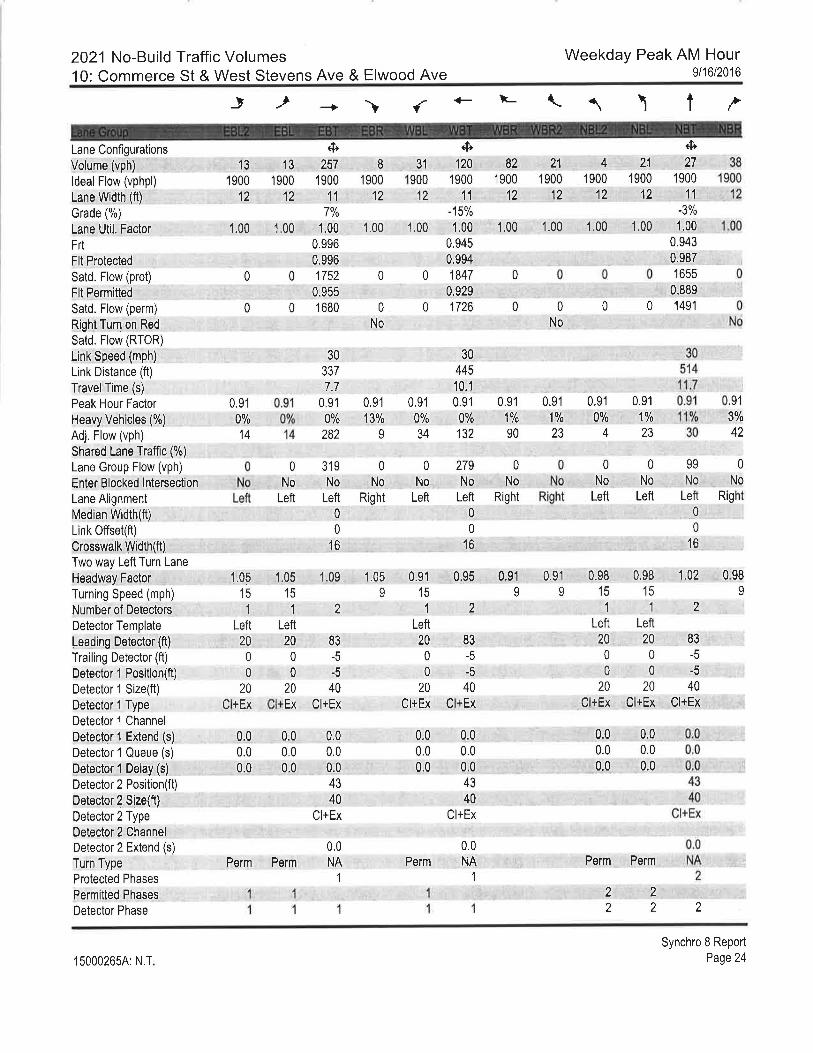
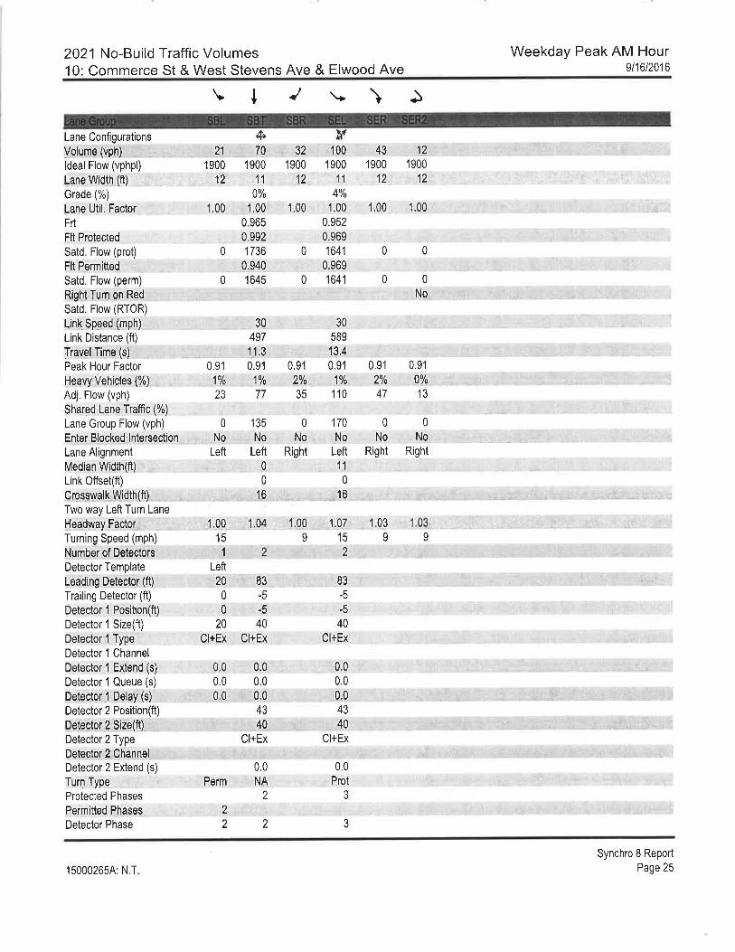
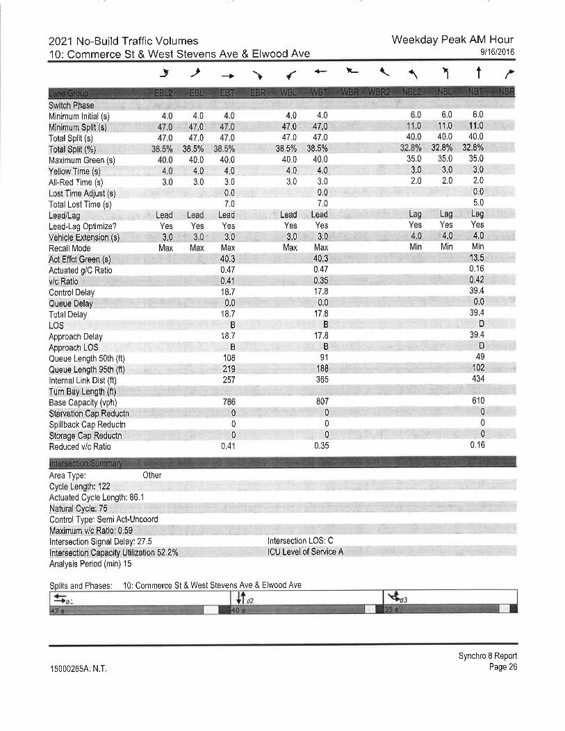
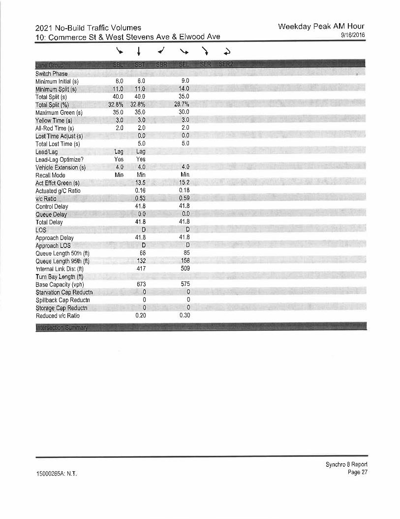
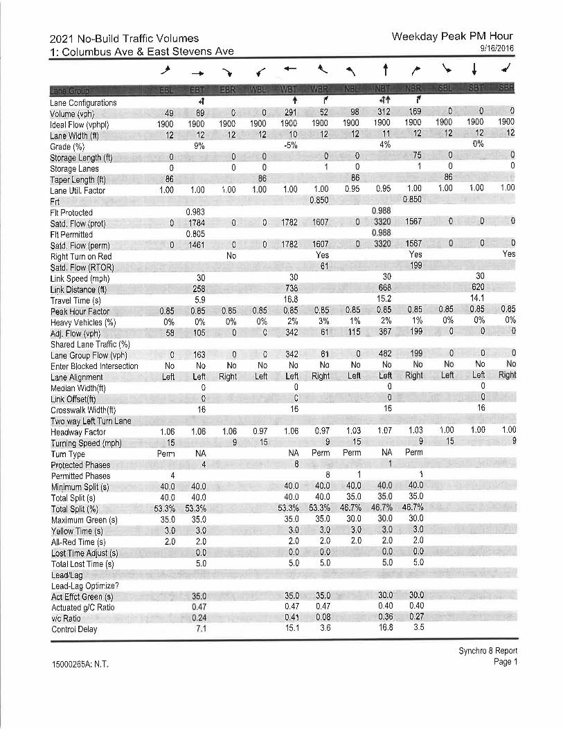
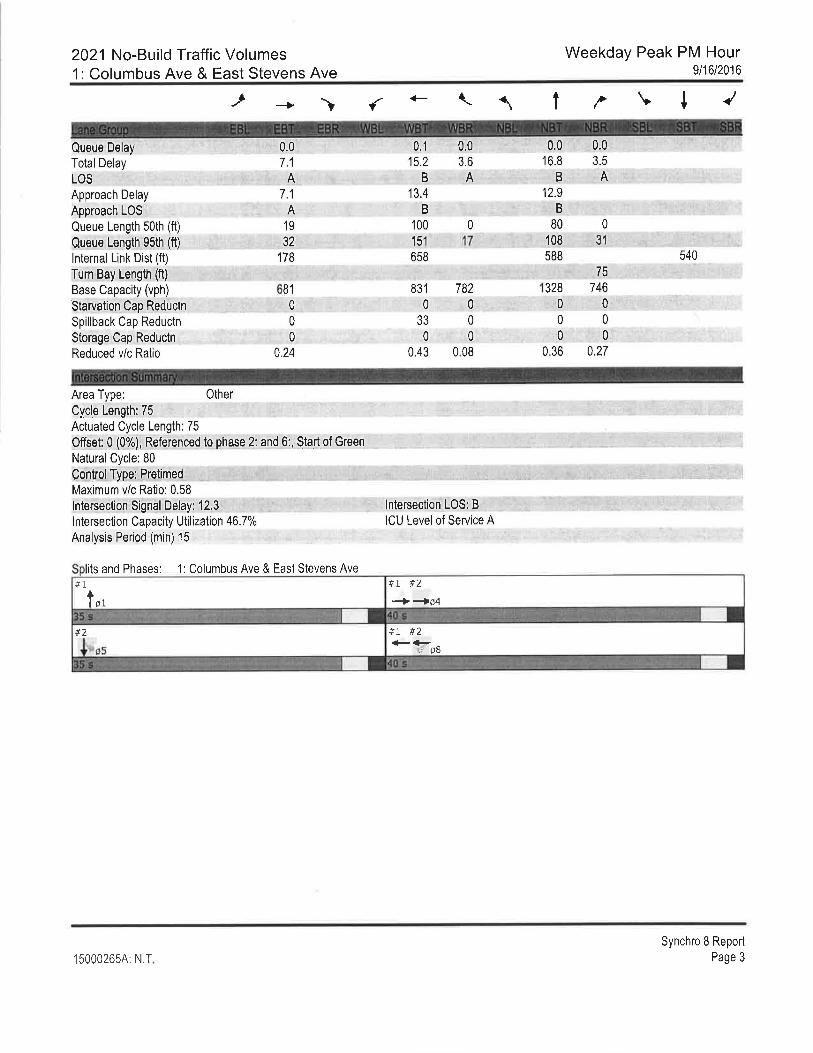
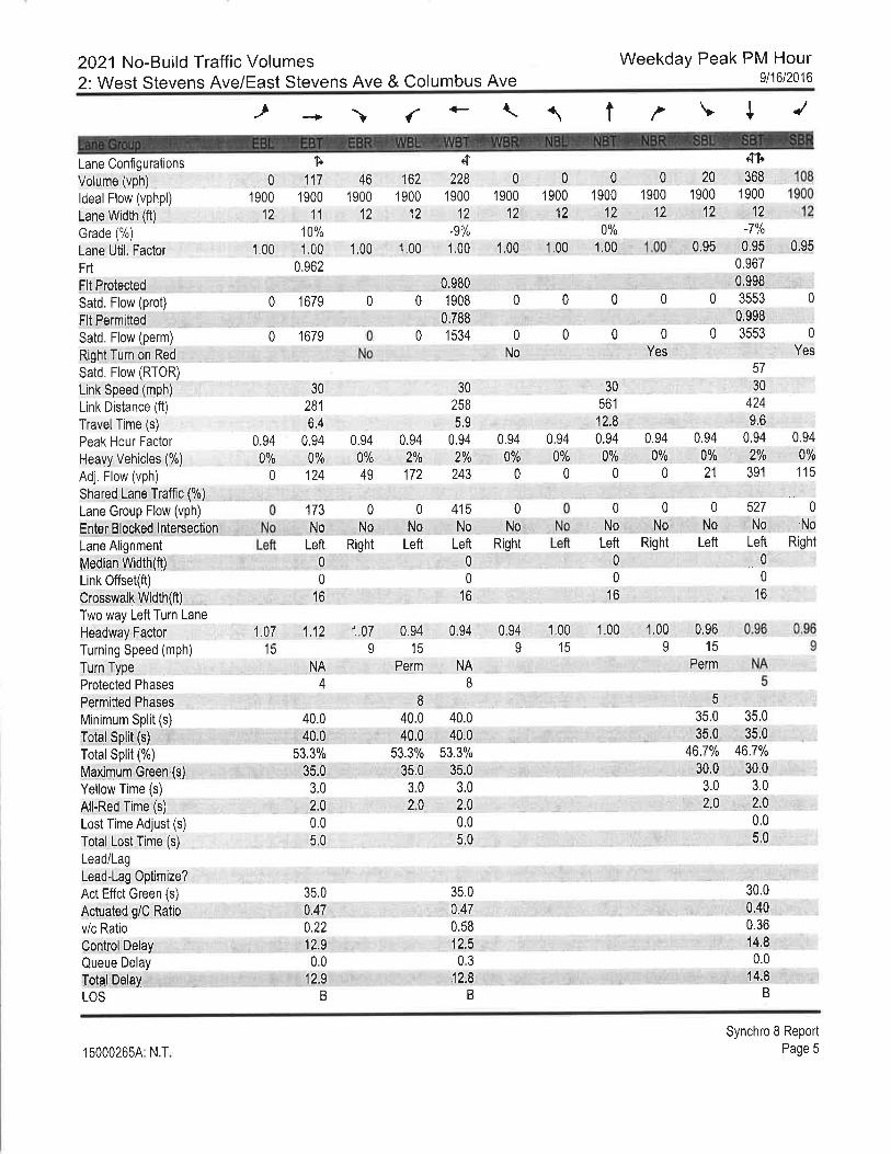
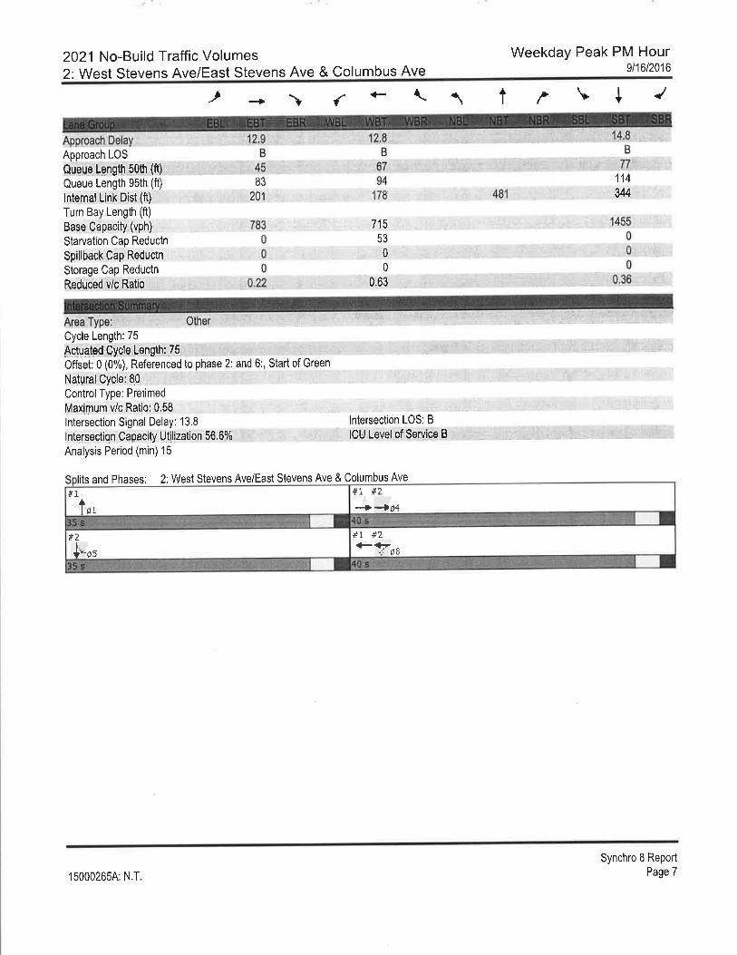
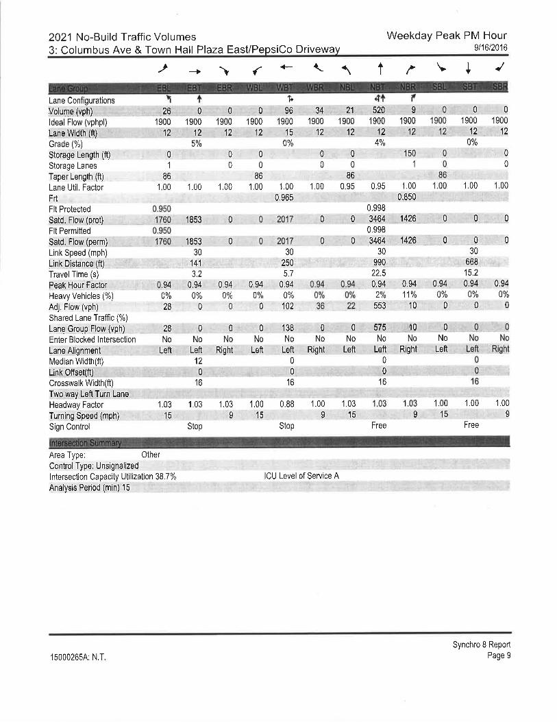
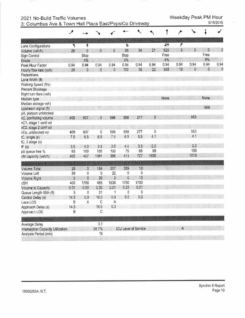
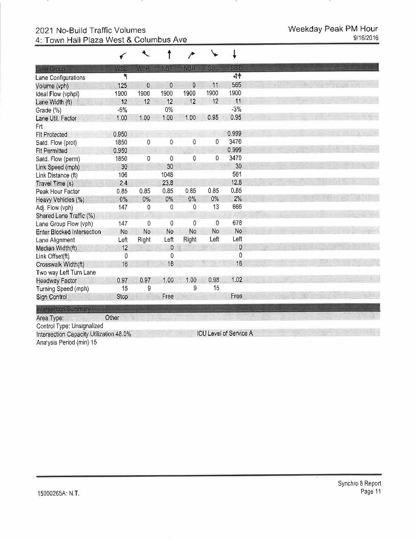

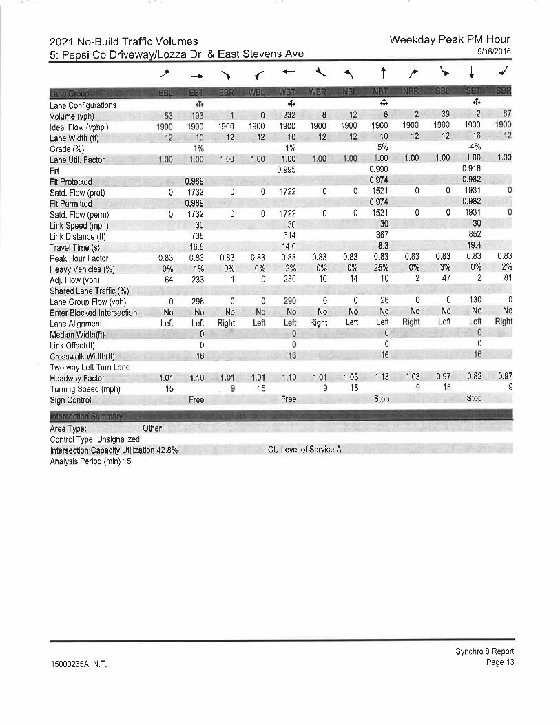
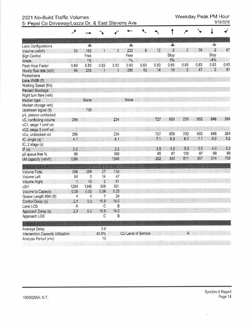
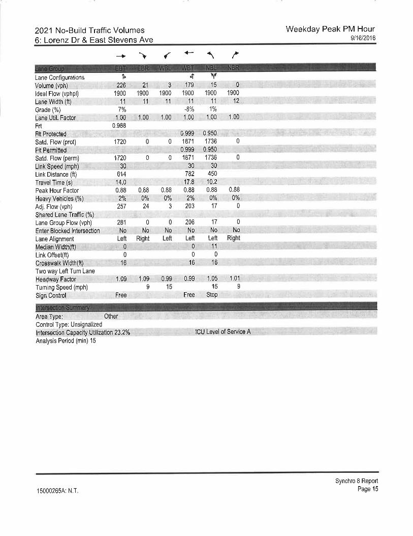
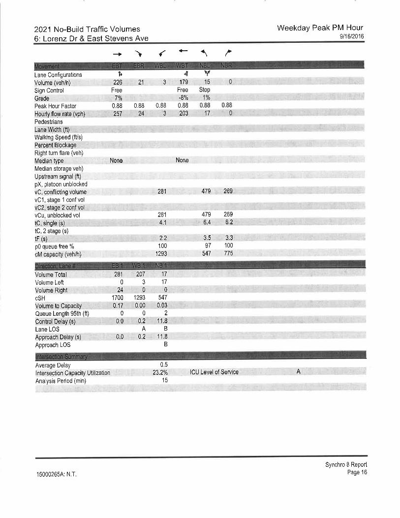
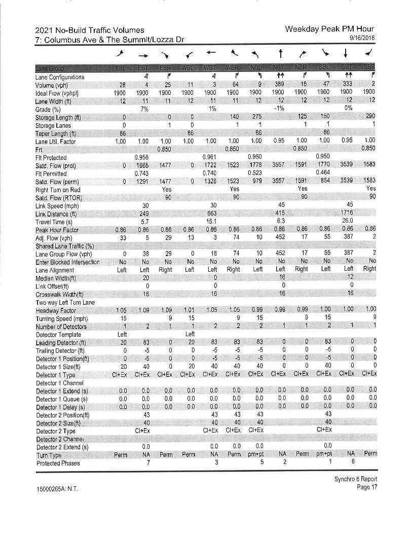
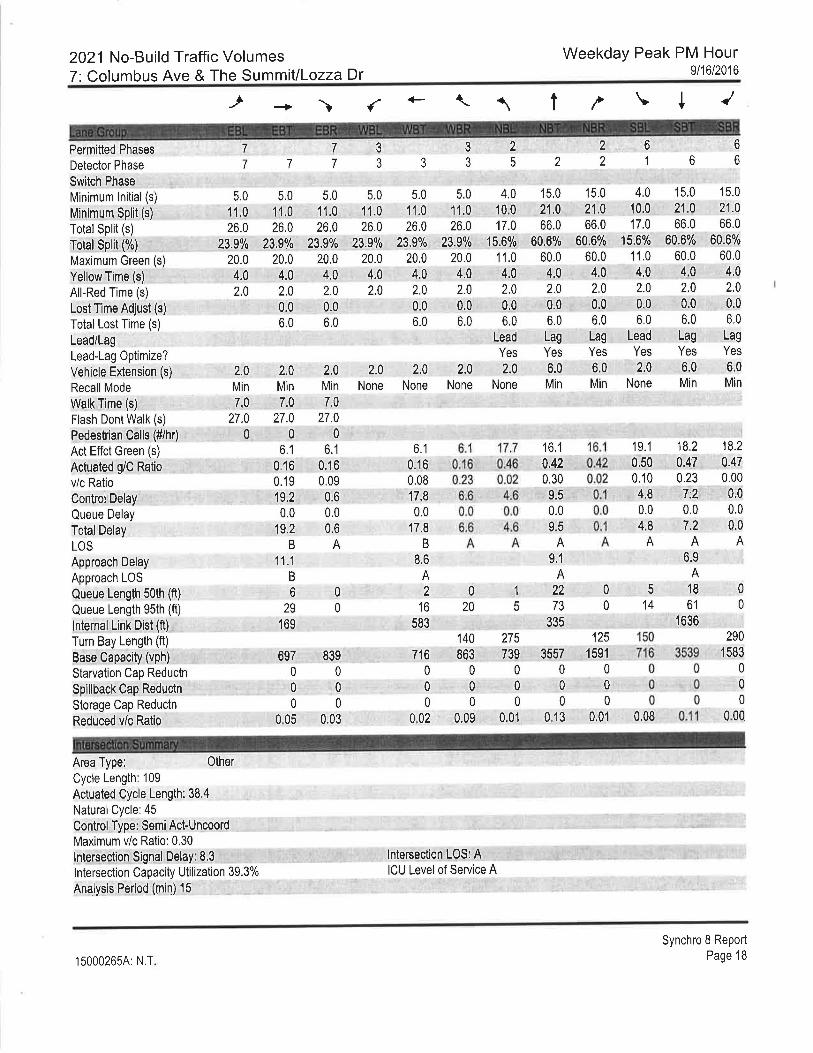
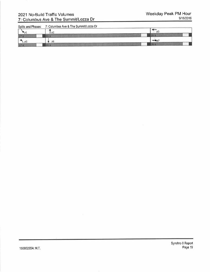
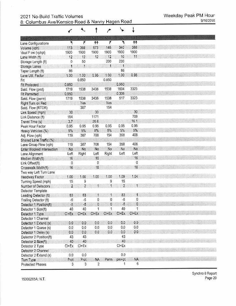
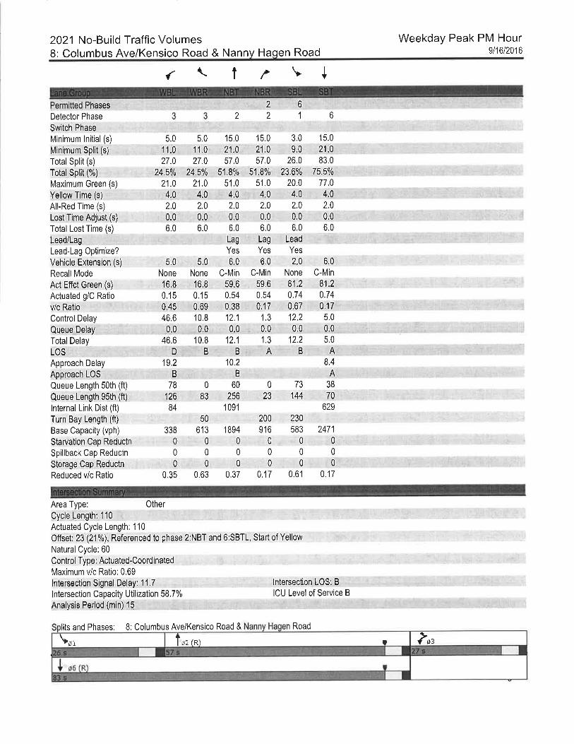


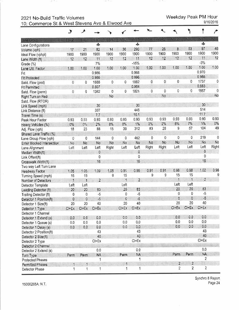
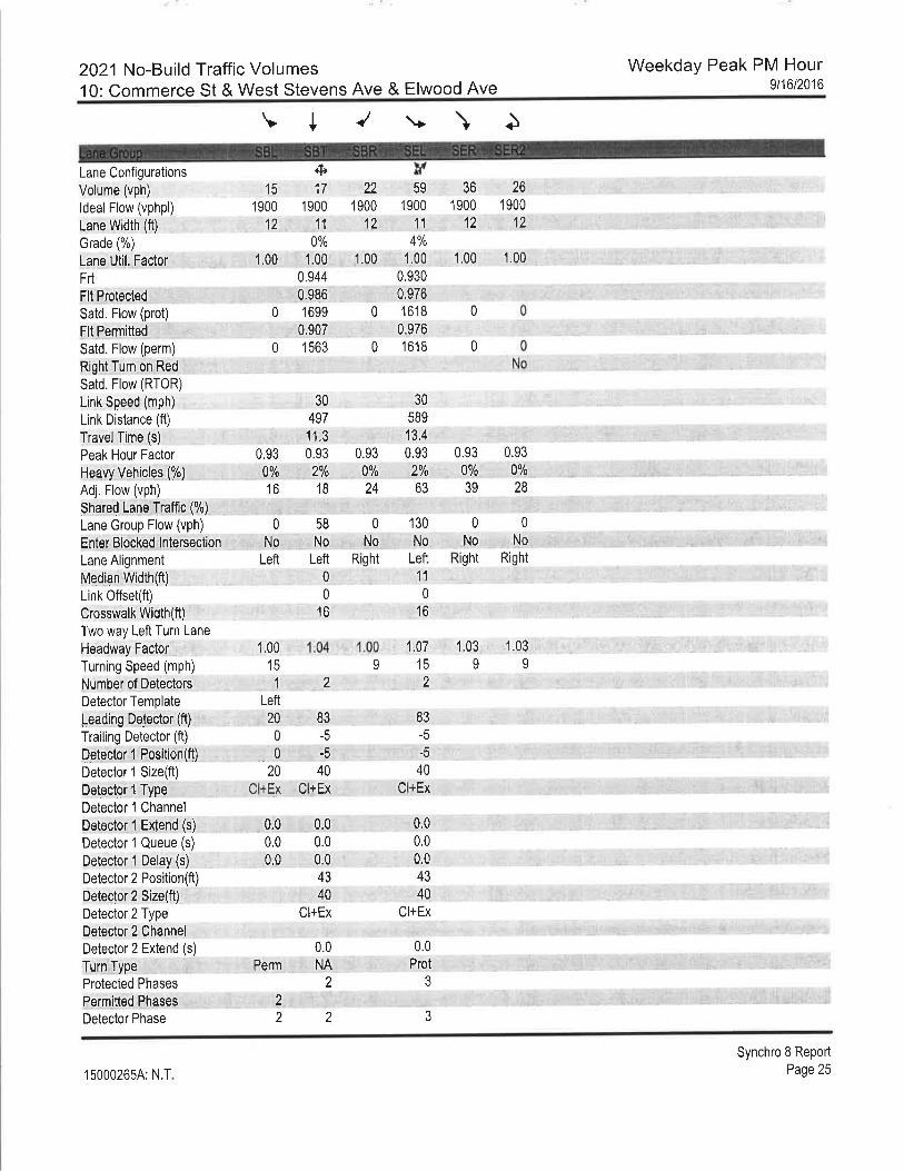

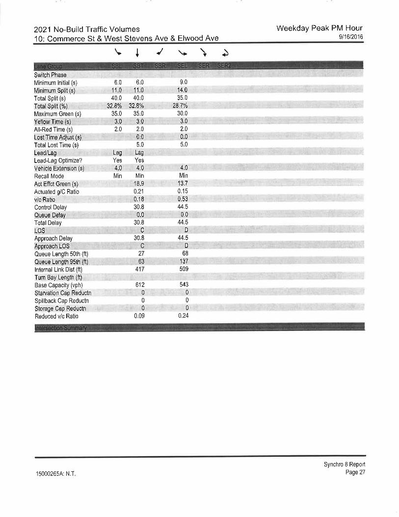
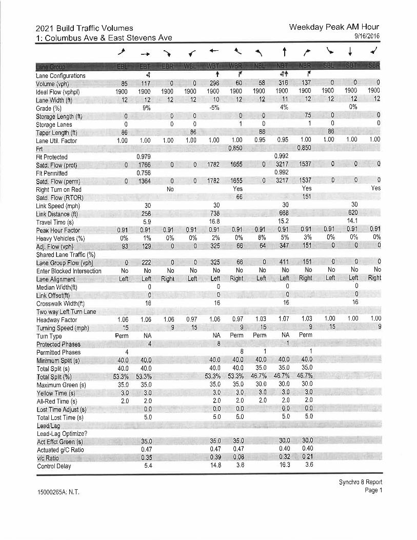
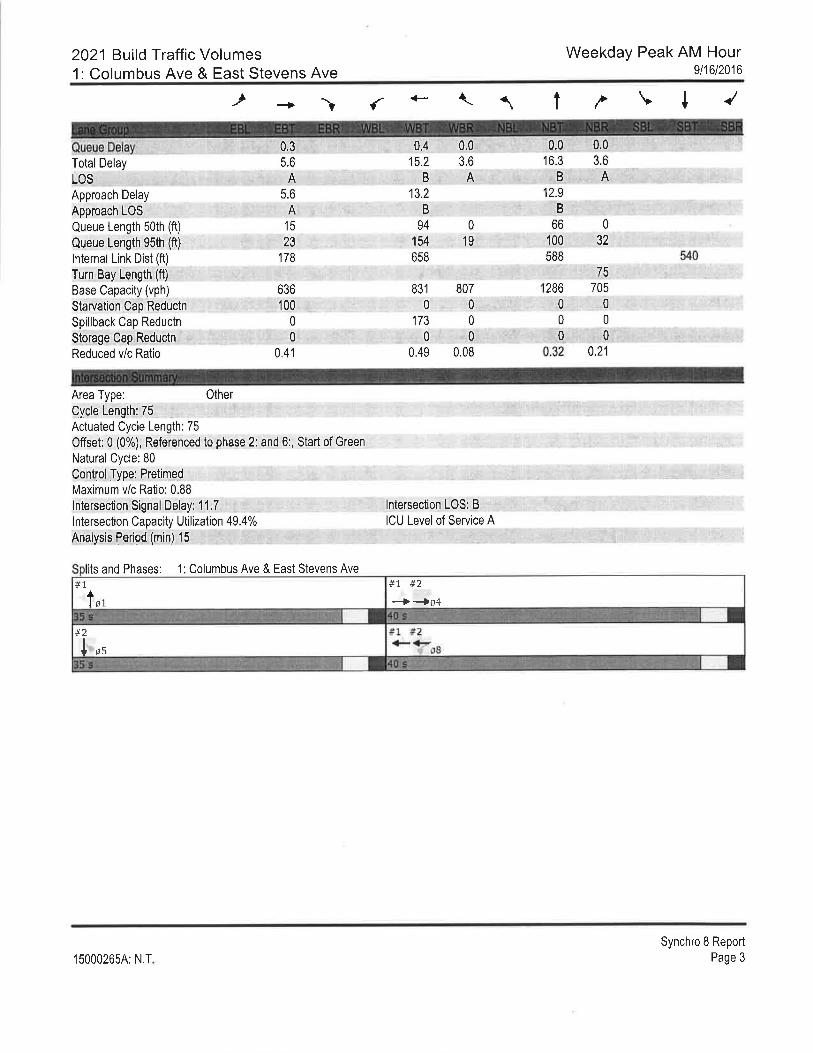
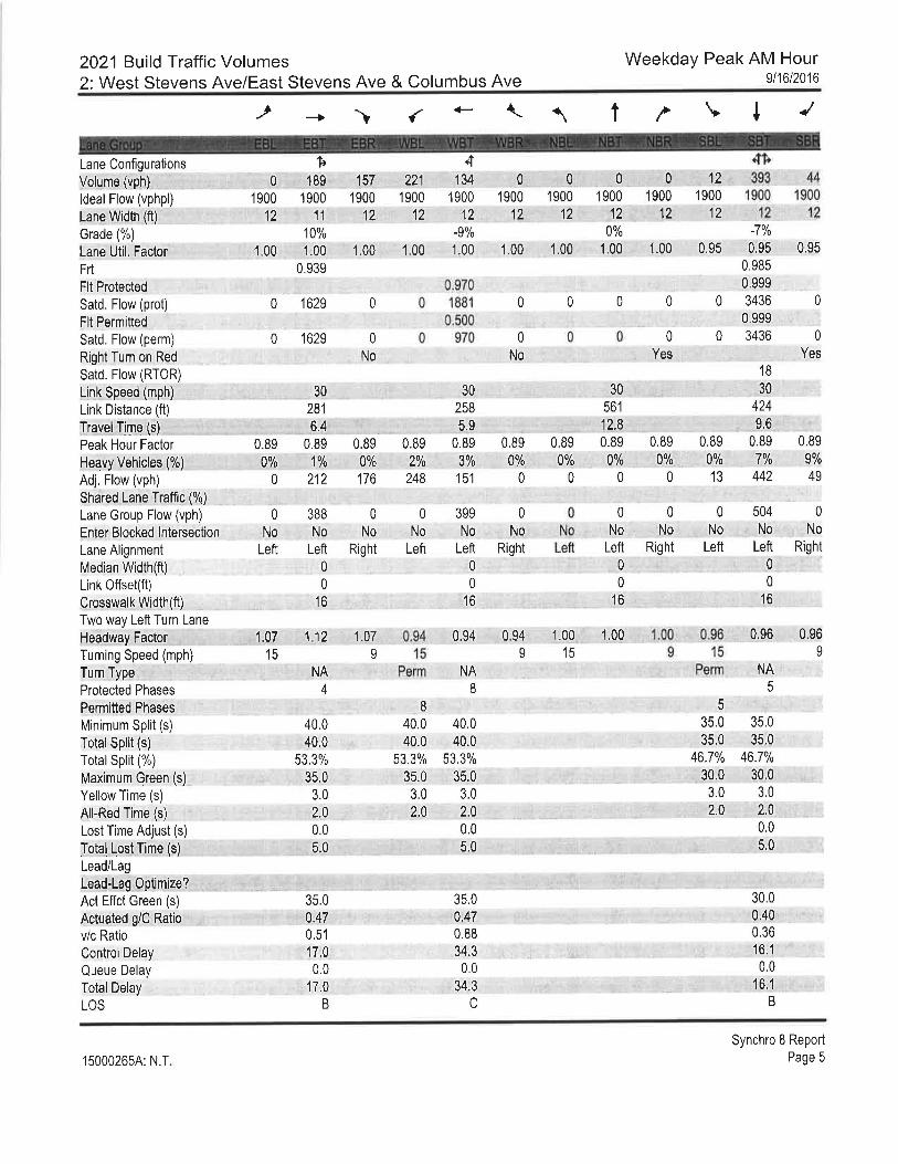
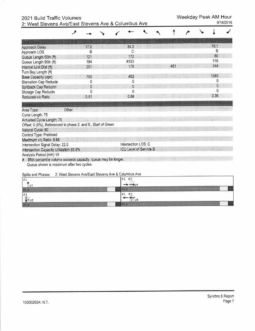


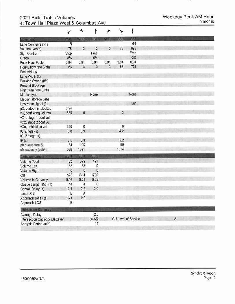

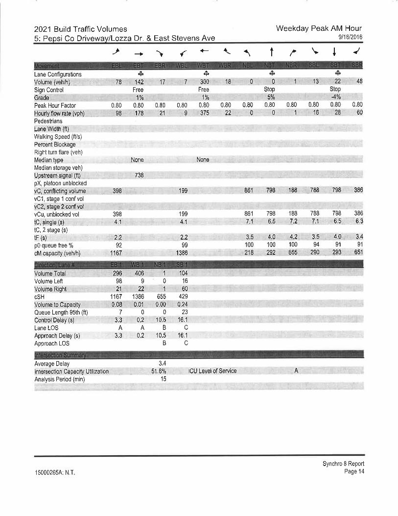
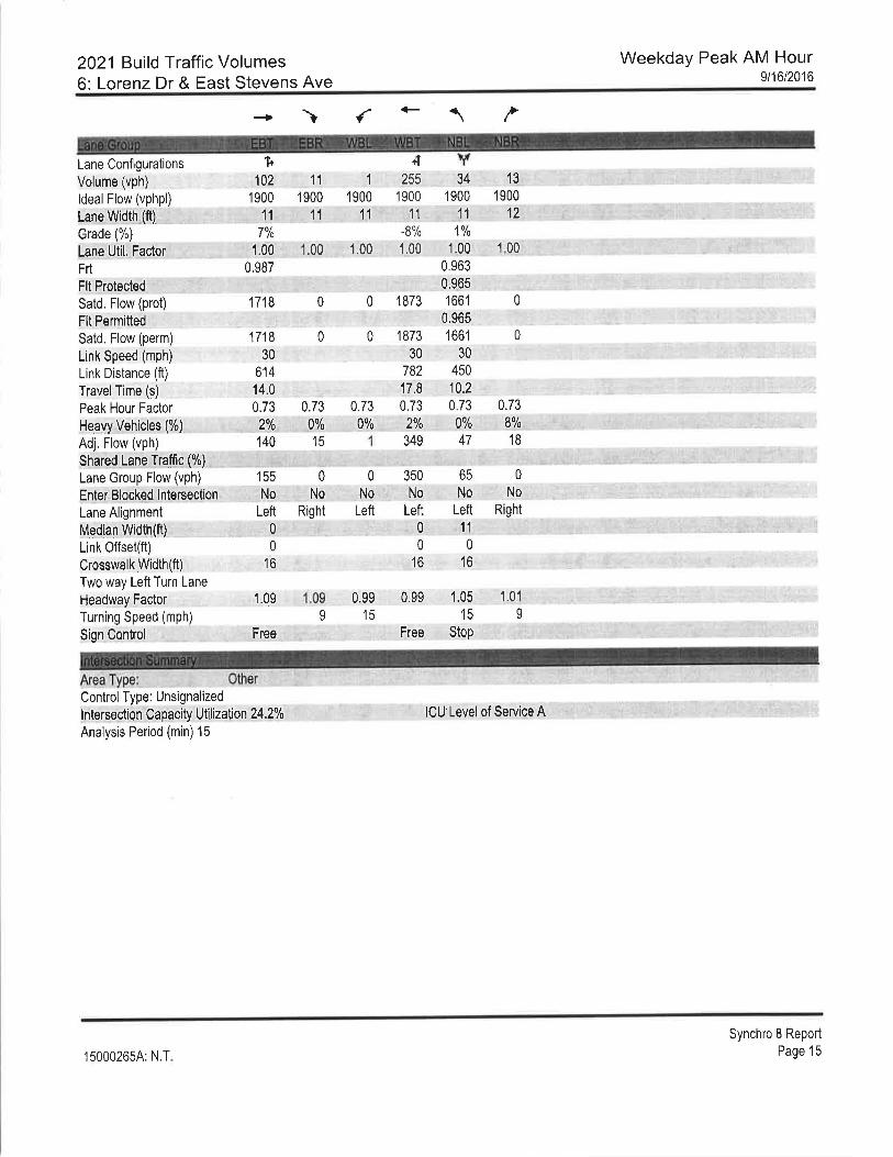
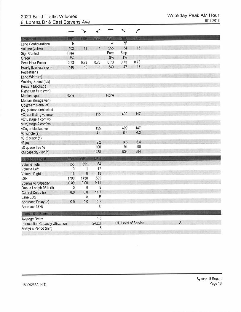
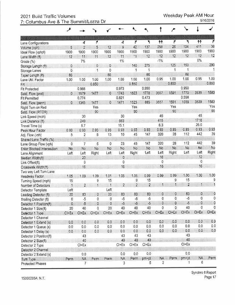
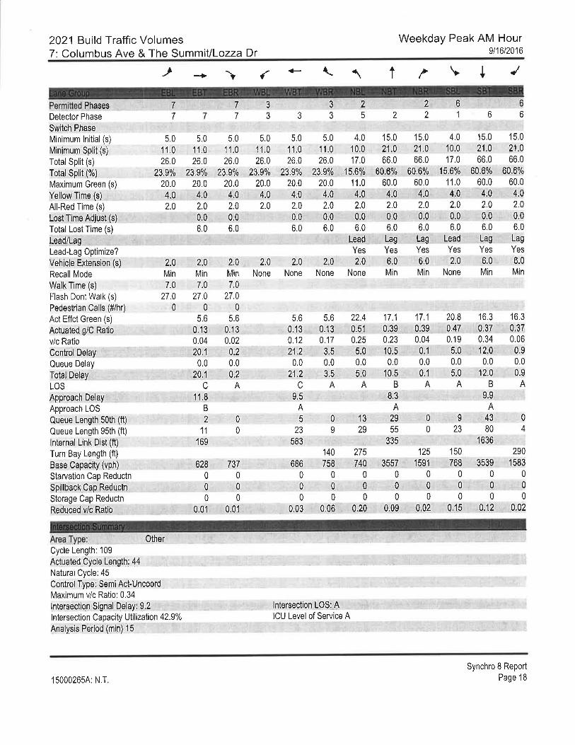
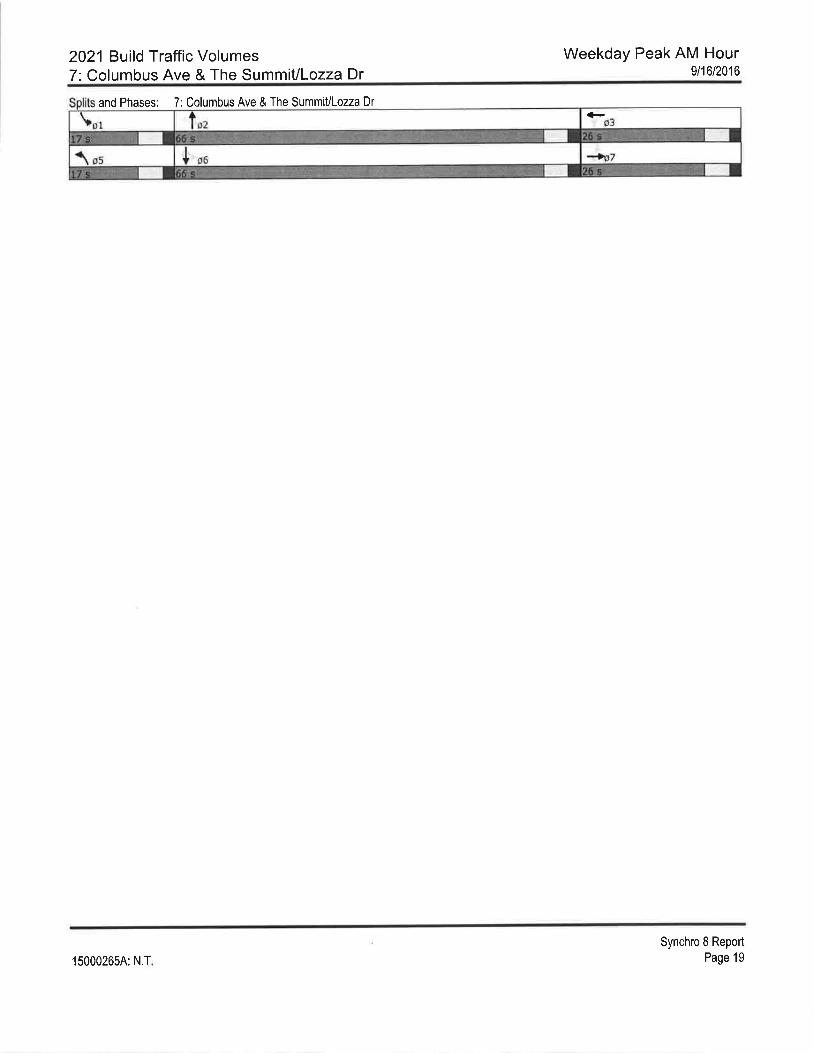
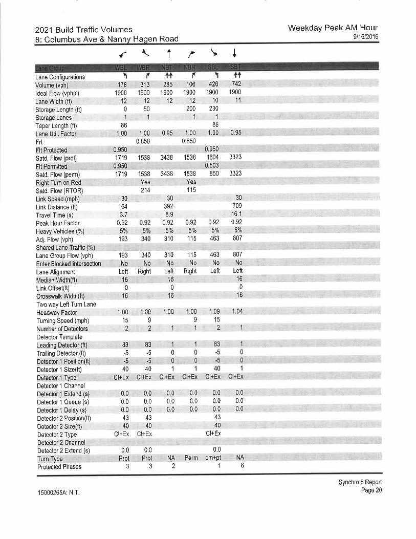

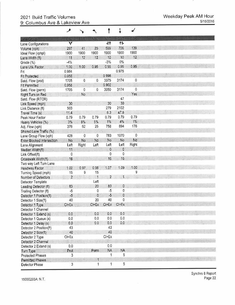

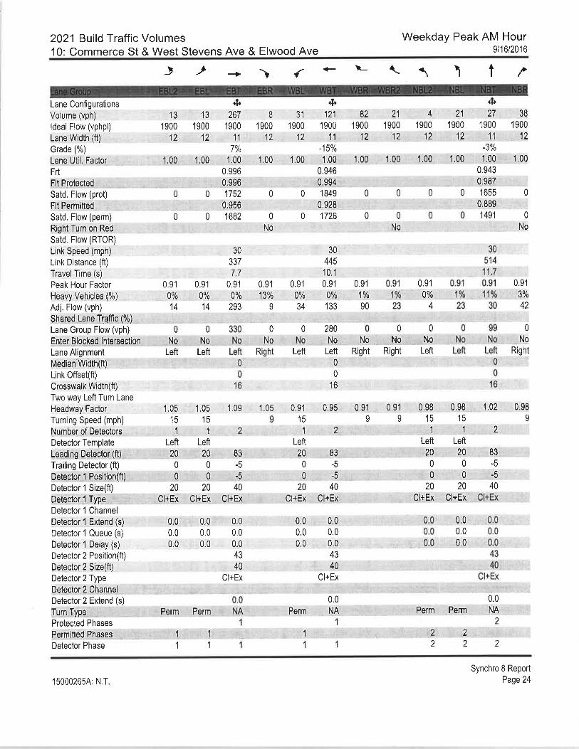
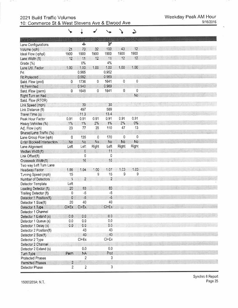


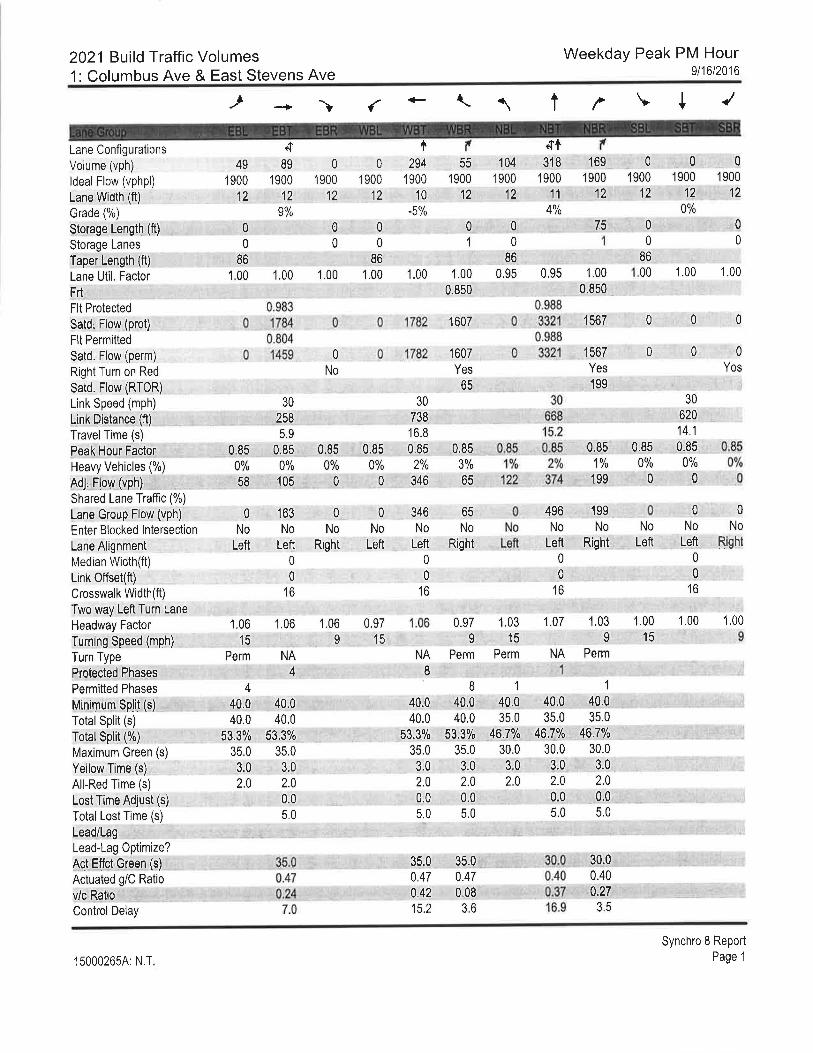

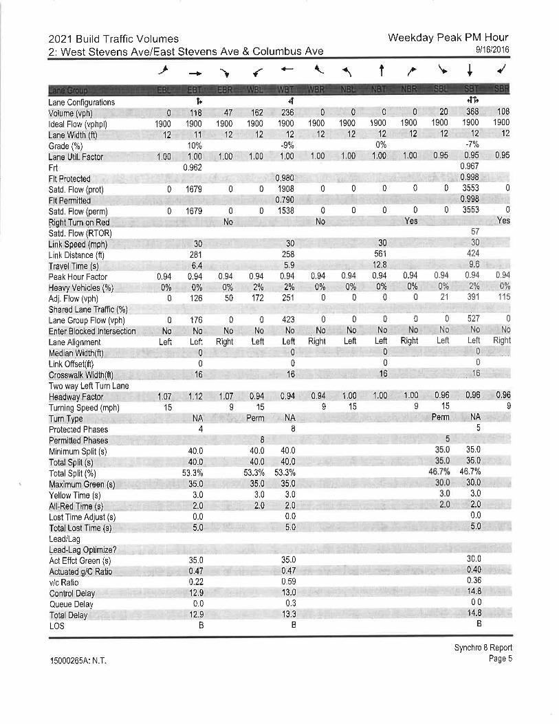
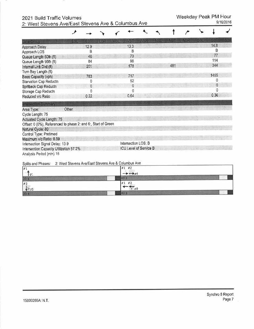
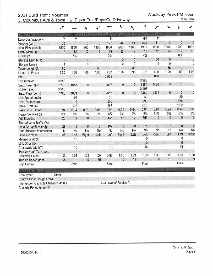
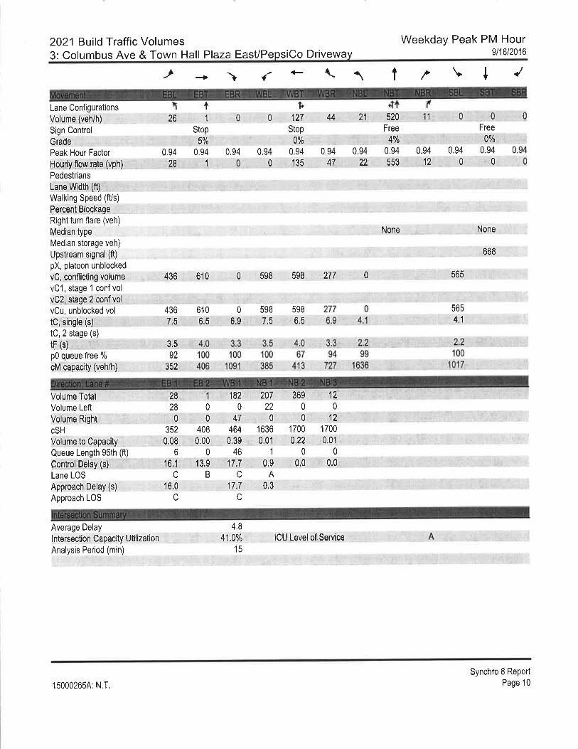
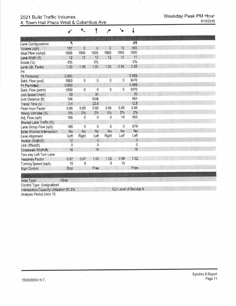
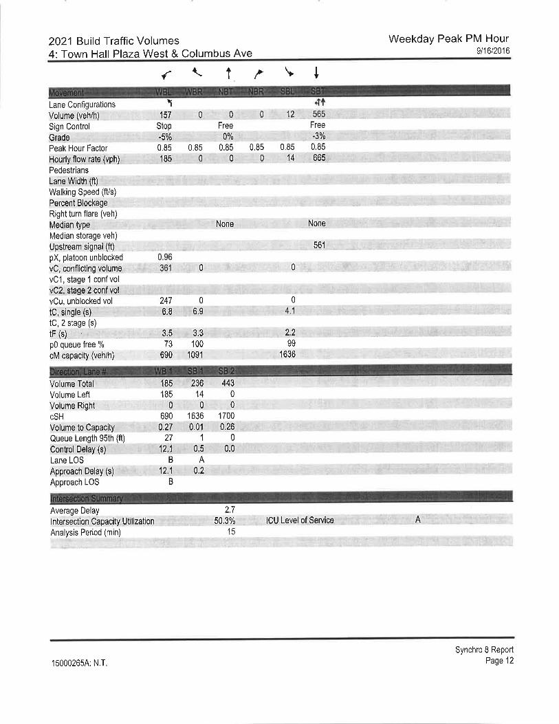
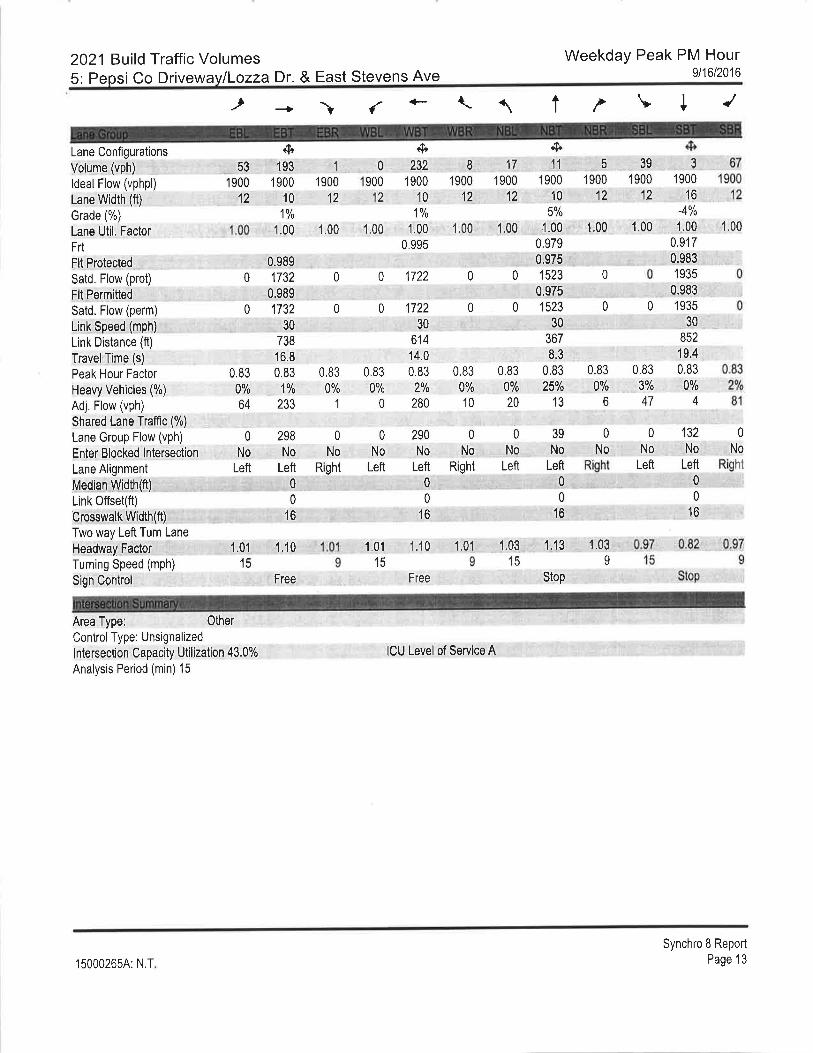

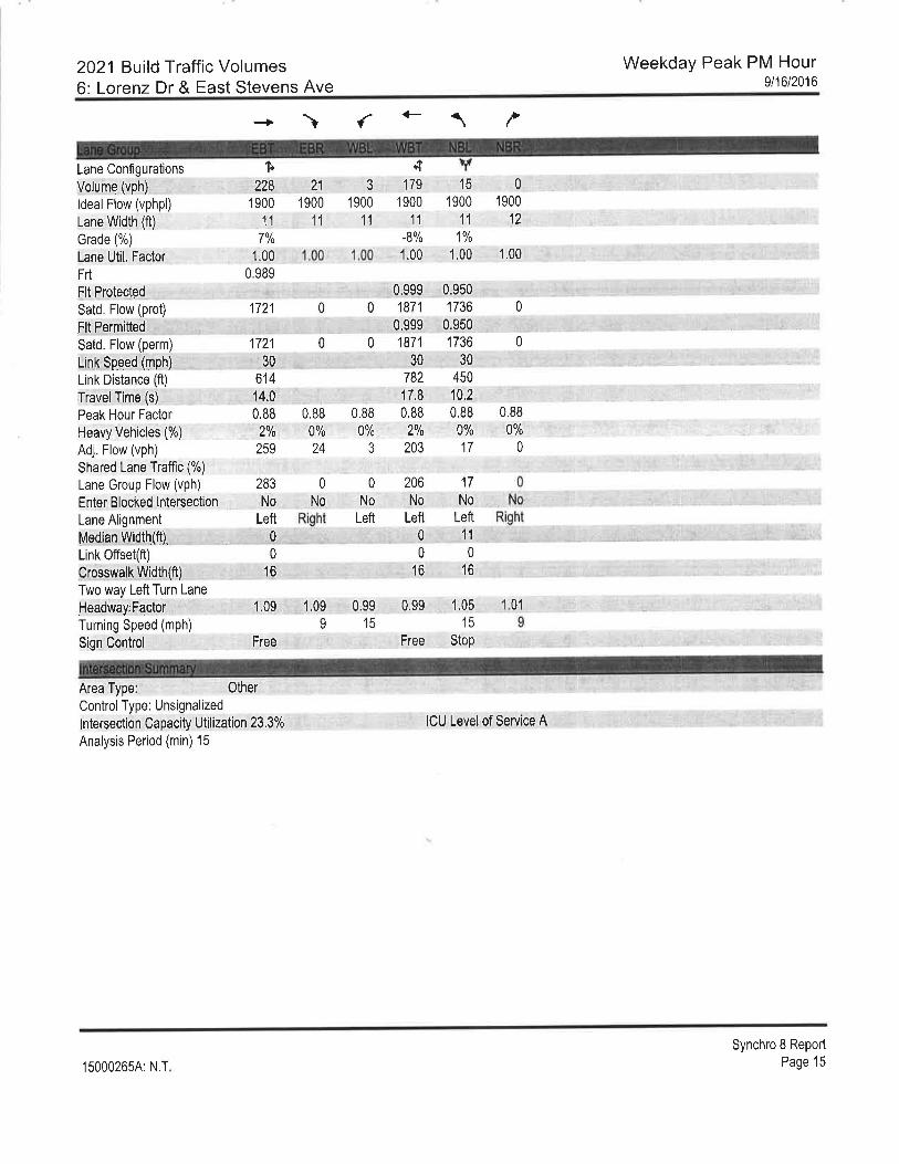

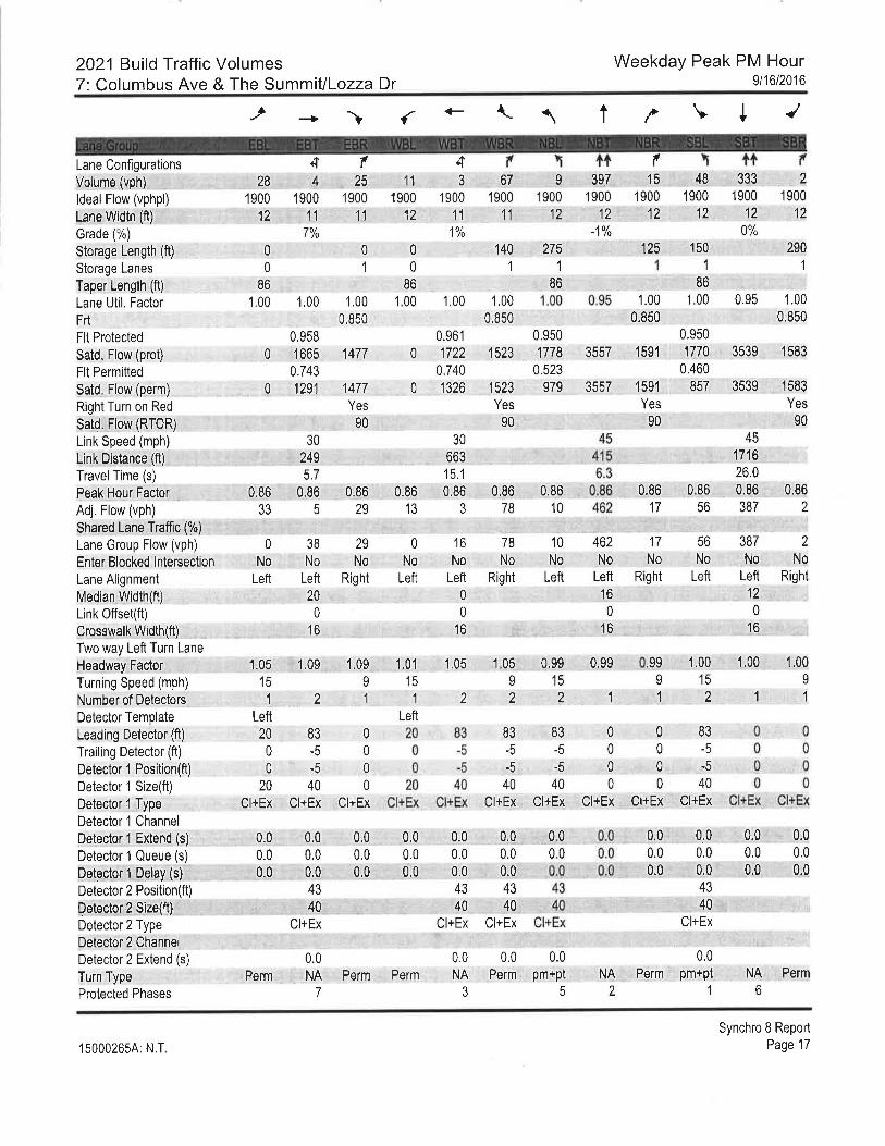
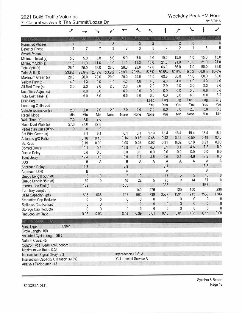

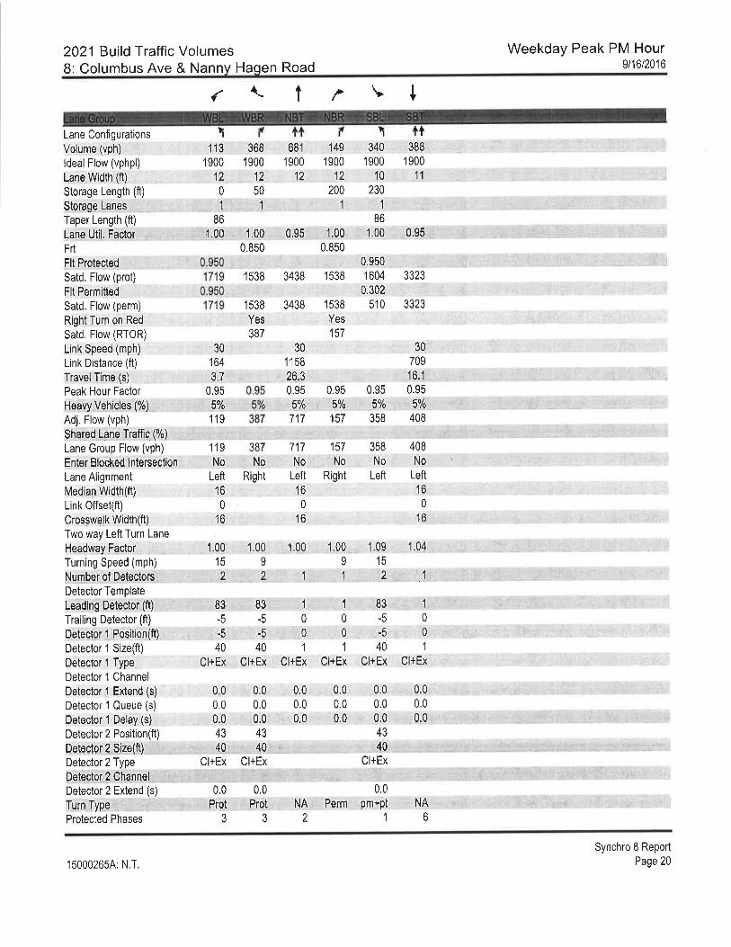
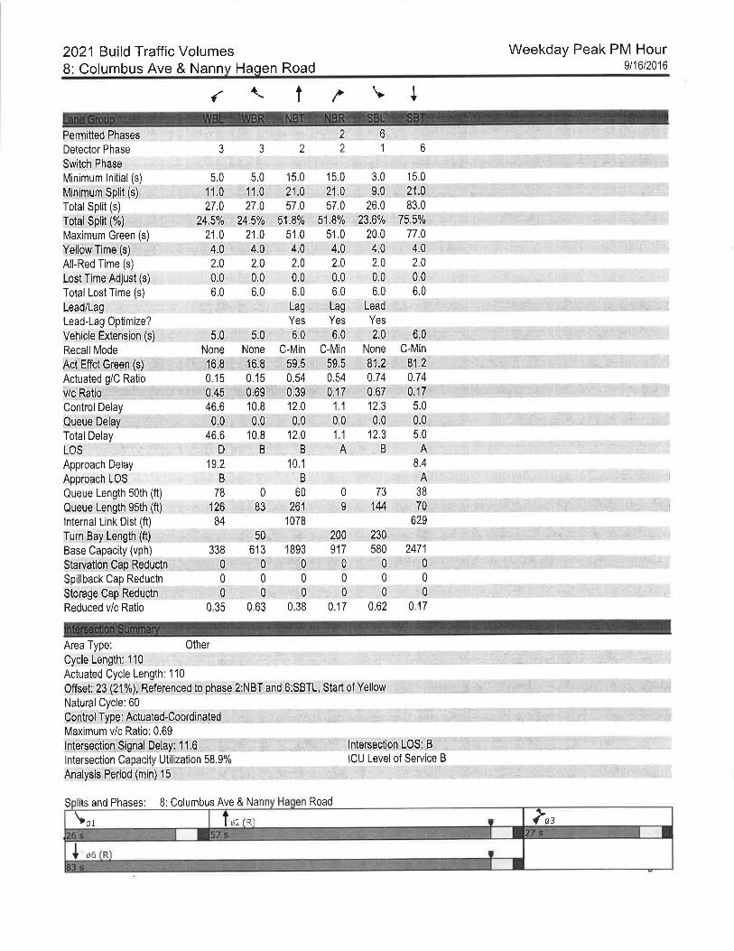
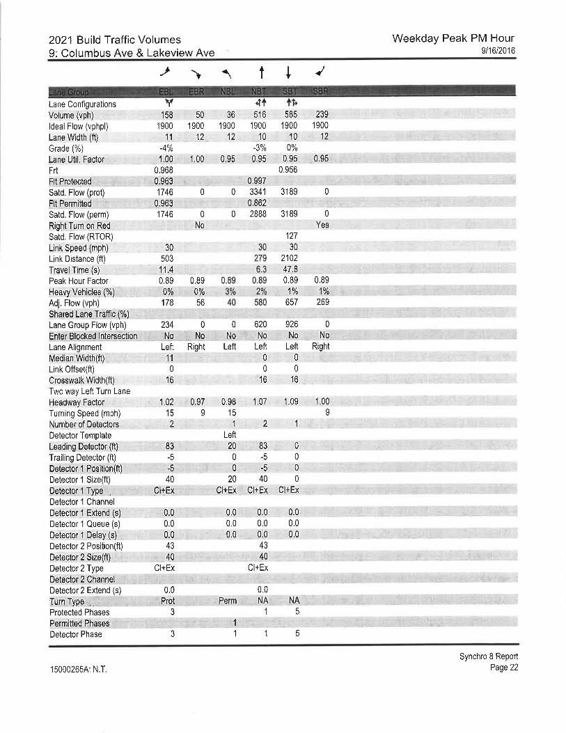

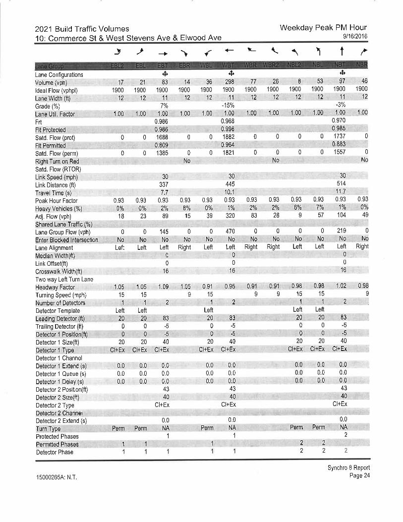
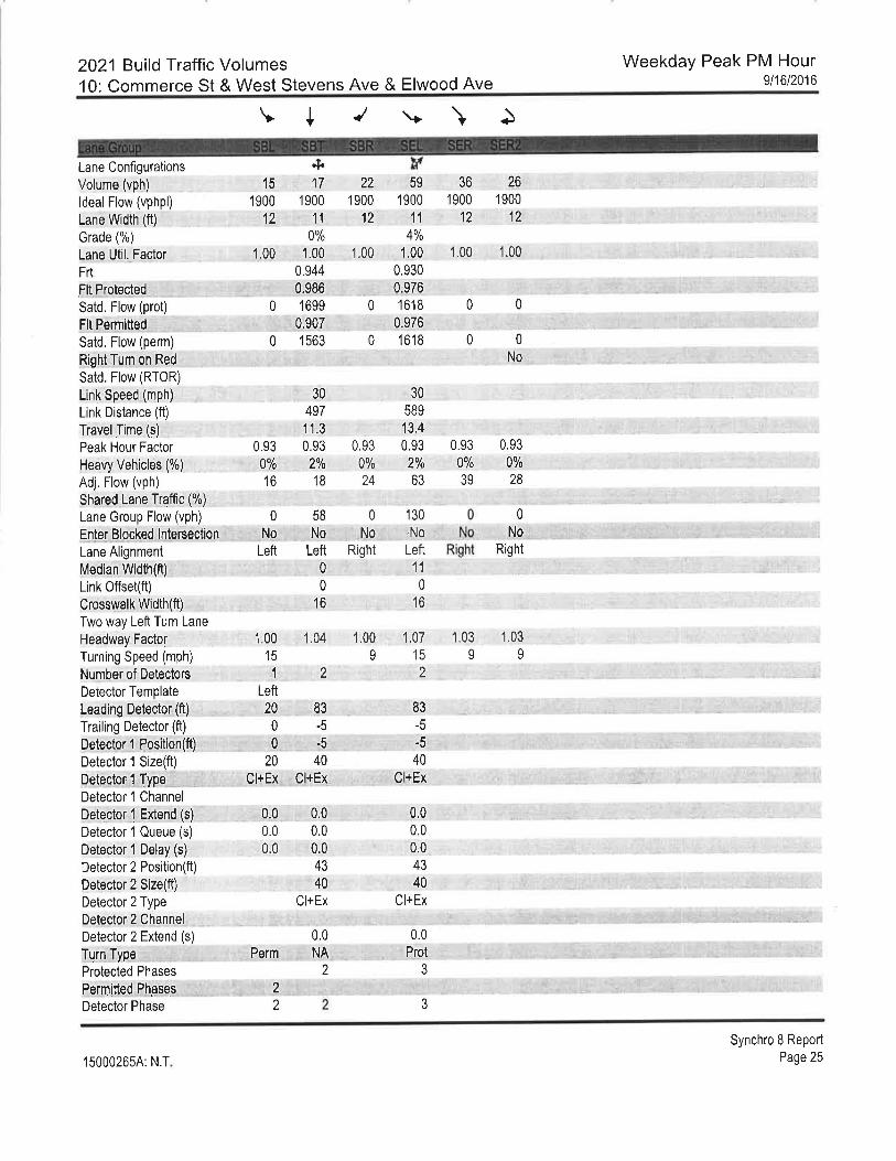
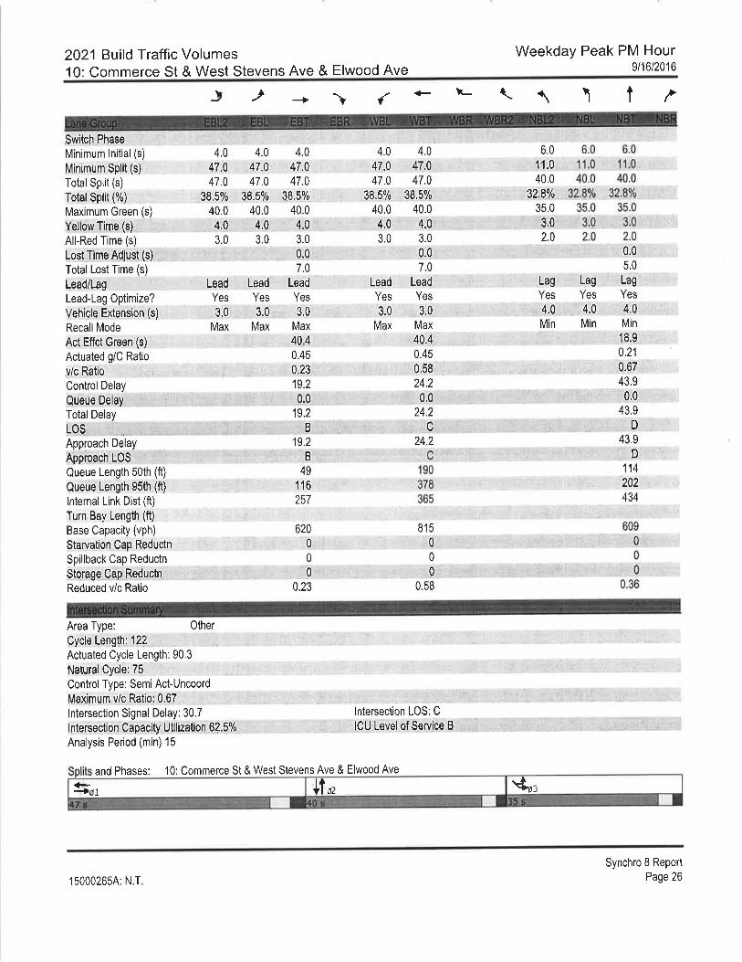
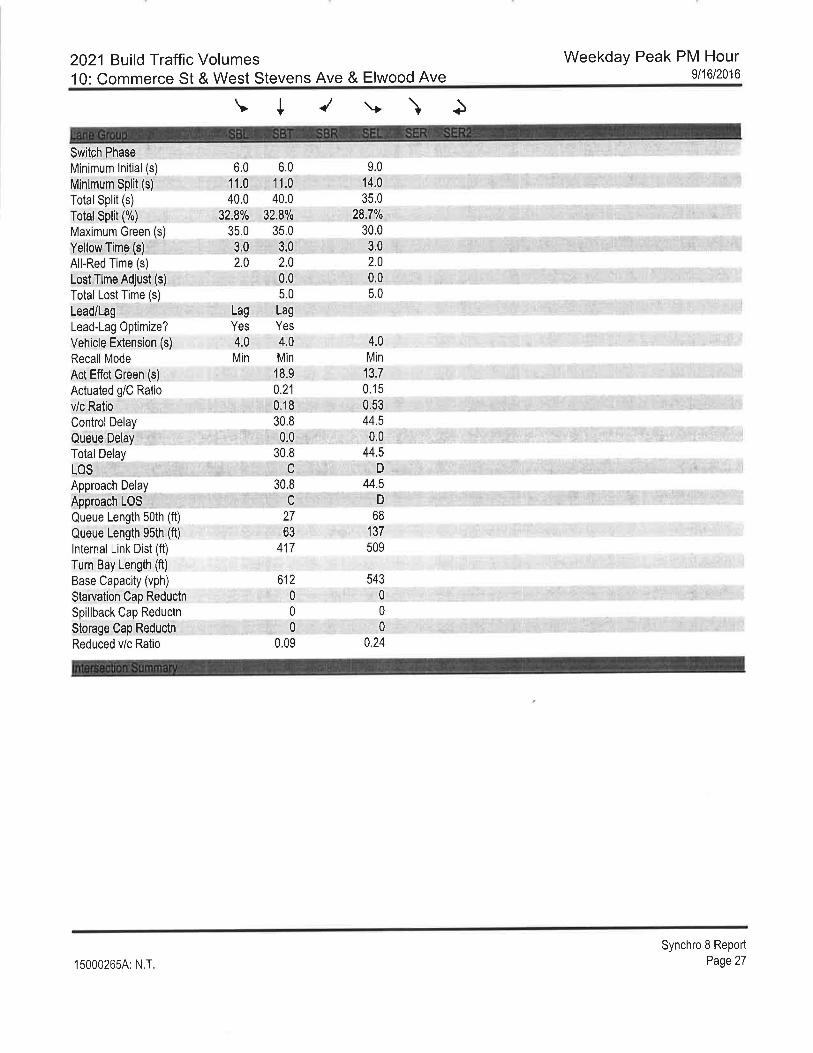
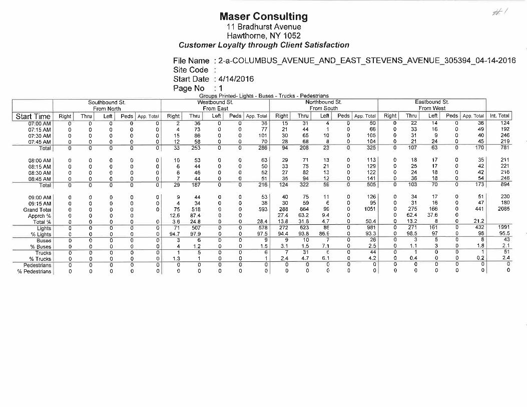
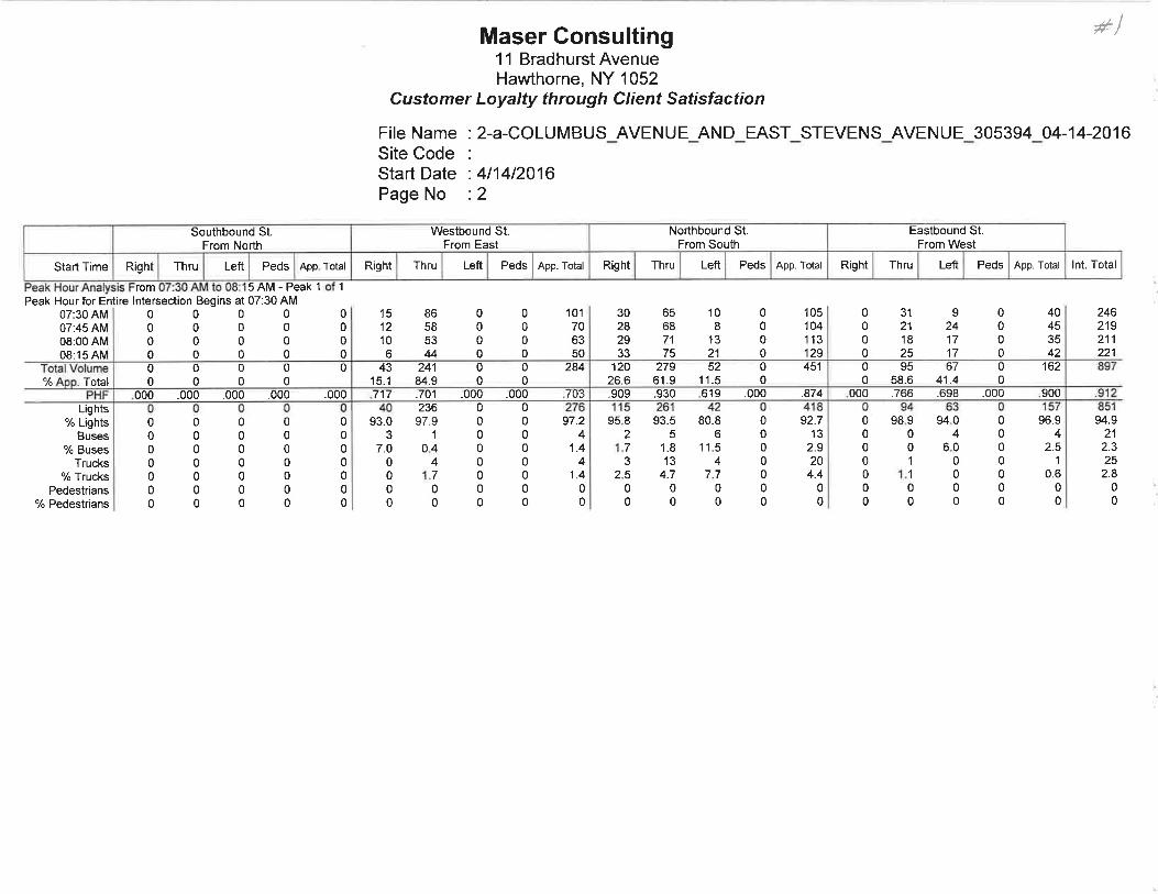
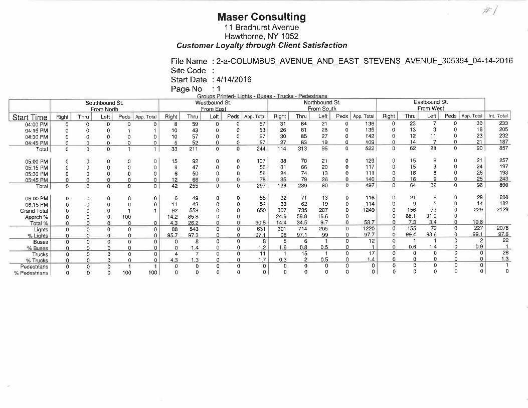
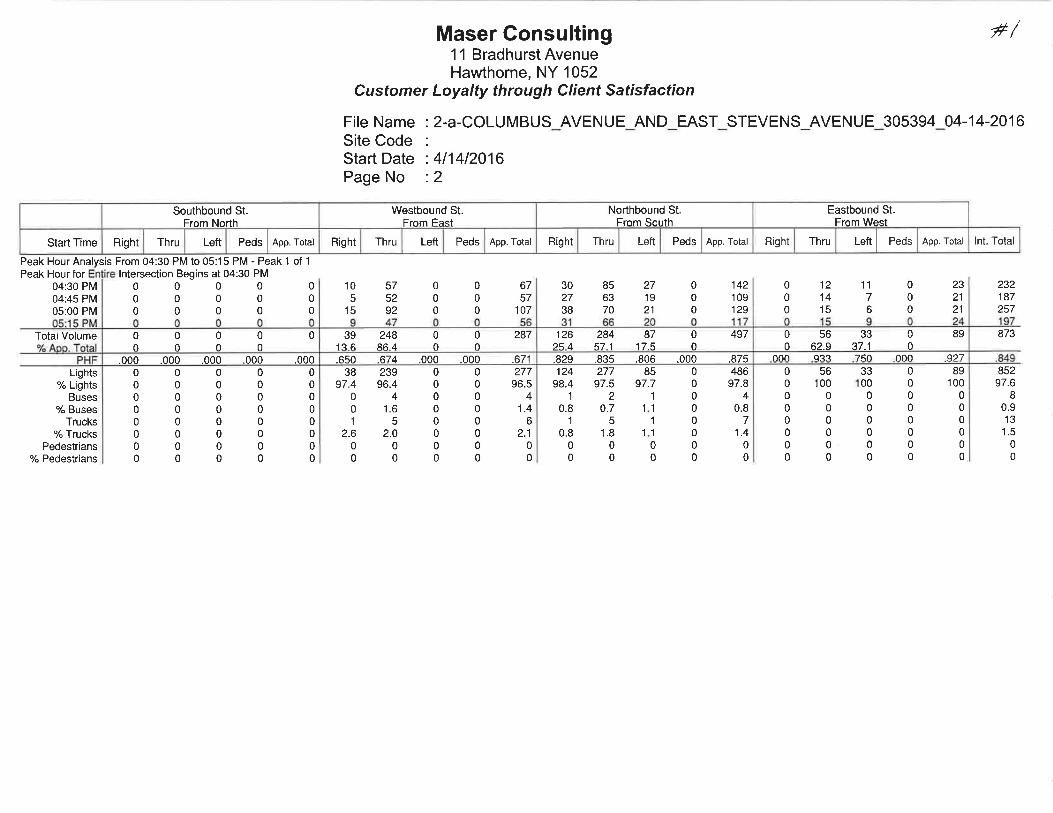
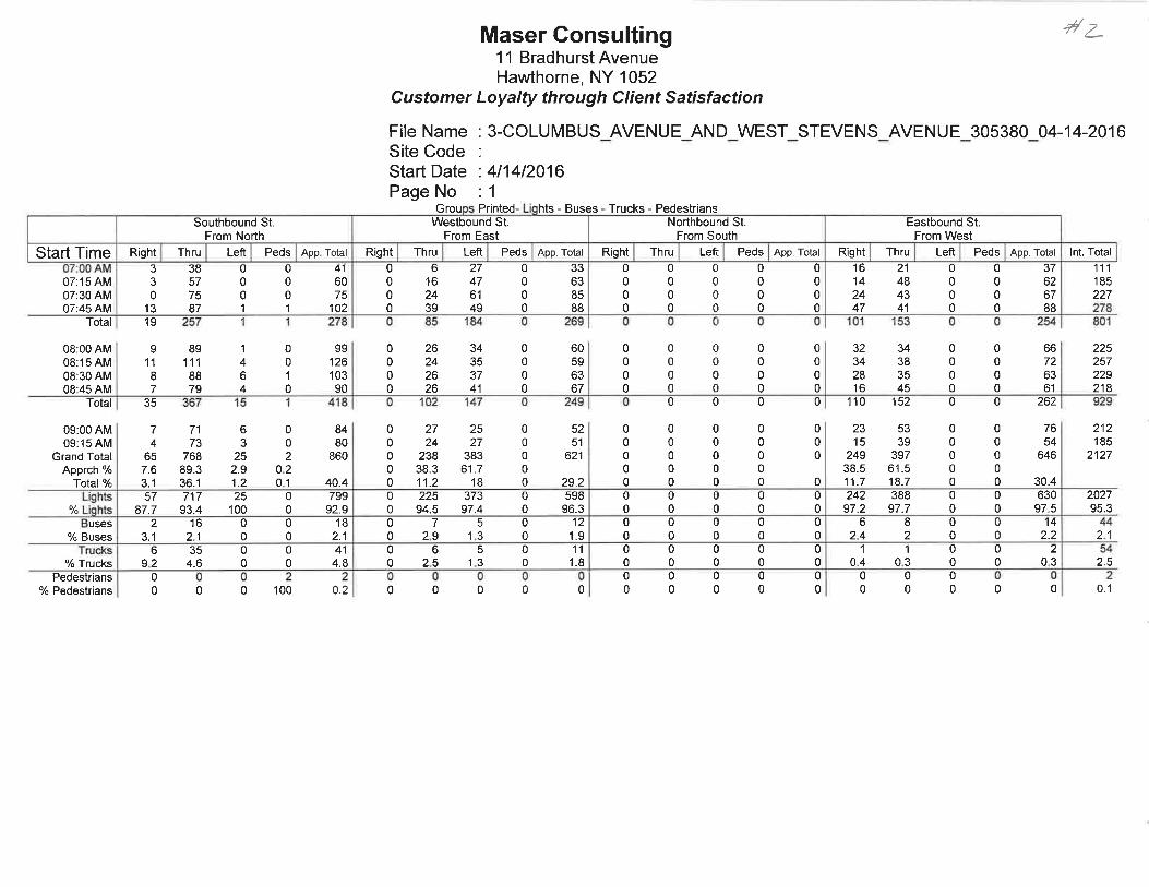
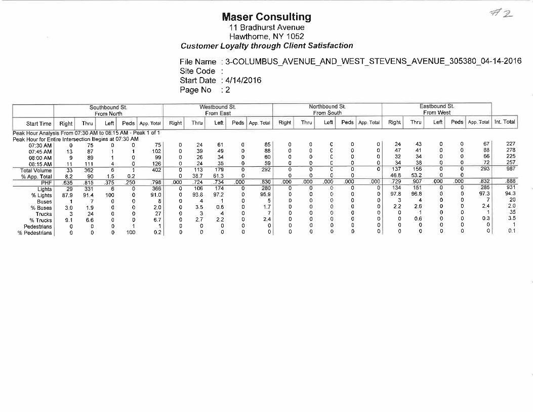
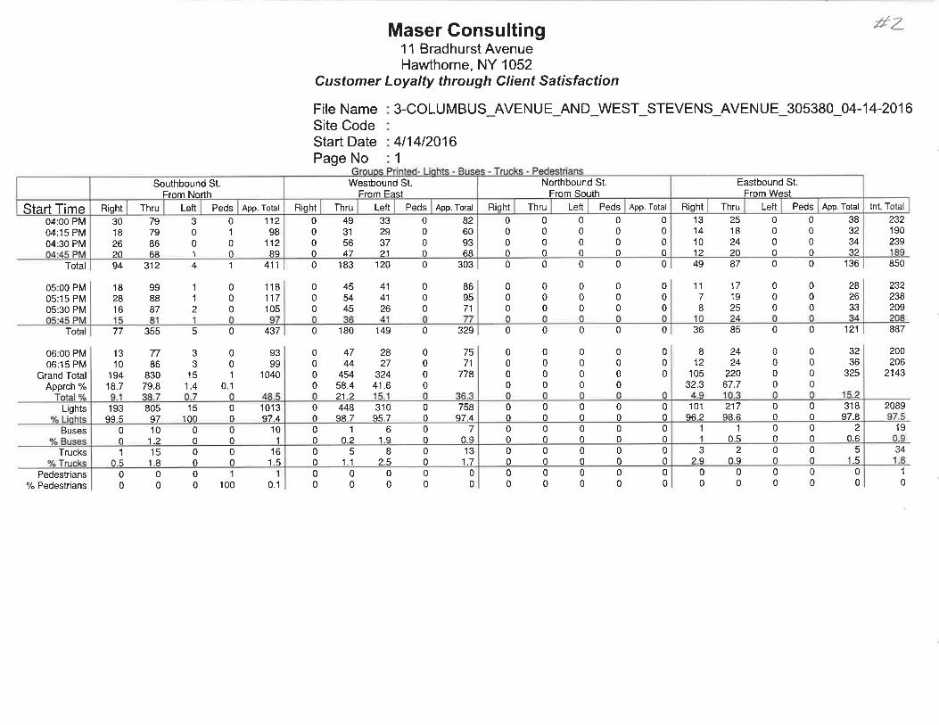
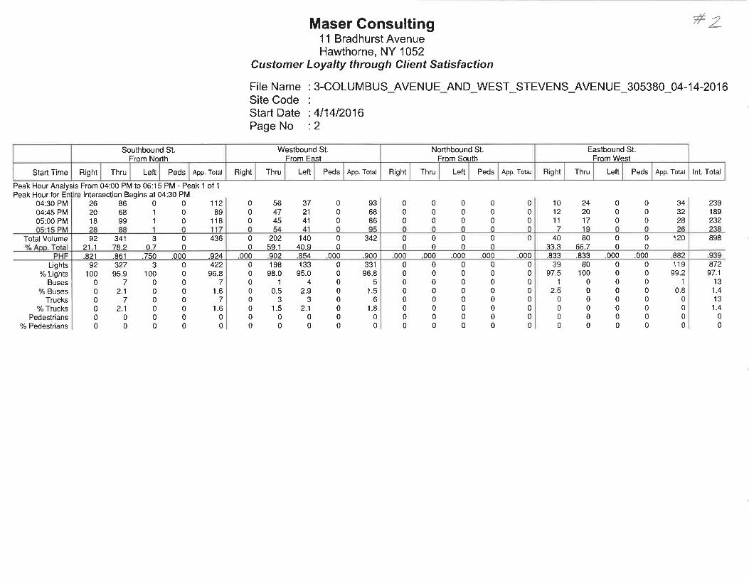
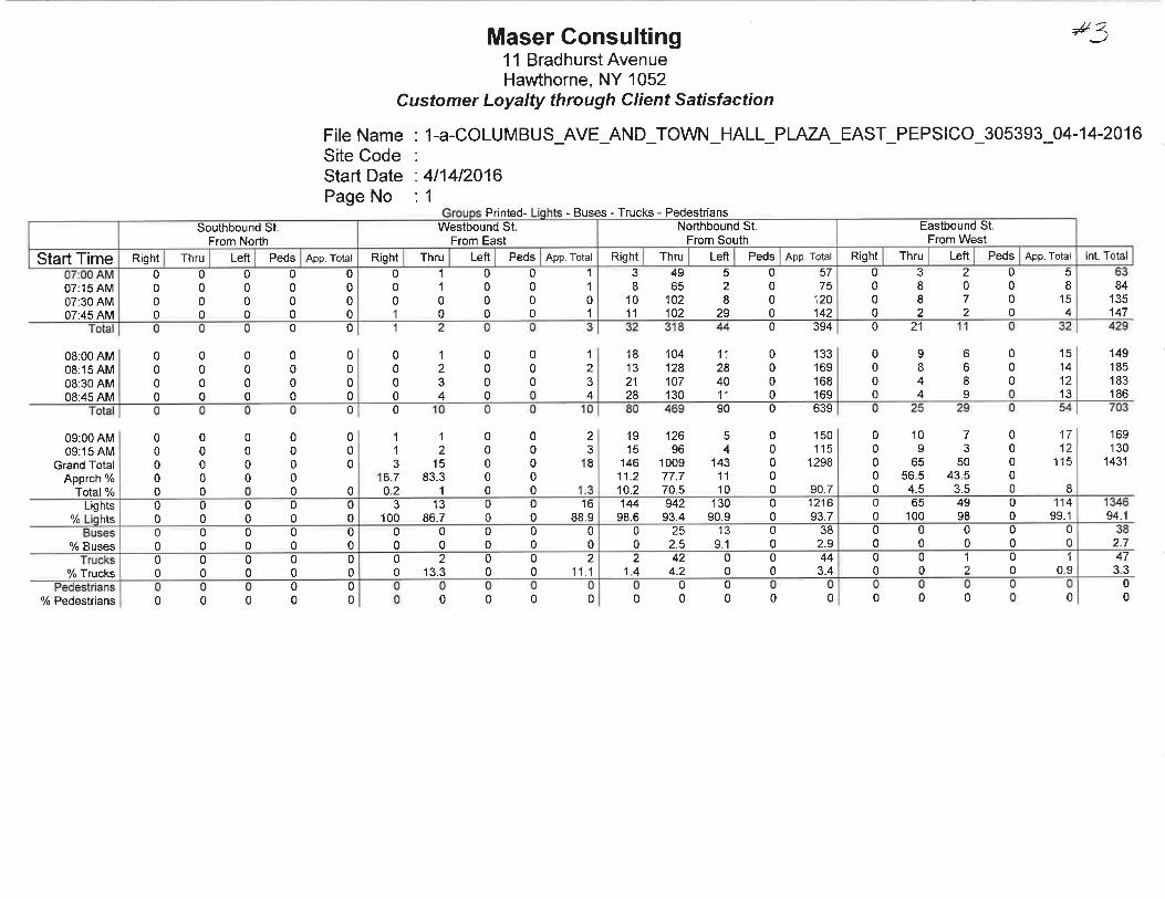
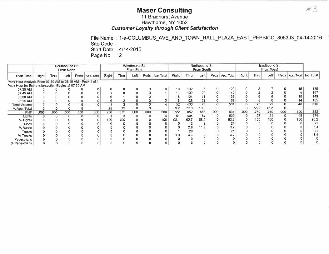
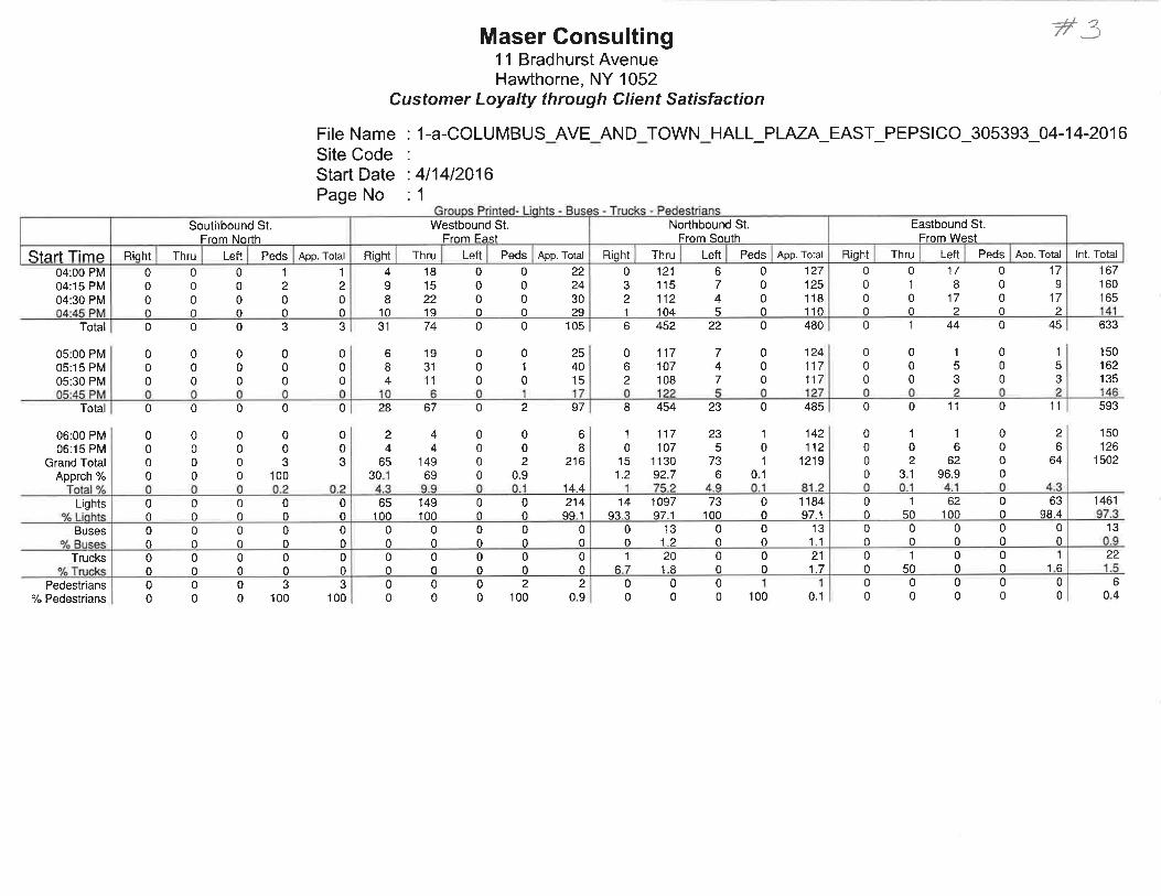
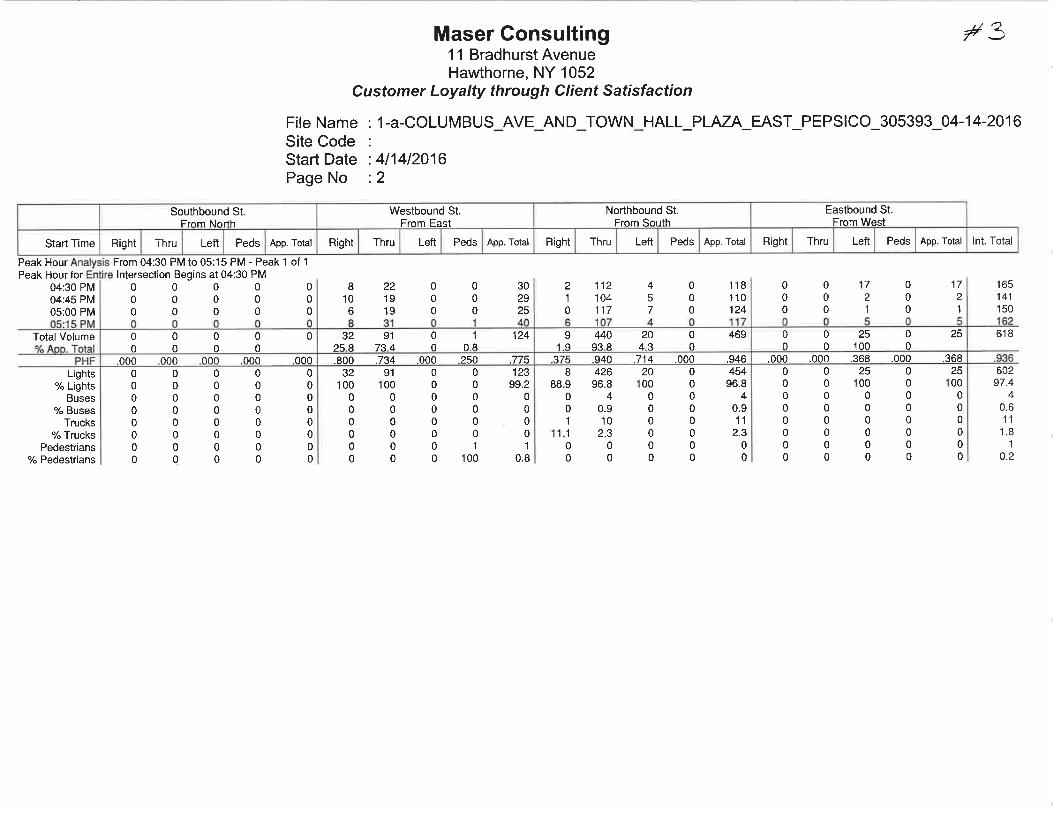
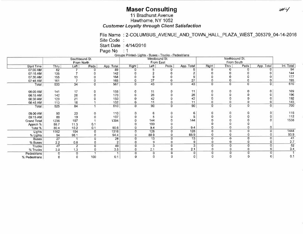
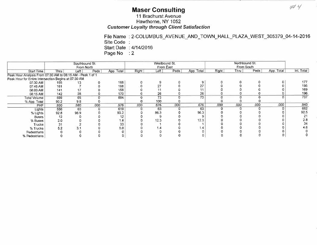
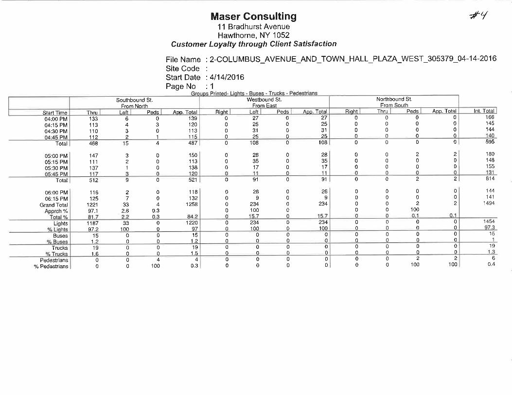
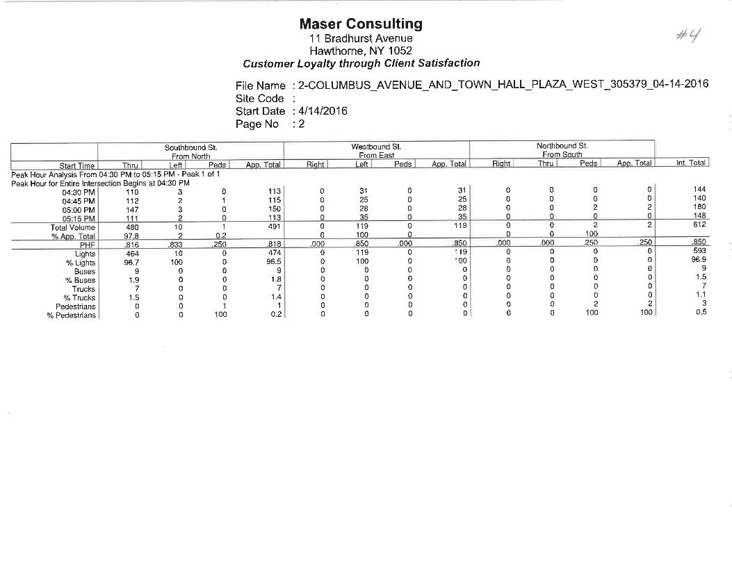
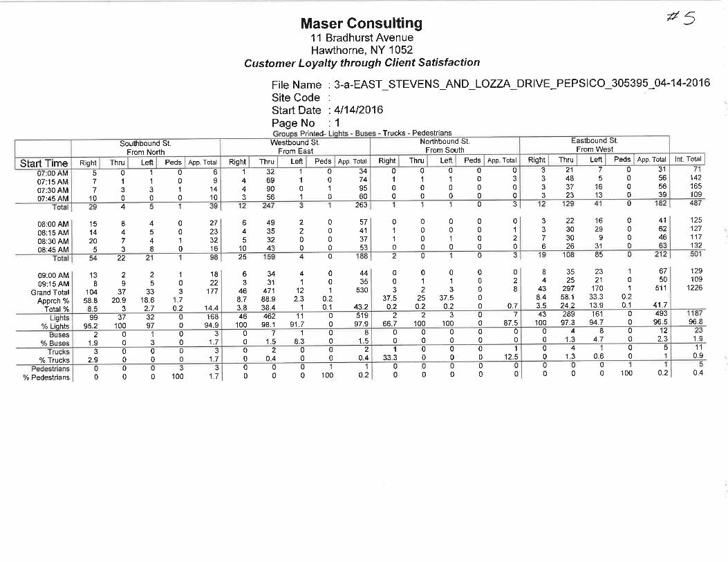
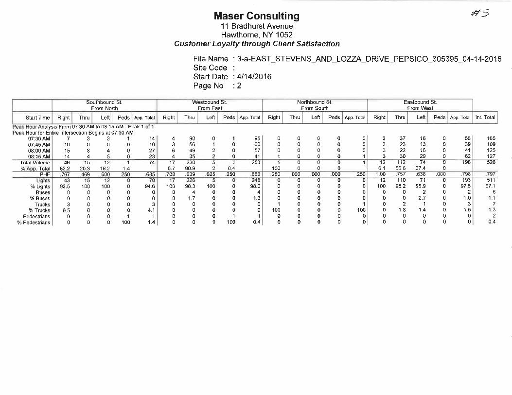
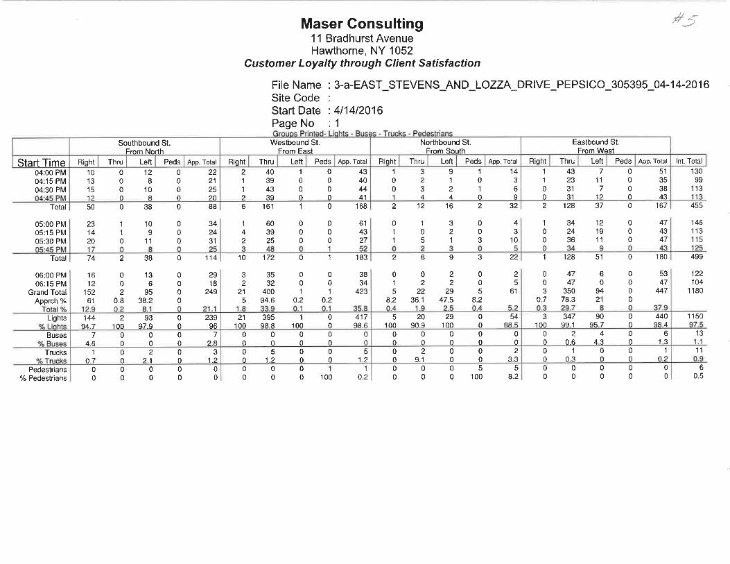
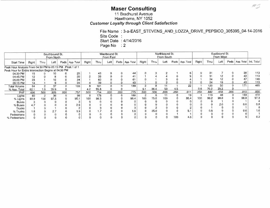
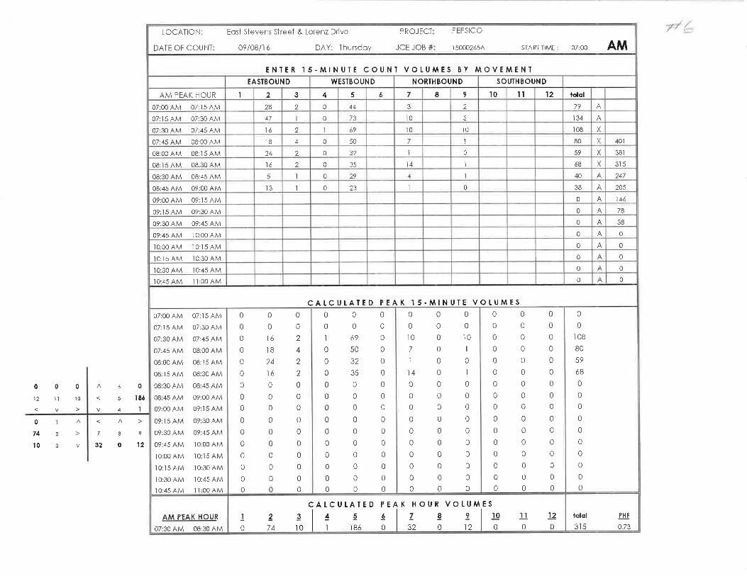
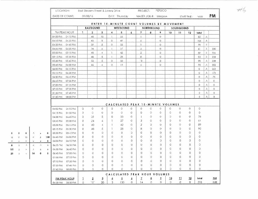
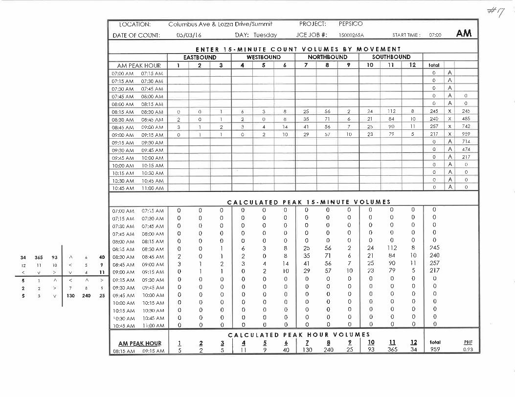
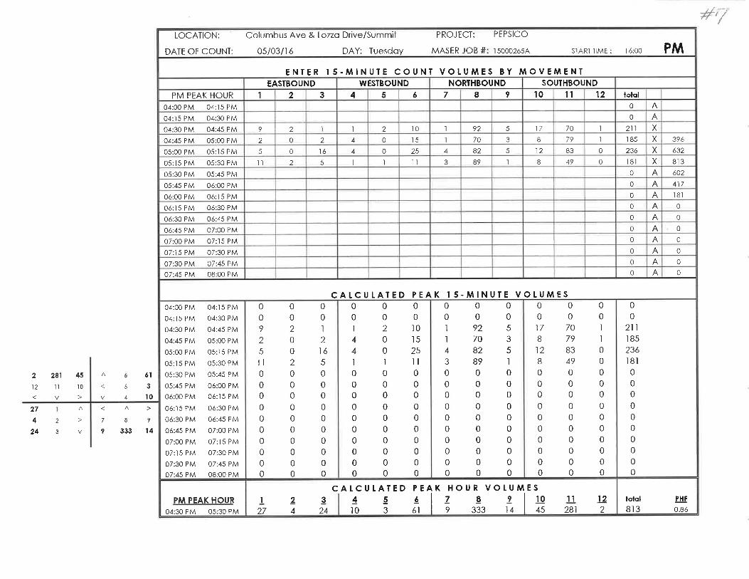

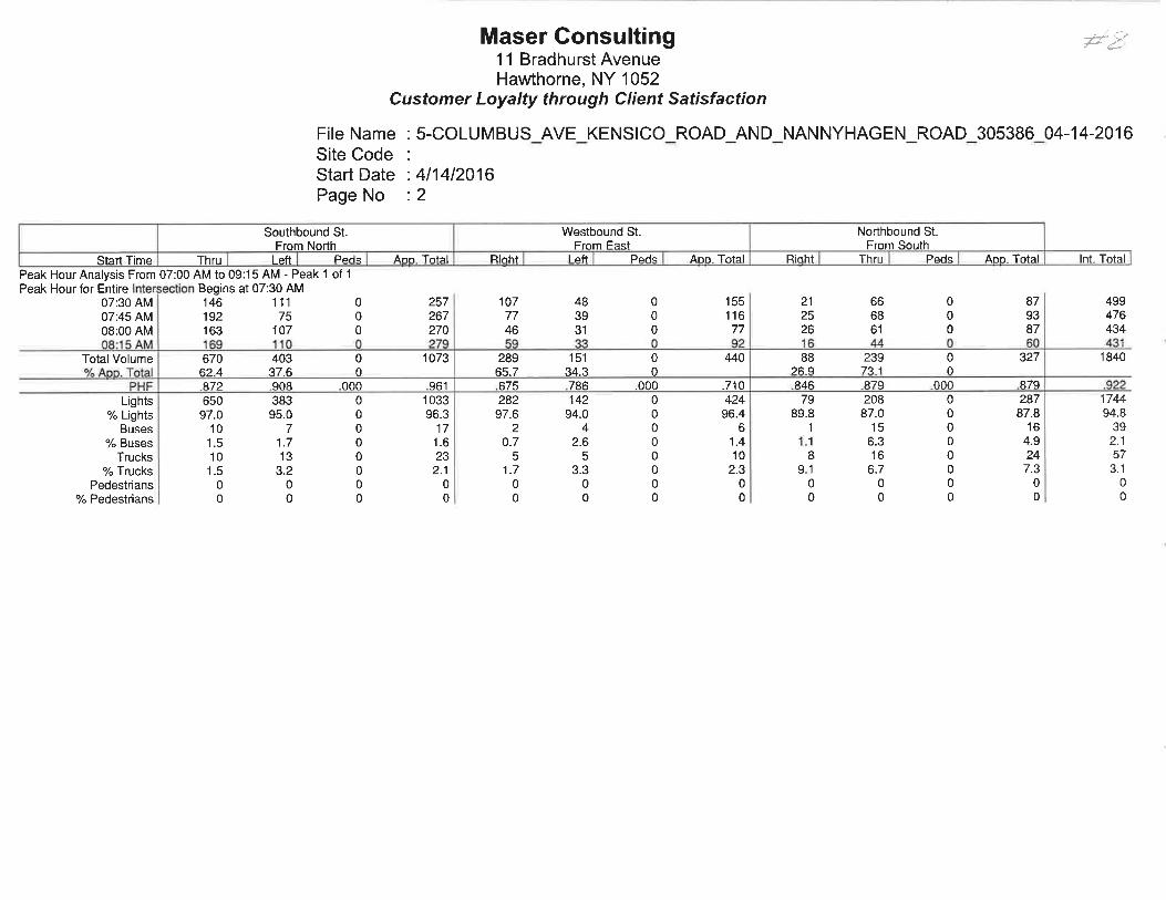
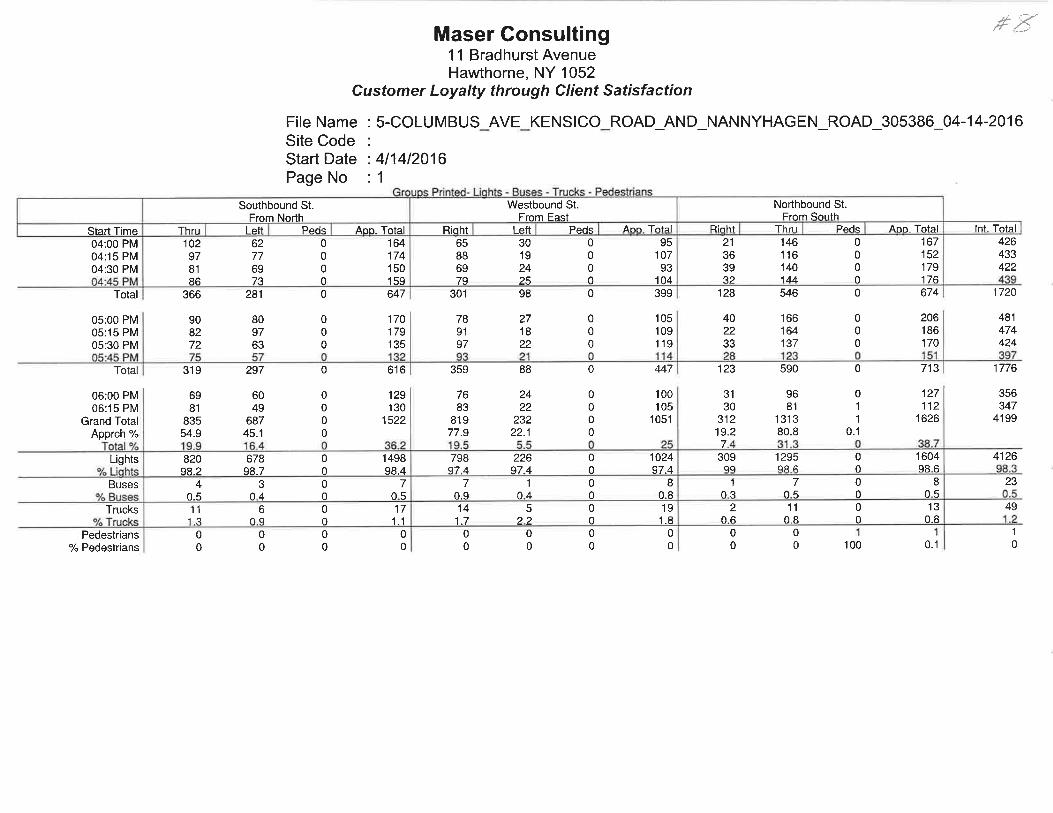

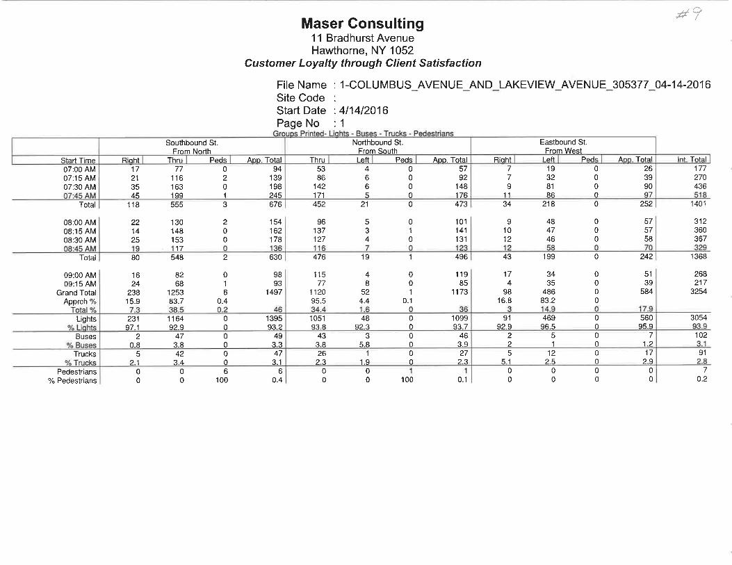
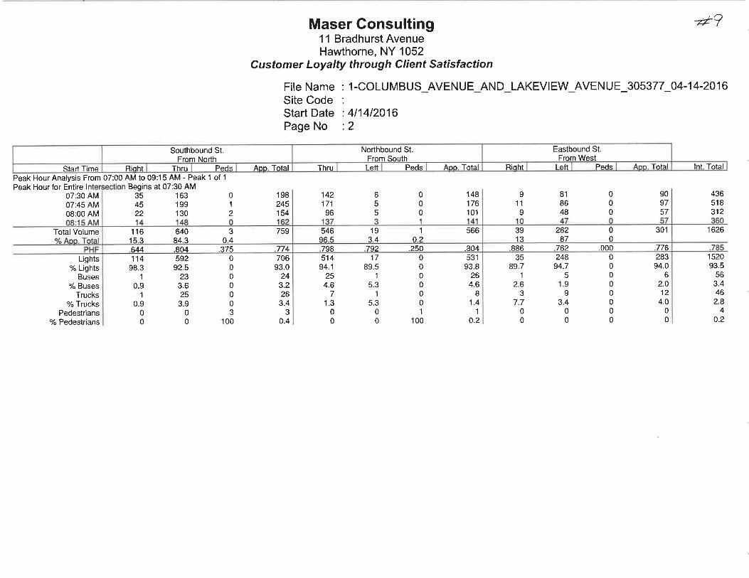
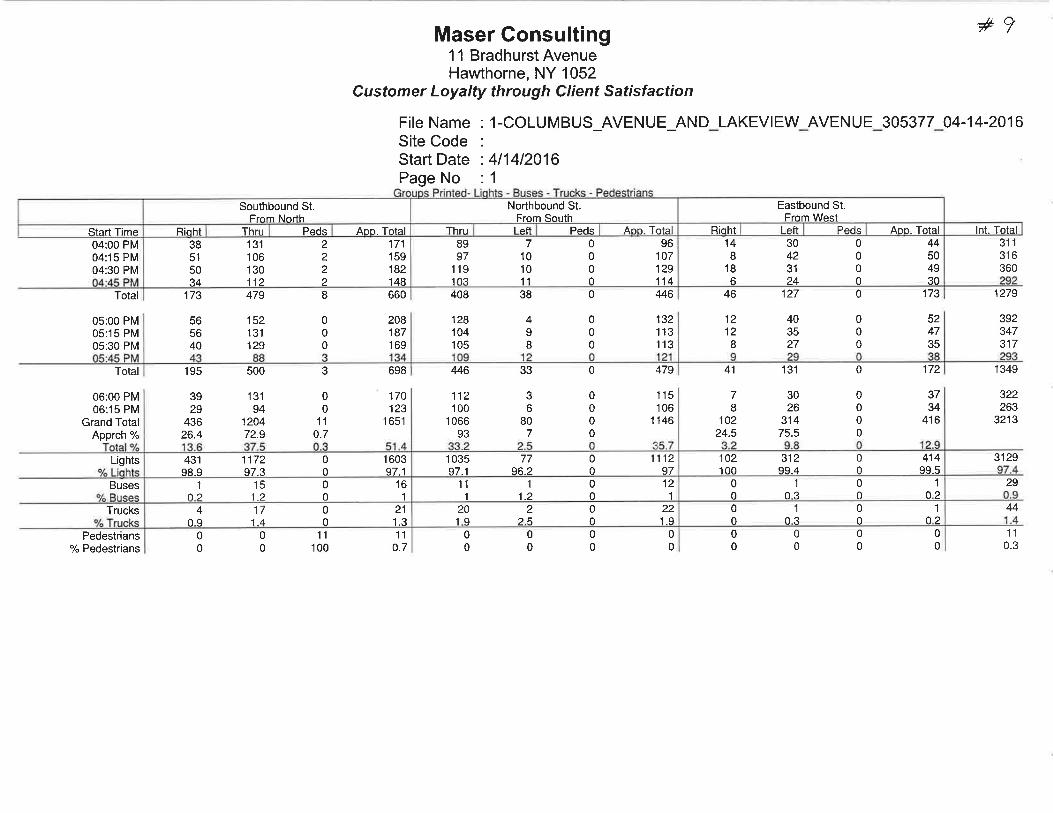
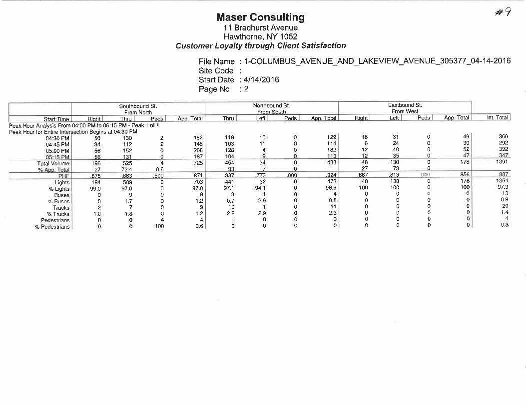
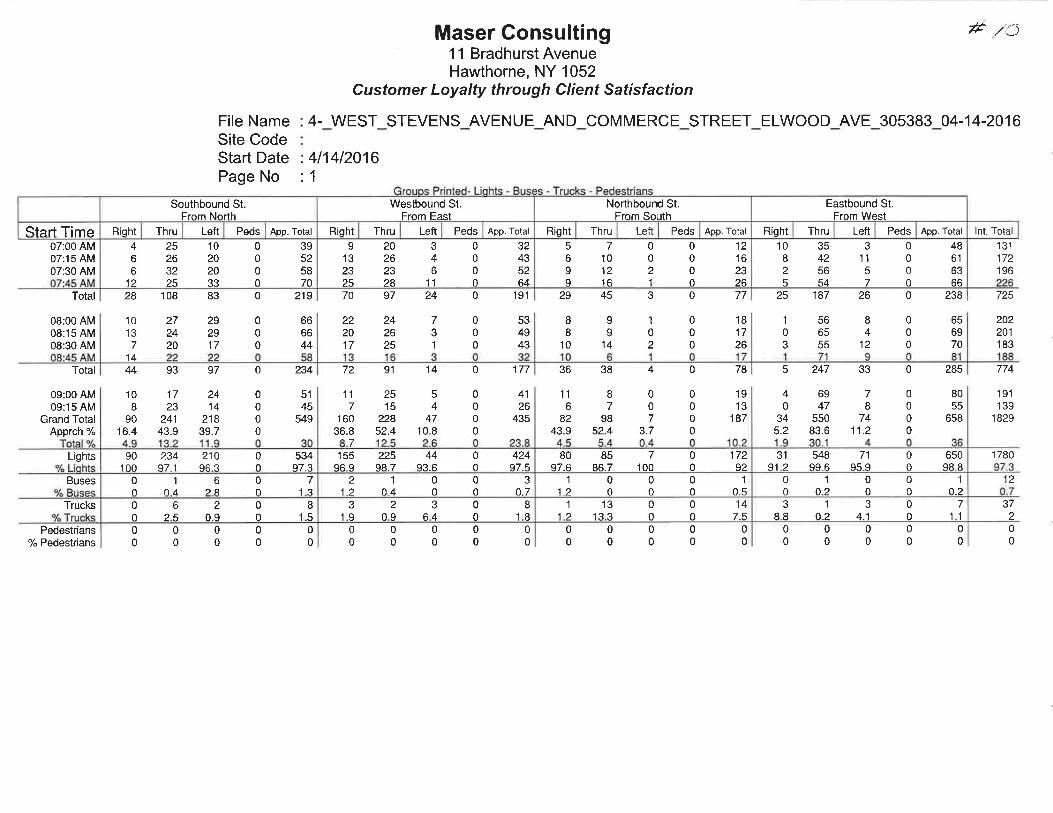
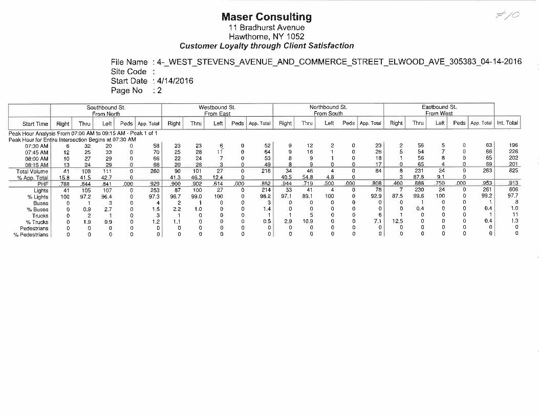
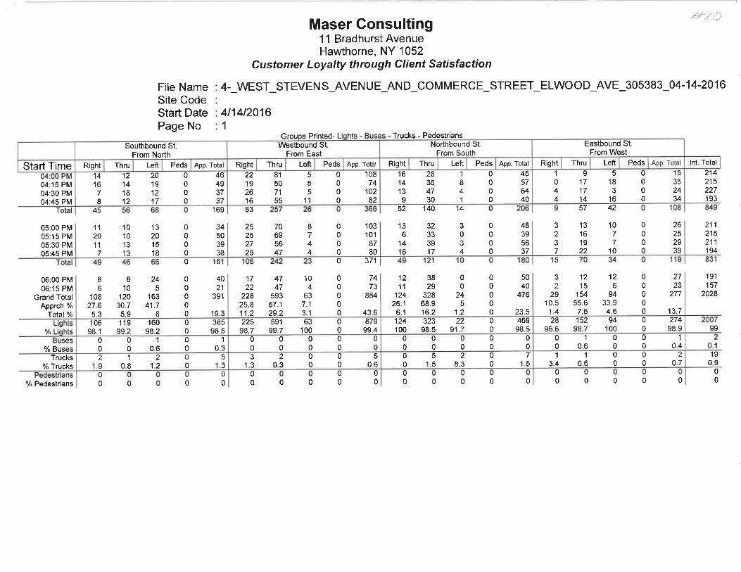
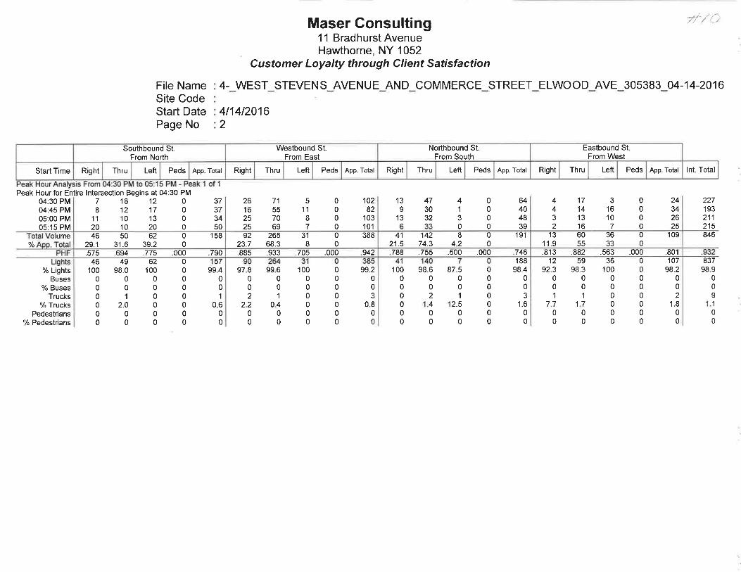
APPENDIX G
PRELIMINARY ASSESSMENT / DISTURBANCE
MEMORANDUM
1. Preliminary Report, dated November 2016, by
Historical Perspectives
1
HISTORICAL
PERSPECTIVES INC.
November 2016
Preliminary Assessment/Disturbance Memorandum
PepsiCo R&D Facility Expansion
350 Columbus Avenue and 100 East Stevens Avenue
Valhalla, Town of Mount Pleasant, Westchester County, New York
INTRODUCTION
PepsiCo, Inc. (PepsiCo) proposes a new development at its Research and Development campus at 350 Columbus
Avenue, Valhalla, Town of Mount Pleasant, Westchester County, New York (Figures 1, 2 and 3). The project site is
currently improved with a three-story office building and a two-story warehouse building/pilot plant facility,
together with related parking lots and other improvements. The proposed new development will include an
approximately 122,000 square-foot, three-story state-of-the-art research and development facility, together with a
new parking area, landscaping, and other associated site improvements (Figure 3). For the purposes of this study, all
of the locations within the project site slated for new development or other ground disturbance are considered the
Area of Potential Effect (APE).
At the request of PepsiCo, Historical Perspectives, Inc. (HPI) has undertaken the following Preliminary
Assessment/Disturbance Record study of the proposed site in order to: 1) identify categories of potential
archaeological resources on the project site; 2) examine the construction history of the project site in order to
determine the probability that any potential archaeological resources have survived post-depositional disturbances
and remain on the site; and 3) determine whether additional research, in the form of a Phase IA study may be
necessary.
METHODOLOGY
The present study entailed a review of various resources:
Historic maps were reviewed from the collections of the Map Division of the New York Public Library,
and using various online websites. These maps provided an overview of the topography and a chronology
of land usage for the study site.
Previously recorded archaeological sites were reviewed using data from the New York State Office of
Parks, Recreation, and Historic Preservation (NYSOPRHP).
Primary and secondary sources relating to the project site and its vicinity were reviewed, including historic
newspapers and photographs.
Soil boring data for the project site were provided by PepsiCo.
Several survey maps and construction photographs of the project site were provided by PepsiCo.
Last, a site visit was conducted on September 30, 2016 to assess any obvious or unrecorded subsurface
disturbance (Photographs 1-10; Figure 2).
CURRENT CONDITIONS
The PepsiCo campus is approximately 35 acres in size. It is bounded on the north by East Stevens Avenue, on the
south by property of the Valhalla Unified School District, on the west by the northbound lanes of Columbus Avenue
and on the east by private property. The campus was constructed in the late 1970s, and presently contains a three-
2
story office building, a two-story warehouse building/pilot plant facility, parking lots, driveways, and other
improvements. The campus has entrances on both Columbus Avenue and East Stevens Avenue that connect via a
looping drive (Photographs 1-3). The area at the northwest corner of the campus contains ball fields that were
constructed by grading the naturally sloping landform to create a level surface (Photographs 4 and 5). The highest
point on the property is south of East Stevens Avenue, where a number of structures once stood. Today this area
contains a surface parking lot and an associated subsurface infiltration system to collect excess runoff (Photographs
6 and 7). The only former structure that is still partially extant is a former swimming pool that has been filled in
(Photograph 8). The project also includes reconfiguration of existing surface parking lots and driveways on the
southern portion of the property (Photographs 9 and 10). Wetlands and a drainage are located on the eastern portion
of the campus.
TOPOGRAPHY AND HYDROLOGY
The earliest available topographic map that notes elevations indicates that in its original state, the project site
contained a gently to moderately sloping landform, with a north-south oriented terrace roughly bisecting the
property. Historic occupation, along with an entry driveway, was situated along this terrace landform. Elevations
on the site ranged from approximately 380 feet above sea level at the southwest corner of the property to
approximately 460 feet at the entry drive on East Stevens Avenue (U.S.G.S. 1938, Figure 6). There has been
significant earthmoving on the site since the late 1970s, however, and today although some elevations are similar to
pre-construction conditions, the shape of the landform has been altered in many places from its natural state (Figure
2).
There is a stream that runs north-south through the eastern side of the project site. It is surrounded in places by
wetlands. Prior to construction of Kensico Reservoir, the stream emptied into the Bronx River. This stream has
been modified to create a stormwater basin.
SOILS
There are a number of soils mapped for the project site (U.S.D.A. 2016). These soils are described in Table 1,
below. The area containing the ball fields south of East Stevens Avenue is mapped as Chatfield-Charlton complex,
hilly, very rocky. The area east of the entry drive on East Stevens Avenue is mapped as Paxton fine sandy loam and
further east, Ridgebury loam. The remainder of the project site is mapped as Udorthents and Urban Land, signifying
prior earthmoving.
Table 1: Soils mapped within the project site
Name Soil Horizon Depth
cm(in)
Texture,
Inclusions
Slope
%
Drainage Landform
Chatfield-
Charlton
complex,
hilly, very
rocky (CrC)
0-7 in
7-24 in
24-28 in
Lo
FlaSiLo
Bedrock
15-35 Well Hills and ridges
Paxton fine
sandy loam
(PnC)
0-8 in
8-15 in
15-26 in
26-65 in
FiSaLo
FiSaLo
FiSaLo
GrlFiSaLo
8-15 Well Drumlins, ground
moraines, hills
Ridgebury
loam (RdA)
0-8 in
8-26 in
26-60 in
Lo
GrlFiSaLo
GrlLo
0-3 Poorly Depressions
Udorthents,
smoothed
(Ub)
0-4 in
4-70 in
GrlLo
VGrlLo
0-8 Moderately
well
N/A
Urban land
(Uf)
N/A N/A N/A N/A N/A
Key: Soils: Lo-Loam, Sa-Sand, Si-Silt
Other: Fi-Fine, Grl-Gravelly, V-Very
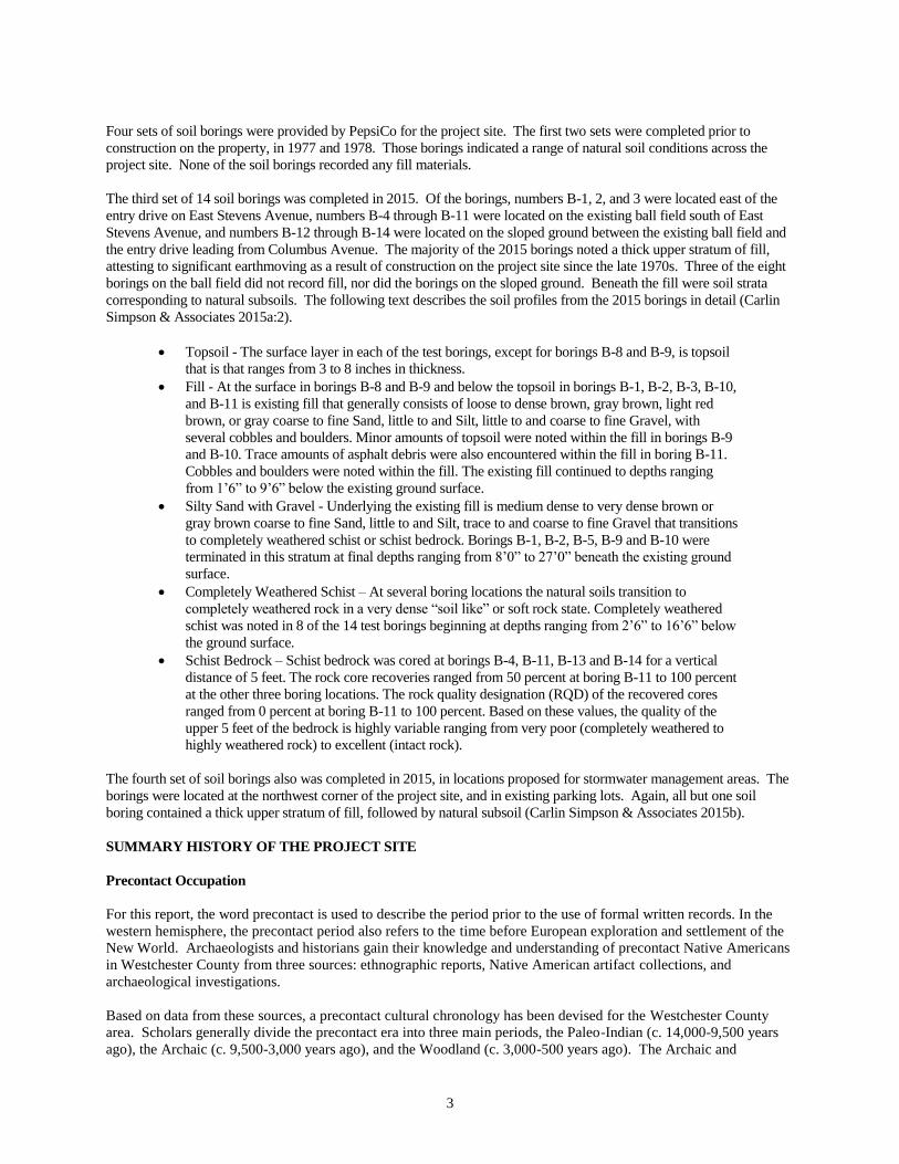
3
Four sets of soil borings were provided by PepsiCo for the project site. The first two sets were completed prior to
construction on the property, in 1977 and 1978. Those borings indicated a range of natural soil conditions across the
project site. None of the soil borings recorded any fill materials.
The third set of 14 soil borings was completed in 2015. Of the borings, numbers B-1, 2, and 3 were located east of the
entry drive on East Stevens Avenue, numbers B-4 through B-11 were located on the existing ball field south of East
Stevens Avenue, and numbers B-12 through B-14 were located on the sloped ground between the existing ball field and
the entry drive leading from Columbus Avenue. The majority of the 2015 borings noted a thick upper stratum of fill,
attesting to significant earthmoving as a result of construction on the project site since the late 1970s. Three of the eight
borings on the ball field did not record fill, nor did the borings on the sloped ground. Beneath the fill were soil strata
corresponding to natural subsoils. The following text describes the soil profiles from the 2015 borings in detail (Carlin
Simpson & Associates 2015a:2).
Topsoil - The surface layer in each of the test borings, except for borings B-8 and B-9, is topsoil
that is that ranges from 3 to 8 inches in thickness.
Fill - At the surface in borings B-8 and B-9 and below the topsoil in borings B-1, B-2, B-3, B-10,
and B-11 is existing fill that generally consists of loose to dense brown, gray brown, light red
brown, or gray coarse to fine Sand, little to and Silt, little to and coarse to fine Gravel, with
several cobbles and boulders. Minor amounts of topsoil were noted within the fill in borings B-9
and B-10. Trace amounts of asphalt debris were also encountered within the fill in boring B-11.
Cobbles and boulders were noted within the fill. The existing fill continued to depths ranging
from 1’6” to 9’6” below the existing ground surface.
Silty Sand with Gravel - Underlying the existing fill is medium dense to very dense brown or
gray brown coarse to fine Sand, little to and Silt, trace to and coarse to fine Gravel that transitions
to completely weathered schist or schist bedrock. Borings B-1, B-2, B-5, B-9 and B-10 were
terminated in this stratum at final depths ranging from 8’0” to 27’0” beneath the existing ground
surface.
Completely Weathered Schist – At several boring locations the natural soils transition to
completely weathered rock in a very dense “soil like” or soft rock state. Completely weathered
schist was noted in 8 of the 14 test borings beginning at depths ranging from 2’6” to 16’6” below
the ground surface.
Schist Bedrock – Schist bedrock was cored at borings B-4, B-11, B-13 and B-14 for a vertical
distance of 5 feet. The rock core recoveries ranged from 50 percent at boring B-11 to 100 percent
at the other three boring locations. The rock quality designation (RQD) of the recovered cores
ranged from 0 percent at boring B-11 to 100 percent. Based on these values, the quality of the
upper 5 feet of the bedrock is highly variable ranging from very poor (completely weathered to
highly weathered rock) to excellent (intact rock).
The fourth set of soil borings also was completed in 2015, in locations proposed for stormwater management areas. The
borings were located at the northwest corner of the project site, and in existing parking lots. Again, all but one soil
boring contained a thick upper stratum of fill, followed by natural subsoil (Carlin Simpson & Associates 2015b).
SUMMARY HISTORY OF THE PROJECT SITE
Precontact Occupation
For this report, the word precontact is used to describe the period prior to the use of formal written records. In the
western hemisphere, the precontact period also refers to the time before European exploration and settlement of the
New World. Archaeologists and historians gain their knowledge and understanding of precontact Native Americans
in Westchester County from three sources: ethnographic reports, Native American artifact collections, and
archaeological investigations.
Based on data from these sources, a precontact cultural chronology has been devised for the Westchester County
area. Scholars generally divide the precontact era into three main periods, the Paleo-Indian (c. 14,000-9,500 years
ago), the Archaic (c. 9,500-3,000 years ago), and the Woodland (c. 3,000-500 years ago). The Archaic and
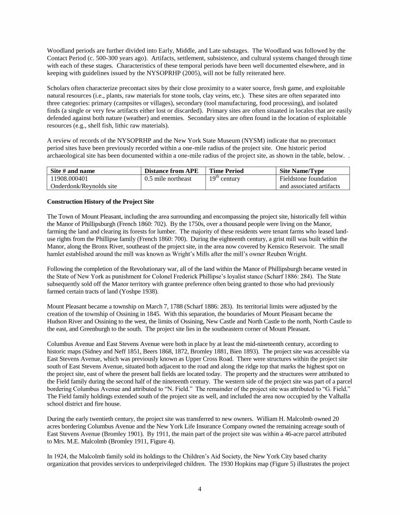
4
Woodland periods are further divided into Early, Middle, and Late substages. The Woodland was followed by the
Contact Period (c. 500-300 years ago). Artifacts, settlement, subsistence, and cultural systems changed through time
with each of these stages. Characteristics of these temporal periods have been well documented elsewhere, and in
keeping with guidelines issued by the NYSOPRHP (2005), will not be fully reiterated here.
Scholars often characterize precontact sites by their close proximity to a water source, fresh game, and exploitable
natural resources (i.e., plants, raw materials for stone tools, clay veins, etc.). These sites are often separated into
three categories: primary (campsites or villages), secondary (tool manufacturing, food processing), and isolated
finds (a single or very few artifacts either lost or discarded). Primary sites are often situated in locales that are easily
defended against both nature (weather) and enemies. Secondary sites are often found in the location of exploitable
resources (e.g., shell fish, lithic raw materials).
A review of records of the NYSOPRHP and the New York State Museum (NYSM) indicate that no precontact
period sites have been previously recorded within a one-mile radius of the project site. One historic period
archaeological site has been documented within a one-mile radius of the project site, as shown in the table, below. .
Site # and name Distance from APE Time Period Site Name/Type
11908.000401
Onderdonk/Reynolds site
0.5 mile northeast 19th
century Fieldstone foundation
and associated artifacts
Construction History of the Project Site
The Town of Mount Pleasant, including the area surrounding and encompassing the project site, historically fell within
the Manor of Phillipsburgh (French 1860: 702). By the 1750s, over a thousand people were living on the Manor,
farming the land and clearing its forests for lumber. The majority of these residents were tenant farms who leased land-
use rights from the Phillipse family (French 1860: 700). During the eighteenth century, a grist mill was built within the
Manor, along the Bronx River, southeast of the project site, in the area now covered by Kensico Reservoir. The small
hamlet established around the mill was known as Wright’s Mills after the mill’s owner Reuben Wright.
Following the completion of the Revolutionary war, all of the land within the Manor of Phillipsburgh became vested in
the State of New York as punishment for Colonel Frederick Phillipse’s loyalist stance (Scharf 1886: 284). The State
subsequently sold off the Manor territory with grantee preference often being granted to those who had previously
farmed certain tracts of land (Yoshpe 1938).
Mount Pleasant became a township on March 7, 1788 (Scharf 1886: 283). Its territorial limits were adjusted by the
creation of the township of Ossining in 1845. With this separation, the boundaries of Mount Pleasant became the
Hudson River and Ossining to the west, the limits of Ossining, New Castle and North Castle to the north, North Castle to
the east, and Greenburgh to the south. The project site lies in the southeastern corner of Mount Pleasant.
Columbus Avenue and East Stevens Avenue were both in place by at least the mid-nineteenth century, according to
historic maps (Sidney and Neff 1851, Beers 1868, 1872, Bromley 1881, Bien 1893). The project site was accessible via
East Stevens Avenue, which was previously known as Upper Cross Road. There were structures within the project site
south of East Stevens Avenue, situated both adjacent to the road and along the ridge top that marks the highest spot on
the project site, east of where the present ball fields are located today. The property and the structures were attributed to
the Field family during the second half of the nineteenth century. The western side of the project site was part of a parcel
bordering Columbus Avenue and attributed to “N. Field.” The remainder of the project site was attributed to “G. Field.”
The Field family holdings extended south of the project site as well, and included the area now occupied by the Valhalla
school district and fire house.
During the early twentieth century, the project site was transferred to new owners. William H. Malcolmb owned 20
acres bordering Columbus Avenue and the New York Life Insurance Company owned the remaining acreage south of
East Stevens Avenue (Bromley 1901). By 1911, the main part of the project site was within a 46-acre parcel attributed
to Mrs. M.E. Malcolmb (Bromley 1911, Figure 4).
In 1924, the Malcolmb family sold its holdings to the Children’s Aid Society, the New York City based charity
organization that provides services to underprivileged children. The 1930 Hopkins map (Figure 5) illustrates the project
5
site during the period it was owned by the Children’s Aid Society. The “Martha Home” was a group home that served as
a convalescent facility for boys under the age of 12. There were several “Martha Homes” throughout the New York City
region. The 1938 U.S.G.S. map (Figure 6) also labels the main building on the property as the “Martha Home.”
The Children’s Aid Society owned the project site until 1967; in 1969 the current owner, PepsiCo, purchased the
property. That same year, a survey was made of the property indicating the existing structures on the site (Figure 7). At
the time, there were four buildings on the site, two immediately south of East Stevens Avenue and two further towards
the interior of the property and accessed by a long driveway. Three of the buildings appear to have been residences, and
the fourth was a garage. The Martha Home was the southernmost of the residences. The filled-in former swimming
pool observed during the site visit was located just west of the Martha Home. It is the only visible remain that attests to
the former use of the project site.
After PepsiCo purchased the project site, all of the former structures on the property were removed. Figure 7 was
annotated by PepsiCo at a later date to indicate that two of the buildings burned down and two were demolished. The
PepsiCo site plan for the property was approved by the Town of Mount Pleasant in 1977, and construction of the campus
began shortly thereafter. The 1977 site plan that was approved included a proposed building and associated surface
parking lots in the northwest quadrant of the property, in the approximate location of the present ball fields. Photographs
of the property during construction reveal significant earthmoving to create the present office park setting (Photographs
11 and 12).
The late 1970s construction on the project site included the two present office buildings, the entry driveways, the parking
areas, and the site infrastructure. The existing ball fields in the northwest quadrant of the project site were created in the
1990s, and involved extensive grading and filling to create the generally level fields from the naturally sloping landform.
The most recent construction on the site was in 2008, when the surface parking lot and subsurface infiltration system was
created just west of the East Stevens Avenue entry drive.
CONCLUSIONS
Disturbance Record
The project site has been very heavily disturbed from earthmoving associated with construction of the present PepsiCo
office park buildings and its associated driveways, parking lots, ball fields, and subsurface utility infrastructure. Soil
borings indicate large amounts of fill throughout the property, capping natural subsoils. There is no indication from the
soil borings that any natural upper soil strata, such as a buried A horizon, still exist on the project site. Further, other than
the infilled former swimming pool, there is no visible evidence of any historic structures or associated features on the
project site that predate the PepsiCo construction in the 1970s.
Precontact Sensitivity
From what is known of precontact period settlement patterns in Westchester County, most habitation and processing
sites are found in sheltered, elevated sites close to wetland features, major waterways, and with nearby sources of fresh
water. The project site contains a natural drainage and wetlands on its eastern side, which normally could indicate
precontact sensitivity. However, based on the later degree of significant landform manipulation and disturbance to the
property, HPI concludes that today the project site has minimal precontact sensitivity. Therefore, further research and
study concerning precontact archaeological resources is not recommended.
Historical Sensitivity
The project site formerly contained several historical structures dating at least to the nineteenth century, south of East
Stevens Avenue. However, as noted above, the significant earthmoving associated with construction of the PepsiCo
campus has removed any visible evidence of these resources, and it is likely that no intact subsurface remains have
survived this extensive landform manipulation. Therefore, further research and study concerning historic period
archaeological resources is not recommended.

6
RECOMMENDATIONS
Based on the above conclusions, HPI recommends no further archaeological investigations are necessary for the project
site.
7
BIBLIOGRAPHY
Beers, Elias Soule
1868 Atlas of New York and Vicinity. E. Beers and Company, New York.
1872 County Atlas of Westchester. E. Beers and Company, New York.
Bien, Julius
1893 Town of North Castle.
Bromley, George Washington
1881 Atlas of Westchester County. George W. and Walter S. Bromley. G.W. Bromley and Company,
Philadelphia.
1901 Atlas of Westchester County, New York. George W. and Walter S. Bromley. G.W. Bromley and Company,
Philadelphia.
1911 Atlas of Westchester County, New York. Bromley & Co., New York.
Carlin Simpson & Associates
2015a Geotechnical Memo: Project Eden, Pepsi – Valhalla Campus, Valhalla, New York. Prepared for JMC.
2015b Geotechnical Memo: Project Eden, Pepsi – Valhalla Campus, Valhalla, New York. Prepared for JMC.
French, J.H.
1860 Gazetteer of the State of New York. Westchester County, NY.
Hopkins, G.M. Company
1930 Atlas of Westchester County, New York. Hopkins Company, Philadelphia.
John Meyer Consultants
2016 Project site maps.
New York Archaeological Council (NYAC)
1994 Standards for Cultural Resource Investigations and the Curation of Archaeological Collections. New
York Archaeological Council.
New York State Office of Parks, Recreation, and Historic Preservation (NYSOPRHP)
2005 Phase I Archaeological Report Format Requirements.
Scharf, J. Thomas
1886 History of Westchester County, New York. Two volumes. Picton Press, Maine. L.E. Preston and
Company, Philadelphia.
Sidney, J.C and Neff.
1851 Map of Westchester County, New York. Map on file at the Tarrytown Historical Society, Tarrytown, New
York.
United States Department of Agriculture (U.S.D.A.)
2016 Web Soil Survey. Available online at http://websoilsurvey.nrcs.usda.gov/. Accessed September 22, 2016.
Natural Resources Conservation Service, United States Department of Agriculture.
United States Geological Survey (U.S.G.S.)
1938 Topographic Map, White Plains, New York, Quadrangle. 7.5 Minute Series. Surveyed 1932, printed 1938.
United States Geological Survey, U.S. Department of the Interior.

8
2016 Topographic Map, White Plains, New York Quadrangle. 7.5 Minute Series. United States Geological
Survey, U.S. Department of the Interior.
Yoshpe, Harry B.
1938 The Disposition of Philipse Manor After the Revolution. Quarterly Bulletin of the Westchester County
Historical Society 14(4): 87-88.
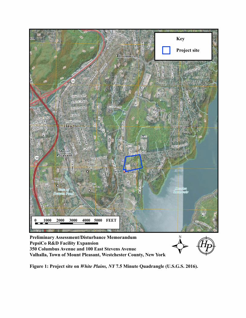
Preliminary Assessment/Disturbance MemorandumPepsiCo R&D Facility Expansion350 Columbus Avenue and 100 East Stevens AvenueValhalla, Town of Mount Pleasant, Westchester County, New York
Figure 1: Project site on White Plains, NY 7.5 Minute Quadrangle (U.S.G.S. 2016).
0 1000 2000 3000 4000 5000 FEET
Key
Project site
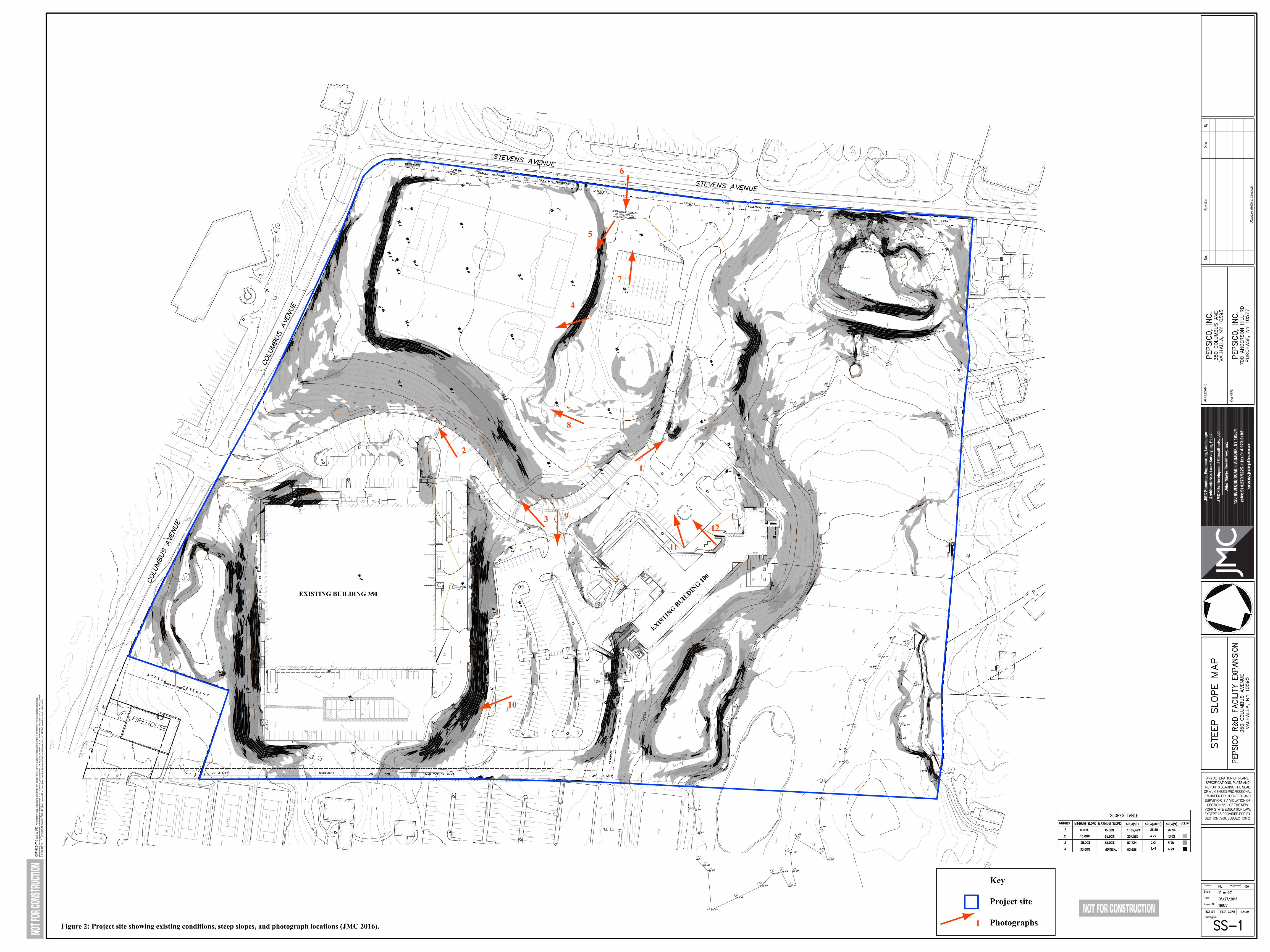
Drawing No:
Project No:
Date:
Scale:
Drawn: Approved:
ANY ALTERATION OF PLANS,SPECIFICATIONS, PLATS ANDREPORTS BEARING THE SEAL
OF A LICENSED PROFESSIONALENGINEER OR LICENSED LANDSURVEYOR IS A VIOLATION OF
SECTION 7209 OF THE NEWYORK STATE EDUCATION LAW,EXCEPT AS PROVIDED FOR BYSECTION 7209, SUBSECTION 2.
OWNE
R:
APPL
ICAN
T:No
.Re
vision
Date
By
COPY
RIGH
T ©
2016
by JM
CAl
l Righ
ts Re
serve
d. N
o par
t of th
is do
cume
nt ma
y be r
epro
duce
d, sto
red i
n a re
trieva
l sys
tem, o
r tra
nsmi
tted i
n any
form
or by
mea
ns, e
lectro
nic, m
echa
nical,
photo
copy
ing, r
ecor
ding o
r othe
rwise
, with
out th
e prio
r writt
en pe
rmiss
ion of
JMC
PLAN
NING
, ENG
INEE
RING
, LAN
DSCA
PE A
RCHI
TECT
URE
& LA
ND S
URVE
YING
, PLL
C | J
MC S
ITE
DEVE
LOPM
ENT
CONS
ULTA
NTS,
LLC
| JOH
N ME
YER
CONS
ULTI
NG, IN
C. (J
MC).
Any
mod
ificati
ons o
r alte
ratio
ns to
this
docu
ment
witho
ut the
writt
en pe
rmiss
ion of
JMC
shall
rend
er th
em in
valid
and u
nusa
ble.
053 GNIDLIUB GNITSIXE
EXISTIN
G BUILDIN
G 100
Figure 2: Project site showing existing conditions, steep slopes, and photograph locations (JMC 2016).
Key
Project site
Photographs1
7
8
9
10
6
5
4
3
2
1
11
12
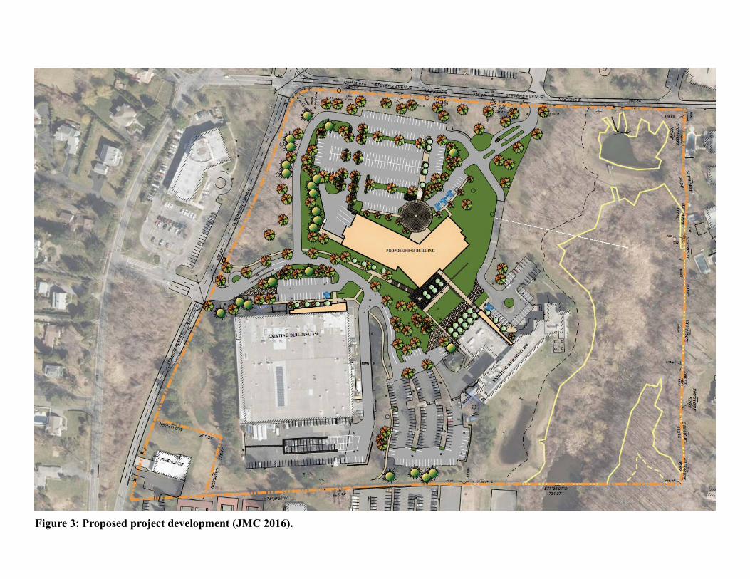
Figure 3: Proposed project development (JMC 2016).
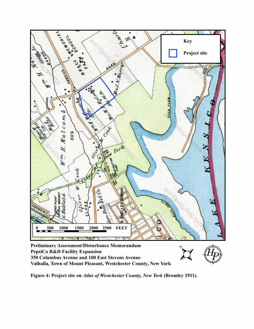
Preliminary Assessment/Disturbance MemorandumPepsiCo R&D Facility Expansion350 Columbus Avenue and 100 East Stevens AvenueValhalla, Town of Mount Pleasant, Westchester County, New York
Figure 4: Project site on Atlas of Westchester County, New York (Bromley 1911).
0 500 1000 1500 2000 2500 FEET
Key
Project site
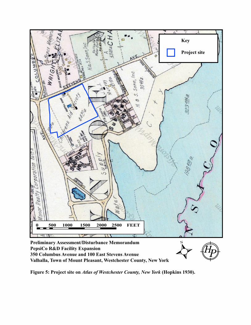
Preliminary Assessment/Disturbance MemorandumPepsiCo R&D Facility Expansion350 Columbus Avenue and 100 East Stevens AvenueValhalla, Town of Mount Pleasant, Westchester County, New York
Figure 5: Project site on Atlas of Westchester County, New York (Hopkins 1930).
0 500 1000 1500 2000 2500 FEET
Key
Project site
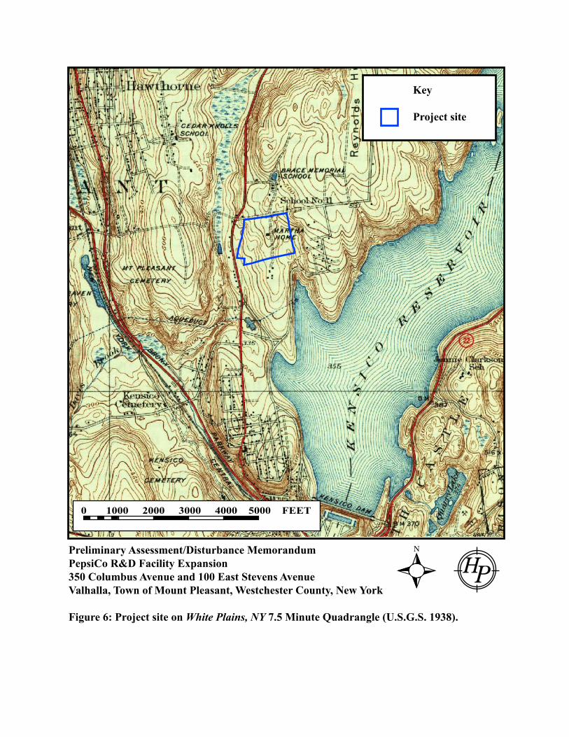
Preliminary Assessment/Disturbance MemorandumPepsiCo R&D Facility Expansion350 Columbus Avenue and 100 East Stevens AvenueValhalla, Town of Mount Pleasant, Westchester County, New York
Figure 6: Project site on White Plains, NY 7.5 Minute Quadrangle (U.S.G.S. 1938).
0 1000 2000 3000 4000 5000 FEET
Key
Project site
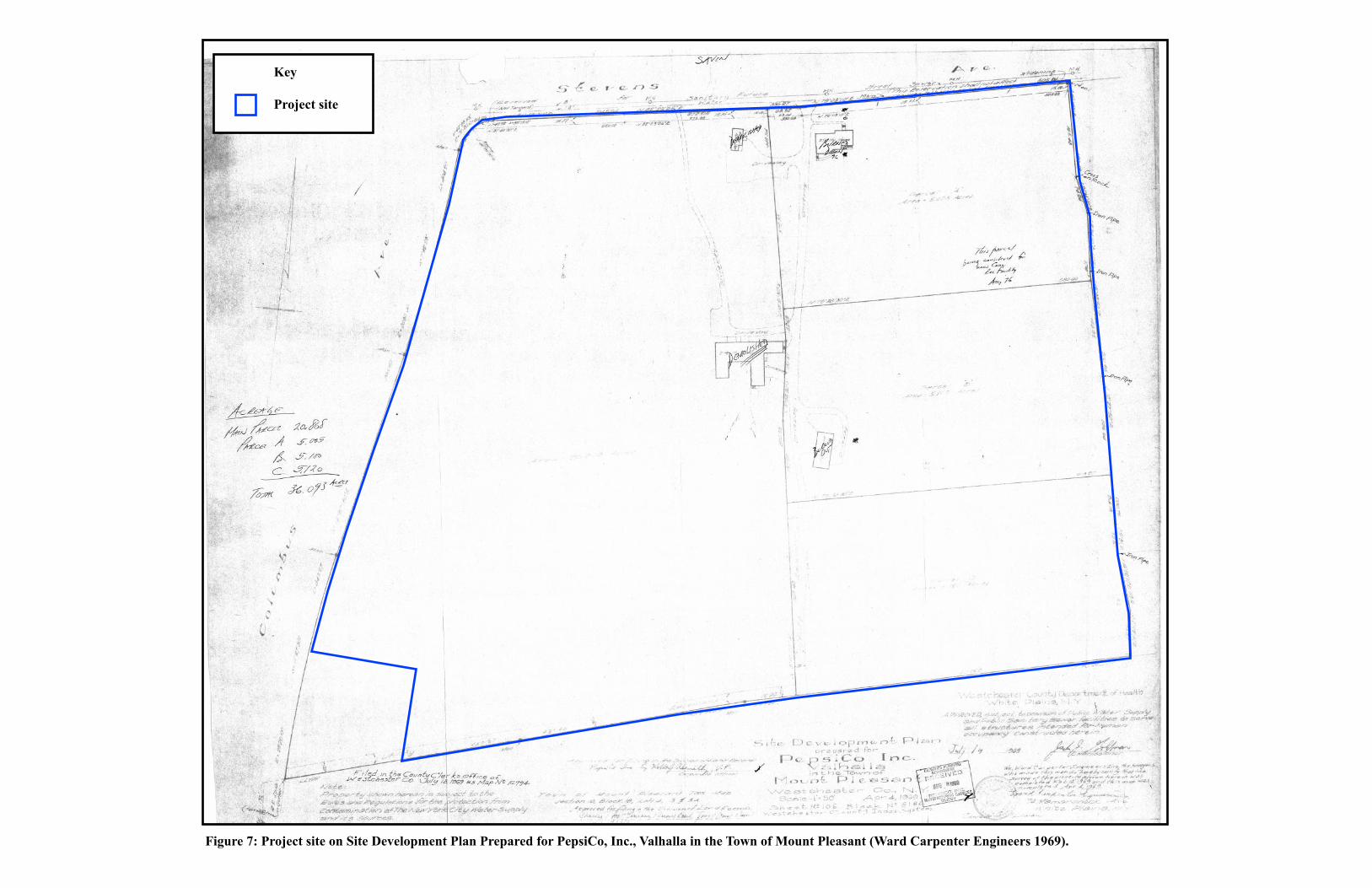
Figure 7: Project site on Site Development Plan Prepared for PepsiCo, Inc., Valhalla in the Town of Mount Pleasant (Ward Carpenter Engineers 1969).
Key
Project site
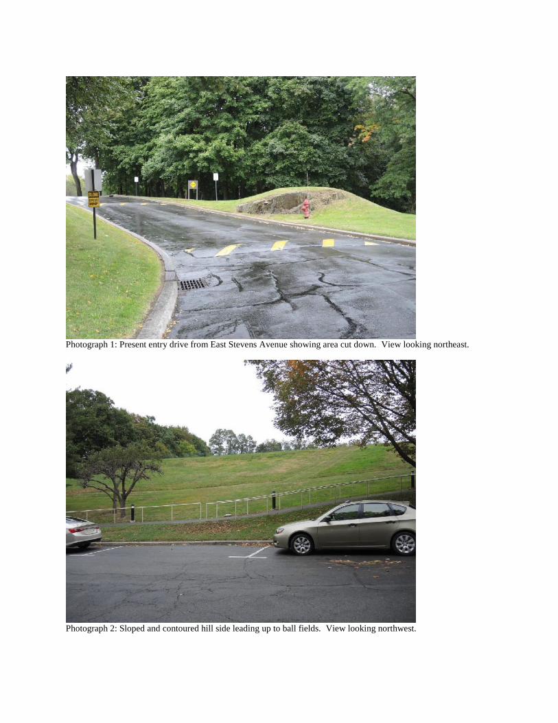
Photograph 1: Present entry drive from East Stevens Avenue showing area cut down. View looking northeast.
Photograph 2: Sloped and contoured hill side leading up to ball fields. View looking northwest.
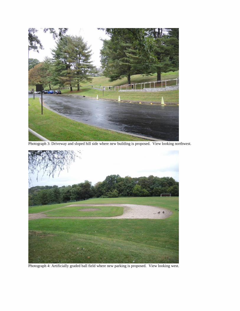
Photograph 3: Driveway and sloped hill side where new building is proposed. View looking northwest.
Photograph 4: Artificially graded ball field where new parking is proposed. View looking west.
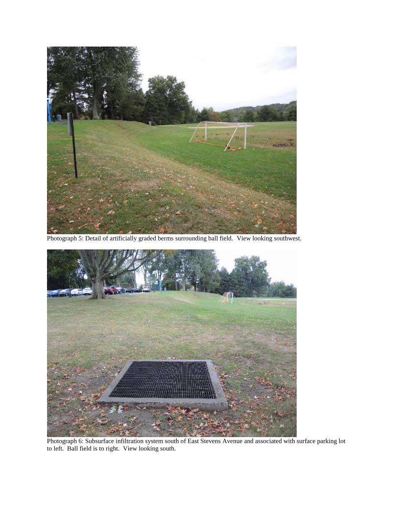
Photograph 5: Detail of artificially graded berms surrounding ball field. View looking southwest.
Photograph 6: Subsurface infiltration system south of East Stevens Avenue and associated with surface parking lot
to left. Ball field is to right. View looking south.
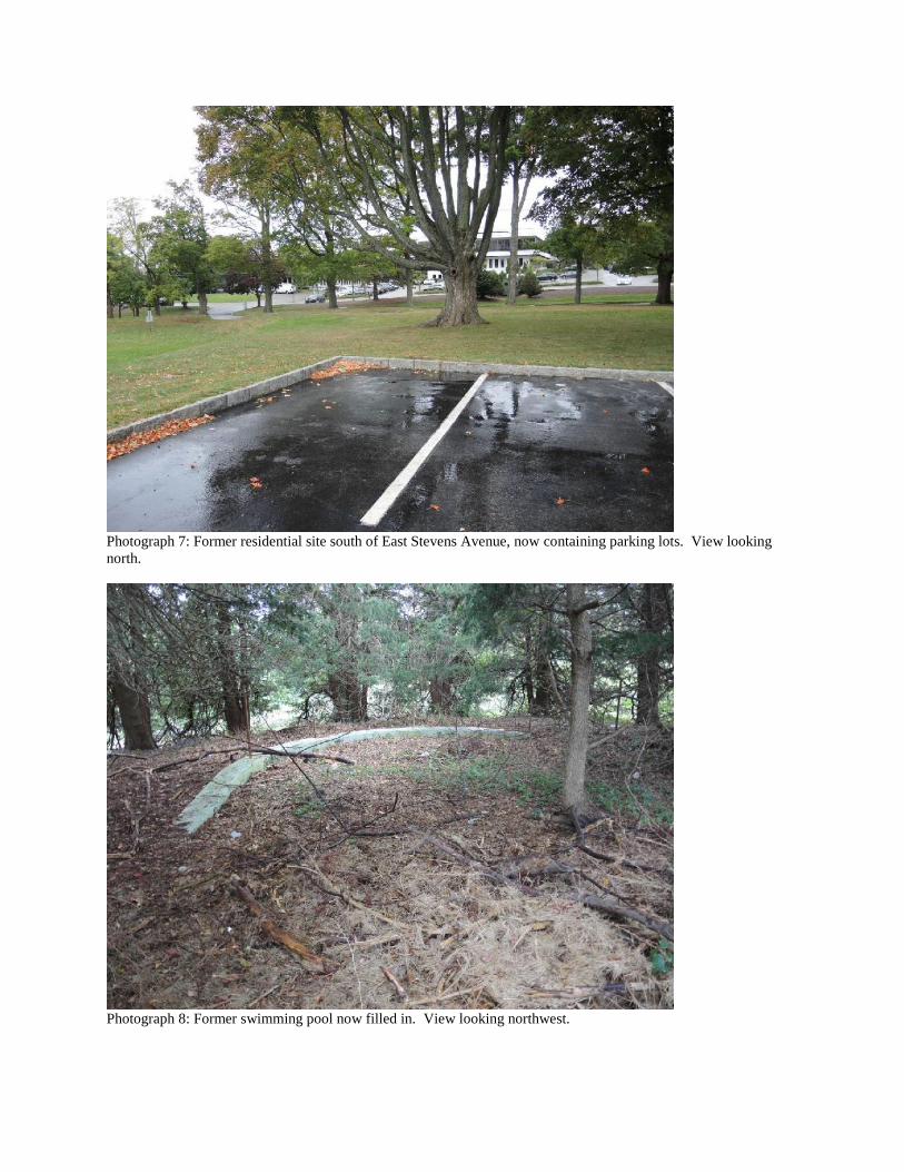
Photograph 7: Former residential site south of East Stevens Avenue, now containing parking lots. View looking
north.
Photograph 8: Former swimming pool now filled in. View looking northwest.
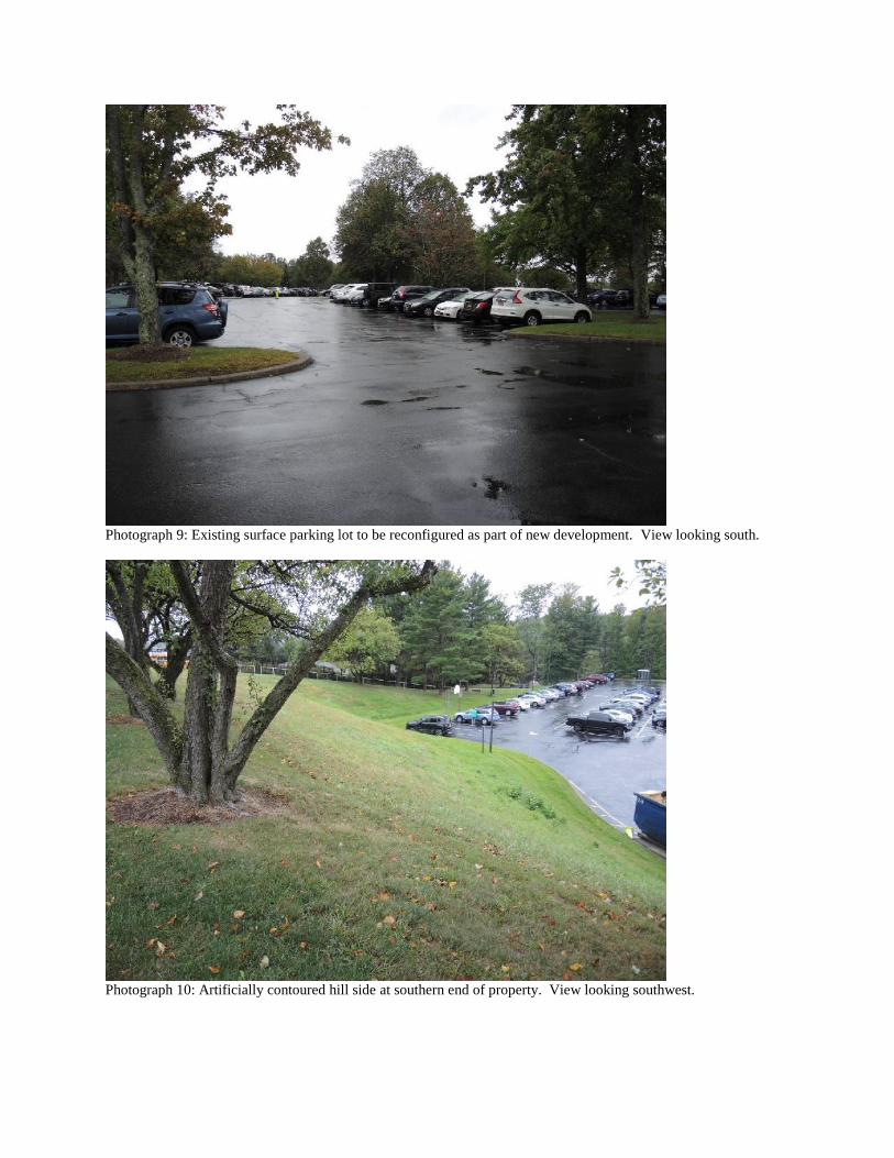
Photograph 9: Existing surface parking lot to be reconfigured as part of new development. View looking south.
Photograph 10: Artificially contoured hill side at southern end of property. View looking southwest.
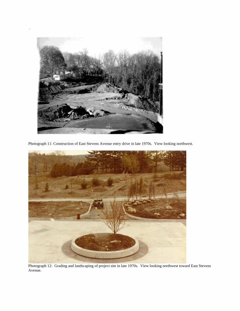
Photograph 11: Construction of East Stevens Avenue entry drive in late 1970s. View looking northwest.
Photograph 12: Grading and landscaping of project site in late 1970s. View looking northwest toward East Stevens
Avenue.
APPENDIX H
AIR FACILITY REGISTRATION CERTIFICATE
1. NYSDEC Air Facility Registration Certificate,
effective January 14, 2013
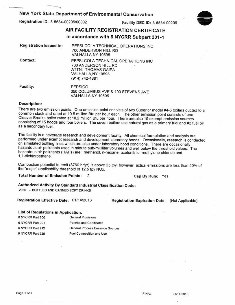
APPENDIX I
VALHALLA FIRE DEPARTMENTPARCEL DOCUMENTATION
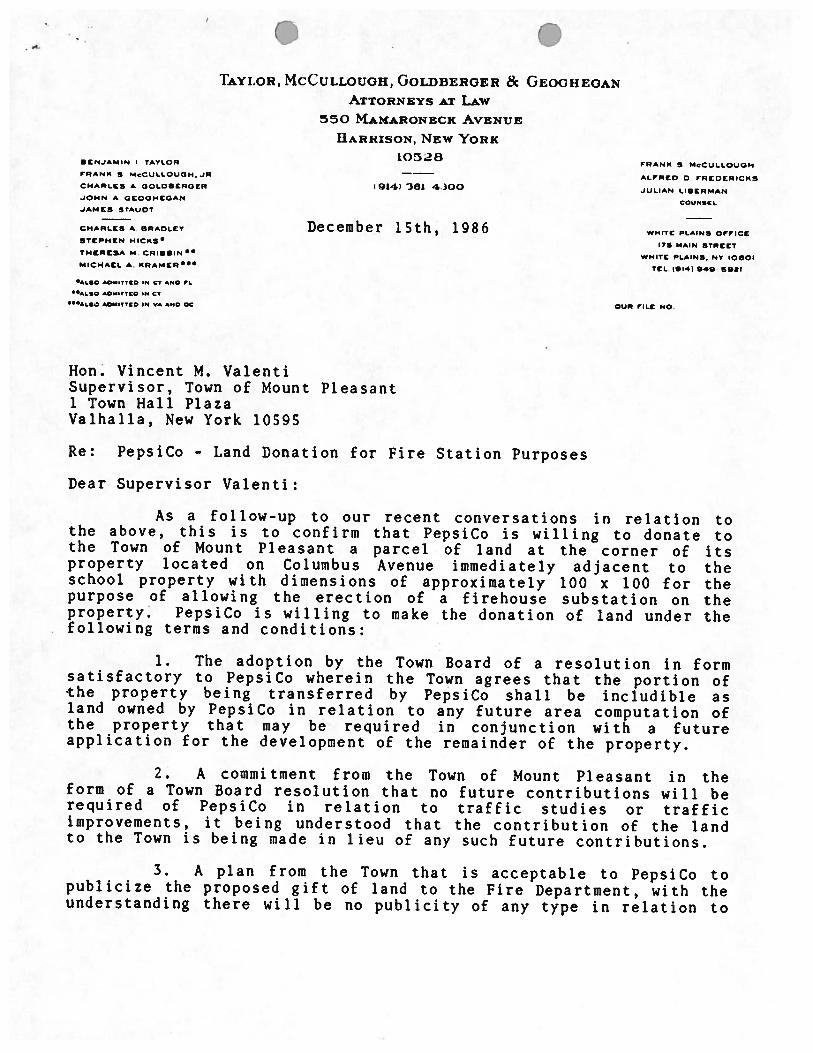
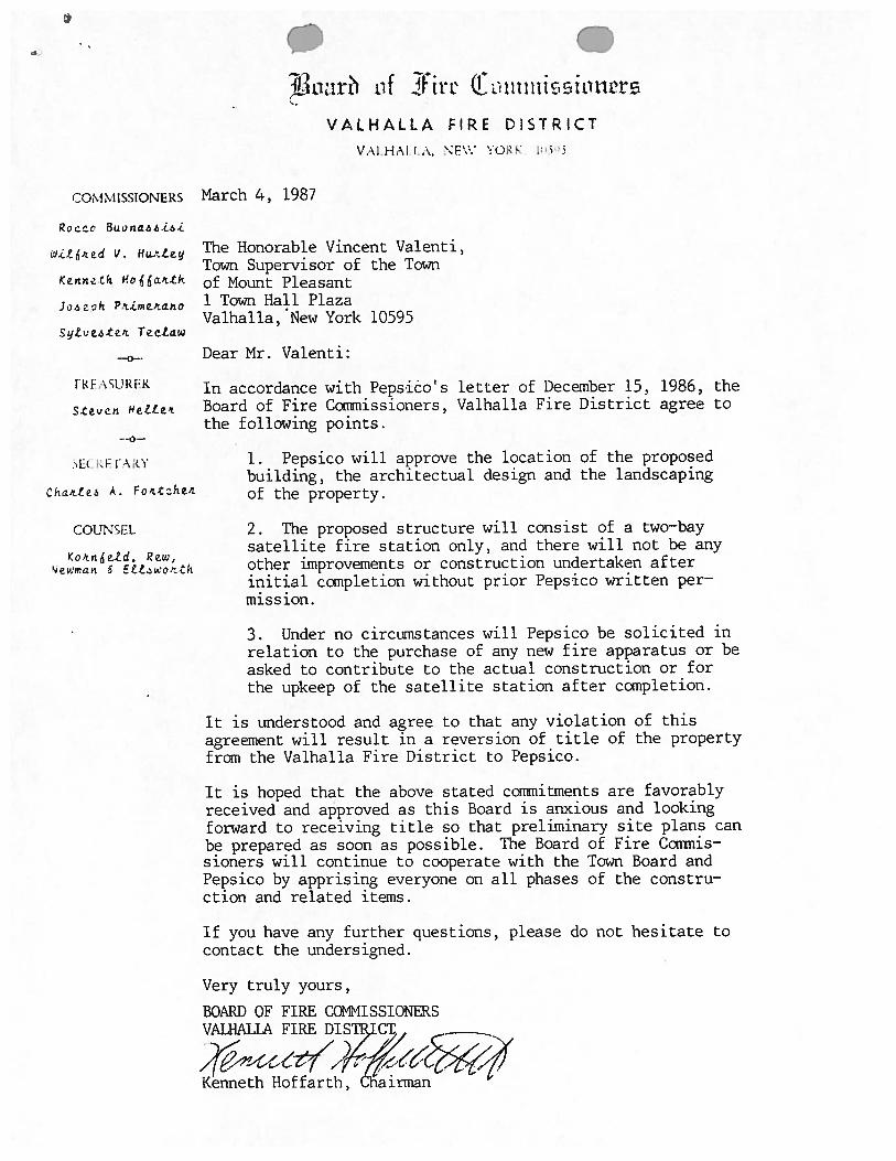
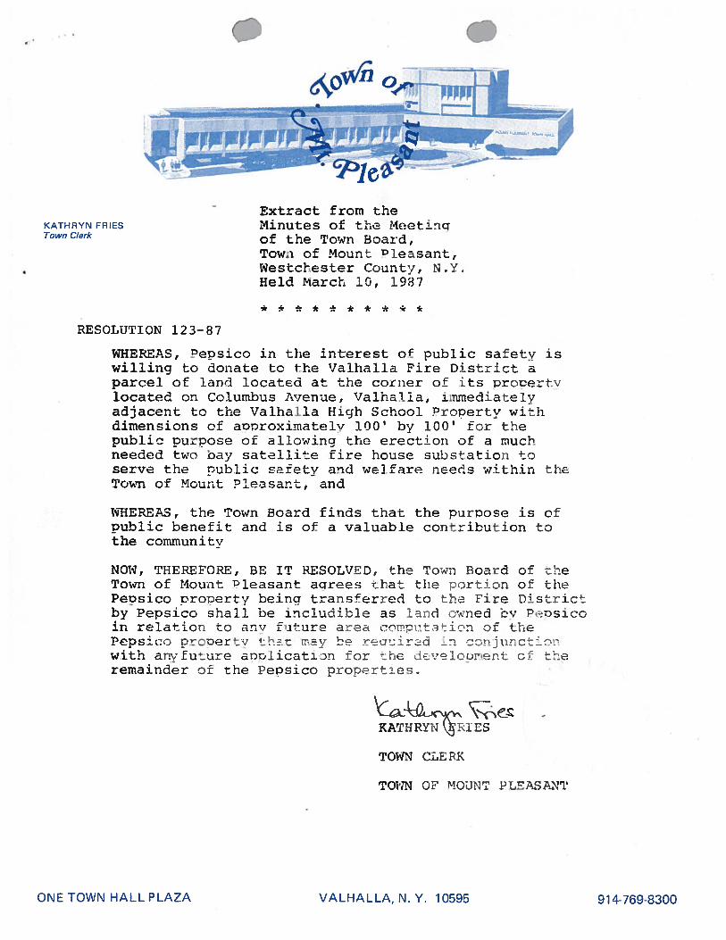
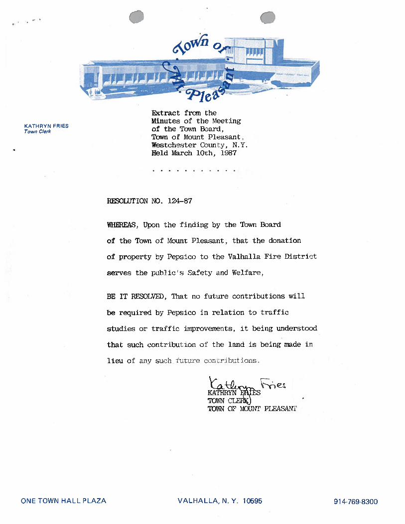
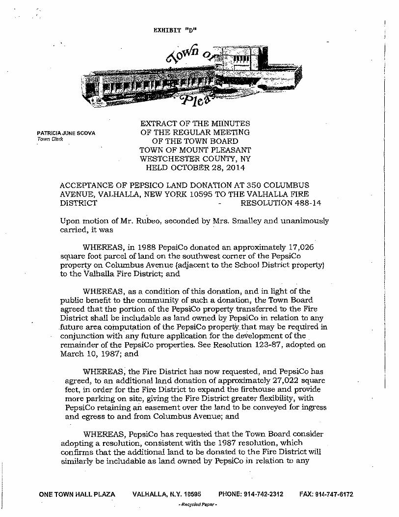
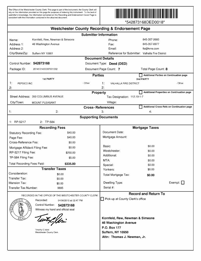
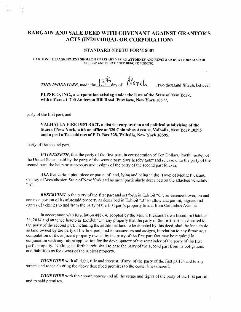
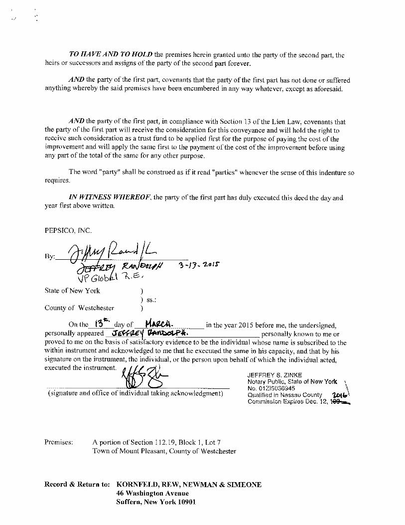
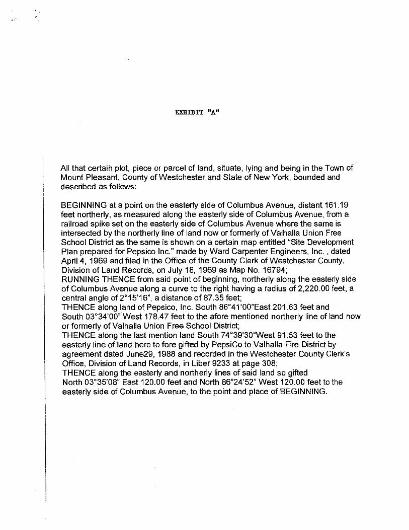
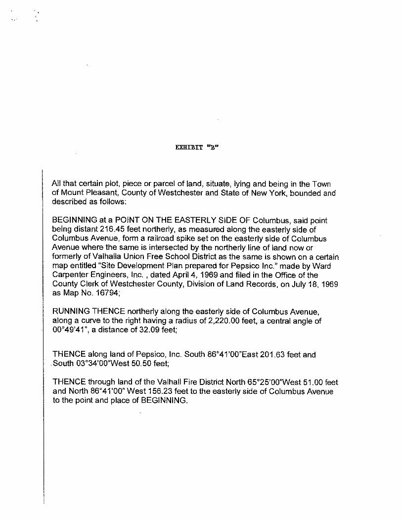
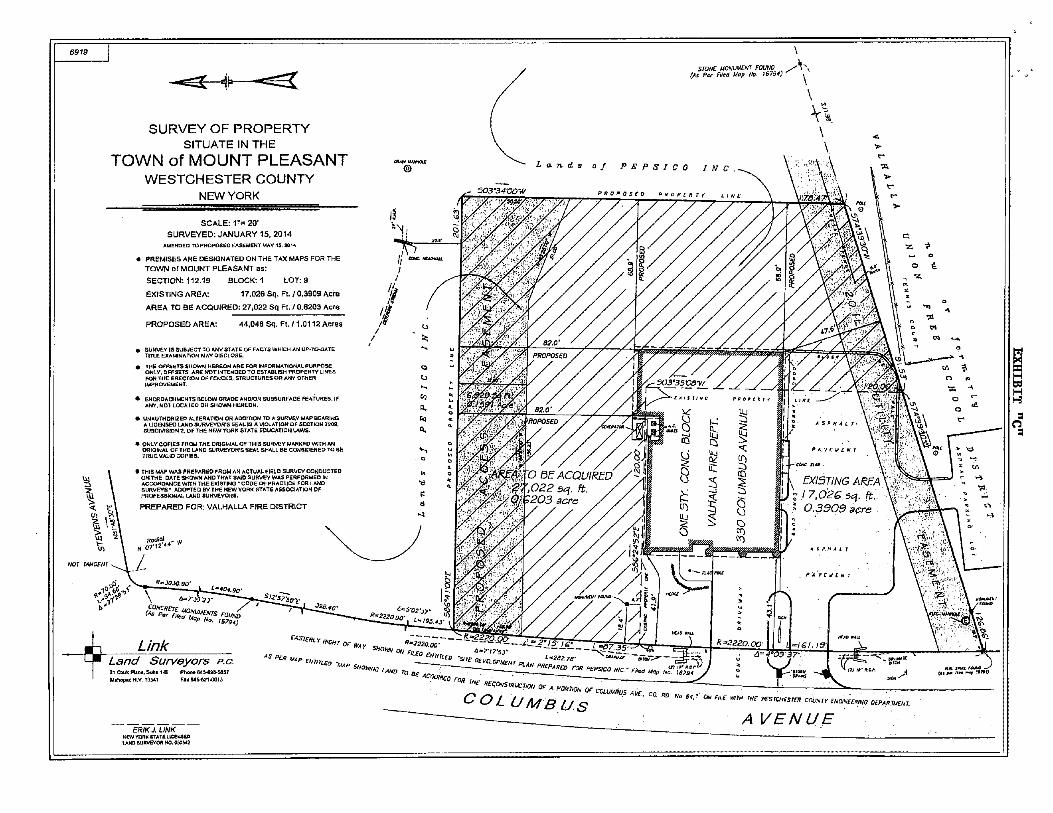
Related Documents