Pentti Häkkinen ER auxiliaries 9.1 Wärtsilä New Professionals 3.- 7.11.2008 Machinery Auxiliary Systems Contents and Targets Supplementary to Project Guide. Presentation focuses on system part in excess of engine system diagrams. Target is presentation of real systems and their components in ships. Many auxiliary systems are not dependent on engine power or transmission mode (electric - mechanical) Most are more dependent on number of main engines and number of main engine compartments Redundant engine rooms should be based on reliability and maintainability analysis Simple is beautiful! This is valid for all

Pentti Häkkinen ER auxiliaries 9.1 Wärtsilä New Professionals 3.-7.11.2008 Machinery Auxiliary Systems Contents and Targets Supplementary to Project Guide.
Dec 16, 2015
Welcome message from author
This document is posted to help you gain knowledge. Please leave a comment to let me know what you think about it! Share it to your friends and learn new things together.
Transcript
Pentti Häkkinen ER auxiliaries 9.1Wärtsilä New Professionals 3.-7.11.2008
Machinery Auxiliary Systems
Contents and Targets
Supplementary to Project Guide. Presentation focuses on system part in excess of engine system diagrams.
Target is presentation of real systems and their components in ships.
Many auxiliary systems are not dependent on engine power or transmission mode (electric - mechanical)
Most are more dependent on number of main engines and number of main engine compartments
Redundant engine rooms should be based on reliability and maintainability analysis
Simple is beautiful! This is valid for all systems.
Pentti Häkkinen ER auxiliaries 9.1Wärtsilä New Professionals 3.-7.11.2008
Fuel Oil Systems
HFO treatment plant in ship now receives ample attention. It hardly depends on fuel quality.
Fuel fed to engine must be
• homogenous
• clean of particles
• in correct viscosity
• in correct pressure
• ample circulation flow
This requires proper systems for
• bunkering,
• storage,
• transfer,
• purifying,
• feeding
Every stage consists of potential hazards, both in system design and ship operation
Pentti Häkkinen ER auxiliaries 9.1Wärtsilä New Professionals 3.-7.11.2008
Fuel Oil Bunkering
Bunkering place depends on price and quality. Extra fuel is carried onboard for one or two roundtrips.
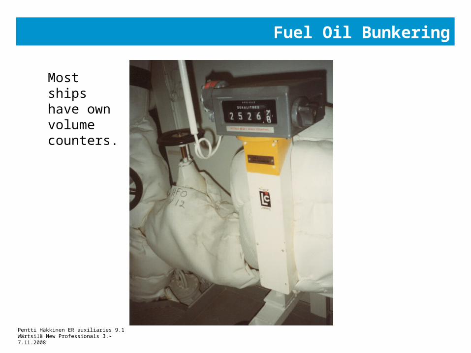
Bunkering stations on both sides. Capacity to receive 100 … 1000 m3/h. Most ships have own volume counters.
Standardised flanges for HFO and MDO to prevent errors.
Gravity filling when delivered to shipside.
Station is arranged so, that fuel entering in overflow pipe is immediately detected.
Fuel related problems are well-known. Most owners utilise analysing services: Sample dripped into sealed bottles. New fuel is kept separate to avoid compatibility problems.
Pentti Häkkinen ER auxiliaries 9.1Wärtsilä New Professionals 3.-7.11.2008
Fuel Oil Bunkering
Most ships have own volume counters.
Pentti Häkkinen ER auxiliaries 9.1Wärtsilä New Professionals 3.-7.11.2008
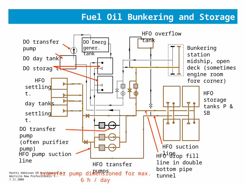
Fuel Oil Bunkering and Storage
HFO overflow tank
Bunkering station midship, open deck (sometimes engine room fore corner)
HFO storage tanks P & SB
HFO suction line
HFO drop fill line in double bottom pipe tunnel
HFO pump suction line
HFO transfer pumps
DO transfer pump(often purifier pump)
HFO settling t.
day tanks
settling t.
DO transfer pump
DO day tank
DO storag t.
DO Emerggener. tank
transfer pump dimensioned for max. 6 h / day
Pentti Häkkinen ER auxiliaries 9.1Wärtsilä New Professionals 3.-7.11.2008
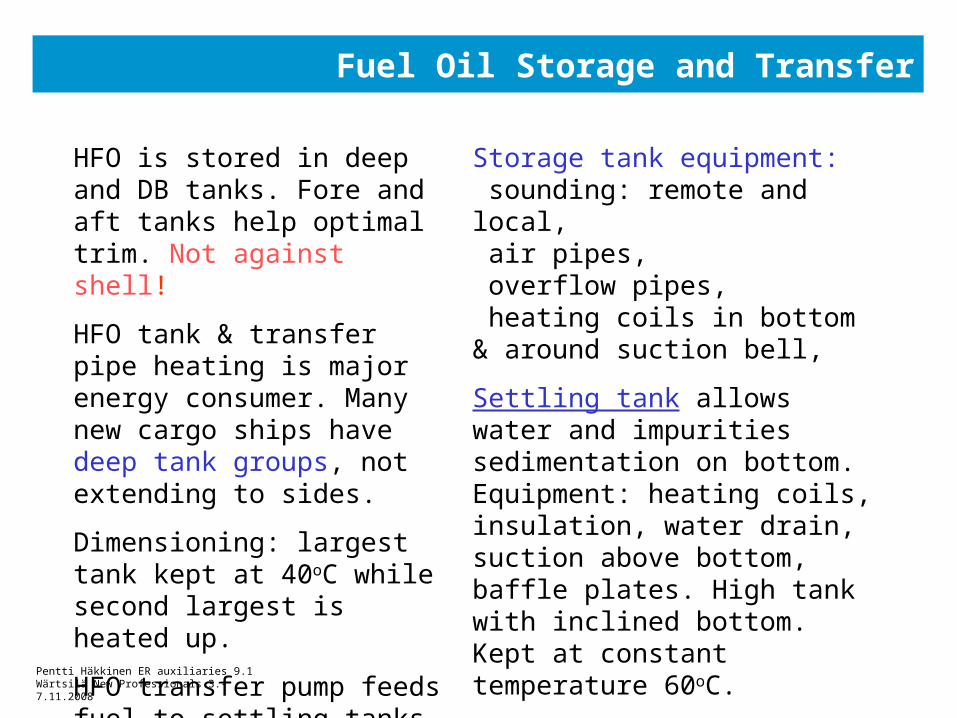
Fuel Oil Storage and Transfer
HFO is stored in deep and DB tanks. Fore and aft tanks help optimal trim. Not against shell!
HFO tank & transfer pipe heating is major energy consumer. Many new cargo ships have deep tank groups, not extending to sides.
Dimensioning: largest tank kept at 40oC while second largest is heated up.
HFO transfer pump feeds fuel to settling tanks. Two tanks for safety and flexibility.
Storage tank equipment: sounding: remote and local, air pipes, overflow pipes, heating coils in bottom & around suction bell,
Settling tank allows water and impurities sedimentation on bottom. Equipment: heating coils, insulation, water drain, suction above bottom, baffle plates. High tank with inclined bottom. Kept at constant temperature 60oC.
Pentti Häkkinen ER auxiliaries 9.1Wärtsilä New Professionals 3.-7.11.2008
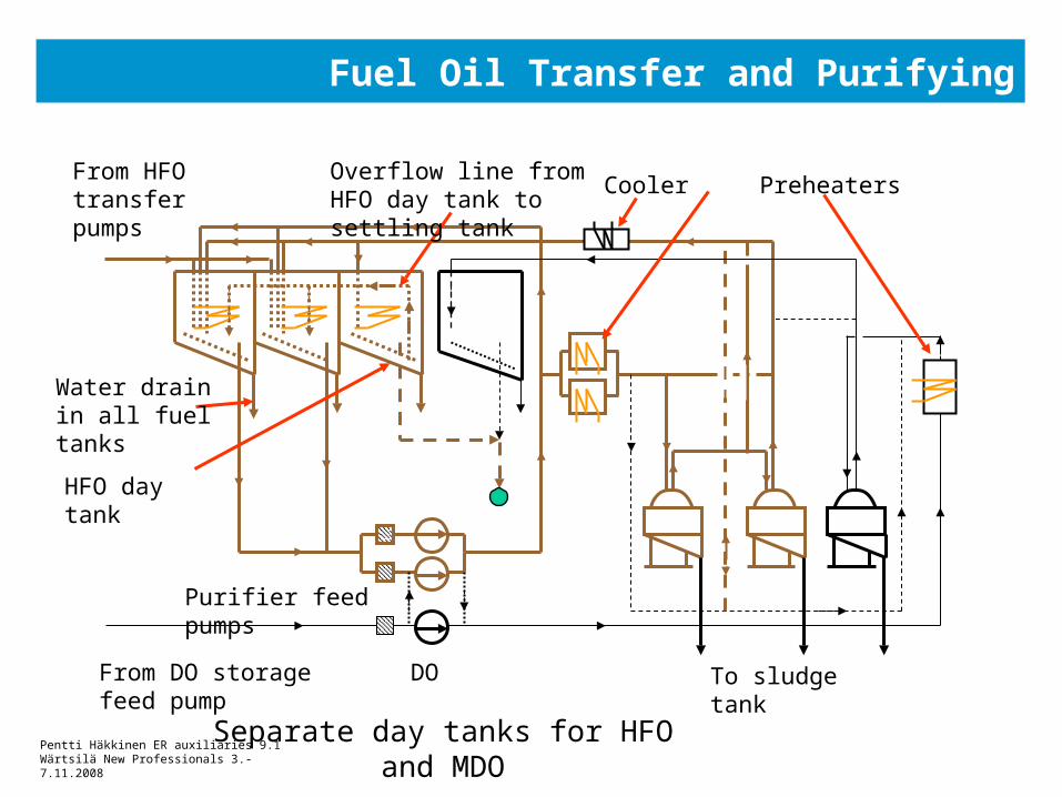
Fuel Oil Transfer and Purifying
Overflow line from HFO day tank to settling tank
Water drain in all fuel tanks
HFO day tank
Purifier feed pumps
Cooler Preheaters
To sludge tank From DO storage DO feed pump
From HFO transfer pumps
Separate day tanks for HFO and MDO
Pentti Häkkinen ER auxiliaries 9.1Wärtsilä New Professionals 3.-7.11.2008
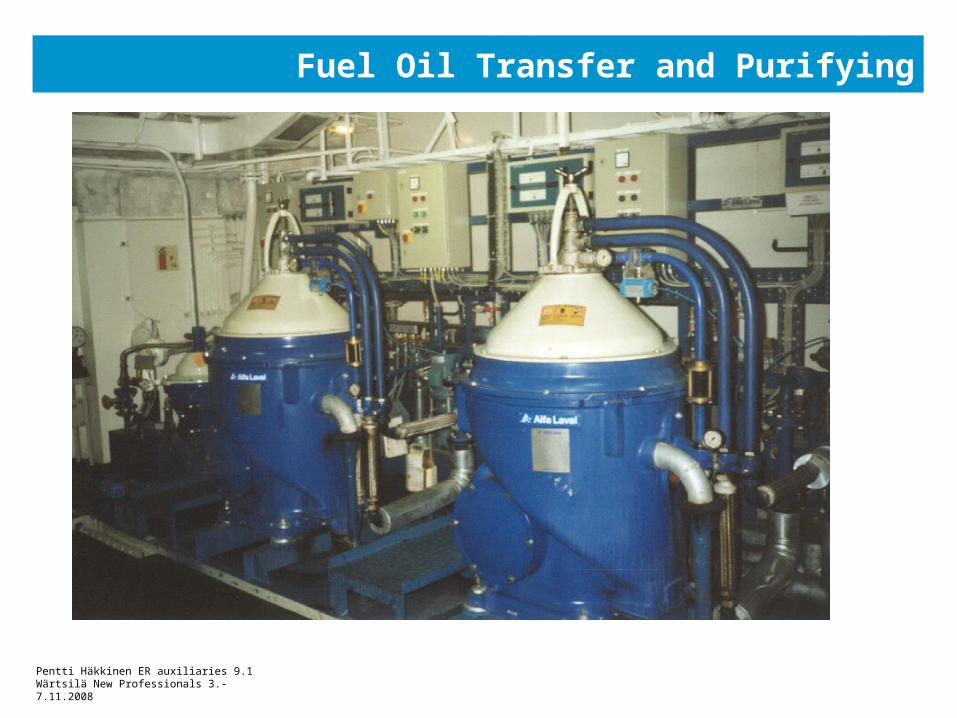
Fuel Oil Transfer and Purifying
Pentti Häkkinen ER auxiliaries 9.1Wärtsilä New Professionals 3.-7.11.2008
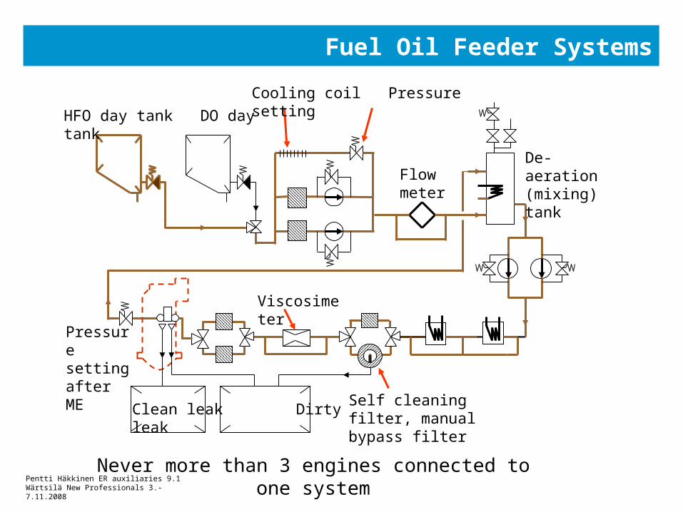
Fuel Oil Feeder Systems
HFO day tank DO day tank
Cooling coil Pressure setting
De-aeration (mixing) tankFlow
meter
Viscosimeter
Pressure setting after ME
Self cleaning filter, manual bypass filter
Clean leak Dirty leak
Never more than 3 engines connected to one system
Pentti Häkkinen ER auxiliaries 9.1Wärtsilä New Professionals 3.-7.11.2008
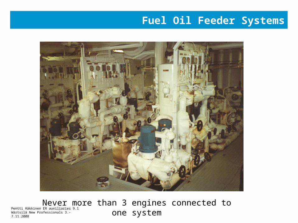
Fuel Oil Feeder Systems
Never more than 3 engines connected to one system
Pentti Häkkinen ER auxiliaries 9.1Wärtsilä New Professionals 3.-7.11.2008
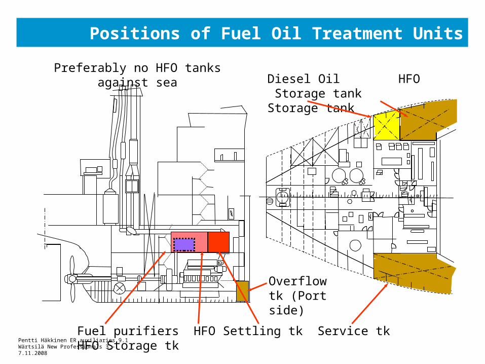
Positions of Fuel Oil Treatment Units
Diesel Oil HFO Storage tank Storage tank
Fuel purifiers HFO Settling tk Service tk HFO Storage tk
Overflow tk (Port side)
Preferably no HFO tanks against sea
Pentti Häkkinen ER auxiliaries 9.1Wärtsilä New Professionals 3.-7.11.2008
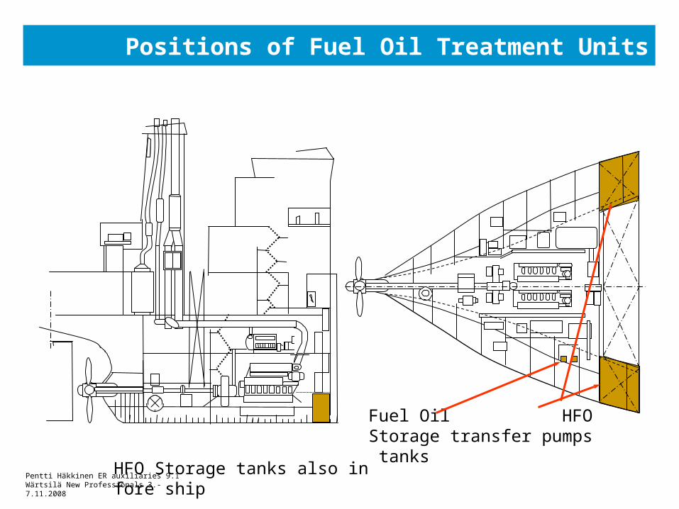
Positions of Fuel Oil Treatment Units
Fuel Oil HFO Storage transfer pumps tanks
HFO Storage tanks also in fore ship
Pentti Häkkinen ER auxiliaries 9.1Wärtsilä New Professionals 3.-7.11.2008
Fuel Oil Feeding Systems
Practical engine room designer topics
Only two engines fitted into one system
Location of booster module:
• ‘fuel corner’ is recommended, together with fuel purifiers
• rather high distance from engines accepted
• protected piping route! Not near walkways, delicate components nor areas where heavy loads are moved.
• module maintenance aspects. Insulated pipe is no footstep!
• plan a safe escape route in case of fire

Pentti Häkkinen ER auxiliaries 9.1Wärtsilä New Professionals 3.-7.11.2008
Fuel Oil Feeding Systems
Damping of pressure pulses• Injection pump causes short duration pulses
• Level 15 bar in common, even 80 bar measured
• Mild failures: pressure sensors, ..
• Serious failures: pipe ruptures
• Level is difficult to predict, level depends on many parameters
• IMO will set limit to 16 bar or double wall pipes required
• Many types of dampers are used
Pentti Häkkinen ER auxiliaries 9.1Wärtsilä New Professionals 3.-7.11.2008
Fuel Oil Feeding Systems
Common problems:•frequent filter clogging: incompatible fuel, small filters, purifier problems
•element cavitation caused by water or gas in fuel
•screw pump seizure as result of excessive recirculation
Fire hazard • MDO spray ignites immediately when hit on a hot (>150C) surface.
• HFO ignition almost equivalent
• Protective shielding around flange connections with leak monitoring
• Location of fuel lines, delicate and hot equipment
• Highest heat is directed above the flames
Pentti Häkkinen ER auxiliaries 9.1Wärtsilä New Professionals 3.-7.11.2008
Fuel Oil Equipment on Engine
Injection pumps and pipes are generally well encapsulated
Pressure control valve fitted on each engine
Supply and return pipes must tolerate constant movement of resiliently mounted engine
Leakage oil pipes (clean and dirty) monitored by level switch, trace heating needed
Engine driven fuel circulation pumps common, especially in auxiliary engines
Emergency operation secured with gravity MDO tank or pneumatic pump
Pentti Häkkinen ER auxiliaries 9.1Wärtsilä New Professionals 3.-7.11.2008
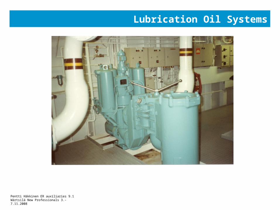
Lubrication Oil Systems
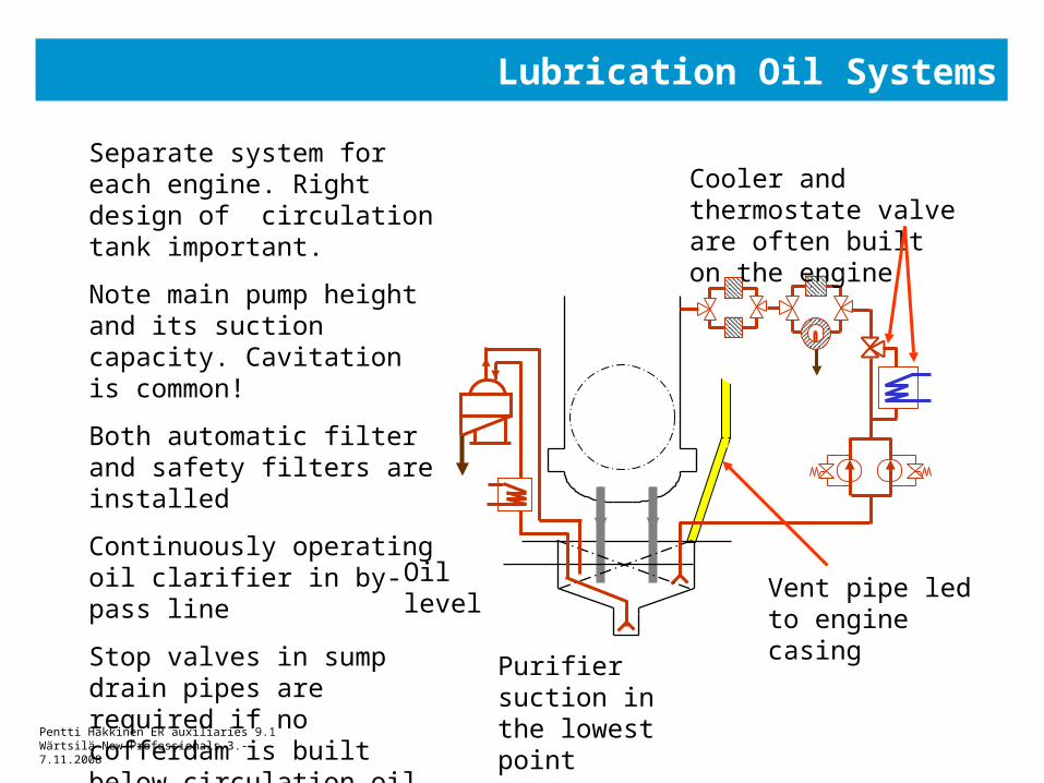
Separate system for each engine. Right design of circulation tank important.
Note main pump height and its suction capacity. Cavitation is common!
Both automatic filter and safety filters are installed
Continuously operating oil clarifier in by-pass line
Stop valves in sump drain pipes are required if no cofferdam is built below circulation oil tank. They prevent water entering in engine and machinery space.
Cooler and thermostate valve are often built on the engine
Purifier suction in the lowest point
Vent pipe led to engine casing
Oil level
Pentti Häkkinen ER auxiliaries 9.1Wärtsilä New Professionals 3.-7.11.2008
Lubrication Oil Systems
Engine driven pumps are preferred if several main engines. Electrically driven priming pump, its capacity depends on duty.
Two full size electrically driven pumps are standard for single engine ships
Emergency lubrication arrangement needed in special cases (when no disconnection clutch). Gravity tank or pneumatically driven pump
Stop valves in sump drain pipes are required if no cofferdam is built below circulation oil tank
Flexible pipe joints in case of resiliently mounted engine
Pentti Häkkinen ER auxiliaries 9.1Wärtsilä New Professionals 3.-7.11.2008
Lubrication Oil Systems
Pentti Häkkinen ER auxiliaries 9.1Wärtsilä New Professionals 3.-7.11.2008
CP Propeller Lubrication Oil Systems
CP-propeller oil system is integrated for pitch control, cooling and lubrication of mechanisms.
Separate from any other oil system. Typically two electrically driven pumps, filters and coolers assembled on top of storage tank.
Emergency lubrication arrangement needed in special cases.
Monitoring of water content and metal debris in oil is important. Contaminated oil lot is replaced. Can also be purified with centrifuge unit.
Pentti Häkkinen ER auxiliaries 9.1Wärtsilä New Professionals 3.-7.11.2008
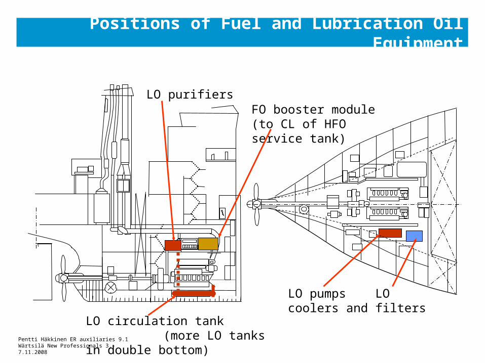
Positions of Fuel and Lubrication Oil Equipment
LO circulation tank (more LO tanks in double bottom)
LO pumps LO coolers and filters
FO booster module (to CL of HFO service tank)
LO purifiers
Pentti Häkkinen ER auxiliaries 9.1Wärtsilä New Professionals 3.-7.11.2008
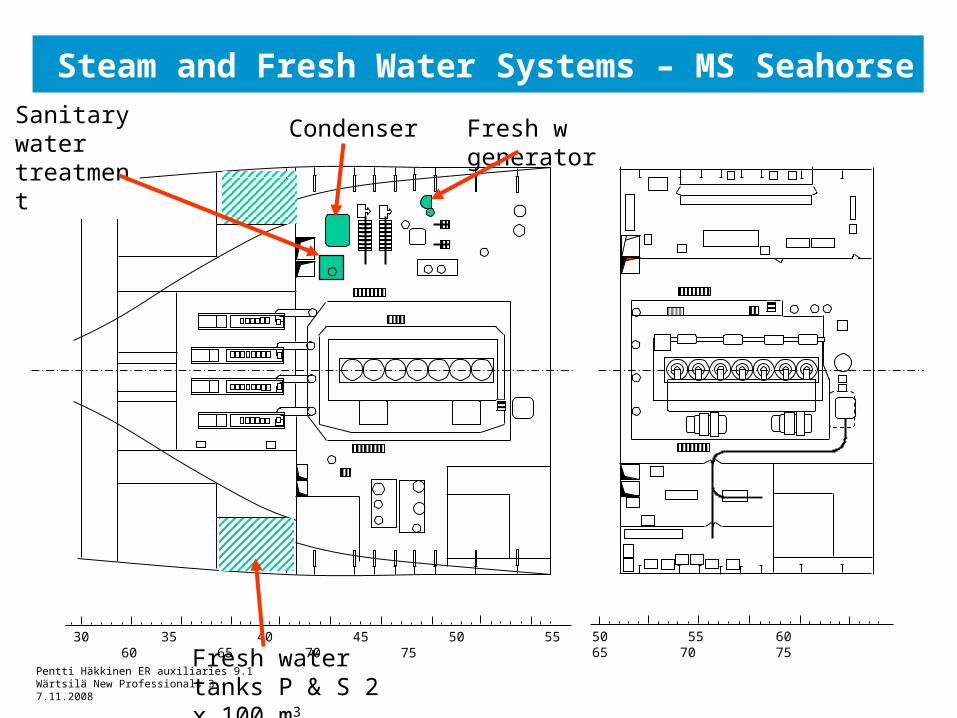
Steam and Fresh Water Systems – MS Seahorse
30 35 40 45 50 55 60 65 70 75 50 55 60 65 70 75
Fresh w generatorCondenserSanitary water treatment
Fresh water tanks P & S 2 x 100 m3
Pentti Häkkinen ER auxiliaries 9.1Wärtsilä New Professionals 3.-7.11.2008
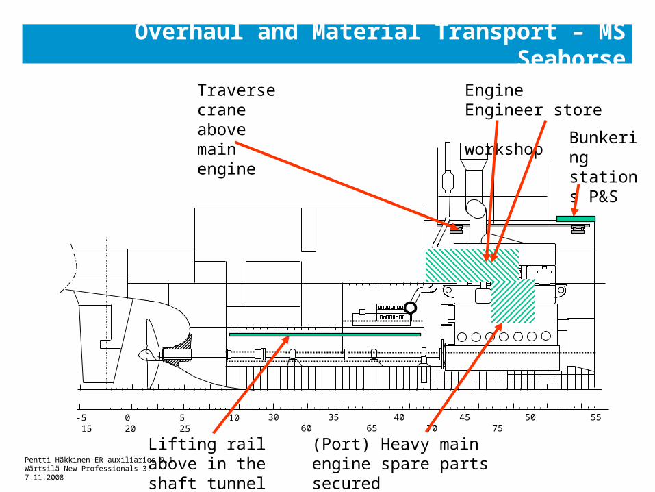
Overhaul and Material Transport – MS Seahorse
Traverse crane above main engine
Engine Engineer store workshop
(Port) Heavy main engine spare parts secured
30 35 40 45 50 55 60 65 70 75-5 0 5 10 15 20 25
Bunkering stations P&S
Lifting rail above in the shaft tunnel
Pentti Häkkinen ER auxiliaries 9.1Wärtsilä New Professionals 3.-7.11.2008
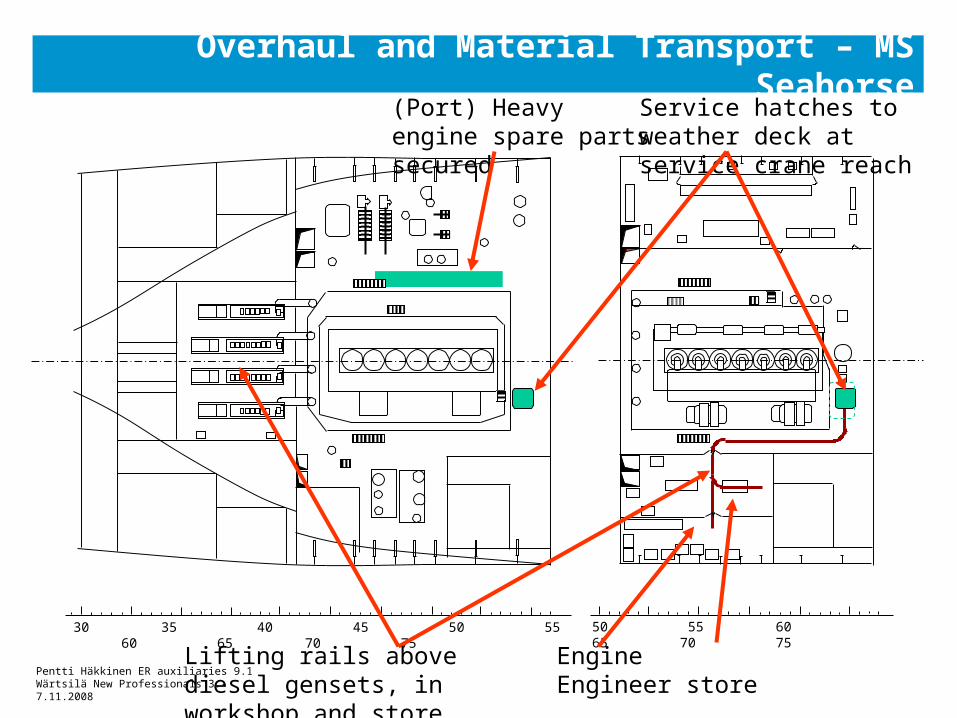
(Port) Heavy engine spare parts secured
Overhaul and Material Transport – MS Seahorse
Engine Engineer store workshop
30 35 40 45 50 55 60 65 70 75 50 55 60 65 70 75
Lifting rails above diesel gensets, in workshop and store
Service hatches to weather deck at service crane reach
Pentti Häkkinen ER auxiliaries 9.1Wärtsilä New Professionals 3.-7.11.2008
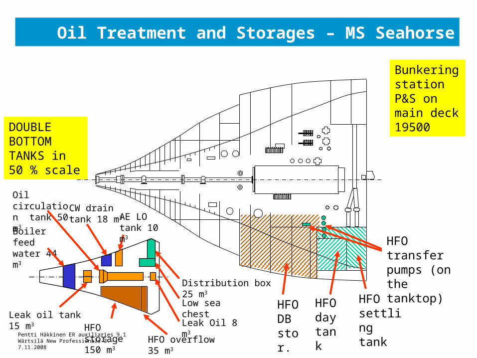
Oil Treatment and Storages – MS Seahorse
Bunkering station P&S on main deck 19500
HFO settling tank
HFO transfer pumps (on the tanktop)
Boiler feed water 44 m3
Leak oil tank 15 m3
Oil circulation tank 50 m3 CW drain
tank 18 m3 AE LO tank 10 m3
Distribution box 25 m3
Low sea chest
HFO overflow 35 m3
Leak Oil 8 m3
HFO day tankHFO storage
150 m3
DOUBLE BOTTOM TANKS in 50 % scale
HFO DB stor.
Pentti Häkkinen ER auxiliaries 9.1Wärtsilä New Professionals 3.-7.11.2008
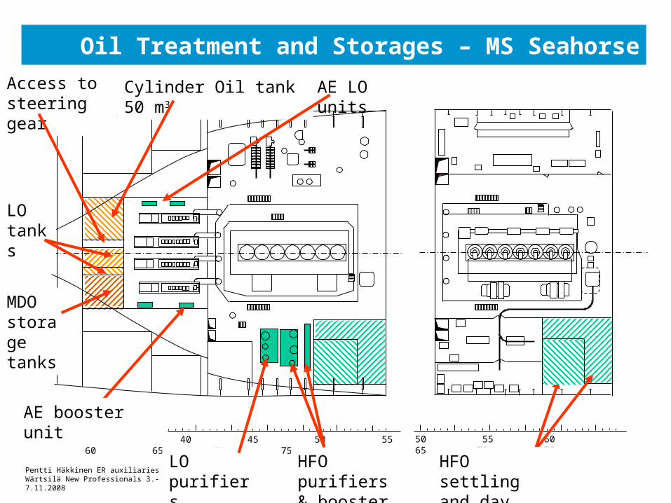
Oil Treatment and Storages – MS Seahorse
30 35 40 45 50 55 60 65 70 75 50 55 60 65 70 75
HFO settling and day tanks
HFO purifiers & booster unit
AE booster unit
MDO storage tanks
LO tanks
LO purifiers
Cylinder Oil tank 50 m3Access to steering gear
AE LO units
Pentti Häkkinen ER auxiliaries 9.1Wärtsilä New Professionals 3.-7.11.2008
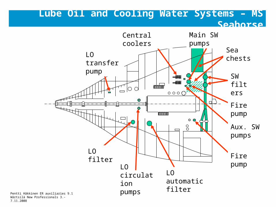
Lube Oil and Cooling Water Systems – MS Seahorse
LO circulation pumps
Central coolers
LO transfer pump
LO filter
Main SW pumps
SW filters
LO automatic filter
Fire pump
Aux. SW pumps
Fire pump
Sea chests
Related Documents