Pellet boiler englisch BIOCOM Installation instructions BC-A-00-00-00-01-IAEN EN-B31-007-V10-0711

Welcome message from author
This document is posted to help you gain knowledge. Please leave a comment to let me know what you think about it! Share it to your friends and learn new things together.
Transcript
Pellet boiler englisch
BIOCOM
Installation instructions BC-A-00-00-00-01-IAEN
EN-B31-007-V10-0711
BIOCOM Installation Instructions
2
Information on this documentation BS-B-00-00-00-01-IAEN
Please read through this documentation carefully.
It is intended as a reference document and contains important information on the design, safety, operation, maintenance and care of your heating system.
We are always looking to improve our products and documentation. Any ideas and suggestions you may have will be gratefully received.
GUNTAMATIC Heiztechnik GmbH a Georg Fischer Group Company
Bruck 7
A-4722 PEUERBACH
Tel: 0043 (0) 7276 / 2441-0
Fax: 0043 (0) 7276 / 3031
E-mail: [email protected]
It is important that you pay particular attention to the safety issues highlighted in the text by these symbols.
The entire contents of this document are the property of GUNTAMATIC and therefore protected by copyright. Reproduction of any kind, communication to third parties by any means or use for purposes other than those intended without the written consent of the owner is prohibited.
Subject to printing errors and technical amendments.
BIOCOM Installation Instructions
3
Installation instructions BC-C-00-00-00-01-IAEN Page 1 Introduction..........................................................4
1.1 Safety instructions 4 1.2 Guarantee 4 1.3 Commissioning 4 1.4 Site requirements 4 1.4.1 Fire safety (minimum fire safety requirements) 5 1.4.2 Boiler room requirements 7 1.4.3 Flue requirements 8 1.4.4 Fuel store requirements 9
2 Installation and assembly .................................11 2.1 Delivery 11 2.2 Carrying to installation site 11 2.3 Positioning and aligning the boiler 11 2.4 Plumbing connections 12 2.5 Filling and bleeding the system 15 2.6 Connecting the flue 16 2.7 Energy saving draught regulator with pressure-surge
compensator 17 2.8 Installing the fuel outfeed system 18 2.8.1 FLEX system 18 2.8.2 BOX system 21
3 Electrical connections.......................................22 3.1 Electrical connections to the heating system 22 3.2 Wiring requirements 23 3.3 Electrical connections 24
4 Final checks/Commissioning............................27
5 Standards/Regulations......................................28
6 Plumbing diagrams...................................... 29-45
7 Electrical wiring diagram ..................................46 7.1 Control panel 46 7.2 Wall controller set MK261 47 7.3 Boiler circuit board 48
8 Technical data....................................................49 8.1 BIOCOM 30-100 49-50 8.2 FLEX outfeed system 51 8.3 BOX outfeed system 51
BIOCOM Installation Instructions
4
1 Introduction BS-01-00-00-00-01-IAEN
1.1 Safety instructions BS-01-01-00-00-01-IAEN
GUNTAMATIC heating systems represent state-of-the-art technology and meet all applicable safety regulations. Incorrect installation can endanger life and limb. Heating boilers are combustion systems and are potentially dangerous if handled incorrectly. Installation, commissioning and servicing must, therefore, only be carried out by adequately qualified technicians observing all regulations and the manufacturer's instructions.
1.2 Guarantee and warranty BS-01-02-00-00-01-IAEN
The manufacturer's guarantee is subject to correct installation and commissioning of the heating system. Defects and damage caused by incorrect installation, commissioning or operation are not covered by the guarantee. To ensure that the system functions as intended, the manufacturer's instructions must be followed. Furthermore, only genuine replacement parts or parts explicitly approved by the manufacturer may be fitted to the system.
1.3 Commissioning BS-01-03-00-00-01-IAEN
Commissioning of the boiler must be carried out by an authorised GUNTAMATIC specialist or other qualified persons. They will check whether the system has been installed according to the plans, adjust the system settings as required and explain to the system operator how to use the heating system.
1.4 Site requirements BS-01-04-00-00-01-IAEN
When establishing the site requirements, it is absolutely essential to take account of the locally applicable planning, building and implementation regulations and the dimensional specifications in the fitting guidelines, installation examples and technical data. Compliance with the locally applicable regulations and the correct implementation of the measures required on site are solely the responsibility of the system owner and are a requirement of the manufacturer's guarantee. GUNTAMATIC provides no guarantee of any kind for any type of site work. Without making any claims as to completeness or non-applicability of official requirements, we recommend the following specifications based on the Austrian Guidelines pr TRVB H 118:
BIOCOM Installation Instructions
5
1.4.1 Fire safety BS-01-04-01-00-01-IAEN
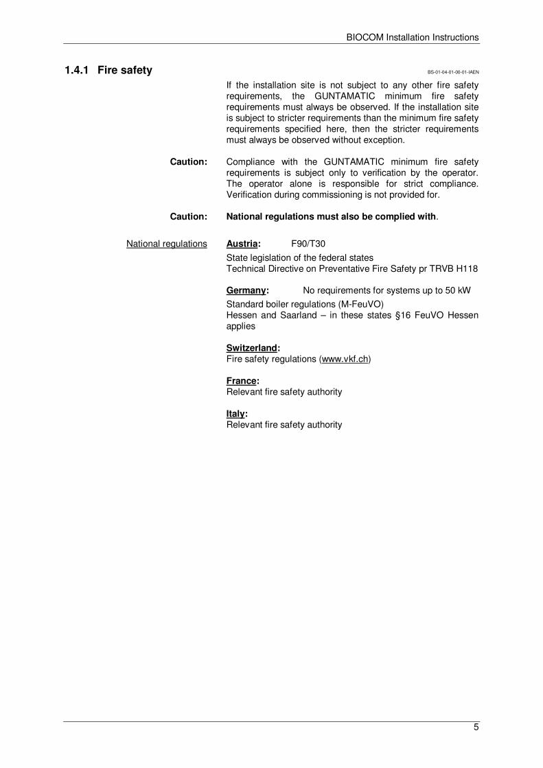
If the installation site is not subject to any other fire safety requirements, the GUNTAMATIC minimum fire safety requirements must always be observed. If the installation site is subject to stricter requirements than the minimum fire safety requirements specified here, then the stricter requirements must always be observed without exception.
Caution: Compliance with the GUNTAMATIC minimum fire safety requirements is subject only to verification by the operator. The operator alone is responsible for strict compliance. Verification during commissioning is not provided for.
Caution: National regulations must also be complied with.
National regulations Austria: F90/T30
State legislation of the federal states Technical Directive on Preventative Fire Safety pr TRVB H118
Germany: No requirements for systems up to 50 kW
Standard boiler regulations (M-FeuVO) Hessen and Saarland – in these states §16 FeuVO Hessen applies
Switzerland: Fire safety regulations (www.vkf.ch)
France: Relevant fire safety authority
Italy: Relevant fire safety authority
BIOCOM Installation Instructions
6
Minimum fire safety requirements BS-01-04-01-01-01-IAEN
BS-01-04-01-02-01-IAEN
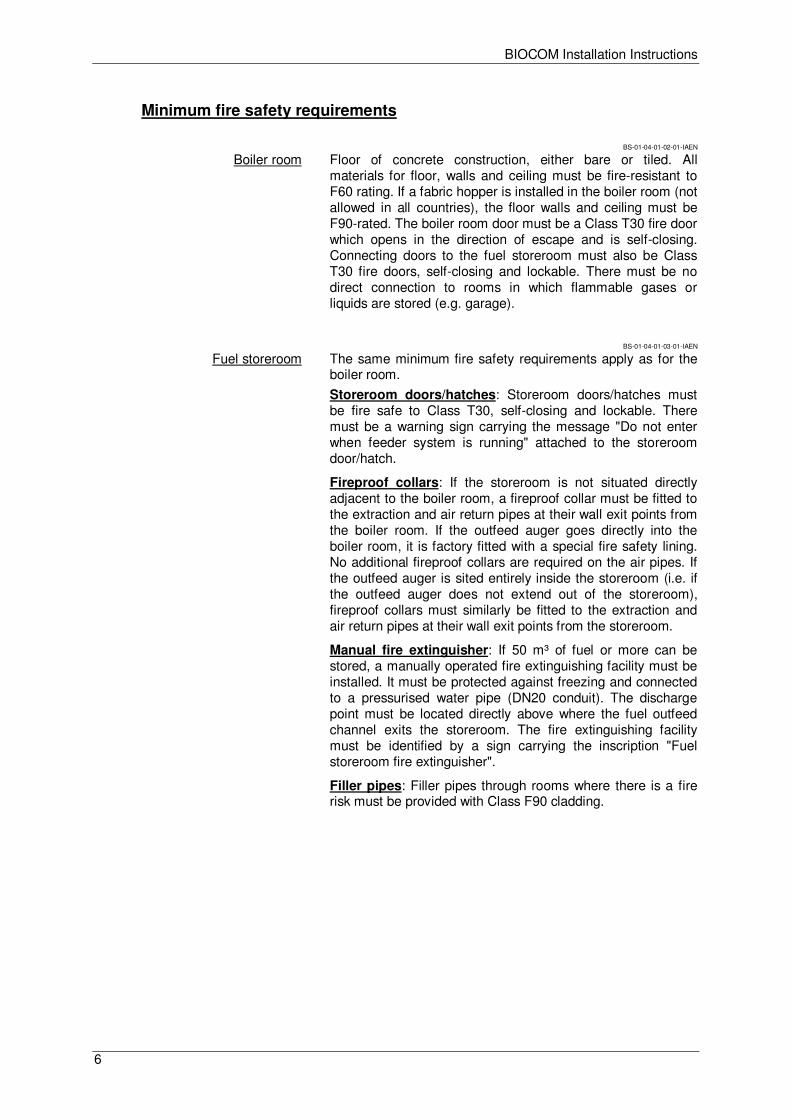
Boiler room Floor of concrete construction, either bare or tiled. All materials for floor, walls and ceiling must be fire-resistant to F60 rating. If a fabric hopper is installed in the boiler room (not allowed in all countries), the floor walls and ceiling must be F90-rated. The boiler room door must be a Class T30 fire door which opens in the direction of escape and is self-closing. Connecting doors to the fuel storeroom must also be Class T30 fire doors, self-closing and lockable. There must be no direct connection to rooms in which flammable gases or liquids are stored (e.g. garage).
BS-01-04-01-03-01-IAEN
Fuel storeroom The same minimum fire safety requirements apply as for the boiler room.
Storeroom doors/hatches: Storeroom doors/hatches must be fire safe to Class T30, self-closing and lockable. There must be a warning sign carrying the message "Do not enter when feeder system is running" attached to the storeroom door/hatch.
Fireproof collars: If the storeroom is not situated directly adjacent to the boiler room, a fireproof collar must be fitted to the extraction and air return pipes at their wall exit points from the boiler room. If the outfeed auger goes directly into the boiler room, it is factory fitted with a special fire safety lining. No additional fireproof collars are required on the air pipes. If the outfeed auger is sited entirely inside the storeroom (i.e. if the outfeed auger does not extend out of the storeroom), fireproof collars must similarly be fitted to the extraction and air return pipes at their wall exit points from the storeroom.
Manual fire extinguisher: If 50 m³ of fuel or more can be stored, a manually operated fire extinguishing facility must be installed. It must be protected against freezing and connected to a pressurised water pipe (DN20 conduit). The discharge point must be located directly above where the fuel outfeed channel exits the storeroom. The fire extinguishing facility must be identified by a sign carrying the inscription "Fuel storeroom fire extinguisher".
Filler pipes: Filler pipes through rooms where there is a fire risk must be provided with Class F90 cladding.
BIOCOM Installation Instructions
7
1.4.2 Boiler room requirements BS-01-04-02-00-01-IAEN
PH-01-04-02-01-01-IAEN
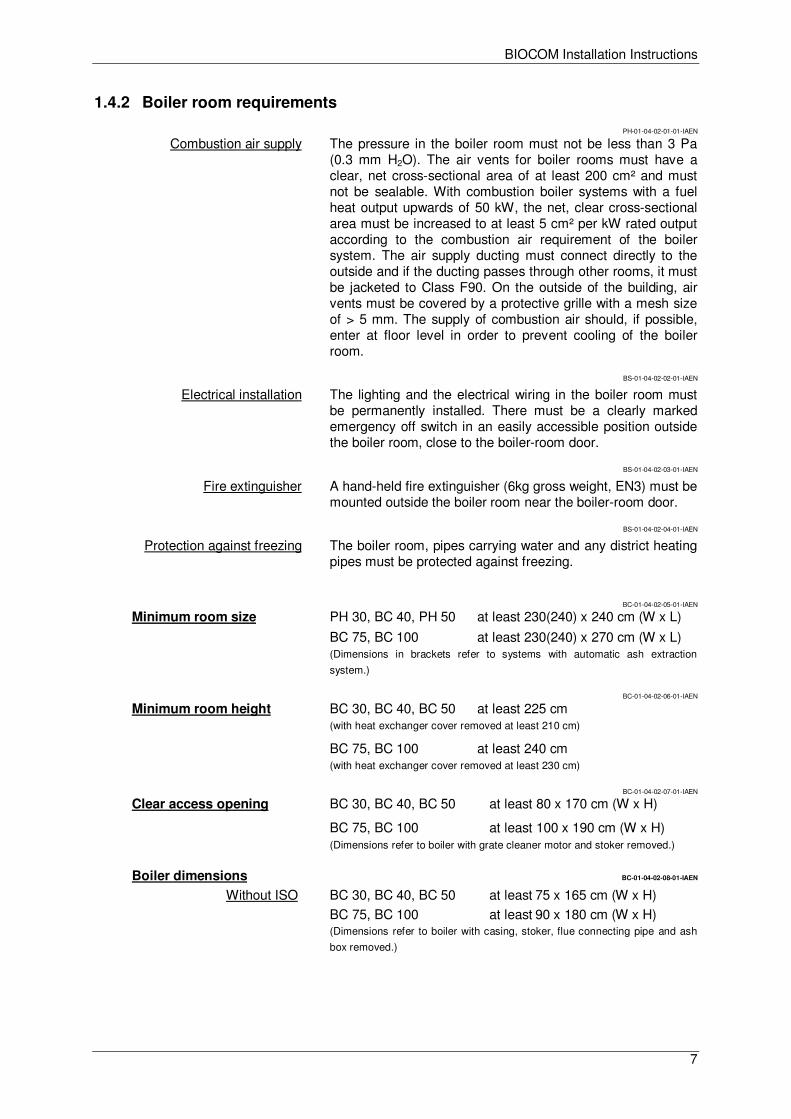
Combustion air supply The pressure in the boiler room must not be less than 3 Pa (0.3 mm H2O). The air vents for boiler rooms must have a clear, net cross-sectional area of at least 200 cm² and must not be sealable. With combustion boiler systems with a fuel heat output upwards of 50 kW, the net, clear cross-sectional area must be increased to at least 5 cm² per kW rated output according to the combustion air requirement of the boiler system. The air supply ducting must connect directly to the outside and if the ducting passes through other rooms, it must be jacketed to Class F90. On the outside of the building, air vents must be covered by a protective grille with a mesh size of > 5 mm. The supply of combustion air should, if possible, enter at floor level in order to prevent cooling of the boiler room.
BS-01-04-02-02-01-IAEN
Electrical installation The lighting and the electrical wiring in the boiler room must be permanently installed. There must be a clearly marked emergency off switch in an easily accessible position outside the boiler room, close to the boiler-room door.
BS-01-04-02-03-01-IAEN
Fire extinguisher A hand-held fire extinguisher (6kg gross weight, EN3) must be mounted outside the boiler room near the boiler-room door.
BS-01-04-02-04-01-IAEN
Protection against freezing The boiler room, pipes carrying water and any district heating pipes must be protected against freezing.
BC-01-04-02-05-01-IAEN
Minimum room size PH 30, BC 40, PH 50 at least 230(240) x 240 cm (W x L)
BC 75, BC 100 at least 230(240) x 270 cm (W x L) (Dimensions in brackets refer to systems with automatic ash extraction
system.)
BC-01-04-02-06-01-IAEN
Minimum room height BC 30, BC 40, BC 50 at least 225 cm (with heat exchanger cover removed at least 210 cm)
BC 75, BC 100 at least 240 cm (with heat exchanger cover removed at least 230 cm)
BC-01-04-02-07-01-IAEN
Clear access opening BC 30, BC 40, BC 50 at least 80 x 170 cm (W x H)
BC 75, BC 100 at least 100 x 190 cm (W x H) (Dimensions refer to boiler with grate cleaner motor and stoker removed.)
Boiler dimensions BC-01-04-02-08-01-IAEN
Without ISO BC 30, BC 40, BC 50 at least 75 x 165 cm (W x H)
BC 75, BC 100 at least 90 x 180 cm (W x H) (Dimensions refer to boiler with casing, stoker, flue connecting pipe and ash
box removed.)
BIOCOM Installation Instructions
8
1.4.3 Flue requirements BS-01-04-03-00-01-IAEN
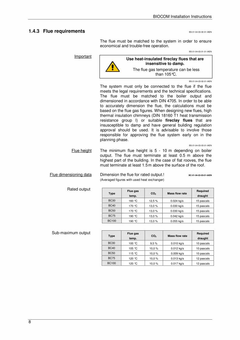
The flue must be matched to the system in order to ensure economical and trouble-free operation.
BS-01-04-03-01-01-IAEN
Important
BS-01-04-03-02-01-IAEN
The system must only be connected to the flue if the flue meets the legal requirements and the technical specifications. The flue must be matched to the boiler output and dimensioned in accordance with DIN 4705. In order to be able to accurately dimension the flue, the calculations must be based on the flue gas figures. When designing new flues, high thermal insulation chimneys (DIN 18160 T1 heat transmission resistance group I) or suitable fireclay flues that are insusceptible to damp and have general building regulation approval should be used. It is advisable to involve those responsible for approving the flue system early on in the planning phase.
BS-01-04-03-03-01-IAEN
Flue height The minimum flue height is 5 - 10 m depending on boiler output. The flue must terminate at least 0.5 m above the highest part of the building. In the case of flat rooves, the flue must terminate at least 1.5 m above the surface of the roof.
Flue dimensioning data Dimension the flue for rated output.! BC-01-04-03-05-01-IAEN
(Averaged figures with used heat exchanger)
Rated output
Sub-maximum output
Type Flue gas
temp. CO2 Mass flow rate
Required
draught
BC30 160 °C 12,5 % 0.024 kg/s 15 pascals
BC40 170 °C 13,0 % 0.030 kg/s 15 pascals
BC50 170 °C 13,0 % 0.030 kg/s 15 pascals
BC75 190 °C 13,0 % 0.042 kg/s 15 pascals
BC100 190 °C 13,0 % 0.055 kg/s 15 pascals
Type Flue gas
temp. CO2 Mass flow rate
Required
draught
BC30 100 °C 9,5 % 0.010 kg/s 10 pascals
BC40 105 °C 10,0 % 0.012 kg/s 10 pascals
BC50 115 °C 10,0 % 0.009 kg/s 10 pascals
BC75 120 °C 10,0 % 0.013 kg/s 12 pascals
BC100 120 °C 10,0 % 0.017 kg/s 12 pascals
Use heat-insulated fireclay flues that are insensitive to damp.
The flue gas temperature can be less than 105°C.
BIOCOM Installation Instructions
9
1.4.4 Fuel store requirements BS-01-04-04-00-01-IAEN
BS-01-04-04-01-01-IAEN
Access doors/hatches Above-ground fuel stores must be provided with a door or hatch that opens outwards. So that the fuel cannot run out if the fuel store is opened by mistake, the inside of the access door/hatch opening must be covered with boarding (which must be removable from the outside). Due to the risk of injury when the system is in operation, access doors/hatches must be lockable and kept locked when the system is in operation. There must be a warning sign carrying the message "Do not enter when feeder system is running" attached to the access door/hatch.
Electrical equipment FLEX system BS-01-04-04-02-01-IAEN
Electrical equipment is prohibited in the fuel storeroom.
BOX system
Electrical equipment is permitted in the room in which the system is installed. Light bulbs must not be fitted in close proximity to the fabric hopper.
BS-01-04-04-03-01-IAEN
Filler set The filler pipes must be earthed.
FLEX system
At least 2 filler pipes must be installed. Minimum separation 0.5 m.
BS-01-04-04-04-01-IAEN
Installation in cold areas If installed in cold areas, vacuum pipes and outfeed unit must be adequately insulated (frost-proof).
Risk of condensation formation
Structural requirements FLEX system BS-01-04-04-05-01-IAEN
The enclosing walls must be capable of withstanding the possible static loads created by the fuel and the pressure when filling the fuel store.
BOX system
It is imperative that the load-bearing capacity of the base is adequately dimensioned as, when the hopper is completely full, heavy loads act on the points on which the unit rests.
BS-01-04-04-06-01-IAEN
Erecting BOX system Indoor installation: The fabric hopper must always be installed separately from the boiler in a different room. In some countries, the fabric hopper may be installed in the same room as the boiler if a minimum separation of 1 m between the fabric hopper and the boiler can be maintained and the fuel heat output remains below 50 kW.
National legislation must also be observed!
Outdoor installation: If erected outdoors, no F90 lining is required if the minimum distances for fire flashover are maintained. The fabric hopper must be protected against rain, damp and UV light.
BIOCOM Installation Instructions
10
BS-01-04-04-07-01-IAEN
Wall penetration If there is an auger conveyor passing through the storeroom wall, the gap in the wall must be filled with mineral wool and sealed by means of the non-contact (sound insulation) finishing plates provided.
BS-01-04-04-08-01-IAEN
Filling the fuel store When pressure-filling the fuel store from a tanker truck, the air pumped in must be drawn out of the fuel store. Extraction is the responsibility of the supplier.
BS-01-04-04-09-01-IAEN
Damp-proofing The fuel must be protected against contact with water or damp floors/walls. The storeroom must remain dry all year round. If there is a risk of temporarily damp walls, fitting a back-ventilated facing to the walls and lining them with wooden material may be required.
BIOCOM Installation Instructions
11
2 Installation and assembly BS-02-00-00-00-01-IAEN
2.1 Delivery BS-02-01-00-00-01-IAEN
The boiler system is delivered packed in a wooden crate wrapped in foil. Please check that the delivery is complete according to the delivery note and in perfect condition.
Deficiencies Please make a note of the deficiencies identified directly on the delivery note and contact the supplier, heating installer or our Customer Service.
2.2 Carrying to installation site BS-02-02-00-00-01-IAEN
The system is delivered on a wooden pallet and can be lifted and carried to the installation site using a pallet truck.
Carrying in dismantled The boiler body can be dismantled into parts for carrying in. If that is done, a person authorised by GUNTAMATIC must be consulted.
2.3 Positioning and aligning the boiler PH-02-03-00-00-01-IAEN
Keep to the minimum wall clearances specified by the system planner and manufacturer. If important details are missing, please refer to the planning documentation or ask our Technical Support. Position the system as close as possible to the flue to avoid having a long flue connecting pipe. The system must be accessible from the left or right side.
Clearance on left at least 40 cm (preferably 70 cm)
Clearance on right at least 40 cm
Clearance at front at least 80 cm (leave space for fuel box door to open)
Clearance at back at least 50 cm (with auto ash extraction system, at least 60 cm)
Floor clearance Set the clearance between the boiler base and the floor to the required minimum of 35 mm by unscrewing the adjustable feet on the boiler base.
Set the boiler at a slant Unscrew the rear adjustable feet slightly further so that the boiler is slightly higher at the rear. That will allow the air inside the boiler to escape easily when the system is filled.
BIOCOM Installation Instructions
12
2.4 Plumbing connections BC-02-04-00-00-01-IAEN
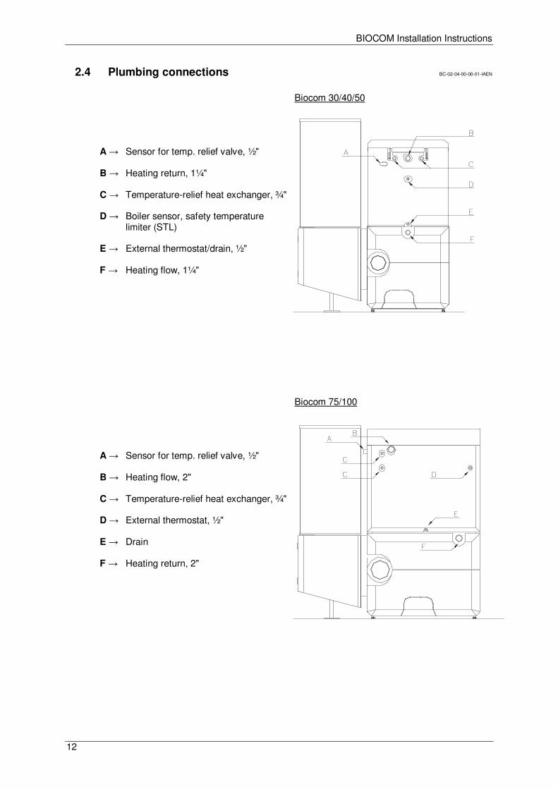
Biocom 30/40/50
A → Sensor for temp. relief valve, ½"
B → Heating return, 1¼"
C → Temperature-relief heat exchanger, ¾"
D → Boiler sensor, safety temperature limiter (STL)
E → External thermostat/drain, ½"
F → Heating flow, 1¼"
Biocom 75/100
A → Sensor for temp. relief valve, ½"
B → Heating flow, 2"
C → Temperature-relief heat exchanger, ¾"
D → External thermostat, ½"
E → Drain
F → Heating return, 2"
BIOCOM Installation Instructions
13
BC-02-04-00-01-01-IAEN
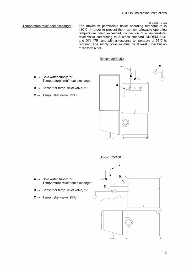
Temperature-relief heat exchanger The maximum permissible boiler operating temperature is 110°C. In order to prevent the maximum allowable operating temperature being exceeded, connection of a temperature-relief valve conforming to Austrian standard ÖNORM 8131 and DIN 4751 and with a response temperature of 95°C is required. The supply pressure must be at least 2 bar but no more than 6 bar.
Biocom 30/40/50
A → Cold water supply for Temperature-relief heat exchanger
B → Sensor for temp. relief valve, ½"
C → Temp. relief valve, 95°C
Biocom 75/100
A → Cold water supply for Temperature-relief heat exchanger
B → Sensor for temp. relief valve, ½"
C → Temp. relief valve, 95°C
BIOCOM Installation Instructions
14
PH-02-04-00-02-01-IAEN
Thermal store Installing a thermal store is not necessary as the boiler is operated by a modulating control system and the system can be quickly shut down. However, if the required continuous heat output in the summer months is below 10 kW for systems up to 50 kW, or 22 kW for systems upwards of 50 kW, combination with a thermal store is necessary for reasons of efficiency.
BC-02-04-00-03-01-IAEN
Return boost The boiler return temperature must be at least 40°C in systems up to 50 kW and 45°C for systems upwards of 50 kW, and must be held at the required level by a bypass pump between the boiler flow and return pipes. If a thermal store is connected, the boiler return temperature must be at least 55 °C, which must be ensured by a return boost set as shown in the plumbing diagram. If this requirement is not complied with, there is an increased risk of corrosion and guarantee entitlement will be lost as a result. Connect the return boost set precisely as specified in our plumbing diagrams.
Important The dimensioning of the return boost pump (set) is designed for the arrangements shown in GUNTAMATIC plumbing diagrams. If additional components such as heat meters are incorporated in the system plumbing, or if the overall thermal store pipe run (flow and return) is more than 30 m, re-dimensioning of the boiler charging pump (HP0) may be necessary.
SY-02-04-00-04-01-IAEN
Expansion vessel The boiler operates in a sealed heating system and must be provided with an expansion vessel for pressure compensation. To calculate the expansion volume, the volume of the system when cold must be known. Please select the expansion vessel on the basis of the manufacturer's specifications. The expansion volume of the system is calculated as follows:
System volume x Expansion factor x Additional allowance factor • Expansion factor for wood-fuel boilers = 0.03 • Additional allowance factor = 3.0 for systems under 30 kW • Additional allowance factor = 2.0 for 30-150 kW systems • Additional allowance factor = 1.5 for systems over 150 kW
Example calculation: 2500 litres x 0.03 x 3 = 225 litres
BS-02-04-00-05-01-IAEN
Plastic piping If plastic piping for underfloor heating or district heating pipes are connected, they must be protected against excessive temperatures by using a limiting thermostat for the circulation pumps.
BS-02-04-00-06-01-IAEN
Pump selection The choice of pump must be made by the installer or building technology planner on the basis of the friction data, the pipe cross-sectional area and the required delivery pressure for the piping system planned.
BIOCOM Installation Instructions
15
2.5 Filling and bleeding the system BS-02-05-00-00-01-IAEN
The system is filled with water from the domestic supply. Please note the guidelines on "Corrosion and boiler protection in heating and domestic water systems".
Water quality The water quality of hot water systems with flow temperatures of max. 100°C is subject to VDI 2035. According to VDI 2035 Part 1, "Avoiding damage to hot water systems", which comply with EN12828, the first-fill and replenishment water, must be conditioned (preferably softened) if the following overall hardness limits [°dH] according to total heat output (kW) are exceeded:
• < 50kW: with circulating flow heaters, if °dH > 16.8
• 50 to 200 kW: if °dH > 11.2
• 200 to 500 kW: if °dH > 8.4
• > 500kW: if °dH > 0.11
Water heater If a water heater is also used in addition to the GUNTAMATIC boiler, it should be filled according to the installation instructions for it.
Filling the system
• Match the pressure of the system when cold to the air charge pressure of the expansion vessel
• Check the operating pressure on the pressure gauge
Bleeding the system
• Switch off and bleed circulation pumps.
• Bleed boiler by opening the bleed valve on the boiler and allowing air to escape until water runs out.
• Bleed radiator heating system (if present) by opening the bleed valve on every radiator and allowing air to escape until water runs out.
• Bleed underfloor heating system (if present) by opening each heating circuit and flushing through thoroughly until there are no more air bubbles in the heating circuit pipes.
• Important: perform sequence in the correct order! Start bleeding in the cellar or on the ground floor and finish in the attic.
• Check the system operating pressure on the pressure gauge and add more water if necessary.
• Restart circulation pumps.
Only systems that have been properly bled guarantee effective conveyance of heat.
BIOCOM Installation Instructions
16
2.6 Connecting the flue BS-02-06-00-00-01-IAEN
BC-02-06-00-01-01-IAEN
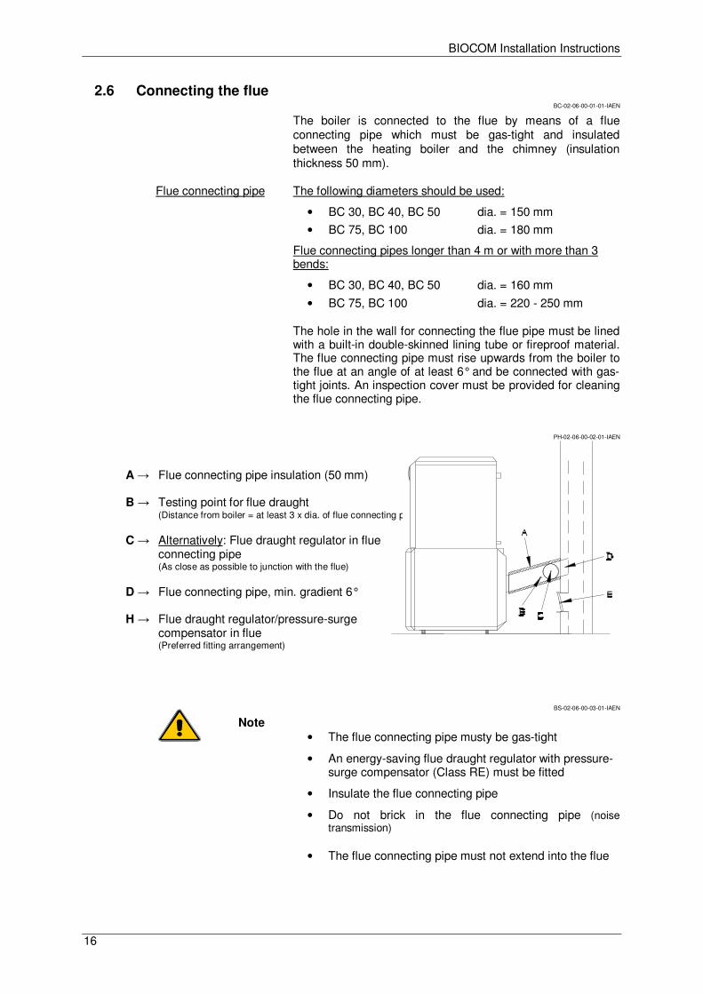
The boiler is connected to the flue by means of a flue connecting pipe which must be gas-tight and insulated between the heating boiler and the chimney (insulation thickness 50 mm).
Flue connecting pipe The following diameters should be used:
• BC 30, BC 40, BC 50 dia. = 150 mm
• BC 75, BC 100 dia. = 180 mm
Flue connecting pipes longer than 4 m or with more than 3 bends:
• BC 30, BC 40, BC 50 dia. = 160 mm
• BC 75, BC 100 dia. = 220 - 250 mm
The hole in the wall for connecting the flue pipe must be lined with a built-in double-skinned lining tube or fireproof material. The flue connecting pipe must rise upwards from the boiler to the flue at an angle of at least 6° and be connected with gas-tight joints. An inspection cover must be provided for cleaning the flue connecting pipe.
PH-02-06-00-02-01-IAEN
A → Flue connecting pipe insulation (50 mm) B → Testing point for flue draught
(Distance from boiler = at least 3 x dia. of flue connecting pipe) C → Alternatively: Flue draught regulator in flue
connecting pipe (As close as possible to junction with the flue)
D → Flue connecting pipe, min. gradient 6° H → Flue draught regulator/pressure-surge
compensator in flue (Preferred fitting arrangement)
BS-02-06-00-03-01-IAEN
Note • The flue connecting pipe musty be gas-tight
• An energy-saving flue draught regulator with pressure-surge compensator (Class RE) must be fitted
• Insulate the flue connecting pipe
• Do not brick in the flue connecting pipe (noise transmission)
• The flue connecting pipe must not extend into the flue
BIOCOM Installation Instructions
17
2.7 Energy-saving flue draught regulator and pressure-surge compensator
BS-02-07-00-00-01-IAEN
Purpose
• To ventilate the flue when the system is not in operation
• To compensate for pressure surges
• To regulate and limit the flue draught
Fitting requirement The energy-saving flue draught regulator must be fitted in accordance with the local regulations, preferably in the flue approx. 0.5 m below the point where the flue connecting pipe joins or alternatively in the flue connecting pipe close to its junction with the flue.
Flue draught setting:
• Adjusting the flue draught is only of any use at outside temperatures below +5°C.
• The system must have been in operation for at least an hour
• Ensure there is sufficient demand for heat for the boiler to be run at rated output for at least 15 minutes
• Measure the flue draught between the boiler and the flue draught regulator (distance of measuring point from boiler ideally 3 x flue diameter from connection between boiler and flue connecting pipe).
Flue draught The flue draught should not differ by more than +/- 3 pascals from the figure specified in the flue dimensioning data. If the flue draught cannot be reduced to the required figure, either a larger draught regulator should be fitted or an additional flue baffle fitted between the flue and the draught regulator.
Too much flue draught May cause the flue gas temperature to increase and accelerate combustion as a result. Poor boiler output adjustability, increased dust discharge and malfunctions can result.
Too little flue draught Performance problems, incomplete combustion and malfunctions when operating below rated output can result.
Fitting an energy-saving flue draught regulator/pressure-surge compensator (Class
RE) is absolutely imperative.
BIOCOM Installation Instructions
18
2.8 Fuel outfeed installation BS-02-08-00-00-01-IAEN
2.8.1 FLEX system BS-02-08-01-00-01-IAEN
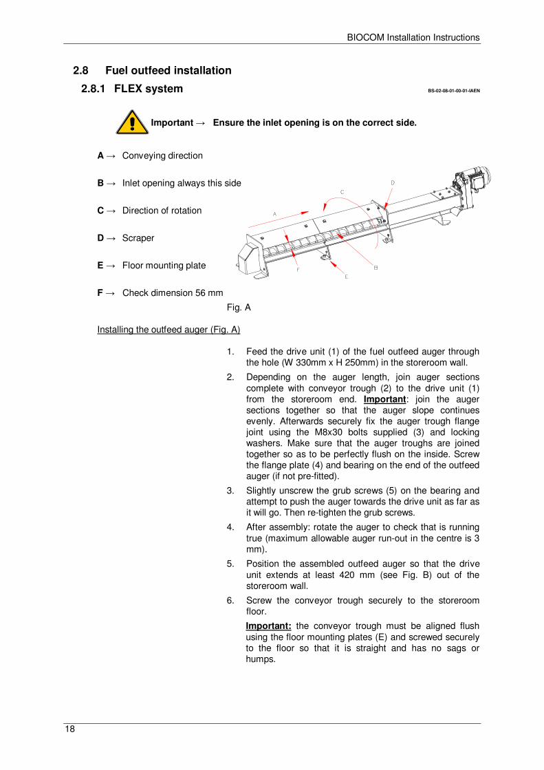
Important → Ensure the inlet opening is on the correct side.
A → Conveying direction
B → Inlet opening always this side
C → Direction of rotation
D → Scraper
E → Floor mounting plate
F → Check dimension 56 mm
Fig. A
Installing the outfeed auger (Fig. A)
1. Feed the drive unit (1) of the fuel outfeed auger through the hole (W 330mm x H 250mm) in the storeroom wall.
2. Depending on the auger length, join auger sections complete with conveyor trough (2) to the drive unit (1) from the storeroom end. Important: join the auger sections together so that the auger slope continues evenly. Afterwards securely fix the auger trough flange joint using the M8x30 bolts supplied (3) and locking washers. Make sure that the auger troughs are joined together so as to be perfectly flush on the inside. Screw the flange plate (4) and bearing on the end of the outfeed auger (if not pre-fitted).
3. Slightly unscrew the grub screws (5) on the bearing and attempt to push the auger towards the drive unit as far as it will go. Then re-tighten the grub screws.
4. After assembly: rotate the auger to check that is running true (maximum allowable auger run-out in the centre is 3 mm).
5. Position the assembled outfeed auger so that the drive unit extends at least 420 mm (see Fig. B) out of the storeroom wall.
6. Screw the conveyor trough securely to the storeroom floor.
Important: the conveyor trough must be aligned flush using the floor mounting plates (E) and screwed securely to the floor so that it is straight and has no sags or humps.
BIOCOM Installation Instructions
19
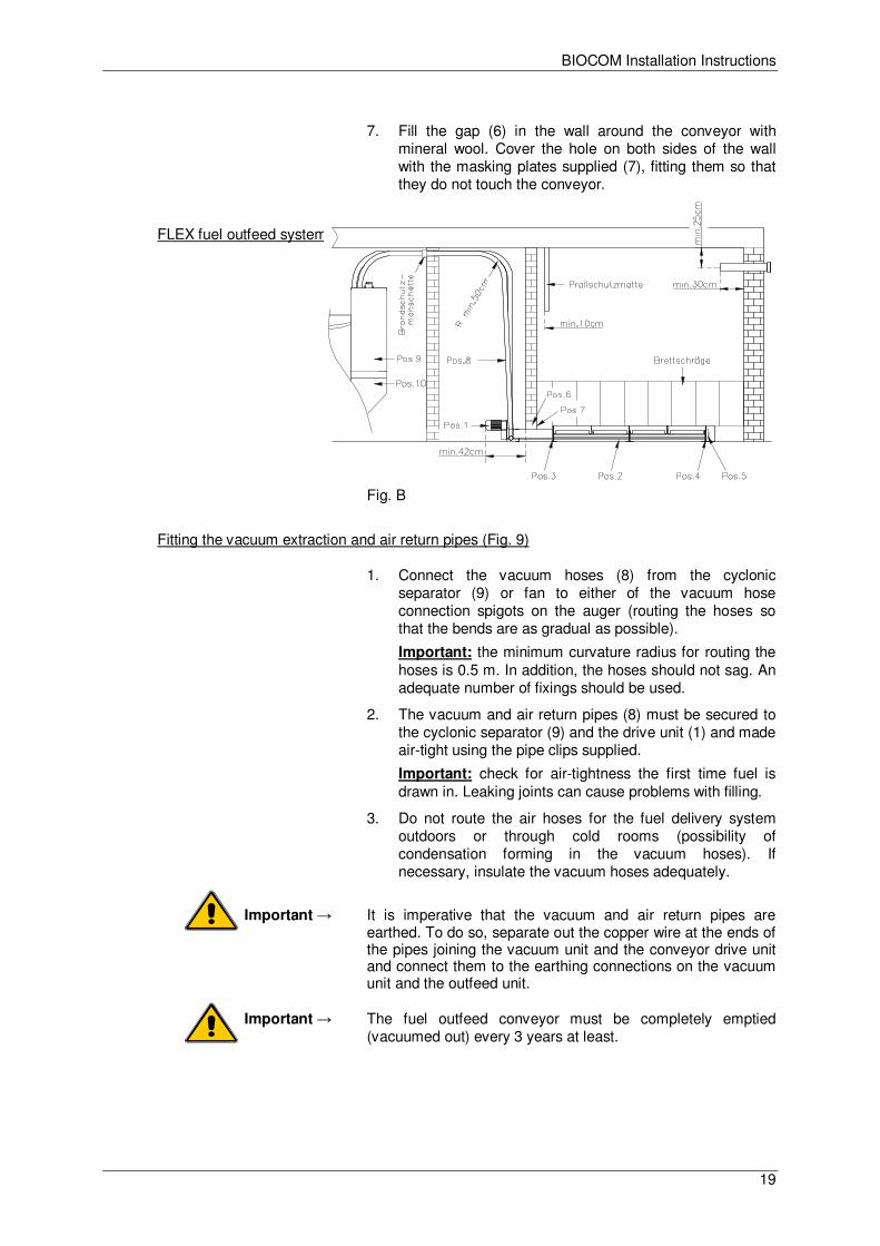
7. Fill the gap (6) in the wall around the conveyor with
mineral wool. Cover the hole on both sides of the wall with the masking plates supplied (7), fitting them so that they do not touch the conveyor.
FLEX fuel outfeed system
Fig. B
Fitting the vacuum extraction and air return pipes (Fig. 9)
1. Connect the vacuum hoses (8) from the cyclonic separator (9) or fan to either of the vacuum hose connection spigots on the auger (routing the hoses so that the bends are as gradual as possible).
Important: the minimum curvature radius for routing the hoses is 0.5 m. In addition, the hoses should not sag. An adequate number of fixings should be used.
2. The vacuum and air return pipes (8) must be secured to the cyclonic separator (9) and the drive unit (1) and made air-tight using the pipe clips supplied.
Important: check for air-tightness the first time fuel is drawn in. Leaking joints can cause problems with filling.
3. Do not route the air hoses for the fuel delivery system outdoors or through cold rooms (possibility of condensation forming in the vacuum hoses). If necessary, insulate the vacuum hoses adequately.
Important → It is imperative that the vacuum and air return pipes are earthed. To do so, separate out the copper wire at the ends of the pipes joining the vacuum unit and the conveyor drive unit and connect them to the earthing connections on the vacuum unit and the outfeed unit.
Important → The fuel outfeed conveyor must be completely emptied (vacuumed out) every 3 years at least.
BIOCOM Installation Instructions
20
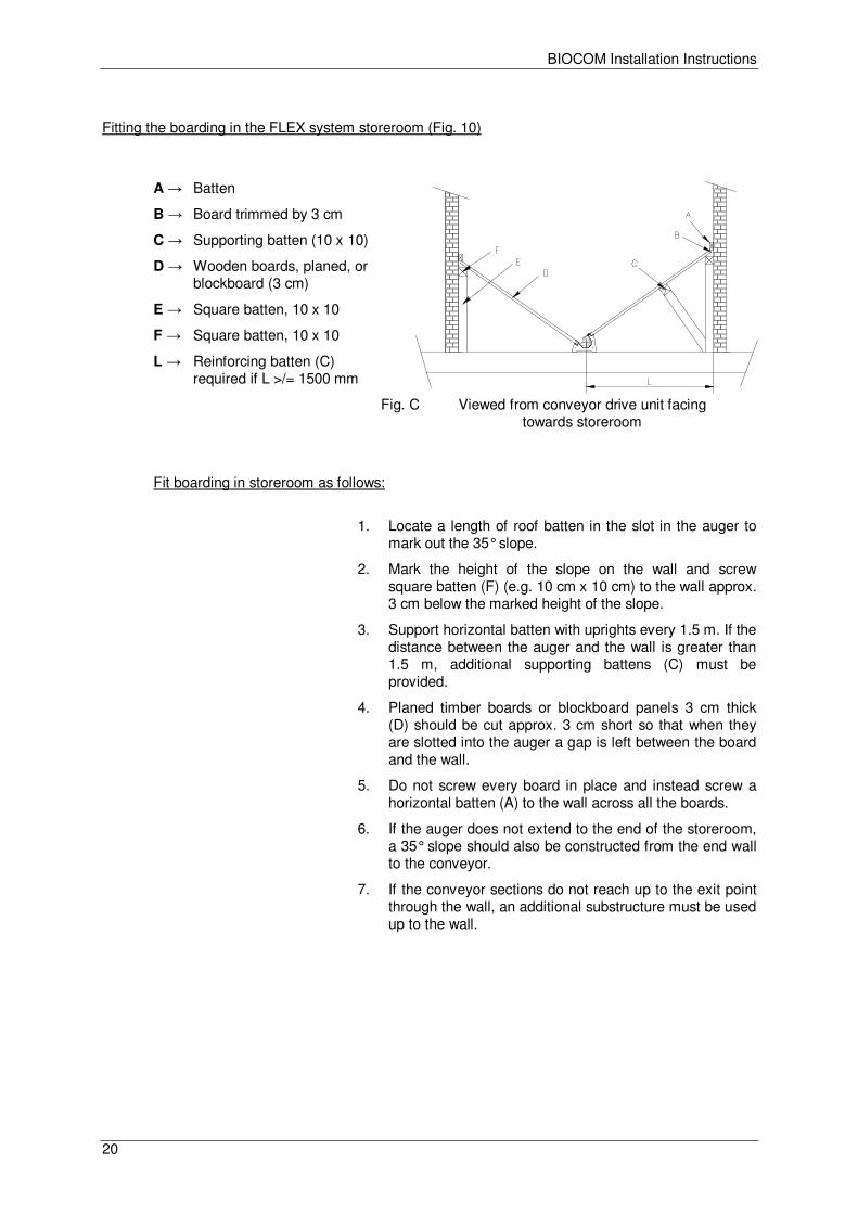
Fitting the boarding in the FLEX system storeroom (Fig. 10)
A → Batten
B → Board trimmed by 3 cm
C → Supporting batten (10 x 10)
D → Wooden boards, planed, or blockboard (3 cm)
E → Square batten, 10 x 10
F → Square batten, 10 x 10
L → Reinforcing batten (C) required if L >/= 1500 mm
Fig. C Viewed from conveyor drive unit facing towards storeroom
Fit boarding in storeroom as follows:
1. Locate a length of roof batten in the slot in the auger to mark out the 35° slope.
2. Mark the height of the slope on the wall and screw square batten (F) (e.g. 10 cm x 10 cm) to the wall approx. 3 cm below the marked height of the slope.
3. Support horizontal batten with uprights every 1.5 m. If the distance between the auger and the wall is greater than 1.5 m, additional supporting battens (C) must be provided.
4. Planed timber boards or blockboard panels 3 cm thick (D) should be cut approx. 3 cm short so that when they are slotted into the auger a gap is left between the board and the wall.
5. Do not screw every board in place and instead screw a horizontal batten (A) to the wall across all the boards.
6. If the auger does not extend to the end of the storeroom, a 35° slope should also be constructed from the end wall to the conveyor.
7. If the conveyor sections do not reach up to the exit point through the wall, an additional substructure must be used up to the wall.
BIOCOM Installation Instructions
21
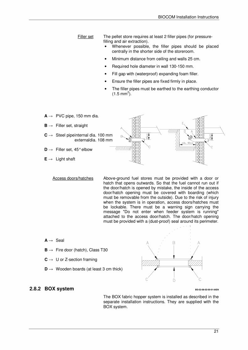
Filler set The pellet store requires at least 2 filler pipes (for pressure-
filling and air extraction). • Whenever possible, the filler pipes should be placed
centrally in the shorter side of the storeroom.
• Minimum distance from ceiling and walls 25 cm.
• Required hole diameter in wall 130-150 mm.
• Fill gap with (waterproof) expanding foam filler.
• Ensure the filler pipes are fixed firmly in place.
• The filler pipes must be earthed to the earthing conductor (1.5 mm2).
A → PVC pipe, 150 mm dia.
B → Filler set, straight
C → Steel pipe internal dia. 100 mm external dia. 108 mm
D → Filler set, 45° elbow
E → Light shaft
Access doors/hatches Above-ground fuel stores must be provided with a door or hatch that opens outwards. So that the fuel cannot run out if the door/hatch is opened by mistake, the inside of the access door/hatch opening must be covered with boarding (which must be removable from the outside). Due to the risk of injury when the system is in operation, access doors/hatches must be lockable. There must be a warning sign carrying the message "Do not enter when feeder system is running" attached to the access door/hatch. The door/hatch opening must be provided with a (dust-proof) seal around its perimeter.
A → Seal
B → Fire door (hatch), Class T30
C → U or Z-section framing
D → Wooden boards (at least 3 cm thick)
2.8.2 BOX system BS-02-08-02-00-01-IAEN
The BOX fabric hopper system is installed as described in the separate installation instructions. They are supplied with the BOX system.
BIOCOM Installation Instructions
22
3 Electrical connections BS-03-00-00-00-01-IAEN
3.1 Heating system electrical connections BC-03-01-00-00-01-IAEN
Mains connection • 230V, 50Hz, 13A fuse (surge protector recommended)
Standard specifications • 1 Boiler control panel (BCE)
• 1 Boiler circuit board (230V AC)
• 1 Safety temperature limiter (STL)
• 1 Fault signal output (24V DC 200 mA – if freewheeling diode relay used)
• 1 Boiler sensor (KVT20 Ω)
• 1 Flue gas temperature sensor (thermocouple)
• 1 Stoker sensor (PT1000 Ω)
• 1 Oxygen sensor (12V DC)
• 1 Flue draught fan (230V AC)
• 1 Grate cleaner motor (230V AC)
• 1 TKS 1 (firebox and ash box door switch, 24V DC)
• 1 TKS fill level switch (firebox monitor)
• 1 Stoker drive motor G1 (230V AC)
• 1 Outfeed drive motor A1 (230 VAC)
• 1 Outfeed fan A2 (230V AC)
• 1 Fill level sensor (12V DC)
• 1 Ignition fan (230V AC)
• 1 Boiler enabling switch (emergency off)
• 1 KLP output (230V AC) Optional equipment
• 4 Pump outputs (230V AC)
• 2 Mixer valve outputs (230V AC)
• 1 Outside temperature sensor input (KVT20 Ω)
• 1 DHW cylinder sensor input (KVT20 Ω)
• 2 Flow temperature sensor inputs (KVT20 Ω)
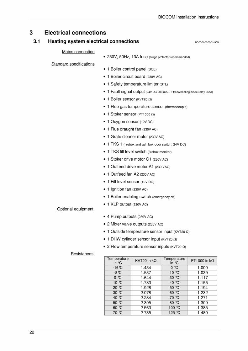
Resistances Temperature
in °C KVT20 in kΩ Temperature
in °C PT1000 in kΩ
-16°C 1.434 0 °C 1.000 -8°C 1.537 10 °C 1.039 0 °C 1.644 30 °C 1.117 10 °C 1.783 40 °C 1.155 20 °C 1.928 50 °C 1.194 30 °C 2.078 60 °C 1.232 40 °C 2.234 70 °C 1.271 50 °C 2.395 80 °C 1.309 60 °C 2.563 100 °C 1.385 70 °C 2.735 125 °C 1.480
BIOCOM Installation Instructions
23
RS (HKR 0)
CAN - Bus
HKR 0 230VAC
H
RG 2
SH - L H
CAN - BCE+ SH - L +
CA
N -
Bu
s
RG 0
RG 1 HCAN - BCE
SH L- +
(Taurus)KP
S Y-BUSSERVICE
BCEDisplay
E THERN. S D-CARD CAN CAN
CAN - Bus
3.2 Wiring requirements BS-03-02-00-00-01-IAEN
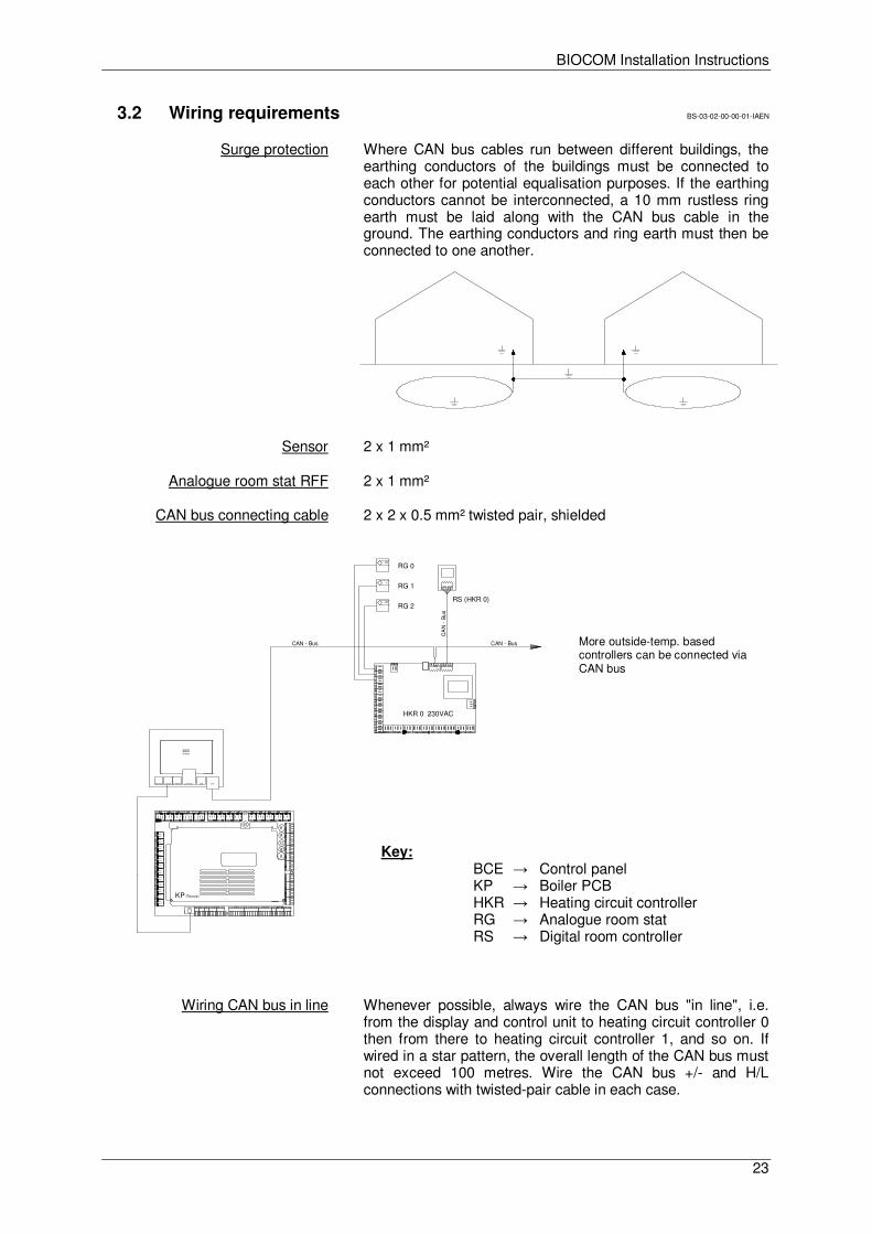
Surge protection Where CAN bus cables run between different buildings, the earthing conductors of the buildings must be connected to each other for potential equalisation purposes. If the earthing conductors cannot be interconnected, a 10 mm rustless ring earth must be laid along with the CAN bus cable in the ground. The earthing conductors and ring earth must then be connected to one another.
Sensor 2 x 1 mm²
Analogue room stat RFF 2 x 1 mm²
CAN bus connecting cable 2 x 2 x 0.5 mm² twisted pair, shielded
More outside-temp. based controllers can be connected via CAN bus
Key: BCE → Control panel KP → Boiler PCB HKR → Heating circuit controller RG → Analogue room stat RS → Digital room controller
Wiring CAN bus in line Whenever possible, always wire the CAN bus "in line", i.e. from the display and control unit to heating circuit controller 0 then from there to heating circuit controller 1, and so on. If wired in a star pattern, the overall length of the CAN bus must not exceed 100 metres. Wire the CAN bus +/- and H/L connections with twisted-pair cable in each case.
BIOCOM Installation Instructions
24
3.3 Electrical connections BS-03-03-00-00-01-IAEN
The electrical connections to the boiler system on site may only be made by an approved electrical installer observing all the applicable regulations. In addition, it is essential that electrical system components are protected against damage from heat radiation.
All boiler system internal wiring is wired up at the factory ready for use. The work required on site by the electrical installer consists only of connecting the mains power and wiring up and connecting the system components such as thermal store, CAN bus, heating circuit pumps, mixer valve motors, etc.
BS-03-03-00-01-01-IAEN
Mains power supply 230 V, 50 Hz, 13 A fuse
The mains power must be connected by means of the standard non-reversible power socket on the rear panel of the boiler. It must possible to isolate the system entirely from the mains without opening the switch panel cover, e.g. by means of an automatic circuit-breaker.
Correct polarity of the boiler's mains power connection must be ensured. The live (L) and neutral (N) phases must not be reversed as otherwise the short-circuit protection and safety system function cannot be guaranteed.
PH-03-03-00-02-01-IAEN
Opening switch panel Before the switch panel is opened, the boiler mains lead must be unplugged from the power supply. The system must not be live.
• Undo switch panel securing screw.
• Lift up front right panel section slightly, unclip and draw forwards to remove.
• The circuit boards with the associated connectors and fuses (see electrical wiring diagram) are located underneath it in an easily accessible position.
• The appropriate cable ducts must be used when connecting electrical leads.
BIOCOM Installation Instructions
25
PH-03-03-00-03-01-IAEN
Outside-temperature based controller The MKR outside-temperature based heating circuit controller set is offered as an option and activated on the boiler circuit board if required. The MK261 wall controller set, on the other hand, can only be fitted externally and connected to the system via the CAN bus. Operation and configuration is via the boiler control panel.
Set MKR The heating circuit controller can be used to control a DHW cylinder, a pumped heating circuit (HC0) and two mixed heating circuits (HC1, HC2). If heating circuit 0 is not used, the "supplementary" function can be used to operate a second DHW cylinder (HWP) or an external burner (EXTERNAL).
Wall controller set MK261 The wall controller set MK261 must be connected to the power supply at terminal H35 and connected to the control panel via the CAN bus.
The wall controller set can be used to control a DHW cylinder, a pumped heating circuit, 2 mixed heating circuits, one "supplementary function" (WWP or EXTERNAL) and a "district heating pipe" function (TSP/CP/FP). If the "supplementary" and "district heating" functions are not used, heating circuit 0 can be operated as a 3rd mixed circuit.
Analogue room stat The room stat should be connected to the relevant heating circuit controller input at terminals 1 and 2 (see electrical wiring diagram).
Digital room controller The room controller must be connected to the control panel (BCE) or wall controller set MK261 via CAN bus.
3rd mixed heating circuit Can only be activated on wall controller
Heating circuit 0 can only be used as a mixed heating circuit if the "supplementary" and "district heating" functions are not activated. Mixer valve 0 (MI 0) is connected to output terminals H25 and H26 and heating circuit pump 0 (HKP 0) to terminal H33 on the wall controller. The "district heating pipe" and "supplementary" functions are then not available.
2. DHW cylinder Can be activated internally and/or on the wall controller.
On the MKR controller set and on the MK261 wall controller set, an additional DHW cylinder (HWP) can be activated using the "supplementary" function. The district heating function on the wall controller set remains available but the 3rd mixed heating circuit cannot be connected.
External burner request Can be activated internally and/or on the wall controller.
On the MKR controller set and on the MK261 wall controller set, an external heating boiler (External) can be called for using the using the "supplementary" function. The load on the output must not exceed 230VAC and 2.0A. The district heating function on the wall controller set remains available but the 3rd mixed heating circuit cannot be connected.
BIOCOM Installation Instructions
26
Boiler cascade Up to four heating boilers can be operated in a cascade system (sequential control system) and must be connected in-line via a CAN bus. The CAN bus lead must be wired without connecting the + terminal.
Pay special attention to the section "Wiring requirements, Wiring CAN bus in line".
BS-03-03-00-04-01-IAEN
Emergency off switch According to prTRVB H 118, it must be possible to switch off the system using an emergency off switch fitted outside the boiler room near to the boiler room door. The burner must then shut down but the heating controller and all safety equipment must remain functional. Connected to the boiler enabling switch, terminals 22/23 on the boiler circuit board (see electrical wiring diagram).
BS-03-03-00-05-01-IAEN
Surge protection We recommend the installation of a power surge protector in the building's consumer unit.
Pay special attention to the section "Wiring requirements, Surge protection".
Earthing The entire system is to be joined to the earth circuit conductor via the connected piping system according to the regulations.
When connecting the earth circuit conductor pay particular attention to keeping the connecting runs as
short as possible.
Emergency power supply Only use regulated generators.
BIOCOM Installation Instructions
27
4 Final checks/Commissioning BS-04-00-00-00-01-IAEN
Final checks • After completing installation of the system, check
again that all joints and pipes are properly tightened and not leaking.
• Check that all covers are fitted and secured.
• Check that the fitting of all connections (water, flue, electrical, ...) has been done correctly.
• Check that all required safety signs and instructions are attached and hand over all documentation (operating and installation instructions) for the system.
• Check that all electrical connections have been properly wired before connecting the system to the power supply.
• Clean the system and clear up the installation site.
• Always leave the boiler room clean.
Initial commissioning Commissioning must only be carried out by GUNTAMATIC or a qualified specialist. The precondition is that the flue technician, heating installer and electrician have cleared the system for operation. The authorised GUNTAMATIC specialist will carry out the following work during commissioning:
• Check the entire system
• Check the electrical functions
• Adjust the programmer to the system
• Commission the system
• Explain to the user how the system functions and how to operate and clean it
• Record the details of the customer and the system and complete the commissioning log
Important → Any deficiencies identified must be recorded in writing and rectified within the following 4 weeks in order to maintain guarantee entitlement.
The fully completed commissioning checklist must be sent to GUNTAMATIC immediately as otherwise the
guarantee will be void.
Important → These installation instructions should not be destroyed after commissioning but kept permanently with the system together with the operating instructions.
BIOCOM Installation Instructions
28
5 Standards/Regulations BS-05-00-00-00-01-IAEN
The boiler is designed as a Class 3 appliance as defined by the draft standard ÖNORM EN 303-5 (CEN/TC7/WG 1 – Doc. N 36-D) of 15/12/1996 and the agreement of the [Austrian] Federal States according to Art. 15a BVG, in accordance with the Austrian fire safety regulations, safety systems, CE and on safety measures for small combustion heating systems and the combustion heating system approval regulations (LGB.33/1992) of the Austrian Federal State of Steiermark. The original design approval certificates (BLT Wieselburg, IBS Linz) are available for inspection at the manufacturer's offices. When connecting the boiler, the following general, standard and safety regulations must be followed in addition to the local fire safety and building control requirements:
• ÖNORM EN303-5 Boilers for solid fuels, manually and automatically stoked, with outputs up to 300 kW; terms, requirements, testing and identification;
• ÖNORM H 5195-1 Assessment and suitability of the heating water (minimum requirements for the heating water);
• ÖNORM M 7510 Guidelines for the inspection of central heating systems;
• ÖNORM M 7550 Central heating boilers up to 100°C – Terms, requirements, tests, standard identification;
• ÖNORM B 8130 Safety systems;
• ÖNORM B 8131 Sealed water-circulation heating systems, safety requirements;
• ÖNORM B 8133 Safety requirements, domestic hot water systems;
• pr TRVB H 118 Technical Directive on Preventative Fire Safety
• DIN 4751-1 / Safety systems for heating systems with flow temperatures up to 110°C (120°C in course of preparation);
• DIN 4751-2 / Water-circulation heating systems – sealed heating systems with thermostatic safety systems and flow temperatures up to 120°C – safety systems;
• DIN 4751-4 / Safety systems for domestic hot water systems with flow temperatures up to 120°C; sealed water-circulation heating systems with static heads over 15 m or rated heat outputs over 350 kW;
• DIN 1988 Mains water piping systems on building plots, technical regulations for construction and operation;
• DGVO §7(2) Technical requirements for systems for producing domestic hot water with a temperature not higher than 110°C which are stoked by hand with solid fuel;
• HEATING OUTPUT: The heating output is to be selected (set) by the engineer in accordance with the local heating system regulations so that the rated heat output does not exceed the heat requirement determined according to DIN 4701 or ÖNORM M7500;
• Swiss Clean Air Regulations (LRV)
• Swiss Regulations on Small Combustion Heating Systems
• VKF Fire Safety Directive for Heating Systems (Switzerland)
• SIA 384 (Switzerland)
BIOCOM Installation Instructions
29
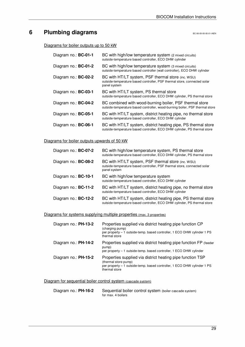
6 Plumbing diagrams BC-06-00-00-00-01-IAEN
Diagrams for boiler outputs up to 50 kW
Diagram no.: BC-01-1 BC with high/low temperature system (2 mixed circuits) outside-temperature based controller, ECO DHW cylinder
Diagram no.: BC-01-2 BC with high/low temperature system (3 mixed circuits) outside-temperature based controller (wall controller), ECO DHW cylinder
Diagram no.: BC-02-2 BC with HT/LT system, PSF thermal store (inc. WSU) outside-temperature based controller, PSF thermal store, connected solar panel system
Diagram no.: BC-03-1 BC with HT/LT system, PS thermal store outside-temperature based controller, ECO DHW cylinder, PS thermal store
Diagram no.: BC-04-2 BC combined with wood-burning boiler, PSF thermal store outside-temperature based controller, wood-burning boiler, PSF thermal store
Diagram no.: BC-05-1 BC with HT/LT system, district heating pipe, no thermal store outside-temperature based controller, ECO DHW cylinder
Diagram no.: BC-06-1 BC with HT/LT system, district heating pipe, PS thermal store outside-temperature based controller, ECO DHW cylinder, PS thermal store
Diagrams for boiler outputs upwards of 50 kW
Diagram no.: BC-07-2 BC with high/low temperature system, PS thermal store outside-temperature based controller, ECO DHW cylinder, PS thermal store
Diagram no.: BC-08-2 BC with HT/LT system, PSF thermal store (inc. WSU) outside-temperature based controller, PSF thermal store, connected solar panel system
Diagram no.: BC-10-1 BC with high/low temperature system outside-temperature based controller, ECO DHW cylinder
Diagram no.: BC-11-2 BC with HT/LT system, district heating pipe, no thermal store outside-temperature based controller, ECO DHW cylinder
Diagram no.: BC-12-2 BC with HT/LT system, district heating pipe, PS thermal store outside-temperature based controller, ECO DHW cylinder, PS thermal store
Diagrams for systems supplying multiple properties (max. 3 properties)
Diagram no.: PH-13-2 Properties supplied via district heating pipe function CP (charging pump) per property – 1 outside-temp. based controller, 1 ECO DHW cylinder 1 PS thermal store
Diagram no.: PH-14-2 Properties supplied via district heating pipe function FP (feeder pump) per property – 1 outside-temp. based controller, 1 ECO DHW cylinder
Diagram no.: PH-15-2 Properties supplied via district heating pipe function TSP (thermal store pump) per property – 1 outside-temp. based controller, 1 ECO DHW cylinder 1 PS thermal store
Diagram for sequential boiler control system (cascade system)
Diagram no.: PH-16-2 Sequential boiler control system (boiler cascade system) for max. 4 boilers
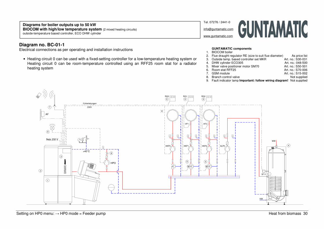
Setting on HP0 menu: → HP0 mode = Feeder pump Heat from biomass 30
230V
Fühlerleitungen
>40°C
1
2
3
7
9
Netz 230 V
AF
WW
HPO
8
HKP0
SF 0
KW
SLP0
M
5
M
5
HKP1 HKP2 4
6
RG0
VF1 VF2
6
RG1
6
RG2
Tel. 07276 / 2441-0
www.guntamatic.com
Diagram no. BC-01-1 Electrical connections as per operating and installation instructions
• Heating circuit 0 can be used with a fixed-setting controller for a low-temperature heating system or Heating circuit 0 can be room-temperature controlled using an RFF25 room stat for a radiator heating system
GUNTAMATIC components 1. BIOCOM boiler 2. Flue draught regulator RE (size to suit flue diameter) As price list 3. Outside temp. based controller set MKR Art. no.: S30-031 4. DHW cylinder ECO305 Art. no.: 048-500 5. Mixer valve positioner motor SM70 Art. no.: S50-501 6. Room stat RFF25 Art. no.: S70-006 7. GSM module Art. no.: S15-002 8. Branch control valve Not supplied 9. Fault indicator lamp Important: follow wiring diagram! Not supplied
Diagrams for boiler outputs up to 50 kW BIOCOM with high/low temperature system (2 mixed heating circuits) outside-temperature based controller, ECO DHW cylinder
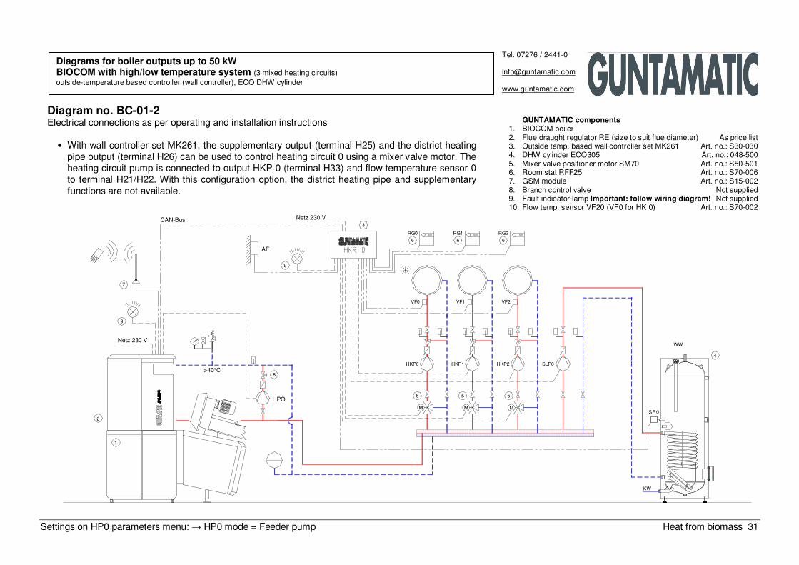
Settings on HP0 parameters menu: → HP0 mode = Feeder pump Heat from biomass 31
KW
1
2
Netz 230 V
9
7
M
HKP0
VF0
RG0
M
VF2
HKP2
M
HKP1
VF1
HPO
>40°C8
SF 0
5 5 5
SLP0
9
AF
CAN−Bus
6
Netz 230 V3
RG1
6
RG2
6
4
WW
Tel. 07276 / 2441-0
www.guntamatic.com
Diagram no. BC-01-2 Electrical connections as per operating and installation instructions
• With wall controller set MK261, the supplementary output (terminal H25) and the district heating pipe output (terminal H26) can be used to control heating circuit 0 using a mixer valve motor. The heating circuit pump is connected to output HKP 0 (terminal H33) and flow temperature sensor 0 to terminal H21/H22. With this configuration option, the district heating pipe and supplementary functions are not available.
Diagrams for boiler outputs up to 50 kW BIOCOM with high/low temperature system (3 mixed heating circuits) outside-temperature based controller (wall controller), ECO DHW cylinder
GUNTAMATIC components 1. BIOCOM boiler 2. Flue draught regulator RE (size to suit flue diameter) As price list 3. Outside temp. based wall controller set MK261 Art. no.: S30-030 4. DHW cylinder ECO305 Art. no.: 048-500 5. Mixer valve positioner motor SM70 Art. no.: S50-501 6. Room stat RFF25 Art. no.: S70-006 7. GSM module Art. no.: S15-002 8. Branch control valve Not supplied 9. Fault indicator lamp Important: follow wiring diagram! Not supplied 10. Flow temp. sensor VF20 (VF0 for HK 0) Art. no.: S70-002
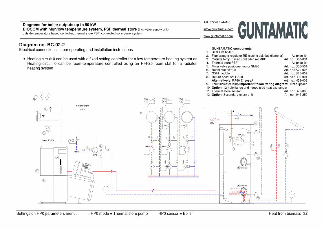
Settings on HP0 parameters menu: → HP0 mode = Thermal store pump HP0 sensor = Boiler Heat from biomass 32
2
1
>55°C
3HP0
Netz 230 V
9
8
AF
7 230V
Fühlerleitungen
T2
11
Option10
SF
M
5
M
5
HKP0 HKP1 HKP2
Option10
T3
11
12
Netz 230 V
VF1 VF2
RG0
6 6 6
RG1 RG2
WW 4
KW
Tel. 07276 / 2441-0
www.guntamatic.com
Diagram no. BC-02-2 Electrical connections as per operating and installation instructions
• Heating circuit 0 can be used with a fixed-setting controller for a low-temperature heating system or Heating circuit 0 can be room-temperature controlled using an RFF25 room stat for a radiator heating system
Diagrams for boiler outputs up to 50 kW BIOCOM with high/low temperature system, PSF thermal store (inc. water supply unit) outside-temperature based controller, thermal store PSF, connected solar panel system
GUNTAMATIC components 1. BIOCOM boiler 2. Flue draught regulator RE (size to suit flue diameter) As price list 3. Outside temp. based controller set MKR Art. no.: S30-031 4. Thermal store PSF As price list 5. Mixer valve positioner motor SM70 Art. no.: S50-501 6. Room stat RFF25 Art. no.: S70-006 7. GSM module Art. no.: S15-002 8. Return boost set RA60 Art. no.: H39-001
Alternatively: RA60 EnergieA Art. no.: H39-003 9. Fault indicator lamp Important: follow wiring diagram! Not supplied 10. Option: 12-hole flange and ridged pipe heat exchanger 11. Thermal store sensor Art. no.: S70-003 12. Option: Secondary return unit Art. no.: 045-250
Settings on HP0 parameters menu: → HP0 mode = Thermal store pump HP0 sensor = Boiler Heat from biomass 33
SLP0
HP0
Netz 230 V
2
1
9
3
>55°C
8 HKP0
5 5
M M
HKP1
VF1
HKP2
VF2
AF
7230V
Fühlerleitungen
RG0
6
RG1
6 6
RG2
10
WW
Puffer HP0
T2
KW
SF 0
T3
4
Tel. 07276 / 2441-0
www.guntamatic.com
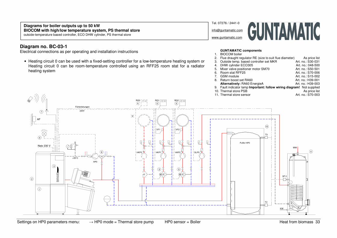
Diagram no. BC-03-1 Electrical connections as per operating and installation instructions
• Heating circuit 0 can be used with a fixed-setting controller for a low-temperature heating system or Heating circuit 0 can be room-temperature controlled using an RFF25 room stat for a radiator heating system
Diagrams for boiler outputs up to 50 kW BIOCOM with high/low temperature system, PS thermal store outside-temperature based controller, ECO DHW cylinder, PS thermal store
GUNTAMATIC components 1. BIOCOM boiler 2. Flue draught regulator RE (size to suit flue diameter) As price list 3. Outside temp. based controller set MKR Art. no.: S30-031 4. DHW cylinder ECO305 Art. no.: 048-500 5. Mixer valve positioner motor SM70 Art. no.: S50-501 6. Room stat RFF25 Art. no.: S70-006 7. GSM module Art. no.: S15-002 8. Return boost set RA60 Art. no.: H39-001
Alternatively: RA60 EnergieA Art. no.: H39-003 9. Fault indicator lamp Important: follow wiring diagram! Not supplied 10. Thermal store PSB As price list 11. Thermal store sensor Art. no.: S70-003
Settings on HP0 parameters menu: → HP0 mode = Thermal store pump HP0 sensor = Boiler Heat from biomass 34
Rauchrohr Feststoffkessel
Netz 230 V
2
> 50°C
1
KLP8
13
RGT> 88°C
Fühler T2−F, T3−F, T5−F
2
1
Netz 230 V
9
3
>55°C
HP0
8
230V
Fühlerleitungen7
AF
WW
VF1
HKP1HKP0
55
M M
HKP2
VF2
10
RG1
6
RG0
6 6
RG2
T2−F
T5−F
T3−F
11
11
13 Option
13 Option
T2
Netz 230 V
T3
SF
4
KW
Tel. 07276 / 2441-0
www.guntamatic.com
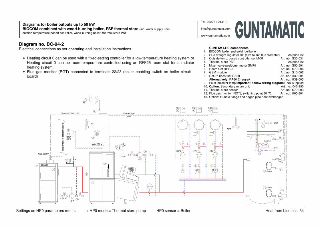
Diagram no. BC-04-2 Electrical connections as per operating and installation instructions
• Heating circuit 0 can be used with a fixed-setting controller for a low-temperature heating system or Heating circuit 0 can be room-temperature controlled using an RFF25 room stat for a radiator heating system.
• Flue gas monitor (RGT) connected to terminals 22/23 (boiler enabling switch on boiler circuit board)
Diagrams for boiler outputs up to 50 kW BIOCOM combined with wood-burning boiler, PSF thermal store (inc. water supply unit) outside-temperature based controller, wood-burning boiler, thermal store PSF
GUNTAMATIC components 1. BIOCOM boiler and solid fuel boiler 2. Flue draught regulator RE (size to suit flue diameter) As price list 3. Outside temp. based controller set MKR Art. no.: S30-031 4. Thermal store PSF As price list 5. Mixer valve positioner motor SM70 Art. no.: S50-501 6. Room stat RFF25 Art. no.: S70-006 7. GSM module Art. no.: S15-002 8. Return boost set RA60 Art. no.: H39-001
Alternatively: RA60 EnergieA Art. no.: H39-003 9. Fault indicator lamp Important: follow wiring diagram! Not supplied 10. Option: Secondary return unit Art. no.: 045-250 11. Thermal store sensor Art. no.: S70-003 12. Flue gas monitor (RGT), switching point 88 °C Art. no.: H00-801 13. Option: 12-hole flange and ridged pipe heat exchanger
Settings on HP0 parameters menu: → HP0 mode = Feeder pump Heat from biomass 35
Tel. 07276 / 2441-0
www.guntamatic.com
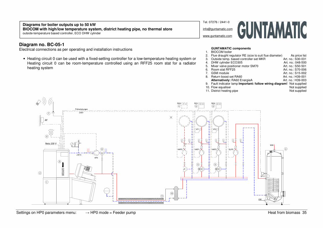
Diagram no. BC-05-1 Electrical connections as per operating and installation instructions
• Heating circuit 0 can be used with a fixed-setting controller for a low-temperature heating system or Heating circuit 0 can be room-temperature controlled using an RFF25 room stat for a radiator heating system
Diagrams for boiler outputs up to 50 kW BIOCOM with high/low temperature system, district heating pipe, no thermal store outside-temperature based controller, ECO DHW cylinder
GUNTAMATIC components 1. BIOCOM boiler 2. Flue draught regulator RE (size to suit flue diameter) As price list 3. Outside temp. based controller set MKR Art. no.: S30-031 4. DHW cylinder ECO305 Art. no.: 048-500 5. Mixer valve positioner motor SM70 Art. no.: S50-501 6. Room stat RFF25 Art. no.: S70-006 7. GSM module Art. no.: S15-002 8. Return boost set RA60 Art. no.: H39-001
Alternatively: RA60 EnergieA Art. no.: H39-003 9. Fault indicator lamp Important: follow wiring diagram! Not supplied 10. Flow equaliser Not supplied 11. District heating pipe Not supplied
SF 0
1
10
11
KW
Fühlerleitungen
Netz 230 V
2
3
>55°C
HP0
8
9
AF
7 230V
HKP0
MM
5 5
HKP1 HKP2 SLP0
VF1 VF2
RG0
6 6
RG1
6
RG2
WW
4
Settings on HP0 parameters menu: → HP0 mode = Thermal store pump HP0 sensor = Boiler Heat from biomass 36
2
1
3
Netz 230 V
9
>55°C
HP0
8
11
HKP0
5
M M
HKP1
5
VF1
HKP2
VF2
AF
7
Fühlerleitungen
230V
RG0
6 6
RG1 RG2
6
10
Puffer HP0
SLP0
T2
KW
SF 0
T3
WW
4
Tel. 07276 / 2441-0
www.guntamatic.com
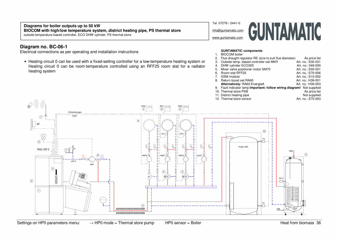
Diagram no. BC-06-1 Electrical connections as per operating and installation instructions
• Heating circuit 0 can be used with a fixed-setting controller for a low-temperature heating system or Heating circuit 0 can be room-temperature controlled using an RFF25 room stat for a radiator heating system
Diagrams for boiler outputs up to 50 kW BIOCOM with high/low temperature system, district heating pipe, PS thermal store outside-temperature based controller, ECO DHW cylinder, PS thermal store
GUNTAMATIC components 1. BIOCOM boiler 2. Flue draught regulator RE (size to suit flue diameter) As price list 3. Outside temp. based controller set MKR Art. no.: S30-031 4. DHW cylinder ECO305 Art. no.: 048-500 5. Mixer valve positioner motor SM70 Art. no.: S50-501 6. Room stat RFF25 Art. no.: S70-006 7. GSM module Art. no.: S15-002 8. Return boost set RA60 Art. no.: H39-001
Alternatively: RA60 EnergieA Art. no.: H39-003 9. Fault indicator lamp Important: follow wiring diagram! Not supplied 10. Thermal store PSB As price list 11. District heating pipe Not supplied 12. Thermal store sensor Art. no.: S70-003
Settings on HP0 parameters menu: → HP0 mode = Thermal store pump HP0 sensor = Boiler Heat from biomass 37
Tel. 07276 / 2441-0
www.guntamatic.com
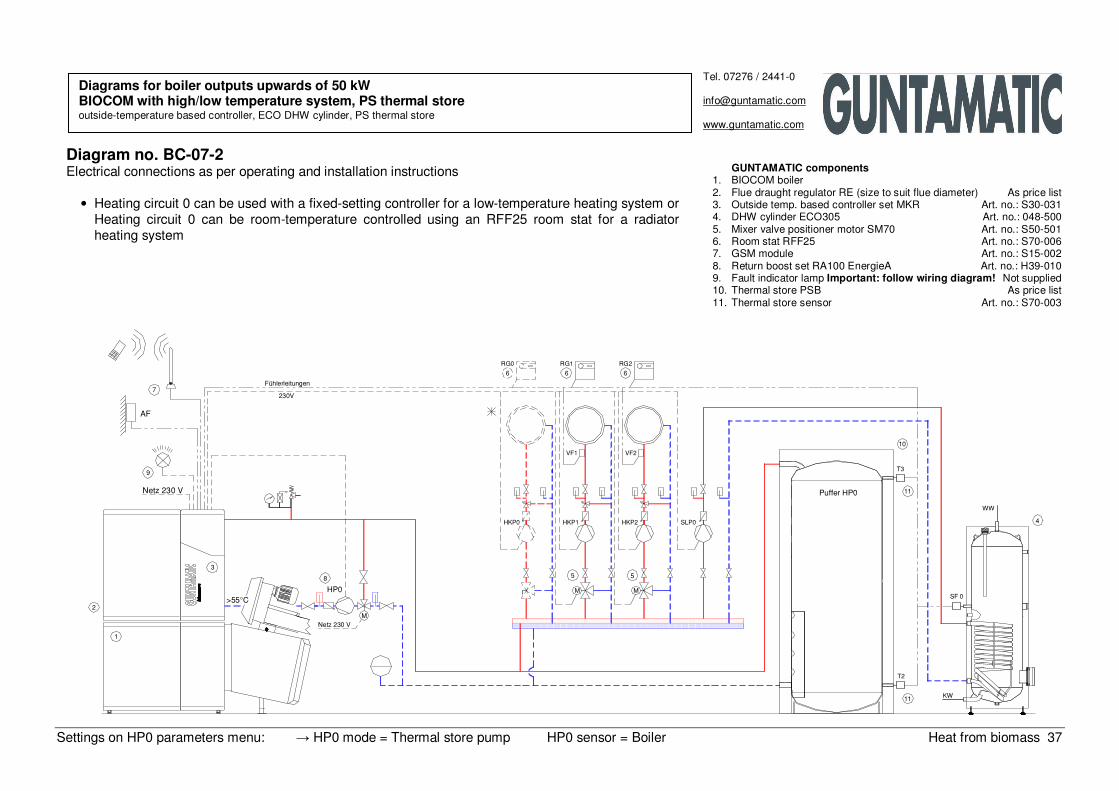
Diagram no. BC-07-2 Electrical connections as per operating and installation instructions
• Heating circuit 0 can be used with a fixed-setting controller for a low-temperature heating system or Heating circuit 0 can be room-temperature controlled using an RFF25 room stat for a radiator heating system
Diagrams for boiler outputs upwards of 50 kW BIOCOM with high/low temperature system, PS thermal store outside-temperature based controller, ECO DHW cylinder, PS thermal store
GUNTAMATIC components 1. BIOCOM boiler 2. Flue draught regulator RE (size to suit flue diameter) As price list 3. Outside temp. based controller set MKR Art. no.: S30-031 4. DHW cylinder ECO305 Art. no.: 048-500 5. Mixer valve positioner motor SM70 Art. no.: S50-501 6. Room stat RFF25 Art. no.: S70-006 7. GSM module Art. no.: S15-002 8. Return boost set RA100 EnergieA Art. no.: H39-010 9. Fault indicator lamp Important: follow wiring diagram! Not supplied 10. Thermal store PSB As price list 11. Thermal store sensor Art. no.: S70-003
2
1
>55°C
Netz 230 V
9
3
Netz 230 V
M
8
HP0
Fühlerleitungen
230V
AF
7
5
M
HKP0 HKP1
VF1
5
M
HKP2
VF2
SLP0
11
11
T2
Puffer HP0
T3
10
KW
SF 0
WW
4
RG0
6
RG1
6
RG2
6
Settings on HP0 parameters menu: → HP0 mode = Thermal store pump HP0 sensor = Boiler Heat from biomass 38
1
2
>55°C
3
9
Netz 230 V
AF
7230V
Fühlerleitungen
4WW
11
T2
10
10
Netz 230 V
M
8
HP0 M
5
M
5
HKP0 HKP1
VF1
HKP2
12
VF2
Option
Option
11
T3
SF
Netz 230 V
RG1RG0
6 6
RG2
6
KW
Tel. 07276 / 2441-0
www.guntamatic.com
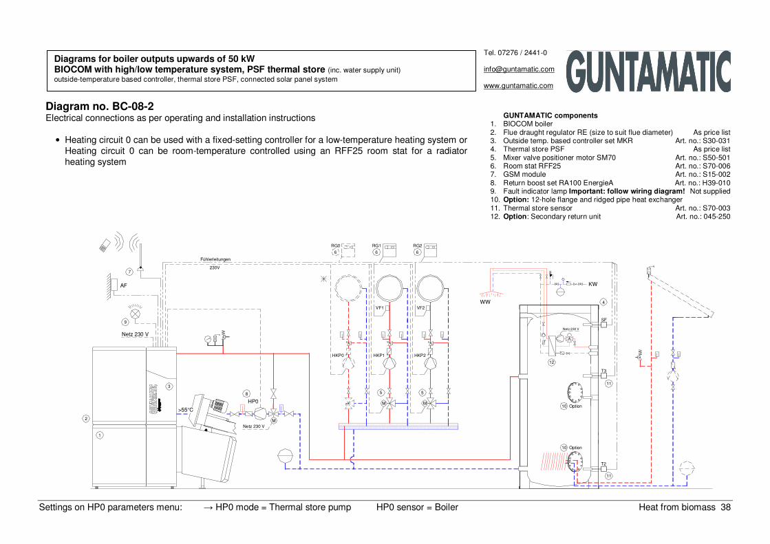
Diagram no. BC-08-2 Electrical connections as per operating and installation instructions
• Heating circuit 0 can be used with a fixed-setting controller for a low-temperature heating system or Heating circuit 0 can be room-temperature controlled using an RFF25 room stat for a radiator heating system
Diagrams for boiler outputs upwards of 50 kW BIOCOM with high/low temperature system, PSF thermal store (inc. water supply unit) outside-temperature based controller, thermal store PSF, connected solar panel system
GUNTAMATIC components 1. BIOCOM boiler 2. Flue draught regulator RE (size to suit flue diameter) As price list 3. Outside temp. based controller set MKR Art. no.: S30-031 4. Thermal store PSF As price list 5. Mixer valve positioner motor SM70 Art. no.: S50-501 6. Room stat RFF25 Art. no.: S70-006 7. GSM module Art. no.: S15-002 8. Return boost set RA100 EnergieA Art. no.: H39-010 9. Fault indicator lamp Important: follow wiring diagram! Not supplied 10. Option: 12-hole flange and ridged pipe heat exchanger 11. Thermal store sensor Art. no.: S70-003 12. Option: Secondary return unit Art. no.: 045-250
Settings on HP0 parameters menu: → HP0 mode = Feeder pump Heat from biomass 39
KW
>40°C
1
2
3
HP0
8
HKP0
5 5
M M
HKP1 HKP2 SLP0
Netz 230 V
9
AF
7230V
Fühlerleitungen
VF1 VF2
6
RG0
6 6
RG1 RG2
WW
SF 0
4
Tel. 07276 / 2441-0
www.guntamatic.com
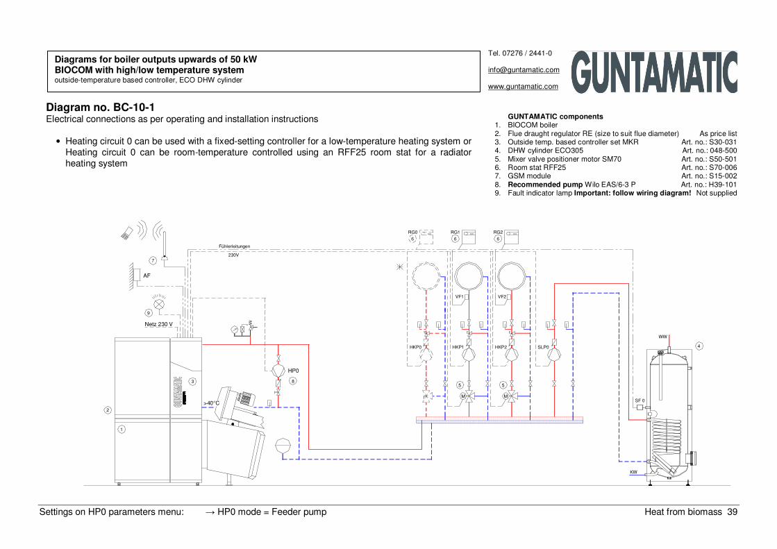
Diagram no. BC-10-1 Electrical connections as per operating and installation instructions
• Heating circuit 0 can be used with a fixed-setting controller for a low-temperature heating system or Heating circuit 0 can be room-temperature controlled using an RFF25 room stat for a radiator heating system
Diagrams for boiler outputs upwards of 50 kW BIOCOM with high/low temperature system outside-temperature based controller, ECO DHW cylinder
GUNTAMATIC components 1. BIOCOM boiler 2. Flue draught regulator RE (size to suit flue diameter) As price list 3. Outside temp. based controller set MKR Art. no.: S30-031 4. DHW cylinder ECO305 Art. no.: 048-500 5. Mixer valve positioner motor SM70 Art. no.: S50-501 6. Room stat RFF25 Art. no.: S70-006 7. GSM module Art. no.: S15-002 8. Recommended pump Wilo EAS/6-3 P Art. no.: H39-101 9. Fault indicator lamp Important: follow wiring diagram! Not supplied
Settings on HP0 parameters menu: → HP0 mode = Feeder pump Heat from biomass 40
1
2
>55°C
3
SF 0
Netz 230 V
M
10
11
KW
HKP0
8
HP0 M
5
M
5
HKP1 HKP2 SLP0
4
WW
Netz 230 V
9
AF
7230V
Fühlerleitungen
666
VF1 VF2
RG0 RG1 RG2
Tel. 07276 / 2441-0
www.guntamatic.com
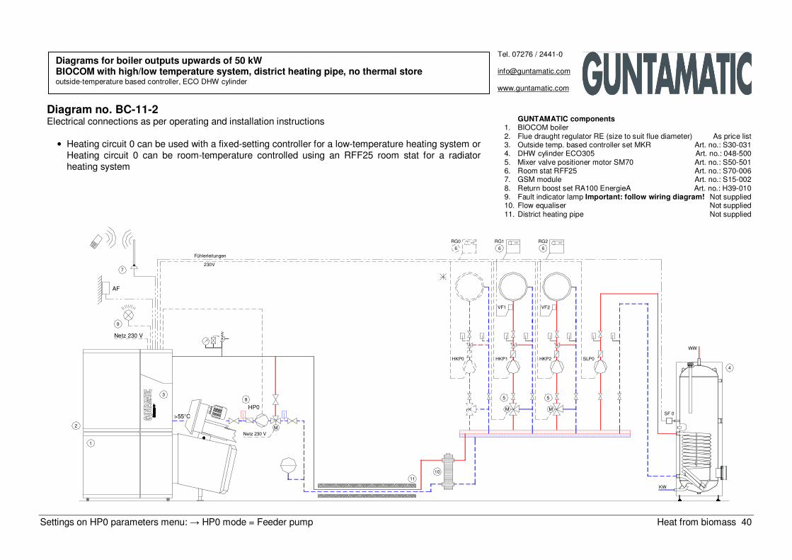
Diagram no. BC-11-2 Electrical connections as per operating and installation instructions
• Heating circuit 0 can be used with a fixed-setting controller for a low-temperature heating system or Heating circuit 0 can be room-temperature controlled using an RFF25 room stat for a radiator heating system
Diagrams for boiler outputs upwards of 50 kW BIOCOM with high/low temperature system, district heating pipe, no thermal store outside-temperature based controller, ECO DHW cylinder
GUNTAMATIC components 1. BIOCOM boiler 2. Flue draught regulator RE (size to suit flue diameter) As price list 3. Outside temp. based controller set MKR Art. no.: S30-031 4. DHW cylinder ECO305 Art. no.: 048-500 5. Mixer valve positioner motor SM70 Art. no.: S50-501 6. Room stat RFF25 Art. no.: S70-006 7. GSM module Art. no.: S15-002 8. Return boost set RA100 EnergieA Art. no.: H39-010 9. Fault indicator lamp Important: follow wiring diagram! Not supplied 10. Flow equaliser Not supplied 11. District heating pipe Not supplied
Settings on HP0 parameters menu: → HP0 mode = Thermal store pump HP0 sensor = Boiler Heat from biomass 41
2
1
>55°C
3
Netz 230 V
9
8
Netz 230 V
M
HP0
Fühlerleitungen
AF
7230V
10
11
M
HKP0 HKP1
5
VF1
5
M
SLP0HKP2
VF2
T2
Puffer HP0
T3
KW
SF 0
WW
4
6
RG0 RG1
6
RG2
6
Tel. 07276 / 2441-0
www.guntamatic.com
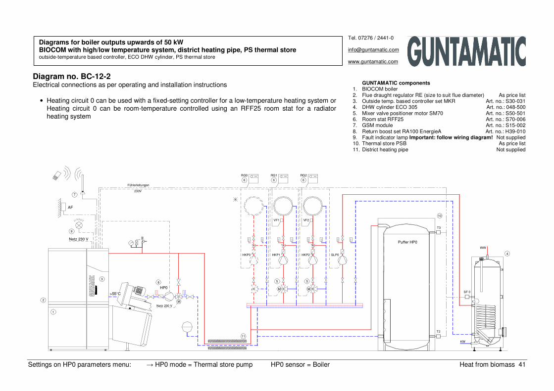
Diagram no. BC-12-2 Electrical connections as per operating and installation instructions
• Heating circuit 0 can be used with a fixed-setting controller for a low-temperature heating system or Heating circuit 0 can be room-temperature controlled using an RFF25 room stat for a radiator heating system
Diagrams for boiler outputs upwards of 50 kW BIOCOM with high/low temperature system, district heating pipe, PS thermal store outside-temperature based controller, ECO DHW cylinder, PS thermal store
GUNTAMATIC components 1. BIOCOM boiler 2. Flue draught regulator RE (size to suit flue diameter) As price list 3. Outside temp. based controller set MKR Art. no.: S30-031 4. DHW cylinder ECO 305 Art. no.: 048-500 5. Mixer valve positioner motor SM70 Art. no.: S50-501 6. Room stat RFF25 Art. no.: S70-006 7. GSM module Art. no.: S15-002 8. Return boost set RA100 EnergieA Art. no.: H39-010 9. Fault indicator lamp Important: follow wiring diagram! Not supplied 10. Thermal store PSB As price list 11. District heating pipe Not supplied
Settings on HP0 parameters menu: → HP0 mode = Thermal store pump Heat from biomass 42
Netz
1
2
CAN−Bus
7
Heizraum
T3
Puffer HP0
8
HP0
12
>55°C
10
Einstellung im Menü Parameter HP0: Betrieb HP0 = Pufferpumpe
T2
Puffer 1
5
T2−1
RG6
3Netz 230 V
HKR 2
LAP
9
CAN−Bus
*
Puffer 2
T3−2
HKP65
10
T2−2
9
LAP
HKP3
13
13
Fernleitung 2 auf LAP einstellen
Haus 2
Fernleitung 1 auf LAP einstellen
WW
411
SF 1M
KW
6RG8
M
RG7
VF8
HKP8 SLP2
SF 2M
11 4
WW
VF7
HKP7
M
KW
RG5
6
VF5
RG4
VF4
HKP5HKP4 SLP1
RG0
3Netz 230 V
AF HKR 0
CAN−Bus
**
Puffer 0
T3−0
5HKP0
T2−0
RG3
3Netz 230 V
HKR 1
9
LAP
CAN−Bus
*
T3−1
10
10
13
Haus 1
Fernleitung 0 auf LAP einstellen
Haus 0
6RG2RG1
WW
VF2
411
SF 0M
HKP2 SLP0
VF1
M
HKP1
KW
Tel. 07276 / 2441-0
www.guntamatic.com
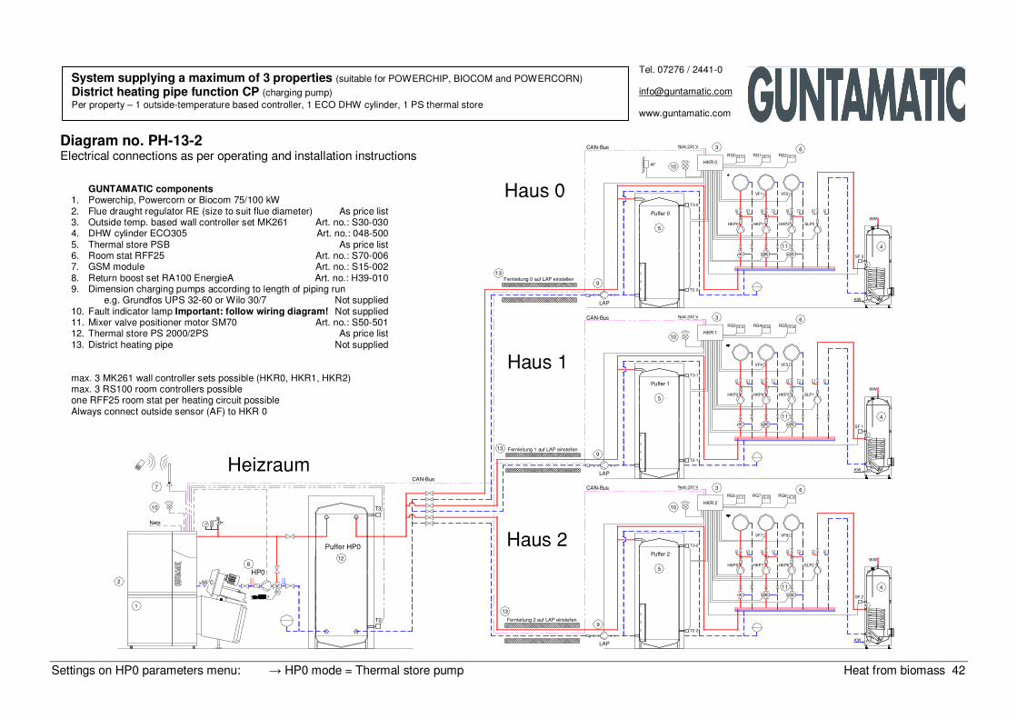
Diagram no. PH-13-2 Electrical connections as per operating and installation instructions
System supplying a maximum of 3 properties (suitable for POWERCHIP, BIOCOM and POWERCORN)
District heating pipe function CP (charging pump) Per property – 1 outside-temperature based controller, 1 ECO DHW cylinder, 1 PS thermal store
GUNTAMATIC components 1. Powerchip, Powercorn or Biocom 75/100 kW 2. Flue draught regulator RE (size to suit flue diameter) As price list 3. Outside temp. based wall controller set MK261 Art. no.: S30-030 4. DHW cylinder ECO305 Art. no.: 048-500 5. Thermal store PSB As price list 6. Room stat RFF25 Art. no.: S70-006 7. GSM module Art. no.: S15-002 8. Return boost set RA100 EnergieA Art. no.: H39-010 9. Dimension charging pumps according to length of piping run e.g. Grundfos UPS 32-60 or Wilo 30/7 Not supplied 10. Fault indicator lamp Important: follow wiring diagram! Not supplied 11. Mixer valve positioner motor SM70 Art. no.: S50-501 12. Thermal store PS 2000/2PS As price list 13. District heating pipe Not supplied max. 3 MK261 wall controller sets possible (HKR0, HKR1, HKR2) max. 3 RS100 room controllers possible one RFF25 room stat per heating circuit possible Always connect outside sensor (AF) to HKR 0
Settings on HP0 parameters menu: → HP0 mode = Thermal store pump Heat from biomass 43
CAN−Bus max. 100 m
1
2
7
Heizraum
T3
Puffer HP0
12
10
Netz
>55°C
8
HP0
T2
Haus 1
HKP3
5
RG6
3Netz 230 V
ZUP9
CAN−Bus
**10
HKP6
5
HKR 2
ZUP9
13
13 Fernleitung 2 auf ZUP einstellen
Haus 2
Fernleitung 1 auf ZUP einstellen
VF4 VF5
SLP1
SF 1M
4
KW
6
HKP4
M
RG7 RG8
11
HKP5
SLP2
SF 2M
4
WW
VF7
HKP7
M
11
HKP8
VF8
KW
6RG4 RG5
WW
RG0
Netz 230 V 3CAN−Bus
**10
HKP0
5
RG3
3Netz 230 V
ZUP9
CAN−Bus
**10
HKR 1
AF HKR 0
13 Fernleitung 0 auf ZUP einstellen
Haus 0
6RG1 RG2
SLP0
SF 0M
4
WW
VF1
HKP1
M
11
HKP2
VF2
KW
Tel. 07276 / 2441-0
www.guntamatic.com
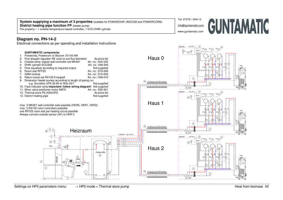
Diagram no. PH-14-2 Electrical connections as per operating and installation instructions
System supplying a maximum of 3 properties (suitable for POWERCHIP, BIOCOM and POWERCORN)
District heating pipe function FP (feeder pump) Per property – 1 outside-temperature based controller, 1 ECO DHW cylinder
GUNTAMATIC components 1. Powerchip, Powercorn or Biocom 75/100 kW 2. Flue draught regulator RE (size to suit flue diameter) As price list 3. Outside temp. based wall controller set MK261 Art. no.: S30-030 4. DHW cylinder ECO305 Art. no.: 048-500 5. Flow equaliser according to required output Not supplied 6. Room stat RFF25 Art. no.: S70-006 7. GSM module Art. no.: S15-002 8. Return boost set RA100 EnergieA Art. no.: H39-010 9. Dimension feeder pumps according to length of piping run e.g. Grundfos UPS 32-60 or Wilo 30/7 Not supplied 10. Fault indicator lamp Important: follow wiring diagram! Not supplied 11. Mixer valve positioner motor SM70 Art. no.: S50-501 12. Thermal store PS 2000/2PS As price list 13. District heating pipe Not supplied max. 3 MK261 wall controller sets possible (HKR0, HKR1, HKR2) max. 3 RS100 room controllers possible one RFF25 room stat per heating circuit possible Always connect outside sensor (AF) to HKR 0
Setting on HP0 parameters menu: → HP0 mode = Feeder pump Heat from biomass 44
Netz
2
1
CAN−Bus max. 100 m
7
Heizraum
1310
8
>55°C
HP0
PUP
RG3
HKP3
HKP6
RG6
Netz 230 V 3CAN−Bus
10HKR 1
*
T3−1
5
Puffer 1
T2−1
Netz 230 V 3
9
PUP
CAN−Bus
10HKR 2
*
T3−2
5
Puffer 2
T2−2
9
PUP
12
12 Fernleitung 2 auf PUP einstellen
Haus 2
Fernleitung 1 auf PUP einstellen
Haus 1
6RG4 RG5
VF4 VF5
WW
SLP1
4
SF 1
RG0
HKP0
10HKR 0
**
AF
6
KW
HKP4 HKP5
11
MM
WW
SLP2
SF 2
4
VF8VF7
HKP7 HKP8
MM
11
RG7 RG8
KW
5
Puffer 0
T3−0
T2−0
9
3CAN−Bus Netz 230 V
12 Fernleitung 0 auf PUP einstellen
Haus 0
6
WWSLP0
4
SF 0
RG1 RG2
VF1 VF2
HKP1 HKP2
MM
11
KW
Tel. 07276 / 2441-0
www.guntamatic.com
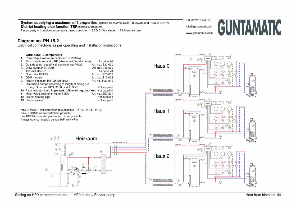
Diagram no. PH-15-2 Electrical connections as per operating and installation instructions
System supplying a maximum of 3 properties (suitable for POWERCHIP, BIOCOM and POWERCORN)
District heating pipe function TSP(thermal store pump) Per property – 1 outside-temperature based controller, 1 ECO DHW cylinder, 1 PS thermal store
GUNTAMATIC components 1. Powerchip, Powercorn or Biocom 75/100 kW 2. Flue draught regulator RE (size to suit flue diameter) As price list 3. Outside temp. based wall controller set MK261 Art. no.: S30-030 4. DHW cylinder ECO305 Art. no.: 048-500 5. Thermal store PSB As price list 6. Room stat RFF25 Art. no.: S70-006 7. GSM module Art. no.: S15-002 8. Return boost set RA100 EnergieA Art. no.: H39-010 9. Dimension pumps according to length of piping run e.g. Grundfos UPS 32-60 or Wilo 30/7 Not supplied 10. Fault indicator lamp Important: follow wiring diagram! Not supplied 11. Mixer valve positioner motor SM70 Art. no.: S50-501 12. District heating pipe Not supplied 13. Flow equaliser Not supplied max. 3 MK261 wall controller sets possible (HKR0, HKR1, HKR2) max. 3 RS100 room controllers possible one RFF25 room stat per heating circuit possible Always connect outside sensor (AF) to HKR 0
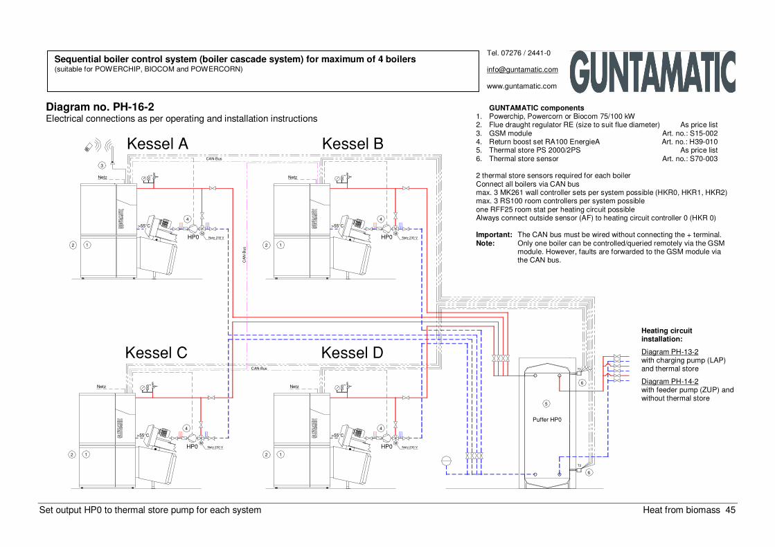
Set output HP0 to thermal store pump for each system Heat from biomass 45
44
M
Netz 230 V
>55°C
1212
HP0M
Netz 230 VHP0
>55°C
T2
6
M
Netz 230 V
Netz
CAN−Bus
Netz
3
Kessel A
>55°C
4
2 1CAN−Bus
12
HP0
Netz
CAN−Bus
Netz
Kessel C
M
Netz 230 V
Kessel B
4
HP0
5
Puffer HP0
>55°C
Kessel DT3
6
Tel. 07276 / 2441-0
www.guntamatic.com
Diagram no. PH-16-2 Electrical connections as per operating and installation instructions
Sequential boiler control system (boiler cascade system) for maximum of 4 boilers (suitable for POWERCHIP, BIOCOM and POWERCORN)
GUNTAMATIC components 1. Powerchip, Powercorn or Biocom 75/100 kW 2. Flue draught regulator RE (size to suit flue diameter) As price list 3. GSM module Art. no.: S15-002 4. Return boost set RA100 EnergieA Art. no.: H39-010 5. Thermal store PS 2000/2PS As price list 6. Thermal store sensor Art. no.: S70-003 2 thermal store sensors required for each boiler Connect all boilers via CAN bus max. 3 MK261 wall controller sets per system possible (HKR0, HKR1, HKR2) max. 3 RS100 room controllers per system possible one RFF25 room stat per heating circuit possible Always connect outside sensor (AF) to heating circuit controller 0 (HKR 0) Important: The CAN bus must be wired without connecting the + terminal. Note: Only one boiler can be controlled/queried remotely via the GSM
module. However, faults are forwarded to the GSM module via the CAN bus.
Heating circuit installation:
Diagram PH-13-2 with charging pump (LAP) and thermal store
Diagram PH-14-2 with feeder pump (ZUP) and without thermal store
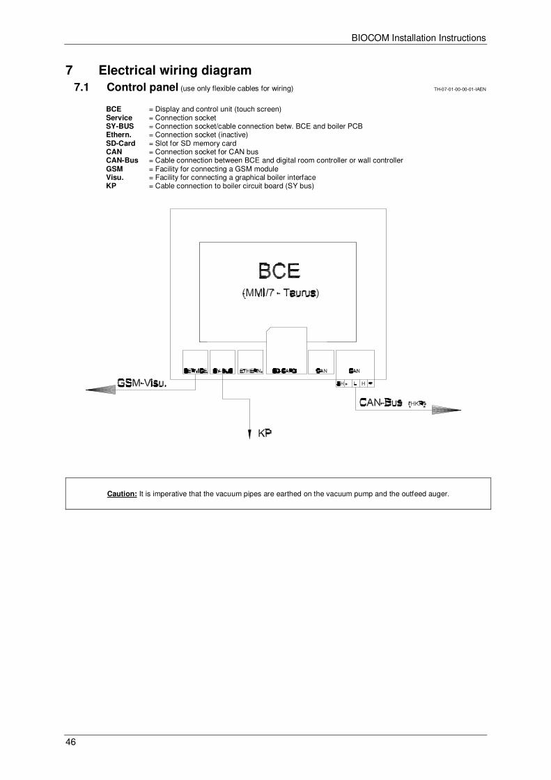
BIOCOM Installation Instructions
46
7 Electrical wiring diagram BS-07-00-00-00-01-IAEN
7.1 Control panel (use only flexible cables for wiring) TH-07-01-00-00-01-IAEN
BCE = Display and control unit (touch screen) Service = Connection socket SY-BUS = Connection socket/cable connection betw. BCE and boiler PCB Ethern. = Connection socket (inactive) SD-Card = Slot for SD memory card CAN = Connection socket for CAN bus CAN-Bus = Cable connection between BCE and digital room controller or wall controller GSM = Facility for connecting a GSM module Visu. = Facility for connecting a graphical boiler interface KP = Cable connection to boiler circuit board (SY bus)
Caution: It is imperative that the vacuum pipes are earthed on the vacuum pump and the outfeed auger.
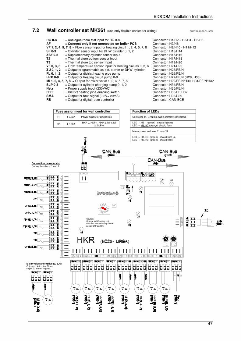
BIOCOM Installation Instructions
47
7.2 Wall controller set MK261 (use only flexible cables for wiring) PH-07-02-00-00-01-IAEN
RG 0-8 = Analogue room stat input for HC 0-8 Connector: H1/H2 – H3/H4 - H5/H6 AF = Connect only if not connected on boiler PCB Connector: H7/H8 VF 1, 2, 4, 5, 7, 8 = Flow sensor input for heating circuit 1, 2, 4, 5, 7, 8 Connector: H9/H10 - H11/H12 SF 0-3 = Cylinder sensor input for DHW cylinder 0, 1, 2 Connector: H13/H14 ZSF 0-2 = Supplementary cylinder sensor input Connector: H15/H16 T2 = Thermal store bottom sensor input Connector: H17/H18 T3 = Thermal store top sensor input Connector: H19/H20 VF 0, 3, 6 = Flow temperature sensor input for heating circuits 0, 3, 6 Connector: H21/H22 ZU 0, 1, 2 = Output programmable as ext. burner or DHW cylinder Connector: H25/PE/N FL 0, 1, 2 = Output for district heating pipe pump Connector: H26/PE/N HKP 0-8 = Output for heating circuit pump 0-8 Connector: H27/PE/N (H28, H33) Mi 1, 2, 4, 5, 7, 8 = Output for mixer valve 1, 2, 4, 5, 7, 8 Connector: H29/PE/N/H30, H31/PE/N/H32 SLP 0-3 = Output for cylinder charging pump 0, 1, 2 Connector: H34/PE/N Netz = Power supply input (230VAC) Connector: H35/PE/N FFR = District heating pipe enabling switch Connector: H36/PE/H37 SMA = Output for fault signal (9.2V= 20mA) Connector: H38/H39 RS = Output for digital room controller Connector: CAN-BCE
Standard setting for S1: both DIP switches "ON"
Caution: Change to S2 setting only effective after switching mains power OFF and ON
Function of LEDs
Controller on, CAN bus cable correctly connected:
LED → H5 (green) should light up LED → H6, H7 (orange) should flash
Mains power and fuse F1 are OK
LED → H1, H4 (green) should light up LED → H2, H3 (green) should flash
Fuse assignment for wall controller
F1 T 0.63A Power supply for electronics
F2 T 6.30A HKP 0, HKP 1, HKP 2, MI 1, MI 2, SLP 0
Connection on room stat Connect contacts 1 and 2
Mixer valve alternative (0, 3, 6): Only possible if output FL and output ZU are not required.
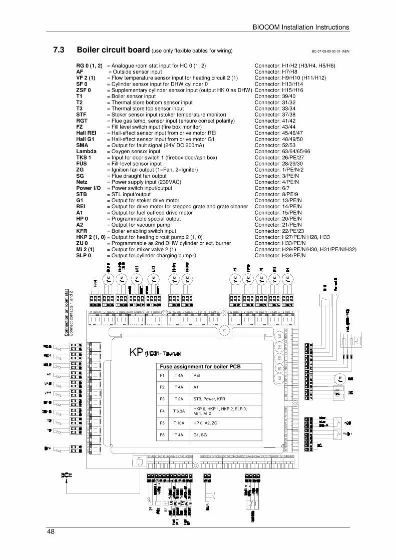
BIOCOM Installation Instructions
48
7.3 Boiler circuit board (use only flexible cables for wiring) BC-07-03-00-00-01-IAEN
RG 0 (1, 2) = Analogue room stat input for HC 0 (1, 2) Connector: H1/H2 (H3/H4, H5/H6) AF = Outside sensor input Connector: H7/H8 VF 2 (1) = Flow temperature sensor input for heating circuit 2 (1) Connector: H9/H10 (H11/H12) SF 0 = Cylinder sensor input for DHW cylinder 0 Connector: H13/H14 ZSF 0 = Supplementary cylinder sensor input (output HK 0 as DHW) Connector: H15/H16 T1 = Boiler sensor input Connector: 39/40 T2 = Thermal store bottom sensor input Connector: 31/32 T3 = Thermal store top sensor input Connector: 33/34 STF = Stoker sensor input (stoker temperature monitor) Connector: 37/38 RGT = Flue gas temp. sensor input (ensure correct polarity) Connector: 41/42 FZ = Fill level switch input (fire box monitor) Connector: 43/44 Hall REI = Hall-effect sensor input from drive motor REI Connector: 45/46/47 Hall G1 = Hall-effect sensor input from drive motor G1 Connector: 48/49/50 SMA = Output for fault signal (24V DC 200mA) Connector: 52/53 Lambda = Oxygen sensor input Connector: 63/64/65/66 TKS 1 = Input for door switch 1 (firebox door/ash box) Connector: 26/PE/27 FÜS = Fill-level sensor input Connector: 28/29/30 ZG = Ignition fan output (1=Fan, 2=Igniter) Connector: 1/PE/N/2 SG = Flue draught fan output Connector: 3/PE/N Netz = Power supply input (230VAC) Connector: 4/PE/N Power I/O = Power switch input/output Connector: 6/7 STB = STL input/output Connector: 8/PE/9 G1 = Output for stoker drive motor Connector: 13/PE/N REI = Output for drive motor for stepped grate and grate cleaner Connector: 14/PE/N A1 = Output for fuel outfeed drive motor Connector: 15/PE/N HP 0 = Programmable special output Connector: 20/PE/N A2 = Output for vacuum pump Connector: 21/PE/N KFR = Boiler enabling switch input Connector: 22/PE/23 HKP 2 (1, 0) = Output for heating circuit pump 2 (1, 0) Connector: H27/PE/N H28, H33 ZU 0 = Programmable as 2nd DHW cylinder or ext. burner Connector: H33/PE/N Mi 2 (1) = Output for mixer valve 2 (1) Connector: H29/PE/N/H30, H31/PE/N/H32) SLP 0 = Output for cylinder charging pump 0 Connector: H34/PE/N
Fuse assignment for boiler PCB
F1 T 4A REI
F2 T 4A A1
F3 T 2A STB, Power, KFR
F4 T 6.3A HKP 0, HKP 1, HKP 2, SLP 0, Mi 1, Mi 2
F5 T 10A HP 0, A2, ZG
F6 T 4A G1, SG
Co
nn
ecti
on
on
ro
om
sta
t C
onne
ct c
onta
cts
1 an
d 2
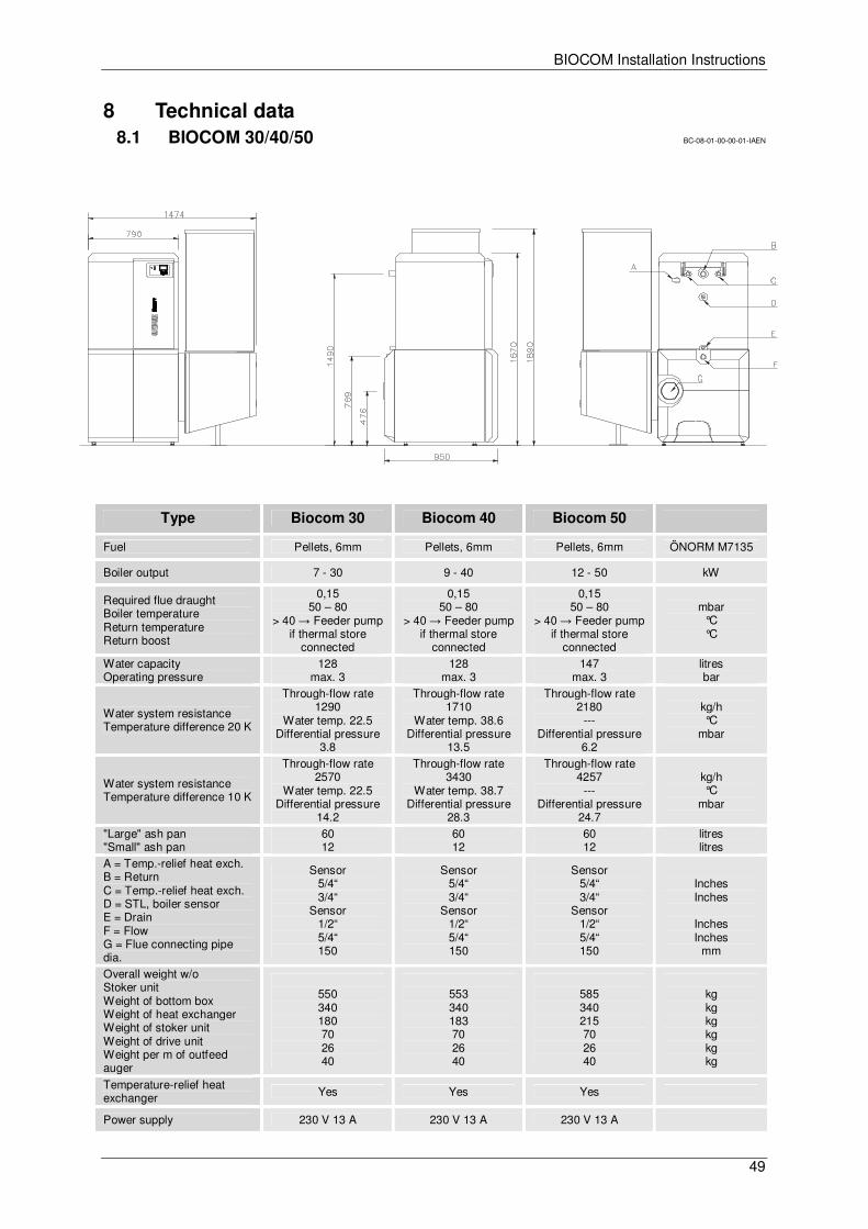
BIOCOM Installation Instructions
49
8 Technical data BS-08-00-00-00-01-IAEN
8.1 BIOCOM 30/40/50 BC-08-01-00-00-01-IAEN
Type Biocom 30 Biocom 40 Biocom 50
Fuel Pellets, 6mm Pellets, 6mm Pellets, 6mm ÖNORM M7135
Boiler output 7 - 30 9 - 40 12 - 50 kW
Required flue draught Boiler temperature Return temperature Return boost
0,15 50 – 80
> 40 → Feeder pump if thermal store
connected
0,15 50 – 80
> 40 → Feeder pump if thermal store
connected
0,15 50 – 80
> 40 → Feeder pump if thermal store
connected
mbar °C °C
Water capacity Operating pressure
128 max. 3
128 max. 3
147 max. 3
litres bar
Water system resistance Temperature difference 20 K
Through-flow rate 1290
Water temp. 22.5 Differential pressure
3.8
Through-flow rate 1710
Water temp. 38.6 Differential pressure
13.5
Through-flow rate 2180
--- Differential pressure
6.2
kg/h °C
mbar
Water system resistance Temperature difference 10 K
Through-flow rate 2570
Water temp. 22.5 Differential pressure
14.2
Through-flow rate 3430
Water temp. 38.7 Differential pressure
28.3
Through-flow rate 4257
--- Differential pressure
24.7
kg/h °C
mbar
"Large" ash pan "Small" ash pan
60 12
60 12
60 12
litres litres
A = Temp.-relief heat exch. B = Return C = Temp.-relief heat exch. D = STL, boiler sensor E = Drain F = Flow G = Flue connecting pipe dia.
Sensor 5/4“ 3/4“
Sensor 1/2“ 5/4“ 150
Sensor 5/4“ 3/4“
Sensor 1/2“ 5/4“ 150
Sensor 5/4“ 3/4“
Sensor 1/2“ 5/4“ 150
Inches Inches
Inches Inches
mm
Overall weight w/o Stoker unit Weight of bottom box Weight of heat exchanger Weight of stoker unit Weight of drive unit Weight per m of outfeed auger
550 340 180 70 26 40
553 340 183 70 26 40
585 340 215 70 26 40
kg kg kg kg kg kg
Temperature-relief heat exchanger Yes Yes Yes
Power supply 230 V 13 A 230 V 13 A 230 V 13 A
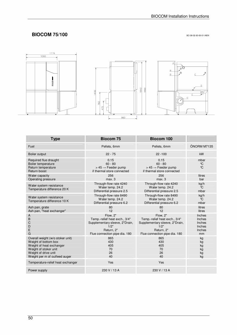
BIOCOM Installation Instructions
50
BIOCOM 75/100 BC-08-02-00-00-01-IAEN
Type Biocom 75 Biocom 100
Fuel Pellets, 6mm Pellets, 6mm ÖNORM M7135
Boiler output 22 - 75 22 -100 kW
Required flue draught Boiler temperature Return temperature Return boost
0.15 60 - 80
> 45 → Feeder pump if thermal store connected
0.15 60 - 80
> 45 → Feeder pump if thermal store connected
mbar °C °C
Water capacity Operating pressure
256 max. 3
256 max. 3
litres bar
Water system resistance Temperature difference 20 K
Through-flow rate 4240 Water temp. 24.2
Differential pressure 2.5
Through-flow rate 4240 Water temp. 24.2
Differential pressure 2.5
kg/h °C
mbar
Water system resistance Temperature difference 10 K
Through-flow rate 8490 Water temp. 24.2
Differential pressure 6.2
Through-flow rate 8490 Water temp. 24.2
Differential pressure 6.2
kg/h °C
mbar
Ash pan, grate Ash pan, "heat exchanger"
80 12
80 12
litres litres
A B C D E G
Flow, 2" Temp.-relief heat exch., 3/4"
Supplementary sleeve, 2"Drain, 1/2"
Return, 2" Flue connection pipe dia. 180
Flow, 2" Temp.-relief heat exch., 3/4"
Supplementary sleeve, 2"Drain, 1/2"
Return, 2" Flue connection pipe dia. 180
Inches Inches Inches Inches Inches
mm
Overall weight (w/o stoker unit) Weight of bottom box Weight of heat exchanger Weight of stoker unit Weight of drive unit Weight per m of outfeed auger
865 430 405 70 26 40
865 430 405 70 26 40
kg kg kg kg kg kg
Temperature-relief heat exchanger Yes Yes
Power supply 230 V / 13 A 230 V / 13 A
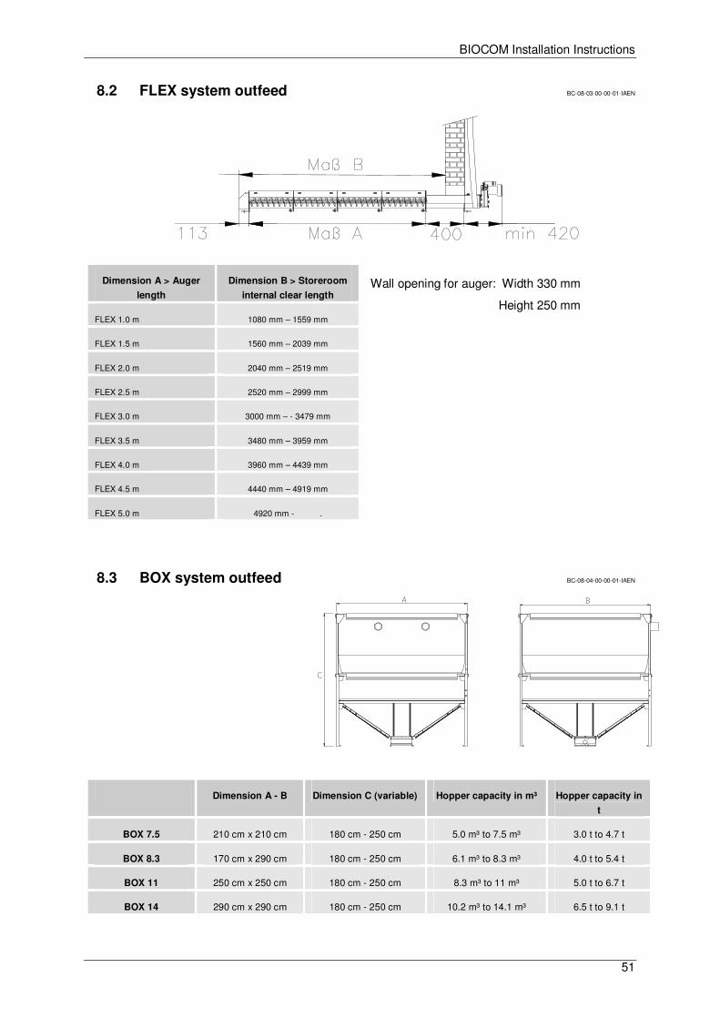
BIOCOM Installation Instructions
51
8.2 FLEX system outfeed BC-08-03-00-00-01-IAEN
Wall opening for auger: Width 330 mm
Height 250 mm
8.3 BOX system outfeed BC-08-04-00-00-01-IAEN
Dimension A > Auger
length
Dimension B > Storeroom
internal clear length
FLEX 1.0 m 1080 mm – 1559 mm
FLEX 1.5 m 1560 mm – 2039 mm
FLEX 2.0 m 2040 mm – 2519 mm
FLEX 2.5 m 2520 mm – 2999 mm
FLEX 3.0 m 3000 mm – - 3479 mm
FLEX 3.5 m 3480 mm – 3959 mm
FLEX 4.0 m 3960 mm – 4439 mm
FLEX 4.5 m 4440 mm – 4919 mm
FLEX 5.0 m 4920 mm - .
Dimension A - B Dimension C (variable) Hopper capacity in m³ Hopper capacity in
t
BOX 7.5 210 cm x 210 cm 180 cm - 250 cm 5.0 m³ to 7.5 m³ 3.0 t to 4.7 t
BOX 8.3 170 cm x 290 cm 180 cm - 250 cm 6.1 m³ to 8.3 m³ 4.0 t to 5.4 t
BOX 11 250 cm x 250 cm 180 cm - 250 cm 8.3 m³ to 11 m³ 5.0 t to 6.7 t
BOX 14 290 cm x 290 cm 180 cm - 250 cm 10.2 m³ to 14.1 m³ 6.5 t to 9.1 t

BIOCOM Installation Instructions
52
BS-E-00-00-00-01-BAEN
GUNTAMATIC Heiztechnik GmbH A – 4722 PEUERBACH Bruck 7
Tel: 0043 (0) 7276 / 2441-0 Fax: 0043 (0)7276 / 3031
E-mail: [email protected]
Related Documents