
Welcome message from author
This document is posted to help you gain knowledge. Please leave a comment to let me know what you think about it! Share it to your friends and learn new things together.
Transcript
PEGS Supplement: PEGS-22-004
Volume 6, Information Technology, Chapters 1-6
Volume 6, Information Technology, Appendix 6B – Standard Specifications
Volume 6, Information Technology, Appendix 6C – Concept Drawings
Page 2
_____________________________________
Paul L. Shank, P.E., C.M., Chief Engineer
Division of Planning and Engineering DISTRIBUTION
Attachments:
1. Volume 6, Information Technology, Chapters 1-6
2. Volume 6, Information Technology, Appendix 6B – Standard Specifications
3. Volume 6, Information Technology, Appendix 6C – Concept Drawings
PEGS Supplement: PEGS-22-004
Volume 6, Information Technology, Chapters 1-6
Volume 6, Information Technology, Appendix 6B – Standard Specifications
Volume 6, Information Technology, Appendix 6C – Concept Drawings
Page 3
Distribution:
Mr. Allan A’Hara (AECOM)
Mr. Shawn Ames
Mr. Naveed Bandali (HNTB)
Mr. Ted Blackerby (Jacobs)
Mr. Bob Boblitz
Mr. Austin Brown (ADCI)
Mr. Mark Butterfield (JMT)
Mr. Ned Carey
Mr. Peter Charles
Ms. Niqui Clark (Hill)
Mr. Kevin Clarke
Mr. Andy Conlon
Mr. Woody Cullum
Ms. Linda Dangerfield
Mr. Tom Defant (Jacobs)
Mr. Randy Dickinson
Mr. Anthony Dowell (AECOM)
Ms. Yvonne Dragon (The Dragon Group)
Ms. Jaimini Erskine
Mr. Victor Ferreira
Ms. Donna Flaherty (JMT)
Mr. James Folden (Century Eng.)
Mr. Will Garmer (JMT)
Mr. James Gerrald (Jacobs)
Mr. Andrew Groft (JMT)
Ms. Rhea Gundry (HMMH)
Mr. Simeon Happel
Mr. Jon Harrison (JMT)
Mr. Neal Heaton
Mr. Robert Henry (ADCI)
Ms. Kim Hughes (HNTB)
Mr. Cedric Johnson
Mr. Cedrick Johnson (ADCI)
Mr. Han Leng (Mimarch)
Mr. Ali Logmanni
Ms. Candace Long (McKnight)
Mr. Dave Lookenbill (JMT)
Mr. Rob Kleinman (AECOM)
Mr. Kris Koch (Jacobs)
Mr. Jeff Kolb (Baker)
Mr. Ken Krach (AECOM)
Mr. Edward Maccentelli
Mr. Mike Mezzetti (AECOM)
Ms. Niki Miller (JMT)
Mr. Mike Mologne (Hill)
Ms. Sharon Morgan (Specialized Eng.)
Ms. Sarah Munroe (Baker)
Mr. Alex Ollerman
Mr. Randall Paton (Parsons)
Mr. Alan Peljovich (ADCI)
Mr. Wayne Pennell
Mr. Al Pollard
Mr. Brian Reidy
Mr. Eric Raboin (Jones Payne)
Ms. Keiva Rodriques
Mr. Glenn Saffran
Ms. Jo Schneider
Mr. David Schultz (Specialized Eng.)
Mr. Paul Shank
Mr. Syed Shariq
Mr. Victor Siaurusaitis (Baker)
Ms. Eileen Sien (ADCI)
Ms. Ann Smith-Reiser (EA Eng.)
Ms. LaTeesha Swann
Mr. Greg Solek
Mr. Charles Steen
Mr. George Steinrock (JMT)
Mr. Kevin Sullivan (USDA)
Ms. Peggy Summers (Mimar)
Ms. Darline Terrell-Tyson
Ms. Angie Thomas (Brudis)
Mr. Mario Toscano (Drive Eng.)
Ms. Christine Varney (ADCI)
Mr. Tom Varughese
Ms. Paige Vaughn (Landrum Brown)
Mr. Buddy Vinluan
Mr. Jim Walsh
Mr. Scott Wardle (Baker)
Mr. Mark Williams
Mr. Mike Williams (Aurora)

ATTACHMENT 1
Volume 6, Chapters 1-6
1.1 Guideline Introduction Volume 6 - Information Technology, of the MDOT MAA Planning and Engineering Guidelines & Standards (PEGS) is dedicated to Division of Airport Technology (DAT) standards. These standards are comprised of guidelines, standard forms and specifications for Communications Systems and Infrastructure (commonly referred to as DAT STANDARDS). The DAT Standards are applicable for all MDOT MAA owned and operated facilities including Baltimore/Washington International Thurgood Marshall Airport (BWI Marshall) and Martin State Airport (MTN). The DAT Guidelines are considered to be the minimum requirements and are a living document that will be expanded and updated to provide additional guidance. The Division of Airport Technology (DAT) PEGS for Communications Systems and Infrastructure is divided into functional sections. All sections collectively are the (DAT) Standards. These standards shall not be modified in any way without written permission of DAT. The official source of the Division of Airport Technology (DAT) Planning and Engineering Guidelines & Standards (PEGS) most current edition, shall be the MDOT MAA AIRPortal. This site can be found at: https://public.airportal.maa.maryland.gov/PEGS/#t=Home%2FHome.htm.
1.1.1 Purpose This Standard will provide Designers, Contractors and Installers (DCI), employees and tenants with the parameters, details, and standards that the DAT shall require to be incorporated into all projects, installations and repairs. This will provide consistency and compatibility between new and existing equipment/infrastructure. No deviation from these standards shall be permitted without an approved written variance from DAT.
1.1.2 Objectives The objective of the DAT Standards is to provide consolidate standards and best industry practices in one place which have been confirmed as how all MDOT MAA representatives shall interpret the building code and standard references.
1.2 DAT Contact Information 1.2.1 DAT Office Physical Address Mailing Address
Maryland Aviation Administration ATTN: Division of Airport Technology 1500 Amtrak Way Linthicum Heights, MD 21090
Maryland Aviation Administration ATTN: Division of Airport Technology P.O. Box 8789 BWI Airport, MD 20240-0789
1.2.2 DAT System Contacts All communication with the Division of Airport Technology (DAT) should be initiated through the MDOT MAA Project Manager.
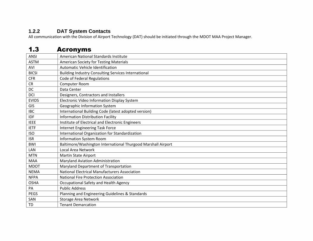
1.3 Acronyms ANSI American National Standards Institute
ASTM American Society for Testing Materials
AVI Automatic Vehicle Identification
BICSI Building Industry Consulting Services International
CFR Code of Federal Regulations
CR Computer Room
DC Data Center
DCI Designers, Contractors and Installers
EVIDS Electronic Video Information Display System
GIS Geographic Information System
IBC International Building Code (latest adopted version)
IDF Information Distribution Facility
IEEE Institute of Electrical and Electronic Engineers
IETF Internet Engineering Task Force
ISO International Organization for Standardization
ISR Information System Room
BWI Baltimore/Washington International Thurgood Marshall Airport
LAN Local Area Network
MTN Martin State Airport
MAA Maryland Aviation Administration
MDOT Maryland Department of Transportation
NEMA National Electrical Manufacturers Association
NFPA National Fire Protection Association
OSHA Occupational Safety and Health Agency
PA Public Address
PEGS Planning and Engineering Guidelines & Standards
SAN Storage Area Network
TD Tenant Demarcation

TIA/EIA Telecommunication Industries Association/Electronic Industries Alliance
UL Underwriters Laboratory
WDN Wireless Data Network

2.1 General Guidelines The overarching goals for the Division of Airport Technology (DAT) systems associated with the MDOT Maryland Aviation Administration (MDOT MAA) facilities are flexibility, reliability, and cost effectiveness. To achieve flexibility, the design of technology systems and associated infrastructure should be scalable where possible and ready for anticipated technology trends, growth, and interface with disparate systems. The design and expansion of the technology systems will be made with a clear understanding of the future of each technology. Overall reliability must be considered not only in both system redundancy but also concerning expected end of life cycles for the technology components. Finally, the technology systems must be designed and implemented within the project budget and in coordination with existing and concurrently designed system to provide a cost-effective solution. The following systems and associated infrastructure are included in the DAT Standards.
A. Communication Rooms 1. Communication Rooms 2. Equipment Closets
B. Infrastructure 1. Pathways 2. Backbone Cabling 3. Horizontal Cabling
C. Networks 1. Local Area Network (LAN) 2. Wireless Data Network (WDN)
D. Data Storage 1. Storage Area Network (SAN)
E. Workstations & Peripherals 1. Workstation Deployment 2. Printer Deployment
F. Telecommunication Systems (Under Development) 1. Telephony 2. E911

G. Radio (Under Development)
H. Operational Systems (Under Development) 1. Master Clock 2. Common Use System 3. Geographic Information System (GIS) 4. Automatic Vehicle Identification (AVI)
I. Passenger Systems (Under Development) 1. Public Address (PA) 2. Electronic Video Information Display System (EVIDS) 3. Dynamic Roadway Signage 4. Smart Park 5. Info Kiosks
J. Financial Systems (Under Development) K. Parking Revenue Control (Under Development)
2.2 Standards Systems shall be implemented as per the manufacturer’s requirements and in accordance with internationally recognized standards as well as local codes and requirements of authorities having jurisdiction, and particularly the most recent pertinent publications of the following organizations. Due to different organization publication updates, the most current published edition shall be used with any referenced industry standard. NOTE: The DAT Standards may have more stringent requirements and may differ from industry published standards. DCI is responsible for an understanding of MDOT MAA, industry standards, and DAT Standards.
MDOT MAA Maryland Department of Transportation Maryland Aviation Administration
MDOT MAA’s AIRPortal Standard
1. AIRPortal provides access and reference to the most current MDOT MAA documentation.
2. The Planning and Engineering Reference Library provide access to the most current Standard Borders, Title Blocks and Index Sheets
3. From within the MDOT MAA internal network (intranet) the URL for AIRPortal is
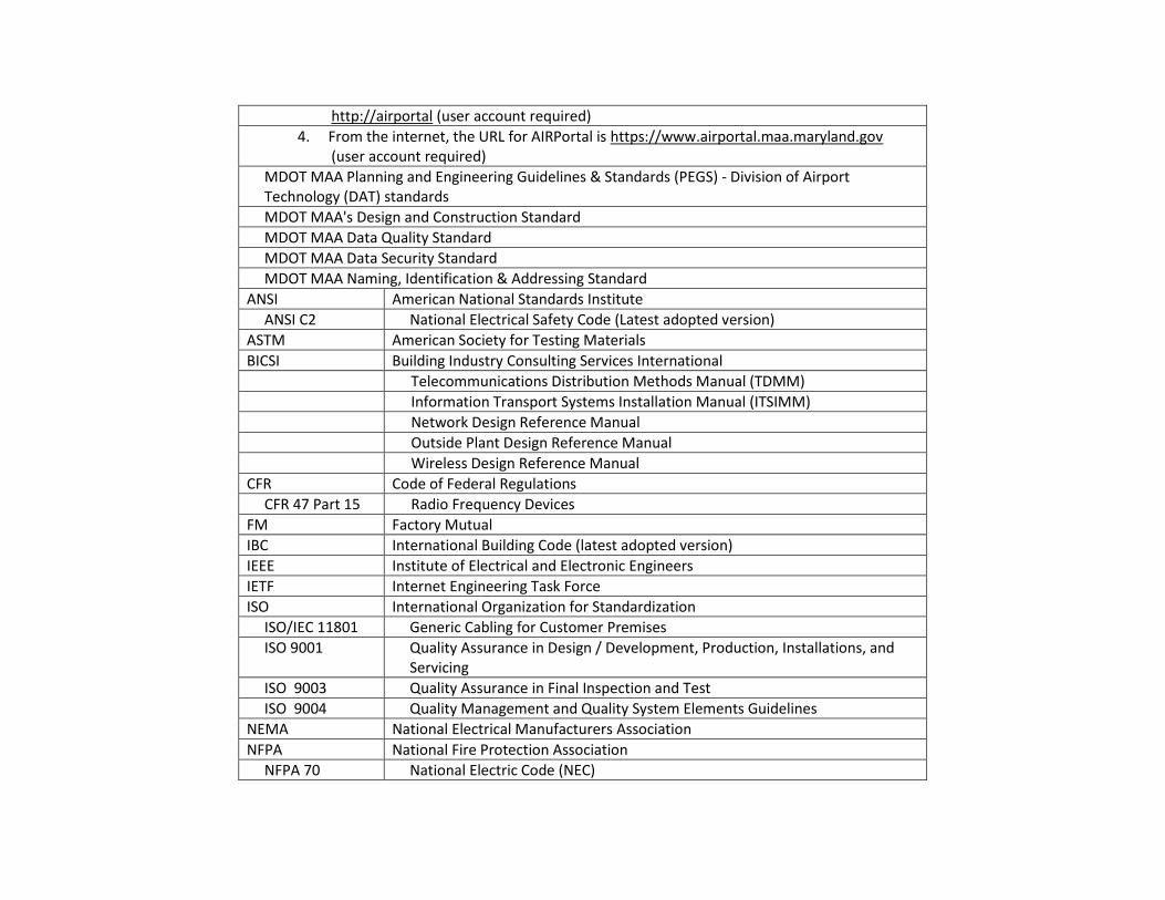
http://airportal (user account required)
4. From the internet, the URL for AIRPortal is https://www.airportal.maa.maryland.gov (user account required)
MDOT MAA Planning and Engineering Guidelines & Standards (PEGS) - Division of Airport Technology (DAT) standards
MDOT MAA's Design and Construction Standard
MDOT MAA Data Quality Standard
MDOT MAA Data Security Standard
MDOT MAA Naming, Identification & Addressing Standard
ANSI American National Standards Institute
ANSI C2 National Electrical Safety Code (Latest adopted version)
ASTM American Society for Testing Materials
BICSI Building Industry Consulting Services International
Telecommunications Distribution Methods Manual (TDMM)
Information Transport Systems Installation Manual (ITSIMM)
Network Design Reference Manual
Outside Plant Design Reference Manual
Wireless Design Reference Manual
CFR Code of Federal Regulations
CFR 47 Part 15 Radio Frequency Devices
FM Factory Mutual
IBC International Building Code (latest adopted version)
IEEE Institute of Electrical and Electronic Engineers
IETF Internet Engineering Task Force
ISO International Organization for Standardization
ISO/IEC 11801 Generic Cabling for Customer Premises
ISO 9001 Quality Assurance in Design / Development, Production, Installations, and Servicing
ISO 9003 Quality Assurance in Final Inspection and Test
ISO 9004 Quality Management and Quality System Elements Guidelines
NEMA National Electrical Manufacturers Association
NFPA National Fire Protection Association
NFPA 70 National Electric Code (NEC)

NFPA 75 Protection of Information Technology Equipment
NFPA 76 Protection of Telecommunications Facilities
NFPA 1221 Standard for the Installation, Maintenance, and Use of Emergency Services Communications Systems.
OSHA Occupational Safety and Health Agency
TIA/EIA Telecommunication Industries Association
TIA-568-B Commercial Building Telecommunications Cabling Standard
TIA-569-A Commercial Building Standard for Telecom Pathways and Spaces
TIA-606 Administration Standard for the Telecommunications Infrastructure of Commercial Buildings
TIA-607 Commercial Building Grounding/Bonding Requirements
UL Underwriters Laboratory
UL497 Standard for Protectors for Paired-Conductor Communications Circuits
All local, county, state and federal regulations and codes in effect as of date of purchase
2.2.1 Buy American – Use of Foreign Equipment DCI shall indicate in the proposal all components that may be of foreign manufacture. If any are intended to be used, DCI shall note the country of origin. Equipment of foreign manufacture must meet U.S. codes and standards.
2.2.2 Conflicts with Standards In the event of conflict between standards, guidelines, or specifications and existing field conditions, or end user requirements, the DCI shall contact the MDOT MAA Project Manager in writing (email) providing the following information:
A. Date of Discovery B. Name and Contact Information of Person Submitting C. Associated DAT Standard(s) D. Description of Conflict
This information will be forwarded to DAT by the MDOT MAA Project Manager for the final determination to resolve the conflict such as which standard takes precedence.
2.2.3 Non-Compliant Existing Technology Conditions In the event existing conditions within an area of work in the design of a new or current project does not meet the most current edition of the DAT Standards, the DCI shall contact the MDOT MAA Project Manager in writing (email). The DCI shall provide the information noted below. After coordination between the MDOT MAA Project Manager and DAT, the DCI will be notified if they are to include labor and materials to bring the area into compliance as part of the work being performed. If directed by the MDOT MAA Project Manager to include, the effort should be considered as part of the project’s scope of work and existing conditions and the required work shall be documented in project submittals. Should non-compliance be discovered during the construction of the project, the DCI shall contact the MDOT MAA Project Manager in writing (email) providing the following information:
A. Date of Discovery B. Name and Contact Information of Person Submitting C. Contract Number or Project Name D. Associated DAT Standard(s) E. Location of Conflict F. Description of Conflict G. Impact of Conflict H. Recommended Remedy
The MDOT MAA Project Manager will coordinate with DAT. The MDOT MAA Project Manager and DAT will review and determine if the non-compliance as noted by the DCI was included in the scope of work, or if the discovery is considered additional scope of work.
2.2.4 Application of DAT Standards The DAT Standards (guidelines, forms, and specifications) shall be used for all communications designs, installations and testing. Any design work or work performed as part of a contract that does not use the DAT standards along with other information provided by the Division of Airport Technology (DAT) shall be considered non-compliant and will be rejected. DAT shall review all related cut sheets, change orders, Extra Work Orders in conjunction with the designer of record if applicable. The DAT Team shall make all final determinations. Upon written agreement from DAT, the responsibility for approval of submittals may be transferred to the designer of record in conjunction with MDOT MAA Engineering & Construction. This transfer of responsibility is on a project-by-project basis. All product cut sheets approval shall occur prior to purchasing and installation by contractor.

These standards shall apply to any concessionaire tenant or Airline communications facilities installed at MDOT MAA owned properties unless a variance approved by DAT. Use of Tenant or Airline specific IT standards requires an approved variance. To obtain a variance, the DCI shall provide, in writing a request to the MDOT MAA Project Manager. Included in the variance request should be the following information:
A. Name and Contact Information of Person Submitting B. Contract Number or Project Name C. Tenant or Airline D. Variance location (plan location(s)) E. Copy of IT Standards to be used
All designs using MDOT MAA standards or coordinated variance will be rejected and be required to be resubmitted. Temporary or emergency installations may be exempt from these standards with written permission of DAT.
2.3 System Documentation During the course of a project, the necessity to obtain information related to current facilities and systems will be necessary. The following information provides the DCI with methods to obtain the information as well as document changes included in the project efforts.
2.3.1 Obtaining Record Documents Obtaining records of all existing conditions for architectural/structural as well as technology systems should be obtained from the MDOT MAA AIRPortal system (https://www.airportal.maa.maryland.gov). Assistance with the site should be coordinated with the MDOT MAA Office of Engineering and Construction. The Division of Airport Technology (DAT) can further assist with confirmation that current information has been provided for use from these sources.
2.3.2 Documentation of DAT Systems All new DAT systems and existing system revisions shall be fully documented and submitted to DAT and MDOT MAA project leadership. DCI shall coordinate with the Office of Engineering and Construction for inclusion of system documentation to the MDOT MAA AIRPortal. The DCI is responsible for complying with all MDOT MAA CAD Standards as defined in Volume 1, Chapter 3 “CAD Standards” of PEGS. Current information can be found at the following link: V1, Chapter 3 – CAD Standards. Documentation shall be compatible with the record system being maintained by MDOT MAA/DAT at the time of installation.
2.4 Qualifications of Designers, Contractors and Installers (DCI) The Division of Airport Technology (DAT) requires only qualified companies and staff to participate in the designing, installing, and maintaining technology systems at the MDOT MAA facilities. Following is an overview of these requirements. Additional information can be found in MDOT MAA Specification 270000 General Requirements for Communication Systems.
2.4.1 Company Experience As part of the MDOT MAA contract procurement process, the DCI shall submit company information associated with the provision of telecommunications systems design or construction. The submitted company shall have and submit documentation demonstrating that the company has successfully designed, built, and customer has accepted to a minimum of (3) projects of similar size, complexity and scope within the last 5-years. Upon contract award, only the submitted telecommunication system design or construction contractor may be used. Company experience requirements are applicable to all MDOT MAA owned and operated facilities.
2.4.2 Staff Experience As part of the MDOT MAA contract procurement process, the DCI shall submit staff experience information associated with the provision of telecommunications systems design or construction. Information shall be provided regarding the certification, training and experience of all key members of the project team. The project team shall include at a minimum one Registered Communication Distribution Designer (RCDD) certified by BICSI. The project team shall be identified, and resumes provided for the project team for review by DAT during the proposal evaluation process. The resumes shall include copies of all certifications and licenses required. Installers of all communications facilities shall be supervised at a minimum by a BICSI certified IT Technician, in the discipline of the work to be performed. One BICSI certified IT Technician is required for every 6 uncertified technicians.
2.5 Project Planning Considerations Inclusion of the Division of Airport of Technology (DAT) in the project planning process as early as possible is very important. Only DAT can assign or allocate communications facilities and access to those facilities. All Information Technology (IT) related projects including related support infrastructure shall be coordinated with MDOT MAA DAT. The DCI shall contact the MDOT MAA Project Manager to coordinate a meeting with MDOT MAA DAT prior to the initial submittal of the project. The project coordination shall include all MDOT MAA projects as well as all Tenant related projects. Depending on the magnitude of the project, “Break-Out Session” meetings may also be necessary. The DCI shall also coordinate this with MDOT MAA DAT Team. During the course of a project, access to the site will likely be required. DAT staff does not provide escorts for tenant services. DCI is required to coordinate with the MDOT MAA Project Manager to arrange for badging of personnel, or alternatively schedule an escort with appropriate access rights to the required project spaces. All tenant vendors shall be badged or escorted by tenant.
2.6 Reserving Existing DAT Resources Projects at MDOT MAA facilities that include a technology component require both the previously mentioned planning considerations and formal reserving of existing DAT managed resources. If the use of existing MDOT MAA resources are required, a Resource Allocation Permit must be submitted and approved by DAT prior to start of work. Without the approved permit, DAT does not guarantee resource availably and will give preference to permit holders in the event of conflict.
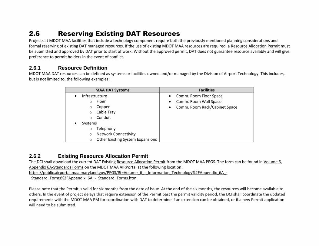
2.6.1 Resource Definition MDOT MAA DAT resources can be defined as systems or facilities owned and/or managed by the Division of Airport Technology. This includes, but is not limited to, the following examples:
MAA DAT Systems Facilities
• Infrastructure o Fiber o Copper o Cable Tray o Conduit
• Systems o Telephony o Network Connectivity o Other Existing System Expansions
• Comm. Room Floor Space
• Comm. Room Wall Space
• Comm. Room Rack/Cabinet Space
2.6.2 Existing Resource Allocation Permit The DCI shall download the current DAT Existing Resource Allocation Permit from the MDOT MAA PEGS. The form can be found in Volume 6, Appendix 6A-Standards Forms on the MDOT MAA AIRPortal at the following location: https://public.airportal.maa.maryland.gov/PEGS/#t=Volume_6_-_Information_Technology%2FAppendix_6A_-_Standard_Forms%2FAppendix_6A_-_Standard_Forms.htm. Please note that the Permit is valid for six months from the date of issue. At the end of the six months, the resources will become available to others. In the event of project delays that require extension of the Permit past the permit validity period, the DCI shall coordinate the updated requirements with the MDOT MAA PM for coordination with DAT to determine if an extension can be obtained, or if a new Permit application will need to be submitted.

2.7 Naming and Identification The Division of Airport Technology (DAT) requires consistent naming and identification of technology system components and locations at the MDOT MAA facilities. Requirements include how items are to be named as well as acceptable marking methods. Following is an overview of the items using the identification requirements:
A. Patch panels B. Device plates C. Outlets D. Cabling E. Equipment racks F. Telecommunications room(s) G. Structured cabling, including horizontal and backbone cabling H. Communications cabling cross-connects I. Communications backboards J. Life Safety and Security Systems K. Grounding and Bonding System
The DCI is responsible for review of detailed information found in MDOT MAA Specification 270553 Identification on the MDOT MAA AIRPortal.
2.7.1 Facility Warning Label Examples Following are examples of the Facilities Warning Labels to be used for permanent marking of inside plant conduits 1” and above, junction boxes, and enclosures. See MDOT MAA Specification 270553 Identification, Part 5 for detailed information.
A. Telecommunications System: Green and Yellow

1. Copper Plant: Green and Yellow
2. Fiber Optics Plant: Green and Orange

3. Emergency Paging System: Green and Red
4. Data Networks: Green and Black

5. IASS Plant: Green and Purple
6. Flight Information Display System (FIDS) Plant: Green and White

7. Common Use Terminal Equipment (CUTE) Plant: Green and Grey
8. Building Automation Plant: Green and Brown

9. Radio/RF Networks: Yellow and Orange
2.8 General Warranty Requirements The Division of Airport Technology (DAT) general warranty requirements align with the MDOT Maryland Aviation Administration’s (MDOT MAA) requirements. Detailed information regarding warranty information can be found in the MDOT MAA’s General and Special Provisions Document. This document is also referenced in the MDOT MAA Specification 270000 General Requirements for Communication Systems, Section 1.8.
2.9 Approved Products The Division of Airport Technology (DAT) has reviewed market offering and specified technology products for use in DAT systems. The available and/or Basis of Design product manufacturers are listed in each associated specification section, as available on the MDOT MAA AirPortal, to direct the DCI to acceptable solutions. For proprietary systems, DCI is responsible for review and use of the identified products. These products have been proven at the MDOT MAA based on established product performance, appearance, installation means and methods and with input from subject matter experts, installers, and system maintenance providers. This list is for major components and assemblies. Incidental products shall follow industry standards and best business practices established by the MDOT MAA where applicable.

Only available and/or Basis of Design products as listed in the specifications shall be used. Functional equivalents and approved equals will NOT be allowed without DAT approval. DCIs wishing to have alternative products considered for use may follow the instruction provided for “Equal or Approved Equal” or “Substitutions” as found in Section 5 of the Special Provisions.
2.10 DAT Typical Details The Division of Airport Technology (DAT) has developed a set of typical details for use by the DCI. The following detail types can be found in Appendix 6C, Concept Drawings:
1. Typical Telecommunication Rooms 2. Typical Demarcation Cabinets 3. Typical Cable Tray Installation Details 4. Typical Containment Penetration Details 5. Typical Date Outlet Details 6. Typical Grounding Details 7. Typical Display Mounting Details 8. Typical Emergency Call Box Details 9. Typical Public Address Speaker & Ambient Noise Sensor Details 10. Typical Common Use Equipment Details
The DCI is responsible for the review and implementation of these design principles. Any deviation from the depicted concepts must be approved in writing by DAT.
3.1 Communication Room Introduction The Division of Airport Technology (DAT) has established a system of communication rooms throughout the MDOT Maryland Aviation Administration’s (MDOT MAA) facilities. These rooms house telecommunication and security system equipment and serve as a termination and distribution point for incoming telecommunication services to the building, and serve as a common distribution point for cables to other Communications Rooms or user locations. Following are definitions and requirements for the types of Communication Rooms in use a MDOT MAA facilities. In the case that current Communication Rooms do not meet or exceed the noted requirements, the DCI shall coordinate with DAT to determine acceptable modifications.
3.1.1 Definitions A. Building Entrance Room (BER) is defined as a room serving as the primary entry for MDOT MAA site infrastructure and
telecommunication service provider cabling.
B. Data Center (DC) is defined as a room or facility serving to house MDOT MAA primary and secondary system headend servers and equipment for communications services and systems that serve a critical function at BWI Marshall.
C. Computer Room (CR) is defined as communication room serving to house MDOT MAA servers and/or equipment specific for operational requirements of the nearby areas or as the primary room for a remote facility on the BWI Marshall campus. CRs also serve as distribution rooms for horizontal cabling requirements. Computer Rooms may have other airline or tenant equipment.
D. Telecommunication Room (TR) is defined as a communication room serving as a local distribution point for communication services to nearby spaces. Telecommunication Rooms may have other airline or tenant equipment.
E. Extended Tenant Demarcation (TD) is defined as a demarcation location that serves to extend communications facilities from a TR to a tenant’s or Airline’s leased space for connection to the MDOT MAA network, MDOT MAA Emergency Paging, PSN, or other communications providers.
3.1.2 Communication Room Identification All facilities shall be documented and referenced by the door number. DAT does not recognize room numbers in official records. See Section 2.9 for additional identification information.
3.1.3 Communication Room Typical Layouts Typical Communication Room layouts have been developed for use by the DCI. See Appendix 6C, Section 1 for example configurations. Any deviations from the depicted concepts must be approved in writing by DAT.
3.2 Requirements for All Communication Room Types 3.2.1 Architectural Requirements for Communication Rooms 3.2.1.1 Configuration A. All Communication Rooms shall be rectangular in shape length. Provision of L-Shaped or other irregular shapes is not acceptable. Room shall
have no obstructions, structural columns, or other equipment that infringes on the minimum dimensions noted for each Communication Room type.
B. The final size of the room will depend on the quantity of racks/cabinets and other equipment associated with systems. Future growth shall also be factored into the final size of the room without the need for moving existing equipment. BISCI TDMM room sizing guidelines coupled with the below noted clearance requirements are to be used as a basis for development of communication room requirements. Deviation from these guidelines must be approved by MDOT MAA DAT.
C. Clearance Requirements - Room size and layout must allow for the following clearances. Clearance may be shared between wall mounted and rack or cabinet devices but must accommodate the greater of the two clearance requirements. 1. 3’ clearance behind furthest protruding, rack mounted equipment or cabinet back to nearest item or structure. 2. 4’ clearance in front of face of rack mounted equipment or cabinet front to nearest item or structure. 3. 3’ clearance in front of face of wall mounted equipment to nearest item or structure. For sizing purposes, wall mounted equipment shall
be assumed to be 12” in depth. 4. Minimum 3’ clearance between rows of equipment or cabinet backs and rack or cabinet faces.
3.2.1.2 Walls A. Provide fire rated partitions between structural floor and ceiling for physical security and fire protection. Fire rating of partitions shall be as
required per NFPA. B. A minimum of two walls shall be provided with 3/4” FRT (Fire Retardant Treated) grade plywood. Paint requirements shall be the same as
requirements for the walls. Plywood to be painted on all six sides prior to mounting. No infrastructure or element shall be mounted directly to any wall. DCI to ensure fire rating marking is not obscured in one location on each piece of plywood, and fire rating marking shall be visible when plywood is mounted.
C. Wall surfaces to be painted with 2 coats of light-colored paint to enhance lighting and must be applied before room fit out. Paint shall be off-white/egg shell color; coordinate paint color (RAL number or AMS-STD-595 color) with MDOT MAA.
3.2.1.3 Flooring A. The flooring shall have electrostatic-safe vinyl tile. An exception to this requirement is the use of a raised floor.

B. Tile shall be placed before the setting of racks and other equipment. C. The tile shall be cleaned and waxed after the installation of all equipment and prior to final acceptance.
3.2.1.4 Ceiling A. No suspended ceiling will be installed in Telecommunication Rooms. If possible, room shall be open to structure above. B. Ceiling surfaces to be painted with 2 coats of light-colored paint to enhance lighting and must be applied before room fit out. Coordinate
paint color (RAL number or AMS-STD-595 color) with MDOT MAA.
3.2.1.5 Entry A. Entry door size is dependent upon type of communication room. See room specific details in Sections 3.3, 3.4, 3.5, and 3.6. B. The door shall be a metal, hollow door, fire rated in accordance with NFPA. C. Doors shall be a lockable outward-opening door. D. Access Control Devices shall be provided for all Communications Rooms including card reader with PIN pad for entry, door position switch,
electrified locking means, and Request to Exit device. DCI shall coordinate security requirements based upon PEGS Volume 7 Safety and Security and Office of Airport Security requirements.
3.2.1.6 Penetrations A. All penetrations of fire rated walls shall be fire stopped in an approved manner to prevent the passage of flames, smoke, and fumes. B. Installation of firestopping shall be performed by an installer trained and certified by the product manufacturer. C. When trays intersect with walls or other fire-rated barriers they shall employ the use of re-enterable and re-useable Fire Stopping. The uses
of fiberglass insulations, putties, caulks, pillows, or foams are not approved for this purpose.
3.2.1.7 Glazing No windows are allowed in Communication Rooms.
3.2.2 Electrical Requirements 3.2.2.1 Lighting A. Lighting shall be limited to the use of LED 4-foot industrial style light fixtures as identified in PEGS V2, Chapter 12, Section 12.1 Interior
Lighting. B. Lighting shall be controlled via a light switch at each exit. No motion sensor or dimmer type switch shall be allowed, only manual toggle light
switches shall be allowed. C. The design luminance shall be a minimum of 500 lux in the horizontal plane and 200 lux in the vertical plane, measured 1 m (3 ft) above the
finished floor in the middle of all aisles between cabinets and racks. Lighting shall be designed and installed to provide maximum coverage in front and behind equipment.
D. Suspend all light fixtures from a UL listed strut-type channel raceway. E. Lighting shall be installed in accordance with MDOT MAA electrical and lighting standards.
3.2.2.2 Power A. Power Routing
1. Power and communications cables shall maintain a 3-foot separation to the greatest extent possible. Where the separation cannot be maintained, minimize parallel runs. Refer to Specification 270528 Pathways for Communication Systems, Clearances, for further information.
2. In the event that communication and power cables must cross, the crossing must be at a 90° angle. B. Electrical Panel Boards
1. Electrical panel boards shall not be located within Communications Rooms except when required by code. 2. Where necessary, panel boards shall be dedicated to loads within the Communications Room only and shall be located to minimize
electromagnetic interference. All panel boards if required will be “Clustered” within the room to reduce overall clearance requirements. C. Room Power
1. The electrical circuits supporting all telecommunication rooms shall be generator-backed circuits (where available). 2. Commercial power (dedicated 20A/120V circuit) duplex outlet shall be provided to duplex convenience receptacles serving the
Communications Rooms spaced 12’ apart on walls at 12” above floor finish (AFF) to bottom of receptacles. The receptacles shall be accessible at all times and not be blocked by racks, cabinets or other equipment. Convenience outlets shall be for general maintenance purposes and communication equipment shall not be connected to these circuits.
3. Power receptacles are to be labeled with circuit number, panel numbers and receptacle type in a permanent manner per MDOT MAA standards.
4. Communication Rooms shall be provided with a 30A/208V normal power twist lock receptacle(s) capable of supporting an emergency cooling unit. Confirm location and requirement with DAT.
5. Communication rooms shall be provided with outlets to support UPS units. Coordinate outlet type with UPS to be provided. UPS power circuits shall be provided from generator/Emergency power circuits (where available) and as noted below as part of the Cabinet and Rack Power requirements.
D. Cabinet and Rack Power
1. All power and communications to racks and cabinets shall be top fed when raised flooring is not present. 2. The availability of generator power varies between communication rooms, with some rooms having generator power available and
other rooms not having it available. Provide commercial, generator, and UPS power as follows:
a) For Telecommunication Rooms (TR), Computer Rooms (CR), and/or Building Entrance Rooms (BER) that do not have generator power available, provide each rack or cabinet two (2) 110V 30-amp twist lock receptacles above each location, one fed from commercial power, and the second from a UPS that is connected to commercial power.
b) For Telecommunication Rooms (TR), Computer Rooms (CR), and/or Building Entrance Rooms (BER) that do have generator power available, provide each rack or cabinet two (2) 110V 30-amp twist lock receptacles above each location, one fed from generator power, and the second from a UPS that is connected to generator power.
c) For Data Center (DC) spaces, these spaces are expected to have generator power available and a centralized, whole room UPS should be provided. For these rooms, provide each rack or cabinet two (2) 110V 30-amp twist lock receptacles above each location, both fed from the centralized UPS that is connected to generator power. If redundant UPS units are provided, provide each rack or cabinet should with a receptacle connected to each UPS unit.
3. Where raised flooring is present, all communications cables shall be routed in overhead cable tray and transitioned to cabinets/racks via waterfall fittings; all electrical circuits shall be routed through the below-floor space and routed through the bottom of the cabinet/rack.
4. Power Distribution Unit with circuit protection: Each rack/cabinet containing powered equipment shall have two independent Power Distribution Units (PDU) installed. For strip type PDUs to be mounted vertically, provide one on each side. a) The commercial power PDU shall be on the right side (facing from rear) and will be dedicated to commercial power. The PDU shall
have sufficient outlets to provide service to the entire fully populated rack. b) The UPS PDU shall be on the left side (facing from rear) shall be delineated as UPS either with orange receptacles or permanently
marked “UPS POWER”. Coordinate UPS PDU with available outputs on the provided UPS if rack mounted UPS units are provided. 5. The minimum power requirements for each equipment PDU shall be 30A/120V (except as required to match the rack mounted UPS
outputs). 6. DCI will coordinate with DAT and the electrician for final connections 7. Transformers
a) Transformers shall not be located within Communications Rooms. Where necessary, transformers shall be dedicated to loads within the Communications Room only and shall be located to minimize electromagnetic interference.
b) Transformers that provide power for communication rooms shall have a Faraday Shield installed to further improve noise immunity and be K-rated to accommodate non-linear loads. As an alternative, the transformer can use harmonic canceling techniques to mitigate the effects of harmonics.
E. UPS Power
1. The purpose of the UPS is not to provide power during power outages. The primary function is to provide power filtering and to provide 15 minutes of backup power, so the system can be shut down in a regulated fashion.
2. UPS units will be required to manage transitions to emergency power. 3. A central UPS system may be considered in lieu of individual rack-mounted UPS devices.

4. All MAA systems requiring A/C power in shall be provided with an uninterruptible power system (UPS). The UPS inverter shall be sized to accommodate growth of the load, with the inverter sized to accommodate the calculated load plus a spare capacity of 100% (inverter shall be sized for double the calculated load). The batteries shall be sized for a run time of 15 minutes, and shall be expandable by adding batteries to provide not less than 15 minutes of run time at maximum inverter loading.
5. Minimum size of floor mount UPS units shall be 20 kVA, minimum size of rack mount units shall be 1400 VA. Floor units shall be equipped with a Battery Cabinet and Emergency Bypass Cabinet. Output panel board for UPS power distribution should be in the communication room.
6. The UPS shall be provided with (1) network interface cards for Simple Network Management Protocol (SNMP) connection for DAT monitoring. The UPS shall also be provided with (1) network interface card and components for the Building Automation System (BAS) connection, compatible with the Johnson Controls’ Metasys System.
3.2.3 Telecommunications Requirements 3.2.3.1 Telecom Outlets A. A wall mounted phone and all associated wiring shall be installed 48-inches above the finished floor located near the primary entrance/exit. B. A minimum of one data outlet shall be located on each wall. Outlets shall be wall mounted, aligned and adjacent to electrical outlets.
Mounting height to be as indicated in drawings.
3.2.3.2 Backbone Connectivity A. Fiber and copper connectivity shall be provided from two diverse locations for reliability and redundancy. B. Connection locations and cabling quantities shall be coordinated with DAT.
3.2.3.3 Raceways and Supports A. A ladder style cable tray system shall be installed around the entire perimeter of the room and routed above each equipment rack/cabinet. B. There shall be NO basket Cable Tray installed in any Communications Room. The type of cable system shall be ladder rack style as required
per the communication room equipment specification. C. A 4”x4” Yellow Fiber Duct shall be provided above the Ladder Racks between Racks or Cabinets to allow patching. D. The mounting height of cable tray and fiber duct shall be a minimum of 12-inches above the racks and shall be supported per manufacturer
recommendations. E. Conduits from floor and wall entrances shall be 4” in diameter, labeled where they originate, and fire stopped with approved fire stop
assembly.
3.2.3.4 Communication Media (Fiber and Copper) A. All cabling shall be installed and properly dressed and labeled to present a professional and workmanlike installation. B. All cabling shall be in cable tray.

C. No unsupported cabling length greater than two feet (2’) shall be permitted. D. All terminations, patch panels, splices (where allowed), and blocks must be installed, dressed and labeled in a neat order.
3.2.3.5 Cabinets and Racks A. Communication Rooms shall be fitted with open frame racks or freestanding, enclosed equipment cabinets (per Specification 271123
Telecommunication Room Equipment) to support required equipment. B. Freestanding, enclosed equipment cabinets shall be used for all security related equipment such as patch panels, switches, servers, and rack
mounted UPS units. C. Open frame racks shall be used for non-security devices such as switches, patch panels, system equipment, and rack-mounted UPS. D. Horizontal and vertical cable management shall be provided for all cabinets and racks.
3.2.3.6 Ground and Bonding A. All grounding and bonding shall be per code requirements. B. Additional Grounding & Bonding information can be found in DAT Specification 270526. C. All Racks and Ladder trays shall be grounded to the TMGB or TGB depending on the room type.
3.2.4 Mechanical Requirements 3.2.4.1 Function A. The environmental control system shall be designed to function properly for 24/7 operations. B. The system shall be designed to operate under positive pressure with respect to its surroundings with a minimum of one air change per
hour. C. Maintain temperatures within the Communication Rooms at 64° to 75° F. D. A fire damper shall be provided to maintain the room’s 2-hour fire rating (if applicable). E. See additional requirements for Data Centers and Computer Rooms in the associated sections. F. Humidity Control - Equipment shall be sized and provided to maintain a relative humidity from 30% to 55%.
3.2.4.2 Equipment Selection A. The equipment shall be sized and dedicated for the room it serves to maintain temperatures not to exceed 75-degrees F. B. The design of the environmental control system shall be based on ultimate requirements of the space. The design shall account for a fully
built out and populated communication room, not the initial installation. Example if 3 rack/cabinets are installed but the room is designed to accommodate up to 5 racks/cabinets, the HVAC shall be sized for 5 racks/cabinets and the associated active equipment expected to be installed should all of the cabinets be fully populated. The environmental control system for a communication room shall be dedicated to the communication room.

3.2.4.3 Equipment Location A. Mechanical equipment shall be located outside of, but adjacent to, the room. This will reduce the possibilities of condensate water entering
the racks/equipment. B. However, in the event that equipment is approved by DAT to be located inside the room, drip pans and condensate pumps shall be provided
to shield equipment from potential water damage. Approval will require a room of sufficient size that the mechanical equipment remains accessible and is not located above equipment or reserved spare space.
C. All temperature sensors and controls shall be located within the room the HVAC equipment serves and at no more than 5-feet above the finished floor.
3.2.5 Fire Protection 3.2.5.1 Monitoring and Detection Smoke detection shall be provided within the Communication Rooms.
3.2.5.2 Fire Suppression A. See Fire Suppression requirements associated with each Communication Room type. Refer to MDOT MAA PEGS V3 Life Safety and NFPA 75
and 76 (latest adopted version). B. To determine the appropriate fire protection approach, reference Figure A.1.3 Decision Tree for Application of NFPA 75 and V6, Section
4.1.1.
3.2.6 Fire Suppression A. Critical Communication Rooms shall be provided with special agent suppression systems. Critical communication rooms are defined as the
Data Center and the existing Main Telephone Rooms. In addition, rooms with emergency paging system equipment or emergency communication equipment may be considered for special agent suppression systems as deemed appropriate by the AHJ and DAT.
B. All Building Entrance Rooms, Computer Rooms, and Telecommunication Rooms shall be equipped with fire suppression systems as required in MDOT MAA PEGS V3, Life Safety and NFPA 75 and 76 (latest adopted version).
C. Pre-Action Fire Sprinkler System or Special Agent Suppression System: Should a pre-action fire sprinkler system or special agent suppression system be required for a Data Center, Building Entrance Room, Computer Room, or Telecommunication Room, the following shall apply: 1. Pre-action fire sprinkler systems employ the basic concept of a dry pipe system in that water is not normally contained within the pipes.
The water is withheld from the piping by an electrically operated valve, known as a pre-action valve. Valve operation is controlled by independent flame, heat, or smoke detection. Two separate events must happen to initiate sprinkler discharge. First, the detection system must identify a developing fire and then open the pre-action valve. This allows water to flow into system piping, which effectively creates a wet pipe sprinkler system. Second, individual sprinkler heads must release to permit water flow onto the fire. The system shall

be sized and configured per all applicable codes and requirements. Alternatively, a Special Agent Suppression System may be selected for use. Requirements for the system shall align with those noted in the Computer Room requirements. The DCI shall coordinate the use of a pre-action system or special agent suppression system with DAT.
2. Pre-Action Fire Control Panel shall not be installed in the room that it serves; the location of the Pre-Action Fire Control Panel shall be in a nearby room.
3. A Fire Marshal approved monitoring module and smoke detector shall be installed at the location of the Pre-Action Fire Alarm Control Panel or Special Agent Suppression System Control Panel that protects the Communications Room(s). The control panel shall monitor the pre-action or special agent suppression system for any supervisory, trouble, or alarm signals. At a minimum, the control panel shall provide dry contact outputs for supervisory, trouble, and alarm signals that tie into a fire alarm module for the overall area or building fire alarm panel. These signals shall annunciate on the fire alarm control panel and on the UL listed fire alarm workstation(s) for the fire alarm system.
D. The existing Telecommunication Rooms have a mix of fire suppression systems that may not align with the current MDOT MAA standards. For rooms that are being revised, expanded, or undergoing major renovation that impacts over 50% of the existing room floor space or increase the room floor space by over 25% of the existing area, the fire suppression system shall be brought into alignment with the current MDOT MAA standards and in accordance with the direction of the AHJ. In addition, for existing suppression systems that have reached end-of-life and require major refurbishment or replacement, the suppression system shall be brought into alignment with the current MDOT MAA standards and in accordance with the direction of the AHJ.
E. Any existing Telecommunication Rooms that are being renovated that does not current have smoke detection shall be provided with smoke detection as part of the renovation.
3.3 Additional Requirements for Building Entrance Rooms Each Building Entrance Room (BER) shall meet the requirements as noted in the “Requirements for All Communication Rooms”. The following requirements are in addition to previously noted.
3.3.1 Size A. BERs shall be of sufficient size to accommodate, at a minimum, four 42 Rack-Unit (RU) high by 19 inches wide approved equipment racks.
Communication Devices may be housed in open frame racks and on the BER walls as allowed by MDOT MAA DAT B. Room shall be sized to accommodate required number of racks or cabinets plus space allocated for one additional, future rack or cabinet,
plus adequate wall space for any MDOT MAA allowed wall-mounted equipment.
3.3.2 Entry The single BER entry door shall comply with general requirements and have a minimum size of 36” wide and not less than 80” in height.
3.3.3 Backbone Cabling High Density Protection Field - A high density protection field shall be required on all copper OSP facilities entering the room when exiting the splice case, the copper cabling shall be routed to a high-density protector frame using stub cables. The protector frame shall be located as close to the entry point as feasible and adjacent to the splice case. Distribution stub cables shall be extended from the protector frame to the main distribution frame.
3.3.4 UPS Power A. All MAA DAT systems within the BER requiring A/C power in shall be provided with an uninterruptible power system (UPS). The UPS inverter
shall be sized to accommodate growth of the load, with the inverter sized to accommodate the calculated load plus a spare capacity of 100% (inverter shall be sized for double the calculated load). The batteries shall be sized for a run time of 15 minutes, and shall be expandable by adding batteries to provide not less than 15 minutes of run time at maximum inverter loading.
B. BER shall be equipped with UPS units with a minimum size of 1400 VA, but should larger units be required, the UPS may be floor mounted if in excess of 6 KVA.
3.4 Additional Requirements for Data Centers (DC) Each Data Center Room shall meet the requirements as noted in the “Requirements for All Communication Rooms”. The following requirements are in addition to previously noted.
3.4.1 Raised Floor A. Data Centers shall have raised floor throughout the space. B. Transitions from finished floor level to raised floor level shall occur outside of the calculated Data Center size requirement.
3.4.2 Size A. Additionally, Data Centers shall be of sufficient size to accommodate the following minimum, ten 42 Rack-Unit (RU) high by 19 inches wide
approved equipment cabinets or racks. All servers shall be housed in free-standing enclosed equipment cabinets. Non-server devices may be housed in open frame racks.
B. Room shall be sized to accommodate required number of racks or cabinets plus space allocated to accommodate additional racks or cabinets. The room shall be sized to provide 20% spare racks or cabinets, but not less than one. For example, a ten rack/cabinet room would be sized to accommodate two additional racks or cabinets, while a twenty rack/cabinet room would be sized to accommodate four additional racks or cabinets. For all DC rooms, the room should be sized to accommodate a minimum of two additional, future racks or
cabinets.
3.4.3 Entry The double Data Center entry door shall comply with general requirements and have a minimum size of 72” wide.
3.4.4 UPS Power A. Data Centers shall utilize a central UPS system rather than individual rack-mounted UPS devices. B. All systems requiring A/C power in shall be provided with an uninterruptible power system (UPS). The UPS inverter shall be sized to
accommodate growth of the load, with the inverter sized to accommodate the calculated load plus a spare capacity of 100% (inverter shall be sized for double the calculated load). The batteries shall be sized for a run time of 15 minutes, and shall be expandable by adding batteries to provide not less than 15 minutes of run time at maximum inverter loading.
C. Minimum size of floor mount UPS units shall be 20 kVA. D. Floor units shall be equipped with a Battery Cabinet and Emergency Bypass Cabinet. Output panel board for UPS power distribution should
be in the Data Center. E. Data Center UPS unit power shall be provided from emergency/generator power sources.
3.4.5 Mechanical For the Data Centers, in addition to the requirements mentioned previously in the communications room section, a dual/redundant HVAC system shall be provided.
3.4.6 Fire Suppression A. Data Centers shall be provided with a Special Agent Suppression System that fully complies with NFPA (most current edition). A Clean Agent
Fire Extinguishing System releases inert gas or chemicals stored in containers to extinguish detected fires and also includes smoke detection. This system uses no water and leaves little to no residue.
B. A Special Agent Suppression system will also require a separate room to house the system. The Data Center served by the Special Agent Suppression system shall be fire-stopped and sealed per the system requirement. The DCI shall coordinate with MDOT MAA DAT on the need for a Special Agent Suppression system.
C. A Fire Marshal approved monitoring module and smoke detector shall be installed at the location of the Special Agent Suppression Fire Alarm Control Panel for monitoring by the MDOT MAA Fire Alarm System.
D. Data Centers that have existing Suppression Agent Suppression Systems or Communications rooms that will have Clean Agent Fire Extinguishing Systems shall fully comply with NFPA (most current edition). This includes any new work in the rooms impacting sizing requirements and enclosure inspections. Example: running a new conduit, pipe etc. through the space. Smoke/pressure leakage testing in accordance with NFPA Standard for Special Agent Suppression Systems shall be required to check all work and that room sealing integrity has been maintained.
3.5 Additional Requirements for Computer Rooms (CR) Each Computer Room shall meet the requirements as noted in the “Requirements for All Communication Rooms”. The following requirements are in addition to previously noted.
3.5.1 Size A. CRs shall be of sufficient size to accommodate the following at a minimum, four 42 Rack-Unit (RU) by 19 inches wide approved equipment
cabinets or racks. All servers shall be housed in free-standing enclosed equipment cabinets. Non-server devices may be housed in open frame racks.
B. Room shall be sized to accommodate required number of racks or cabinets plus space allocated for one additional, future rack or cabinet.
3.5.2 Entry The single CR entry door shall comply with general requirements and have a minimum size of 36” wide.
3.5.3 UPS Power A. All MDOT MAA systems within the Computer Room requiring A/C power in shall be provided with an uninterruptible power system (UPS).
The UPS inverter shall be sized to accommodate growth of the load, with the inverter sized to accommodate the calculated load plus a spare capacity of 100% (inverter shall be sized for double the calculated load). The batteries shall be sized for a run time of 15 minutes, and shall be expandable by adding batteries to provide not less than 15 minutes of run time at maximum inverter loading. If non-MDOT MAA equipment is to be installed in the CR, coordinate if the non-MDOT MAA equipment loads are to be included in the UPS sizing or if an additional UPS is required to be provided by the equipment owner.
B. CRs shall be equipped with rack mount units with a minimum size of 1400 VA.
3.6 Additional Requirements for Telecommunication Rooms (TR) Each Telecommunication Room shall meet the requirements as noted in the “Requirements for All Communication Rooms”. The following requirements are in addition to previously noted.
3.6.1 Location A. Telecommunication Rooms (TRs) should be located so that all service drops or outlet services cable within the area served by the closet are
not in excess of 90 meters in length. The total circuit length shall not exceed 100 meters, which includes station cabling and patch cords at the Communications Room and outlet ends.
B. TRs should be stacked vertically floor-to-floor with connecting sleeves for backbone distribution. If rooms cannot be stacked, then additional pathway and interconnections between the rooms may be required. Coordinate room locations and requirements with DAT.
C. TRs should not be located below restrooms, plumbing chases, kitchen areas, pet relief areas, or other areas that would require supply or wastewater piping to be routed through or above the TR.
3.6.2 Size A. TRs shall be of sufficient size to accommodate the following at a minimum, two 42 Rack-Unit (RU) by 19 inches wide approved equipment
racks. B. Room shall be sized to accommodate required number of racks plus space allocated for one additional, future rack.
3.6.3 Entry The single TR entry door shall comply with general requirements and have a minimum size of 36” wide.
3.6.4 UPS Power A. All systems within the TR requiring A/C power in shall be provided with an uninterruptible power system (UPS). The UPS shall be sized to
accommodate calculated load plus 200% with run time of 15 minutes. B. TR shall be equipped with rack mount units with a minimum size of 1400 VA.
3.7 TSA, CBP, and Other Special Requirement Communication Rooms In addition to MDOT MAA communication rooms throughout the airport, there are also other communication rooms that may have specific requirements above and beyond the requirements listed above. Government agencies such as the Transportation Security Administration (TSA) and Customs and Border Protection (CBP) have specific requirements for their communication rooms. Refer to the TSA Checkpoint Requirements and Planning Guide (CPRG) (latest version) and Planning Guidelines and Design standards for Checked Baggage Inspection Systems (PGDS CBIS) (latest version) for any additional TSA requirements. Refer to U.S. Customs and Border Protection (CBP) Airport Technical Design Standard (ATDS) (latest version) for any additional CBP requirements. The CBP ATDS is a restricted document that is labeled For Official Use Only (FOUO) and is not available in the public domain. The CBP ATDS document may be requested from CBP for projects that are deemed to require the document and demonstrate a valid “need-to-know.”
3.8 Tenant Demarcation (TD) Requirements The Tenant Demarcation (TD) is an enclosure that will be placed within or adjacent to a tenant space. The TD is expected to be a cabling interconnection point only and will not contain any active equipment. The TD shall include the following:
A. An enclosure that will be sized per the cabling to be installed, but not less than 24” x 24” x 8” deep. Cabinet shall be provided with a removable back panel to allow mounting of equipment within the enclosure.
B. Cabinet shall be provided with a lock and padlock hasp to allow for the MDOT MAA to secure the cabinet. Coordinate padlock with MDOT MAA DAT.

C. The cabinet shall be mounted in the ceiling or on a wall location as coordinated with MDOT MAA DAT. Cabinet shall be located so that cabinet will remain accessible and be protected from damage. The location shall account for possible changes in tenants.
D. The TD cabinet shall be connected back to the nearest TR or CR and shall provide conduit and cabling. Cabling shall include the following: 1. Option 1. For Tenant Areas (Airlines, TSA etc.): Conduit size shall be sized with a 40% fill ratio, but not less than 2”, and include the
following: a) (1) 50 pair Unshielded Twisted Pair (UTP) CAT 3 Copper b) (1) 12 strand Single Mode Fiber cable unless specified c) (1) RG 11 coaxial cable (refer to 270101-TC) d) (1) E-page speaker facility (refer to 275116 – Public Address/Emergency Communication System) e) (1) page shunt trip facility (refer to 275116 – Public Address/Emergency Communication System) f) (Contact the PDS Administrator for location)
2. Option 2. For Concessions Area: Conduit size shall be sized with a 40% fill ratio and shall include the following:
a) (2) 4 pair Unshielded Twisted Pair (UTP) CAT 6 Copper Cable b) (1) 6 strand Single Mode Fiber cable (unless noted otherwise on the drawings) c) (1) RG 11 coaxial cable (refer to 270101-TC) d) (1) E-page speaker facility (refer 275116 – Public Address/Emergency Communication System) e) (1) E-page shunt trip facility (refer to 275116 – Public Address/Emergency Communication System) f) (Contact the PDS Administrator for location)
E. Typical Communication Room layouts have been developed for use by the DCI. See Appendix 6C, Section 2 for example configurations. Any deviation from the depicted concepts must be approved in writing by DAT.
3.9 MDOT MAA Communication Room Prohibited Items MDOT MAA Communication Rooms (including Equipment Closets) are for the exclusive use of MDOT MAA/DAT. No tenant or MDOT MAA contractor is to install equipment, frames, or electronics in these rooms without written permission from DAT. The following may not be located in, or travel through an MDOT MAA Communication Room.
A. Non-communications electrical distribution equipment, custodial supplies, transformers, or other equipment that is not specific to the room. Additionally, no baggage systems equipment, electrical distribution conduits, or large HVAC ducts or piping unassociated with the communication room shall be allowed to be run through the room.
B. Lightning Protection: Down conductors or grounding components not associated with the communication room grounding shall not be present within the communication room.
C. Equipment: Any Tenant or MDOT MAA hardware, electronic equipment, wiring or racks that have not been approved by DAT. D. Electronic Noise Emitters: Any equipment that emits EMI/EMF. Certification by the manufacturer shall be required.
E. Water, waste or drain lines: The installation in, through or above the room. In the event approval is sought and granted, DCI shall restrict routing of water, waste water, drain lines. through communications Room(s)and communication rooms may not be located below restrooms or plumbing chase areas. In no event shall the routing of water lines be over electronic equipment or racks.
3.10 Communication Room Drawings Communication Rooms must be fully and accurately documented from design drawings through the submission of as-built documentation. The drawings shall show all systems within the Communications Room, coordinated with each other and shown on a composite drawing (Coordinated Drawing). The composite drawing will have related elevations, sections and plan views to validate coordination. In addition, the composite drawing shall show all floor and wall penetrations. Additionally, the composite drawing shall also show at a minimum (2) adjacent rooms in all directions including floor above and floor below and shall show its location on a terminal plan.
4.1 Infrastructure Introduction MDOT MAA facilities will be designed based upon the objective of creating and maintaining a modern, secure, and efficient airport environment.
Technology has become one of the most valuable business enablers to create such environment, as it permeates every aspect of airport
communications, operations, and security. A properly planned technology environment provides reliable systems that reduce costs and provide
enhanced services to airlines and passengers as well as operational efficiency and enhanced safety and security. The Structured Cabling System
(SCS) provides the infrastructure to accomplish this. The intent is to create and maintain systems that are capable of adapting to change with
minimal disruption to the operating facilities. Equipment will be standardized to the greatest extent possible to simplify long term maintenance
and operations. The structured cabling system is defined as all components required to provide a complete and end to end cabling
infrastructure. The provision shall include all hardware, termination blocks, patch panels, telecommunications outlets, telecommunication
cabling, and containment.
Refer to the following specifications for additional information regarding infrastructure requirements
A. 270000 General Requirements for Communication Systems
B. 270526 Grounding and Bonding for Communication Systems
C. 270528 Pathways for Communication Systems
D. 270536 Cable Trays for Communication Systems
E. 270553 Identification
F. 271123 Telecommunications Room Equipment
G. 271300 Backbone Cabling
H. 271400 Outside Plant Cabling
I. 271500 Horizontal Cabling
J. 271600 Telecommunications Station Equipment
K. 272100 Data Communications Network Equipment
L. 275116 Public Address Emergency Communications System
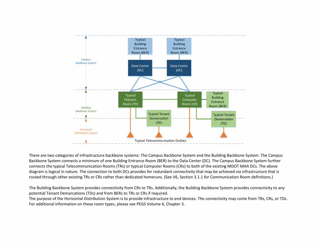
4.2 Infrastructure Configuration Concept DAT has established the following philosophy as the ideal, strategic configuration for infrastructure connectivity on MDOT MAA properties. The following conceptual diagram provides a high-level understanding of the implementation strategy to be used on future projects. The existing physical configuration should be confirmed with DAT during the design process.
Horizontal Distribution System
Building Backbone System
Campus Backbone System
Typical Building Entrance
Room (BER)
Data Center (DC)
Typical Computer Room (CR)
Typical Telecom.
Room (TR)
Typical Tenant Demarcation
(TD)
Data Center (DC)
Typical Building Entrance
Room (BER)
Typical Telecommunication Outlets
Typical Tenant Demarcation
(TD)
Typical Building Entrance
Room (BER)
There are two categories of infrastructure backbone systems: The Campus Backbone System and the Building Backbone System. The Campus Backbone System connects a minimum of one Building Entrance Room (BER) to the Data Center (DC). The Campus Backbone System further connects the typical Telecommunication Rooms (TRs) or typical Computer Rooms (CRs) to both of the existing MDOT MAA DCs. The above diagram is logical in nature. The connection to both DCs provides for redundant connectivity that may be achieved via infrastructure that is routed through other existing TRs or CRs rather than dedicated homeruns. (See V6, Section 3.1.1 for Communication Room definitions.) The Building Backbone System provides connectivity from CRs to TRs. Additionally, the Building Backbone System provides connectivity to any potential Tenant Demarcations (TDs) and from BERs to TRs or CRs if required. The purpose of the Horizontal Distribution System is to provide infrastructure to end devices. The connectivity may come from TRs, CRs, or TDs. For additional information on these room types, please see PEGS Volume 6, Chapter 3.
4.3 Pathways Telecommunication pathways provide both routing and protection for telecommunication pathways. Optimal design and installation of these pathways require an understanding of general guidelines as well as specifics associated with underground and indoor conduits, innerducts, cable trays and risers. The following paragraphs in conjunction with the DAT specifications and industry standards provide that guidance for pathways to be installed at MDOT MAA facilities. All DAT pathways shall adhere to the following specification sections:
A. 270526 Grounding and Bonding for Communication Systems B. 270528 Pathways for Communication Systems C. 270536 Cable Trays for Communication Systems
4.3.1 General Guidelines 4.3.1.1 Backbone Containment Pathways Backbone containment pathways (used for Campus and Building Backbone) shall provide cable pathways between locations for the purpose of backbone distribution. Primary and secondary cables to any single destination shall not share containment, not be located within the same corridor or space together and shall follow physically separate pathways to the greatest extent possible. Entry into a communication room shall be in two diverse locations with a minimum separation of 6’-0” as room layout allows. The cable shall be routed to maintain the separation as cable trays and conduits allow until routed into an equipment cabinet or rack for the purpose of final termination. Within a cabinet or rack, primary and secondary cables shall route on opposing sides. Typically, backbone pathways will carry larger diameter cables and particular care to minimum bend radii and containment transitions must be observed during final detailed design. All containment must provide adequate support for routed cables and must have facility for bundles of cables to be secured at regular intervals. Backbone containment pathways are recommended to be routed in conduit. If backbone is routed in cable tray, innerduct or armored cabling is required.
4.3.1.2 Distribution Containment Pathways Distribution containment pathways are required to provide continuing containment routes from primary containment pathways to final data outlet locations. Distribution containment pathways are typically tertiary containment consisting of cable tray, conduit drops, and flexible conduit links.
4.3.1.3 Separation of Services The infrastructure containment system shall be designed such that power and data cable separation fully complies with minimum requirements of applicable codes, industry standards referenced in this document, and manufacturer installation guidelines. Data cabling shall be separated from power cables and RF inductive loop/leaky feeder types of cable to avoid the possible effects of RFI and EMI. As a minimum, the distances which shall be maintained for separation of services are shown in Table 4.3-1, Separation Requirements.
Separation Requirements Between Power and Data Cabling

Cable Rating – Load Volts/ Amps Minimum Separation Distances
240V – 15A 12” (0.35m)
415V – 50A 24” (0.58m)
415V – 500A 36” (1.0m)
11,000V – 500A 60” (1.4m)
Table 4.3-1, Separation Requirements
Where the necessary cable separation distances cannot be maintained, all efforts shall be made to identify an alternative route. If there are no options available, then as a last resort the use of metallic conduits shall be adopted. All variances from minimum separation alternatives must be approved in writing by DAT.
4.3.1.4 Redundancy Separation Requirements Physically separate backbone routes shall be maintained in the buildings to ensure cables designed to provide resilient connectivity are not routed on the same containment. Primary and secondary routes between any two locations shall maintain a minimum physical separation of 10 feet at wherever possible outside of communication rooms. When not feasible, the DCI shall seek written DAT approval of alternatives maintaining the maximum separation distance possible. When routing backbone cabling into a communication room or an equipment cabinet for the purpose of final termination, primary and secondary cables shall be terminated in separate racks or cabinets when possible. If not possible, then within a single rack or cabinet, primary and secondary cables shall route on opposing sides.
4.3.1.5 Pathway Fill Ratios A. Communication conduit containment routes shall have a maximum cable fill ratio of 40% (for three cables and over), otherwise 31% for two
cables and 53% for one cable shall apply for instances when innerduct is not used. The conduit fill and the use of long radius conduit fittings or bands this shall assist in maintaining minimum bend radii of cables.
B. Useable cable tray capacity is noted as being when the total cable cross sectional areas reach 50% of the tray fill area. 1. New installations shall comply with fill requirements noted in Specification 27536 Cable Trays for Communication Systems, Part 3,
Section 3.2. 2. DCI to confirm current fill of all existing MDOT MAA cable trays intended for use. The additional cables to be install in existing MDOT
MAA cable trays shall not cause the filled to beyond 40% of the usable capacity per the NEC fill ratio and per manufacturer recommendation/guidelines. Use of existing cable tray beyond 40% of useable capacity shall be approved in writing by MDOT MAA DAT.
4.3.1.6 Bend Radii Minimum bend radii shall be as specified by applicable standards, or as shown in the table below. Additional consideration in defining bend

radius requirements of the pathway is the minimum requirement as noted by the cabling manufacturer of cables to be routed within the pathway. At no time may the minimum radii be less than the allowable radii specified by the cable manufacturers. Provide only long bend conduit sweeps or bends to facilitate the cable bending radius as noted below.
Communication Conduit Minimum Bend Radius Requirements
Media Type / Location of
Bend Minimum Requirement
Copper
Minimum bending radius for pulling
during installation
8 times outer cable diameter
Minimum bending radius installed
4 times outer cable diameter
Fiber
Minimum bending radius for pulling
during installation
20 times outer cable diameter
Minimum bending radius installed
10 times outer cable diameter
Table 4.3-2, Minimum Bend Radii
4.3.1.7 Fire Stopping All locations where DAT containment passes through rated wall openings, fire separation barriers or fire compartments shall be fire stopped with an approved fire rated assembly/system in accordance with the building’s applicable code(s). Only provide fire stop materials approved by the Authority Having Jurisdiction (AHJ) and the cable manufacturer shall be used. The material shall enable addition of further cables to routes in the future with only minor rework required to restore the fire rating of the penetrated barrier. DCI shall confirm all fire stopping meets or exceeds requirements noted in the PEGS firestopping guidelines and specifications. Typical penetration details can be found in Appendix 6C, Section 4 Containment Penetrations. Any deviation from the depicted concepts must be approved in writing by DAT.
4.3.1.8 Grounding and Bonding DAT containment must meet all requirements for grounding and bonding as noted in Specification 270526 Grounding and Bonding for Communication Systems and elsewhere in this document. Grounding or Earthing is a conducting connection, whether intentional or incidental, by which an electric circuit or equipment is connected to earth, or to some conducting body of relatively large extent that serves in place of the earth. Bonding is defined as the permanent joining of metallic parts to form an electrically conductive path that will assure electrical continuity
and the capacity to conduct safely any current likely to be imposed. For Communication Systems, grounding and bonding is intended to provide not only the traditional life safety purposes, but also to provide protection for the DAT equipment to prevent damage due to surges or other differences in potential that could damage or interfere with the operation of the DAT equipment. Typical busbars and schematic details can be found in Appendix 6C, Section 6 Grounding. Any deviation from the depicted concepts must be approved in writing by DAT.
4.3.2 Underground Pathways Underground pathways require special considerations during design due to the additional cost and time required for installation. All underground pathways shall be designed for future growth and minimized disruption for future cabling changes. Additionally, the following factors shall be considered when designing an underground pathway system.
4.3.2.1 General Underground Considerations A. Cable size, length, weight, and quantity of cables installed in each pathway. B. Impact on airport operations during installation and future maintenance.
4.3.2.2 Underground Conduit Considerations A. The overall length of the raceway from source to destination B. The length of raceway between pulling points C. The quantity of bends and offsets between pulling points to ensure no more than 180 degrees of deflection between pull points D. The maximum pulling tension recommended by the cable manufacturer E. The minimum bend radius recommended by the cable manufacturer F. The minimum depth raceway shall be installed under runways, taxiways, apron areas, roadways, walkways, etc. G. Location, size, and quantity of manholes/handholes H. Protection of the raceway system I. Provide concrete encasement for all underground conduits as coordinated with DAT and designed in accordance with project civil
engineer J. Manholes shall be rated to accommodate vehicle traffic with the vehicle types as expected in the installation location. Manholes should
be designed to accommodate vehicle traffic based upon potential roadway, taxiway, or apron expansions or widening that may route traffic differently in the future.
4.3.3 Indoor Conduit and Innerducts 4.3.3.1 System Use
A. All Life Safety and Public Safety infrastructure (Copper and Fiber) shall be installed in conduit unless approved by DAT and the Authority
Having Jurisdiction (AHJ). Termination point(s) will be specified by the DAT. B. All Airport Security System device cabling shall be installed in conduit. See Division 28 Specifications for additional information.
4.3.3.2 Conduit Pathway Type Use A. Indoors:
Apply pathway products as specified below unless otherwise indicated. 1. Exposed, Not Subject to Physical Damage: EMT. 2. Exposed and Subject to Severe Physical Damage: GRC. Pathway locations include the following:
a. Mechanical, electrical, and utility rooms. b. Loading dock. c. Corridors used for traffic of mechanized carts, forklifts, and pallet-handling units. d. Baggage handling areas. e. Exposed conduits that are below 8’-0” AFF.
3. Concealed in Ceilings and Interior Walls and Partitions: EMT. 4. Retrofit in Existing Wall Construction: Flexible conduit, maximum 10’ length 5. Connection to Vibrating Equipment (Including Transformers and Hydraulic, Pneumatic, Electric-Solenoid, or Motor-Driven
Equipment): FMC, except use LFMC in damp or wet locations. 6. Damp or Wet Locations: IMC. 7. Pathways for Optical-Fiber or Communications Cable in Spaces Used for Environmental Air: EMT or Plenum-type optical fiber cable
pathway in innerduct within cable tray. 8. Pathways for Optical-Fiber or Communications-Cable Risers in Vertical Shafts: EMT or Riser-type optical-fiber-cable pathway in cable
tray. 9. Pathways for Concealed General-Purpose Distribution of Optical-Fiber or Communications Cable: EMT or General-use optical-fiber-
cable pathway in cable tray. 10. Boxes and Enclosures: NEMA 250 Type 1, except use NEMA 250 Type 4 stainless steel in commercial kitchens, non-conditioned
spaces, and damp or wet locations.
B. Outdoors Apply pathway products as specified below unless otherwise indicated. 1. Exposed Conduit: PVC coated GRC or painted GRC. 2. Concealed Conduit, Aboveground: GRC, IMC, EMT, RNC, Type EPC-40-PVC. 3. Underground Conduit: RNC, Type EPC-40-PVC. All underground conduits shall be concrete encased unless requirement is waived in
writing by MDOT MAA DAT. Coordinate with MDOT MAA DAT. 4. Connection to Vibrating Equipment (Including Transformers and Hydraulic, Pneumatic, Electric Solenoid, or Motor-Driven
Equipment): LFMC. 5. Boxes and Enclosures Above Ground 6. Housing Active Equipment: NEMA 250 Type 4 (IP66). 7. Housing ONLY Passive Equipment: NEMA 250 Type 3R.
C. Pathway Fittings
Compatible with pathways and suitable for use and location. 1. Rigid and Intermediate Steel Conduit: Use threaded rigid steel conduit fittings unless otherwise indicated. Comply with NEMA FB
2.10. Only long sweep conduits shall be allowed. 2. PVC Externally Coated, Rigid Steel Conduits: Use only fittings listed for use with this type of conduit. Patch and seal all joints, nicks,
and scrapes in PVC coating after installing conduits and fittings. Use sealant recommended by fitting manufacturer and apply in thickness and number of coats recommended by manufacturer.
3. EMT: Use compression, cast-metal fittings. Comply with NEMA FB 2.10. 4. Connection to Vibrating Equipment (Including Transformers and Hydraulic, Pneumatic, Electric-Solenoid, or Motor-Driven
Equipment): FMC, except use LFMC in damp or wet locations.
4.3.3.3 Conduit Size Use A. Conduits install in MDOT MAA facility space shall be a minimum of 1” diameter. B. Conduits install in dedicated tenant space shall be a minimum of 1” diameter if more than one cable is to be installed.
4.3.3.4 Innerduct A. All ISP innerduct must be plenum rated within a plenum ceiling. PVC innerduct will be approved provided the conduit path is continuous
end to end via junction boxes, and that it does not enter the plenum ceiling. B. When providing new conduit exceeding (2) two inch (duct bank or single duct), the contractor shall provide innerduct in the conduit. The
purpose of the innerduct is to allow future use of the duct system. C. Minimum number and size of innerduct to conduit size shall be:
1. 2-inch conduit but less than 4-inch conduit, provide fabric type innerduct 2. 4-inch Conduit, provide (3) 1 1/4-inch wall innerduct 3. For conduits over 4”. coordinate innerduct sizes and quantities with MDOT MAA DAT.
D. All conduits including innerduct shall be provided with a combination conduit measuring / pull tape installed in all empty innerducts. The tape shall include foot graduation markings to allow for the contractor to determine the length of the conduit run in the future. Pull tape selection to be based on the application and maximum tension required for cable to be pulled.
E. No fabric innerduct shall be allowed in conduits under 2-inch, 4-inch and over, or in tray without a variance from MDOT MAA DAT. F. Provide a trace wire in all innerducts that are direct buried and carry fiber, or otherwise would need to be traced or located.

4.3.4 Cable Trays The use of cable trays for cable containment may be used in MDOT MAA facilities. All components must meet the requirements as noted in the associated MDOT MAA DAT Specification 270536. Typical cable tray installation details can be found in Appendix 6C, Section 3 Cable Tracy Installations. Any deviation from the depicted concepts must be approved in writing by DAT.
4.3.4.1 Existing Cable Trays Locations and use of existing cable trays shall be coordinated with DAT via the MDOT MAA Project Manager. Cable trays identified for potential use will be reviewed in conjunction with the proposed cable quantities, type, and purpose to ensure alignment with MDOT MAA requirements. The review shall include documentation of the existing cable tray capacity and loading for the sections proposed to be used.
4.3.4.1 New Cable Trays New cable tray routes may be provided for cable containment. All new cable trays shall be ladder style with two I-beam side rails and transverse rungs. Material and minimum size requirement may be found in the DAT specification. DCI is responsible for coordinating location of cable tray with other trades prior to installation. Selected routing must allow for accessibility to add or remove cables. At no point shall cable tray be routed above hard ceiling, ductwork, conveyors or other items for a distance of greater than 10’. DCI shall transition to conduits having an equal usable capacity as the cable tray to be routed through the conduits for inaccessible distances, accounting for the allowable fill ratios of the conduits.
4.3.5 Risers The infrastructure riser strategy is critical to ensure that telecommunication cable routing can be achieved between floors to support horizontal distribution cable length limitations. Within defined riser spaces, the use of vertical cable tray, conduit, and conduit sleeves may be used to provide riser containment. All components must meet the requirements as noted in the associated MDOT MAA DAT specification.
4.3.5.1 Existing Risers Locations and use of existing infrastructure risers should be coordinated with DAT via the MDOT MAA Project Manager. The coordination shall include the documentation of the existing riser at that location by the contractor, the existing fill, the proposed riser to be utilized, and the cabling proposed to be added as part of that project.
4.3.5.2 New Construction Risers Dedicated primary communication system risers are required to be positioned to allow free access from building areas accessible by DAT staff or contractors without closing or impacting passenger circulation areas. Riser locations are required at building cores to ensure coverage can be
achieved and to ensure adequate resilient routes are available for backbone cabling. Primary communication system risers shall form continuous vertical routes through the building where CRs or TRs are stacked. Riser sizing shall be based on providing a minimum 2 x 24” wide cable trays. Alternatively, the DCI may use conduits sized to provide the same useable capacity as the noted cable tray. Expansion within the route shall be possible through the provision of cable trays to the side walls. Sizing of final tray requirements will be required during detailed scheme design phase. Communication system riser containment will be required to provide a single continuous cabling route for the full height of the riser route. All communication system riser containment shall provide support to cables for the entire route and shall provide the capability and suitable access for cables to be secured at regular intervals for the entire duration of the riser route. Secondary communication system risers will provide connection from each CR or TD Room to the redundant infrastructure serving the area. Secondary risers will be circular sleeved core drilled or precast sleeve penetrations. Final positions will be determined during detailed design phases to ensure that routes are created in usable positions in relation to architectural features and fit out plans. The minimum penetration size for a secondary riser will be a 4” circular core, each core will have a maximum fill ratio of 40%.
4.4 Cabling 4.4.1 Backbone Cabling The Backbone Cable System in a building is the part of the premises distribution system that provides connection between equipment rooms, telecommunication rooms, and telecommunications service entrance facilities. The backbone subsystem provides either indoor (intra-building) connections between floors in multi-story buildings or outdoor (inter-building) connections in campus-like environments.
4.4.1.1 General Backbone Communication Cabling All backbone copper and fiber cabling shall be installed in conduit. Conduit shall be properly sized for quantity and type of cabling. Fiber shall be installed within conduit and the proper rated innerduct. Splicing of fiber optic cables is not allowed without written pre-approval from DAT.
4.4.1.2 Indoor Backbone Cabling Indoor backbone cabling is comprised on high pair count copper cabling and fiber optic cabling. All backbone cabling shall meet the requirements as noted in Specification 271300 Backbone Cabling. Following are the general requirements.
A. Single Mode Fiber Optic Minimum fiber count 24 strands, Terminated with SC connector. B. Multi-Mode Fiber Optic cable requires permission by DAT for use. When approved, minimum fiber count 12 strands, terminated with ST
connector. C. Copper feeder cable: Minimum copper count 100 pair, CAT 3

Note: When redundant and diverse pathways are used, half the pair/strand count shall be in each of the pathways to the communications room as noted above. For example, if 24 strands are to be routed to a specific communication room, 12 strands would be routed through each redundant pathway, providing the full complement of 24 strands.
4.4.1.3 Outdoor Backbone Cabling Outdoor backbone cabling shall be required to be Outside Plant (OSP) rated when working outside the perimeter of conditioned air facilities. All outdoor cabling, copper and fiber optic, shall meet the requirements as noted in Specification 271400 Outside Plant Cabling as well as Specification 271300 Backbone Cabling.
A. High Density Protection Field – Surge Protection for Copper Cable All terminations of Outside Plant (OSP) shall be provided with DAT approved protection fields at both ends of the cable and shall be required on all OSP facilities entering the room when exiting the splice case, the copper cabling shall be routed to a high-density protector frame using stub cables. The protector frame shall be located as close to the entry point as feasible and adjacent to the splice case. Distribution stub cables shall be extended from the protector frame to the main distribution frame.
B. Cable Shield
Copper cable end-to-end continuity isolated from ground; no connection to ground shall be present. No shield or grounding is required on backbone fiber.
C. Splice Enclosures
Splicing of Fiber Optic Cables is not allowed without pre-approval from DAT. Upon approval, DCI shall use splicing enclosures that are re-enterable and filled with re-enterable flooding compound.
D. Installation
All OSP conduits shall be generally buried to a minimum depth of 48” unless approved by DAT Engineer. Final design to be in conjunction with the project civil engineer. NOTE: Any conduits within a roadway easement or within 15’ of an existing roadway shall be buried at a minimum depth of not less than 60”.
E. Unlisted Cables
All unlisted, outdoor cables must be transitioned to equivalent cables rated for use in the install environment within 50’ of the point of entrance into an MAA building. All cable use and transitions must align with NEC Article 770, 800, 820, and 830.
4.4.2 Horizontal Cabling MDOT MAA DAT horizontal cabling is comprised of the following items.
A. Copper UTP Cable B. Fiber Cable C. Low Voltage Cabling D. Coaxial Cabling E. Audio Visual (AV) Cabling F. Faceplates and Modular Jacks
All installed distribution cabling shall meet all requirements as noted in Specification 271500. Additionally, distribution cabling used in non-conditioned spaces will need to meet the requirements of Specification 271400 Outside Plant Cabling. Data outlet sample schedules, mounting heights, and faceplate configuration typical details can be found in Appendix 6C, Section 5 Data Outlets. Any deviation from the depicted concepts must be approved in writing by DAT.
4.4.2.1 MDOT MAA Space Installation Configurations The following requirements are specific to all MDOT MAA spaces within MDOT MAA facilities.
A. Cabling - All cabling shall be routed in conduit or cable tray. The use of J-Hooks is not allowed unless approved in writing by DAT. Copper UTP cabling horizontal distribution cables shall be bundled in groups of no more than 24 cables to avoid potential performance degradation. Do not mix fiber optic, low voltage, coaxial, or AV cabling with the copper UTP cabling; maintain segregation.
B. Work Area Outlets – A modular four port faceplate with four copper UTP cables shall be provided at each designated location. Coordinate with DAT for approval to use of lower quantities of outlets within low demand spaces.
C. Telephone Outlets – A single, flush mount modular faceplate with one UTP cable shall be provided at each designated location. D. Furniture Faceplate – A minimum of a modular, two port faceplate with two UTP copper cables shall be provided at each designated
location.
4.4.2.2 Non-MDOT MAA Space Installation Configurations Upon written approval of DAT, installation configurations for non-MDOT MAA, dedicated use spaces may be allowed to use Airline specific specifications and requirements. Coordinate with DAT for approval. The following information will be required for review.
A. Project Name B. Airline Identification C. Drawing depicting spaces considered to be non-MDOT MAA use locations D. Airline specifications and requirements to be used within the spaces.

4.4.2.3 Preferred Mounting Methods Flush, wall-mounted devices shall be the preferred installation method for communications outlets. All wall-mounted communication outlets shall be recessed in the wall and terminate in a device box and have a device wall plate. Floor-mounted outlets and penetrations shall be avoided. Conduit stub out is not required and preferred NOT to be used to accommodate future move, add, change work.
4.4.2.4Abandoned Facilities All abandoned communications facilities shall be removed, per NEC and NFPA, back to the source unless specifically approved by the DAT and AHJ.
4.4.3 Tenant Provided Fiber Optic Cabling Tenant installed fiber shall be not less than 12 strands and meet all requirements per Specification 271500 Horizontal Cabling. All installed tenant fiber shall be installed as to “Touch” MDOT MAA communications rooms. “Touch” requires the cabling to have coordinated (with DAT) entry into an MDOT MAA TR or CR and land on a tenant provided patch panel located in an approved rack position. Upon departure of the tenant from the physical location the tenant installed fiber becomes the property of MDOT MAA DAT at no charge for use by subsequent tenants or the MDOT MAA.
4.5 DAT Power for End Devices Ease of power availability to support devices is critical to the operation. Therefore, following are general power requirements to be coordinated with the electrical DCI. All electrical installations must adhere to MDOT MAA Guidelines, the National Electrical Code, and specifications associated with the electrical trade. It is the responsibility of the DAT DCI to ensure coordination.
A. Commercial power (dedicated 20A/120V circuit) shall be provided to the Communication Rooms as follows: 1. General use receptables: Provide duplex convenience / housekeeping receptacles on each wall at 16” AFF height for general
maintenance purposes. The convenience / housekeeping receptacles shall be provided on a separate circuit to allow use of maintenance equipment without impacting the dedicated equipment circuits. General receptacles shall be placed on each wall of the communication room, with larger rooms having receptacles every 10’ if wall is longer than 15’. Loading shall be per NEC guidelines. The receptacles shall be accessible at all times and not be blocked by racks, cabinets or other equipment.
2. Equipment Receptacles: Provide receptables at heights as needed for specific wall mounted equipment. Coordinate receptacle type with the wall-mounted equipment provider. Wall mounted equipment shall be provided with dedicated circuits to serve each piece or type of equipment unless otherwise allowed by MDOT MAA DAT.
3. Provide outlet(s) at each equipment rack/cabinet as shown on the plans. Rack/cabinet receptacles shall be dedicated circuits unless otherwise allowed by MDOT MAA DAT. Provide Emergency Power (if available), UPS power (if available), or commercial power as noted on the plans. Provide the outlet type and mounting per the plans and in coordination with any provided UPS units or PDUs.

B. Back-up Power Sources 1. UPS Power - Outlets noted as requiring backup power located where no generator power is available shall be connected a power
source providing five minutes of UPS power based upon the calculated loading of the UPS for the expected equipment to be implemented in the design area.
2. Generator Power - Outlets noted as requiring backup power where generator back-up power is available shall be connected a power source providing 15 minutes of back-up power based upon the calculated loading of the UPS for the expected equipment to be implemented in the design area.
3. UPS units shall be designed so that the calculated loading does not exceed 50% of the inverter capacity upon completion of the project, and the battery backup time shall be not less than the times noted above. The UPS shall be able to have additional batteries added to extend the run time to achieve the run times noted above at up to 80% maximum loading of the inverter.
C. A duplex 20A/120V UPS receptacle shall be installed adjacent to workstation communication faceplates to support MDOT MAA IT PC’s
and associated hardware is required. If centralized UPS power is available and provided, the receptacle shall align with the color requirements noted in PEGS 11.4.3 Receptacles and shall be associated with UPS support. In the event that UPS power is not available, DCI shall coordinate requirement with DAT and electrical DCI.
1. Modular furniture power outlets maybe exempt from the outlet color requirement. Industry approved marking may be used. 2. NOTE: There shall be (1) duplex 20A/120V UPS receptacle next to every installed communications outlet (copper) (if centralized
UPS power is available).
D. All MDOT MAA networked printers shall have a 20/120 VAC outlet protected by individual surge suppression device installed instead of a “standard outlet.”
E. For areas with MDOT MAA IT PC’s that do not have a centralized UPS available or where a centralized UPS is not provided as part of the project, provide emergency power outlets and provide individual UPS units to support each workstation location.

5.1 Local Area Network (LAN) The MDOT MAA DAT Local Area Network (LAN) fault tolerant TCP/IP Ethernet network providing connectivity between each connected end device and servers, storage devices, and internet services. The LAN is converged to support voice, data and video.
5.1.1 Network Equipment MDOT MAA LAN active components are comprised of Cisco devices managed by DAT personnel. The procurement of LAN equipment for projects has been problematic due to the constant evolution of technology. Depending upon the duration of a project, the network equipment models specified during the design may not be available, may be outdated, or may be at end-of-life by the time the project is completed. To prevent the provision of equipment that is not the current MAA DAT standard, the following needs to occur as part of the design: At the approximately 70% design level, the engineer/designer shall coordinate the LAN requirements with DAT. For the coordination, the engineer/designer shall have determined the quantity of network ports to be provided as part of the project, the quantity that are expected to be active at the outset of the project, the breakdown of drops that will connect to the MDOT MAA LAN versus the MDOT MAA Security LAN in each communication room, and the expected maximum bandwidth for each communication room. Based upon the data noted above at that stage of the design, MDOT MAA DAT will meet with the engineer/designer and determine the expected quantity and port count of switches in each communication room as well as determining the expected uplink bandwidth requirements. Based upon the review, DAT will assist the engineer/designer in providing a budget for the LAN equipment that will need to be provided for the project. As the project reaches 95% design, the engineer/designer will need to review the current design and meet with DAT to update the budget based on the current project design. MDOT MAA DAT will provide a final budget to be carried as a line item in the bid. The line item shall include escalation for DCI Overhead and Profit. If the bid of the project is delayed for over three months, the budget line item may need to be escalated to account for inflation or pricing changes, or may need to be reconfirmed with MDOT MAA DAT. The exact model numbers for the LAN equipment will not be provided in the MDOT MAA PEGS specifications. Instead, the DCI will be directed to coordinate the exact model numbers to be provided with DAT a minimum of three (3) months prior to the LAN equipment needing to be installed, with the three months including a minimum of three weeks for DAT to program and configure the switches. The intent is that the LAN switch models will be defined, and the switches procured as late as possible in the project to ensure that up-to-date equipment is provided. Refer to PEGS specification for additional information.
5.1.1.1 Use of Existing Equipment If the design proposes to use spare capacity on existing network switches, the use of the spare capacity must be coordinated with DAT. The use of spare capacity is solely at the discretion of DAT, and if not allowed, the provision of additional network equipment will be required.
5.1.1.2 Additional Equipment Provision of additional active network equipment to be coordinated with DAT. Equipment procured by DCI shall be the current approved model as identified by DAT. Coordination of procurement with DAT may allow use of State contracts for purchase at reduced cost.
5.1.1.3 Addition of Equipment to an Existing Switch Stack or creating a switch stack If existing switches or existing switch stacks are currently in place in the communication room(s) to be used for a project, it may be necessary to expand an existing stack or create a stack with an existing switch. The engineer/designer shall document any existing switches or switch stacks in the existing communication rooms and then coordinate with DAT for the approach to adding switches. If a stack is to be expanded, the engineer/designer shall specify and include any interconnect cables and uplink modules as required to expand or create a switch stack as part of the design.
5.1.2 Configuration and Installation All active network equipment shall be delivered to DAT for configuration and setup. DAT will provide the programming and configuration of the equipment and notify the contractor that the equipment is ready for installation. The DCI shall pick up the equipment from DAT and install the equipment in the designated communication room. Coordination of equipment delivery to meet project deadlines is the responsibility of the DCI.
5.1.3 Network Connectivity ONLY THE OFFICE OF TECHNOLOGY shall make final patching connections or connect circuits to live communications system(s). DCI to coordinate connectivity requirements and schedule with DCI.
5.2 MDOT MAA Wireless Data Network (WDN) The MDOT MAA Wireless Data Network (WDN) is used to provide operational wireless access to the MDOT MAA LAN and internet services. DCI shall coordinate expansion or revision of the system with DAT. Specific system technology (802.11ac/ax) and frequencies (2.4 & 5.0 GHz) as well as performance requirements including signal strength, signal-to-noise ratio, and co-channel interference for the system will be defined based upon the intended use. The requirement for any pre-installation/design modelling will also be determined at that time.
5.3 Other Networks / Public Services There are a number of existing service providers operating at BWI Marshall. Services offered include public Wi-Fi, cable/digital television, telephony, and internet connectivity. All facility expansions or revisions that impact public, airline, or tenant spaces will now require coordination with the entities occupying the space and a single service provider, SmartCity Wireless Solutions of BWI Marshall. The MDOT MAA
has entered into a 15-year agreement with SmartCity Wireless Solutions of BWI Marshall to provide contracted technology services to airlines and tenants at BWI Marshall. SmartCity Wireless Solutions is a team of technology companies providing the systems. Included in the team are:
A. Slice Wireless B. AT&T: Cellular DAS (digital antenna system), C. Juniper Networks-owned Mist: AI-enabled Wi-Fi and Virtual Bluetooth Beacon technology, D. Clear Channel: video, secure sponsors and advertisers, E. NGEN: local network management support, and F. Moon Lighting Electrical Service: installation of the physical infrastructure to support the public services.
Additional information regarding the transition to SmartCity Wireless from existing service providers may be obtained from the MDOT MAA Office of Commercial Management.
5.3.1 Public Wi-fi SmartCity Wireless will design, furnish, install, operate and maintain a high-speed, free public Wi-Fi system throughout BWI Marshall Airport, including the passenger terminal, select areas within parking facilities and the rental car facility.
5.3.2 Distributed Antenna System SmartCity Wireless has installed and operates a distributed antenna system throughout the passenger terminal. The system was implemented to boost cellular connectivity to the MDOT MAA, tenants, and travelling public.
5.3.3 Tenant/Airline Telephone Service SmartCity Wireless will provide airlines and tenants VoIP phone service via a contracted agreement between the provider and the airlines or tenants.
5.3.4 Cable/Digital Television Service SmartCity Wireless will provide cable or digital television programming through ClearChannel or other partners within public spaces of the airport for airline or tenant use upon a contracted agreement between the provider and the airlines or tenants.
5.4 Storage Area Network (SAN)
MDOT MAA DAT operates and manages a system of redundant Storage Area Network (SAN) equipment. Expansion of systems utilizing the SAN must be coordinated with DAT to ensure sufficient capacity to meet storage requirements. DCI shall coordinate number of devices and required storage space with DAT. If it is determined that there is not sufficient capacity to accommodate the request, the project introducing the additional requirements must notify the MDOT MAA Project Manager to coordinate storage expansion to support the need.
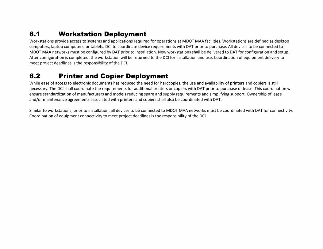
6.1 Workstation Deployment Workstations provide access to systems and applications required for operations at MDOT MAA facilities. Workstations are defined as desktop computers, laptop computers, or tablets. DCI to coordinate device requirements with DAT prior to purchase. All devices to be connected to MDOT MAA networks must be configured by DAT prior to installation. New workstations shall be delivered to DAT for configuration and setup. After configuration is completed, the workstation will be returned to the DCI for installation and use. Coordination of equipment delivery to meet project deadlines is the responsibility of the DCI.
6.2 Printer and Copier Deployment While ease of access to electronic documents has reduced the need for hardcopies, the use and availability of printers and copiers is still necessary. The DCI shall coordinate the requirements for additional printers or copiers with DAT prior to purchase or lease. This coordination will ensure standardization of manufacturers and models reducing spare and supply requirements and simplifying support. Ownership of lease and/or maintenance agreements associated with printers and copiers shall also be coordinated with DAT. Similar to workstations, prior to installation, all devices to be connected to MDOT MAA networks must be coordinated with DAT for connectivity. Coordination of equipment connectivity to meet project deadlines is the responsibility of the DCI.

ATTACHMENT 2
Volume 6, Appendix 6B Standard Specifications
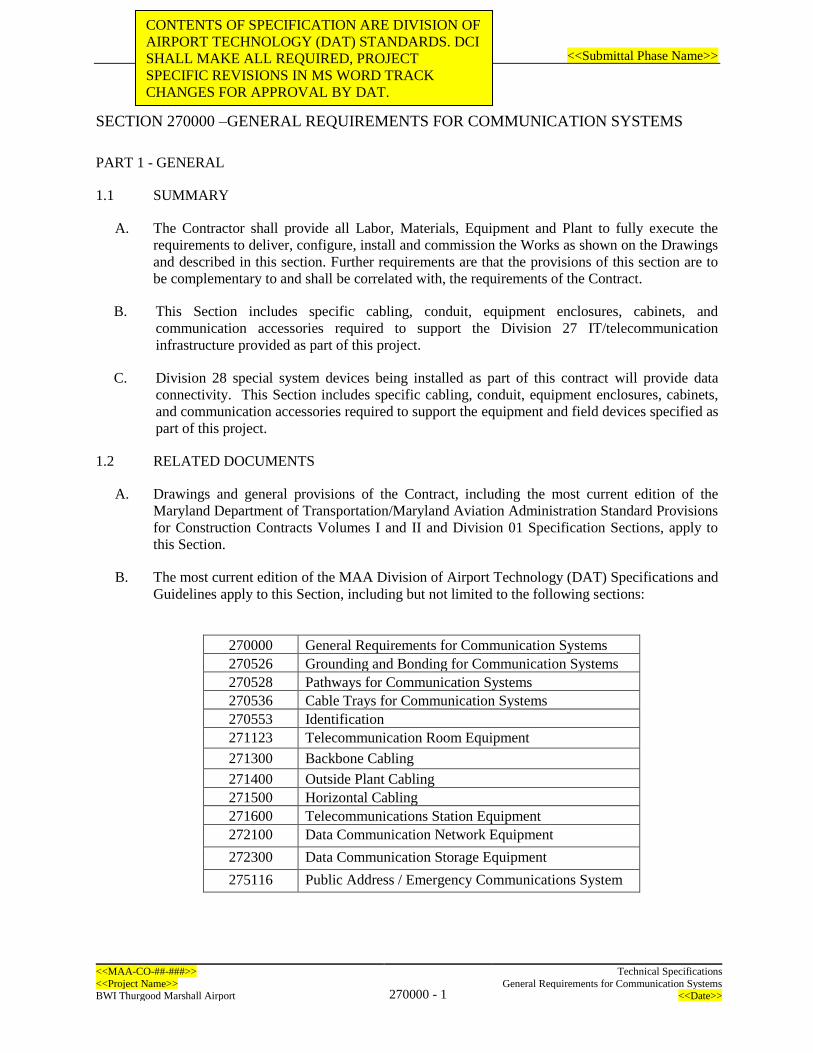
<<Submittal Phase Name>>
<<MAA-CO-##-###>> Technical Specifications
<<Project Name>> 270000 - 1
General Requirements for Communication Systems BWI Thurgood Marshall Airport <<Date>>
SECTION 270000 –GENERAL REQUIREMENTS FOR COMMUNICATION SYSTEMS
PART 1 - GENERAL
1.1 SUMMARY
A. The Contractor shall provide all Labor, Materials, Equipment and Plant to fully execute the
requirements to deliver, configure, install and commission the Works as shown on the Drawings
and described in this section. Further requirements are that the provisions of this section are to
be complementary to and shall be correlated with, the requirements of the Contract.
B. This Section includes specific cabling, conduit, equipment enclosures, cabinets, and
communication accessories required to support the Division 27 IT/telecommunication
infrastructure provided as part of this project.
C. Division 28 special system devices being installed as part of this contract will provide data
connectivity. This Section includes specific cabling, conduit, equipment enclosures, cabinets,
and communication accessories required to support the equipment and field devices specified as
part of this project.
1.2 RELATED DOCUMENTS
A. Drawings and general provisions of the Contract, including the most current edition of the
Maryland Department of Transportation/Maryland Aviation Administration Standard Provisions
for Construction Contracts Volumes I and II and Division 01 Specification Sections, apply to
this Section.
B. The most current edition of the MAA Division of Airport Technology (DAT) Specifications and
Guidelines apply to this Section, including but not limited to the following sections:
270000 General Requirements for Communication Systems
270526 Grounding and Bonding for Communication Systems
270528 Pathways for Communication Systems
270536 Cable Trays for Communication Systems
270553 Identification
271123 Telecommunication Room Equipment
271300 Backbone Cabling
271400 Outside Plant Cabling
271500 Horizontal Cabling
271600 Telecommunications Station Equipment
272100 Data Communication Network Equipment
272300 Data Communication Storage Equipment
275116 Public Address / Emergency Communications System
CONTENTS OF SPECIFICATION ARE DIVISION OF
AIRPORT TECHNOLOGY (DAT) STANDARDS. DCI
SHALL MAKE ALL REQUIRED, PROJECT
SPECIFIC REVISIONS IN MS WORD TRACK
CHANGES FOR APPROVAL BY DAT.

<<Submittal Phase Name>>
<<MAA-CO-##-###>> Technical Specifications
<<Project Name>> 270000 - 2
General Requirements for Communication Systems BWI Thurgood Marshall Airport <<Date>>
1.3 SCOPE OF WORK
A. <DCI TO UPDATE WITH PROJECT SCOPE OF WORK>
B. Refer to the individual specification sections listed in Section 1.2.B for the specific scope of
work related to each specification.
1.4 REFERENCES
A. Publication References (as applicable per system or product):
1. American National Standards Institute (ANSI).
2. ANSI C2 (Latest adopted version); National Electrical Safety Code.
3. Code of Federal Regulations (CFR).
4. CFR 47 Part 15; Radio Frequency Devices.
5. National Fire Protection Association (NFPA).
6. NFPA 70 National Electrical Code (latest adopted version).
7. International Organization for Standardization (ISO) including:
a. ISO 9001; Quality Assurance in Design / Development, Production, Installations,
and Servicing
b. ISO 9003; Quality Assurance in Final Inspection and Test
c. ISO 9004; Quality Management and Quality System Elements Guidelines
8. International Building Code (latest adopted version).
9. UL – Underwriters Laboratory.
10. National Electrical Manufacturers Association (NEMA).
11. Building Industry Consulting Services International (BICSI).
12. Internet Engineering Task Force (IETF).
13. American Society for Testing Materials (ASTM).
14. FM - Factory Mutual.
15. IEEE - Institute of Electrical and Electronic Engineers.
16. OSHA - Occupational Safety and Health Agency.
17. Local, county, state and federal regulations and codes in effect as of date of purchase
shall be complied with.

<<Submittal Phase Name>>
<<MAA-CO-##-###>> Technical Specifications
<<Project Name>> 270000 - 3
General Requirements for Communication Systems BWI Thurgood Marshall Airport <<Date>>
18. Equipment of foreign manufacture must meet U.S. codes and standards. It shall be
indicated in the proposal the components that may be of foreign manufacture, if any, and
the country of origin.
B. Abbreviations
1. <DCI TO UPDATE WITH PROJECT RELATED ABBREVIATION>
C. Definitions
1. <DCI TO UPDATE WITH PROJECT RELATED DEFINITIONS>
1.5 SUBMITTALS
A. The Contractor shall perform no portion of the work requiring submittal and review of record
drawings, shop drawings, product data, or samples until the respective submittal has been
approved by the Owner. Such work shall be in accordance with approved submittals.
B. Qualifications: The Contractor shall submit qualification data sheets for firms and persons as
specified in the “Quality Assurance” article of this specification to demonstrate their capabilities
and experience.
C. Proposed product data sheets: The Contractor shall submit catalog cut-sheets that include
manufacturer, trade name, and complete model number for each product specified. Model
number shall be handwritten and/or highlighted to indicate exact selection. Identify applicable
specification section reference for each product.
D. IDF (Telecommunications Room) Layout: Contractor shall submit shop drawings (floor plan
and elevations) of each equipment cabinet, rack, frames, wall mounted equipment, and
enclosure, and each telecommunications room prior to installing connecting hardware,
termination equipment, racks, cabinets, cable tray or other systems in the rooms.
E. Record Drawings: Furnish CAD drawings of completed work including cable ID numbers
following the Owner’s labeling standards. Submit in hardcopy and electronic formats required
by the MAA’s General and Special Provisions; incorporate into overall Contract Operation and
Maintenance Manuals.
1.6 QUALITY ASSURANCE
A. Contractor Qualifications:
1. The Contractor shall submit references and other related evidence of installation
experience for a period of three years prior to the issue date of this Specification.
2. All work shall be supervised on-site by a BICSI Registered Communications Distribution
Designer (RCDD). Must demonstrate knowledge and compliance with all BICSI,
TIA/EIA, UL, and NEC standards and codes. Contractor shall submit proof of RCDD
designation.
B. Assure that the "as installed" system is correctly and completely documented including
engineering drawings, manuals, and operational procedures in such a manner as to support
maintenance and future expansion of the system.
<<Submittal Phase Name>>
<<MAA-CO-##-###>> Technical Specifications
<<Project Name>> 270000 - 4
General Requirements for Communication Systems BWI Thurgood Marshall Airport <<Date>>
C. Materials and equipment: Equipment shall be rated for continuous operation under the ambient
environmental temperature, humidity, and vibration conditions encountered at the installed
location. The equipment shall meet the following requirements:
1. Interior controlled environment: 60 to 100 degrees F dry bulb and 20 to 90 percent
relative humidity, non-condensing.
2. Interior uncontrolled environment: 0 to 130 degrees F dry bulb and 10 to 95 percent
relative humidity, non-condensing.
3. Exterior environments: Minus 30 degrees to 130 degrees F dry bulb, and 10 to 100
percent relative humidity, condensing.
4. Hazardous environment: All system components located in areas where fire or explosion
hazards may exist because of flammable gas or vapors, flammable liquids, combustible
dust, or ignitable fibers or flyings, shall be rated and installed according to Chapter 5 of
the NEC and as shown.
5. Listing and Labeling: Provide products specified in this Section that are listed and
labeled, as defined in the NEC Article 100.
D. Standard products:
1. Equipment and materials shall be standard products of a manufacturer regularly engaged
in the manufacture of specified products and shall be the manufacturer’s latest standard
design.
2. Items of the same classification shall be identical. This requirement includes equipment,
modules, assemblies, parts, and components.
1.7 INTELLECTUAL PROPERTY
A. Patents: Should patented articles, methods, materials apparatus, etc., be used in this work, the
Contractor shall acquire the right to use same. The Contractor shall hold the Owner harmless for
any delay, action, suit, or cost growing out of the patent rights for all devices or software used
on this Project.
B. Copyrights: Should copyrighted software be used in this work, the Contractor shall acquire the
right to use same. The Contractor shall hold the Owner harmless for any delay, action, suit, or
cost growing out of the copyrights for any software on this Project.
1.8 WARRANTY
A. General Warranty: Refer to MAA’s General and Special Provisions Document for warranty
requirements.
1.9 PROJECT CONDITIONS
A. Site Survey: General routing from existing or new communication rooms will require field
verification to determine the exact routing of the communication cable. The field survey will be
required to include the survey the existing cable tray, conduits, and potential viable above-

<<Submittal Phase Name>>
<<MAA-CO-##-###>> Technical Specifications
<<Project Name>> 270000 - 5
General Requirements for Communication Systems BWI Thurgood Marshall Airport <<Date>>
ceiling pathways in the general vicinity of the project area and beyond the extents of the project
area as required to route to the communication room noted above as required to determine final
routing.
B. Field Measurements: Verify dimensions in areas of installation by field measurements before
fabrication and indicate measurements on Shop Drawings. Coordinate fabrication schedule
with construction progress to avoid delaying the Work.
C. Established Dimensions: Where field measurements cannot be made without delaying the
Work and all reasonable attempts have been made to field verify the dimensions, establish
dimensions and proceed with fabricating units without field measurements. Coordinate
supports, adjacent construction, and fixture locations to ensure actual dimensions correspond to
established dimensions.
1.10 DELIVERY AND STORAGE
A. Equipment shall be delivered in original packages with labels intact and identification clearly
marked.
B. Equipment shall not be damaged in any way and shall comply with manufacturer’s operating
specifications.
C. Equipment and components shall be protected from the weather, humidity, temperature
variations, dirt, dust, or other contaminants. Equipment damaged prior to system acceptance
shall be replaced at no cost to the Owner.
1.11 COORDINATION
A. Coordinate installation of all equipment cabinets, conduit, cabling, and communication systems
work with the Resident Engineer, MAA Division of Aviation Technology (DAT), special
systems subcontractors, and other trades, including mechanical, electrical and plumbing.
B. Coordinate with all contractors providing equipment outside the scope of this contract.
PART 2 - PRODUCTS (NOT USED)
2.1 GENERAL
A. Refer to the related section in each Specification listed under Section Error! Reference source
not found. for product requirements.
PART 3 - EXECUTION
3.1 EXAMINATION
A. The Contractor shall ensure that all work performed under these Specifications is in accordance
with the requirements and standards defined and referenced in these Specifications. Any work
performed in deviation of these Specifications, any of the referenced material, or any applicable
standards or requirements, shall immediately be corrected by the Contractor without additional
charges, regardless of the stage of completion. The Contractor shall record all inspection

<<Submittal Phase Name>>
<<MAA-CO-##-###>> Technical Specifications
<<Project Name>> 270000 - 6
General Requirements for Communication Systems BWI Thurgood Marshall Airport <<Date>>
observations. As a minimum, the record shall include the name(s) of personnel conducting the
inspection, a brief description of the inspection and the observations. These records shall be
available for the Owner to review at any time. Also, these records shall be delivered to the
Owner before final acceptance.
B. Installation Inspections: Installation inspections shall be undertaken through the performance of
pre-installation, in-progress, and final inspections as follows:
1. Pre-Installation Inspection: The Contractor shall make an inspection of all equipment and
material to be used prior to installation. All items shall be verified for compliance with
the requirements of these Specifications and all other applicable standards. All
equipment, cable, and associated hardware identified for installation shall be inspected
for damage and completeness utilizing standard practices to determine integrity and
acceptability.
2. In-Progress Inspection: At the Owner’s discretion, the Contractor shall perform in-
progress inspections that shall include visual inspections of equipment, wiring practices,
cabling, placement of equipment, marking of cables and adherence to safety procedures.
In addition, the Owner, or his representative, may conduct additional inspections any
time.
3. Final Inspection: The Contractor shall conduct a final inspection that encompasses all
portions of the installation. This inspection shall be performed to ensure that all aspects
of the installation have been performed in accordance with these Specifications, standard
industry practices and the publications referenced herein. All non-compliance items shall
be noted by the Contractor during this inspection. The Owner shall witness this
inspection.
4. Corrective Action and Verification Inspection: The Contractor shall perform all
corrective actions to ensure that all non-compliance items identified during the final
inspection have been corrected.
C. Contractor shall verify backboards are properly installed.
D. Contractor shall verify telecommunications grounding system is properly installed and tested
per Specification 270526.
E. Contractor shall verify conduits, cable trays and pull boxes are properly installed per
Specification 270528 and 270536.
F. Contractor shall verify conduit system is properly sized for cables (minimum 1 inch, unless
otherwise noted in Drawings).
G. Contractor shall verify general conduit route following Proposal Drawings and Contractor’s site
survey of existing conditions.
H. Contractor shall verify substrates to which work is connected and determine detail requirements
for proper support.
I. Contractor shall verify proper location and type of rough-in for conduit terminations.
3.2 INSTALLATION
A. Install work following drawings, manufacturer’s instructions and approved submittal data.
<<Submittal Phase Name>>
<<MAA-CO-##-###>> Technical Specifications
<<Project Name>> 270000 - 7
General Requirements for Communication Systems BWI Thurgood Marshall Airport <<Date>>
B. Equipment Clearances
1. Clearance distances are measured from the outermost surface of devices installed in rack
or mounted on wall, rather than from the rack or backboard.
2. Provide a minimum of three feet of space in front and rear of cabinets and racks.
3. Provide a minimum of one-foot side clearance in corners.
4. Provide a minimum of one-foot clearance above top-most item (cable tray, ladder rack or
fiber trough) to any ceiling or overhead condition.
C. Rack and Cabinet Installation
1. Shall be properly positioned, leveled, ganged, anchored, grounded and powered.
2. Shall be populated as noted in drawings with termination hardware, equipment, proper
patch cord lengths, and power outlets.
3. Install and anchor all racks to floor following the drawings and manufacturer’s
instructions. If the rack or cabinet is to be installed on a finished floor surface, the
flooring shall be completed prior to the installation of the rack or cabinet.
D. Conduit Installation:
1. All work shall be supervised and reviewed by contractor’s on-site RCDD.
2. Locations and Types:
a. Provide PVC conduits in buried duct banks or encased in concrete. Provide PVC
coated rigid steel elbows for stub-outs.
b. Install exposed conduit parallel or perpendicular to lines of existing construction
and grouped together where possible, without interfering with use of premises or
working areas. Prevent safety hazards and interference with operating and
maintenance procedures.
c. Conduits that pass-through areas with temperature differential of 20 degrees F or
more shall be sealed with proper fitting at barrier between areas of differing
temperature.
d. Do not install conduit in interference with equipment placement or operation;
piping; structural members; maintenance access; indicated future equipment.
e. Contractor’s RCDD supervisor shall coordinate with drawings of other disciplines
to determine availability of space for installation.
3. Conduit fill shall comply with ANSI/TIA/EIA-569-B.
4. The minimum bend radius is six times the conduit inside diameter (ID) for a two-inch
conduit or less unless media to be installed in conduit is more stringent.
<<Submittal Phase Name>>
<<MAA-CO-##-###>> Technical Specifications
<<Project Name>> 270000 - 8
General Requirements for Communication Systems BWI Thurgood Marshall Airport <<Date>>
5. The minimum bend radius is 10 times the conduit ID for a conduit greater than two
inches.
6. Ceiling conduit or sleeves shall extend six inches below finished ceiling with a bushing.
7. All stubbed conduit ends shall be provided with a ground bushing.
8. All conduit penetrations shall comply with all applicable fire codes. All conduit
penetrations in fire-rated walls or floors shall be sealed and fireproofed to at least the
rating of the penetration area with an approved fire system assembly.
9. Conduits shall be routed in the most direct route, with the fewest number of bends
possible.
10. There shall be no continuous conduit sections longer than 100 feet. For runs that total
more than 100 feet, insert junction or pull boxes (or gutters if appropriate) so that no
continuous run between pull boxes is greater than 100 feet.
11. There shall be no more than two 90-degree bends (180 degrees total) between conduit
pull boxes.
12. Changes in direction shall be accomplished with sweeping bends observing minimum
bend radius requirements above. Do not use pull boxes for direction changes unless
specifically designated otherwise in the Drawings.
13. Unless otherwise noted in the Drawings, conduits entering pull boxes shall be aligned
with exiting conduits.
14. Provide sleeves, sleeve seals, and grouting for wall and floor penetrations per the PEGS
specification requirements.
E. Cabling Installation:
1. All installation shall be done in conformance with ANSI/TIA/EIA-568-B standards,
BICSI methods, industry standards and manufacturers’ installation guidelines. The
Contractor shall ensure that the maximum pulling tensions of the specified distribution
cables are not exceeded and cable bends maintain the proper radius during the placement
of the facilities. Failure to follow the appropriate guidelines shall require the Contractor
to provide in a timely fashion the additional material and labor necessary to properly
rectify the situation. This shall also apply to any and all damages sustained to the cables
by the Contractor during the implementation.
2. The Contractor shall provide a 10-foot service loop at the communications room and
shall provide a three-foot service loop above the access ceiling or cable trays unless
specified otherwise. This allows for future changes or expansion without installing new
cables.
3. All cabling shall be installed in conduit or cable tray.
4. Route all horizontal and similar cables in rear of rack or internal to cabinet clear of spaces
reserved for electronics.
<<Submittal Phase Name>>
<<MAA-CO-##-###>> Technical Specifications
<<Project Name>> 270000 - 9
General Requirements for Communication Systems BWI Thurgood Marshall Airport <<Date>>
5. All cable inventory data documentation shall be submitted in format coordinated with and
approved by MAA DAT so that data can be incorporated into existing databases.
6. Documentation shall include cable identification number, source and destination, type of
cable, length of cable and number of pairs or fibers.
7. Complete cross connect documentation is required. It shall include detailed
documentation of each pair of all horizontal cable.
8. Existing cable noted to be demolished shall be removed after new cabling has been
terminated, tested, and approved for use.
9. Comply with ANSI/TIA-569-E Separation From Power Wiring Table for Balanced
Twisted-Pair Cabling.
10. Twisted-pair cabling shall be separated from the lighting and associated fixtures as well
as active electronic equipment, equipment that have high magnetic fields such speakers,
and devices that emit radio waves such as radio antennas by a minimum of 5 inches
(125mm), both open cabling and cabling in conduit, to provide protection from EMI,
heat, and to provide working clearance to allow for routine maintenance. Provide higher
clearances if recommended by the specific equipment manufacturer.
F. Cable Splices: All cable runs should be continuous; splices shall be done only upon receipt of
written approval from the MAA DAT. The MAA DAT reserves the right to reject any splicing
request. If any unapproved splices are found before acceptance, the Contractor shall replace the
entire spliced cable without any additional charges, regardless of the stage of completion. All
splice locations shall be noted on submitted as-built or record drawings.
G. Grounding: Ground communications room components per MAA PEGS specification 270526
- Grounding and Bonding for Communication Systems requirements.
H. Identification: Per MAA PEGS specification requirements.
I. LAN Switches: LAN switches shall be furnished by the Contractor and then turned over to
MAA DAT for the switches to be configured by MAA DAT staff or their designated
Contractor. Once configured, the switches will be given back to the contract of for installation.
The Contractor shall coordinate the installation of all network equipment with MAA. The
Contractor’s schedule shall allow for a minimum of ten (10) working days for MAA to
configure the LAN switches plus time needed by the contractor to install the switches in the
IDFs.
3.3 CLEANING
A. Upon completion of system installation, including outlet fittings and devices, inspect exposed finish. Remove burrs, dirt, and construction debris and repair damaged finish, including chips, scratches, and abrasions.
B. Communications Rooms may be active during the project. Contractor shall keep Communications Rooms free of debris and dust; and shall not place equipment that prevents others from working in the rooms.

<<Submittal Phase Name>>
<<MAA-CO-##-###>> Technical Specifications
<<Project Name>> 270000 - 10
General Requirements for Communication Systems BWI Thurgood Marshall Airport <<Date>>
C. Remove all unnecessary tools and equipment, unused materials, packing materials, and debris
from each area where Work has been completed unless designated for storage.
3.4 GENERAL TESTING REQUIREMENTS
A. Phases of Testing:
1. Factory Acceptance Testing
2. Integration Testing
3. Endurance Testing
B. Project Testing: The system installation shall not be considered complete until On-Site
Endurance Testing are completed. The purpose is to test the complete system and demonstrate
that all specified features and performance criteria are met. All requirements of the specification
shall be tested, including:
1. Functionality, including reporting and response
2. System capacity
3. Hardware and software interaction
4. Failure Recovery
5. Report generation
C. Test Plan/Procedure: Contractor shall provide six (6) copies of the proposed test
plan/procedures for each testing phase for the review of the Engineer. The test plan for each
phase of testing shall detail the objectives of all tests. The tests shall clearly demonstrate that the
system and its components fully comply with the requirements specified herein. The submission
of Test Plans shall adhere to the following:
1. A draft test plan shall be presented to the Engineer at least forty-five (45) days prior to
the scheduled start of each test
2. A workshop for reviewing comments shall be conducted with the Engineer at least thirty
(30) days prior to the scheduled start of each test
3. A final test plan shall be submitted to the Engineer at least fourteen (14) days prior to the
scheduled start of each test
D. Test plans shall contain at a minimum:
1. Functional procedures including use of any test or sample data
2. Test equipment is to be identified by manufacturer and model including LAN analyzers
and packet sniffers
3. Interconnection of test equipment and steps of operation shall be defined
4. Expected results required to comply with specifications
5. Traceability matrix referencing Specification requirements with specific test procedures
6. Record of test results with witness initials or signature and date performed
7. Pass or fail evaluation with comments
E. The test procedures shall provide conformity to all Specification requirements. Satisfactory
completion of the test procedure is necessary as a condition of system acceptance.
F. All Test plans must be reviewed by the Engineer. To successfully complete a test, the test
document must be signed and dated by both the Contractor and the Engineer.
G. The Engineer will review, witness and validate the execution of all formal test procedures
prepared by the Contractor and deliverable under the contract to assure the tests cover all
<<Submittal Phase Name>>
<<MAA-CO-##-###>> Technical Specifications
<<Project Name>> 270000 - 11
General Requirements for Communication Systems BWI Thurgood Marshall Airport <<Date>>
requirements and that there is a conformity between the conducted test, the test results and
Specification requirements.
H. Documentation verification both interconnects and operationally, shall be part of the test. Where
documentation is not in accordance with the installed system interconnect and operating
procedures, the system shall not be considered accepted until the system and documentation
correlate.
I. The Contractor shall provide the Owner or Owner representative the opportunity(s) to
participate in any or all of tests.
J. Test Reports: The Contractor shall prepare, for each test, a test report document that shall
certify successful completion of that test. [Six (6)] copies of the test report shall be submitted to
the Owner representative for review and acceptance within seven (7) days following each test.
The test report shall contain, at a minimum:
1. Commentary on test results
2. A listing and discussion of all discrepancies between expected and actual results and of
all failures encountered during the test and their resolution
3. Complete copy of test procedures and test data sheets with annotations showing dates,
times, initials, and any other annotations entered during execution of the test
4. Signatures of persons who performed and witnessed the test
K. Test Resolution: Any discrepancies or problems discovered during these tests shall be corrected
by the Contractor at no cost to Owner. The problems identified in each phase shall be corrected
and the percentage of the entire system re-tested determined by the Engineer before any
subsequent testing phase is performed.
3.5 FACTORY ACCEPTANCE TESTING
A. NOT USED <If applicable delete remaining content of 3.5>
B. The purpose of this test is to validate that the individual systems components function as standalone equipment and all specified features are met.
C. The Contractor shall ensure that development of the system is complete, required approvals of submittals have been obtained, and sufficient equipment has been procured to completely demonstrate and test the system.
D. Factory Acceptance testing shall be completed at an Owner authorized test site.
E. Test Setup Equipment: Equipment shall be the actual products or identical models of products to those designated to be delivered and installed at the site. The following equipment shall be setup and used for conducting pre-delivery test: 1. Equipment associated with the system 2. Devices associated with system 3. Software associated with system 4. Administrative tools and equipment 5. Sufficient data to provide accurate simulation of all potential permutations of operational
conditions as required by design
<<Submittal Phase Name>>
<<MAA-CO-##-###>> Technical Specifications
<<Project Name>> 270000 - 12
General Requirements for Communication Systems BWI Thurgood Marshall Airport <<Date>>
F. Acceptance: Acceptance of system to perform sufficiently and provide specified functions shall be determined by the Engineer. Testing may be witnessed by additional Owner authorized personnel.
G. Acceptance Criteria: Performance of system shall equal or exceed criteria stated in individual Specification sections.
H. If system does not perform satisfactorily, the Contractor shall make corrections and modifications and schedule new test with the Engineer.
I. Reporting:
1. Record all test procedures and results 2. Submit report in accordance with reporting requirements in General Testing
Requirements Section.
3.6 INTEGRATION TESTING
A. NOT USED <If applicable delete remaining content of 3.6>
B. The purpose of this test is to validate integration between the system and other interfaced subsystems or systems and to demonstrate that all specified features are met. All requirements of the System integration shall be tested including connectivity, interaction, interface, format, and data flow.
C. Integration testing shall be completed at the systems integration laboratory or other authorized location on-site. Interfaces may be tested using simulated data to/from other systems.
D. Field Testing: All cabling and connectors shall comply with and be tested to ANSI/TIA/EIA-568B.3 and as specified in Part 3.
E. Test Setup Equipment: Equipment shall be actual products or identical models of products to those designated to be delivered and installed at the site. The following equipment shall be setup and used for conducting the test:
1. Equipment associated with the system 2. Devices associated with system 3. Software associated with system 4. Administrative tools and equipment 5. Sufficient data to provide accurate simulation of all potential permutations of operational
conditions as required by design
F. Acceptance: Acceptance of system to perform sufficiently and provide specified functions shall be determined by the Engineer. Testing may be witnessed by additional Owner’s personnel.
G. Acceptance Criteria: Performance of system shall equal or exceed criteria stated in individual Specification sections.
H. If system does not perform satisfactorily, the Contractor shall make corrections and modifications and schedule new test with the Engineer.
I. Reporting:
1. Record all test procedures and results
<<Submittal Phase Name>>
<<MAA-CO-##-###>> Technical Specifications
<<Project Name>> 270000 - 13
General Requirements for Communication Systems BWI Thurgood Marshall Airport <<Date>>
2. Submit report in accordance with reporting requirements in General Testing Requirements Section
3.7 ENDURANCE TESTING
A. NOT USED <If applicable delete remaining content of 3.7>
B. The purpose of this test is to validate that the fully integrated system meets the Endurance and High Availability requirements.
C. Integration testing shall be completed on-site at the [Site name]. All interfaces shall be tested using actual interfaces to other systems (i.e. no stubs or dummy data.)
D. Requirements:
1. Provide personnel to monitor system operations 24 hours per day, including weekends and holidays during Endurance Testing
2. Start test after:
a. Successful completion of Integration Testing b. Training as specified has been completed c. Correction of deficiencies has been completed d. Receipt of written start notification from the Engineer
3. Monitor all systems during Endurance Testing. Coordinate monitoring with the Engineer 4. Recording: Record data on forms so as to provide a continuous log of systems
performance. Include:
a. Date and time for all entries b. Name of individual making entry c. Environmental conditions d. Activities in process e. Description of all alarms, responses, corrective actions, and causes of alarms.
Classify as to type of alarm f. Description of all equipment failures, including software errors g. Description of all maintenance and adjustment operations performed on system h. Daily and weekly tabulations i. Daily entries of performance data shall be reviewed by the Engineer
5. Owner may terminate testing at any time when the system fails to perform as specified. Upon termination of testing the Contractor shall commence an assessment period as described in Stage II
E. Testing
1. Stage I - Initial Phase Testing:
a. Time: 24 hours per day for 30 consecutive calendar days b. Make no repairs during this stage unless authorized in writing by the Engineer c. If system experiences no failures, proceed to Stage III - Final Testing
2. Stage II - Initial Phase Assessment:

<<Submittal Phase Name>>
<<MAA-CO-##-###>> Technical Specifications
<<Project Name>> 270000 - 14
General Requirements for Communication Systems BWI Thurgood Marshall Airport <<Date>>
a. After conclusion of Stage I, or terminating of testing, identify all failures, determine causes, and repair. Submit report explaining: Nature of each failure, corrective action taken, results of tests performed to verify corrective action as being successful, and recommended point for resumption of testing
b. After submission of report, schedule review meeting at job site. Schedule date and time with the Engineer
c. At review meeting, demonstrate that all failures have been corrected by performing verification tests
d. Based on report and review meeting, the Engineer will direct Contractor to repeat Stage I, restart Stage I, or proceed to Stage III - Final Testing
3. Stage III - Final Phase Testing:
a. Time: 24 hours per day for 15 consecutive calendar days b. Make no repairs during this stage unless authorized in writing by the Engineer
4. Stage IV - Final Phase Assessment:
a. After conclusion of Stage III or termination of testing, identify all failures, determine causes, and repair. Submit explaining the nature of each failure, corrective action taken, results of tests performed, and recommended point for resumption of testing
b. After submission of report schedule review meeting at job site. Schedule date and time with the Engineer
c. At review meeting, demonstrate that all failures have been corrected by performing verification tests
d. Based on report and review meeting, the Engineer will review Endurance Test or direct Contractor to repeat all or part of Stages III and IV
F. Adjustment, Correction, and Maintenance
1. Adjustment and Correction: Make adjustments and corrections to system only after obtaining written approval of the Engineer
2. Maintenance: Perform required maintenance on systems including provision of replacement parts
G. Final Inspection and Acceptance
1. After Endurance Testing is complete, review tabulated records with the Engineer 2. Contractor will not be responsible for failures caused by:
a. Outage of main power in excess of backup power capability provided that automatic initiation of all backup sources was accomplished and automatic shutdowns and restarts of systems performed as specified
b. Failure of any owner furnished power, communications, and control circuits provided failure not due to Contractor furnished equipment, installation, or software
c. Failure of existing Owner equipment provided failure not due to Contractor furnished equipment, installation, or software
3. When performance of system does not fall within the above parameters, determine cause of deficiencies, correct, and retest
4. When requested by the Engineer, extend monitoring period for a time as designated by the Engineer
5. Period shall not exceed 60 days exclusive of retesting periods caused by termination of Stages I or III and assessment period of Stages II and IV
6. Submit final report of Endurance Testing containing all recorded data

<<Submittal Phase Name>>
<<MAA-CO-##-###>> Technical Specifications
<<Project Name>> 270000 - 15
General Requirements for Communication Systems BWI Thurgood Marshall Airport <<Date>>
3.8 MAINTENANCE AND SUPPORT
A. General
1. The Contractor shall provide maintenance and support of all components associated with this system at no additional charge during the warranty period. This extends to systems requiring vendor pre-purchased maintenance agreements.
2. The Contractor shall supply a list of special tools, test equipment, and outside inventory required for this Project. The Contractor may recommend specific items to facilitate long-term support of the system as an option
3. All lead technicians performing installation and maintenance shall have a minimum of two (2) years of experience on the proposed system and be manufacturer certified on all hardware/software applications. All maintenance technicians shall be provisioned to attend a one (1) week manufacturer training class each year. Pre-assigned backup technicians shall be available to backfill for onsite technicians who are on vacation, in training or who are out sick
4. The Contractor shall provide twenty-four (24) hours/seven (7) days a week telephone support as a minimum maintenance and support agreement. Additionally, the Contractor shall specify a maximum amount of time to get the system up and operational in the event of a system failure. This time period shall be subject to Owner’s approval
B. Hardware and Software Support
1. Hardware and Software support shall be supplied by the Contractor directly or by a Sub-Contractor reviewed by the Owner. Support shall cover all equipment and systems referenced in this Specification
2. The Contractor shall assume full responsibility for the performance of all equipment supplied by the Owner, provided that such equipment meets the specifications set forth by the Contractor
3. All software shall be delivered with an installable backup
C. Pricing after Warranty Period: Cost of maintenance and support on a yearly basis after the Warranty period has expired, shall be included as an option to be exercised by the Owner or his designated representative unless otherwise specified. Contractor shall clearly state in the bid the annual cost and availability of the following services that the Owner may wish to use or to continue after the initial Warranty period has expired (Costs shall be given for a three (3) years with additional two (2) years to be renewed on an annual basis):
D. Definitions
1. Preventive and Routine Maintenance: Preventive and routine maintenance services shall be provided in accordance with the provisions of the maintenance manual for each component. Preventative maintenance services shall include inspection, test, necessary adjustment, lubrication, parts cleaning, and upgrades. Routine maintenance services shall include scheduled overhauls as recommended by the equipment manufacturer
2. Emergency Failure: A system failure is considered an emergency if any of the key components are inoperative to the extent the system cannot function in a normal manner. Emergency services shall include inspections and necessary tests to determine the causes of equipment or software malfunction or failure. The emergency services shall include furnishing and installing components, parts, or software changes required to replace malfunctioning system elements. The Contractor shall provide telephone support twenty-four (24) hours a day, seven (7) days a week. The Contractor shall provide support on-site within eight (8) hours of request.

<<Submittal Phase Name>>
<<MAA-CO-##-###>> Technical Specifications
<<Project Name>> 270000 - 16
General Requirements for Communication Systems BWI Thurgood Marshall Airport <<Date>>
3. Support: Support shall be supplied by the Contractor directly or by a sub-Contractor reviewed by the Owner. Support shall cover all equipment referenced in this specification.
3.9 TRAINING
A. The User Training shall include on-the-job-training of at least two (2) weeks. The training shall be conducted on site at BWI.
B. The System Administrators Training shall include on-the-job training. Six (6) weeks of on-the-job training shall be provided. This training may be conducted on-site or off-site. If conducted offsite, the contractor shall provide all transportation, lodging, and meal costs for not less than three attendees.
C. The Contractor shall provide the Owner specified trainees with detailed As-built information by the Contractor. The training shall provide the system Administrators with a working knowledge of the system design and layout and shall provide troubleshooting methods and techniques. In addition, the training shall cover testing, maintenance, and repair procedures for all equipment and applications, which are provided under this Specification.
D. Course materials shall be delivered to the Owner. Final delivery of the course materials shall include a master hard copy of all materials and an electronic copy in a format reviewed in advance by the resident engineer. The Contractor shall record each training course and provide it to the MAA on MAA approved media.
E. All training shall be completed a minimum of two weeks prior to the system becoming operational and utilized by the Owner. Training schedule subject to the Owner’s review.
3.10 FIELD QUALITY CONTROL
A. Post-Installation Testing
1. Contractor shall test each Category 6 cable and each fiber strand of every optical fiber
cable prior to acceptance.
2. Contractor shall supply all of the required test equipment used to conduct acceptance
tests.
3. Contractor shall submit acceptance documentation as defined below. No cabling
installation is considered complete until test results have been completed, submitted and
approved.
4. See Sections 271300, 271400, and 271500 of the PEGS specification requirements for
test procedures, criteria, documentation and equipment requirements.
B. No cable shall be put into service until it is fully tested and accepted by the Resident Engineer
and MAA DAT.
3.11 ACCEPTANCE
A. Once all work has been completed, test documentation has been submitted and approved, and
the Owner is satisfied that all work has been completed in accordance with contract documents,
the Owner will notify Contractor in writing of formal acceptance of the system.
<<Submittal Phase Name>>
<<MAA-CO-##-###>> Technical Specifications
<<Project Name>> 270000 - 17
General Requirements for Communication Systems BWI Thurgood Marshall Airport <<Date>>
B. Acceptance shall be subject to completion of all work, successful post-installation testing which
yields 100 percent PASS rating, and submittal and approval of full documentation as described
above.
C. Owner reserves the right to conduct, using Contractor equipment and labor, a random re-test of
up to five percent of the cable plant to confirm documented results. Random re-testing, if
performed, shall be at the expense of the Owner, using standard labor rates. Any failing cabling
shall be re-tested and restored to a passing condition at no cost to the Owner. In the event more
than two percent of the cable plant fails during re-test, the entire cable plant shall be re-tested
and restored to a passing condition at no additional cost to the Owner.
D. Owner may agree to allow certain cabling runs to exceed standardized performance criteria (e.g.
length). In this event, such runs shall be explicitly identified and excluded from requirements to
pass standardized tests.
END OF SECTION 270000
<<Submittal Phase Name>>
<<MAA-CO-XX-XXX>> Technical Specifications <<MAA Project Name>>
270526 - 1
Grounding and Bonding for Communication
Systems
BWI Thurgood Marshall Airport <<Date>>
SECTION 270526 –GROUNDING AND BONDING FOR COMMUNICATION SYSTEMS
PART 1 - GENERAL
1.1 SUMMARY
A. Drawings and general provisions of the Contract, including Terms of Reference and all
contractual conditions apply to this Section.
B. Specification Section 270526 contains the requirements applicable to Grounding and Bonding for
Communication Systems. This document describes the products and execution requirements
relating to providing (furnishing and installing) Grounding/Earthing and Bonding for
Communications Systems.
1.2 RELATED DOCUMENTS
A. Refer to Specification 270000 General Requirements for Communication Systems section 1.2 for
Related Sections.
1.3 SCOPE OF WORK
A. Refer to Specification 270000 General Requirements for Communication Systems section 1.3 for
general Scope of Work.
B. This section includes minimum requirements for the following:
1. Grounding/Earthing System
2. Telecommunications Grounding Bus bar (TGB)
3. Telecommunications Main Grounding Bus bar (TMGB)
4. Telecommunications Bonding Backbone (TBB)
5. Rack/Cable Tray Grounding/Earthing and Bonding
C. All cables and related terminations, support and grounding/earthing hardware shall be furnished,
installed, wired, tested, labeled, and documented by the telecommunications contractor as detailed
in this document.
D. Product specifications, general design considerations, and installation guidelines are provided in
this document. Quantities of grounding/earthing products shall be provided as required for a
complete and operational system as depicted on the project drawings.
E. If the bid documents are in conflict, this specification shall take precedence. The system as
installed shall meet or exceed all requirements for the cable system described in this document.
1.4 REFERENCES
A. Refer to Specification 270000 General Requirements for Communication Systems section 1.4 for
general References.
B. In addition, the following references apply:
CONTENTS OF SPECIFICATION ARE DIVISION OF
AIRPORT TECHNOLOGY (DAT) STANDARDS. DCI
SHALL MAKE ALL REQUIRED, PROJECT
SPECIFIC REVISIONS IN MS WORD TRACK
CHANGES FOR APPROVAL BY DAT.

<<Submittal Phase Name>>
<<MAA-CO-XX-XXX>> Technical Specifications <<MAA Project Name>>
270526 - 2
Grounding and Bonding for Communication
Systems
BWI Thurgood Marshall Airport <<Date>>
1. ASTM B3 - Standard Specification for Soft or Annealed Copper Wire
2. ASTM B8 - Standard Specification for Concentric-Lay-Stranded Copper Conductors,
Hard, Medium-Hard, or Soft
3. ASTM B187/B187M - Standard Specification for Copper, Bus Bar, Rod, and Shapes and
General Purpose Rod, Bar, and Shapes
4. NFPA 780 - Lightning Protection
5. IEEE 1100 - Recommended Practice for Powering and Grounding Electronic Equipment
6. TIA 607-C - Generic Telecommunications Building Grounding (Earthing) for Customer
Premises
7. UL 467 - Grounding and Bonding Equipment
8. UL 910 - Plenum Test
9. ANSI/TIA-942 - Telecommunications Infrastructure Standard for Data Centers
C. Definitions:
1. American Wire Gauge (AWG) – A standardized logarithmic stepped wire gauge system
used for the diameters of round, solid, nonferrous, electrically conducting wire.
2. Bonding – The permanent joining of metallic parts to form an electrically conductive path
that will assure electrical continuity and the capacity to conduct safely any current likely
to be imposed.
3. Common Bonding Network (CBN) – The principal means for affecting bonding and
earthing inside a building.
4. Ground/Earth – A conducting connection, whether intentional or incidental, by which an
electric circuit or equipment is connected to earth, or to some conducting body of relatively
large extent that serves in place of the earth.
5. Impedance – The total opposition of electrical current in ac circuits or an ac waveform
imposed upon a dc or ac circuit or conductor.
6. Retrofit Rack Grounding/Earthing – The application of grounding/earthing products and
technology where equipment is already deployed and functioning.
7. Signal Reference Grid – Provides a low impedance equipotential plane to protect sensitive
electronic equipment from voltage transients.
1.5 SUBMITTALS
A. Refer to Specification 270000 General Requirements for Communication Systems section 1.5 for
general Submittals.
B. In addition, the Contractor shall provide the following:
1. Final grounding and bonding as-built drawings in approved CAD formats.
2. Digital copies and full-size color drawings copies.
3. Physical system topology documentation.
4. Communications room layout documentation.
5. Mark-ups of the Contract drawings showing the actual installed conditions.
1.6 QUALITY ASSURANCE
A. Refer to Specification 270000 General Requirements for Communication Systems section 1.6 for
general Quality Assurance Requirements.
<<Submittal Phase Name>>
<<MAA-CO-XX-XXX>> Technical Specifications <<MAA Project Name>>
270526 - 3
Grounding and Bonding for Communication
Systems
BWI Thurgood Marshall Airport <<Date>>
1.7 WARRANTY
A. General Warranty: Refer to MAA’s General and Special Provisions Document for warranty
requirements.
1.8 INTELLECTUAL PROPERTY
A. Refer to Specification 270000 General Requirements for Communication Systems section 1.8 for
general Project Condition Requirements.
1.9 PROJECT CONDITIONS
A. Refer to Specification 270000 General Requirements for Communication Systems section 1.9 for
general Project Condition Requirements.
1.10 DELIVERY, STORAGE, AND HANDLING
A. Refer to Specification 270000 General Requirements for Communication Systems section 1.10
for general Delivery, Storage, and Handling Requirements.
1.11 COORDINATION
A. Refer to Specification 270000 General Requirements for Communication Systems section 1.11
for general Coordination Requirements.
PART 2 - PRODUCTS
2.1 MANUFACTURERS
A. Available Manufacturers: Subject to compliance with requirements, manufacturers offering
products that may be incorporated into the Work include, but are not limited to, the following:
<<DCI TO REMOVE MANUFACTURERS OF UNUSED PRODUCT TYPES>>
1. Communications Grounding and Bonding Conductors
a. Harger
b. Southwire
c. Texcan
d. Approved Equal
2. Grounding Busbars (TMGB, TGB,RGB)
a. Harger
b. Hubbell
c. Panduit
d. Approved Equal
2.2 PRODUCTS
A. Conductor General Requirements:
1. Grounding wire shall be insulated copper American Wire Gauge (AWG) wire following
ASTM-B3, ASTM-B8 and ASTM-B33.
<<Submittal Phase Name>>
<<MAA-CO-XX-XXX>> Technical Specifications <<MAA Project Name>>
270526 - 4
Grounding and Bonding for Communication
Systems
BWI Thurgood Marshall Airport <<Date>>
2. Ground wire shall be No. 6 AWG or larger physical size. Use of No. 6 AWG ground wire
shall be limited to 100 ft in length. This excludes the sizing for BCT, GE, and TBB which
indicates minimum sizing noted below.
3. Ground wire shall be Green with Yellow stripe insulated copper wire
4. Braided cable shall not be used except for cable tray bonding jumpers as noted below.
5. Plenum-rated grounding and bonding conductors:
a. Installed in plenums or air-handling spaces shall meet UL 910.
b. Shall be marked CMP (communications multipurpose plenum) in accordance with
the NEC.
6. Non-plenum riser-rated grounding and bonding conductors:
a. Shall meet UL 1666.
b. Shall be marked CMR (communications multipurpose riser) in accordance with the
NEC.
<<DCI TO REMOVE UNUSED PRODUCTS FROM BELOW LISTINGS>>
B. Communications Grounding and Bonding Conductors: Insulated copper American Wire Gauge
(AWG) wire following ASTM-B3, ASTM-B8 and ASTM-B33, of following types:
1. Alternating Current Equipment Ground (ACEG):
a. Function: Connects Telecommunications Grounding Busbar (TGB) or
Telecommunications Main Grounding Busbar (TMGB) to a local panelboard when
located in the same room or space as the TGB or TMGB.
b. Conductor: Shall be minimum No. 6 AWG green insulated stranded copper ground
wire.
2. Bonding Conductor for Telecommunications (BCT):
a. Function: Main ground source feed from the building ground system to the
Telecommunications Main Ground Busbar (TMGB)
b. Conductor: Shall be minimum No. 2/0 AWG green insulated stranded copper ground
wire.
3. Grounding Equalizer (GE):
a. Function: Bonds together Telecommunications Bonding Backbones (TBBs) at
TGBs on the first floor, every third floor, and the top floor of multi-level buildings
b. Conductor: Shall be green insulated stranded copper ground wire sized at a
minimum, the same as the largest Telecommunications Bonding Backbone (TBB).
4. Rack Bonding Conductor (RBC):
a. Function: Connects Telecommunications Equipment Bonding Conductor (TEBC) to
Rack Grounding Busbar (RGB).
b. Conductor: Shall be minimum No. 6 AWG green insulated stranded copper ground
wire.
5. Telecommunications Bonding Backbone (TBB):
a. Function: Connects the TMGB to the TGBs
b. Conductor: Shall be green insulated stranded copper ground wire. TBB size shall
comply with J-STD-607 guidelines based upon length of TBB.
c. All jackets shall be UL, VW-1 flame rated, and be copper American Wire Gauge
(AWG) wire following ASTM-B3, ASTM-B8 and ASTM-B33.
d. Sizing of TBB shall be as follows:
TBB Length in Feet (meters) TBB size (AWG)
Less than 13 (4) 6
14-20 (4-6) 4
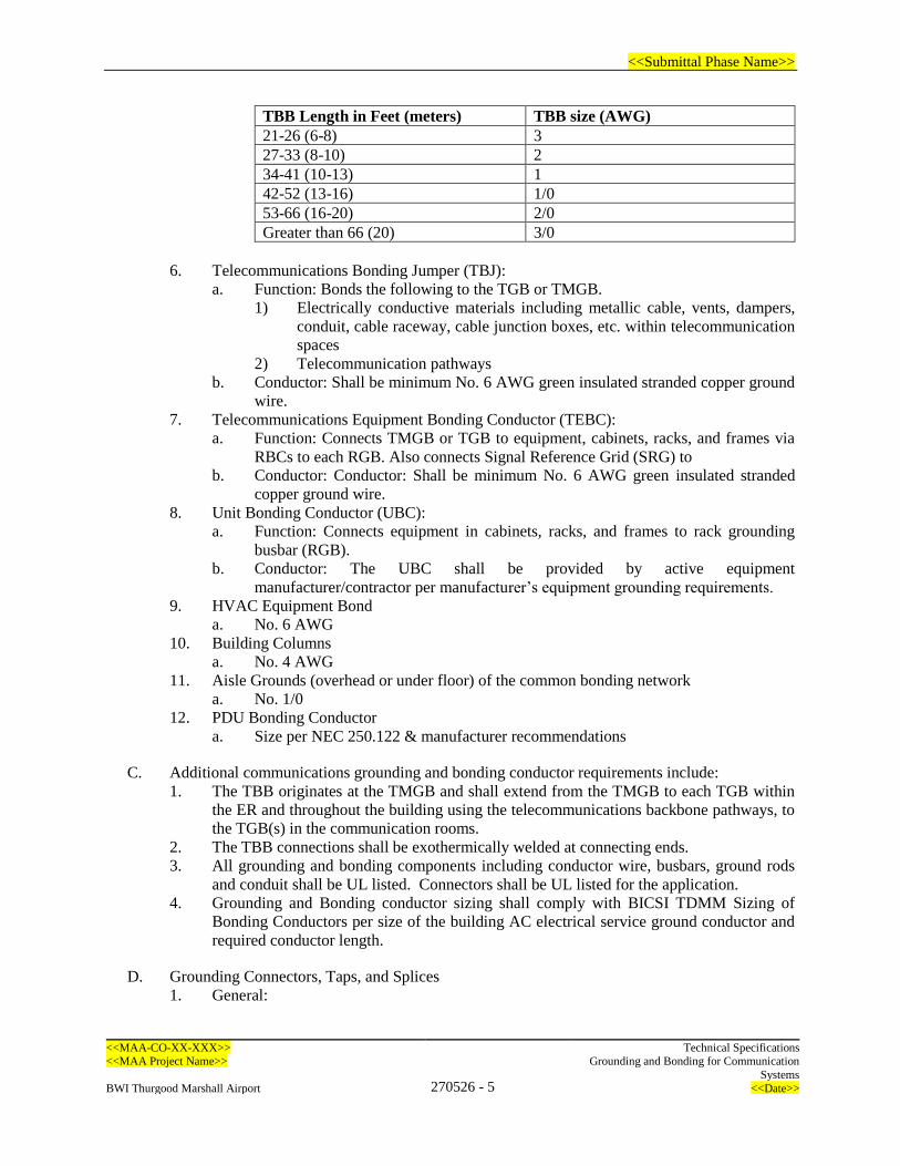
<<Submittal Phase Name>>
<<MAA-CO-XX-XXX>> Technical Specifications <<MAA Project Name>>
270526 - 5
Grounding and Bonding for Communication
Systems
BWI Thurgood Marshall Airport <<Date>>
TBB Length in Feet (meters) TBB size (AWG)
21-26 (6-8) 3
27-33 (8-10) 2
34-41 (10-13) 1
42-52 (13-16) 1/0
53-66 (16-20) 2/0
Greater than 66 (20) 3/0
6. Telecommunications Bonding Jumper (TBJ):
a. Function: Bonds the following to the TGB or TMGB.
1) Electrically conductive materials including metallic cable, vents, dampers,
conduit, cable raceway, cable junction boxes, etc. within telecommunication
spaces
2) Telecommunication pathways
b. Conductor: Shall be minimum No. 6 AWG green insulated stranded copper ground
wire.
7. Telecommunications Equipment Bonding Conductor (TEBC):
a. Function: Connects TMGB or TGB to equipment, cabinets, racks, and frames via
RBCs to each RGB. Also connects Signal Reference Grid (SRG) to
b. Conductor: Conductor: Shall be minimum No. 6 AWG green insulated stranded
copper ground wire.
8. Unit Bonding Conductor (UBC):
a. Function: Connects equipment in cabinets, racks, and frames to rack grounding
busbar (RGB).
b. Conductor: The UBC shall be provided by active equipment
manufacturer/contractor per manufacturer’s equipment grounding requirements.
9. HVAC Equipment Bond
a. No. 6 AWG
10. Building Columns
a. No. 4 AWG
11. Aisle Grounds (overhead or under floor) of the common bonding network
a. No. 1/0
12. PDU Bonding Conductor
a. Size per NEC 250.122 & manufacturer recommendations
C. Additional communications grounding and bonding conductor requirements include:
1. The TBB originates at the TMGB and shall extend from the TMGB to each TGB within
the ER and throughout the building using the telecommunications backbone pathways, to
the TGB(s) in the communication rooms.
2. The TBB connections shall be exothermically welded at connecting ends.
3. All grounding and bonding components including conductor wire, busbars, ground rods
and conduit shall be UL listed. Connectors shall be UL listed for the application.
4. Grounding and Bonding conductor sizing shall comply with BICSI TDMM Sizing of
Bonding Conductors per size of the building AC electrical service ground conductor and
required conductor length.
D. Grounding Connectors, Taps, and Splices
1. General:
<<Submittal Phase Name>>
<<MAA-CO-XX-XXX>> Technical Specifications <<MAA Project Name>>
270526 - 6
Grounding and Bonding for Communication
Systems
BWI Thurgood Marshall Airport <<Date>>
a. All connectors shall be listed by an NRTL for the intended purpose and as complying
with NFPA 70 for specific types, sizes, and combinations of conductors and other
items connected. Connectors shall comply with UL 486A-486B.
b. Conduit grounding bushings or ground clamps shall be provided for ground wire
connection.
2. Irreversible Compression Connectors, Taps, and Splices: Electroplated tinned copper
irreversible Crimp-and-compress connectors that bond to the conductor when the
connector is compressed around the conductor. Comply with UL 467. Provide matching
clear covers. C and H Taps shall have a minimum of two clamping elements. I-Beam
clamps shall have a minimum of one clamping element.
3. Two-hole Lugs: Electroplated tinned copper solderless compression or exothermic-type,
mechanical connector; with a long barrel, inspection window, minimally two clamping
elements for compression connectors, and two holes sized and spaced for a two-bolt
connection to the busbar.
4. Welded Connectors: Exothermic-welding kits of types recommended by kit manufacturer
for materials being joined and installation conditions.
5. Signal Reference Grid Connectors: Combination of compression wire connectors, access
floor grounding clamps, bronze U-bolt grounding clamps, and copper split-bolt connectors,
designed for the purpose.
E. Telecommunications Main Ground Busbar (TMGB): The TMGB, located in the main
communications room, shall comply with the following:
1. Predrilled copper busbar with standard NEMA bolt hole sizing and spacing for the type of
connectors to be used.
2. Sized for the immediate requirements and allow for 50% growth. The minimum
dimensions shall be ¼ inch thick by 4 inches wide by 23 inches long.
3. Electroplated tinned copper plated for reduced contact resistance.
4. Contain pre-drilled holes, which shall support a minimum of two tiers of eight No. 6 AWG
copper two-hole compression lugs.
5. ASTM-B187-C11000 Copper bar suitable for use with two-hole compression-type copper
lugs.
6. Provide insulated standoff bracket that provides a 4 inch clearance for access to the rear of
the busbar.
7. Label “TMGB” in black lettering.
F. Telecommunications Ground Busbars (TGB): Each TGB shall comply with the following:
1. Predrilled copper busbar with standard NEMA bolt hole sizing and spacing for the type of
connectors to be used.
2. Sized for the immediate requirements and allow for 50% growth. The minimum
dimensions shall be ¼ inch thick by 4 inches wide by 16 inches long.
3. Electroplated tinned copper plated for reduced contact resistance.
4. Contain pre-drilled holes, which shall support a minimum of two rows of hole sets, with a
minimum of 16 5/16” hole sets and 6 7/16” hole sets ASTM-B187-C11000 Copper bar
suitable for use with two-hole compression-type copper lugs.
5. Provide insulated standoff bracket that provides a 4 inch clearance for access to the rear of
the busbar.
6. Label “TGB” in black lettering.
G. Equipment Cabinet and Rack Ground Busbar (RGB):

<<Submittal Phase Name>>
<<MAA-CO-XX-XXX>> Technical Specifications <<MAA Project Name>>
270526 - 7
Grounding and Bonding for Communication
Systems
BWI Thurgood Marshall Airport <<Date>>
1. The RGB shall include ground bar, abrasive pad, joint compound, label, and mounting
hardware.
2. The RGB shall be suitable for use with two-hole compression-type copper lugs.
3. Horizontal Mounted Busbar: Designed for mounting in 19- or 23-inch equipment racks.
Minimum cross-section dimension of 1-1/2 inch by 1/4 inch. Include a copper splice bar
for transitioning to an adjoining rack. Busbars shall be pre-drilled or tapped minimally with
fifteen pairs of 5/16 inch holes.
4. Vertical-Mounted Busbar: 72 or 36 inches long, minimum cross-section dimension of 5/8
inch by 1/4 inch. Busbars shall be pre-drilled or tapped minimally with fifteen pairs of 5/16
inch holes.
H. Signal Reference Grid (SRG):
1. SRG shall consist of:
2. A welded grid of minimum 2 inch wide by 0.016 inch thick copper strips.
3. No. 6 AWG conductors.
4. Exothermic weld connections.
I. Maintenance Holes and Handholes:
1. Manhole and Handhole grounding connections shall be minimum No. 6 AWG ground wire.
2. Provide a ground busbar in each manhole and handhole.
a. Minimum dimensions shall be ¾ inch in width by ¼ inch in thickness
b. Provide insulated standoff bracket for busbar mounting.
3. Underground grounding conductors shall be bare tinned-copper No. 2 AWG minimum.
J. Grounding System Accessories:
1. Cable Tray Grounding Jumper:
a. Shall have minimum size of No. 6 AWG and not longer than 12 inches.
b. If jumper is a wire, it shall have a crimped grounding lug with two holes and long
barrel for two crimps.
c. If jumper is a flexible braid, it shall have a one-hole ferrule.
d. Jumper shall attach with grounding screw or connector provided by cable tray
manufacturer.
2. Lugs
a. All lugs shall be irreversible compression at a minimum of (2) crimp points. and
meet NEBS Level 3 as tested. Lugs, HTAPs, grounding strips, and bus bars shall
be UL Listed and made of premium quality tin-plated electrolytic copper that
provides low electrical resistance while inhibiting corrosion. No set-screw ground
lugs will be accepted.
2.3 PERFORMANCE REQUIREMENTS
A. The Grounding and Bonding system shall:
1. Maintain zero volts to all equipment enclosures during normal operation.
2. Provide a zero-voltage reference for end use power supplies.
3. Provide a maximum ac current value on any bonding conductor of less than 1 ampere and
a maximum dc current value on any bonding conductor of less than 500 milliamperes.
B. Bonding connections between the nearest available grounding electrode and the busbar in the EF
or TR shall have a maximum resistance of 0.1 ohms.
<<Submittal Phase Name>>
<<MAA-CO-XX-XXX>> Technical Specifications <<MAA Project Name>>
270526 - 8
Grounding and Bonding for Communication
Systems
BWI Thurgood Marshall Airport <<Date>>
PART 3 - EXECUTION
3.1 EXAMINATION
A. Refer to Specification 270000 General Requirements for Communication Systems section 3.1 for
general Examination Requirements.
3.2 INSTALLATION
A. Refer to Specification 270000 General Requirements for Communication Systems section 3.2 for
general Installation Requirements.
B. General
1. Install work following specification requirements, drawings, manufacturer’s instructions
and approved submittal data.
2. The communications ground system shall be independent from all power grounding.
3. Power grounding and/or bonding shall not be allowed to interfere or provide any back feed
or be a conductor to the separate communications ground system source or to any
communications bonded materials or equipment.
4. Labeling shall be provided in compliance with Section 27 05 53 Identification for
Communication Systems.
C. Conductors
1. The main ground source feed to the TMGB in the main communications room shall be an
independent feed from the main building ground system Grounding Electrode Conductor
(GEC).
2. The main ground source feed shall be a No. 2/0 AWG green insulated stranded copper
ground wire from the building ground system to the TMGB in the Main Communication
Room.
3. The TMGB to be bonded to the nearest electrical service panel (either in the room, or if
not present, outside of the room) by a qualified electrician using No. 6 AWG insulated
copper ground wire not to exceed 10 meters.
4. Bonding conductors shall be installed in one continuous length without splices unless using
exothermic connections or listed irreversible compression-type connectors. Bonding
conductors shall be routed as short and straight as practical. Bends in the conductor shall
be made toward the ground location.
5. Do not connect ground wire in power cable assemblies to the communications ground
system.
6. The TBB between the TMGB and the farthest TGB shall be a continuous copper conductor
that should be sized no less than No. 2/0 AWG to a maximum 750 kcmil. This conductor
shall be sized per TIA-607-B.
7. The GE between the TGBs on the same floor on the first, top, and every third floor in a
multistory building shall be continuous copper conductor that shall be sized no less than
No. 6 AWG. The GE shall be, as a minimum, the same size as the largest TBB.
D. Conductor Connections
1. Bonding connections should be made by using compression copper lugs or, within the
ground electrode system, exothermic welding for parts of a grounding system that are
<<Submittal Phase Name>>
<<MAA-CO-XX-XXX>> Technical Specifications <<MAA Project Name>>
270526 - 9
Grounding and Bonding for Communication
Systems
BWI Thurgood Marshall Airport <<Date>>
subject to corrosion, that must carry high currents reliably or for locations that require
minimum maintenance.
2. The No. 2/0 AWG green insulated stranded copper ground wire connections shall be
exothermically welded at connecting ends.
3. Make connections to dry surfaces only. Remove paint, rust, oxides, scales, grease and dirt
from surfaces before making connection. Sand clean a one square inch area, drill, tap, and
bolt conductor and connector to sanded area. Ensure proper conductivity.
4. The No. 2/0 AWG insulated ground wire weld ends shall have a minimum amount of wire
exposure from the conduit to each weld and a minimum amount of insulation removed at
weld.
5. The No. 6 AWG insulated ground wire connecting ends shall have a minimum amount of
insulation removed at ground lug.
6. Stacking of conductors under a single bolt is not permitted when connecting to busbars.
7. Assemble the wire connector to the conductor, complying with manufacturer's written
instructions and as follows:
a. Use crimping tool and the die specific to the connector.
b. Pretwist the conductor.
c. Apply an antioxidant compound to all bolted and compression connections.
8. Conductor Connector Applications:
a. Pipe and Equipment Grounding Conductor Terminations: Bolted connectors.
b. Underground Connections: Welded connectors except at test wells and as otherwise
indicated.
c. Connections to Ground Rods at Test Wells: Bolted connectors.
d. Connections to Structural Steel: Welded connectors.
9. Provide Telecommunications Equipment Bonding Conductor (TEBC) sized at #6 AWG
and not to exceed 100 feet in length, from the nearest TMGB or TGB to all
telecommunications pathways, enclosures, and lightning protection devices located within
or entering the room area and provided under this contract, including:
a. Equipment cabinets.
b. Racks.
c. Enclosures.
d. Consoles.
e. Conduits.
f. Cable tray and raceways.
g. Building Entrance Terminals (BET).
h. Metallic cable shield, sheath and strength members.
i. Splice cases.
j. Lightning arrestors.
k. Vertical steel columns.
l. Signal Reference Grid (SRG).
10. Structural Steel: Where the structural steel of a steel frame building is readily accessible
within the room or space, bond each TGB and TMGB to the vertical steel of the building
frame.
11. Electrical Power Panelboards: Where an electrical panelboard for telecommunications
equipment is located in the same room or space, bond each TGB to the ground bar of the
panelboard.
12. Shielded Cable: Bond the shield of shielded cable to the TGB in communications rooms
and spaces. Comply with TIA/EIA-568-B.1 and TIA/EIA-568-B.2 when grounding
screened, balanced, twisted-pair cables.

<<Submittal Phase Name>>
<<MAA-CO-XX-XXX>> Technical Specifications <<MAA Project Name>>
270526 - 10
Grounding and Bonding for Communication
Systems
BWI Thurgood Marshall Airport <<Date>>
13. Bond the shield of coaxial cables to the grounding bus bar in communications rooms and
spaces.
14. Bond patch panels for overall screened or foiled twisted pair cables to the grounding bus
bar.
15. Ground bonding is not required for short sections of wall and floor sleeves less than 3 feet
in length.
16. Ground bond connection to electrical ground bus within electrical panels shall performed
by a licensed electrician.
E. Conductor Routing
1. Bonding conductors shall be routed parallel and at right angles to architectural components
using minimum wire lengths, bends and changes in direction. Terminations shall be made
directly to the points being bonded.
2. The bend radius shall not be smaller than eight times the diameter of the conductor, or
exceed the manufacturer’s minimum bend radius. No single bend may exceed 90 degrees.
3. Secure grounding and bonding conductors at intervals of not less than 36 inches.
4. Route ground bond conductors under raised floor where available, following designated
telecom pathways.
5. Avoid placement of ground bond wire in conduit. Where ground wire is placed in a
metallic conduit section in excess of 3 feet in length, the ground wire shall be bonded to
both ends of the conduit.
F. Grounding Busbars
1. The TMGB shall be installed at the bottom of the backboard near the building entrance
conduits in the Entrance Facility.
2. Each TGB shall be installed near where the TBB enters or passes through each TR.
G. Equipment Cabinets and Racks
1. Provide and install a ground busbar to be used as an equipment grounding bus in all
equipment cabinets and racks. The ground bar shall be installed consistently along either
the top or bottom, and back of the equipment cabinet or rack.
2. All cabinets and racks shall be provided with a No. 6 AWG insulated RBC ground wire H-
Tapped to a No. 6 AWG insulated TEBC which provides connection to the TMGB or TGB.
Provide one TEBC per every six (6) cabinets or racks.
3. To bond each cabinet and rack to ground (if no grounding lug is provided or if provided
lug is not adequate), sand clean a one square inch area, drill, tap, and bolt conductor and
connector to sanded area. If an adequate grounding lug is provided with the cabinet or rack,
then contractor shall use the existing lug.
4. Provide one RGB for each cabinet, rack and enclosure containing standard EIA-310-D
mounting rails or brackets.
a. Where raised floors are provided and a horizontal RGB is used, mount RGB at the
lowest RU position at the back, or at the front where the back is not accessible.
b. Where no raised floor is provided and a horizontal RGB is used, mount RGB at the
highest RU position at the back, or at the front where the back is not accessible.
H. Cable Raceway and Support System Grounding
1. Provide and install No. 6 AWG insulated ground wire to one end of each cable tray/runway
system and home run to the TMGB or TGB.
2. Provide continuous grounding path between cable tray/runway sections with grounding
strap.
<<Submittal Phase Name>>
<<MAA-CO-XX-XXX>> Technical Specifications <<MAA Project Name>>
270526 - 11
Grounding and Bonding for Communication
Systems
BWI Thurgood Marshall Airport <<Date>>
3. To bond each cable tray section, sand and clean a one square inch area, drill, tap, and bond
conductor and connector to sanded area. Provide cable tray grounding jumper between
every cable tray section.
4. Provide and install No. 6 AWG insulated ground wire from the end of each existing and
new telecommunications conduit and sleeve to the TMGB using grounding bushings for
ground clamps.
I. Signal Reference Grid (SRG)
1. The SRG shall consist of an electrically interconnected mesh of copper grounding
conductors arranged between every fourth row of floor pedestals in intersecting directions
using one of the following methods:
a. Copper strips sized at 26 gauge thick × 2 inches wide secured to the subfloor with
all crossing inter-connections welded (not punched); or,
b. Copper wire No. 6 AWG routed at subfloor level using welding, brazing,
compression or approved grounding clamp at each crossing point.
2. Provide ground to each building steel column within or adjacent to the raised floor with
minimum No. 6 AWG wire.
3. Provide a minimum of three TEBC conductors with separate connections from the
TMGB/TGB to opposite and diversely located intersecting SRG copper strips.
4. Maximum spacing between any two copper mesh grounding conductors shall not exceed
48 inches.
J. Maintenance Holes and Handholes
1. Provide separate ground wire connections from the maintenance hole busbar to the earth
ground connection and to all exposed metallic components of the maintenance hole,
pathways and cable infrastructure.
2. Provide ground rods as required to achieve maximum 5-ohm electrical earth ground. Do
not place ground rods where electrical grounding electrode systems are provided.
K. Building Entrance Cables
1. Properly ground all metallic cable sheath and all unprotected, non-terminated conductors
using No. 6 AWG insulated ground wire to the TMGB or TGB.
L. Rooftop Antennas and Communications
1. The contractor shall coordinate with the Building Lightning Protection system contractor
to ensure all rooftop antennas, antenna lines, antenna mounting structures, metallic cable
tray, enclosures, exterior building camera mounting supports and exterior surge protectors
are bonded to the Building Lightning Protection System.
3.3 DOCUMENTATION
A. Refer to Specification 270000 General Requirements for Communication Systems section 3.3 for
general Documentation Requirements.
B. The communications grounding system is generally described in these specifications and on the
drawings. The final grounding system design shall be submitted as a shop drawing, and the shop
drawing shall be sealed by a qualified PE, licensed in the state that the work is to be performed.
The communications grounding system shall adhere to the recommendations of the ANSI/TIA-
942 and J-STD-607-A standards and shall be installed in accordance with best industry practice.

<<Submittal Phase Name>>
<<MAA-CO-XX-XXX>> Technical Specifications <<MAA Project Name>>
270526 - 12
Grounding and Bonding for Communication
Systems
BWI Thurgood Marshall Airport <<Date>>
3.4 GENERAL TESTING REQUIREMENTS
A. Refer to Specification 270000 General Requirements for Communication Systems section 3.4 for
general Testing Requirements.
B. PERFORMANCE TESTING
1. Comply with the requirements of Section 27 05 00 “Common Work Results for
Communications”
2. Upon completion of the electrical system, including all grounding, the Contractor shall test
the system for stray currents, ground shorts, etc. Approved instruments, apparatus,
services, and qualified personnel shall be utilized. If stray currents, shorts, etc., are
detected, eliminate or correct and/or coordinate with the Electrical Contractor as required.
The maximum allowable AC current shall be less than one ampere and the maximum
allowable DC current shall be less than 0.5 ampere. The maximum allowable potential
voltage difference shall not exceed 1 volt between electrical power and
telecommunications ground references for screened/shielded cabling applications.
3. Upon completion of the electrical system, including all grounding, the Contractor shall test
the Telecommunications Grounding System using the Three-Point method to confirm an
acceptable low impedance bond has been provided to Earth. The maximum allowable value
is 5 ohms to Ground.
4. Upon completion of the electrical system, including all grounding, the Contractor shall test
the TMGB using the Two-Point method to confirm an acceptable low impedance bond has
been provided to the building ground grid. The maximum allowable value for bonding
resistance is 0.1 ohms.
3.5 FACTORY ACCEPTANCE TESTING
A. Refer to Specification 270000 General Requirements for Communication Systems, Section 3.5
for general Factory Acceptance Testing Requirements.
3.6 INTEGRATION TESTING
A. Refer to Specification 270000 General Requirements for Communication Systems, Section 3.6
for general Integration Testing Requirements.
3.7 ENDURANCE TESTING
A. Refer to Specification 270000 General Requirements for Communication Systems, Section 3.7
for general Endurance Testing Requirements.
3.8 MAINTENANCE AND SUPPORT
A. Refer to Specification 270000 General Requirements for Communication Systems, Section 3.8
for general Maintenance and Support Requirements.
3.9 CLEANING
A. Refer to Specification 270000 General Requirements for Communication Systems, Section 3.9
for general Cleaning Requirements.
<<Submittal Phase Name>>
<<MAA-CO-XX-XXX>> Technical Specifications <<MAA Project Name>>
270526 - 13
Grounding and Bonding for Communication
Systems
BWI Thurgood Marshall Airport <<Date>>
3.10 TRAINING
A. Refer to Specification 270000 General Requirements for Communication Systems, Section 3.10
for general Training Requirements.
3.11 FIELD QUALITY CONTROL
A. Refer to Specification 270000 General Requirements for Communication Systems, Section 3.11
for general Field Quality Control Requirements.
3.12 ACCEPTANCE
A. Refer to Specification 270000 General Requirements for Communication Systems, Section 3.12
for general Acceptance Requirements.
END OF SECTION 270526
<<Submittal Phase Name>>
<<MAA-CO-XX-XXX>> Technical Specifications
<<MAA Project Name>> 270528 - 1
Pathways for Communication Systems
BWI Thurgood Marshall Airport <<Date>>
SECTION 270528 – PATHWAYS FOR COMMUNICATION SYSTEMS
PART 1 - GENERAL
1.1 SUMMARY
A. Drawings and general provisions of the Contract, including Terms of Reference and all
contractual conditions apply to this Section.
B. Specification Section 270528 contains the requirements applicable to Pathways for
Communications Systems. This includes infrastructure hardware such as conduits, fittings,
innerduct, hangars and supports.
C. Refer to Section 270536 “Cable Trays for Communications Systems” for cable tray outside of
telecommunications rooms.
1.2 RELATED DOCUMENTS
A. Refer to Specification 270000 General Requirements for Communication Systems section 1.2 for
Related Sections.
1.3 SCOPE OF WORK
A. Refer to Specification 270000 General Requirements for Communication Systems section 1.3 for
general Scope of Work.
B. In addition, the following applies:
1. This section includes the minimum requirements for the following:
a. Surface pathways
b. Wireways and fittings
c. Boxes, enclosures, and cabinets
d. J-Hooks (Not allowed without an approved variance)
1.4 REFERENCES
A. Refer to Specification 270000 General Requirements for Communication Systems section 1.4 for
general References.
B. In addition, the following references apply:
1. ANSI/TIA 569-E - Telecommunications Pathways and Spaces
2. NFPA 70 - National Electrical Code for Industrial Business Owners
3. ASTM A123 - Standard Specification for Zinc (Hot-Dip Galvanized) Coatings on Iron and
Steel
4. ANSI C80.1 - Electrical Rigid Steel Conduit
5. NEMA RN 1 - Polyvinyl-Chloride (PVC) Externally Coated Galvanized Rigid Steel
Conduit and Intermediate Metal Conduit
6. UL-6 - Electrical Rigid Metal Conduit – Steel
7. ANSI C80.5 – Electrical Rigid Metal Conduit - Aluminum
8. UL-6A - Electrical Rigid Metal Conduit – Aluminum
CONTENTS OF SPECIFICATION ARE DIVISION OF
AIRPORT TECHNOLOGY (DAT) STANDARDS. DCI
SHALL MAKE ALL REQUIRED, PROJECT
SPECIFIC REVISIONS IN MS WORD TRACK
CHANGES FOR APPROVAL BY DAT.

<<Submittal Phase Name>>
<<MAA-CO-XX-XXX>> Technical Specifications
<<MAA Project Name>> 270528 - 2
Pathways for Communication Systems
BWI Thurgood Marshall Airport <<Date>>
9. ANSI C80.6 – Electrical Intermediate Metal Conduit
10. UL-1242 – Electrical Intermediate Metal Conduit – Steel
11. ANSI C80.3 – Electrical Metallic Tubing - Steel
12. UL-797 - Electrical Metallic Tubing – Steel
13. NEC Article 300.22 – Wiring in Ducts Not Used for Air Handling, Fabricated Ducts for
Environmental Air, and Other Spaces for Environmental Air (Plenums)
14. UL-360 - Standard for Liquid-Tight Flexible Metal Conduit
15. NEMA FB 1 – Fittings, Cast Metal Boxes, and Conduit Bodies for Conduit, EMT, and
Cable
16. UL-514B – Conduit, Tubing, and Cable Fittings
17. UL-1203 – Standard for Explosion-Proof and Dust-Ignition-Proof Electrical Equipment
for Use in Hazardous Locations
18. UL-467 – Grounding and Bonding Equipment
19. NEMA TC 2 –Selection and Installation of Underground Nonmetallic Raceways
20. UL-651 – Schedule 40, 80, Type EB, and A Rigid PVC Conduit and Fittings
21. UL-1684A – Safety Reinforced Thermosetting Resin Conduit and Fittings
22. NEMA TC 14 – Reinforced Thermosetting Resin Conduit and Fittings
23. UL-1773 – Standard for Termination Boxes
24. UL-514A – Metallic Outlet Boxes
25. UL-50 – Enclosures for Electrical Equipment, Non-Environmental Considerations
26. UL-2024 - Standard for Cable Routing Assemblies and Communications Raceways
27. UL-870 - Standard for Wireways, Auxiliary Gutters, and Associated Fittings
28. UL-5A - Nonmetallic Surface Raceways and Fittings
29. UL-94 - Standard for Tests for Flammability of Plastic Materials for Parts in Devices and
Appliances
30. MFMA-4 - Metal Framing Standards Publication
31. MSS SP-58 - Pipe Hangers and Supports
32. ASTM A 325 - Standard Specification for Structural Bolts
33. NECA 101 - Standard for Installing Steel Conduits (Rigid, IMC, EMT)
34. NECA 105 - Standard for Installing and Maintaining Cable Tray Systems
35. NECA 1 - Standard for Good Workmanships in Electrical Construction
36. NECA/BICSI 568 - Standard For Installing Commercial Building Telecommunications
Cabling
37. NEMA FB 2.10 - Selection and Installation Guidelines For Fittings for Use With Non-
Flexible Metallic Conduit or Tubing (Rigid Metal Conduit, Intermediate Metal Conduit,
and Electrical Metallic Tubing)
38. MSS SP-69 - Pipe Hangers and Supports
C. Abbreviations
1. AHJ Authority having jurisdiction
2. ARC Aluminum rigid conduit
3. EMT Electrical metallic tubing
4. FMC Flexible metal conduit
5. GRC Galvanized rigid conduit
6. HDPE High density polyethylene
7. IMC Intermediate metallic conduit
8. LFMC Liquid-tight flexible metal conduit
9. LSZH Low smoke zero halogen
10. NRTL Nationally recognized testing laboratory
11. o.c. On center
<<Submittal Phase Name>>
<<MAA-CO-XX-XXX>> Technical Specifications
<<MAA Project Name>> 270528 - 3
Pathways for Communication Systems
BWI Thurgood Marshall Airport <<Date>>
12. RMC Rigid metallic conduit
13. RNC Rigid non-metallic conduit
14. RTRC Reinforced thermosetting resin conduit
1.5 SUBMITTALS
A. Refer to Specification 270000 General Requirements for Communication Systems section 1.5 for
general Submittals.
B. Shop Drawings: For custom enclosures and cabinets and custom underground handholes and
boxes. Include plans, elevations, sections, and attachment details.
C. Samples: For wireways and surface pathways and for each color and texture specified, 12 inches
long.
D. Coordination Drawings: Pathway routing plans, drawn to scale, on which the following items are
shown and coordinated with each other, using input from installers of items involved:
1. Structural members in paths of pathway groups with common supports.
2. HVAC and plumbing items and architectural features in paths of conduit groups with
common supports.
3. Underground ducts, piping, and structures in location of underground enclosures and
handholes.
1.6 QUALITY ASSURANCE
A. Refer to Specification 270000 General Requirements for Communication Systems section 1.6 for
general Quality Assurance Requirements.
1.7 WARRANTY
A. General Warranty: Refer to MAA’s General and Special Provisions Document for warranty
requirements.
1.8 INTELLECTUAL PROPERTY
A. Refer to Specification 270000 General Requirements for Communication Systems section 1.8 for
general Project Condition Requirements.
1.9 PROJECT CONDITIONS
A. Refer to Specification 270000 General Requirements for Communication Systems section 1.9 for
general Project Condition Requirements.
1.10 DELIVERY, STORAGE, AND HANDLING
A. Refer to Specification 270000 General Requirements for Communication Systems section 1.10
for general Delivery, Storage, and Handling Requirements.
B. In addition, the following applies:
1. <<Add requirements specific to this section>>
<<Submittal Phase Name>>
<<MAA-CO-XX-XXX>> Technical Specifications
<<MAA Project Name>> 270528 - 4
Pathways for Communication Systems
BWI Thurgood Marshall Airport <<Date>>
1.11 COORDINATION
A. Refer to Specification 270000 General Requirements for Communication Systems section 1.11
for general Coordination Requirements.
PART 2 - PRODUCTS
2.1 MANUFACTURERS
A. Available Manufacturers: Subject to compliance with requirements, manufacturers offering
products that may be incorporated into the Work include, but are not limited to, the following:
<<DCI TO REMOVE MANUFACTURERS OF PRODUCT TYPES NOT USED IN
PROJECT>
1. Metal Conduits and Fittings
a. Atkore/Allied Tube and Conduit
b. Nucor Tubular Products
c. Thomas & Betts
d. Western Tube
e. Wheatland Tube
f. Approved Equal
2. Nonmetallic Conduits and Fittings
a. IPEX
b. Thomas & Betts
c. Carlon
d. Approved Equal
3. Flexible Metallic and Non-metallic Conduit
a. Atkore/AFC Cable Systems, Inc.
b. Anamet Electrical Inc.
c. Southwire Company
d. Approved Equal
4. Boxes and Enclosures
a. Eaton/B-Line
b. nVent/Hoffmann
c. Thomas & Betts
d. Approved Equal
5. Metallic Wireways and Auxiliary Gutters
a. Emerson/B-Line, Inc.
b. nVent/Hoffman.
c. Mono-Systems, Inc.
d. Square D; a brand of Schneider Electric.
e. Approved Equal
6. Non-Metallic Wireways and Auxiliary Gutters
a. Carlon
b. nVent Hoffman
c. Hammond Manufacturing
d. Approved Equal
7. Metallic Surface Pathways
a. Allied Tube & Conduit
b. Wheatland Tube
c. Western Tube
<<Submittal Phase Name>>
<<MAA-CO-XX-XXX>> Technical Specifications
<<MAA Project Name>> 270528 - 5
Pathways for Communication Systems
BWI Thurgood Marshall Airport <<Date>>
d. Approved Equal
8. Non-Metallic Surface Pathways
a. Carlon
b. Allied Tube & Conduit
c. IPEX
d. Approved Equal
9. Hangars and Supports
a. UniStrut
b. All-Thread
c. Eaton
d. Approved Equal
10. Rigid Innerduct / Optical Fiber Cable Pathways and Fittings
a. Alpha Wire Company
b. Carlon
c. Dura-line
d. Endot industries, LLC
e. Innerduct
f. Approved Equal
11. Fabric Innerduct
a. Maxcell
b. Approved Equal
12. J-Hooks (Not allowed without written approval by MAA DAT)
a. Panduit
b. Eaton
c. nVent
d. Approved Equal
2.2 PRODUCTS <<DCI TO REMOVE UNUSED PRODUCTS FROM BELOW LISTINGS
NOT USED IN PROJECT>>
A. Metal Conduits and Fittings:
1. General Requirements for Metal Conduits and Fittings:
a. Listed and labeled as defined in NFPA 70, by a nationally recognized testing
laboratory, and marked for intended location and application.
b. Comply with ANSI/TIA-569-E.
c. The term “Galvanized Rigid Metal Conduit (Galvanized RMC)” shall also refer to
“Galvanized Rigid Conduit (GRC)”.
2. Requirements for Rigid Metallic Conduit (RMC):
a. Comply with ANSI C80.1 and UL-6.
b. Conduit to be seamless with threads on one end and a coupling on the other end.
c. Provide an enamel lubricating coating on the inside of the conduit.
d. Requirements for Galvanized RMC
1) Hot dipped galvanized rigid steel.
2) Threads to be cut and ends chamfered prior to galvanizing.
3) Galvanizing to provide zinc coating fused to inside and outside walls of
conduit.
e. Requirements for PVC-Coated RMC:
1) Comply with NEMA RN 1.
2) Coating Thickness: 0.040 inch (1 mm), minimum.
<<Submittal Phase Name>>
<<MAA-CO-XX-XXX>> Technical Specifications
<<MAA Project Name>> 270528 - 6
Pathways for Communication Systems
BWI Thurgood Marshall Airport <<Date>>
3. Requirements for Aluminum Rigid Conduit (ARC):
a. Comply with ANSI C80.5 and UL-6A.
b. Conduit to be seamless, 6063 alloy, T-1 temper.
c. Pass bending, ductility, and thickness of zinc coating in ANSI C80.1.
4. Requirements for Intermediate Metallic Conduit (IMC):
a. Comply with ANSI C80.6 and UL-1242.
b. Conduit to be seamless, hot dipped galvanized rigid steel.
c. Threads to be cut and ends chamfered prior to galvanizing.
d. Galvanizing to provide zinc coating fused to outside walls of conduit.
e. Provide an enamel lubricating coating on the inside of the conduit.
5. Requirements for Electrical Metallic Tubing (EMT):
a. Comply with ANSI C80.3, UL-797, and conform to NEC Article 300.22.
6. Requirements for Flexible Metal Conduit (FMC):
a. Comply with UL 1; zinc-coated steel
7. Requirements for Liquid-Tight Flexible Metal Conduit (LFMC):
a. Flexible steel conduit with PVC jacket and complying with UL 360
8. Fittings for Metal Conduit:
a. Comply with NEMA FB 1 and UL-514B.
b. Conduit Fittings for Hazardous (Classified) Locations: Comply with UL-1203 and
NFPA 70.
c. Fittings for EMT:
1) Material: Formed steel.
2) Type: Compression.
d. Use of Line Box (LB) fittings shall not be permitted.
e. Fittings and connectors utilizing set screws shall not be permitted.
f. Conduit bodies shall not be permitted.
g. Fittings and connectors for IMC, RMC, and PVC-Coated Galvanized RMC conduit
shall be threaded type.
h. Couplings for RMC and IMC to be single piece threaded, cadmium plated malleable
iron.
i. Couplings for rigid aluminum conduit to be of aluminum construction, 6063 alloy.
9. Expansion Fittings:
a. PVC-Coated or steel to match conduit type, complying with UL-467
b. Rated for environmental conditions where installed.
c. Shall allow for a minimum of four inches of movement
d. Shall be complete with bonding jumpers and hardware.
10. Hubs:
a. Hubs for box connection to be two-piece with outer internally threaded hub to
receive conduit and inner locking ring with bonding screw.
b. Raintight Sealing Hubs:
1) Two-piece type with outer internally-threaded hub to receive conduit.
2) Inner locking ring with bonding screw.
3) Insulated throat.
4) V shaped ring or O-ring.
11. Coating for Fittings for PVC-Coated Conduit:
a. Minimum thickness of 0.040 inch (1 mm)
b. Overlapping sleeves protecting threaded joints
B. Nonmetallic Conduits and Fittings:
1. General Requirements for Nonmetallic Conduits and Fittings:

<<Submittal Phase Name>>
<<MAA-CO-XX-XXX>> Technical Specifications
<<MAA Project Name>> 270528 - 7
Pathways for Communication Systems
BWI Thurgood Marshall Airport <<Date>>
a. Listed and labeled as defined in NFPA 70, by an NRTL, and marked for intended
location and application.
b. Comply with ANSI/TIA-569-E.
2. RNC: Type EPC-40-PVC, complying with NEMA TC 2 and UL-651 unless otherwise
indicated.
3. Rigid HDPE: Comply with UL-651A.
4. Continuous HDPE: Comply with UL-651B
5. RTRC: Comply with UL-1684A and NEMA TC 14.
6. Fittings: Comply with NEMA TC 3; match to conduit or tubing type and material.
7. Solvents and Adhesives: As recommended by conduit manufacturer.
C. Boxes and Enclosures
1. General Requirements for Boxes and Enclosures:
a. Comply with ANSI/TIA-569-E.
b. Boxes and enclosures installed in wet locations shall be listed and labeled as defined
in NFPA 70, by an NRTL, and marked for use in wet locations.
c. All boxes and enclosures shall be sized to maintain minimum bend radius per cabling
manufacturer’s requirements.
d. The term “pull box” shall also refer to “junction box”.
e. The term “device box” shall also refer to “backbox” and “outlet box” when used for
telecommunications.
f. All pull boxes shall be provided with a hinged cover. Where clearances do not allow
full opening of hinged cover, bolt on covers with captive nuts shall be provided.
2. Steel Pull Boxes:
a. Comply with NEMA OS 1.
b. Provide factory applied painted enamel finish color metallic grey.
c. Minimum Dimensions: Refer to ANSI/TIA 569-E for minimum pull box sizing
d. Material: Minimum 14-gauge steel
3. Galvanized Steel Pull Boxes:
a. Comply with NEMA 250 Type 12 (IP52).
b. Minimum Dimensions: Refer to ANSI/TIA 569-E for minimum pull box sizing
c. Material: Minimum 14-gauge steel
4. Cast-Metal Pull Boxes:
a. Comply with NEMA FB 1 and UL-1773
b. Minimum Dimensions: Refer to ANSI/TIA 569-E for minimum pull box sizing
c. Material: Cast aluminum with gasketed cover.
5. Metal Device Boxes:
a. Comply with NEMA OS 1 and UL-514A.
b. Device box extensions used to accommodate new building finishes shall be of same
material as recessed box.
c. Minimum dimensions: 4 inches square by 2-1/8 inches deep.
d. Material: Minimum 16-gauge welded steel
6. Metal Floor Boxes:
a. Metal floor boxes shall be listed and labeled as defined in NFPA 70, by a qualified
testing agency, and marked for intended location and application.
b. Material: Cast metal.
c. Type: Fully adjustable.
d. Shape: Rectangular.
7. Enclosures:

<<Submittal Phase Name>>
<<MAA-CO-XX-XXX>> Technical Specifications
<<MAA Project Name>> 270528 - 8
Pathways for Communication Systems
BWI Thurgood Marshall Airport <<Date>>
a. Provide hinged cover, except where obstructions require use of screw on cover for
access. Provide retaining strap with screw on cover.
b. Metal barriers to separate wiring of different systems and voltage.
c. Enclosure shall have ground lug hole. Contractor to provide ground lug kit.
d. When installed in interior environment:
1) Comply with UL-50 and NEMA 250, Type 1 (IP10)
2) Material shall be steel
3) Finish shall be manufacturer’s standards enamel inside and out.
e. When installed in exterior environment:
1) Comply with UL-50 and NEMA 250, minimum Type 4 (IP66)
2) Material shall be galvanized steel.
f. Hinged:
1) Provide lockable continuous-hinge cover with flush latch unless otherwise
indicated.
g. Screw-on Cover:
1) Screw holes for cover shall be keyhole slots to allow removal of cover without
removing screws.
D. Rigid Innerduct Pathways and Fittings
1. Description: Comply with UL-2024 and ANSI/TIA-569-E; provide flexible-type pathway
with a circular cross section listed and labeled as defined in NFPA 70, by an NRTL, and
marked for intended location and application.
2. Minimum 1” rigid innerduct, but for 4” conduit, provide three (3) minimum 1-1/4”
innerduct per populated conduit.
3. Rigid innerduct shall be corrugated type, orange in color, HDPE, contain pre-installed
measured pull tape, and shall be rated for the application.
a. Plenum Rated
1) Shall be a flexible textile material rated for use in plenum spaces as per UL-
2024.
2) Shall be low smoke zero halogen (LSZH)
3) Shall meet UL 910 standard for plenum applications, orange color.
b. Riser Rated
1) Shall be a flexible textile material rated for use in non-plenum spaces and
risers.
2) Shall be LSZH.
3) Shall meet UL 1666 standard for riser applications, orange color.
c. Outdoor Applications: Shall be rated for ductbank and/or direct burial applications
as shown on the drawings, orange color.
1) All above-ground applications shall be provided with UV protectant
E. Fabric Innerduct Pathways
1. Description: Comply with UL-2024; fabric innerduct designed to maximize conduit
capacity while preserving space for future cabling installations within a conduit pathway.
2. Resistant to ground chemicals and petroleum products.
3. Halogen-free.
4. Constructed of Polyethylene Terephthalate and Nylon 6.
5. Color coded, pre-installed 1250LB pull tape per cell.
6. Fabric innerduct shall be Plenum or Riser rated based upon the installation location.
7. Each cell within a fabric innerduct pack shall be limited to one cable per cell.
8. 2” Fabric Innerduct for use in 2” conduit pathway
<<Submittal Phase Name>>
<<MAA-CO-XX-XXX>> Technical Specifications
<<MAA Project Name>> 270528 - 9
Pathways for Communication Systems
BWI Thurgood Marshall Airport <<Date>>
a. Max cable diameter per cell: .85”
9. Minimum conduit inside diameter: 2.00”
10. Max cells per conduit: 4
a. Max number of cables: 4
11. 3” Fabric Innerduct for use in 3” conduit pathway
a. Max cable diameter per cell: 1.05”
b. Minimum conduit inside diameter: 3.00”
c. Max cells per conduit: 6
d. Max number of cables: 6
F. Metallic Wireways and Auxiliary Gutters
1. Description: Sheet metal trough of rectangular cross section manufactured to required size
and shape, without holes or knockouts, and with hinged or removable covers.
2. General Requirements for Metal Wireways and Auxiliary Gutters:
a. Comply with UL-870 and NEMA 250, Type 1 (IP10) unless otherwise indicated,
and sized according to NFPA 70.
b. Metal wireways installed outdoors shall be listed and labeled as defined in NFPA
70, by a qualified testing agency, and marked for intended location and application.
c. Comply with ANSI/TIA-569-E.
d. Fittings and Accessories: Include covers, couplings, offsets, elbows, expansion
joints, adapters, hold-down straps, end caps, and other fittings to match and mate
with wireways as required for complete system.
e. Wireway Covers: Screw-cover type unless otherwise indicated.
f. Finish: Manufacturer's standard enamel finish.
G. Nonmetallic Wireways and Auxiliary Gutters
1. Description: Fiberglass polyester, extruded and fabricated to required size and shape,
without holes or knockouts. Cover shall be gasketed with oil-resistant gasket material and
fastened with captive screws treated for corrosion resistance. Connections shall be flanged
and have stainless-steel screws and oil-resistant gaskets.
2. General Requirements for Nonmetallic Wireways and Auxiliary Gutters:
3. Listed and labeled as defined in NFPA 70, by an NRTL, and marked for intended location
and application.
4. Comply with ANSI/TIA-569-E.
5. Fittings and Accessories: Couplings, offsets, elbows, expansion joints, adapters, hold-
down straps, end caps, and other fittings shall match and mate with wireways as required
for complete system.
6. Use solvents and adhesives recommended by conduit manufacturer.
H. Metallic Surface Pathways
1. Description: Galvanized steel with snap-on covers, complying with UL-5.
2. Finish: Manufacturer's standard enamel finish in color selected by Architect.
3. Listed and labeled as defined in NFPA 70, by an NRTL, and marked for intended location
and application.
4. Comply with ANSI/TIA-569-E.
I. Non-Metallic Surface Pathways
1. Description: Two- or three-piece construction, complying with UL-5A, and manufactured
of rigid PVC
2. Finish: Texture and color selected by Architect from manufacturer's standard colors.
3. Product shall comply with UL-94 V-0 requirements for self-extinguishing characteristics.
<<Submittal Phase Name>>
<<MAA-CO-XX-XXX>> Technical Specifications
<<MAA Project Name>> 270528 - 10
Pathways for Communication Systems
BWI Thurgood Marshall Airport <<Date>>
4. Listed and labeled as defined in NFPA 70, by an NRTL, and marked for intended location
and application.
5. Comply with ANSI/TIA-569-E.
J. Hangers and Supports
1. General Requirements for Hangers and Supports:
a. Hangers and supports shall be listed and labeled by NRTL acceptable to the local
code and marked for intended use.
b. Provide only materials and equipment of new stock meeting ANSI, NEC, NEMA
(IP) and NRTL requirements and approved by the Engineer.
2. Steel Slotted Support Systems: Preformed steel channels and angles with minimum 13/32-
inch- diameter holes at a maximum of 8 inches on center (o.c.) in at least one surface.
a. Standard: Comply with MFMA-4 factory-fabricated components for field assembly.
b. Material for Channel, Fittings, and Accessories: Galvanized steel.
c. Channel Width: 1-5/8 inches.
d. Painted Coatings: Manufacturer's standard painted coating applied according to
MFMA-4.
e. Protect finishes on exposed surfaces from damage by applying a strippable,
temporary protective covering before shipping.
f. Channel Dimensions: Selected for applicable load criteria.
3. Aluminum Slotted Support Systems: Extruded aluminum channels and angles with
minimum 13/32-inch- diameter holes at a maximum of 8 inches o.c. in at least one surface.
a. Standard: Comply with MFMA-4 factory-fabricated components for field assembly.
b. Channel Width: 1-5/8 inches.
c. Channel Material: 6063-T6 aluminum alloy.
d. Fittings and Accessories Material: 5052-H32 aluminum alloy.
e. Painted Coatings: Manufacturer's standard painted coating applied according to
MFMA-4.
f. Protect finishes on exposed surfaces from damage by applying a strippable,
temporary protective covering before shipping.
g. Channel Dimensions: Selected for applicable load criteria.
4. Conduit and Cable Support Devices: Steel clamps, hangers, and associated fittings,
designed for types and sizes of raceway or cable to be supported.
5. Support for Conductors in Vertical Conduit: Factory-fabricated assembly consisting of
threaded body and insulating wedging plug or plugs for nonarmored communications
conductors or cables in riser conduits. Plugs shall have number, size, and shape of
conductor gripping pieces as required to suit individual conductors or cables supported.
Body shall be made of malleable iron.
6. Structural Steel for Fabricated Supports and Restraints: ASTM A 36/A 36M steel plates,
shapes, and bars; black and galvanized.
7. Mounting, Anchoring, and Attachment Components: Items for fastening electrical items or
their supports to building surfaces include the following:
a. Powder-Actuated Fasteners: Threaded-steel stud for use in hardened portland
cement concrete, steel, or wood, with tension, shear, and pullout capacities
appropriate for supported loads and building materials where used.
b. Mechanical-Expansion Anchors: Insert-wedge-type zinc-coated steel for use in
hardened portland cement concrete, with tension, shear, and pullout capacities
appropriate for supported loads and building materials where used.
c. Concrete Inserts: Steel or malleable-iron, slotted support system units are similar to
MSS Type 18 units and comply with MFMA-4 or MSS SP-58.

<<Submittal Phase Name>>
<<MAA-CO-XX-XXX>> Technical Specifications
<<MAA Project Name>> 270528 - 11
Pathways for Communication Systems
BWI Thurgood Marshall Airport <<Date>>
d. Clamps for Attachment to Steel Structural Elements: MSS SP-58 units are suitable
for attached structural element.
e. Through Bolts: Structural type, hex head, and high strength. Comply with ASTM A
325.
f. Toggle Bolts: All-steel springhead type.
g. Hanger Rods: Threaded steel.
K. Hooks (Not allowed without written approval by MAA DAT)
1. Listed and labeled as defined in NFPA 70, by an NRTL, and marked for intended location
and application.
2. Comply with ANSI/TIA-569-E.
3. Galvanized steel.
4. J shape.
PART 3 - EXECUTION
3.1 EXAMINATION
A. Refer to Specification 270000 General Requirements for Communication Systems section 3.1 for
general Examination Requirements.
B. In addition, the following applies:
1. Verify conduit system is properly sized for cables (minimum 1-inch in all MAA facility
spaces).
2. Verify general conduit route following Drawings.
3. Verify substrates to which work is connected and determine detail requirements for proper
support.
4. Verify proper location and type of rough-in for conduit terminations.
3.2 INSTALLATION
A. Refer to Specification 270000 General Requirements for Communication Systems section 3.2 for
general Installation Requirements.
B. PATHWAY APPLICATION
1. Minimum Pathway Size: 1-inch trade size (100mm) unless noted otherwise.
2. Length of FMC and LFMC shall be limited to 6 feet (1800mm) unless noted otherwise.
3. Provide transition equipment as required when passing between the various conduit types
and installation classifications (indoor, concealed, outdoors, underground, etc.) as noted
below. Transitions shall occur within 12” of the change of installation classification unless
noted otherwise.
4. Indoors: Apply pathway products as specified below unless noted otherwise:
a. Exposed, Not Subject to Physical Damage: EMT.
b. Exposed, Not Subject to Severe Physical Damage: IMC.
c. Exposed and Subject to Severe Physical Damage: RMC. Pathway locations include
but are not limited to the following:
1) Loading dock.
2) Corridors used for traffic of mechanized carts, forklifts, and pallet-handling
units.
3) Mechanical rooms.
<<Submittal Phase Name>>
<<MAA-CO-XX-XXX>> Technical Specifications
<<MAA Project Name>> 270528 - 12
Pathways for Communication Systems
BWI Thurgood Marshall Airport <<Date>>
4) Baggage Handling Areas
d. Concealed in Ceilings and Interior Walls and Partitions: EMT.
e. • Retrofit in Existing Wall Construction: Flexible conduit, maximum 10’ length
f. Connection to Vibrating Equipment (Including Transformers and Hydraulic,
Pneumatic, Electric-Solenoid, or Motor-Driven Equipment): FMC, except use
LFMC in damp or wet locations.
g. Damp or Wet Locations: IMC.
h. Connection from Junction Box to VSS or WAP Device Box: EMT or FMC.
i. Connection from Junction Box to Modular Furniture: EMT or FMC
j. Pathways for Optical-Fiber or Communications Cable in Spaces Used for
Environmental Air: EMT or Plenum-type optical-fiber-cable pathway in cable tray.
k. Pathways for Optical-Fiber or Communications-Cable Risers in Vertical Shafts:
EMT or Riser-type innerduct/optical-fiber-cable pathway in cable tray.
l. Pathways for Concealed General-Purpose Distribution of Optical-Fiber or
Communications Cable: EMT or General-use innerduct/optical-fiber-cable pathway
in cable tray.
m. Boxes and Enclosures: NEMA 250, Type 1 (IP10).
5. Outdoors: Apply pathway products as specified below unless otherwise indicated:
a. Exposed Conduit: GRC.
b. Concealed Conduit, Aboveground: Galvanized RMC, IMC, EMT, RNC, Type EPC-
40-PVC.
c. Underground Conduit: RNC, Type EPC-40-PVC.
d. Connection to Vibrating Equipment (Including Transformers and Hydraulic,
Pneumatic, Electric Solenoid, or Motor-Driven Equipment): LFMC.
e. Connection from Junction Box to VSS or WAP Device Box: LFMC.
6. Boxes and Enclosures, Exposed, Above ground
a. Housing Active Equipment: NEMA 250 Type 4 (IP66).
b. Housing ONLY Passive Equipment: NEMA 250 Type 3R.
C. General
1. Comply with the following standards for installation requirements except where
requirements on Drawings or in this Section are stricter:
a. NECA 1.
b. NECA/BICSI 568.
c. TIA-569-E.
d. NECA 101
e. NECA 105.
2. Comply with NFPA 70 limitations for types of pathways allowed in specific occupancies
and number of floors.
3. Ground communications pathways according to NFPA 70 unless additional grounding is
specified. Comply with requirements in Section 27 05 26 "Grounding and Bonding for
Communications Systems."
4. Identifiers depicted within the drawings are provided for reference only. All final labeling
shall be per 27 05 53 “Identification for Communications Systems” and 27 05 00 “Common
Work Results for Communications”.
5. Comply with requirements in Section 07 84 13 "Penetration Firestopping" for firestopping
materials and installation for penetrations through fire-rated walls, ceilings, and
assemblies.
6. Comply with requirements in Section 27 05 44 "Sleeves and Sleeve Seals for
Communications Pathways and Cabling" for sleeves and sleeve seals for communications.
<<Submittal Phase Name>>
<<MAA-CO-XX-XXX>> Technical Specifications
<<MAA Project Name>> 270528 - 13
Pathways for Communication Systems
BWI Thurgood Marshall Airport <<Date>>
7. Keep pathways at least 6 inches (150 mm) away from parallel runs of flues and steam or
hot-water pipes. Install horizontal pathway runs above water and steam piping.
8. All pathways in public spaces shall be installed concealed unless noted otherwise or as
allowed in writing by DAT. Any conduits installed exposed in areas that are visible to the
public, the conduit shall be painted to match the surrounding structure or walls/ceiling.
9. Complete pathway installation prior to installation of cabling.
10. Remove all burrs and sharp edges from all pathways prior to cable installation.
11. Install work following drawings, manufacturer’s instructions and approved submittal data.
D. Clearances: Comply with the following minimum clearances:
1. Conduits and pull boxes: 12 inches from any parallel electrical metallic cable tray or
conduit.
2. Conduit and pull boxes: 6 inches from any perpendicular electrical conduit crossing.
3. Conduit and pull boxes: 6 inches from lighting and associated fixtures.
4. Provide minimum clearance of 48 inches from electrical motors and transformers.
5. Comply with ANSI/TIA-569-E Separation From Power Wiring Table for Balanced
Twisted-Pair Cabling.
6. Provide additional clearance or approved heat shielding and/or insulation from heat sources
as required to prevent conduit, pull box or cable temperature from exceeding 113 degrees
Fahrenheit (F).
7. Avoid installation above steam lines, or below water or steam lines.
E. Conduit Routing and Installation:
1. Conduit fill shall comply with NEC fill requirements.
2. Do not install aluminum conduits, boxes, or fittings in contact with concrete or earth.
3. Do not install nonmetallic conduit where ambient temperature exceeds 120 deg F (49 deg
C).
4. Use a conduit bushing or insulated fitting to terminate stub-ups not terminated in hubs or
in an enclosure.
5. Install no more than the equivalent of two 90-degree bends in any pathway run. Support
within 12 inches (300 mm) of changes in direction. Utilize long radius ells for all optical-
fiber cables and backbone pathways.
6. Do not install conduit or other raceways in interference with equipment placement or
operation; piping; structural members; maintenance access; indicated future equipment.
7. Conceal conduit within finished walls, ceilings, and floors unless otherwise indicated.
Install conduits parallel or perpendicular to building lines.
8. Support conduit within 12 inches (300 mm) of enclosures to which attached.
9. Conduits shall not pass through riser sleeves associated with cable tray pathways.
10. Conduit Stubs:
a. Bushings shall be installed on the ends of all conduit stubs.
b. Grounding of conduit stubs shall follow Section 27 05 26 “Grounding and Bonding
for Communications Systems”.
c. Conduits stubbed at cable trays: Conduits at sides or at ends of cable tray shall be
stubbed between 8 and 20 inches from cable tray to allow cable bend radius and
vertical supports as required to prevent cable pinch points at conduit lip and cable
tray edges.
d. Conduit embedded in a slab: Arrange stub-ups so curved portions of bends are not
visible above finished slab.
e. Conduit stubbed into a telecommunications space other than an Entrance Facility:

<<Submittal Phase Name>>
<<MAA-CO-XX-XXX>> Technical Specifications
<<MAA Project Name>> 270528 - 14
Pathways for Communication Systems
BWI Thurgood Marshall Airport <<Date>>
1) Conduit shall be stubbed into a telecommunications space a minimum of one
inch and a maximum of 3 inches regardless of whether conduit is penetrating
a wall, floor, or ceiling.
f. Conduit stubbed into an Entrance Facility:
1) Below grade entrance: Conduits shall be stubbed up 4 inches above finished
floor.
2) Ceiling entrance: Conduits shall be stubbed down 4 inches below finished
ceiling.
3) Wall Entrance: Conduits shall be stubbed 4 inches out of wall.
11. Conduit Pathways Embedded in Slabs:
a. Run conduit larger than 1-inch (27-mm) trade size, parallel or at right angles to main
reinforcement. Where at right angles to reinforcement, place conduit close to slab
support. Secure pathways to reinforcement at maximum 10-foot (3-m) intervals.
b. Arrange pathways to cross building expansion joints at right angles with expansion
fittings. Comply with requirements for expansion joints specified in this article.
c. Arrange pathways to keep a minimum of 1 inch (25 mm) of concrete cover in all
directions.
d. Do not embed threadless fittings in concrete unless specifically approved by
Architect for each specific location.
e. Change from nonmetallic conduit and fittings to galvanized RMC and fittings before
rising above floor.
12. Threaded Conduit Joints, Exposed to Wet, Damp, Corrosive, or Outdoor Conditions:
Apply listed compound to threads of pathway and fittings before making up joints. Follow
compound manufacturer's written instructions.
13. Coat field-cut threads on PVC-coated pathway with a corrosion-preventing conductive
compound prior to assembly.
14. Changes in direction shall be accomplished with sweeping bends observing minimum bend
radius requirements above.
15. Terminate threaded conduits into threaded hubs or with locknuts on inside and outside of
boxes or cabinets. Install insulated bushings on conduits terminated with locknuts.
16. Install pathways square to the enclosure and terminate at enclosures with locknuts. Install
locknuts hand tight plus one additional quarter-turn.
17. Do not rely on locknuts to penetrate nonconductive coatings on enclosures. Remove
coatings in the locknut area prior to assembling conduit to enclosure, to assure a continuous
ground path.
18. Cut conduit perpendicular to the length. For conduits of 2-inch (50-mm) trade size and
larger, use roll cutter or a guide to ensure cut is straight and perpendicular to the length.
19. Install measured pull tape in empty pathways. Leave at least 12 inches (300 mm) of slack
at each end of pull tape. Secure pull tape, so it cannot fall into conduit. Cap pathways
designated as spare alongside pathways in use.
20. Comply with manufacturer's written instructions for solvent welding PVC conduit and
fittings.
F. Fittings and Seals
1. Pathway Fittings: Compatible with pathways and suitable for use and location.
a. Rigid and Intermediate Steel Conduit: Use threaded rigid steel conduit fittings unless
otherwise indicated. Comply with NEMA FB 2.10.
b. PVC Externally Coated, Rigid Steel Conduits: Use only fittings listed for use with
this type of conduit. Patch and seal all joints, nicks, and scrapes in PVC coating after
<<Submittal Phase Name>>
<<MAA-CO-XX-XXX>> Technical Specifications
<<MAA Project Name>> 270528 - 15
Pathways for Communication Systems
BWI Thurgood Marshall Airport <<Date>>
installing conduits and fittings. Use sealant recommended by fitting manufacturer
and apply in thickness and number of coats recommended by manufacturer.
c. EMT: Use compression, steel fittings. Comply with NEMA FB 2.10.
2. Install pathway-sealing fittings at accessible locations according to NFPA 70 and fill them
with listed sealing compound. For concealed pathways, install each fitting in a flush steel
box with a blank cover plate having a finish similar to that of adjacent plates or surfaces.
Install pathway-sealing fittings according to NFPA 70.
3. Install devices to seal pathway interiors at accessible locations. Locate seals, so no fittings
or boxes are between the seal and the following changes of environments. Seal the interior
of all pathways at the following points:
a. Where conduits pass from warm to cold locations, such as boundaries of refrigerated
spaces.
b. Where an underground service pathway enters a building or structure.
c. Where otherwise required by NFPA 70.
4. Comply with manufacturer's written instructions for solvent welding PVC conduit and
fittings.
5. Flexible Conduit Connections: Comply with NEMA RV 3. Use maximum of 72 inches of
flexible conduit for equipment subject to vibration, noise transmission, or movement; and
for transformers and motors.
a. Use LFMC in damp or wet locations subject to severe physical damage.
b. Use LFMC in damp or wet locations not subject to severe physical damage.
6. Expansion-Joint Fittings:
a. Install in each run of aboveground RNC that is located where environmental
temperature change may exceed 30 deg F (17 deg C), and that has straight-run length
that exceeds 25 feet (7.6 m). Install in each run of aboveground galvanized RMC
that is located where environmental temperature change may exceed 100 deg F (55
deg C), and that has straight-run length that exceeds 100 feet (30 m).
b. Install type and quantity of fittings that accommodate temperature change listed for
each of the following locations:
1) Outdoor Locations Not Exposed to Direct Sunlight: 125 deg F (70 deg C)
temperature change.
2) Outdoor Locations Exposed to Direct Sunlight: 155 deg F (86 deg C)
temperature change.
3) Indoor Spaces Connected with Outdoors without Physical Separation: 125
deg F (70 deg C) temperature change.
4) Attics: 135 deg F (75 deg C) temperature change.
c. Install fitting(s) that provide expansion and contraction for at least 0.00041 inch per
foot of length of straight run per deg F (0.06 mm per meter of length of straight run
per deg C) of temperature change for PVC conduits. Install fitting(s) that provide
expansion and contraction for at least 0.000078 inch per foot of length of straight
run per deg F (0.0115 mm per meter of length of straight run per deg C) of
temperature change for metal conduits.
d. Install expansion fittings at all locations where conduits cross building or structure
expansion joints.
e. Install each expansion-joint fitting with position, mounting, and piston setting
selected according to manufacturer's written instructions for conditions at specific
location at time of installation. Install conduit supports to allow for expansion
movement.
7. Material Transition Fitting
<<Submittal Phase Name>>
<<MAA-CO-XX-XXX>> Technical Specifications
<<MAA Project Name>> 270528 - 16
Pathways for Communication Systems
BWI Thurgood Marshall Airport <<Date>>
a. Provide fitting at all transitions of different conduit materials. Fittings shall protect
the conduit from any possible galvanic reactions due to dissimilar metals.
G. Pull Boxes
1. Minimum pull box sizing shall comply with ANSI/TIA 569-E. Where site conditions do
not allow for pull box sizing compliant with ANSI/TIA 569-E, contractor shall obtain
written approval from the CLIENT and AHJ for deviation from ANSI/TIA 569-E
standards.
2. Provide pull boxes to limit each conduit segment to a maximum of 100 feet length or for
every 180 degrees of total bends (including both factory and non-manufactured bends made
in the field).
3. Provide additional pull boxes where additional conduit bends are provided and not
indicated on the Drawings, and as required.
4. Orient pull boxes with sides parallel or perpendicular to structural beams and building
column lines.
5. Conduits shall only enter opposite ends of pull boxes. Pull boxes shall not be used to change
directions.
6. Conduits entering pull boxes shall be aligned with exiting conduits.
7. Provide maintenance access to each pull box.
8. Locate to comply with minimum conduit bend radius.
9. Support pull boxes from building structure using minimum four (4) mounting attachment
points. Do not support boxes by conduit.
10. A pull box shall be installed inside the building at the entrance point for cable pulling and
splicing when:
a. The building conduit is extended from the entrance conduit; or
b. Warranted by excessive conduit length; or
c. The quantity of bends exceeds the equivalent of two 90-degree bends.
H. Device Boxes
1. Mount device boxes at heights coordinated with adjacent electrical outlet boxes.
2. Provide a backbox for every telecommunications outlet, unless otherwise noted.
3. Recessed Boxes in Masonry Walls: Saw-cut opening for box in center of cell of masonry
block and install box flush with surface of wall. Prepare block surface to provide a flat
surface for a raintight connection between box and cover plate or supported equipment and
box.
4. Horizontally separate boxes mounted on opposite sides of walls, so they are not in the same
vertical channel.
5. Support boxes of three gangs or more from more than one side by spanning two framing
members or mounting on brackets specifically designed for the purpose.
I. Floor Boxes
1. Set metal floor boxes level and flush with finished floor surface.
2. Set nonmetallic floor boxes level. Trim after installation to fit flush with finished floor
surface.
J. Pathways for Optical-Fiber and Communications Cable: Install pathways, metal and nonmetallic,
rigid and flexible, as follows:
1. 1-Inch (25-mm) Trade Size and Larger: Acceptable for copper, aluminum and fiber-optic
cabling. Install pathways in maximum lengths of 75 feet (23 m).
2. Install with a maximum of two 90-degree bends or equivalent for each length of pathway
unless Drawings show stricter requirements. Separate lengths with pull or junction boxes
<<Submittal Phase Name>>
<<MAA-CO-XX-XXX>> Technical Specifications
<<MAA Project Name>> 270528 - 17
Pathways for Communication Systems
BWI Thurgood Marshall Airport <<Date>>
or terminations at distribution frames or cabinets where necessary to comply with these
requirements.
K. Surface Pathways:
1. Install surface pathway for surface telecommunications outlet boxes only where indicated
on Drawings.
2. Install surface pathway with a minimum 2-inch (50-mm) radius control at bend points.
3. Secure surface pathway with screws or other anchor-type devices at intervals not exceeding
48 inches (1200 mm) and with no less than two supports per straight pathway section.
Support surface pathway according to manufacturer's written instructions. Tape and glue
are not acceptable support methods.
L. Hangers and Supports
1. Maximum Support Spacing and Minimum Hanger Rod Size for Raceway: Space supports
for EMTs, IMCs, and RMCs as required by NFPA 70. Minimum rod size shall be 1/4 inch
in diameter.
2. Multiple Raceways or Cables: Install trapeze-type supports fabricated with steel slotted or
other support system, sized so capacity can be increased by at least 25 percent in future
without exceeding specified design load limits.
a. Secure raceways and cables to these supports with two-bolt conduit clamps.
3. Strength of Support Assemblies: Where not indicated, select sizes of components, so
strength will be adequate to carry present and future static loads within specified loading
limits. Minimum static design load used for strength determination shall be weight of
supported components plus 200 lb.
4. Mounting and Anchorage of Surface-Mounted Equipment and Components: Anchor and
fasten communications items and their supports to building structural elements by the
following methods unless otherwise indicated by code:
a. To Wood: Fasten with lag screws or through bolts.
b. To New Concrete: Bolt to concrete inserts.
c. To Masonry: Use approved toggle-type bolts on hollow masonry units and
expansion anchor fasteners on solid masonry units.
d. To Existing Concrete: Use expansion anchor fasteners.
e. Instead of expansion anchors, powder-actuated-driven threaded studs, provided with
lock washers and nuts, may be used in existing standard-weight concrete 4 inches
thick or greater. Do not use for anchorage to lightweight-aggregate concrete or
for slabs less than 4 inches thick.
f. To Steel: Beam clamps (MSS SP-58, Type 19, 21, 23, 25, or 27), complying with
MSS SP-69.
g. To Light Steel: Sheet metal screws.
h. Items Mounted on Hollow Walls and Nonstructural Building Surfaces: Mount
cabinets, panelboards, disconnect switches, control enclosures, pull and junction
boxes, transformers, and other devices on slotted-channel racks attached to substrate
by means that comply with seismic-restraint strength and anchorage requirements.
5. Drill holes for expansion anchors in concrete at locations and to depths that avoid the need
for reinforcing bars.
M. Hooks: (Not allowed without written approval by MAA DAT)
1. Size to allow a minimum of 25 percent future capacity without exceeding design capacity
limits.
<<Submittal Phase Name>>
<<MAA-CO-XX-XXX>> Technical Specifications
<<MAA Project Name>> 270528 - 18
Pathways for Communication Systems
BWI Thurgood Marshall Airport <<Date>>
2. Shall be supported by dedicated support wires. Do not use ceiling grid support wire or
support rods.
3. Hook spacing shall allow no more than 6 inches (150 mm) of slack. The lowest point of
the cables shall be no less than 6 inches (150 mm) adjacent to ceilings, mechanical
ductwork and fittings, luminaires, power conduits, power and telecommunications outlets,
and other electrical and communications equipment.
4. Space hooks no more than 5 feet (1.5 m) on center.
5. Provide a hook at each change in direction
N. Rigid Innerduct
1. All fiber optic cabling shall be provided in innerduct.
2. For 4” conduits, provide three (3) minimum 1-1/4” innerducts per populated conduit
a. If an armored cable or cable that will not fit into an innerduct is to be provided in a
conduit where the cable is 1-1/4” or smaller, the cable may be provided without
innerduct, but two additional 1-1/4” innerducts shall be provided in the conduit.
b. If a cable is provided in a 4” conduit that is greater than 1-1/4” OD, coordinate
innerduct requirements with MAA DAT.
3. For conduits larger than 4”, coordinate with MAA for innerduct size and quantity
requirements.
4. Provide rigid innerduct for the following:
a. Fiber optic cabling installed in a cable tray
b. Fiber optic cabling installed in 4” and greater conduits
c. Non-armored outside plant cabling installed in ductbank
O. Fabric Innerduct
1. Provide fabric innerduct for the following unless noted otherwise in design drawings:
a. 2” conduit
1) One fabric innerduct pack consisting of (3) 2-inch cells (3 total cables).
b. 3” conduit
1) Two fabric innerduct packs. Each pack consisting of (3) 3-inch cells (6 total
cables).
3.3 DOCUMENTATION
A. Refer to Specification 270000 General Requirements for Communication Systems section 3.3 for
general Documentation Requirements.
3.4 GENERAL TESTING REQUIREMENTS
A. Refer to Specification 270000 General Requirements for Communication Systems section 3.4 for
general Testing Requirements.
B. In addition, the following applies:
1. Visually inspect to confirm all required clearances and maintenance access is provided.
2. Visually inspect for mechanical continuity.
3. Visually inspect for proper hanger and supports connections.
4. Clear any debris found in ducts and test entire duct with ball mandrel. If ball mandrel does
not pass, clean, brush, sweep and rod as necessary to remove all obstructions.

<<Submittal Phase Name>>
<<MAA-CO-XX-XXX>> Technical Specifications
<<MAA Project Name>> 270528 - 19
Pathways for Communication Systems
BWI Thurgood Marshall Airport <<Date>>
3.5 FACTORY ACCEPTANCE TESTING
A. Refer to Specification 270000 General Requirements for Communication Systems, Section 3.5
for general Factory Acceptance Testing Requirements.
3.6 INTEGRATION TESTING
A. Refer to Specification 270000 General Requirements for Communication Systems, Section 3.6
for general Integration Testing Requirements.
3.7 ENDURANCE TESTING
A. Refer to Specification 270000 General Requirements for Communication Systems, Section 3.7
for general Endurance Testing Requirements.
3.8 MAINTENANCE AND SUPPORT
A. Refer to Specification 270000 General Requirements for Communication Systems, Section 3.8
for general Maintenance and Support Requirements.
3.9 CLEANING
A. Refer to Specification 270000 General Requirements for Communication Systems, Section 3.9
for general Cleaning Requirements.
3.10 TRAINING
A. Refer to Specification 270000 General Requirements for Communication Systems, Section 3.10
for general Training Requirements.
3.11 FIELD QUALITY CONTROL
A. Refer to Specification 270000 General Requirements for Communication Systems, Section 3.11
for general Field Quality Control Requirements.
3.12 ACCEPTANCE
A. Refer to Specification 270000 General Requirements for Communication Systems, Section 3.12
for general Acceptance Requirements.
END OF SECTION 270528
<<Submittal Phase Name>>
<<MAA-CO-XX-XXX>> Technical Specifications
<<MAA Project Name>> 270536 - 1
Cable Trays for Communication Systems
BWI Thurgood Marshall Airport <<Date>>
SECTION 270536 – CABLE TRAYS FOR COMMUNICATIONS SYSTEMS
PART 1 - GENERAL
1.1 SUMMARY
A. Drawings and general provisions of the Contract, including Terms of Reference and all
contractual conditions apply to this Section.
B. Specification Section 2700536 contains the requirements applicable to Cable Trays for
Communications Systems. This specification defines the products and installation methods
requirements for cable trays used for horizontal and backbone telecommunication cabling.
1.2 RELATED DOCUMENTS
A. Refer to Specification 270000 General Requirements for Communication Systems section 1.2 for
Related Sections.
1.3 SCOPE OF WORK
A. Refer to Specification 270000 General Requirements for Communication Systems section 1.3 for
general Scope of Work.
1.4 REFERENCES
A. Refer to Specification 270000 General Requirements for Communication Systems section 1.4 for
general References.
B. In addition, the following references apply:
1. ANSI/TIA-569-D - Telecommunications Pathways and Spaces
2. NEMA VE 1 - Metal Cable Tray Systems
3. NEMA VE 2 – Cable Tray Installation Guidelines
4. ASTM B 633 - Standard Specification for Electrodeposited Coatings of Zinc on Iron and
Steel
5. ASTM A 123 - Standard Specification for Zinc (Hot-Dip Galvanized) Coatings on Iron
and Steel Products
6. ASCE/SEI 7 - Minimum Design Loads For Buildings and Other Structures
7. ASTM A 510/A 510M - Standard Specification for General Requirements for Wire Rods
and Coarse Round Wire, Carbon Steel, and Alloy Steel
8. NFPA 70 – National Electrical Code
1.5 SUBMITTALS
A. Refer to Specification 270000 General Requirements for Communication Systems section 1.5 for
general Submittals.
CONTENTS OF SPECIFICATION ARE DIVISION OF
AIRPORT TECHNOLOGY (DAT) STANDARDS. DCI
SHALL MAKE ALL REQUIRED, PROJECT
SPECIFIC REVISIONS IN MS WORD TRACK
CHANGES FOR APPROVAL BY DAT.
<<Submittal Phase Name>>
<<MAA-CO-XX-XXX>> Technical Specifications
<<MAA Project Name>> 270536 - 2
Cable Trays for Communication Systems
BWI Thurgood Marshall Airport <<Date>>
1.6 QUALITY ASSURANCE
A. Refer to Specification 270000 General Requirements for Communication Systems section 1.6 for
general Quality Assurance Requirements.
1.7 WARRANTY
A. General Warranty: Refer to MAA’s General and Special Provisions Document for warranty
requirements.
1.8 INTELLECTUAL PROPERTY
A. Refer to Specification 270000 General Requirements for Communication Systems section 1.8 for
general Project Condition Requirements.
1.9 PROJECT CONDITIONS
A. Refer to Specification 270000 General Requirements for Communication Systems section 1.9 for
general Project Condition Requirements.
1.10 DELIVERY, STORAGE, AND HANDLING
A. Refer to Specification 270000 General Requirements for Communication Systems section 1.10
for general Delivery, Storage, and Handling Requirements.
1.11 COORDINATION
A. Refer to Specification 270000 General Requirements for Communication Systems section 1.11
for general Coordination Requirements.
PART 2 - PRODUCTS
2.1 MANUFACTURERS
A. Available Manufacturers: Subject to compliance with requirements, manufacturers offering
products that may be incorporated into the Work include, but are not limited to, the following:
<<DCI TO REMOVE MANUFACTURERS OF UNUSED PRODUCT TYPES>>
1. Solid and Ladder type Cable Tray
a. Chalfant
b. Eaton/B-line
c. MP Husky
d. Approved Equal
2. Cable Tray Accessories
a. Chalfant
b. Eaton/B-line
c. MP Husky
d. Approved Equal
3. Cable Tray Supports
a. Eaton/B-Line
b. Commscope

<<Submittal Phase Name>>
<<MAA-CO-XX-XXX>> Technical Specifications
<<MAA Project Name>> 270536 - 3
Cable Trays for Communication Systems
BWI Thurgood Marshall Airport <<Date>>
c. Atkore/Unistrut
d. Approved Equal
2.2 CABLE TRAY REQUIREMENTS
A. Source Limitations: Obtain cable trays and components from single manufacturer.
B. Structural Performance: See articles for individual cable tray types for specific values for the
following parameters:
1. Uniform Load Distribution: Capable of supporting a uniformly distributed load on the
indicated support span when supported as a simple span and tested according to NEMA
VE 1.
2. Load and Safety Factors: Applicable to both side rails and rung capacities.
C. Cable tray inside edge radius shall be a minimum of 12 inches (300mm).
D. All straight sections shall be supplied in standard lengths, except where shorter lengths are
required to facilitate tray assembly lengths as shown on drawings.
E. Fabricate cable tray products with rounded edges and smooth surfaces.
F. Telecommunication cable tray shall be utilized by low voltage cabling only. Power distribution
cabling such as 120V and similar branch circuit cabling is not permitted within cable trays.
Cabling exceeding 50V such as speaker cabling requires written approval from DAT prior to
installation in cable tray.
2.3 SOLID AND LADDER TYPE CABLE TRAY <<DCI TO REMOVE SECTION IF SOLID
CABLE TRAY IS NOT USED IN PROJECT>>
A. General:
1. Configuration: Two I-beam side rails with I-beam transverse rungs welded to side rails.
2. No portion of the rungs shall protrude below the bottom plane of side rails.
B. Materials:
1. Aluminum: Alloy 6063-T6 for extruded components, and Alloy 6061-T6 for fabricated
parts.
2. Steel: Commercial quality steel / ASTM A-1008
C. Finishes:
1. Aluminum: Plain
2. Steel: Hot-dip galvanized after fabrication, ASTM A-123
D. Dimensions:
1. Width: As indicated on Drawings.
2. Minimum Usable Load Depth: 4 inches (100 mm) x 12 inches minimum width unless
otherwise indicated on Drawings.
3. Rung Spacing: 9 inches (225 mm)
4. Radius-Fitting Rung Spacing: 9 inches (225 mm) at center of tray's width.
5. Minimum Cable-Bearing Surface for Rungs: 7/8-inch (22 mm) width with radius edges.
<<Submittal Phase Name>>
<<MAA-CO-XX-XXX>> Technical Specifications
<<MAA Project Name>> 270536 - 4
Cable Trays for Communication Systems
BWI Thurgood Marshall Airport <<Date>>
6. Straight Section Lengths: 10 feet (3 m) except where shorter lengths are required to
facilitate tray assembly.
E. Performance Requirements:
1. Thermal Movements: Allow for thermal movements from ambient and surface temperature
changes in cable tray installed outdoors.
a. Temperature Change: 120 deg F (67 deg C), ambient; 180 deg F (100 deg C),
material surfaces.
2. Structural Performance of Each Rung: Capable of supporting a maximum cable load, with
a safety factor of 1.5, plus a 200-lb (90-kg) concentrated load, when tested according to
NEMA VE 1.
3. Class Designation: Comply with NEMA VE 1, Class 12C
2.4 CABLE TRAY ACCESSORIES
A. General:
1. Provide all necessary cable tray supporting hardware, transitions and connectors, including
bonding jumpers listed with an NRTL, as recommended by cable tray manufacturer.
2. Fittings: Tees, crosses, risers, elbows, and other fittings as indicated, of same materials and
finishes as cable tray.
3. Barrier Strips: Same materials and finishes as for cable tray.
4. Cable tray supports and connectors, including bonding jumpers, as recommended by cable
tray manufacturer.
B. Solid and Ladder Type Cable Tray Accessories
1. Hardware and Fasteners: Chromium-zinc-plated steel, ASTM F 1136
2. Splicing Assemblies: Bolted type using serrated flange locknuts.
3. Covers: Non -Louvered type made of same materials and with same finishes as cable tray
for all sections.
2.5 CABLE TRAY SUPPORTS
A. Provide cable tray supports and connectors, including bonding jumpers, as recommended by cable
tray manufacturer.
B. Cable trays installed adjacent to walls shall be supported on wall mounted brackets if wall is
suitable to support the tray loading.
2.6 WARNING SIGNS
A. Comply with requirements for identification in Section 270553 "Identification for
Communications Systems."
B. Lettering: 1-1/2-inch- (40-mm-) high, black letters on yellow background with legend
"WARNING! NOT TO BE USED AS WALKWAY, LADDER, OR SUPPORT FOR
LADDERS OR PERSONNEL."

<<Submittal Phase Name>>
<<MAA-CO-XX-XXX>> Technical Specifications
<<MAA Project Name>> 270536 - 5
Cable Trays for Communication Systems
BWI Thurgood Marshall Airport <<Date>>
PART 3 - EXECUTION
3.1 EXAMINATION
A. Refer to Specification 270000 General Requirements for Communication Systems section 3.1 for
general Examination Requirements.
3.2 INSTALLATION
A. Refer to Specification 270000 General Requirements for Communication Systems section 3.2 for
general Installation Requirements.
B. Installation of Cable Tray:
1. Comply with the following standards for installation requirements except where
requirements on Drawings or in this Section are stricter:
a. TIA-569-D
b. NEMA VE 2.
c. NFPA 70
2. Install cable trays as a complete system, including fasteners, hold-down clips, support
systems, barrier strips, adjustable horizontal and vertical splice plates, elbows, reducers,
tees, crosses, cable dropouts, adapters, covers, and bonding.
3. Install cable trays so that the tray is accessible for cable installation and all splices are
accessible for inspection and adjustment.
4. Remove burrs and sharp edges from cable trays.
5. Cable trays shall be planned for an initial maximum calculated fill of 25% of
manufacturer’s rated capacity. The maximum fill of any cable tray shall be 50% of
manufacturer’s rated capacity.
6. Join aluminum cable tray with splice plates; use four square neck-carriage bolts and
locknuts.
7. Fasten cable tray supports to building structure and provide seismic restraints.
8. Provide lateral restraint to minimize pathway movement and meet code requirements
associated with seismic activity.
9. Design fasteners and supports to carry cable tray, the cables, and a concentrated load of
200 lb (90 kg).
10. Construct supports from channel members, threaded rods, and other appurtenances
furnished by cable tray manufacturer. Arrange supports in trapeze or wall-bracket form as
required by application.
11. Manufacture center-hung support, designed for 60 percent versus 40 percent eccentric
loading condition, with a safety factor of 3.
12. Support bus assembly to prevent twisting from eccentric loading.
13. Locate and install supports according to manufacturer’s minimum requirements or NEMA
EV 2, whichever is the more stringent requirement. Do not install more than one cable tray
splice between supports and utilize splice plates that allow full rated load as Mid Span.
14. Make connections to equipment with flanged fittings fastened to cable trays and to
equipment. Support cable trays independent of fittings. Do not carry weight of cable trays
on equipment enclosure.
15. Install expansion connectors where cable trays cross building expansion joints and in cable
tray runs that exceed dimensions recommended in NEMA VE 2. Space connectors and set
gaps according to applicable standard.
<<Submittal Phase Name>>
<<MAA-CO-XX-XXX>> Technical Specifications
<<MAA Project Name>> 270536 - 6
Cable Trays for Communication Systems
BWI Thurgood Marshall Airport <<Date>>
16. Make changes in direction and elevation using manufacturer's recommended fittings for
solid and ladder type cable tray or manufacturer’s recommended means and methods for
wire basket type tray.
17. Make cable tray connections using manufacturer's recommended fittings for solid and
ladder type cable tray or manufacturer’s recommended means and methods for wire basket
type tray.
18. Seal penetrations through fire and smoke barriers. Comply with all local, state, and national
codes and requirements.
19. Comply with all local, state, and national codes and requirements for sleeves and sleeve
seals for communications.
20. Provide provisions for future cables through firestop-sealed cable tray penetrations of fire
and smoke barriers.
21. Cable tray routing shall conform to the following clearance and separation requirements:
a. Minimum Clearance Above Side Rails: 12 inches (300mm)
b. Minimum Side Clearance: 8 inches (200mm)
c. Minimum Distance Between Suspended Ceiling and Bottom of Cable Tray: 8 inches
(200mm)
d. Comply with ANSI/TIA-569-E Separation From Power Wiring Table for Balanced
Twisted-Pair Cabling.
e. Balanced twisted-pair cabling shall be separated from lighting and associated
fixtures by a minimum of 5 inches (125 mm).
22. Install permanent covers, if used, after installing cable. Install cover clamps according to
NEMA VE 2.
23. Clamp covers on cable trays installed outdoors with heavy-duty clamps.
24. Install warning signs in visible locations on or near cable trays after cable tray installation.
25. Cable trays shall be sized for future cables, specify provisions for cable penetrations with
sleeves through fire-rated partitions or use "repairable" firestop-sealing material.
26. Exterior cable tray supports shall not penetrate roof, impact the roof covering or invalidate
the roof covering warranty. Secure cover to reduce damage from wind.
C. Cable Tray Grounding:
1. Ground cable trays according to NFPA 70 unless additional grounding is specified. Comply
with requirements in Section 270526 "Grounding and Bonding for Communications
Systems."
2. Cable trays with communications cable shall be bonded together with splice plates listed
for grounding purposes or with bonding jumpers listed by an NRTL.
3. When using epoxy- or powder-coat painted cable trays as a grounding conductor,
completely remove coating at all splice contact points or ground connector attachment.
After completing splice-to-grounding bolt attachment, repair the coated surfaces with
coating materials recommended by cable tray manufacturer.
4. Grounding Connections:
a. Ground cable trays according to manufacturer's written instructions.
b. Install an insulated equipment grounding conductor attached to each cable tray
section and fitting as necessary to comply with NFPA 70.
c. Remove paint from all connection points before making connections. Repair paint
after the connections are completed.
d. Connect pathways to cable trays according to requirements in NEMA VE 2.
D. Installation of Cables:
1. Install cables only when each cable tray run has been completed and inspected.

<<Submittal Phase Name>>
<<MAA-CO-XX-XXX>> Technical Specifications
<<MAA Project Name>> 270536 - 7
Cable Trays for Communication Systems
BWI Thurgood Marshall Airport <<Date>>
2. Fasten cables on horizontal runs with removable cable clamps or cable ties according to
NEMA VE2.
Tighten clamps only enough to secure the cable, without indenting the cable jacket,
impeding the cable construction, or affecting the conductor arrangement inside of the
jacket. Install cable ties with a tool that includes an automatic pressure-limiting device.
3. Fasten cables on vertical runs to cable trays every 18 inches (450 mm). Install intermediate
supports when cable weight exceeds the load-carrying capacity of the tray rungs.
4. Fasten and support cables that pass from one cable tray to another or drop from cable trays
to equipment enclosures. Fasten cables to the cable tray at the point of exit and support
cables independent of the enclosure. The cable length between cable trays or between cable
tray and enclosure shall be no more than 72 inches (1800 mm).
5. In existing construction, remove inactive or dead cables back to source.
6. Install covers after installation of cable is completed.
3.3 DOCUMENTATION
A. Refer to Specification 270000 General Requirements for Communication Systems section 3.3 for
general Documentation Requirements.
3.4 GENERAL TESTING REQUIREMENTS
A. Refer to Specification 270000 General Requirements for Communication Systems section 3.4 for
general Testing Requirements.
B. In addition, the following applies:
1. Visually inspect cable tray for damage and issues that may damage installed cabling.
Correct sharp corners, protuberances in cable trays, vibrations, and thermal expansion and
contraction conditions, which may cause or have caused damage.
2. Verify that the number, size, and voltage of cables in cable trays do not exceed that
permitted by NFPA 70. Verify that communications or data-processing circuits are
separated from power circuits by barriers or are installed in separate cable trays.
a. Correct any violations relating to this project works.
b. Notify MAA in the event of any existing or identified violations outside of the
project works.
3. Verify that there are no intruding items such as pipes, hangers, or other equipment in the
cable tray.
a. Notify MAA in the event of any intruding items.
4. Remove dust deposits, industrial process materials, trash of any description, and any
blockage of tray ventilation.
5. Visually inspect each cable tray joint and each ground connection for mechanical
continuity. Check bolted connections between sections for corrosion. Clean and re-torque
in suspect areas.
6. Measure clearances to verify proper distances are provided from obstructions and sources
of EMI per clearances and separation requirements in this section.
a. Notify MAA of any violations. Coordinate with MAA and other trades to resolve
violations.
7. Measure cable tray temperature near heat sources to verify compliance with cable operating
temperature requirements.
a. Notify MAA in the event of heat sources impacting the cable tray or cabling.
8. Check for improperly sized or installed bonding jumpers.
<<Submittal Phase Name>>
<<MAA-CO-XX-XXX>> Technical Specifications
<<MAA Project Name>> 270536 - 8
Cable Trays for Communication Systems
BWI Thurgood Marshall Airport <<Date>>
a. Correct any bonding jumper issues having been installed or utilized as part of the
project works.
b. Notify MAA in the event issues are identified outside the project works.
9. Check for missing, incorrect, or damaged bolts, bolt heads, or nuts. When found, replace
with specified hardware.
10. Perform visual and mechanical checks for adequacy of cable tray grounding; verify that all
takeoff raceways are bonded to cable trays. Test entire cable tray system for continuity.
Maximum allowable resistance is 1 ohm.
a. Identify any grounding and bonding issues causing violations of the maximum
allowable resistance for cable tray installed or utilized as part of the project works.
b. Notify MAA of grounding and bonding issues identified in existing cable tray
outside of the project works.
3.5 FACTORY ACCEPTANCE TESTING
A. Refer to Specification 270000 General Requirements for Communication Systems, Section 3.5
for general Factory Acceptance Testing Requirements.
3.6 INTEGRATION TESTING
A. Refer to Specification 270000 General Requirements for Communication Systems, Section 3.6
for general Integration Testing Requirements.
3.7 ENDURANCE TESTING
A. Refer to Specification 270000 General Requirements for Communication Systems, Section 3.7
for general Endurance Testing Requirements.
3.8 MAINTENANCE AND SUPPORT
A. Refer to Specification 270000 General Requirements for Communication Systems, Section 3.8
for general Maintenance and Support Requirements.
3.9 CLEANING
A. Refer to Specification 270000 General Requirements for Communication Systems, Section 3.9
for general Cleaning Requirements.
3.10 TRAINING
A. Refer to Specification 270000 General Requirements for Communication Systems, Section 3.10
for general Training Requirements.
3.11 FIELD QUALITY CONTROL
A. Refer to Specification 270000 General Requirements for Communication Systems, Section 3.11
for general Field Quality Control Requirements.

<<Submittal Phase Name>>
<<MAA-CO-XX-XXX>> Technical Specifications
<<MAA Project Name>> 270536 - 9
Cable Trays for Communication Systems
BWI Thurgood Marshall Airport <<Date>>
3.12 ACCEPTANCE
A. Refer to Specification 270000 General Requirements for Communication Systems, Section 3.12
for general Acceptance Requirements.
END OF SECTION 270536
<<Submittal Phase Name>>
<<MAA-CO-##-###>> Technical Specifications
<<Project Name>> 270553 - 1
Identification
BWI Thurgood Marshall Airport <<Date>>
SECTION 270553 – COMMUNICATIONS IDENTIFICATION
PART 1 - GENERAL
1.1 SUMMARY
A. Drawings and general provisions of the Contract, including Terms of Reference and all
contractual conditions apply to this Section.
B. Specification 270553 contains the requirements applicable to identification requirements for
communication systems. Section includes:
1. Color and legend requirements for labels and signs
2. Labels
3. Signs
1.2 RELATED DOCUMENTS
A. Refer to Specification 270000 General Requirements for Communication Systems, Section 1.2
for Related Sections.
1.3 SCOPE OF WORK
A. Refer to Specification 270000 General Requirements for Communication Systems, Section 1.3
for general Scope of Work.
B. In addition, the following applies:
1. It is the intent of the MAA to create a Class 3 system of administration as per
ANSI/TIA/EIA 606-A Standards. As such, all elements must be labeled with unique
identifiers as described in the following sections.
2. Provide labeling for all communications products, including but not limited to:
a. Patch panels.
b. Device plates.
c. Cabling.
d. Equipment racks.
e. Data Center (DC)
f. Computer Room (CR)
g. Building Entrance Room (BER)
h. Telecommunication Room (TR)
i. Structured cabling, including horizontal and backbone cabling.
j. Communications cabling cross-connects.
k. Communications backboards.
l. Life Safety and Security Systems.
3. The Cable Labeling Hierarchy will be the following unless otherwise noted for all Cables:
a. Room number, Row number, Rack number, Panel number, Port number
b. NT109.1.5.3.1-24 (states current location)
c. 24 SM (states number of strands)
d. C134A.2.5.1.1-25-48 (states far end location)
CONTENTS OF SPECIFICATION ARE DIVISION OF
AIRPORT TECHNOLOGY (DAT) STANDARDS. DCI
SHALL MAKE ALL REQUIRED, PROJECT
SPECIFIC REVISIONS IN MS WORD TRACK
CHANGES FOR APPROVAL BY DAT.

<<Submittal Phase Name>>
<<MAA-CO-##-###>> Technical Specifications
<<Project Name>> 270553 - 2
Identification
BWI Thurgood Marshall Airport <<Date>>
4. Contractor shall submit for approval by DAT Engineer labeling scheme that provides all
required information.
1.4 REFERENCES
A. Refer to Specification 270000 General Requirements for Communication Systems, Section 1.4
for general References.
1.5 SUBMITTALS
A. Refer to Specification 270000 General Requirements for Communication Systems, Section 1.5
for general Submittals.
B. In addition, the following submittal requirements apply:
1. Identification Schedule:
a. Outlets: Scaled drawings indicating location and proposed designation.
b. Backbone Cabling: Riser diagram showing each communications room, backbone
cable, and proposed backbone cable designation.
c. Racks: Scaled drawings indicating location and proposed designation.
d. Patch Panels: Enlarged scaled drawings showing rack row, number, and proposed
designations.
1.6 QUALITY ASSURANCE
A. Refer to Specification 270000 General Requirements for Communication Systems, Section 1.6
for general Quality Assurance Requirements.
1.7 WARRANTY
A. General Warranty: Refer to MAA’s General and Special Provisions Document for warranty
requirements.
1.8 INTELLECTUAL PROPERTY
A. Refer to Specification 270000 General Requirements for Communication Systems, Section 1.8
for general Project Condition Requirements.
1.9 PROJECT CONDITIONS
A. Refer to Specification 270000 General Requirements for Communication Systems, Section 1.9
for general Project Condition Requirements.
1.10 DELIVERY, STORAGE, AND HANDLING
A. Refer to Specification 270000 General Requirements for Communication Systems, Section 1.10
for general Delivery, Storage, and Handling Requirements.
1.11 COORDINATION
A. Refer to Specification 270000 General Requirements for Communication Systems, Section 1.11
for general Coordination Requirements.
<<Submittal Phase Name>>
<<MAA-CO-##-###>> Technical Specifications
<<Project Name>> 270553 - 3
Identification
BWI Thurgood Marshall Airport <<Date>>
PART 2 - PRODUCTS
2.1 MANUFACTURERS <<DCI TO REMOVE UNUSED LABEL TYPES>>
A. Manufacturers: Subject to compliance with requirements, manufacturers offering products that
may be incorporated into the Work include, but are not limited to, the following:
1. Engraved Label
a. Contractor selected vendor
1) Submit sample of engraved label for approval.
2. Printed Label
a. Brady
b. Brother
c. Panduit
d. Approved Equal
3. Facilities Warning Label
a. Contractor selected vendor
1) Submit sample of warning label for approval.
b. Approved Equal
2.2 GENERAL REQUIREMENTS
A. All label material shall be suitable for intended usage and environment, meeting the legibility,
defacement and general exposure requirements listed in UL 969 for indoor and outdoor use.
Where insert labels are used the insert label shall be covered with clear cover and securely held
in place.
B. All labels shall be permanent, i.e. shall not fade, peel, or deteriorate due to environment or time.
C. Handwritten labels are not acceptable.
D. Provide vinyl substrate with a white printing area and black print. If cable jacket is white, provide
cable label with printing area that is any other color than white, preferably orange or yellow – so
the labels are easily distinguishable.
E. The size, color and contrast of all labels should be selected to ensure the identifiers are easily
read.
F. Labels should be visible during the installation of and normal maintenance of the infrastructure.
Labels should be resistant to the environmental conditions at the point of installation (such as
moisture, heat or ultraviolet light) and should have a design life equal to or greater than that of
the labeled component.
2.3 ENGRAVED LABEL <<DCI TO REMOVE SECTION IF LABEL TYPE IS NOT USED>>
A. Engraved labels shall meet the following criteria:
1. Engraved white letters on black background
2. Impact and weather resistant acrylic
3. Minimum 1/16” thickness
4. Service Temperature: -40°F to 175°F
<<Submittal Phase Name>>
<<MAA-CO-##-###>> Technical Specifications
<<Project Name>> 270553 - 4
Identification
BWI Thurgood Marshall Airport <<Date>>
5. Beveled edges
6. Weather and chemical resistant
7. Exterior panels or water resistant (4, 4X, etc) or submersible NEMA enclosures:
waterproof adhesive attachment
8. Interior panels not rated for water resistance: waterproof adhesive attachment
9. Size of plate dependent upon text required, size of panel or device attached to, and
minimum font size as approved by DAT.
2.4 PRINTED LABEL<<DCI TO REMOVE SECTION IF LABEL TYPE IS NOT USED>>
A. Interior labeling: printer shall be of the thermal transfer type capable of printing self-laminating
labels of various size up to and including 1.5-inch print width.
B. Printed labels shall meet or exceed the following criteria:
1. Self-Lamination: Clear; UV-, weather- and chemical-resistant; self-laminating protective
shields over the legend.
2. Service temperature: -40°F to 140°F
3. Adhesive: Permanent pressure sensitive acrylic
4. For exterior or harsh environment applications, provide polyester overlaminate
5. Text shall be a minimum of 3mm in height in bold font.
6. For interior applications, provide labels that are black text on white background
7. For exterior installations, provide high visibility background color that contrasts with
conduits or cables to which the label is to be applied, such as yellow or orange.
2.5 FACILITIES WARNING LABEL<<DCI TO REMOVE SECTION IF LABEL TYPE IS
NOT USED>>
A. Facilities Warning labels shall adhere to the following:
1. Labels shall be permanent pressure-sensitive, calendared white vinyl film, 2.5 -3 mils thick,
UV silk-screened ink or printed using solvent inks. There shall be a clear coat laminate
either silk-screened or using vinyl over laminate coating applied.
2. Font: bold Arial 20-point font. Phone number shall be bold Arial 24-point font
3. Size: 5.5 inches wide, 4.4 inches’ high
4. Delineation stripes: 1.5 inches wide, 4.4 inches’ high
a. The colors on the stripes shall be .5 inches’ wide
5. There shall be a written description between the end bands as noted in the DAT Guidelines.
6. DAT approved.
B. See DAT Guidelines for Facility Warning label requirements including format, text, and colors.
PART 3 - EXECUTION
3.1 EXAMINATION
A. Refer to Specification 270000 General Requirements for Communication Systems, Section 3.1
for general Examination Requirements.
<<Submittal Phase Name>>
<<MAA-CO-##-###>> Technical Specifications
<<Project Name>> 270553 - 5
Identification
BWI Thurgood Marshall Airport <<Date>>
3.2 INSTALLATION<<DCI TO REMOVE INSTALLATION SECTIONS FOR UNUSED
LABEL TYPES>>
A. Refer to Specification 270000 General Requirements for Communication Systems, Section 3.2
for general Installation Requirements.
B. In addition, the following applies:
1. Verify and coordinate identification names, abbreviations, colors, and other features with
requirements in other Sections requiring identification applications, Drawings, Shop
Drawings, manufacturer's wiring diagrams, and operation and maintenance manual. Use
consistent designations throughout Project.
2. Install identifying devices before installing acoustical ceilings and similar concealment.
3. Apply identification devices to surfaces that require finish after completing finish work.
4. Install signs with approved legend to facilitate proper identification, operation, and
maintenance of communications systems and connected items.
C. Horizontal Copper Cable Labeling:
1. All horizontal cables shall utilize a Printed Label. Identification shall be as follows:
a. At the TR end, the cables shall be labeled with the location of where the other end
of the cable is terminated including room number, TO number, and jack position.
Place label on a visible part of cable within 12” of termination point for ease of
identification after termination.
1) Example: cable going to room 114, first TO, first jack position would be
labeled as:
a) 114-1A1. A cable in the second TO, third jack position would be 114-
2A3.
b. At the TO end, the cables shall be labeled 4” from termination with the following:
TR – Rack.Patch Panel.Port. This shall be visible by removing outlet cover plate.
1) Example: TR Room 114, rack row 1, rack 1, patch panel 1, port 03 would be:
a) 114 – 1.1.1.03
c. For voice cabling in older building with separate voice closets and no patch panels,
include the TR and as much information as practical such as column, row, block
number, and port number or pairs.
d. For CATV coaxial drop cables, at the splitter or tap, the cables shall be labeled with
the location where the other end of the cable is terminated including room number,
TO number, and jack position. If not collocated with a TO, indicate room number at
a minimum. Place label on a visible part of cable within 12” of termination point for
ease of identification after termination.
e. For coaxial cables at the TO, they shall be labeled 4” from termination with the room
number where the splitter or tap is. This shall be visible by removing outlet cover
plate.
D. Telecommunications Outlet (TO) Labeling Scheme:
1. TO’s are labeled alphanumerically in a clockwise rotation around the room. Typically, the
first TO located to the left of the main entrance of the room is labeled 1A, followed by 2A,
3A, etc.
E. Horizontal 8 position punch block Labeling for voice:
1. If the cables are for room terminations, label the appropriate corresponding space for the
port with the room number, TO, and jack position.
<<Submittal Phase Name>>
<<MAA-CO-##-###>> Technical Specifications
<<Project Name>> 270553 - 6
Identification
BWI Thurgood Marshall Airport <<Date>>
F. Patch Panel Labeling:
1. For station cabling going to a TO, label each port on the patch panel with the room number,
TO, and jack position.
a. Example: A cable in room 114, first TO, first jack position would be labeled as: 114-
1A1. A cable in the second TO, third jack position would be 114-2A3.
b. Example: A cable going to a floor box TO labeled FB1A in room 114 in the second
jack position would be labeled as: 114-FB1A2
G. Vertical/Riser/Intrabuilding Copper/Fiber Cable Labeling:
1. At the TR, the copper riser cables shall be labeled with from/to, cable number, and count
information on both ends.
2. Place label on a visible part of cable close to wiring block for ease of identification after
termination.
H. Interbuilding/Campus/Backbone Copper and Fiber Cable Labeling:
1. All interbuilding cables shall be labeled permanently with from/to information, cable type
and size at each panel end.
a. Example: Between Building 115 to 107, a 24-stand fiber single mode cable would
be:
1) BuildingTo.Row.Rack#.PatchPanel.CableType-FiberCount
a) BLD107.1.1.1.1-24 – At building 115 end, row 1, rack 1, patch panel
1, fibers 1-24
b) BLD115.1.1.2.1-24 – At building 107 end, row 1, rack 1, patch panel
2, fibers 1-24
I. Conduit, manhole and hand hole Labeling:
1. All interbuilding and intrabuilding Inner duct and conduit systems shall be labeled
permanently with from/to information, Building, manhole/hand hole, bank, and conduit
number.
a. Example: from/to BLD115.105.1.1.1-24
J. Label Locations
1. Color Banding Raceways cables: Label exposed and accessible raceways that are 1” in size
and creator of DAT systems as follows:
a. At changes in direction,
b. Within 5 feet of penetrations of walls, ceilings and floors.
c. At 50-foot maximum in straight runs, and at 25-foot maximum intervals in
congested areas. This requirement may be waived in public areas at the discretion
of the OT Engineer.
d. On all junction boxes and enclosures
K. Cable Function Color Code:
1. As an additional level of identification that allows a field type to be quickly located, Color
Coded strips, icons, and so on will be installed on all terminated wall plates and block
areas.
a. Common equipment refers to PBX equipment, host computer, LAN’s and
multiplexers.
b. Miscellaneous refers to maintenance alarms, security, paging systems, and other
systems and circuits not an integral part of common equipment.
c. Refer to the table below:

<<Submittal Phase Name>>
<<MAA-CO-##-###>> Technical Specifications
<<Project Name>> 270553 - 7
Identification
BWI Thurgood Marshall Airport <<Date>>
Function Color
Auxiliary and miscellaneous circuits Yellow
Common Equipment Purple
Customer side of network interface Green
First level backbone White
Horizontal cabling to workstations Blue
Interbuilding backbone Brown
Key telephone systems Red
Network side of network interface Orange
Second level backbone Gray
L. Equipment Identification Levels:
1. Indoor Equipment: Engraved melamine-plastic or baked-enamel signs.
2. Outdoor Equipment: Laminated-acrylic or engraved melamine-plastic sign.
3. Equipment to Be Labeled: refer to Section 1.3B.2.
3.3 DOCUMENTATION
A. Refer to Specification 270000 General Requirements for Communication Systems, Section 3.3
for general Documentation Requirements.
3.4 GENERAL TESTING REQUIREMENTS
A. Refer to Specification 270000 General Requirements for Communication Systems, Section 3.4
for general Testing Requirements.
3.5 FACTORY ACCEPTANCE TESTING
A. Refer to Specification 270000 General Requirements for Communication Systems, Section 3.5
for general Factory Acceptance Testing Requirements.
3.6 INTEGRATION TESTING
A. Refer to Specification 270000 General Requirements for Communication Systems, Section 3.6
for general Integration Testing Requirements.
3.7 ENDURANCE TESTING
A. Refer to Specification 270000 General Requirements for Communication Systems, Section 3.7
for general Endurance Testing Requirements.
3.8 MAINTENANCE AND SUPPORT
A. Refer to Specification 270000 General Requirements for Communication Systems, Section 3.8
for general Maintenance and Support Requirements.
<<Submittal Phase Name>>
<<MAA-CO-##-###>> Technical Specifications
<<Project Name>> 270553 - 8
Identification
BWI Thurgood Marshall Airport <<Date>>
3.9 CLEANING
A. Refer to Specification 270000 General Requirements for Communication Systems, Section 3.9
for general Cleaning Requirements.
3.10 TRAINING
A. Refer to Specification 270000 General Requirements for Communication Systems, Section 3.10
for general Training Requirements.
3.11 FIELD QUALITY CONTROL
A. Refer to Specification 270000 General Requirements for Communication Systems, Section 3.11
for general Field Quality Control Requirements.
3.12 ACCEPTANCE
A. Refer to Specification 270000 General Requirements for Communication Systems, Section 3.12
for general Acceptance Requirements.
END OF SECTION 270553
<<Submittal Phase Name>>
<<MAA-CO-##-###>> Technical Specifications
<<Project Name>> 271123 - 1
Telecommunication Room Equipment
BWI Thurgood Marshall Airport <<Date>>
SECTION 271123 – TELECOMMUNICATION ROOM EQUIPMENT
PART 1 - GENERAL
1.1 SUMMARY
A. Drawings and general provisions of the Contract, including Terms of Reference and all
contractual conditions apply to this Section.
B. Specification Section 271123 contains the requirements applicable to Telecommunication Room
Equipment. Section Includes:
1. Backboards
2. Equipment Cabinets, Racks, Frames, and Enclosures
3. Cable management
4. Termination Equipment
5. Ladder Cable tray
a. Refer to Section 270536 “Cable Trays for Communication Systems” for cable tray
outside of telecommunication rooms.
6. Rack mounted uninterruptible power supplies
7. Power strips
1.2 RELATED DOCUMENTS
A. Refer to Specification 270000 General Requirements for Communication Systems, Section 1.2
for Related Sections.
1.3 SCOPE OF WORK
A. Refer to Specification 270000 General Requirements for Communication Systems, Section 1.3
for general Scope of Work.
B. In addition, the following applies:
1. All cables and related terminations, support and grounding hardware shall be furnished,
installed, wired, tested, labeled, and documented by the telecommunications contractor as
detailed in this document.
1.4 REFERENCES
A. Refer to Specification 270000 General Requirements for Communication Systems, Section 1.4
for general References.
B. In addition, the following references apply:
1. TIA/EIA
a. TIA/EIA-568-B Commercial Building Telecommunications Cabling Standard
b. TIA/EIA-569-A Commercial Building Standard for Telecom Pathways and
Spaces
c. TIA/EIA-606 Administration Standard for the Telecommunications Infrastructure
of Commercial Buildings
CONTENTS OF SPECIFICATION ARE DIVISION OF
AIRPORT TECHNOLOGY (DAT) STANDARDS. DCI
SHALL MAKE ALL REQUIRED, PROJECT
SPECIFIC REVISIONS IN MS WORD TRACK
CHANGES FOR APPROVAL BY DAT.
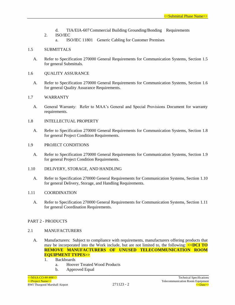
<<Submittal Phase Name>>
<<MAA-CO-##-###>> Technical Specifications
<<Project Name>> 271123 - 2
Telecommunication Room Equipment
BWI Thurgood Marshall Airport <<Date>>
d. TIA/EIA-607 Commercial Building Grounding/Bonding Requirements
2. ISO/IEC
a. ISO/IEC 11801 Generic Cabling for Customer Premises
1.5 SUBMITTALS
A. Refer to Specification 270000 General Requirements for Communication Systems, Section 1.5
for general Submittals.
1.6 QUALITY ASSURANCE
A. Refer to Specification 270000 General Requirements for Communication Systems, Section 1.6
for general Quality Assurance Requirements.
1.7 WARRANTY
A. General Warranty: Refer to MAA’s General and Special Provisions Document for warranty
requirements.
1.8 INTELLECTUAL PROPERTY
A. Refer to Specification 270000 General Requirements for Communication Systems, Section 1.8
for general Project Condition Requirements.
1.9 PROJECT CONDITIONS
A. Refer to Specification 270000 General Requirements for Communication Systems, Section 1.9
for general Project Condition Requirements.
1.10 DELIVERY, STORAGE, AND HANDLING
A. Refer to Specification 270000 General Requirements for Communication Systems, Section 1.10
for general Delivery, Storage, and Handling Requirements.
1.11 COORDINATION
A. Refer to Specification 270000 General Requirements for Communication Systems, Section 1.11
for general Coordination Requirements.
PART 2 - PRODUCTS
2.1 MANUFACTURERS
A. Manufacturers: Subject to compliance with requirements, manufacturers offering products that
may be incorporated into the Work include, but are not limited to, the following: <<DCI TO
REMOVE MANUFACTURERS OF UNUSED TELECOMMUNICATION ROOM
EQUIPMENT TYPES>>
1. Backboards
a. Hoover Treated Wood Products
b. Approved Equal

<<Submittal Phase Name>>
<<MAA-CO-##-###>> Technical Specifications
<<Project Name>> 271123 - 3
Telecommunication Room Equipment
BWI Thurgood Marshall Airport <<Date>>
2. Cabinets and racks:
a. Legrand / Ortronics
b. Chatsworth Products
c. Great Lakes
d. Winstead
e. Approved Equal
3. Enclosures:
a. Hammond Manufacturing
b. nVent/Hoffman
c. XXX
d. Approved Equal
4. Cable Management:
a. Legrand/Ortronics
b. Panduit
c. XXX
d. Approved Equal
5. Termination Equipment:
a. Telephone Copper Cable Termination:
1) CommScope ADC/Krone
2) No Substitutions Allowed
b. CAT Copper Cable Patch Panels
1) Legrand/Ortronics
2) Panduit
3) Approved Equal
c. Fiber Optic Patch Panel
1) Legrand/Ortronics
2) Panduit
3) R&M
4) Approved Equal
6. Ladder Cable Tray:
a. Eaton/B-Line
b. Middle Atlantic
c. XXX
d. Approved Equal
7. Rack Mounted Uninterruptible Power Supply (UPS):
a. APC
b. Eaton
c. Manufacturer 3
d. Approved Equal
8. Power Distribution Units:
a. APC
b. Eaton
c. Liebert
d. Approved Equal
<<Submittal Phase Name>>
<<MAA-CO-##-###>> Technical Specifications
<<Project Name>> 271123 - 4
Telecommunication Room Equipment
BWI Thurgood Marshall Airport <<Date>>
2.2 BACKBOARDS<<DCI TO REMOVE SECTION IF ADDITIONAL BACKBOARDS ARE
NOT INCLUDED IN PROJECT>>
1. Provide plywood backboards in Data Centers, Computer Rooms, Building Entrance
Rooms, and Telecommunication Rooms as shown on the plans:
a. ¾” Fire retardant treated grade plywood
b. Plywood shall have a flame spread rating of 25 or less when tested in accordance
with ASTM E 84, “Standard Test Method for Surface Burning Characteristics of
Building Materials”
c. Interior “Type A” fire retardant treated lumber and plywood with individual surface
burning characteristics for the species and product listed under UL Certifications
d. Plywood shall be stamped with the rating
e. Plywood shall be painted. DCI shall ensure that one rating stamp is visible after
painting and after plywood is mounted. Plywood shall be painted on all 6 sides.
Coordinate off-white, eggshell color with MAA DAT.
2.3 CABINETS AND RACKS
1. Two-Post Open Frame Rack<<DCI TO REMOVE SECTION IF TWO POST RACKS
ARE NOT INCLUDED IN PROJECT>>
a. Provide open frame floor-mount two post racks that support rack mounted
equipment as well as horizontal and vertical cable management.
b. 19-inch EIA-310-D compliant rack mounting rails.
c. Threaded #12-24 Equipment Mounting holes.
d. Dimensions: 84” H x 20” W with 45 usable rack units.
e. Load capacity: 1,500 lbs of equipment.
f. Provide all required hardware to secure cabinet to floor.
g. Finish: powder coat paint in black.
2. Freestanding Equipment Cabinets<<DCI TO REMOVE SECTION IF CABINETS
ARE NOT INCLUDED IN PROJECT>>
a. Cabinets shall be sized according to Project design, with internal vertical and
horizontal cable management.
b. Cabinets shall be 4 post with 19-inch EIA-310-D compliant rack mounting rails.
c. Cabinets shall have minimum dimensions of 29.5 in width, 42 in depth, minimum
45 usable rack units and as shown on the drawings.
d. Cabinets shall be seismic rated with equipment load capacity of 2,000 lbs.
e. Cabinets shall have perforated locking front and rear doors with two-point Cam
Latch locks independently keyed for each cabinet and matching locks for front and
rear doors of a cabinet. Sides and top panels shall be minimum 16 gauge.
f. Cabinets shall have solid top panels with appropriately sized cable openings and
grommets.
g. Cabinets with active equipment shall have multiple fans to exhaust at least 800 CFM
of air for active equipment cabinets.
h. Cabinets shall be provided with blanking panels installed at all open rack unit spaces.
i. Provide seismic kit, casters, leveling feet, and bolt-down stabilization bracket and
seismic bracing below raised floor for each cabinet. Coordinate installation of all
owner furnished seismic protection devices.
j. Adjacent cabinets shall be ganged together using manufacturer kits. One side panel
shall be provided between adjacent cabinets and at each end of the cabinet row.
k. Cabinets and doors shall be black.
<<Submittal Phase Name>>
<<MAA-CO-##-###>> Technical Specifications
<<Project Name>> 271123 - 5
Telecommunication Room Equipment
BWI Thurgood Marshall Airport <<Date>>
2.4 ENCLOSURES
1. Provide enclosures in accordance with the project drawings.
a. Provide enclosures rated and sized as noted in the project drawings.
b. For exterior enclosures, provide the following: <<DCI TO REMOVE SECTION
IF EXTERIOR ENCLOSURES ARE NOT USED IN PROJECT>>
1) NEMA 4X stainless steel enclosures unless noted otherwise.
2) Heater/blower to control the cabinet temperature
3) Provide internal, removable back panel to allow mounting of equipment
4) Provide enclosure with mounting ears
5) For enclosures that will be in exposed locations with direct sun, provide a
solar shield for the enclosure
6) Provide locking hardware in accordance the MAA DAT requirements:
a) Padlock hasp with changeable lock
c. For interior enclosures, provide enclosure type and rating as noted in the contract
documents. <<DCI TO REMOVE SECTION IF INTERIOR ENCLOSURES
ARE NOT USED IN PROJECT>>
1) Provide internal, removable back panel to allow mounting of equipment
2) Provide enclosure with mounting ears
3) Provide locking hardware in accordance the MAA DAT requirements.
2.5 CABLE MANAGEMENT<<DCI TO REMOVE SECTION IF NO CABLE
MANAGEMENT IS NEEDED IN PROJECT>>
1. Horizontal Cable Management: Provide 19-inch rack mountable horizontal wire
management for each copper termination panel, data switching equipment, and as shown
in Drawings.
a. Provide 1 rack unit (RU) of cable management mounted below each 24-port patch
panel.
b. Provide minimum of 2 RU cable management mounted above and below each 48-
port patch panel.
2. Vertical Cable Management Free Standing Equipment Cabinet: Provide vertical wire
management minimum 4 inches wide by 8 inches deep.
3. Vertical Cable Management Open Frame Rack:
a. Provide 6 inch wide by 6 inch deep double sided vertical cable managers on each
side of open frame racks.
b. Cable management shall be provided with cover.
2.6 TERMINATION EQUIPMENT
1. Telephone Copper Cable Termination Equipment<<DCI TO REMOVE SECTION IF
TELEPHONE COPPER TERMINATION EQUIPMENT IS NOT NEEDED IN
PROJECT>>
a. Telephony installations shall be VOIP based. CAT3 and legacy telephony solutions
only permitted with written approval of MAA.
b. Main Distribution Frame
1) Provide wall mount distribution frame with two vertical mounting frames
with 66 slots for modules and label holders
2) Frame shall be able to accommodate up to 1200 pairs if fully populated
3) Frame shall be provided with cable guides for rack entry from top or bottom

<<Submittal Phase Name>>
<<MAA-CO-##-###>> Technical Specifications
<<Project Name>> 271123 - 6
Telecommunication Room Equipment
BWI Thurgood Marshall Airport <<Date>>
4) Frame shall be provided with horizontal jumper capacity of approximately
4000 pairs and vertical capacity of approximately 600 pairs
5) Frame shall be able to accept either 8 or 10 pair modules
a) 8 pair modules shall be used for station cables
b) 10 pair modules shall be used for backbone cables
c. Modules
1) Provide eight or ten modules with disconnection points for opening the line,
testing in both directions or insertion of graded protection elements
2) Modules shall be designed to mount on the Main Distribution Frame
3) Modules shall be suitable for all xDSL circuits
4) Modules shall support overvoltage protection equipment
5) Provide module type and quantities per the drawings
6) Provide protection modules for all cable pairs terminated.
2. CAT Copper Cable Termination Equipment<<DCI TO REMOVE SECTION, OR
UNUSED PATCH PANEL TYPES IF NOT NEEDED IN PROJECT>>
a. 24 Port Category 6A Patch Panel
1) Compliant to EIA/TIA Category 6A performance requirements
2) 1 RU in height for mounting in standard 19” rack or cabinet.
3) Four 6 port modules
4) Universally wired 110 termination that support T568A and T568B installs.
5) Patch panel shall have rear cable management supports.
6) High density design that maximizes rack utilization
7) Each port shall be individually numbered and space provided for labeling
below the port.
b. 48 Port Patch Panel
1) Compliant to EIA/TIA Category 6A performance requirements
2) 2 RU in height for mounting in standard 19” rack or cabinet.
3) Eight 6 port modules
4) Universally wired 110 termination that support T568A and T568B installs.
5) Patch panel shall have rear cable management supports.
6) High density design that maximizes rack utilization
7) Each port shall be individually numbered, and space provided for labeling
below the port.
3. Fiber Termination Equipment<<DCI TO REMOVE SECTION, OR UNUSED
EQUIPMENT TYPES IF NOT NEEDED IN PROJECT>>
a. Fiber Patch Panel
1) The fiber patch panel enclosure shall accommodate no less than 12 modules,
with the capacity of not less than 144 strands per 4 RU enclosures if populated
with 12 port modules.
2) Provide patch panel enclosure designed for mounting in standard 19” rack or
cabinet.
3) High density design that maximizes rack utilization
4) Provide blanking adapter plates to cover all unused spaces as necessary.
5) Each patch panel shall allow any individual element to be terminated or
otherwise handled without disturbing or damaging other strands.
6) Patch panel enclosure shall include a directory attached to the unit front door.
7) Modules shall include:
<<Submittal Phase Name>>
<<MAA-CO-##-###>> Technical Specifications
<<Project Name>> 271123 - 7
Telecommunication Room Equipment
BWI Thurgood Marshall Airport <<Date>>
a) Module shall be available with ST, SC, or LC adapters. LC adaptors
are by DAT approval only.
b) Module shall be provided with color-coded pigtails for splicing to
incoming fiber.
c) Each module shall provide either compression glands or internal clips
and entrapment of yarn-based impact resistance to provide strain relief.
d) Each module shall provide fiber handling for fiber strands, including
20" fiber reserve (service loop) inside the module housing with no
bends sharper than 2" bend radius.
e) The module shall be removable without the use of tools, and shall
include a clear, removable cover to allow for inspection of the fibers.
b. Fiber Splice
1) Fiber splice enclosure tray designed for mounting in standard 19” rack or
cabinet and not less than 17” of depth.
2) Each splice tray within enclosure shall be able to accommodate up to 48
individual fibers.
3) Each splice tray shall provide multiple captive and non-captive cable entrance
holes.
4) Fiber splice unit shall incorporate multiple fixed tie down points.
5) Fiber splice enclosure shall be available in 2RU/3RU/4RU versions.
2.7 LADDER CABLE TRAY<<DCI TO REMOVE SECTION IF CABLE TRAY IS NOT
NEEDED IN PROJECT>>
A. Ladder Tray:
1. Ladder tray shall be provided with straight sections and pre-made fittings as needed for
complete ladder tray system.
2. Straight ladder sections shall be provided with the following:
a. Compliance: EIA/TIA 310D.
b. UL Classified: US and Canada.
c. Ladder Section Dimensions:
1) Length: As required per the plans
d. Width: minimum 12 inches.
e. Thickness: 1.5 inches.
f. Rungs:
1) Dimensions: 1 inch by 0.5 inch.
2) Spacing: on 9-inch centers maximum.
g. Construction: Fully welded.
h. Weight Capacity: 187 pounds per foot, based on 4-foot support span.
i. Material: Structural steel.
j. Rungs: 11-gauge.
k. Ladders: 16-gauge.
l. Finish: Two layers, black powder coat.
3. Provide splice hardware, wall, suspension, middle, and end support hardware, 90-degree
bend fittings, and Tee fittings/Tee splice hardware as required per the configuration as
shown on the plans.
<<Submittal Phase Name>>
<<MAA-CO-##-###>> Technical Specifications
<<Project Name>> 271123 - 8
Telecommunication Room Equipment
BWI Thurgood Marshall Airport <<Date>>
4. Provide accessories as required including, but not limited to, end caps, ceiling hang kits,
supports, clamps, grounding accessories, cable spools/waterfalls, etc.
2.8 RACK MOUNTED UNINTERRUPTIBLE POWER SUPPLY<<DCI TO CONFIRM UPS
POWER AVAILABLITY AND REMOVE SECTION IF UPS IS NOT NEEDED IN
PROJECT>>
1. All UPS units shall be Eaton UPS units unless authorized by the Airport in writing.
2. Provide a rack mount UPS for each system rack/cabinet illustrated with a UPS unit in the
Drawings. See Drawings for proposed UPS sizes and quantities.
3. Minimum specifications:
a. Bypass: Internal bypass (automatic and manual)
b. Batteries: Batteries shall be a maintenance-free, sealed Lead-Acid battery with
suspended electrolyte; leak proof, as required for 15 minute back- up minimum.
c. UPS Expansion: The UPS units provided shall be able to be expanded for additional
run time by adding external battery cabinets. The battery cabinets shall be modular
in nature and shall extend the UPS runtime as additional load is added (up to the
UPS rated capacity).
4. Interface Requirements: UPS shall contain one (1) 10/100 Ethernet port for LAN interface
5. Free (Dry) Contacts (Internal to UPS or available as I/O Card) or SNMP alarms:
a. The UPS is on battery
b. The UPS is on battery and the remaining battery capacity is low
c. The UPS is off
d. The battery needs to be replaced
e. The UPS is in bypass
f. The UPS is overloaded
g. The UPS is in fault state
6. Controls: Multi-function LCD status and control console/indicator lights to provide
indication of the following:
a. Load Level
b. Battery Charge Level
c. On-Line
d. Overload
e. On Battery
f. Disconnected Battery/Replace Battery
g. High/Low Voltage
7. UPS Capacity: Provide UPS units sized per the plans and based on the expected loads at
each cabinet. The calculations shall be submitted to MAA DAT for review and approval
prior to ordering the UPS. The UPS inverter shall not be loaded beyond 50% maximum
capacity per the calculations, and the UPS shall be capable of having batteries added to
achieve the required run times up to 80% of the inverter capacity. At a minimum, provide
a 1.4 kVA unit. See plans for UPS sizes and locations.
8. Alarms: Alarm when on battery; distinctive low battery alarm; power fail; configurable
delays
a. Power Off: Emergency power off
9. Physical: All UPS components shall be rack mountable up to 6 KVA, then floor mounted
units may be allowed per the guidelines.
10. Regulatory: CSA, FCC Part 15 Class A, UL 1778, Energy Star Qualified
11. On line operation: The UPS shall provide continuous, no break power during complete
power loss or momentary interruption
<<Submittal Phase Name>>
<<MAA-CO-##-###>> Technical Specifications
<<Project Name>> 271123 - 9
Telecommunication Room Equipment
BWI Thurgood Marshall Airport <<Date>>
12. Output protection: Current limiting
13. Input protection: DC fuse and battery charger fuse
14. Environmental:
a. Operating Temperature: 32 to 104 degree F
b. Relative Humidity: 0% to 95%, non-condensing
15. Provide unattended shutdown software to provide for automatic, unattended shut down of
connected servers during an extended power failure.
16. Power Input: Provided twist-lock (preferred) power cords as required to match the
appropriate UPS model and source receptacles.
17. Power Output: Provide receptacles to match the PDU plugs types.
2.9 POWER DISTRIBUTION UNITS<<DCI TO REMOVE SECTION IF PDUs NOT NEEDED
IN PROJECT>>
A. Power Distribution Units (PDUs): 120V Single-Phase
1. Input Power: Each PDU shall be rated for 20A at 120 VAC, single-phase.
2. Input Connector: (1) 10 foot, NEMA L5-20P cord.
3. Output Power: 120VAC
4. Output Connector: (24) NEMA 5-20R
5. Dimensions: Minimum length of 63 inches and complies with UL 60950.
6. Each unit shall be unswitched to prevent accidental power down of equipment.
7. Each unit shall have integral surge protection, resettable.
8. Confirm quantity of PDUs to be provided with the design.
B. Power Distribution Units (PDUs): 208V Three-Phase
1. Input Power: Each PDU shall be rated for 5.7kW at 208 VAC, 3-phase.
2. Input Connector: (1) 10 foot, ground locking type NEMA L21-20P cord.
3. Output Power: 120VAC, 208VAC
4. Output Connector: (21) NEMA 5-20R, and (6) NEMA L6-20R
5. Dimensions: Minimum length of 70 inches and UL 60950 compliant.
6. Each unit shall be unswitched to prevent accidental power down of equipment.
7. Each unit shall have integral surge protection, resettable.
PART 3 - EXECUTION
3.1 EXAMINATION
A. Refer to Specification 270000 General Requirements for Communication Systems, Section 3.1
for general Examination Requirements.
B. In addition, the following applies:
1. Field verify the communication room layouts and document all existing racks, cabinets,
and enclosures as well as with other equipment in the room. Field verify the clearances for
all of the equipment prior to adding any racks or enclosures. If any issues are noted, the
issues shall be brought to the attention of DAT for resolution prior to installing any
equipment.

<<Submittal Phase Name>>
<<MAA-CO-##-###>> Technical Specifications
<<Project Name>> 271123 - 10
Telecommunication Room Equipment
BWI Thurgood Marshall Airport <<Date>>
3.2 INSTALLATION
A. Refer to Specification 270000 General Requirements for Communication Systems, Section 3.2
for general Installation Requirements.
B. In addition, the following applies:
1. Provide rack as shown on the Drawings and as specified in this section.
2. Provide all mounting components and accessories to securely fix racks to floor and
supporting walls.
3. Provide overhead ladder rack either fixed to the top of each rack and running from the top
of the rack to the telephone backboard where the feeder and distribution cables run, or
supported above with ½ inch all-thread rod supports, as shown on the drawings.
4. Provide cable bend management fixtures to maintain the proper bend radius as the cables
drop into the rack. Do not allow cables to be unsupported beyond 2 feet as they run from
conduit or cable tray to equipment cabinets.
5. Racks shall be seismically braced in accordance with local seismic bracing requirements.
Racks shall be braced against sway on all three axes.
6. Horizontal cable tray or other cable support that is also rated as a seismic brace may be
used to meet some of the seismic bracing requirements.
7. Provide patch management ring runs in each rack. Provide (1) 2U high horizontal patch
management between each panel of each rack.
8. Provide side-mounted vertical cable management with covers on both sides of each rack.
The cable management shall be with cover plates and bracket kits as needed to attach to
adjacent racks.
9. Provide strain relief and cable management at the rear of each data panel to ensure uniform
routing of all feeder and distribution cables.
10. The rack shall be manufactured from extruded aluminum and marked with Rack Unit
spacing.
11. Provide all racks with grounding kits and wires.
12. Provide Raised Floor Rack Supports from rack manufacturer for all equipment racks
mounted on raised “access” floor in the Data Center. Racks installed on raised floors are
to be bolted through the raised floor directly into the concrete flooring below.
13. The rack system solution shall provide integral cable management including vertical
channels, pass through holes and slots for additional cable management accessories.
14. Pass through holes shall be located on the front, back and side of the rack for maximum
flexibility.
15. Racks are to be threaded for #12-24 threads.
16. DAT to make final determination on rack type/manufacture, Cable management and
placement within each communication room.
17. Provide Horizontal Wire Managers above and below each data patch panel.
3.3 DOCUMENTATION
A. Refer to Specification 270000 General Requirements for Communication Systems, Section 3.3
for general Documentation Requirements.
3.4 GENERAL TESTING REQUIREMENTS
A. Refer to Specification 270000 General Requirements for Communication Systems, Section 3.4
for general Testing Requirements.
<<Submittal Phase Name>>
<<MAA-CO-##-###>> Technical Specifications
<<Project Name>> 271123 - 11
Telecommunication Room Equipment
BWI Thurgood Marshall Airport <<Date>>
3.5 FACTORY ACCEPTANCE TESTING
A. Refer to Specification 270000 General Requirements for Communication Systems, Section 3.5
for general Factory Acceptance Testing Requirements.
3.6 INTEGRATION TESTING
A. Refer to Specification 270000 General Requirements for Communication Systems, Section 3.6
for general Integration Testing Requirements.
3.7 ENDURANCE TESTING
A. Refer to Specification 270000 General Requirements for Communication Systems, Section 3.7
for general Endurance Testing Requirements.
3.8 MAINTENANCE AND SUPPORT
A. Refer to Specification 270000 General Requirements for Communication Systems, Section 3.8
for general Maintenance and Support Requirements.
3.9 CLEANING
A. Refer to Specification 270000 General Requirements for Communication Systems, Section 3.9
for general Cleaning Requirements.
3.10 TRAINING
A. Refer to Specification 270000 General Requirements for Communication Systems, Section 3.10
for general Training Requirements.
3.11 FIELD QUALITY CONTROL
A. Refer to Specification 270000 General Requirements for Communication Systems, Section 3.11
for general Field Quality Control Requirements.
3.12 ACCEPTANCE
A. Refer to Specification 270000 General Requirements for Communication Systems, Section 3.12
for general Acceptance Requirements.
END OF SECTION 270123
<<Submittal Phase Name>>
<<MAA-CO-##-###>> Technical Specifications
<<Project Name>> 271300 - 1
Backbone Cabling
BWI Thurgood Marshall Airport <<Date>>
SECTION 271300 – BACKBONE CABLING
PART 1 - GENERAL
1.1 SUMMARY
A. Drawings and general provisions of the Contract, including Terms of Reference and all
contractual conditions apply to this Section.
B. Specification Section 271300 contains the requirements applicable to Backbone Cabling, which
includes both Copper Backbone Cabling and Fiber Optic Backbone Cabling. The Backbone Cable
Subsystem in a building is the part of the premises distribution system that provides connection
between equipment rooms, telecommunication rooms, and telecommunications service entrance
facilities. The backbone subsystem provides either intra-building connections between floors in
multi-story buildings or inter-building connections in campus-like environments.
1. Copper Backbone Cabling: The copper backbone cabling is comprised of high pair count
copper cables that provide telephone connectivity.
2. Fiber Optic Backbone Cabling: The fiber optic backbone cabling is comprised of fiber
optic cabling, both multimode and singlemode cabling, the provides data connectivity
between the communication rooms for airport and tenant connectivity.
1.2 RELATED DOCUMENTS
A. Refer to Specification 270000 General Requirements for Communication Systems, Section 1.2
for Related Sections.
1.3 SCOPE OF WORK
A. Refer to Specification 270000 General Requirements for Communication Systems, Section 1.3
for general Scope of Work.
B. In addition, the following applies:
1. The backbone cabling includes copper and fiber backbone cabling as well as the
termination and testing of the cabling.
1.4 REFERENCES
A. Refer to Specification 270000 General Requirements for Communication Systems, Section 1.4
for general References.
B. In addition, the following references apply:
1. TIA/EIA
a. TIA/EIA-568-B - Commercial Building Telecommunications Cabling Standard
b. TIA/EIA-569-A - Commercial Building Standard for Telecom Pathways and Spaces
c. TIA/EIA-606 - Administration Standard for the Telecommunications Infrastructure
of Commercial Buildings
d. TIA/EIA-607 - Commercial Building Grounding/Bonding Requirements
2. ISO/IEC
CONTENTS OF SPECIFICATION ARE DIVISION OF
AIRPORT TECHNOLOGY (DAT) STANDARDS. DCI
SHALL MAKE ALL REQUIRED, PROJECT
SPECIFIC REVISIONS IN MS WORD TRACK
CHANGES FOR APPROVAL BY DAT.
<<Submittal Phase Name>>
<<MAA-CO-##-###>> Technical Specifications
<<Project Name>> 271300 - 2
Backbone Cabling
BWI Thurgood Marshall Airport <<Date>>
a. ISO/IEC 11801 - Generic Cabling for Customer Premises
1.5 SUBMITTALS
A. Refer to Specification 270000 General Requirements for Communication Systems, Section 1.5
for general Submittals.
1.6 QUALITY ASSURANCE
A. Refer to Specification 270000 General Requirements for Communication Systems, Section 1.6
for general Quality Assurance Requirements.
1.7 WARRANTY
A. General Warranty: Refer to MAA’s General and Special Provisions Document for warranty
requirements.
1.8 INTELLECTUAL PROPERTY
A. Refer to Specification 270000 General Requirements for Communication Systems, Section 1.8
for general Project Condition Requirements.
1.9 PROJECT CONDITIONS
A. Refer to Specification 270000 General Requirements for Communication Systems, Section 1.9
for general Project Condition Requirements.
1.10 DELIVERY, STORAGE, AND HANDLING
A. Refer to Specification 270000 General Requirements for Communication Systems, Section 1.10
for general Delivery, Storage, and Handling Requirements.
1.11 COORDINATION
A. Refer to Specification 270000 General Requirements for Communication Systems, Section 1.11
for general Coordination Requirements.
PART 2 - PRODUCTS
2.1 MANUFACTURERS
A. Manufacturers: Subject to compliance with requirements, manufacturers offering products that
may be incorporated into the Work include, but are not limited to, the following: <<DCI TO
REMOVE MANUFACTURERS OF UNUSED PRODUCT TYPES>>
1. Backbone Copper Cable
a. Belden
b. Panduit
c. Superior Essex
d. Approved Equal
2. Backbone Fiber Optic Cable

<<Submittal Phase Name>>
<<MAA-CO-##-###>> Technical Specifications
<<Project Name>> 271300 - 3
Backbone Cabling
BWI Thurgood Marshall Airport <<Date>>
a. CommScope
b. Corning
c. General Cable
d. Approved Equal
2.2 PRODUCTS
A. Backbone Copper Cable<<DCI TO REMOVE SECTION IF NO COPPER CABLES ARE
USED IN PROJECT>>
1. Provide Cat 3 rated backbone copper cabling
2. Provide Cat 3 rated backbone cabling in pair counts as noted on the plans and block/riser
diagrams.
3. Cable jacket rating shall match the installation for the specific cable, with riser rated used
for conduits to be installed in conduit and plenum rated for cabling to be installed in cable
tray. For cabling that will be routed in a mixed pathway, the higher rating requirement shall
apply.
4. Cable shall have the following characteristics:
a. 24 AWG solid copper conductors
b. Individual conductors shall be provided with PVC insulation, color coded
c. Cable shall be rated at up to 300 Volts
d. Cable shall be rated for an operating temperature of -22°F to 140°F
e. Cable shall be ICEA S-90-661-2012, NEMA WC-63.1, and TIA/EIA ANSI/TIA-
568.2-D Category 3 compliant
5. All Cat 3 cable shall be terminated on DAT approved termination equipment as required
in Specification 271123, Section 2.6.1 Telephone copper cable terminations
B. Backbone Fiber Optic Cable <<DCI TO REMOVE SECTION IF NO FIBER OPTIC
CABLES ARE USED IN PROJECT>>
1. All backbone fiber optic cables shall be provided with the following:
a. Cable jacket rating shall match the installation for the specific cable, with riser rated
(CMR) used for conduits to be installed in conduit and plenum rated for cabling to
be installed in cable tray. For cabling that will be routed in a mixed pathway, the
higher rating requirement shall apply.
b. Provide printed length markings on the cable jacket every two feet.
c. All fiber will be installed in a 1 1/4 -inch inner duct within the conduit.
d. Optical fibers will be contained within loose buffer tubes. The cable will be an all-
dielectric construction, with a central strength member.
e. All fibers shall be terminated and tested unless otherwise noted on the plans.
f. Provide fiber termination panels, patch panels, and splice enclosures as required to
properly terminate all fiber strands. Refer to Specification 271123 for fiber
termination, patch, and splice enclosure specifications.
C. Multimode Fiber Optic Cable <<DCI TO REMOVE SECTION IF MULTIMODE FIBER
CABLES ARE NOT USED IN PROJECT>>
1. Multimode fiber optic cabling is only allowed on a project for special purposes as approved
in writing by MAA DAT. If multimode cable is to be provided, the cable shall conform to
the following.
2. Provide multimode fiber optic cable with strand counts as noted on the plans and
block/riser diagrams.

<<Submittal Phase Name>>
<<MAA-CO-##-###>> Technical Specifications
<<Project Name>> 271300 - 4
Backbone Cabling
BWI Thurgood Marshall Airport <<Date>>
3. Cable shall have the following characteristics:
a. 50-micron core, laser optimized (OM4)
b. Outer jacket shall be aqua in color
c. Fibers shall be grouped into 12 strand bundles (tubes) and each tube shall be color
coded
d. Each fiber within each tube shall be provided with a colored jacket.
e. Fiber shall be indoor rated and have a 32°F to 140°F installation temperature and an
operational temperature from 32°F to 158°F.
f. Cable shall be loose tube design
g. Maximum attenuation shall be 3.0 dB/km @ 850 nm and 1.0 dB/km @ 1300 nm.
4. Multimode optical fiber connectors:
a. ST connectors
D. Singlemode Fiber Optic Cable<<DCI TO REMOVE SECTION IF SINGLEMODE FIBER
CABLES ARE NOT USED IN PROJECT>>
1. Provide singlemode fiber optic cable with strand counts as noted on the plans and
block/riser diagrams.
2. Cable shall have the following characteristics:
a. 8.3-micron core (OS2)
b. Outer jacket shall be yellow in color
c. Fibers shall be grouped into 12 strand bundles (tubes) and each tube shall be color
coded
d. Each fiber within each tube shall be provided with a colored jacket.
e. Fiber shall be indoor rated and have a 32°F to 140°F installation temperature and an
operational temperature from 32°F to 158°F.
f. Cable shall be loose tube design
g. Maximum attenuation shall be 0.4 dB/km @ 1310 nm and 0.3 dB/km @ 1510 nm.
h. Cable shall be capable of supporting 1470, 1490, 1510, 1530, 1550, 1570, 1590 and
1610 nm wavelengths.
3. Singlemode optical fiber connectors:
a. Provide SC type connectors with fusion spliced terminations.
b. Insertion loss of mated pair at 1310 nm to be less than 0.5 dB at acceptance for every
duplex connector.
c. Optimally keyed, allowing reproducible mating conditions each time a connection
is made between connector and coupler.
d. Fitted with strain relief boots to ensure durable and robust connections
e. Durability better than 500 matings, with a maximum increase in insertion loss of not
more than 0.2 dB.
f. Fitted with a tight polymer cap over the connector to prevent ingress of dirt and dust,
until the connector is fitted to a coupler.
PART 3 - EXECUTION
3.1 EXAMINATION
A. Refer to Specification 270000 General Requirements for Communication Systems, Section 3.1
for general Examination Requirements.
B. In addition, the following applies:

<<Submittal Phase Name>>
<<MAA-CO-##-###>> Technical Specifications
<<Project Name>> 271300 - 5
Backbone Cabling
BWI Thurgood Marshall Airport <<Date>>
1. Field verify the backbone cable pathway and verify capacity is available and proper bend
radius will be maintained using any existing pathways. Should any issues be noted, bring
these issues to the attention of DAT prior to starting the installation.
3.2 INSTALLATION
A. Refer to Specification 270000 General Requirements for Communication Systems, Section 3.2
for general Installation Requirements.
B. The following applies for backbone copper cables: <<DCI TO REMOVE SECTION IF
BACKBONE COPPER CABLES ARE NOT USED IN PROJECT>>
1. Slack cable shall be coiled on the wall above the termination points as required to provide
a neat and workmanlike installation.
a. 12’ of slack cable shall be routed to above cable tray and coiled on wall. If ceiling
height does not permit slack coil above tray, coordinate slack coil location with
MAA.
2. Provide strain relief for the cable and sufficient slack so that terminations do not exert force
on the terminations.
3. Where possible, cable terminations shall be fed from above to the termination blocks.
C. The following applies for backbone fiber cables: <<DCI TO REMOVE SECTION IF FIBER
OPTIC CABLES ARE NOT USED IN PROJECT>>
1. 12’ of slack cable shall be neatly routed to above cable tray and coiled on wall. If ceiling
height does not permit slack coil above tray, coordinate slack coil location with MAA.
a. 3’ of fiber slack to be coiled within fiber module or enclosure.
2. Each cable shall be individually attached to the respective fiber enclosure by mechanical
means. The cables strength member shall be securely attached the cable strain relief bracket
in the enclosure.
3. Each fiber bundle shall be stripped upon entering the splice module
4. Each cable shall be clearly labeled at the entrance to the splice enclosure. Cables labeled
within the bundle shall not be acceptable.
5. A maximum of 12 strands of fiber shall be spliced in each module
6. All spare strands shall be installed into spare splice trays.
3.3 DOCUMENTATION
A. Refer to Specification 270000 General Requirements for Communication Systems, Section 3.3
for general Documentation Requirements.
B. In addition, the following applies:
1. Provide test results for all backbone infrastructure provided.
3.4 GENERAL TESTING REQUIREMENTS
A. Refer to Specification 270000 General Requirements for Communication Systems, Section 3.4
for general Testing Requirements.
B. The following applies for backbone copper cable testing: <<DCI TO REMOVE SECTION IF
BACKBONE COPPER CABLES ARE NOT USED IN PROJECT>>
<<Submittal Phase Name>>
<<MAA-CO-##-###>> Technical Specifications
<<Project Name>> 271300 - 6
Backbone Cabling
BWI Thurgood Marshall Airport <<Date>>
1. Test each Telephone System Backbone Cable and its associated patch frame connectors.
Carry out the following tests on every pair of every telephone system feeder and external
cable:
a. Conductor Continuity
b. Conductor Separation
c. Conductor Polarity
C. The following applies for fiber optic cable testing: <<DCI TO REMOVE SECTION IF FIBER
OPTIC CABLES ARE NOT USED IN PROJECT>>
1. All cables and termination hardware shall be 100% tested for defects in installation and to
verify cabling system performance under installed conditions per the requirements of
ANSI/TIA/EIA-568-B, TSB-67 and TSB-155.
2. All strands of each installed cable shall be verified prior to system acceptance. Any defect
in the cabling system installation including but not limited to cable, connectors, feed
through couplers, patch panels, and connector blocks shall be repaired or replaced in order
to ensure 100% useable conductors in all cables installed.
3. Test each optical fiber cable element and its associated connectors. Carry out the following
test on every element of every optical fiber cable:
a. Visually check optical connectors using microscope (minimal magnification x200)
to ensure that no physical damage has occurred during the installation process. There
are to be no scratches on the core of the fiber or pits on the core or cladding. If any
defect cannot be rectified with polishing, the connector is to be replaced.
b. Carry out OTDR tests on all strands at 850/1300 nm for multimode and 1310/1550
nm for single mode. These tests shall be carried out using a near end launch lead and
a far end drop lead.
4. The number of samples (averages) for each OTDR test shall be such that the noise
amplitude is significantly less than the smallest loss of any component under test. This may
vary for different cable runs, for shorter runs and fusion splices etc.; it may be necessary
to run many samples.
5. Verify the labeling of the cable and connectors is correct.
6. If any strand has an excessive attenuation coefficient, a sudden step in attenuation
coefficient (greater than 0.2 dB) or back scatter, losses due to micro bending or macro
bending or has any other fault then the fault on that element shall be rectified.
7. The attenuation of each mode connector shall be measured in both directions.
8. Each fusion splice shall be tested in both directions for all strands. The measurements for
each direction shall be averaged for the final attenuation figure for each fusion splice.
9. The return loss must be measured in both directions for single mode connectors. The return
loss shall be greater or equal to the value shown in the table above.
10. Any failures shall be recorded, and the results obtained after rectification of the fault shall
be recorded.
11. Provide electronic copies of the OTDR traces to the Owner on completion of the testing.
Provide a copy of the emulation software and the appropriate license to the client.
12. All fiber testing shall be performed on all fibers in the completed end-to-end system. There
shall be no splices unless clearly defined in the contract documents or as allowed in writing
by DAT. Testing shall consist of an end-to-end power meter test performed per TIA/EIA-
455-53A for all station fiber. These tests also include continuity checking of each fiber.
Prior to testing a sample shall be given to DAT for approval.
<<Submittal Phase Name>>
<<MAA-CO-##-###>> Technical Specifications
<<Project Name>> 271300 - 7
Backbone Cabling
BWI Thurgood Marshall Airport <<Date>>
3.5 FACTORY ACCEPTANCE TESTING
A. Refer to Specification 270000 General Requirements for Communication Systems, Section 3.5
for general Factory Acceptance Testing Requirements.
3.6 INTEGRATION TESTING
A. Refer to Specification 270000 General Requirements for Communication Systems, Section 3.6
for general Integration Testing Requirements.
3.7 ENDURANCE TESTING
A. Refer to Specification 270000 General Requirements for Communication Systems, Section 3.7
for general Endurance Testing Requirements.
3.8 MAINTENANCE AND SUPPORT
A. Refer to Specification 270000 General Requirements for Communication Systems, Section 3.8
for general Maintenance and Support Requirements.
3.9 CLEANING
A. Refer to Specification 270000 General Requirements for Communication Systems, Section 3.9
for general Cleaning Requirements.
3.10 TRAINING
A. Refer to Specification 270000 General Requirements for Communication Systems, Section 3.10
for general Training Requirements.
3.11 FIELD QUALITY CONTROL
A. Refer to Specification 270000 General Requirements for Communication Systems, Section 3.11
for general Field Quality Control Requirements.
3.12 ACCEPTANCE
A. Refer to Specification 270000 General Requirements for Communication Systems, Section 3.12
for general Acceptance Requirements.
END OF SECTION 271300

<<Submittal Phase Name>>
<<MAA-CO-##-###>> Technical Specifications
<<Project Name>> 271400 - 1
Outside Plant Cable
BWI Thurgood Marshall Airport <<Date>>
SECTION 271400 – OUTSIDE PLANT CABLING
PART 1 - GENERAL
1.1 SUMMARY
A. Drawings and general provisions of the Contract, including Terms of Reference and all
contractual conditions apply to this Section.
B. Specification Section 271400 contains the requirements applicable to Outside Plant (OSP)
Cabling. OSP cabling is cable that is rated for the implementation in ductbanks and conduits
exterior to buildings or below grade in buried applications. These cables are designed to provide
a higher level of protection from moisture infiltration as well as resistance to corrosion, chemicals,
and other aspects typically found in OSP applications.
C. The OSP Cabling subsystem provides inter-building connections in campus-like environments
and connections to site facilities and site equipment locations. OSP cabling is typically comprised
of backbone cabling as well as horizontal cabling including the following:
1. OSP Copper Backbone Cabling: The OSP copper backbone cabling is comprised of high
pair count copper cables that provide telephone connectivity.
2. OSP Fiber Optic Backbone Cabling: The OSP fiber optic backbone cabling is comprised
of fiber optic cabling, both multimode and singlemode cabling, the provides data
connectivity between the communication rooms for airport and tenant connectivity.
3. OSP Horizontal Cabling: The OSP horizontal cabling is comprised of any copper or fiber
cabling that would be routed to field equipment from adjacent buildings or from equipment
enclosures.
1.2 RELATED DOCUMENTS
A. Refer to Specification 270000 General Requirements for Communication Systems, Section 1.2
for related sections.
1.3 SCOPE OF WORK
A. Refer to Specification 270000 General Requirements for Communication Systems, Section 1.3
for general Scope of Work.
B. In addition, the following applies:
1. <<Add scope specific to this section>>
1.4 REFERENCES
A. Refer to Specification 270000 General Requirements for Communication Systems, Section 1.4
for general References.
B. In addition, the following references apply:
1. TIA/EIA
a. TIA/EIA-568-B - Commercial Building Telecommunications Cabling Standard
b. TIA/EIA-569-A - Commercial Building Standard for Telecom Pathways and Spaces
CONTENTS OF SPECIFICATION ARE DIVISION OF
AIRPORT TECHNOLOGY (DAT) STANDARDS. DCI
SHALL MAKE ALL REQUIRED, PROJECT
SPECIFIC REVISIONS IN MS WORD TRACK
CHANGES FOR APPROVAL BY DAT.
<<Submittal Phase Name>>
<<MAA-CO-##-###>> Technical Specifications
<<Project Name>> 271400 - 2
Outside Plant Cable
BWI Thurgood Marshall Airport <<Date>>
c. TIA/EIA-606 - Administration Standard for the Telecommunications Infrastructure
of Commercial Buildings
d. TIA/EIA-607 - Commercial Building Grounding/Bonding Requirements
2. ISO/IEC
a. ISO/IEC 11801 - Generic Cabling for Customer Premises
1.5 SUBMITTALS
A. Refer to Specification 270000 General Requirements for Communication Systems, Section 1.5
for general Submittals.
1.6 QUALITY ASSURANCE
A. Refer to Specification 270000 General Requirements for Communication Systems, Section 1.6
for general Quality Assurance Requirements.
1.7 WARRANTY
A. General Warranty: Refer to MAA’s General and Special Provisions Document for warranty
requirements.
1.8 INTELLECTUAL PROPERTY
A. Refer to Specification 270000 General Requirements for Communication Systems, Section 1.8
for general Project Condition Requirements.
1.9 PROJECT CONDITIONS
A. Refer to Specification 270000 General Requirements for Communication Systems, Section 1.9
for general Project Condition Requirements.
1.10 DELIVERY, STORAGE, AND HANDLING
A. Refer to Specification 270000 General Requirements for Communication Systems, Section 1.10
for general Delivery, Storage, and Handling Requirements.
1.11 COORDINATION
A. Refer to Specification 270000 General Requirements for Communication Systems, Section 1.11
for general Coordination Requirements.
PART 2 - PRODUCTS
2.1 MANUFACTURERS
A. Manufacturers: Subject to compliance with requirements, manufacturers offering products that
may be incorporated into the Work include, but are not limited to, the following: <<DCI TO
REMOVE MANUFACTURERS OF UNUSED CABLING TYPES>>
1. OSP Backbone Copper Cable
a. Belden
<<Submittal Phase Name>>
<<MAA-CO-##-###>> Technical Specifications
<<Project Name>> 271400 - 3
Outside Plant Cable
BWI Thurgood Marshall Airport <<Date>>
b. Superior Essex
c. Approved Equal
2. OSP Backbone Fiber Optic Cable
a. CommScope
b. Corning
c. General Cable
d. Approved Equal
3. OSP Horizontal Cable
a. Belden
b. CommScope
c. Corning
d. General Cable
e. Superior Essex
f. Approved Equal
B. Backbone Copper OSP Cable<<DCI TO REMOVE SECTION IF NO ADDITIONAL
BACKBONE COPPER CABLES ARE USED IN PROJECT>>
1. Provide Cable listed as suitable for direct-burial or below grade conduit applications for
installation in an underground duct or conduit system. The cable shall be provided with:
a. 24 AWG solid annealed copper conductors with pair counts per the project plans
and riser/block diagrams.
b. Sheath shall consist of a 0.008" corrugated aluminum shield, with a 0.006"
corrugated steel shield and a black polyethylene jacket.
c. Jacket shall be sequentially printed with a footage marker at regular intervals.
d. A flooding compound shall be applied over the core and to all surfaces of the
aluminum and steel shields to resist moisture entry and to inhibit corrosion.
e. Terminate both ends of this cable on approved protection blocks. Refer to
Specification 271123, Section 2.6.1 Telephone copper cable terminations.
C. Backbone Fiber Optic OSP Cable<<DCI TO REMOVE SECTION IF NO ADDITIONAL
BACKBONE FIBER CABLES ARE USED IN PROJECT>>
1. Provide Cable listed as suitable for direct-burial or below grade conduit applications for
installation in an underground duct or conduit system. The cable shall be provided with:
a. Provide printed length markings on the cable jacket every two feet.
b. All fiber will be installed in a 1 1/4 -inch inner duct within the conduit.
c. Optical fibers will be contained within loose buffer tubes. The cable will be an all-
dielectric construction, with a central strength member.
d. All fibers shall be terminated and tested unless otherwise noted on the plans.
e. Provide fiber termination panels, patch panels, and splice enclosures as required to
properly terminate all fiber strands. Refer to 271123 for fiber termination, patch, and
splice enclosure specifications.
2. OSP Multimode Fiber Optic Cable <<DCI TO REMOVE SECTION IF NO
ADDITIONAL MULTIMODE FO CABLES ARE USED IN PROJECT>>
a. Multimode fiber optic cabling is only allowed on a project for special purposes as
approved in writing by MAA DAT. If multimode cable is to be provided, the cable
shall conform to the following.
b. Provide multimode fiber optic cable with strand counts as noted on the plans and
block/riser diagrams.
c. Cable shall have the following characteristics:
<<Submittal Phase Name>>
<<MAA-CO-##-###>> Technical Specifications
<<Project Name>> 271400 - 4
Outside Plant Cable
BWI Thurgood Marshall Airport <<Date>>
1) 50-micron core, laser optimized (OM4)
2) Outer jacket shall be rated for OSP or direct buried rated
3) Fibers shall be grouped into 12 strand bundles (tubes) and each tube shall be
color coded
4) Each fiber within each tube shall be provided with a colored jacket.
5) Fiber shall be OSP/outdoor rated and have a -22°F to 158°F installation
temperature and an operational temperature from -40°F to 158°F.
6) Cable shall be loose tube design, gel free.
7) Maximum attenuation shall be 3.0 dB/km @ 850 nm and 1.0 dB/km @ 1300
nm.
8) Fiber shall be provided with a maximum tensile strength, long term, of 890
Newtons, and a maximum tensile strength, short term, of 2700 Newtons.
d. Multimode optical fiber connectors:
1) ST type connectors
3. Singlemode Fiber Optic Cable<<DCI TO REMOVE SECTION IF NO ADDITIONAL
SINGLEMODE FO CABLES ARE USED IN PROJECT>>
a. Provide singlemode fiber optic cable with strand counts as noted on the plans and
block/riser diagrams.
b. Cable shall have the following characteristics:
1) 8.3-micron core (OS2)
2) Outer jacket shall be yellow in color
3) Fibers shall be grouped into 12 strand bundles (tubes) and each tube shall be
color coded
4) Each fiber within each tube shall be provided with a colored jacket.
5) Fiber shall be OSP/outdoor rated and have a -22°F to 158°F installation
temperature and an operational temperature from -40°F to 158°F.
6) Cable shall be loose tube design
7) Maximum attenuation shall be 0.4 dB/km @ 1310 nm and 0.3 dB/km @ 1510
nm.
8) Cable shall be capable of supporting 1470, 1490, 1510, 1530, 1550, 1570,
1590 and 1610 nm wavelengths.
9) Fiber shall be provided with a maximum tensile strength, long term, of 890
Newtons, and a maximum tensile strength, short term, of 2700 Newtons.
c. Singlemode optical fiber connectors:
1) Provide SC type connectors with fusion spliced.
2) Insertion loss of mated pair at 1310 nm to be less than 0.5 dB at acceptance
for every duplex connector.
3) Optimally keyed, allowing reproducible mating conditions each time a
connection is made between connector and coupler.
4) Fitted with strain relief boots to ensure durable and robust connections
5) Durability better than 500 matings, with a maximum increase in insertion loss
of not more than 0.2 dB.
6) Fitted with a tight polymer cap over the connector to prevent ingress of dirt
and dust, until the connector is fitted to a coupler.
D. Horizontal OSP Cable<<DCI TO REMOVE SECTION IF NO ADDITIONAL
HORIZONTAL OSP CABLES ARE USED IN PROJECT>>
a. Provide horizontal cable, both copper and fiber, as required by the plans and
specifications, to provide connectivity.
<<Submittal Phase Name>>
<<MAA-CO-##-###>> Technical Specifications
<<Project Name>> 271400 - 5
Outside Plant Cable
BWI Thurgood Marshall Airport <<Date>>
b. All cabling shall be OSP rated for the specific use intended for the cable.
c. Conduit systems shall be verified as applicable to ensure that the conduit is
appropriately sized for the OSP cable proposed.
2. Surge Suppression
a. Provide surge suppression on both ends of any copper run that extends outside of
the building or could be prone to lightning or other surges.
b. All surge suppression shall be rated for the environment into which they will be
installed. At a minimum, all surge suppression shall be rated -40°F to 158°F, up to
95% RH (non-condensing).
c. Surge suppression in cabinets or enclosures shall be a modular system with a single
point ground and modules shall be replaceable.
d. Data Surge Suppression:
1) Service Voltage: <60V
2) Protection Modes: Common (all), Differential (all)
3) Clamping Voltage: Common Mode: 75V, Differential Mode: 7.22V
4) Surge Current Rating: 20kA / pair
5) Power handling: up to 144 watts
6) Data Rate: up to 10 GbE
7) Connection method: Shielded RJ45 Female in/out
8) Certifications: UL497B
9) Standards Compliance: Cat 5e, EIA/TIA 568A, EIA/TIA 568B
10) Warranty: minimum of 10 years limited warranty
11) IEEE PoE standard compatibility:
a) 802.3af up to 15.4W
b) 802.3at up to 30W
c) 802.3bt Type 3 up to 60W
d) 802.3bt Type 4 up to 100W
e. Low Voltage Power Surge Suppression:
1) Service Voltage: 12V, 24V, or other voltage as needed per application
2) MCOV: 24V for 12V, 33V for 24V, or other as required per application
3) Clamping Voltage: 31V for 12V, 39V for 24V, and other as required per
application
4) Protection Modes: Differential Mode (line to line), Common Mode (line to
ground)
5) Surge Current Rating: 20kA
6) Failure Mode: short to ground
7) Connection Method: screw terminal, 2 pair in/out, up to 12 AWG
8) Certifications: UL497B
9) Warranty: minimum of 10 years limited warranty
PART 3 - EXECUTION
3.1 EXAMINATION
A. Refer to Specification 270000 General Requirements for Communication Systems, Section 3.1
for general Examination Requirements.
B. In addition, the following applies:
<<Submittal Phase Name>>
<<MAA-CO-##-###>> Technical Specifications
<<Project Name>> 271400 - 6
Outside Plant Cable
BWI Thurgood Marshall Airport <<Date>>
1. Field verify the cable pathway and verify capacity is available and proper bend radius will
be maintained using any existing pathways. Should any issues be noted, bring these issues
to the attention of DAT prior to starting the installation.
3.2 INSTALLATION
A. Refer to Specification 270000 General Requirements for Communication Systems, Section 3.2
for general Installation Requirements.
B. The following applies for backbone copper cables: <<DCI TO REMOVE SECTION IF NO
ADDITIONAL BACKBONE COPPER CABLES ARE USED IN PROJECT>>
1. Slack cable shall be above or around the termination points as required to provide a neat
and workmanlike installation.
a. Slack cable within each manhole shall be equivalent to perimeter of the manhole
b. 12’ Slack cable within an entrance facility shall be routed to above cable tray and
coiled on wall. If ceiling height does not permit slack coil above tray, coordinate
slack coil location with MAA.
2. Provide strain relief for the cable and sufficient slack so that terminations do not exert force
on the terminations.
3. Where possible, cable terminations shall be fed from above to the termination blocks.
4. Provide surge suppression to protect equipment. Coordinate surge suppression with DAT.
C. The following applies for backbone fiber cables: <<DCI TO REMOVE SECTION IF NO
ADDITIONAL BACKBONE FO CABLES ARE USED IN PROJECT>>
1. Fiber slack shall be neatly coiled within the enclosure. No slack loops shall be allowed
external to the fiber panel.
a. Slack cable within each manhole shall be equivalent to perimeter of the manhole
b. 12’ Slack cable within an entrance facility shall be routed to above cable tray and
coiled on wall. If ceiling height does not permit slack coil above tray, coordinate
slack coil location with MAA.
2. Each cable shall be individually attached to the respective fiber enclosure by mechanical
means. The cables strength member shall be securely attached the cable strain relief bracket
in the enclosure.
3. Each fiber bundle shall be stripped upon entering the splice module
4. Each cable shall be clearly labeled at the entrance to the splice enclosure. Cables labeled
within the bundle shall not be acceptable.
5. A maximum of 12 strands of fiber shall be spliced in each module
6. All spare strands shall be installed into spare splice trays.
7. Provide a tracer wire with all OSP fiber optic cabling installations and pathways, with the
tracer wire installed in the conduit/innerduct with each cable to be traced. Label all tracer
wires at each end and at manhole/handhole locations.
D. The following applies for horizontal OSP cables: <<DCI TO REMOVE SECTION IF NO
ADDITIONAL HORIZONTAL OSP CABLES ARE USED IN PROJECT>>
1. Provide sufficient slack on all cabling to allow for termination cabling or connection to
equipment or devices.
a. Slack cable within each manhole shall be equivalent to perimeter of the manhole
b. 12’ Slack cable within an entrance facility shall be routed to above cable tray and
coiled on wall. If ceiling height does not permit slack coil above tray, coordinate
slack coil location with MAA.
<<Submittal Phase Name>>
<<MAA-CO-##-###>> Technical Specifications
<<Project Name>> 271400 - 7
Outside Plant Cable
BWI Thurgood Marshall Airport <<Date>>
2. For cabling being terminated within an enclosure or equipment cabinet with sufficient
space, provide not less than 36” of slack coiled within the cabinet.
3. Properly support all cabling so that cable does not exert any force onto the termination.
4. For all copper cabling, provide surge suppression to prevent surges from impacting
equipment and devices. Coordinate surge suppression with DAT.
5. Surge protection shall be provided as close to installed device as possible and within the
communication room, enclosure, or cabinet in which the cable is terminated.
6. Provide a tracer wire with all OSP fiber optic cabling installations and pathways, with the
tracer wire installed in the conduit/innerduct with each cable to be traced. Label all tracer
wires at each end and at manhole/handhole locations.
3.3 DOCUMENTATION
A. Refer to Specification 270000 General Requirements for Communication Systems, Section 3.3
for general Documentation Requirements.
B. In addition, the following applies:
1. Provide test results for all backbone infrastructure provided.
3.4 GENERAL TESTING REQUIREMENTS
A. Refer to Specification 270000 General Requirements for Communication Systems, Section 3.4
for general Testing Requirements.
B. In addition, the following applies: <<DCI TO REMOVE SECTION IF NO ADDITIONAL
BACKBONE COPPER CABLES ARE USED IN PROJECT>>
1. Test each Backbone Copper Cable and its associated patch frame connectors. Carry out the
following tests on every pair of every telephone system feeder and external cable:
a. Conductor Continuity
b. Conductor Separation
c. Conductor Polarity
C. The following applies for fiber optic cable testing: <<DCI TO REMOVE SECTION IF NO
ADDITIONAL FO CABLES ARE USED IN PROJECT>>
1. All cables and termination hardware shall be 100% tested for defects in installation and to
verify cabling system performance under installed conditions per the requirements of
ANSI/TIA/EIA-568-B, TSB-67 and TSB-155.
2. All strands of each installed cable shall be verified prior to system acceptance. Any defect
in the cabling system installation including but not limited to cable, connectors, feed
through couplers, patch panels, and connector blocks shall be repaired or replaced in order
to ensure 100% useable conductors in all cables installed.
3. Test each optical fiber cable element and its associated connectors. Carry out the following
test on every element of every optical fiber cable:
a. Visually check optical connectors using microscope (minimal magnification x200)
to ensure that no physical damage has occurred during the installation process. There
are to be no scratches on the core of the fiber or pits on the core or cladding. If any
defect cannot be rectified with polishing, the connector is to be replaced.
<<Submittal Phase Name>>
<<MAA-CO-##-###>> Technical Specifications
<<Project Name>> 271400 - 8
Outside Plant Cable
BWI Thurgood Marshall Airport <<Date>>
b. Carry out OTDR tests on all strands at 850/1300 nm for multimode and 1310/1550
nm for single mode. These tests shall be carried out using a near end launch lead and
a far end drop lead.
4. The number of samples (averages) for each OTDR test shall be such that the noise
amplitude is significantly less than the smallest loss of any component under test. This may
vary for different cable runs, for shorter runs and fusion splices etc.; it may be necessary
to run many samples.
5. Verify the labeling of the cable and connectors is correct.
6. If any strand has an excessive attenuation coefficient, a sudden step in attenuation
coefficient (greater than 0.2 dB) or back scatter, losses due to micro bending or macro
bending or has any other fault then the fault on that element shall be rectified.
7. The attenuation of each mode connector shall be measured in both directions.
8. Each fusion splice shall be tested in both directions for all strands. The measurements for
each direction shall be averaged for the final attenuation figure for each fusion splice.
9. The return loss must be measured in both directions for single mode connectors. The return
loss shall be greater or equal to the value shown in the table above.
10. Any failures shall be recorded, and the results obtained after rectification of the fault shall
be recorded.
11. Provide electronic copies of the OTDR traces to the Owner on completion of the testing.
Provide a copy of the emulation software and the appropriate license to the client.
12. All fiber testing shall be performed on all fibers in the completed end-to-end system. There
shall be no splices unless clearly defined in the contract documents or as allowed in writing
by DAT. Testing shall consist of an end-to-end power meter test performed per TIA/EIA-
455-53A for all station fiber. These tests also include continuity checking of each fiber.
Prior to testing a sample shall be given to DAT for approval.
D. The following applies for horizontal OSP cable testing:
1. Testing of the horizontal cabling shall be similar to the testing as noted above for the copper
and fiber testing.
3.5 FACTORY ACCEPTANCE TESTING
A. Refer to Specification 270000 General Requirements for Communication Systems, Section 3.5
for general Factory Acceptance Testing Requirements.
3.6 INTEGRATION TESTING
A. Refer to Specification 270000 General Requirements for Communication Systems, Section 3.6
for general Integration Testing Requirements.
3.7 ENDURANCE TESTING
A. Refer to Specification 270000 General Requirements for Communication Systems, Section 3.7
for general Endurance Testing Requirements.
3.8 MAINTENANCE AND SUPPORT
A. Refer to Specification 270000 General Requirements for Communication Systems, Section 3.8
for general Maintenance and Support Requirements.

<<Submittal Phase Name>>
<<MAA-CO-##-###>> Technical Specifications
<<Project Name>> 271400 - 9
Outside Plant Cable
BWI Thurgood Marshall Airport <<Date>>
3.9 CLEANING
A. Refer to Specification 270000 General Requirements for Communication Systems, Section 3.9
for general Cleaning Requirements.
3.10 TRAINING
A. Refer to Specification 270000 General Requirements for Communication Systems, Section 3.10
for general Training Requirements.
3.11 FIELD QUALITY CONTROL
A. Refer to Specification 270000 General Requirements for Communication Systems, Section 3.11
for general Field Quality Control Requirements.
3.12 ACCEPTANCE
A. Refer to Specification 270000 General Requirements for Communication Systems, Section 3.12
for general Acceptance Requirements.
END OF SECTION 271400
<<Submittal Phase Name>>
<<MAA-CO-##-###>> Technical Specifications
<<Project Name>> 271500 - 1
Horizontal Cabling
BWI Thurgood Marshall Airport <<Date>>
SECTION 271500 – HORIZONTAL CABLING
PART 1 - GENERAL
1.1 SUMMARY
A. Drawings and general provisions of the Contract, including Terms of Reference and all
contractual conditions apply to this Section.
B. Specification Section 271500 contains the requirements applicable to Horizontal Cabling.
Horizontal cabling provides connectivity from the communication room to the end devices.
Horizontal cabling includes data and telephone cabling as well as low voltage and other
connections including, but not limited to, coaxial, audio, and AV cabling.
1.2 RELATED DOCUMENTS
A. Refer to Specification 270000 General Requirements for Communication Systems, Section 1.2
for Related Sections.
1.3 SCOPE OF WORK
A. Refer to Specification 270000 General Requirements for Communication Systems, Section 1.3
for general Scope of Work.
B. In addition, the following applies:
1. This section includes minimum requirements for the following:
a. Copper UTP Cable
b. Fiber Cable
c. Low Voltage Cabling
d. Coaxial Cabling
e. Audio Visual (AV) Cabling
f. Faceplates and Modular Jacks
1.4 REFERENCES
A. Refer to Specification 270000 General Requirements for Communication Systems, Section 1.4
for general References.
B. In addition, the following references apply:
1. TIA/EIA
a. TIA/EIA-568-B Commercial Building Telecommunications Cabling Standard
b. TIA/EIA-569-A Commercial Building Standard for Telecom Pathways and Spaces
c. TIA/EIA-606 Administration Standard for the Telecommunications Infrastructure of
Commercial Buildings
d. TIA/EIA-607 Commercial Building Grounding/Bonding Requirements
2. ISO/IEC
a. ISO/IEC 11801 Generic Cabling for Customer Premises
CONTENTS OF SPECIFICATION ARE DIVISION OF
AIRPORT TECHNOLOGY (DAT) STANDARDS. DCI
SHALL MAKE ALL REQUIRED, PROJECT
SPECIFIC REVISIONS IN MS WORD TRACK
CHANGES FOR APPROVAL BY DAT.

<<Submittal Phase Name>>
<<MAA-CO-##-###>> Technical Specifications
<<Project Name>> 271500 - 2
Horizontal Cabling
BWI Thurgood Marshall Airport <<Date>>
1.5 SUBMITTALS
A. Refer to Specification 270000 General Requirements for Communication Systems, Section 1.5
for general Submittals.
1.6 QUALITY ASSURANCE
A. Refer to Specification 270000 General Requirements for Communication Systems, Section 1.6
for general Quality Assurance Requirements.
1.7 WARRANTY
A. General Warranty: Refer to MAA’s General and Special Provisions Document for warranty
requirements.
1.8 INTELLECTUAL PROPERTY
A. Refer to Specification 270000 General Requirements for Communication Systems, Section 1.8
for general Project Condition Requirements.
1.9 PROJECT CONDITIONS
A. Refer to Specification 270000 General Requirements for Communication Systems, Section 1.9
for general Project Condition Requirements.
1.10 DELIVERY, STORAGE, AND HANDLING
A. Refer to Specification 270000 General Requirements for Communication Systems, Section 1.10
for general Delivery, Storage, and Handling Requirements.
1.11 COORDINATION
A. Refer to Specification 270000 General Requirements for Communication Systems, Section 1.11
for general Coordination Requirements.
PART 2 - PRODUCTS
2.1 MANUFACTURERS
A. Manufacturers: Subject to compliance with requirements, manufacturers offering products that
may be incorporated into the Work include, but are not limited to, the following: <<DCI TO
REMOVE MANUFACTURERS OF UNUSED CABLING TYPES>>
1. Category 6A Data Cabling
a. Belden
b. General Cable
c. Panduit
d. Approved Equal
2. Fiber Cabling
a. CommScope
b. Corning
<<Submittal Phase Name>>
<<MAA-CO-##-###>> Technical Specifications
<<Project Name>> 271500 - 3
Horizontal Cabling
BWI Thurgood Marshall Airport <<Date>>
c. General Cable
d. Approved Equal
3. Low Voltage Cable
a. Alliance Wire and Cable
b. Belden
c. General Cable
d. Approved Equal
4. Copper Data Cabling Terminations
a. Ortronics
b. Pre-approved Equal
5. Fiber Cabling Terminations
a. Multimode Cabling
1) R&M (Realm)
2) Pre-approved Equal
b. Singlemode Cabling
1) R&M (Realm)
2) Pre-approved Equal
2.2 PRODUCTS
A. Category 6A Data Cable<<DCI TO REMOVE SECTION IF NO COPPER CABLES ARE
USED IN PROJECT>>
1. The data cabling shall be compliant with ANSI/TIA/EIA Category 6A Cabling
requirements including:
a. Meet or exceed TIA-568.2-D for Category 6A cables.
b. 4 pair 23 AWG copper wire with insulation as follows:
1) Plenum: Fluoropolymer
2) Non-Plenum: Polyolefin
c. Overall cable jacket Cable jacket rating shall match the installation for the specific
cable, with riser rated provided for conduits to be installed in conduit and plenum
rated provided for cabling to be installed in cable tray. For cabling that will be routed
in a mixed pathway, the higher rating requirement shall apply.
d. Cable shall meet IEEE 802.3bt Type 1, Type 2, Type 3, and Type 4 for PoE
applications.
e. Cable shall have a minimum bend radius of not greater than 5 times the cable
diameter.
f. Data cables for MAA facilities or projects shall be provided in the following colors
based on the data drop purpose:
1) Blue jacket Cat 6A for Distribution Cabling
2. Fiber Optic Data Cable<<DCI TO REMOVE SECTION IF NO FIBER OPTIC
CABLES ARE USED IN PROJECT>>
a. All horizontal fiber optic cables shall be provided with the following:
1) Cable jacket rating shall match the installation for the specific cable, with riser
rated (CMR) provided for conduits to be installed in conduit and plenum rated
provided for cabling to be installed in cable tray. For cabling that will be
routed in a mixed pathway, the higher rating requirement shall apply.
2) Provide printed length markings on the cable jacket every two feet.
<<Submittal Phase Name>>
<<MAA-CO-##-###>> Technical Specifications
<<Project Name>> 271500 - 4
Horizontal Cabling
BWI Thurgood Marshall Airport <<Date>>
3) Optical fibers will be contained within loose buffer tubes. The cable will be
an all-dielectric construction.
4) All fibers shall be terminated and tested unless otherwise noted on the plans.
5) Provide fiber termination panels, patch panels, and fiber terminations at the
faceplates as required to properly terminate all fiber strands. Refer to 271123
for fiber termination, patch, and splice enclosure specifications.
b. Multimode Fiber Optic Cable <<DCI TO REMOVE SECTION IF NO
MULTIMODE FIBER OPTIC CABLES ARE USED IN PROJECT OR IF
NOT APPROVED BY DAT>>
1) Multimode fiber optic cabling is only allowed on a project for special
purposes as approved in writing by MAA DAT. If multimode cable is to be
provided, the cable shall conform to the following.
2) Provide multimode fiber optic cable with strand counts as noted on the plans,
data outlet schedules, and block/riser diagrams.
3) Cable shall have the following characteristics:
a) 50-micron core, laser optimized (OM4)
b) Each fiber shall be provided with a colored jacket.
c) Fiber shall be indoor rated and have a 32°F to 140°F installation
temperature and an operational temperature from 32°F to 158°F.
d) Cable shall be loose tube design
e) Maximum attenuation shall be 3.0 dB/km @ 850 nm and 1.0 dB/km @
1300 nm.
c. Singlemode Fiber Optic Cable<<DCI TO REMOVE SECTION IF NO
SINGLEMODE FIBER OPTIC CABLES ARE USED IN PROJECT>>
1) Provide singlemode fiber optic cable with strand counts as noted on the plans,
data outlet schedules, and block/riser diagrams.
2) Cable shall have the following characteristics:
a) 8.3-micron core (OS2)
b) Outer jacket shall be yellow in color
c) Fibers shall be grouped into 12 strand bundles (tubes) and each tube
shall be color coded
d) Each fiber within each tube shall be provided with a colored jacket.
e) Fiber shall be indoor rated and have a 32°F to 140°F installation
temperature and an operational temperature from 32°F to 158°F.
f) Cable shall be loose tube design
g) Maximum attenuation shall be 0.4 dB/km @ 1310 nm and 0.3 dB/km
@ 1510 nm.
h) Cable shall be capable of supporting 1470, 1490, 1510, 1530, 1550,
1570, 1590 and 1610 nm wavelengths.
3. Low Voltage Cable<<DCI TO REMOVE SECTION IF NO LOW VOLTAGE
CABLES ARE USED IN PROJECT>>
a. Provide low voltage cabling with the gauge, wire/pair counts, and shielding as noted
on the cabling schedule on the plans and the specific system specifications.
b. All low voltage cabling shall be rated at no less then 300 volts unless noted
otherwise.
c. Cable jacket rating shall match the installation for the specific cable, with riser rated
provided for conduits to be installed in conduit and plenum rated provided for
cabling to be installed in cable tray. For cabling that will be routed in a mixed
pathway, the higher rating requirement shall apply.

<<Submittal Phase Name>>
<<MAA-CO-##-###>> Technical Specifications
<<Project Name>> 271500 - 5
Horizontal Cabling
BWI Thurgood Marshall Airport <<Date>>
4. Copper Data Cable Terminations and Faceplates<<DCI TO REMOVE SECTION IF NO
COPPER DATA CABLES ARE USED IN PROJECT>>
a. Provide Cat 6A rated keystone type outlets
b. Outlet shall be compliant with ANSI/TIA-568-C.2, UL 1863, IEEE 802.3af / 802.3at
and Proposed 802.3bt Type 3 and Type 4, FCC part 68, Subpart F and IEC-603-7.
c. Outlet shall be front-loading and front removable.
d. Outlet shall be provided with 110 style terminations and be labeled for T568A/B.
e. Data outlets for MAA facilities or projects shall be provided in the following colors
based on the outlet purpose:
1) Primary Data Outlet – Blue
2) Secondary Data Outlet – Blue
f. Faceplate shall be Fog White and shall be provided with one, two, or four outlets in
a single gang faceplate with combination head screws, screw covers, labels, label
covers. Provide the quantity of outlet openings based on the quantity of outlets
required at each location. Provide blank covers if not all positions are used in the
faceplate.
g. Wall mounted telephone faceplate: Provide a wall-mounted flush modular faceplate
to house a single telephone outlet. The faceplate shall fit over a standard NEMA
single gang electrical outlet box fitted with a single gang plaster ring cover and shall
be stainless steel. The faceplate shall have appropriate mounting points on the face
to allow for a wall-mounted telephone fitted directly over it.
h. Furniture Faceplate. Provide a flush mounted modular faceplate to house outlets and
able of housing a minimum of two jacks. The faceplate shall fit into a modular
furniture raceway. Faceplates shall be one, two, or four outlets in a single gang
faceplate with combination head screws, screw covers, labels, label covers. Provide
the quantity of outlet openings based on the quantity of outlets required at each
location. Provide blank covers if not all positions are used in the faceplate. The
faceplates shall mount to standard U.S. NEMA boxes and adapters with screw-to-
screw dimensions of 3.28" (83.3mm).
5. Fiber Optic Cable Terminations and Faceplates<<DCI TO REMOVE SECTION IF NO
FIBER OPTIC CABLES ARE USED IN PROJECT>>
a. Multimode Fiber Optic Cable Terminations
1) Provide LC field-installable connectors.
2) Optimally keyed, allowing reproducible mating conditions each time a
connection is made between connector and coupler.
3) Fitted with strain relief boots to ensure durable and robust connections
4) Durability better than 500 matings, with a maximum increase in insertion loss
of not more than 0.2 dB.
5) Fitted with a tight polymer cap over the connector to prevent ingress of dirt
and dust, until the connector is fitted to a coupler.
6)
b. Singlemode optical fiber connectors:
1) Provide SC type field-installable connectors.
2) Optimally keyed, allowing reproducible mating conditions each time a
connection is made between connector and coupler.
3) Fitted with strain relief boots to ensure durable and robust connections
4) Durability better than 500 matings, with a maximum increase in insertion loss
of not more than 0.2 dB.
5) Fitted with a tight polymer cap over the connector to prevent ingress of dirt
and dust, until the connector is fitted to a coupler.
<<Submittal Phase Name>>
<<MAA-CO-##-###>> Technical Specifications
<<Project Name>> 271500 - 6
Horizontal Cabling
BWI Thurgood Marshall Airport <<Date>>
PART 3 - EXECUTION
3.1 EXAMINATION
A. Refer to Specification 270000 General Requirements for Communication Systems, Section 3.1
for general Examination Requirements.
B. In addition, the following applies:
1. <<Add requirements specific to this section>>
3.2 INSTALLATION
A. Refer to Specification 270000 General Requirements for Communication Systems, Section 3.2
for general Installation Requirements.
B. In addition, the following applies for all horizontal cabling: <<DCI TO REMOVE SECTION
IF NO COPPER CABLES ARE USED IN PROJECT>>
1. Cable shall be installed in accordance with manufacturer’s recommendations and best
industry practices.
2. A pull cord (nylon; 1/8" minimum) shall be co-installed with all cable installed in any
conduit.
3. Conduits shall not be filled greater than the TIA/EIA-569-A maximum fill for the raceway
type or 40%.
4. Pulling tension on cables shall not exceed manufacturing specifications.
5. The cable’s minimum bend radius shall not be exceeded.
6. Cable shall be installed above fire-sprinkler systems and shall not be attached to the system
or any ancillary equipment or hardware. The cable system and support hardware shall be
installed so that it does not obscure any valves, fire alarm conduit, boxes, or other control
devices.
7. Cables shall not be attached to ceiling grid or lighting fixture wires. Where support for
horizontal cable is required, the contractor shall install appropriate carriers to support the
cabling.
8. Any cable damaged or exceeding recommended installation parameters during installation
shall be replaced by the contractor prior to final acceptance at no cost to the Owner.
9. Cables shall be identified by a self-adhesive label in accordance with the System
Documentation Section of this specification and ANSI/TIA/EIA-606. The cable label shall
be applied to the cable behind the faceplate on a section of cable that can be accessed by
removing the cover plate.
C. The following shall apply for Category 6A Data Cabling: <<DCI TO REMOVE SECTION IF
NO CAT 6 CABLES ARE USED IN PROJECT>>
1. Cables shall be dressed and terminated in accordance with the recommendations made in
the TIA/EIA-568-B standard, manufacturer's recommendations and best industry practices.
2. Cables shall be installed in continuous lengths from origin to destination (no splices) except
for transition points, or consolidation points with approval from DAT Engineer.
3. Where transition points or consolidation points are allowed, they shall be in accessible
locations and housed in an enclosure intended and suitable for the purpose.
4. Pair untwist at the termination shall not exceed 0.5 inch.
5. If a J-hook or trapeze system is provided (with written approval from DAT) to support
cable bundles, all horizontal cables shall be supported at a maximum of 48 to 60-inch (1.2
to 1.5 meter) intervals. At no point, shall cable(s) rest on acoustic ceiling grids or panels.
<<Submittal Phase Name>>
<<MAA-CO-##-###>> Technical Specifications
<<Project Name>> 271500 - 7
Horizontal Cabling
BWI Thurgood Marshall Airport <<Date>>
6. Horizontal distribution cables shall be bundled in groups of no more than 24 cables. Cable
bundle quantities more than 24 cables may cause deformation of the bottom cables within
the bundle and degrade cable performance.
7. Each cable shall be clearly labeled on the cable jacket behind the patch panel.
D. The following shall apply for fiber optic cabling: <<DCI TO REMOVE SECTION IF NO
HORIZONTAL FIBER OPTIC CABLES ARE USED IN PROJECT>>
1. Provide installation in accordance with Specification 271300, Section 3.2.C.
3.3 DOCUMENTATION
A. Refer to Specification 270000 General Requirements for Communication Systems, Section 3.3
for general Documentation Requirements.
3.4 GENERAL TESTING REQUIREMENTS
A. Refer to Specification 270000 General Requirements for Communication Systems, Section 3.4
for general Testing Requirements.
B. The following applies for copper data and voice/telephone cabling: <<DCI TO REMOVE
SECTION IF NO COPPER CABLES ARE USED IN PROJECT>>
1. All cables and termination hardware shall be 100% tested for defects in installation and to
verify cabling system performance under installed conditions per the requirements of
ANSI/TIA/EIA-568-B, TSB-67 and TSB-155. All pairs of each installed cable shall be
verified prior to system acceptance. Any defect in the cabling system installation including
but not limited to cable, connectors, patch panels, and connector blocks shall be repaired
or replaced to ensure 100% useable conductors in all cables installed.
2. All cables shall be tested in accordance with this document, the ANSI/TIA/EIA standards.
3. Basic Link Testing
a. All twisted-pair copper cable links shall be tested for continuity, pair reversals,
shorts, opens and performance as indicated below. Additional testing is required to
verify Category performance. Horizontal cabling shall be tested using a level IV
test unit for Category 6A or Category 6A performance compliance, respectively.
b. Continuity - Each pair of each installed cable shall be tested using a test unit that
shows opens, shorts, polarity and pair-reversals, crossed pairs and split pairs.
Shielded/screened cables shall be tested with a device that verifies shield continuity
in addition to the above stated tests. The test shall be recorded as pass/fail as
indicated by the test unit in accordance with the manufacturers’ recommended
procedures and referenced to the appropriate cable identification number and circuit
or pair number. Any faults in the wiring shall be corrected and the cable re-tested
prior to final acceptance.
c. Length - Each installed cable link shall be tested for installed length using a TDR
type device. The cables shall be tested from patch panel to patch panel, block to
block, patch panel to outlet or block to outlet as appropriate. The cable length shall
conform to the maximum distances set forth in the ANSI/TIA/EIA-568-B Standard.
Cable lengths shall be recorded, referencing the cable identification number and
circuit or pair number. For multi-pair cables, the shortest pair length shall be
recorded as the length for the cable.
d. A level IV or a better test unit is required to verify Category 6A performance and
must be updated to include the requirements of TSB-155. ONLY BASIC LINK
<<Submittal Phase Name>>
<<MAA-CO-##-###>> Technical Specifications
<<Project Name>> 271500 - 8
Horizontal Cabling
BWI Thurgood Marshall Airport <<Date>>
TEST IS REQUIRED. The contractor can optionally install patch cords to complete
the circuit and then test the entire channel. The test method shall be the same used
for the test described above. The values for calculating loss shall be those defined
in the ANSI/TIA/EIA Standard.
4. The tests required per MAA DAT shall include the following:
a. Per TSB-67:
1) Wire Map
2) Length
3) Attenuation
4) NEXT (Near end crosstalk)
b. Per TSB-95:
1) Return Loss
2) ELFEXT Loss
3) Propagation Delay
4) Delay skew
c. Additional tests are required:
1) PSNEXT (Power sum near-end crosstalk loss)
2) PSELFEXT (Power
3) sum equal level far-end crosstalk loss)
C. The following applies for fiber optic horizontal cabling: <<DCI TO REMOVE SECTION IF
NO FIBER CABLES ARE USED IN PROJECT>>
1. Provide testing in accordance with Specification 271300, Section 3.4.C.
3.5 FACTORY ACCEPTANCE TESTING
A. Refer to Specification 270000 General Requirements for Communication Systems, Section 3.5
for general Factory Acceptance Testing Requirements.
3.6 INTEGRATION TESTING
A. Refer to Specification 270000 General Requirements for Communication Systems, Section 3.6
for general Integration Testing Requirements.
3.7 ENDURANCE TESTING
A. Refer to Specification 270000 General Requirements for Communication Systems, Section 3.7
for general Endurance Testing Requirements.
3.8 MAINTENANCE AND SUPPORT
A. Refer to Specification 270000 General Requirements for Communication Systems, Section 3.8
for general Maintenance and Support Requirements.
3.9 CLEANING
A. Refer to Specification 270000 General Requirements for Communication Systems, Section 3.9
for general Cleaning Requirements.

<<Submittal Phase Name>>
<<MAA-CO-##-###>> Technical Specifications
<<Project Name>> 271500 - 9
Horizontal Cabling
BWI Thurgood Marshall Airport <<Date>>
3.10 TRAINING
A. Refer to Specification 270000 General Requirements for Communication Systems, Section 3.10
for general Training Requirements.
3.11 FIELD QUALITY CONTROL
A. Refer to Specification 270000 General Requirements for Communication Systems, Section 3.11
for general Field Quality Control Requirements.
3.12 ACCEPTANCE
A. Refer to Specification 270000 General Requirements for Communication Systems, Section 3.12
for general Acceptance Requirements.
END OF SECTION 271500
<<Submittal Phase Name>>
<<MAA-CO-##-###>> Technical Specifications
<<MAA Project Name>> 271600 - 1
Telecommunications Station Equipment
BWI Thurgood Marshall Airport <<Date>>
SECTION 271600 –TELECOMMUNICATIONS STATION EQUIPMENT
PART 1 - GENERAL
1.1 SUMMARY
A. Drawings and general provisions of the Contract, including Terms of Reference and all
contractual conditions apply to this Section.
B. Specification Section 270XXX contains the requirements applicable to Telecommunications
Station Equipment (TSE).
C. TSE is any device connected to or interfaced with the telecommunications network at the MAA
or Local Exchange Carrier (LEC) or Wireless Exchange Carrier (WEC). Some common examples
are Courtesy Phones, call boxes and elevator phones.
1.2 RELATED DOCUMENTS
A. Refer to Specification 270000 General Requirements for Communication Systems section 1.2 for
Related Sections.
1.3 SCOPE OF WORK
A. Refer to Specification 270000 General Requirements for Communication Systems section 1.3 for
general Scope of Work.
B. In addition, the following applies:
1. This document describes the products and execution requirements relating to furnishing
and installation of Telecommunications Station Equipment (TSE).
2. All cables and related terminations, support and grounding hardware shall be furnished,
installed, wired, tested, labeled, and documented by the telecommunications contractor in
accordance with this specification and in accordance with specification 271500 Horizontal
Cabling.
3. Product specifications, general design considerations, and installation guidelines are
provided in this document. Quantities of TSE, typical installation details, cable routing
and outlet types shall be by manufactures specification.
4. All Telecommunications Services (dial tone services) shall be In Accordance with (IAW)
NENA
5. Common Place Names (CPN) shall be approved by the DAT Manager of
Telecommunications or designee.
6. Location(s) of all TSE shall be approved by DAT Engineer
1.4 REFERENCES
A. Refer to Specification 270000 General Requirements for Communication Systems section 1.4 for
general References.
B. In addition, the following references apply:
1. NFPA:
CONTENTS OF SPECIFICATION ARE DIVISION OF
AIRPORT TECHNOLOGY (DAT) STANDARDS. DCI
SHALL MAKE ALL REQUIRED, PROJECT
SPECIFIC REVISIONS IN MS WORD TRACK
CHANGES FOR APPROVAL BY DAT.
<<Submittal Phase Name>>
<<MAA-CO-##-###>> Technical Specifications
<<MAA Project Name>> 271600 - 2
Telecommunications Station Equipment
BWI Thurgood Marshall Airport <<Date>>
a. NFPA-70 National Electric Code (NEC)
2. IBC - Areas of Refuge:
a. Section 1007.6.3
b. Section 1007.8.1
c. Section 1007.8.2.
3. ADA:
a. Part 36, section 4.31
4. National Emergency Number Association (NENA):
a. Enhanced 911
5. 9-1-1 Act:
a. FCC Wireless Communications and Public Safety Act of 1999
1.5 SUBMITTALS
A. Refer to Specification 270000 General Requirements for Communication Systems section 1.5 for
general Submittals.
B. In addition, the following submittal requirements apply:
1. <<DCI to add references specific to this section>>
1.6 QUALITY ASSURANCE
A. Refer to Specification 270000 General Requirements for Communication Systems section 1.6 for
general Quality Assurance Requirements.
B. In addition, the following applies:
1. << DCI to add Quality Assurance requirements specific to this section>>
1.7 WARRANTY
A. General Warranty: Refer to MAA’s General and Special Provisions Document for warranty
requirements.
1.8 INTELLECTUAL PROPERTY
A. Refer to Specification 270000 General Requirements for Communication Systems section 1.8 for
general Project Condition Requirements.
B. In addition, the following applies:
1. << DCI to add project condition requirements specific to this section>>
1.9 PROJECT CONDITIONS
A. Refer to Specification 270000 General Requirements for Communication Systems section 1.9 for
general Project Condition Requirements.
B. In addition, the following applies:
1. << DCI to add project condition requirements specific to this section>>

<<Submittal Phase Name>>
<<MAA-CO-##-###>> Technical Specifications
<<MAA Project Name>> 271600 - 3
Telecommunications Station Equipment
BWI Thurgood Marshall Airport <<Date>>
1.10 DELIVERY, STORAGE, AND HANDLING
A. Refer to Specification 270000 General Requirements for Communication Systems section 1.10
for general Delivery, Storage, and Handling Requirements.
B. In addition, the following applies:
1. << DCI to add requirements specific to this section>>
1.11 COORDINATION
A. Refer to Specification 270000 General Requirements for Communication Systems section 1.11
for general Coordination Requirements.
B. In addition, the following applies:
1. << DCI to add requirements specific to this section>>
PART 2 - PRODUCTS
2.1 MANUFACTURERS
A. Available Manufacturers: Subject to compliance with requirements, manufacturers offering
products that may be incorporated into the Work include, but are not limited to, the following:
<<DCI TO REMOVE MANUFACTURERS OF UNUSED PRODUCT TYPES>>
1. Courtesy Phone
a. Viking
b. Approved Equal
2. Emergency Call Box
a. Viking
b. Approved Equal
2.2 Courtesy Phone<<DCI TO REMOVE SECTION IF NO COURTESY PHONES ARE USED
IN PROJECT OR IF NOT APPROVED BY DAT>>
A. Courtesy Phone shall include handset, armored cable, faceplate with keypad and cradle, and
backbox. In addition, the following shall be provided:
1. Faceplate shall be vandal resistant 0.105” thick stainless steel with permanent laser etched
graphics.
2. Faceplate shall include metal cradle with on-hook switch.
3. Faceplate shall be provided with 12 key heavy duty metal keypad.
4. Courtesy phone shall be provided with an armored handset cable that is not less than 34”
in length.
5. Handset shall be black with strain relief for armored cable.
6. Courtesy phone shall be provided with programmable default volume level, and volume
level control shall be able to be disabled.
7. Handset shall be hearing aid compatible with sealed pushbutton volume control.
8. Operating temperature: -30°F to 140°F
9. Humidity – Interior model – 5% to 95% non-condensing; exterior: up to 100% condensing
10. For exterior mountings, provide weather resistant features including marine grade 316
stainless steel faceplate and screws and sealed keypad.
<<Submittal Phase Name>>
<<MAA-CO-##-###>> Technical Specifications
<<MAA Project Name>> 271600 - 4
Telecommunications Station Equipment
BWI Thurgood Marshall Airport <<Date>>
11. Faceplate shall be 5” wide by 10” high and not more than 5” deep.
12. Provide backbox for surface mounting (if appliable). All new courtesy phones shall be
flush mount unless noted otherwise.
13. Provide tamper resistant screws for all screw on faceplate and on the backbox that are
accessible when phone is mounted.
14. See Courtesy Phone Backboard for further information on the mounting of the courtesy
phones.
B. Basis of design: Viking XXXX <<DCI TO CONFIRM CURRENT MODEL APPROVED
BY DAT>>
2.3 Emergency Call Box (One Button Type) <<DCI TO REMOVE SECTION IF NO ONE
BUTTON EMERGENCY CALL BOXES ARE USED IN PROJECT OR IF NOT
APPROVED BY DAT>>
A. The one button emergency call box shall be provided with the following:
1. Provide hands-free ADA compliant emergency phone
2. Call box shall be provided with a yellow faceplate and labelled as “Emergency Phone” on
the face and “Push for Help” adjacent to call button.
3. Call box shall have a single button with an LED above the button to indicate “Call
Connected”
4. The faceplate shall be provided with Grade 2 Braille Label for the visually impaired.
5. The call box shall be provided with automatic noise canceling (ANC) for clear audio in
noisy environments.
6. The call box shall automatically transmit the location ID or provide voice announcement
of location.
7. Unit shall be rated for -15°F to 130°F and up to 95% relative humidity (non-condensing).
For units to be installed in exterior or non-conditioned spaces, provide Enhanced Weather
Protection (EWP) for IP66 to increase rating to 100% relative humidity (condensing).
Button shall be sealed to meet IP67.
8. Faceplate shall be constructed of 0.062” steel (16 gauge), powder coated yellow, and shall
be 4” wide x 5.25” high. Provide mounting plate that attaches to a 4” x 4” electrical junction
box.
9. Provide high security screws for securing faceplate.
10. Hardwired units shall be powered by the phone line. Coordinate connection type with
MAA DAT, whether phone line or IP with PoE.
11. Remote units that are not hardwired shall be provided with cellular module and shall be
powered by solar. Provide solar panels and batteries. Coordinate cellular provider and
service with MAA DAT.
B. Basis of Design: Viking E-1600-45A
2.4 Emergency Call Box (Two Button Type) <<DCI TO REMOVE SECTION IF NO TWO
BUTTON EMERGENCY CALL BOXES ARE USED IN PROJECT OR IF NOT
APPROVED BY DAT>>
A. The one button emergency call box shall be provided with the following:
1. Provide hands-free ADA compliant emergency phone
<<Submittal Phase Name>>
<<MAA-CO-##-###>> Technical Specifications
<<MAA Project Name>> 271600 - 5
Telecommunications Station Equipment
BWI Thurgood Marshall Airport <<Date>>
2. Call box shall be provided with a marine grade 316 brushed stainless steel faceplate and
labelled as “Emergency Phone” on the face and “Info” above the left button, “Help” above
the right button.
3. Call box shall be provided with an LED between the buttons to indicate “Call Connected”
4. The faceplate shall be provided with Grade 2 Braille Label for the visually impaired.
5. The call box shall be provided with automatic noise canceling (ANC) for clear audio in
noisy environments.
6. The call box shall automatically transmit the location ID or provide voice announcement
of location.
7. Unit shall be rated for -15°F to 130°F and provided with Enhanced Weather Protection
(EWP) for IP66 to provide rating up to 100% relative humidity (condensing). Buttons shall
be sealed to meet IP67.
8. Faceplate shall be constructed of 0.074” brushed stainless steel (14 gauge), and shall be 5”
wide x 5.25” high. Provide mounting plate that attaches to a 4” x 4” electrical junction box.
9. Provide high security screws for securing faceplate.
10. For units exposed to rain, provide weather hood such as the VE-5x5-SS.
11. Hardwired units shall be powered by the phone line. Coordinate connection type with
MAA DAT, whether phone line or IP with PoE.
B. Basis of Design: Viking E-1600-20A-EWP
PART 3 - EXECUTION
3.1 EXAMINATION
A. Refer to Specification 270000 General Requirements for Communication Systems section 3.1 for
general Examination Requirements.
B. In addition, the following applies:
1. Field verify the location of all call boxes and coordinate final locations with the Fire
Marshal/Authority Having Jurisdiction (AHJ)
2.
3.2 INSTALLATION
A. Refer to Specification 270000 General Requirements for Communication Systems section 3.2 for
general Installation Requirements.
B. In addition, the following applies:
1. Provide call stations in the locations as shown on the plans. Stations shall be provided in
all Refuge Areas and in all enclosed fire rated egress stairs regardless of whether they are
considered an area of refuge.
2. Unit shall be installed at 48” to the center of highest operable button.
3. The call boxes shall be programmed with a unique security code coordinated with MAA
DAT.
4. Program call boxes and courtesy phones as required for a complete and operational system
and as coordinated with MAA DAT. This shall include any autodial numbers, identification
number, voice announcements, and any other features required by MAA DAT.
<<Submittal Phase Name>>
<<MAA-CO-##-###>> Technical Specifications
<<MAA Project Name>> 271600 - 6
Telecommunications Station Equipment
BWI Thurgood Marshall Airport <<Date>>
3.3 DOCUMENTATION
A. Refer to Specification 270000 General Requirements for Communication Systems section 3.3 for
general Documentation Requirements.
3.4 GENERAL TESTING REQUIREMENTS
A. Refer to Specification 270000 General Requirements for Communication Systems section 3.4 for
general Testing Requirements.
B. In addition, the following applies:
1. <<Add requirements specific to this section>>
3.5 FACTORY ACCEPTANCE TESTING
A. Refer to Specification 270000 General Requirements for Communication Systems section 3.5 for
general Factory Acceptance Testing Requirements.
3.6 INTEGRATION TESTING
A. Refer to Specification 270000 General Requirements for Communication Systems section 3.6 for
general Integration Testing Requirements.
3.7 ENDURANCE TESTING
A. Refer to Specification 270000 General Requirements for Communication Systems section 3.7 for
general Endurance Testing Requirements.
3.8 MAINTENANCE AND SUPPORT
A. Refer to Specification 270000 General Requirements for Communication Systems section 3.8 for
general Maintenance and Support Requirements.
3.9 CLEANING
A. Refer to Specification 270000 General Requirements for Communication Systems section 3.9 for
general Cleaning Requirements.
3.10 TRAINING
A. Refer to Specification 270000 General Requirements for Communication Systems section 3.10
for general Training Requirements.
3.11 FIELD QUALITY CONTROL
A. Refer to Specification 270000 General Requirements for Communication Systems section 3.11
for general Field Quality Control Requirements.

<<Submittal Phase Name>>
<<MAA-CO-##-###>> Technical Specifications
<<MAA Project Name>> 271600 - 7
Telecommunications Station Equipment
BWI Thurgood Marshall Airport <<Date>>
3.12 ACCEPTANCE
A. Refer to Specification 270000 General Requirements for Communication Systems section 3.12
for general Acceptance Requirements.
END OF SECTION 271600
<<Submittal Phase Name>>
MAA-CO-XX-XXX Technical Specifications
<<MAA Project Name>> 272100 - 1
Data Communications Network Equipment
BWI Thurgood Marshall Airport <<Date>>
SECTION 272100 – DATA COMMUNICATIONS NETWORK EQUIPMENT
PART 1 - GENERAL
1.1 SUMMARY
A. Drawings and general provisions of the Contract, including Terms of Reference and all
contractual conditions apply to this Section.
B. Specification Section 272100 contains the requirements applicable to Data Communications
Network Equipment. Data Communication Network Equipment, commonly referred to as Local
Area Network (LAN) equipment, provides the active components of the network that allow for
data communication to be provided throughout the facility.
C. Due to the constant evolution of electronic equipment, the exact model numbers are not provided
as part of this specification, although the current generation of switch being provided is currently
the Cisco 9300 series. The designer has coordinated with DAT to set a budget amount to be carried
as part of this project budget. The plans and specifications provide the quantity of LAN switches
and the expected port counts. The LAN block diagram indicates that connection between the LAN
switches and existing MAA network. The contractor shall provide the required LAN switches,
SFP modules, and licensing as required for a complete and operational system.
D. The contractor shall coordinate with MAA DAT for the current LAN switch model numbers a
minimum of three months prior to when the switches will need to be installed for the project. The
LAN switches may be ordered by the contractor directly from a supplier or the MAA can provide
information on ordering the equipment through the State of Maryland using the state’s pricing.
Once the equipment is purchased and received by the contractor, the contractor will deliver the
equipment to MAA DAT for programming and configuration of the equipment by DAT’s
designated contractor. The contractor shall allow a minimum of three weeks for programming
and configuration. Once complete, the contractor will be responsible for picking up the equipment
from DAT, transporting it to the final installation point, and installing the equipment in the
equipment racks and/or enclosures.
1.2 RELATED DOCUMENTS
A. Refer to Specification 270000 General Requirements for Communication Systems section 1.2 for
Related Sections.
1.3 SCOPE OF WORK
A. Refer to Specification 270000 General Requirements for Communication Systems section 1.3 for
general Scope of Work.
B. In addition, the following applies:
1. <<Add scope to this section for the specific project>>
CONTENTS OF SPECIFICATION ARE DIVISION OF
AIRPORT TECHNOLOGY (DAT) STANDARDS. DCI
SHALL MAKE ALL REQUIRED, PROJECT
SPECIFIC REVISIONS IN MS WORD TRACK
CHANGES FOR APPROVAL BY DAT.

<<Submittal Phase Name>>
MAA-CO-XX-XXX Technical Specifications
<<MAA Project Name>> 272100 - 2
Data Communications Network Equipment
BWI Thurgood Marshall Airport <<Date>>
1.4 REFERENCES
A. Refer to Specification 270000 General Requirements for Communication Systems section 1.4 for
general References.
B. In addition, the following references apply:
C. Abbreviations
1. AES Advanced Encryption Standard
2. AP Access Point
3. CMS Cable Management System
4. CPU Central Processing Unit
5. DDOS Distributed Denial of Service
6. DHCP Dynamic Host Configuration Protocol
7. DNS Domain Name System
8. FC Fiber Channel
9. FCOE Fiber Channel Over Ethernet
10. FTP File Transfer Protocol
11. HTTP Hyper Text Transfer Protocol
12. HTTPS Secure HTTP
13. IMAP Internet Message Access Protocol
14. IP Internet Protocol
15. IPS Intrusion Prevention System
16. IPv4 IP version 4
17. IPv6 IP version 6
18. ISP Internet Service Provider
19. LDAP Lightweight Directory Access Protocol
20. MAC Media Access Control
21. MMF Multi Mode Fiber
22. MPLS Multi-Protocol Label Switching
23. MSTP Multiple Spanning Tree Protocol
24. NAT Network Address Translation
25. NTP Network Time Protocol
26. POE Power Over Ethernet
27. POE+ Power over Ethernet Plus
28. QoS Quality Of Service
29. RADIUS Remote Authentication Dial In User Service
30. RFID Radio Frequency Identification
31. SDN Software Defined Networking
32. SFTP Secure File Transfer Protocol
33. SMF Single Mode Fiber
34. SMIS Security Management Information System
35. SMS Short Message Service
36. SSID Service Set Identifier
37. SSL Secure Socket Layer
38. TACACS Terminal Access Controller Access Control System
39. TCP Transmission Control Protocol
40. TCP/IP Transport Control Protocol/Internet Protocol
41. TLS Transport Layer Security
42. UC Unified Communications

<<Submittal Phase Name>>
MAA-CO-XX-XXX Technical Specifications
<<MAA Project Name>> 272100 - 3
Data Communications Network Equipment
BWI Thurgood Marshall Airport <<Date>>
43. VLAN Virtual Local Area Network
44. VoIP Voice Over Internet Protocol
45. VPN Virtual Private Network
46. WAN Wide Area Network
47. WLAN Wireless Local Area Network
48. WPA Wi-Fi Protected Access
49. XML Extensible Markup Language
D. Definitions
1. AAA server – Server that handles user requests for access to network and computer
resources and provides authentication, authorization and accounting (AAA) services.
Standards supporting AAA are RADIUS and TACACS.
2. Access network – The Access network is used to connect client applications in the
workplace of the different buildings (e.g. IP-cameras, CUSS, CUPPS, VoIP telephones,
Dynamic Displays, etc.) and servers in the data center.
3. Accounting Management – Measures network utilization so that individuals or group of
users on a network can be billed or charged for network usage.
4. Active network infrastructure – The active network infrastructure on the campus contains
all components, such as switches and routers, to provide wired and wireless LAN
connectivity in the main site buildings. It will be extended to other locations like supporting
site buildings, etc.
5. Agent – An agent is software packaged within a network device. The agent collects
management information into a MIB (Management Information Base) from the device
locally and makes it available to the NMS, when it is queried for.
6. Alarm – An alarm represents a scenario which involves a fault occurring in the network
and is triggered by an abnormal event such as a fault or an exception. Alarms represents
the complete lifecycle, from the time an alarm is opened until it is closed and acknowledged
7. Alarm correlation – Alarm correlation is the ability to determine and identify the source of
the network fault from a number of alarms.
8. Alarm severity – An alarm is associated with severity level. The severity level defines
criticality of the alarm.
9. Auto discovery – Auto discovery is the process that automatically creates network topology
by performing network scans.
10. Backbone network – Backbone network or Core is part of campus or data center network
architecture. The Backbone provides high speed, high available and redundant switching
and/or routing to all connected distribution networks and other external networks e.g.
WAN, public Internet.
11. Campus Area Network (CAN) – A CAN is a network of multiple interconnected local area
networks (LAN) in a limited geographical area. A CAN is smaller than a wide area network
(WAN) or metropolitan area network (MAN).
12. Configuration Management – Configuration management is concerned with monitoring
network configuration and any configuration changes that take place.
13. Converged Enhanced Ethernet – Converged Enhanced Ethernet (CEE) is considered to be
the next generation Ethernet, providing a standardized packet lossless technology in
input/output consolidation for Fiber Channel over Ethernet (FCoE) networks. CEE's
primary focus is to consolidate the number of cables and adapters connected to servers.
14. Converged Network Adapter – A Converged Network Adapter (CNA) is a single network
interface card (NIC) with integrated Fiber Channel (FC) host bus adapter (HBA) and a
TCP/IP Ethernet NIC. The server sends both FC and Ethernet LAN traffic over a single
network adapter using Fiber Channel Over Ethernet (FCoE) protocol.
<<Submittal Phase Name>>
MAA-CO-XX-XXX Technical Specifications
<<MAA Project Name>> 272100 - 4
Data Communications Network Equipment
BWI Thurgood Marshall Airport <<Date>>
15. Data Forwarding – A data packet entering a network device is sent to the next network hop
on its route to the final destination.
16. Decibel milliwatt – Decibel-milliwatt, abbreviated as dBm is the power ratio in decibels
(dB) of the measured power referenced to one milliwatt.
17. Distribution network – The Distribution network is the network between backbone and the
access network.
18. Event – An event is an indication of a distinct occurrence at a specific point in time, e.g.
port status change, device reset, connectivity loss.
19. Fault Management – Fault management detection, logs and (if possible) automatically fixes
network issues. Fault management uses trend analysis to predict errors (proactive fault
management) to improve network availability.
20. Fiber Channel – Fiber Channel is a Layer 2 high speed network protocol, primarily used
to connect storage devices.
21. Fiber Channel over Ethernet – Fiber Channel over Ethernet (FCoE) is a standard protocol
to encapsulate Fiber Channel (FC) frames within an enhanced Ethernet network.
22. Intrusion Prevention System (IPS) – A device or application that analyses whole packets,
both header and payload, looking for malicious events. When a malicious event is detected
the packet are dropped or connections are disconnected.
23. Lightweight Directory Access Protocol (LDAP) – Is an industry standard application
protocol for accessing and maintaining distributed directory information services, such as
Active Directory services.
24. Multicast stream – A Multicast stream is sending data packets from a single source to a
group of many recipients simultaneously. With multicasting just one set of packets is
transmitted by the source to all members of the group joining the multicast stream.
25. Multi-Protocol Label Switching – Multi-Protocol Label Switching (MPLS) is a packet
forwarding mechanism based on the contents of a Label field in the MPLS packet header.
Packet-forwarding decisions are made solely on the contents of this label, without the need
to examine the packet itself. MPLS allows for carrying various customers’ routes over a
common infrastructure.
26. Network redundancy – Network architecture with duplicated network elements or network
connections to achieve high availability.
27. Network resilience – Network resilience is the ability to adapt to a network failure and to
resume to normal operation when the failure has been resolved.
28. Network Services – This is the network hardware and software to provide connectivity and
security services for applications and organizations.
29. Performance Management – Measures and makes network performance data available so
that performance can be maintained.
30. 2N Redundancy – Full redundancy by doubling the amount of equipment actually needed.
31. Scalability – Methods of adding more computing resources for a particular application can
be divided into horizontal and vertical scaling. Horizontal scaling or scale-out is adding
more computing nodes to a system. Vertical scaling or scale-up is adding resources to a
single node, e.g. adding additional CPU or memory to a single compute node. Vertical
scaling is often used in virtualized environments.
32. Security Management – Controls access to network resources as established by
organizational security guidelines, e.g. logging into network devices, network resources,
and services to authorized individuals. It also involves all kind of processes and
mechanisms to protect the network against attacks, threats etc.
33. Software Defined Networking – Software Defined Networking (SDN) is defined by the
Open Networking Foundation. SDN is an approach to networking in which flow control
logic is decoupled from hardware and given to an application called a controller.
<<Submittal Phase Name>>
MAA-CO-XX-XXX Technical Specifications
<<MAA Project Name>> 272100 - 5
Data Communications Network Equipment
BWI Thurgood Marshall Airport <<Date>>
34. TACACS – Terminal Access Controller Access-Control System (TACACS and
TACACS+ enhancements). A standard protocol to provide Authorization, Authentication
and Accounting (AAA) services for network administrators to access network devices.
35. Virtual LAN – A virtual local area network (VLAN) is a layer 2 construct for group of a
group of devices on one or more physical LANs that are configured as if they are logically
attached to the same wire. A VLAN allows a network of computers and users to
communicate as if they exist in a single LAN and are sharing a single broadcast and
multicast domain.
36. Virtual Private Networking (VPN) – A VPN is a network technology that creates a secure
network connection over a public network such as the Internet or a private network owned
by a service provider.
37. Wi-Fi – is a family of wireless network protocols, based on the IEEE 802.11 family of
standards, which are commonly used for local area networking of devices and Internet
access, allowing nearby digital devices to exchange data by radio waves.
38. WLAN load balancing – WLAN load balancing is a bandwidth management technology
to spread the load by moving sessions from one cell to its surrounding coverage cells. This
technology is used when a cell becomes saturated due to supporting too many wireless
devices and ensures that clients are connected to the available wireless AP with the best
possible throughput.
E. APPLICABLE LAWS, CODES, RULES, REGULATIONS AND STANDARDS
1. IEEE 802.11a, 802.11b 802.11g/802.11n/802.11ac (Wave 1, Wave2) – Standards for
Wireless networks
2. IEEE 802.11e – QoS enhancements for wireless LAN
3. IEEE 802.11i – Wi-Fi protected access (WPA2)
4. IEEE 802.1D-2004 – Spanning Tree Protocol
5. IEEE 802.1p – Prioritizing traffic and/or limiting bandwidth
6. IEEE 802.1Q-2005 – VLAN tagging for virtual LANs on Ethernet incl. Rapid and Multiple
per VLAN Spanning Tree
7. IEEE 802.1X – Port-based Network Access Control
8. IEEE 802.3af/at – Power-over-Ethernet (PoE)/(PoE+)
9. IEEE 802.3ad – 1 Gbps Ethernet (1000BASE-T) over twisted-pair
10. IEEE 802.3ae – 10 Gbps Ethernet over fiber
11. IEEE 802.3ba – 40 and100 Gigabit Ethernet Architecture
12. IEEE 802.3i – 10Mbps Ethernet (10BASE-T) over twisted-pair
13. IEEE 802.3u – 100Mbps Fast Ethernet (100BASE-TX, 100BASE-T4, 100BASE-FX) over
twisted-pair
14. IEEE 802.3z – 1000Mbps Ethernet (1000BASE-X) over fiber
15. IETF RFC 1034/1035/1123/1912/2181/2219 – Domain Name System (DNS)
16. IETF RFC 1157 – Simple Network Management Protocol v1
17. IETF RFC 1441/3416/2579 – Simple Network Management Protocol v2
18. IETF RFC 1492 – TACACS protocol for handling remote authentication
19. IETF RFC 2131 – Dynamic Host Configuration Protocol (DHCP)
20. IETF RFC 2365/2327/2974/5771 – Multicast datagram transmission.
21. IETF RFC 2375 – IPv6 Multicast Address Assignments
22. IETF RFC 2821 – Simple Mail Transfer Protocol (SMTP)
23. IETF RFC 2865/2866/2867/2868/2869/3580/5080/6929 – Remote Authentication Dial In
User Service (RADIUS)
24. IETF RFC 3031 – Multi-Protocol Label Switching (MPLS)
25. IETF RFC 3046 – DHCP option 82
<<Submittal Phase Name>>
MAA-CO-XX-XXX Technical Specifications
<<MAA Project Name>> 272100 - 6
Data Communications Network Equipment
BWI Thurgood Marshall Airport <<Date>>
26. IETF RFC 3415 – Simple Network Management Protocol v3
27. IETF RFC 3777/2021/2819 – Remote Network Monitoring (RMON)
28. IETF RFC 3225/3226/4033/4034/4035/5155/5702/5910 – Domain Name System Security
Extensions (DNSsec)
29. IETF RFC 4511 – Lightweight Directory Access Protocol (LDAP)
30. IETF RFC 5771 – IPv4 Multicast Address Assignments
31. IETF RFC 6071/6040 – Secure version of IP protocol (IPsec)
32. IETF RFC 7011/7015/5103 – IP Flow Information Export (IPFIX)
33. IGMPv3 – Internet Group Management Protocol version 3
34. NFPA 72 2010 – National Fire Protection Association: National Fire Alarm and Signaling
Code
35. NFPA 76 (2012) – Standard for the Fire Protection of Telecommunications Facilities
36. ONF TR-504 – SDN Architecture Overview version 1.1
37. ONF TR-516 – Framework for SDN version 1.0
38. TIA TSB-162-A – Telecommunications Cabling Guidelines for Wireless Access Points
1.5 SUBMITTALS
A. Refer to Specification 270000 General Requirements for Communication Systems section 1.5 for
general Submittals.
1. Contractor shall provide the following documentation:
a. Final network as-built drawings in approved CAD formats.
b. Digital copies and full-size color drawings copies.
c. Logical and physical network topology documentation.
d. Rack layout documentation.
e. Operation & Maintenance manuals for all equipment.
f. User guides for the network engineer, including equipment catalog sheets, test
documentation, troubleshooting, spares and support contact information.
g. Mark-ups of the Contract drawings showing the actual installed conditions.
1.6 QUALITY ASSURANCE
A. Refer to Specification 270000 General Requirements for Communication Systems section 1.6 for
general Quality Assurance Requirements.
B. In addition, the following applies:
1. <<Add Quality Assurance requirements specific to this section>>
1.7 WARRANTY
A. General Warranty: Refer to MAA’s General and Special Provisions Document for warranty
requirements.
1.8 INTELLECTUAL PROPERTY
A. Refer to Specification 270000 General Requirements for Communication Systems section 1.8 for
general Project Condition Requirements.
B. In addition, the following applies:
1. <<DCI to add project condition requirements specific to this section>>
<<Submittal Phase Name>>
MAA-CO-XX-XXX Technical Specifications
<<MAA Project Name>> 272100 - 7
Data Communications Network Equipment
BWI Thurgood Marshall Airport <<Date>>
1.9 PROJECT CONDITIONS
A. Refer to Specification 270000 General Requirements for Communication Systems section 1.9 for
general Project Condition Requirements.
B. In addition, the following applies:
1. <<DCI to add project condition requirements specific to this section>>
1.10 DELIVERY, STORAGE, AND HANDLING
A. Refer to Specification 270000 General Requirements for Communication Systems section 1.10
for general Delivery, Storage, and Handling Requirements.
B. In addition, the following applies:
1. <<DCI to add requirements specific to this section>>
1.11 COORDINATION
A. Refer to Specification 270000 General Requirements for Communication Systems section 1.11
for general Coordination Requirements.
B. In addition, the following applies:
1. <<DCI to add requirements specific to this section>>
PART 2 - PRODUCTS
2.1 MANUFACTURERS
A. Available Manufacturers: Subject to compliance with requirements, manufacturers offering
products that may be incorporated into the Work include, but are not limited to, the following:
1. Cisco switches to match the Airport’s standards at the time the switches are to be ordered,
no alternate vendors or models allowed.
2. Edge Switch Basis of Design: Cisco 93XX <<DCI TO CONFIRM WITH DAT
CURRENT MODEL NUMBER>>
2.2 ACCESS LAYER NETWORK LOCATION:
A. Access network equipment shall be furnished and installed in the Telecom Rooms as required.
B. The locations of the Telecom Rooms are indicated on drawings and its connectivity is indicated
in the riser diagrams.
C. Contractor shall provide independent, dedicated, access layer switches for each network as
required per Telecom Room (TR).
1. The number of access ports (PoE+) available in each TR shall be sufficient to connect all
devices associated with each LAN within the operational range of each TR.
a. Port count shall determine switch count per network per TR.
b. 25% spare ports shall be provided per network in each TR.
<<Submittal Phase Name>>
MAA-CO-XX-XXX Technical Specifications
<<MAA Project Name>> 272100 - 8
Data Communications Network Equipment
BWI Thurgood Marshall Airport <<Date>>
2. The expected numbers of IP-cameras, access control controller boards, WLAN access
points, general devices and area-specific devices are indicated on the drawings. Based on
this information the Contractor shall calculate the number of active ports in each TR.
2.3 ACCESS LAYER SWITCHES
A. Uplink Modules
1. Switch stacks shall include at least (4) uplink modules.
2. Each independent switch shall include at least (2) uplink modules.
3. Maximum bandwidth for each grouping of switches shall be calculated and the uplink
module provided shall be able to accommodate the expected maximum bandwidth with not
more than 70% of the bandwidth in use at the calculated maximum. The minimum link
speed shall be 1 Gbps full duplex, with 10 GBPS preferred.
4. Switch stacks consisting of two or more switches shall include a minimum of (2) uplink
network modules.
B. Upstream Switch Downlink Modules
1. Contractor to verify existing upstream switches (such as core and distribution) have
adequate capacity to support the SFPs required to connect the access layer switches being
added for the project. Provide Owner approved switch modules and SFPs as required.
C. Stacking
1. Stacking access switches is acceptable up to five total switches per stack.
D. Power Supplies
1. Each switch shall include (2) power supplies. Power supply voltage as indicated on
drawings.
PART 3 - EXECUTION
3.1 EXAMINATION
A. Refer to Specification 270000 General Requirements for Communication Systems section 3.1 for
general Examination Requirements.
3.2 INSTALLATION
A. Refer to Specification 270000 General Requirements for Communication Systems section 3.2 for
general Installation Requirements.
1. The contractor shall coordinate the programming and configuration of network switches
with MAA DAT and DAT’s designated contractor.
2. The Contractor shall furnish the switches to DAT for programming and configuration. The
contractor shall allow a minimum of three weeks for programming and configuration.
3. Once complete, the contractor will be responsible for picking up the equipment from DAT,
transporting it to the final installation point, and installing the equipment in the equipment
racks and/or enclosures.
4. Services shall include but are not limited to:
a. Hardware placement (rack and stack equipment, controllers, servers, secure access
server, mount and install), start-up, testing.

<<Submittal Phase Name>>
MAA-CO-XX-XXX Technical Specifications
<<MAA Project Name>> 272100 - 9
Data Communications Network Equipment
BWI Thurgood Marshall Airport <<Date>>
b. Install and power up equipment.
c. All equipment cable connections.
B. Contractor shall coordinate switch power supply voltage and plug type with selected PDU and
UPS. Reference section “271123 - Telecommunication Room Equipment” for additional
information on PDU and UPS requirements.
1. Contractor shall field verify UPS and PDU existing conditions when switch installed in
operational telecommunication room.
3.3 DOCUMENTATION
A. Refer to Specification 270000 General Requirements for Communication Systems section 3.3 for
general Documentation Requirements.
3.4 GENERAL TESTING REQUIREMENTS
A. Refer to Specification 270000 General Requirements for Communication Systems section 3.4 for
general Testing Requirements.
3.5 FACTORY ACCEPTANCE TESTING
A. Refer to Specification 270000 General Requirements for Communication Systems section 3.5 for
general Factory Acceptance Testing Requirements.
3.6 INTEGRATION TESTING
A. Refer to Specification 270000 General Requirements for Communication Systems section 3.6 for
general Integration Testing Requirements.
3.7 ENDURANCE TESTING
A. Refer to Specification 270000 General Requirements for Communication Systems section 3.7 for
general Endurance Testing Requirements.
3.8 MAINTENANCE AND SUPPORT
A. Refer to Specification 270000 General Requirements for Communication Systems section 3.8 for
general Maintenance and Support Requirements.
3.9 CLEANING
A. Refer to Specification 270000 General Requirements for Communication Systems section 3.9 for
general Cleaning Requirements.
3.10 TRAINING
A. Refer to Specification 270000 General Requirements for Communication Systems section 3.10
for general Training Requirements.
<<Submittal Phase Name>>
MAA-CO-XX-XXX Technical Specifications
<<MAA Project Name>> 272100 - 10
Data Communications Network Equipment
BWI Thurgood Marshall Airport <<Date>>
3.11 FIELD QUALITY CONTROL
A. Refer to Specification 270000 General Requirements for Communication Systems section 3.11
for general Field Quality Control Requirements.
3.12 ACCEPTANCE
A. Refer to Specification 270000 General Requirements for Communication Systems section 3.12
for general Acceptance Requirements.
END OF SECTION 272100
<<Submittal Phase Name>>
<<MAA-CO-##-###>> Technical Specifications
<<MAA Project Name>> 275116 - 1
Public Address/Emergency Comm. System
BWI Thurgood Marshall Airport <<Date>>
SECTION 275116 – PAGING SYSTEM, EMERGENCY COMMUNICATIONS, AND
EVACUATION PAGING SYSTEM
PART 1 - GENERAL
1.1 SUMMARY
A. Drawings and general provisions of the Contract, including Terms of Reference and all
contractual conditions apply to this Section.
B. Specification Section 275116 contains the requirements applicable to general requirements for
modifications to the existing Passenger Communications System (PCS) and to the Emergency
Evacuation System (EES). As a system, these are commonly referred to as the Public Address
(PA) system.
C. The PA system is a Life Safety System. The PA system shall follow the DAT Life Safety
system(s) best business practices for survivability. All equipment shall be provided with
redundant power supplies. These power supplies shall automatically fail over in the event of
power or power supply failure.
1.2 RELATED DOCUMENTS
A. Refer to Specification 270000 General Requirements for Communication Systems section 1.2 for
Related Sections.
1.3 SCOPE OF WORK
A. Refer to Specification 270000 General Requirements for Communication Systems section 1.3 for
general Scope of Work.
B. In addition, the following applies:
1. The expansion or reworking of the existing Atlas/IED Public address system will be
required for many of the construction projects that occur with the airport terminal building.
2. Any modifications to the system shall be designed to take full advantage of the installed
existing MAA Fiber Optic Communications System.
3. During design process, care shall be taken to ensure new work is closely coordinated with
DAT. The MAA existing PA system headend is the Atlas/IED GlobalCom system, and all
equipment provided shall be compatible with the existing system and aligned with the
equipment detailed in this specification.
4. The existing system is comprised of five (5) nodes, each with separate servers/controllers,
which are IP 108 units. The existing system also has five (5) backup servers/controllers,
which are IP 108 units Lifeline units. The Lifeline units will take over in case of a failure
of the primary unit, and each Lifeline is dedicated as a backup for a specific IP 108 unit.
5. The five head ends operate as independent nodes, and each node can operate independently
and page to their respective parts of the airport independently without needing to be
connected to the other nodes.
6. The five nodes are interconnected via fiber so that data can pass between them to allow for
pages throughout the facility from any authorized microphone station. Each headend
CONTENTS OF SPECIFICATION ARE DIVISION OF
AIRPORT TECHNOLOGY (DAT) STANDARDS. DCI
SHALL MAKE ALL REQUIRED, PROJECT
SPECIFIC REVISIONS IN MS WORD TRACK
CHANGES FOR APPROVAL BY DAT.

<<Submittal Phase Name>>
<<MAA-CO-##-###>> Technical Specifications
<<MAA Project Name>> 275116 - 2
Public Address/Emergency Comm. System
BWI Thurgood Marshall Airport <<Date>>
location and the ISR have an existing Cisco Aggregation Switch. The Aggregation
Switches are interconnected using the MAA fiber infrastructure to create a star network
topology. The current Cisco switch installed is the 3960 series switch, and a total of six are
installed.
7. Not all amplifiers and microphone stations are located at the headend locations; some are
located in other MAA DAT Communication Rooms throughout the facility. Where
amplifiers and microphones are routed to non-headend rooms, the room will be provided
with a dedicated PA Cisco Switch that allows communication with their respective head
ends. The current Cisco switch installed is the 3960 series switch. There are currently over
twenty of these currently installed.
8. The existing server/controller headend rooms are as follows:
a. vACS 1 – Room E1218 – Serves the International Terminal and all of E Pier.
b. vACS 2 – Room ST128 – Serves the curbside, main terminal unsecure areas, main
terminal secure areas, and all of C Pier.
c. vACS 3 – Room B142 – Serves B Pier, AB food court, and select outside areas for
Southwest Airlines.
d. vACS 4 – Room DY112 – Serves DE Connector, DY Pier, DX Pier, Commuter Pier,
and some back hallways in the main terminal.
e. vACS 5 – Room A107 – Serves the A Pier.
9. All “Gate and Hold areas” shall have (2) two independent communications stations
installed; one by the gate and one at the gate podium.
10. All passenger hold rooms, corridors, ticketing areas, curbside areas, and public areas shall
be provided with public address paging and shall be zoned in accordance with MAA DAT
standards.
11. All Rest Rooms/Bathrooms/Family Assist Restrooms shall be zoned separately from
adjoining paging zones (i.e. separate zoning for each rest room). Each restroom will also
include (1) ambient noise microphone.
12. All concession spaces shall be provided with speakers that provide emergency evacuation
messages, and the speakers will only be used for voice evacuation or other life safety type
of announcements.
13. All paging zones shall have at a minimum (1) ambient noise sensing microphone to control
volume in that zone.
14. If the tenant space has PA or other audio systems that may produce program content that
would interfere with the voice evacuation messages, the tenant shall provide a shunting
means to silence the other audio sources for the duration of the voice evacuation event.
This will include audio related to background music systems, audio associated with video
programs or other multi-media, or other audio systems for other uses.
15. The expansion of the PA system shall include all speakers, microphone stations, ambient
sensing microphones, wire, conduit, and cabling, amplifier cards, amplifier chassis, DSP,
programming and licensing, and headend components required for a complete and
operational system.
16. All communication rooms that will be used for PA system equipment shall be provided
with equipment racks, UPS units, LAN equipment, and all PA equipment to support the
installation of the PA system.
17. All Communications Stations (paging microphones, MICs) shall be independently installed
to the head end paging equipment or network switch. IE no “Slave” stations shall be
permitted without DAT approval.
18. The contractor shall be responsible for coordinating with AtlasIED, DAT, the AHJ, and
the system design engineer. The bid shall include all costs for contracting with AtlasIED

<<Submittal Phase Name>>
<<MAA-CO-##-###>> Technical Specifications
<<MAA Project Name>> 275116 - 3
Public Address/Emergency Comm. System
BWI Thurgood Marshall Airport <<Date>>
for all required equipment and services required for a complete and operational system
including all system licensing, programming, testing, and commissioning.
a. IED contact information:
1) Charles Kowalczyk
2) Sales Operations Manager
3) 502-287-7436
C. In addition, the following applies:
1. <<Add scope to this section for the specific project>>
1.4 REFERENCES
A. Refer to Specification 270000 General Requirements for Communication Systems section 1.4 for
general References.
B. In addition, the following references apply:
1. NFPA 101 Life Safety Code
2. NFPA 72 Chapters 6.9.10.4.1, 4.2, and 4.3 for survivability
1.5 SUBMITTALS
A. Refer to Specification 270000 General Requirements for Communication Systems section 1.5 for
general Submittals.
B. In addition, the following submittal requirements apply:
1. Reflected ceiling plans showing proposed and existing speaker locations and Ambient
Noise microphones
2. Shop Drawings shall include:
a. Dimensioned plans and sections or elevation layouts.
b. Wiring Diagrams: Power, signal, and control wiring specific to this Project. Identify
terminals and wiring designations and color codes to facilitate installation,
operation, and maintenance. Indicate recommended types, wire sizes, and circuiting
arrangements for field-installed wiring, and show circuit protection features.
c. Speaker locations, placement of ambient microphones and zone boundaries must be
approved by DAT Engineer.
d. Paging Access Point (PAP) and/or Paging Equipment nodes for terminus of all
facilities as coordinated with the DAT Engineer and as reflected on the design
documents shall be submitted for approval.
e. A separate plan sheet(s) showing ONLY paging work shall be submitted for review
and into all final construction plans to facilitate the installation of this system. ONLY
relevant reference data shall be permitted.
f. Approval of all product cut sheets is required by DAT Engineer and design engineer
prior to purchase and installation by contractor.
1.6 QUALITY ASSURANCE
A. Refer to Specification 270000 General Requirements for Communication Systems section 1.6 for
general Quality Assurance Requirements.
<<Submittal Phase Name>>
<<MAA-CO-##-###>> Technical Specifications
<<MAA Project Name>> 275116 - 4
Public Address/Emergency Comm. System
BWI Thurgood Marshall Airport <<Date>>
B. In addition, the following applies:
1. The following test personnel shall be provided by the contractor for testing:
a. Test Operators: Test Operators shall have a minimum of 3 prior installations of
similar size and scope, 3 years’ airport experience, AtlasIED GlobalCom Training
completed.
b. Test Director: Test Director shall have a minimum 10 prior installations of similar
size and scope, 5 years’ air port experience (AtlasIED Master Certified GlobalCom
and Titan digital Systems)
c. Test Support: Test support personnel shall be authorized representative(s) of the
installing Electrical Contractor with experience with the installation of public
address systems.
2.
1.7 WARRANTY
A. General Warranty: Refer to MAA’s General and Special Provisions Document for warranty
requirements.
1.8 INTELLECTUAL PROPERTY
A. Refer to Specification 270000 General Requirements for Communication Systems section 1.8 for
general Project Condition Requirements.
B. In addition, the following applies:
1. <<Add project condition requirements specific to this section>>
1.9 PROJECT CONDITIONS
A. Refer to Specification 270000 General Requirements for Communication Systems section 1.9 for
general Project Condition Requirements.
B. In addition, the following applies:
1. <<Add project condition requirements specific to this section>>
1.10 DELIVERY, STORAGE, AND HANDLING
A. Refer to Specification 270000 General Requirements for Communication Systems section 1.10
for general Delivery, Storage, and Handling Requirements.
B. In addition, the following applies:
1. <<Add requirements specific to this section>>
1.11 COORDINATION
A. Refer to Specification 270000 General Requirements for Communication Systems section 1.11
for general Coordination Requirements.
B. In addition, the following applies:
1. <<Add requirements specific to this section>>
<<Submittal Phase Name>>
<<MAA-CO-##-###>> Technical Specifications
<<MAA Project Name>> 275116 - 5
Public Address/Emergency Comm. System
BWI Thurgood Marshall Airport <<Date>>
PART 2 - PRODUCTS
2.1 MANUFACTURERS
A. Available Manufacturers: Subject to compliance with requirements, manufacturers offering
products that may be incorporated into the Work include, but are not limited to, the following:
1. Public Address system Headend equipment
a. AtlasIED GlobalCom
b. No substitutions permitted
2. Public Address system Amplifiers
a. AtlasIED Titan Series
b. No substitutions permitted
3. Public Address system Microphone Stations
a. AtlasIED 528 Series
b. No substitutions permitted
4. Public Address system Ambient Noise Sensors
a. AtlasIED 540S
b. No substitutions permitted
5. Public Address system Speakers
a. AtlasIED
b. XXXX
c. XXXX
d. Approved Equal
6. Public Address system LAN switches
a. Refer to specification
7. <<Add additional items as needed to cover all products specified in this section>>
2.2 ANNOUNCEMENT CONTROL SYSTEM SERVER <<DCI TO REMOVE SECTION IF
DEVICE IS NOT USED IN PROJECT OR IF NOT APPROVED BY DAT>>
A. Announcement and message Server/Controller. Server/controller shall include the following
announcement management features:
1. Manage dynamic requests for live, delayed and prerecorded messages (simple and
assembled), record and playback of ad hoc messages, text-to-speech, mute actions (by zone
or zone group) and two-way full duplex intercom connections.
2. Allow up to 65,565 message priority levels with NeverMISS™ capability. If enabled,
NeverMISS™ records live messages and plays back to busy page zones when they become
available.
3. Manage thousands of audio and video output zones over local or wide area networks
utilizing a variety of industry standard IP based protocols.
4. Announcements can be initiated by contact closures, microphone paging stations, open
standard IP network commands, and the built-in VoIP telephone interface (VoIP telephone
interface shall be a capability, but shall not be implemented as part of this contract).
5. Include a built-in comprehensive message scheduling system that allows the creation of
schedule profiles that can be applied to specific days of the week or date ranges. Multiple
profiles can be applied simultaneously, perfect for campus type installations.
6. Built-in interface to VoIP telephone systems via SIP and PBX Trunking as well as support
for standard 3rd party FXO gateway devices. Supports industry standard G.711, G.722 and
RTP protocols.
<<Submittal Phase Name>>
<<MAA-CO-##-###>> Technical Specifications
<<MAA Project Name>> 275116 - 6
Public Address/Emergency Comm. System
BWI Thurgood Marshall Airport <<Date>>
B. Controller shall include the following Device Interface / Management Features:
1. Up to 240 digital mic stations can be used per controller. The server/controller shall support
CobraNet™ enabled mic stations.
2. Capability to interface directly with digital displays running IED’s VisDID drivers for fully
synchronized audio and visual messaging and provides IP based visual message data for
use by 3rd party display systems.
3. Provide supervision and logging for all associated end-point devices on the network with
built-in E-mail / SMS notification capabilities.
4. HDMI or VGA output for built-in visual paging interface capability.
C. Controller shall include the following Message Server Features:
1. Store up to 250 hours of pre-recorded .wav message files.
2. Store/manage pre-recorded messages in any language.
3. Provide eight (8) record and eight (8) playback channels via CobraNet® interface card.
4. Text to Speech (TTS) messages may be generated in place of prerecorded messages
utilizing either the default TTS engine or optional advanced multi-lingual TTS engines.
D. Low-power processor for high reliability and long life with minimal cooling requirements.
E. Storage is SSD (Solid State Drive) for higher performance and reliability than rotating media
drives.
F. Fits into no more than two (2) RU of 19" rack space.
G. Basis of Design: AtlasIED IP 108 Announcement Control System Server/Controller
2.3 AMPLIFIERS <<DCI TO REMOVE SECTION IF DEVICE IS NOT USED IN PROJECT
OR IF NOT APPROVED BY DAT>>
A. Integrated Digital Power Amplifier System (IDPAS): Integrated power amplifier mainframes
shall house, supply power to, and cool up to (6) six amplifier cards and (1) backup amplifier card
for a total of (7) seven cards. The mainframe shall provide digital audio connections to the
amplifier cards from the Announcement Control System (ACS) utilizing CobraNet type network
audio
1. Digital Audio Network Interface: The network interface shall receive (32) dynamic
assigned audio channels from the ACS via the Ethernet Network. Control for the IDPAS
and monitoring shall be included on the network. Dual Network connections shall be
provided to support redundant networks.
2. Zone Manager: The IDPAS shall provide zone management for (12) channels as directed
by the ACS. Channel management shall be structured to utilize the minimum channels
necessary to support paging, messaging and background music activity for any
combination of zones.
3. DSP Processing: The IDPAS shall include digital signal processing for (12) channels of
audio. Each channel shall include (9) bands of parametric equalization, time delay, ambient
analysis control, (7) monitoring points, and (7) testing points. Complete setup and control
software shall be integrated within the Enterprise Software and available on the network
for configuring, controlling, monitoring, and testing the DSP for each channel.
4. Ambient Analysis and Control: The Ambient Analysis System shall adjust signal levels in
response to either ambient noise levels or computer commands. The amplifier shall provide
connection points for not less than 24 ambient analysis sensors. The system shall operate
<<Submittal Phase Name>>
<<MAA-CO-##-###>> Technical Specifications
<<MAA Project Name>> 275116 - 7
Public Address/Emergency Comm. System
BWI Thurgood Marshall Airport <<Date>>
in real time and shall not be a “sample and hold” system. The system shall include an
automatic calibration sequence. All setup, configuration, and monitoring controls shall be
software based with the ability for multiple sensors averaged to control a single channel(s)
or for a single sensor to control multiple channels. The sensors shall utilize control
signaling and levels that allow co-locating with the speaker cable for cable routing
efficiency. Three modes of operation shall be possible:
a. Automatic: Changes attenuation levels in response to noise levels reported by
remote sensors.
b. Slaved: Changes attenuation levels based on remote sensors of an automatic channel.
c. Fixed: Fixed attenuation as set by the computer and user.
5. Power Amplifier Cards: Each IDPAS mainframe shall be designed to accept (7) amplifier
cards. Each card shall be removable and replaceable without disabling or interfering with
the operation of the DSP or other power amplifier cards (hot swappable). The amplifier
cards shall be available as dual 150-watt, 300-watt and 600-watt cards or single 300-watt,
600-watt, and 1200-watt cards, and shall be of a high efficiency design to maintain a
minimum of 78% efficiency at 100% output. The mainframe shall support simultaneous
use of (6) amplifier cards plus the hot spare card.
6. Line Driver Card: The ISPAS mainframe shall be available with line driver cards to allow
for providing line level audio to self-powered equipment requiring line audio input signals.
7. Automatic Backup Amplifier Switching: The seventh power amplifier slot shall be
reserved for automatic backup amplifier switching. An amplifier card matching the largest
amplifier card installed in the chassis shall be installed as a hot spare amplifier in the event
of failure of one of the primary amplifiers. The system shall detect a failure of an amplifier
card and shall electronically replace that amplifier without loss of service. Switching shall
result in no loss or change of source or destination routing. Detection and switching shall
take place in less than two seconds. A failure shall be reported immediately to the fault
logging system.
8. Internal Monitoring: Each IDPAS shall include an internal audio monitoring buss with
software selected switching. This monitor shall allow selection of a monitor point from
the control software to allow visual and audio monitoring of the channel network input,
channel direct input, ambient channel output, EQ output, amplifier input, amplifier output,
and speaker load monitor for each of the (12) channels. This feature shall operate
simultaneously and independent of the automatic testing.
9. Automatic Testing: The automatic testing system shall locally test and process audio test
signals through the IDPAS. These tests may be done manually on demand for any single
test point as well as globally in the mainframe on a completely automated basis. The test
points duplicate those of the monitoring points listed in the Internal Monitoring paragraph,
with a testing resolution of 0.5 dB.
10. Local Inputs: The IDPAS shall include (12) analog inputs for local zone program sources
or BGM. One channel shall be configurable as a backup emergency input usable in the
event of a network failure.
11. Input Power: 120VAC utilizing (2) standard Type B American plug or twistlock
connector.
12. Audio Distribution: Dante based network audio
13. Maximum Number of Cards: Shall support up to (7) digital amplifier cards
14. Maximum Number of Paging Zones Assignable to Frame: 12 Zones
15. Maximum Number of Amplifier/Loudspeaker Outputs: 12 total zones, plug-in lugless
compression-screw terminal blocks (2 outputs in 8 blocks)
16. Maximum Number of Local Program/BGM Inputs: 12 lugless compression-type screw
terminal inputs
<<Submittal Phase Name>>
<<MAA-CO-##-###>> Technical Specifications
<<MAA Project Name>> 275116 - 8
Public Address/Emergency Comm. System
BWI Thurgood Marshall Airport <<Date>>
17. Rack Units: 4 RUs, in a 19” wide equipment cabinet
18. Network Audio: (2) 100 Base-T modular-8 RJ-45, one primary and one redundant
19. Control: (1) 100 Base-T modular-8 RJ-45
20. Operating Temperature Range: +32 degrees F to 122 degrees F.
21. Basis of Design: AtlasIED TitanONE T112 series amplifier
B. Digital Amplifier Cards: Provide amplifier cards as required to power the speaker zones as
designed and based on the IED Models listed below. Class D switching mode amplifier used in
the Digital Amplifier Mainframe.
1. Power: On/Off switch with power from the mainframe
2. Status Indication: Visual Indicator for power/output for the card and each channel
3. Operating Temperature Range: +32 degrees F to 104 degrees F
4. Frequency Response: 20Hz to 20 kHz, +/- 1dB
5. Signal to Noise Ratio: 20Hz to 20 kHz, >85 dB
6. Total Harmonic Distortion: < 0.10% at 1 kHz and 1 dB below rated power
7. Crosstalk: Ch 1-2 and 2-1: 73 dB
8. Overcurrent Protection: Power Limit 150% fused
9. Basis of Design Models:
a. 2 Channel x 150W, 70V: AtlasIED Model T302-120V-T1
b. 2 Channel x 300W, 70V: AtlasIED Model T602-120V-T1
c. 2 Channel x 600W, 70V: AtlasIED Model T1202-120V-T1
10.
C. Line Level Card: Provide line level driver cards as required based on the need to provide self-
powered equipment with line level audio.
1. 2 Channel Line Level Driver Card
2. Power: On/Off switch with power from the mainframe
3. Status Indication: Visual Indicator for power/output for the card and each channel
including signal present and clipping
4. Operating Temperature Range: +32 degrees F to 122 degrees F
5. Frequency Response: +0 dBu, -0.2 dBu (20Hz to 20 kHz)
6. Signal to Noise Ratio: 20Hz to 20 kHz, >100 dB
7. Total Harmonic Distortion: < 0.0006% at 2 kHz, maximum output, 10 Hz- 22kHz filters
8. Maximum input level: +24 dBu
9. Maximum output level: +24 dBu
10. Input impedance: 10 kΩ
11. Output impedance: < 0.5 kΩ
12. Crosstalk: < -65 dB
13. Basis of Design: AtlasIED T2LD
2.4 MICROPHONE STATIONS <<DCI TO REMOVE SECTION IF DEVICE IS NOT USED
IN PROJECT OR IF NOT APPROVED BY DAT>>
A. Microphone station with color LCD display with 12 button keypad and 8 function buttons:
Provide microphone stations with the following features:
1. Digital communication station used for initiating audio announcements, messages, and
pages
2. Display: 3.6” (diagonal) backlit color LCD
3. Connection: single ethernet port with PoE
4. Power: powered by PoE, fully compatible with IEEE 802.3af, < 11 watts
<<Submittal Phase Name>>
<<MAA-CO-##-###>> Technical Specifications
<<MAA Project Name>> 275116 - 9
Public Address/Emergency Comm. System
BWI Thurgood Marshall Airport <<Date>>
5. Network: 100 Mbps Ethernet LAN
6. Communication protocol: CobraNet
7. Mounting: Unit shall be available in horizontal or vertical mount options, with surface,
flush, desktop, wall mount, wall mount with locking door, or rack mount options available.
Provide mounting and orientation per the plans.
8. Unit shall be 4.9”x8.5”x1.8” deep (not including microphone or mounting backboxes)
9. Operating Temperature Range: +32 degrees F to 104 degrees F
10. Frequency Response: +0, -1.0 dB, 22Hz – 22kHz, input Level -20 dBu
11. Total Harmonic Distortion: < 0.1%, 22Hz – 22kHz, input Level -20 dBu
12. Signal to Moise Ratio: >85 dB, 22Hz – 22kHz, input Level -20 dBu
13. Compressor:
a. Compression Threshold: -15 dBu
b. Ratio: 6:1
c. Attack Time, 10 dB step: 5 mSec
d. Release Time @ 40 dB: 15 Seconds
e. Release Time @ 10 dB: 3 Seconds
14. Maximum Input: +6 dBu
15. Maximum Output: +7 dBu
16. Nominal Output (10 dB into compression): +5 dBu
17. Gain: 23 dB
18. Analog to Digital Converter, A/D: 24 bit
19. Internal Processing: 32 bit, floating point
20. Sample Rate: 48 kHz
21. Basis of Design: AtlasIED 528 series
B. Four Button Microphone Station: Provide microphone stations with the following features:
(Provide 528 unit unless this unit is allowed by MAA DAT)
1. Digital communication station used for initiating audio announcements, messages, and
pages
2. Connection: single ethernet port with PoE
3. Power: powered by PoE, fully compatible with IEEE 802.3af, < 2 watts
4. Network: 100 Mbps Ethernet LAN
5. Communication protocol: CobraNet
6. Mounting: Unit shall be available with surface, flush, desktop, or wall mount options
available. Provide mounting and orientation per the plans.
7. Unit shall be 4.95”x4.95”x1.9” deep (not including microphone or mounting backboxes)
8. Operating Temperature Range: +32 degrees F to 104 degrees F
9. Frequency Response: ±0.5 dB, 22Hz – 22kHz, input Level 0 dBu
10. Total Harmonic Distortion: < 0.5%, 22Hz – 22kHz, input Level 0 dBu
11. Signal to Moise Ratio: >85 dB, 22Hz – 22kHz, input Level 0 dBu
12. Compressor:
a. Compression Threshold: -15 dBu
b. Ratio: 5:1
c. Attack Time: 22 mSec
d. Release Time: 1 Seconds
13. Maximum Output: +5 dBu
14. Analog to Digital Converter, A/D: 24 bit
15. Internal Processing: 24 bit, floating point
16. Sample Rate: 48 kHz
17. Basis of Design: AtlasIED 524 series

<<Submittal Phase Name>>
<<MAA-CO-##-###>> Technical Specifications
<<MAA Project Name>> 275116 - 10
Public Address/Emergency Comm. System
BWI Thurgood Marshall Airport <<Date>>
2.5 Ambient Noise Sensor: Provide ambient noise sensors with the following features:
A. Provide a sensor that will provide detection of the ambient noise level in PA zone areas and
provides a signal to the amplifier to allow control of the audio level.
B. Unit shall be provided with an omnidirectional condenser microphone, a preamplifier, and an
analog conversion module.
C. Sensor shall have the follow characteristics:
1. Input Voltage range: +27VDC to +30VDC
2. Output Voltage Range: -15VDC to 12 VDC
3. Normal Operating Level (dB SPL): 60 dB to 110 dB
D. Mechanical characteristics:
1. Dimensions of 4.5” high x 4.5” wide x 1.4” deep
2. Two gang brushed aluminum mounting plate, with the equipment mounted to the back
3. Four screw holes for mounting to double gang backbox
E. Basis of Design: AtlasIED 540S
2.6 Speakers: The following speakers shall be provided based on providing the proper coverage for
the areas noted:
A. 6” Ceiling Mounted Speaker<<DCI TO REMOVE SECTION IF DEVICE IS NOT USED IN
PROJECT OR IF NOT APPROVED BY DAT>>
1. Two way, full range, coaxial ceiling speaker with 70v transformer
a. Transformer shall be provided with 1, 2, 4, and 8 watt taps
2. Frequency Response: 80Hz – 20kHz (±5dB)
3. Vertical Coverage: 130° conical (2kHz Octave Band)
4. Input sensitivity: 88dB SPL at 1W/1m
5. Max SPL at 1m (passive): 103.4 dB continuous, 105dB peak
6. Speaker shall be provided with one 6” low frequency transducer and one 0.5” high
frequency transducer and integral crossover with a crossover frequency of 2.8kHz.
7. Speaker shall be provided with backbox/enclosure, transformer, tile bridge/drywall trim
ring, and speaker baffle.
8. Speaker shall be UL1480 and UL2043 listed and BAA and TAA compliant
9. Basis of Design: AtlasIED FAP-62T
B. 4” Ceiling Mounted Speaker <<DCI TO REMOVE SECTION IF DEVICE IS NOT USED
IN PROJECT OR IF NOT APPROVED BY DAT>>
1. Two way, full range, coaxial ceiling speaker with 70v transformer
a. Transformer shall be provided with 1, 2, 4, 8, and 16 watt taps
2. Frequency Response: 75Hz – 20kHz (±5dB)
3. Vertical Coverage: 130° conical (2kHz Octave Band)
4. Input sensitivity: 88dB SPL at 1W/1m
5. Max SPL at 1m (passive): 88 dB continuous, 92dB peak
6. Speaker shall be provided with one 4” low frequency transducer and one 3/4” high
frequency transducer and integral crossover.
<<Submittal Phase Name>>
<<MAA-CO-##-###>> Technical Specifications
<<MAA Project Name>> 275116 - 11
Public Address/Emergency Comm. System
BWI Thurgood Marshall Airport <<Date>>
7. Speaker shall be provided with backbox/enclosure, transformer, tile bridge/drywall trim
ring, and speaker baffle.
8. Speaker shall be UL1480 listed
9. Basis of Design: AtlasIED FAP-42T
C. Surface Mount Speaker <<DCI TO REMOVE SECTION IF DEVICE IS NOT USED IN
PROJECT OR IF NOT APPROVED BY DAT>>
1. Two way, surface mount weather-resistant speaker with 70v transformer
a. Transformer shall be provided with 0.94, 1.9, 3.7, 7.5, 15, and 30 watt taps
2. Frequency Response: 85Hz – 20kHz (±3dB)
3. Input sensitivity: 90dB SPL at 1W/1m
4. Coverage: 90°H x 90°V
5. Speaker shall be provided with one 5-1/4” low frequency transducer and one 1” high
frequency transducer and integral crossover with a crossover frequency of 5kHz.
6. Speaker shall be provided with enclosure and adjustable mounting bracket.
7. Speaker enclosure shall be white, but shall be paintable.
8. Speaker shall be UL1480 and UL2043 listed and BAA and TAA compliant
9. Basis of Design: AtlasIED SM52T-WH
D. ADD OTHER SPEAKER TYPES AS NEEDED FOR SPECIFIC PROJECT. COORDINATE
ALL SPEAKER TYPES WITH MAA DAT.
E. Shunt Trip Installation <<DCI TO RETAIN THIS SECTION IF APPLICABLE FOR
TENANT OR TYPE SPACES. INCLUDING THIS SECTION DOES NOT ENSURE
THAT THE USE OF THE NOISE-CREATING SYSTEMS OR EQUIPMENT WILL BE
ALLOWED BY THE AHJ>>
1. If an independent tenant paging, background music system, TV system is installed or the
presence of ambient noise above the limits allowed per MAA an the AHJ, an audio shunt
(shunt Circuit Breaker) shall be provided by the tenant.
a. Ambient noise SHALL NOT exceed 60 decibels (db) in any tenant spaces, measured
from the center of the space at a height of 60 inches. Tenant space is defined as the
footprint of space the tenant is leasing. A shunted circuit is necessary if any device
installed in the tenant space generate any ambient noise (Example TVs, Jukebox and
Stereo).
b. The MAA Fire Marshal or designee shall perform random ambient noise
measurements at the expense of the tenant. If the background noise levels exceed
the 60 dB at 60”, the tenant shall be required to immediately eliminate the source of
the violation or use shunting to completely disable all sound producing devices
(example TV picture and sound, remove power from device) via a shunt trip breaker
in the event of an Emergency Page. The use of an MAA approved shunt shall be at
the sole discretion of the Fire Marshal.
c. The shunt circuit shall be extended to the closest MAA approved Paging Access
Point (PAP) for connection to the system by the AtlasIED certified integrator.
2. MAA will provide all equipment necessary to make the shunt operational in the PAP. The
tenant is responsible for all wiring from the tenant space to the PAP and the actual device(s)
required shunting their equipment, also labeled as to which Tenant it goes to.
3. Shunting Specifications (sometimes referred to as Shunt Tripping or switching)
a. The shunting electrical circuit breaker shall meet the manufacturer of the electrical
panels’ specifications. All sound producing devices shall be terminated on shunting
circuit breaker(s). Only Shunt Trip breakers shall be allowed for this use.
<<Submittal Phase Name>>
<<MAA-CO-##-###>> Technical Specifications
<<MAA Project Name>> 275116 - 12
Public Address/Emergency Comm. System
BWI Thurgood Marshall Airport <<Date>>
b. The shunting circuit breaker shall operate Normally Closed (NC); power shall be
normally open (NO) no power. Upon the shunt trip operation, 24VDC will be
removed from the breaker, causing the breaker to open (fail safe).
c. When 24VDC is restored, the circuit breaker SHALL NOT automatically
restore/reset to NC State. The tenant does not have the option of installing an
automatically restoring shunting circuit breaker.
PART 3 - EXECUTION
3.1 EXAMINATION
A. Refer to Specification 270000 General Requirements for Communication Systems section 3.1 for
general Examination Requirements.
B. In addition, the following applies:
1. The contractor shall document and verify:
a. All of the existing paging zones adjacent to the area(s) of work prior to the start of
work.
b. All existing paging system equipment and components in existing communication
rooms that will be impacted by the work, whether the work will reconfigure, remove,
or expand the existing equipment prior to the start of work.
c. Speaker, microphone, ambient sensor and shunt trip functionality of all areas in and
adjacent to a construction project area.
2. The contractor shall coordinate with AtlasIED for all equipment, capacity, and zoning that
will be included in the scope of work prior to the start of work.
3. The contractor shall provide documentation of the existing conditions to MAA DAT in the
form of a field report.
3.2 INSTALLATION
A. Refer to Specification 270000 General Requirements for Communication Systems section 3.2 for
general Installation Requirements.
B. The AtlasIED GlobalCom system is used for life safety purposes at BWI. The following shall
apply during installation:
1. Interruption of existing PA service and Emergency Evacuation Paging shall not be
permitted to facilities occupied by Owner or others unless permitted under the following
conditions:
a. Notify the DAT Engineer and Fire Marshall in writing no fewer than 72 hours in
advance of proposed interruption of PA system service.
1) Notification shall be in writing and shall include:
a) Areas/zones that will be interrupted.
b) The proposed start and finish times.
c) The fallback or mitigation plan should the work not be completed
within the scheduled timeframe.
b. Do not proceed with any interruption of PA system service without written
permission.
C. In addition, the following applies:

<<Submittal Phase Name>>
<<MAA-CO-##-###>> Technical Specifications
<<MAA Project Name>> 275116 - 13
Public Address/Emergency Comm. System
BWI Thurgood Marshall Airport <<Date>>
1. All connections to the PA system, equipment installation and programming, and system
programming shall be performed by the AtlasIED Certified Integrator.
2. Coordinate all final terminations to PA system equipment with AtlasIED Certified
Integrator.
3. Perform all tests on new conductors prior to contacting AtlasIED Certified Integrator.
4. Coordinate all final equipment and system testing and demonstration with AtlasIED
Certified Integrator, DAT, Engineer, and the Fire Marshal.
5. All connection points to the PA system shall be at and existing or new MAA Paging Access
Points (PAP) as indicated on the plans, unless approved by DAT.
6. MAA PAP shall be provided and sized to accommodate all paging requirements (Terminal
paging, ACS microphone or Digital Mic (if /as applicable), Ambient Sense Microphone,
Shunt trip relay, Emergency paging) plus 100% spare capacity.
7. The MAA PAP installation shall include all associated work and programming of attached
devices to make the MAA PAP fully functional.
8.
D. Installation shall including all start-up services including the following:
1. The contractor shall engage the AtladIED Certified Integrator and DAT Engineer to
perform all equipment startup and system programming. Contractor shall coordinate and
be on-site for all startup functions.
2. All “Gate and Hold Rooms” microphones shall have the following functionality. Any
variance shall be approved by MAA Telecommunications Manager<<DCI TO REMOVE
SECTION IF DEVICE IS NOT USED IN PROJECT >>
a. Microphone is lifted and nothing entered on keypad, Push to Talk (PTT) is pressed.
Audio is broadcast in the hold room only
b. Microphone is lifted, and A enter is pressed on keypad, PTT is pressed. Audio is
broadcast in the Concourse for the pier that hold room resides in.
3. DAT shall make the final determination pertaining to “Message Content” and approved
Permanent Digital Record & Playback (PDRP messages.IE what message plays where in
the terminal.
4. Advertisements shall NOT be played over the PA System
5. All installed Paging Microphones shall have 900 level paging activated. <<DCI TO
REMOVE SECTION IF DEVICE IS NOT USED IN PROJECT >>
E. Conductors
1. Wire and cabling shall be plenum rated unless noted otherwise on the plans and in the
specifications.
2. Wiring and cabling types shall be as recommended by AtlasIED and in compliance with
all manufacturer published literature.
3. Unless noted otherwise on the plans and specifications or as allowed in writing by DAT,
all wire and cabling shall be installed in an enclosed conduit or raceway system.
4. Speaker wiring requirement: The wire shall be minimum 16 gauge Stranded Twisted Pair
West Penn 25225B or functional equivalent approved by MAA DAT, Manager of
Telecommunications. The wire shall be provided in conduit.
5. Ambient Mic Sensor cabling shall be WP 25291B or Beldon 82761 or approved equal
(Plenum rated) cable.
6. All data cabling shall be in accordance with DAT standards and as noted in specification
271500.
7. Microphone and speaker wire shall not be run in the same conduit
<<Submittal Phase Name>>
<<MAA-CO-##-###>> Technical Specifications
<<MAA Project Name>> 275116 - 14
Public Address/Emergency Comm. System
BWI Thurgood Marshall Airport <<Date>>
8. After installation and before termination, all wiring and cabling shall be tested to DAT
Standards
9. Visually inspect wire for faulty insulation prior to installation. Protect cable ends always
with acceptable end caps except during termination.
10. During construction if existing work must be removed/disconnected this work shall be
performed by AtlasIED Certified Integrator.
11. Installation of conductors shall comply with any of the methods listed in NFPA 72 Chapters
6.9.10.4.1, 4.2 and 4.3 for survivability.
3.3 DOCUMENTATION
A. Refer to Specification 270000 General Requirements for Communication Systems section 3.3 for
general Documentation Requirements.
B. In addition, the following applies:
1. As built drawings, shall be updated/provided to OT showing all paging zones, labeling
shall match system documentation prior to system acceptance and shall be considered part
of the system acceptance.
3.4 GENERAL TESTING REQUIREMENTS
A. Refer to Specification 270000 General Requirements for Communication Systems section 3.4 for
general Testing Requirements.
B. In addition, the following applies:
1. Airport Terminal Announcement Control System Testing Plan General Requirements and
Standards:
a. Test sound system in accordance with requirements of EIA standards RS 160 and
RS 219.
b. All values measured shall be recorded and, submitted as part of the certified test
reports for local, Final and interface testing as described within these procedures.
c. Provide all necessary equipment for system test adjustments.
d. Manufacturer's factory trained technicians shall provide field service for system
startup and programming in accordance with owner's requirements.
e. Defects encountered during any test shall be corrected at once; corrected work shall
be retested at no additional cost to the owner.
2. Test Personnel shall include the following:
a. Test Operator: Test Operator will be the primary testing agent for the testing of the
various components.
b. Test Director: Test Director will oversee the testing as performed by the Test
Operator, verify that all tests as shown on the testing plan are performed, and verify
that the results are properly documented.
c. Test Support: Test Support will include any personnel required to perform the tests
including field verification, measurements, and test result documentation.
d. Test Observers: Test observers shall include the Construction Manager (CM) for the
project, MAA Passenger Communications Administrator, MAA Fire Marshal, and
any other parties having jurisdiction over these tests.
3. Test Prerequisites:
a. Local Testing must be complete including failures corrected, documented and
submitted.

<<Submittal Phase Name>>
<<MAA-CO-##-###>> Technical Specifications
<<MAA Project Name>> 275116 - 15
Public Address/Emergency Comm. System
BWI Thurgood Marshall Airport <<Date>>
b. Structured Cabling System Communication established, tested, and confirmed
c. Prior to set up procedures of equipment software, the following must be completed:
1) Entry of port number and address
2) Assignment of each circuit name
3) Assignment of input attributes
4) Audible test levels
5) Audible deviations
6) Assignment of microphone station test input
7) Enable printer, if required
8) Assignment of test zones for both audible frequency and microphone station
tests
9) System Set
10) Selection of listening levels
4. Testing shall include the following:
a. Speaker Testing: The following tests will be performed on all speaker lines
throughout the project. <<DCI TO REMOVE SECTION IF DEVICE IS NOT
USED IN PROJECT >>
1) All lines will be swept from 100 Hz to 16kHz and impedance reading will be
logged.
2) All accessible wiring will be checked for jacket damage, continuity and
correct numbering. All connections will he tested for integrity.
3) If readings are within normal operating parameters, the line will be logged as
"Passed".
4) If readings are not acceptable or questionable, line will be logged as "failed"
along with details of further service required.
b. Microphone Testing: The following test will be performed on all paging stations.
<<DCI TO REMOVE SECTION IF DEVICE IS NOT USED IN PROJECT >>
1) Network CAT-6 cabling will be tested from the powered switch to the paging
station. Each cable will be logged on a Pass/Fail basis.
2) Each microphone will have its own dedicated terminal and local zone
information entered (as supplied by COTR) and printed for reference.
3) Each microphone will have specified numerical codes entered to check all
terminal zone signal paths. Technician will note audio quality as well.
4) Each microphone will have specified numerical codes entered to check all
local zone signal paths. Technician will note audio quality as well. All
microphone stations must pass the above criteria to be marked accepted. Any
stations that fail will be logged as such along with details of further service
required.
5) After testing, has been completed and unit has passed, all permanently
mounted microphones will be marked OK''. Stations without permanently
mounted microphones will be disconnected, marked and stored until the
tenant contractor installation is complete.
c. Sense Microphone Testing: The following tests will be performed on all ambient
sensing microphones. <<DCI TO REMOVE SECTION IF DEVICE IS NOT
USED IN PROJECT >>
1) All accessible wiring will be checked for jacket damage, continuity and
correct numbering.
2) All connections will be tested for integrity.
3) Each sensing microphone will have its own dedicated minimum attenuation
and threshold levels checked and printed for reference.

<<Submittal Phase Name>>
<<MAA-CO-##-###>> Technical Specifications
<<MAA Project Name>> 275116 - 16
Public Address/Emergency Comm. System
BWI Thurgood Marshall Airport <<Date>>
4) The noise test will consist of an external noise source which will be used to
verify proper sense mic. zone correlation.
5) The preliminary values will be entered to check IED 540S system function
for calibration.
6) Any sensing microphone must pass all above tests to be marked as "OK". Any
station that failed will be logged as such along with details of further service
required.
d. Operational Testing:
1) Absolute Impedance:
a) Absolute value of each loudspeaker line with amplifiers disconnected,
measured at the amplifier output at 250, 1kHz and 4 kHz
2) Hum and Noise Level:
a) Hum and noise level shall be measured from ACS Line input to
amplifier output per specification.
3) Power Output:
a) All test data both preliminary and final shall be recorded and submitted
for approval as per specifications.
b) All tests shall be performed using a calibrated Sencore SP395 Analyzer
and a 25 ohm 200-watt load resistor.
4) Parasitic Oscillation and RF Pickup:
a) All tests shall be performed using a calibrated Fluke I 0513 20 MHz
scope-meter and submitted for approval.
5) Phasing of Loudspeakers and Microphones:
a) All tests for correct polarity will be completed as loudspeakers circuits
are completed and issued for record.
b) All microphone phase testing will be completed after the system has
been confirmed operating as per manufacturer recommendations and
the internal polarity checks are performed.
6) Buzzes, Rattles and Distortion:
a) All testing for buzzes, rattles and distortion are to be completed in the
preliminary test process and submitted in the preliminary test per the
specifications.
7) Frequency Response and Coverage Uniformity:
a) The coverage will be checked and mapped with reflected ceiling
drawings. Any variation in the coverage not complying with the
specification will be noted, digital images of any area not conforming
to the specification will be gathered and submitted for
recommendation.
8) Gain Control Settings:
a) All gain controls are set using the 540 system; programmable
attenuators are backed up to the TACS hard drive and ACS hard drive
Physical attenuator settings are logged in an excel spreadsheet and are
incorporated into the operation manual under systems settings.
9) Equalization:
a) All zones will be optimized for uniform frequency response and
equalizer settings will be copied to disk and inserted into the operations
manual under system settings as per the specifications.
<<Submittal Phase Name>>
<<MAA-CO-##-###>> Technical Specifications
<<MAA Project Name>> 275116 - 17
Public Address/Emergency Comm. System
BWI Thurgood Marshall Airport <<Date>>
3.5 FACTORY ACCEPTANCE TESTING
A. Refer to Specification 270000 General Requirements for Communication Systems section 3.5 for
general Factory Acceptance Testing Requirements.
B. In addition, the following applies:
1. <<Add requirements specific to this section>>
3.6 INTEGRATION TESTING
A. Refer to Specification 270000 General Requirements for Communication Systems section 3.6 for
general Integration Testing Requirements.
B. In addition, the following applies:
1. <<Add requirements specific to this section>>
3.7 ENDURANCE TESTING
A. Refer to Specification 270000 General Requirements for Communication Systems section 3.7 for
general Endurance Testing Requirements.
B. In addition, the following applies:
1. <<Add requirements specific to this section>>
3.8 MAINTENANCE AND SUPPORT
A. Refer to Specification 270000 General Requirements for Communication Systems section 3.8 for
general Maintenance and Support Requirements.
B. In addition, the following applies:
1. Provide Maintenance, Repairs, and Operations Items (MORI) including: (QUANTITIES
BELOW MAY BE REDUCED BASED ON AVAILABLE MORI AS COORDINATED
WITH MAA DAT)
a. Speakers. 5% of each installed speaker(s) type, mounting hardware, etc shall be
provided to MAA for attic stock for use for MORI.
b. Paging Microphones. 10% of installed Paging Microphone(s) type (complete units)
shall be provided to MAA for attic stock for use for MORI, but not less than two of
each type provided as part of this project shall be provided.
c. Ambient Noise Microphones. 10% of installed Ambient Noise Microphone(s) type,
mounting hardware, etc shall be provided to MAA for attic stock for use for MORI.
3.9 CLEANING
A. Refer to Specification 270000 General Requirements for Communication Systems section 3.9 for
general Cleaning Requirements.
B. In addition, the following applies:
1. <<Add requirements specific to this section>>

<<Submittal Phase Name>>
<<MAA-CO-##-###>> Technical Specifications
<<MAA Project Name>> 275116 - 18
Public Address/Emergency Comm. System
BWI Thurgood Marshall Airport <<Date>>
3.10 TRAINING
A. Refer to Specification 270000 General Requirements for Communication Systems section 3.10
for general Training Requirements.
B. In addition, the following applies:
1. <<Add requirements specific to this section>>
3.11 FIELD QUALITY CONTROL
A. Refer to Specification 270000 General Requirements for Communication Systems section 3.11
for general Field Quality Control Requirements.
B. In addition, the following applies:
1. <<Add requirements specific to this section>>
3.12 ACCEPTANCE
A. Refer to Specification 270000 General Requirements for Communication Systems section 3.12
for general Acceptance Requirements.
B. In addition, the following applies:
1. <<Add requirements specific to this section>>
END OF SECTION 270XXX
ATTACHMENT 3
Volume 6, Appendix 6C Concept Drawings
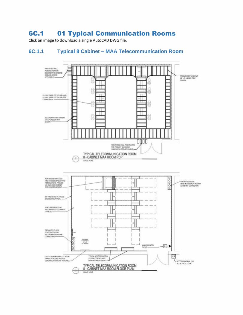
6C.1 01 Typical Communication Rooms Click an image to download a single AutoCAD DWG file.
6C.1.1 Typical 8 Cabinet – MAA Telecommunication Room
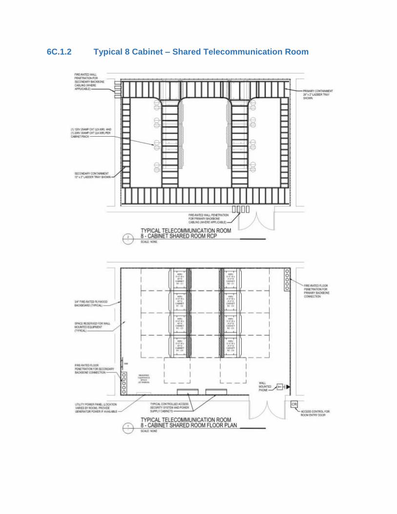
6C.1.2 Typical 8 Cabinet – Shared Telecommunication Room
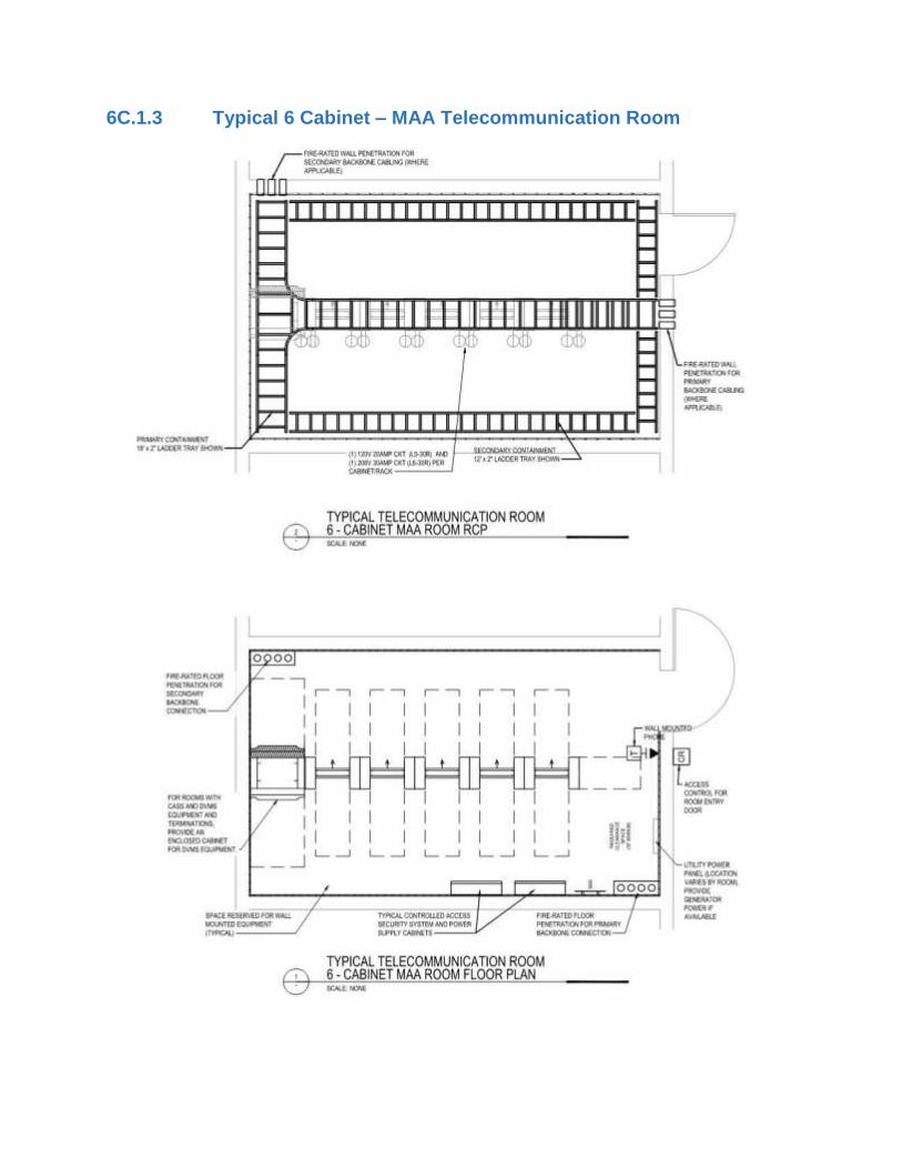
6C.1.3 Typical 6 Cabinet – MAA Telecommunication Room
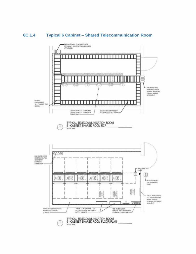
6C.1.4 Typical 6 Cabinet – Shared Telecommunication Room

6C.1.5 Typical 4 Cabinet – MAA Telecommunication Room
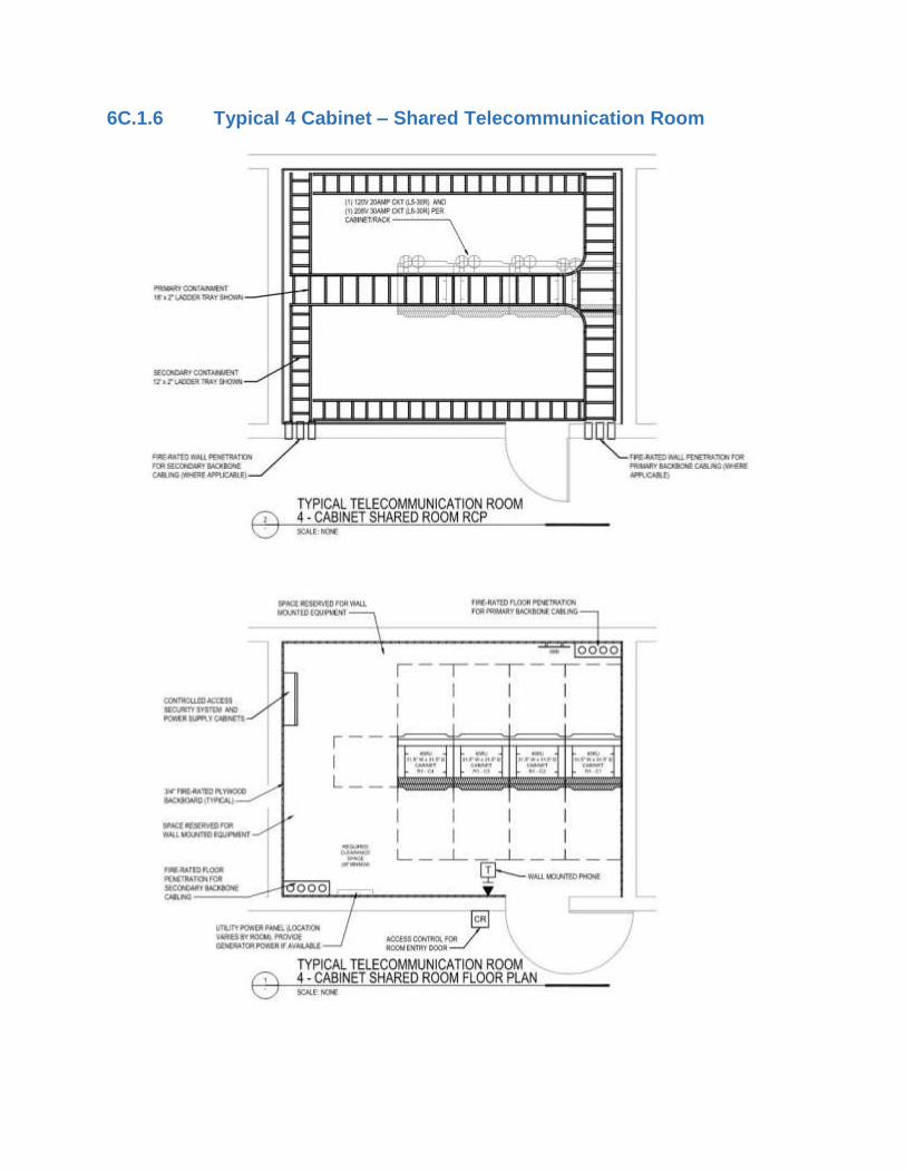
6C.1.6 Typical 4 Cabinet – Shared Telecommunication Room
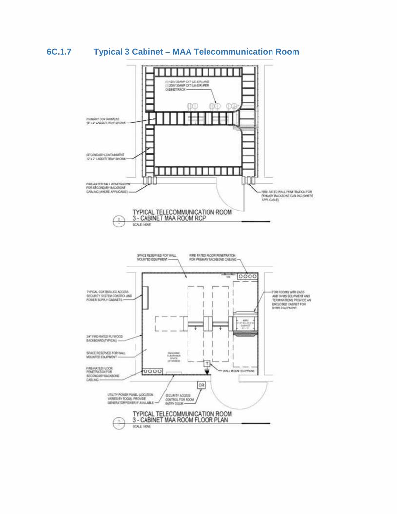
6C.1.7 Typical 3 Cabinet – MAA Telecommunication Room

6C.1.8 Typical 3 Cabinet – Shared Telecommunication Room

6C.2 Demarcation Cabinets Click an image to download a single AutoCAD DWG file.
6C.2.1 Tenant Demarcation Cabinets

6C.2.2 Concession Demarcation Cabinet

6C.3 Cable Tray Installation 6C.3.1 Cable Tray Mounting – Ceiling / Structure
6C.3.2 Dual Tray Mounting Detail
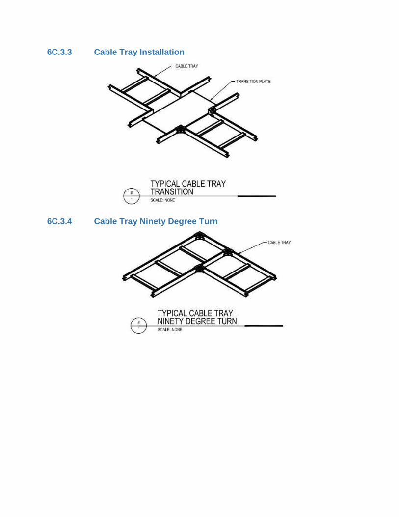
6C.3.3 Cable Tray Installation
6C.3.4 Cable Tray Ninety Degree Turn

6C.3.5 Cable Tray Conduit Sleeve Entrance

6C.3.6 Cable Tray Conduit Entrance
6C.3.7 Cable Tray Wall Sleeve

6C.3.8 Equipment Rack Cabling
6C.3.9 Cable Tray Over Rack

6C.3.10 Cable Tray Rack Elevation
6C.3.11 Equipment Rack Cable Tray – Rack Outlet
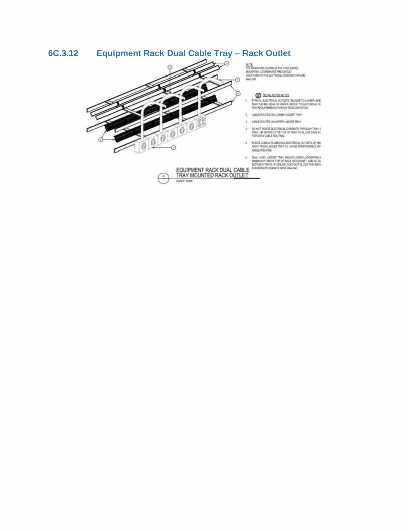
6C.3.12 Equipment Rack Dual Cable Tray – Rack Outlet

6C.4 Containment Penetrations
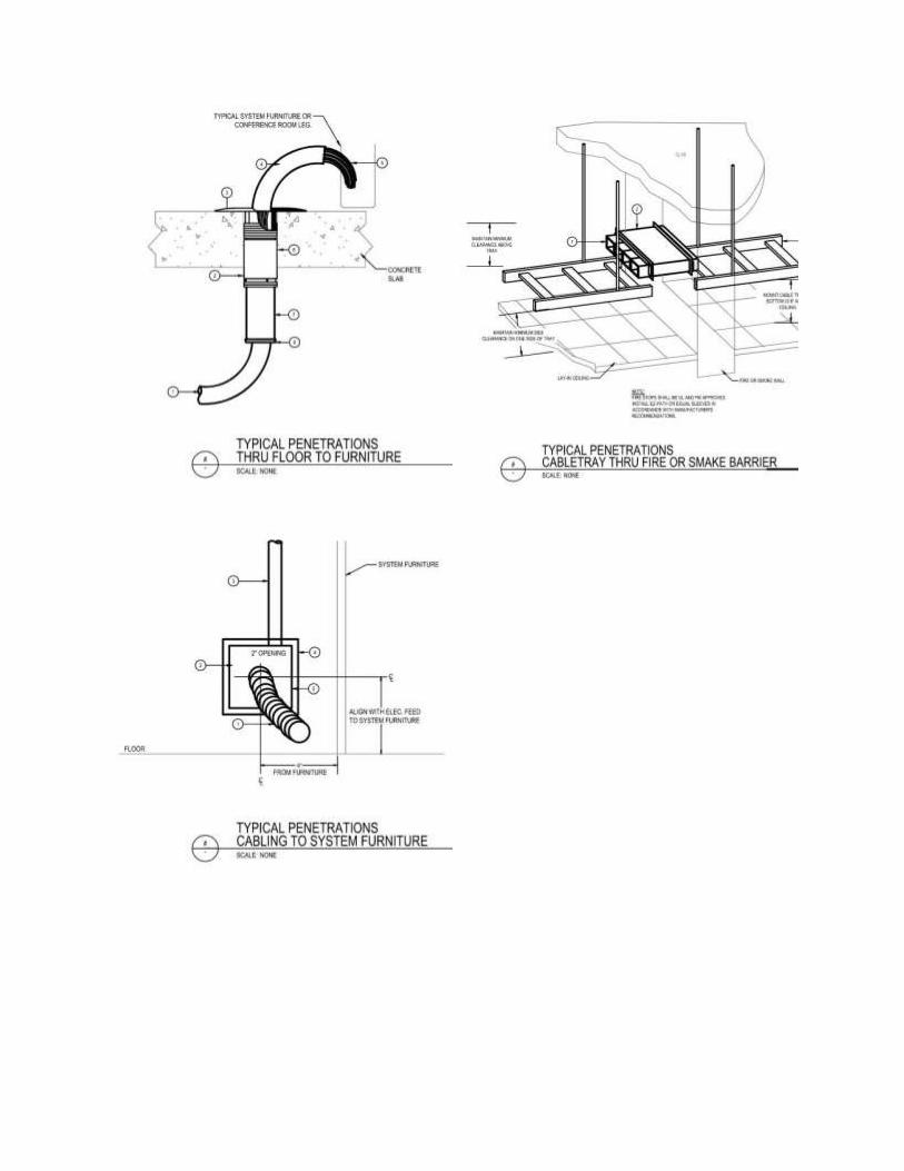
Related Documents


