Peeping ROM: A Digital Camera System for Students and Educators Sean Muller, Michael Cirelli, Jim Paris, Andrew Muth 10 August 2005 1

Welcome message from author
This document is posted to help you gain knowledge. Please leave a comment to let me know what you think about it! Share it to your friends and learn new things together.
Transcript
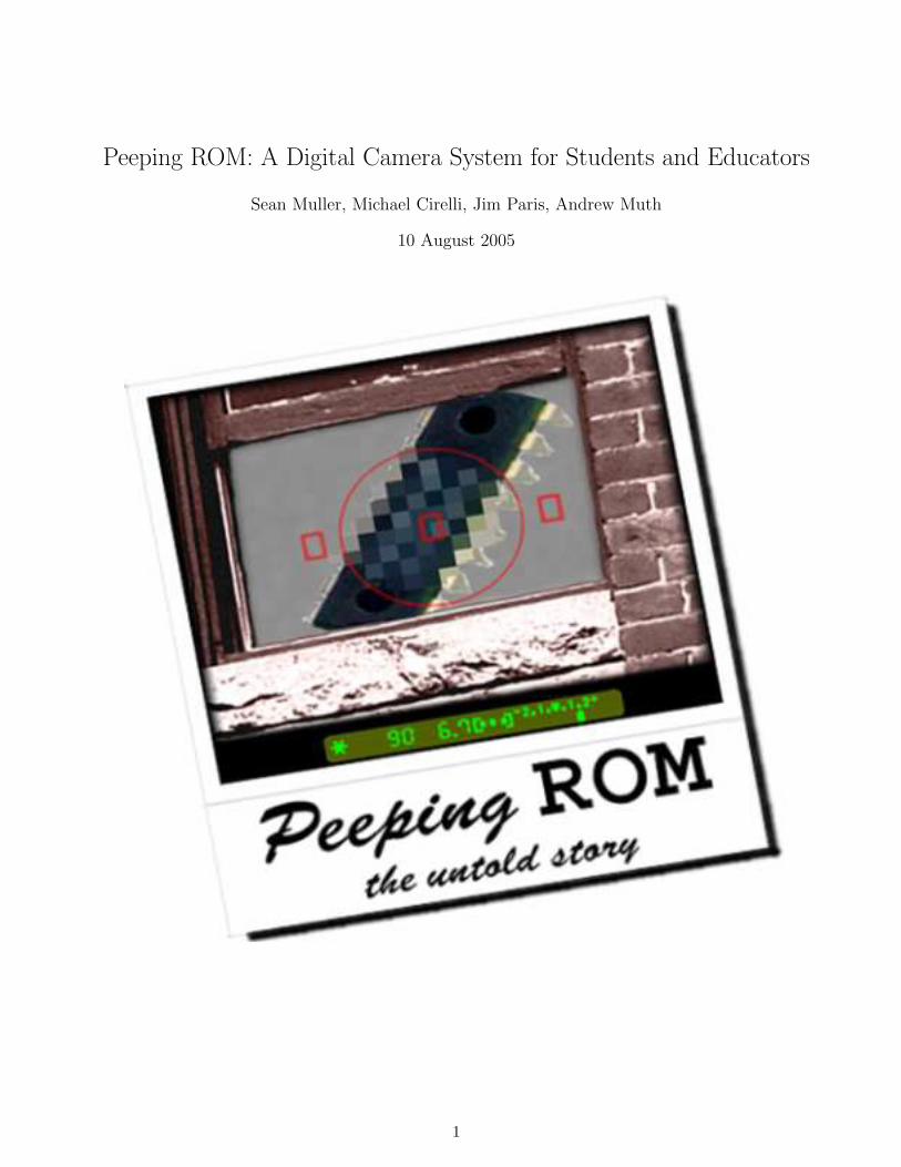
Peeping ROM: A Digital Camera System for Students and Educators
Sean Muller, Michael Cirelli, Jim Paris, Andrew Muth
10 August 2005
1
CONTENTS 2
Contents
1 Introduction 6
2 Understanding Peeping ROM 62.1 First Impressions . . . . . . . . . . . . . . . . . . . . . . . . . . . . . . . . . . . . . . . . 62.2 The Speedgraphic Model . . . . . . . . . . . . . . . . . . . . . . . . . . . . . . . . . . . . 62.3 Testing Peeping ROM . . . . . . . . . . . . . . . . . . . . . . . . . . . . . . . . . . . . . 72.4 Conclusions . . . . . . . . . . . . . . . . . . . . . . . . . . . . . . . . . . . . . . . . . . . 10
3 Using the Peeping ROM System 123.1 Testing Your Setup with test me . . . . . . . . . . . . . . . . . . . . . . . . . . . . . . . 123.2 Using picture me to Take Pictures with User Modifications . . . . . . . . . . . . . . . . 12
3.2.1 camera setup.m . . . . . . . . . . . . . . . . . . . . . . . . . . . . . . . . . . . . . 133.2.2 camera usermode.m . . . . . . . . . . . . . . . . . . . . . . . . . . . . . . . . . . 133.2.3 camera takepic.m . . . . . . . . . . . . . . . . . . . . . . . . . . . . . . . . . . . . 15
3.3 Image Generation . . . . . . . . . . . . . . . . . . . . . . . . . . . . . . . . . . . . . . . . 153.4 Understanding Peeping ROM’s Bayer Pattern Interpolation . . . . . . . . . . . . . . . . 153.5 Using Peeping ROM’s Visual Output . . . . . . . . . . . . . . . . . . . . . . . . . . . . . 183.6 Accessing Image Data Matrices . . . . . . . . . . . . . . . . . . . . . . . . . . . . . . . . 21
A Appendix A:The Hardware Components 22A.1 Schematic . . . . . . . . . . . . . . . . . . . . . . . . . . . . . . . . . . . . . . . . . . . . 23A.2 Board Layout . . . . . . . . . . . . . . . . . . . . . . . . . . . . . . . . . . . . . . . . . . 24A.3 Potential Flash Trigger Signals . . . . . . . . . . . . . . . . . . . . . . . . . . . . . . . . 24A.4 Parts List . . . . . . . . . . . . . . . . . . . . . . . . . . . . . . . . . . . . . . . . . . . . 24A.5 PIC Microcontroller Code . . . . . . . . . . . . . . . . . . . . . . . . . . . . . . . . . . . 26
A.5.1 cam.c . . . . . . . . . . . . . . . . . . . . . . . . . . . . . . . . . . . . . . . . . . 26A.5.2 sccb.c . . . . . . . . . . . . . . . . . . . . . . . . . . . . . . . . . . . . . . . . . . 28A.5.3 serial.c . . . . . . . . . . . . . . . . . . . . . . . . . . . . . . . . . . . . . . . . . . 32A.5.4 main.c . . . . . . . . . . . . . . . . . . . . . . . . . . . . . . . . . . . . . . . . . . 35A.5.5 Header Files: cam.h, sccb.h, serial.h, config.h, reg.h . . . . . . . . . . . . . . . . 40
B Appendix B:The Matlab Components 47B.1 test me.m . . . . . . . . . . . . . . . . . . . . . . . . . . . . . . . . . . . . . . . . . . . . 48B.2 picture me.m . . . . . . . . . . . . . . . . . . . . . . . . . . . . . . . . . . . . . . . . . . 50B.3 camera setup.m . . . . . . . . . . . . . . . . . . . . . . . . . . . . . . . . . . . . . . . . . 52B.4 camera usermode.m . . . . . . . . . . . . . . . . . . . . . . . . . . . . . . . . . . . . . . 54B.5 camera takepic.m . . . . . . . . . . . . . . . . . . . . . . . . . . . . . . . . . . . . . . . . 57B.6 pr bitset.m . . . . . . . . . . . . . . . . . . . . . . . . . . . . . . . . . . . . . . . . . . . 59B.7 pr check.m . . . . . . . . . . . . . . . . . . . . . . . . . . . . . . . . . . . . . . . . . . . 61B.8 pr close.m . . . . . . . . . . . . . . . . . . . . . . . . . . . . . . . . . . . . . . . . . . . . 63B.9 pr display.m . . . . . . . . . . . . . . . . . . . . . . . . . . . . . . . . . . . . . . . . . . . 65B.10 pr download.m . . . . . . . . . . . . . . . . . . . . . . . . . . . . . . . . . . . . . . . . . 67B.11 pr dlchunk.m . . . . . . . . . . . . . . . . . . . . . . . . . . . . . . . . . . . . . . . . . . 69B.12 pr dlsetup.m . . . . . . . . . . . . . . . . . . . . . . . . . . . . . . . . . . . . . . . . . . 71B.13 pr flush.m . . . . . . . . . . . . . . . . . . . . . . . . . . . . . . . . . . . . . . . . . . . . 73B.14 pr get.m . . . . . . . . . . . . . . . . . . . . . . . . . . . . . . . . . . . . . . . . . . . . . 75B.15 pr init.m . . . . . . . . . . . . . . . . . . . . . . . . . . . . . . . . . . . . . . . . . . . . . 77

CONTENTS 3
B.16 pr modeset.m . . . . . . . . . . . . . . . . . . . . . . . . . . . . . . . . . . . . . . . . . . 79B.17 pr picture.m . . . . . . . . . . . . . . . . . . . . . . . . . . . . . . . . . . . . . . . . . . . 83B.18 pr regset.m . . . . . . . . . . . . . . . . . . . . . . . . . . . . . . . . . . . . . . . . . . . 85B.19 pr regread.m . . . . . . . . . . . . . . . . . . . . . . . . . . . . . . . . . . . . . . . . . . 88B.20 pr reinit.m . . . . . . . . . . . . . . . . . . . . . . . . . . . . . . . . . . . . . . . . . . . . 90B.21 pr set.m . . . . . . . . . . . . . . . . . . . . . . . . . . . . . . . . . . . . . . . . . . . . . 92B.22 pr showpics.m . . . . . . . . . . . . . . . . . . . . . . . . . . . . . . . . . . . . . . . . . . 94B.23 bayer.m . . . . . . . . . . . . . . . . . . . . . . . . . . . . . . . . . . . . . . . . . . . . . 96B.24 histogram.m . . . . . . . . . . . . . . . . . . . . . . . . . . . . . . . . . . . . . . . . . . . 99
C Appendix C:The OmniVision OV6630 Camera Module 101C.1 OV6630 Datasheet . . . . . . . . . . . . . . . . . . . . . . . . . . . . . . . . . . . . . . . 101

CONTENTS 4
The Peeping ROM Quick Start Guide
This Quick Start guide is provided to eliminate many of the common problems experienced when settingup Peeping ROM for the first time.
• If you are setting up Peeping ROM for the first time, use this quickstart guide to get your systemconnected and tested.
• If you want detailed explanations and usage examples for each of the major Matlab functions thatrun Peeping ROM, please see section 3 on page 12.
• Experienced users looking for detailed schematics and code listings can find information in ap-pendicies A and B on pages 22 and 47, respectively.
• Finally, those looking for information on the experimental work that led to a model of PeepingROM as a vintage film camera should consult section 2 on page 6.
Hardware Setup
Please pay careful attention to the hardware setup instructions as itis possible to break the camera module by connecting it improperly.
Hardware setup involves connecting the camera and printed circuit board together with a 34-pin ribboncable. When you receive your Peeping ROM hardware these components should already be connected;however they are not permanently attached and may need to be reconnected if they become seperated.
On the circuit board a polarized hood forces the cable into its proper orientation, but on the camerathere is no similar safeguard. To attach the cable to the camera, place the header into the cablewith the text Y0 on the side with red indicator wire. It should look like this:
Header Connection Close-up
Note that the polarizing “key” of the cable connector is still visible and the two unused holes of theconnector are opposite the red indicator wire. Also check that all pins are within the connectorhousing since the camera can be connected with only some pins inserted into the cable.
If properly connected, your camera module should look like this:
Camera/Cable Connection

CONTENTS 5
If it does not look exactly like the picture, DO NOT CONNECTOR POWER to your PeepingROM board. You will break the module. Only after triple checking that this connection is correct shouldyou connect a serial cable between the PC and your hardware board. Finally, connect +8− 35V to themain circuit board to provide power. If a bright green indicator light does not come on immediately,disconnect power and check your camera connection.
Software Setup
Peeping ROM’s Matlab code is designed to run on a variety of operating systems and Matlab versions.It runs correctly under Matlab v6.5 and v7.01 on both Linux and Windows.
To operate Peeping ROM, you should open Matlab then change your current directory to the onecontaining all of the files listed on page 47. They contain all of the necessary functions to communicatewith the camera module and download an image.
Testing Your System
Testing your camera setup can be done using the Matlab function test me. Once you have completedthe hardware and software setup, make sure the green indicator light is glowing on the Peeping ROMboard, then at the Matlab prompt type test me. If everything is correct, you should see a bunch of textappear on the screen as internal functions initialize communications, check that the camera is working,and read the value of several camera parameters. Finally, after about 30 seconds of downloading, yourphotograph should appear.
Note: it is likely that the images you see after calling test me will be blurry – this is not an error fromPeeping ROM. The camera lens simply needs to be focused.
Note: the proper orientation for the camera is to have the header rows and white focusing marks atthe top. Images will appear right-side-up if the camera is held this way.
Focusing the Camera
When Peeping ROM’s camera is used with its factory-shipped lens, focusing the unit for a particularsetting is more of an art than a science. Nevertheless, every Peeping ROM camera comes with twowhite “focusing” marks (one on the lens and one on the camera housing) to make fine adjustments tothe camera’s focus easier.
Actual focusing requires taking many pictures of a scene and making adjustments as necessary. Theeasiest way to do this is with test me, though this takes a long time since each photograph takes abouta minute to fully process. Experienced users may find the best method to be taking a single test mepicture, recording the final register values from the display output, then running picture me with nodelay and all of the necessary register values preprogrammed.
1 INTRODUCTION 6
1 Introduction
For many people – students, professionals, and laypeople alike – the digital camera is a tool that allowsanyone to become a photographer overnight. Pictures are instantly viewable and can be deleted if theyare not satisfactory. The time-consuming and expensive process of getting film processed has beendone away with completely. Digital storage mediums can store thousands of photos which are easilytrasferred to PCs and the internet. However, these very attributes cause many to think of the digitalcamera as a “magical point-and-shoot box” whose only connection to the film camera is that they bothtake pictures.
We intend to dispell that myth by exposing you to the digital camera at a whole new level. Forgetthe “point-and-shoot” box – Peeping ROM takes modern camera technology back to its roots and showsthat there are indeed parallels between the inner workings of digital cameras and those of film cameras.
In this report we will accomplish three tasks: explaining the functionality of Peeping ROM’s camerain terms of an analogy with the Graphlex Speedgraphic camera, providing a full recount of our experi-mental methods that led to the Speedgraphic model of Peeping ROM, and describing in detail everythingneeded to use our hardware and software framework when performing more tests. We will also provideall code, schematics, and other data relevant to the OmniVision OV6630 module as a reference.
2 Understanding Peeping ROM
The Focal Plane Shutter & the Graphlex Speedgraphic
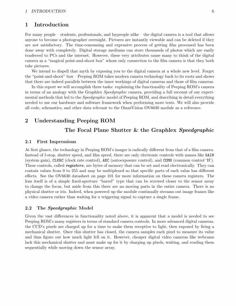
2.1 First Impressions
At first glance, the technology in Peeping ROM’s imager is radically different from that of a film camera.Instead of f-stop, shutter speed, and film speed, there are only electronic controls with names like GAIN(system gain), CLKRC (clock rate control), AEC (autoexposure control), and COMH (common control ‘H’).These controls, called registers, are bytes of memory that can be set and read electronically. They cancontain values from 0 to 255 and may be multiplexed so that specific parts of each value has differenteffects. See the OV6630 datasheet on page 101 for more information on these camera registers. Thelens itself is of a simple fixed-aperture “barrel” type that can be screwed closer to the sensor arrayto change the focus, but aside from this there are no moving parts in the entire camera. There is nophysical shutter or iris. Indeed, when powered up the module continually streams out image frames likea video camera rather than waiting for a triggering signal to capture a single frame.
2.2 The Speedgraphic Model
Given the vast differences in functionality noted above, it is apparent that a model is needed to seePeeping ROM’s many registers in terms of standard camera controls. In more advanced digital cameras,the CCD’s pixels are charged up for a time to make them receptive to light, then exposed by firing amechanical shutter. Once this shutter has closed, the camera samples each pixel to measure its valueand thus figure out how much light fell on it. However, cheaper digital video cameras like webcamslack this mechanical shutter and must make up for it by charging up pixels, waiting, and reading themsequentially while moving down the sensor array.

2 UNDERSTANDING PEEPING ROM 7
CCD Pixel Reading Pattern & Graphlex Speedgraphic Vertical Shutter
Based on this knowledge and a basic understanding of the data output from Peeping ROM, we hypoth-esized that Peeping ROM may act like the Graphlex Speedgraphic, a vintage camera that uses a focalplane slit shutter moving vertically from top to bottom. (A focal plane shutter is a shutter that exists inthe focal plane of the image rather than in the lens itself.) In these cameras the focal plane shutter hastwo adjustments: shutter tension select and slit width. The shutter tension selector changes the speedof the shutter cloth (and thus the light-emitting slit) as it moves down the film. The slit width setting,on the other hand, changes the width of the slit itself. Together these controls set the total exposuretime (in nths of a second) and allow the camera to operate in many different lighting environments.
Peeping ROM, while lacking any of the physical controls present on the Speedgraphic, has electroniccontrols that can change the pixel precharging time and overall framerate. We hypothesized thatchanging these registers may have the same effect as changing shutter speed and slit width. With thishypothesis, we then took more than 50 photographs of a single scene while making various adjustmentsto the module’s registers. These photographs would then provide information about the camera’sfunctionality, design, and potential as a useful tool for showing students the inner workings of a digitalcamera.
2.3 Testing Peeping ROM
One of the more unique examples of how photographs provide insight into the inner workings of thecamera comes from a famous picture taken by Henri Lartigue. Shown below, the image’s components“lean” in multiple directions because the camera used a vertically-travelling slit shutter to view movingobjects.

2 UNDERSTANDING PEEPING ROM 8
Lartigue’s ‘Leaning Car Race’
In the case of this photograph, the camera is panning right to follow the speeding car – this is evidentbecause the people are leaning left, caused by the camera moving an incremental amount right for eachsmall distance the shutter moved down. Meanwhile, the car tires are seen as right-pointed ovals becausethe camera is panning faster than the car is moving and thus the car is seeming to move slowly into thecenter of the frame as the exposure goes on.
Since the “leaning” behavior discussed above is intrinsic to any camera with a vertically-travellingslit shutter, we hoped to validate our hypothesized model of Peeping ROM by photographing a scenewith similar moving objects. If the photographs showed similar features we could then have a grasp onthe actual electronic shutter mechanism running Peeping ROM. With that knowledge we could thendetermine which registers, if any, would allow us to vary the slit width and speed of exposure to changethe camera’s functionality.
Experimental Setup

2 UNDERSTANDING PEEPING ROM 9
Our experimental setup was designed to hold the Peeping ROM camera module in one position somultiple pictures could be taken and compared usefully. We attached a card with text and images onit to a small gearmotor whose speed was controlled and monitored using a strobe. The backgroundwas chosen to be rich in colors and patterns while spools of red, green, and blue wire provided colorreferences.
We conducted six experimental runs to clarify our model of Peeping ROM:
1. Gathering Baseline PhotographsTesting the camera would require several baseline photographs for comparison. Also, we wantedto get the camera module focused on our scene and the ambient lighting set to acceptable levels.
2. Enabling and Disabling Automatic ModesTo make Peeping ROM useful it is necessary to disable all of the automatic modes that operatethe camera normally. However, the methodology used to change these modes is not specified inthe datasheet and many of the register settings involved are interconnected. The goal of this set ofphotos was to figure out the precise register settings needed to deactivate these automatic modesand write a program that could set them according to a user’s specification.
3. Changing Picture FrameratesA key component of our Peeping ROM model is the ability to change the apparent shutter speedof our camera. For this reason we chose to explore the effect register CLKRC (0x11) has on animage. The lower six bits of this register control the clock prescaler, with a higher value dividingthe clock by a greater number and thus increasing the expose time. Based on our hypothesis, wewould expect a faster clockspeed to act similar to a faster shutter speed, decreasing the amountof light hitting the sensor.
4. Changing Pixel Precharging TimeA second key component of our model is the ability to change the width of the imaginary “slit” inour electronic Speedgraphic. Our hypothesis suggested that the pixel precharging time would causeeffects similar to widening or shortening the slit. According to the datasheet and our observationsof register values during tests 1 and 2, register AEC (0x10) may have this effect. We expected thatlowering this value would cause the picture to darken since each pixel would be exposed to thelight source for less time between precharging and measurement.
5. Recreating Lartigue’s “Leaning Car Race”The true test of our vertical focal plane shutter model would be to recreate similar leaning andblurring features in an image from Peeping ROM. Our hypothesis suggested that a long framerate coupled with the shortest possible exposure time should yield a decent image, albeit one thatis on a time scale far slower than Lartigue’s.
Motion Apparatus (gearmotor and card)

2 UNDERSTANDING PEEPING ROM 10
6. Changing System GainControlling the overall gain of Peeping ROM is an exceedingly useful tool to use when usingunusual frame rates and exposure timings since many images will be either underexposed orshowing blooming. These photographs were designed simply to check that the system gain couldbe controlled while the automatic gain control is shut off.
These six tests provided us with enough information to validate our Peeping ROM model and actuallyspecify what registers roughly corresponded to physical adjustments on a traditonal film camera. Ourconclusions and finalized model are presented below, while details of all of our experimental runs areshown in section 3.
2.4 Conclusions
Overall, the six test series listed earlier gave positive results. automode proved useful in getting baselinephotos and experimenting with the camera given a variety of lighting environments. After some initialshortcomings we were also able to develop the list of registers that enable the automatic gain/expo-sure/white balance circuitry, which led directly to our writing of automatic mode configuration functionpr_modeset.
Once the automatic modes could be disabled without causing unintended effects on the images,we were able to proceed with our exposure control experiments. These produced the expected resultswith faster framerates and exposure timings (or, using our Speedgraphic model, shutter speeds and slitwidths) producing pictures with Lartigue’s “leaning” appearance. Changing the exposure speed to makevery long exposures also allowed for use in low-light situations, although in these cases the automaticgain needed to boost the image often produced a lot of noise in the final photo.
Peeping ROM’s “Leaning ID Card with Face”
Of course, the ability to work with the camera in detail also showed that it was at heart still just a cheapwebcam. During our experiments with the automatic gain and exposure modes we often found thatour images would be colored incorrectly or have a “washed-out” appearance due to reflective materials
2 UNDERSTANDING PEEPING ROM 11
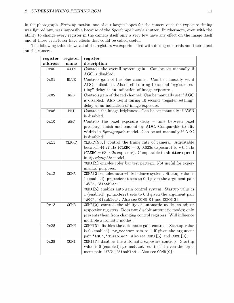
in the photograph. Freezing motion, one of our largest hopes for the camera once the exposure timingwas figured out, was impossible because of the Speedgraphic-style shutter. Furthermore, even with theability to change every register in the camera itself only a very few have any effect on the image itselfand of those even fewer have effects that could be called useful.
The following table shows all of the registers we experimented with during our trials and their effecton the camera.
register register registeraddress name description0x00 GAIN Controls the overall system gain. Can be set manually if
AGC is disabled.0x01 BLUE Controls gain of the blue channel. Can be manually set if
AGC is disabled. Also useful during 10 second “register set-tling” delay as an indication of image exposure.
0x02 RED Controls gain of the red channel. Can be manually set if AGCis disabled. Also useful during 10 second “register settling”delay as an indication of image exposure.
0x06 BRT Controls the image brightness. Can be set manually if AWBis disabled.
0x10 AEC Controls the pixel exposure delay – time between pixelprecharge finish and readout by ADC. Comparable to slitwidth in Speedgraphic model. Can be set manually if AECis disabled.
0x11 CLKRC CLKRC[5:0] control the frame rate of camera. Adjustablebetween 44.27 Hz (CLKRC = 0, 0.023s exposure) to ∼0.5 Hz(CLKRC = 63, ∼2s exposure). Comparable to shutter speedin Speedgraphic model.COMA[1] enables color bar test pattern. Not useful for exper-imental purposes.
0x12 COMA COMA[2] enables auto white balance system. Startup value is1 (enabled); pr_modeset sets to 0 if given the argument pair‘AWB’,‘disabled’.COMA[5] enables auto gain control system. Startup value is1 (enabled); pr_modeset sets to 0 if given the argument pair‘AGC’,‘disabled’. Also see COMB[0] and COMH[3].
0x13 COMB COMB[0] controls the ability of automatic modes to adjustrespective registers. Does not disable automatic modes; onlyprevents them from changing control registers. Will influencemultiple automatic modes.
0x28 COMH COMH[3] disables the automatic gain controls. Startup valueis 0 (enabled); pr_modeset sets to 1 if given the argumentpair ‘AGC’,‘disabled’. Also see COMA[5] and COMB[0].
0x29 COMI COMI[7] disables the automatic exposure controls. Startupvalue is 0 (enabled); pr_modeset sets to 1 if given the argu-ment pair ‘AEC’,‘disabled’. Also see COMB[0].

3 USING THE PEEPING ROM SYSTEM 12
3 Using the Peeping ROM System
Peeping ROM is designed to make experimenting with the many possibilities of this digital camera sys-tem as simple as possible. Every register can be altered using our Matlab scripts, though preprogrammedhardware interlocks are in place to ensure that one cannot tamper with system critical settings. Wehave also provided several wrapper functions that simplify testing your camera setup, taking a picture,viewing all of the image data, and inputting user changes.
Note: We recommend using at least Matlab v7.0 to run Peeping ROM. While all of the controlfunctions should work with older versions of Matlab, they may take substantially longer (∼300%) todownload an image.
3.1 Testing Your Setup with test me
test_me() is a function that allows the user to test his or her camera system. It places the camerainto all of its automatic modes, waits the proper amount of time, captures an image, and displays it.Though the user cannot specify any register changes to alter the camera settings when using test_me,it is useful for capturing baseline photos and viewing what “acceptable” register values are, given aparticular lighting environment.
To use this mode, simply ensure that your camera is connected and powered up then call test_me atthe matlab prompt. After initializing the camera, the program will wait several seconds before capturinga photo and downloading it to the screen. During this delay the program will return data on 7 registers:BLUE, RED, CTR, BRT, SHP, AEC, and GAIN.
As a reference, the code listing for test_me.m is in article 1 in appendix B.
automode photograph
3.2 Using picture me to Take Pictures with User Modifications
picture_me() is a wrapper function that calls a number of other matlab functions to take a picture afterapplying user-specifed changes to camera registers. More specifically, picture_me allocates variables,

3 USING THE PEEPING ROM SYSTEM 13
calls the image capture functions, applies user changes, displays the resulting data, and returns the rawimage data in matrix format.
To use this mode, ensure that your camera is connected and powered up then call picture_me() atthe Matlab prompt. The program will then call the camera_setup, camera_usermode, camera_takepic,and image generation functions (bayer.m and pr_showpics.m) described in sections 3.2.1 to 3.2.3 totake a photo. All user-specified changes are made in camera_usermode.
Note: In general, the user should not need to edit anything in picture_me itself; however if a specificserial port is desired it can be entered as an argument to camera_setup, i.e. camera_setup(‘/dev/ttyS2’)or camera_setup(‘COM3’). To alter registers, use the pr_regset function in camera_usermode.m.
As a reference, the code listing for picture_me.m is in article 2 in appendix B. The following sections3.2.1 through 3.2.3 will describe in detail exactly how the picture_me code works, how to interact withit or add user modifications, and how to interpret its graphical output.
3.2.1 camera setup.m
The purpose of camera_setup() is to properly open a serial port and reinitialize the camera system.The program allows for the user to specify a serial port to use; alternatively the program will default tothe standard system serial port. For more information on this, see pr_init.m in article 13 of appendix Bor “Using picture me to Take Pictures with User Modifications” in section 3.2.
As a reference, the code listing for camera_setup.m is in article 3 of appendix B.
3.2.2 camera usermode.m
camera_usermode() is the main function for camera-user interaction and modification. It allows fordisabling automatic modes, performing any register changes desired by the user, and displaying a verboseoutput during the 10-second waiting period before the snapshot occurs.Interacting with the camera registers can be done in 4 ways:
1. Enabling or disabling automatic modes with pr_modeset. pr_modeset takes six (optionallyseven) strings as function arguments, with valid options being ‘AEC’ (autoexposure), ‘AWB’ (autowhite balance), ‘AGC’ (auto gain control), ‘enabled’, and ‘disabled’. The function expectsarguments in pairs of the form <mode>,<state>, though the pairs themselves can occur in anyorder. As a final argument, pr_modeset can take either ‘verbose’ or ‘quiet’, though it defaultsto quiet mode if no argument is given.
For example, to turn off the Auto White Balance and see all of the register changes, you wouldchange the pr modeset(...) command (line 10 in camera_usermode.m) to read:
pr_modeset(’AEC’,’enabled’,’AGC’,’enabled’,’AWB’,’disabled’,’verbose’);
On the other hand, if you wanted to turn all of the automatic modes off and not see any of theregister changes on screen, you would enter:
pr_modeset(’AEC’,’disabled’,’AWB’,’disabled’,’AGC’,’disabled’,’quiet’); orpr_modeset(’AGC’,’disabled’,’AEC’,’disabled’,’AWB’,’disabled’);
For more information and code listings of pr_modeset, please see article 8 in appendix B.
2. Changing register settings with pr_regset. pr_regset takes a list of two (optionally three)arguments to set any of Peeping ROM’s 92 registers to a particular value. The function calls shoulduse the following formatting: <register number>,<new value>, (<‘verbose’/‘quiet’>).These inputs can accept either hexadecimal values formatted as character strings (i.e., ‘D3’ or

3 USING THE PEEPING ROM SYSTEM 14
‘47’) or decimal values from 0 to 255. If desired, ‘verbose’ or ‘quiet’ can be passed to see theregister being changed, its original value, the value it is being given, and its value after being readagain. This feature can be useful as some registers have masks in hardware or strange behaviorthat prevents them from taking a user-specified value. Like pr_modeset, this function defaults toquiet mode if not told otherwise.
To use this function to set register 0x1B to 128 with the debug output, you would enter:
pr_regset(’1B’,128,’verbose’);
If you wanted to set register 37 to value 0xFD with no screen output, you would enter:
pr_regset(37,’FD’);
For more information and code listings of pr_regset, please see article 16 in appendix B.
3. Changing specific bits in a register with pr_bitset. Many of the registers on Peeping ROM’scamera are multiplexed such that specific bits have independent functions. For this reason it maybe necessary to toggle the state of a particular bit without changing the value of its neighbors.While it is possible to accomplish this with logical operations and register-wide reads and writes,we have provided the function pr_bitset to simplify this problem.
pr_bitset expects three (optionally four) arguments of the form <register number>,<bitnumber>,<value>,(<‘verbose’/‘quiet’>). The register input can be either a character stringcontaining a hexadecimal value or a plain decimal input from 0 to 255. The bit argument iszero-centered so it ranges from bit 0 (the LSB) to bit 7 (the MSB). The value argument shouldbe either 0 or 1. Finally, this function can accept a fourth ‘verbose’ or ‘quiet’ argument anddefaults to quiet mode if not specified.
For example, to set bit 4 of register 0x2D to 1 with a verbose output, you would enter:
pr_bitset(’2D’,4,1,’verbose’);
For more information and code listings of pr_bitset, please see article 6 in appendix B.
4. Reading register values with pr_regread. There may be cases when it is desirable to knowthe value of a register at startup without changing its value. To do this, enter the following lineof code (with <reg#> set to the value of the register address):
pr regread(reg# );
This will print the value of the register reg# in the Matlab terminal. If it is given a characterstring (i.e. ‘F3’) the function will interpret this as a hexadecimal value; otherwise it will expecta decimal value.
Note: This function uses sprintf, an intrinsic Matlab function. For more information on itsusage please see Matlab’s help files. For more information on pr_get, please see article 14 ofappendix B.
To perform the changes shown above, camera_usermode.m must be edited manually before runningpicture_me. Changing pr_modeset is done by directly altering its existing function call on line 10.Adding register or bitset operations should be done after line 18, in place of the comment “%% insert changes here.”
Note: Changing the output display during the register “settling” period. Despite thefast processor clock on Peeping ROM’s camera, the automatic gain/white balance/exposure circuitry

3 USING THE PEEPING ROM SYSTEM 15
still takes time to arrive at an optimal value. During our experimentation we found that it took between5 and 10 seconds for the camera to reach its optimal values. We also found that it was useful to seethe value of several registers on the camera (typically those associated with the automatic modes andexposure timings) over the course of this delay period since they provide insight to the camera’s lightenvironment and image output.
If desired, this output can be enabled by changing the camera_usermode() call in picture_me.mto have the argument ‘verbose’. This will cause the display to show the time remaining before imagecaputure, as well as the state of registers BLUE, RED, CTR, BRT, SHP, AEC, and GAIN, once per second.This mode is turned off by default and must be manually enabled in picture_me.m.
Note: It is also possible to remove this 10 second delay completely by sending camera_usermodethe argument ‘no-delay’. This can speed up the total time it takes to get a picture (it removes 10seconds of delay), but only use this argument if you have disabled all of the automatic modes and settheir registers to values that will produce a desirable image. Otherwise, you may not see a useful image.
As a reference, the code listing for camera_usermode.m is in article 4 of appendix B.
3.2.3 camera takepic.m
camera_takepic is a wrapper function that tells the camera board to actually perform an image capture,download the image, close the serial port, and return a 349 × 288 matrix containing the downloadedimage data. Each byte will be a value from 0 to 255. While the data downloads the percentage completewill display every 5 seconds, and at the end of the download the total time in seconds is shown.
As a reference, the code listing for camera_takepic.m is in article 5 of appendix B.
3.3 Image Generation
Image generation in Peeping ROM takes two distinct steps – interpolation of raw data, then the actualon-screen figure generation. Interpolation is done with the bayer pattern decoder function bayer.m,which processes the raw data and generates four output matrices corresponding to red, green, blue,and full-color images. For more information on the Bayer pattern and Peeping ROM’s interpolationtechnique, see section 3.3.
Generating the actual picture output is handled by another function, pr_showpics, which takes theoutput of the bayer interpolation function and displays all of the data. It will display the raw BWimage before any interpolation, the red/green/blue pixel data before interpolation, the red/green/bluechannel information post-interpolation, a composite brightness histogram, and the final full-color imageitself. Each of these images will appear in their own unique frame and will refresh in those identicalframes if another image is taken. For more information on interpreting these visual outputs, please seesection 3.5.
As a reference, the code listing for pr_showpics.m is in article 22 of appendix B.
3.4 Understanding Peeping ROM’s Bayer Pattern Interpolation
A key difference between the operation of a typical film camera and the Peeping ROM image sensor isthat the raw image captured by the camera does not contain the full color information at every pixel.Rather, each pixel is just a small grayscale light intensity meter producing a value from 0 (pure dark)to 255 (pure light). Color sensitivity is achieved using microscopic filters placed over every pixel, thusmaking each pixel sensitive to only one color. For Peeping ROM, the sensor elements form a 349 × 288grid with either a red, green, or blue filter covering each pixel in a special arrangement called the Bayer

3 USING THE PEEPING ROM SYSTEM 16
Pattern. As shown in the following picture, this pattern is an alternating grid with twice as many greenpoints as red or blue points – this accounts for the human eye’s hightened sensitivity to green light.
Bayer Pattern
Given the Bayer color filter, an interpolation technique is needed to convert the single-channel inputinto a full-color, three-channel input. Peeping ROM uses a simple averaging interpolation algorithmsince the number of input pixels is the desired number of output pixels and image quality is not of hugeimportance. In bayer.m, the original data input is converted into three matrices – red, green, blue –with each having a value at a particular pixel only if that pixel was covered with the respective matrice’scolor. All other pixels are set to 0, which leaves them black.
Step 1: Select Only One Color
Next, the closest neighboring pixels are averaged to provide an interpolated value for each pixel thatexists in the full image but was covered with a different colored filter.
3 USING THE PEEPING ROM SYSTEM 17
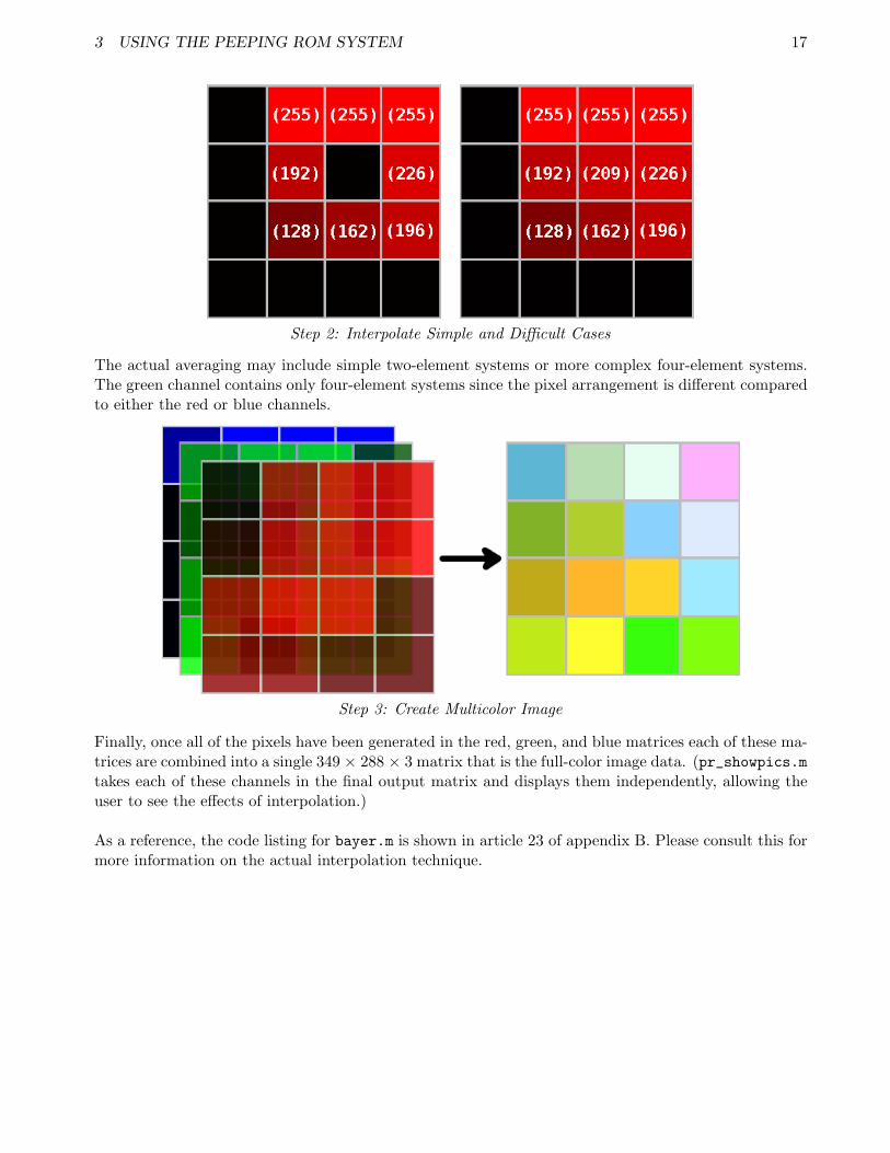
Step 2: Interpolate Simple and Difficult Cases
The actual averaging may include simple two-element systems or more complex four-element systems.The green channel contains only four-element systems since the pixel arrangement is different comparedto either the red or blue channels.
Step 3: Create Multicolor Image
Finally, once all of the pixels have been generated in the red, green, and blue matrices each of these ma-trices are combined into a single 349 × 288 × 3 matrix that is the full-color image data. (pr_showpics.mtakes each of these channels in the final output matrix and displays them independently, allowing theuser to see the effects of interpolation.)
As a reference, the code listing for bayer.m is shown in article 23 of appendix B. Please consult this formore information on the actual interpolation technique.

3 USING THE PEEPING ROM SYSTEM 18
3.5 Using Peeping ROM’s Visual Output
Since Peeping ROM is designed to be an educational tool, it provides visual output at every stage of theimage capture process. The following table describes each of the nine output windows that are opened(via pr_showpics) after an image is downloaded. The names in brackets in the third column are theactual variable names used in picture_me and automode to store the image data. For information onaccessing these variables after program execution and picture capture, please see section 3.6.
Pre-Interpolation Pixels, Post-Interpolation Pixels, Raw Data PixelsBlue Channel Blue Channel <raw pic>
Pre-Interpolation Pixels, Post-Interpolation Pixels, Final Color ImageGreen Channel Green Channel <color pic>
Pre-Interpolation Pixels, Post-Interpolation Pixels, Brightness HistogramRed Channel Red Channel <hist>
Peeping ROM visual output

3 USING THE PEEPING ROM SYSTEM 19
Pre-Interpolation Images
pr_showpics, the default image display function for Peeping ROM, presents the user with four pre-interpolation images – the raw pixel image and each of the three color channels. One should note thatall of these images show particular patterns and graininess that is caused by the presence of the Bayercolor filters. Also noteworthy is the fact that all of the single-color channels are significantly darkerthan their post-interpolation counterparts. This is caused by the fact that in any arbitrary 2 × 2 groupof pixels, one quarter is blue, a second quarter red, and half green. This can be seen visually by usingzooming in on the pre-interpolation images until the individual pixel patterns are visible. At this level,the Bayer patterning will be plainly evident – only the pixels of a particular channel’s color will bevisible. All other pixels will be black since there is no data for the selected channel available.
Post-Interpolation Images
The four post-interpolation pictures are interesting because they show the effects of Peeping ROM’ssimple interpolation algorithm. The single color figures are interesting because they no longer show anypixelation caused by a lack of image data. However, blurring and image artifacts can appear as a resultof the basic interpolation scheme.
Brightness Histogram
On many modern digital cameras, a brightness histogram can be displayed to show information aboutthe estimated exposure level of a photograph. Our technique, while not being identical to those intrue cameras, shows the distribution of pixel intensity values in the final full-color image. Since thisimage is represented in Matlab as a matrix of 349 × 288 pixels by 3 channels, we perform the followingconversion to generate a matrix that has the effective brightness of each pixel. This algorithm takesinto account the human eye’s differing sensitivity to red, green, and blue wavelengths.
Pbrightness = (.299 · Pred) + (.587 · Pgreen) + (.114 · Pblue)
This algorithm is run on each pixel in the final image, giving a single 349 × 288 matrix containing thebrightness of each pixel. These values, after being rounded to the nearest integer, contain values from0 (pure black) to 255 (pure white). The histogram function then compares each of these values withevery number from 0 to 255 and records how many of each value it finds. This data is then normalized(divided by the total number of pixels in the image, 100,512) and diplayed as a bar graph.
Why do this? As noted earlier, a brightness histogram provides useful information on the overallexposure of the photograph. If the peak of the histogram is located close to the left, it indicates thatthere are many more dark pixels than light ones and the image is probably underexposed. The converseis also true, with a peak around 255 meaning that the image is blooming. A secondary benefit of thehistogram is that it gives insight into the values contained in the picture data matrices without havingto actually go through them. While histogram.m itself is a specialized function made specifically forthe 3 channel color image matrix, the brightness sorting routine can be adapted in other user-writtenfunctions to look at pixel value frequencies in other matrixes.
For more information and code listings of histogram.m, please see article 24 of appendix B.

3 USING THE PEEPING ROM SYSTEM 20
Histogram for Underexposed Image

3 USING THE PEEPING ROM SYSTEM 21
3.6 Accessing Image Data Matrices
Peeping ROM is designed to display a number of images and a composite brightness histogram. However,there may be times when a more in-depth analysis of image data is desired. For this reason PeepingROM makes three of its final data matrices accessible to the user: raw_pic, color_pic, and hist.These matrices are provided in that order as output values from the picture_me function. The usercan make these available by calling picture_me with the following syntax:
[variable 1 variable 2 variable 3 ] = picture me;
variable 1 will contain raw_pic, a 349 × 288 × 1 matrix containing the actual data (0-255) read offthe camera at each pixel location. variable 2 will contain color_pic, the post-interpolation 349 ×288 × 3 matrix containing the value for each pixel (0-255) in the final image. Finally, variable 3 willcontain hist, a 256 × 1 matrix containing the raw brightness histogram data. Its values will be floatingpoint numbers between 0 and 1. Alternatively, the user can ignore the output from picture_me byleaving out any of the material before the equals sign in the command listing shown above.
A APPENDIX A: THE HARDWARE COMPONENTS 22
A Appendix A:The Hardware Components
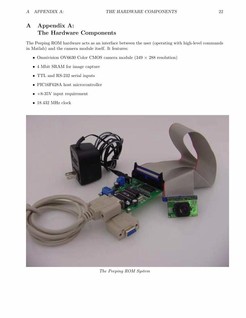
The Peeping ROM hardware acts as an interface between the user (operating with high-level commandsin Matlab) and the camera module itself. It features:
• Omnivision OV6630 Color CMOS camera module (349 × 288 resolution)
• 4 Mbit SRAM for image capture
• TTL and RS-232 serial inputs
• PIC16F628A host microcontroller
• +8-35V input requirement
• 18.432 MHz clock
The Peeping ROM System

A APPENDIX A: THE HARDWARE COMPONENTS 23
A.1 Schematic
Peeping ROM schematic

A APPENDIX A: THE HARDWARE COMPONENTS 24
A.2 Board Layout
Peeping ROM board layout
A.3 Potential Flash Trigger Signals
Adding a flash trigger may be done using pin 2 (RA3) on the PIC controller board. This TTL signal isdriven by the PIC to enable writes into the onboard RAM of Peeping ROM. However, its usability asa flash trigger may be limited by the long exposure times of the camera module since Peeping ROM isnot capable of generating a full frame of data faster than 45 frames/second.
A.4 Parts List
Every component necessary for building the Peeping ROM hardware component, with part numbers atDigikey.

A APPENDIX A: THE HARDWARE COMPONENTS 25
part number Digikey number Part DescriptionIC1 296-8340-5-ND 74HC590 counterIC2 296-8340-5-ND 74HC590 counterIC3 296-8340-5-ND 74HC590 counterIC4 296-4360-1-ND 74AC10 3-input NANDIC5 296-12791-5-ND 74HC165 shift registerIC6 MAX233CPP-ND MAX233 RS232 transceiver
IC6-S AE7220-ND 20 pin socketIC7 428-1075-ND CY62148 4Mbit SRAMIC8 LM7805CT-ND 5V positive regulatorU1 PIC16F628A-I/P-ND PIC16F628A
U1-S AE7218-ND 18 pin socketQ1 X179-ND 18.432 MHz crystalX1 A2100-ND Female DB9 socketX2 ED1601-ND Terminal blockX3 ED1602-ND Terminal blockX4 CP-102A-ND DC power jack 2.1mm
CABLE C3DDG-3418G-ND IDC 34-pin, 18 inCAM AHL34G-ND 34-pin shrouded header
R1 311-13KECT-ND 13kΩ resistor 1206R2 311-13KECT-ND 13kΩ resistor 1206R3 311-1.5KECT-ND 1.5kΩ resistor 1206R4 311-300ECT-ND 300Ω resistor 1206R5 311-120ECT-ND 120Ω resistor 1206D1 1N4001GICT-ND 1N4001 diode
LED 67-1357-1-ND Green LED 1206C1 BC1300CT-ND .1µF ceramic cap 0805C2 BC1300CT-ND .1µF ceramic cap 0805C3 BC1300CT-ND .1µF ceramic cap 0805C4 BC1300CT-ND .1µF ceramic cap 0805C5 BC1300CT-ND .1µF ceramic cap 0805C7 P836-ND 47µF electrolytic capC8 P836-ND 47µF electrolytic capC9 BC1260CT-ND 22pF ceramic cap 0805C10 BC1260CT-ND 22pF ceramic cap 0805
A APPENDIX A: THE HARDWARE COMPONENTS 26
A.5 PIC Microcontroller Code
The Peeping ROM system uses a standard PIC16F628A running on an external 18.432 MHz crystal toact as the interface between the camera module, memory, and computer. All of the Matlab functionsdiscussed in section 4 and appendix B send data to this chip to be interpreted and turned into theproper SCCB protocol that the camera then uses.
As a side note, there should be no need for the user to change any of this code. It is provided solelyas a reference.
A.5.1 cam.c
cam.c provides several of the necessary support routines that allow for register access over the SCCBbus, initialize the camera to safe starting values, and reset the device. It uses cam.h, sccb.h, and reg.h.
#ifdef PIC#include <pic.h>#endif#include ”sccb.h”
5#include ”cam.h”
#include ”reg.h”
uint8 cam get(uint8 reg)10
return sccb get(0xC0, reg);
void cam set(uint8 reg, uint8 val)15
sccb put(0xC0, reg, val);
void cam set safe(uint8 reg, uint8 val)20
/∗ Like cam set, but makes sure particular values are setthe correct way to avoid hardware damage.Returns actual value written, or −1 if it was disallowed. ∗/
unsigned char i;25
if(reg > 0x5c) return;
for(i=0; disallowed 6630[i] < reg; i++)continue;
30if(disallowed 6630[i] == reg)return;
for(i=0; safe 6630[i].reg < reg; i++)continue;
35if(safe 6630[i].reg == reg) val &= safe 6630[i].mask;val |= safe 6630[i].set;
40cam set(reg, val);
A APPENDIX A: THE HARDWARE COMPONENTS 27
/∗ Detect, reset, and initialize the chip. Only returns on success ∗/void cam reset(void)
45uint8 i, j;
sccb init();
50for(;;) /∗ Reset chip ∗/cam set(COMA, 0x80);
/∗ Delay 1 second. Camera needs time to settle.. ∗/55for(i=0; i<100; i++)
for(j=0; j<100; j++)sccb delay(100);
/∗ Check ID ∗/60if(cam get(MIDH) == 0x7F &&
cam get(MIDL) == 0xA2)break;
for(i=0; init 6630[i].reg != 0xff; i++)
65cam set(init 6630[i].reg, init 6630[i].val);
/∗ Set the Y/UV tristate bit, and return nonzero if that bit is now set ∗/uint8 cam tristate(uint8 hiz)
70uint8 v;
v = cam get(COMB);if(hiz)
75v |= 0x04;else
v &=˜0x04;cam set(COMB, v);return cam get(COMB) & 0x04;
80

A APPENDIX A: THE HARDWARE COMPONENTS 28
A.5.2 sccb.c
sccb.c is the actual SCCB (Serial Camera Control Bus) implementation on the PIC. It contains 7functions that initialize the bus, set start/stop conditions, and allow bidirectional communication be-tween the camera and the PIC. It uses sccb.h and serial.h. For more information on the SCCB busprotocol please see article 2 of appendix C.
/∗ Talk to the camera’s SCCB bus, which is basically a subset of I2C. ∗/
#ifdef PIC#include <pic.h>
5#endif#include ”sccb.h”#include ”serial.h”
/∗ Timings, in us ∗/10#define T SCL HIGH 10 /∗ min clock high period ∗/
#define T SCL LOW 10 /∗ min clock low period ∗/#define T START SETUP 25 /∗ setup before start ∗/
#if 015#define T BUS FREE 5∗5 /∗ bus free between transfers ∗/
#define T START HOLD 5∗4 /∗ hold time for start condition ∗/#define T STOP SETUP 5∗4 /∗ setup before stop ∗/#define T SCL LOW 5∗5 /∗ min clock low period ∗/#define T SCL HIGH 5∗4 /∗ min clock high period ∗/
20#define T SCL TO DATA 5∗4 /∗ SCL low to data valid, for reads ∗/#define T DATA SETUP 5∗1 /∗ data setup ∗/#endif
/∗25∗ Internal low−level functions
∗/
/∗ Send start condition ∗/void sccb start(void)
30/∗ Ensure that we’re floating clock high, data high ∗/SCL = 0;SCL TRI = 1;SDA = 1;
35SDA TRI = 0;sccb delay(T START SETUP);
/∗ Float clock high, then pull data low ∗/SCL TRI = 1;
40sccb delay(T SCL HIGH/2);SDA = 0; /∗ high −> low with SCL = 1 ∗/sccb delay(T SCL HIGH/2);
45/∗ Send stop condition ∗/void sccb stop(void)
/∗ Ensure that we’re pulling data low, clock low ∗/SCL = 0;
50SCL TRI = 0;

A APPENDIX A: THE HARDWARE COMPONENTS 29
sccb delay(T SCL LOW/2);SDA = 0;SDA TRI = 0;sccb delay(T SCL LOW/2);
55
/∗ Float clock high, then pull data high ∗/SCL TRI = 1;sccb delay(T SCL HIGH/2);SDA = 1; /∗ low −> high with SCL = 1 ∗/
60sccb delay(T SCL HIGH/2);
/∗ Float data ∗/SDA TRI = 1;
65
/∗ Send raw byte to slave. Returns acknowledgement bit ∗/uint8 sccb send(uint8 data)
uint8 i;70
for(i=8; i>0; i−−) /∗ Drive clock low, then set data ∗/SCL = 0;SCL TRI = 0;
75
sccb delay(T SCL LOW/2);
SDA = (data & 0x80) ? 1 : 0;SDA TRI = 0;
80data <<= 1;
sccb delay(T SCL LOW/2);
/∗ Float clock high ∗/85SCL TRI = 1;
/∗ Wait for the slave to let it go ∗/while(SCL == 0) continue;
90/∗ Now make sure it stays high for a bit ∗/sccb delay(T SCL HIGH);
/∗ Now read acknowledgement back. Set clock low and tristate data ∗/95SCL = 0;
SCL TRI = 0;SDA TRI = 1;
sccb delay(T SCL LOW);100
/∗ Float clock high, wait for slave to let it go ∗/SCL TRI = 1;while(SCL == 0) continue;
105/∗ Read the bit and return it ∗/sccb delay(T SCL HIGH/2);i = SDA;
A APPENDIX A: THE HARDWARE COMPONENTS 30
sccb delay(T SCL HIGH/2);return i;
110
/∗ Read raw byte from slave. Replies with acknowledgement bit. ∗/uint8 sccb recv(uint8 ack)
115uint8 i, data = 0;
for(i=8; i>0; i−−) /∗ Drive clock low, then release data ∗/SCL = 0;
120SCL TRI = 0;SDA TRI = 1;sccb delay(T SCL LOW);
/∗ Float clock high, wait for slave ∗/125SCL TRI = 1;
while(SCL == 0) continue;
/∗ Wait and read the byte ∗/sccb delay(T SCL HIGH);
130data <<= 1;data |= SDA;
/∗ Send acknowledgement. Drive clock low and set data. ∗/135SCL = 0;
SCL TRI = 0;sccb delay(T SCL LOW/2);SDA = (ack & 1);SDA TRI = 0;
140sccb delay(T SCL LOW/2);
/∗ Float clock high, then we’re done ∗/SCL TRI = 1;sccb delay(T SCL HIGH);
145
return data;
/∗150∗ Public high−level interface
∗/
/∗ Initialize SCCB bus ∗/void sccb init(void)
155SCL TRI = 1;SDA TRI = 1;
160/∗ Put a byte to register ”subaddress” in chip ”address” with data ”data” ∗//∗ Acknowledgement bits are ignored. ∗/void sccb put(uint8 address, uint8 subaddress, uint8 data)
sccb start();
A APPENDIX A: THE HARDWARE COMPONENTS 31
165sccb send(address | 0x00);sccb send(subaddress);sccb send(data);sccb stop();
170
/∗ Get a byte from register ”subaddress” in chip ”address” ∗/uint8 sccb get(uint8 address, uint8 subaddress)
uint8 data = 0;175
sccb start();sccb send(address | 0x00);sccb send(subaddress);sccb stop();
180sccb start();sccb send(address | 0x01);data = sccb recv(SCCB NAK);sccb stop();return data;
185
A APPENDIX A: THE HARDWARE COMPONENTS 32
A.5.3 serial.c
serial.c provides support for the PIC’s onboard UART. This allows the PIC to communicate withMatlab on the host PC through a serial connection. It uses serial.h.
#ifdef PIC#include <pic.h>#endif#include ”serial.h”
5
/∗ Initialize serial port ∗/void serial init(void)
int i;10TRISB1 = 1;
TRISB2 = 0;
BRGH = 1;#define BRG (((FOSC + (8 ∗ BAUDRATE − 1)) /(16 ∗ BAUDRATE)) − 1)
15#if (BRG < 1) || (BRG > 255)#error Cannot achieve baudrate#endif#define ACT BR (FOSC / (16 ∗ (BRG + 1)))#if ((ACT BR ∗ 100 / BAUDRATE) > 105) || ((ACT BR ∗ 100 / BAUDRATE) < 94)
20#error Actual baudrate is too far from requested baudrate. Ratio is#error FOSC/(16∗floor((FOSC+(8∗BAUDRATE−1))/(16∗BAUDRATE)))/BAUDRATE#endif
SPBRG = BRG;25SYNC = 0;
SPEN = 1;CREN = 1;SREN = 0;TXIE = 0;
30RCIE = 0;TX9 = 0;RX9 = 0;TXEN = 1;for(i=0; i<100; i++)
35continue;
/∗ Send byte, blocking ∗/void serial put(unsigned char x)
40while(!TXIF)
;TXREG = x;
45
/∗ Send string, blocking ∗/void serial put string(const uint8 ∗s)
int i;50for(i=0; s[i]; i++)
serial put(s[i]);
A APPENDIX A: THE HARDWARE COMPONENTS 33
/∗ Send CRLF ∗/55void serial crlf(void)
serial put 2(’\r’,’\n’);
60const uint8 hex[16]=’0’,’1’,’2’,’3’,’4’,’5’,’6’,’7’,’8’,’9’,’a’,’b’,’c’,’d’,’e’,’f’;
void serial put hex(unsigned char x)
65serial put(hex[x >> 4]);serial put(hex[x & 15]);
/∗ Get byte, blocking ∗/70unsigned char serial get(void)
for(;;)
if(RCIF) return RCREG;
75if(OERR)
CREN = 0;CREN = 1;
80
unsigned char from hex digit(unsigned char c)
85if(c < ’0’)goto bad;
if(c <= ’9’)return c − ’0’;
c |= 0x20;90if(c < ’a’)
goto bad;if(c <= ’f’)
return c − ’a’ + 10;bad:
95return 16;
/∗ Get hex byte, return value is byte or −1 for invalid input ∗/signed int serial get hex(void)
100unsigned char h, l;
h = from hex digit(serial get());if(h & 16)
105return −1;l = from hex digit(serial get());if(l & 16)
return −1;h = (h << 4) | (h >> 4);
110return h|l;

A APPENDIX A: THE HARDWARE COMPONENTS 34

A APPENDIX A: THE HARDWARE COMPONENTS 35
A.5.4 main.c
main.c contains the program that is running continually while Peeping ROM is powered up. It initializesthe camera and serial port, waits for characters that specify what action to take, and commands thecamera to change its register settings or snap a picture into memory. It also reads the memory onPeeping ROM to slowly download the picture data to a PC.
#ifdef PIC#include <pic.h>#endif#include ”config.h”
5#include ”serial.h”#include ”cam.h”
/∗ 2 hex digits ∗/#define VERSION ”02”
10
#define discard newline serial get
CONFIG(CONFIGWORD);
15bit downloading = 0;
void main(void) uint8 i, ch, data;sint16 r;
20uint8 ah, am, al;
GIE = 0;CMCON = 7;TRISA = 0xff;
25TRISB = 0xff;
VSYNC TRI = 1;WRITE = 0;WRITE TRI = 0;
30ADDR RESET = 1;ADDR RESET TRI = 0;ADDR INC TRI = 1;SR LOAD = 1;SR LOAD TRI = 0;
35SR CLOCK = 0;SR CLOCK TRI = 0;SR DATA TRI = 1;RAM OE = 1;RAM OE TRI = 0;
40
/∗ Serial ∗/serial init();cam reset();
45goto version;
/∗ Using for(;;) here gives an unreachable code warning,so just loop with a goto ∗/
looptop:50ch = serial get();

A APPENDIX A: THE HARDWARE COMPONENTS 36
ch &= ˜0x20; // force uppercase
/∗ If we’re downloading, the only valid command is ’M’(return more data). If we get anything else, stop downloading ∗/
55if(downloading && ch != ’M’) ADDR INC TRI = 1;cam tristate(0);downloading = 0;
60
switch(ch) case ’V’: /∗ version ∗/
discard newline();version:
65serial put 6(’v’,’e’,’r’,’ ’,VERSION[0],VERSION[1]);break;
case ’R’: /∗ reinit ∗/discard newline();cam reset();
70serial put 2(’o’,’k’);break;
case ’P’: /∗ take picture ∗/discard newline();/∗ Wait for frame to start ∗/
75while(VSYNC==0)continue;
/∗ Reset address and enable counting/writing ∗/ADDR RESET = 0;ADDR RESET = 1;
80ADDR INC TRI = 0;ADDR INC = 0;ADDR INC = 1;ADDR INC TRI = 1;RAM OE = 1;
85WRITE = 1;
while(VSYNC==1)continue;
/∗ frame writing now ∗/90while(VSYNC==0)
continue;
WRITE = 0;
95/∗ Make sure we don’t catch beginning of next frame ∗/while(VSYNC==1)
continue;
serial put 2(’o’,’k’);100break;
case ’G’: /∗ get register ∗/
/∗ Read register number ∗/105r = serial get hex();
if(r >= 0) discard newline();
A APPENDIX A: THE HARDWARE COMPONENTS 37
i = r & 255;get reg:
110data = cam get(i); else put zero:
data = 0;
115/∗ Display value ∗/serial put hex(data);
break;
120case ’S’: /∗ set register ∗/
/∗ Read register number ∗/r = serial get hex();if(r < 0) goto put zero;
125i = r & 255;
/∗ Read value ∗/r = serial get hex();if(r < 0) goto put zero;
130discard newline();cam set safe(i, r & 255);
goto get reg;// break;
135
case ’D’: /∗ initiate download ∗/
/∗ Read starting address (3 hex words, MSB first) ∗/r = serial get hex();
140if(r < 0) break;ah = r;
r = serial get hex();if(r < 0) break;
145am = r;
r = serial get hex();if(r < 0) break;al = r;
150
discard newline();
/∗ Tristate camera; hang if it fails ∗/if(cam tristate(1) == 0)
155for(;;) continue;
/∗ Ensure we’re not writing, then reset address ∗/WRITE = 0;
160ADDR RESET = 0;ADDR RESET = 1;ADDR INC TRI = 0;ADDR INC = 0;ADDR INC = 1;
A APPENDIX A: THE HARDWARE COMPONENTS 38
165SR LOAD = 1;SR CLOCK = 0;
/∗ Advance to the requested address. Decrement is∗ optimized for speed. ∗/
170while(al != 0) inside:
al−−;ADDR INC = 0; ADDR INC = 1;
175if(am != 0)
insidem:am−−;goto inside;
180if(ah != 0)
ah−−;goto insidem;
185serial put 2(’o’,’k’);downloading = 1;break;
case ’M’:190if(!downloading) break;
discard newline();
/∗ Read out 128 bytes ∗/ch=128;
195while(ch−− != 0) /∗ Load byte into shift register ∗/RAM OE = 0;SR LOAD = 0;SR LOAD = 1;
200RAM OE = 1;/∗ Clock it in and send via serial ∗/data = 0;for(i=0; i<8; i++)
data <<= 1;205data |= SR DATA;
SR CLOCK = 1;SR CLOCK = 0;
serial put hex(data);
210if(ch)serial put(’ ’);
/∗ Increment address ∗/ADDR INC = 0;
215ADDR INC = 1;break;
default:220break;

A APPENDIX A: THE HARDWARE COMPONENTS 39
serial put(’\n’);
225goto looptop;

A APPENDIX A: THE HARDWARE COMPONENTS 40
A.5.5 Header Files: cam.h, sccb.h, serial.h, config.h, reg.h
cam.h: provides structures and prototypes for cam.c
#ifndef CAM H#define CAM H
#include ”config.h”5
struct cam regvals unsigned char reg;unsigned char val;
;10
struct cam safevals unsigned char reg;unsigned char mask;unsigned char set;
15;
typedef enum GAIN = 0x00, BLUE, RED, SAT,CTR = 0x05, BRT, SHP,
20ABLU = 0x0C, ARED, COMR, COMS, AEC, CLKRC, COMA, COMB, COMC, COMD,FSD = 0x16, HREFST, HREFEND, VSTRT, VEND, PSHFT, MIDH, MIDL,COME = 0x20, YOFF, UOFF, CLKC, AEW, AEB, COMF, COMG, COMH, COMI,FRARH = 0x2A, FRARL,COMJ = 0x2D, VCOFF,
25CPP = 0x33, BIAS,COMK = 0x38, COML, HSST, HSEND, COMM, COMN, COMO, COMP,YMXA = 0x4D, ARL, YMXB,COMQ = 0x54,DBL = 0x57,
30OFC = 0x59, SC, SAWB cam reg;
void cam reset(void);uint8 cam get(uint8 reg);void cam set(uint8 reg, uint8 val);
35void cam set safe(uint8 reg, uint8 val);uint8 cam tristate(uint8 hiz);
#endif

A APPENDIX A: THE HARDWARE COMPONENTS 41
sccb.h: provides function prototypes and provides delay functions that vary depending on oscillatorspeed variable FOSC.
/∗ Talk to the camera’s SCCB bus, which is basically a subset of I2C. ∗/
#ifndef SCCB H#define SCCB H
5
#include ”config.h”
#if !(defined SDA && defined SCL && defined SDA TRI && defined SCL TRI)#error Define SDA, SCL, SDA TRI, and SCA TRI in config.h
10#endif
#if FOSC >= 12000000#define sccb delay(x) do uint8 d = (x) ∗ (FOSC / 12000000); \
15while(−− d != 0) continue; while(0)#else#define sccb delay(x) do uint8 d = (x) / (12000000 / FOSC) | 1; \
while(−− d != 0) continue; while(0)#endif
20
#define SCCB NAK 1#define SCCB ACK 0
/∗ Internal functions ∗/25void sccb start(void);
void sccb stop(void);uint8 sccb send(uint8 data);uint8 sccb recv(uint8 ack);
30/∗ Public ∗/
/∗ Initialize SCCB bus ∗/void sccb init(void);/∗ Put a byte to register ”subaddress” in chip ”address” with data ”data” ∗/
35void sccb put(uint8 address, uint8 subaddress, uint8 data);/∗ Get a byte from register ”subaddress” in chip ”address” ∗/uint8 sccb get(uint8 address, uint8 subaddress);
#endif

A APPENDIX A: THE HARDWARE COMPONENTS 42
serial.h: provides function prototypes and serial communication hacks to get around limited pro-gramming space availability from the free compiler.
#ifndef SERIAL H#define SERIAL H
#include ”config.h”5
/∗ Initialize serial port ∗/void serial init(void);
/∗ These are smaller than the equivalent serial put string call ∗/10#define serial put 1(a) serial put(a)
#define serial put 2(a,b) serial put 1(a),serial put 1(b)#define serial put 3(a,b,c) serial put 1(a),serial put 2(b,c)#define serial put 4(a,b,c,d) serial put 1(a),serial put 3(b,c,d)#define serial put 5(a,b,c,d,e) serial put 1(a),serial put 4(b,c,d,e)
15#define serial put 6(a,b,c,d,e,f) serial put 1(a),serial put 5(b,c,d,e,f)
/∗ Send byte, blocking ∗/void serial put(unsigned char x);void serial put string(const uint8 ∗s);
20void serial crlf(void);void serial put hex(unsigned char x);
/∗ Get byte, blocking ∗/unsigned char serial get(void);
25signed int serial get hex(void);
#define serial can get() (RCIF)
#endif

A APPENDIX A: THE HARDWARE COMPONENTS 43
config.h: provides constant definitions, pin aliases, and the PIC config word.
#ifndef CONFIG H#define CONFIG H
#define CONFIGWORD (WDTDIS & PWRTEN & MCLREN & BOREN & LVPEN & HS)5
#define FOSC 18432000/∗ Max standard baudrate with FOSC=4000000 is 19200 ∗//∗ Max standard baudrate with FOSC=18432000 is 230400 ∗//∗ Max standard baudrate with FOSC=20000000 is 115200 ∗/
10#define BAUDRATE 115200L
#define SDA RB3#define SDA TRI TRISB3#define SCL RB0
15#define SCL TRI TRISB0#define ADDR INC RB6#define ADDR INC TRI TRISB6#define ADDR RESET RB5#define ADDR RESET TRI TRISB5
20#define WRITE RA3#define WRITE TRI TRISA3#define VSYNC RA4#define VSYNC TRI TRISA4#define SR LOAD RA0
25#define SR LOAD TRI TRISA0#define SR CLOCK RA1#define SR CLOCK TRI TRISA1#define SR DATA RA2#define SR DATA TRI TRISA2
30#define RAM OE RB7#define RAM OE TRI TRISB7
typedef unsigned char uint8;typedef signed char sint8;
35typedef unsigned int uint16;typedef signed int sint16;typedef unsigned long uint32;typedef signed long sint32;
40#endif

A APPENDIX A: THE HARDWARE COMPONENTS 44
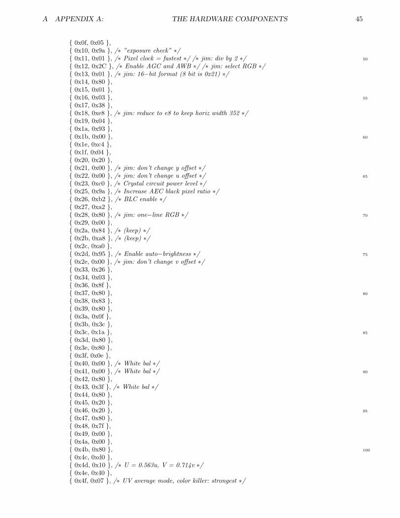
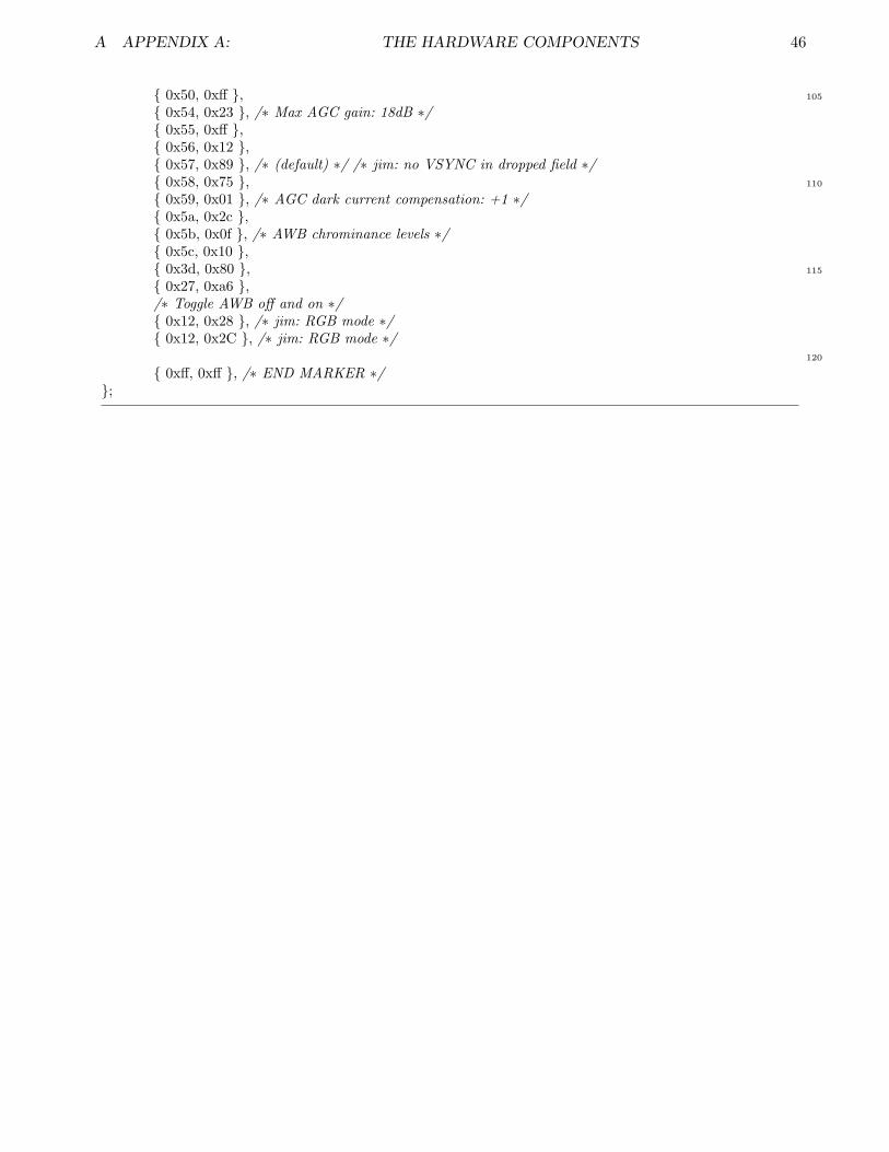
reg.h: provides the initialization value for every register on the OV6630 camera module, as wellas masks to prevent user changes to certain registers that may damage the camera physically. Thesesettings come from the Linux ov511 driver with modifications for better picture quality by Jim Paris.
Note: the initialization values shown below may not be the same values that would be read out of thecamera immediately after initialization as some registers act indirectly on others. Please consult pages20-27 of the OV6630 datasheet in article 1 of appendix C for more information about the registers andtheir actions.
/∗ Camera register data, used by cam.c ∗/
/∗ Safe register settings.If register matches first value:
5Second value is mask to apply (˜0xFF means turn off all bits)Third value is bits to force on
∗/const static struct cam safevals safe 6630[] = /∗ Allow changes to CLKRC[5:0]; if it’s set to zero,
10the rate will likely be too fast for the RAM, butit shouldn’t break. ∗/
0x11, ˜0xc0, 0x00 , /∗ Force pixel clock settings ∗/ 0x12, ˜0x80, 0x08 , /∗ Disallow reset, force RGB ∗/ 0x13, ˜0xfc, 0x00 , /∗ Force output format and tristate ∗/
15 0x20, ˜0x81, 0x00 , /∗ Don’t change HREF stuff, driver strength ∗/ 0x27, ˜0xf0, 0xa0 , /∗ Force CKOUT settings ∗/ 0x28, ˜0xc4, 0x80 , /∗ keep RGB format correct ∗/ 0x29, ˜0x40, 0x00 , /∗ master mode ∗/ 0x38, ˜0xf0, 0x80 , /∗ href settings, no overdrive ∗/
20 0xff, 0xff, 0xff , /∗ end marker ∗/;
/∗ Registers to which changes are just plain disallowed ∗/const static unsigned char disallowed 6630[] =
250x14, 0x15, 0x16, /∗ Don’t mess with output format ∗/0x23, /∗ oscillator control ∗/0x39, 0x3e, /∗ more href and timing stuff ∗/0x3f, /∗ clocks and timing ∗/0x57, /∗ charge pump ∗/
300xff /∗ end marker ∗/;
/∗ Initialization. This sequence is always sent to the camera after areset. Taken from the Linux ov511 driver, with modifications
35marked with ”jim” ∗/const static struct cam regvals init 6630[] =
0x12, 0x80 , /∗ Reset ∗/ 0x00, 0x1f , /∗ Gain ∗/ 0x01, 0x99 , /∗ Blue gain ∗/
40 0x02, 0x7c , /∗ Red gain ∗/ 0x03, 0xc0 , /∗ Saturation ∗/ 0x05, 0x0a , /∗ Contrast ∗/ 0x06, 0x95 , /∗ Brightness ∗/ 0x07, 0x2d , /∗ Sharpness ∗/
45 0x0c, 0x20 , 0x0d, 0x20 , 0x0e, 0x20 ,
A APPENDIX A: THE HARDWARE COMPONENTS 45
0x0f, 0x05 , 0x10, 0x9a , /∗ ”exposure check” ∗/
50 0x11, 0x01 , /∗ Pixel clock = fastest ∗/ /∗ jim: div by 2 ∗/ 0x12, 0x2C , /∗ Enable AGC and AWB ∗/ /∗ jim: select RGB ∗/ 0x13, 0x01 , /∗ jim: 16−bit format (8 bit is 0x21) ∗/ 0x14, 0x80 , 0x15, 0x01 ,
55 0x16, 0x03 , 0x17, 0x38 , 0x18, 0xe8 , /∗ jim: reduce to e8 to keep horiz width 352 ∗/ 0x19, 0x04 , 0x1a, 0x93 ,
60 0x1b, 0x00 , 0x1e, 0xc4 , 0x1f, 0x04 , 0x20, 0x20 , 0x21, 0x00 , /∗ jim: don’t change y offset ∗/
65 0x22, 0x00 , /∗ jim: don’t change u offset ∗/ 0x23, 0xc0 , /∗ Crystal circuit power level ∗/ 0x25, 0x9a , /∗ Increase AEC black pixel ratio ∗/ 0x26, 0xb2 , /∗ BLC enable ∗/ 0x27, 0xa2 ,
70 0x28, 0x80 , /∗ jim: one−line RGB ∗/ 0x29, 0x00 , 0x2a, 0x84 , /∗ (keep) ∗/ 0x2b, 0xa8 , /∗ (keep) ∗/ 0x2c, 0xa0 ,
75 0x2d, 0x95 , /∗ Enable auto−brightness ∗/ 0x2e, 0x00 , /∗ jim: don’t change v offset ∗/ 0x33, 0x26 , 0x34, 0x03 , 0x36, 0x8f ,
80 0x37, 0x80 , 0x38, 0x83 , 0x39, 0x80 , 0x3a, 0x0f , 0x3b, 0x3c ,
85 0x3c, 0x1a , 0x3d, 0x80 , 0x3e, 0x80 , 0x3f, 0x0e , 0x40, 0x00 , /∗ White bal ∗/
90 0x41, 0x00 , /∗ White bal ∗/ 0x42, 0x80 , 0x43, 0x3f , /∗ White bal ∗/ 0x44, 0x80 , 0x45, 0x20 ,
95 0x46, 0x20 , 0x47, 0x80 , 0x48, 0x7f , 0x49, 0x00 , 0x4a, 0x00 ,
100 0x4b, 0x80 , 0x4c, 0xd0 , 0x4d, 0x10 , /∗ U = 0.563u, V = 0.714v ∗/ 0x4e, 0x40 , 0x4f, 0x07 , /∗ UV average mode, color killer: strongest ∗/
A APPENDIX A: THE HARDWARE COMPONENTS 46
105 0x50, 0xff , 0x54, 0x23 , /∗ Max AGC gain: 18dB ∗/ 0x55, 0xff , 0x56, 0x12 , 0x57, 0x89 , /∗ (default) ∗/ /∗ jim: no VSYNC in dropped field ∗/
110 0x58, 0x75 , 0x59, 0x01 , /∗ AGC dark current compensation: +1 ∗/ 0x5a, 0x2c , 0x5b, 0x0f , /∗ AWB chrominance levels ∗/ 0x5c, 0x10 ,
115 0x3d, 0x80 , 0x27, 0xa6 ,/∗ Toggle AWB off and on ∗/ 0x12, 0x28 , /∗ jim: RGB mode ∗/ 0x12, 0x2C , /∗ jim: RGB mode ∗/
120
0xff, 0xff , /∗ END MARKER ∗/;
B APPENDIX B: THE MATLAB COMPONENTS 47
B Appendix B:The Matlab Components
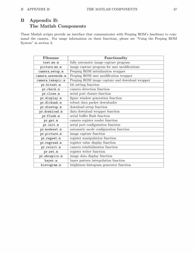
These Matlab scripts provide an interface that communicates with Peeping ROM’s hardware to com-mand the camera. For usage information on these functions, please see “Using the Peeping ROMSystem” in section 3.
Filename Functionalitytest me.m fully automatic image capture program
picture me.m image capture program for user modificationscamera setup.m Peeping ROM initialization wrapper
camera usermode.m Peeping ROM user modification wrappercamera takepic.m Peeping ROM image capture and download wrapper
pr bitset.m bit setting functionpr check.m camera detection functionpr close.m serial port closure functionpr display.m figure window generation functionpr dlchunk.m robust data packet downloaderpr dlsetup.m download setup functionpr download.m data download wrapper functionpr flush.m serial buffer flush functionpr get.m camera register reader functionpr init.m serial port configuration function
pr modeset.m automatic mode configuration functionpr picture.m image capture functionpr regset.m register manipulation functionpr regread.m register value display functionpr reinit.m camera reinitialization functionpr set.m register writer function
pr showpics.m image data display functionbayer.m bayer pattern interpolation function
histogram.m brightness histogram generator function

B APPENDIX B: THE MATLAB COMPONENTS 48
B.1 test me.m
NAME: test me – fully-automatic image capture program
CALL: test me()
INPUTS: None.
OUTPUTS: None.
DESCRIPTION: test me is a program that takes a picture with all of the Peeping ROM’sautomatic modes enabled. During the 10 second register delay period itprovides a verbose output that shows the ideal register settings to usewhen making modifications later, making it useful for capturing baselinepictures.
EXAMPLES: Typical usage – capture baseline photo.
test me;
SEE ALSO: sec 3.1

B APPENDIX B: THE MATLAB COMPONENTS 49
function data = test me()%% takes entirely automatic picture%% displays all data in verbose modedisp(’Peeping ROM test function.’);
5disp(’Hardware by Jim Paris;’);disp(’Software by Jim Paris & Andrew Muth.’);disp(’’);
%% variable setup10clear raw pic;
clear color pic;clear hist;
%% camera picture algorithm15camera setup; % <−−− set serial port here, if desired
%% automatic mode enablesdisp(’−−−−−’);pr modeset(’AEC’,’enabled’,’AGC’,’enabled’,’AWB’,’enabled’,’verbose’);
20disp(’−−−−−’);
%% display registers during settling perioddisp(’Registers displayed:’);disp(’time: 0x01 : 0x02 : 0x05 : 0x06 : 0x07 : 0x10 : 0x00’);
25for i = 10 : −1 : 1bluegain = pr get(hex2dec(’01’));redgain = pr get(hex2dec(’02’));contrast = pr get(hex2dec(’05’));brightness = pr get(hex2dec(’06’));
30sharpness = pr get(hex2dec(’07’));autoexpose = pr get(hex2dec(’10’));gain = pr get(hex2dec(’00’));disp(sprintf(’ %02d: %02X %02X %02X %02X %02X %02X %02X’,[i,bluegain,redgain,contrast,
brightness,sharpness,autoexpose,gain]));pause(1);
35end
%% capture pictureraw pic = camera takepic;
40%% image interpolation algorithm from Jim[ color pic(:,:,1) color pic(:,:,2) color pic(:,:,3) red raw green raw blue raw ] = feval(’bayer’,raw pic);
%% display raw pic, color pic, and histogrampr display(raw pic, ’Raw Data’, 1000);
45pr display(color pic, ’Final Image’, 1001);hist = histogram(color pic, 1002);
%% done workingdisp(’Done.’);
B APPENDIX B: THE MATLAB COMPONENTS 50
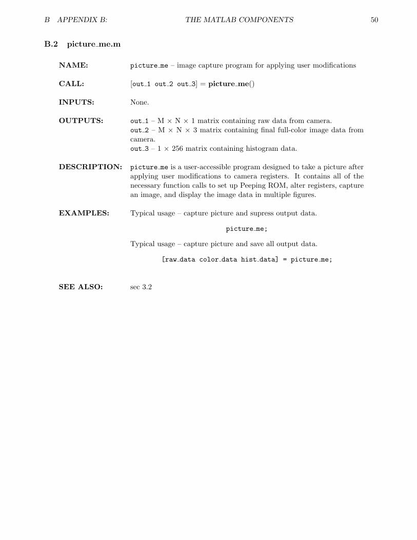
B.2 picture me.m
NAME: picture me – image capture program for applying user modifications
CALL: [out 1 out 2 out 3] = picture me()
INPUTS: None.
OUTPUTS: out 1 – M × N × 1 matrix containing raw data from camera.out 2 – M × N × 3 matrix containing final full-color image data fromcamera.out 3 – 1 × 256 matrix containing histogram data.
DESCRIPTION: picture me is a user-accessible program designed to take a picture afterapplying user modifications to camera registers. It contains all of thenecessary function calls to set up Peeping ROM, alter registers, capturean image, and display the image data in multiple figures.
EXAMPLES: Typical usage – capture picture and supress output data.
picture me;
Typical usage – capture picture and save all output data.
[raw data color data hist data] = picture me;
SEE ALSO: sec 3.2
B APPENDIX B: THE MATLAB COMPONENTS 51
function [raw pic, color pic, hist] = picture me()%% call picture me to take a picturedisp(’Peeping ROM image capture function.’);disp(’Hardware by Jim Paris;’);
5disp(’Software by Jim Paris & Andrew Muth.’);disp(’’);
%% variable initsclear raw pic;
10clear color pic;clear hist;
%% camera picture algorithmcamera setup; % <−−− set serial port here, if desired
15camera usermode(’verbose’); % <−−− enter user changes in this function!raw pic = camera takepic;
%% image interpolation algorithm from Jim[ color pic(:,:,1) color pic(:,:,2) color pic(:,:,3) red raw green raw blue raw ] = feval(’bayer’,raw pic);
20
%% display all 8 images and histogrampr showpics(raw pic, color pic, red raw, green raw, blue raw);hist = histogram(color pic, 1008);
25%% done workingdisp(’Done.’);

B APPENDIX B: THE MATLAB COMPONENTS 52
B.3 camera setup.m
NAME: camera setup – Peeping ROM initialization function
CALL: camera setup([arg 1])
INPUTS: arg 1 – optional serial port argument.
OUTPUTS: None.
DESCRIPTION: camera setup is a wrapper that calls all of the necessary intializationfunctions used to start Peeping ROM. It will pass an optional “serialport name” argument to pr init. It also checks that there is a valid,operational Peeping ROM unit responding on the opened port. Finally,it will reinitialize the camera to make sure all registers are in their correctstartup configurations.
EXAMPLES: Typical usage – initialize Peeping ROM with port autodetection.
camera setup;
Typical usage – initialize with specified serial port ‘COM3’.
camera setup(’COM3’);
SEE ALSO: sec 3.2.1
B APPENDIX B: THE MATLAB COMPONENTS 53
function data = camera setup(serialport)%%performs basic setup routines for peeping rom
%% Initialize camera5if (nargin == 1)
pr init(serialport);else
pr init;end
10
pr reinit;
B APPENDIX B: THE MATLAB COMPONENTS 54
B.4 camera usermode.m
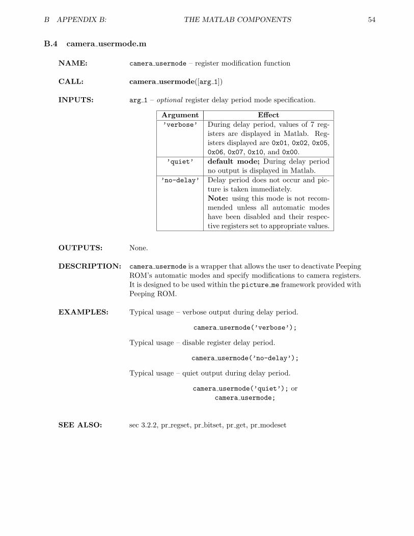
NAME: camera usermode – register modification function
CALL: camera usermode([arg 1])
INPUTS: arg 1 – optional register delay period mode specification.
Argument Effect’verbose’ During delay period, values of 7 reg-
isters are displayed in Matlab. Reg-isters displayed are 0x01, 0x02, 0x05,0x06, 0x07, 0x10, and 0x00.
’quiet’ default mode; During delay periodno output is displayed in Matlab.
’no-delay’ Delay period does not occur and pic-ture is taken immediately.Note: using this mode is not recom-mended unless all automatic modeshave been disabled and their respec-tive registers set to appropriate values.
OUTPUTS: None.
DESCRIPTION: camera usermode is a wrapper that allows the user to deactivate PeepingROM’s automatic modes and specify modifications to camera registers.It is designed to be used within the picture me framework provided withPeeping ROM.
EXAMPLES: Typical usage – verbose output during delay period.
camera usermode(’verbose’);
Typical usage – disable register delay period.
camera usermode(’no-delay’);
Typical usage – quiet output during delay period.
camera usermode(’quiet’); orcamera usermode;
SEE ALSO: sec 3.2.2, pr regset, pr bitset, pr get, pr modeset
B APPENDIX B: THE MATLAB COMPONENTS 55
function data = camera usermode(mode)%% mode setupif (nargin == 0)
mode = ’quiet’5end
%% camera automode setup:%% set ’enabled’ to ’disabled’, ’verbose’ to ’quiet’ if desireddisp(’−−−−−’);
10pr modeset(’AEC’,’enabled’,’AGC’,’enabled’,’AWB’,’enabled’,’verbose’);disp(’−−−−−’);
%% perform user−specified camera changes here%% for register changes, use:
15%% pr regset(<reg#>,<value>,[’verbose’]);%% for bitset changes, use:%% pr bitset(<reg#>,<bit#>,<value>,[’verbose’]);%% for register READS only, use:%% pr regread(<reg#>);
20disp(’Applying user−specified changes...’);%% insert changes heredisp(’−−−−−’);
%% register display during register settling period25%% enable by calling camera usermode(’verbose’)
switch modecase ’verbose’
disp(’Registers displayed:’);disp(’time: 0x01 : 0x02 : 0x05 : 0x06 : 0x07 : 0x10 : 0x00’);
30for i = 10 : −1 : 1bluegain = pr get(hex2dec(’01’));redgain = pr get(hex2dec(’02’));contrast = pr get(hex2dec(’05’));brightness = pr get(hex2dec(’06’));
35sharpness = pr get(hex2dec(’07’));autoexpose = pr get(hex2dec(’10’));gain = pr get(hex2dec(’00’));disp(sprintf(’ %02d: %02X %02X %02X %02X %02X %02X %02X’,[i,bluegain,redgain,
contrast,brightness,sharpness,autoexpose,gain]));pause(1);
40endcase ’quiet’
disp(’Please wait for register setup to finish (10 sec).’)pause(10);disp(’Setup completed.’);
45case ’no−delay’disp(’Warning: No delay period enabled!’);
pause(1);disp(’Setup completed.’);
otherwise50warning(’Unknown argument to camera usermode − using verbose mode...’);
disp(’Registers displayed:’);disp(’time: 0x01 : 0x02 : 0x05 : 0x06 : 0x07 : 0x10 : 0x00’);for i = 10 : −1 : 1
bluegain = pr get(hex2dec(’01’));55redgain = pr get(hex2dec(’02’));

B APPENDIX B: THE MATLAB COMPONENTS 56
contrast = pr get(hex2dec(’05’));brightness = pr get(hex2dec(’06’));sharpness = pr get(hex2dec(’07’));autoexpose = pr get(hex2dec(’10’));
60gain = pr get(hex2dec(’00’));disp(sprintf(’ %02d: %02X %02X %02X %02X %02X %02X %02X’,[i,bluegain,redgain,
contrast,brightness,sharpness,autoexpose,gain]));pause(1);
endend
B APPENDIX B: THE MATLAB COMPONENTS 57
B.5 camera takepic.m
NAME: camera takepic – image capture and download function
CALL: out 1 = camera takepic()
INPUTS: None.
OUTPUTS: out 1 – 349 × 288 matrix containing downloaded data from PeepingROM’s memory.
DESCRIPTION: camera takepic is a wrapper that calls a number of low-level functionsto capture an image, download it, time the download, and close any openports. This function also performs the resize operation that converts thedownloaded datastream into a properly sized matrix for display.
EXAMPLES: Typical usage – cause image capture and download.
camera takepic;
SEE ALSO: sec 3.2.3

B APPENDIX B: THE MATLAB COMPONENTS 58
function raw data = camera takepic()%% performs picture capture and download%% returns matrix with raw image info, post resizing%% into proper 349x288 image
5
%% capture picturedisp(’Starting image capture...’);pr picture;disp(’Image captured.’);
10
%% download image and resizedisp(’Downloading data...’);t start = clock;raw data = reshape(pr download(349∗288),349,288)’;
15download time = etime(clock, t start);disp(sprintf(’Total download time: %d seconds.’,[round(download time)]));
%% now close serial portpr close;
B APPENDIX B: THE MATLAB COMPONENTS 59
B.6 pr bitset.m
NAME: pr bitset – high-level bit setting function
CALL: pr bitset(arg 1, arg 2, arg 3, [arg 4])
INPUTS: arg 1 – register address to change; acceptable values from 0 to 255. Ifgiven a character string (i.e. ‘D7’) the input will be interpreted as ahexadecimal value.arg 2 – bit address to change; acceptable values from 0 (LSB) to 7(MSB).arg 3 – value to set bit with; acceptable values either 0 or 1.arg 4 – optional output mode.
Argument Effect’verbose’ Causes all internal pr regset calls
to have ‘verbose’ argument, caus-ing detailed output for each registerchange.
’quiet’ default mode; pr modeset does notprovide detailed output to screen.
OUTPUTS: None.
DESCRIPTION: pr bitset is a function designed to simplify single-bit operations for theuser. This is useful in Peeping ROM since many registers are multiplexedwith specific bits having unrelated purposes. It can set any bit in thecamera registers to either 0 or 1 with the option of a verbose outputshowing all of the individual register reads and writes.
EXAMPLES: Typical usage – setting bit 4 of register ‘2C’ to 0 with verbose output.
pr bitset(’2C’,4,0,’verbose’);
Typical usage – setting bit 7 of register 13 to 1 with no output.
pr bitset(13,7,1);
SEE ALSO: sec 3.2.2, pr regset, pr set

B APPENDIX B: THE MATLAB COMPONENTS 60
function data = pr bitset(register,bit,value,mode)%% bitwise operations on register%% call: pr regset(<reg>,<0−index−bit#>,<value>,[’verbose’/’quiet’])%% option for verbose output:
5%% <initial value, value written, new value>%% also notifies if written value isn’t read back
%% hex−>dec conversion information%% if input is character string, convert hex to dec
10%% otherwise, decimal inputif (ischar(register))
register = hex2dec(register);end
15%% actual bit setting, etcif (nargin < 3)
error(’Not enough information to set register!’);elseif (nargin == 4)
old value = pr get(register);20new value = bitset(old value,(bit+1),value);
pr regset(register,new value,mode);else
mode = ’quiet’;old value = pr get(register);
25new value = bitset(old value,(bit+1),value);pr regset(register,new value,mode);
end

B APPENDIX B: THE MATLAB COMPONENTS 61
B.7 pr check.m
NAME: pr check – internal camera detect function
CALL: pr check()
INPUTS: None.
OUTPUTS: None.
DESCRIPTION: pr check is an internal function that communicates with Peeping ROM’sPIC and camera to ensure that hardware with valid firmware is respond-ing to PC commands. It will return an error if the camera or host PICcontroller is not responding, or if the hardware’s firmware version is in-correct.
EXAMPLES: Typical usage – check for responsive camera.
pr check;
SEE ALSO: n/a

B APPENDIX B: THE MATLAB COMPONENTS 62
function pr check(verbose)
if(nargin < 1)verbose = 1;
5end
global pr serialobj;pr flush;
10%% If no format string is specified, ’%s\n’ is assumed.%% Specify it manually to avoid confusion.fprintf(pr serialobj, ’%s\n’, ’V’);line = fgetl(pr serialobj);if(strncmp(line,’ver ’,4) == 0)
15pr close;error ’Invalid or no response from camera. Check connections.’;
endif(strcmp(line,’ver 02’) == 0)
pr close;20error(’Wrong camera firmware version ”%s”, expected ”ver 02”’,line);
endif(verbose)
disp(’Camera firmware 02 detected.’);end

B APPENDIX B: THE MATLAB COMPONENTS 63
B.8 pr close.m
NAME: pr close – internal serial port closing function
CALL: pr close()
INPUTS: None.
OUTPUTS: None.
DESCRIPTION: pr close is an internal function used to close a serial port opened usingpr init.
EXAMPLES: Typical usage – close serial port.
pr close;
SEE ALSO: pr init

B APPENDIX B: THE MATLAB COMPONENTS 64
function pr closeclear global pr serialobj;global pr serialobj;
5ports=instrfind;if isobject(ports)
stopasync(ports);fclose(ports);delete(ports);
10disp(’Closed serial port.’);end

B APPENDIX B: THE MATLAB COMPONENTS 65
B.9 pr display.m
NAME: pr display – internal figure generation function
CALL: pr display(arg 1, [arg 2, arg 3])
INPUTS: arg 1 – data matrix to be displayed; either M × N × 1 or M × N × 3.arg 2 – optional string containing figure name to be displayed in titlebar of window; will default to “Image” if not specified.arg 3 – optional figure number to use; will default to 4321 if not specified.
OUTPUTS: None.
DESCRIPTION: pr display is an internal function that takes a data matrix and createsan appropriate figure window for it. It allows for specifying the figurewindow name and ID number, performs 1:1 resizing, and colorizes animage if necessary. If the figure number of an existing window is supplied,the new image will refresh in the existing window rather than spawninga new one. Also, if the image data in arg 1 is a single-plane matrix(M × N × 1) it will be rendered in grayscale with 0 being black and 255being white. All other image data will be rendered in color with the firstlayer being red, the second green, and the third blue.
EXAMPLES: Typical usage – display matrix raw data in figure 1001 with name “RawData Image”.
pr display(raw data,’Raw Data Image’, 1001);
SEE ALSO: pr showpics

B APPENDIX B: THE MATLAB COMPONENTS 66
function pr display(data, fig name, fig number)
%% Display a peeping rom image in figure window fig number (or 4321)%% Pass either a NxM matrix to display as greyscale, or
5%% a NxMx3 matrix to display as red, green, blue.%% also pass figure name as string
[ row, col, planes ] = size(data);if planes ˜= 1 && planes ˜= 3
10error ”Bad image data format”end
%% Bring figure to front, display image, and resizeif (nargin ˜= 3)
15fig = figure(4321);elseif (nargin == 3)
fig = figure(fig number);else
warning(’No figure name or number passed to pr display.’);20fig name = ’Image’;
fig = figure(4321);end
clf;25image(uint8(data));
if planes == 1%% Display as grayscalecolormap(gray(256));
end30rect = get(fig, ’Position’);
set(fig, ’Position’, [rect(1), rect(2), col, row]);set(fig, ’Resize’, ’on’);set(fig, ’Name’, sprintf(’Peeping ROM − %s’,[fig name]));set(fig, ’NumberTitle’, ’off’);
35ha = gca;set(ha, ’Units’, ’Normalized’);axis image;axis off;set(ha, ’Position’, [0, 0, 1, 1]);

B APPENDIX B: THE MATLAB COMPONENTS 67
B.10 pr download.m
NAME: pr download – internal image download function
CALL: out 1 = pr download(arg 1, arg 2, arg 3)
INPUTS: arg 1 – number of bytes to be downloaded; acceptable values between 0and 512KB.arg 2 – optional RAM address to start download at.arg 3 – optional verbose flag to cause error data printing on-screen.
OUTPUTS: out 1 – arg 1 × 1 matrix containing all of the downloaded data, firstbyte received at (1, 1).
DESCRIPTION: pr download is an internal function that performs all of the softwareactions needed to download image data from Peeping ROM’s SRAM.To prevent missed data frames this function requests data in 128-bytepackets. Every 5 seconds the percentage downloaded is displayed inMatlab. It will return an error if an invalid number of databytes isgiven, if port setup fails, or if there is an error while downloading thedata.
EXAMPLES: Typical usage – download 349 × 288 bytes of image data with verboseflag.
raw data = pr download(349*288,0,’verbose’);
raw pic now contains 100,512 bytes of data in a 101,512 × 1 matrix.
SEE ALSO: camera takepic, pr dlchunk, pr dlsetup

B APPENDIX B: THE MATLAB COMPONENTS 68
function data = pr download(num, addr, mode)
%% Check argumentsif(nargin < 1 || num < 1 || num > 512∗1024 || num ˜= floor(num))
5error ’Invalid number of bytes.’;end
if(nargin < 2)addr = 0;
10end
if(nargin < 3)mode = ’quiet’;
end15
if(addr < 0 || addr >= 512∗1024 || addr ˜= floor(addr))error ’Invalid starting address.’;
end
20global pr serialobj;pr flush;pr dlsetup(addr);tic;chunksize = 128; % must match PIC chunk size
25
%% Download the data in chunksdata = zeros(num,1);for start = 1:chunksize:num
%% Print status every 5 seconds30if toc > 5
disp(sprintf(’%6.2f%% complete’,start/num ∗ 100));tic
endcount = chunksize;
35bytes = pr dlchunk(count, addr + start − 1, mode);if (start + 128) > num
count = num − start + 1;enddata(start:(start + count − 1)) = bytes(1 : count);
40enddisp(sprintf(’%6.2f%% complete’,100));
%% Exit download modefprintf(pr serialobj, ’%s\n’, ’X’);
45line = fgetl(pr serialobj);

B APPENDIX B: THE MATLAB COMPONENTS 69
B.11 pr dlchunk.m
NAME: pr dlchunk – packet download and error correction function
CALL: out 1 = pr dlchunk(arg 1, arg 2, arg 3)
INPUTS: arg 1 – packet size (in data bytes) to receive.arg 2 – starting address of the data packet in RAM.arg 3 – optional verbose flag to display any serial reception errors.
OUTPUTS: out 1 – matrix of size arg 1×3− 1 containing downloaded line of data.
DESCRIPTION: pr dlchunk is an internal function that downloads a small packet ofthe total image data. It contains error correction routines that willredownload data if it is corrupted with a frameshift error.
EXAMPLES: Typical usage – download 128 databytes of data from address 0 onwards.
bytes = pr dlchunk(128,0,’verbose’);
SEE ALSO: pr download, pr dlsetup

B APPENDIX B: THE MATLAB COMPONENTS 70
function bytes = pr dlchunk(size, addr, mode)%% Download a chunk of specified size, retrying if there’s an error.%% Assumes the download has been initialized, and reinitializes to%% the given address only if it needs to retry.
5
if(nargin < 3)mode = ’quiet’;
end
10if(size < 1)error ’Invalid chunk size.’;
endlinesize = size ∗ 3 − 1;
15if(addr < 0 || addr >= 512∗1024 || addr ˜= floor(addr))error ’Invalid starting address.’;
end
global pr serialobj;20pr flush;
bad = 1;while bad
bad = 0;25fprintf(pr serialobj, ’%s\n’, ’M’);
line = fgetl(pr serialobj);if(length(line) ˜= linesize)
if(mode == ’verbose’)disp(sprintf(’Warning: only got %d characters, wanted %d’, ...
30length(line), linesize));endbad = 1;
else[bytes, count] = sscanf(line, ’%02x’);
35if(count ˜= size)if(mode == ’verbose’)
disp(sprintf(’Warning: only got %d data bytes, wanted %d’, ...count, size));
end40bad = 1;
endendif(bad)
%% reinitialize download45if(mode == ’verbose’)
disp(sprintf(’Retrying download at address %06x’,addr));endpr check(0);pr dlsetup(addr);
50endend
B APPENDIX B: THE MATLAB COMPONENTS 71
B.12 pr dlsetup.m
NAME: pr dlsetup – RAM address setup function
CALL: pr dlsetup(arg 1);
INPUTS: arg 1 – RAM address to be set.
OUTPUTS: None.
DESCRIPTION: pr dlsetup is an internal function that sets the address counter of Peep-ing ROM’s SRAM to the value arg 1. Since this process involves incre-menting the RAM to the proper address a high value in arg 1 may take ashort amount of time to complete. It also commands the PIC controllerto prepare for the bulk downloading of data from SRAM. It will generatean error if the download command fails.
EXAMPLES: Typical usage – set RAM address to 1234.
pr dlsetup(1234);
SEE ALSO: pr download, pr dlchunk

B APPENDIX B: THE MATLAB COMPONENTS 72
function pr dlsetup(addr)%% Initialize download at specified address
if(addr < 0 || addr >= 512∗1024 || addr ˜= floor(addr))5error ’Invalid starting address.’;
end
global pr serialobj;pr flush;
10
%% Setup the downloadcmd = sprintf(’D%06x’, addr);fprintf(pr serialobj, ’%s\n’, cmd);line = fgetl(pr serialobj);
15if(strcmp(line,’ok’) == 0)error ’Download setup failed.’;
end
B APPENDIX B: THE MATLAB COMPONENTS 73
B.13 pr flush.m
NAME: pr flush – internal serial buffer flushing function
CALL: pr flush()
INPUTS: None.
OUTPUTS: None.
DESCRIPTION: pr flush is an internal Peeping ROM function used to empty the serialinput buffer before sending a new command. It will return an error if noport is open.
EXAMPLES: Typical usage – clearing port buffer.
pr flush;
SEE ALSO: pr init

B APPENDIX B: THE MATLAB COMPONENTS 74
function pr flush()
global pr serialobj;
5if ˜isobject(pr serialobj)error ’Port not open.’;
end
while pr serialobj.BytesAvailable > 010c = fscanf(pr serialobj,’%c’,1);
end

B APPENDIX B: THE MATLAB COMPONENTS 75
B.14 pr get.m
NAME: pr get – high-level register reading function
CALL: out 1 = pr get(arg 1)
INPUTS: arg 1 – register address to be read. Accepts value between 0 and 255.If input is a character string (i.e. ‘F3’), string is interpreted as hexadec-imal.
OUTPUTS: out 1 – value read from register at address arg 1.
DESCRIPTION: pr get is a user-accessible function that reads the value of any registerin Peeping ROM’s camera. It will return an error if the read fails.
EXAMPLES: Typical usage – read value of register 37 (in hex, ’25’)
foo = pr get(’25’);
The variable foo now contains the value of register 37.
SEE ALSO: pr regset, sec 3.2.2
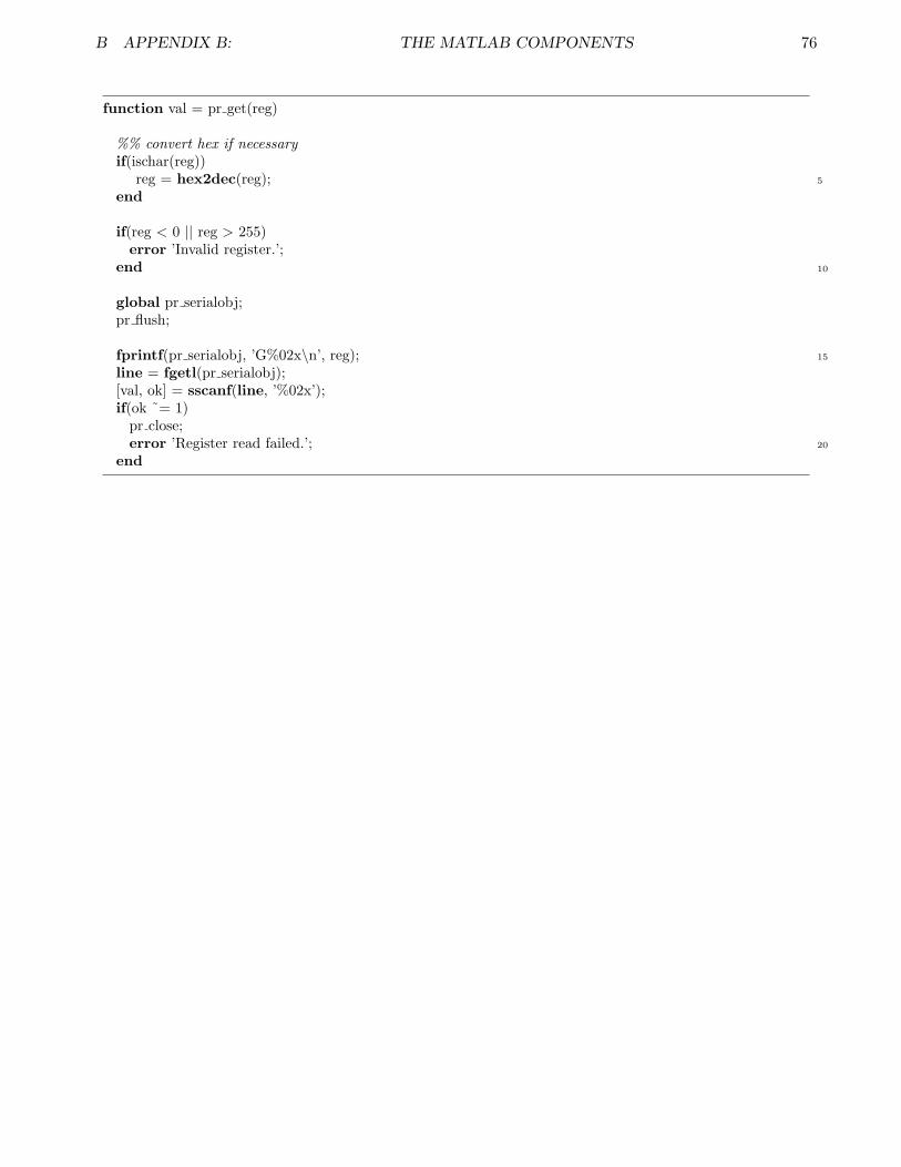
B APPENDIX B: THE MATLAB COMPONENTS 76
function val = pr get(reg)
%% convert hex if necessaryif(ischar(reg))
5reg = hex2dec(reg);end
if(reg < 0 || reg > 255)error ’Invalid register.’;
10end
global pr serialobj;pr flush;
15fprintf(pr serialobj, ’G%02x\n’, reg);line = fgetl(pr serialobj);[val, ok] = sscanf(line, ’%02x’);if(ok ˜= 1)
pr close;20error ’Register read failed.’;
end

B APPENDIX B: THE MATLAB COMPONENTS 77
B.15 pr init.m
NAME: pr init – internal serial port initialization
CALL: pr init(arg 1)
INPUTS: arg 1 – optional character string of serial port name, i.e. ’COM2’ or’/dev/tty0’.
OUTPUTS: None.
DESCRIPTION: pr init is an internal function that performs automatic serial port de-tection and setup. If a port is not specified as arg 1, it will determinethe computer OS and attempt to open the default serial port. In theevent that Matlab cannot open that port, it will prompt the user to in-put a port name. Serial format is 115.2kbps, 8N1 (8 data bits, no parity,1 stop bit).
EXAMPLES: Typical usage – use serial port autodetect.
pr init;
Typical usage – serial port ID is COM3.
pr init(’COM3’);
SEE ALSO: camera setup
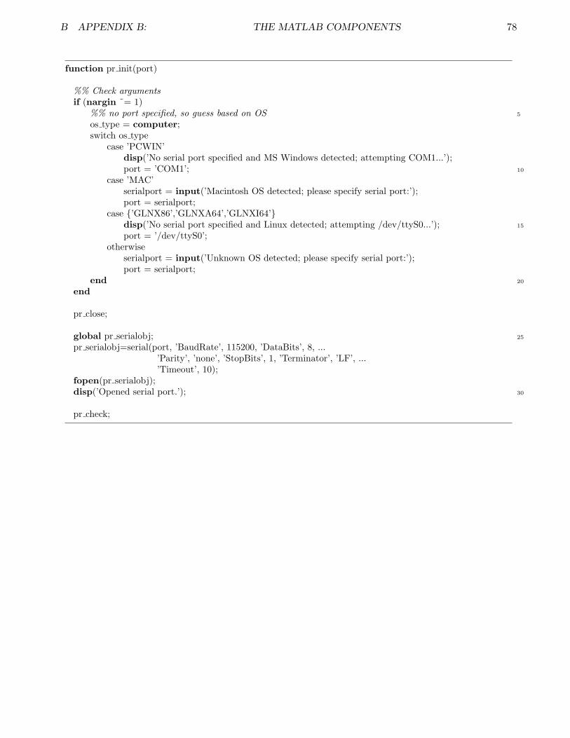
B APPENDIX B: THE MATLAB COMPONENTS 78
function pr init(port)
%% Check argumentsif (nargin ˜= 1)
5%% no port specified, so guess based on OSos type = computer;switch os type
case ’PCWIN’disp(’No serial port specified and MS Windows detected; attempting COM1...’);
10port = ’COM1’;case ’MAC’
serialport = input(’Macintosh OS detected; please specify serial port:’);port = serialport;
case ’GLNX86’,’GLNXA64’,’GLNXI64’15disp(’No serial port specified and Linux detected; attempting /dev/ttyS0...’);
port = ’/dev/ttyS0’;otherwise
serialport = input(’Unknown OS detected; please specify serial port:’);port = serialport;
20endend
pr close;
25global pr serialobj;pr serialobj=serial(port, ’BaudRate’, 115200, ’DataBits’, 8, ...
’Parity’, ’none’, ’StopBits’, 1, ’Terminator’, ’LF’, ...’Timeout’, 10);
fopen(pr serialobj);30disp(’Opened serial port.’);
pr check;

B APPENDIX B: THE MATLAB COMPONENTS 79
B.16 pr modeset.m
NAME: pr modeset – high-level automatic mode configuration function
CALL: pr modeset(arg 1, arg 2, arg 3, arg 4, arg 5, arg 6, [arg 7])
INPUTS: arg 1, arg 3, arg 5 – automode options (any order).
Argument System’AWB’ Automatic White Balancing. If en-
abled, controls register 0x06 (BRT).’AEC’ Automatic Exposure Control. If en-
abled, controls register 0x10 (AEC).’AGC’ Automatic Gain Control. If enabled,
controls registers 0x00 (GAIN), 0x01(BLUE), 0x02 (RED).
arg 2, arg 4, arg 6 – mode options.
Argument Effect’enabled’ default mode; Causes automatic
system to change camera registers(overwriting user changes) and effectimage qualities.
’disabled’ Deactivates internal circuits of spec-ified system. Effected registers cannow be altered by user without fearof internal overwrites.
arg 7 – optional output mode.
Argument Effect’verbose’ Causes all internal pr regset calls
to have ‘verbose’ argument, caus-ing detailed output for each registerchange.
’quiet’ default mode; pr modeset does notprovide detailed output to screen.
OUTPUTS: None.
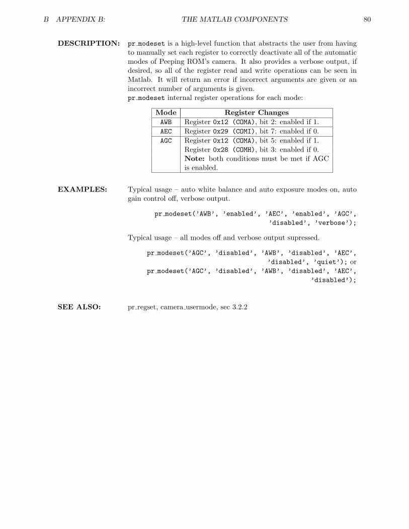
B APPENDIX B: THE MATLAB COMPONENTS 80
DESCRIPTION: pr modeset is a high-level function that abstracts the user from havingto manually set each register to correctly deactivate all of the automaticmodes of Peeping ROM’s camera. It also provides a verbose output, ifdesired, so all of the register read and write operations can be seen inMatlab. It will return an error if incorrect arguments are given or anincorrect number of arguments is given.pr modeset internal register operations for each mode:
Mode Register ChangesAWB Register 0x12 (COMA), bit 2: enabled if 1.AEC Register 0x29 (COMI), bit 7: enabled if 0.AGC Register 0x12 (COMA), bit 5: enabled if 1.
Register 0x28 (COMH), bit 3: enabled if 0.Note: both conditions must be met if AGCis enabled.
EXAMPLES: Typical usage – auto white balance and auto exposure modes on, autogain control off, verbose output.
pr modeset(’AWB’, ’enabled’, ’AEC’, ’enabled’, ’AGC’,’disabled’, ’verbose’);
Typical usage – all modes off and verbose output supressed.
pr modeset(’AGC’, ’disabled’, ’AWB’, ’disabled’, ’AEC’,’disabled’, ’quiet’); or
pr modeset(’AGC’, ’disabled’, ’AWB’, ’disabled’, ’AEC’,’disabled’);
SEE ALSO: pr regset, camera usermode, sec 3.2.2

B APPENDIX B: THE MATLAB COMPONENTS 81
function data = pr modeset(mode 1,state 1,mode 2,state 2,mode 3,state 3,mode)%% Sets up entire automode system and gives%% back useful info to the operator.%% Expects variable number of arguments of type
5%% <system>,<status> −−> ...’AEC’,’disable’,...%% AEC, AWB, AGC options
% starts with all modes enabled!disp(’NOTE: all automatic modes are enabled on startup!’);
10
for i = 1:(nargin/2)%% sets right arguments into variables for testingif (nargin < 7)
mode = ’quiet’;15end
if ((nargin > 7) | ((nargin ˜= 7) & (mod(nargin,2) ˜= 0)))error(’%d arguments supplied to pr modeset; 3 argument PAIRS expected.’,nargin);
elseif (i == 1)x = mode 1;
20y = state 1;elseif (i == 2)
x = mode 2;y = state 2;
elseif (i == 3)25x = mode 3;
y = state 3;end%% parses arguments and sets camera%% NOTE! bitset(..) is 1−indexed, while OV6630 datasheet is
30%% 0−indexed!switch x
case ’AEC’%% register 0x29: COMI[7] is AEC DISABLE if 1switch y
35case ’enabled’ %COMI[7] = 0old value = pr get(hex2dec(’29’));new value = bitset(old value,8,0);pr regset(’29’,new value,mode);disp(’Auto Exposure Control operational.’);
40case ’disabled’ %COMI[7] = 1old value = pr get(hex2dec(’29’));new value = bitset(old value,8,1);pr regset(’29’,new value,mode);disp(’Auto Exposure Control disabled.’);
45otherwiseerror(’%s is not an allowed option.’,y);
endcase ’AWB’
switch y50%% register 0x12: COMA[2] is AWB ENABLE if 1
case ’enabled’ %COMA[2] = 1old value = pr get(hex2dec(’12’));new value = bitset(old value,3,1);pr regset(’12’,new value,mode);
55disp(’Auto White Balance operational.’);case ’disabled’ %COMA[2] = 0

B APPENDIX B: THE MATLAB COMPONENTS 82
old value = pr get(hex2dec(’12’));new value = bitset(old value,3,0);pr regset(’12’,new value,mode);
60disp(’Auto White Balance disabled.’);otherwise
error(’%s is not an allowed option.’,y);end
case ’AGC’65switch y
%% register 0x12: COMA[5] is AGC ENABLE if 1%% register 0x28: COMH[3] is AGC DISABLE if 1case ’enabled’ %COMA[5] = 1; COMH[3] = 0
old value = pr get(hex2dec(’12’));70new value = bitset(old value,6,1);
pr regset(’12’,new value,mode);old value = pr get(hex2dec(’28’));new value = bitset(old value,4,0);pr regset(’28’,new value,mode);
75disp(’Auto Gain Control operational.’);case ’disabled’ %COMA[5] = 0; COMH[3] = 1
old value = pr get(hex2dec(’12’));new value = bitset(old value,6,0);pr regset(’12’,new value,mode);
80old value = pr get(hex2dec(’28’));new value = bitset(old value,4,1);pr regset(’28’,new value,mode);disp(’Auto Gain Control disabled.’);
otherwise85error(’%s is not an allowed option.’,y);
endotherwise
error(’%s is not an allowed option.’,x);end
90end

B APPENDIX B: THE MATLAB COMPONENTS 83
B.17 pr picture.m
NAME: pr picture – internal image capture function
CALL: pr picture()
INPUTS: None.
OUTPUTS: None.
DESCRIPTION: pr picture is an internal function that sends the “capture next availableframe” command string to the PIC host controller. It will return an errorif the PIC fails to capture an image successfully.
EXAMPLES: Typical usage – capture next image.
pr picture;
SEE ALSO: camera takepic

B APPENDIX B: THE MATLAB COMPONENTS 84
function pr picture()
global pr serialobj;pr flush;
5
fprintf(pr serialobj, ’%s\n’, ’P’);line = fgetl(pr serialobj);if(strcmp(line,’ok’) == 0)
pr close;10error ’Capture failed.’;
enddisp(’Captured picture.’);

B APPENDIX B: THE MATLAB COMPONENTS 85
B.18 pr regset.m
NAME: pr regset – high-level register setting function
CALL: pr regset(arg 1, arg 2, [arg 3])
INPUTS: arg 1 – register to be changed. If given a string input (i.e. ‘B7’)pr regset will interpret this as a hexadecimal value; otherwise will in-terpret as a decimal value.arg 2 – value to be set in register. Like arg 1, character string inputwill be interpreted as hexadecimal.arg 3 – optional argument that changes output mode of pr regset.Options include:
Value Output Behavior‘verbose’ Causes text output in Matlab terminal
showing all register operations per-formed during register value set.
‘quiet’ default mode; No text output isshown in Matlab unless an error is de-tected.
This argument is not necessary for proper operation, however, and canbe left out during the function call.
OUTPUTS: None.
DESCRIPTION: pr regset is the register modification function provided so the user canalter any of the camera registers. It allows multiple input formats and averbose output of the form
Register <reg number>: originally <old val>, set to <newval>, new value <readback val>.
Regardless of mode setting, text output will occur if the value sent to theregister is not identical to the value read back after the write operationoccurs. However, since this behavior is expected for some registers thiswarning will not cause an image capture to fail.
EXAMPLES: Typical usage – change register ‘2E’ to 63 while seeing verbose output.
pr regset(’2E’,63,’verbose’);
SEE ALSO: sec 3.2.2, pr modeset, pr set
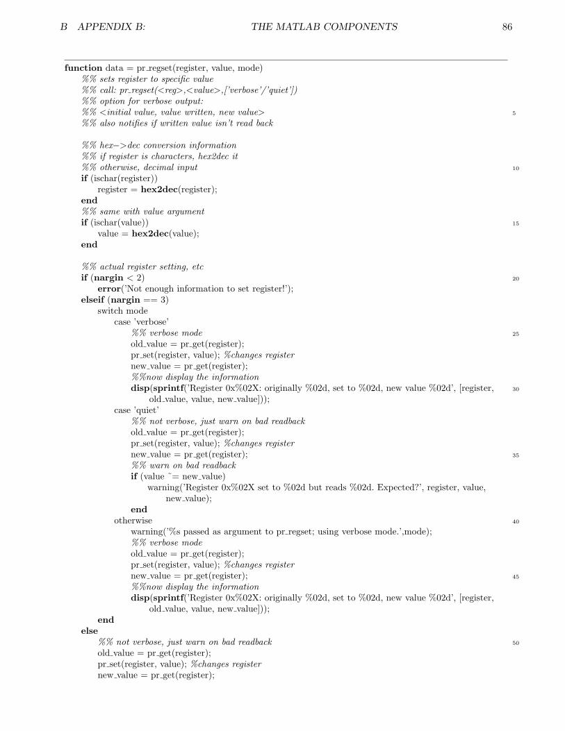
B APPENDIX B: THE MATLAB COMPONENTS 86
function data = pr regset(register, value, mode)%% sets register to specific value%% call: pr regset(<reg>,<value>,[’verbose’/’quiet’])%% option for verbose output:
5%% <initial value, value written, new value>%% also notifies if written value isn’t read back
%% hex−>dec conversion information%% if register is characters, hex2dec it
10%% otherwise, decimal inputif (ischar(register))
register = hex2dec(register);end%% same with value argument
15if (ischar(value))value = hex2dec(value);
end
%% actual register setting, etc20if (nargin < 2)
error(’Not enough information to set register!’);elseif (nargin == 3)
switch modecase ’verbose’
25%% verbose modeold value = pr get(register);pr set(register, value); %changes registernew value = pr get(register);%%now display the information
30disp(sprintf(’Register 0x%02X: originally %02d, set to %02d, new value %02d’, [register,old value, value, new value]));
case ’quiet’%% not verbose, just warn on bad readbackold value = pr get(register);pr set(register, value); %changes register
35new value = pr get(register);%% warn on bad readbackif (value ˜= new value)
warning(’Register 0x%02X set to %02d but reads %02d. Expected?’, register, value,new value);
end40otherwise
warning(’%s passed as argument to pr regset; using verbose mode.’,mode);%% verbose modeold value = pr get(register);pr set(register, value); %changes register
45new value = pr get(register);%%now display the informationdisp(sprintf(’Register 0x%02X: originally %02d, set to %02d, new value %02d’, [register,
old value, value, new value]));end
else50%% not verbose, just warn on bad readback
old value = pr get(register);pr set(register, value); %changes registernew value = pr get(register);

B APPENDIX B: THE MATLAB COMPONENTS 87
%% warn on bad readback55if (value ˜= new value)
warning(’Register 0x%02X set to %02d but reads %02d. Expected?’, register, value, new value);end
end

B APPENDIX B: THE MATLAB COMPONENTS 88
B.19 pr regread.m
NAME: pr regread – high-level register value display function
CALL: pr regread(arg 1)
INPUTS: arg 1 – register address to be displayed; if character string is given it isinterpreted as hexadecimal.
OUTPUTS: None.
DESCRIPTION: pr regread is a function that prints the value of a register in the Matlabterminal.
EXAMPLES: Typical usage – display value of register ‘B2’.
pr regread(’2E’);
SEE ALSO: camera usermode
B APPENDIX B: THE MATLAB COMPONENTS 89
function pr regread(reg)%% register value reporting function
%% hex−>dec conversion information5%% if input is character string, convert hex to dec
%% otherwise, decimal inputif(ischar(reg))
reg = hex2dec(reg);end
10
%% now display the register valuedisp(sprintf(’Register 0x%02X = %02d.’,[reg, pr get(reg)]));

B APPENDIX B: THE MATLAB COMPONENTS 90
B.20 pr reinit.m
NAME: pr reinit – internal camera reinitialization function
CALL: pr reinit()
INPUTS: None.
OUTPUTS: None.
DESCRIPTION: pr reinit causes the camera to reset. It is used once per image captureto ensure the camera is in a stable state before applying user changesand recording a photo.Note: reinitialization causes all registers to revert back to initial valuesspecified in reg.h.
EXAMPLES: Typical usage – cause camera reinitialization.
pr reinit;
SEE ALSO: reg.h, camera setup

B APPENDIX B: THE MATLAB COMPONENTS 91
function pr reinit()
global pr serialobj;pr flush;
5
fprintf(pr serialobj, ’%s\n’, ’R’);line = fgetl(pr serialobj);if(strcmp(line,’ok’) == 0)
pr close;10error ’Camera reinitialization failed.’;
enddisp(’Camera reinitialized.’);
B APPENDIX B: THE MATLAB COMPONENTS 92
B.21 pr set.m
NAME: pr set – internal register value setting function
CALL: pr set(arg 1, arg 2)
INPUTS: arg 1 – register to be set; value from 0 to 255 allowed.arg 2 – value register will be set to.
OUTPUTS: None.
DESCRIPTION: pr set communicates with the PIC to set a specified register to a par-ticular value. It will cause an error if readback from the camera fails oran invalid register number is given.Note: this function is not intended for use by the user; please use theimproved function pr regset instead.
EXAMPLES: Typical usage – setting register 24 to 128.
pr set(24,128);
SEE ALSO: pr regset
B APPENDIX B: THE MATLAB COMPONENTS 93
function val = pr set(reg, setval)
if(reg < 0 || reg > 255)error ’Invalid register.’;
5end
global pr serialobj;pr flush;
10fprintf(pr serialobj, ’S%02x%02x\n’, [reg; setval]);line = fgetl(pr serialobj);[val, ok] = sscanf(line, ’%02x’);if(ok ˜= 1)
pr close;15error ’Register readback failed.’;
end
B APPENDIX B: THE MATLAB COMPONENTS 94
B.22 pr showpics.m
NAME: pr showpics – high-level multi-image display function
CALL: pr showpics(arg 1, arg 2, arg 3, arg 4, arg 5)
INPUTS: arg 1 – M × N × 1 matrix containing integers 0 through 255 that willbe displayed as the raw camera data.arg 2 – M × N × 3 matrix containing integers 0 through 255; data willbe displayed as the final interpolated color image with red channel being(:, :, 1), green being (:, :, 2), blue being (:, :, 3).arg 3 – M × N × 1 matrix containing integers 0 through 255 that willbe displayed as the raw red channel data.arg 4 – M × N × 1 matrix containing integers 0 through 255 that willbe displayed as the raw green channel data.arg 5 – M × N × 1 matrix containing integers 0 through 255 that willbe displayed as the raw blue channel data.
OUTPUTS: None.
DESCRIPTION: pr showpics generates all of Peeping ROM’s output images. It callspr display for actual figure generation. It also specifies figure numbersfor each image so any subsequent pictures taken with Peeping ROM willrefresh into those windows rather than spawning more.
EXAMPLES: See picture me or automode for usage examples.
SEE ALSO: picture me, automode, pr display, sec 3.5

B APPENDIX B: THE MATLAB COMPONENTS 95
function data = camera showpics(raw image, color image, red raw, green raw, blue raw)%% shows 5 photos for each picture taken:%% raw−red, raw−green, raw−blue,%% bayer−red, bayer−green, bayer−blue
5%% raw−bw, bayer−bw, full−image%% uses figures 1000−1008%% assumes MxN matrix for raw, MxNx3 for colordisp(’Displaying all image data...’);
10%% after interpolation using bayerr raw = zeros(length(red raw(:,1)),length(red raw),3);r raw(:,:,1) = red raw(:,:,1);g raw = zeros(length(green raw(:,1)),length(green raw),3);g raw(:,:,2) = green raw(:,:,1);
15b raw = zeros(length(blue raw(:,1)),length(blue raw),3);b raw(:,:,3) = blue raw(:,:,1);
%% after interpolation using bayerred channel = zeros(length(color image(:,1)),length(color image),3);
20red channel(:,:,1) = color image(:,:,1);green channel = zeros(length(color image(:,1)),length(color image),3);green channel(:,:,2) = color image(:,:,2);blue channel = zeros(length(color image(:,1)),length(color image),3);blue channel(:,:,3) = color image(:,:,3);
25
%% now display everythingpr display(raw image, ’Raw Data’, 1000);pr display(r raw, ’Raw Red Channel’, 1001);pr display(g raw, ’Raw Green Channel’, 1002);
30pr display(b raw, ’Raw Blue Channel’, 1003);pr display(red channel, ’Post−Bayer Red Channel’, 1004);pr display(green channel, ’Post−Bayer Green Channel’, 1005);pr display(blue channel, ’Post−Bayer Blue Channel’, 1006);pr display(color image, ’Final Interpolated Image’, 1007);

B APPENDIX B: THE MATLAB COMPONENTS 96
B.23 bayer.m
NAME: bayer – high-level bayer pattern interpolation function
CALL: [out 1 out 2 out 3 out 4 out 5 out 6] = bayer(arg 1)
INPUTS: arg 1 – an M × N × 1 matrix containing integers from 0 to 255; typicallyraw data from camera.
OUTPUTS: out 1 – M × N matrix containing interpolated data from red pixel lo-cations in bayer pattern; values from 0 to 255. Becomes red channel offinal image.out 2 – M × N matrix containing interpolated data from green pixellocations in bayer pattern; values from 0 to 255. Becomes green channelof final image.out 3 – M × N matrix containing interpolated data from blue pixellocations in bayer pattern; values from 0 to 255. Becomes blue channelof final image.out 4 – M × N matrix containing raw data from red pixel locations inbayer pattern; values from 0 to 255. Non-red pixel locations containvalue of 0.out 5 – M × N matrix containing raw data from green pixel locations inbayer pattern; values from 0 to 255. Non-green pixel locations containvalue of 0.out 6 – M × N matrix containing raw data from blue pixel locations inbayer pattern; values from 0 to 255. Non-blue pixel locations containvalue of 0.
DESCRIPTION: bayer performs a simple averaging-type bayer interpolation on a datamatrix. It also provides access to all of the raw data channels (R,G,B)coming from the camera.
EXAMPLES: See picture me and automode for usage examples.
SEE ALSO: sec 3.3, picture me, automode
B APPENDIX B: THE MATLAB COMPONENTS 97
function [r, g, b, or, og, ob] = bayer(c)%%% Given n x m matrix of Bayer−patterned data from camera, return three%%% n x m matrices representing the per−pixel interpolated RGB values.%%% All data should be integers 0−255. Interpolation is linear, and
5%%% expected pattern is%%% G B G B G B%%% R G R G R G%%% G B G B G B%%% R G R G R G
10%%% written 01/2005 by Jim Paris <[email protected]>[m,n] = size(c);if(m<2 | n<2) error(’image too small’); end;r = zeros(m,n);g = zeros(m,n);
15b = zeros(m,n);
xO = 1:2:n; yO = 1:2:m; % all odd indicesxE = 2:2:n; yE = 2:2:m; % all even indicesxo = 3:2:n−1; yo = 3:2:m−1; % odd indices except border
20xe = 2:2:n−1; ye = 2:2:m−1; % even indices except border
%% Set known RGB values from Bayer patterng(yO,xO) = c(yO,xO); b(yO,xE) = c(yO,xE);r(yE,xO) = c(yE,xO); g(yE,xE) = c(yE,xE);
25
%% Provide the uninterpolated values to the useror = r;og = g;ob = b;
30
%%%% Do the bulk of the interpolation:
%% Interpolate red: 2 3%% R 1
35r(yE,xe) = (r(yE,xe−1) + r(yE,xe+1)) / 2; % 1r(yo,xO) = (r(yo−1,xO) + r(yo+1,xO)) / 2; % 2r(yo,xe) = (r(yo−1,xe−1) + r(yo−1,xe+1) + r(yo+1,xe−1) + r(yo+1,xe+1))/4; % 3
%% Interpolate green: G 140%% 2 G
g(yo,xe) = (g(yo,xe−1) + g(yo,xe+1) + g(yo−1,xe) + g(yo+1,xe))/4; % 1g(ye,xo) = (g(ye,xo−1) + g(ye,xo+1) + g(ye−1,xo) + g(ye+1,xo))/4; % 2
%% Interpolate blue: 1 B45%% 3 2
b(yO,xo) = (b(yO,xo−1) + b(yO,xo+1)) / 2; % 1b(ye,xE) = (b(ye−1,xE) + b(ye+1,xE)) / 2; % 2b(ye,xo) = (b(ye−1,xo−1) + b(ye−1,xo+1) + b(ye+1,xo−1) + b(ye+1,xo+1))/4; % 3
50%%%% Now fix up the edge cases on the borders:
%% Red: copy line to top, and maybe bottom and rightr(1,:) = r(2,:);if( mod(m,2)) r(m,:) = r(m−1,:); end;
55if(˜mod(n,2)) r(:,n) = r(:,n−1); end;
B APPENDIX B: THE MATLAB COMPONENTS 98
%% Green: average three pixels at border: G 1 G%% This is the messy case. 2 G .%% First do top and left G . .
60g(1,xe) = (g(2,xe) + g(1,xe−1) + g(1,xe+1))/3; % 1g(ye,1) = (g(ye,2) + g(ye−1,1) + g(ye+1,1))/3; % 2if(mod(m,2)) % Bottom is G 1 G 1
g(m,xe) = (g(m−1,xe) + g(m,xe−1) + g(m,xe+1))/3; % 1else % Bottom is 2 G 2 G 2 G
65g(m,1) = (g(m−1,1) + g(m,2))/2; % bottom left cornerg(m,xo) = (g(m−1,xo) + g(m,xo−1) + g(m,xo+1))/3; % 2
endif(mod(n,2)) % Right is 1 G 1 G going down
g(ye,n) = (g(ye,n−1) + g(ye−1,n) + g(ye+1,n))/3; % 170else % Right is G 2 G 2 going down
g(1,n) = (g(1,n−1) + g(2,n))/2; % top right cornerg(yo,n) = (g(yo,n−1) + g(yo−1,n) + g(yo+1,n))/3; % 1
endif(xor(mod(m,2),mod(n,2)))
75g(m,n) = (g(m,n−1) + g(m−1,n))/2; % bottom right cornerend
%% Blue: copy line to left, and maybe bottom and rightb(:,1) = b(:,2);
80if(˜mod(m,2)) b(m,:) = b(m−1,:); end;if( mod(n,2)) b(:,n) = b(:,n−1); end;
%% Make it integers again.r = floor(r);
85g = floor(g);b = floor(b);

B APPENDIX B: THE MATLAB COMPONENTS 99
B.24 histogram.m
NAME: histogram – high-level brightness histogramming function
CALL: output 1 = histogram(arg 1,arg 2)
INPUTS: arg 1 – 3 Plane (M × N × 3) matrix containing integers from 0 to 255;typically the final RGB color picture.arg 2 – figure number of window where histogram will be displayed;typically 1008.
OUTPUTS: out 1 – 1 × 256 matrix containing normallized frequencies of each integer(0 through 255) in composite image; values range from 0 to 1.
DESCRIPTION: histogram displays the frequency of each value 0 through 255 in a com-posite brightness matrix generated from arg 1, typically the RGB finalimage. It produces a graphical output of pixel brightness frequenciesand returns a matrix containing the plotted data. Composite bright-nesses generated by equation
Pbrightness = (.299 · Pred) + (.587 · Pgreen) + (.114 · Pblue)
computed at each point (x, y) in M × N × 3 matrix arg 1.
EXAMPLES: Typical usage – generate a histogram of M × N × 3 matrix color pic:
hist = histogram(color pic,1008);
SEE ALSO: sec 3.4, picture me, automode
B APPENDIX B: THE MATLAB COMPONENTS 100
function hist=histogram(color img, fig number)%% histogram generation and display function for PR%% expects RGB 3−plane color image and figure number%% displays histogram in specified figure
5
%% create histogram matrixhist = zeros(1,256);
%% get matrix size10[n,m,p] = size(color img);
if (p ˜= 3)error(’Histogramming requires full RGB matrix on input.’);
end
15%% generate composite brightness matrix%% brightness of pixel = (.299∗R)+(.587∗G)+(.114∗B)comp brt = zeros(n,m);for x = 1:n;
for y = 1:m;20comp brt(x,y) = round((.299∗color img(x,y,1))+(.587∗color img(x,y,2))+(.114∗color img(x,y,3))
);end
end
%% sort by value composite brightness matrix25for i = 0:1:255;
s = 0;for x = 1:n;
for y = 1:m;if (comp brt(x,y) == i);
30s = s+1;end
endends = s/(m∗n);
35hist(1,(i+1)) = s;end
%% now generate figurefig = figure(fig number);
40set(fig, ’Resize’, ’on’);set(fig, ’Name’, ’Peeping ROM − Image Histogram’);set(fig, ’NumberTitle’, ’off’);axis image;bar(hist)
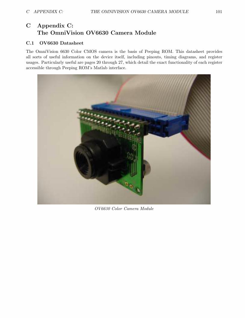
C APPENDIX C: THE OMNIVISION OV6630 CAMERA MODULE 101
C Appendix C:The OmniVision OV6630 Camera Module
C.1 OV6630 Datasheet
The OmniVision 6630 Color CMOS camera is the basis of Peeping ROM. This datasheet providesall sorts of useful information on the device itself, including pinouts, timing diagrams, and registerusages. Particularly useful are pages 20 through 27, which detail the exact functionality of each registeraccessible through Peeping ROM’s Matlab interface.
OV6630 Color Camera Module
Related Documents