ANNIVERSARY CATALOGUE 2020

Welcome message from author
This document is posted to help you gain knowledge. Please leave a comment to let me know what you think about it! Share it to your friends and learn new things together.
Transcript

ANNIVERSARY
CATALOGUE 2020

MAXIJET AUSTRALIA PTY LTD
32 McGregors DriveKeilor Park Vic 3042
tel. 1800 MAXIJET tel. +61 03 9336 1000
fax +61 03 9336 1099
Follow us on:
NATIONAL HEAD OFFICE

NKUP
Multi-stage submersible pumps
5862
TOP MULTI-TECH
Multi-stage submersible pumps
54
72
TEX
Submersible pumps "VORTEX"
90 PLUG & DRAIN 148
DG PED
Pressurisation system with inverter
52
TISSEL-200
Pumps with inverter
42
FLUID SOLAR
Solar pumps
76
PK
Peripheral pumps
4
CPHF
Centrifugal pumps
818
2-7CR
Multi-stage centrifugal pumps
34
JSW – SPRINKLER
Self-priming centrifugal pumps
26
JCR – PLURIJET
Self-priming centrifugal pumps
22
CONTENTS
LTI
submersible pum
venting ods
elf priming centriffugal pumps fug
TOP MULTI-AD
Submersible pumps for AdBlue®
86pumps for AdBlue®
RX
Stainless steel submersible pumps
98
ZX2
Submersible pumps
110
BC-STBC
Submersible pumps
114120
VX
Submersible pumps
126
D
Submersible pumps
132
MC
Submersible pumps
136
SAR40 - 100
Accumulation and lifting stations
140
ation and lifting stations
EASYPRESS
Pressure conrollers
150
82
TOP MULTI 66
4BLOCK
4" monoblock submersible pumpsblock submersible
TOP
Submersible pumps

14
PK
PERFORMANCE RANGE • Flow rate up to 90 l/min (5.4 m³/h) • Head up to 100 m
APPLICATION LIMITS • Manometric suction lift up to 8 m • Liquid temperature between -10 °C and +60 °C • Ambient temperature up to +40 °C (+50 °C for PK 60) • Max. working pressure:
– 6 bar for PK 60, PK 60-MD, PK 65, – 7 bar for PK 70, PK 80 – 10 bar for PK 90, PK 100, PK 200, PK 300
• Continuous service S1
CONSTRUCTION AND SAFETY STANDARDSEN 60335-1IEC 60335-1CEI 61-150
EN 60034-1IEC 60034-1CEI 2-3
CERTIFICATIONS
ISO 9001: QUALITY
INSTALLATION AND USESuitable for use with clean water that does not contain abrasive particles and with liquids that are not chemically aggressive towards the materials from which the pump is made.Because of their reliability and the fact that they are easy to use and are economical, they are ideal for domestic use and in particular for distributing water in combination with small pressure tanks and for the irrigation of gardens and orchards.Installation needs to be undertaken in well ventilated closed areas or anyway protected from bad weather.
PATENTS - TRADE MARKS - MODELS • Motor bracket: patent n. IT1243605 • Shaft: patent n. 0000275945 (PK60, PK65) • Pump body: patent n. 0000275946 (PK60, PK65) • Registered EU Design n. 004673192
• PKm 60® Registered Trade Mark n. 009875394
OPTIONS AVAILABLE ON REQUEST • Special mechanical seal • Other voltages or 60 Hz frequency • IP X5 class protection for PK 70-80-90-100-200-300
Clean water
Domestic use
Pumps with peripheral impeller
50 Hz | PK 4
15
0 5 10 15 20 25 30 35 40 45 50 55 60 65 70 75 80 85 900
10
20
30
40
50
60
70
80
90
100
0
50
100
150
200
250
300
0 5 10 15 20
0 5 10 15
0 1 2 3 4 5
US g.p.m.
Imp g.p.m.feet
l/minm³/h
PK300
PK200PK90
PK100
PK80PK70
PK65
PK60
PK60-MD
Flow rate Q
Hea
d H
(m
etre
s)
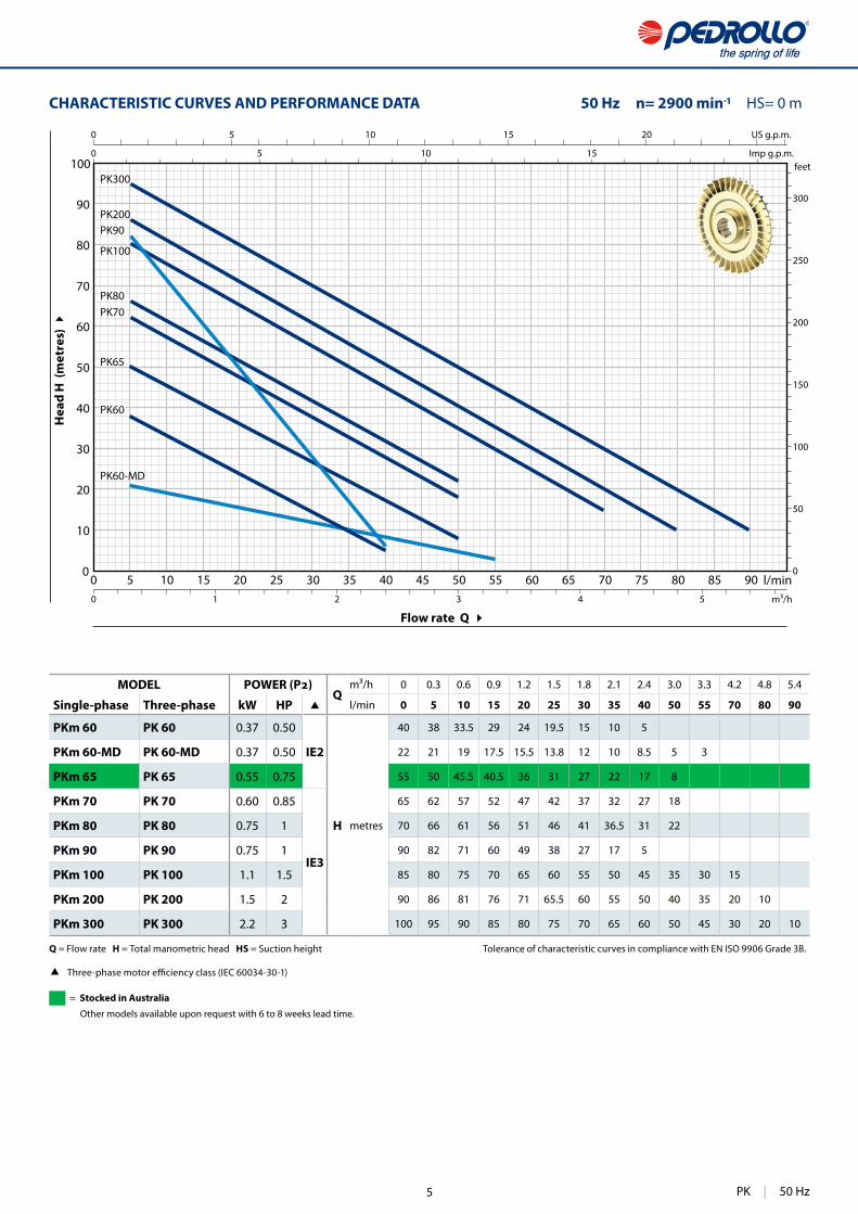
CHARACTERISTIC CURVES AND PERFORMANCE DATA 50 Hz n= 2900 min HS= 0 m
MODELQ
m³/h 0 0.3 0.6 0.9 1.2 1.5 1.8 2.1 2.4 3.0 3.3 4.2 4.8 5.4
Single-phase Three-phase kW HP l/min 0 5 10 15 20 25 30 35 40 50 55 70 80 90
PKm 60 PK 60 0.37 0.50
IE2
H metres
40 38 33.5 29 24 19.5 15 10 5
PKm 60-MD PK 60-MD 0.37 0.50 22 21 19 17.5 15.5 13.8 12 10 8.5 5 3
PKm 70 PK 70 0.60 0.85
IE3
65 62 57 52 47 42 37 32 27 18
PKm 80 PK 80 0.75 1 70 66 61 56 51 46 41 36.5 31 22
PKm 90 PK 90 0.75 1 90 82 71 60 49 38 27 17 5
PKm 100 PK 100 1.1 1.5 85 80 75 70 65 60 55 50 45 35 30 15
PKm 200 PK 200 1.5 2 90 86 81 76 71 65.5 60 55 50 40 35 20 10
PKm 300 PK 300 2.2 3 100 95 90 85 80 75 70 65 60 50 45 30 20 10
Q = Flow rate H = Total manometric head HS = Suction height Tolerance of characteristic curves in compliance with EN ISO 9906 Grade 3B.
(IEC 60034-30-1)
PK | 50 Hz
PKm 65 PK 65 0.55 0.75 55 50 45.5 40.5 36 31 27 22 17 8
= Stocked in Australia
Other models available upon request with 6 to 8 weeks lead time.
5

16
PK
6 67
1 3 5 2 4 8
POS. COMPONENT CONSTRUCTION CHARACTERISTICS
1 PUMP BODY Cast iron, with threaded ports in compliance with ISO 228/1 (PK 60, PK 60-MD with an Epoxy Electro Coating treatment)
2 MOTOR BRACKET Aluminium with brass insert (patented), reduces the risk of impeller seizure
3 IMPELLER Brass with peripheral radial vanes
4 MOTOR SHAFT Stainless steel AISI 431 (EN 10088-3 - 1.4104 for PK 60, PK 60-MD, PK 65)
5 MECHANICAL SEAL Pump Seal Shaft MaterialsModel Model Diameter Stationary ring Rotational ring Elastomer
PK 60-65-70-80PK 60-MD AR-12 Ø 12 mm Ceramic Graphite NBR
PK 90 ST1-12 Ø 12 mm Silicon carbide Graphite NBRPK 100-200-300 FN-14 Ø 14 mm Graphite Ceramic NBR
6 BEARINGS Pump Model
PK 60-65PK 60-MD 6201 ZZ / 6201 ZZ
PK 70-80-90 6203 ZZ / 6203 ZZPK 100-200-300 6204 ZZ / 6204 ZZ
7 CAPACITOR Pump CapacitanceSingle-phase (230 V or 240 V) (110 V)
PKm 60 PKm 60-MD 10 25
PKm 70 16 60 PKm 80 20 60 PKm 90 20 60 PKm 100 31.5 60 PKm 200 45 80 PKm 300 50 –
8 ELECTRIC MOTOR PKm: single-phase 230 V - 50 Hz with thermal overload protector incorporated into the winding.PK: three-phase 230/400 V - 50 Hz.
➠ The three-phase pumps are �tted with high performance motors up to
– Insulation: class F – Protection: IP X4
50 Hz | PK
PKm 65 14 25 450 250
6

17
f
DN2D
N1
a w ms
i
tn2
h3h2
h1
h
DIMENSIONS AND WEIGHT
MODEL PORTS DIMENSIONS mm kg
Single-phase Three-phase DN1 DN2 a f h h1 h2 h3 i m t n2 w s 1~ 3~
PKm 60® PK 60®
1" 1"
38208 145 56
75131
20
55 118 94-10053
7
5.2 5.2
PKm 60®-MD PK 60®-MD 5.2 5.2
PKm 65 PK 65 237 153 63 138 80 120 100 7.0 6.3
PKm 70 PK 7055 285
179 * 7185 156
90 140 112 62
10.0 10.0
PKm 80 PK 80 9.9 10.0
PKm 90 PK 90 ¾" ¾" 46 278 84 155 19 10.2 10.1
PKm 100 PK 100
1" 1" 62356
212 80 88 168 19 100 152 125 95 9
15.0 14.9
PKm 200 PK 200 15.9 15.9
PKm 300 PK 300 376 — 18.6
ABSORPTION
MODEL VOLTAGE
Single-phase 230 V 240 V 110 V
PKm 60® 2.5 A 2.4 A 5.5 APKm 60®-MD 2.0 A 1.9 A 4.0 A PKm 65 3.7 A 3.4 A 7.4 A
PKm 70 5.2 A 4.8 A 10.4 A
PKm 80 5.2 A 4.8 A 10.4 A
PKm 90 5.6 A 5.1 A 11.5 A
PKm 100 9.0 A 8.2 A 18.0 A
PKm 200 11.5 A 11.0 A 23.0 A
PKm 300 — — —
MODEL VOLTAGE
Three-phase 230 V 400 V 690 V 240 V 415 V
PK 60® 2.0 A 1.15 A 0.7 A 1.9 A 1.1 A
PK 60®-MD 1.7 A 1.0 A 0.6 A 1.7 A 1.0 A
PK 65 3.0 A 1.7 A 1.0 A 2.8 A 1.6 A
PK 70 3.8 A 2.2 A 1.3 A 3.3 A 1.9 A
PK 80 3.8 A 2.2 A 1.3 A 3.3 A 1.9 A
PK 90 4.0 A 2.3 A 1.3 A 3.8 A 2.2 A
PK 100 6.2 A 3.6 A 2.1 A 5.9 A 3.4 A
PK 200 8.3 A 4.8 A 2.8 A 8.0 A 4.6 A
PK 300 9.0 A 5.2 A 3.0 A 8.7 A 5.0 A
MODEL GROUPAGE CONTAINER
Single-phase Three-phase n. pumps n. pumps
PKm 60® PK 60® 240 330
PKm 60®-MD PK 60®-MD 240 330
PKm 65 PK 65 189 243
PKm 70 PK 70 102 170
PKm 80 PK 80 102 170
PKm 90 PK 90 102 170
PKm 100 PK 100 72 96
PKm 200 PK 200 72 96
PKm 300 PK 300 72 96
PALLETIZATION
(*) h=199 mm for single-phase versions at 110 V
PK | 50 Hz7

38
CP
INSTALLATION AND USESuitable for use with clean water and with liquids that are not chemically aggressive towards the materials from which the pump is made. As a result of their reliability and the fact that they are easy to use, these pumps are widely used in civil, agricultural and industrial applications such as for supplying water, in air conditioning and cooling systems, for irrigation, etc.Installation needs to be undertaken in well ventilated closed areas or anyway protected from bad weather.
PATENTS - TRADE MARKS - MODELS • Registered EU Design n. 002098434 for CP 160, CP210, CP250 • Registered Italian model n. 72753 for CP 220, CP 230
OPTIONS AVAILABLE ON REQUEST • Special mechanical seal • EN 10088-3 - 1.4401 (AISI 316) stainless steel pump shaft
for CP 220, CP 230, CP250 • Other voltages or 60 Hz frequency • IP X5 class protection for CP 160
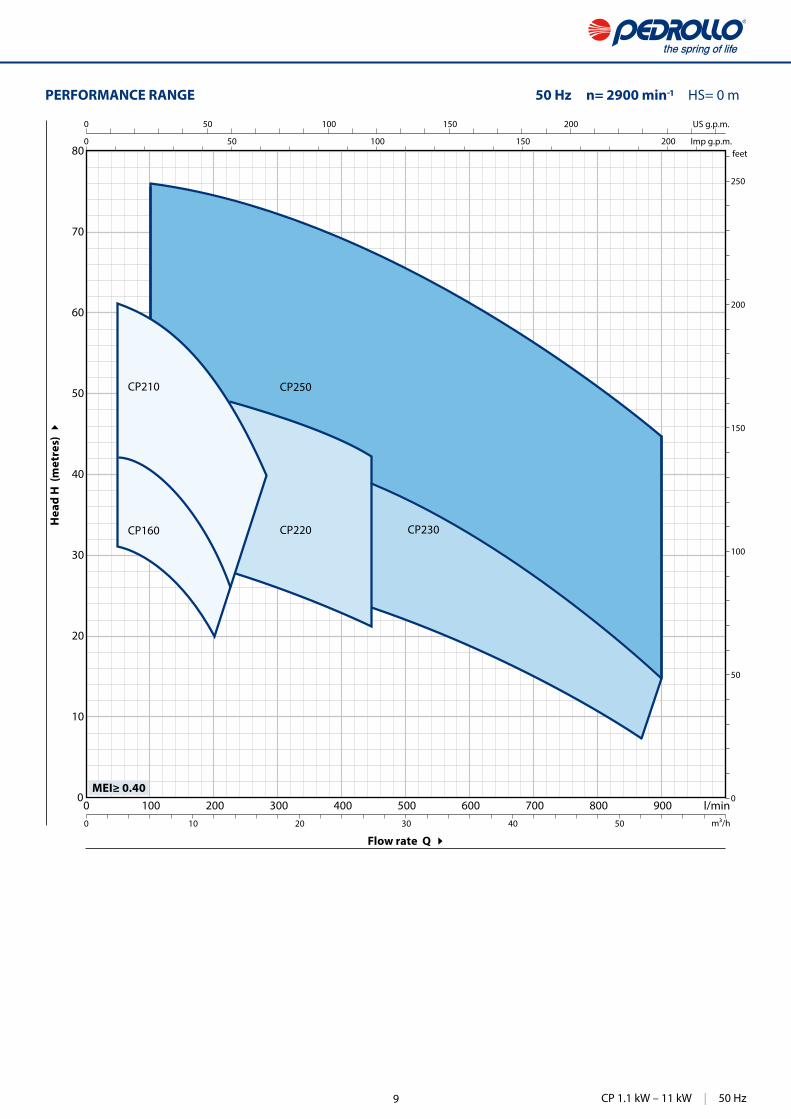
PERFORMANCE RANGE • Flow rate up to 900 l/min (54 m³/h) • Head up to 76 m
APPLICATION LIMITS • Manometric suction lift up to 7 m • Liquid temperature between -10 °C and +90 °C • Ambient temperature between -10 °C and +40 °C • Max. working pressure 10 bar • Continuous service S1
CONSTRUCTION AND SAFETY STANDARDSEN 60335-1IEC 60335-1CEI 61-150
EN 60034-1IEC 60034-1CEI 2-3
EU REGULATION N. 547/2012
CERTIFICATIONS
ISO 9001: QUALITY
Centrifugal pumpsClean water
Civil use
Industrial use
Agricultural use
50 Hz | CP 1.1 kW – 11 kW 8
39
0 100 200 300 400 500 600 700 800 9000
10
20
30
40
50
60
70
80
0
50
100
150
200
250
0 50 100 150 200
0 50 100 150 200
0 10 20 30 40 50
CP220 CP230
CP250
US g.p.m.
Imp g.p.m.feet
l/minm³/h
CP210
CP160
MEI≥ 0.40
Flow rate Q
Hea
d H
(m
etre
s)
PERFORMANCE RANGE 50 Hz n= 2900 min HS= 0 m
CP 1.1 kW – 11 kW | 50 Hz9

40
CP 160-210
0 50 100 150 200 2500
1
2
3
40
1
2
3
4
10
20
30
40
50
60
70
50
100
150
200
0
1
2
3
4
5
0 10 20 30 40 50 60 70
0 10 20 30 40 50 60
0 5 10 15
0
2
4
6
8
10
12
14
η = 57%
50
4246
4849
50
51
51
50
54
56
56
η =
US g.p.m.
Imp g.p.m.feet
l/min
m³/h
CP210A
CP210A
CP210
CP210B
CP210B
CP210C
CP210C
CP160A
CP160A
CP160B
CP160B
CP160
CP160C
CP160C
MEI≥ 0.40
Hea
d H
(m
etre
s)
NPS
H (
met
res)
A
bsor
bed
pow
er
(kW
)
(H
P)N
PSH
(fe
et)
H (
feet
)
Flow rate Q
CHARACTERISTIC CURVES AND PERFORMANCE DATA 50 Hz n= 2900 min HS= 0 m
Q = Flow rate H = Total manometric head HS = Suction height Tolerance of characteristic curves in compliance with EN ISO 9906 Grade 3B.
IEC 60034-30-1)
MODELQ
m³/h 0 3 4.5 6 7.5 9 10.5 12 13.2 14.4 15 16.2 16.8
Single-phase Three-phase kW HP l/min 0 50 75 100 125 150 175 200 220 240 250 270 280
CPm 160C CP 160C 1.1 1.5
IE3 H metres
32 31 30.5 29.5 28 26 23 20
CPm 160B CP 160B 1.5 2 37 36 35.5 34.5 33.5 31.5 29 26.5 23
– CP 160A 2.2 3 43 42 41.5 40.5 39.5 38 35.5 33 30 26
CPm 210C CP 210C 2.2 3 46 45.5 44.5 43.5 42 40 37.5 34.5 32 28.5 27
– CP 210B 3 4 54 53 52 51 49.5 48 45.5 43 40 38.5 37 34
– CP 210A 4 5.5 61 61 60 59 57.5 56 53.5 51 49 46.5 45 42 40
50 Hz | CP 160-210
= Stocked in Australia
Other models available upon request with 6 to 8 weeks lead time.
10
41
η
59
CP220A
CP220B
CP220C
CP220AH
AHA
B
C
CP 220
MEI≥ 0.40
Hea
d H
(m
etre
s)
NPS
H (
met
res)
Abs
orbe
d po
wer
(
kW)
(HP)
NPS
H (
feet
) H
(fe
et)
Flow rate Q
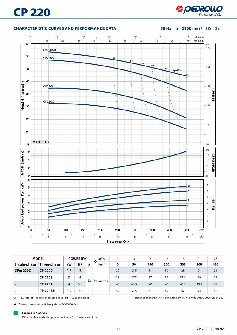
CHARACTERISTIC CURVES AND PERFORMANCE DATA 50 Hz n= 2900 min HS= 0 m
MODELQ
m³/h 0 3 6 12 18 24 27
Single-phase Three-phase kW HP l/min 0 50 100 200 300 400 450
CPm 220C CP 220C 2.2 3
IE3 H metres
32 31.5 31 30 28 24 21
– CP 220B 3 4 38 37.5 37 36 33.5 29 25
– CP 220A 4 5.5 49 48.5 48 46 43.5 39.5 36
– CP 220AH 5.5 7.5 52 51.5 51 49 47 44 42
Q = Flow rate H = Total manometric head HS = Suction height Tolerance of characteristic curves in compliance with EN ISO 9906 Grade 3B.
IEC 60034-30-1)
CP 220 | 50 Hz
= Stocked in Australia
Other models available upon request with 6 to 8 weeks lead time.
11

42
η = 65%
64
64
CP230A
CP230B
CP230C
AB
C
C A-B
CP 230
MEI≥ 0.40
Hea
d H
(m
etre
s)
NPS
H (
met
res)
A
bsor
bed
pow
er
(kW
)
(H
P)N
PSH
(fe
et)
H (
feet
)
Flow rate Q
CHARACTERISTIC CURVES AND PERFORMANCE DATA 50 Hz n= 2900 min HS= 0 m
MODELQ
m³/h 0 6 12 18 24 30 36 42 48 51 54
Three-phase kW HP l/min 0 100 200 300 400 500 600 700 800 850 900
CP 230C 3 4
IE3 H metres
30 29.5 28.5 27 25 22 19.5 15.5 11.5 9
CP 230B 4 5.5 39 38.5 38 36 34 31 28 24 18.5 15 13
CP 230A 5.5 7.5 46 45.5 44.5 42 40 37 32.5 27.5 21.5 18 15
Q = Flow rate H = Total manometric head HS = Suction height Tolerance of characteristic curves in compliance with EN ISO 9906 Grade 3B.
IEC 60034-30-1)
50 Hz | CP 230
= Stocked in Australia
Other models available upon request with 6 to 8 weeks lead time.
12
43
0 100 200 300 400 500 600 700 800 9000
2
4
6
8
10
12
140
2
4
6
8
1020
30
40
50
60
70
80
90
75
100
125
150
175
200
225
250
275
0
4
8
12
16
0 20 40 60 80 100 120 140 160 180 200 220 240
0 20 40 60 80 100 120 140 160 180 200
0 5 10 15 20 25 30 35 40 45 50 55
0
4
8
12
16
20
US g.p.m.
Imp g.p.m.feet
l/min
m³/h
5045
55
55
58
58
η = 60%
CP250A
CP250B
A
B
CP 250
MEI≥ 0.40
Hea
d H
(m
etre
s)
NPS
H (
met
res)
Abs
orbe
d po
wer
(
kW)
(HP)
NPS
H (
feet
) H
(fe
et)
Flow rate Q
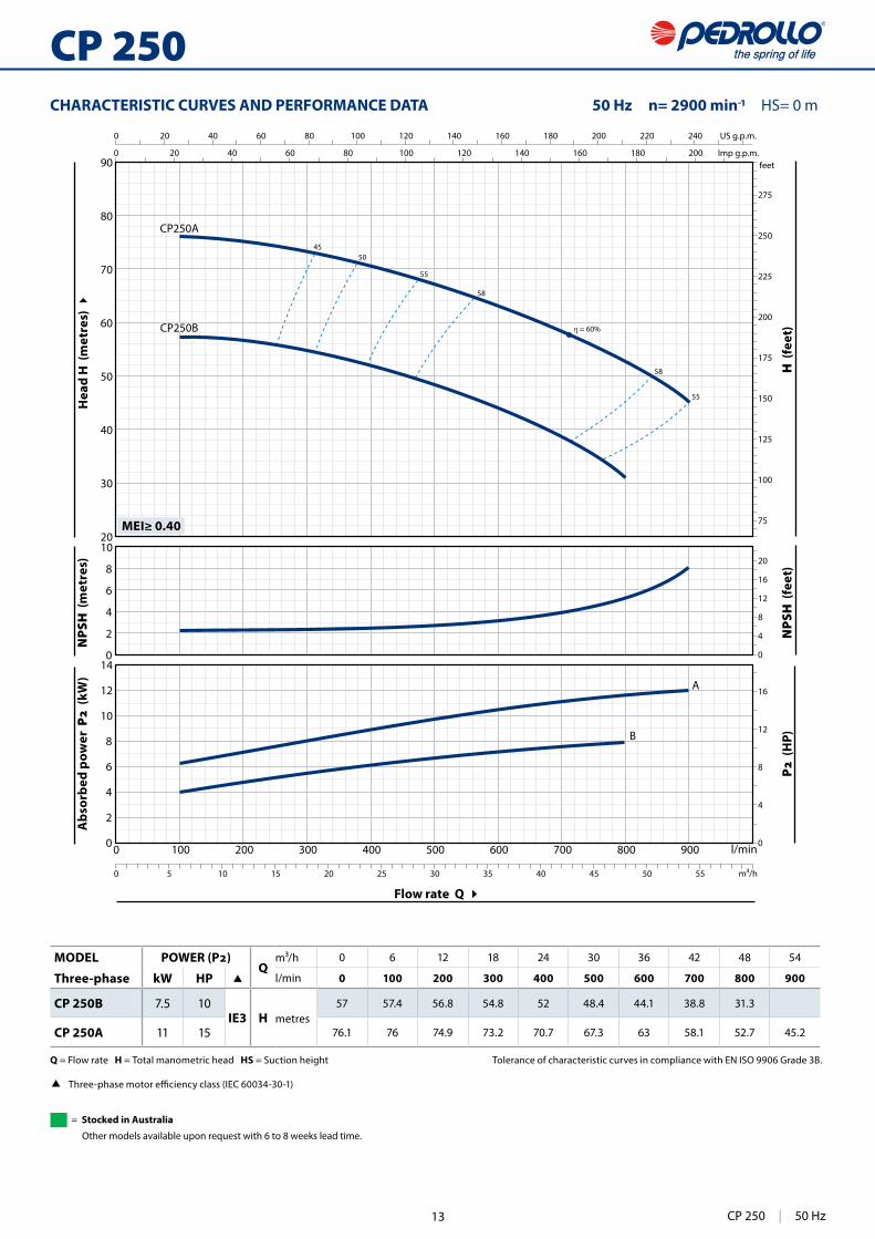
CHARACTERISTIC CURVES AND PERFORMANCE DATA 50 Hz n= 2900 min HS= 0 m
MODELQ
m³/h 0 6 12 18 24 30 36 42 48 54
Three-phase kW HP l/min 0 100 200 300 400 500 600 700 800 900
CP 250B 7.5 10IE3 H metres
57 57.4 56.8 54.8 52 48.4 44.1 38.8 31.3
CP 250A 11 15 76.1 76 74.9 73.2 70.7 67.3 63 58.1 52.7 45.2
Q = Flow rate H = Total manometric head HS = Suction height Tolerance of characteristic curves in compliance with EN ISO 9906 Grade 3B.
IEC 60034-30-1)
CP 250 | 50 Hz
= Stocked in Australia
Other models available upon request with 6 to 8 weeks lead time.
13
44
CP 160-210
1 3 2 5 4 8
66 7
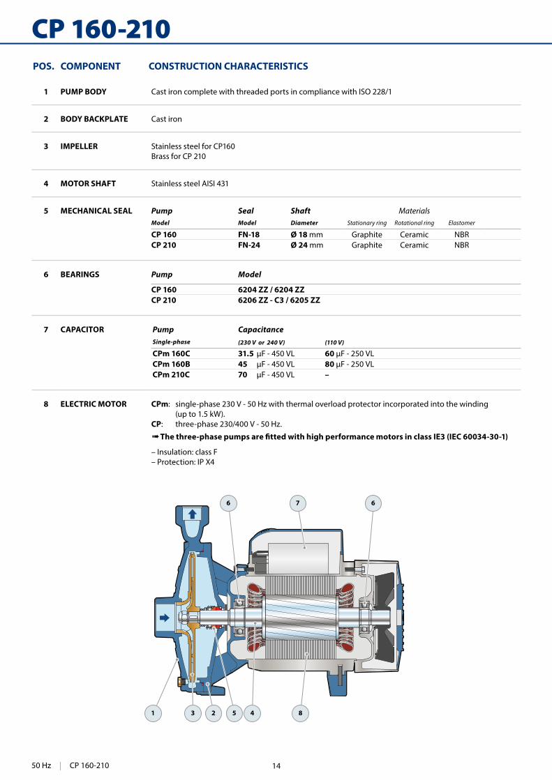
POS. COMPONENT CONSTRUCTION CHARACTERISTICS
1 PUMP BODY Cast iron complete with threaded ports in compliance with ISO 228/1
2 BODY BACKPLATE Cast iron
3 IMPELLER Stainless steel for CP160Brass for CP 210
4 MOTOR SHAFT Stainless steel AISI 431
5 MECHANICAL SEAL Pump Seal Shaft MaterialsModel Model Diameter Stationary ring Rotational ring Elastomer
CP 160 FN-18 Ø 18 mm Graphite Ceramic NBRCP 210 FN-24 Ø 24 mm Graphite Ceramic NBR
6 BEARINGS Pump Model
CP 160 6204 ZZ / 6204 ZZCP 210 6206 ZZ - C3 / 6205 ZZ
7 CAPACITOR Pump CapacitanceSingle-phase (230 V or 240 V) (110 V)
CPm 160C 31.5 60 CPm 160B 45 80 CPm 210C 70 –
8 ELECTRIC MOTOR CPm: single-phase 230 V - 50 Hz with thermal overload protector incorporated into the winding (up to 1.5 kW).CP: three-phase 230/400 V - 50 Hz.
➠ The three-phase pumps are �tted with high performance motors in class IE3 (IEC 60034-30-1)
– Insulation: class F – Protection: IP X4
50 Hz | CP 160-210 14

45
f
aDN2
DN
1
n1
n2
h3
h2h1
sw
DIMENSIONS AND WEIGHT
ABSORPTION
MODEL VOLTAGE
Three-phase 230 V 400 V 690 V 240 V 415 V 720 V
CP 160C 5.7 A 3.3 A 1.9 A 5.5 A 3.2 A 1.8 A
CP 160B 6.9 A 4.0 A 2.3 A 6.7 A 3.8 A 2.2 A
CP 160A 8.9 A 5.1 A 2.9 A 8.3 A 4.8 A 2.8 A
CP 210C 9.2 A 5.3 A 3.1 A 8.8 A 5.1 A 2.9 A
CP 210B 11.2 A 6.5 A 3.8 A 10.8 A 6.2 A 3.6 A
CP 210A 14.8 A 8.5 A 4.9 A 14.2 A 8.2 A 4.7 A
MODEL VOLTAGE
Single-phase 230 V 240 V 110 V
CPm 160C 8.5 A 8.2 A 17.0 A
CPm 160B 10.3 A 10.0 A 20.6 A
CPm 210C 14.5 A 12.7 A 29.0 A
MODEL PORTS DIMENSIONS mm kg
Single-phase Three-phase DN1 DN2 a f h1 h2 h3 n1 n2 w s 1~ 3~
CPm 160C CP 160C
1½" 1"
54370
110 150 260 206 165 44.5 11
19.3 18.8
CPm 160B CP 160B 20.0 20.5
– CP 160A 391 – 23.5
CPm 210C CP 210C
60 402 125 180 305 252 210 39.5 11
29.0 29.2
– CP 210B – 31.0
– CP 210A – 31.2
CP 160-210 | 50 Hz15

46
CP 220-230-250
1 3 2 5 4 8
66 7
POS. COMPONENT CONSTRUCTION CHARACTERISTICS
1 PUMP BODY Cast iron complete with threaded ports in compliance with ISO 228/1
2 BODY BACKPLATE Cast iron
3 IMPELLER Brass for CP 220, CP 230 Cast iron for CP 250
4 MOTOR SHAFT Stainless steel AISI 431
5 MECHANICAL SEAL Pump Seal Shaft MaterialsModel Model Diameter Stationary ring Rotational ring Elastomer
CP 220C-BCP 230C FN-20 Ø 20 mm Graphite Ceramic NBR
CP 220A-AHCP 230B-ACP 250B
FN-24 Ø 24 mm Graphite Ceramic NBR
CP 250A FN-32 NU Ø 32 mm Graphite Ceramic NBR
6 BEARINGS Pump Model
CP 220C 6206 ZZ - C3 / 6204 ZZCPm 220CCP 220BCP 230C
6206 ZZ - C3 / 6205 ZZ
CP 220A-AHCP 230B-ACP 250B
6307 ZZ - C3 / 6206 ZZ - C3
CP 250A 6310 ZZ - C3 / 6308 ZZ - C3
7 CAPACITOR Pump CapacitanceSingle-phase (230 V or 240 V)
CPm 220C 70
8 ELECTRIC MOTOR CPm: single-phase 230 V - 50 Hz.CP: three-phase 230/400 V - 50 Hz up to 4 kW. 400/690 V - 50 Hz from 5.5 to 11 kW.
➠ The three-phase pumps are �tted with high performance motors in class IE3 (IEC 60034-30-1)– Insulation: class F – Protection: IP X5
50 Hz | CP 220-230-250 16

47
w
f
a
n2
h2h1
h3
n1
t
DN2
DN
1
s
DIMENSIONS AND WEIGHT
ABSORPTION
MODEL VOLTAGE
Three-phase 230 V 400 V 690 V 240 V 415 V 720 V
CP 220C 11.4 A 6.6 A 3.8 A 10.7 A 6.2 A 3.6 A
CP 220B 12.6 A 7.3 A 4.2 A 12.0 A 7.0 A 4.0 A
CP 220A 17.0 A 9.8 A 5.7 A 16.5 A 9.5 A 5.5 A
CP 220AH 20.0 A 11.5A 6.7 A 19.2 A 11.0 A 6.4 A
CP 230C 13.2 A 7.6 A 4.4 A 12.8 A 7.4 A 4.2 A
CP 230B 16.8 A 9.7 A 5.6 A 16.2 A 9.4 A 5.4A
CP 230A 20.0 A 11.5A 6.7 A 19.2 A 11.0 A 6.4 A
CP 250B 25.9 A 15.0 A 8.7 A 25.0 A 14.5 A 8.4 A
CP 250A 39.0 A 22.5 A 13.0 A 38.9 A 22.5 A 13.0 A
MODEL VOLTAGE
Single-phase 230 V 240 V
CPm 220C 15.8 A 15.0 A
MODEL PORTS DIMENSIONS mm kg
Single-phase Three-phase DN1 DN2 a f h1 h2 h3 t n1 n2 w s 1~ 3~
CPm 220C CP 220C
2" 2"
70
440/429132 183 315 243 230 170
40
14
34.1 32.8
– CP 220B 441 – 36.2
– CP 220A 459136 192 328 273 250 190
– 41.0
– CP 220AH 505 – 47.8
– CP 230C 440 132 183 315 243 230 170 – 31.9
– CP 230B 460136 192 328 273 250 190
– 41.0
– CP 230A 505 – 46.0
– CP 250B65
506160 232 392 317 294 230 45
– 74.0
– CP 250A 570 – 103.0
CP 220-230-250 | 50 Hz17
150
HF
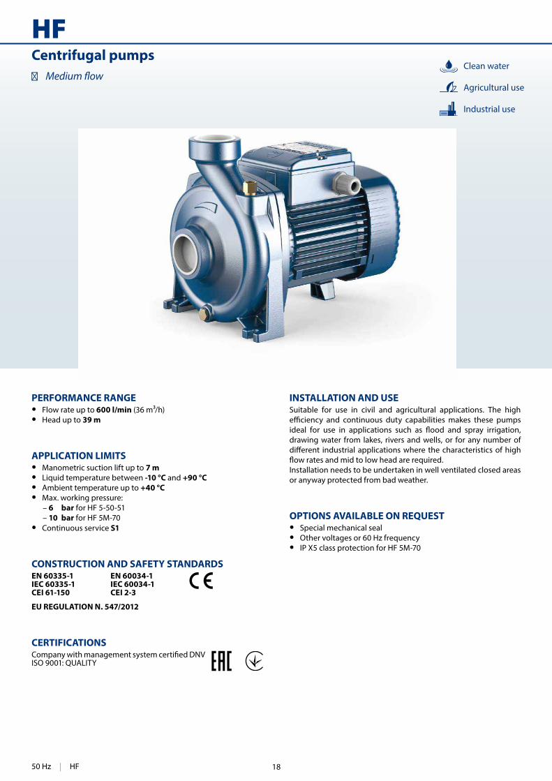
INSTALLATION AND USESuitable for use in civil and agricultural applications. The high
drawing water from lakes, rivers and wells, or for any number of
Installation needs to be undertaken in well ventilated closed areas or anyway protected from bad weather.
OPTIONS AVAILABLE ON REQUEST • Special mechanical seal • Other voltages or 60 Hz frequency • IP X5 class protection for HF 5M-70
PERFORMANCE RANGE • Flow rate up to 600 l/min (36 m³/h) • Head up to 39 m
APPLICATION LIMITS • Manometric suction lift up to 7 m • Liquid temperature between -10 °C and +90 °C • Ambient temperature up to +40 °C • Max. working pressure:
– 6 bar for HF 5-50-51 – 10 bar for HF 5M-70 • Continuous service S1
CONSTRUCTION AND SAFETY STANDARDSEN 60335-1IEC 60335-1CEI 61-150
EN 60034-1IEC 60034-1CEI 2-3
EU REGULATION N. 547/2012
CERTIFICATIONS
ISO 9001: QUALITY
Centrifugal pumps�
Clean water
Industrial use
Agricultural use
50 Hz | HF 18

151
0 50 100 150 200 250 300 350 400 450 500 550 6000
5
10
15
20
25
30
35
40
0
25
50
75
100
125
0 50 100 150
0 50 100
0 5 10 15 20 25 30 35
HF70A
HF70B
HF70C
HF51AHF5AM
HF5BMHF51B
HF50A
HF50B
HF5CHF5BHF5A
η = 60%
η = 63%
η = 67%
η = 72%
η = 74%
US g.p.m.
Imp g.p.m.feet
l/minm³/h
MEI≥ 0.40
CHARACTERISTIC CURVES AND PERFORMANCE DATA 50 Hz n= 2900 min HS= 0 m
Flow rate Q
Hea
d H
(m
etre
s)
Q =Flow rate H =Total manometric head HS = Suction height Tolerance of characteristic curves in compliance with EN ISO 9906 Grade 3B.
MODELQ
m³/h 0 3 6 9 12 15 18 21 24 30 36
Single-phase Three-phase kW HP l/min 0 50 100 150 200 250 300 350 400 500 600
HFm 50B HF 50B 0.37 0.50IE2
H metres
10 10 9.5 8.5 7.5 6 4
HFm 50A HF 50A 0.55 0.75 12 12 11.5 11 9.6 8 6
HFm 51B HF 51B 0.55 0.75
IE3
18.2 17.2 16 14 11.5 9 5.4
HFm 51A HF 51A 0.75 1 21.2 20.2 19 17 14.5 11.6 8.4
HFm 70C HF 70C 1.1 1.5 29 28 26.5 24.5 22 18.5 15
HFm 70B HF 70B 1.5 2 33 32 30.5 28.5 26 22.5 19
– HF 70A 2.2 3 39 38 36.5 34.5 32 28.5 25
HFm 5C HF 5C 0.55 0.75 IE2 12.5 – 12 11.7 11 10.2 9.2 8 6.5
HFm 5B HF 5B 0.75 1
IE3
13.7 – 13.2 13 12.5 11.6 10.5 9.2 8 5
HFm 5A HF 5A 1.1 1.5 14.5 – 13.8 13.5 13.2 12.6 11.8 10.5 9.2 6.5 3
HFm 5BM HF 5BM 1.1 1.5 19 – 18.5 18 17 16 15.2 14 12.8 9.7 6
HFm 5AM HF 5AM 1.5 2 22 – 21.5 21 20.5 19.8 19 18 16.8 13.8 10
HF | 50 Hz
= Stocked in Australia
Other models available upon request with 6 to 8 weeks lead time.
19

152
HF
6 7 6
4 8531
2
POS. COMPONENT CONSTRUCTION CHARACTERISTICS
1 PUMP BODY Cast iron complete with threaded ports in compliance with ISO 228/1
2 BODY BACKPLATE Stainless steel AISI 304 (cast iron for HF 5M-70)
3 IMPELLER Brass
4 MOTOR SHAFT Stainless steel AISI 431
5 MECHANICAL SEAL Pump Seal Shaft MaterialsModel Model Diameter Stationary ring Rotational ring Elastomer
HF 50 AR-12 Ø 12 mm Ceramic Graphite NBRHF 5-51 AR-14 Ø 14 mm Ceramic Graphite NBRHF 5M-70 FN-18 Ø 18 mm Graphite Ceramic NBR
6 BEARINGS Pump Model
HF 50 6201 ZZ / 6201 ZZHF 5-51 6203 ZZ / 6203 ZZHF 5M-70 6204 ZZ / 6204 ZZ
7 CAPACITOR Pump CapacitanceSingle-phase (230 V or 240 V) (110 V)
HFm 50B 10 25HFm 50A 14 25HFm 51B 20 60HFm 51A 20 60HFm 70C 25 60HFm 70B 45 80HFm 5C 16 60HFm 5B 20 60HFm 5A 25 60HFm 5BM 25 60HFm 5AM 45 80
8 ELECTRIC MOTOR HFm: single-phase 230 V - 50 Hz with thermal overload protector incorporated into the winding.HF: three-phase 230/400 V - 50 Hz.
➠ The three-phase pumps are �tted with high performance motors up to
– Insulation: class F – Protection: IP X4
50 Hz | HF 20

153
f t
a
DN2
w
DN
1
h2
n2
h1
h3
s
DIMENSIONS AND WEIGHT
ABSORPTION
MODEL VOLTAGE
Three-phase 230 V 400 V 690 V 240 V 415 V 720 V
HF 50B 2.1 A 1.2 A 0.7 A 2.1 A 1.2 A 0.7 A
HF 50A 3.0 A 1.7 A 1.0 A 2.8 A 1.6 A 0.9 A
HF 51B 3.6 A 2.1 A 1.2 A 3.5 A 2.0 A 1.2 A
HF 51A 4.4 A 2.5 A 1.2 A 4.0 A 2.3 A 1.4 A
HF 70C 6.1 A 3.3 A 2.0 A 5.5 A 3.2 A 1.9 A
HF 70B 7.4 A 4.3 A 2.5 A 7.1 A 4.1 A 2.4 A
HF 70A 9.5 A 5.5 A 3.2 A 9.1 A 5.3 A 3.0 A
HF 5C 3.5 A 2.0 A 1.2 A 3.3 A 1.9 A 1.1 A
HF 5B 3.6 A 2.1 A 1.2 A 3.5 A 2.0 A 1.2 A
HF 5A 5.0 A 2.9 A 1.7 A 3.6 A 2.1 A 1.6 A
HF 5BM 5.7 A 3.3 A 1.9 A 5.5 A 3.2 A 1.8 A
HF 5AM 7.1 A 4.1 A 2.4 A 6.5 A 3.7 A 2.3 A
MODEL VOLTAGE
Single-phase 230 V 240 V 110 V
HFm 50B 2.8 A 2.6 A 5.6 A
HFm 50A 3.8 A 3.6 A 7.6 A
HFm 51B 4.7 A 4.5 A 9.4 A
HFm 51A 5.6 A 5.3 A 11.2 A
HFm 70C 8.0 A 7.6 A 16.0 A
HFm 70B 10.0 A 9.0 A 20.0 A
HFm 5C 4.2 A 3.8 A 8.4 A
HFm 5B 4.9 A 4.5 A 9.8 A
HFm 5A 6.2 A 5.7 A 12.4 A
HFm 5BM 7.7 A 7.1 A 15.4 A
HFm 5AM 10.1 A 9.7 A 20.2 A
MODEL PORTS DIMENSIONS mm kg
Single-phase Three-phase DN1 DN2 a f h1 h2 h3 t n2 w s 1~ 3~
HFm 50B HF 50B
1½" 1½"
42 270 82 118 200 166 135 -8
10
8.0 8.1
HFm 50A HF 50A 8.9 8.2
HFm 51B HF 51B45 303 92 133 225 190 160 2
12.9 12.7
HFm 51A HF 51A 13.0 13.0
HFm 70C HF 70C
48.5373
114 155 269 216 171 12 12
18.8 20.1
HFm 70B HF 70B 21.4 21.5
– HF 70A 393 – 24.2
HFm 5C HF 5C
2" 2"
43 316 97 141 238 192
160
-68 10
14.3 14.2
HFm 5B HF 5B 14.3 14.3
HFm 5A HF 5A 14.6 14.7
HFm 5BM HF 5BM59 386 110 150 260 208 12.5 11
19.2 20.3
HFm 5AM HF 5AM 21.6 21.6
HF | 50 Hz21
104
JCR1
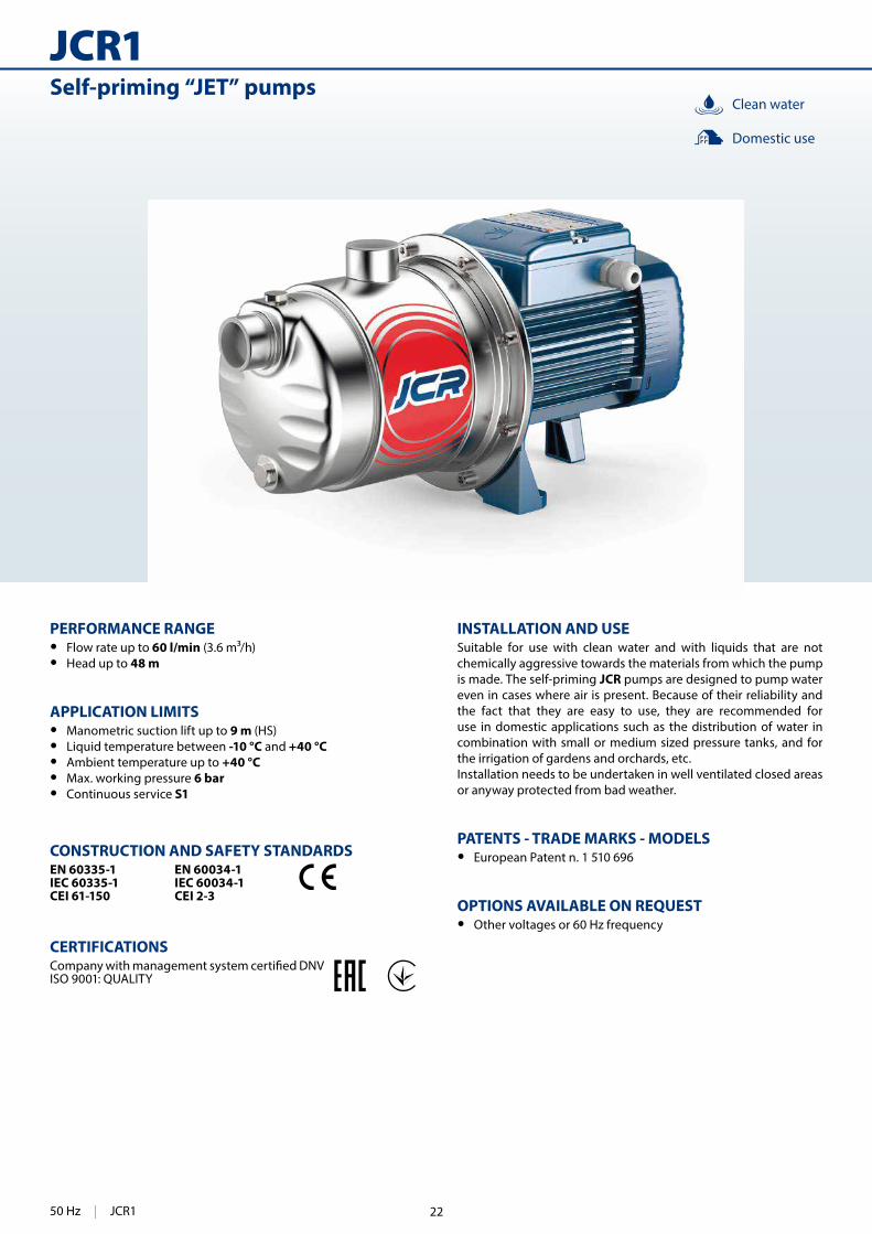
INSTALLATION AND USESuitable for use with clean water and with liquids that are not chemically aggressive towards the materials from which the pump is made. The self-priming JCR pumps are designed to pump water even in cases where air is present. Because of their reliability and the fact that they are easy to use, they are recommended for use in domestic applications such as the distribution of water in combination with small or medium sized pressure tanks, and for the irrigation of gardens and orchards, etc.Installation needs to be undertaken in well ventilated closed areas or anyway protected from bad weather.
PATENTS - TRADE MARKS - MODELS • European Patent n. 1 510 696
OPTIONS AVAILABLE ON REQUEST • Other voltages or 60 Hz frequency
PERFORMANCE RANGE • Flow rate up to 60 l/min (3.6 m³/h) • Head up to 48 m
APPLICATION LIMITS • Manometric suction lift up to 9 m (HS) • Liquid temperature between -10 °C and +40 °C • Ambient temperature up to +40 °C • Max. working pressure 6 bar • Continuous service S1
CONSTRUCTION AND SAFETY STANDARDSEN 60335-1IEC 60335-1CEI 61-150
EN 60034-1IEC 60034-1CEI 2-3
CERTIFICATIONS
ISO 9001: QUALITY
Self-priming “JET” pumpsClean water
Domestic use
50 Hz | JCR1 22

105
0 5 10 15 20 25 30 35 40 45 50 55 605
10
15
20
25
30
35
40
45
50
25
50
75
100
125
150
0 5 10 15
0 5 10
0 0.5 1 1.5 2 2.5 3 3.5
US g.p.m.
Imp g.p.m.feet
l/minm³/h
JCR1A
JCR1B
JCR1C
Flow rate Q
Hea
d H
(m
etre
s)
CHARACTERISTIC CURVES AND PERFORMANCE DATA 50 Hz n= 2900 min HS= 0 m
STANDARD INSTALLATION
HS = Suction height
Non-return valve
MODELQ
m³/h 0 0.3 0.6 1.2 1.5 1.8 2.4 2.7 3.0 3.6
Single-phase Three-phase kW HP l/min 0 5 10 20 25 30 40 45 50 60
JCRm 1 C JCR 1 C 0.37 0.50IE2
H metres
35 32 28.5 23.5 21 18.5 15 13.5 12 10
JCRm 1 B JCR 1 B 0.48 0.65 37 34 30.5 25.5 23 20.5 17 15.5 14 12
JCRm 1 A JCR 1 A 0.55 0.75 IE3 48 43 39 31.5 28.5 26 22 20.5 19 17
Q = Flow rate H = Total manometric head HS = Suction height Tolerance of characteristic curves in compliance with EN ISO 9906 Grade 3B.
JCR1 | 50 Hz
= Stocked in Australia
Other models available upon request with 6 to 8 weeks lead time.
23

106
JCR1
1 43 6 95
772 8
POS. COMPONENT CONSTRUCTION CHARACTERISTICS
1 PUMP BODY Stainless steel AISI 304 complete with threaded ports in compliance with ISO 228/1
2 BODY BACKPLATE Stainless steel AISI 304
3 NOZZLE ASSEMBLY Noryl FE1520PW
4 IMPELLER Stainless steel AISI 304
5 MOTOR SHAFT Stainless steel AISI 431
6 MECHANICAL SEAL Seal Shaft MaterialsModel Diameter Stationary ring Rotational ring Elastomer
AR-12 Ø 12 mm Ceramic Graphite NBR
7 BEARINGS 6201 ZZ / 6201 ZZ
8 CAPACITOR Pump CapacitanceSingle-phase (230 V or 240 V) (110 V)
JCRm 1C 10 25 JCRm 1B 10 25 JCRm 1A 14 25
9 ELECTRIC MOTOR JCRm: single-phase 230 V - 50 Hz with thermal overload protector incorporated into the winding.JCR: three-phase 230/400 V - 50 Hz.
➠ The three-phase pumps are �tted with high performance motors up to
– Insulation: class F – Protection: IP X4
50 Hz | JCR1 24

107
hh3
DN
1
h1
f
aDN2
w
t
n2s
h2
DIMENSIONS AND WEIGHT
MODEL GROUPAGE CONTAINER
Single-phase Three-phase n. pumps n. pumps
JCRm 1C JCR 1C 84 108
JCRm 1B JCR 1B 84 108
JCRm 1A JCR 1A 84 108
ABSORPTION
PALLETIZATION
MODEL VOLTAGE
Three-phase 230 V 400 V 690 V 240 V 415 V 720 V
JCR 1C 1.7 A 1.0 A 0.6 A 1.7 A 1.0 A 0.6 A
JCR 1B 2.1 A 1.2 A 0.7 A 2.1 A 1.2 A 0.7 A
JCR 1A 2.8 A 1.6 A 0.9 A 2.8 A 1.6 A 0.9 A
MODEL VOLTAGE
Single-phase 230 V 240 V 110 V
JCRm 1C 2.5 A 2.4 A 5.0 A
JCRm 1B 3.0 A 2.9 A 6.0 A
JCRm 1A 3.6 A 3.3 A 7.3 A
MODEL PORTS DIMENSIONS mm kg
Single-phase Three-phase DN1 DN2 a f h h1 h2 h3 t n2 w s 1~ 3~
JCRm 1C JCR 1C
1" 1" 113 367 183 132 51 183 182 120 87 9
6.9 7.0
JCRm 1B JCR 1B 6.9 6.9
JCRm 1A JCR 1A 7.6 6.9
JCR1 | 50 Hz25
92
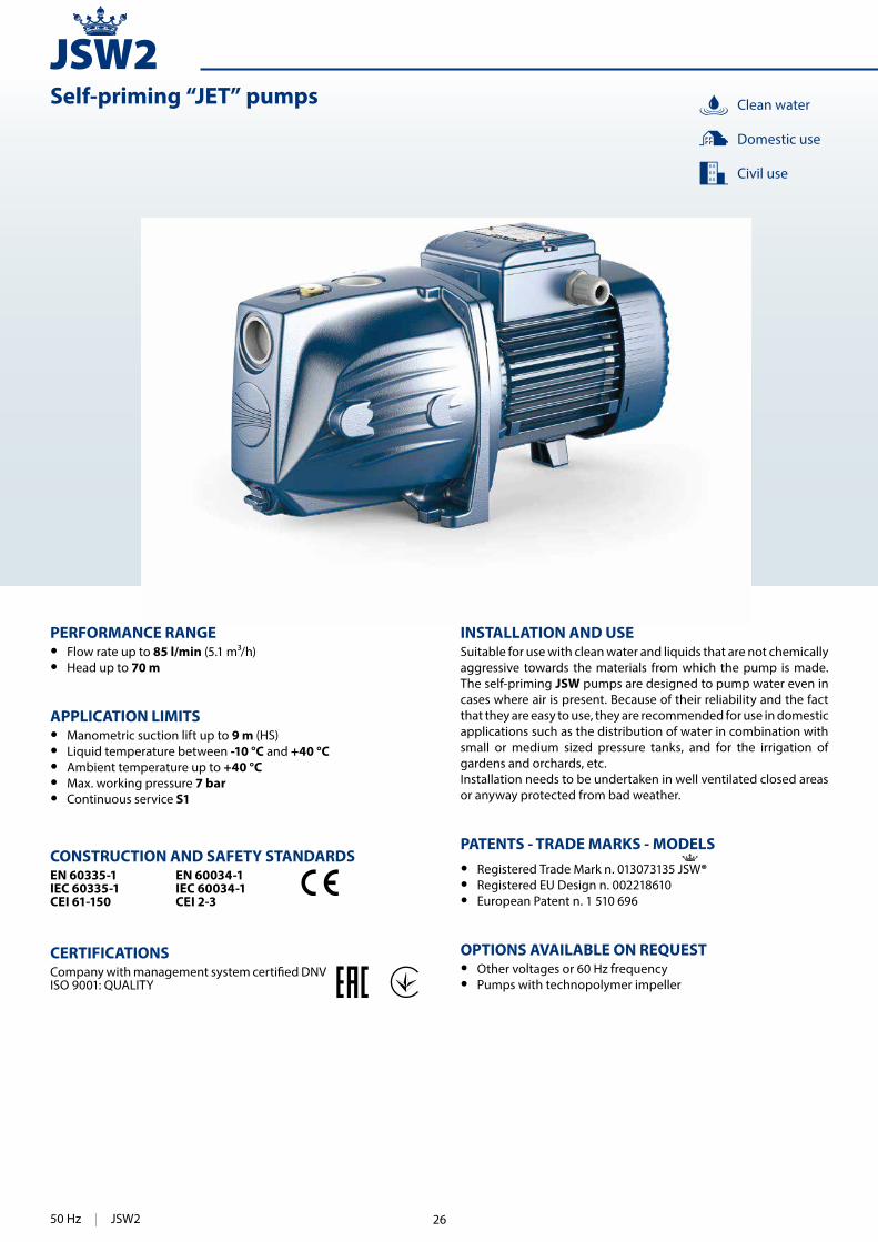
PERFORMANCE RANGE • Flow rate up to 85 l/min (5.1 m³/h) • Head up to 70 m
APPLICATION LIMITS • Manometric suction lift up to 9 m (HS) • Liquid temperature between -10 °C and +40 °C • Ambient temperature up to +40 °C • Max. working pressure 7 bar • Continuous service S1
CONSTRUCTION AND SAFETY STANDARDSEN 60335-1IEC 60335-1CEI 61-150
EN 60034-1IEC 60034-1CEI 2-3
CERTIFICATIONS
ISO 9001: QUALITY
INSTALLATION AND USESuitable for use with clean water and liquids that are not chemically aggressive towards the materials from which the pump is made. The self-priming JSW pumps are designed to pump water even in cases where air is present. Because of their reliability and the fact that they are easy to use, they are recommended for use in domestic applications such as the distribution of water in combination with small or medium sized pressure tanks, and for the irrigation of gardens and orchards, etc.Installation needs to be undertaken in well ventilated closed areas or anyway protected from bad weather.
PATENTS - TRADE MARKS - MODELS • Registered Trade Mark n. 013073135 JSW® • Registered EU Design n. 002218610 • European Patent n. 1 510 696
OPTIONS AVAILABLE ON REQUEST • Other voltages or 60 Hz frequency • Pumps with technopolymer impeller
Clean water
Domestic use
Civil use
JSW2Self-priming “JET” pumps
50 Hz | JSW2 26

93
0 5 10 15 20 25 30 35 40 45 50 55 60 65 7015
20
25
30
35
40
45
50
55
60
0
50
100
150
200
0 5 10 15
0 5 10 15
0 0.5 1 1.5 2 2.5 3 3.5 4
US g.p.m.
Imp g.p.m.feet
l/min
m³/h
JSW2
HS = 9 m
8
7
65
4
23
1
HS = 9 m
8
7
65
4
23
1
HS = 9 m
8
7
65
4
23
1
JSW2A
JSW2B
JSW2C
0 5 10 15 20 25 30 35 40 45 50 55 60 65 70 75 80 855
10
15
20
25
30
35
40
45
50
55
60
65
70
0
50
100
150
200
0 5 10 15 20
0 5 10 15
0 1 2 3 4 5
US g.p.m.
Imp g.p.m.feet
l/min
m³/h
JSW2JSW2AH
JSW2CM
JSW2CL
HS = 9 m8
76
54
23
1
HS = 9 m
HS = 9 m
8
8
7
7
6
6
5
5
4
4
2
2
3
3
1
1
CHARACTERISTIC CURVES AND PERFORMANCE DATA 50 Hz n= 2900 min HS= 0 m
Flow rate Q
Flow rate Q
Hea
d H
(m
etre
s)
Hea
d H
(m
etre
s)
MODELQ
m³/h 0 0.3 0.6 1.2 1.8 2.4 2.7 3.0 3.6 4.2 4.8 5.1
Single-phase Three-phase kW HP l/min 0 5 10 20 30 40 45 50 60 70 80 85
JSWm 2C JSW 2C 0.75 1
IE3 H metres
50 47 44 38.5 34 29.5 27.5 26 22.5 20
JSWm 2B JSW 2B 0.90 1.25 54 51 48 42.5 38 33.5 31.5 30 26.5 24
JSWm 2A JSW 2A 1.1 1.5 58 55 52 46.5 42 37.5 35.5 34 31 28
JSWm 2CM JSW 2CM 0.75 1 44 42 40 35.5 31.5 28 26 24.5 22 19.5 18
JSWm 2CL JSW 2CL 0.75 1 38 36 34 30 26 22.5 21 19.5 17 14.5 13 12
JSWm 2AH JSW 2AH 1.1 1.5 70 65 60 50.5 41.5 34.5 32
Q = Flow rate H = Total manometric head HS = Suction height Tolerance of characteristic curves in compliance with EN ISO 9906 Grade 3B.
JSW2 | 50 Hz = Stocked in Australia
Other models available upon request with 6 to 8 weeks lead time. 27
94
JSW2
2
0 bar
4 6
8
10
2
0 bar
4 6
8
10
1 43 6 95
772 8
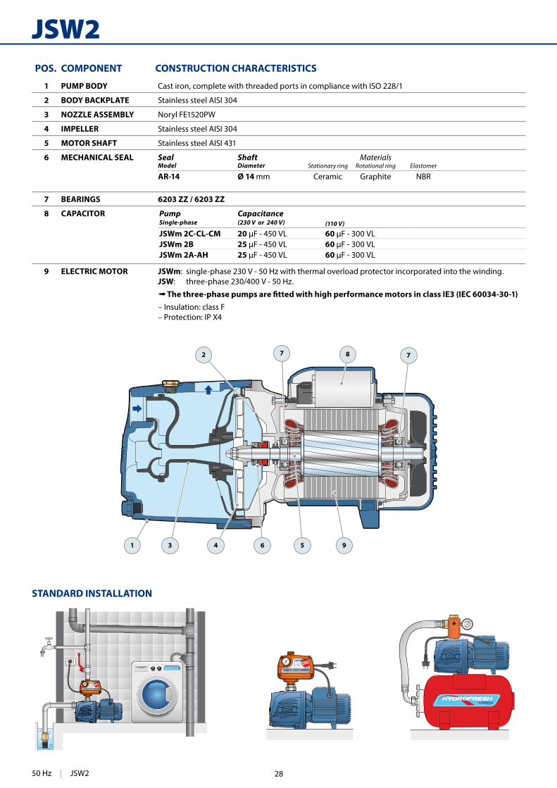
POS. COMPONENT CONSTRUCTION CHARACTERISTICS
1 PUMP BODY Cast iron, complete with threaded ports in compliance with ISO 228/1
2 BODY BACKPLATE Stainless steel AISI 304
3 NOZZLE ASSEMBLY Noryl FE1520PW
4 IMPELLER Stainless steel AISI 304
5 MOTOR SHAFT Stainless steel AISI 431
6 MECHANICAL SEAL Seal Shaft MaterialsModel Diameter Stationary ring Rotational ring Elastomer
AR-14 Ø 14 mm Ceramic Graphite NBR
7 BEARINGS 6203 ZZ / 6203 ZZ
8 CAPACITOR Pump CapacitanceSingle-phase (230 V or 240 V) (110 V)
JSWm 2C-CL-CM 20 60 JSWm 2B 25 60 JSWm 2A-AH 25 60
9 ELECTRIC MOTOR JSWm: single-phase 230 V - 50 Hz with thermal overload protector incorporated into the winding.JSW: three-phase 230/400 V - 50 Hz.
➠ The three-phase pumps are �tted with high performance motors in class IE3 (IEC 60034-30-1)– Insulation: class F – Protection: IP X4
STANDARD INSTALLATION
50 Hz | JSW2 28

95
f
a
DN2
h3
h1
DN
1
w
t
n2s
h
h2
DIMENSIONS AND WEIGHT
MODEL GROUPAGE CONTAINER
Single-phase Three-phase n. pumps n. pumps
JSWm 2C JSW 2C 72 96
JSWm 2B JSW 2B 72 96
JSWm 2A JSW 2A 72 96
JSWm 2CM JSW 2CM 72 96
JSWm 2CL JSW 2CL 72 96
JSWm 2AH JSW 2AH 72 96
ABSORPTION
PALLETIZATION
MODEL VOLTAGE
Three-phase 230 V 400 V 690 V 240 V 415 V 720 V
JSW 2C 3.5 A 2.0 A 1.2 A 3.4 A 1.9 A 1.1 A
JSW 2B 4.6 A 2.7 A 1.6 A 4.5 A 2.6 A 1.5 A
JSW 2A 5.1 A 3.0 A 1.7 A 4.9 A 2.8 A 1.7 A
JSW 2CM 3.5 A 2.0 A 1.2 A 3.3 A 1.9 A 1.1 A
JSW 2CL 3.2 A 1.8 A 1.0 A 2.9 A 1.7 A 1.0 A
JSW 2AH 5.1 A 3.0 A 1.7 A 5.0 A 2.9 A 1.7 A
MODEL VOLTAGE
Single-phase 230 V 240 V 110 V
JSWm 2C 4.7 A 4.5 A 9.4 A
JSWm 2B 5.8 A 5.3 A 11.6 A
JSWm 2A 6.0 A 5.5 A 12.0 A
JSWm 2CM 4.7 A 4.5 A 9.4 A
JSWm 2CL 3.8 A 3.6 A 7.6 A
JSWm 2AH 6.0 A 5.8 A 12.0 A
MODEL PORTS DIMENSIONS mm kg
Single-phase Three-phase DN1 DN2 a f h h1 h2 h3 t n2 w s 1~ 3~
JSWm 2C JSW 2C
1" 1" 96 389 200 * 147 33 180 180 142 22 10
13.1 12.9
JSWm 2B JSW 2B 14.0 13.9
JSWm 2A JSW 2A 14.7 14.4
JSWm 2CM JSW 2CM 12.9 13.0
JSWm 2CL JSW 2CL 13.0 13.0
JSWm 2AH JSW 2AH 14.2 14.3
(*) h=220 mm for single-phase versions at 110 V
JSW2 | 50 Hz29

96
JSW3
INSTALLATION AND USESuitable for use with clean water and with liquids that are not chemically aggressive towards the materials from which the pump is made. The self-priming JSW pumps are designed to pump water even in cases where air is present. Because of their reliability and the fact that they are easy to use, they are recommended for use in domestic, civil and industrial applications such as the distribution of water in combination with pressure tanks, and for the irrigation of gardens and orchards, etc.Installation needs to be undertaken in well ventilated closed areas or anyway protected from bad weather.
PATENTS - TRADE MARKS - MODELS • Registered Trade Mark n. 013073135 JSW® • Registered EU Design n. 002218610
OPTIONS AVAILABLE ON REQUEST • Other voltages or 60 Hz frequency • IPX5 protection
PERFORMANCE RANGE • Flow rate up to 160 l/min (9.6 m³/h) • Head up to 97 m
APPLICATION LIMITS • Manometric suction lift up to 9 m (HS) • Liquid temperature between -10 °C and +40 °C • Ambient temperature up to +40 °C • Max. working pressure 10 bar • Continuous service S1
CONSTRUCTION AND SAFETY STANDARDSEN 60335-1IEC 60335-1CEI 61-150
EN 60034-1IEC 60034-1CEI 2-3
CERTIFICATIONS
ISO 9001: QUALITY
Clean water
Domestic use
Civil use
Industrial use
Self-priming “JET” pumps
50 Hz | JSW3 30

97
0 10 20 30 40 50 60 70 80 90 100 110 120 130 140 150 16010
20
30
40
50
60
70
80
90
100
0 5 10 15 20 25 30 35 40
0 5 10 15 20 25 30 35
0 1 2 3 4 5 6 7 8 9
US g.p.m.
Imp g.p.m.feet
l/minm³/h
50
100
150
200
250
300JSW3AH
JSW3BH
JSW3AL
JSW3BL
JSW3CL
JSW3CH
JSW3AM
JSW3BM
JSW3CM
JSW3
Flow rate Q
Hea
d H
(m
etre
s)
CHARACTERISTIC CURVES AND PERFORMANCE DATA 50 Hz n= 2900 min HS= 0 m
STANDARD INSTALLATION
HS = Suction height
Non-return valve
Q = Flow rate H = Total manometric head HS = Suction height Tolerance of characteristic curves in compliance with EN ISO 9906 Grade 3B.
MODELQ
m³/h 0 0.6 1.2 1.8 2.4 3.0 3.6 4.2 4.8 6.0 7.2 8.4 9.6
Single-phase Three-phase kW HP l/min 0 10 20 30 40 50 60 70 80 100 120 140 160
JSWm 3CH JSW 3CH 1.1 1.5
IE3 H metres
62 55 49 45 41 38 35 32 30
JSWm 3BH JSW 3BH 1.5 2 73 68 62 56.5 52 48 44 41 38
JSWm 3AH JSW 3AH 2.2 3 97 88 81 75 70 65 60.5 56 52
JSWm 3CM JSW 3CM 1.1 1.5 54 – 46 43 39.5 36.5 34 31 28.5 24 20
JSWm 3BM JSW 3BM 1.5 2 63 – 56 53 49.5 47.5 44 41 39 34 30
JSWm 3AM JSW 3AM 2.2 3 78 – 70 66 62 59 56 53 50 45 40
JSWm 3CL JSW 3CL 1.1 1.5 44 – – 39 37 34 32 30 28 24 21 17 14
JSWm 3BL JSW 3BL 1.5 2 51 – – 46 44 42 40 38 36 33 30 27 24
JSWm 3AL JSW 3AL 2.2 3 64 – – 58 56 54 52 50 48 45 41.5 38.5 36
JSW3 | 50 Hz
= Stocked in Australia
Other models available upon request with 6 to 8 weeks lead time.
31
98
JSW3
1 4 63 95
77 82
POS. COMPONENT CONSTRUCTION CHARACTERISTICS
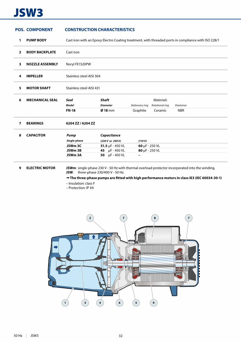
1 PUMP BODY Cast iron with an Epoxy Electro Coating treatment, with threaded ports in compliance with ISO 228/1
2 BODY BACKPLATE Cast iron
3 NOZZLE ASSEMBLY Noryl FE1520PW
4 IMPELLER Stainless steel AISI 304
5 MOTOR SHAFT Stainless steel AISI 431
6 MECHANICAL SEAL Seal Shaft MaterialsModel Diameter Stationary ring Rotational ring Elastomer
FN-18 Ø 18 mm Graphite Ceramic NBR
7 BEARINGS 6204 ZZ / 6204 ZZ
8 CAPACITOR Pump CapacitanceSingle-phase (230 V or 240 V) (110 V)
JSWm 3C 31.5 60 JSWm 3B 45 80 JSWm 3A 50 –
9 ELECTRIC MOTOR JSWm: single-phase 230 V - 50 Hz with thermal overload protector incorporated into the winding.JSW: three-phase 230/400 V - 50 Hz.
➠ The three-phase pumps are �tted with high performance motors in class IE3 (IEC 60034-30-1)– Insulation: class F – Protection: IP X4
50 Hz | JSW3 32

99
f
w
h3
h1h2
a
t
n2s
h
DN2
DN
1
DIMENSIONS AND WEIGHT
MODEL GROUPAGE CONTAINER
Single-phase Three-phase n. pumps n. pumps
JSWm 3CH JSW 3CH 35 49JSWm 3BH JSW 3BH 35 49JSWm 3AH JSW 3AH 35 49JSWm 3CM JSW 3CM 35 49JSWm 3BM JSW 3BM 35 49JSWm 3AM JSW 3AM 35 49JSWm 3CL JSW 3CL 35 49JSWm 3BL JSW 3BL 35 49JSWm 3AL JSW 3AL 35 49
ABSORPTION
PALLETIZATION
MODEL VOLTAGE
Three-phase 230 V 400 V 690 V 240 V 415 V 720 V
JSW 3CH 5.2 A 3.0 A 1.7 A 5.0 A 2.9 A 1.7 AJSW 3BH 6.0 A 3.5 A 2.0 A 5.8 A 3.4 A 1.9 AJSW 3AH 8.8 A 5.1 A 2.9 A 8.5 A 4.9 A 2.8 AJSW 3CM 5.2 A 3.0 A 1.7 A 5.0 A 2.9 A 1.7 AJSW 3BM 6.0 A 3.5 A 2.0 A 5.8 A 3.4 A 1.9 AJSW 3AM 9.0 A 5.2 A 3.0 A 8.6 A 5.0 A 2.9 AJSW 3CL 5.2 A 3.0 A 1.7 A 5.0 A 2.9 A 1.7 AJSW 3BL 6.4 A 3.7 A 2.1 A 6.1 A 3.6 A 2.0 AJSW 3AL 9.3 A 5.4 A 3.1 A 9.0 A 5.2 A 3.0 A
MODEL VOLTAGE
Single-phase 230 V 240 V 110 V
JSWm 3CH 8.1 A 7.8 A 16.2 A JSWm 3BH 9.5 A 9.2 A 19.0 A JSWm 3AH 12.7 A 12.4 A –JSWm 3CM 8.1 A 7.8 A 16.2 A JSWm 3BM 9.7 A 9.4 A 19.4 A JSWm 3AM 13.0 A 12.5 A –JSWm 3CL 8.1 A 7.8 A 16.2 A JSWm 3BL 10.1 A 9.8 A 20.2 A JSWm 3AL 13.6 A 13.1 A –
MODEL PORTS DIMENSIONS mm kg
Single-phase Three-phase DN1 DN2 a f h h1 h2 h3 t n2 w s 1~ 3~
JSWm 3CH JSW 3CH
1¼" 1" 143
522
240 165 39 204 206 164 30 11
24.2 28.2JSWm 3BH JSW 3BH 25.5 25.4JSWm 3AH JSW 3AH 542 28.2 28.0JSWm 3CM JSW 3CM
52224.4 24.4
JSWm 3BM JSW 3BM 25.6 25.5JSWm 3AM JSW 3AM 542 28.0 28.2JSWm 3CL JSW 3CL
52224.4 24.3
JSWm 3BL JSW 3BL 25.6 25.5JSWm 3AL JSW 3AL 542 28.2 28.2
JSW3 | 50 Hz33

74
2-5CR 60-80-100
INSTALLATION AND USESuitable for use with clean water and with liquids that are not chemically aggressive towards the materials from which the pump is made. As a result of their quietness these pumps are widely used in domestic applications such as the distribution of water in combination with small and medium sized pressure tanks, and for the irrigation of gardens and orchards, etc.The pump should be installed in an enclosed environment or sheltered from inclement weather.
OPTIONS AVAILABLE ON REQUEST • Special mechanical seal • Other voltages or 60 Hz frequency
PERFORMANCE RANGE • Flow rate up to 130 l/min (7.8 m³/h) • Head up to 67 m
APPLICATION LIMITS • Manometric suction lift up to 7 m • Liquid temperature between -10 °C and +40 °C • Ambient temperature up to +40 °C • Max. working pressure 7 bar • Continuous service S1
CONSTRUCTION AND SAFETY STANDARDSEN 60335-1IEC 60335-1CEI 61-150
EN 60034-1IEC 60034-1CEI 2-3
CERTIFICATIONS
ISO 9001: QUALITY
Multi-stage centrifugal pumpsClean water
Domestic use
Civil use
50 Hz | 2-5CR 60-80-100 34

75
0 10 20 30 40 50 60 70 80 90 100 110 120 1300
10
20
30
40
50
60
70
0
0
25
50
75
100
124
150
175
200
0 5 10 15 20 25 30
0 5 10 15 20 25
0 1 2 3 4 5 6 7 8
US g.p.m.
Imp g.p.m.feet
l/minm³/h
4CR100
4CR80
3CR80
3CR100
3CR60
2CR80
5CR80
5CR100
CHARACTERISTIC CURVES AND PERFORMANCE DATA 50 Hz n= 2900 min HS= 0 m
Flow rate Q
Hea
d H
(m
etre
s)
Q = Flow rate H = Total manometric head HS = Suction height Tolerance of characteristic curves in compliance with EN ISO 9906 Grade 3B.
Performance class of the three-phase motor (IEC 60034-30-1)
MODELQ
m³/h 0 0.3 0.6 0.9 1.2 1.5 1.8 2.4 3.0 3.6 4.2 4.8 5.4 6.0 6.6 7.2 7.8
Single-phase Three-phase kW HP l/min 0 5 10 15 20 25 30 40 50 60 70 80 90 100 110 120 130
2CRm 80 2CR 80 0.37 0.50
IE2
H metres
27 26 25 24 22.5 21 20 16.5 13 9 5
3CRm 60 3CR 60 0.37 0.50 31 30 29 28 26.5 25 23.5 20 16 11.5 7
3CRm 80 3CR 80 0.45 0.60 40 38 37 36 34.5 33 31 27 22.5 17 11 5
4CRm 80 4CR 80 0.55 0.75 52 50 49 47 44.5 42 40 34 28.5 22.5 16 10
5CRm 80 5CR 80 0.75 1 IE3 67 66 64 62 59 56 53 45.5 37.5 29.5 20.5 12
3CRm 100 3CR 100 0.55 0.75 IE2 38 37 36 35 34.5 33.5 33 31 28 26 23 20 17 13.5 10 5
4CRm 100 4CR 100 0.75 1IE3
50 50 49 48 47 46 45 42 39.5 37 34 30.5 26.5 22 17 11 5
5CRm 100 5CR 100 1.1 1.5 63 62 61.5 60.5 59.5 58 57 53.5 50.5 46.5 42.5 38 33 28 22 15 8
2-5CR 60-80-100 | 50 Hz
= Stocked in Australia
Other models available upon request with 6 to 8 weeks lead time.
35
76
2-5CR 60-80-100
1 9
77 8
3 52
64
POS. COMPONENT CONSTRUCTION CHARACTERISTICS
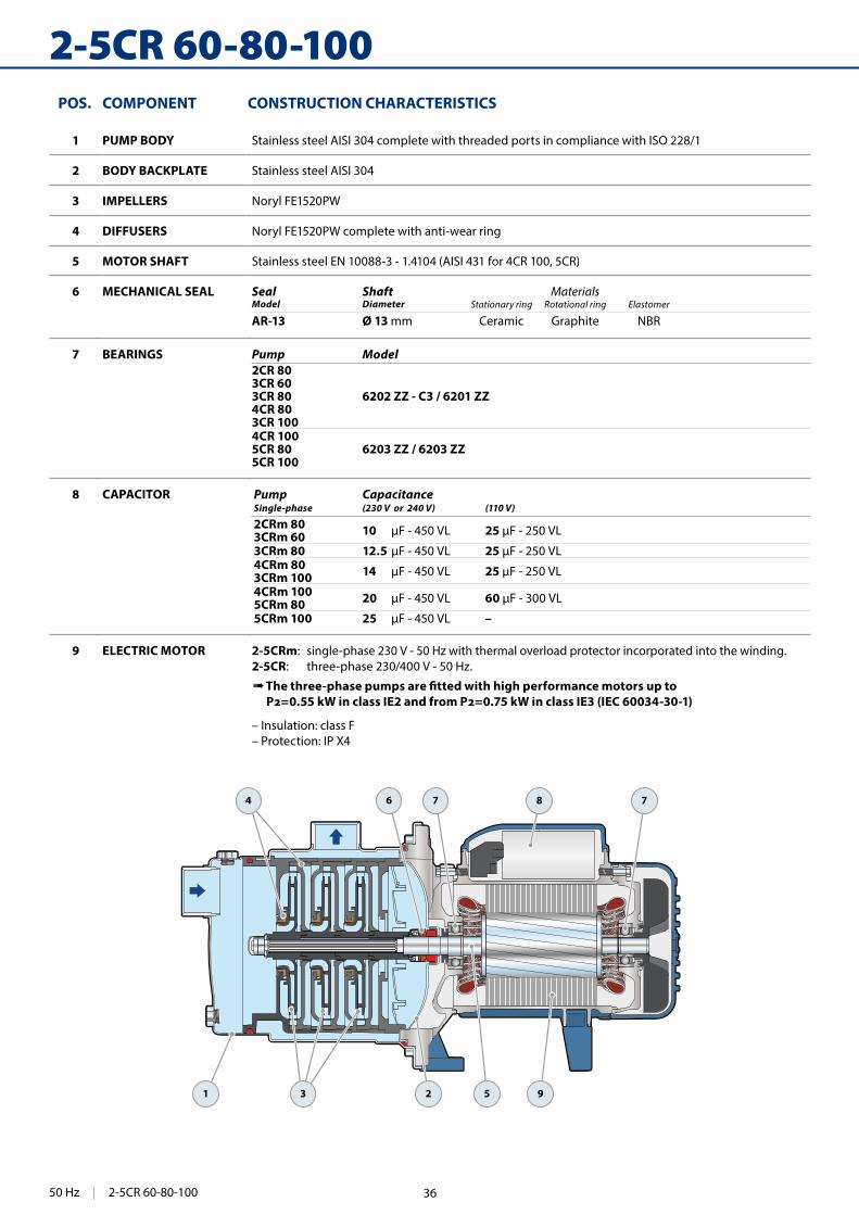
1 PUMP BODY Stainless steel AISI 304 complete with threaded ports in compliance with ISO 228/1
2 BODY BACKPLATE Stainless steel AISI 304
3 IMPELLERS Noryl FE1520PW
4 DIFFUSERS Noryl FE1520PW complete with anti-wear ring
5 MOTOR SHAFT Stainless steel EN 10088-3 - 1.4104 (AISI 431 for 4CR 100, 5CR)
6 MECHANICAL SEAL Seal Shaft MaterialsModel Diameter Stationary ring Rotational ring Elastomer
AR-13 Ø 13 mm Ceramic Graphite NBR
7 BEARINGS Pump Model2CR 803CR 603CR 804CR 803CR 100
6202 ZZ - C3 / 6201 ZZ
4CR 1005CR 805CR 100
6203 ZZ / 6203 ZZ
8 CAPACITOR Pump CapacitanceSingle-phase (230 V or 240 V) (110 V)
2CRm 80 3CRm 60 10 25
3CRm 80 12.5 25 4CRm 803CRm 100 14 25
4CRm 1005CRm 80 20 60
5CRm 100 25 –
9 ELECTRIC MOTOR 2-5CRm: single-phase 230 V - 50 Hz with thermal overload protector incorporated into the winding.2-5CR: three-phase 230/400 V - 50 Hz.
➠ The three-phase pumps are �tted with high performance motors up to IEC 60034-30-1)
– Insulation: class F– Protection: IP X4
50 Hz | 2-5CR 60-80-100 36

77
hh3
DN
1
h1
f
aDN2
w
t
n2s
h2
DIMENSIONS AND WEIGHT
ABSORPTION
PALLETIZATION
MODEL GROUPAGE CONTAINER
Single-phase Three-phase n. pumps n. pumps
2CRm 80 2CR 80 84 108
3CRm 60 3CR 60 84 108
3CRm 80 3CR 80 84 108
4CRm 80 4CR 80 72 108
5CRm 80 5CR 80 72 108
3CRm 100 3CR 100 84 108
4CRm 100 4CR 100 72 108
5CRm 100 5CR 100 72 108
(*) h=221 mm for single phase versions at 110V
MODEL VOLTAGE
Three-phase 230 V 400 V 690 V 240 V 415 V 720 V
2CR 80 1.7 A 1.0 A 0.6 A 1.7 A 1.0 A 0.6 A
3CR 60 1.7 A 1.0 A 0.6 A 1.7 A 1.0 A 0.6 A
3CR 80 2.5 A 1.5 A 0.9 A 2.4 A 1.4 A 0.8 A
4CR 80 3.4 A 2.0 A 1.2 A 3.3 A 1.9 A 1.1 A
5CR 80 4.3 A 2.5 A 1.4 A 4.1 A 2.4 A 1.3 A
3CR 100 3.4 A 2.0 A 1.2 A 3.3 A 1.9 A 1.1 A
4CR 100 4.0 A 2.3 A 1.3 A 3.8 A 2.2 A 1.3 A
5CR 100 4.3 A 2.5 A 1.4 A 4.2 A 2.4 A 1.4 A
MODEL PORTS DIMENSIONS mm kg
Single-phase Three-phase DN1 DN2 a f h h1 h2 h3 t n2 w s 1~ 3~
2CRm 80 2CR 80
1” 1”
113 367182
132 51 183 182 120 87
9
6.5 6.5
3CRm 60 3CR 60 6.5 6.5
3CRm 80 3CR 80 7.3 7.3
4CRm 80 4CR 80138
392 8.3 7.7
5CRm 80 5CR 80 411 202 * 10 10.7 10.7
3CRm 100 3CR 100 113 367 182 9 7.9 7.3
4CRm 100 4CR 100138 410 202 * 10
10.6 10.6
5CRm 100 5CR 100 11.0 10.6
MODEL VOLTAGE
Single-phase 230 V 240 V 110 V
2CRm 80 2.2 A 2.1 A 4.4 A
3CRm 60 2.4 A 2.3 A 4.8 A
3CRm 80 3.3 A 3.3 A 6.6 A
4CRm 80 3.8 A 3.6 A 7.6 A
5CRm 80 5.5 A 5.2 A 11.0 A
3CRm 100 3.9 A 3.7 A 7.8 A
4CRm 100 6.0 A 6.0 A 12.0 A
5CRm 100 6.3 A 6.1 A 12.6 A
2-5CR 60-80-100 | 50 Hz37

64
3-7CR 90-130-200
INSTALLATION AND USESuitable for use with clean water and with liquids that are not chemically aggressive towards the materials from which the pump is made. As a result of their quietness these pumps are widely used in domestic applications such as the distribution of water in combination with small and medium sized pressure tanks, and for the irrigation of gardens and orchards, etc.Installation needs to be undertaken in well ventilated closed areas or anyway protected from bad weather.
PATENTS - TRADE MARKS - MODELS • Patent n. EP14755156.8
OPTIONS AVAILABLE ON REQUEST • Special mechanical seal • Other voltages or 60 Hz frequency • IPX5 class protection
PERFORMANCE RANGE • Flow rate up to 200 l/min (12 m³/h) • Head up to 111 m
APPLICATION LIMITS • Manometric suction lift up to 7 m • Liquid temperature between -10 °C and +90 °C • Ambient temperature up to +40 °C • Max. working pressure 10 bar • Continuous service S1
CONSTRUCTION AND SAFETY STANDARDSEN 60335-1IEC 60335-1CEI 61-150
EN 60034-1IEC 60034-1CEI 2-3
CERTIFICATIONS
ISO 9001: QUALITY
Multi-stage centrifugal pumpsClean water
Domestic use
Civil use
STAINLESS STEEL IMPELLERS
50 Hz | 3-7CR 90-130-200 38

65
0 10 20 30 40 50 60 70 80 90 100 110 120 130 140 150 160 170 180 190 20010
20
30
40
50
60
70
80
90
100
110
50
100
150
200
250
300
350
0 10 20 30 40 50
0 10 20 30 40
0 1 2 3 4 5 6 7 8 9 10 11 12
5CR200
6CR200
4CR200
3CR200
6CR90
7CR90
5CR90
6CR130
5CR130
4CR130
3CR130
US g.p.m.
Imp g.p.m.feet
l/minm³/h
Flow rate Q
Hea
d H
(m
etre
s)
CHARACTERISTIC CURVES AND PERFORMANCE DATA 50 Hz n= 2900 min HS= 0 m
MODELQ
m³/h 0 0.3 0.6 1.2 2.4 3.6 4.8 5.4 6.0 7.8 8.4 9.6 10.8 12.0
Single-phase Three-phase kW HP l/min 0 5 10 20 40 60 80 90 100 130 140 160 180 200
5CRm 90 5CR 90 1.1 1.5
IE3 H metres
80 78 77 74 67 57 45 38
6CRm 90 6CR 90 1.5 2 96 94 92 88 80 69 53 45
7CRm 90 7CR 90 1.8 2.5 111 110 108 103 93 80 63 53
3CRm 130 3CR 130 1.1 1.5 49 49 48.5 47.5 45 42.5 38.5 36 33.5 24
4CRm 130 4CR 130 1.5 2 65 65 64 63 60 56 50 47 43 31
5CRm 130 5CR 130 1.8 2.5 81 81 80.5 79 75 70 62.5 59 54 39
– 6CR 130 2.2 3 97 97 96.5 94.5 90 83 74.5 69 64 46
3CRm 200 3CR 200 1.1 1.5 44 43.5 43.5 43 42 40.5 38 36.5 35 29 27.5 23 18 13
4CRm 200 4CR 200 1.5 2 58 57.5 57.5 57 55 52.5 49.5 47 45 38 35.5 30 24 17
5CRm 200 5CR 200 1.8 2.5 73 72 71.5 71 69 65.5 62 59 56.5 48 44.5 38 30 22
– 6CR 200 2.2 3 87 86 85.5 85 82 78 73 69 67 57 53 45 36 26
Q = Flow rate H = Total manometric head HS = Suction height Tolerance of characteristic curves in compliance with EN ISO 9906 Grade 3B.
3-7CR 90-130-200 | 50 Hz
= Stocked in Australia
Other models available upon request with 6 to 8 weeks lead time.
39

66
3-7CR 90-130-200
5 6 9
774 1 2 83
POS. COMPONENT CONSTRUCTION CHARACTERISTICS
1 PUMP BODY Stainless steel AISI 304 complete with threaded ports in compliance with ISO 228/1
2 BODY BACKPLATE Stainless steel AISI 304
3 IMPELLERS Stainless steel AISI 304
4 DIFFUSERS Stainless steel AISI 304
5 MOTOR SHAFT Stainless steel AISI 431
6 MECHANICAL SEAL Seal Shaft MaterialsModel Diameter Stationary ring Rotational ring Elastomer
FN-18 Ø 18 mm Graphite Silicon carbide EPDM
7 BEARINGS 6304 2RS - C3 / 6204 ZZ - C3E
8 CAPACITOR Pump CapacitanceSingle-phase (230 V or 240 V) (110 V)
5CRm 903CRm 1303CRm 200
31.5 60
6CRm 904CRm 1304CRm 200
45 80
7CRm 905CRm 1305CRm 200
50 –
9 ELECTRIC MOTOR 3-7CRm: single-phase 230 V - 50 Hz with thermal overload protector incorporated into the winding.3-7CR: three-phase 230/400 V - 50 Hz.
➠ The three-phase pumps are �tted with high performance motors in class IE3 (IEC 60034-30-1)– Insulation: class F – Protection: IP X4
50 Hz | 3-7CR 90-130-200 40

67
f
DN2
a
h1h2
w
t
h
n2
s
DN
1DIMENSIONS AND WEIGHT
ABSORPTION
MODEL VOLTAGE
Three-phase 230 V 400 V 690 V 240 V 415 V 720 V
5CR 90 6.1 A 3.5 A 2.0 A 5.9 A 3.4 A 1.9 A
6CR 90 6.9 A 4.0 A 2.3 A 6.6 A 3.8 A 2.2 A
7CR 90 8.3 A 4.8 A 2.8 A 8.0 A 4.6 A 2.7 A
3CR 130 5.6 A 3.2 A 1.8 A 5.4 A 3.1 A 1.8 A
4CR 130 6.9 A 4.0 A 2.3 A 6.6 A 3.8 A 2.2 A
5CR 130 8.7 A 5.0 A 2.9 A 8.3 A 4.8 A 2.8 A
6CR 130 9.0 A 5.2 A 3.0 A 8.6 A 5.0 A 2.9 A
3CR 200 5.9 A 3.4 A 2.0 A 5.7 A 3.3 A 1.9 A
4CR 200 7.3 A 4.2 A 2.4 A 6.9 A 4.0 A 2.3 A
5CR 200 8.7 A 5.0 A 2.9 A 8.3 A 4.8 A 2.8 A
6CR 200 9.5 A 5.5 A 3.2 A 9.2 A 5.3 A 3.0 A
MODEL VOLTAGE
Single-phase 230 V 240 V 110 V
5CRm 90 9.0 A 8.6 A 18.0 A
6CRm 90 10.5 A 10.1 A 21.0 A
7CRm 90 12.5 A 12.0 A –
3CRm 130 8.5 A 8.1 A 17.0 A
4CRm 130 10.3 A 9.9 A 26.0 A
5CRm 130 12.5 A 12.0 A –
3CRm 200 8.7 A 8.3 A 17.4 A
4CRm 200 10.5 A 10.1 A 21.0 A
5CRm 200 12.5 A 12.0 A –
MODEL PORTS DIMENSIONS mm kg
Single-phase Three-phase DN1 DN2 a f h h1 h2 t n2 w s 1~ 3~
5CRm 90 5CR 90
1¼" 1" 73
497
228 145 56 185 145
193
11
20.3 19.8
6CRm 90 6CR 90 523 219 21.0 21.9
7CRm 90 7CR 90 569 245 26.0 26.0
3CRm 130 3CR 130 445 141 18.1 18.1
4CRm 130 4CR 130 471 167 20.0 20.1
5CRm 130 5CR 130 517 193 23.7 23.8
– 6CR 130 543 219 – 24.8
3CRm 200 3CR 200 445 141 18.1 18.1
4CRm 200 4CR 200 471 167 20.0 20.1
5CRm 200 5CR 200 518 193 23.7 23.6
– 6CR 200 543 219 – 24.4
3-7CR 90-130-200 | 50 Hz41

140
TISSEL-200
TS2-MK
TS2-CR
Q1 Q2 Q3
30 Hz1 HP
50 Hz3 HP
TS2-PLURIJET
ENERGY SAVINGSAs it works at variable speed, TISSEL 200 uses only the necessary energy demand required by the system according to the water de-mand.
DESCRIPTION• TISSEL 200 are compact pumping units consisting of one cen-
trifugal waterpump coupled with a variable speed device(in-verter) with an external pressure sensor to be placed in a place inside the system.
• Sturdy and simple to use,TISSEL 200 is ideal to keep always con-stant pressure inside system regardless variation of utilities.
• Built-in speed regulator with automatic fan ventilation and IP54 protection. Powered by single-phase alternate tension (230±10% V - 50/60 Hz) it gives an output alternate 3phase ten-sion to run waterpump motor in IE3 class.
• Smooth start and stop of the pump . • Lower wear of the waterpump due to modulation of running
speed from the inverter.
PROTECTIONS• Dry running
Microchip action stops pump after few seconds and try sched-uled set restarts to check water availability.
• Running pressure lower than minimum set runningIt stops the pump after few seconds ( i.e. when there is a break in a pipe).
• Currents-tensions-temperatures It limits currents; it informs whether tension reaches the allowed limits, it protects from overheating as well as short circuits be-tween the output phases.
CONSTRUCTION AND SAFETY STANDARDSEN 60335-1IEC 60335-1CEI 61-150
EN 60034-1IEC 60034-1CEI 2-3
CERTIFICATIONS
ISO 9001: QUALITY
ENER
GYSA
VING
S
ENER
GYSA
VING
S
SET-POINT pressure set
Pumps with inverterClean water
Domestic use
Civil use
Head
Flow rate
50 Hz | TISSEL-200 42

141
TISSEL-200 MK
0 25 50 75 100 125 150 1750
10
20
30
40
50
60
70
80
90
100
110
0
100
200
300
US g.p.m.
Imp g.p.m.feet
l/minm³/h
0 10 20 30 40
0 10 20 30 40
0 1 2 3 4 5 6 7 8 9 10 11
TS2-MK 3 TS2-MK 5 TS2-MK 8
PERFORMANCE RANGE n= 2900 min
Flow rate Q
Hea
d H
(met
res )
MODEL POWER ABSORPTION MAX PERFORMANCES PERFORMANCES (ADJUSTABLE SET POINT)P2 230 V Q H Min. Set Point Set Point Stand. Setting Max. Set Point
Single-phase kW HP l/min metres bar l/min bar l/min bar l/minTS2-MK 3/3 0.75 1
IE3
9.0 A 5 – 80 46 – 28 1.8 5 – 63 3.7 5 – 58 4.5 5 – 35TS2-MK 3/4 1.1 1.5 9.0 A 5 – 80 62 – 38 2.4 5 – 62 4.9 5 – 58 6.1 5 – 33TS2-MK 3/5 1.1 1.5 13.0 A 5 – 80 80 – 47 3.0 5 – 62 6.2 5 – 58 7.8 5 – 28TS2-MK 3/6 1.5 2 13.0 A 5 – 80 96 – 56 3.6 5 – 63 7.4 5 – 58 9.4 5 – 25TS2-MK 5/4 1.1 1.5 10.0 A 5 – 120 50 – 20 2.0 5 – 120 3.7 5 – 85 4.9 5 – 48TS2-MK 5/5 1.1 1.5 12.0 A 5 – 120 63 – 25 2.5 5 – 120 4.6 5 – 85 6.2 5 – 48TS2-MK 5/6 1.5 2 13.5 A 5 – 120 78 – 30 3.0 5 – 120 5.5 5 – 85 7.6 5 – 45TS2-MK 5/7 1.8 2.5 16.0 A 5 – 120 92 – 34 3.5 5 – 118 6.5 5 – 85 9.0 5 – 43TS2-MK 5/8 2.2 3 17.5 A 5 – 120 102 – 40 4.0 5 – 120 7.5 5 – 85 10.0 5 – 46TS2-MK 8/4 1.5 2 14.0 A 5 – 180 50 – 15 2.0 5 – 167 3.7 5 – 120 4.9 5 – 70TS2-MK 8/5 1.8 2.5 15.0 A 5 – 180 64 – 18 2.5 5 – 167 4.8 5 – 120 6.3 5 – 70TS2-MK 8/6 2.2 3 16.0 A 5 – 180 80 – 20 3.1 5 – 163 5.5 5 – 120 7.8 5 – 53
TISSEL-200 | 50 Hz43

142
0 10 20 30 40 50 60 70 80 900
10
20
30
40
50
60
H (m
)
Q (l/min)
TS2-MK 3/3
50 Hz
30 Hz
Set point 3.7 bar
min 1.8 bar
max 4.5 bar
0 10 20 30 40 50 60 70 80 900
10
20
30
40
50
60
70
80
90
100
H (m
)
Q (l/min)
TS2-MK 3/5
30 Hz
50 Hz
Set point 6.2 bar
min 3.0 bar
max 7.8 bar
0 10 20 30 40 50 60 70 80 90 100 110 120 1300
10
20
30
40
50
60
H (m
)
Q (l/min)
TS2-MK 5/4
50 Hz
30 Hz
Set point 3.7 bar
min 2.0 bar
max 4.9 bar
0 10 20 30 40 50 60 70 80 900
10
20
30
40
50
60
70
80
H (m
)
Q (l/min)
TS2-MK 3/4
50 Hz
30 Hz
Set point 4.9 bar
min 2.4 bar
max 6.1 bar
0 10 20 30 40 50 60 70 80 900
10
20
30
40
50
60
70
80
90
100
110H
(m)
Q (l/min)
TS2-MK 3/6
30 Hz
50 Hz
Set point 7.4 bar
min 3.6 bar
max 9.4 bar
0 10 20 30 40 50 60 70 80 90 100 110 120 1300
10
20
30
40
50
60
70
80
H (m
)
Q (l/min)
TS2-MK 5/5
50 Hz
30 Hz
Set point 4.6 bar
min 2.5 bar
max 6.2 bar
TISSEL-200 MKCHARACTERISTIC CURVES n= 2900 min
50 Hz | TISSEL-200 44

143
0 10 20 30 40 50 60 70 80 90 100 110 120 1300
10
20
30
40
50
60
70
80
90
100
H (m
)
Q (l/min)
TS2-MK 5/6
50 Hz
30 Hz
Set point 5.5 bar
min 3.0 bar
max 7.6 bar
0 10 20 30 40 50 60 70 80 90 100 110 120 1300
10
20
30
40
50
60
70
80
90
100
110
120
H (m
)
Q (l/min)
TS2-MK 5/8
50 Hz
30 Hz
Set point 7.5 bar
min 4.0 bar
max 10.0 bar
0 20 40 60 80 100 120 140 160 180 2000
10
20
30
40
50
60
70
80
H (m
)
Q (l/min)
TS2-MK 8/5
50 Hz
30 Hz
Set point 4.8 bar
min 2.5 bar
max 6.3 bar
0 10 20 30 40 50 60 70 80 90 100 110 120 1300
10
20
30
40
50
60
70
80
90
100
110
H (m
)
Q (l/min)
TS2-MK 5/7
50 Hz
30 Hz
Set point 6.5 bar
min 3.5 bar
max 9.0 bar
0 20 40 60 80 100 120 140 160 180 2000
10
20
30
40
50
60H
(m)
Q (l/min)
TS2-MK 8/4
50 Hz
30 Hz
Set point 3.7 bar
min 2.0 bar
max 4.9 bar
0 20 40 60 80 100 120 140 160 180 2000
10
20
30
40
50
60
70
80
90
100
H (m
)
Q (l/min)
TS2-MK 8/6
50 Hz
30 Hz
Set point 5.5 bar
min 3.1 bar
max 7.8 bar
CHARACTERISTIC CURVES n= 2900 min
TISSEL-200 | 50 Hz45
144
TISSEL-200 CR
0
100
200
300
0 25 50 75 100 125 150 1750
10
20
30
40
50
60
70
80
90
100
110 feet
l/minm³/h0 1 2 3 4 5 6 7 8 9 10 11
0 10 20 30 40
0 10 20 30 40
US g.p.m.
Imp g.p.m.
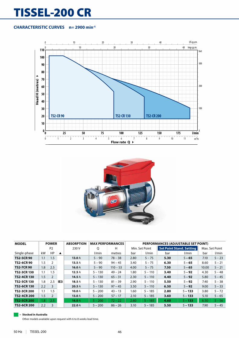
TS2-CR 90 TS2-CR 130 TS2-CR 200
CHARACTERISTIC CURVES n= 2900 min
MODEL POWER ABSORPTION MAX PERFORMANCES PERFORMANCES (ADJUSTABLE SET POINT)P2 230 V Q H Min. Set Point Set Point Stand. Setting Max. Set Point
Single-phase kW HP l/min metres bar l/min bar l/min bar l/minTS2-5CR 90 1.1 1.5
IE3
13.0 A 5 – 90 78 – 38 2.80 5 – 75 5.30 5 – 65 7.10 5 – 23TS2-6CR 90 1.5 2 13.5 A 5 – 90 94 – 45 3.40 5 – 75 6.30 5 – 65 8.60 5 – 21TS2-7CR 90 1.8 2.5 16.0 A 5 – 90 110 – 53 4.00 5 – 75 7.50 5 – 65 10.00 5 – 21TS2-3CR 130 1.1 1.5 12.5 A 5 – 130 49 – 24 1.80 5 – 110 3.40 5 – 92 4.30 5 – 48TS2-4CR 130 1.5 2 14.5 A 5 – 130 65 – 31 2.30 5 – 110 4.40 5 – 92 5.80 5 – 45TS2-5CR 130 1.8 2.5 18.5 A 5 – 130 81 – 39 2.90 5 – 110 5.50 5 – 92 7.40 5 – 38TS2-6CR 130 2.2 3 20.5 A 5 – 130 97 – 45 3.50 5 – 110 6.50 5 – 92 9.00 5 – 33TS2-3CR 200 1.1 1.5 10.0 A 5 – 200 43 – 13 1.60 5 – 185 2.80 5 – 133 3.80 5 – 72TS2-4CR 200 1.5 2 13.0 A 5 – 200 57 – 17 2.10 5 – 185 3.60 5 – 133 5.10 5 – 65TS2-5CR 200 1.8 2.5 16.0 A 5 – 200 72 – 22 2.60 5 – 185 4.60 5 – 133 6.50 5 – 56TS2-6CR 200 2.2 3 22.0 A 5 – 200 86 – 26 3.10 5 – 185 5.50 5 – 133 7.90 5 – 45
Flow rate Q
Hea
d H
(met
res)
50 Hz | TISSEL-200
= Stocked in Australia
Other models available upon request with 6 to 8 weeks lead time.
46
145
0 10 20 30 40 50 60 70 80 90 1000
10
20
30
40
50
60
70
80
H (m
)
Q (l/min)
50 Hz
Set point 5.3 bar
min 2.8 bar
max 7.1 barTS2-5CR 90
0 10 20 30 40 50 60 70 80 90 1000
10
20
30
40
50
60
70
80
90
100
110
120
H (m
)
Q (l/min)
50 Hz
30 Hz
Set point 7.5 bar
min 4 bar
max 10 bar
TS2-7CR 90
0 10 20 30 40 50 60 70 80 90 100 110 120 130 1400
10
20
30
40
50
60
70
H (m
)
Q (l/min)
50 Hz
30 Hz
Set point 4.4 bar
min 2.3 bar
max 5.8 bar
TS2-4CR 130
0 10 20 30 40 50 60 70 80 90 1000
10
20
30
40
50
60
70
80
90
100
H (m
)
Q (l/min)
50 Hz
30 Hz
Set point 6.3 bar
min 3.4 bar
max 8.6 bar
TS2-6CR 90
0 10 20 30 40 50 60 70 80 90 100 110 120 130 1400
10
20
30
40
50
60H
(m)
Q (l/min)
50 Hz
30 Hz
Set point 3.4 bar
min 1.8 bar
max 4.3bar
TS2-3CR 130
0 10 20 30 40 50 60 70 80 90 100 110 120 130 1400
10
20
30
40
50
60
70
80
90
H (m
)
Q (l/min)
50 Hz
30 Hz
Set point 5.5 bar
min 2.9 bar
max 7.4 bar
TS2-5CR130
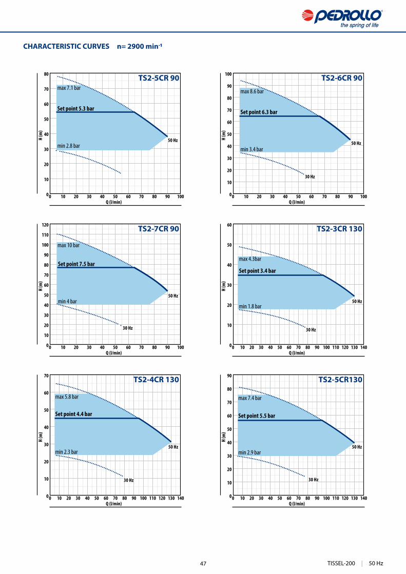
CHARACTERISTIC CURVES n= 2900 min
TISSEL-200 | 50 Hz47

146
0 10 20 30 40 50 60 70 80 90 100 110 120 130 1400
10
20
30
40
50
60
70
80
90
100
110
H (m
)
Q (l/min)
50 Hz
30 Hz
Set point 6.5 bar
min 3.5 bar
max 9.0 bar
TS2-6CR 130
0 20 40 60 80 100 120 140 160 180 200 2200
10
20
30
40
50
60
70
H (m
)
Q (l/min)
50 Hz
30 Hz
Set point 3.6 bar
min 2.1 bar
max 5.1 bar
TS2-4CR 200
0 20 40 60 80 100 120 140 160 180 200 2200
10
20
30
40
50
H (m
)
Q (l/min)
50 Hz
30 Hz
Set point 2.8 bar
min 1.6 bar
max 3.8 bar
TS2-3CR 200
0 20 40 60 80 100 120 140 160 180 200 2200
10
20
30
40
50
60
70
80H
(m)
Q (l/min)
50 Hz
30 Hz
Set point 4.6 bar
min 2.6 bar
max 6.5 bar
TS2-5CR 200
0 20 40 60 80 100 120 140 160 180 200 2200
10
20
30
40
50
60
70
80
90
100
H (m
)
Q (l/min)
50 Hz
30 Hz
Set point 5.5 bar
min 3.1 bar
max 7.9 bar
TS2-6CR 200
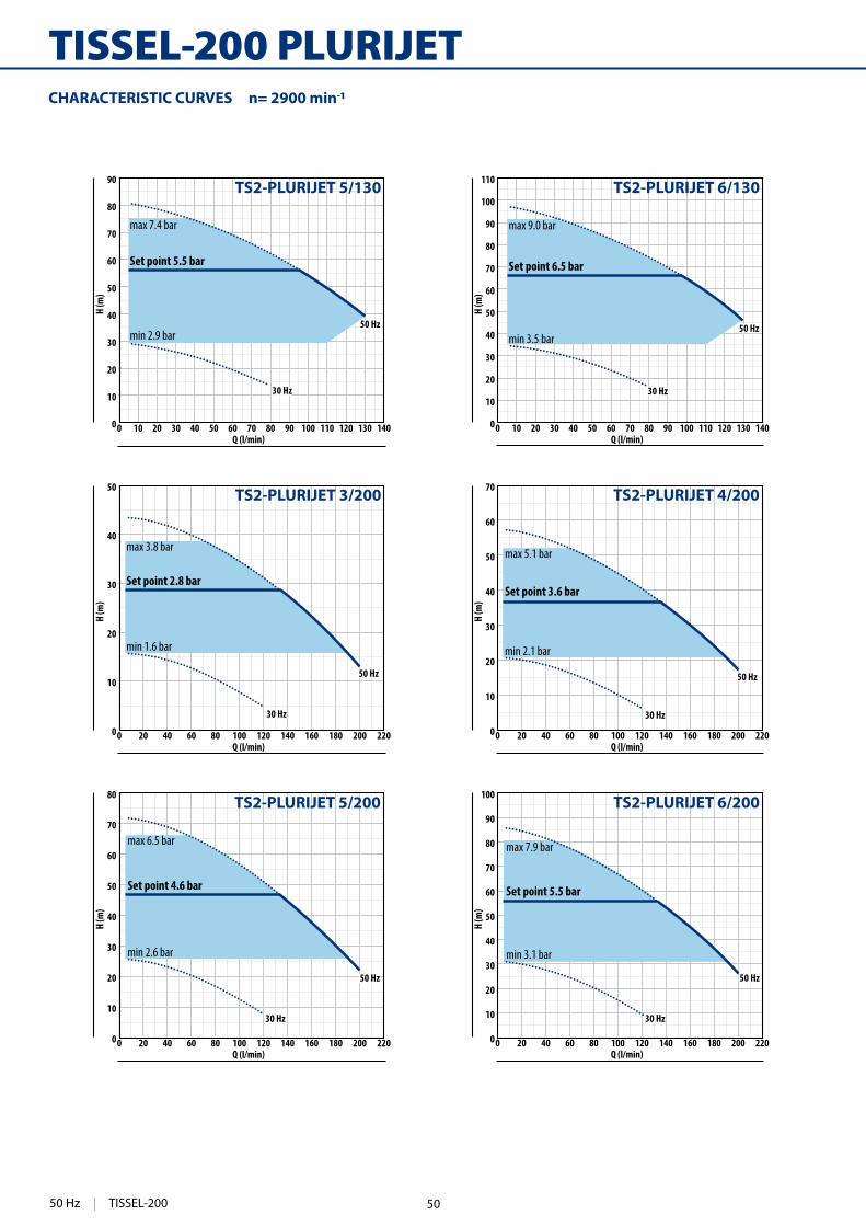
TISSEL-200 CRCHARACTERISTIC CURVES n= 2900 min
50 Hz | TISSEL-200 48

147
0 10 20 30 40 50 60 70 80 90 1000
10
20
30
40
50
60
70
80
H (m
)
Q (l/min)
50 Hz
Set point 5.3 bar
min 2.8 bar
max 7.1 barTS2-PLURIJET 5/90
0 10 20 30 40 50 60 70 80 90 100 110 120 130 1400
10
20
30
40
50
60
H (m
)
Q (l/min)
50 Hz
30 Hz
Set point 3.4 bar
min 1.8 bar
max 4.3bar
TS2-PLURIJET 3/130
0 10 20 30 40 50 60 70 80 90 1000
10
20
30
40
50
60
70
80
90
100
H (m
)
Q (l/min)
50 Hz
30 Hz
Set point 6.3 bar
min 3.4 bar
max 8.6 bar
TS2-PLURIJET 6/90
0 10 20 30 40 50 60 70 80 90 100 110 120 130 1400
10
20
30
40
50
60
70
H (m
)
Q (l/min)
50 Hz
30 Hz
Set point 4.4 bar
min 2.3 bar
max 5.8 bar
TS2-PLURIJET 4/130
TISSEL-200 PLURIJET
0
100
200
300
0 25 50 75 100 125 150 1750
10
20
30
40
50
60
70
80
90
100
110 feet
l/minm³/h0 1 2 3 4 5 6 7 8 9 10 11
0 10 20 30 40
0 10 20 30 40
US g.p.m.
Imp g.p.m.
TS2-PLURIJET 90 TS2-PLURIJET 130 TS2-PLURIJET 200
MODEL POWER ABSORPTION MAX PERFORMANCES PERFORMANCES (ADJUSTABLE SET POINT)P2 230 V Q H Min. Set Point Set Point Stand. Setting Max. Set Point
Single-phase kW HP l/min metres bar l/min bar l/min bar l/minTS2-PLURIJET 5/90 1.1 1.5
IE3
11.5 A 5 – 90 78 – 38 2.80 5 – 75 5.30 5 – 65 7.10 5 – 23TS2-PLURIJET 6/90 1.5 2 13.5 A 5 – 90 94 – 45 3.40 5 – 75 6.30 5 – 65 8.60 5 – 21TS2-PLURIJET 3/130 1.1 1.5 12.5 A 5 – 130 49 – 24 1.80 5 – 110 3.40 5 – 92 4.30 5 – 48TS2-PLURIJET 4/130 1.5 2 14.5 A 5 – 130 65 – 31 2.30 5 – 110 4.40 5 – 92 5.80 5 – 45TS2-PLURIJET 5/130 1.8 2.5 18.5 A 5 – 130 81 – 39 2.90 5 – 110 5.50 5 – 92 7.40 5 – 38TS2-PLURIJET 6/130 2.2 3 20.0 A 5 – 130 97 – 45 3.50 5 – 110 6.50 5 – 92 9.00 5 – 33TS2-PLURIJET 3/200 1.1 1.5 10.0 A 5 – 200 43 – 13 1.60 5 – 185 2.80 5 – 133 3.80 5 – 72TS2-PLURIJET 4/200 1.5 2 16.0 A 5 – 200 57 – 17 2.10 5 – 185 3.60 5 – 133 5.10 5 – 65TS2-PLURIJET 5/200 1.8 2.5 16.0 A 5 – 200 72 – 22 2.60 5 – 185 4.60 5 – 133 6.50 5 – 56TS2-PLURIJET 6/200 2.2 3 22.0 A 5 – 200 86 – 26 3.10 5 – 185 5.50 5 – 133 7.90 5 – 45
CHARACTERISTIC CURVES n= 2900 min
Flow rate Q
Hea
d H
(met
res)
CHARACTERISTIC CURVES n= 2900 min
TISSEL-200 | 50 Hz49
148
0 20 40 60 80 100 120 140 160 180 200 2200
10
20
30
40
50
H (m
)
Q (l/min)
50 Hz
30 Hz
Set point 2.8 bar
min 1.6 bar
max 3.8 bar
TS2-PLURIJET 3/200
0 20 40 60 80 100 120 140 160 180 200 2200
10
20
30
40
50
60
70
80
H (m
)
Q (l/min)
50 Hz
30 Hz
Set point 4.6 bar
min 2.6 bar
max 6.5 bar
TS2-PLURIJET 5/200
0 20 40 60 80 100 120 140 160 180 200 2200
10
20
30
40
50
60
70H
(m)
Q (l/min)
50 Hz
30 Hz
Set point 3.6 bar
min 2.1 bar
max 5.1 bar
TS2-PLURIJET 4/200
0 20 40 60 80 100 120 140 160 180 200 2200
10
20
30
40
50
60
70
80
90
100
H (m
)
Q (l/min)
50 Hz
30 Hz
Set point 5.5 bar
min 3.1 bar
max 7.9 bar
TS2-PLURIJET 6/200
0 10 20 30 40 50 60 70 80 90 100 110 120 130 1400
10
20
30
40
50
60
70
80
90
H (m
)
Q (l/min)
50 Hz
30 Hz
Set point 5.5 bar
min 2.9 bar
max 7.4 bar
TS2-PLURIJET 5/130
0 10 20 30 40 50 60 70 80 90 100 110 120 130 1400
10
20
30
40
50
60
70
80
90
100
110
H (m
)
Q (l/min)
50 Hz
30 Hz
Set point 6.5 bar
min 3.5 bar
max 9.0 bar
TS2-PLURIJET 6/130
TISSEL-200 PLURIJETCHARACTERISTIC CURVES n= 2900 min
50 Hz | TISSEL-200 50

149
1"1¼
"
24793
185143
194
14.5 9.5
h3
h141
.5
146
340
h239
330
1¼"
a173
1"
a2 185145
194330 6
11
145
56 344
DIMENSIONS (mm)
MODEL h1 h2 h3 kgTS2-MK 3/3 132.5 450 489 26.7TS2-MK 3/4 159.5 477 516 27.0TS2-MK 3/5 186.5 504 543 28.6TS2-MK 3/6 213.5 531 570 30.1TS2-MK 5/4 159.5 477 516 26.9TS2-MK 5/5 186.5 504 543 28.5TS2-MK 5/6 213.5 531 570 30.3TS2-MK 5/7 240.5 558 597 30.7TS2-MK 5/8 267.5 585 624 30.9TS2-MK 8/4 159.5 477 516 28.0TS2-MK 8/5 186.5 504 543 29.6TS2-MK 8/6 213.5 531 570 30.4
MODEL a1 a2 kgTS2-PLURIJET 5/90 245 549 27.0TS2-PLURIJET 6/90 271 575 29.0TS2-PLURIJET 3/130 193 497 25.1TS2-PLURIJET 4/130 219 523 27.1TS2-PLURIJET 5/130 245 569 30.7TS2-PLURIJET 6/130 271 595 31.8TS2-PLURIJET 3/200 193 497 25.1TS2-PLURIJET 4/200 219 523 27.1TS2-PLURIJET 5/200 245 569 30.7TS2-PLURIJET 6/200 271 595 31.8
MODEL a1 a2 kgTS2-5CR 90 193 497 26.3TS2-6CR 90 219 523 28.4TS2-7CR 90 245 569 32.5TS2-3CR 130 141 445 25.0TS2-4CR 130 167 471 26.9TS2-5CR 130 193 517 30.3TS2-6CR 130 219 543 31.2TS2-3CR 200 141 445 25.0TS2-4CR 200 167 471 26.9TS2-5CR 200 193 517 30.3TS2-6CR 200 219 543 31.2
TISSEL-200 | 50 Hz
= Stocked in Australia
Other models available upon request with 6 to 8 weeks lead time.
51

132
DG PED
AUTOMATIC PRESSURISATION SYSTEM WITH INVERTER
DESCRIPTION DG PED is an automatic pressurisation system with inverter whi-ch integrates: a high e�ciency self-priming pump; an expansion vessel; pressure and �ow rate sensors; a non-return valve.
DG PED is a compact, autonomous, quiet and high perfor-mance pumping system.
A sophisticated electronically controlled inverter, at the heart of the system, in an intuitive way:– maintains the pressure of the installation constant by regulat-
rate;– controls the hydraulic and electric operating parameters and
protects the pump from anomalies;– can be equipped with an expansion card that makes it possible
to work in parallel with other inverters in the pumping groups by managing input and output signals;
– it adapts to every type of pressurisation system, including existing ones;
– it limits the starting and operating currents in order to provide a greater saving of energy.
TECHNICAL DATA • Supply voltage ~ 230 V ± 10% • Frequency 50/60 Hz • Insulation: class F • Max absorbed current: 7.5 A DG PED 3 - 10.5 A DG PED 5 • P1 Maximum absorbed power: 1.0 kW DG PED 3 - 1.5 kW DG PED 5 • Protection IP X4 • Factory set point 3 bar
APPLICATION LIMITS • Manometric suction lift up to 8 m • Liquid temperature between 0 °C and +40 °C • Ambient temperature between 0 °C and +40 °C • Max. working pressure 10 bar • Continuous service S1 • Operates in a vertical position
Thanks to its compactness and low noise level the DG PED can be installed anywhere
LOW-NOISE
CONSTANT PRESSURE
INSTALLABLEANYWHERE
COMPACTDIMENSIONS
DOMESTIC USE
RESIDENTIAL USE
ALL IN ONE
EASY TO USE
Main components:Multistage self-priming pumpExpansion vesselNon-return valveIntuitive control panel
A single DG PED meets the requirements of single apartments or small houses.
Two DG PED assembled as a set meet the requirements of more than one apartment.
Clean water
Domestic use
Civil use
50 Hz | DG PED 52

0 10 20 30 40 50 60 70 80 900
10
20
30
40
50
60
H (m
)
Q (l/min)
DG PED 3
Set point 3 bar
max 5.5 bar
min 1 bar
0 10 20 30 40 50 60 70 80 90 100 110 120 1300
10
20
30
40
50
60
H (m
)
Q (l/min)
DG PED 5
Set point 3 bar
max 5.5 bar
min 1 bar
0 20 40 60 80 100 120 140 160 180 200 220 240 2600
10
20
30
40
50
60
min 1 bar
H (m
)
Q (l/min)
Set point 3 bar
max 5.5 bar
DG PED 3 + DG PED 3
DG PED 3 + DG PED 5
DG PED 5 + DG PED 5
360°360°
137 78 228
18066390274
160200
144
23 84
344
278
G 1
”
G 1
”18
4
CHARACTERISTIC CURVES FOR GROUPS OF TWO DG PED 3 OR 5
Q = Flow rate H = Total manometric head Tolerance of characteristic curves in compliance with EN ISO 9906 Grade 3B.
MODEL POWER MAX PERFORMANCES PERFORMANCES (ADJUSTABLE SET POINT)Q H Min. Set Point Set Point Stand. Setting Max. Set Point
Single-phase kW HP l/min metres bar l/min bar l/min bar l/min
DG PED 3 0.75 1IE3
5 – 80 55 – 10 1 35 – 80 3 5 – 58 5.5 5 – 30
DG PED 5 1.1 1.5 5 – 120 55 – 10 1 50 – 120 3 5 – 92 5.5 5 – 50
OPTIONAL ACCESSORIES
Connection kit for two DG PED units
Kit for wall-mounting a single DG PED
Kit for wall-mounting a group of two units
Electronic expansion circuit board
CHARACTERISTIC CURVES
DG PED | 50 Hz
= Stocked in Australia
Other models available upon request with 6 to 8 weeks lead time.
53

322
TOP MULTI-TECH
AUTOMATIC
START & STOP
INSTALLATION AND USETOP-MULTI-TECH pumps are recommended for pumping clean water and liquids that are not chemically aggressive for the materials from which the pump is made.Because of their high e�ciency and reliability they are suitable for use in applications such as domestic water supply from reservoirs, tanks or relatively deep wells, for drawing rain water from cisterns to water gardens or for use in irrigation systems, etc.An internal electronic device starts or stops the pump automatically when the tap is opened or closed.
PATENTS - TRADE MARKS - MODELS • Patent n. EP2990653 • TOP MULTI® Registered Trade Mark n. 0001334477
OPTIONS AVAILABLE ON REQUEST • Other voltages or 60 Hz frequency
PERFORMANCE RANGE • Flow rate up to 120 l/min (7.2 m³/h) • Head up to 42 m • Restart pressure: 1.5 bar
APPLICATION LIMITS • 5 m maximum immersion depth • Maximum height between pump and point of use 10 m • Maximum liquid temperature +40 °C • Suction down to 34 mm above ground level • Continuous service S1
CONSTRUCTION AND SAFETY STANDARDSComplete with:– 10 m long power cable– internal electronic device for pump starting (when tap opened)
and stopping (when tap closed)– threaded connector 1¼” (delivery)– hose connector Ø 35 mm
EN 60335-1IEC 60335-1CEI 61-150
EN 60034-1IEC 60034-1CEI 2-3
CERTIFICATIONS
ISO 9001: QUALITY
Multi-stage automatic submersible pumpsClean water
Civil use
Domestic use
50 Hz | TOP MULTI-TECH 54

323
0 10 20 30 40 50 60 70 80 90 100 110 1200
5
10
15
20
25
30
35
40
450 5 10 15 20 25
0 5 10 15 20 25 30
0
20
40
60
80
100
120
140
0 1 2 3 4 5 6 7
TOP MULTI-TECH 2
TOP MULTI-TECH 3
US g.p.m.
Imp g.p.m.feet
l/minm³/h
CHARACTERISTIC CURVES AND PERFORMANCE DATA 50 Hz n= 2900 min
Flow rate Q
Hea
d H
(m
etre
s)
Q = Flow rate H = Total manometric head Tolerance of characteristic curves in compliance with EN ISO 9906 Grade 3B.
MODELQ
m³/h 0 0.6 1.2 1.8 2.4 3.0 3.6 4.2 4.8 5.4 6.0 6.6 7.2
Single-phase kW HP l/min 0 10 20 30 40 50 60 70 80 90 100 110 120
TOP MULTI-TECH 2 0.55 0.75
H metres
42 40 38 34 30 24 18 11.5 5
TOP MULTI-TECH 3 0.55 0.75 33 32 31 29.5 28 25.5 23 20.5 18 15 12 8 4
TOP MULTI-TECH | 50 Hz
= Stocked in Australia
Other models available upon request with 6 to 8 weeks lead time.
55
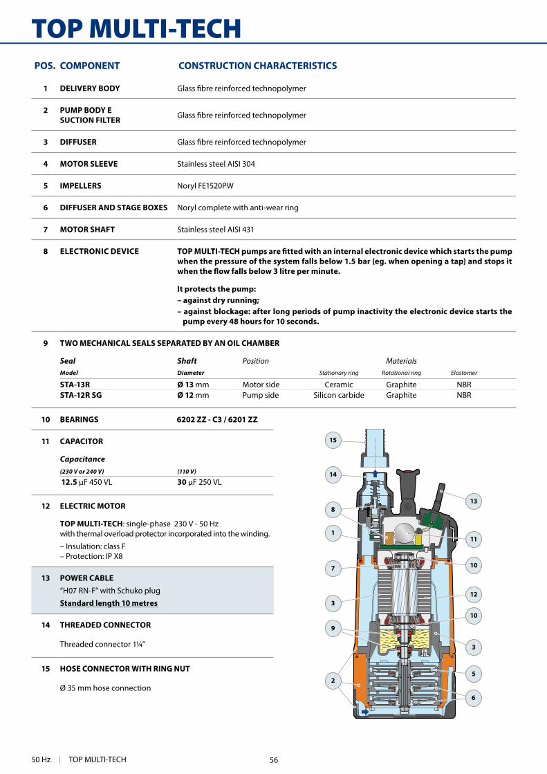
324
TOP MULTI-TECH
1
15
7
3
5
3
11
13
10
10
12
2
9
6
8
14
10 BEARINGS 6202 ZZ - C3 / 6201 ZZ
11 CAPACITOR
Capacitance(230 V or 240 V) (110 V)
12.5 30
12 ELECTRIC MOTOR
TOP MULTI-TECH: single-phase 230 V - 50 Hz with thermal overload protector incorporated into the winding.
– Insulation: class F– Protection: IP X8
13 POWER CABLE“H07 RN-F” with Schuko plug
Standard length 10 metres
14 THREADED CONNECTOR
Threaded connector 1¼”
15 HOSE CONNECTOR WITH RING NUT
Ø 35 mm hose connection
POS. COMPONENT CONSTRUCTION CHARACTERISTICS
1 DELIVERY BODY
2 PUMP BODY E SUCTION FILTER
3 DIFFUSER
4 MOTOR SLEEVE Stainless steel AISI 304
5 IMPELLERS Noryl FE1520PW
6 DIFFUSER AND STAGE BOXES Noryl complete with anti-wear ring
7 MOTOR SHAFT Stainless steel AISI 431
8 ELECTRONIC DEVICEwhen the pressure of the system falls below 1.5 bar (eg. when opening a tap) and stops it
It protects the pump:– against dry running;– against blockage: after long periods of pump inactivity the electronic device starts the
pump every 48 hours for 10 seconds.
9 TWO MECHANICAL SEALS SEPARATED BY AN OIL CHAMBER
Seal Shaft Position MaterialsModel Diameter Stationary ring Rotational ring Elastomer
STA-13R Ø 13 mm Motor side Ceramic Graphite NBRSTA-12R SG Ø 12 mm Pump side Silicon carbide Graphite NBR
50 Hz | TOP MULTI-TECH 56

325
1SFNT
DN
h
a
DIMENSIONS AND WEIGHTStandard installation
min
imum
500
mm
MODEL GROUPAGE CONTAINER
Single-phase n. pumps n. pumps
TOP MULTI-TECH 2 60 80
TOP MULTI-TECH 3 60 80
To operate correctly avoiding frequent restarts and for greater energy saving it is necessary to install the 1 SF tank (or a similar tank with a minimum capacity of 1 litre) with an initial load of 1.2 bar
Max
imum
del
iver
y he
ight
10
m
ABSORPTION
MODEL VOLTAGE
Single-phase 230 V
TOP MULTI-TECH 2 3.4 A
TOP MULTI-TECH 3 3.6 A
MODEL PORT N. STAGES
DIMENSIONS mm
kg
Single-phase DN a h
TOP MULTI-TECH 21¼" 3 178 428 9.3
TOP MULTI-TECH 3
PALLETIZATION
22 mm minimum 300 mm
ACCESSORIES (CAN BE ORDERED SEPARATELY)
MODEL Code FITTING CAPACITY PRE-SET MAXIMUM WORKING PRESSURE
Tank 1 SF 500667 ½" (male) 1 litre 1.2 bar 10 bar
NT 1.25 500160001 1¼"- 1¼" - ½" gas – – –
TOP MULTI-TECH | 50 Hz57

306
NKMulti-stage submersible pumps
INSTALLATION AND USE
use with clean water in domestic, civil and agricultural applications such as the distribution of water in combination with pressure tanks, for the irrigation of gardens and orchards and for pressure boosting, etc.
PATENTS - TRADE MARKS - MODELS • Patent n. EP14755156.8 • Patent n. EP2313658
OPTIONS AVAILABLE ON REQUEST • • • Other voltages or 60 Hz frequency
PERFORMANCE RANGE • Flow rate up to 160 l/min (7.2 m³/h) • Head up to 95 m
APPLICATION LIMITS • Maximum liquid temperature +40 °C • Maximum sand content 150 g/m³ • 20 m maximum immersion depth
• Continuous service S1
CONSTRUCTION AND SAFETY STANDARDS 10 m long power cable Float switch for single-phase versions
EN 60335-1IEC 60335-1CEI 61-150
EN 60034-1IEC 60034-1CEI 2-3
CERTIFICATIONS
ISO 9001: QUALITY
Civil use
Agricultural use
Domestic use
Clean water(Maximum sand content 150 g/m³)
50 Hz | NK 58

307
0 10 20 30 40 50 60 70 80 90 100 110 120 130 140 150 1600
10
20
30
40
50
60
70
80
90
100
0
50
100
150
200
250
300
0 10 20 30 40
0 10 20 30
0 1 2 3 4 5 6 7 8 9
US g.p.m.
Imp g.p.m.feet
l/minm³/h
NK2/3
NK2/2
NK2/4
NK2/5
NK2/6
NK4/6
NK4/5
NK4/4
NK4/3
NK8/4
NK8/3
CHARACTERISTIC CURVES AND PERFORMANCE DATA 50 Hz n= 2900 min
Flow rate Q
Hea
d H
(m
etre
s)
MODELQ
m³/h 0 0.6 1.2 1.8 2.4 3.0 3.6 4.2 4.8 6.0 6.6 7.2 8.4 9.6
Single-phase Three-phase kW HP l/min 0 10 20 30 40 50 60 70 80 100 110 120 140 160
NKm 2/2 GE NK 2/2 0.37 0.5
H metres
33 32 31 29.5 28 26 23.5 20.5 17
NKm 2/3 GE NK 2/3 0.55 0.75 48 46 44.5 42.8 40.5 37.5 33.5 29 23
NKm 2/4 GE NK 2/4 0.75 1 63 61 59 57 54 50 45 39 31
NKm 2/5 GE NK 2/5 1.1 1.5 81 79 75.5 73 68.5 63.5 57.5 49.5 40
NKm 2/6 GE NK 2/6 1.5 2 95 93 90 87 82 76 68.5 59.5 48
NKm 4/3 GE NK 4/3 0.55 0.75 40 – 39 38 37 35 33 30.5 28 20.5 16.5 12
NKm 4/4 GE NK 4/4 0.75 1 53 – 52 50.5 49 46.5 44 40.5 37 27.5 22 16
NKm 4/5 GE NK 4/5 1.1 1.5 67 – 65 63.5 61.5 58 55 50.5 46.5 34 27.5 20
NKm 4/6 GE NK 4/6 1.5 2 80 – 78 76 74 70 66 61 56 41 33 24
NKm 8/3 GE NK 8/3 1.1 1.5 40 – – – 39 38 37.5 36.5 35 32 30 28 22.5 16
NKm 8/4 GE NK 8/4 1.5 2 52 – – – 51 50 49 48 46 42 39 36 29 21
Q = Flow rate H = Total manometric head Tolerance of characteristic curves in compliance with EN ISO 9906 Grade 3B.
➠
NK | 50 Hz
= Stocked in Australia
Other models available upon request with 6 to 8 weeks lead time.
59

308
NK
1
11
8
10
8
14
3
6
5
4
7
9
12
13
2
8 BEARINGS 6303 2RS - C3 / 6203 ZZ - C3E
9 CAPACITOR
Pump CapacitanceSingle-phase (230 V or 240 V) (110 V)
NKm 2/2 GENKm 2/3 GENKm 4/3 GE
16 30
NKm 2/4 GENKm 4/4 GE 20 –
NKm 2/5 GENKm 4/5 GENKm 8/3 GE
25 –
NKm 2/6 GENKm 4/6 GENKm 8/4 GE
35 –
10 ELECTRIC MOTOR
NKm: single-phase 230 V - 50 Hz with thermal overload protector incorporated into the winding.
NK: three-phase 400 V - 50 Hz.
– Insulation: class F – Protection: IP X8
11 POWER CABLE
➠ DRINCABLE® type approved for use in drinking water by "WRAS" in compliance with BS 6920, approval n. 7513 Standard length 10 metres
12 AUTOMATIC VENT VALVE
13 ANTI-VIBRATION SUPPORTS
14 FLOAT SWITCH(only for single-phase versions)
POS. COMPONENT CONSTRUCTION CHARACTERISTICS
1 EXTERNAL SLEEVE Stainless steel AISI 304 complete with threaded delivery port in compliance with ISO 228/1
2 SUCTION FILTER Stainless steel AISI 304 complete with anti-vibration supports
3 MOTOR SLEEVE Stainless steel AISI 304
4 IMPELLERS AND DIFFUSERS Noryl FE1520PW
5 DIAPHRAGMS Stainless steel AISI 304
6 MOTOR SHAFT Stainless steel AISI 431
7 TWO MECHANICAL SEALS SEPARATED BY AN OIL CHAMBER
Seal Shaft Position MaterialsModel Diameter Stationary ring Rotational ring Elastomer
STA-17 Ø 17 mm Motor side Ceramic Graphite NBRST1-16 Ø 16 mm Pump side Silicon carbide Graphite NBR
50 Hz | NK 60

309
Ø
DN
h
DIMENSIONS AND WEIGHT
ABSORPTION
MODEL PORT N.STAGES
DIMENSIONS mm kg
Single-phase Three-phase DN Ø h 1~ 3~
NKm 2/2 GE NK 2/2
1¼"
2
135
459 13.0 13.0
NKm 2/3 GE NK 2/3 3 486 13.4 13.4
NKm 2/4 GE NK 2/4 4 543 15.6 14.2
NKm 2/5 GE NK 2/5 5 570 15.6 15.4
NKm 2/6 GE NK 2/6 6 617 18.6 17.2
NKm 4/3 GE NK 4/3 3 486 13.4 13.4
NKm 4/4 GE NK 4/4 4 543 15.2 14.0
NKm 4/5 GE NK 4/5 5 570 16.5 15.5
NKm 4/6 GE NK 4/6 6 617 18.4 17.0
NKm 8/3 GE NK 8/3 3 516 15.5 14.4
NKm 8/4 GE NK 8/4 4 563 17.6 15.9
MODEL VOLTAGE
Single-phase 230 V 240 V 110 V
NKm 2/2 GE 4.3 A 3.9 A 8.6 A
NKm 2/3 GE 5.5 A 4.8 A 11.0 A
NKm 2/4 GE 6.2 A 5.9 A –
NKm 2/5 GE 7.6 A 7.6 A –
NKm 2/6 GE 9.2 A 9.0 A –
NKm 4/3 GE 5.0 A 4.8 A 10.0 A
NKm 4/4 GE 6.2 A 5.9 A –
NKm 4/5 GE 7.5 A 6.9 A –
NKm 4/6 GE 8.7 A 8.4 A –
NKm 8/3 GE 7.1 A 6.8 A –
NKm 8/4 GE 9.2 A 9.0 A –
MODEL VOLTAGE
Three-phase 230 V 400 V 240 V 415 V
NK 2/2 2.8 A 1.6 A 2.7 A 1.5 A
NK 2/3 3.3 A 1.9 A 3.2 A 1.8 A
NK 2/4 4.0 A 2.3 A 3.9 A 2.2 A
NK 2/5 5.2 A 3.0 A 4.9 A 2.8 A
NK 2/6 5.9 A 3.4 A 5.5 A 3.2 A
NK 4/3 3.2 A 1.8 A 3.1 A 1.7 A
NK 4/4 3.8 A 2.2 A 3.7 A 2.1 A
NK 4/5 4.8 A 2.8 A 4.7 A 2.7 A
NK 4/6 5.5 A 3.2 A 5.4 A 3.1 A
NK 8/3 5.0 A 2.9 A 4.7 A 2.7 A
NK 8/4 5.9 A 3.4 A 5.4 A 3.1 A
MODEL GROUPAGE CONTAINER
Single-phase Three-phase n. pumps n. pumps
NKm 2/2 GE NK 2/2 30 54
NKm 2/3 GE NK 2/3 30 54
NKm 2/4 GE NK 2/4 25 45
NKm 2/5 GE NK 2/5 25 45
NKm 2/6 GE NK 2/6 25 45
NKm 4/3 GE NK 4/3 30 54
NKm 4/4 GE NK 4/4 25 45
NKm 4/5 GE NK 4/5 25 45
NKm 4/6 GE NK 4/6 25 45
NKm 8/3 GE NK 8/3 30 –
NKm 8/4 GE NK 8/4 25 45
PALLETIZATION
NK | 50 Hz61
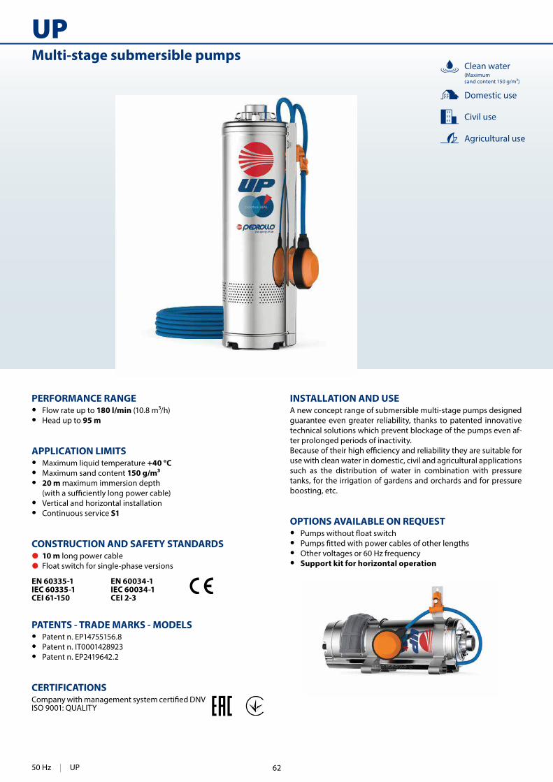
302
UPMulti-stage submersible pumps
INSTALLATION AND USEA new concept range of submersible multi-stage pumps designed guarantee even greater reliability, thanks to patented innovative technical solutions which prevent blockage of the pumps even af-ter prolonged periods of inactivity.
use with clean water in domestic, civil and agricultural applications such as the distribution of water in combination with pressure tanks, for the irrigation of gardens and orchards and for pressure boosting, etc.
OPTIONS AVAILABLE ON REQUEST • • • Other voltages or 60 Hz frequency • Support kit for horizontal operation
PERFORMANCE RANGE • Flow rate up to 180 l/min (10.8 m³/h) • Head up to 95 m
APPLICATION LIMITS • Maximum liquid temperature +40 °C • Maximum sand content 150 g/m³ • 20 m maximum immersion depth
• Vertical and horizontal installation • Continuous service S1
CONSTRUCTION AND SAFETY STANDARDS 10 m long power cable Float switch for single-phase versions
EN 60335-1IEC 60335-1CEI 61-150
EN 60034-1IEC 60034-1CEI 2-3
PATENTS - TRADE MARKS - MODELS • Patent n. EP14755156.8 • Patent n. IT0001428923 • Patent n. EP2419642.2
CERTIFICATIONS
ISO 9001: QUALITY
Civil use
Agricultural use
Domestic use
Clean water(Maximum sand content 150 g/m³)
50 Hz | UP 62
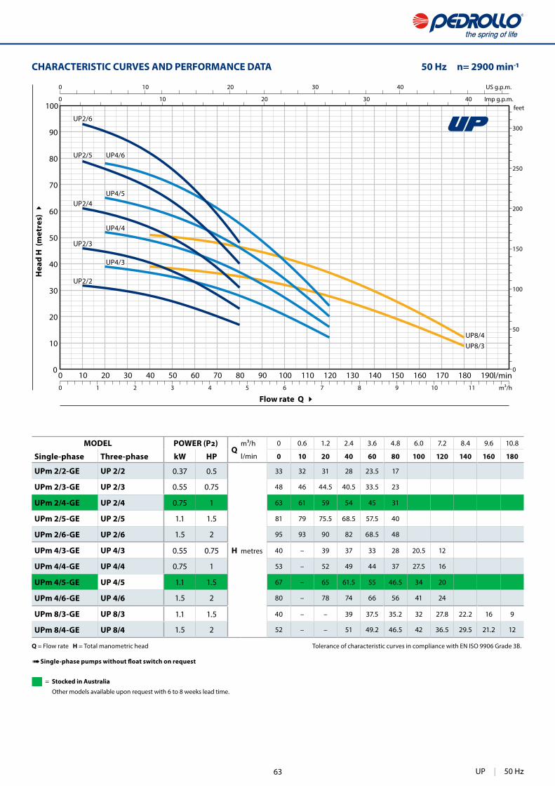
303
0 10 20 30 40 50 60 70 80 90 100 110 120 130 140 150 160 170 180 1900
10
20
30
40
50
60
70
80
90
100
0
50
100
150
200
250
300
0 10 20 30 40
0 10 20 30 40
0 1 2 3 4 5 6 7 8 9 10 11
UP2/3
UP2/2
UP2/4
UP2/5
UP2/6
UP4/6
UP4/5
UP4/4
UP4/3
UP8/3UP8/4
US g.p.m.
Imp g.p.m.feet
l/minm³/h
CHARACTERISTIC CURVES AND PERFORMANCE DATA 50 Hz n= 2900 min
Flow rate Q
Hea
d H
(m
etre
s)
Q = Flow rate H = Total manometric head Tolerance of characteristic curves in compliance with EN ISO 9906 Grade 3B.
➠
MODELQ
m³/h 0 0.6 1.2 2.4 3.6 4.8 6.0 7.2 8.4 9.6 10.8
Single-phase Three-phase kW HP l/min 0 10 20 40 60 80 100 120 140 160 180
UPm 2/2-GE UP 2/2 0.37 0.5
H metres
33 32 31 28 23.5 17
UPm 2/3-GE UP 2/3 0.55 0.75 48 46 44.5 40.5 33.5 23
UPm 2/4-GE UP 2/4 0.75 1 63 61 59 54 45 31
UPm 2/5-GE UP 2/5 1.1 1.5 81 79 75.5 68.5 57.5 40
UPm 2/6-GE UP 2/6 1.5 2 95 93 90 82 68.5 48
UPm 4/3-GE UP 4/3 0.55 0.75 40 – 39 37 33 28 20.5 12
UPm 4/4-GE UP 4/4 0.75 1 53 – 52 49 44 37 27.5 16
UPm 4/5-GE UP 4/5 1.1 1.5 67 – 65 61.5 55 46.5 34 20
UPm 4/6-GE UP 4/6 1.5 2 80 – 78 74 66 56 41 24
UPm 8/3-GE UP 8/3 1.1 1.5 40 – – 39 37.5 35.2 32 27.8 22.2 16 9
UPm 8/4-GE UP 8/4 1.5 2 52 – – 51 49.2 46.5 42 36.5 29.5 21.2 12
UP | 50 Hz
= Stocked in Australia
Other models available upon request with 6 to 8 weeks lead time.
63

304
UP
10
13
1
4
2
8
12
5
7
7
9
3
6
11
7 BEARINGS 6303 2RS - C3 / 6203 ZZ - C3E
8 CAPACITOR
Pump CapacitanceSingle-phase (230 V or 240 V) (110 V)
UPm 2/2-GEUPm 2/3-GEUPm 4/3-GE
16 30
UPm 2/4-GEUPm 4/4-GE 20 –
UPm 2/5-GEUPm 4/5-GEUPm 8/3-GE
25 –
UPm 2/6-GEUPm 4/6-GEUPm 8/4-GE
35 –
9 ELECTRIC MOTOR
UPm: single-phase 230 V - 50 Hz with thermal overload protector incorporated into the winding.
UP: three-phase 400 V - 50 Hz.
– Insulation: class F – Protection: IP X8
10 POWER CABLE
➠ DRINCABLE® type approved for use in drinking water by "WRAS" in compliance with BS 6920, approval n. 7513 Standard length 10 metres
11 AUTOMATIC VENT VALVE
12 ANTI-VIBRATION SUPPORTS
13 FLOAT SWITCH(only for single-phase versions)
POS. COMPONENT CONSTRUCTION CHARACTERISTICS
1 EXTERNAL SLEEVE Stainless steel AISI 304 complete with threaded delivery port in compliance with ISO 228/1
2 MOTOR SLEEVE Stainless steel AISI 304
3 IMPELLERS AND DIFFUSERS Noryl FE1520PW
4 DIAPHRAGMS Stainless steel AISI 304
5 MOTOR SHAFT Stainless steel AISI 431
6 TWO MECHANICAL SEALS SEPARATED BY AN OIL CHAMBER
Seal Shaft Position MaterialsModel Diameter Stationary ring Rotational ring Elastomer
STA-17 Ø 17 mm Motor side Ceramic Graphite NBRST1-16 Ø 16 mm Pump side Silicon carbide Graphite NBR
50 Hz | UP 64
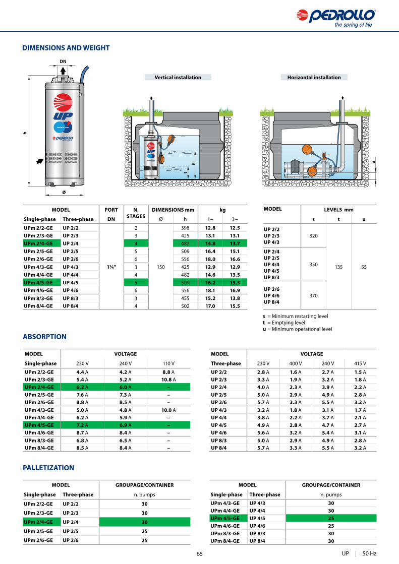
305
t
s u
h
Ø
DN
DIMENSIONS AND WEIGHT
PALLETIZATION
Vertical installation Horizontal installation
ABSORPTION
MODEL PORT N.STAGES
DIMENSIONS mm kg
Single-phase Three-phase DN Ø h 1~ 3~
UPm 2/2-GE UP 2/2
1¼"
2
150
398 12.8 12.5UPm 2/3-GE UP 2/3 3 425 13.1 13.1UPm 2/4-GE UP 2/4 4 482 14.8 13.7UPm 2/5-GE UP 2/5 5 509 16.4 15.1UPm 2/6-GE UP 2/6 6 556 18.0 16.6UPm 4/3-GE UP 4/3 3 425 12.9 12.9UPm 4/4-GE UP 4/4 4 482 14.6 13.5UPm 4/5-GE UP 4/5 5 509 16.2 15.3UPm 4/6-GE UP 4/6 6 556 18.1 16.9UPm 8/3-GE UP 8/3 3 455 15.2 13.8UPm 8/4-GE UP 8/4 4 502 17.0 15.5
MODEL LEVELS mm
s t u
UP 2/2 UP 2/3UP 4/3
320
135 55
UP 2/4UP 2/5UP 4/4UP 4/5UP 8/3
350
UP 2/6UP 4/6UP 8/4
370
MODEL VOLTAGE
Single-phase 230 V 240 V 110 V
UPm 2/2-GE 4.4 A 4.2 A 8.8 A UPm 2/3-GE 5.4 A 5.2 A 10.8 A UPm 2/4-GE 6.2 A 6.0 A –UPm 2/5-GE 7.6 A 7.3 A –UPm 2/6-GE 8.8 A 8.5 A –UPm 4/3-GE 5.0 A 4.8 A 10.0 A UPm 4/4-GE 6.2 A 5.9 A –UPm 4/5-GE 7.2 A 6.9 A –UPm 4/6-GE 8.7 A 8.4 A –UPm 8/3-GE 6.8 A 6.5 A –UPm 8/4-GE 8.5 A 8.4 A –
MODEL VOLTAGE
Three-phase 230 V 400 V 240 V 415 V
UP 2/2 2.8 A 1.6 A 2.7 A 1.5 AUP 2/3 3.3 A 1.9 A 3.2 A 1.8 AUP 2/4 4.0 A 2.3 A 3.9 A 2.2 AUP 2/5 5.0 A 2.9 A 4.9 A 2.8 AUP 2/6 5.7 A 3.3 A 5.5 A 3.2 AUP 4/3 3.2 A 1.8 A 3.1 A 1.7 AUP 4/4 3.8 A 2.2 A 3.7 A 2.1 AUP 4/5 4.9 A 2.8 A 4.7 A 2.7 AUP 4/6 5.6 A 3.2 A 5.4 A 3.1 AUP 8/3 5.0 A 2.9 A 4.9 A 2.8 AUP 8/4 5.7 A 3.3 A 5.5 A 3.2 A
s = Minimum restarting level t = Emptying levelu = Minimum operational level
MODEL GROUPAGE/CONTAINER
Single-phase Three-phase n. pumps
UPm 2/2-GE UP 2/2 30
UPm 2/3-GE UP 2/3 30
UPm 2/4-GE UP 2/4 30
UPm 2/5-GE UP 2/5 25
UPm 2/6-GE UP 2/6 25
MODEL GROUPAGE/CONTAINER
Single-phase Three-phase n. pumps
UPm 4/3-GE UP 4/3 30UPm 4/4-GE UP 4/4 30UPm 4/5-GE UP 4/5 25UPm 4/6-GE UP 4/6 25UPm 8/3-GE UP 8/3 30UPm 8/4-GE UP 8/4 30
UP | 50 Hz65

310
TOP MULTI
TOP MULTI 1
TOP MULTI 2TOP MULTI 3
INSTALLATION AND USETOP MULTI® pumps are recommended for pumping clean water and liquids that are not chemically aggressive for the materials from which the pump is made.
use in applications such as domestic water supply from reservoirs, tanks or relatively deep wells, for drawing rain water from cisterns to water gardens or for use in irrigation systems, etc.
PATENTS - TRADE MARKS - MODELS • Registered EU Design n. 000885587 for TOP MULTI 2-3 • TOP MULTI® Registered Trade Mark n. 0001334477
OPTIONS AVAILABLE ON REQUEST • • Other voltages or 60 Hz frequency
PERFORMANCE RANGE • Flow rate up to 120 l/min (7.2 m³/h) • Head up to 42 m
APPLICATION LIMITS • Immersion depth:
– up to 3 m for TOP MULTI 1– up to 10 m for TOP MULTI 2-3
• Maximum liquid temperature +40 °C • Suction level:
– 25 mm above ground level for TOP MULTI 1– 35 mm above ground level for TOP MULTI 2-3
• Continuous service S1
CONSTRUCTION AND SAFETY STANDARDSComplete with:– 10 m long power cable
– hose connector Ø 35 mm
EN 60335-1IEC 60335-1CEI 61-150
EN 60034-1IEC 60034-1CEI 2-3
CERTIFICATIONS
ISO 9001: QUALITY
Submersible multi-stage pumps Clean water
Civil use
Domestic use
50 Hz | TOP MULTI 66
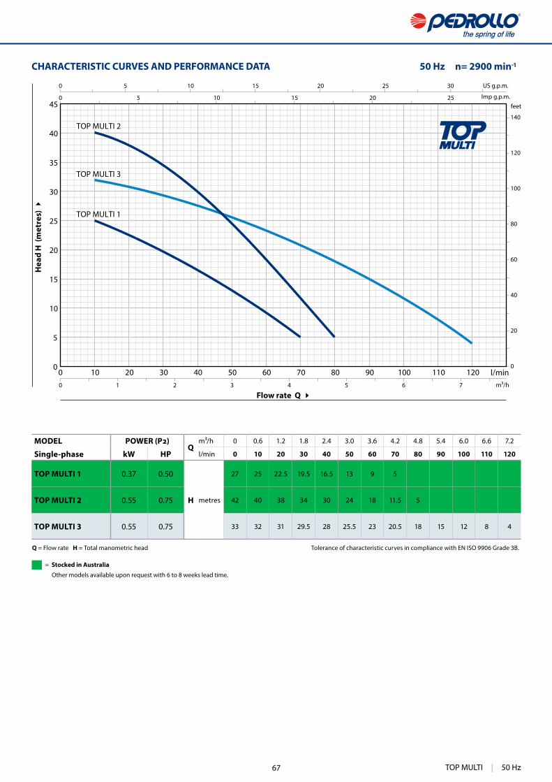
311
0 10 20 30 40 50 60 70 80 90 100 110 1200
5
10
15
20
25
30
35
40
450 5 10 15 20 25
0 5 10 15 20 25 30
0
20
40
60
80
100
120
140
0 1 2 3 4 5 6 7
TOP MULTI 2
TOP MULTI 1
TOP MULTI 3
US g.p.m.
Imp g.p.m.feet
l/minm³/h
Flow rate Q
Hea
d H
(m
etre
s)
CHARACTERISTIC CURVES AND PERFORMANCE DATA 50 Hz n= 2900 min
Q = Flow rate H = Total manometric head Tolerance of characteristic curves in compliance with EN ISO 9906 Grade 3B.
MODELQ
m³/h 0 0.6 1.2 1.8 2.4 3.0 3.6 4.2 4.8 5.4 6.0 6.6 7.2
Single-phase kW HP l/min 0 10 20 30 40 50 60 70 80 90 100 110 120
TOP MULTI 1 0.37 0.50
H metres
27 25 22.5 19.5 16.5 13 9 5
TOP MULTI 2 0.55 0.75 42 40 38 34 30 24 18 11.5 5
TOP MULTI 3 0.55 0.75 33 32 31 29.5 28 25.5 23 20.5 18 15 12 8 4
TOP MULTI | 50 Hz
= Stocked in Australia
Other models available upon request with 6 to 8 weeks lead time.
67
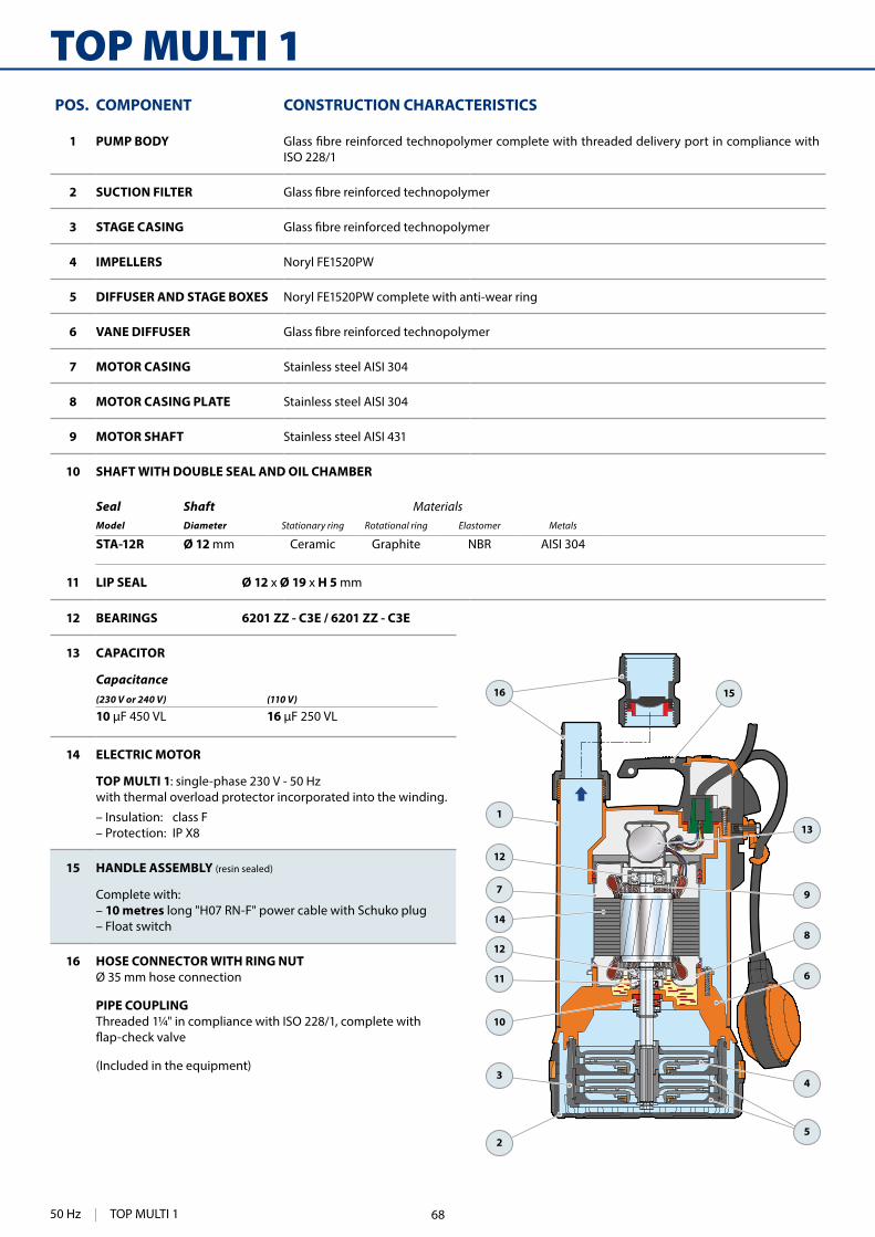
312
TOP MULTI 1
1
15
2
4
5
6
8
9
13
12
12
14
11
10
3
7
16
12 BEARINGS 6201 ZZ - C3E / 6201 ZZ - C3E
13 CAPACITOR
Capacitance(230 V or 240 V) (110 V)
10 16
14 ELECTRIC MOTOR
TOP MULTI 1: single-phase 230 V - 50 Hz with thermal overload protector incorporated into the winding.
– Insulation: class F– Protection: IP X8
15 HANDLE ASSEMBLY (resin sealed)
Complete with: – 10 metres long "H07 RN-F" power cable with Schuko plug– Float switch
16 HOSE CONNECTOR WITH RING NUTØ 35 mm hose connection
PIPE COUPLINGThreaded 1¼" in compliance with ISO 228/1, complete with
(Included in the equipment)
POS. COMPONENT CONSTRUCTION CHARACTERISTICS
1 PUMP BODYISO 228/1
2 SUCTION FILTER
3 STAGE CASING
4 IMPELLERS Noryl FE1520PW
5 DIFFUSER AND STAGE BOXES Noryl FE1520PW complete with anti-wear ring
6 VANE DIFFUSER
7 MOTOR CASING Stainless steel AISI 304
8 MOTOR CASING PLATE Stainless steel AISI 304
9 MOTOR SHAFT Stainless steel AISI 431
10 SHAFT WITH DOUBLE SEAL AND OIL CHAMBER
Seal Shaft MaterialsModel Diameter Stationary ring Rotational ring Elastomer Metals
STA-12R Ø 12 mm Ceramic Graphite NBR AISI 304
11 LIP SEAL Ø 12 x Ø 19 x H 5 mm
50 Hz | TOP MULTI 1 68
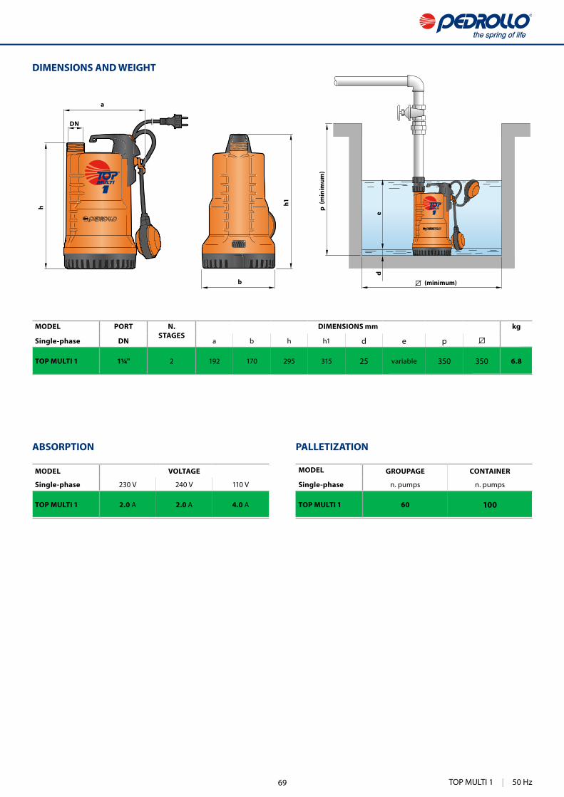
313
DN
b
a
h
de
h1
DIMENSIONS AND WEIGHT
p (m
inim
um)
(minimum)
ABSORPTION
MODEL VOLTAGE
Single-phase 230 V 240 V 110 V
TOP MULTI 1 2.0 A 2.0 A 4.0 A
MODEL PORT N. STAGES
DIMENSIONS mm kg
Single-phase DN a b h h1 d e p
TOP MULTI 1 1¼" 2 192 170 295 315 25 variable 350 350 6.8
PALLETIZATION
MODEL GROUPAGE CONTAINER
Single-phase n. pumps n. pumps
TOP MULTI 1 60 100
TOP MULTI 1 | 50 Hz69
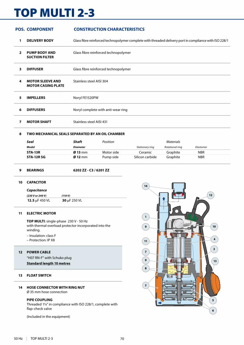
314
TOP MULTI 2-3
10
3
5
13
1
12
11
2
6
8
7
9
9
14
4
9 BEARINGS 6202 ZZ - C3 / 6201 ZZ
10 CAPACITOR
Capacitance(230 V or 240 V) (110 V)
12.5 30
11 ELECTRIC MOTOR
TOP MULTI: single-phase 230 V - 50 Hz with thermal overload protector incorporated into the winding.
– Insulation: class F – Protection: IP X8
12 POWER CABLE“H07 RN-F” with Schuko plug
Standard length 10 metres
13 FLOAT SWITCH
14 HOSE CONNECTOR WITH RING NUTØ 35 mm hose connection
PIPE COUPLINGThreaded 1¼” in compliance with ISO 228/1, complete with
(Included in the equipment)
POS. COMPONENT CONSTRUCTION CHARACTERISTICS
1 DELIVERY BODY
2 PUMP BODY ANDSUCTION FILTER
3 DIFFUSER
4 MOTOR SLEEVE ANDMOTOR CASING PLATE
Stainless steel AISI 304
5 IMPELLERS Noryl FE1520PW
6 DIFFUSERS Noryl complete with anti-wear ring
7 MOTOR SHAFT Stainless steel AISI 431
8 TWO MECHANICAL SEALS SEPARATED BY AN OIL CHAMBER
Seal Shaft Position MaterialsModel Diameter Stationary ring Rotational ring Elastomer
STA-13R Ø 13 mm Motor side Ceramic Graphite NBRSTA-12R SG Ø 12 mm Pump side Silicon carbide Graphite NBR
50 Hz | TOP MULTI 2-3 70

315
DIMENSIONS AND WEIGHTStandard installation
ABSORPTION
MODEL VOLTAGE
Single-phase 230 V 240 V 110 V
TOP MULTI 2 3.4 A 3.3 A 6.6 A
TOP MULTI 3 3.6 A 3.5 A 7.2 A
MODEL PORT N.STAGES
DIMENSIONS mm
kg
Single-phase DN a h
TOP MULTI 21¼" 3 178 380
9.2
TOP MULTI 3 9.3
MODEL GROUPAGE CONTAINER
Single-phase n. pumps n. pumps
TOP MULTI 2 60 80
TOP MULTI 3 60 80
PALLETIZATION
TOP MULTI 2-3 | 50 Hz71

248
4BLOCK4" monoblock submersible pumps
PERFORMANCE RANGE • Flow rate up to 200 l/min (12 m³/h) • Head up to 128 m
APPLICATION LIMITS • Maximum liquid temperature +35 °C • Maximum sand content 150 g/m³ • Maximum immersion depth of 60 m
power cable • Vertical and horizontal installation • Starts/hour: 20 at regular intervals • Continuous service S1
CONSTRUCTION AND SAFETY STANDARDSEN 60335-1IEC 60335-1CEI 61-150
EN 60034-1IEC 60034-1CEI 2-3
EU REGULATION N. 547/2012
CERTIFICATIONS
ISO 9001: QUALITY
INSTALLATION AND USESuitable for pumping clean water from boreholes that contain sand (up to 150 g/m ).
use in domestic applications such as domestic water supply as part of a pressure supply and for irrigation, etc.
PATENTS - TRADE MARKS - MODELS • Patent n. EP2300717 - EP2419642
OPTIONS AVAILABLE ON REQUEST • 30 metres long power cable • Other voltages or 60 Hz frequency
➠ Ready to install, stainless steel monoblock submersible pump.Complete with: – motor with built-in capacitor and thermal overload protector – 20 m long power cable.
Civil use
Agricultural use
Domestic use
Clean water(Maximum sand content 150 g/m³)
50 Hz | 4BLOCK 72

249
0 25 50 75 100 125 150 175 2000
10
20
30
40
50
60
70
80
90
100
110
120
130
6/9
6/6
6/48/7
8/4
2/20
2/13
2/10
0
100
200
300
400
0 10 20 30 40 50
0 10 20 30 40
US g.p.m.
Imp g.p.m.feet
0 1 2 3 4 5 6 7 8 9 10 11 12 13
l/minm³/h
4/14
4/9
4/7
η = 48%
η = 55%
η = 62%
η = 60%
MEI≥ 0.40
Flow rate Q
Hea
d H
(m
etre
s)
CHARACTERISTIC CURVES AND PERFORMANCE DATA 50 Hz n= 2900 min
Q = Flow rate H = Total manometric head Tolerance of characteristic curves in compliance with EN ISO 9906 Grade 3B.
MODELQ
m³/h 0 0.6 1.2 1.5 2.4 3.6 4.5 6.0 7.5 9.0 10.5 12.0
Single-phase kW HP l/min 0 10 20 25 40 60 75 100 125 150 175 200
4BLOCKm 2/10 0.55 0.75
H metres
66 65 60 57 46 20
4BLOCKm 2/13 0.75 1 86 85 79 75 60 26
4BLOCKm 2/20 1.1 1.5 128 125 118 113 91 39
4BLOCKm 4/7 0.55 0.75 46 – 44 43 40 35 29.5 17
4BLOCKm 4/9 0.75 1 60 – 56 55 52 45 37.5 23
4BLOCKm 4/14 1.1 1.5 92 – 88 87 81 70 58 35
4BLOCKm 6/4 0.55 0.75 28 – – 26 25 23.5 22 19 15 11
4BLOCKm 6/6 0.75 1 40 – – 38 37 35 33 29 24 17
4BLOCKm 6/9 1.1 1.5 61 – – 58 56 52.5 50 44 35 26
4BLOCKm 8/4 0.75 1 26.5 – – – 26 25 24 22 19.5 16.2 12.5 7.5
4BLOCKm 8/7 1.1 1.5 46 – – – 45 44 42 39 34 28.5 21.5 13
4BLOCK | 50 Hz
= Stocked in Australia
Other models available upon request with 6 to 8 weeks lead time.73

250
4BLOCK
1
10
12
5
7
6
8
15
9
12
14
13
4
2
3
11
POS. COMPONENT CONSTRUCTION CHARACTERISTICS
1 DELIVERY BODY AND EXTERNAL SLEEVE
Stainless steel AISI 304 complete with thread-ed delivery port in compliance with ISO 228/1.
2 IMPELLERS Lexan 141-R
3 DIFFUSERS Noryl FE1520PW
4 STAGE CASING Stainless steel AISI 304
5 PUMP SHAFT Stainless steel AISI 304
6 PUMP BEARINGS Special technopolymer housing with stainless steel AISI 316, chrome oxide coated, sand re-sistant shaft bushing.
7 DRIVE COUPLING Stainless steel AISI 316L
8 CABLE COVER Stainless steel AISI 304
9 MOTOR SHAFT Stainless steel AISI 431
10 MOTOR SLEEVE Stainless steel AISI 304
11 TWO MECHANICAL SEALS SEPARATED BY AN OIL CHAMBER
Seal Shaft Position MaterialsModel Diameter Stationary ring Rotational ring Elastomer
STA-17 Ø 17 mm Motor side Ceramic Graphite NBR
ST1-16 Ø 16 mm Pump side Silicon carbide Graphite NBR
12 BEARINGS
Pump Model4BLOCK – 0.55–0.75 kW 6203 2RS - C3E / 6203 ZZ - C3E4BLOCK – 1.1 kW 3203B 2RS - C3 / 6203 ZZ - C3E
13 CAPACITOR
Pump CapacitanceSingle-phase (230 V or 240 V)
4BLOCK – 0.55 kW 20 500 VL4BLOCK – 0.75 kW 31.5 500 VL4BLOCK – 1.1 kW 35 500 VL
14 ELECTRIC MOTOR
Submersible PEDROLLO motor, suitable for continuous duty (with dry, rewindable stator).
4BLOCKm: single-phase 230 V - 50 Hz Motor with built-in capacitor. Thermal overload protector incorporated into the winding.
– Insulation: class F – Protection: IP X8
15 POWER CABLE
➠ PBS-P type approved for use in drinking water by "ACS" in compliance with BS 6920, approval n. 04 ACCLI 201 Standard length 20 metres
50 Hz | 4BLOCK 74

251
h
ØDN
DIMENSIONS AND WEIGHT
min
. 50
cm m
in.
1m
Safety cable anchorage point
STATIC LEVEL
DYNAMIC LEVEL
Standard installation
ABSORPTION
MODEL PORT DIMENSIONS mm kg
Single-phase DN N.STAGES Ø h 1~
4BLOCKm 2/10
1¼"
10
100
705 12.5
4BLOCKm 2/13 13 786 14.3
4BLOCKm 2/20 20 986 17.8
4BLOCKm 4/7 7 674 12.1
4BLOCKm 4/9 9 743 13.8
4BLOCKm 4/14 14 925 17.0
4BLOCKm 6/4 4 641 10.7
4BLOCKm 6/6 6 725 13.3
4BLOCKm 6/9 9 887 16.5
4BLOCKm 8/4 4 665 13.8
4BLOCKm 8/7 7 827 17.0
MODEL VOLTAGE
Single-phase 230 V 240 V
4BLOCKm – 0.55 kW 5.0 A 4.8 A
4BLOCKm – 0.75 kW 6.0 A 5.8 A
4BLOCKm – 1.1 kW 8.0 A 7.8 A
MODEL GROUPAGE
Single-phase n. pumps
4BLOCKm 2/10 55
4BLOCKm 2/13 33
4BLOCKm 2/20 33
4BLOCKm 4/7 55
4BLOCKm 4/9 55
4BLOCKm 4/14 33
4BLOCKm 6/4 55
4BLOCKm 6/6 55
4BLOCKm 6/9 33
4BLOCKm 8/4 55
4BLOCKm 8/7 33
PALLETIZATION
4BLOCK | 50 Hz75

234
FLUID SOLAR
Agricultural use
Domestic use
PERFORMANCE RANGE • Flow rate up to 180 l/min (10.8 m³/h) • Head up to 180 m
APPLICATION LIMITS • Maximum liquid temperature +35 °C • Maximum sand content 150 g/m³ • Maximum immersion depth of 40 m
power cable • Installation:
– vertical– horizontal
CONSTRUCTION AND SAFETY STANDARDSEN 60335-1IEC 60335-1CEI 61-150
EN 60034-1IEC 60034-1CEI 2-3
EU REGULATION N. 547/2012
CERTIFICATIONS
ISO 9001: QUALITY
TECHNICAL CHARACTERISTICS • 4" multi-stage submersible solar pumps • High performance motor with permanent magnets •
PANASONIC mod. VBHN240SJ25 • Electronic control incorporated in the motor
INSTALLATION AND USEThe FLUID SOLAR pumps have been developed to pump clean water from a well utilising energy obtained from photovoltaic pan-els. The electronic control incorporated into the high performance motor converts the exit voltage from the panels and regulates the velocity of rotation of the motor in order to utilise the available en-
on a sunny day there will be a high velocity of rotation with a raised performance of the pump, and on a cloudy day the velocity and the performance will be reduced.
PATENTS - TRADE MARKS • Patent n. 0001413386, EP2419642 • Patent n. EP2300717 • FLUID SOLAR® Registered Trade Mark n. 0001516301
Clean water(Maximum sand content 150 g/m³)
50 Hz | FLUID SOLAR 76

235
• To get the nominal maximum performances waterpump has to be powered by n. 4 photo-voltaic modules with a nominal total power of 980 Wp at least.
• Waterpump can be powered even by only 2 photovoltaic modules: in this case perfor-mances are lower than maximum nominal performances that can be achieved with 4 modules.
• Empty tension for any single module has to range between 35 to 50 VDC.
• To get the nominal maximum performances waterpump has to be powered by n. 8 photo-voltaic modules with a nominal total power of 1960 Wp at least.
• Waterpump can be powered even by only 4 photovoltaic modules: in this case perfor-mances are lower than maximum nominal performances that can be achieved with 8 modules.
• Empty tension for any single module has to range between 35 to 50 VDC.
FLUID SOLAR 1/10 - 2/6 - 4/4 - 6/3
FLUID SOLAR 1/20 - 2/14 - 4/8 - 6/6
Installation examples for electric water pump as P1=750 W
Installation examples for electric water pump as P1=1500 W
FLUID SOLAR | 50 Hz77

236
FLUID SOLAR
0 5 10 15 20 25 30 35 400
20
40
60
80
100
120
140
160
180
200
0
100
200
300
400
500
600
0 1 20
1
0 1 2 3 4 5 6 7 8 90 1 2 3 4 5 6 7 8 9 10 11
0
1US g.p.m.
Imp g.p.m.feet
l/minm³/h
FLUID SOLAR 1/10
FLUID SOLAR 1/20
0 5 10 15 20 25 30 35 40 45 50 55 60 65 70 75 80 850
20
40
60
80
100
120
140
160
0
100
200
300
400
0 1 2 3 4 50
1
0 5 10 150 5 10 15 20
0
1US g.p.m.
Imp g.p.m.feet
l/minm³/h
FLUID SOLAR 2/6
FLUID SOLAR 2/14
MEI≥ 0.40
MEI≥ 0.40
FLUID SOLAR 1/10 FLUID SOLAR 1/20
FLUID SOLAR 2/6 FLUID SOLAR 2/14
CHARACTERISTIC CURVES AND PERFORMANCE DATA Tolerance of characteristic curves in compliance with EN ISO 9906 Grade 3B
Performance with a solar radiation of 1000 W/m2 and with an available voltage of the photovoltaic panels of 100 VDC
Performance with a solar radiation of 300 W/m2 and with an available voltage of the photovoltaic panels of 70 VDC
The performance curves illustrated above are obtained with the photovoltaic panels facing SOUTH (facing NORTH for installations in the southern hemisphere) and optimising the angle of inclination in relation to the horizon in compliance with the latitude of the installation site
Flow rate Q
Flow rate Q
Hea
d H
(met
res)
H
ead
H (m
etre
s)
750 WPerformance with 4 photovoltaic panels with a total rated power of 980 Wp
Q m³/h 0 0.3 0.6 1.2 1.6 1.8 2.3l/min 0 5 10 20 26 30 38
H metres84 79 72 56 42 33 12
40 36 31 17 6
1500 WPerformance with 8 photovoltaic panels with a total rated power of 1960 Wp
Q m³/h 0 0.3 0.6 1.2 1.6 1.74 1.8 2.3l/min 0 5 10 20 26 29 30 38
H metres180 165 150 118 92 79 75 35
90 80 67 41 22 13
750 WPerformance with 4 photovoltaic panels with a total rated power of 980 Wp
Q m³/h 0 0.3 0.6 1.2 1.8 2.4 3.0 3.6 4.2 4.5l/min 0 5 10 20 30 40 50 60 70 75
H metres66 64 61 55 48 41 33 25 16 12
32 31 28 24 19 13 6
1500 WPerformance with 8 photovoltaic panels with a total rated power of 1960 Wp
Q m³/h 0 0.3 0.6 1.2 1.8 2.4 3.0 3.6 4.2l/min 0 5 10 20 30 40 50 60 70
H metres146 140 136 123 107 87 65 42 20
82 77 70 55 40 24 8
50 Hz | FLUID SOLAR 78

237
0 10 20 30 40 50 60 70 80 90 100 110 120 1300
10
20
30
40
50
60
70
80
90
100
0
100
200
300
0 1 2 3 4 5 6 7 80
1
0 10 200 10 20 30
0
1US g.p.m.
Imp g.p.m.feet
l/minm³/h
FLUID SOLAR 4/4
FLUID SOLAR 4/8
0 20 40 60 80 100 120 140 160 1800
10
20
30
40
50
60
70
80
0
100
200
0 10 20 30 400 10 20 30 40
0
1US g.p.m.
Imp g.p.m.feet
l/minm³/h0 1 2 3 4 5 6 7 8 9 10 11
0
1
FLUID SOLAR 6/3
FLUID SOLAR 6/6
MEI≥ 0.40
MEI≥ 0.40
FLUID SOLAR 4/4 FLUID SOLAR 4/8
FLUID SOLAR 6/3 FLUID SOLAR 6/6
CHARACTERISTIC CURVES AND PERFORMANCE DATA Tolerance of characteristic curves in compliance with EN ISO 9906 Grade 3B
Performance with a solar radiation of 1000 W/m2 and with an available voltage of the photovoltaic panels of 100 VDC
Performance with a solar radiation of 300 W/m2 and with an available voltage of the photovoltaic panels of 70 VDC
The performance curves illustrated above are obtained with the photovoltaic panels facing SOUTH (facing NORTH for installations in the southern hemisphere) and optimising the angle of inclination in relation to the horizon in compliance with the latitude of the installation site
Flow rate Q
Flow rate Q
Hea
d H
(met
res)
H
ead
H (m
etre
s)
750 WPerformance with 4 photovoltaic panels with a total rated power of 980 Wp
Q m³/h 0 0.3 1.8 3.6 4.8 5.4 7.2 9.0l/min 0 5 30 60 80 90 120 150
H metres31 30 27 23 20 19 14 9
15 14 11 8 5
1500 WPerformance with 8 photovoltaic panels with a total rated power of 1960 Wp
Q m³/h 0 0.3 1.8 3.6 5.4 7.2 7.5 9.0 10.8l/min 0 5 30 60 90 120 125 150 180
H metres66 65 60 53 46 37 36 28 18
34 33 29 23 17 11 10
750 WPerformance with 4 photovoltaic panels with a total rated power of 980 Wp
Q m³/h 0 0.3 0.6 1.2 1.8 3.0 3.6 4.3 4.5 4.8 5.7 6.1l/min 0 5 10 20 30 50 60 71 75 80 95 102
H metres39 38.5 37 35 32.5 27 25 22 21 18 14 12
19 18.5 17.5 16 14 10 8 6
1500 WPerformance with 8 photovoltaic panels with a total rated power of 1960 Wp
Q m³/h 0 0.3 0.6 1.2 2.4 3.6 4.9 6.0 7.2l/min 0 5 10 20 40 60 82 100 120
H metres87 85 83 80 71 62 50 39 24
54 52 49 45 34 23 11
FLUID SOLAR | 50 Hz79
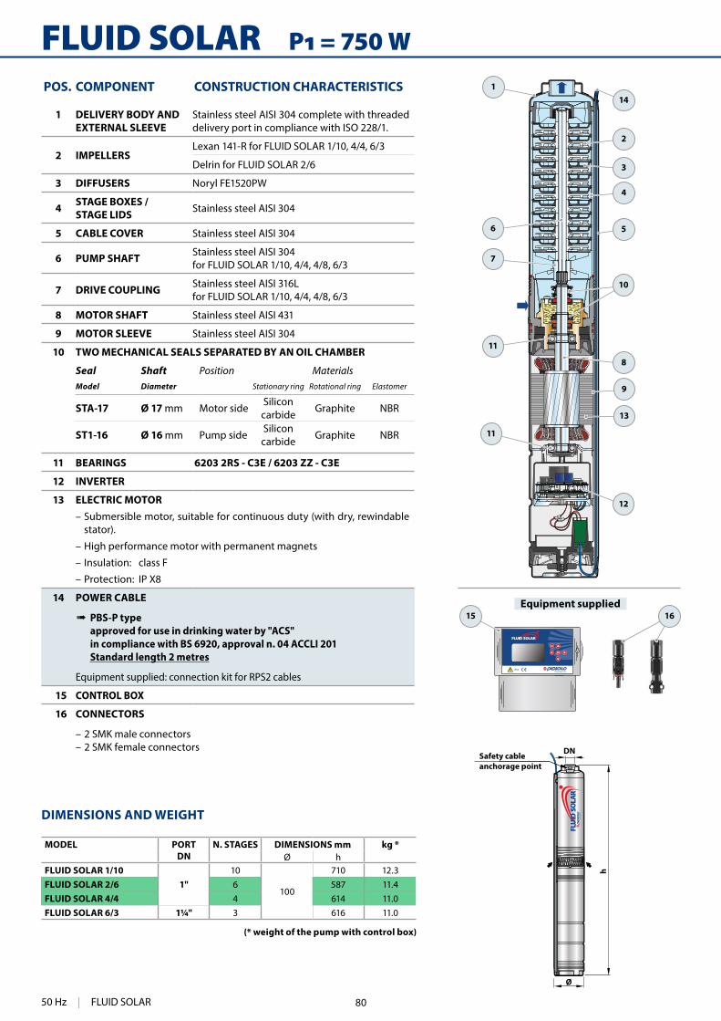
238
FLUID SOLAR1
2
3
4
6
7
11
11
12
8
13
9
10
5
14
1615h
Ø
DN
Equipment supplied
Safety cable anchorage point
POS. COMPONENT CONSTRUCTION CHARACTERISTICS
1 DELIVERY BODY ANDEXTERNAL SLEEVE
Stainless steel AISI 304 complete with threaded delivery port in compliance with ISO 228/1.
2 IMPELLERSLexan 141-R for FLUID SOLAR 1/10, 4/4, 6/3
Delrin for FLUID SOLAR 2/6
3 DIFFUSERS Noryl FE1520PW
4 STAGE BOXES / STAGE LIDS Stainless steel AISI 304
5 CABLE COVER Stainless steel AISI 304
6 PUMP SHAFT Stainless steel AISI 304 for FLUID SOLAR 1/10, 4/4, 4/8, 6/3
7 DRIVE COUPLING Stainless steel AISI 316Lfor FLUID SOLAR 1/10, 4/4, 4/8, 6/3
8 MOTOR SHAFT Stainless steel AISI 431
9 MOTOR SLEEVE Stainless steel AISI 304
10 TWO MECHANICAL SEALS SEPARATED BY AN OIL CHAMBER
Seal Shaft Position MaterialsModel Diameter Stationary ring Rotational ring Elastomer
STA-17 Ø 17 mm Motor side Siliconcarbide Graphite NBR
ST1-16 Ø 16 mm Pump side Siliconcarbide Graphite NBR
11 BEARINGS 6203 2RS - C3E / 6203 ZZ - C3E
12 INVERTER
13 ELECTRIC MOTOR – Submersible motor, suitable for continuous duty (with dry, rewindable stator).
– High performance motor with permanent magnets
– Insulation: class F
– Protection: IP X8
14 POWER CABLE
➠ PBS-P type approved for use in drinking water by "ACS" in compliance with BS 6920, approval n. 04 ACCLI 201 Standard length 2 metres
Equipment supplied: connection kit for RPS2 cables
15 CONTROL BOX
16 CONNECTORS
– 2 SMK male connectors – 2 SMK female connectors
DIMENSIONS AND WEIGHT
MODEL PORTDN
N. STAGES DIMENSIONS mm kg *Ø h
FLUID SOLAR 1/101"
10
100
710 12.3FLUID SOLAR 2/6 6 587 11.4FLUID SOLAR 4/4 4 614 11.0FLUID SOLAR 6/3 1¼" 3 616 11.0
(* weight of the pump with control box)
50 Hz | FLUID SOLAR 80

239
16
FLUID SOLAR1
2
3
4
6
7
11
11
12
8
13
9
10
5
14
15h
Ø
DN
Equipment supplied
Safety cable anchorage point
DIMENSIONS AND WEIGHT
POS. COMPONENT CONSTRUCTION CHARACTERISTICS
1 DELIVERY BODY ANDEXTERNAL SLEEVE
Stainless steel AISI 304, complete with threaded delivery port in compliance with ISO 228/1.
2 IMPELLERS Lexan 141-R
3 DIFFUSERS Noryl FE1520PW
4 STAGE BOXES / STAGE LIDS Stainless steel AISI 304
5 CABLE COVER Stainless steel AISI 304
6 PUMP SHAFT Stainless steel AISI 304
7 DRIVE COUPLING Stainless steel AISI 316L
8 MOTOR SHAFT Stainless steel AISI 431
9 MOTOR SLEEVE Stainless steel AISI 304
10 TWO MECHANICAL SEALS SEPARATED BY AN OIL CHAMBER
Seal Shaft Position MaterialsModel Diameter Stationary ring Rotational ring Elastomer
STA-17 Ø 17 mm Motor side Siliconcarbide Graphite NBR
ST1-16 Ø 16 mm Pump side Siliconcarbide Graphite NBR
11 BEARINGS 3203 B 2RS - C3E / 6203 ZZ - C3E
12 INVERTER
13 ELECTRIC MOTOR – Submersible motor, suitable for continuous duty (with dry, rewindable stator).
– High performance motor with permanent magnets
– Insulation: class F
– Protection: IP X8
14 POWER CABLE
➠ PBS-P type approved for use in drinking water by "ACS" in compliance with BS 6920, approval n. 04 ACCLI 201 Standard length 2 metres
Equipment supplied: connection kit for RPS2 cables
15 CONTROL BOX
16 CONNECTORS
N. 2 SMK male connectorsN. 2 SMK female connectorsN. 2 Y female/male-male connectors type MC4N. 2 Y male/female-female connectors type MC4
MODEL PORTDN
N. STAGES DIMENSIONS mm kg *Ø h
FLUID SOLAR 1/201"
20
100
990 13.9FLUID SOLAR 2/14 14 855 13.8FLUID SOLAR 4/8 8 772 13.7FLUID SOLAR 6/6 1¼" 6 776 13.7
(* weight of the pump with control box)
FLUID SOLAR | 50 Hz81
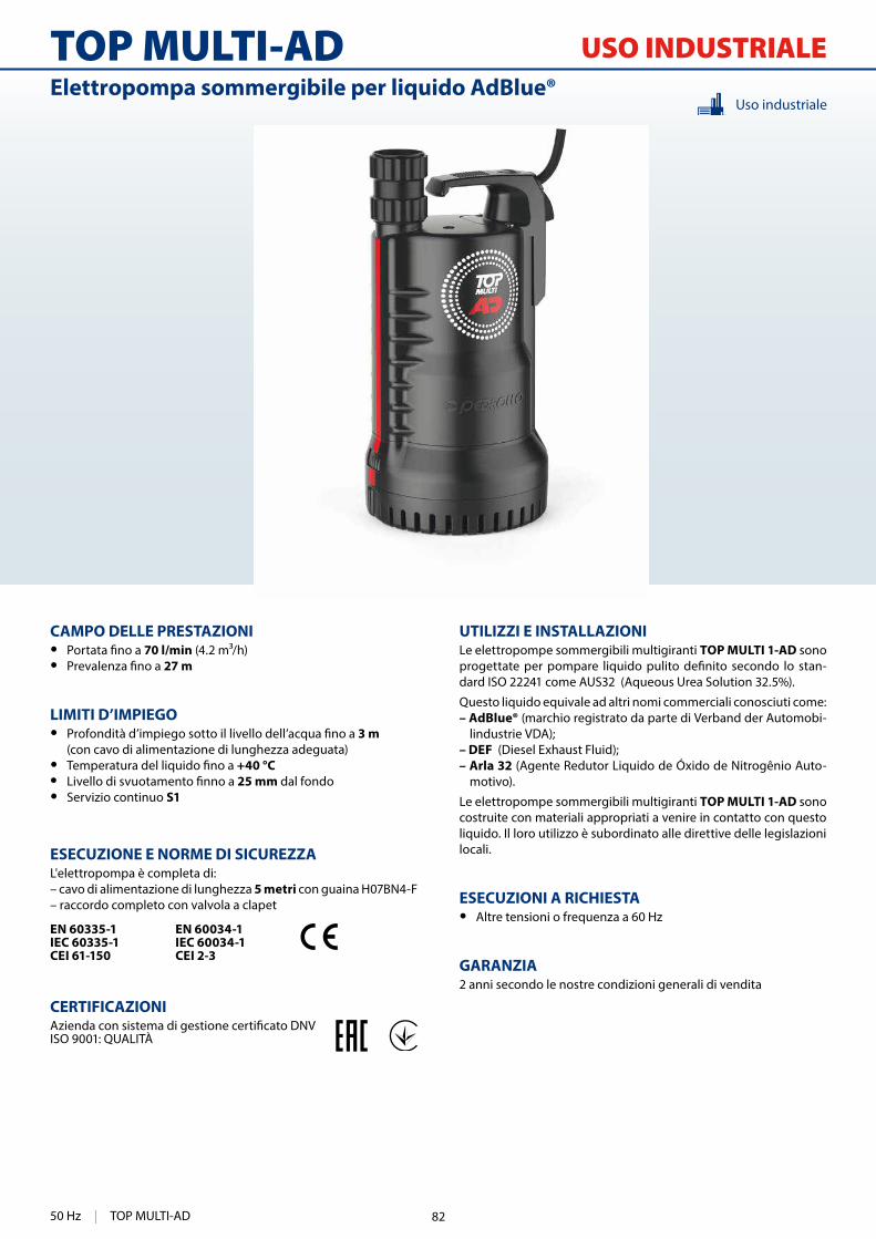
512
TOP MULTI-AD
UTILIZZI E INSTALLAZIONILe elettropompe sommergibili multigiranti TOP MULTI 1-AD sono
-dard ISO 22241 come AUS32 (Aqueous Urea Solution 32.5%).
Questo liquido equivale ad altri nomi commerciali conosciuti come:– AdBlue® (marchio registrato da parte di Verband der Automobi-
lindustrie VDA);– DEF (Diesel Exhaust Fluid);– Arla 32 (Agente Redutor Liquido de Óxido de Nitrogênio Auto-
motivo).
Le elettropompe sommergibili multigiranti TOP MULTI 1-AD sono costruite con materiali appropriati a venire in contatto con questo liquido. Il loro utilizzo è subordinato alle direttive delle legislazioni locali.
ESECUZIONI A RICHIESTA • Altre tensioni o frequenza a 60 Hz
GARANZIA 2 anni secondo le nostre condizioni generali di vendita
CAMPO DELLE PRESTAZIONI • 70 l/min (4.2 m³/h) • 27 m
LIMITI D’IMPIEGO • 3 m
(con cavo di alimentazione di lunghezza adeguata) • +40 °C • 25 mm dal fondo • Servizio continuo S1
ESECUZIONE E NORME DI SICUREZZAL'elettropompa è completa di:– cavo di alimentazione di lunghezza 5 metri con guaina H07BN4-F– raccordo completo con valvola a clapet
EN 60335-1IEC 60335-1CEI 61-150
EN 60034-1IEC 60034-1CEI 2-3
CERTIFICAZIONI
ISO 9001: QUALITÀ
Uso industrialeElettropompa sommergibile per liquido AdBlue®
USO INDUSTRIALE
50 Hz | TOP MULTI-AD 82
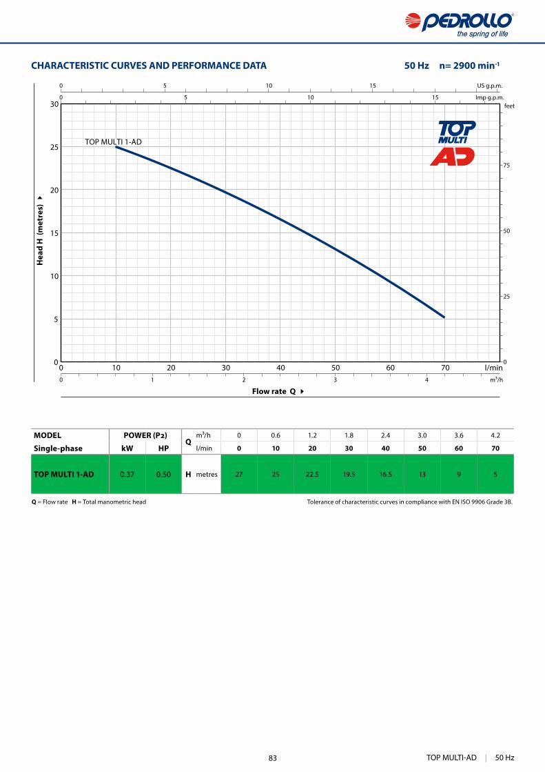
513
0 10 20 30 40 50 60 700
5
10
15
20
25
30
0
25
50
75
0 5 10 15
0 5 10 15
0 1 2 3 4
TOP MULTI 1-AD
US g.p.m.
Imp g.p.m.feet
l/minm³/h
CHARACTERISTIC CURVES AND PERFORMANCE DATA 50 Hz n= 2900 min
Flow rate Q
Hea
d H
(m
etre
s)
Q = Flow rate H = Total manometric head Tolerance of characteristic curves in compliance with EN ISO 9906 Grade 3B.
MODELQ
m³/h 0 0.6 1.2 1.8 2.4 3.0 3.6 4.2
Single-phase kW HP l/min 0 10 20 30 40 50 60 70
TOP MULTI 1-AD 0.37 0.50 H metres 27 25 22.5 19.5 16.5 13 9 5
TOP MULTI-AD | 50 Hz83

514
TOP MULTI-AD
9
1
16
15
2
4
5
6
8
13
12
12
14
11
10
3
7
12 BEARINGS 6201 ZZ - C3E / 6201 ZZ - C3E
13 CAPACITOR
Capacitance(230 V or 240 V) (110 V)
10 16
14 ELECTRIC MOTOR
TOP MULTI 1-AD: single-phase 230 V - 50 Hz with thermal overload protector incorporated into the winding.
– Insulation: class F– Protection: IP X8
15 HANDLE ASSEMBLY (resin sealed)
Complete with 5 metres long "H07BN4-F" power cable
16 PIPE COUPLINGThreaded 1¼" in compliance with ISO 228/1, complete with
(Included in the equipment)
POS. COMPONENT CONSTRUCTION CHARACTERISTICS
1 DELIVERY BODY
2 SUCTION FILTER
3 STAGE CASING
4 IMPELLER Noryl FE1520PW
5 DIFFUSER Noryl FE1520PW complete with anti-wear ring
6 VANE DIFFUSER
7 MOTOR CASING Stainless steel AISI 304
8 MOTOR CASING PLATE Stainless steel AISI 304
9 MOTOR SHAFT Stainless steel AISI 431
10 SHAFT WITH DOUBLE SEAL
Seal Shaft MaterialsModel Diameter Stationary ring Rotational ring Elastomer Metals
STA-12R SGE Ø 12 mm Silicon carbide Graphite EPDM AISI 304
11 LIP SEAL Ø 12 x Ø 19 x H 5 mm
50 Hz | TOP MULTI-AD 84

515TOP MULTI-AD | 50 Hz515
DN
a b
h
d
DIMENSIONS AND WEIGHT
p (m
inim
um)
(minimum)
Standard installation
ABSORPTION
MODEL VOLTAGE
Single-phase 230 V 240 V 110 V
TOP MULTI 1-AD 2.0 A 1.9 A 4.0 A
MODEL PORT N. STAGES
DIMENSIONS mm kg
Single-phase DN a b h d
TOP MULTI 1-AD 1¼" 2 180 170 295 25 220 5.8
PALLETIZATION
MODEL GROUPAGE CONTAINER
Single-phase n. pumps n. pumps
TOP MULTI 1-AD 60 100
TOP MULTI-AD | 50 Hz85

336
TOP-FLOORSubmersible DRAINAGE pumps
INSTALLATION AND USEThe TOP-FLOOR series is suitable for use with clear water that does not contain abrasive particles.Because of their ability to drain water to a level of 2 millimetres above ground level, they are suitable for use in domestic emergencies where a small area must be drained to the lowest possible level.
PATENTS - TRADE MARKS - MODELS • Registered EU Design n. 342159-0011
OPTIONS AVAILABLE ON REQUEST • • Pumps intended for use with aggressive liquids:
- TOP 1-FLOOR/LA- TOP 2-FLOOR/LA
• Special mechanical seal • Pumps with a 10 m long power cable.
➠ N.B.: Standard EN 60335-2-41 states that the power cable must be 10 m long for outdoor applications
• Other voltages or 60 Hz frequency
PERFORMANCE RANGE • Flow rate up to 160 l/min (9.6 m /h) • Head up to 9 m
APPLICATION LIMITS • 3 m maximum immersion depth
• Maximum liquid temperature +40 °C(Maximum liquid temperature +90 °C for a maximum of 3 minutes intermittent service)
• Passage of suspended solids up to Ø 2 mm • Suction down to 2 mm above ground level • Continuous service S1
CONSTRUCTION AND SAFETY STANDARDSThe pumps are complete with a 5 m power cable
EN 60335-1IEC 60335-1CEI 61-150
EN 60034-1IEC 60034-1CEI 2-3
CERTIFICATIONS
ISO 9001: QUALITY
Domestic use
Clear water
50 Hz | TOP-FLOOR 86

337
0 20 40 60 80 100 120 140 1600
1
2
3
4
5
6
7
8
90 10 20 30
0 10 20 30 40
0
5
10
15
20
25
0 1 2 3 4 5 6 7 8 9 10
TOP2-FLOOR
TOP1-FLOOR
US g.p.m.
Imp g.p.m.feet
l/minm³/h
Flow rate Q
Hea
d H
(m
etre
s)
CHARACTERISTIC CURVES AND PERFORMANCE DATA 50 Hz n= 2900 min
Q = Flow rate H = Total manometric head Tolerance of characteristic curves in compliance with EN ISO 9906 Grade 3B.
MODELQ
m³/h 0 1.2 2.4 3.6 4.8 6.0 7.2 8.4 9.6
Single-phase kW HP l/min 0 20 40 60 80 100 120 140 160
TOP 1-FLOOR 0.25 0.33
H metres
7 6 5 4 3 2 1
TOP 2-FLOOR 0.37 0.50 9 8 7 6 5 4 3 2 1
TOP-FLOOR | 50 Hz
= Stocked in Australia
Other models available upon request with 6 to 8 weeks lead time.
87

338
TOP-FLOOR
1
12
6
8
7
10
4 5 9
11
11
13
2
15
14
3
POS. COMPONENT CONSTRUCTION CHARACTERISTICS
1 PUMP BODY Technopolymer
2 SUCTION FILTER Technopolymer
3 SUCTION PLATE Stainless steel AISI 304 (AISI 316L for LA versions)
4 DIFFUSER Technopolymer
5 IMPELLER Noryl FE1520PW
6 MOTOR CASING Stainless steel AISI 304 (AISI 316L for LA versions)
7 MOTOR CASING PLATE Stainless steel AISI 304
8 MOTOR SHAFT Stainless steel AISI 431 (AISI 316L for LA versions)
9 SHAFT WITH DOUBLE SEAL AND OIL CHAMBER
Seal Shaft MaterialsModel Diameter Stationary ring Rotational ring Elastomer
STA-12R Ø 12 mm Ceramic Graphite NBR
10 LIP SEAL Ø 12 x Ø 19 x H 5 mm
11 BEARINGS 6201 ZZ / 6201 ZZ
12 CAPACITOR
Pump CapacitanceSingle-phase (230 V or 240 V) (110 V)
TOP 1-FLOOR 10 16 TOP 2-FLOOR 10 16
13 ELECTRIC MOTOR
TOP-FLOOR: single-phase 230 V - 50 Hz with thermal overload protector incorporated into the winding.
– Insulation: class F – Protection: IP X8
14 HANDLE ASSEMBLY (resin sealed)
Complete with 5 metres long “H07 RN-F” power cable with Schuko plug
15 HOSE CONNECTOR WITH RING NUT
Ø 25 mm hose connection for TOP1 - FLOORØ 35 mm hose connection for TOP2 - FLOOR
50 Hz | TOP-FLOOR 88
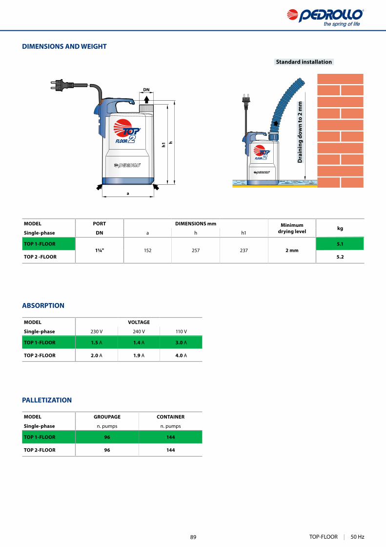
339
DN
a
h1
h
DIMENSIONS AND WEIGHT
Dra
inin
g do
wn
to 2
mm
Standard installation
ABSORPTION
MODEL VOLTAGE
Single-phase 230 V 240 V 110 V
TOP 1-FLOOR 1.5 A 1.4 A 3.0 A
TOP 2-FLOOR 2.0 A 1.9 A 4.0 A
MODEL PORT DIMENSIONS mm Minimumdrying level kg
Single-phase DN a h h1
TOP 1-FLOOR1¼" 152 257 237 2 mm
5.1
TOP 2 -FLOOR 5.2
MODEL GROUPAGE CONTAINER
Single-phase n. pumps n. pumps
TOP 1-FLOOR 96 144
TOP 2-FLOOR 96 144
PALLETIZATION
TOP-FLOOR | 50 Hz89

344
TEX® VORTEXSubmersible pumps
INSTALLATION AND USEThe TEX pump is suitable for use with dirty water that is not chem-ically aggressive towards the materials from which the pump is made.Because of the design solutions that have been adopted, such as the complete cooling of the motor and the shaft with double seal, these pumps are easy to use and reliable.They are suitable for use in applications such as clearing dirty wa-ter, emptying tanks, discharging domestic waste water, and for emptying collection traps containing suspended solids up to a maximum of Ø 30 mm.
PATENTS - TRADE MARKS - MODELS • Registered EU Design n. 005205556 • TEX® Registered Trade Mark n. 017884160
OPTIONS AVAILABLE ON REQUEST • Special mechanical seal • Pumps with a 10 m long power cable.
➠ N.B.: Standard EN 60335-2-41 states that the power cable must be 10 m long for outdoor applications
• • Other voltages or 60 Hz frequency
PERFORMANCE RANGE • Flow rate up to 240 l/min (14.4 m³/h) • Head up to 10 m
APPLICATION LIMITS • 5 m maximum immersion depth
• Maximum liquid temperature +40 °C(Maximum liquid temperature +90 °C for a maximum of 3 min-utes intermittent service)
• Passage of suspended solids up to Ø 30 mm • Suction down to 35 mm above ground level • Continuous service S1
CONSTRUCTION AND SAFETY STANDARDSThe pumps are complete with:
– 5 m long power cable
EN 60335-1IEC 60335-1CEI 61-150
EN 60034-1IEC 60034-1CEI 2-3
CERTIFICATIONS
ISO 9001: QUALITY
Domestic use
Sewage water
50 Hz | TEX® 90
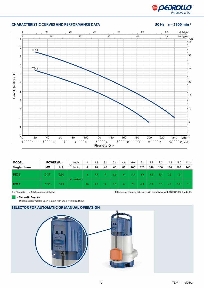
345
0 20 40 60 80 100 120 140 160 180 200 220 2400
1
2
3
4
5
6
7
8
9
10
11
0
5
10
15
20
25
30
35
0 10 20 30 40 50 60
0 10 20 30 40 50
0 1 2 3 4 5 6 7 8 9 10 11 12 13 14 15
US g.p.m.
Imp g.p.m.feet
l/minm³/h
TEX2
TEX3
Flow rate Q
Hea
d H
(met
res)
CHARACTERISTIC CURVES AND PERFORMANCE DATA 50 Hz n= 2900 min
SELECTOR FOR AUTOMATIC OR MANUAL OPERATION
Q = Flow rate H = Total manometric head Tolerance of characteristic curves in compliance with EN ISO 9906 Grade 3B.
MODELQ
m³/h 0 1.2 2.4 3.6 4.8 6.0 7.2 8.4 9.6 10.8 12.0 14.4
Single-phase kW HP l/min 0 20 40 60 80 100 120 140 160 180 200 240
TEX 2 0.37 0.50
H metres
8 7.5 7 6.5 6 5.5 4.8 4.2 3.4 2.5 1.5
TEX 3 0.55 0.75 10 9.5 9 8.5 8 7.5 6.8 6.2 5.5 4.8 3.9 2
TEX® | 50 Hz
= Stocked in Australia
Other models available upon request with 6 to 8 weeks lead time.
91
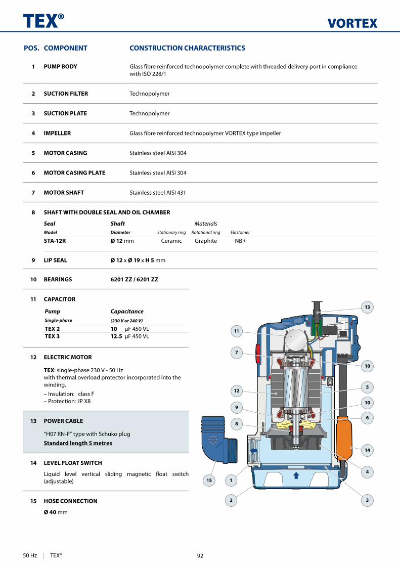
346
VORTEXTEX®
2
15
3
1
8
910
6
4
7
12
10
11
5
14
13
10 BEARINGS 6201 ZZ / 6201 ZZ
11 CAPACITOR
Pump CapacitanceSingle-phase (230 V or 240 V)
TEX 2 10 TEX 3 12.5
12 ELECTRIC MOTOR
TEX: single-phase 230 V - 50 Hz with thermal overload protector incorporated into the winding.
– Insulation: class F – Protection: IP X8
13 POWER CABLE
“H07 RN-F” type with Schuko plug
Standard length 5 metres
14 LEVEL FLOAT SWITCH
(adjustable)
15 HOSE CONNECTION
Ø 40 mm
POS. COMPONENT CONSTRUCTION CHARACTERISTICS
1 PUMP BODY with ISO 228/1
2 SUCTION FILTER Technopolymer
3 SUCTION PLATE Technopolymer
4 IMPELLER
5 MOTOR CASING Stainless steel AISI 304
6 MOTOR CASING PLATE Stainless steel AISI 304
7 MOTOR SHAFT Stainless steel AISI 431
8 SHAFT WITH DOUBLE SEAL AND OIL CHAMBER
Seal Shaft MaterialsModel Diameter Stationary ring Rotational ring Elastomer
STA-12R Ø 12 mm Ceramic Graphite NBR
9 LIP SEAL Ø 12 x Ø 19 x H 5 mm
50 Hz | TEX® 92

347
b
d
c
DN
a
hh1
e
f
g
Standard installation
DIMENSIONS AND WEIGHT
p (m
inim
um)
(minimum)
MODEL PORT Passageof solids
DIMENSIONS mm kg
Single-phase DN a b c d h1 h e f g p 1~
TEX 21¼" Ø 30 mm 205 88 117 118 69.5 318 35 110 or 130 220 350 220
6.1
TEX 3 6.8
MODEL VOLTAGE
Single-phase 230 V 240 V
TEX 2 2.3 A 2.2 A
TEX 3 3.3 A 3.2 A
ABSORPTION
PALLETIZATION
MODEL GROUPAGE
Single-phase n. pumps
TEX 2 60
TEX 3 60
TEX® | 50 Hz93
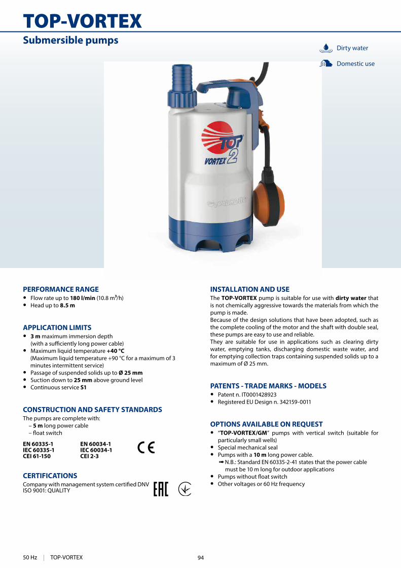
340
TOP-VORTEXSubmersible pumps
INSTALLATION AND USEThe TOP-VORTEX pump is suitable for use with dirty water that is not chemically aggressive towards the materials from which the pump is made.Because of the design solutions that have been adopted, such as the complete cooling of the motor and the shaft with double seal, these pumps are easy to use and reliable.They are suitable for use in applications such as clearing dirty water, emptying tanks, discharging domestic waste water, and for emptying collection traps containing suspended solids up to a maximum of Ø 25 mm.
PATENTS - TRADE MARKS - MODELS • Patent n. IT0001428923 • Registered EU Design n. 342159-0011
OPTIONS AVAILABLE ON REQUEST • “TOP-VORTEX/GM” pumps with vertical switch (suitable for
particularly small wells) • Special mechanical seal • Pumps with a 10 m long power cable.
➠ N.B.: Standard EN 60335-2-41 states that the power cable must be 10 m long for outdoor applications
• • Other voltages or 60 Hz frequency
PERFORMANCE RANGE • Flow rate up to 180 l/min (10.8 m /h) • Head up to 8.5 m
APPLICATION LIMITS • 3 m maximum immersion depth
• Maximum liquid temperature +40 °C(Maximum liquid temperature +90 °C for a maximum of 3 minutes intermittent service)
• Passage of suspended solids up to Ø 25 mm • Suction down to 25 mm above ground level • Continuous service S1
CONSTRUCTION AND SAFETY STANDARDSThe pumps are complete with:
– 5 m long power cable
EN 60335-1IEC 60335-1CEI 61-150
EN 60034-1IEC 60034-1CEI 2-3
CERTIFICATIONS
ISO 9001: QUALITY
Dirty water
Domestic use
50 Hz | TOP-VORTEX 94

341
0 20 40 60 80 100 120 140 160 1800
1
2
3
4
5
6
7
8
9
0
5
10
15
20
25
0 10 20 30 40
0 10 20 30 40
0 1 2 3 4 5 6 7 8 9 10 11
US g.p.m.
Imp g.p.m.feet
l/minm³/h
TOP2-VORTEX
TOP3-VORTEX
Flow rate Q
Hea
d H
(m
etre
s)
CHARACTERISTIC CURVES AND PERFORMANCE DATA 50 Hz n= 2900 min
Q = Flow rate H = Total manometric head Tolerance of characteristic curves in compliance with EN ISO 9906 Grade 3B.
MODELQ
m³/h 0 1.2 2.4 3.6 4.8 6.0 7.2 8.4 9.6 10.8
Single-phase kW HP l/min 0 20 40 60 80 100 120 140 160 180
TOP 2 - VORTEX 0.37 0.50
H metres
7 6.5 6 5.4 4.8 4.2 3.5 2.9 2.2 1.5
TOP 3 - VORTEX 0.55 0.75 8.5 8 7.4 6.8 6.1 5.5 4.7 4 3.2 2.5
TOP-VORTEX | 50 Hz
= Stocked in Australia
Other models available upon request with 6 to 8 weeks lead time.
95

342
TOP-VORTEX
12
6
8
7
10
4
5 9
11
11
13
2
15
1
14
3
11 BEARINGS 6201 ZZ / 6201 ZZ
12 CAPACITOR
Pump CapacitanceSingle-phase (230 V or 240 V) (110 V)
TOP 2 - VORTEX 10 16 TOP 3 - VORTEX 14 16
13 ELECTRIC MOTOR
TOP-VORTEX: single-phase 230 V - 50 Hz with thermal overload protector incorporated into the winding.
– Insulation: class F – Protection: IP X8
14 HANDLE ASSEMBLY (resin sealed)
Complete with: – 5 metres long “H07 RN-F” power cable with Schuko plug– Float switch
15 HOSE CONNECTOR WITH RING NUT
Hose connection Ø 35 mm
POS. COMPONENT CONSTRUCTION CHARACTERISTICS
1 PUMP BODY Technopolymer
2 SUCTION FILTER Technopolymer
3 SUCTION PLATE Technopolymer
4 DIFFUSER Technopolymer
5 IMPELLER Technopolymer VORTEX type
6 MOTOR CASING Stainless steel AISI 304
7 MOTOR CASING PLATE Stainless steel AISI 304
8 MOTOR SHAFT Stainless steel AISI 431
9 SHAFT WITH DOUBLE SEAL AND OIL CHAMBER
Seal Shaft MaterialsModel Diameter Stationary ring Rotational ring Elastomer
STA-12R Ø 12 mm Ceramic Graphite NBR
10 LIP SEAL Ø 12 x Ø 19 x H 5 mm
50 Hz | TOP-VORTEX 96

343
DN
a
hh1 ed
DN
a
b
h h1
ed g
DIMENSIONS AND WEIGHT
p (m
inim
um)
(minimum)
p (m
inim
um)
(minimum)
Standard installation
Standard installation
ABSORPTION
MODEL VOLTAGE
Single-phase 230 V 240 V 110 V
TOP 2 - VORTEX 2.0 A 1.9 A 4.0 A
TOP 3 - VORTEX 2.9 A 2.8 A 7.0 A
MODEL PORT DIMENSIONS mmkg
Single-phase DN a h h1 d e p
TOP 2 - VORTEX1¼" 152
288 26825 variable 350 350
5.3
TOP 3 - VORTEX 318 298 6.7
MODEL PORT DIMENSIONS mmkg
Single-phase DN a b h h1 d e g p
TOP 2 - VORTEX/GM1¼" 152 200
288 26825
170 40350 220
5.4
TOP 3 - VORTEX/GM 318 298 200 65 6.9
PALLETIZATION
MODEL GROUPAGE CONTAINER
Single-phase n. pumps n. pumps
TOP 2 - VORTEX 96 120
TOP 3 - VORTEX 96 120
TOP-VORTEX | 50 Hz97

350
RX
INSTALLATION AND USEThe RX series pumps are suitable for use with clear water that does not contain abrasive particles.Because of the design solutions that have been adopted, such as the complete cooling of the motor and the shaft with double seal, these pumps are easy to use and reliable.
event of an emergency, for the disposal of waste water in the home (from dishwashers, washing machines) and for emptying drainage traps.
PATENTS - TRADE MARKS - MODELS • Patent n. EP2313658 • Patent n. IT0001428923
OPTIONS AVAILABLE ON REQUEST • “RX-GM
particularly small wells) • Special mechanical seal • RX 1-2-3 pumps with a 10 m long power cable.
➠ N.B.: Standard EN 60335-2-41 states that the power cable must be 10 m long for outdoor applications
• • Other voltages or 60 Hz frequency
PERFORMANCE RANGE • Flow rate up to 300 l/min (18 m /h) • Head up to 20 m
APPLICATION LIMITS • 10 m maximum immersion depth
• Maximum liquid temperature +50 °C (Maximum liquid temperature +90 °C for a maximum of 3 minutes intermittent service)
• Passage of suspended solids up to Ø 10 mm • Suction level:
– 14 mm above ground level for RX 1-2-3– 25 mm above ground level for RX 4-5
• Continuous service S1
CONSTRUCTION AND SAFETY STANDARDSThe pumps are complete with: – 5 m long power cable for RX 1-2-3 – 10 m long power cable for RX 4-5
EN 60335-1IEC 60335-1CEI 61-150
EN 60034-1IEC 60034-1CEI 2-3
CERTIFICATIONS
ISO 9001: QUALITY
Submersible DRAINAGE pumps
Civil use
Domestic use
Clear water
50 Hz | RX 98
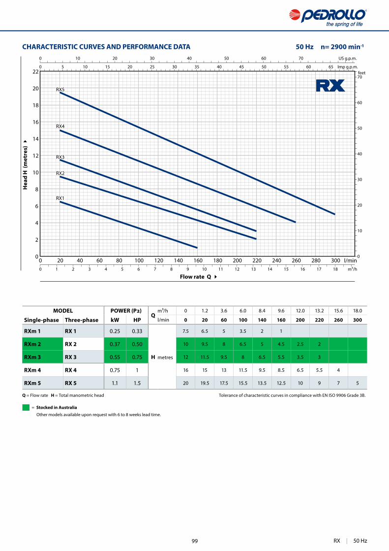
351
0 20 40 60 80 100 120 140 160 180 200 220 240 260 280 3000
2
4
6
8
10
12
14
16
18
20
22
0
10
20
30
40
50
60
70
0 10 20 30 40 50 60 70
0 5 10 15 20 25 30 35 40 45 50 55 60 65
0 1 2 3 4 5 6 7 8 9 10 11 12 13 14 15 16 17 18
RX1
RX2
RX3
RX5
RX4
US g.p.m.
Imp g.p.m.feet
l/minm³/h
Flow rate Q
Hea
d H
(m
etre
s)
CHARACTERISTIC CURVES AND PERFORMANCE DATA 50 Hz n= 2900 min
Q = Flow rate H = Total manometric head Tolerance of characteristic curves in compliance with EN ISO 9906 Grade 3B.
MODELQ
m³/h 0 1.2 3.6 6.0 8.4 9.6 12.0 13.2 15.6 18.0
Single-phase Three-phase kW HP l/min 0 20 60 100 140 160 200 220 260 300
RXm 1 RX 1 0.25 0.33
H metres
7.5 6.5 5 3.5 2 1
RXm 2 RX 2 0.37 0.50 10 9.5 8 6.5 5 4.5 2.5 2
RXm 3 RX 3 0.55 0.75 12 11.5 9.5 8 6.5 5.5 3.5 3
RXm 4 RX 4 0.75 1 16 15 13 11.5 9.5 8.5 6.5 5.5 4
RXm 5 RX 5 1.1 1.5 20 19.5 17.5 15.5 13.5 12.5 10 9 7 5
RX | 50 Hz
= Stocked in Australia
Other models available upon request with 6 to 8 weeks lead time.
99

352
RX 1-2-3
1
11
5
7
6
9
4 8
10
10
12
2
14
3
13
10 BEARINGS 6201 ZZ / 6201 ZZ
11 CAPACITOR
Pump CapacitanceSingle-phase (230 V or 240 V) (110 V)
RXm 1 10 16 RXm 2 10 16 RXm 3 14 16
12 ELECTRIC MOTOR
RXm: single-phase 230 V - 50 Hz with thermal overload protector incorporated into the winding
RX: three-phase 400 V - 50 Hz
– Insulation: class F – Protection: IP X8
13 POWER CABLE
"H07 RN-F" type(with Schuko plug for single-phase versions only)
Standard length 5 metres
14 FLOAT SWITCH(Only for single-phase versions)
POS. COMPONENT CONSTRUCTION CHARACTERISTICS
1 PUMP BODY Stainless steel AISI 304 with threaded port in compliance with ISO 228/1
2 SUCTION FILTER Stainless steel AISI 304
3 DIFFUSER Stainless steel AISI 304
4 IMPELLER Stainless steel AISI 304
5 MOTOR CASING Stainless steel AISI 304
6 MOTOR CASING PLATE Stainless steel AISI 304
7 MOTOR SHAFT Stainless steel AISI 431
8 SHAFT WITH DOUBLE SEAL AND OIL CHAMBER
Seal Shaft MaterialsModel Diameter Stationary ring Rotational ring Elastomer
STA-12R Ø 12 mm Ceramic Graphite NBR
9 LIP SEAL Ø 12 x Ø 19 x H 5 mm
50 Hz | RX 1-2-3 100

353
DN
a
b
h h1
ed
DN
a
h h1
d e g
b
DIMENSIONS AND WEIGHT
p (m
inim
um)
(minimum)
p (m
inim
um)
(minimum)
Standard installation
Standard installation
ABSORPTION
MODEL VOLTAGE
Single-phase 230 V 240 V 110 V
RXm 1 1.5 A 1.4 A 3.0 A
RXm 2 2.0 A 2.0 A 4.0 A
RXm 3 3.6 A 3.4 A 7.2 A
MODEL VOLTAGE
Three-phase 230 V 400 V 240 V 415 V
RX 1 1.6 A 0.9 A 1.6 A 0.9 A
RX 2 1.7 A 1.0 A 1.7 A 1.0 A
RX 3 2.8 A 1.6 A 2.6 A 1.5 A
MODEL PORT DIMENSIONS mm kg
Single-phase Three-phase DN a b h h1 d e p 1~ 3~
RXm 1 RX 1
1¼" 147 24269 246
14 variable 350 350
6.1 5.5
RXm 2 RX 2 6.1 5.6
RXm 3 RX 3 298 277 7.6 7.0
PALLETIZATIONGROUPAGE
n. pumpsCONTAINER
n. pumps
96 144
96 144
96 144
MODEL PORT DIMENSIONS mm kg
Single-phase DN a b h h1 d e g p 1~
RXm 1-GM
1¼" 147 150270 247
14145 40
350 240
6.2
RXm 2-GM 6.2
RXm 3-GM 300 277 175 45 7.5
PALLETIZATIONGROUPAGE
n. pumpsCONTAINER
n. pumps
80 120
80 120
80 120
RX 1-2-3 | 50 Hz101

354
RX 4-5
1
10
5
7
6
4
8
9
9
11
2 13
12
3
9 BEARINGS 6203 ZZ-C3E / 6203 ZZ-C3E
10 CAPACITOR
Pump CapacitanceSingle-phase (230 V or 240 V) (110 V)
RXm 4 20 30 RXm 5 25 30
11 ELECTRIC MOTOR
RXm: single-phase 230 V - 50 Hz with thermal overload protector incorporated into the winding
RX: three-phase 400 V - 50 Hz
– Insulation: class F– Protection: IP X8
12 POWER CABLE
“H07 RN-F” type (with Schuko plug for single-phase versions only)
Standard length 10 metres
13 FLOAT SWITCHOnly for single-phase versions
POS. COMPONENT CONSTRUCTION CHARACTERISTICS
1 PUMP BODY Stainless steel AISI 304 with threaded port in compliance with ISO 228/1
2 SUCTION FILTER Stainless steel AISI 304
3 DIFFUSER Stainless steel AISI 304
4 IMPELLER Stainless steel AISI 304
5 MOTOR CASING Stainless steel AISI 304
6 MOTOR CASING PLATE Stainless steel AISI 304
7 MOTOR SHAFT Stainless steel AISI 431
8 SHAFT WITH DOUBLE MECHANICAL SEAL SEPARATED BY AN OIL CHAMBER
Seal Shaft Position MaterialsModel Diameter Stationary ring Rotational ring Elastomer
MG1-14D SIC Ø 14 mmMotor side Silicon carbide Graphite NBRPump side Silicon carbide Silicon carbide NBR
50 Hz | RX 4-5 102
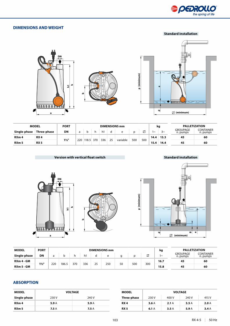
355
DN
a
hh1 e
d
DN
a
h
h1
d e g
bb
DIMENSIONS AND WEIGHT
p (m
inim
um)
(minimum)
p (m
inim
um)
(minimum)
Standard installation
Standard installation
ABSORPTION
MODEL VOLTAGE
Single-phase 230 V 240 V
RXm 4 5.9 A 5.9 A
RXm 5 7.5 A 7.5 A
MODEL VOLTAGE
Three-phase 230 V 400 V 240 V 415 V
RX 4 3.6 A 2.1 A 3.5 A 2.0 A
RX 5 6.1 A 3.5 A 5.9 A 3.4 A
MODEL PORT DIMENSIONS mm kg
Single-phase Three-phase DN a b h h1 d e p 1~ 3~
RXm 4 RX 41½" 220 118.5 370 336 25 variable 500 500
14.4 13.3
RXm 5 RX 5 15.4 14.4
MODEL PORT DIMENSIONS mm kg
Single-phase DN a b h h1 d e g p 1~
RXm 4 - GM1½" 220 186.5 370 336 25 250 50 500 300
16.7
RXm 5 - GM 15.8
PALLETIZATIONGROUPAGE
n. pumpsCONTAINER
n. pumps
45 60
45 60
PALLETIZATIONGROUPAGE
n. pumpsCONTAINER
n. pumps
45 60
45 60
RX 4-5 | 50 Hz103
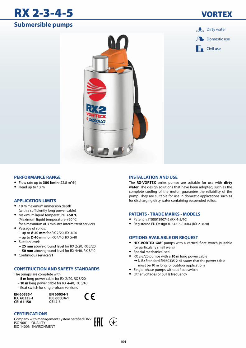
RX 2-3-4-5 VORTEXSubmersible pumps
INSTALLATION AND USEThe RX-VORTEX series pumps are suitable for use with dirty water. The design solutions that have been adopted, such as the complete cooling of the motor, guarantee the reliability of the pump. They are suitable for use in domestic applications such as for discharging dirty water containing suspended solids.
PATENTS - TRADE MARKS - MODELS • Patent n. IT0001390742 (RX 4-5/40) • Registered EU Design n. 342159-0014 (RX 2-3/20)
OPTIONS AVAILABLE ON REQUEST • “RX-VORTEX GM”
for particularly small wells) • Special mechanical seal • RX 2-3/20 pumps with a 10 m long power cable
➠ N.B.: Standard EN 60335-2-41 states that the power cable must be 10 m long for outdoor applications
• • Other voltages or 60 Hz frequency
PERFORMANCE RANGE • Flow rate up to 380 l/min (22.8 m /h) • Head up to 13 m
APPLICATION LIMITS • 10 m maximum immersion depth
• Maximum liquid temperature +50 °C (Maximum liquid temperature +90 °C for a maximum of 3 minutes intermittent service)
• Passage of solids:– up to Ø 20 mm for RX 2/20, RX 3/20– up to Ø 40 mm for RX 4/40, RX 5/40
• Suction level:– 25 mm above ground level for RX 2/20, RX 3/20– 50 mm above ground level for RX 4/40, RX 5/40
• Continuous service S1
CONSTRUCTION AND SAFETY STANDARDSThe pumps are complete with: – 5 m long power cable for RX 2/20, RX 3/20 – 10 m long power cable for RX 4/40, RX 5/40 oat switch for single-phase versions
EN 60335-1IEC 60335-1CEI 61-150
EN 60034-1IEC 60034-1CEI 2-3
CERTIFICATIONS
ISO 9001: QUALITYISO 14001: ENVIRONMENT
Civil use
Domestic use
Dirty water
104

297
0 20 40 60 80 100 120 140 160 180 200 220 240 260 280 300 320 340 360 3800
1
2
3
4
5
6
7
8
9
10
11
12
13
14
0
10
20
30
40
0 25 50 75
0 25 50 75
0 1 2 3 4 5 6 7 8 9 10 11 12 13 14 15 16 17 18 19 20 21 22 23
RX5/40
RX4/40
RX3/20
RX2/20
US g.p.m.
Imp g.p.m.feet
l/minm³/h
Flow rate Q
Hea
d H
(m
etre
s)
CHARACTERISTIC CURVES AND PERFORMANCE DATA 50 Hz n= 2900 rpm
MODEL POWER Q
m³/h 0 1.2 2.4 3.6 4.8 6 7.2 8.4 9.6 10.8 13.2 16.8 20.4 22.8
Single-phase Three-phase kW HP l/min 0 20 40 60 80 100 120 140 160 180 220 280 340 380
RXm 2/20 RX 2/20 0.37 0.50
H metres
7 6.5 6 5.5 4.8 4.3 3.7 3 2.5 2
RXm 3/20 RX 3/20 0.55 0.75 9 8 7.5 6.5 6 5.5 4.7 4.2 3.5 3
RXm 4/40 RX 4/40 0.75 1 10 9.5 8.7 8.5 7.7 7 6.5 6 5.5 4.7 3.7 2
RXm 5/40 RX 5/40 1.1 1.5 13 12.5 12 11.5 10.7 10 9.5 9 8.3 7.7 6.5 5 3 2
Q = Flow rate H = Total manometric head Tolerance of characteristic curves in compliance with EN ISO 9906 Grade 3B.
= Stocked in Australia
Other models available upon request with 6 to 8 weeks lead time.
105
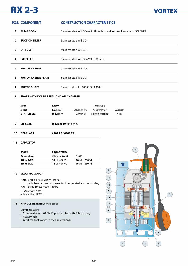
298
RX 2-3 VORTEX
1
11
10
5
7
6
9
4
8
10
12
2
13
3
10 BEARINGS 6201 ZZ / 6201 ZZ
11 CAPACITOR
Pump CapacitanceSingle-phase (230 V or 240 V) (110 V)
RXm 2/20 10 16RXm 3/20 14 16
12 ELECTRIC MOTOR
RXm: single-phase 230 V - 50 Hz with thermal overload protector incorporated into the winding
RX: three-phase 400 V - 50 Hz
– Insulation: class F– Protection: IP X8
13 HANDLE ASSEMBLY (resin sealed)
Complete with: – 5 metres long “H07 RN-F” power cable with Schuko plug– Float switch
POS. COMPONENT CONSTRUCTION CHARACTERISTICS
1 PUMP BODY Stainless steel AISI 304 with threaded port in compliance with ISO 228/1
2 SUCTION FILTER Stainless steel AISI 304
3 DIFFUSER Stainless steel AISI 304
4 IMPELLER Stainless steel AISI 304 VORTEX type
5 MOTOR CASING Stainless steel AISI 304
6 MOTOR CASING PLATE Stainless steel AISI 304
7 MOTOR SHAFT Stainless steel EN 10088-3 - 1.4104
8 SHAFT WITH DOUBLE SEAL AND OIL CHAMBER
Seal Shaft MaterialsModel Diameter Stationary ring Rotational ring Elastomer
STA-12R SIC Ø 12 mm Ceramic Silicon carbide NBR
9 LIP SEAL Ø 12 x Ø 19 x H 5 mm
106

299
DN
a
h
h1
ed
DN
a
h
h1
d e g
DIMENSIONS AND WEIGHT
p (m
inim
um)
(minimum)
ABSORPTION
MODEL VOLTAGE
Single-phase 230 V 240 V 110 V
RXm 2/20 2.6 A 2.5 A 5.2 A
RXm 3/20 3.2 A 3.1 A 6.4 A
MODEL PORT DIMENSIONS mm kg
Single-phase Three-phase DN a h h1 d e p 1~ 3~
RXm 2/20 RX 2/201¼” 147
290 27825 variable 350 350
6.1 6.1
RXm 3/20 RX 3/20 320 308 7.9 7.9
MODEL PORT DIMENSIONS mm kg
Single-phase DN a h h1 d e g p 1~
RXm 2/20-GM1¼” 147
305 27825
180 50350 240
6.2
RXm 3/20-GM 335 308 210 80 8.0
MODEL VOLTAGE
Three-phase 230 V 400 V 240 V 415 V
RX 2/20 1.9 A 1.1 A 1.8 A 1.05 A
RX 3/20 2.6 A 1.5 A 2.5 A 1.45 A
p (m
inim
um)
(minimum)
Standard installation
Standard installation
PALLETIZATIONGROUPAGE
n. pumpsCONTAINER
n. pumps
72 120
72 120
PALLETIZATIONGROUPAGE
n. pumpsCONTAINER
n. pumps
60 100
60 100
107

300
RX 4-5 VORTEX
1
10
5
7
6
4
8
9
9
11
2
12
3 13
9 BEARINGS 6203 ZZ-C3E / 6203 ZZ-C3E
10
CAPACITOR
Pump CapacitanceSingle-phase (230 V or 240 V) (110 V)
RXm 4/40 20 30RXm 5/40 25 30
11 ELECTRIC MOTOR
RXm: single-phase 230 V - 50 Hz with thermal overload protector incorporated into the winding
RX: three-phase 400 V - 50 Hz
– Insulation: class F– Protection: IP X8
12 POWER CABLE
“H07 RN-F” type (with Schuko plug for single-phase versions only)
Standard length 10 metres
13 FLOAT SWITCHOnly for single-phase versions
.
POS. COMPONENT CONSTRUCTION CHARACTERISTICS
1 PUMP BODY Stainless steel AISI 304 with threaded port in compliance with ISO 228/1
2 SUCTION FILTER Stainless steel AISI 304
3 DIFFUSER Stainless steel AISI 304
4 IMPELLER Stainless steel AISI 304 VORTEX type
5 MOTOR CASING Stainless steel AISI 304
6 MOTOR CASING PLATE Stainless steel AISI 304
7 MOTOR SHAFT Stainless steel EN 10088-3 - 1.4104
8 SHAFT WITH DOUBLE MECHANICAL SEAL SEPARATED BY AN OIL CHAMBER
Seal Shaft Position MaterialsModel Diameter Stationary ring Rotational ring Elastomer
MG1-14D SIC Ø 14 mmMotor side Silicon carbide Graphite NBRPump side Silicon carbide Silicon carbide NBR
108
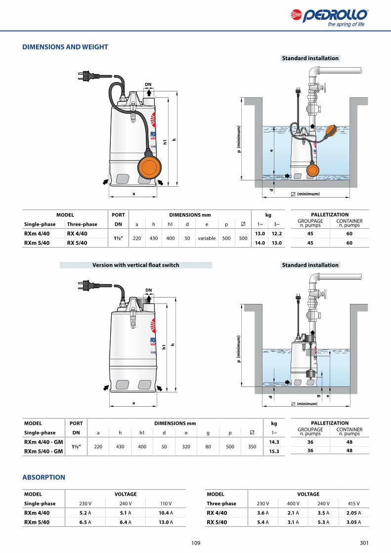
301
DN
a
h
h1
ed
DN
a
h
h1
d e g
DIMENSIONS AND WEIGHT
(minimum)
p (m
inim
um)
ABSORPTION
MODEL VOLTAGE
Single-phase 230 V 240 V 110 V
RXm 4/40 5.2 A 5.1 A 10.4 A
RXm 5/40 6.5 A 6.4 A 13.0 A
MODEL VOLTAGE
Three-phase 230 V 400 V 240 V 415 V
RX 4/40 3.6 A 2.1 A 3.5 A 2.05 A
RX 5/40 5.4 A 3.1 A 5.3 A 3.05 A
MODEL PORT DIMENSIONS mm kg
Single-phase Three-phase DN a h h1 d e p 1~ 3~
RXm 4/40 RX 4/401½” 220 430 400 50 variable 500 500
13.0 12.2
RXm 5/40 RX 5/40 14.0 13.0p
(min
imum
)
(minimum)
MODEL PORT DIMENSIONS mm kg
Single-phase DN a h h1 d e g p 1~
RXm 4/40 - GM1½” 220 430 400 50 320 80 500 350
14.3
RXm 5/40 - GM 15.3
Standard installation
Standard installation
PALLETIZATIONGROUPAGE
n. pumpsCONTAINER
n. pumps
45 60
45 60
PALLETIZATIONGROUPAGE
n. pumpsCONTAINER
n. pumps
36 48
36 48
109

418
ZX2 VORTEXSubmersible pumps
INSTALLATION AND USEZX2 series pumps are suitable for draining dirty water in domestic and civil applications and for pumping dirty water containing suspended solids up to Ø 40 mm. They distinguish themselves for the ease with which they are installed and their reliability under
.
PATENTS - TRADE MARKS - MODELS • Patent n° EP2313658 • Patent Pending n° BO2015A000116
OPTIONS AVAILABLE ON REQUEST • Pumps with a 10 m long power cable.
➠ N.B.: Standard EN 60335-2-41 states that the power cable must be 10 m long for outdoor applications
• • Other voltages or 60 Hz frequency
PERFORMANCE RANGE • Flow rate up to 400 l/min (24 m³/h) • Head up to 13 m
APPLICATION LIMITS • 5 m maximum immersion depth
• Maximum liquid temperature +40 °C • Passage of solids:
– up to Ø 30 mm for ZXm 2/30– up to Ø 40 mm for ZXm 2/40
• Minimum immersion depth for continuous service:– 265 mm for ZXm 2/30– 275 mm for ZXm 2/40
CONSTRUCTION AND SAFETY STANDARDSThe pumps are complete with:– 5 m long power cable
– kose connection Ø 50 mm
EN 60335-1IEC 60335-1CEI 61-150
EN 60034-1IEC 60034-1CEI 2-3
CERTIFICATIONS
ISO 9001: QUALITY
Civil use
Domestic use
Sewage water
50 Hz | ZX2 110

419
0 50 100 150 200 250 300 350 4000
1
2
3
4
5
6
7
8
9
10
11
12
13
14
0
5
10
15
20
25
30
35
40
0 25 50 75 100
0 25 50 75
0 5 10 15 20 25
US g.p.m.
Imp g.p.m.feet
l/minm³/h
ZXm 2/30
ZXm 2/40
CHARACTERISTIC CURVES AND PERFORMANCE DATA 50 Hz n= 2900 min
Flow rate Q
Hea
d H
(m
etre
s)
Q = Flow rate H = Total manometric head Tolerance of characteristic curves in compliance with EN ISO 9906 Grade 3B.
MODELQ
m³/h 0 1.5 3 6 9 12 15 18 19.2 21 24
Single-phase kW HP l/min 0 25 50 100 150 200 250 300 320 350 400
ZXm 2/30 0.55 0.75
H metres
13 12.5 11.8 10.6 9.3 7.6 5.8 3.3 2
ZXm 2/40 0.55 0.75 11.5 11 10.6 9.8 9.2 8.2 7.2 5.7 5.2 4 2
VORTEX IMPELLER
ZX2 | 50 Hz
= Stocked in Australia
Other models available upon request with 6 to 8 weeks lead time.
111
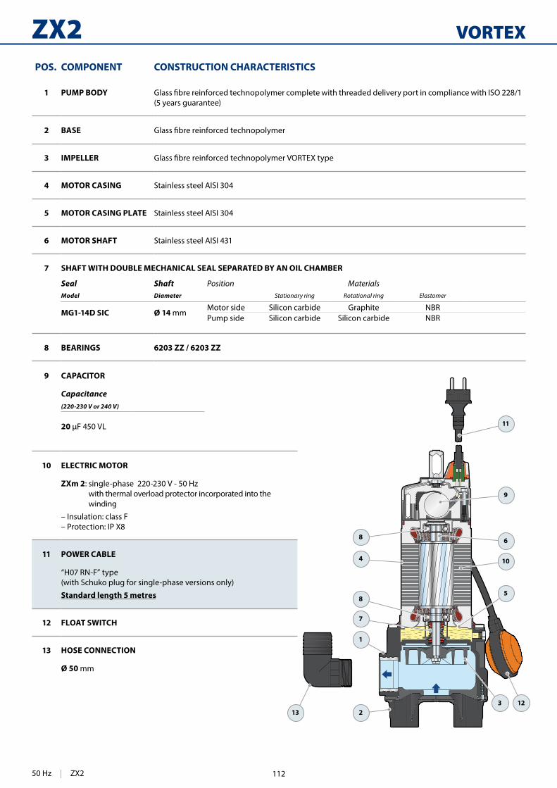
420
VORTEXZX2
11
9
6
10
5
2
1
7
8
8
4
12313
POS. COMPONENT CONSTRUCTION CHARACTERISTICS
1 PUMP BODY(5 years guarantee)
2 BASE
3 IMPELLER
4 MOTOR CASING Stainless steel AISI 304
5 MOTOR CASING PLATE Stainless steel AISI 304
6 MOTOR SHAFT Stainless steel AISI 431
7 SHAFT WITH DOUBLE MECHANICAL SEAL SEPARATED BY AN OIL CHAMBER
Seal Shaft Position MaterialsModel Diameter Stationary ring Rotational ring Elastomer
MG1-14D SIC Ø 14 mmMotor side Silicon carbide Graphite NBRPump side Silicon carbide Silicon carbide NBR
8 BEARINGS 6203 ZZ / 6203 ZZ
9 CAPACITOR
Capacitance(220-230 V or 240 V)
20
10 ELECTRIC MOTOR
ZXm 2: single-phase 220-230 V - 50 Hz with thermal overload protector incorporated into the winding
– Insulation: class F– Protection: IP X8
11 POWER CABLE
“H07 RN-F” type (with Schuko plug for single-phase versions only)
Standard length 5 metres
12 FLOAT SWITCH
13 HOSE CONNECTION
Ø 50 mm
50 Hz | ZX2 112

421
a
c
b
h
DN
h1
ed
DIMENSIONS AND WEIGHT
(minimum)p
(min
imum
)
Standard installation
MODEL PORT Passage of solids
DIMENSIONS mm kg
Single-phase DN a b c h h1 d e p 1~
ZXm 2/30
1½"
Ø 30 mm
90 81 118
412 73
50 variable 500 500
10.8
ZXm 2/40 Ø 40 mm 422 83 10.9
MODEL VOLTAGE
Single-phase 230 V 240 V
ZXm 2/30 4.0 A 3.9 A
ZXm 2/40 4.0 A 3.9 A
ABSORPTION PALLETIZATION
MODEL GROUPAGE CONTAINER
Single-phase n. pumps n. pumps
ZXm 2/30 54 72
ZXm 2/40 54 72
ZX2 | 50 Hz113

366
BC-STSubmersible pumps in stainless steel
Civil use
Domestic use
Industrial use
INSTALLATION AND USEBC-ST submersible pumps in stainless steel are recommended for draining dirty and sewage water in domestic, civil and industrial applications. They come equipped with a DOUBLE-CHANNEL impeller and are capable of pumping liquids containing short
sewage, waste water, surface water and water mixed with mud in
These pumps distinguish themselves for their reliability, which can
installations.
PATENTS - TRADE MARKS - MODELS • Patent n. EP2313658 • Patent n. IT0001428923
OPTIONS AVAILABLE ON REQUEST • • AISI 316L stainless steel pump shaft • Other voltages or 60 Hz frequency
PERFORMANCE RANGE • Flow rate up to 750 l/min (45 m /h) • Head up to 15 m
APPLICATION LIMITS • 5 m maximum immersion depth • Maximum liquid temperature +40 °C • Passage of suspended solids up to Ø 50 mm • Minimum immersion depth for continuous service: 300 mm
CONSTRUCTION AND SAFETY STANDARDS • 10 m long power cable • Float switch for single-phase versions
EN 60335-1IEC 60335-1CEI 61-150
EN 60034-1IEC 60034-1CEI 2-3
CERTIFICATIONS
ISO 9001: QUALITY
DOUBLE-CHANNEL
Sewage water
50 Hz | BC-ST 114
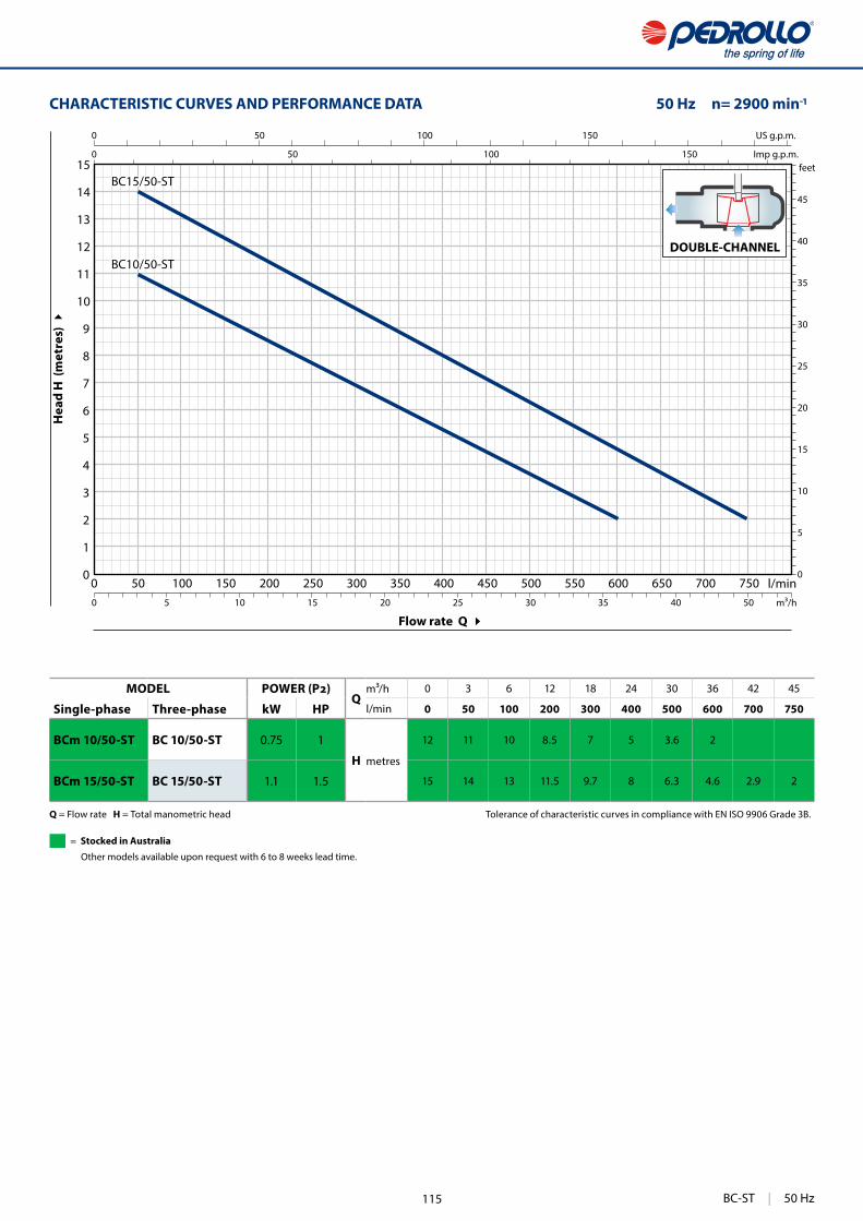
367
0 50 100 150 200 250 300 350 400 450 500 550 600 650 700 7500
1
2
3
4
5
6
7
8
9
10
11
12
13
14
15
0 1
0
5
10
15
20
25
30
35
40
45
0 50 100 150
0 50 100 150
0 5 10 15 20 25 30 35 40 50
US g.p.m.
Imp g.p.m.feet
l/minm³/h
BC15/50-ST
BC10/50-ST
CHARACTERISTIC CURVES AND PERFORMANCE DATA 50 Hz n= 2900 min
Flow rate Q
Hea
d H
(m
etre
s)
DOUBLE-CHANNEL
Q = Flow rate H = Total manometric head Tolerance of characteristic curves in compliance with EN ISO 9906 Grade 3B.
MODELQ
m³/h 0 3 6 12 18 24 30 36 42 45
Single-phase Three-phase kW HP l/min 0 50 100 200 300 400 500 600 700 750
BCm 10/50-ST BC 10/50-ST 0.75 1
H metres
12 11 10 8.5 7 5 3.6 2
BCm 15/50-ST BC 15/50-ST 1.1 1.5 15 14 13 11.5 9.7 8 6.3 4.6 2.9 2
BC-ST | 50 Hz
= Stocked in Australia
Other models available upon request with 6 to 8 weeks lead time.
115

368
BC-ST
1
4
10
7
8
8
9
6
2
3
11
512
POS. COMPONENT CONSTRUCTION CHARACTERISTICS
1 PUMP BODY Stainless steel AISI 304 with threaded port in compliance with ISO 228/1
2 BASE Stainless steel AISI 304
3 IMPELLER Precision cast stainless steel AISI 304 DOUBLE-CHANNEL type
4 MOTOR CASING Stainless steel AISI 304
5 MOTOR CASING PLATE Stainless steel AISI 304
6 MOTOR SHAFT Stainless steel AISI 431
7 SHAFT WITH DOUBLE MECHANICAL SEAL SEPARATED BY AN OIL CHAMBER
Seal Shaft Position MaterialsModel Diameter Stationary ring Rotational ring Elastomer
MG1-14D SIC Ø 14 mmMotor side Silicon carbide Graphite NBRPump side Silicon carbide Silicon carbide NBR
8 BEARINGS 6203 ZZ / 6203 ZZ
9 CAPACITOR
Pump CapacitanceSingle-phase (230 V or 240 V) (110 V)
BCm 10/50-ST 20 30
BCm 15/50-ST 25 –
10 ELECTRIC MOTOR
BCm: single-phase 230 V - 50 Hz with thermal overload protector incorporated into the winding
BC: three-phase 400 V - 50 Hz
– Insulation: class F– Protection: IP X8
11 POWER CABLE
“H07 RN-F” type (with Schuko plug for single-phase versions only)
Standard length 10 metres
12 FLOAT SWITCH(only for single-phase versions)
DOUBLE-CHANNEL
50 Hz | BC-ST 116

369
a
c
b
h
DN
h1
ed
DIMENSIONS AND WEIGHT
(minimum)p
(min
imum
)
Standard installation
MODEL PORT Passageof solids
DIMENSIONS mm kg
Single-phase Three-phase DN a b c h h1 d e p 1~ 3~
BCm 10/50-ST BC 10/50-ST2" Ø 50 mm 102 95 140
432102 60 variable 500 500
12.4 11.2
BCm 15/50-ST BC 15/50-ST 447 13.3 12.2
MODEL VOLTAGE
Single-phase 230 V 240 V 110 V
BCm 10/50-ST 5.0 A 4.8 A 10.0 A
BCm 15/50-ST 8.2 A 7.9 A –
MODEL VOLTAGE
Three-phase 230 V 400 V 240 V 415 V
BC 10/50-ST 3.6 A 2.1 A 3.5 A 2.0 A
BC 15/50-ST 5.5 A 3.2 A 5.4 A 3.1 A
ABSORPTION
PALLETIZATION
MODEL GROUPAGE CONTAINER
Single-phase Three-phase n. pumps n. pumps
BCm 10/50-ST BC 10/50-ST 54 72
BCm 15/50-ST BC 15/50-ST 54 72
BC-ST | 50 Hz117
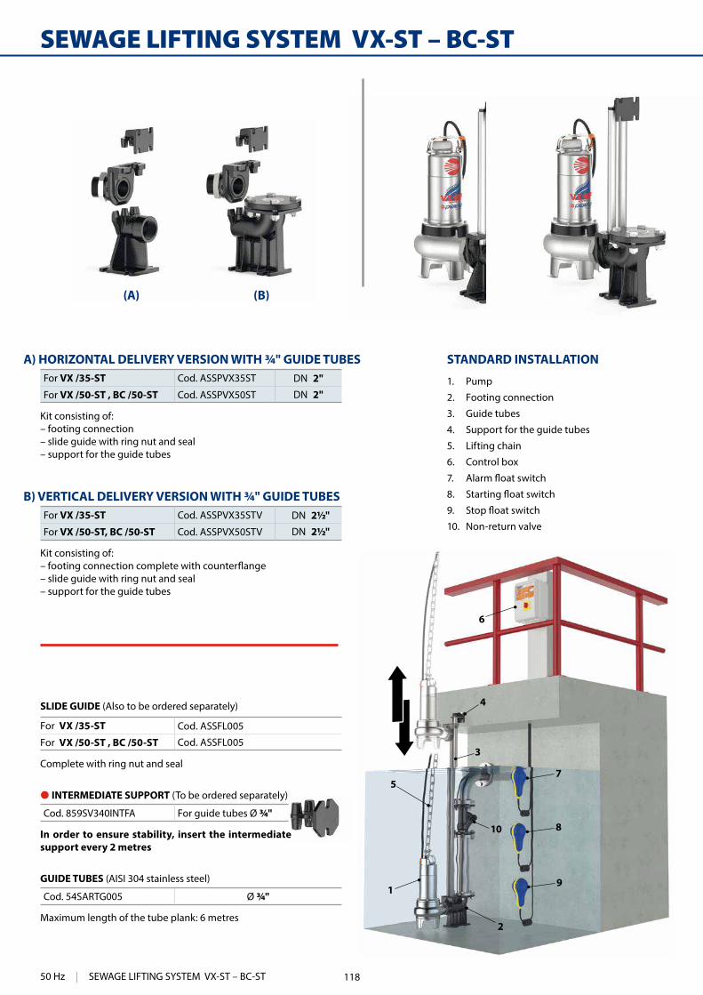
370
(A) (B)
7
8
9
2
10
4
3
5
1
6
SEWAGE LIFTING SYSTEM VX-ST – BC-ST
STANDARD INSTALLATION
1. Pump
2. Footing connection
3. Guide tubes
4. Support for the guide tubes
5. Lifting chain
6. Control box
7.
8.
9.
10. Non-return valve
A) HORIZONTAL DELIVERY VERSION WITH ¾" GUIDE TUBESFor VX /35-ST Cod. ASSPVX35ST DN 2"
For VX /50-ST , BC /50-ST Cod. ASSPVX50ST DN 2"
Kit consisting of: – footing connection– slide guide with ring nut and seal– support for the guide tubes
B) VERTICAL DELIVERY VERSION WITH ¾" GUIDE TUBESFor VX /35-ST Cod. ASSPVX35STV DN 2½"
For VX /50-ST, BC /50-ST Cod. ASSPVX50STV DN 2½"
Kit consisting of:
– slide guide with ring nut and seal– support for the guide tubes
SLIDE GUIDE (Also to be ordered separately)
For VX /35-ST Cod. ASSFL005
For VX /50-ST , BC /50-ST Cod. ASSFL005
Complete with ring nut and seal
GUIDE TUBES (AISI 304 stainless steel)
Cod. 54SARTG005 Ø ¾"
Maximum length of the tube plank: 6 metres
● INTERMEDIATE SUPPORT (To be ordered separately)
Cod. 859SV340INTFA For guide tubes Ø ¾"
In order to ensure stability, insert the intermediate support every 2 metres
50 Hz | SEWAGE LIFTING SYSTEM VX-ST – BC-ST 118

371
Ør
h
h2
h3
h1
a
p
i4i3
i1
i2
DN d e
Øm
b
chh1
i1Øm
i2
i3
DN
h3
Øg
c
p
i6
i5
Øn
i5
i4
Øn
Øg
h2
a b
MODEL Passageof solids
PORT DIMENSIONS mm
Single-phase Three-phase mm DN a b c p h h1 h2 h3 i1 i2 i3 i4 i5 i6 Øg Øm ØnVXm 8/35 -ST VX 8/35 -ST
40 2" 207
61 17
379406
43
130 165 85 94 16 40 50 48 ¾" 12 11
VXm 10/35 -ST VX 10/35 -STVXm 15/35 -ST VX 15/35 -ST 421VXm 8/50 -ST VX 8/50 -ST
50 2" 217 388
430
28VXm 10/50 -ST VX 10/50 -STVXm 15/50 -ST VX 15/50 -ST 445BCm 10/50 -ST BC 10/50 -ST 430BCm 15/50 -ST BC 15/50 -ST 445
MODEL Passageof solids
PORT DIMENSIONS mm
Single-phase Three-phase mm DN a b c d e p h h1 h2 h3 i1 i2 i3 i4 i5 Øg Øm Øn ØrVXm 8/35 -ST VX 8/35 -ST
40
2½"
207
61 52 125 165
495406
40
164 215 120 72 62 50 48 ¾" 14 11 18
VXm 10/35 -ST VX 10/35 -STVXm 15/35 -ST VX 15/35 -ST 421VXm 8/50 -ST VX 8/50 -ST
50 217 507
430
26VXm 10/50 -ST VX 10/50 -STVXm 15/50 -ST VX 15/50 -ST 445BCm 10/50 -ST BC 10/50 -ST 430BCm 15/50 -ST BC 15/50 -ST 445
DIMENSIONS (Horizontal delivery version)
DIMENSIONS (Vertical delivery version)
● INTERMEDIATE SUPPORT
0 INTERMEDIATE SUPPORT
SEWAGE LIFTING SYSTEM VX-ST – BC-ST | 50 Hz119

376
BC-MF
INSTALLATION AND USEBC-MF submersible pumps are recommended for draining dirty and sewage water in domestic, civil and industrial applications. They come equipped with a DOUBLE-CHANNEL impeller and are
solids up to Ø 50 mm. They are ideal for pumping sewage, waste water, surface water and water mixed with mud in locations such
These pumps distinguish themselves for their reliability, which can
installations.
PATENTS - TRADE MARKS - MODELS • Patent n. EP2313658 • Patent n. IT0001428923
OPTIONS AVAILABLE ON REQUEST • • Other voltages or 60 Hz frequency
PERFORMANCE RANGE • Flow rate up to 750 l/min (45 m /h) • Head up to 15 m
APPLICATION LIMITS • 5 m maximum immersion depth • Maximum liquid temperature +40 °C • Passage of suspended solids up to Ø 50 mm • Minimum immersion depth for continuous service: 300 mm
CONSTRUCTION AND SAFETY STANDARDS • 10 m long power cable • Float switch for single-phase versions
EN 60335-1IEC 60335-1CEI 61-150
EN 60034-1IEC 60034-1CEI 2-3
CERTIFICATIONS
ISO 9001: QUALITY
Civil use
Domestic use
Industrial use
Submersible pumps in stainless steelDOUBLE-CHANNEL
Sewage water
50 Hz | BC-MF 120

377
0 50 100 150 200 250 300 350 400 450 500 550 600 650 700 7500
1
2
3
4
5
6
7
8
9
10
11
12
13
14
15
0
5
10
15
20
25
30
35
40
45
50
0 50 100 150
0 50 100 150
0 5 10 15 20 25 30 35 40 50
US g.p.m.
Imp g.p.m.feet
l/minm³/h
BC15/50-MF
BC10/50-MF
Flow rate Q
Hea
d H
(m
etre
s)
CHARACTERISTIC CURVES AND PERFORMANCE DATA 50 Hz n= 2900 min
DOUBLE-CHANNEL
Q = Flow rate H = Total manometric head Tolerance of characteristic curves in compliance with EN ISO 9906 Grade 3B.
MODELQ
m³/h 0 3 6 12 18 24 30 36 42 45
Single-phase Three-phase kW HP l/min 0 50 100 200 300 400 500 600 700 750
BCm 10/50-MF BC 10/50-MF 0.75 1
H metres
12 11 10 8.5 7 5 3.5 2
BCm 15/50-MF BC 15/50-MF 1.1 1.5 15 14 13 11.5 9.7 8 6.3 4.5 3 2
BC-MF | 50 Hz
= Stocked in Australia
Other models available upon request with 6 to 8 weeks lead time.
121

378
BC-MF
1
4
10
7
8
8
9
6
2
3
12
11
5
POS. COMPONENT CONSTRUCTION CHARACTERISTICS
1 PUMP BODY Precision cast stainless steel AISI 316L with threaded port in compliance with ISO 228/1
2 BASE Stainless steel AISI 304
3 IMPELLER Precision cast stainless steel AISI 304 DOUBLE-CHANNEL type
4 MOTOR CASING Stainless steel AISI 304
5 MOTOR CASING PLATE Stainless steel AISI 304
6 MOTOR SHAFT Stainless steel AISI 316L
7 SHAFT WITH DOUBLE MECHANICAL SEAL SEPARATED BY AN OIL CHAMBER
Seal Shaft Position MaterialsModel Diameter Stationary ring Rotational ring Elastomer
MG1-14D SIC Ø 14 mmMotor side Silicon carbide Graphite NBRPump side Silicon carbide Silicon carbide NBR
8 BEARINGS 6203 ZZ / 6203 ZZ
9 CAPACITOR
Pump CapacitanceSingle-phase (230 V or 240 V) (110 V)
BCm 10/50-MF 20 30
BCm 15/50-MF 25 –
10 ELECTRIC MOTOR
BCm: single-phase 230 V - 50 Hz with thermal overload protector incorporated into the winding
BC: three-phase 400 V - 50 Hz
– Insulation: class F– Protection: IP X8
11 POWER CABLE
“H07 RN-F” type (with Schuko plug for single-phase versions only)
Standard length 10 metres
12 FLOAT SWITCH(only for single-phase versions)
DOUBLE-CHANNEL
50 Hz | BC-MF 122
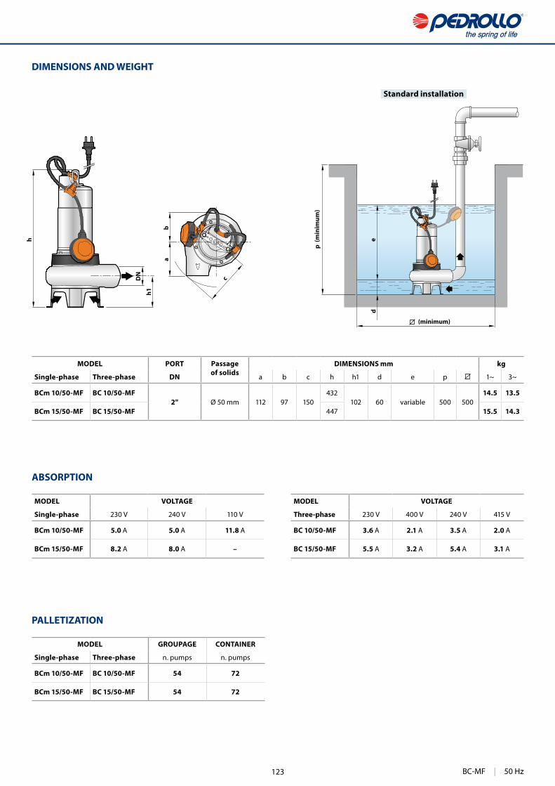
379
a
c
b
h
DN
h1
ed
DIMENSIONS AND WEIGHT
Standard installation
MODEL PORT Passageof solids
DIMENSIONS mm kg
Single-phase Three-phase DN a b c h h1 d e p 1~ 3~
BCm 10/50-MF BC 10/50-MF2" Ø 50 mm 112 97 150
432102 60 variable 500 500
14.5 13.5
BCm 15/50-MF BC 15/50-MF 447 15.5 14.3
MODEL VOLTAGE
Single-phase 230 V 240 V 110 V
BCm 10/50-MF 5.0 A 5.0 A 11.8 A
BCm 15/50-MF 8.2 A 8.0 A –
MODEL VOLTAGE
Three-phase 230 V 400 V 240 V 415 V
BC 10/50-MF 3.6 A 2.1 A 3.5 A 2.0 A
BC 15/50-MF 5.5 A 3.2 A 5.4 A 3.1 A
ABSORPTION
PALLETIZATION
MODEL GROUPAGE CONTAINER
Single-phase Three-phase n. pumps n. pumps
BCm 10/50-MF BC 10/50-MF 54 72
BCm 15/50-MF BC 15/50-MF 54 72
(minimum)p
(min
imum
)
BC-MF | 50 Hz123

380
7
8
9
2
10
4
3
5
1
6
(A) (B)
STANDARD INSTALLATION
1. Pump
2. Footing connection
3. Guide tubes
4. Support for the guide tubes
5. Lifting chain
6. Control box
7.
8.
9.
10. Non-return valve
SEWAGE LIFTING SYSTEM VX-MF – BC-MF
A) HORIZONTAL DELIVERY VERSION WITH ¾" GUIDE TUBESFor VX /35-MF Cod. ASSPVX35ST DN 2"
For VX /50-MF , BC /50-MF Cod. ASSPVX50ST DN 2"
Kit consisting of: – footing connection– slide guide with ring nut and seal– support for the guide tubes
B) VERTICAL DELIVERY VERSION WITH ¾" GUIDE TUBESFor VX /35-MF Cod. ASSPVX35STV DN 2½"
For VX /50-MF, BC /50-MF Cod. ASSPVX50STV DN 2½"
Kit consisting of:
– slide guide with ring nut and seal– support for the guide tubes
SLIDE GUIDE (Also to be ordered separately)
For VX /35-MF Cod. ASSFL005
For VX /50-MF , BC /50-MF Cod. ASSFL005
Complete with ring nut and seal
GUIDE TUBES (AISI 304 stainless steel)
Cod. 54SARTG005 Ø ¾"
Maximum length of the tube plank: 6 metres
● INTERMEDIATE SUPPORT (To be ordered separately)
Cod. 859SV340INTFA For guide tubes Ø ¾"
In order to ensure stability, insert the intermediate support every 2 metres
50 Hz | SEWAGE LIFTING SYSTEM VX-MF – BC-MF 124

381
Ør
h
h2
h3
h1
a
p
i4i3
i1
i2
DN d e
Øm
b
chh1
i1Øm
i2
i3
DN
h3
Øg
c
p
i6
i5
Øn
i5
i4
Øn
Øg
h2
a b
DIMENSIONS (Horizontal delivery version)
DIMENSIONS (Vertical delivery version)
MODEL Passageof solids
PORT DIMENSIONS mm
Single-phase Three-phase mm DN a b c p h h1 h2 h3 i1 i2 i3 i4 i5 i6 Øg Øm ØnVXm 8/35 -MF VX 8/35 -MF
40 2"
217 61 17
387406
45
165 130 85 94 16 40 50 48 ¾" 12 11
VXm 10/35 -MF VX 10/35 -MFVXm 15/35 -MF VX 15/35 -MF 421VXm 8/50 -MF VX 8/50 -MF
50 2"390
434
29VXm 10/50 -MF VX 10/50 -MFVXm 15/50 -MF VX 15/50 -MF 445BCm 10/50 -MF BC 10/50 -MF
50 2"430
BCm 15/50 -MF BC 15/50 -MF 445
MODEL Passageof solids
PORT DIMENSIONS mm
Single-phase Three-phase mm DN a b c d e p h h1 h2 h3 i1 i2 i3 i4 i5 Øg Øm Øn ØrVXm 8/35 -MF VX 8/35 -MF
40 2½"
217 61 52 125 165
504406
42
164 215 120 72 62 50 48 ¾" 14 11 18
VXm 10/35 -MF VX 10/35 -MFVXm 15/35 -MF VX 15/35 -MF 421VXm 8/50 -MF VX 8/50 -MF
50 2½" 507
430
26VXm 10/50 -MF VX 10/50 -MFVXm 15/50 -MF VX 15/50 -MF 445BCm 10/50 -MF BC 10/50 -MF 430BCm 15/50 -MF BC 15/50 -MF 445
� INTERMEDIATE SUPPORT
� INTERMEDIATE SUPPORT
SEWAGE LIFTING SYSTEM VX-MF – BC-MF | 50 Hz125

372
VX-MF VORTEX
INSTALLATION AND USEVX-MF submersible pumps in stainless steel are recommended for draining sewage water in domestic, civil and industrial applications, in every case where there are solid bodies in suspension, for example water mixed with mud, groundwater,
cellars, underground car parks, car washes, for emptying cesspools and for sewage disposal. These pumps distinguish themselves for their reliability, which can
installations.
PATENTS - TRADE MARKS - MODELS • Patent n. EP2313658 • Patent n. IT0001428923
OPTIONS AVAILABLE ON REQUEST • • Other voltages or 60 Hz frequency
PERFORMANCE RANGE • Flow rate up to 650 l/min (39 m³/h) • Head up to 14 m
APPLICATION LIMITS • 5 m maximum immersion depth • Maximum liquid temperature +40 °C • Passage of solids:
– up to Ø 40 mm for VX /35-MF– up to Ø 50 mm for VX /50-MF
• Minimum immersion depth for continuous service:– 280 mm for VX /35-MF– 300 mm for VX /50-MF
CONSTRUCTION AND SAFETY STANDARDS • 10 m long power cable • Float switch for single-phase versions
EN 60335-1IEC 60335-1CEI 61-150
EN 60034-1IEC 60034-1CEI 2-3
CERTIFICATIONS
ISO 9001: QUALITY
Civil use
Domestic use
Industrial use
Submersible pumps in stainless steelSewage water
50 Hz | VX-MF 126
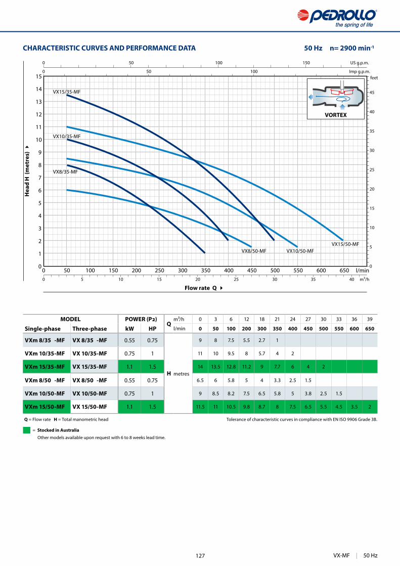
373
VORTEX
0 50 100 150 200 250 300 350 400 450 500 550 600 6500
1
2
3
4
5
6
7
8
9
10
11
12
13
14
15
0 1
0
5
10
15
20
25
30
35
40
45
0 50 100 150
0 50 100
0 5 10 15 20 25 30 35 40
US g.p.m.
Imp g.p.m.feet
l/minm³/h
VX8/35-MF
VX10/35-MF
VX15/35-MF
VX10/50-MFVX8/50-MFVX15/50-MF
VORTEX
CHARACTERISTIC CURVES AND PERFORMANCE DATA 50 Hz n= 2900 min
Flow rate Q
Hea
d H
(m
etre
s)
Q = Flow rate H = Total manometric head Tolerance of characteristic curves in compliance with EN ISO 9906 Grade 3B.
MODELQ
m³/h 0 3 6 12 18 21 24 27 30 33 36 39
Single-phase Three-phase kW HP l/min 0 50 100 200 300 350 400 450 500 550 600 650
VXm 8/35 -MF VX 8/35 -MF 0.55 0.75
H metres
9 8 7.5 5.5 2.7 1
VXm 10/35 -MF VX 10/35 -MF 0.75 1 11 10 9.5 8 5.7 4 2
VXm 15/35 -MF VX 15/35 -MF 1.1 1.5 14 13.5 12.8 11.2 9 7.7 6 4 2
VXm 8/50 -MF VX 8/50 -MF 0.55 0.75 6.5 6 5.8 5 4 3.3 2.5 1.5
VXm 10/50 -MF VX 10/50 -MF 0.75 1 9 8.5 8.2 7.5 6.5 5.8 5 3.8 2.5 1.5
VXm 15/50 -MF VX 15/50 -MF 1.1 1.5 11.5 11 10.5 9.8 8.7 8 7.5 6.5 5.5 4.5 3.5 2
VX-MF | 50 Hz
= Stocked in Australia
Other models available upon request with 6 to 8 weeks lead time.
127

374
VX-MF VORTEX
1
4
10
7
8
8
9
6
2
3
12
11
5
POS. COMPONENT CONSTRUCTION CHARACTERISTICS
1 PUMP BODY Precision cast stainless steel AISI 316L with threaded port in compliance with ISO 228/1
2 BASE Stainless steel AISI 304
3 IMPELLER Stainless steel AISI 304 VORTEX type
4 MOTOR CASING Stainless steel AISI 304
5 MOTOR CASING PLATE Stainless steel AISI 304
6 MOTOR SHAFT Stainless steel AISI 316L
7 SHAFT WITH DOUBLE MECHANICAL SEAL SEPARATED BY AN OIL CHAMBER
Seal Shaft Position MaterialsModel Diameter Stationary ring Rotational ring Elastomer
MG1-14D SIC Ø 14 mmMotor side Silicon carbide Graphite NBRPump side Silicon carbide Silicon carbide NBR
8 BEARINGS 6203 ZZ / 6203 ZZ
9 CAPACITOR
Pump CapacitanceSingle-phase (230 V or 240 V) (110 V)
VXm 8/35 -MFVXm 8/50 -MFVXm 10/35 -MFVXm 10/50 -MF
20 30
VXm 15/35 -MFVXm 15/50 -MF 25 –
10 ELECTRIC MOTOR
VXm: single-phase 230 V - 50 Hz with thermal overload protector incorporated into the winding
VX: three-phase 400 V - 50 Hz
– Insulation: class F– Protection: IP X8
11 POWER CABLE
“H07 RN-F” type (with Schuko plug for single-phase versions only)
Standard length 10 metres
12 FLOAT SWITCH(only for single-phase versions)
50 Hz | VX-MF 128
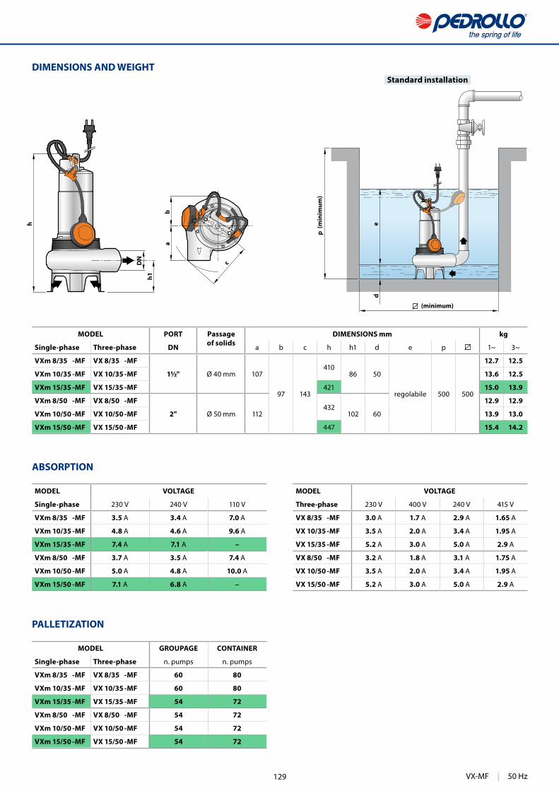
375
a
c
b
h
DN
h1
ed
DIMENSIONS AND WEIGHT
MODEL VOLTAGE
Single-phase 230 V 240 V 110 V
VXm 8/35 -MF 3.5 A 3.4 A 7.0 A
VXm 10/35 -MF 4.8 A 4.6 A 9.6 A
VXm 15/35 -MF 7.4 A 7.1 A –
VXm 8/50 -MF 3.7 A 3.5 A 7.4 A
VXm 10/50 -MF 5.0 A 4.8 A 10.0 A
VXm 15/50 -MF 7.1 A 6.8 A –
MODEL VOLTAGE
Three-phase 230 V 400 V 240 V 415 V
VX 8/35 -MF 3.0 A 1.7 A 2.9 A 1.65 A
VX 10/35 -MF 3.5 A 2.0 A 3.4 A 1.95 A
VX 15/35 -MF 5.2 A 3.0 A 5.0 A 2.9 A
VX 8/50 -MF 3.2 A 1.8 A 3.1 A 1.75 A
VX 10/50 -MF 3.5 A 2.0 A 3.4 A 1.95 A
VX 15/50 -MF 5.2 A 3.0 A 5.0 A 2.9 A
ABSORPTION
PALLETIZATION
MODEL GROUPAGE CONTAINER
Single-phase Three-phase n. pumps n. pumps
VXm 8/35 -MF VX 8/35 -MF 60 80
VXm 10/35 -MF VX 10/35 -MF 60 80
VXm 15/35 -MF VX 15/35 -MF 54 72
VXm 8/50 -MF VX 8/50 -MF 54 72
VXm 10/50 -MF VX 10/50 -MF 54 72
VXm 15/50 -MF VX 15/50 -MF 54 72
(minimum)
p (m
inim
um)
Standard installation
MODEL PORT Passageof solids
DIMENSIONS mm kg
Single-phase Three-phase DN a b c h h1 d e p 1~ 3~
VXm 8/35 -MF VX 8/35 -MF
1½" Ø 40 mm 107
97 143
41086 50
regolabile 500 500
12.7 12.5
VXm 10/35 -MF VX 10/35 -MF 13.6 12.5
VXm 15/35 -MF VX 15/35 -MF 421 15.0 13.9
VXm 8/50 -MF VX 8/50 -MF
2" Ø 50 mm 112432
102 60
12.9 12.9
VXm 10/50 -MF VX 10/50 -MF 13.9 13.0
VXm 15/50 -MF VX 15/50 -MF 447 15.4 14.2
VX-MF | 50 Hz129
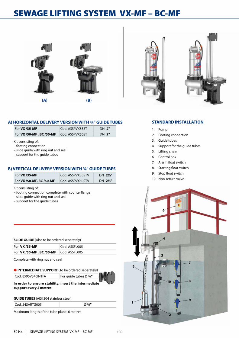
380
7
8
9
2
10
4
3
5
1
6
(A) (B)
STANDARD INSTALLATION
1. Pump
2. Footing connection
3. Guide tubes
4. Support for the guide tubes
5. Lifting chain
6. Control box
7.
8.
9.
10. Non-return valve
SEWAGE LIFTING SYSTEM VX-MF – BC-MF
A) HORIZONTAL DELIVERY VERSION WITH ¾" GUIDE TUBESFor VX /35-MF Cod. ASSPVX35ST DN 2"
For VX /50-MF , BC /50-MF Cod. ASSPVX50ST DN 2"
Kit consisting of: – footing connection– slide guide with ring nut and seal– support for the guide tubes
B) VERTICAL DELIVERY VERSION WITH ¾" GUIDE TUBESFor VX /35-MF Cod. ASSPVX35STV DN 2½"
For VX /50-MF, BC /50-MF Cod. ASSPVX50STV DN 2½"
Kit consisting of:
– slide guide with ring nut and seal– support for the guide tubes
SLIDE GUIDE (Also to be ordered separately)
For VX /35-MF Cod. ASSFL005
For VX /50-MF , BC /50-MF Cod. ASSFL005
Complete with ring nut and seal
GUIDE TUBES (AISI 304 stainless steel)
Cod. 54SARTG005 Ø ¾"
Maximum length of the tube plank: 6 metres
● INTERMEDIATE SUPPORT (To be ordered separately)
Cod. 859SV340INTFA For guide tubes Ø ¾"
In order to ensure stability, insert the intermediate support every 2 metres
50 Hz | SEWAGE LIFTING SYSTEM VX-MF – BC-MF 130

381
Ør
h
h2
h3
h1
a
p
i4i3
i1
i2
DN d e
Øm
b
chh1
i1Øm
i2
i3
DN
h3
Øg
c
p
i6
i5
Øn
i5
i4
Øn
Øg
h2
a b
DIMENSIONS (Horizontal delivery version)
DIMENSIONS (Vertical delivery version)
MODEL Passageof solids
PORT DIMENSIONS mm
Single-phase Three-phase mm DN a b c p h h1 h2 h3 i1 i2 i3 i4 i5 i6 Øg Øm ØnVXm 8/35 -MF VX 8/35 -MF
40 2"
217 61 17
387406
45
165 130 85 94 16 40 50 48 ¾" 12 11
VXm 10/35 -MF VX 10/35 -MFVXm 15/35 -MF VX 15/35 -MF 421VXm 8/50 -MF VX 8/50 -MF
50 2"390
434
29VXm 10/50 -MF VX 10/50 -MFVXm 15/50 -MF VX 15/50 -MF 445BCm 10/50 -MF BC 10/50 -MF
50 2"430
BCm 15/50 -MF BC 15/50 -MF 445
MODEL Passageof solids
PORT DIMENSIONS mm
Single-phase Three-phase mm DN a b c d e p h h1 h2 h3 i1 i2 i3 i4 i5 Øg Øm Øn ØrVXm 8/35 -MF VX 8/35 -MF
40 2½"
217 61 52 125 165
504406
42
164 215 120 72 62 50 48 ¾" 14 11 18
VXm 10/35 -MF VX 10/35 -MFVXm 15/35 -MF VX 15/35 -MF 421VXm 8/50 -MF VX 8/50 -MF
50 2½" 507
430
26VXm 10/50 -MF VX 10/50 -MFVXm 15/50 -MF VX 15/50 -MF 445BCm 10/50 -MF BC 10/50 -MF 430BCm 15/50 -MF BC 15/50 -MF 445
● INTERMEDIATE SUPPORT
� INTERMEDIATE SUPPORT
SEWAGE LIFTING SYSTEM VX-MF – BC-MF | 50 Hz131
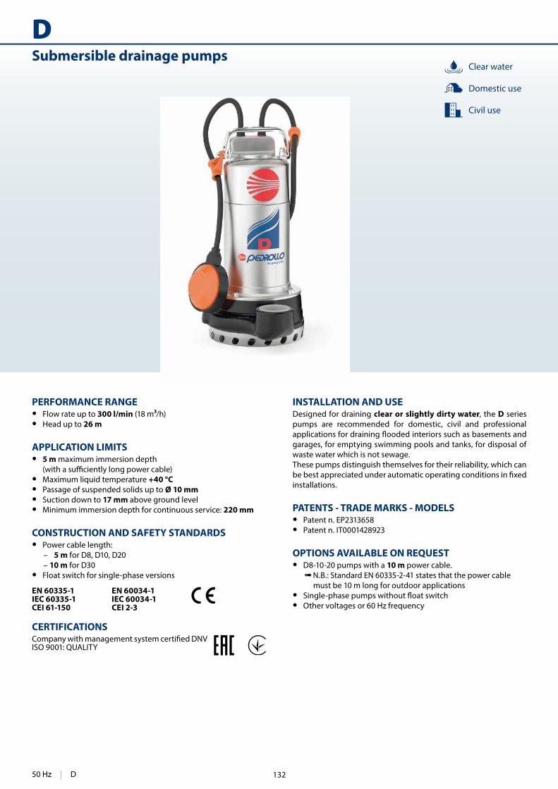
382
DSubmersible drainage pumps
INSTALLATION AND USEDesigned for draining clear or slightly dirty water, the D series pumps are recommended for domestic, civil and professional
garages, for emptying swimming pools and tanks, for disposal of waste water which is not sewage.These pumps distinguish themselves for their reliability, which can
installations.
PATENTS - TRADE MARKS - MODELS • Patent n. EP2313658 • Patent n. IT0001428923
OPTIONS AVAILABLE ON REQUEST • D8-10-20 pumps with a 10 m power cable.
➠ N.B.: Standard EN 60335-2-41 states that the power cable must be 10 m long for outdoor applications
• • Other voltages or 60 Hz frequency
PERFORMANCE RANGE • Flow rate up to 300 l/min (18 m /h) • Head up to 26 m
APPLICATION LIMITS • 5 m maximum immersion depth
• Maximum liquid temperature +40 °C • Passage of suspended solids up to Ø 10 mm • Suction down to 17 mm above ground level • Minimum immersion depth for continuous service: 220 mm
CONSTRUCTION AND SAFETY STANDARDS • Power cable length:
– 5 m for D8, D10, D20 – 10 m for D30
• Float switch for single-phase versions
EN 60335-1IEC 60335-1CEI 61-150
EN 60034-1IEC 60034-1CEI 2-3
CERTIFICATIONS
ISO 9001: QUALITY
Civil use
Domestic use
Clear water
50 Hz | D 132

383
0 25 50 75 100 125 150 175 200 225 250 275 3000
2
4
6
8
10
12
14
16
18
20
22
24
26
28
0 1
0
10
20
30
40
50
60
70
80
0 10 20 30 40 50 60 70 80
0 10 20 30 40 50 60
0 1 2 3 4 5 6 7 8 9 10 11 12 13 14 15 16 17 18
US g.p.m.
Imp g.p.m.feet
l/minm³/h
D30
D20
D10
D8
Flow rate Q
Hea
d H
(m
etre
s)
CHARACTERISTIC CURVES AND PERFORMANCE DATA 50 Hz n= 2900 min
Q = Flow rate H = Total manometric head Tolerance of characteristic curves in compliance with EN ISO 9906 Grade 3B.
MODELQ
m³/h 0 1.5 3.0 4.5 6.0 7.5 9.0 10.5 12.0 13.2 15.0 16.5 18.0
Single-phase Three-phase kW HP l/min 0 25 50 75 100 125 150 175 200 220 250 275 300
Dm 8 D 8 0.55 0.75
H metres
13 12.5 12 11 10 9 8 7 6 4.7 3
Dm 10 D 10 0.75 1 16 15.5 15 14 13.2 12.2 11.2 10 8.8 7.8 6 4.5 3
Dm 20 D 20 0.75 1 20 19 18.5 17.5 16.5 15.5 14.3 13 11.5 10 8
Dm 30 D 30 1.1 1.5 26 26 25 23.5 22 20.5 18.7 17 15 13.5 11 9
D | 50 Hz
= Stocked in Australia
Other models available upon request with 6 to 8 weeks lead time.
133
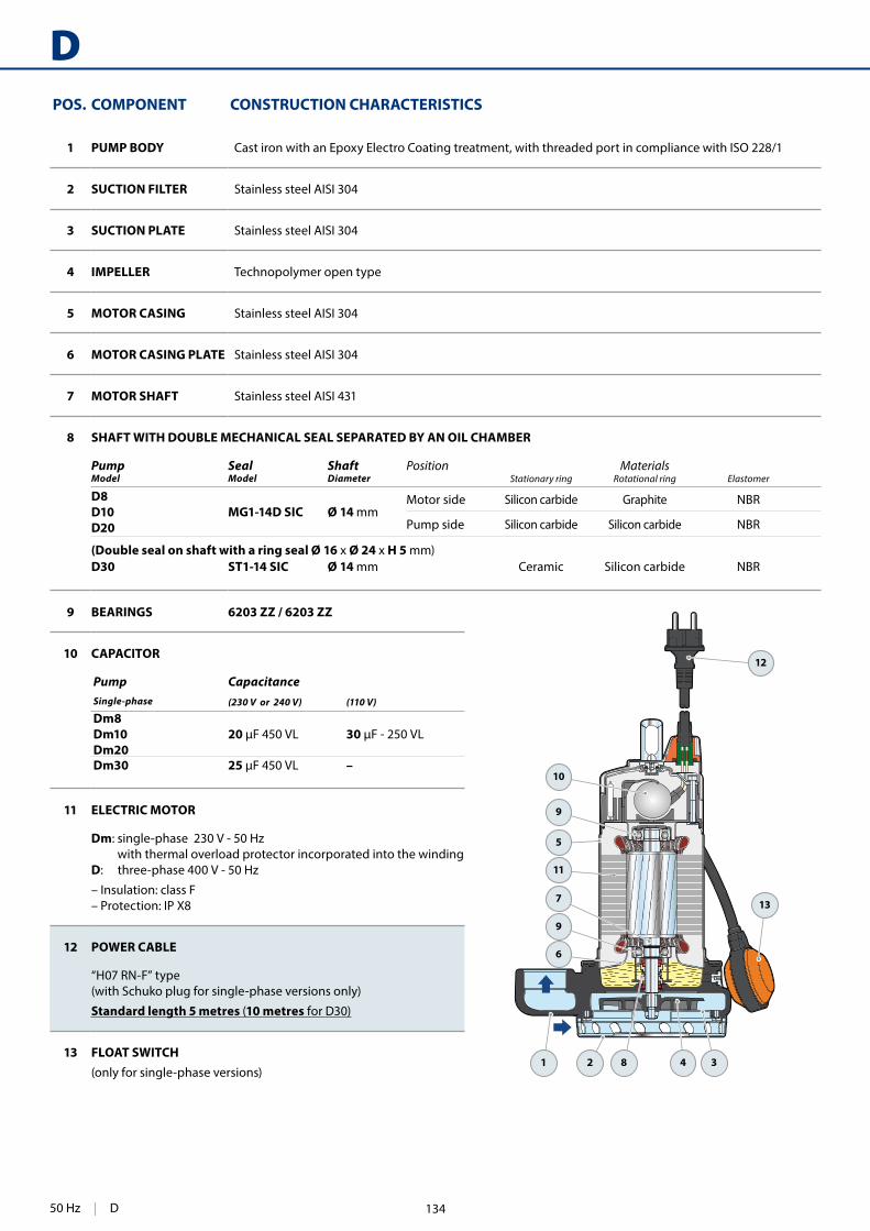
384
D
1
6
5
9
11
10
7
9
2 34
13
12
8
POS. COMPONENT CONSTRUCTION CHARACTERISTICS
1 PUMP BODY Cast iron with an Epoxy Electro Coating treatment, with threaded port in compliance with ISO 228/1
2 SUCTION FILTER Stainless steel AISI 304
3 SUCTION PLATE Stainless steel AISI 304
4 IMPELLER Technopolymer open type
5 MOTOR CASING Stainless steel AISI 304
6 MOTOR CASING PLATE Stainless steel AISI 304
7 MOTOR SHAFT Stainless steel AISI 431
8 SHAFT WITH DOUBLE MECHANICAL SEAL SEPARATED BY AN OIL CHAMBER
Pump Seal Shaft Position MaterialsModel Model Diameter Stationary ring Rotational ring Elastomer
D8 D10D20
MG1-14D SIC Ø 14 mmMotor side Silicon carbide Graphite NBR
Pump side Silicon carbide Silicon carbide NBR
(Double seal on shaft with a ring seal Ø 16 x Ø 24 x H 5 mm)D30 ST1-14 SIC Ø 14 mm Ceramic Silicon carbide NBR
9 BEARINGS 6203 ZZ / 6203 ZZ
10 CAPACITOR
Pump CapacitanceSingle-phase (230 V or 240 V) (110 V)
Dm8Dm10Dm20
20 30
Dm30 25 –
11 ELECTRIC MOTOR
Dm: single-phase 230 V - 50 Hz with thermal overload protector incorporated into the winding
D: three-phase 400 V - 50 Hz
– Insulation: class F– Protection: IP X8
12 POWER CABLE
“H07 RN-F” type(with Schuko plug for single-phase versions only)
Standard length 5 metres (10 metres for D30)
13 FLOAT SWITCH(only for single-phase versions)
50 Hz | D 134

385
a
b c
h
DN
h1
ed
DIMENSIONS AND WEIGHT
p (m
inim
um)
(minimum)
Standard installation
ABSORPTION
MODEL VOLTAGE
Single-phase 230 V 240 V 110 V
Dm 8 3.2 A 3.1 A 6.4 A
Dm 10 4.7 A 4.7 A 11.5 A
Dm 20 5.7 A 5.7 A 11.4 A
Dm 30 7.2 A 7.0 A –
MODEL VOLTAGE
Three-phase 230 V 400 V 240 V 415 V
D 8 2.8 A 1.6 A 2.6 A 1.5 A
D 10 3.5 A 2.0 A 3.3 A 1.9 A
D 20 4.2 A 2.4 A 4.0 A 2.3 A
D 30 5.2 A 3.0 A 5.0 A 2.9 A
MODEL PORT DIMENSIONS mm kg
Single-phase Three-phase DN a b c h h1 d e p 1~ 3~
Dm 8 D 8
1½" 11585
147344 73
17 variable 500 500
12.0 11.7
Dm 10 D 10 12.9 11.7
Dm 20 D 20 12.9 11.9
Dm 30 D 30 93 355 84 15.1 14.0
PALLETIZATION
MODEL GROUPAGE CONTAINER
Single-phase Three-phase n. pumps n. pumps
Dm 8 D 8 60 80
Dm 10 D 10 60 80
Dm 20 D 20 60 80
Dm 30 D 30 60 80
D | 50 Hz135

430
MCSubmersible pumps
INSTALLATION AND USEMC series pumps, made from heavy gauge robust cast iron, resist-
-NEL impeller and are capable of pumping liquids containing short
sewage, waste water, water mixed with mud, groundwater and surface water -ries, multi-storey and underground car parks, washing areas, etc.
PATENTS - TRADE MARKS - MODELS • Patent n. IT0001428923 • Registered EU Design n. 342159-0017
OPTIONS AVAILABLE ON REQUEST • QES control box for three-phase pumps • • Other voltages or 60 Hz frequency
GUARANTEE � For the following versions the incorporated thermal over-
load protector must be connected to the control box for the guarantee to be considered valid:
single-phase– MCm 30/50– MCm 30/70
three-phase– MC 15-20-30-40/50– MC 30-40/70
PERFORMANCE RANGE • Flow rate up to 1600 l/min • Head up to 25 m
APPLICATION LIMITS • 10 m maximum immersion depth
• Maximum liquid temperature +40 °C • Passage of solids:
– up to Ø 50 mm for MC /50– up to Ø 70 mm for MC /70
• Minimum immersion depth for continuous service:– 390 mm for MC /50– 430 mm for MC /70
CONSTRUCTION AND SAFETY STANDARDS • 10 m long power cable •
EN 60335-1IEC 60335-1CEI 61-150
EN 60034-1IEC 60034-1CEI 2-3
CERTIFICATIONS
ISO 9001: QUALITY
Civil use
Domestic use
Industrial use
DOUBLE-CHANNEL
Sewage water
50 Hz | MC 136

431
0 200 400 600 800 1000 1200 1400 16000
5
10
15
20
25
0
10
20
30
40
50
60
70
m³/h
US g.p.m.
Imp g.p.m.feet
l/min
MC30/50
MC40/50
MC20/50
MC15/50
MC40/70
MC30/70
Flow rate Q
Hea
d H
(m
etre
s)
CHARACTERISTIC CURVES AND PERFORMANCE DATA 50 Hz n= 2900 min
DOUBLE-CHANNEL
Q = Flow rate H = Total manometric head Tolerance of characteristic curves in compliance with EN ISO 9906 Grade 3B.
MODELQ
m³/h 0 6 12 18 24 30 36 42 48 54 60 66 72 90 96
Single-phase Three-phase kW HP l/min 0 100 200 300 400 500 600 700 800 900 1000 1100 1200 1500 1600
MCm 15/50 MC 15/50 1.1 1.5
H metres
16 14 12.5 10.5 8.5 6.5 4.5 3 1
MCm 20/50 MC 20/50 1.5 2 18 16 14 12.5 10.5 8.5 6.5 5 3 1
MCm 30/50 MC 30/50 2.2 3 24 22 20 18 16 14 12 10 8 6 4 2
– MC 40/50 3 4 25 24 22 20 18 16 14 12 10 8 6 4
MCm 30/70 MC 30/70 2.2 3 13 – 12 11 10.5 9.7 9 8 7.5 6.5 6 5 4.5 2
– MC 40/70 3 4 17 – 15 14 13.5 12.5 12 11 10.5 9.5 8.5 8 7 4.8 4
MC | 50 Hz
= Stocked in Australia
Other models available upon request with 6 to 8 weeks lead time.
137

432
MC
8
14
1
2
4
10
3
5
11
6
8
12
13
99
7
8 BEARINGS 6304 ZZ - C3 / 6304 ZZ - C3
9 CAPACITOR
Pump CapacitanceSingle-phase (230 V or 240 V)
MCm 15/50 31.5 MCm 20/50 50 MCm 30/50MCm 30/70 60
10 ELECTRIC MOTOR
MCm 15-20: single-phase 230 V - 50 Hz with thermal overload protector incorporated into the winding
➠ MCm 30: single-phase 230 V - 50 Hz with thermal overload protector incorporated into the winding to be connected to the control box
➠ MC: three-phase 400 V - 50 Hz. with thermal overload protector incorporated into the winding to be connected to the control box (supplied on demand)
– Insulation: class F– Protection: IP X8
11 POWER CABLE
10 metres long "H07 RN-F" cable
12 CONTROL BOX for MCm 15-20 (only for single-phase versions)
Complete with capacitor and manual reset motor protector
13 CONTROL BOX for MCm 30 (only for single-phase versions)
QES 300 MONO series
14 FLOAT SWITCH (only for single-phase versions)
POS. COMPONENT CONSTRUCTION CHARACTERISTICS
1 PUMP BODY Cast iron with threaded port in compliance with ISO 228/1
2 BASE Stainless steel AISI 304
3 IMPELLER Precision cast stainless steel AISI 304 DOUBLE-CHANNEL type
4 MOTOR CASING Cast iron
5 MOTOR CASING PLATE Cast iron
6 MOTOR SHAFT Stainless steel AISI 431
7 TWO MECHANICAL SEALS SEPARATED BY AN OIL CHAMBER
Seal Shaft Position MaterialsModel Diameter Stationary ring Rotational ring Elastomer
STA-20 Ø 20 mm Motor side Ceramic Graphite NBRSTA-19 Ø 19 mm Pump side Silicon carbide Silicon carbide NBR
Control box for MCm 15-20 (only for single-phase versions)
Control box for MCm 30 (only for single-phase versions)
Standard features Standard features
DOUBLE-CHANNEL
50 Hz | MC 138

433
a
b c
h
DN
h1
ed
DIMENSIONS AND WEIGHT
p (m
inim
um)
(minimum)
Standard installation
ABSORPTION
MODEL VOLTAGE
Single-phase 230 V 240 V
MCm 15/50 9.0 A 9.0 A
MCm 20/50 10.5 A 10.0 A
MCm 30/50 15.2 A 15.2 A
MCm 30/70 15.2 A 15.2 A
MODEL VOLTAGE
Three-phase 230–240 V 400–415 V 690–720 V
MC 15/50 6.1 A 3.5 A 2.0 A
MC 20/50 7.4 A 4.3 A 2.5 A
MC 30/50 9.9 A 5.7 A 3.3 A
MC 40/50 13.5 A 7.8 A 4.5 A
MC 30/70 10.2 A 5.9 A 3.4 A
MC 40/70 13.5 A 7.8 A 4.5 A
MODEL PORT Passageof solids
DIMENSIONS mm kg
Single-phase Three-phase DN a b c h h1 d e p 1~ 3~
MCm 15/50 MC 15/50
2½" Ø 50 mm 162 135 210
520
191 75
variable 800 800
37.8 36.2
MCm 20/50 MC 20/50 38.6 37.2
MCm 30/50 MC 30/50 517 43.0 39.0
– MC 40/50 530 – 43.4
MCm 30/70 MC 30/703" Ø 70 mm 180 150 237
577/563233 85
45.4 42.2
– MC 40/70 577 – 46.3
PALLETIZATION
MODEL GROUPAGE
Single-phase Three-phase n. pumps
MCm 15/50 MC 15/50 16
MCm 20/50 MC 20/50 16
MCm 30/50 MC 30/50 16
– MC 40/50 16
MCm 30/70 MC 30/70 12
– MC 40/70 12
MC | 50 Hz139

480
0 100 200 300 400 500 600 7000
5
10
15
20
25
30
35
40
45
0
25
50
75
100
125
0 50 100 150 200
0 50 100 150
0 5 10 15 20 25 30 35 40 45
US g.p.m.
Imp g.p.m.feet
l/minm³/h
SAR
PERFORMANCE RANGE 50 Hz n= 2900 min-1
CLEAR WASTE WATER - RAINWATER
Accumulation and lifting stations
Flow rate Q
Hea
d H
(m
etre
s)
Civil use
Agricultural use
Domestic use
SAR40 SAR100 SAR250SAR550
SAR550 (2 PUMPS)
50 Hz | SAR 140

481
0 100 200 300 400 500 600 700 800 900 1000 1100 1200 1300 1400 15000
5
10
15
20
25
30
0
25
50
75
0 100 200 300
0 100 200 300
0 10 20 30 40 50 60 70 80 90
US g.p.m.
Imp g.p.m.feet
l/minm³/h
PERFORMANCE RANGE 50 Hz n= 2900 min-1
DIRTY WASTE WATER
Flow rate Q
Hea
d H
(m
etre
s)
SAR40 SAR250SAR550
SAR100 SAR550 (2 PUMPS)
SAR | 50 Hz141

482
SAR 40CLEAR WASTE WATER - RAINWATER
DIRTY WASTE WATER
COMPONENTS • 40 litres polyethylene tank with cover plate • • Power cable: supplied with standard 5 metres cable with Schuko plug
(EN 60335-2-41 standard states that the power cable must be 10 metres long for outside use)
• Non-return valve • Accumulation stations with inlet tube 1 ½” gas, outlet 1 ¼” gas and vent ½” gas
MODEL POWER TANKCAPACITY
MAXIMUMFLOW RATE
MAXIMUMHEAD
kW HP litres litres/min metres
SAR 40 - TOP 2-VORTEX 0.37 0.50 40 180 6.5
SAR 40 - TEX 2 0.37 0.50 40 200 7.5
SAR 40 - TEX 3 0.55 0.75 40 240 9.5
SAR 40 - RXm2/20 0.37 0.50 40 180 6.5
MODEL POWER TANKCAPACITY
MAXIMUMFLOW RATE
MAXIMUMHEAD
kW HP litres litres/min metres
SAR 40 - TOP 1 0.25 0.33 40 160 6
SAR 40 - TOP 2 0.37 0.50 40 220 8
SAR 40 - TOP 3 0.55 0.75 40 260 10
SAR 40 - RXm 1 0.25 0.33 40 160 6.5
SAR 40 - RXm 2 0.37 0.50 40 220 9.5
SAR 40 - RXm 3 0.55 0.75 40 220 11.5
50 Hz | SAR 40 142
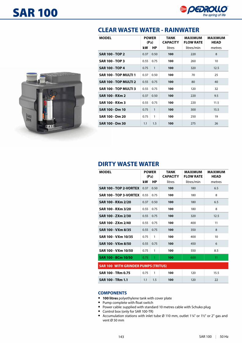
483
SAR 100CLEAR WASTE WATER - RAINWATER
DIRTY WASTE WATER
COMPONENTS • 100 litres polyethylene tank with cover plate • • Power cable: supplied with standard 10 metres cable with Schuko plug • Control box (only for SAR 100-TR) • Accumulation stations with inlet tube Ø 110 mm, outlet 1 ¼" or 1½" or 2" gas and
vent Ø 50 mm
MODEL POWER TANKCAPACITY
MAXIMUMFLOW RATE
MAXIMUMHEAD
kW HP litres litres/min metres
SAR 100 - TOP 2 0.37 0.50 100 220 8
SAR 100 - TOP 3 0.55 0.75 100 260 10
SAR 100 - TOP 4 0.75 1 100 320 12.5
SAR 100 - TOP MULTI 1 0.37 0.50 100 70 25
SAR 100 - TOP MULTI 2 0.55 0.75 100 80 40
SAR 100 - TOP MULTI 3 0.55 0.75 100 120 32
SAR 100 - RXm 2 0.37 0.50 100 220 9.5
SAR 100 - RXm 3 0.55 0.75 100 220 11.5
SAR 100 - Dm 10 0.75 1 100 300 15.5
SAR 100 - Dm 20 0.75 1 100 250 19
SAR 100 - Dm 30 1.1 1.5 100 275 26
MODEL POWER TANKCAPACITY
MAXIMUMFLOW RATE
MAXIMUMHEAD
kW HP litres litres/min metres
SAR 100 - TOP 2-VORTEX 0.37 0.50 100 180 6.5
SAR 100 - TOP 3-VORTEX 0.55 0.75 100 180 8
SAR 100 - RXm 2/20 0.37 0.50 100 180 6.5
SAR 100 - RXm 3/20 0.55 0.75 100 180 8
SAR 100 - ZXm 2/30 0.55 0.75 100 320 12.5
SAR 100 - ZXm 2/40 0.55 0.75 100 400 11
SAR 100 - VXm 8/35 0.55 0.75 100 350 8
SAR 100 - VXm 10/35 0.75 1 100 400 10
SAR 100 - VXm 8/50 0.55 0.75 100 450 6
SAR 100 - VXm 10/50 0.75 1 100 550 8.5
SAR 100 - BCm 10/50 0.75 1 100 600 11
SAR 100 WITH GRINDER PUMPS (TRITUS)
SAR 100 - TRm 0.75 0.75 1 100 120 15.5
SAR 100 - TRm 1.1 1.1 1.5 100 120 22
SAR 100 | 50 Hz143

484
SAR 250CLEAR WASTE WATER - RAINWATER
COMPONENTS • 250 litres polyethylene tank with cover plate • • Power cable: supplied with standard 10 metres cable with Schuko plug • Control box (only for SAR 250-TR) • Accumulation stations with inlet tube Ø 110 mm, outlet 1 ¼” or 1½” or 2” gas
and vent DN 50 or DN 75 • Coupling support and guide tubes for lowering of pump (only for VX-ST and
BC-ST)
DIRTY WASTE WATER
OPTIONS AVAILABLE ON REQUEST • Alarm KIT (Cod. KSKIT-ALLARME)
• 300 mm extension kit (Cod. KSKIT-308MA)Kit includes: extension kit for the installation of the polyethylene “SAR” tank at greater depths
• "SAR" stations with ball check valves and ball valve in the discharge pipe
MODEL POWER TANKCAPACITY
MAXIMUMFLOW RATE
MAXIMUMHEAD
kW HP litres litres/min metresSAR 250 - TOP 3 0.55 0.75 250 260 10
SAR 250 - TOP 4 0.75 1 250 320 12.5
SAR 250 - TOP 5 0.92 1.25 250 360 15
SAR 250 - RXm 3 0.55 0.75 250 220 11.5
SAR 250 - RXm 4 0.75 1 250 260 15
SAR 250 - RXm 5 1.1 1.5 250 300 19.5
SAR 250 - Dm 10 0.75 1 250 300 15.5
SAR 250 - Dm 20 0.75 1 250 250 19
SAR 250 - Dm 30 1.1 1.5 250 275 26
MODEL POWER TANKCAPACITY
MAXIMUMFLOW RATE
MAXIMUMHEAD
kW HP litres litres/min metresSAR 250 - TOP 2-VORTEX 0.37 0.50 250 180 6.5
SAR 250 - TOP 3-VORTEX 0.55 0.75 250 180 8
SAR 250 - RXm 3/20 0.55 0.75 250 180 8
SAR 250 - RXm 4/40 0.75 1 250 280 9.5
SAR 250 - RXm 5/40 1.1 1.5 250 380 12.5
SAR 250 - VXm10/35-ST 0.75 1 250 400 10.5
SAR 250 - VXm10/50-ST 0.75 1 250 550 9.5
SAR 250 - BCm 10/50-ST 0.75 1 250 600 11
SAR 250 - VXm 10/35 0.75 1 250 400 10
SAR 250 - VXm 15/35 1.1 1.5 250 500 13.5
SAR 250 - VXm 10/50 0.75 1 250 550 8.5
SAR 250 - VXm 15/50 1.1 1.5 250 650 11
SAR 250 - BCm 10/50 0.75 1 250 600 11
SAR 250 - BCm 15/50 1.1 1.5 250 750 14
SAR 250 WITH GRINDER PUMPS (TRITUS)SAR 250 - TRm 0.75 0.75 1 250 120 15.5
SAR 250 - TRm 1.1 1.1 1.5 250 120 22
SAR 250 - TRm 1.5 1.5 2 250 260 25
50 Hz | SAR 250 144
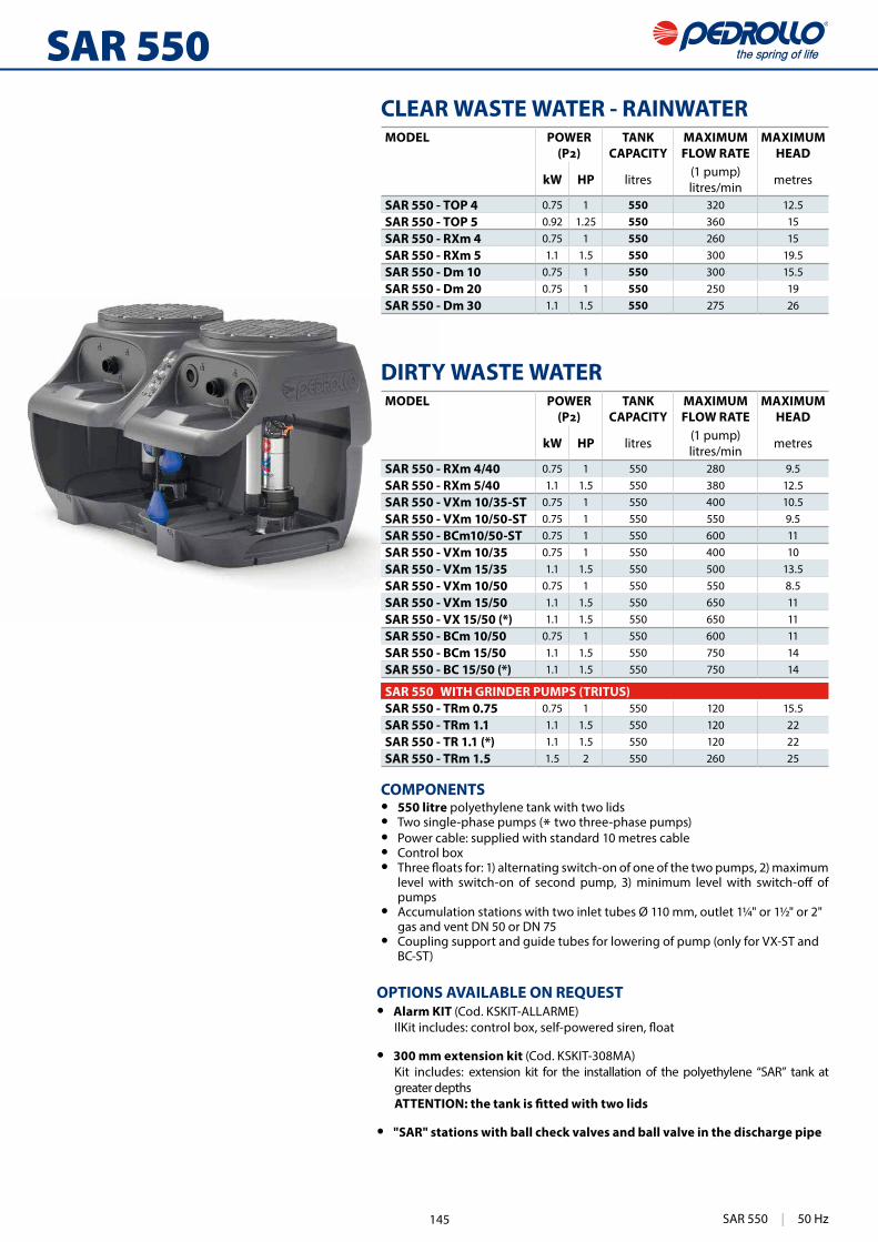
485
SAR 550CLEAR WASTE WATER - RAINWATER
DIRTY WASTE WATER
COMPONENTS• 550 litre polyethylene tank with two lids • Two single-phase pumps (* two three-phase pumps) • Power cable: supplied with standard 10 metres cable • Control box •
pumps • Accumulation stations with two inlet tubes Ø 110 mm, outlet 1¼" or 1½" or 2"
gas and vent DN 50 or DN 75 • Coupling support and guide tubes for lowering of pump (only for VX-ST and
BC-ST)
OPTIONS AVAILABLE ON REQUEST • Alarm KIT (Cod. KSKIT-ALLARME)
• 300 mm extension kit (Cod. KSKIT-308MA)Kit includes: extension kit for the installation of the polyethylene “SAR” tank at greater depths
• "SAR" stations with ball check valves and ball valve in the discharge pipe
MODEL POWER TANKCAPACITY
MAXIMUMFLOW RATE
MAXIMUMHEAD
kW HP litres (1 pump)litres/min metres
SAR 550 - TOP 4 0.75 1 550 320 12.5SAR 550 - TOP 5 0.92 1.25 550 360 15SAR 550 - RXm 4 0.75 1 550 260 15SAR 550 - RXm 5 1.1 1.5 550 300 19.5SAR 550 - Dm 10 0.75 1 550 300 15.5SAR 550 - Dm 20 0.75 1 550 250 19SAR 550 - Dm 30 1.1 1.5 550 275 26
MODEL POWER TANKCAPACITY
MAXIMUMFLOW RATE
MAXIMUMHEAD
kW HP litres (1 pump)litres/min metres
SAR 550 - RXm 4/40 0.75 1 550 280 9.5SAR 550 - RXm 5/40 1.1 1.5 550 380 12.5SAR 550 - VXm 10/35-ST 0.75 1 550 400 10.5SAR 550 - VXm 10/50-ST 0.75 1 550 550 9.5SAR 550 - BCm10/50-ST 0.75 1 550 600 11SAR 550 - VXm 10/35 0.75 1 550 400 10SAR 550 - VXm 15/35 1.1 1.5 550 500 13.5SAR 550 - VXm 10/50 0.75 1 550 550 8.5SAR 550 - VXm 15/50 1.1 1.5 550 650 11SAR 550 - VX 15/50 (*) 1.1 1.5 550 650 11SAR 550 - BCm 10/50 0.75 1 550 600 11SAR 550 - BCm 15/50 1.1 1.5 550 750 14SAR 550 - BC 15/50 (*) 1.1 1.5 550 750 14
SAR 550 WITH GRINDER PUMPS (TRITUS)SAR 550 - TRm 0.75 0.75 1 550 120 15.5SAR 550 - TRm 1.1 1.1 1.5 550 120 22SAR 550 - TR 1.1 (*) 1.1 1.5 550 120 22SAR 550 - TRm 1.5 1.5 2 550 260 25
SAR 550 | 50 Hz145

486
SAR
690 500
645
i1 i2
410
67.5
S
S
I
I
410
h
410 310
U
U
DIMENSIONS AND WEIGHT
MODEL PORTSh kg
I U S
SAR 40 - TOP 1
1½" 1¼" ½"
30514.0
SAR 40 - TOP 2 14.7
SAR 40 - TOP 3 335 16.1
SAR 40 - RXm 1305
14.2
SAR 40 - RXm 2 15.3
SAR 40 - RXm 3
335
16.9
SAR 40 - TOP 2-VORTEX 14.6
SAR 40 - TEX 2 15.8
SAR 40 - TEX 3 16.5
SAR 40 - RXm 2/20 15.6
MODEL PORTSi1 i2 kg
I U S
SAR 100 - TOP 2
DN 110
1¼"
DN 50 145 100
28.7
SAR 100 - TOP 3 30.1
SAR 100 - TOP 4 1½" 33.7
SAR 100 - TOP MULTI 1
1¼"
30.3
SAR 100 - TOP MULTI 2 32.9
SAR 100 - TOP MULTI 3 32.9
SAR 100 - RXm 2 29.3
SAR 100 - RXm 3 29.6
SAR 100 - Dm 10
1½"
36.6
SAR 100 - Dm 20 36.6
SAR 100 - Dm 30 38.6
SAR 100 - TOP 2-VORTEX
1¼"
28.7
SAR 100 - TOP 3-VORTEX 30.1
SAR 100 - RXm 2/20 29.6
SAR 100 - RXm 3/20 29.8
SAR 100 - ZXm 2/30
1½"
29.6
SAR 100 - ZXm 2/40 30.4
SAR 100 - VXm 8/35 36.4
SAR 100 - VXm 10/35 37.2
SAR 100 - VXm 8/50
2"
36.9
SAR 100 - VXm 10/50 37.7
SAR 100 - BCm 10/50 38.4
SAR 100 - TRm 0.751¼"
46.0
SAR 100 - TRm 1.1 47.6
50 Hz | SAR 146

487
IS
U 180
902
550
550
726
1476750902
180 170
170
884
640
640
656
68088
4
656
680
300
300
I
U
S
370
698
SU
I
370
698
SU
I
DIMENSIONS AND WEIGHT
Extension
Extension
Only for VX-ST, BC-ST versions
Only for VX-ST, BC-ST versions
MODEL PORTSkg
I U S
SAR 250 - TOP 3
DN 110
1¼"
DN 50
42.6SAR 250 - TOP 4
1½"46.2
SAR 250 - TOP 5 46.2SAR 250 - RXm 3 1¼" 47.0SAR 250 - RXm 4
1½"
50.0SAR 250 - RXm 5 51.0SAR 250 - Dm 10 51.2SAR 250 - Dm 20 53.5SAR 250 - Dm 30 51.2SAR 250 - TOP 2-VORTEX
1¼"44.0
SAR 250 - TOP 3-VORTEX 46.0SAR 250 - RXm 3/20 45.0SAR 250 - RXm 4/40
1½"53.0
SAR 250 - RXm 5/40 53.0SAR 250 - VXm10/35-ST
2"60.0
SAR 250 - VXm10/50-ST 60.0SAR 250 - BCm10/50-ST 60.5SAR 250 - VXm 10/35
1½"53.0
SAR 250 - VXm 15/35 54.0SAR 250 - VXm 10/50
2"
53.0SAR 250 - VXm 15/50 53.0SAR 250 - BCm 10/50 53.5SAR 250 - BCm 15/50 DN 75 55.0SAR 250 - TRm 0.75
1¼"DN 50
62.0SAR 250 - TRm 1.1 64.0SAR 250 - TRm 1.5 1½" 79.0
Male threaded �tting (female for VX-ST and BC-ST)
MODEL PORTSkg
I U S
SAR 550 - TOP 4
DN 110
1½" DN 50
96.0SAR 550 - TOP 5 95.2SAR 550 - RXm 4 103.0SAR 550 - RXm 5 105.0SAR 550 - Dm 10 101.2SAR 550 - Dm 20 101.2SAR 550 - Dm 30 105.7SAR 550 - RXm 4/40 105.0SAR 550 - RXm 5/40 106.0SAR 550 - VXm 10/35-ST
2"
DN 75
120.0SAR 550 - VXm 10/50-ST 121.0SAR 550 - BCm10/50-ST 122.0SAR 550 - VXm 10/35
1½"105.0
SAR 550 - VXm 15/35 106.0SAR 550 - VXm 10/50
2"
105.1SAR 550 - VXm 15/50 108.0SAR 550 - VX 15/50 107.0SAR 550 - BCm 10/50 109.0SAR 550 - BCm 15/50 108.0SAR 550 - BC 15/50 106.0SAR 550 - TRm 0.75
1¼"DN 50
135.0SAR 550 - TRm 1.1 137.5SAR 550 - TR 1.1 137.0SAR 550 - TRm 1.5 1½" 182.0
Male threaded �tting (female for VX-ST and BC-ST)
SAR | 50 Hz147

378
PLUG & DRAIN
a
h
b
DIMENSIONS AND WEIGHTS
PLUG & DRAIN is the indispensable and practical emergency
Thanks to the versatile drainage pump and the 15 metres long PVC
With PLUG & DRAIN
only 2 mm from the bottom.
With PLUG & DRAIN you have everything you require ready for use:
– PVC hose with a rapid connector;
drainage.
TYPE DIMENSIONS mmkg*
a b h
PLUG & DRAIN 400 300 320 10.7
(* Overall weight: pump, hose, connectors and crate)
TYPICAL USEPLUG & DRAIN
plug into the electricity network and empty the water through the
down to a level of about 2 cm from the bottom.
In order to drain the residual water disconnect the pump from the
to a level of only 2 mm from the bottom.
PLUG & DRAIN also has the advantage that it can be stored on a shelf so as to have everything necessary in order and ready for use.
Domestic use
148

379
COMPONENTS
SUBMERSIBLE TOP2-FLOOR PUMP • Single-phase 230 V - 50 Hz • Thermal overload protector incorporated in the winding • 10 metres • • “CAMLOCK” rapid connection • Performance:
– H max= 9 m – Q max= 160 l/min
• Emptying level down to 2 mm from the bottom
PVC HOSE • “CAMLOCK” rapid connection • Length of tube 15 m • Diameter of tube 1¼”
CRATE-FILTER • • Complete with a lid so as to put away PLUG & DRAIN in order and
have it always ready for use
149

522
Domestic use
OPTIONS AVAILABLE ON REQUEST • EASYPRESS-1 version with restarting pressure 0.8 bar • EASYPRESS-2 version with restarting pressure 2.2 bar • Version with 1” NPT • Version with cable and Schuko plug and socket
STARTING PRESSURE
positioned at the rear of the EASYPRESS, for installations requiring delivery at various heights.
PERFORMANCE RANGE • 200 l/min • Working pressure: 10 bar • Restarting pressure: 1.5 bar
APPLICATION LIMITS • Maximum liquid temperature +55 °C • Ambient temperature up to +40 °C • Burst pressure > 40 bar • Protection: IP 65 • Voltage: 230 V - Frequency: 50/60 Hz • Max current: 16 A
CONSTRUCTION AND SAFETY STANDARDS • Resinated and easily replaced electronic card for complete
protection. • The electronic card inside EASYPRESS has undergone the
strictest EMC tests of electromagnetic compatibility. • EASYPRESS complete with pressure gauge.
INSTALLATION AND USEThe EASYPRESS series consists of electronic devices designed to
single-phase pumps.A microprocessor protects the pump from dry running, and allows the pump to be restarted either automatically or manually. It also prevents the pump from starting too often when small leaks are present within an installation.
PATENTS - TRADE MARKS - MODELS • Registered EU Design n. 868062 • Patent n. IT 1388969, IT 1388970 • EASYPRESS® registered Trade Mark n. 0001334481
Electronic pressure regulators
Maximum delivery height
Max
imum
del
iver
y he
ight
0.8 bar version = 5 m1.5 bar version = 11 m2.2 bar version = 18 m
50 Hz | EASYPRESS 150
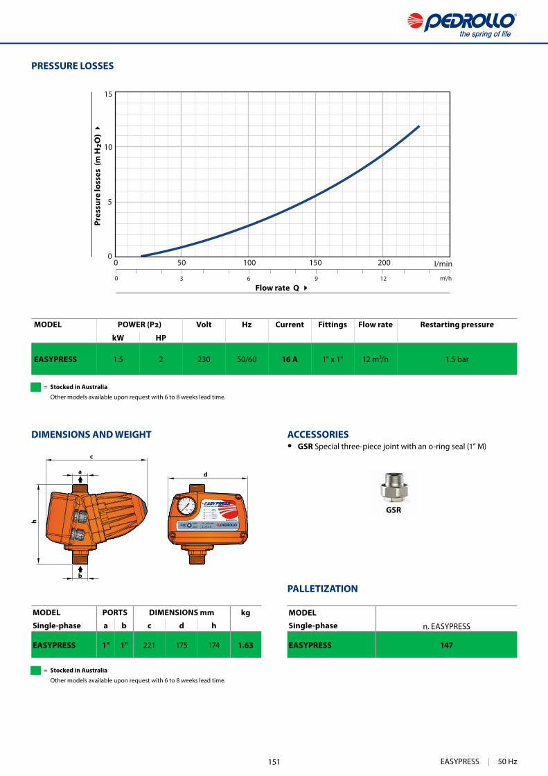
523
2
0 bar
4 6
8
10
5
10
15
0
0 6 1293 m3/h
0 50 l/min100 150 200
GSR
d
c
h
a
b
Flow rate Q
Pres
sure
loss
es (
m H
2O
)
DIMENSIONS AND WEIGHT
PRESSURE LOSSES
ACCESSORIES • GSR Special three-piece joint with an o-ring seal (1” M)
MODEL PORTS DIMENSIONS mm kg
Single-phase a b c d h
EASYPRESS 1" 1" 221 175 174 1.63
MODEL Volt Hz Current Fittings Flow rate Restarting pressure
kW HP
EASYPRESS 1.5 2 230 50/60 16 A 1" x 1" 12 m³/h 1.5 bar
MODELSingle-phase n. EASYPRESS
EASYPRESS 147
PALLETIZATION
EASYPRESS | 50 Hz
= Stocked in Australia
Other models available upon request with 6 to 8 weeks lead time.
= Stocked in Australia
Other models available upon request with 6 to 8 weeks lead time.
151

Related Documents