TECHNICAL SPECIFICATION FOR RATE CONTRACT OF PLATE HEAT EXCHANGERS Specification No. : PE-RC-999-179-N003 (REV 0) BHARAT HEAVY ELECTRICALS LIMITED POWER SECTOR PROJECT ENGINEERING MANAGEMENT NOIDA-201301

Welcome message from author
This document is posted to help you gain knowledge. Please leave a comment to let me know what you think about it! Share it to your friends and learn new things together.
Transcript
TECHNICAL SPECIFICATION FOR
RATE CONTRACT OF
PLATE HEAT EXCHANGERS
Specification No. : PE-RC-999-179-N003 (REV 0)
BHARAT HEAVY ELECTRICALS LIMITED POWER SECTOR
PROJECT ENGINEERING MANAGEMENT NOIDA-201301
TITLE : SPECIFICATION NO. PE-RC-999-179-N003 TECHNICAL SPECIFICATION FOR
RATE CONTRACT OF PLATE HEAT EXCHANGERS SECTION
REV. NO. 0 DATE 22/2/2020
INDEX
This Technical Specification consists of three Sections:
SECTION TITLE SECTION I SPECIFIC TECHNICAL REQUIREMENTS
IA SPECIFIC TECHNICAL REQUIREMENTS. IB DATA SHEET – A.
SECTION II STANDARD TECHNICAL REQUIREMENTS
IIA STANDARD TECHNICAL SPECIFICATION. IIB STANDARD QUALITY PLAN.
SECTION III DOCUMENTS TO BE SUBMITTED BY BIDDER
IIIA COMPLIANCE CERTIFICATE (TO BE SUBMITTED BY BIDDER DURING TENDER STAGE).
IIIB GUARANTEE SCHDULE (TO BE SUBMITTED BY BIDDER DURING TENDER
STAGE). IIIC DATASHEET –B & BALANCE DOCUMENTS AS PER CL. NO. 8 OF SECTION- IA
(TO BE SUBMITTED BY SUCESSFUL BIDDER AFTER AWARD OF CONTRACT). Notes:
1) For detailed list of documents to be submitted by bidder in their technical offer, please refer cl. no. 10.00.00 of Section-IIA.
2) For detailed list of documents to be submitted by vendor after award of contract, please refer Datasheet-C of Section-IIA.
3) In case there is conflict in different clauses of specification, most stringent clause (as
decided by BHEL / end customer) shall be followed, if no specific deviation is taken by bidder and accepted by BHEL during tender stage in that regard.
TITLE : SPECIFICATION NO. PE-RC-999-179-N003 TECHNICAL SPECIFICATION FOR
RATE CONTRACT OF PLATE HEAT EXCHANGERS SECTION I
REV. NO. 0 DATE 22/2/2020
SECTION I
IA SPECIFIC TECHNICAL REQUIREMENTS IB DATASHEET – A
TITLE : SPECIFICATION NO. PE-RC-999-179-N003 TECHNICAL SPECIFICATION FOR
RATE CONTRACT OF PLATE HEAT EXCHANGERS SECTION IA
REV. NO. 0 DATE 22/2/2020
SHEET 1 OF 2
1.0 GENERAL : 1.1 This specification is intended for finalization of rate contract between BHEL PEM and Bidder.
Standard technical detail as indicated in the specification shall be agreed upon between BHEL PEM and Bidder. Project specific technical detail shall be made available to the bidder during the specific project ordering.
1.2 This enquiry covers the design, manufacture, assembly, inspection and testing at
manufacturer’s and/ or his sub-contractors works, painting, proper packing & delivery of the item namely PLATE HEAT EXCHANGERS complete with all spares (as applicable), accessories, commissioning spares (if any), counter flanges with nuts, bolts, gaskets and coatings (wherever necessary), including special tools & tackles (if any), including site PG test (as applicable) as mentioned in this specification.
Note:
1. This specification is being made with the intent of entering into rate contract for the supply of Plate Heat Exchangers (PHEs) of various type applicable for the various projects from time to time.
2. Type of PHEs have been detailed in Data Sheet-A, Section-1B. The bidder shall include complete supplies in his scope. Part supplies offered shall disqualify the bidder's offer. Evaluation shall be combined and further details shall be indicated in NIT.
The Plate heat Exchangers complete with all accessories including special tools and tackles (if any) shall conform to the Data Sheet-A (Section IB) and other requirements of section IIA. In addition, the requirements of this Section IA including Customer Specification attached at Appendix 1 (as applicable) shall also be complied with.
1.3 The bids shall be evaluated as per NIT. Ordering shall be done as per NIT.
1.4 Bidder to quote for items as per price schedule attached in NIT. The quantity as mentioned in the BOQ is only for evaluation purpose. However actual ordered quantity may vary from project to project throughout the year.
2.0 SPECIFIC REQUIREMENTS:
2.1 Project specific requirements for Flow &/ or Temp rise for PHE at primary side as well secondary side may vary slightly vis-à-vis those indicated in Datasheet A at section IB. However Flow variation shall be within +/- 20 % for primary side as well secondary side &/or Temp rise variation shall be within +/- 20 % for primary side as well as secondary side but Heat Load of PHE (Flow x Temp Rise) variation shall be within 0 to +10 % vis-à-vis Flow x Temp Rise as per Datasheet A at section IB. Exact Parameters for specific project shall be informed during project specific order Bidder to meet the above requirement during project specific ordering, without any cost implication to BHEL.
2.2 Design heat load of plate type heat exchangers and Inlet & Outlet temperatures of the Plate
TITLE : SPECIFICATION NO. PE-RC-999-179-N003 TECHNICAL SPECIFICATION FOR
RATE CONTRACT OF PLATE HEAT EXCHANGERS SECTION IA
REV. NO. 0 DATE 22/2/2020
SHEET 2 OF 2
type heat exchangers on the primary and secondary side to be demonstrated at site. Pressure drop across the Plate type heat exchanger on the primary & secondary water circuit to be demonstrated at site. PG test at site (if applicable) as per Project specific requirement shall have to be conducted as per clause 8.02.00 of Section-IIA. Bidder to quote Unit Rate for PG test accordingly.
3.0 The drawing / document submission schedule and delivery shall be as per NIT.
4.0 The Heat transfer plate area measurement procedure and packing procedure indicated at
Section-IIA are only for reference. Project specific procedures shall be submitted by the bidder during detailed engineering for approval.
5.0 Following to be complied by the bidder:
a. Supplier to submit detailed ‘Bill of Material’ (BoM) at the time of drawing/document
submission after placement of PO. Each item of the BoM to be uniquely identified with item code no. or item serial no.
b. Supplier to ensure that all items which will find separate mention in the packing list are covered in this detailed BoM.
c. Supplier to give following undertaking in the BoM” “The BoM provided herewith completes the scope (in content and intent) of material supply under PO no.----------, dated ----------.
Any additional material which may become necessary for the intended application of the supplied items(s)/package will be supplied free of cost in most reasonable time.”
TITLE : SPECIFICATION NO. PE-RC-999-179-N003 TECHNICAL SPECIFICATION FOR
RATE CONTRACT OF PLATE HEAT EXCHANGERS SECTION IA- Appendix 1
REV. NO. 0 DATE 22/02/2020
Appendix 1
CUSTOMER SPECIFICATION
CLAUSE NO. QUALITY ASSURANCE
LOT-3 PROJECTS FLUE GAS DESULPHURISATION (FGD)
SYSTEM PACKAGE
TECHNICAL SPECIFICATION SECTION – VI
BID DOC. NO.:CS-0011-109(3)-9
PART-B SUB-SECTION-V-QM3
EQUIPMENT COOLING WATER SYSTEM
Page 1 of 1
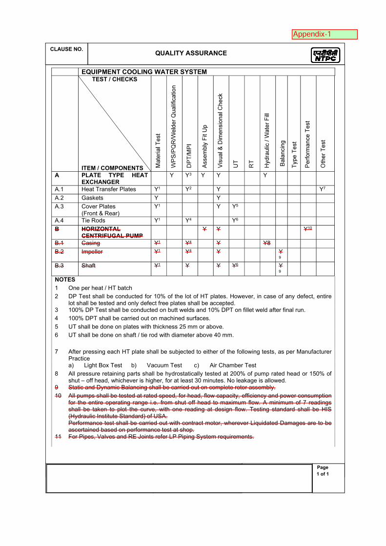
EQUIPMENT COOLING WATER SYSTEM TEST / CHECKS
ITEM / COMPONENTS A PLATE TYPE HEAT
EXCHANGER Y Y3 Y Y Y
A.1 Heat Transfer Plates Y1 Y2 Y Y7
A.2 Gaskets Y Y
A.3 Cover Plates (Front & Rear)
Y1 Y Y5
A.4 Tie Rods Y1 Y4 Y6
B HORIZONTAL CENTRIFUGAL PUMP
Y Y Y10
B.1 Casing Y1 Y4 Y Y8
B.2 Impeller Y1 Y4 Y Y9
B.3 Shaft Y1 Y Y Y6 Y9
NOTES
1 One per heat / HT batch
2 DP Test shall be conducted for 10% of the lot of HT plates. However, in case of any defect, entire lot shall be tested and only defect free plates shall be accepted.
3 100% DP Test shall be conducted on butt welds and 10% DPT on fillet weld after final run.
4 100% DPT shall be carried out on machined surfaces.
5 UT shall be done on plates with thickness 25 mm or above.
6 UT shall be done on shaft / tie rod with diameter above 40 mm.
7 After pressing each HT plate shall be subjected to either of the following tests, as per Manufacturer Practice
a) Light Box Test b) Vacuum Test c) Air Chamber Test
8 All pressure retaining parts shall be hydrostatically tested at 200% of pump rated head or 150% of shut – off head, whichever is higher, for at least 30 minutes. No leakage is allowed.
9 Static and Dynamic Balancing shall be carried out on complete rotor assembly.
10 All pumps shall be tested at rated speed, for head, flow capacity, efficiency and power consumption for the entire operating range i.e. from shut off head to maximum flow. A minimum of 7 readings shall be taken to plot the curve, with one reading at design flow. Testing standard shall be HIS (Hydraulic Institute Standard) of USA. Performance test shall be carried out with contract motor, wherever Liquidated Damages are to be ascertained based on performance test at shop.
11 For Pipes, Valves and RE Joints refer LP Piping System requirements.
Technical specification no PE-RC-999-179-N003 (Rev 0)Section IB
Rev 0Date 25-02-2020
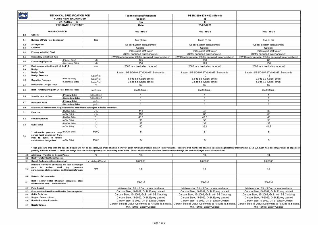
PHE TYPE-1 PHE TYPE-2 PHE TYPE-3
1.0
1.1 Number of Plate Heat Exchanger Nos Four (4) nos Seven (7) nos Five (5) nos
1.2 As per System Requirement As per System Requirement As per System Requirement1.3 Outdoor Outdoor Outdoor
1.4Passivated DM water
(Refer enclosed water analysis)Passivated DM water
(Refer enclosed water analysis)Passivated DM water
(Refer enclosed water analysis)1.5 CW Blowdown water (Refer enclosed water analysis) CW Blowdown water (Refer enclosed water analysis) CW Blowdown water (Refer enclosed water analysis)
(Primary Side) NB 125 100 80(Secondary Side) NB 150 125 100
1.7 mm 2000 mm (excluding reducer) 2000 mm (excluding reducer) 2000 mm (excluding reducer)2.0
2.1 Latest IS/BS/DIN/ASTM/ASME Standards Latest IS/BS/DIN/ASTM/ASME Standards Latest IS/BS/DIN/ASTM/ASME Standards 2.2 Kg/cm2 (g) 10 10 12
(Primary Side) Kg/cm2 (g) 6.5 to 8.5 Kg/sq. cm(g) 6.5 to 8.5 Kg/sq. cm(g) 7.0 to 9.0 Kg/sq. cm(g)(Secondary Side) Kg/cm2 (g) 3.5 to 5.5 Kg/sq. cm(g) 3.5 to 5.5 Kg/sq. cm(g) 5.0 to 7.0 Kg/sq. cm(g)
2.4 oC 60 60 60
2.5 Kcal/Hr./m2 6500 (Max.) 6500 (Max.) 6500 (Max.)
(Primary Side) Cal/gmDeg.C 1 1 1(Secondary Side) Cal/gmDeg.C 1 1 1(Primary Side) gm/cc 1 1 1(Secondary Side) gm/cc 1 1 1
3.0 Guaranteed Performance Requirements for each Heat Exchangers in fouled condition:
(DMCW Side) M3/hr 113 48 36(ACW Side) M3/hr 159 88 63(DMCW Side) oC 43.6 43.6 48(ACW Side) oC 36 36 36(DMCW Side) oC 38 38 38(ACW Side) oC 40 39.1 41.7
(DMCW Side) MWC 5 5 5
(ACW Side) MWC 5 5 5
4.0 Additional HT plates on Design Plates % NIL NIL NIL5.0
5.1 Hr m2deg C/Kcal 0.00008 0.00008 0.00008
5.2 mm 1.6 1.6 1.6
6.0 Material of Construction :
6.1 SS-316 SS-316 SS-316
6.2 Nitrile rubber, 65 ± 5 Deg. shore hardness Nitrile rubber, 65 ± 5 Deg. shore hardness Nitrile rubber, 65 ± 5 Deg. shore hardness6.3 Compression/Fixed/Frame/Movable Pressure plates Carbon Steel, IS-2062, Gr.B, Epoxy painted Carbon Steel, IS-2062, Gr.B, Epoxy painted Carbon Steel, IS-2062, Gr.B, Epoxy painted6.4 Carbon Steel, IS-2062, Gr.B, with SS Cladding Carbon Steel, IS-2062, Gr.B, with SS Cladding Carbon Steel, IS-2062, Gr.B, with SS Cladding6.5 Carbon Steel, IS-2062, Gr.B, Epoxy painted Carbon Steel, IS-2062, Gr.B, Epoxy painted Carbon Steel, IS-2062, Gr.B, Epoxy painted6.6 Carbon steel IS 2062, Gr. B, Epoxy Coated Carbon steel IS 2062, Gr. B, Epoxy Coated Carbon steel IS 2062, Gr. B, Epoxy Coated
6.7Carbon Steel IS 2062 (Confirming to ANSI B 16.5 class,
Min.-150 lb) Epoxy CoatedCarbon Steel IS 2062 (Confirming to ANSI B 16.5 class,
Min.-150 lb) Epoxy CoatedCarbon Steel IS 2062 (Confirming to ANSI B 16.5 class,
Min.-150 lb) Epoxy Coated
Support Beam/ column
Nozzle (Reducer/Expander)
Nozzle flanges
3.3 Outlet temp
3.4
* Allowable pressure dropacross heat exchanger frominlet to outlet in fouledconditions at design flow
Overall fouling resistance (minimun)
Minimum corrosion allowance on heat exchangerparts of carbon steel (e.g. pressureparts,nozzles,sliding channel and frame) (refer note1)
Heat Transfer Coefficient/Margin
2.7 Density of Fluid
3.1 Flow rate
3.2 Inlet temperature
2.3 Operating Pressure
Mechanical Design Temp.
Heat Transfer per Sq.Mtr. Of Heat Transfer Plate
2.6 Specific Heat of Fluid
1.6 Connecting Pipe size
Maximum permitted Length of the PHE
Design
Design Code
Design Pressure
PHE DESCRIPTION
General
Arrangement
Location
Primary side (Hot) Fluid
Secondary side (Cold) fluid
TECHNICAL SPECIFICATION FORPLATE HEAT EXCHANGER
DATASHEET - A FOR RATE CONTRACT
* High pressure drop than the specified figure will not be accepted, no credit shall be, however, given for lower pressure drop in bid evaluation. Pressure drop mentioned shall be calculated against flow mentioned at S. No 3.1. Each heat exchanger shall be capable ofpassing a flow of at least 1.1 times the design flow rate on both primary and secondary water sides. Bidder shall indicate maximum pressure drop through the heat exchanger under this condition.
Heat Transfer Plates (Minimum acceptable platethickness 0.6 mm). Refer Note no. 3
Plate Gasket
Guide Rails/ bar
Page 1 of 2
Technical specification no PE-RC-999-179-N003 (Rev 0)Section IB
Rev 0Date 25-02-2020
PHE TYPE-1 PHE TYPE-2 PHE TYPE-3PHE DESCRIPTION
TECHNICAL SPECIFICATION FORPLATE HEAT EXCHANGER
DATASHEET - A FOR RATE CONTRACT
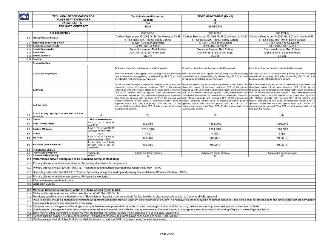
6.8Carbon Steel as per IS 2062 Gr. B (Confirming to ANSI
B 16.5 class, Min.-150 lb) Epoxy CoatedCarbon Steel as per IS 2062 Gr. B (Confirming to ANSI
B 16.5 class, Min.-150 lb) Epoxy CoatedCarbon Steel as per IS 2062 Gr. B (Confirming to ANSI
B 16.5 class, Min.-150 lb) Epoxy Coated6.9 IS-1367 Gr.8.8 or equivalent IS-1367 Gr.8.8 or equivalent IS-1367 Gr.8.8 or equivalent6.10 SA 193 B7/ SA 194 2H SA 193 B7/ SA 194 2H SA 193 B7/ SA 194 2H6.11 3mm wire inserted Red Rubber 3mm wire inserted Red Rubber 3mm wire inserted Red Rubber6.12 AISI 316 18'-8' SS (3 mm thick) AISI 316 18'-8' SS (3 mm thick) AISI 316 18'-8' SS (3 mm thick)6.13 SS-316 SS-316 SS-3166.14
External Surface
a.) Surface Preparation
b.) Primer
c.) Final Paint
7.0 % 25 25 25
8.0 Unit of Measurement
8.11 Lot = 1% of plates ineach PHE
80 LOTS 140 LOTS 100 LOTS
8.21 Lot = 1% of gaskets ofeach type in each PHE
120 LOTS 210 LOTS 150 LOTS
8.3 NOS. 1 NO. 1 NO. 1 NO.
8.41 Lot = 1% of tie-rod ofeach type in each PHE
40 LOTS 70 LOTS 50 LOTS
8.51 Lot = 1% of Nuts & boltsof each type & size ineach PHE
40 LOTS 70 LOTS 50 LOTS
9.09.1 Kg/cm2 (g) 1.5 times the design pressure 1.5 times the design pressure 1.5 times the design pressure 9.2 Minutes 30 30 30
10.0
10.1
10.2
10.3
10.4
10.5
10.6
11.0
11.1
11.2
11.4
11.5
11.6
11.7
11.8
11.3
The plate Heat exchangers shall be single pass type. Heat transfer plates shall be sealed at their outer edges and around the ports by gaskets in order to prevent leakage and inter-mixing of fluids.
Metallurgy specified above is bare minimum . Equivalent or Superior materials suitable for fluid handled is also acceptable subject to Customer/BHEL approval.
Double sealing arrangement shall be provided at outer edge and around ports with the inter space between the seals vented to atmosphere in order to avoid inter-mixing of liquids in case of gaskets failure.Each Plate shall be numbered in sequence with the number marked by indelible ink on each plate to permit easy reassembly.
Painting as specified at Sl. No. 6.14 above shall be subject to customer/BHEL approval during detailed engineering.
Plate thickness should be adequate to withstand all operating conditions but with Minimum plate thickness of 0.6 mm (No negative tolerance allowed in thickness specified). The plates shall be pressed from one single piece with the corrugationbeing smooth, uniform and identical for every plate.
Fasteners (Nuts & bolts etc.)
Duration of Hydrotesting
Performance curves and figures to be furnished during contact stage
Film heat transfer coefficient curve
Minimum Standard requirement of the PHE to be offered by the bidder.Minimum Corrosion allowance on thickness (as per ASME Sec. VIII Div. I)
Correction Curves.
Name Plate
Wetted fasteners
Hydrotesting at Shop Hydrotesting Pressure
Painting
All surface other than stainless steels shall be painted.
The steel surface to be applied with painting shall be thoroughlycleaned before applying painting by shotblasting (SA 2.5) etc shallbe subjected to BHEL/Customer approval.
For all the steel surfaces, a coat of chlorinated rubber based zincphosphate primer of minimum thickness DFT of 50 micronsfollowed up with undercoat of chlorinated rubber paint of minimumDFT of 50 microns shall be applied. Then, intermediate coatconsisting of one coat of chlorinated rubber based paint pigmentedwith Titanium di-oxide with minimum DFT of 50 microns andtopcoat consisting of two coats of chlorinated rubber paint ofapproved shade and color with glossy finish and DFT of 100microns shall be provided. Total DFT of paint system shall not beless than 200 microns.
Heat Transfer Plates
Gaskets (All types)
Valves
Tie Rods
All surface other than stainless steels shall be painted.
The steel surface to be applied with painting shall be thoroughlycleaned before applying painting by shotblasting (SA 2.5) etc shallbe subjected to BHEL/Customer approval.
For all the steel surfaces, a coat of chlorinated rubber based zincphosphate primer of minimum thickness DFT of 50 micronsfollowed up with undercoat of chlorinated rubber paint of minimumDFT of 50 microns shall be applied. Then, intermediate coatconsisting of one coat of chlorinated rubber based paint pigmentedwith Titanium di-oxide with minimum DFT of 50 microns andtopcoat consisting of two coats of chlorinated rubber paint ofapproved shade and color with glossy finish and DFT of 100microns shall be provided. Total DFT of paint system shall not beless than 200 microns.
Extra Carrying capacity to be provided on frame assembly.Spares
Flange/ Counter flanges
Tightening Bolts/Rods & Nuts
Nozzle flange bolts / nuts
Nozzle flange gasket
Flanges shall be as per ANSI 16.5 or equivalent. Thickness of pressure and frame plates shall be as per ASME Sect. VIII div.1.
All surface other than stainless steels shall be painted.
The steel surface to be applied with painting shall be thoroughlycleaned before applying painting by shotblasting (SA 2.5) etc shallbe subjected to BHEL/Customer approval.
For all the steel surfaces, a coat of chlorinated rubber based zincphosphate primer of minimum thickness DFT of 50 micronsfollowed up with undercoat of chlorinated rubber paint of minimumDFT of 50 microns shall be applied. Then, intermediate coatconsisting of one coat of chlorinated rubber based paint pigmentedwith Titanium di-oxide with minimum DFT of 50 microns andtopcoat consisting of two coats of chlorinated rubber paint ofapproved shade and color with glossy finish and DFT of 100microns shall be provided. Total DFT of paint system shall not beless than 200 microns.
Primary side water outlet temperature vs. Secondary side water inlet temperature.
Primary side water flow (80% to 115%) vs. Pressure drop and outlet temperature (Secondary side flow – 100%)
Secondary side water flow (80% to 115%) vs. Secondary side pressure drop and primary side outlet temp (Primary side flow – 100%)
Primary side water outlet temperature vs. Primary side inlet temp.
Page 2 of 2

Technical specification no PE-RC-999-179-N003 (Rev 0)Section IB
Rev 0Date 25-02-2020
PHE TYPE-4 PHE TYPE-5 PHE TYPE-6
1.0
1.1 Number of Plate Heat Exchanger Nos Three (3) nos Eight (8) nos Four (4) nos
1.2 As per System Requirement As per System Requirement As per System Requirement1.3 Outdoor Outdoor Outdoor
1.4Passivated DM water
(Refer enclosed water analysis)Passivated DM water
(Refer enclosed water analysis)Passivated DM water
(Refer enclosed water analysis)1.5 CW Blowdown water (Refer enclosed water analysis) CW Blowdown water (Refer enclosed water analysis) CW Blowdown water (Refer enclosed water analysis)
(Primary Side) NB 100 150 125(Secondary Side) NB 100 150 150
1.7 mm 2000 mm (excluding reducer) 2000 mm (excluding reducer) 2000 mm (excluding reducer)2.0
2.1 Latest IS/BS/DIN/ASTM/ASME Standards Latest IS/BS/DIN/ASTM/ASME Standards Latest IS/BS/DIN/ASTM/ASME Standards 2.2 Kg/cm2 (g) 10 10 10
(Primary Side) Kg/cm2 (g) 5.5 to 7.0 Kg/sq. cm(g) 6.5 to 8.5 Kg/sq. cm(g) 6.5 to 8.5 Kg/sq. cm(g)(Secondary Side) Kg/cm2 (g) 2.5 to 4.0 Kg/sq. cm(g) 4.0 to 6.0 Kg/sq. cm(g) 3.5 to 5.5 Kg/sq. cm(g)
2.4 oC 60 60 60
2.5 Kcal/Hr./m2 6500 (Max.) 6500 (Max.) 6500 (Max.)
(Primary Side) Cal/gmDeg.C 1 1 1(Secondary Side) Cal/gmDeg.C 1 1 1(Primary Side) gm/cc 1 1 1(Secondary Side) gm/cc 1 1 1
3.0 Guaranteed Performance Requirements for each Heat Exchangers in fouled condition:
(DMCW Side) M3/hr 40 80 113(ACW Side) M3/hr 62 95 159(DMCW Side) oC 48 48 48(ACW Side) oC 36 36 36(DMCW Side) oC 38 38 38(ACW Side) oC 42.5 44.4 43.1
(DMCW Side) MWC 5 5 5
(ACW Side) MWC 5 5 5
4.0 Additional HT plates on Design Plates % NIL NIL NIL5.0
5.1 Hr m2deg C/Kcal 0.00008 0.00008 0.00008
5.2 mm 1.6 1.6 1.6
6.0 Material of Construction :
6.1 SS-316 SS-316 SS-316
6.2 Nitrile rubber, 65 ± 5 Deg. shore hardness Nitrile rubber, 65 ± 5 Deg. shore hardness Nitrile rubber, 65 ± 5 Deg. shore hardness6.3 Compression/Fixed/Frame/Movable Pressure plates Carbon Steel, IS-2062, Gr.B, Epoxy painted Carbon Steel, IS-2062, Gr.B, Epoxy painted Carbon Steel, IS-2062, Gr.B, Epoxy painted6.4 Carbon Steel, IS-2062, Gr.B, with SS Cladding Carbon Steel, IS-2062, Gr.B, with SS Cladding Carbon Steel, IS-2062, Gr.B, with SS Cladding6.5 Carbon Steel, IS-2062, Gr.B, Epoxy painted Carbon Steel, IS-2062, Gr.B, Epoxy painted Carbon Steel, IS-2062, Gr.B, Epoxy painted6.6 Carbon steel IS 2062, Gr. B, Epoxy Coated Carbon steel IS 2062, Gr. B, Epoxy Coated Carbon steel IS 2062, Gr. B, Epoxy Coated
6.7Carbon Steel IS 2062 (Confirming to ANSI B 16.5 class,
Min.-150 lb) Epoxy CoatedCarbon Steel IS 2062 (Confirming to ANSI B 16.5 class,
Min.-150 lb) Epoxy CoatedCarbon Steel IS 2062 (Confirming to ANSI B 16.5 class,
Min.-150 lb) Epoxy Coated
Nozzle (Reducer/Expander)
Nozzle flanges
Overall fouling resistance (minimun)
Minimum corrosion allowance on heat exchangerparts of carbon steel (e.g. pressureparts,nozzles,sliding channel and frame) (refer note1)
Heat Transfer Plates (Minimum acceptable platethickness 0.6 mm). Refer Note no. 3
Plate Gasket
Guide Rails/ bar
Support Beam/ column
3.3 Outlet temp
3.4
* Allowable pressure dropacross heat exchanger frominlet to outlet in fouledconditions at design flow
* High pressure drop than the specified figure will not be accepted, no credit shall be, however, given for lower pressure drop in bid evaluation. Pressure drop mentioned shall be calculated against flow mentioned at S. No 3.1. Each heat exchanger shall be capable ofpassing a flow of at least 1.1 times the design flow rate on both primary and secondary water sides. Bidder shall indicate maximum pressure drop through the heat exchanger under this condition.
Heat Transfer Coefficient/Margin
2.7 Density of Fluid
3.1 Flow rate
3.2 Inlet temperature
2.3 Operating Pressure
Mechanical Design Temp.
Heat Transfer per Sq.Mtr. Of Heat Transfer Plate
2.6 Specific Heat of Fluid
1.6 Connecting Pipe size
Maximum permitted Length of the PHE
Design
Design Code
Design Pressure
PHE DESCRIPTION
General
Arrangement
Location
Primary side (Hot) Fluid
Secondary side (Cold) fluid
TECHNICAL SPECIFICATION FORPLATE HEAT EXCHANGER
DATASHEET - A FOR RATE CONTRACT
Page 1 of 2

Technical specification no PE-RC-999-179-N003 (Rev 0)Section IB
Rev 0Date 25-02-2020
PHE TYPE-4 PHE TYPE-5 PHE TYPE-6PHE DESCRIPTION
TECHNICAL SPECIFICATION FORPLATE HEAT EXCHANGER
DATASHEET - A FOR RATE CONTRACT
6.8Carbon Steel as per IS 2062 Gr. B (Confirming to ANSI
B 16.5 class, Min.-150 lb) Epoxy CoatedCarbon Steel as per IS 2062 Gr. B (Confirming to ANSI
B 16.5 class, Min.-150 lb) Epoxy CoatedCarbon Steel as per IS 2062 Gr. B (Confirming to ANSI
B 16.5 class, Min.-150 lb) Epoxy Coated6.9 IS-1367 Gr.8.8 or equivalent IS-1367 Gr.8.8 or equivalent IS-1367 Gr.8.8 or equivalent6.10 SA 193 B7/ SA 194 2H SA 193 B7/ SA 194 2H SA 193 B7/ SA 194 2H6.11 3mm wire inserted Red Rubber 3mm wire inserted Red Rubber 3mm wire inserted Red Rubber6.12 AISI 316 18'-8' SS (3 mm thick) AISI 316 18'-8' SS (3 mm thick) AISI 316 18'-8' SS (3 mm thick)6.13 SS-316 SS-316 SS-3166.14
External Surface
a.) Surface Preparation
b.) Primer
c.) Final Paint
7.0 % 25 25 25
8.0 Unit of Measurement
8.11 Lot = 1% of plates ineach PHE
60 LOTS 160 LOTS 80 LOTS
8.21 Lot = 1% of gaskets ofeach type in each PHE
90 LOTS 240 LOTS 120 LOTS
8.3 NOS. 1 NO. 1 NO. 1 NO.
8.41 Lot = 1% of tie-rod ofeach type in each PHE
30 LOTS 80 LOTS 40 LOTS
8.51 Lot = 1% of Nuts & boltsof each type & size ineach PHE
30 LOTS 80 LOTS 40 LOTS
9.09.1 Kg/cm2 (g) 1.5 times the design pressure 1.5 times the design pressure 1.5 times the design pressure 9.2 Minutes 30 30 30
10.0
10.1
10.2
10.3
10.4
10.5
10.6
11.0
11.1
11.2
11.4
11.5
11.6
11.7
11.8
Each Plate shall be numbered in sequence with the number marked by indelible ink on each plate to permit easy reassembly. Flanges shall be as per ANSI 16.5 or equivalent. Thickness of pressure and frame plates shall be as per ASME Sect. VIII div.1. Painting as specified at Sl. No. 6.14 above shall be subject to customer/BHEL approval during detailed engineering.
Minimum Corrosion allowance on thickness (as per ASME Sec. VIII Div. I)Metallurgy specified above is bare minimum . Equivalent or Superior materials suitable for fluid handled is also acceptable subject to Customer/BHEL approval.
11.3Plate thickness should be adequate to withstand all operating conditions but with Minimum plate thickness of 0.6 mm (No negative tolerance allowed in thickness specified). The plates shall be pressed from one single piece with the corrugationbeing smooth, uniform and identical for every plate. The plate Heat exchangers shall be single pass type. Heat transfer plates shall be sealed at their outer edges and around the ports by gaskets in order to prevent leakage and inter-mixing of fluids.Double sealing arrangement shall be provided at outer edge and around ports with the inter space between the seals vented to atmosphere in order to avoid inter-mixing of liquids in case of gaskets failure.
Primary side water flow (80% to 115%) vs. Pressure drop and outlet temperature (Secondary side flow – 100%)
Secondary side water flow (80% to 115%) vs. Secondary side pressure drop and primary side outlet temp (Primary side flow – 100%)
Primary side water outlet temperature vs. Primary side inlet temp.
Film heat transfer coefficient curve
Correction Curves.
Minimum Standard requirement of the PHE to be offered by the bidder.
Fasteners (Nuts & bolts etc.)
Hydrotesting at Shop Hydrotesting PressureDuration of Hydrotesting
Performance curves and figures to be furnished during contact stage
Primary side water outlet temperature vs. Secondary side water inlet temperature.
Extra Carrying capacity to be provided on frame assembly.Spares
Heat Transfer Plates
Gaskets (All types)
Valves
Tie Rods
Name Plate
Wetted fasteners
Painting
All surface other than stainless steels shall be painted.
The steel surface to be applied with painting shall be thoroughlycleaned before applying painting by shotblasting (SA 2.5) etc shallbe subjected to BHEL/Customer approval.
For all the steel surfaces, a coat of chlorinated rubber based zincphosphate primer of minimum thickness DFT of 50 micronsfollowed up with undercoat of chlorinated rubber paint of minimumDFT of 50 microns shall be applied. Then, intermediate coatconsisting of one coat of chlorinated rubber based paint pigmentedwith Titanium di-oxide with minimum DFT of 50 microns andtopcoat consisting of two coats of chlorinated rubber paint ofapproved shade and color with glossy finish and DFT of 100microns shall be provided. Total DFT of paint system shall not beless than 200 microns.
Flange/ Counter flanges
Tightening Bolts/Rods & Nuts
Nozzle flange bolts / nuts
Nozzle flange gasket
Page 2 of 2

Technical specification no PE-RC-999-179-N003 (Rev 0)Section IB
Rev 0Date 25-02-2020
PHE TYPE-7 PHE TYPE-8 PHE TYPE-9
1.0
1.1 Number of Plate Heat Exchanger Nos Seven (7) nos Five (5) nos Three (3) nos
1.2 As per System Requirement As per System Requirement As per System Requirement1.3 Outdoor Outdoor Outdoor
1.4Passivated DM water
(Refer enclosed water analysis)Passivated DM water
(Refer enclosed water analysis)Passivated DM water
(Refer enclosed water analysis)1.5 CW Blowdown water (Refer enclosed water analysis) CW Blowdown water (Refer enclosed water analysis) CW Blowdown water (Refer enclosed water analysis)
(Primary Side) NB 100 80 100(Secondary Side) NB 125 100 100
1.7 mm 2000 mm (excluding reducer) 2000 mm (excluding reducer) 2000 mm (excluding reducer)2.0
2.1 Latest IS/BS/DIN/ASTM/ASME Standards Latest IS/BS/DIN/ASTM/ASME Standards Latest IS/BS/DIN/ASTM/ASME Standards 2.2 Kg/cm2 (g) 10 12 10
(Primary Side) Kg/cm2 (g) 6.5 to 8.5 Kg/sq. cm(g) 7.0 to 9.0 Kg/sq. cm(g) 5.5 to 7.0 Kg/sq. cm(g)(Secondary Side) Kg/cm2 (g) 3.5 to 5.5 Kg/sq. cm(g) 5.0 to 7.0 Kg/sq. cm(g) 2.5 to 4.0 Kg/sq. cm(g)
2.4 oC 60 60 60
2.5 Kcal/Hr./m2 6500 (Max.) 6500 (Max.) 6500 (Max.)
(Primary Side) Cal/gmDeg.C 1 1 1(Secondary Side) Cal/gmDeg.C 1 1 1(Primary Side) gm/cc 1 1 1(Secondary Side) gm/cc 1 1 1
3.0 Guaranteed Performance Requirements for each Heat Exchangers in fouled condition:
(DMCW Side) M3/hr 48 36 40(ACW Side) M3/hr 88 63 62(DMCW Side) oC 48 43.6 43.6(ACW Side) oC 36 36 36(DMCW Side) oC 38 38 38(ACW Side) oC 41.5 39.2 39.6
(DMCW Side) MWC 5 5 5
(ACW Side) MWC 5 5 5
4.0 Additional HT plates on Design Plates % NIL NIL NIL5.0
5.1 Hr m2deg C/Kcal 0.00008 0.00008 0.00008
5.2 mm 1.6 1.6 1.6
6.0 Material of Construction :
6.1 SS-316 SS-316 SS-316
6.2 Nitrile rubber, 65 ± 5 Deg. shore hardness Nitrile rubber, 65 ± 5 Deg. shore hardness Nitrile rubber, 65 ± 5 Deg. shore hardness6.3 Compression/Fixed/Frame/Movable Pressure plates Carbon Steel, IS-2062, Gr.B, Epoxy painted Carbon Steel, IS-2062, Gr.B, Epoxy painted Carbon Steel, IS-2062, Gr.B, Epoxy painted6.4 Carbon Steel, IS-2062, Gr.B, with SS Cladding Carbon Steel, IS-2062, Gr.B, with SS Cladding Carbon Steel, IS-2062, Gr.B, with SS Cladding6.5 Carbon Steel, IS-2062, Gr.B, Epoxy painted Carbon Steel, IS-2062, Gr.B, Epoxy painted Carbon Steel, IS-2062, Gr.B, Epoxy painted6.6 Carbon steel IS 2062, Gr. B, Epoxy Coated Carbon steel IS 2062, Gr. B, Epoxy Coated Carbon steel IS 2062, Gr. B, Epoxy Coated
6.7Carbon Steel IS 2062 (Confirming to ANSI B 16.5 class,
Min.-150 lb) Epoxy CoatedCarbon Steel IS 2062 (Confirming to ANSI B 16.5 class,
Min.-150 lb) Epoxy CoatedCarbon Steel IS 2062 (Confirming to ANSI B 16.5 class,
Min.-150 lb) Epoxy Coated
Nozzle (Reducer/Expander)
Nozzle flanges
Overall fouling resistance (minimun)
Minimum corrosion allowance on heat exchangerparts of carbon steel (e.g. pressureparts,nozzles,sliding channel and frame) (refer note1)
Heat Transfer Plates (Minimum acceptable platethickness 0.6 mm). Refer Note no. 3
Plate Gasket
Guide Rails/ bar
Support Beam/ column
3.3 Outlet temp
3.4
* Allowable pressure dropacross heat exchanger frominlet to outlet in fouledconditions at design flow
* High pressure drop than the specified figure will not be accepted, no credit shall be, however, given for lower pressure drop in bid evaluation. Pressure drop mentioned shall be calculated against flow mentioned at S. No 3.1. Each heat exchanger shall be capable ofpassing a flow of at least 1.1 times the design flow rate on both primary and secondary water sides. Bidder shall indicate maximum pressure drop through the heat exchanger under this condition.
Heat Transfer Coefficient/Margin
2.7 Density of Fluid
3.1 Flow rate
3.2 Inlet temperature
2.3 Operating Pressure
Mechanical Design Temp.
Heat Transfer per Sq.Mtr. Of Heat Transfer Plate
2.6 Specific Heat of Fluid
1.6 Connecting Pipe size
Maximum permitted Length of the PHE
Design
Design Code
Design Pressure
PHE DESCRIPTION
General
Arrangement
Location
Primary side (Hot) Fluid
Secondary side (Cold) fluid
TECHNICAL SPECIFICATION FORPLATE HEAT EXCHANGER
DATASHEET - A FOR RATE CONTRACT
Page 1 of 2
Technical specification no PE-RC-999-179-N003 (Rev 0)Section IB
Rev 0Date 25-02-2020
PHE TYPE-7 PHE TYPE-8 PHE TYPE-9PHE DESCRIPTION
TECHNICAL SPECIFICATION FORPLATE HEAT EXCHANGER
DATASHEET - A FOR RATE CONTRACT
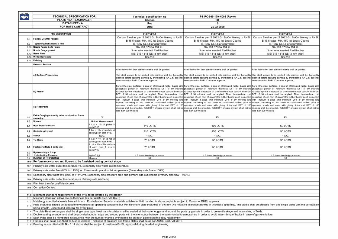
6.8Carbon Steel as per IS 2062 Gr. B (Confirming to ANSI
B 16.5 class, Min.-150 lb) Epoxy CoatedCarbon Steel as per IS 2062 Gr. B (Confirming to ANSI
B 16.5 class, Min.-150 lb) Epoxy CoatedCarbon Steel as per IS 2062 Gr. B (Confirming to ANSI
B 16.5 class, Min.-150 lb) Epoxy Coated6.9 IS-1367 Gr.8.8 or equivalent IS-1367 Gr.8.8 or equivalent IS-1367 Gr.8.8 or equivalent6.10 SA 193 B7/ SA 194 2H SA 193 B7/ SA 194 2H SA 193 B7/ SA 194 2H6.11 3mm wire inserted Red Rubber 3mm wire inserted Red Rubber 3mm wire inserted Red Rubber6.12 AISI 316 18'-8' SS (3 mm thick) AISI 316 18'-8' SS (3 mm thick) AISI 316 18'-8' SS (3 mm thick)6.13 SS-316 SS-316 SS-3166.14
External Surface
a.) Surface Preparation
b.) Primer
c.) Final Paint
7.0 % 25 25 25
8.0 Unit of Measurement
8.11 Lot = 1% of plates ineach PHE
140 LOTS 100 LOTS 60 LOTS
8.21 Lot = 1% of gaskets ofeach type in each PHE
210 LOTS 150 LOTS 90 LOTS
8.3 NOS. 1 NO. 1 NO. 1 NO.
8.41 Lot = 1% of tie-rod ofeach type in each PHE
70 LOTS 50 LOTS 30 LOTS
8.51 Lot = 1% of Nuts & boltsof each type & size ineach PHE
70 LOTS 50 LOTS 30 LOTS
9.09.1 Kg/cm2 (g) 1.5 times the design pressure 1.5 times the design pressure 1.5 times the design pressure 9.2 Minutes 30 30 30
10.0
10.1
10.2
10.3
10.4
10.5
10.6
11.0
11.1
11.2
11.4
11.5
11.6
11.7
11.8
Each Plate shall be numbered in sequence with the number marked by indelible ink on each plate to permit easy reassembly. Flanges shall be as per ANSI 16.5 or equivalent. Thickness of pressure and frame plates shall be as per ASME Sect. VIII div.1. Painting as specified at Sl. No. 6.14 above shall be subject to customer/BHEL approval during detailed engineering.
Minimum Corrosion allowance on thickness (as per ASME Sec. VIII Div. I)Metallurgy specified above is bare minimum . Equivalent or Superior materials suitable for fluid handled is also acceptable subject to Customer/BHEL approval.
11.3Plate thickness should be adequate to withstand all operating conditions but with Minimum plate thickness of 0.6 mm (No negative tolerance allowed in thickness specified). The plates shall be pressed from one single piece with the corrugationbeing smooth, uniform and identical for every plate. The plate Heat exchangers shall be single pass type. Heat transfer plates shall be sealed at their outer edges and around the ports by gaskets in order to prevent leakage and inter-mixing of fluids.Double sealing arrangement shall be provided at outer edge and around ports with the inter space between the seals vented to atmosphere in order to avoid inter-mixing of liquids in case of gaskets failure.
Primary side water flow (80% to 115%) vs. Pressure drop and outlet temperature (Secondary side flow – 100%)
Secondary side water flow (80% to 115%) vs. Secondary side pressure drop and primary side outlet temp (Primary side flow – 100%)
Primary side water outlet temperature vs. Primary side inlet temp.
Film heat transfer coefficient curve
Correction Curves.
Minimum Standard requirement of the PHE to be offered by the bidder.
Fasteners (Nuts & bolts etc.)
Hydrotesting at Shop Hydrotesting PressureDuration of Hydrotesting
Performance curves and figures to be furnished during contact stage
Primary side water outlet temperature vs. Secondary side water inlet temperature.
Extra Carrying capacity to be provided on frame assembly.Spares
Heat Transfer Plates
Gaskets (All types)
Valves
Tie Rods
Name Plate
Wetted fasteners
Painting
All surface other than stainless steels shall be painted.
The steel surface to be applied with painting shall be thoroughlycleaned before applying painting by shotblasting (SA 2.5) etc shallbe subjected to BHEL/Customer approval.
For all the steel surfaces, a coat of chlorinated rubber based zincphosphate primer of minimum thickness DFT of 50 micronsfollowed up with undercoat of chlorinated rubber paint of minimumDFT of 50 microns shall be applied. Then, intermediate coatconsisting of one coat of chlorinated rubber based paint pigmentedwith Titanium di-oxide with minimum DFT of 50 microns andtopcoat consisting of two coats of chlorinated rubber paint ofapproved shade and color with glossy finish and DFT of 100microns shall be provided. Total DFT of paint system shall not beless than 200 microns.
All surface other than stainless steels shall be painted.
The steel surface to be applied with painting shall be thoroughlycleaned before applying painting by shotblasting (SA 2.5) etc shallbe subjected to BHEL/Customer approval.
For all the steel surfaces, a coat of chlorinated rubber based zincphosphate primer of minimum thickness DFT of 50 micronsfollowed up with undercoat of chlorinated rubber paint of minimumDFT of 50 microns shall be applied. Then, intermediate coatconsisting of one coat of chlorinated rubber based paint pigmentedwith Titanium di-oxide with minimum DFT of 50 microns andtopcoat consisting of two coats of chlorinated rubber paint ofapproved shade and color with glossy finish and DFT of 100microns shall be provided. Total DFT of paint system shall not beless than 200 microns.
All surface other than stainless steels shall be painted.
The steel surface to be applied with painting shall be thoroughlycleaned before applying painting by shotblasting (SA 2.5) etc shallbe subjected to BHEL/Customer approval.
For all the steel surfaces, a coat of chlorinated rubber based zincphosphate primer of minimum thickness DFT of 50 micronsfollowed up with undercoat of chlorinated rubber paint of minimumDFT of 50 microns shall be applied. Then, intermediate coatconsisting of one coat of chlorinated rubber based paint pigmentedwith Titanium di-oxide with minimum DFT of 50 microns andtopcoat consisting of two coats of chlorinated rubber paint ofapproved shade and color with glossy finish and DFT of 100microns shall be provided. Total DFT of paint system shall not beless than 200 microns.
Flange/ Counter flanges
Tightening Bolts/Rods & Nuts
Nozzle flange bolts / nuts
Nozzle flange gasket
Page 2 of 2
Technical specification no PE-RC-999-179-N003 (Rev 0)Section IB
Rev 0Date 25-02-2020
PHE TYPE-10 PHE TYPE-11 PHE TYPE-12
1.0
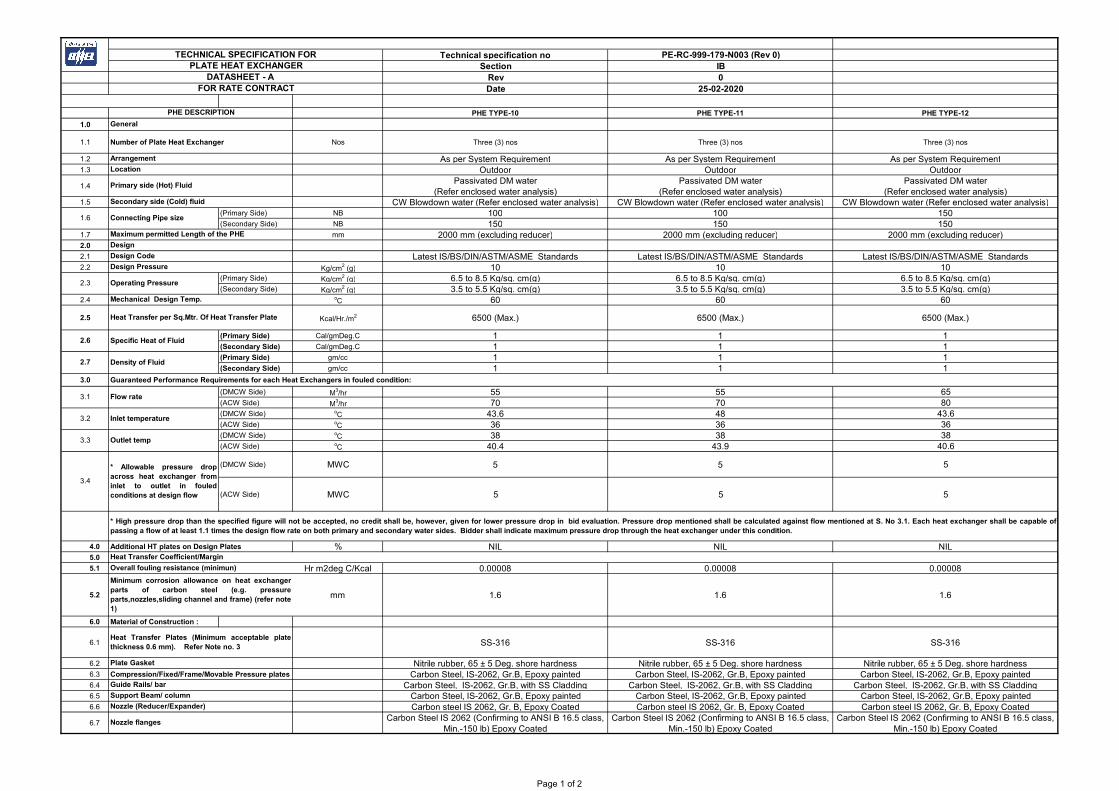
1.1 Number of Plate Heat Exchanger Nos Three (3) nos Three (3) nos Three (3) nos
1.2 As per System Requirement As per System Requirement As per System Requirement1.3 Outdoor Outdoor Outdoor
1.4Passivated DM water
(Refer enclosed water analysis)Passivated DM water
(Refer enclosed water analysis)Passivated DM water
(Refer enclosed water analysis)1.5 CW Blowdown water (Refer enclosed water analysis) CW Blowdown water (Refer enclosed water analysis) CW Blowdown water (Refer enclosed water analysis)
(Primary Side) NB 100 100 150(Secondary Side) NB 150 150 150
1.7 mm 2000 mm (excluding reducer) 2000 mm (excluding reducer) 2000 mm (excluding reducer)2.0
2.1 Latest IS/BS/DIN/ASTM/ASME Standards Latest IS/BS/DIN/ASTM/ASME Standards Latest IS/BS/DIN/ASTM/ASME Standards 2.2 Kg/cm2 (g) 10 10 10
(Primary Side) Kg/cm2 (g) 6.5 to 8.5 Kg/sq. cm(g) 6.5 to 8.5 Kg/sq. cm(g) 6.5 to 8.5 Kg/sq. cm(g)(Secondary Side) Kg/cm2 (g) 3.5 to 5.5 Kg/sq. cm(g) 3.5 to 5.5 Kg/sq. cm(g) 3.5 to 5.5 Kg/sq. cm(g)
2.4 oC 60 60 60
2.5 Kcal/Hr./m2 6500 (Max.) 6500 (Max.) 6500 (Max.)
(Primary Side) Cal/gmDeg.C 1 1 1(Secondary Side) Cal/gmDeg.C 1 1 1(Primary Side) gm/cc 1 1 1(Secondary Side) gm/cc 1 1 1
3.0 Guaranteed Performance Requirements for each Heat Exchangers in fouled condition:
(DMCW Side) M3/hr 55 55 65(ACW Side) M3/hr 70 70 80(DMCW Side) oC 43.6 48 43.6(ACW Side) oC 36 36 36(DMCW Side) oC 38 38 38(ACW Side) oC 40.4 43.9 40.6
(DMCW Side) MWC 5 5 5
(ACW Side) MWC 5 5 5
4.0 Additional HT plates on Design Plates % NIL NIL NIL5.0
5.1 Hr m2deg C/Kcal 0.00008 0.00008 0.00008
5.2 mm 1.6 1.6 1.6
6.0 Material of Construction :
6.1 SS-316 SS-316 SS-316
6.2 Nitrile rubber, 65 ± 5 Deg. shore hardness Nitrile rubber, 65 ± 5 Deg. shore hardness Nitrile rubber, 65 ± 5 Deg. shore hardness6.3 Compression/Fixed/Frame/Movable Pressure plates Carbon Steel, IS-2062, Gr.B, Epoxy painted Carbon Steel, IS-2062, Gr.B, Epoxy painted Carbon Steel, IS-2062, Gr.B, Epoxy painted6.4 Carbon Steel, IS-2062, Gr.B, with SS Cladding Carbon Steel, IS-2062, Gr.B, with SS Cladding Carbon Steel, IS-2062, Gr.B, with SS Cladding6.5 Carbon Steel, IS-2062, Gr.B, Epoxy painted Carbon Steel, IS-2062, Gr.B, Epoxy painted Carbon Steel, IS-2062, Gr.B, Epoxy painted6.6 Carbon steel IS 2062, Gr. B, Epoxy Coated Carbon steel IS 2062, Gr. B, Epoxy Coated Carbon steel IS 2062, Gr. B, Epoxy Coated
6.7Carbon Steel IS 2062 (Confirming to ANSI B 16.5 class,
Min.-150 lb) Epoxy CoatedCarbon Steel IS 2062 (Confirming to ANSI B 16.5 class,
Min.-150 lb) Epoxy CoatedCarbon Steel IS 2062 (Confirming to ANSI B 16.5 class,
Min.-150 lb) Epoxy Coated
Nozzle (Reducer/Expander)
Nozzle flanges
Overall fouling resistance (minimun)
Minimum corrosion allowance on heat exchangerparts of carbon steel (e.g. pressureparts,nozzles,sliding channel and frame) (refer note1)
Heat Transfer Plates (Minimum acceptable platethickness 0.6 mm). Refer Note no. 3
Plate Gasket
Guide Rails/ bar
Support Beam/ column
3.3 Outlet temp
3.4
* Allowable pressure dropacross heat exchanger frominlet to outlet in fouledconditions at design flow
* High pressure drop than the specified figure will not be accepted, no credit shall be, however, given for lower pressure drop in bid evaluation. Pressure drop mentioned shall be calculated against flow mentioned at S. No 3.1. Each heat exchanger shall be capable ofpassing a flow of at least 1.1 times the design flow rate on both primary and secondary water sides. Bidder shall indicate maximum pressure drop through the heat exchanger under this condition.
Heat Transfer Coefficient/Margin
2.7 Density of Fluid
3.1 Flow rate
3.2 Inlet temperature
2.3 Operating Pressure
Mechanical Design Temp.
Heat Transfer per Sq.Mtr. Of Heat Transfer Plate
2.6 Specific Heat of Fluid
1.6 Connecting Pipe size
Maximum permitted Length of the PHE
Design
Design Code
Design Pressure
PHE DESCRIPTION
General
Arrangement
Location
Primary side (Hot) Fluid
Secondary side (Cold) fluid
TECHNICAL SPECIFICATION FORPLATE HEAT EXCHANGER
DATASHEET - A FOR RATE CONTRACT
Page 1 of 2

Technical specification no PE-RC-999-179-N003 (Rev 0)Section IB
Rev 0Date 25-02-2020
PHE TYPE-10 PHE TYPE-11 PHE TYPE-12PHE DESCRIPTION
TECHNICAL SPECIFICATION FORPLATE HEAT EXCHANGER
DATASHEET - A FOR RATE CONTRACT
6.8Carbon Steel as per IS 2062 Gr. B (Confirming to ANSI
B 16.5 class, Min.-150 lb) Epoxy CoatedCarbon Steel as per IS 2062 Gr. B (Confirming to ANSI
B 16.5 class, Min.-150 lb) Epoxy CoatedCarbon Steel as per IS 2062 Gr. B (Confirming to ANSI
B 16.5 class, Min.-150 lb) Epoxy Coated6.9 IS-1367 Gr.8.8 or equivalent IS-1367 Gr.8.8 or equivalent IS-1367 Gr.8.8 or equivalent6.10 SA 193 B7/ SA 194 2H SA 193 B7/ SA 194 2H SA 193 B7/ SA 194 2H6.11 3mm wire inserted Red Rubber 3mm wire inserted Red Rubber 3mm wire inserted Red Rubber6.12 AISI 316 18'-8' SS (3 mm thick) AISI 316 18'-8' SS (3 mm thick) AISI 316 18'-8' SS (3 mm thick)6.13 SS-316 SS-316 SS-3166.14
External Surface
a.) Surface Preparation
b.) Primer
c.) Final Paint
7.0 % 25 25 25
8.0 Unit of Measurement
8.11 Lot = 1% of plates ineach PHE
60 LOTS 60 LOTS 60 LOTS
8.21 Lot = 1% of gaskets ofeach type in each PHE
90 LOTS 90 LOTS 90 LOTS
8.3 NOS. 1 NO. 1 NO. 1 NO.
8.41 Lot = 1% of tie-rod ofeach type in each PHE
30 LOTS 30 LOTS 30 LOTS
8.51 Lot = 1% of Nuts & boltsof each type & size ineach PHE
30 LOTS 30 LOTS 30 LOTS
9.09.1 Kg/cm2 (g) 1.5 times the design pressure 1.5 times the design pressure 1.5 times the design pressure 9.2 Minutes 30 30 30
10.0
10.1
10.2
10.3
10.4
10.5
10.6
11.0
11.1
11.2
11.4
11.5
11.6
11.7
11.8
Each Plate shall be numbered in sequence with the number marked by indelible ink on each plate to permit easy reassembly. Flanges shall be as per ANSI 16.5 or equivalent. Thickness of pressure and frame plates shall be as per ASME Sect. VIII div.1. Painting as specified at Sl. No. 6.14 above shall be subject to customer/BHEL approval during detailed engineering.
Minimum Corrosion allowance on thickness (as per ASME Sec. VIII Div. I)Metallurgy specified above is bare minimum . Equivalent or Superior materials suitable for fluid handled is also acceptable subject to Customer/BHEL approval.
11.3Plate thickness should be adequate to withstand all operating conditions but with Minimum plate thickness of 0.6 mm (No negative tolerance allowed in thickness specified). The plates shall be pressed from one single piece with the corrugationbeing smooth, uniform and identical for every plate. The plate Heat exchangers shall be single pass type. Heat transfer plates shall be sealed at their outer edges and around the ports by gaskets in order to prevent leakage and inter-mixing of fluids.Double sealing arrangement shall be provided at outer edge and around ports with the inter space between the seals vented to atmosphere in order to avoid inter-mixing of liquids in case of gaskets failure.
Primary side water flow (80% to 115%) vs. Pressure drop and outlet temperature (Secondary side flow – 100%)
Secondary side water flow (80% to 115%) vs. Secondary side pressure drop and primary side outlet temp (Primary side flow – 100%)
Primary side water outlet temperature vs. Primary side inlet temp.
Film heat transfer coefficient curve
Correction Curves.
Minimum Standard requirement of the PHE to be offered by the bidder.
Fasteners (Nuts & bolts etc.)
Hydrotesting at Shop Hydrotesting PressureDuration of Hydrotesting
Performance curves and figures to be furnished during contact stage
Primary side water outlet temperature vs. Secondary side water inlet temperature.
Extra Carrying capacity to be provided on frame assembly.Spares
Heat Transfer Plates
Gaskets (All types)
Valves
Tie Rods
Name Plate
Wetted fasteners
Painting
All surface other than stainless steels shall be painted.
The steel surface to be applied with painting shall be thoroughlycleaned before applying painting by shotblasting (SA 2.5) etc shallbe subjected to BHEL/Customer approval.
For all the steel surfaces, a coat of chlorinated rubber based zincphosphate primer of minimum thickness DFT of 50 micronsfollowed up with undercoat of chlorinated rubber paint of minimumDFT of 50 microns shall be applied. Then, intermediate coatconsisting of one coat of chlorinated rubber based paint pigmentedwith Titanium di-oxide with minimum DFT of 50 microns andtopcoat consisting of two coats of chlorinated rubber paint ofapproved shade and color with glossy finish and DFT of 100microns shall be provided. Total DFT of paint system shall not beless than 200 microns.
All surface other than stainless steels shall be painted.
The steel surface to be applied with painting shall be thoroughlycleaned before applying painting by shotblasting (SA 2.5) etc shallbe subjected to BHEL/Customer approval.
For all the steel surfaces, a coat of chlorinated rubber based zincphosphate primer of minimum thickness DFT of 50 micronsfollowed up with undercoat of chlorinated rubber paint of minimumDFT of 50 microns shall be applied. Then, intermediate coatconsisting of one coat of chlorinated rubber based paint pigmentedwith Titanium di-oxide with minimum DFT of 50 microns andtopcoat consisting of two coats of chlorinated rubber paint ofapproved shade and color with glossy finish and DFT of 100microns shall be provided. Total DFT of paint system shall not beless than 200 microns.
All surface other than stainless steels shall be painted.
The steel surface to be applied with painting shall be thoroughlycleaned before applying painting by shotblasting (SA 2.5) etc shallbe subjected to BHEL/Customer approval.
For all the steel surfaces, a coat of chlorinated rubber based zincphosphate primer of minimum thickness DFT of 50 micronsfollowed up with undercoat of chlorinated rubber paint of minimumDFT of 50 microns shall be applied. Then, intermediate coatconsisting of one coat of chlorinated rubber based paint pigmentedwith Titanium di-oxide with minimum DFT of 50 microns andtopcoat consisting of two coats of chlorinated rubber paint ofapproved shade and color with glossy finish and DFT of 100microns shall be provided. Total DFT of paint system shall not beless than 200 microns.
Flange/ Counter flanges
Tightening Bolts/Rods & Nuts
Nozzle flange bolts / nuts
Nozzle flange gasket
Page 2 of 2
Technical specification no PE-RC-999-179-N003 (Rev 0)Section IB
Rev 0Date 25-02-2020
PHE TYPE-13 PHE TYPE-14 PHE TYPE-15
1.0
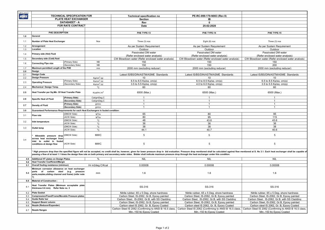
1.1 Number of Plate Heat Exchanger Nos Three (3) nos Eight (8) nos Three (3) nos
1.2 As per System Requirement As per System Requirement As per System Requirement1.3 Outdoor Outdoor Outdoor
1.4Passivated DM water
(Refer enclosed water analysis)Passivated DM water
(Refer enclosed water analysis)Passivated DM water
(Refer enclosed water analysis)1.5 CW Blowdown water (Refer enclosed water analysis) CW Blowdown water (Refer enclosed water analysis) CW Blowdown water (Refer enclosed water analysis)
(Primary Side) NB 150 150 150(Secondary Side) NB 150 150 200
1.7 mm 2000 mm (excluding reducer) 2000 mm (excluding reducer) 2000 mm (excluding reducer)2.0
2.1 Latest IS/BS/DIN/ASTM/ASME Standards Latest IS/BS/DIN/ASTM/ASME Standards Latest IS/BS/DIN/ASTM/ASME Standards 2.2 Kg/cm2 (g) 10 10 10
(Primary Side) Kg/cm2 (g) 6.5 to 8.5 Kg/sq. cm(g) 6.5 to 8.5 Kg/sq. cm(g) 6.5 to 8.5 Kg/sq. cm(g)(Secondary Side) Kg/cm2 (g) 3.5 to 5.5 Kg/sq. cm(g) 4.0 to 6.0 Kg/sq. cm(g) 3.5 to 5.5 Kg/sq. cm(g)
2.4 oC 60 60 60
2.5 Kcal/Hr./m2 6500 (Max.) 6500 (Max.) 6500 (Max.)
(Primary Side) Cal/gmDeg.C 1 1 1(Secondary Side) Cal/gmDeg.C 1 1 1(Primary Side) gm/cc 1 1 1(Secondary Side) gm/cc 1 1 1
3.0 Guaranteed Performance Requirements for each Heat Exchangers in fouled condition:
(DMCW Side) M3/hr 65 80 95(ACW Side) M3/hr 80 95 115(DMCW Side) oC 48 43.6 43.6(ACW Side) oC 36 36 36(DMCW Side) oC 38 38 38(ACW Side) oC 44.1 40.7 40.6
(DMCW Side) MWC 5 5 5
(ACW Side) MWC 5 5 5
4.0 Additional HT plates on Design Plates % NIL NIL NIL5.0
5.1 Hr m2deg C/Kcal 0.00008 0.00008 0.00008
5.2 mm 1.6 1.6 1.6
6.0 Material of Construction :
6.1 SS-316 SS-316 SS-316
6.2 Nitrile rubber, 65 ± 5 Deg. shore hardness Nitrile rubber, 65 ± 5 Deg. shore hardness Nitrile rubber, 65 ± 5 Deg. shore hardness6.3 Compression/Fixed/Frame/Movable Pressure plates Carbon Steel, IS-2062, Gr.B, Epoxy painted Carbon Steel, IS-2062, Gr.B, Epoxy painted Carbon Steel, IS-2062, Gr.B, Epoxy painted6.4 Carbon Steel, IS-2062, Gr.B, with SS Cladding Carbon Steel, IS-2062, Gr.B, with SS Cladding Carbon Steel, IS-2062, Gr.B, with SS Cladding6.5 Carbon Steel, IS-2062, Gr.B, Epoxy painted Carbon Steel, IS-2062, Gr.B, Epoxy painted Carbon Steel, IS-2062, Gr.B, Epoxy painted6.6 Carbon steel IS 2062, Gr. B, Epoxy Coated Carbon steel IS 2062, Gr. B, Epoxy Coated Carbon steel IS 2062, Gr. B, Epoxy Coated
6.7Carbon Steel IS 2062 (Confirming to ANSI B 16.5 class,
Min.-150 lb) Epoxy CoatedCarbon Steel IS 2062 (Confirming to ANSI B 16.5 class,
Min.-150 lb) Epoxy CoatedCarbon Steel IS 2062 (Confirming to ANSI B 16.5 class,
Min.-150 lb) Epoxy Coated
Nozzle (Reducer/Expander)
Nozzle flanges
Overall fouling resistance (minimun)
Minimum corrosion allowance on heat exchangerparts of carbon steel (e.g. pressureparts,nozzles,sliding channel and frame) (refer note1)
Heat Transfer Plates (Minimum acceptable platethickness 0.6 mm). Refer Note no. 3
Plate Gasket
Guide Rails/ bar
Support Beam/ column
3.3 Outlet temp
3.4
* Allowable pressure dropacross heat exchanger frominlet to outlet in fouledconditions at design flow
* High pressure drop than the specified figure will not be accepted, no credit shall be, however, given for lower pressure drop in bid evaluation. Pressure drop mentioned shall be calculated against flow mentioned at S. No 3.1. Each heat exchanger shall be capable ofpassing a flow of at least 1.1 times the design flow rate on both primary and secondary water sides. Bidder shall indicate maximum pressure drop through the heat exchanger under this condition.
Heat Transfer Coefficient/Margin
2.7 Density of Fluid
3.1 Flow rate
3.2 Inlet temperature
2.3 Operating Pressure
Mechanical Design Temp.
Heat Transfer per Sq.Mtr. Of Heat Transfer Plate
2.6 Specific Heat of Fluid
1.6 Connecting Pipe size
Maximum permitted Length of the PHE
Design
Design Code
Design Pressure
PHE DESCRIPTION
General
Arrangement
Location
Primary side (Hot) Fluid
Secondary side (Cold) fluid
TECHNICAL SPECIFICATION FORPLATE HEAT EXCHANGER
DATASHEET - A FOR RATE CONTRACT
Page 1 of 2

Technical specification no PE-RC-999-179-N003 (Rev 0)Section IB
Rev 0Date 25-02-2020
PHE TYPE-13 PHE TYPE-14 PHE TYPE-15PHE DESCRIPTION
TECHNICAL SPECIFICATION FORPLATE HEAT EXCHANGER
DATASHEET - A FOR RATE CONTRACT
6.8Carbon Steel as per IS 2062 Gr. B (Confirming to ANSI
B 16.5 class, Min.-150 lb) Epoxy CoatedCarbon Steel as per IS 2062 Gr. B (Confirming to ANSI
B 16.5 class, Min.-150 lb) Epoxy CoatedCarbon Steel as per IS 2062 Gr. B (Confirming to ANSI
B 16.5 class, Min.-150 lb) Epoxy Coated6.9 IS-1367 Gr.8.8 or equivalent IS-1367 Gr.8.8 or equivalent IS-1367 Gr.8.8 or equivalent6.10 SA 193 B7/ SA 194 2H SA 193 B7/ SA 194 2H SA 193 B7/ SA 194 2H6.11 3mm wire inserted Red Rubber 3mm wire inserted Red Rubber 3mm wire inserted Red Rubber6.12 AISI 316 18'-8' SS (3 mm thick) AISI 316 18'-8' SS (3 mm thick) AISI 316 18'-8' SS (3 mm thick)6.13 SS-316 SS-316 SS-3166.14
External Surface
a.) Surface Preparation
b.) Primer
c.) Final Paint
7.0 % 25 25 25
8.0 Unit of Measurement
8.11 Lot = 1% of plates ineach PHE
60 LOTS 160 LOTS 60 LOTS
8.21 Lot = 1% of gaskets ofeach type in each PHE
90 LOTS 240 LOTS 90 LOTS
8.3 NOS. 1 NO. 1 NO. 1 NO.
8.41 Lot = 1% of tie-rod ofeach type in each PHE
30 LOTS 80 LOTS 30 LOTS
8.51 Lot = 1% of Nuts & boltsof each type & size ineach PHE
30 LOTS 80 LOTS 30 LOTS
9.09.1 Kg/cm2 (g) 1.5 times the design pressure 1.5 times the design pressure 1.5 times the design pressure 9.2 Minutes 30 30 30
10.0
10.1
10.2
10.3
10.4
10.5
10.6
11.0
11.1
11.2
11.4
11.5
11.6
11.7
11.8
Each Plate shall be numbered in sequence with the number marked by indelible ink on each plate to permit easy reassembly. Flanges shall be as per ANSI 16.5 or equivalent. Thickness of pressure and frame plates shall be as per ASME Sect. VIII div.1. Painting as specified at Sl. No. 6.14 above shall be subject to customer/BHEL approval during detailed engineering.
Minimum Corrosion allowance on thickness (as per ASME Sec. VIII Div. I)Metallurgy specified above is bare minimum . Equivalent or Superior materials suitable for fluid handled is also acceptable subject to Customer/BHEL approval.
11.3Plate thickness should be adequate to withstand all operating conditions but with Minimum plate thickness of 0.6 mm (No negative tolerance allowed in thickness specified). The plates shall be pressed from one single piece with the corrugationbeing smooth, uniform and identical for every plate. The plate Heat exchangers shall be single pass type. Heat transfer plates shall be sealed at their outer edges and around the ports by gaskets in order to prevent leakage and inter-mixing of fluids.Double sealing arrangement shall be provided at outer edge and around ports with the inter space between the seals vented to atmosphere in order to avoid inter-mixing of liquids in case of gaskets failure.
Primary side water flow (80% to 115%) vs. Pressure drop and outlet temperature (Secondary side flow – 100%)
Secondary side water flow (80% to 115%) vs. Secondary side pressure drop and primary side outlet temp (Primary side flow – 100%)
Primary side water outlet temperature vs. Primary side inlet temp.
Film heat transfer coefficient curve
Correction Curves.
Minimum Standard requirement of the PHE to be offered by the bidder.
Fasteners (Nuts & bolts etc.)
Hydrotesting at Shop Hydrotesting PressureDuration of Hydrotesting
Performance curves and figures to be furnished during contact stage
Primary side water outlet temperature vs. Secondary side water inlet temperature.
Extra Carrying capacity to be provided on frame assembly.Spares
Heat Transfer Plates
Gaskets (All types)
Valves
Tie Rods
Name Plate
Wetted fasteners
Painting
All surface other than stainless steels shall be painted.
The steel surface to be applied with painting shall be thoroughlycleaned before applying painting by shotblasting (SA 2.5) etc shallbe subjected to BHEL/Customer approval.
For all the steel surfaces, a coat of chlorinated rubber based zincphosphate primer of minimum thickness DFT of 50 micronsfollowed up with undercoat of chlorinated rubber paint of minimumDFT of 50 microns shall be applied. Then, intermediate coatconsisting of one coat of chlorinated rubber based paint pigmentedwith Titanium di-oxide with minimum DFT of 50 microns andtopcoat consisting of two coats of chlorinated rubber paint ofapproved shade and color with glossy finish and DFT of 100microns shall be provided. Total DFT of paint system shall not beless than 200 microns.
All surface other than stainless steels shall be painted.
The steel surface to be applied with painting shall be thoroughlycleaned before applying painting by shotblasting (SA 2.5) etc shallbe subjected to BHEL/Customer approval.
For all the steel surfaces, a coat of chlorinated rubber based zincphosphate primer of minimum thickness DFT of 50 micronsfollowed up with undercoat of chlorinated rubber paint of minimumDFT of 50 microns shall be applied. Then, intermediate coatconsisting of one coat of chlorinated rubber based paint pigmentedwith Titanium di-oxide with minimum DFT of 50 microns andtopcoat consisting of two coats of chlorinated rubber paint ofapproved shade and color with glossy finish and DFT of 100microns shall be provided. Total DFT of paint system shall not beless than 200 microns.
All surface other than stainless steels shall be painted.
The steel surface to be applied with painting shall be thoroughlycleaned before applying painting by shotblasting (SA 2.5) etc shallbe subjected to BHEL/Customer approval.
For all the steel surfaces, a coat of chlorinated rubber based zincphosphate primer of minimum thickness DFT of 50 micronsfollowed up with undercoat of chlorinated rubber paint of minimumDFT of 50 microns shall be applied. Then, intermediate coatconsisting of one coat of chlorinated rubber based paint pigmentedwith Titanium di-oxide with minimum DFT of 50 microns andtopcoat consisting of two coats of chlorinated rubber paint ofapproved shade and color with glossy finish and DFT of 100microns shall be provided. Total DFT of paint system shall not beless than 200 microns.
Flange/ Counter flanges
Tightening Bolts/Rods & Nuts
Nozzle flange bolts / nuts
Nozzle flange gasket
Page 2 of 2
Technical specification no PE-RC-999-179-N003 (Rev 0)Section IB
Rev 0Date 25-02-2020
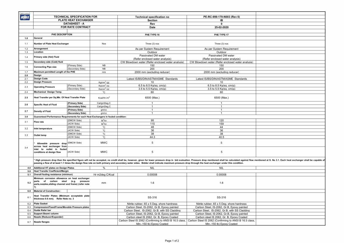
PHE TYPE-16 PHE TYPE-17
1.0
1.1 Number of Plate Heat Exchanger Nos Three (3) nos Three (3) nos
1.2 As per System Requirement As per System Requirement1.3 Outdoor Outdoor
1.4Passivated DM water
(Refer enclosed water analysis)Passivated DM water
(Refer enclosed water analysis)1.5 CW Blowdown water (Refer enclosed water analysis) CW Blowdown water (Refer enclosed water analysis)
(Primary Side) NB 150 150(Secondary Side) NB 200 200
1.7 mm 2000 mm (excluding reducer) 2000 mm (excluding reducer)2.0
2.1 Latest IS/BS/DIN/ASTM/ASME Standards Latest IS/BS/DIN/ASTM/ASME Standards 2.2 Kg/cm2 (g) 10 10
(Primary Side) Kg/cm2 (g) 6.5 to 8.5 Kg/sq. cm(g) 6.5 to 8.5 Kg/sq. cm(g)(Secondary Side) Kg/cm2 (g) 3.5 to 5.5 Kg/sq. cm(g) 3.5 to 5.5 Kg/sq. cm(g)
2.4 oC 60 60
2.5 Kcal/Hr./m2 6500 (Max.) 6500 (Max.)
(Primary Side) Cal/gmDeg.C 1 1(Secondary Side) Cal/gmDeg.C 1 1(Primary Side) gm/cc 1 1(Secondary Side) gm/cc 1 1
3.0 Guaranteed Performance Requirements for each Heat Exchangers in fouled condition:
(DMCW Side) M3/hr 95 120(ACW Side) M3/hr 115 159(DMCW Side) oC 48 44(ACW Side) oC 36 36(DMCW Side) oC 38 38(ACW Side) oC 44.3 40.5
(DMCW Side) MWC 5 5
(ACW Side) MWC 5 5
4.0 Additional HT plates on Design Plates % NIL NIL5.0
5.1 Hr m2deg C/Kcal 0.00008 0.00008
5.2 mm 1.6 1.6
6.0 Material of Construction :
6.1 SS-316 SS-316
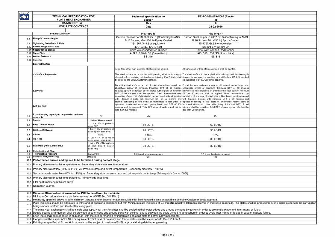
6.2 Nitrile rubber, 65 ± 5 Deg. shore hardness Nitrile rubber, 65 ± 5 Deg. shore hardness6.3 Compression/Fixed/Frame/Movable Pressure plates Carbon Steel, IS-2062, Gr.B, Epoxy painted Carbon Steel, IS-2062, Gr.B, Epoxy painted6.4 Carbon Steel, IS-2062, Gr.B, with SS Cladding Carbon Steel, IS-2062, Gr.B, with SS Cladding6.5 Carbon Steel, IS-2062, Gr.B, Epoxy painted Carbon Steel, IS-2062, Gr.B, Epoxy painted6.6 Carbon steel IS 2062, Gr. B, Epoxy Coated Carbon steel IS 2062, Gr. B, Epoxy Coated
6.7Carbon Steel IS 2062 (Confirming to ANSI B 16.5 class,
Min.-150 lb) Epoxy CoatedCarbon Steel IS 2062 (Confirming to ANSI B 16.5 class,
Min.-150 lb) Epoxy Coated
Nozzle (Reducer/Expander)
Nozzle flanges
Overall fouling resistance (minimun)
Minimum corrosion allowance on heat exchangerparts of carbon steel (e.g. pressureparts,nozzles,sliding channel and frame) (refer note1)
Heat Transfer Plates (Minimum acceptable platethickness 0.6 mm). Refer Note no. 3
Plate Gasket
Guide Rails/ bar
Support Beam/ column
3.3 Outlet temp
3.4
* Allowable pressure dropacross heat exchanger frominlet to outlet in fouledconditions at design flow
* High pressure drop than the specified figure will not be accepted, no credit shall be, however, given for lower pressure drop in bid evaluation. Pressure drop mentioned shall be calculated against flow mentioned at S. No 3.1. Each heat exchanger shall be capable ofpassing a flow of at least 1.1 times the design flow rate on both primary and secondary water sides. Bidder shall indicate maximum pressure drop through the heat exchanger under this condition.
Heat Transfer Coefficient/Margin
2.7 Density of Fluid
3.1 Flow rate
3.2 Inlet temperature
2.3 Operating Pressure
Mechanical Design Temp.
Heat Transfer per Sq.Mtr. Of Heat Transfer Plate
2.6 Specific Heat of Fluid
1.6 Connecting Pipe size
Maximum permitted Length of the PHE
Design
Design Code
Design Pressure
PHE DESCRIPTION
General
Arrangement
Location
Primary side (Hot) Fluid
Secondary side (Cold) fluid
TECHNICAL SPECIFICATION FORPLATE HEAT EXCHANGER
DATASHEET - A FOR RATE CONTRACT
Page 1 of 2
Technical specification no PE-RC-999-179-N003 (Rev 0)Section IB
Rev 0Date 25-02-2020
PHE TYPE-16 PHE TYPE-17PHE DESCRIPTION
TECHNICAL SPECIFICATION FORPLATE HEAT EXCHANGER
DATASHEET - A FOR RATE CONTRACT
6.8Carbon Steel as per IS 2062 Gr. B (Confirming to ANSI
B 16.5 class, Min.-150 lb) Epoxy CoatedCarbon Steel as per IS 2062 Gr. B (Confirming to ANSI
B 16.5 class, Min.-150 lb) Epoxy Coated6.9 IS-1367 Gr.8.8 or equivalent IS-1367 Gr.8.8 or equivalent6.10 SA 193 B7/ SA 194 2H SA 193 B7/ SA 194 2H6.11 3mm wire inserted Red Rubber 3mm wire inserted Red Rubber6.12 AISI 316 18'-8' SS (3 mm thick) AISI 316 18'-8' SS (3 mm thick)6.13 SS-316 SS-3166.14
External Surface
a.) Surface Preparation
b.) Primer
c.) Final Paint
7.0 % 25 25
8.0 Unit of Measurement
8.11 Lot = 1% of plates ineach PHE
60 LOTS 60 LOTS
8.21 Lot = 1% of gaskets ofeach type in each PHE
90 LOTS 90 LOTS
8.3 NOS. 1 NO. 1 NO.
8.41 Lot = 1% of tie-rod ofeach type in each PHE
30 LOTS 30 LOTS
8.51 Lot = 1% of Nuts & boltsof each type & size ineach PHE
30 LOTS 30 LOTS
9.09.1 Kg/cm2 (g) 1.5 times the design pressure 1.5 times the design pressure 9.2 Minutes 30 30
10.0
10.1
10.2
10.3
10.4
10.5
10.6
11.0
11.1
11.2
11.4
11.5
11.6
11.7
11.8
Each Plate shall be numbered in sequence with the number marked by indelible ink on each plate to permit easy reassembly. Flanges shall be as per ANSI 16.5 or equivalent. Thickness of pressure and frame plates shall be as per ASME Sect. VIII div.1. Painting as specified at Sl. No. 6.14 above shall be subject to customer/BHEL approval during detailed engineering.
Minimum Corrosion allowance on thickness (as per ASME Sec. VIII Div. I)Metallurgy specified above is bare minimum . Equivalent or Superior materials suitable for fluid handled is also acceptable subject to Customer/BHEL approval.
11.3Plate thickness should be adequate to withstand all operating conditions but with Minimum plate thickness of 0.6 mm (No negative tolerance allowed in thickness specified). The plates shall be pressed from one single piece with the corrugationbeing smooth, uniform and identical for every plate. The plate Heat exchangers shall be single pass type. Heat transfer plates shall be sealed at their outer edges and around the ports by gaskets in order to prevent leakage and inter-mixing of fluids.Double sealing arrangement shall be provided at outer edge and around ports with the inter space between the seals vented to atmosphere in order to avoid inter-mixing of liquids in case of gaskets failure.
Primary side water flow (80% to 115%) vs. Pressure drop and outlet temperature (Secondary side flow – 100%)
Secondary side water flow (80% to 115%) vs. Secondary side pressure drop and primary side outlet temp (Primary side flow – 100%)
Primary side water outlet temperature vs. Primary side inlet temp.
Film heat transfer coefficient curve
Correction Curves.
Minimum Standard requirement of the PHE to be offered by the bidder.
Fasteners (Nuts & bolts etc.)
Hydrotesting at Shop Hydrotesting PressureDuration of Hydrotesting
Performance curves and figures to be furnished during contact stage
Primary side water outlet temperature vs. Secondary side water inlet temperature.
Extra Carrying capacity to be provided on frame assembly.Spares
Heat Transfer Plates
Gaskets (All types)
Valves
Tie Rods
Name Plate
Wetted fasteners
Painting
All surface other than stainless steels shall be painted.
The steel surface to be applied with painting shall be thoroughlycleaned before applying painting by shotblasting (SA 2.5) etc shallbe subjected to BHEL/Customer approval.
For all the steel surfaces, a coat of chlorinated rubber based zincphosphate primer of minimum thickness DFT of 50 micronsfollowed up with undercoat of chlorinated rubber paint of minimumDFT of 50 microns shall be applied. Then, intermediate coatconsisting of one coat of chlorinated rubber based paint pigmentedwith Titanium di-oxide with minimum DFT of 50 microns andtopcoat consisting of two coats of chlorinated rubber paint ofapproved shade and color with glossy finish and DFT of 100microns shall be provided. Total DFT of paint system shall not beless than 200 microns.
All surface other than stainless steels shall be painted.
The steel surface to be applied with painting shall be thoroughlycleaned before applying painting by shotblasting (SA 2.5) etc shallbe subjected to BHEL/Customer approval.
For all the steel surfaces, a coat of chlorinated rubber based zincphosphate primer of minimum thickness DFT of 50 micronsfollowed up with undercoat of chlorinated rubber paint of minimumDFT of 50 microns shall be applied. Then, intermediate coatconsisting of one coat of chlorinated rubber based paint pigmentedwith Titanium di-oxide with minimum DFT of 50 microns andtopcoat consisting of two coats of chlorinated rubber paint ofapproved shade and color with glossy finish and DFT of 100microns shall be provided. Total DFT of paint system shall not beless than 200 microns.
Flange/ Counter flanges
Tightening Bolts/Rods & Nuts
Nozzle flange bolts / nuts
Nozzle flange gasket
Page 2 of 2

ANNEXURE- VI
CLARIFIED WATER ANALYSIS---------------------------------------------------------------------------------------------------------------------------Sl. Constituent as mg/ litre mg/LitreNo. St-I St-II--------------------------------------------------------------------------------------------------------------------------
A) COOLING WATER ANALYSIS /CW BLOW DOWN WATER ANALYSIS
1. Calcium CaCO3 237 316
2. Magnesium CaCO3 219 292
3. Sodium CaCO3 195 260
4. Potassium CaCO3 18 24
5. Total Cations CaCO3 669 892
6. M-Alkalnaity CaCO3 120 120
7. P-Alkalinity CaCO3 0 0
8. Nitrate CaCO3 CaCO3 6.6 8.8
9. Chloride CaCO3 189 252
10. Sulphate CaCO3 120 160
11. Total Anions CaCO3 669 892
12. Silica SiO2
45 60
13. Iron Fe 0.36 0.48
14. pH Value - 6.5-6.9 6.5-6.9
15. Turbidity NTU 4.5 6
16. Total Dissolved solids CaCO3 735 980
17. Organic matter(Oxygen absorbed from Acid Permanganate In 4 Hrs.) mg/l 0.1 0.1
Note : The C.W system is expected to operate at about 3 Cycles of Concentration for St- Iand 4 cycles of concentration for St-II.
In some cases calcium may go up to 721 mg/litre.
TITLE : SPECIFICATION NO. PE-RC-999-179-N003 TECHNICAL SPECIFICATION FOR
RATE CONTRACT OF PLATE HEAT EXCHANGERS SECTION II
REV. NO. 0 DATE 22/02/2020
SECTION II
IIA STANDARD TECHNICAL SPECIFICATION
STANDARD QUALITY PLAN
TITLE : SPECIFICATION NO. PE-TS-999-179-N001
STANDARD TECHNICAL SPECIFICATION VOLUME :
FOR SECTION : IIA
PLATE HEAT EXCHANGER REV. NO. 01 DATE : 2/5/2018
SHEET 1 OF 1
SECTION - IIA
PLATE HEAT EXCHANGER
STANDARD TECHNICAL SPECIFICATION
DATA SHEET C
TITLE : SPECIFICATION NO. PE-TS-999-179-N001
STANDARD TECHNICAL SPECIFICATION VOLUME :
FOR SECTION : IIA
PLATE HEAT EXCHANGER REV. NO. 01 DATE : 2/5/18
SHEET 1 OF 11
1.00.00 GENERAL
This specification covers the Design, Performance requirements, Constructional
Features, Materials requirements, manufacture, assembly, Inspection and
Testing at Manufacturer’s and/ or his sub-contractor’s works and Painting
requirements for delivery of Plate Heat Exchanger complete with all accessories
as specified herein-after.
1.01.00 SYSTEM DESCRIPTION:
1.01.01 The Plate Heat Exchanger are intended to be used in closed circuit DM cooling
water circuit for Cooling Hot passivated DM Water by Auxiliary Cooling Water
(Clarified / Sea Water).
1.01.02 Passivated DM Water is circulated through various auxiliary coolers of
TG/SG/Station Aux., in closed loop by means of pumps. This DM water picks up
heat from different cooling equipment’s. Heat from DM water is transferred to
auxiliary cooling water (Secondary side) thru’ the Plate Heat Exchangers
covered under this specification.
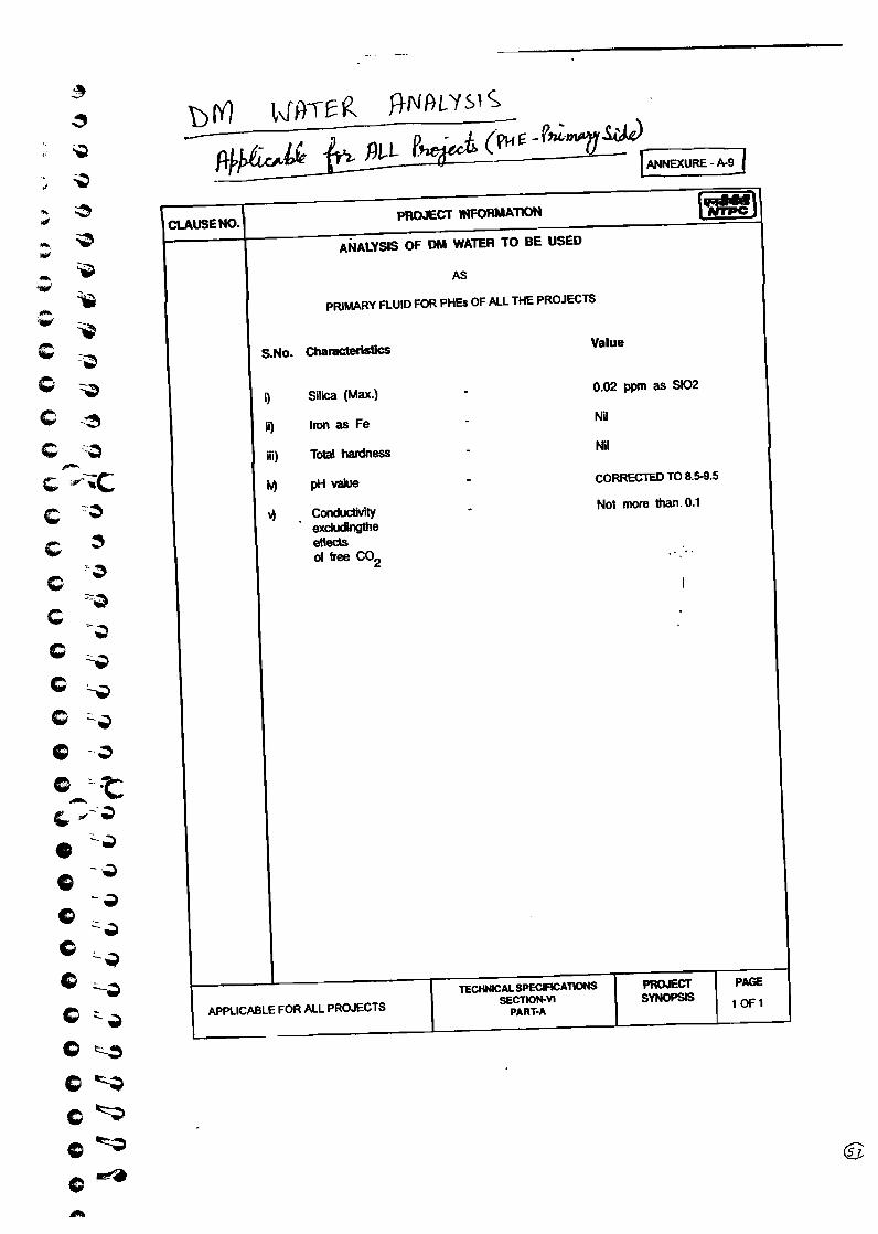
1.01.03 The analysis of DM Water, Clarified /Sea Water (Auxiliary cooling water) to be
handled by the Plate Heat Exchangers are attached as Annexure to Data
Sheet-A.
1.01.04 A strainer of 2 mm size at ACW inlet lines of PHE is provided and backwashing of
PHE’s is not envisaged.
2.00.00 CODES AND STANDARDS :
2.01.00 The design manufacture and testing of the plate heat exchanger complete with
all accessories, shall generally conform to the latest editions of the following
appropriate standards.
2.01.01 IS/BS/DIN/US Standards regarding pressure vessels, pressure piping, pipes,
valves, flanges and other as necessary.
2.01.02 IS/ BS/ DIN/ ASTM for material specification and testing procedures.
2.02.00 In case of any conflict between the above codes/ standards and this
TITLE : SPECIFICATION NO. PE-TS-999-179-N001
STANDARD TECHNICAL SPECIFICATION VOLUME :
FOR SECTION : IIA
PLATE HEAT EXCHANGER REV. NO. 01 DATE : 2/5/18
SHEET 2 OF 11
specification, the latter shall prevail and in case of any further conflict in the
matter, the interpretation of the specification by the Engineer shall be final and
binding.
3.00.00 SCOPE OF SUPPLY:
3.01.00 The details of the Plate Heat Exchangers with the quantity, design parameters
etc. to be supplied shall be as per Data Sheet-A enclosed at Section IB.
3.02.00 Each Plate Heat Exchanger (quantity and other details specified in Data
Sheet-A) shall be complete with the following accessories and auxiliaries.
(i) Suitable drain and vent connections for both primary (DMCW) and Secondary
Water (Raw Water/ Sea Water as applicable) streams complete with isolation
valves.
(ii) Supporting arrangement complete with foundation plate channels, anchor bolts,
nuts, sleeves, inserts etc.
(iii) Lifting arrangement i.e., lifting lugs, eye bolts etc.
(iv) Matching counter flanges with necessary bolts, nuts, and gaskets for all flanged
terminal points, including for DMCW and ACW inlet/outlet nozzles & reducers/
expanders.
(v) Inspection ports at the End plates of the PHE.
(vi) Other accessories as required to make PHE’s complete in all respects.
(vii) Commissioning spares, if any.
(viii) One Ratchet spanner for each type of PHE is included in bidder’s scope of
supply.
(ix) Matching piece (Reducer/Expander), with coatings (as required), to match the
PHE nozzle connection with connecting pipe size at DMCW side/ ACW side as
indicated in Data Sheet. In case of sea Water, Matching piece on ACW Side
(Secondary) shall be flanged with coatings (as required for sea water
application).
(x) Spares as applicable as per data sheet A at Section IB.
3.03.00 Finish paints for touch up painting of equipment after erection at Site in sealed
containers.
3.04.00 Items though not specifically mentioned in the specification but needed to
complete the equipment to meet the intent of specification, shall also be deemed
to be included unless otherwise specifically mentioned in exclusions.
TITLE : SPECIFICATION NO. PE-TS-999-179-N001
STANDARD TECHNICAL SPECIFICATION VOLUME :
FOR SECTION : IIA
PLATE HEAT EXCHANGER REV. NO. 01 DATE : 2/5/18
SHEET 3 OF 11
4.00.00 EXCLUSIONS :
The following are excluded from the bidder’s scope:
4.01.00 Civil foundation works required for installation of the heat exchangers.
4.02.00 Piping, valves etc., on the external circuit of both primary and secondary water
streams.
4.03.00 Erection & Commissioning of equipment at site.
5.00.00 DESIGN AND CONSTRUCTION:
5.01.00 General Requirements:
5.01.01 Unless otherwise necessary manufacturer’s standard and proven models of the
plate heat exchanger shall be supplied.
5.01.02 The equipment shall be capable of safe, proper and continuous operation at all
heat loads and water from up to those corresponding to the operating conditions
mentioned in Data Sheet-A. Vibration, noise, mechanical and thermal stresses
shall be kept within allowable limits specified by relevant codes/ standards in
design. Due attention shall be given to ease of maintenance, repair and cleaning.
5.01.03 Suitable corrosion allowance shall be provided wherever necessary. The
corrosion allowance for the heat exchanger parts such as pressure plates
(support plates), nozzles, sliding channels and frame shall be 1.6 mm
(minimum).
5.01.04 Each heat exchanger shall be capable of passing a flow of at least 1.1. times the
design flow rate on both primary and secondary water sides. Bidder shall indicate
maximum pressure drop through the heat exchanger under this condition.
5.01.05 For the purpose of calculating dirty overall heat transfer coefficient a total fouling
factor as given in Data Sheet-A shall be assumed. It is expected that the cleaning
frequency shall be once in a year with the above fouling factor.
5.01.06 No back wash for the heat exchangers is envisaged.
5.02.00 Performance Requirements:
5.02.01 The pressure drop across plate heat exchanger from inlet to outlet in fouled
conditions for primary and secondary sides, shall not be more than those
TITLE : SPECIFICATION NO. PE-TS-999-179-N001
STANDARD TECHNICAL SPECIFICATION VOLUME :
FOR SECTION : IIA
PLATE HEAT EXCHANGER REV. NO. 01 DATE : 2/5/18
SHEET 4 OF 11
specified in Data Sheet-A, for the specified flow rates.
5.02.02 For the specified flow rate and inlet temperature, the primary side (hot fluid) outlet
temperature shall not be more than that specified in Data Sheet-A.
5.02.03 In the event of failure to meet the above stipulated performance requirements,
the equipment will be outrightly rejected.
5.03.00 Construction of Heat Exchanger:
5.03.01 Heat transfer plates shall be packed in a frame consisting of fixed frame plate
and movable pressure plate and aligned at top and bottom on carrying bars.
Design shall be such that cleaning is possible without dismantling the piping.
5.03.02 Heat transfer plates shall be sealed at their outer edges and around the ports by
gaskets in order to prevent leakage and inter-mixing of fluids.
Double sealing arrangement shall be provided at outer edge and around ports.
The interspace between the seals shall be vented to atmosphere in order to
avoid inter-mixing of liquids in case of gaskets failure.
The gasket arrangement shall be such that it receives continuous support to
ensure a long gasket life. The gasket should be able to retain their properties and
shape over a life period of 10 years.
5.03.03 Heat transfer plates shall be provided with sufficient thickness in order to impart
sufficient rigidity to the plates particularly from handling considerations. Plates
shall have contact points in order to provide inter-plate supports. The recesses
on the plates are suitably strengthened by a reinforcement plate.
Plate thickness shall be adequate to withstand all operating conditions as
specified in Datasheet-A. Flanges shall be as per ANSI B 16.5 or equivalent.
Thickness of pressure and frame plates shall be as per ASME Sec. VIII Div. 1.
25% extra capacity for additional plates shall be provided in frame.
Each plate shall be numbered in sequence. The number shall be marked by
indelible ink on the plate to permit easy reassembly. The plates shall be pressed
from one piece. They shall be pressed in single / progressive manner.
The corrugation shall be smooth, uniform and identical for every plate. The PHE

TITLE : SPECIFICATION NO. PE-TS-999-179-N001
STANDARD TECHNICAL SPECIFICATION VOLUME :
FOR SECTION : IIA
PLATE HEAT EXCHANGER REV. NO. 01 DATE : 2/5/18
SHEET 5 OF 11
bottom frame plate and support should have fixing lugs and cleats to keep
provision for enabling to fit trough with outlet nozzle fitted underneath to collect
and drain out water in the event of leakages.
5.03.04 Frame for each heat exchanger shall have extra capacity to accommodate the
additional plates if required in future because of any reason whatsoever. The
extra capacity to be provided is indicated in Data Sheet-A.
The upper carrying bar and lower guide bar shall be rigid in construction without
any risk or sagging or buckling, and shall facilitate easy guiding of the plates.
5.03.05 All inlet, outlet and other nozzles shall be flanged type and shall be as specified in
Data Sheet-A. Counter flanges complete with gaskets, bolts, nuts and coatings
(wherever necessary) shall be supplied for all the nozzle connections. The
nozzle sizes of primary / secondary streams of PHEs shall be of adequate size
within acceptable range of velocity. The size selection shall be subject to
approval in the event of order.
5.03.06 If necessary, relief valves shall be provided on both the streams.
5.04.00 Materials of construction :
Material of the heat transfer plates and gaskets shall be consistent with the fluid
handled. However, material specification for various parts shall be equal or
superior to those specified in Data Sheet - A.
5.05.00 Foundation And Lifting Arrangements:
5.05.01 Plate heat exchanger shall be supplied with necessary foundation plates, anchor
bolts, sleeves, nuts, inserts etc.
5.05.02 Plate heat exchanger shall be equipped with suitable lifting lugs/ eye-bolts to
facilitate handling during erection and maintenance.
6.00.00 PAINTING:
6.01.00 The surface preparation of all exterior and interior surfaces of plate heat
exchanger shall include the following:
a) Removal of oil, grease, dirt and swarf etc.,
TITLE : SPECIFICATION NO. PE-TS-999-179-N001
STANDARD TECHNICAL SPECIFICATION VOLUME :
FOR SECTION : IIA
PLATE HEAT EXCHANGER REV. NO. 01 DATE : 2/5/18
SHEET 6 OF 11
b) Removal of rust and scale etc.,
c) Sand blasting/ shot blasing.
6.02.00 All exterior surfaces of PHEs shall be sand / shot blasted, painted with primer and
finish coated with coal tar based epoxy coating of min. 250 microns thickness.
Colour shade etc. shall be subject to BHEL / customer approval.
7.00.00 SHOP INSPECTION AND TESTS:
7.01.00 General:
7.01.01 Manufacturer shall conduct all tests and stage inspections as per the approved
quality plan to ensure that the plate heat exchanger shall conform to the
requirements of this specification and of the applicable codes/ standards.
7.01.02 All materails used for manufacture/ fabrication of the plate heat exchanger
components shall be of tested quality. Relevant test certificates for chemical
analysis, mechanical tests and heat treatment shall be made available before the
final shop inspection. In case the relevant test certificates are not available, the
manufacturer shall arrange to carry out the necessary tests required as per
approved quality plan and applicable codes at his cost, for which samples shall
be identified by BHEL’s representative.
7.01.03 All shop tests shall be conducted in the presence of BHEL’s representative and
test certificates for the same shall be furnished to BHEL for approval.
7.01.04 Qualification of welding procedures and welders shall be as per ASME B&PV
Code, Section-IX/applicable code.
7.02.00 Heat Transfer Plates:
7.02.01 Plate material used for pressing shall be furnished with mill test report showing
chemical and physical properties and heat treatment records. Suitable
correlating mark shall be available, so that BHEL’s inspector can identify the
material with test certificates before pressing the plates.
7.02.02 After pressing visual and dimensional checks on the plates shall be made in the
presence of BHEL’s inspector, on sampling basis.
TITLE : SPECIFICATION NO. PE-TS-999-179-N001
STANDARD TECHNICAL SPECIFICATION VOLUME :
FOR SECTION : IIA
PLATE HEAT EXCHANGER REV. NO. 01 DATE : 2/5/18
SHEET 7 OF 11
7.02.03 The heat transfer plates from each lot of the plates shall be tested by liquid / dye
penetrant test in order to check for cracks and other surface defects in presence
of BHEL / customer’s representative / third party (Llyods, TUV or equivalent). If
any defect is detected in any of these plates, the whole lot shall be tested and
plates without defects only shall be accepted. Plates cleaning agent, liquid
penetrant and developer shall not contain any halogen. Procedure for DP test
shall be subjected to purchaser’s approval. Quantum of check shall be subject to
customer’s/purchaser’s approval in the event of order.
7.02.04 The heat transfer plates shall be tested by light box test in order to check for
cracks and other surface defects in presence of BHEL / customer’s
representative / third party (Llyods, TUV or equivalent). The plates without
defects only shall be accepted. Procedure for Light box test shall be subjected to
purchaser’s approval. Quantum of check shall be subject to
customer’s/purchaser’s approval in the event of order.
7.02.05 Inspection Requirements
(i) Inspection for “Pressing of plates to form whole corrugation of the heat transfer
plate” shall be from third party like TUV/Lloyd and certificate shall be submitted
for review of BHEL.
(ii) Minimum requirement for quality Plan shall be as per quality plan attached in the
Section IIA of the specification. Manufacturing Quality Plan for PHE shall be
subject to approval during detail engineering. No price implication shall be
admissible to QP approval by BHEL/Customer.
(iii) Heat transfer area for the PHE shall be measured by White light scanning /
similar method during contract stage to ascertain the correctness of heat transfer
area.
Bidder to note that Heat Transfer Area measured by White Light Scanning should
not have negative tolerance more than 3% w.r.t to the heat transfer area
indicated by bidder. However in the case of negative tolerance (limited to
maximum 3 percent) , bidder has to provide additional plates proportionately, as
free issue, assembled into all the applicable PHE's before the Final inspection
and "As built Certificate" shall be issued by the bidder accordingly. Bidder to note
that negative tolerance beyond three percent shall not be accepted, however no
credit shall be given to the bidder for positive tolerance of the plate area
measurement.
TITLE : SPECIFICATION NO. PE-TS-999-179-N001
STANDARD TECHNICAL SPECIFICATION VOLUME :
FOR SECTION : IIA
PLATE HEAT EXCHANGER REV. NO. 01 DATE : 2/5/18
SHEET 8 OF 11
7.03.00 Gaskets :
7.03.01 Certificate on Chemical composition of the gasket material shall be furnished to
prove the quality. Sample testing in presence of BHEL’s inspector shall also be
conducted if desired.
7.03.02 Shore hardness test shall be conducted on the gasket and certificate shall be
furnished. Sample tests shall also be done in presence of BHEL’s inspector.
7.03.03 Visual and dimensional check on a sampling basis shall be done. Plates and
gaskets assembled together, will be inspected for proper assembly.
7.04.00 Frame Assembly:
7.04.01 All materials for various components of frame assembly viz frame plate, pressure
plate, carrying bar, guide bar, tightening/ clamping bolts and nuts etc., shall be of
tested quality and test certificates for chemical composition and physical
properties shall be furnished.
7.04.02 If the thickness of the plates used for frame and pressure plates is 40 mm or
more the same shall be checked ultrasonically to demonstrate the absence of
lamination and lack of fusion etc.
7.05.00 All weld joints used for fabrication of heat exchangers shall be subjected to
suitable non-destructive examination. This shall include 100% magnetic particle
examination or other suitable NDT of all welds.
7.06.00 Nozzle and Flanged Connections:
All materails for various nozzles, flanges, gaskets, nuts, bolts etc., shall be of
tested quality and correlating test certificates for chemical and mechanical
properties shall be furnished. These shall be checked for the edge preparation, fit
up, orientation and satisfactory working with matching parts.
7.07.00 Dimensional Checks:
Dimensional checks of various components of plate heat exchanger, plate pack
length etc., shall be carried out as per assembly drawings approved by BHEL.
TITLE : SPECIFICATION NO. PE-TS-999-179-N001
STANDARD TECHNICAL SPECIFICATION VOLUME :
FOR SECTION : IIA
PLATE HEAT EXCHANGER REV. NO. 01 DATE : 2/5/18
SHEET 9 OF 11
7.08.00 Hydrostatic Test :
Plate heat exchanger shall by hydrostatically tested at a pressure of 1.5 times the
design pressure. Pressure shall be applied first to both the sides of the plate at
the same time, then only to one side and finally only to other side. Pressure shall
be maintained for a minimum period of 30 Minutes for each of the three cases
above and for such additional time as may be necessary to conduct the
examination, for leakage. The examination shall be performed on all joints,
connections and regions of high stress. Fluorescent dye shall be used during the
test for ease of leak detection. There shall be no structural damage deformation
of the plates.
8.00.00 PERFORMANCE GUARANTEE AND TESTING AT SITE:
8.01.00 Performance Guarantee
8.01.01 After completion of erection at site, performance test will be conducted to ensure
that the plate heat exchanger operation meets the specified requirements.
Rectification of all defects shall have to be done by the supplier at no extra cost to
the purchaser. However the purchaser reserves the right to reject the equipment/
parts not meeting the requirement if the deficiency still persists.
8.01.02 The Plate Heat Exchanger shall be guaranteed to meet the performance
requirements as given in Data Sheet-A of Section-IB and also for trouble free
operation after commissioning.
8.02.00 PG Testing at Site
8.02.01 The guaranteed performance figures of the plat heat exchangers shall be proved
by the supplier during the performance testing at site (as applicable). If the
results of these tests show the non-performance of the heat exchanger to meet
the guaranteed values, the supplier shall modify the heat exchanger as required
to enable it to meet the guarantees.
Even If PG test is not envisaged for any project, in the event of
performance shortfall at site or if insisted by customer, performance
parameters (Flow, Temperature rise & Pressure drop) are to be
demonstrated at site by bidder without any cost implication to BHEL.
8.02.02 All duly calibrated instruments required for PG testing including for flow
TITLE : SPECIFICATION NO. PE-TS-999-179-N001
STANDARD TECHNICAL SPECIFICATION VOLUME :
FOR SECTION : IIA
PLATE HEAT EXCHANGER REV. NO. 01 DATE : 2/5/18
SHEET 10 OF 11
measurements shall be arranged by the bidder and taken back after the Test.
The computation of flow by characteristics curve of Pumps for PG Testing of
PHE’s shall not be permitted.
8.02.03 It is clarified that pressure gauges and temperature gauges are provided at each
PHE inlet / outlet on both primary / secondary sides and bidder can install their
calibrated instruments on these locations. It is further clarified that due to layout
constraints flow measuring instruments installation on pipe is not feasible. Bidder
shall arrange the Ultra-sonic flow meter / similar type of instrument for PG testing.
8.02.04 At the time of performance testing, cleaning of the plates (if required) and
instruments like pressure gauges, temp. Gauges, flow measuring instruments
etc. shall be arranged by the bidder and no instruments shall be provided by
BHEL for performance testing.
9.00.00 QUALITY ASSURANCE & QUALITY PLAN:
9.01.00 The Plate Heat Exchanger to be supplied shall have assured quality and
workmanship.
9.02.00 Typical quality plan is enclosed in section-IIB for guidance. The bidder shall
comply with these minimum requirements and shall furnish his own quality plan
for approval. The quality plan shall be subjected to customer’s / purchaser’s
approval in the event of order without any cost implication.
10.00.00 DRAWINGS, DATA & INFORMATION TO BE SUBMITTED ALONG WITH THE
OFFER:
10.01.00 Compliance certificate (duly signed and stamped).
10.02.00 Guarantee Schedule (duly signed and stamped).
10.03.00 Thermal sizing calculations (only for reference and shall be reviewed during
detailed engineering).
10.04.00 GA Drg. of PHE indicating all-important details for Layout purpose, withdrawal
space required for plates, weight of assembly, nozzle & matching piece details
etc. (only for reference and shall be reviewed during detailed engineering).
10.05.00 Deviation Schedule (as per NIT format; in case of nil Deviation, mention “No
Deviation” in the schedule and submit).
TITLE : SPECIFICATION NO. PE-TS-999-179-N001
STANDARD TECHNICAL SPECIFICATION VOLUME :
FOR SECTION : IIA
PLATE HEAT EXCHANGER REV. NO. 01 DATE : 2/5/18
SHEET 11 OF 11
11.00.00 DRAWINGS, DATA & INFORMATION TO BE SUBMITTED AFTER THE
AWARD OF CONTRACT:
The drawings, data and other documents as required in Data Sheet-C shall be
furnished after the award of contract.
12.00.00 In the event of Contradictions between Section I and Section-II of the
Specification, the requirements of Section-I shall prevail over the Section-II.
TITLE : SPECIFICATION NO. PE-TS-999-179-N001
DATA SHEET - C VOLUME :
PLATE HEAT EXCHANGER SECTION : IIA
REV. NO. 01 DATE : 2/5/18
SHEET 1 OF 1
1.00.00 DRAWINGS, DATA AND INFORMATION TO BE SUBMITTED AFTER THE AWARD OF CONTRACT
After the award of contract, the following drawings, data and information is to be
submitted for review/ approval of BHEL as per the distribution schedule given in the enquiry.
1.01.00 Within 2 (two) weeks of the date of LOI, the following shall be submitted. 1.01.01 Data Sheet-B duly revised conforming to accepted bid. 1.01.02 Final versions of the following drawings to enable BHEL to design foundations
and structures and to finalise the layout.
a) General Arrangement/ Installation drawings indicating principal dimensions, and heights of equipment being supplied, size and location of various nozzles, connections, supporting arrangement, withdrawal space, bill of quantities and materials of construction and scope of supply etc.
b) Foundation arrangement drawings showing load data on support, size
and location of anchor bolts etc.
1.01.03 Sizing and calculations related to PHE/plates. 1.01.04 Performance curve and figures as indicated in Data Sheet-A (for both clean and
fouled conditions). 1.01.05 Quality Plan for PHE. 1.01.06 PG Test procedure (as applicable). 1.02.00 Within the stipulated time period the following drawing/ document shall be
submitted: 1.02.01 Drawings of components and details as deemed necessary. 1.02.02 Material Test Certificates. 1.02.03 Shop Tests Reports and Certificates. 1.02.04 Write-up and Instruction Manuals for Erection, Operation and Maintenance. 1.02.05 Storage Instruction.
6005217
Cross-Out
6005217
Cross-Out
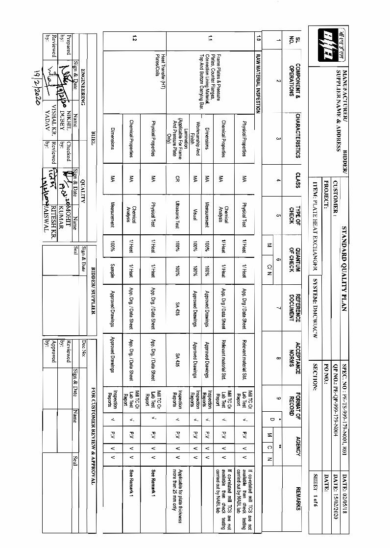
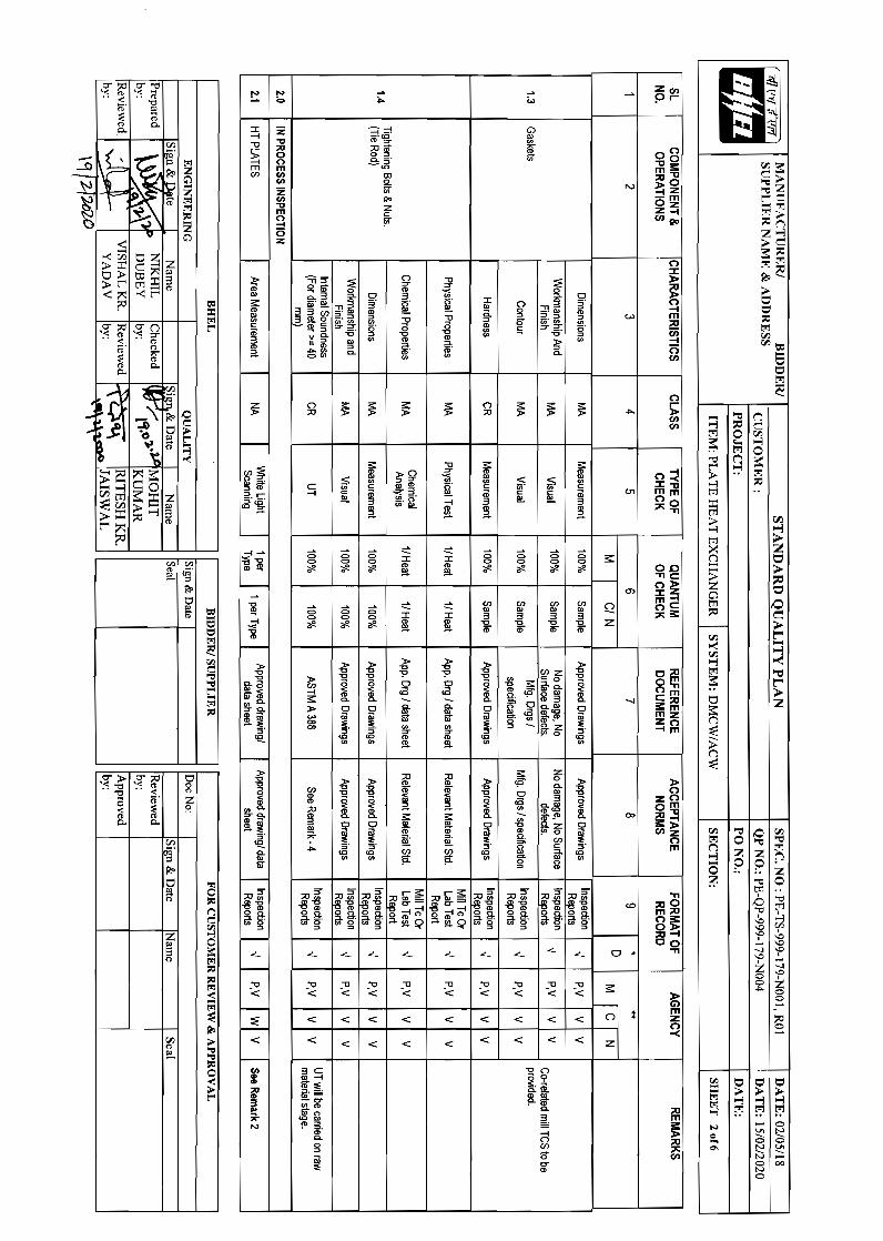
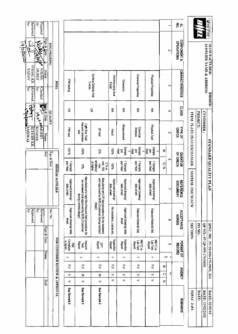
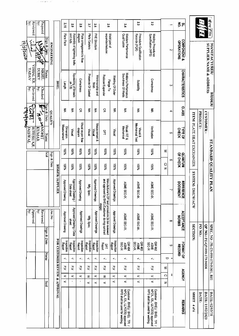
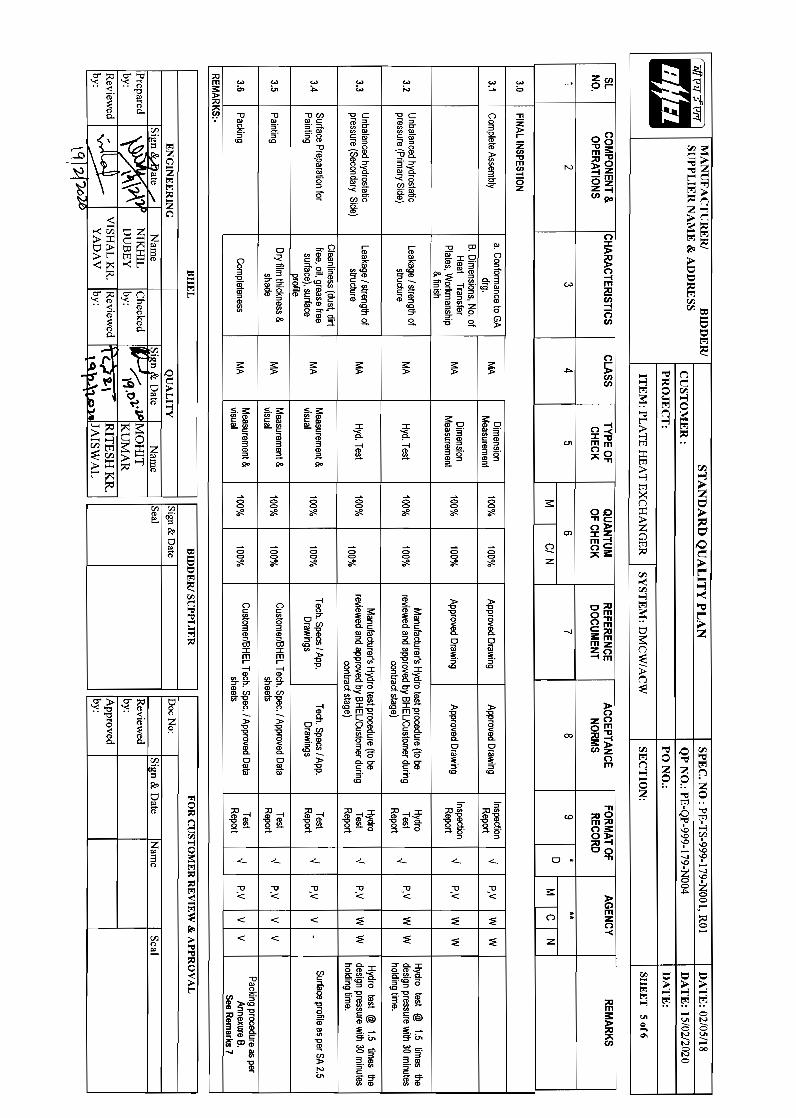
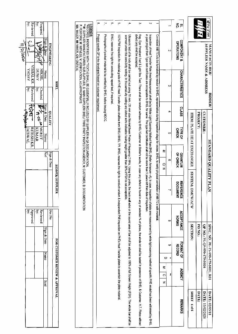
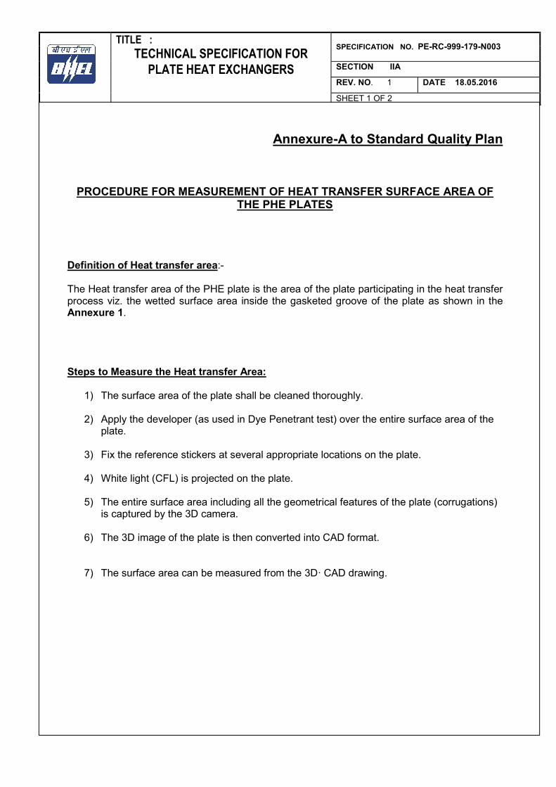
TITLE : SPECIFICATION NO. PE-RC-999-179-N003 TECHNICAL SPECIFICATION FOR
PLATE HEAT EXCHANGERS SECTION IIA
REV. NO. 1 DATE 18.05.2016
SHEET 1 OF 2
Annexure-A to Standard Quality Plan
PROCEDURE FOR MEASUREMENT OF HEAT TRANSFER SURFACE AREA OF THE PHE PLATES
Definition of Heat transfer area:- The Heat transfer area of the PHE plate is the area of the plate participating in the heat transfer process viz. the wetted surface area inside the gasketed groove of the plate as shown in the Annexure 1. Steps to Measure the Heat transfer Area:
1) The surface area of the plate shall be cleaned thoroughly.
2) Apply the developer (as used in Dye Penetrant test) over the entire surface area of the plate.
3) Fix the reference stickers at several appropriate locations on the plate.
4) White light (CFL) is projected on the plate.
5) The entire surface area including all the geometrical features of the plate (corrugations) is captured by the 3D camera.
6) The 3D image of the plate is then converted into CAD format.
7) The surface area can be measured from the 3D· CAD drawing.
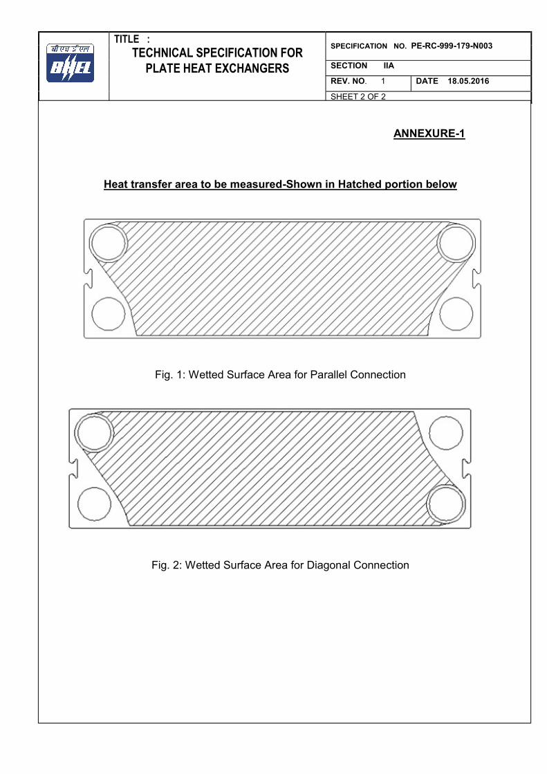
TITLE : SPECIFICATION NO. PE-RC-999-179-N003 TECHNICAL SPECIFICATION FOR
PLATE HEAT EXCHANGERS SECTION IIA
REV. NO. 1 DATE 18.05.2016
SHEET 2 OF 2
ANNEXURE-1
Heat transfer area to be measured-Shown in Hatched portion below
Fig. 1: Wetted Surface Area for Parallel Connection
Fig. 2: Wetted Surface Area for Diagonal Connection
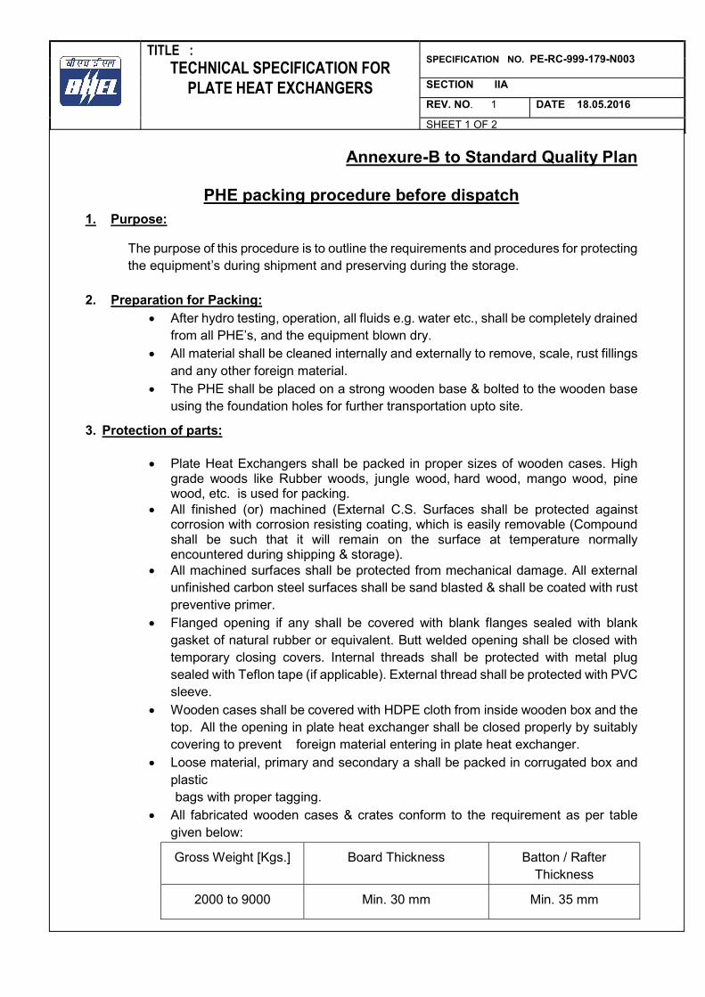
TITLE : SPECIFICATION NO. PE-RC-999-179-N003 TECHNICAL SPECIFICATION FOR
PLATE HEAT EXCHANGERS SECTION IIA
REV. NO. 1 DATE 18.05.2016
SHEET 1 OF 2
Annexure-B to Standard Quality Plan
PHE packing procedure before dispatch 1. Purpose:
The purpose of this procedure is to outline the requirements and procedures for protecting the equipment’s during shipment and preserving during the storage.
2. Preparation for Packing: After hydro testing, operation, all fluids e.g. water etc., shall be completely drained
from all PHE’s, and the equipment blown dry. All material shall be cleaned internally and externally to remove, scale, rust fillings
and any other foreign material. The PHE shall be placed on a strong wooden base & bolted to the wooden base
using the foundation holes for further transportation upto site.
3. Protection of parts:
Plate Heat Exchangers shall be packed in proper sizes of wooden cases. High grade woods like Rubber woods, jungle wood, hard wood, mango wood, pine wood, etc. is used for packing.
All finished (or) machined (External C.S. Surfaces shall be protected against corrosion with corrosion resisting coating, which is easily removable (Compound shall be such that it will remain on the surface at temperature normally encountered during shipping & storage).
All machined surfaces shall be protected from mechanical damage. All external unfinished carbon steel surfaces shall be sand blasted & shall be coated with rust preventive primer.
Flanged opening if any shall be covered with blank flanges sealed with blank gasket of natural rubber or equivalent. Butt welded opening shall be closed with temporary closing covers. Internal threads shall be protected with metal plug sealed with Teflon tape (if applicable). External thread shall be protected with PVC sleeve.
Wooden cases shall be covered with HDPE cloth from inside wooden box and the top. All the opening in plate heat exchanger shall be closed properly by suitably covering to prevent foreign material entering in plate heat exchanger.
Loose material, primary and secondary a shall be packed in corrugated box and plastic
bags with proper tagging. All fabricated wooden cases & crates conform to the requirement as per table
given below:
Gross Weight [Kgs.] Board Thickness Batton / Rafter Thickness
2000 to 9000 Min. 30 mm Min. 35 mm
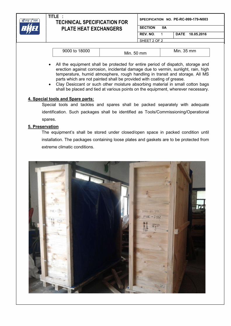
TITLE : SPECIFICATION NO. PE-RC-999-179-N003 TECHNICAL SPECIFICATION FOR
PLATE HEAT EXCHANGERS SECTION IIA
REV. NO. 1 DATE 18.05.2016
SHEET 2 OF 2
9000 to 18000 Min. 50 mm Min. 35 mm
All the equipment shall be protected for entire period of dispatch, storage and
erection against corrosion, incidental damage due to vermin, sunlight, rain, high temperature, humid atmosphere, rough handling in transit and storage. All MS parts which are not painted shall be provided with coating of grease.
Clay Desiccant or such other moisture absorbing material in small cotton bags shall be placed and tied at various points on the equipment, wherever necessary.
4. Special tools and Spare parts:
Special tools and tackles and spares shall be packed separately with adequate
identification. Such packages shall be identified as Tools/Commissioning/Operational
spares.
5. Preservation The equipment’s shall be stored under closed/open space in packed condition until
installation. The packages containing loose plates and gaskets are to be protected from
extreme climatic conditions.
TITLE : SPECIFICATION NO. PE-RC-999-179-N003 TECHNICAL SPECIFICATION FOR
RATE CONTRACT OF PLATE HEAT EXCHANGERS SECTION III
REV. NO. 0 DATE 22/02/2020
SECTION III
IIIA COMPLIANCE CERTIFICATE (TO BE SUBMITTED BY BIDDER DURING TENDER STAGE).
IIIB GUARANTEE SCHDULE (TO BE SUBMITTED BY BIDDER
DURING TENDER STAGE). IIIC DATASHEET –B FORMAT (TO BE SUBMITTED BY
SUCESSFUL BIDDER AFTER AWARD OF CONTRACT).
TITLE : SPECIFICATION NO. PE-RC-999-179-N003
TECHNICAL SPECIFICATION FOR RATE CONTRACT OF SECTION IIIA
PLATE HEAT EXCHANGERS REV. NO. 0 DATE 22/02/2020
COMPLIANCE CERTIFICATE The bidder shall confirm compliance with following by signing/ stamping this compliance certificate and furnishing same with the offer
a.) The scope of supply, technical details, construction features, design parameters etc. shall be as per technical specification & there are no exclusions/ deviations with regard to same.
b.) QP/ test procedures shall be submitted in the event of order based on the guidelines given in the specification & QP enclosed therein. QP will be subject to BHEL/Customer approval in the event of order & customer hold points for inspection/ testing shall be marked in the QP at the contract stage. Inspection/ testing shall be witnessed as per same apart from review of various test certificates/ Inspection records etc. The charges for 3rd party inspection (Lloyds, TUV or equivalent) for imported components shall be included in the base price of the equipment by the bidder.
c.) All drawings/data – sheets etc. to be submitted during contract shall be subject to BHEL/Customer review/ approval. GA drawings, as submitted with offer at tender stage are for reference purpose only and shall be subject to approval during contract stage.
d.) There are no other deviations with respect to specification other than those furnished in the ‘Schedule of Deviations’
e.) The offered materials shall be either equivalent or superior to those specified. Also for components where material is not specified it shall be suitable for intended duty, materials shall be subject to approval in the event of order.
f.) The commissioning spares (if any) are supplied on ‘As Required Basis’ & prices for same included in the base price (If bidders reply to this is “No commissioning spares are required” and if some spares are actually required during commissioning same shall be supplied by bidder without any cost to BHEL).
g.) All sub vendors shall be subject to BHEL/CUSTOMER approval.
h.) Any special tools & tackles, if required, shall be in bidder’s scope.
i.) Performance Guarantees for PHE’s shall stand valid as per commercial terms and conditions.
j.) Regarding bidder’s association with their respective Principals ( Plate & Gasket supplier ) bidder confirms the following: i. Plate supplier shall vet the thermal design of PHE at tender and contract stage and certify the
adequacy of design and number of plates. ii. Guarantee schedule duly vetted by Principal shall be submitted during contract stage. iii. Bidders have back to back arrangement with their principal for technical guarantees.
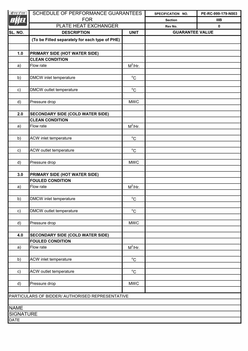
SPECIFICATION NO. PE-RC-999-179-N003
Section IIIB
Rev No. 0
SL. NO. DESCRIPTION UNIT
(To be Filled separately for each type of PHE)
1.0 PRIMARY SIDE (HOT WATER SIDE)
CLEAN CONDITION
a) Flow rate M3/Hr.
b) DMCW inlet temperature oC
c) DMCW outlet temperature oC
d) Pressure drop MWC
2.0 SECONDARY SIDE (COLD WATER SIDE)
CLEAN CONDITION
a) Flow rate M3/Hr.
b) ACW inlet temperature oC
c) ACW outlet temperature oC
d) Pressure drop MWC
3.0 PRIMARY SIDE (HOT WATER SIDE)
FOULED CONDITION
a) Flow rate M3/Hr.
b) DMCW inlet temperature oC
c) DMCW outlet temperature oC
d) Pressure drop MWC
4.0 SECONDARY SIDE (COLD WATER SIDE)
FOULED CONDITION
a) Flow rate M3/Hr.
b) ACW inlet temperature oC
c) ACW outlet temperature oC
d) Pressure drop MWC
PARTICULARS OF BIDDER/ AUTHORISED REPRESENTATIVE
NAMESIGNATUREDATE
GUARANTEE VALUE
PLATE HEAT EXCHANGER
SCHEDULE OF PERFORMANCE GUARANTEESFOR
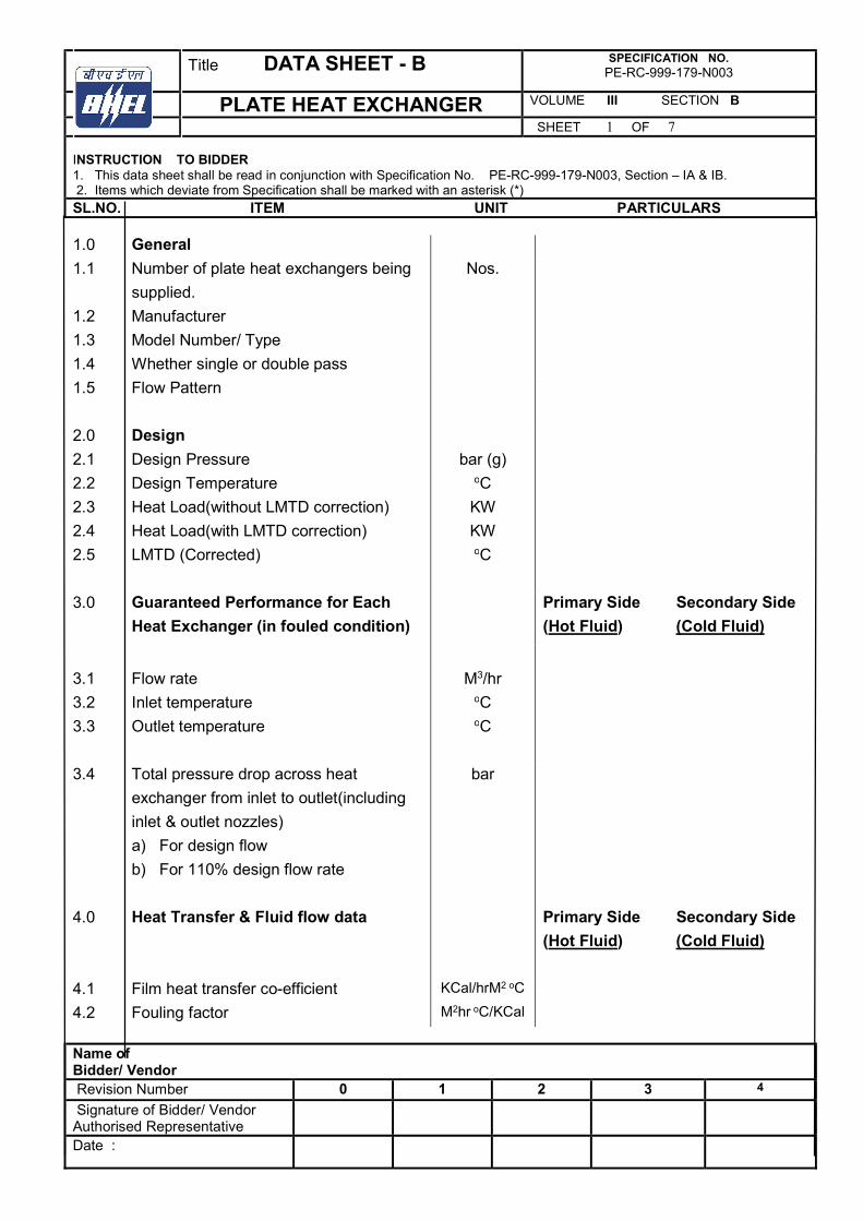
Title DATA SHEET - B SPECIFICATION NO. PE-RC-999-179-N003
PLATE HEAT EXCHANGER VOLUME III SECTION B
SHEET 1 OF 7 INSTRUCTION TO BIDDER 1. This data sheet shall be read in conjunction with Specification No. PE-RC-999-179-N003, Section – IA & IB. 2. Items which deviate from Specification shall be marked with an asterisk (*)
SL.NO. ITEM UNIT PARTICULARS
Name of Bidder/ Vendor Revision Number 0 1 2 3 4
Signature of Bidder/ Vendor Authorised Representative
Date :
1.0 General
1.1 Number of plate heat exchangers being
supplied.
Nos.
1.2 Manufacturer
1.3 Model Number/ Type
1.4 Whether single or double pass
1.5 Flow Pattern
2.0 Design
2.1 Design Pressure bar (g)
2.2 Design Temperature oC
2.3 Heat Load(without LMTD correction) KW
2.4 Heat Load(with LMTD correction) KW
2.5 LMTD (Corrected)
oC
3.0 Guaranteed Performance for Each
Heat Exchanger (in fouled condition)
Primary Side Secondary Side
(Hot Fluid) (Cold Fluid)
3.1 Flow rate M3/hr
3.2 Inlet temperature oC
3.3 Outlet temperature
oC
3.4 Total pressure drop across heat
exchanger from inlet to outlet(including
inlet & outlet nozzles)
a) For design flow
b) For 110% design flow rate
bar
4.0 Heat Transfer & Fluid flow data
Primary Side Secondary Side
(Hot Fluid) (Cold Fluid)
4.1 Film heat transfer co-efficient KCal/hrM2 oC
4.2 Fouling factor M2hr oC/KCal
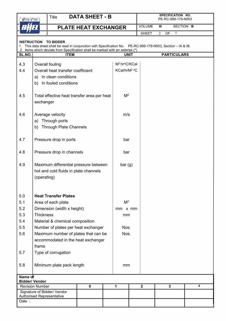
Title DATA SHEET - B SPECIFICATION NO. PE-RC-999-179-N003
PLATE HEAT EXCHANGER VOLUME III SECTION B
SHEET 2 OF 7 INSTRUCTION TO BIDDER 1. This data sheet shall be read in conjunction with Specification No. PE-RC-999-179-N003, Section – IA & IB. 2. Items which deviate from Specification shall be marked with an asterisk (*)
SL.NO. ITEM UNIT PARTICULARS
Name of Bidder/ Vendor Revision Number 0 1 2 3 4
Signature of Bidder/ Vendor Authorised Representative
Date :
4.3 Overall fouling M2 hroC/KCal
4.4 Overall heat transfer coefficient
a) In clean conditions
b) In fouled conditions
KCal/hrM2 oC
4.5 Total effective heat transfer area per heat
exchanger
M2
4.6 Average velocity
a) Through ports
b) Through Plate Channels
m/s
4.7 Pressure drop in ports
bar
4.8 Pressure drop in channels
bar
4.9 Maximum differential pressure between
hot and cold fluids in plate channels
(operating)
bar (g)
5.0 Heat Transfer Plates
5.1 Area of each plate M2
5.2 Dimension (width x height) mm x mm
5.3 Thickness mm
5.4 Material & chemical composition
5.5 Number of plates per heat exchanger Nos.
5.6 Maximum number of plates that can be
accommodated in the heat exchanger
frame
Nos.
5.7 Type of corrugation
5.8 Minimum plate pack length mm
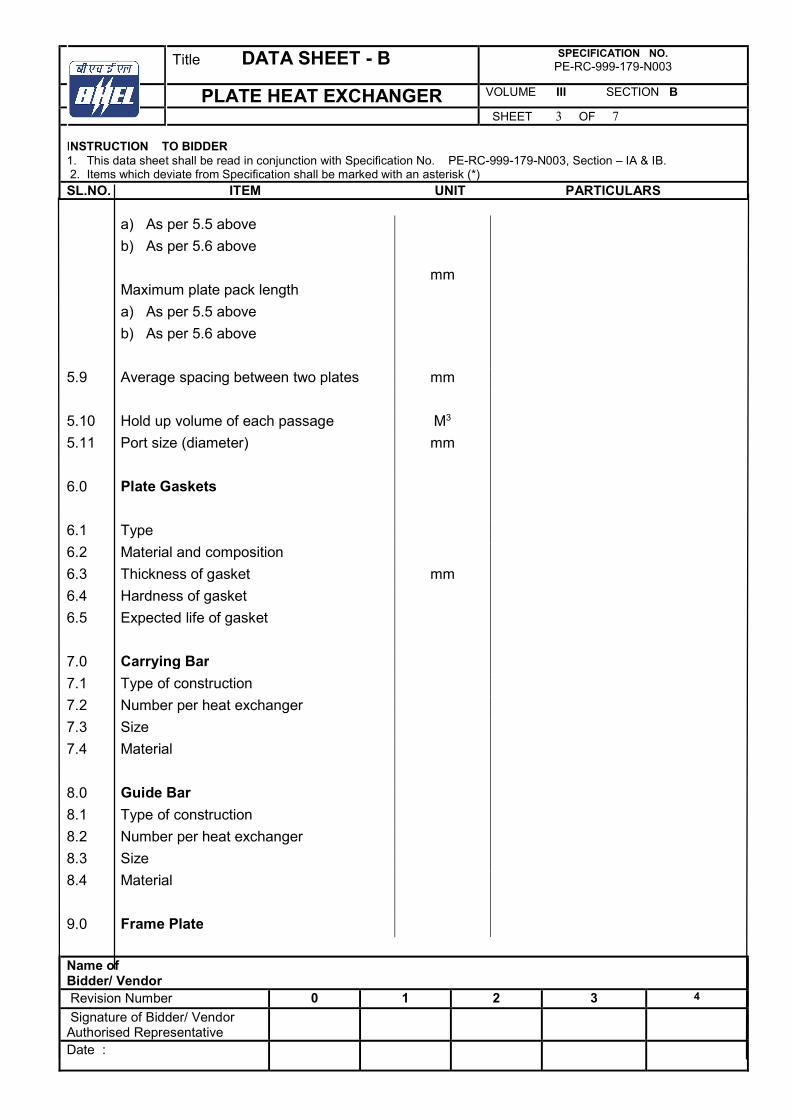
Title DATA SHEET - B SPECIFICATION NO. PE-RC-999-179-N003
PLATE HEAT EXCHANGER VOLUME III SECTION B
SHEET 3 OF 7 INSTRUCTION TO BIDDER 1. This data sheet shall be read in conjunction with Specification No. PE-RC-999-179-N003, Section – IA & IB. 2. Items which deviate from Specification shall be marked with an asterisk (*)
SL.NO. ITEM UNIT PARTICULARS
Name of Bidder/ Vendor Revision Number 0 1 2 3 4
Signature of Bidder/ Vendor Authorised Representative
Date :
a) As per 5.5 above
b) As per 5.6 above
Maximum plate pack length
a) As per 5.5 above
b) As per 5.6 above
mm
5.9 Average spacing between two plates mm
5.10 Hold up volume of each passage M3
5.11 Port size (diameter)
mm
6.0 Plate Gaskets
6.1 Type
6.2 Material and composition
6.3 Thickness of gasket mm
6.4 Hardness of gasket
6.5 Expected life of gasket
7.0 Carrying Bar
7.1 Type of construction
7.2 Number per heat exchanger
7.3 Size
7.4 Material
8.0 Guide Bar
8.1 Type of construction
8.2 Number per heat exchanger
8.3 Size
8.4 Material
9.0 Frame Plate
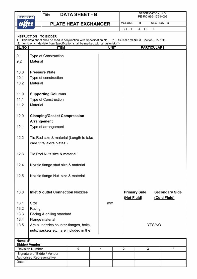
Title DATA SHEET - B SPECIFICATION NO. PE-RC-999-179-N003
PLATE HEAT EXCHANGER VOLUME III SECTION B
SHEET 4 OF 7 INSTRUCTION TO BIDDER 1. This data sheet shall be read in conjunction with Specification No. PE-RC-999-179-N003, Section – IA & IB. 2. Items which deviate from Specification shall be marked with an asterisk (*)
SL.NO. ITEM UNIT PARTICULARS
Name of Bidder/ Vendor Revision Number 0 1 2 3 4
Signature of Bidder/ Vendor Authorised Representative
Date :
9.1 Type of Construction
9.2 Material
10.0 Pressure Plate
10.1 Type of construction
10.2 Material
11.0 Supporting Columns
11.1 Type of Construction
11.2 Material
12.0 Clamping/Gasket Compression
Arrangement
12.1 Type of arrangement
12.2 Tie Rod size & material (Length to take
care 25% extra plates )
12.3
12.4
12.5
Tie Rod Nuts size & material
Nozzle flange stud size & material
Nozzle flange Nut size & material
13.0 Inlet & outlet Connection Nozzles
Primary Side Secondary Side
(Hot Fluid) (Cold Fluid)
13.1 Size mm
13.2 Rating
13.3 Facing & drilling standard
13.4 Flange material
13.5 Are all nozzles counter-flanges, bolts,
nuts, gaskets etc., are included in the
YES/NO
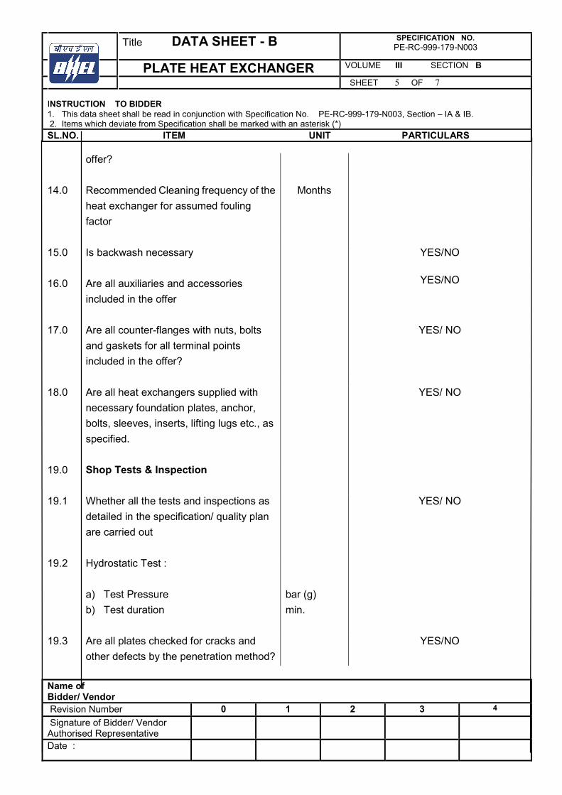
Title DATA SHEET - B SPECIFICATION NO. PE-RC-999-179-N003
PLATE HEAT EXCHANGER VOLUME III SECTION B
SHEET 5 OF 7 INSTRUCTION TO BIDDER 1. This data sheet shall be read in conjunction with Specification No. PE-RC-999-179-N003, Section – IA & IB. 2. Items which deviate from Specification shall be marked with an asterisk (*)
SL.NO. ITEM UNIT PARTICULARS
Name of Bidder/ Vendor Revision Number 0 1 2 3 4
Signature of Bidder/ Vendor Authorised Representative
Date :
offer?
14.0 Recommended Cleaning frequency of the
heat exchanger for assumed fouling
factor
Months
15.0
16.0
Is backwash necessary
Are all auxiliaries and accessories
included in the offer
YES/NO
YES/NO
17.0 Are all counter-flanges with nuts, bolts
and gaskets for all terminal points
included in the offer?
YES/ NO
18.0 Are all heat exchangers supplied with
necessary foundation plates, anchor,
bolts, sleeves, inserts, lifting lugs etc., as
specified.
YES/ NO
19.0 Shop Tests & Inspection
19.1 Whether all the tests and inspections as
detailed in the specification/ quality plan
are carried out
YES/ NO
19.2 Hydrostatic Test :
a) Test Pressure
b) Test duration
bar (g)
min.
19.3 Are all plates checked for cracks and
other defects by the penetration method?
YES/NO
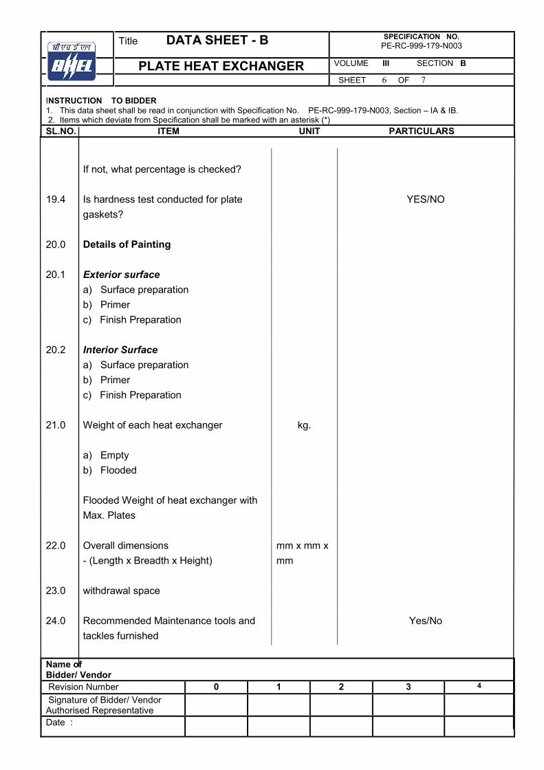
Title DATA SHEET - B SPECIFICATION NO. PE-RC-999-179-N003
PLATE HEAT EXCHANGER VOLUME III SECTION B
SHEET 6 OF 7 INSTRUCTION TO BIDDER 1. This data sheet shall be read in conjunction with Specification No. PE-RC-999-179-N003, Section – IA & IB. 2. Items which deviate from Specification shall be marked with an asterisk (*)
SL.NO. ITEM UNIT PARTICULARS
Name of Bidder/ Vendor Revision Number 0 1 2 3 4
Signature of Bidder/ Vendor Authorised Representative
Date :
If not, what percentage is checked?
19.4 Is hardness test conducted for plate
gaskets?
YES/NO
20.0 Details of Painting
20.1 Exterior surface
a) Surface preparation
b) Primer
c) Finish Preparation
20.2 Interior Surface
a) Surface preparation
b) Primer
c) Finish Preparation
21.0 Weight of each heat exchanger
a) Empty
b) Flooded
kg.
Flooded Weight of heat exchanger with
Max. Plates
22.0 Overall dimensions
- (Length x Breadth x Height)
mm x mm x
mm
23.0 withdrawal space
24.0 Recommended Maintenance tools and
tackles furnished
Yes/No
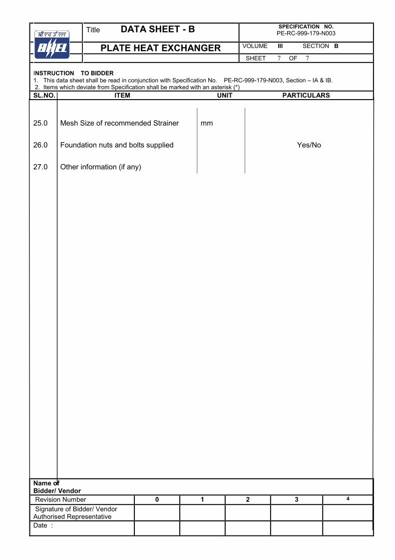
Title DATA SHEET - B SPECIFICATION NO. PE-RC-999-179-N003
PLATE HEAT EXCHANGER VOLUME III SECTION B
SHEET 7 OF 7 INSTRUCTION TO BIDDER 1. This data sheet shall be read in conjunction with Specification No. PE-RC-999-179-N003, Section – IA & IB. 2. Items which deviate from Specification shall be marked with an asterisk (*)
SL.NO. ITEM UNIT PARTICULARS
Name of Bidder/ Vendor Revision Number 0 1 2 3 4
Signature of Bidder/ Vendor Authorised Representative
Date :
25.0 Mesh Size of recommended Strainer
mm
26.0 Foundation nuts and bolts supplied
Yes/No
27.0 Other information (if any)
Related Documents