PE-K pellet boiler 35 to 90 kW Installation PE-K installation 35 to 90 kW 2012-02 2012-02-18 EN

Welcome message from author
This document is posted to help you gain knowledge. Please leave a comment to let me know what you think about it! Share it to your friends and learn new things together.
Transcript
PE-K pellet boiler 35 to 90 kW
Installation
PE-K installation 35 to 90 kW 2012-02
2012-02-18 EN

2 www.eta.co.atSubject to change due to technical improvements
Conditions for warranty, guarantee, liability .... 4
Data and dimensions .................................. 6
Regulations, standards and guidelines ............ 7
Boiler room ............................................. 8
Electrical connection .................................. 9
Energy-saving pumps ................................. 9
Chimney .................................................10 Basics ................................................... 10 Dimensioning, requirements ........................ 11 Requirements, connecting pipe .................... 12 Deflagration damper ................................. 13
Water hardness and corrosion .....................14
Air venting, compensation, system separation .15
Return riser and safety devices ....................16
Buffer ....................................................18 Hydraulic integration ................................. 20 Hydraulic integration of several buffers ........... 21 Parallel buffers with internal Tichelmann ........ 22 Parallel buffers with external Tichelmann ........ 23 Serial buffers ........................................... 24
Installation .............................................26 Minimum clearances for maintenance............. 26 Installing the stoker .................................. 27 Attaching the pellet bin .............................. 28 Flue gas recirculation ................................. 29 Connecting cables ..................................... 32 Attach pellet hoses ................................... 33 Attaching housing/panels ...........................34 Installing the ash box ................................ 35
Terminal diagram .....................................38
Remote control ........................................40 Requirements ..........................................40 Login data, network cable .......................... 41 Network settings ...................................... 42 Registering the touchscreen ......................... 43
Contents
Meanings of symbols
Important NOTICES for operation.
CAUTION: Failure to observe these notices can result in property damage.
STOP: Failure to observe these notices can result in personal injury.
Pellet store ............................................45 Delivery, storage room, boiler room ............... 45 Discharge conveyor with screw .....................46 Discharge conveyor with suction heads ........... 47 Demands on the storage room .....................48 Calculating supply and store size ................... 49 Filling nozzle, earthing, electricity ................. 50 Dust-tight door, no cables/pipes ................... 52 Tilted floor ............................................. 53
Checklist.................................................54
Commissioning ........................................55
Dismantling, disposal ................................55
Safety instructions ....................................60

3PE-K installation 35 to 90 kW 2012-02
Preface
Dear Customer
The satisfactory function of your new heating system depends to a large extent on its installation. So before starting the installation, please invest 15 minutes to get an overview with this manual.
Warranty and guarantee
You should also read the "Conditions for warranty, guarantee, liability" on page 4 carefully. All of the requirements we impose are intended to prevent damage that neither you nor we wish to occur.
Training the customer
To avoid errors in operation, please explain to your customer (preferably using the user manual) exactly how the new heating system works and how it should be operated and maintained.
Extended warranty for commissioning performed by an authorised partner company
Commissioning by an expert ensures high efficiency, clean combustion and safe operation. For these reasons, if your newly installed boiler is commis-sioned by an authorised partner company or one of our customer service employees, we offer an extended warranty. Refer to our warranty conditions in effect at the time of purchase.
Connecting the boiler to the Internet
The boiler can be operated remotely (mobile phone, PC, ...) via the Internet. For this purpose, a LAN cable from the Internet modem to the boiler is needed.
Service agreement
You can ensure the best care for the heating system by taking out a service agreement with one of our certified contractors or our own customer service.
4 www.eta.co.atSubject to change due to technical improvements
Conditions for warranty, guarantee, liability
Conditions for warranty, guarantee, liability
We can only guarantee and accept liability for the function of our boiler if it is properly installed and operated.
Requirement for warranty, guarantee and liability is that this boiler be used in accordance with its intended purpose, only for heating and hot water supply with no more than 2,000 full-load hours annually, and, in particular, that the following general conditions be observed during installation and operation:
For set-up, a dry room is required. In particular, only condensation dryers may be used as clothes dryers in the same room.
Local building and fi re protection regulations must be observed.
The boiler is suitable for use with wood pellets according to ÖNORM M 7135, DIN 51731, EN 14961-2 class A1, EN plus class A1 or DINplus with a diameter of 6 to 8 mm and a length of 15 to 40 mm. Operation with unsuitable fuels, in particular those containing halogens (chlorine) or high-slag pellets such as from grain waste, is not permitted.
The combustion air must be free of aggressive substances such as chlorine and fl uorine from solvents, cleaning agents, adhesives and propellants, or ammonia from cleaning agents, to prevent corrosion of the boiler and chimney.
Water is the intended heat-transfer medium. For special anti-frost requirements, up to 30% glycol may be added. Softened water is required for the initial fi ll-up of the heating system and for refi lling after repairs. For the initial fi ll-up of the heating system, the value of 20,000 lt°dH for the system volume in litres multiplied by the hardness (in degrees of German hardness) may not be exceeded. The pH value should be set between 8 and 9. Addition of hard water should be minimised to limit limescale build-up in the boiler. Set enough shut-off valves to avoid bleeding large amounts
of water during repairs. Any leaks in the system must be repaired at once.
The combustion air must be free of aggressive substances such as chlorine and fl uorine from solvents, cleaning agents, adhesives and propellants, or ammonia from cleaning agents, to prevent corrosion of the boiler and chimney.
A safety valve (3 bar) as protection against excess pressure and a thermal relief valve (95 °C) to protect against overheating must be installed by the contractor.
To protect against air suction if the system cools off, an expert must provide a suffi ciently large expansion tank or a pressure maintenance system. Suffi cient air venting must also be ensured. Open expansion tanks or underfl oor heating with permeable piping also have a high air intake, resulting in above-average boiler corrosion. Corrosion damage to the boiler due to improper air venting or high air intake is excluded from warranty, guarantee and liability.
Operation at lower power than the lowest power specifi ed on the type plate is not permitted. For design outputs that are considerably less than the boiler's rated output, either a reduction of the heating time slots or a buffer storage tank is required.
Only components provided by us may be used for expansion of the control system, except for commonly used units such as thermostats.
Cleaning and maintenance are required as specifi ed in the user manual.
Repairs are only permitted with spare parts provided by us. The only exceptions are common standardised parts such as electrical fuses or fastening materials, as long as they possess the required features and do not restrict the functionality of the system.

5PE-K installation 35 to 90 kW 2012-02
Conditions for warranty, guarantee, liability
The installing contractor is liable for proper installation according to the boiler's installation instructions and the relevant rules and safety regulations. If you as customer have installed the heating system partly or entirely without relevant training and in particular without up-to-date practical experience, without having the installation checked by a trained and responsible expert, we exclude defects in our delivery and consequential damages resulting from this cause from our warranty, guarantee and liability.
For repair of defects carried out by the customer or by third parties, ETA only bears the costs or remains obligated by warranty if this work was approved in advance by the customer service of ETA Heiztechnik GmbH.
Subject to technical alterations
We reserve the right to make technical modifi cations without notice. Printing and typesetting errors or changes of any kind made in the interim are not cause for claims. Individual confi gurations depicted or described here are only optionally available. In the event of contradictions between individual documents regarding delivery scope, the information in our current price list applies.

6 www.eta.co.atSubject to change due to technical improvements
Data and dimensions
Data and dimensions
PE-K pellet boiler 35 50 70 90Rated capacity kW 9.4 - 35.0 14.1 - 49.0 21.0 - 70.0 28.4 - 95.0
Efficiency at partial/full load – wood pellets* % 90.8 / 94.1 93.1 / 93.5 92.3 / 93.3 91.6 / 93.0
Dimensions without casing, W x D x H mm 610 x 1,100 x 1,557 710 x 1,249 x 1,758
Weight with/without stoker kg 705 / 601 706 / 602 965 / 861 967 / 863
Water content Litres 117 196
Water-side pressure drop (ΔT = 20 °C) Pa / mH2O
280 / 0.028 550 / 0.055 480 / 0.048 880 / 0.088
Pellet bin on boiler (net) kg 60 (295 kWh)
Maximum distance to pellet store m 20
Ash box volume Litres 35 44
Flue gas mass flow rate, partial/full load g/s 8.3 / 21.3 11.5 / 30.0 17.5 / 42.8 21.8 / 58.0
CO2 content in dry flue gas, partial/full load* % 9.0 / 13.0 9.5 / 13.0 10.0 / 14.0 11.0 / 14.0
Exhaust temperature, partial/full load* °C 80 / 115 85 / 140 85 / 140 90 / 145
Flue draught 2 Pa at partial load / 5 Pa at full load required. Draught limiter required for flue draught over 15 Pa.
Carbon monoxide (CO) emissions partial/full load*
mg/MJ mg/m³ 13% O2
55 / 16 84 / 24
50 / 13 76 / 20
36 / 8 55 / 12
24 / 3 38 / 4
Dust emissions, full load* mg/MJ mg/m³ 13% O2
4 8
12 18
10 16
4 / 8 7 / 13
Unburned hydrocarbons (CxHy) partial/full load*
mg/MJ mg/m³ 13% O2
1 / <1 2 / 1
1 / <1 1 / <1
<1 / <1 <1 / <1
<1 / <1 <1 / <1
Electrical power consumption partial/full load* W 69 / 159 78 / 153 90 / 190 95 / 206
Maximum permissible operating pressure 3 bar Temperature adjustment range 70° - 85 °C Maximum permissible operating temperature 95 °C Minimum return temperature 60 °C
Boiler class 3 according to EN 303-5 Tested fuel Beech up to W20 Electrical connection 1 x 230 V / 50 Hz / 13 A
* Data from test reports of BLT Wieselburg, report numbers 053/06, 054/06 and 043/10. The test reports from the BLT Wieselburg test lab can be found on the Internet at: blt.josephinum.at
7PE-K installation 35 to 90 kW 2012-02
Regulations, standards and guidelines
Regulations, standards and guidelines
Before setting up the boiler system, consult the responsible chimney sweep
Standards and guidelines
• VDI 2035, prevention of damage due to corrosion and scaling in hot-water heating systems with flow temperatures up to 120°C. Instead of the maximum hardness of 11.2 dH for 20 to 50 lt/kW specific system volume, the maximum lime content of the initial fill-up for boilers up to 90 kW is limited to 20,000 lt°dH (system volume in litres multiplied by the hardness in degrees of German hardness).
• EN 12828, heating systems in buildings - planning for hot-water heating systems. The safety temperature limiter (100°C) is already installed in the boiler described here. The contractor must install a sufficiently large expansion tank (at least 10% of the system volume), a safety valve, a water shortage alert or minimum pressure limiter and a thermal emer-gency cooling valve.
• EN 12831, heating systems in buildings - method for calculating standard heating load
• EN 13384, flue systems - thermal and fluid-dynamic calculation methods
• Only in Germany, DIN 18160, flue systems - planning and design
• Only in Austria, ÖNORM H 5170, heating systems - construction and fire safety requirements
The boiler complies with
98/37/EG Machinery directive
89/106/EWG Regulations for building products
73/23/EWG Low voltage directive
89/336/EWG EMC directive
93/68/EWG Amendment to 73/23/EWG and 89/336/EWG
EN 287-1 Certification of welders
EN 303-5 Heating boilers for solid fuels
EN 60335-1/A1:96 Safety of electrical appliances
IEC 61000-6 3,4:01 EMC emitted interference
IEC 61000-6 1,2:01 EMC immunity
Conformity has been demonstrated. The relevant documents and the original declaration of conformity (CE) are in the manufacturer's files.
Regulations
• State building regulations
• Industrial and fire safety regulations
• State fire regulations
• In Germany, the EnEG (Energy Saving Act) with its enacted EnEV ordinances for energy-saving insula-tion and energy-saving building technologies
• In Germany, 1.BImSchV, initial ordinance for enforcement of the federal pollution control act for small-scale furnaces.
• In Austria, Article 15 a, agreement on protective measures regarding small-scale furnaces
• In Austria, Article 15 a, agreement on saving energy
• In Switzerland, VKF/AEAI fire safety regulations 25-03 and 106-03
8 www.eta.co.atSubject to change due to technical improvements
Boiler room
Boiler room
Requirements for the surroundings
The boiler may only be installed in dry surroundings. The permitted ambient temperatures are between 5 and 30°C.
Ash
The ash must be kept in non-fl ammable containers with covers.
Fire extinguisher
In Austria at least a powder extinguisher ABC 6 kg is required. Better is a foam extinguisher AB 9 litre, which causes less damage when extinguishing.
The fi re extinguisher should be kept outside the boiler room, easily visible and easily accessible.
In Germany and Switzerland, no fi re extinguishers are required for heating systems in private residences. In spite of this, we recommend having one in the house.
No heating appliances in the vicinity of escape routes
No boiler may be installed in stairwells, hallways or rooms through which escape routes lead to the outside.
Installation or boiler room
A boiler room is required in Germany for 50 kW or more, and in Switzerland for over 20 kW. Different laws apply in the individual Austrian states (boiler room in Upper Austria from 15 kW; Styria from 18 kW; Lower Austria from 26 kW; Salzburg from 35 kW; Burgenland, Tyrolia, Vorarlberg and Vienna from 50 kW; for Carinthia a boiler room is required for all central heating systems).
Boiler room
A boiler room must be built with fi re-resistant walls and ceilings F90 (EI90), in Switzerland El30 up to 70 kW and EI60 above 70 kW. An escape door to a corridor or to the outside is required. The door F30 (El30) must open in the direction of escape and be self-closing with a tight seal. Boiler room doors that open into escape routes must be F90 (EI90). In Germany there may be no connection to other rooms. Minimum cross-sections for air inlets and outlets are required.
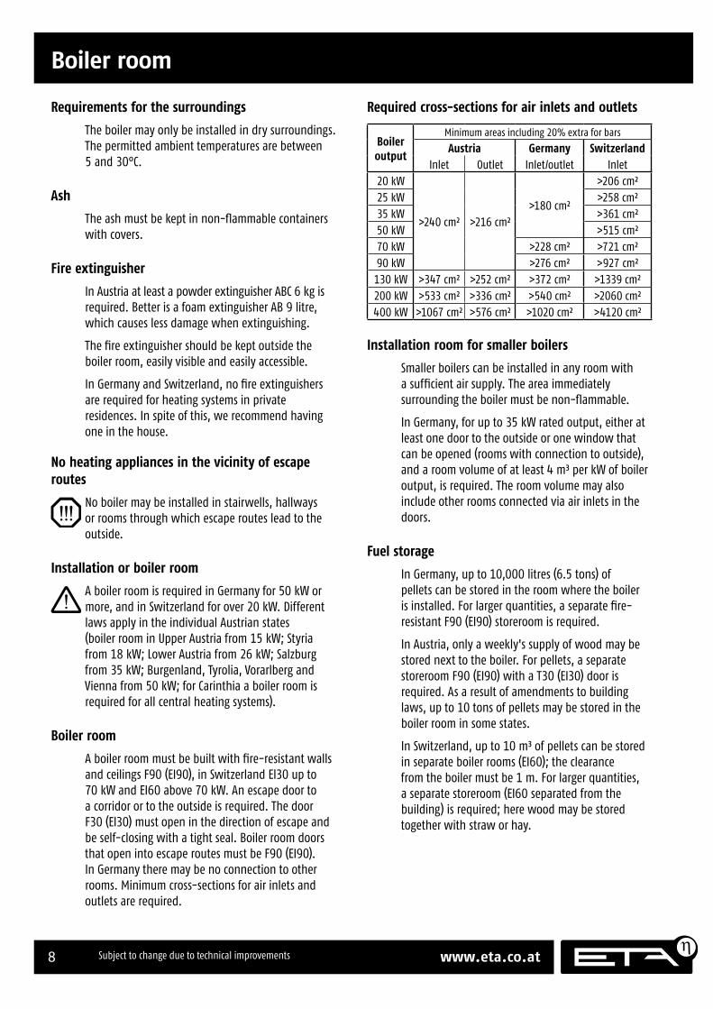
Required cross-sections for air inlets and outlets
Boiler output
Minimum areas including 20% extra for bars
Austria Germany SwitzerlandInlet Outlet Inlet/outlet Inlet
20 kW
>240 cm² >216 cm²>180 cm²
>206 cm²25 kW >258 cm²35 kW >361 cm²50 kW >515 cm²70 kW >228 cm² >721 cm²90 kW >276 cm² >927 cm²
130 kW >347 cm² >252 cm² >372 cm² >1339 cm²200 kW >533 cm² >336 cm² >540 cm² >2060 cm²400 kW >1067 cm² >576 cm² >1020 cm² >4120 cm²
Installation room for smaller boilers
Smaller boilers can be installed in any room with a suffi cient air supply. The area immediately surrounding the boiler must be non-fl ammable.
In Germany, for up to 35 kW rated output, either at least one door to the outside or one window that can be opened (rooms with connection to outside), and a room volume of at least 4 m³ per kW of boiler output, is required. The room volume may also include other rooms connected via air inlets in the doors.
Fuel storage
In Germany, up to 10,000 litres (6.5 tons) of pellets can be stored in the room where the boiler is installed. For larger quantities, a separate fi re-resistant F90 (EI90) storeroom is required.
In Austria, only a weekly's supply of wood may be stored next to the boiler. For pellets, a separate storeroom F90 (EI90) with a T30 (EI30) door is required. As a result of amendments to building laws, up to 10 tons of pellets may be stored in the boiler room in some states.
In Switzerland, up to 10 m³ of pellets can be stored in separate boiler rooms (EI60); the clearance from the boiler must be 1 m. For larger quantities, a separate storeroom (EI60 separated from the building) is required; here wood may be stored together with straw or hay.

9PE-K installation 35 to 90 kW 2012-02
Electrical connection Energy-saving pumps
Electrical connection
Energy-saving pumps
Not just for the subsidy
Many incentive programmes either demand energy-saving pumps and hydraulic calibration or grant extra bonuses for them. This is no coincidence, since a single heating circuit with an old pump uses up to 10% of the electricity in an average four-person household.
Energy-saving pumps
For an underfl oor heating system that needs a large amount of water circulation throughout the heating season, an electronic pump with a fi xed speed setting is suffi cient.
For individual room temperature control, the pump must react to the heating in individual rooms being switched on or off. It needs to adjust the amount of water and the delivery height to current demand. Differential pressure controlled energy saving pumps with "Energy Label A" can do that perfectly.
The pump built into the boiler is already a highly effi cient variable-speed pump.
Electrical connection
Observe the national regulations and any special regulations of local energy utilities.
Supply cable ?? x ?? mm² with fl exible wires ???????????????????????????
A circuit breaker in the mains power input is required.
Emergency stop switch
In Austria, heating systems installed in boiler rooms must be equipped with an emergency stop switch which may not affect the room's lighting. The switch must be situated immediately outside the access door and clearly marked. For boiler rooms that are only accessible from outdoors, these switches may also be within the boiler rooms, immediately next to the access doors.
In Germany, a boiler room is only necessary above 50 kW boiler output, so only then is an emergency stop switch also required.
A single-pole emergency stop switch is integrated into the boiler's safety chain. It only affects the combustion air supply. The pumps continue running to cool the boiler.
Supply cable 3 x 1.5 mm² with flexible wires 230 V AC / 50 Hz C13 A / L+N+PE

10 www.eta.co.atSubject to change due to technical improvements
Basics Chimney
For every boiler a chimney of its own
The better the boiler and the chimney are matched, the greater the energy of the fl ue gases leaving the chimney and thus the certainty that they will rise into the air from the top. If the diameter is too large, the chimney will not be heated suffi ciently and the exit velocity and temperature will be too low. The fl ue gas then lacks the energy to rise and in extreme cases, the smoke can sink down along the roof.
Chimneys with a diameter more than 50% greater than needed must be renovated to reduce the diameter.
If a chimney is designed for use with two simultaneously operating boilers, it may prove to be oversized for the partial load from only one boiler. If there is really only one chimney available, a buffer storage tank can help avoid a too-small partial load.
Chimney renovation - before it's too late
Compared to older boilers, modern ones are much more effi cient and have lower amounts of fl ue gas with considerably lower temperatures. The water in the fl ue gas condenses and destroys old masonry chimney walls, very slowly but also inexorably.
Timely renovation before the chimney wall has been destroyed can be performed quickly and easily by inserting a tube. But if the fl ue gas condensates have penetrated the mortar joints, then the entire fl ue must be dismantled and rebuilt.
Sewage connection for the chimney
For the condensation that forms in the chimney, a DN 25 sewer connection via trap is needed. The resulting amount of water is small. If no sewer connection is possible, then a bucket that is checked regularly can also be used.
A fan-assisted boiler and a gas-fi red boiler may not be connected to the same chimney
Most gas-fi red boilers do not have a sealed air fl ap and when the fan-assisted boiler is started while the chimney is cold, the fl ue gas is pushed through the gas boiler into the boiler room. Even a fl ue gas damper in the gas boiler's fl ue pipe will hardly help since these dampers are not certain to close with a good seal.
With atmospheric gas boilers, old fi reclay chimneys only stay dry with the gas boiler's overfl ow opening. The water from the fl ue gas condenses in the chimney. During pauses in fi ring, air fl ows through the overfl ow opening and dries the chimney. If this air stream is blocked by a fl ue gas damper, the moisture can destroy an old fi reclay chimney.
Fan-assisted boiler and wood-burning stove on the same chimney - a dangerous combination
This combination is not expressly forbidden, but it is dangerous.
Every wood-burning stove has an air intake through which any fan-assisted boiler, whether oil or wood, will blow fl ue gas into the living area through a cold chimney. If the wood-burning stove's fi rebox door is not closed and the boiler is defective at the same time, even acute carbon monoxide poisoning is possible.
The wood-burning stove needs a signifi cantly larger chimney cross section, which cannot be heated by the fan-assisted boiler. Cold fl ue gas does not rise from the opening; it sinks and can reach living quarters through open windows.
It may also be possible to hear the boiler's fan in the living quarters through the wood-burning stove.
Clarify with the chimney sweep
In any case, the chimney's suitability should be clarifi ed with the chimney sweep.
Chimney
Basics

11PE-K installation 35 to 90 kW 2012-02
Chimney Dimensioning, requirements
Obsolete regulations require the wrong chimney
Laws and regulations demand a fl ue system that is moisture-resistant for oil and gas and one that is resistant to soot fi res for solid fuels.
Wood is a solid fuel. But in the lower output range, the temperature of the fl ue gas can be under 100°C and condensates can be deposited in the chimney. So the chimney must be moisture-resistant, "against regulations". Whoever builds a chimney resistant to soot fi res can then look on helplessly as the condensate destroys the chimney wall.
Soot fi res are possible in natural-draught boilers or wood-burning stoves regulated by throttling the air supply. When the wood fi re is at full intensity and the boiler temperature has been reached, a thermostat closes the air fl ap. That stops the combustion, but since the combustion chamber temperature doesn't fall, the wood continues to gasify. Uncombusted wood gas condenses to tar in the chimney; the tar can be ignited by sparks from the fi re.
With modern lambda-controlled wood boilers, such a soot fi re is nearly impossible since the control system reduces the wood gasifi cation and not the air. In modern lambda-controlled pellet boilers, the control system shuts down the fi re by stopping the pellet supply without closing off the air supply. So there is no lack of air and no fl ammable tar in the chimney. The low exhaust temperatures of a modern boiler also provide no ignition source for a soot fi re. With a modern and properly maintained wood boiler, there is no danger to chimneys from soot fi res.
Moisture-resistant W3G fl ue systems
Since 2005 there are W3G chimneys (classifi ed according to the German DIN 18160), which are resistant to both moisture and soot fi res. These chimneys are approved for all fuels. Most of these W3G chimneys have ceramic inner pipes, which have a signifi cantly longer service life than metal chimneys due to their acid resistance.
Small chimney diameter required
Please note that for partial-load operation with fl ue gas temperature of only 100°C, the large chimney cross sections that were previously typical for solid fuel are no longer optimal. If the cross section is too large, the fl ue gas is no longer certain to rise from the chimney opening and may fl ow along the roof and sink to the windows of the living quarters.
INSERT TABLE!
Normally no defl agration damper
The boiler is designed with safety routines in the control system to prevent defl agrations, so no defl agration damper (also often called a blowback fl ap) is required if the connecting pipe is short and ascends to the chimney. If a defl agration damper is needed at high points before descending sections or at the beginning of a long horizontal section (L > 30 x D), it must be situated so that people are not endangered by a defl agration.
Dimensioning, requirements
Height above boiler room floor
Chimney diameter in cm (required minimum diameter)
35 kW 50 kW 70 kW 90 kW
6 m 20 cm 20 cm* 22 cm 22 cm
7 m 18 (16) cm 20 cm 22 cm 22 cm
8 m 18 (15) cm 18 (16) cm 22 cm 22 cm
9 m 18 (15) cm 18 (15) cm 20 (18) cm 20 (18) cm
10 m 16 (14) cm 18 (15) cm 20 (18) cm 20 (18) cm
11 m 16 (14) cm 18 (15) cm 20 (18) cm 20 (18) cm
12 m 16 (14) cm 18 (15) cm 20 (18) cm 20 (18) cm
Values on grey background: Connection from boiler to chimney with same cross-section as chimney.
*) For boiler outputs over 30 kW and low chimney heights, a chimney joint tilted 45° can help achieve the required draught of 5 Pa at full load with acceptable cross-sections (a size smaller than indi-cated in the table).

12 www.eta.co.atSubject to change due to technical improvements
Requirements, connecting pipe Chimney
Requirements, connecting pipe
Connecting pipe to chimney insulated
The connection between the boiler and the chimney should be insulated with at least 30 mm, preferably 50 mm, of mineral wool to avoid thermal losses that can lead to a build-up of condensation.
Cleaning aperture in the connecting pipe
Easily accessible cleaning apertures must be available for cleaning the fl ue pipe.
Install short, airtight and ascending connections
"Attractive" right-angle fl ue offsets with two or more bends are bad in a fl ue gas conduit. The optimum to strive for is the shortest pipe from the boiler to the chimney with a minimum of direction changes.
The fl ue gas conduit to the chimney must be leakproof (use heat-resistant silicone covered with pure aluminium adhesive tape to seal sleeved pipes without gaskets); otherwise smoke emission into the boiler room can be expected during ignition.
Install the fl ue gas conduit so it ascends toward the chimney!
Long, horizontal fl ue gas conduits to the chimney
Use a tight cross section, apply above-average insulation (50 mm and more) and provide enough cleaning apertures.
Calculations indicate that a connecting pipe with a large cross section would reduce the required chimney cross section. However, with low fl ow speeds ash deposits will form and then the theoretically calculated fl ue draught will be lost again.
With a large chimney cross section, the unbent length of the connecting pipe can be at maximum half of the effective chimney height (calculation required).
Chimney renovation with stainless steel pipe???
Maybe the chimney has already been renovated for oil or gas with a stainless steel pipe, and now a conversion to wood or pellets is planned. Or the chimney is too tight to install a ceramic pipe with a sure seal. If a moisture-resistant inner pipe is installed in a suffi ciently fi re-resistant casing, the German association of chimney sweeps has found the following solution to the standards and regulations dilemma:
"in the certifi cation of suitability and safe use for heating systems, it should be noted that after a soot fi re the long-term durability cannot be ensured and penetration of the chimney by moisture cannot be ruled out so that it may be necessary to replace the inner pipe (Criteria for Determination of Suitability and Safe Use of Heating Systems - October 29th 2008, page 12).
Replace inner pipe after a soot fi re
After a soot fi re, the inner pipe is in all likelihood no longer suffi ciently leakproof, making the chimney subject to damage by moisture so that the inner pipe needs to be replaced without fail, regardless of whether its resistance to soot fi res has been checked or not.
Fit the chimney connection just under the ceiling!
Even though the current boiler can be connected to the chimney at a low height, it is better if you fi t the chimney connection just below the ceiling. The fl ue pipe is easier to install, and the vertical connection pipe is long enough for an emission measurement.
Structure-borne noise
To avoid structure-borne noise, there should not be a fi xed connection between the fl ue pipe and the chimney!
Good exhaust systems are acoustically isolated. When steel pipes are connected to a fi reclay chimney, ceramic fi bre bandages have proven effective at preventing structure-borne noise as well as damage to the refractory sleeve.
13PE-K installation 35 to 90 kW 2012-02
Chimney Deflagration damper
Normally no deflagration damper up to 50 kW
The boiler is designed with safety routines in the control system to prevent deflagrations, so no defla-gration damper (also often called a blowback flap) is required if the connecting pipe is short and ascends to the chimney.
From 70 kW we recommend a deflagration damper
Deflagration damper for high points and long pipes
For high points before descending sections or at the beginning of a long horizontal section (L > 30 x D), a deflagration damper is required regardless of the boiler output.
Position deflagration dampers so that no people are endangered.
Deflagration damper

14 www.eta.co.atSubject to change due to technical improvements
Water hardness and corrosion
Water hardness and corrosion
Softened water and shut-off valves
If a buffer storage tank is installed in the heating system, the system should be fi lled with softened water. The lime is deposited on a very small area in the boiler and forms layers of insulating limescale. The boiler wall is no longer suffi ciently cooled and stress cracks can result. To keep the lime content to a minimum during minor repairs, shut-off valves are essential at all buffer connections and all heat distribution branches.
When is decalcifying necessary?
For the initial fi ll-up of the heating system with the boiler, the lime content of all water in the heating system may not exceed the value of 20,000 lt°dH (system volume in litres multiplied by the hardness in degrees of German hardness).
20,000 lt°dH = permitted hardness in °dH litres of water
Example: 20,000 lt°dH = 10 °dH 2000 litres
To maintain the limit of 20,000 lt°dH, the system must be softened to 10°dH.
Softening with a salt-regeneration ion exchanger
We recommend softening water with salt-regeneration ion exchangers, just as drinking water is softened. This method does not remove salt from the water. It exchanges the calcium in lime against sodium from the salt and has considerable advantages. It is cheap and chemically stable against contamination. In addition, it has a natural alkalinity that generally results in a suffi ciently non-corroding pH value of around 8.
pH value between 8 and 9 may require dosing with trisodium phosphate
If the heating water's pH value is not greater than 8 after a week of operation, increase it by adding 10 g/m³ of trisodium phosphate (Na3PO4) or 25 g/m³ of trisodium phosphate dodecahydrate (Na3PO4.12H2O). Wait another 2-4 weeks before making further corrections. The pH value may not exceed 9.
No hybrid installations
A disadvantage of salt-regeneration ion exchange is the salt content with its high electrical conductivity, which can lead to electrolytic corrosion, especially of aluminium or galvanized steel. If only steel, brass, gunmetal and copper are used in the heating system and the use of stainless steel is limited to small areas, then no corrosion problems should be expected even with salty water.
Inside a heating system, galvanized and aluminium parts are always in danger of corrosion, especially in combination with copper tubing. In practice this means no hot-galvanized fi ttings and no mix of galvanized tubing with copper tubing. There is an illogical exception: galvanized steel tubing combined with boilers or buffer storage tanks made of steel. Presumably the uniform zinc layer dissolves uniformly and is dispersed evenly throughout the system without localised corrosion.
Complete desalination not required
If there is no aluminium (heat exchanger in the gas boiler or aluminium radiator) in the system, then no expensive desalination with ion exchange cartridges or osmosis is required.
Lime stabilisation can be dangerous
The addition of lime stabilising agents prevents limescale. However, we advise against doing so. These agents increase the salt content and result in an undefi ned pH value. If large amounts of water are added, exactly the same agent must be used again. Mixing with other water additives or with antifreeze can result in corrosion.

15PE-K installation 35 to 90 kW 2012-02
Air venting, compensation, system separation
Air venting, compensation, system separation
Protect the expansion tank against shut-off
All shut-off valves along the path from the expansion tank to the boiler and to the buffer storage tank must be capped valves, or the hand wheels or levers must be removed from the valves (hang on the valve with a wire) to ensure that they cannot be closed by accident.
Adjust expansion tank pressure
Most expansion tanks are delivered with primary pressure of 1.5 bar. The pressure should be adjusted by releasing nitrogen so that it is 0.3 bar higher than the static pressure at the place of installation, but the pressure should not fall below 0.9 bar.
Example 1:height difference between expansion tank and highest point in the system pst = 11 m = 1.1 bar: 1.1 bar + 0.3 bar = 1.4 bar pressure setting. In this case, you can also contact our customer service to set the system's cut-off pressure to 1.5 bar.
Example 2:height difference between expansion tank and highest point in the system pst = 5 m = 0.5 bar: 0.5 bar + 0.3 bar = 0.8 bar -> 0.9 bar pressure setting. Here the minimum pressure of 0.9 bar must be chosen. The factory setting of 1.0 bar for the cut-off pressure is compatible with this minimum pressure setting.
No open expansion tanks
Open expansion tanks allow air into the system - not allowed.
Impermeable plastic tubing or system separation
"Impermeable" plastic tubing simply undercuts a standard limiting value; there is no absolutely impermeable tubing. Even composite tubing with aluminium sheathing is not absolutely impermeable. A rule of thumb: up to 3,000 running metres of underfl oor heating pipe, use impermeable composite tubing; for larger systems, system separation with a heat exchanger is imperative. If a system separation is installed, then common single-wall tubing can also be used. For older underfl oor heating systems, always install a system separation because their tubing is not very airtight.
Initial protection with corrosion inhibitors
These agents line the new and still uncoated internal surfaces with a protective fi lm; this is only possible in a new system. If corrosion has already begun, these agents cannot help anymore. Use corrosion inhibitors sparingly. For systems with buffers whose water volume is large in relation to the internal surfaces, it is preferable to use half rather than double the quantity specifi ed by the manufacturer.
Protection against atmospheric corrosion
To reliably protect the entire heating system against corrosion, air intrusion should be kept to a minimum and any air that does gain entry must be released as soon as possible. The most important measures are described below.
Air vent at highest point in fl ow
No system is completely airtight. Air that gets into the system is transported to the boiler with the return fl ow since water can take up more air as it gets colder and as the pressure increases. The air is released again at the point in the system with the highest temperature and the lowest pressure. The two typical points for releasing gases are the hot boiler and the highest point in the fl ow. Install an air valve at the upper end of the line from the boiler outlet (already installed in PU and PC boilers) and also at the highest point in the fl ow of the entire system. The boiler safety groups with horizontal connection to the ascending fl ue pipe, which have unfortunately become so common, are not suitable for air venting.
For large, unseparated underfl oor heating systems, an absorption fi lter for the entire water fl ow should be installed in the fl ow after the boiler (Spirovent, Flamco or Pneumatex are typical manufacturers).
At least 10% compensating volume
To minimise air suction through the system's pipe connections (which are watertight but not absolutely airtight) when the system cools, a suffi ciently large expansion tank with at least 10% of the system volume is needed.

16 www.eta.co.atSubject to change due to technical improvements
Return riser and safety devices
Return riser and safety devices
Return riser
Wood contains water. If the temperature in the boiler is too low, steam condenses from the fl ue gas onto the heat exchanger surfaces. Corrosion and a leaky heat exchanger are the result. To prevent this, the water temperature at the boiler inlet must be at least 60°C. Since the return temperatures are usually lower, a return riser is needed - preferably with a mixer that provides controlled, heated fl ow to the boiler return.
The mixer also allows the exploitation of residual heat. After the fi re is extinguished, if the buffer is colder than the boiler, the boiler control opens the mixer again and switches on the boiler pump to exploit the residual heat.
The return riser mixing valve controls the buffer charging output. To reduce the output, the return temperature is raised over 60°C to reduce the spread compared to the boiler's setpoint temperature. With the spread the output that can be consumed from the boiler is limited.
Safety valve against overpressure
Install a safety valve with 3 bar opening pressure on the boiler (is already installed for PU and PC boilers). No shut-off valve may be installed between the boiler and the safety valve. If solar or other heat sources provide energy to the buffer storage tank via a heat exchanger, a safety valve (3 bar maximum) is also required on the buffer storage tank. Normally an expansion tank that is too small or defective, or blocked heating lines, are the cause for activation of the safety valve.
The safety valve must be on top of the boiler or in the fl ow in order to also discharge heat in an emergency. Only this way can it discharge heat when it blows out hot water and also steam.
The discharge must be directed to the sewer via an easily visible, open fl ow path (siphon funnel) so malfunctions and, above all, a non-closing valve can be recognised. If no sewer is available, the discharge must be directed into the ground in a pipe so nobody is endangered by hot water or steam.
Thermal emergency cooling valve against overheating
The safety heat exchanger built into the boiler must be connected by the heating technician to the house's cold water supply via a thermal outlet valve (opening temperature 95 °C) to protect the boiler against overheating if the pump fails. The minimum pressure in the cold water line must be 2 bar. Connect the supply line to the lower connector of the safety heat exchanger; the upper connector is for outlet to the sewer. To prevent the supply line from being shut off accidently, remove the levers from shut-off valves or the hand wheels from valves and hang them there with a piece of wire.
Ther
mal
em
erge
ncy
cool
ing
valv
e
Stra
iner
visib
le d
rain
to
sew
er
Cold
wat
er
conn
ectio
n
Isol
atin
g va
lve
Rem
ove
hand
whe
el
The discharge must be have an easily visible, open fl ow path so malfunctions can be recognised. Direct the discharged water to the sewer via a siphon funnel or at least with a pipe into the ground so that nobody can be scalded if the valve is activated.
Even for cold water coming from a domestic well with its own pump, a thermal emergency cooling valve must be installed on the boiler. With a generously dimensioned air vessel, enough water for cooling will come even if there is a power failure. If the electricity supply is very uncertain, a dedicated air vessel for the thermal emergency cooling valve is required.

17PE-K installation 35 to 90 kW 2012-02
18 www.eta.co.atSubject to change due to technical improvements
Buffer storage tanks Buffer
Buffer
Buffer storage tanks
At low heating loads, either install a buffer or set short heating time slots
For very well-insulated brick walls (not for wooden construction), the house itself is an excellent thermal store. If the boiler output is too high, it can be adjusted to the house's heating requirements by limiting the heating time to three short time slots spread over the day.
If there is very low heat consumption during the transitional period in autumn/spring (e.g. heating only in the bathroom), then a buffer storage tank is needed for this low heating load.
A wooden house requires a buffer
For a wooden house with radiator heating, where there is not even the screed of an underfl oor heating system to act as a thermal store, the installation of a buffer should be considered. With a design output less than 70% of the boiler's rated output, an underfl oor heating system operating only with time slots will cause large temperature variations in the rooms and a buffer storage tank is required. Heat produced by the boiler and not currently needed in the house can be stored in a buffer storage tank and returned to the heating system when needed.
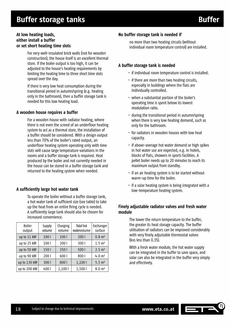
A suffi ciently large hot water tank
To operate the boiler without a buffer storage tank, a hot water tank of suffi cient size (see table) to take up the heat from an entire fi ring cycle is needed. A suffi ciently large tank should also be chosen for increased convenience.
Boiler output
Supply volume
Charging volume
Total hot watervolume
Exchanger surface
up to 11 kW 100 l 100 l 200 l 0.8 m²
up to 25 kW 100 l 200 l 300 l 1.5 m²
up to 50 kW 150 l 350 l 500 l 2.5 m²
up to 90 kW 200 l 600 l 800 l 4.0 m²
up to 130 kW 300 l 800 l 1,100 l 5.5 m²
up to 200 kW 400 l 1,100 l 1,500 l 8.0 m²
No buffer storage tank is needed if
no more than two heating circuits (without individual room temperature control) are installed.
A buffer storage tank is needed
• if individual room temperature control is installed.
• if there are more than two heating circuits, especially in buildings where the flats are individually controlled.
• when a substantial portion of the boiler's operating time is spent below its lowest modulation ratio.
• during the transitional period in autumn/spring when there is very low heating demand, such as only for the bathroom.
• for radiators in wooden houses with low heat capacity.
• if above-average hot water demand or high spikes in hot water use are expected, e.g. in hotels, blocks of flats, showers in sports facilities. A pellet boiler needs up to 20 minutes to reach its maximum output from standby.
• if an air heating system is to be started without warm-up time for the boiler.
• if a solar heating system is being integrated with a low-temperature heating system.
Finely adjustable radiator valves and fresh water module
The lower the return temperature to the buffer, the greater its heat storage capacity. The buffer utilisation of radiators can be improved considerably with very fi nely adjustable thermostat valves (kvs less than 0.35).
With a fresh water module, the hot water supply can be integrated in the buffer to save space, and solar can also be integrated in the buffer very simply and effectively.
19PE-K installation 35 to 90 kW 2012-02
Buffer Buffer storage tanks
Buffers for multi-boiler systems
For systems with several boilers and also for those with several very different heating circuits (especially different times of operation or air and underfl oor heating in the same heating system), a bypass is needed between heat producers and consumers to ensure stable hydraulic conditions for the individual circuits. A bypass is nothing more than a pipe connection between supply and return, having the same diameter as the supply and return themselves. The differential water quantities from heating and boiler circuits fl ow through this bypass, resulting in a neutral pressure point that ensures that the heating circulation cannot infl uence the boiler water circulation and vice versa.
A bypass that can do more than just stabilise pressure conditions is the buffer. If a wood boiler for the base-load range and an oil/gas boiler for peak load/emergency reserve are operated together in a heating system, a buffer storage tank reduces the operating time of the peak-load boiler by compensating for brief differences between production and consumption. The number of boiler starts/stops when consumption fl uctuates around the rated load of a boiler is reduced, saving energy and easing stress on the boiler.
To work as an output compensator and bypass for several boilers, the buffer's storage capacity should be chosen to match 20 to 30 minutes of full-load operation for the largest automatic wood boiler in the system. In special cases, peak loads and noncontinuously operated air heating systems must also be taken into account, or the morning peak if the start of an oil/gas boiler is to be avoided. The morning peaks themselves should be minimised with staggered starting times for the heating circuits as well as reasonable set-back temperatures.
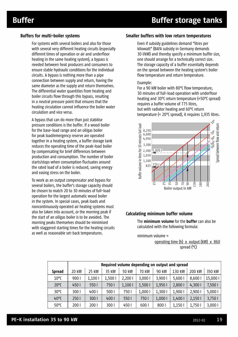
Smaller buffers with low return temperatures
Even if subsidy guidelines demand "litres per kilowatt" (BAFA subsidy in Germany demands 30 l/kW) and thereby specify a minimum buffer size, one should arrange for a technically correct size. The storage capacity of a buffer essentially depends on the spread between the heating system's boiler fl ow temperature and return temperature.
Example: For a 90 kW boiler with 80°C fl ow temperature, 30 minutes of full-load operation with underfl oor heating and 30°C return temperature (=50°C spread) requires a buffer volume of 775 litres, but with radiator heating and 60°C return temperature (= 20°C spread), it requires 1,935 litres.
10°
50°40°30°20°
Sprea
d betw
een
flow
and r
eturn
15 260
180
1309070503525
Boiler output in kW
825
1,100
1,650
3,300
4,9506,6008,250
2,200
Buffe
r vol
ume i
n lit
res f
or 3
0 m
inut
es fu
ll lo
ad
1,935 l
775 l
Required volume depending on output and spread
Spread 20 kW 25 kW 35 kW 50 kW 70 kW 90 kW 130 kW 200 kW 350 kW
10°C 900 l 1,100 l 1,500 l 2,200 l 3,000 l 3,900 l 5,600 l 8,600 l 15,000 l
20°C 450 l 550 l 750 l 1,100 l 1,500 l 1,950 l 2,800 l 4,300 l 7,500 l
30°C 300 l 400 l 500 l 750 l 1,000 l 1,300 l 1,900 l 2,900 l 5,000 l
40°C 250 l 300 l 400 l 550 l 750 l 1,000 l 1,400 l 2,150 l 3,750 l
50°C 200 l 200 l 300 l 450 l 600 l 800 l 1,150 l 1,750 l 3,000 l
Calculating minimum buffer volume
The minimum volume for the buffer can also be calculated with the following formula:
minimum volume =
operating time (h) x output (kW) x 860
spread (°C)

20 www.eta.co.atSubject to change due to technical improvements
Hydraulic integration Buffer
Hydraulic integration
ETA stratified buffer SP
Upper buffer sensor
Lower buffer sensor
Wood chip/pellet boiler flowHeating circuits flowHot water tank flow
Oil/gas boiler flow
Wood chip/pellet boiler returnHeating circuits return
Oil/gas boiler return
With conventional hot water supply
ETA stratified buffer SP
Upper buffer sensor
Lower buffer sensor
Wood chip/pellet boiler flowHeating circuits flow
Oil/gas boiler flow
Wood chip/pellet boiler returnHeating circuits return
Oil/gas boiler return
With fresh water module
Hot water tank return
Cold waterHot water
Upper buffer sensor for hot water
ETA stratified buffer Solar SPS
With solar exchanger and fresh water module
ETA stratified buffer SP
Upper buffer sensor
Lower buffer sensor
Wood chip/pellet boiler flowHeating circuits flow
Oil/gas boiler flow
Oil/gas boiler return
With stratified charging module and fresh water module
Cold waterHot water
Upper buffer sensor for hot water Upper buffer sensor
Lower buffer sensor
Wood chip/pellet boiler flowHeating circuits flow
Oil/gas boiler flow
Oil/gas boiler return
Cold waterHot water
Upper buffer sensor for hot water
Low-temperature circuits return
High-temperature circuits return
Buffer top solar
Solar flowSolar return
Solar flow
Solar return
Lower buffer sensor Low-temperature circuits return
High-temperature circuits returnBuffer bottom solar
Wood chip/pellet boiler return Wood chip/pellet boiler return
For the largest possible buffer storage capacity and for maximum solar yield even in winter, low return temperatures are the goal.
The best stratified buffer can't unmix what has been mixed by heat distributors. Especially in houses where radiators and underfloor circuits are present, no mixing heat distributors should be installed; the returns should be connected directly to the buffer.
An underfloor heating system can still be operated with the return from radiators.
If a solar heating system is connected, only the cold returns from an underfloor heating system or from a fresh water module may be fed into the solar-heated lower third of the buffer. This results in lower solar panel working temperatures with significantly higher efficiencies and also significantly higher solar yield.
An oil or gas boiler should always be connected only through the upper quarter of the buffer.
Siphon loops downwards at all connections reduce heat losses in summer.
21PE-K installation 35 to 90 kW 2012-02
Buffer Hydraulic integration of several buffers
Hydraulic integration of several buffers
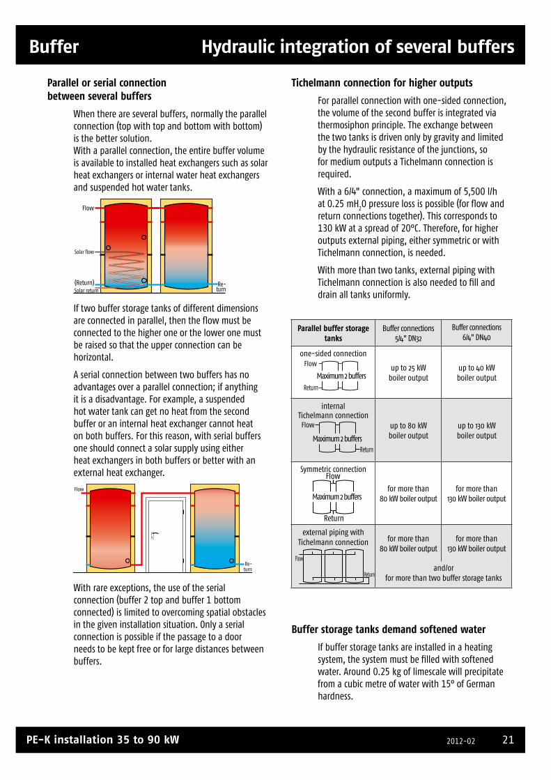
Parallel or serial connection between several buffers
When there are several buffers, normally the parallel connection (top with top and bottom with bottom) is the better solution.With a parallel connection, the entire buffer volume is available to installed heat exchangers such as solar heat exchangers or internal water heat exchangers and suspended hot water tanks.
(Return)
Flow
Solar return Re-turn
Solar flow
If two buffer storage tanks of different dimensions are connected in parallel, then the fl ow must be connected to the higher one or the lower one must be raised so that the upper connection can be horizontal.
A serial connection between two buffers has no advantages over a parallel connection; if anything it is a disadvantage. For example, a suspended hot water tank can get no heat from the second buffer or an internal heat exchanger cannot heat on both buffers. For this reason, with serial buffers one should connect a solar supply using either heat exchangers in both buffers or better with an external heat exchanger.
Re-turn
Flow
With rare exceptions, the use of the serial connection (buffer 2 top and buffer 1 bottom connected) is limited to overcoming spatial obstacles in the given installation situation. Only a serial connection is possible if the passage to a door needs to be kept free or for large distances between buffers.
Tichelmann connection for higher outputs
For parallel connection with one-sided connection, the volume of the second buffer is integrated via thermosiphon principle. The exchange between the two tanks is driven only by gravity and limited by the hydraulic resistance of the junctions, so for medium outputs a Tichelmann connection is required.
With a 6/4" connection, a maximum of 5,500 l/h at 0.25 mH
2O pressure loss is possible (for fl ow and
return connections together). This corresponds to 130 kW at a spread of 20°C. Therefore, for higher outputs external piping, either symmetric or with Tichelmann connection, is needed.
With more than two tanks, external piping with Tichelmann connection is also needed to fi ll and drain all tanks uniformly.
Buffer storage tanks demand softened water
If buffer storage tanks are installed in a heating system, the system must be fi lled with softened water. Around 0.25 kg of limescale will precipitate from a cubic metre of water with 15° of German hardness.
Parallel buffer storage tanks
Buffer connections 5/4" DN32
Buffer connections 6/4" DN40
one-sided connection
up to 25 kW boiler output
up to 40 kW boiler output
internal Tichelmann connection
up to 80 kW boiler output
up to 130 kW boiler output
Symmetric connection
for more than 80 kW boiler output
for more than 130 kW boiler output
external piping with Tichelmann connection for more than
80 kW boiler outputfor more than
130 kW boiler output
and/or for more than two buffer storage tanks
Flow
Return
Flow
Return
Flow
Return
Maximum 2 buffers
Maximum 2 buffers
Flow
Return
Maximum 2 buffers
22 www.eta.co.atSubject to change due to technical improvements
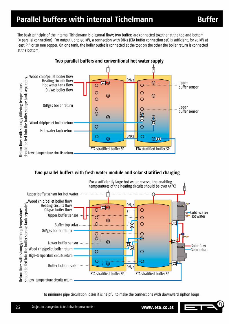
Parallel buffers with internal Tichelmann Buffer
Parallel buffers with internal Tichelmann
Cold water Hot water
Solar flow Solar return
Wood chip/pellet boiler return
DN32
DN32
ETA stratified buffer SP ETA stratified buffer SP
Upperbuffer sensor
Upperbuffer sensor
Wood chip/pellet boiler flowHeating circuits flowHot water tank flow
Oil/gas boiler flow
Hot water tank return
Low-temperature circuits return
Oil/gas boiler return
For a sufficiently large hot water reserve, the enabling temperatures of the heating circuits should be over 45°C!
Retu
rn li
nes w
ith st
rong
ly d
iffer
ing
tem
pera
ture
s sh
ould
be
fed
into
the
buffe
r sto
rage
tank
sepa
rate
ly.
To minimise pipe circulation losses it is helpful to make the connections with downward siphon loops.
DN32
DN32
ETA stratified buffer SP ETA stratified buffer SP
Upper buffer sensor
Lower buffer sensor
Buffer bottom solar
Wood chip/pellet boiler flowHeating circuits flow
Oil/gas boiler flow
High-temperature circuits return
Low-temperature circuits return
Oil/gas boiler return
Retu
rn li
nes w
ith st
rong
ly d
iffer
ing
tem
pera
ture
s sh
ould
be
fed
into
the
buffe
r sto
rage
tank
sepa
rate
ly
Two parallel buffers and conventional hot water supply
Two parallel buffers with fresh water module and solar stratified charging
Buffer top solar
Upper buffer sensor for hot water
Wood chip/pellet boiler return
The basic principle of the internal Tichelmann is diagonal flow; two buffers are connected together at the top and bottom (= parallel connection). For output up to 90 kW, a connection with DN32 (ETA buffer connection set) is sufficient, for 30 kW at least R1” or 28 mm copper. On one tank, the boiler outlet is connected at the top; on the other the boiler return is connected at the bottom.
23PE-K installation 35 to 90 kW 2012-02
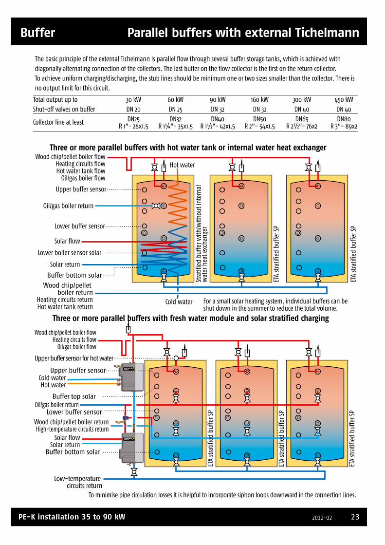
Buffer Parallel buffers with external Tichelmann
Parallel buffers with external Tichelmann
Wood chip/pellet boiler returnHigh-temperature circuits return
Stra
tifie
d bu
ffer w
ith/w
ithou
t int
erna
l w
ater
hea
t exc
hang
erET
A st
ratif
ied
buffe
r SP
ETA
stra
tifie
d bu
ffer S
P
ETA
stra
tifie
d bu
ffer S
PET
A st
ratif
ied
buffe
r SP
ETA
stra
tifie
d bu
ffer S
P
Low-temperature circuits return
Upper buffer sensor
Lower buffer sensor
Buffer bottom solar
Upper buffer sensor for hot water
Buffer top solar
Total output up to Shut-off valves on buffer
Collector line at least
30 kWDN 20DN25
R 1“- 28x1.5
300 kWDN 40DN65
R 2½“- 76x2
160 kWDN 32DN50
R 2“- 54x1.5
90 kWDN 32DN40
R 1½“- 42x1.5
60 kWDN 25DN32
R 1¼“- 35x1.5
450 kWDN 40DN80
R 3“- 89x2
To minimise pipe circulation losses it is helpful to incorporate siphon loops downward in the connection lines.
Three or more parallel buffers with hot water tank or internal water heat exchanger
Three or more parallel buffers with fresh water module and solar stratified charging
Wood chip/pellet boiler flowHeating circuits flowHot water tank flow
Oil/gas boiler flow
Wood chip/pellet boiler return
Heating circuits returnHot water tank return
Oil/gas boiler return
Upper buffer sensor
Lower buffer sensor
Buffer bottom solar
Wood chip/pellet boiler flowHeating circuits flow
Oil/gas boiler flow
Cold waterHot water
Solar flowSolar return
Oil/gas boiler return
Cold water
Hot water
Lower boiler sensor solar
Solar flow
Solar return
For a small solar heating system, individual buffers can be shut down in the summer to reduce the total volume.
The basic principle of the external Tichelmann is parallel flow through several buffer storage tanks, which is achieved with diagonally alternating connection of the collectors. The last buffer on the flow collector is the first on the return collector. To achieve uniform charging/discharging, the stub lines should be minimum one or two sizes smaller than the collector. There is no output limit for this circuit.
24 www.eta.co.atSubject to change due to technical improvements
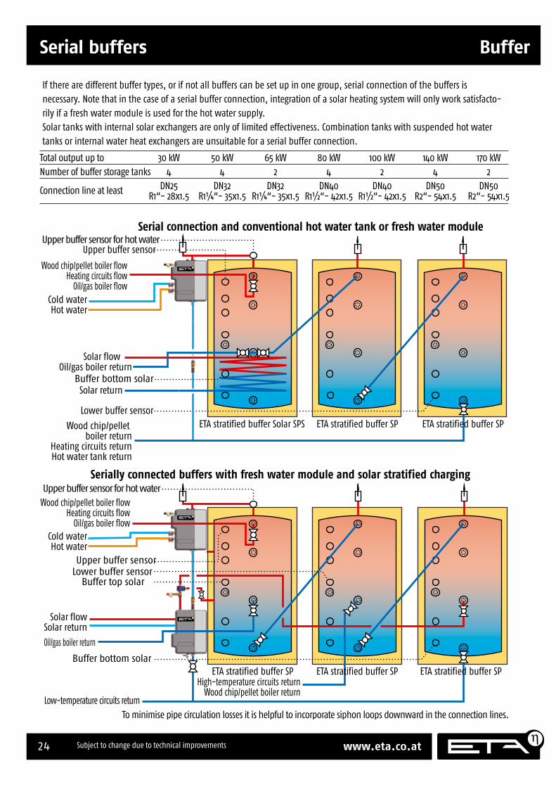
Serial buffers Buffer
Serial buffers
Solar flow
Solar return
High-temperature circuits returnWood chip/pellet boiler return
ETA stratified buffer SP
Low-temperature circuits return
Upper buffer sensorLower buffer sensor
Buffer bottom solar
Upper buffer sensor for hot water
Buffer top solar
Total output up to Number of buffer storage tanks
Connection line at least
30 kW4
DN25R1“- 28x1.5
140 kW4
DN50R2“- 54x1.5
100 kW2
DN40R1½“- 42x1.5
80 kW4
DN40R1½“- 42x1.5
170 kW2
DN50R2“- 54x1.5
50 kW4
DN32R1¼“- 35x1.5
To minimise pipe circulation losses it is helpful to incorporate siphon loops downward in the connection lines.
Serial connection and conventional hot water tank or fresh water module
Serially connected buffers with fresh water module and solar stratified charging
Wood chip/pellet boiler flowHeating circuits flow
Oil/gas boiler flow
Wood chip/pellet boiler return
Heating circuits returnHot water tank return
Oil/gas boiler return
Upper buffer sensor
Lower buffer sensor
Wood chip/pellet boiler flowHeating circuits flow
Oil/gas boiler flowCold waterHot water
Solar flowSolar return
Oil/gas boiler return
65 kW2
DN32R1¼“- 35x1.5
ETA stratified buffer SP ETA stratified buffer SP
ETA stratified buffer SP ETA stratified buffer Solar SPS ETA stratified buffer SP
Cold waterHot water
Buffer bottom solar
Upper buffer sensor for hot water
If there are different buffer types, or if not all buffers can be set up in one group, serial connection of the buffers is necessary. Note that in the case of a serial buffer connection, integration of a solar heating system will only work satisfacto-rily if a fresh water module is used for the hot water supply. Solar tanks with internal solar exchangers are only of limited effectiveness. Combination tanks with suspended hot water tanks or internal water heat exchangers are unsuitable for a serial buffer connection.

25PE-K installation 35 to 90 kW 2012-02

26 www.eta.co.atSubject to change due to technical improvements
Minimum clearances for maintenance Installation
Installation
Minimum clearances for maintenance
Position boiler in boiler room
Position the boiler in the boiler room while complying with the minimum clearances for main-tenance and installation.
If soundproofing is needed, place the optionally available sound insulation strips under the boiler.
Level boiler
After positioning the boiler, level it on the floor.
For soundproofing, use the load distribution plates from the sound insulation set for height adjust-ment. For strongly inclined floors, divide the load distribution plates into halves or thirds.
Minimum clearances for maintenance for PE-K
The adjacent sketch shows the space requirements and clearances for maintenance and installation of the boiler. at least 400 mm
610 mm(710 mm)
at least 300 mm
at least 400 mm
Dimensions in parentheses apply for 70 and 90 kW
1100
mm
(124
9 m
m)
at le
ast 8
00 m
m(9
50 m
m)
PE-K35 - 90 kW
The dimensions in parentheses apply for 70 and 90 kW boilers.
The sketch shows a boiler with right-hand tundish; for a left-hand tundish a mirror image applies.
27PE-K installation 35 to 90 kW 2012-02
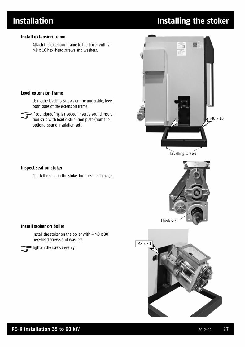
Installation Installing the stoker
Installing the stoker
Install extension frame
Attach the extension frame to the boiler with 2 M8 x 16 hex-head screws and washers.
Level extension frame
Using the levelling screws on the underside, level both sides of the extension frame.
If soundproofing is needed, insert a sound insula-tion strip with load distribution plate (from the optional sound insulation set).
Inspect seal on stoker
Check the seal on the stoker for possible damage.
Install stoker on boiler
Install the stoker on the boiler with 4 M8 x 30 hex-head screws and washers.
Tighten the screws evenly.
Check seal
M8 x 16
Levelling screws
M8 x 30

28 www.eta.co.atSubject to change due to technical improvements
Attaching the pellet bin Installation
Check freedom of movement of stoker screw
In the combustion chamber, check the stoker screw's clearance (1 - 2 mm) from the bottom of the stoker channel.
The stoker screw may not contact the channel bottom.
Install pellet bin on stoker
Attach the pellet bin to the stoker with 4 M5 x 20 hex-head screws and 2 washers each.
Install struts on pellet bin
Install both struts to support the pellet bin; attach them to the extension frame and the pellet bin using 2 M8 x 16 hex-head screws and washers for each.
Adjust pellet bin
Adjust for uniform spacing between pellet bin and boiler to prevent contact with the casing later.
Screw
Channel base
Attaching the pellet bin
M5 x 20
M8 x 16
Struts
29PE-K installation 35 to 90 kW 2012-02
Installation Flue gas recirculation
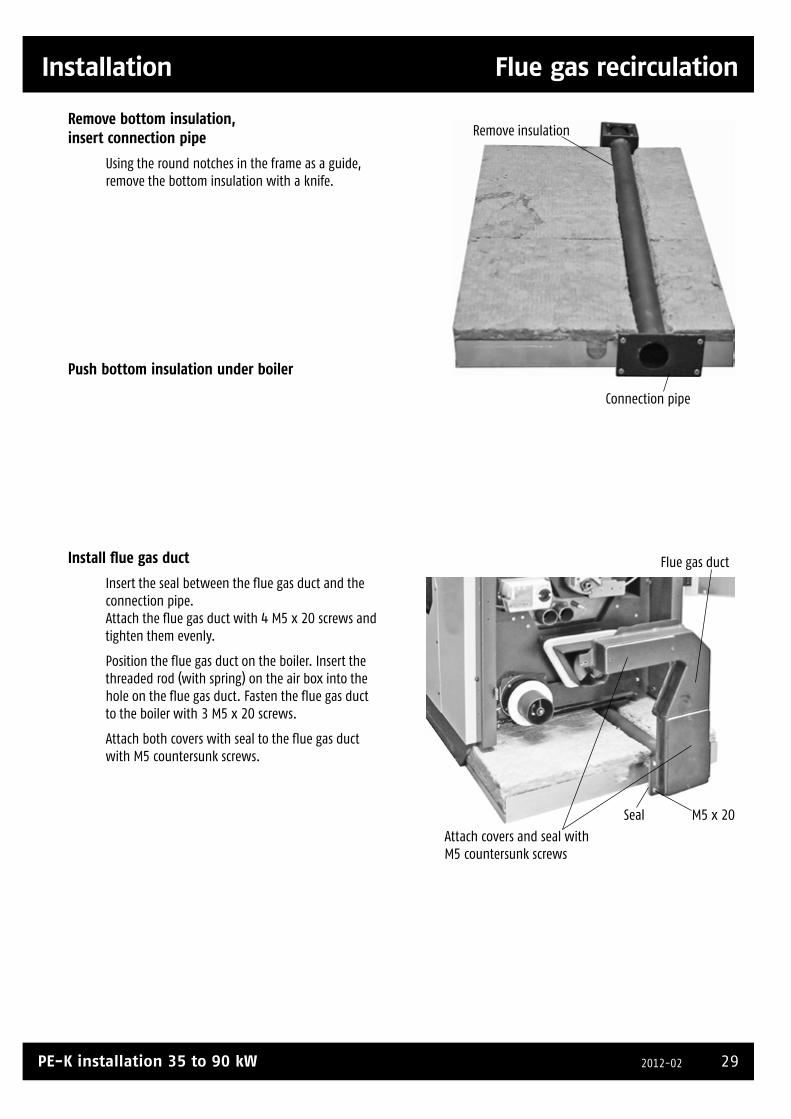
Remove bottom insulation, insert connection pipe
Using the round notches in the frame as a guide, remove the bottom insulation with a knife.
Push bottom insulation under boiler
Install flue gas duct
Insert the seal between the flue gas duct and the connection pipe. Attach the flue gas duct with 4 M5 x 20 screws and tighten them evenly.
Position the flue gas duct on the boiler. Insert the threaded rod (with spring) on the air box into the hole on the flue gas duct. Fasten the flue gas duct to the boiler with 3 M5 x 20 screws.
Attach both covers with seal to the flue gas duct with M5 countersunk screws.
Remove insulation
Connection pipe
Seal M5 x 20
Flue gas duct
Attach covers and seal with M5 countersunk screws
Flue gas recirculation

30 www.eta.co.atSubject to change due to technical improvements
Attaching the pellet bin Installation
Install flue pipe
Install the flue pipe on the rear side of the boiler.
Insert a seal into each of the connecting flanges at the top and bottom.
Fasten the flue pipe with M5 x 15 hex-head screws.
Flue pipe
Insert seal
Cleaning cover and seal
M5 x 15
M5 x 15
Insert seal
M5 x 15

31PE-K installation 35 to 90 kW 2012-02
Installation Attaching the pellet bin
Attach cover, do not block flue gas recirculation
The flue gas recirculation on PE-K boilers may never be blocked.
Attach the cover (with a seal) to the flue outlet using 2 wing screws.
Attach insulation to flue pipe
Attach the insulation to the flue pipe.
Insert ignition fan
Insert the ignition fan into the opening beside the stoker and attach the spring to the casing.
Do not block Cover Seal
Attach insulation
Ignition fan

32 www.eta.co.atSubject to change due to technical improvements
Connecting cables Installation
Remove panel from top of boiler
Remove the panel from the top of the boiler and remove the cable duct covers.
Cables for vacuum motor, level sensor
Feed the cables for the vacuum motor and level sensor downward between the pellet bin and the boiler. Then use the included cable to extend the level sensor cable.
Feed both cables through the opening in the extension frame and over the cable ducts on the rear side of the boiler to the boiler's circuit board.
Cables for ignition fan and stoker
Connect the stoker cable and feed it together with the ignition fan cable through the opening in the extension frame over the cable ducts to the boiler's circuit board.
Extend the ignition fan cable in the cable duct on the rear side of the boiler.
Connect cables
Connect the cables to the circuit board. See the circuit diagram on page 38.
If you want to operate the boiler remotely via Internet (www.meinETA.at), extend the network cable out of the boiler with a suitable extension.
Feed all cables through opening
Feed cables downward
Connecting cables

33PE-K installation 35 to 90 kW 2012-02
Installation Attach pellet hoses
Expose earthing wire on pellet hose
Expose approx. 5 cm of earthing wire at both ends of the pellet hoses (suction hose, return air hose).
This allows the formation of an earth connection from the boiler to the discharge conveyor when connecting the pellet hoses, preventing electrostatic charge build-up.
Fasten pellet hoses to pellet bin and earth them
Connect the pellet hoses to the connectors on the pellet bin with hose clamps (from basic set for screw conveyor).
Moisten the connectors with water if it is difficult to fit the hoses over them (do not use grease).
Connect the earthing wire of both pellet hoses to the yellow-green earthing cable.
Connect pellet hoses to discharge conveyor in store and earth them
Expose approx. 5 cm of earthing wire at both ends of the pellet hoses (suction hose, return air hose) and bend it into the hoses.
The earthing wire must have good contact with the nozzles on the discharge conveyor, so file away paint/coating from the nozzle.
Slip the pellet hoses with hose clamps onto the nozzles. Looking towards the storeroom at the connection head, attach the return air hose on the left and the pellet hose on the right.
Moisten the nozzles with water if it is difficult to fit the hoses over them (do not use grease).
Tighten the hose clamps on both pellet hoses.Back air Suction nozzle
Expose earthing wire
Attach pellet hoses
Back air
Suction
34 www.eta.co.atSubject to change due to technical improvements
Attaching housing/panels Installation
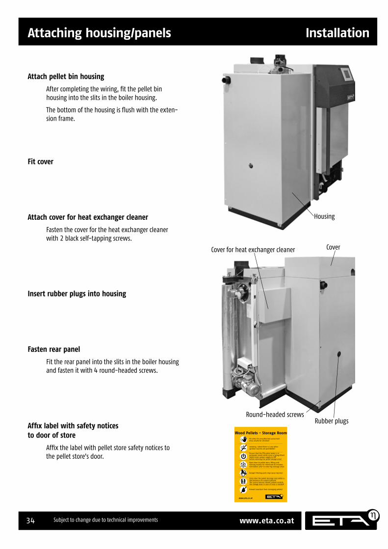
Attach pellet bin housing
After completing the wiring, fit the pellet bin housing into the slits in the boiler housing.
The bottom of the housing is flush with the exten-sion frame.
Fit cover
Attach cover for heat exchanger cleaner
Fasten the cover for the heat exchanger cleaner with 2 black self-tapping screws.
Insert rubber plugs into housing
Fasten rear panel
Fit the rear panel into the slits in the boiler housing and fasten it with 4 round-headed screws.
Affix label with safety notices to door of store
Affix the label with pellet store safety notices to the pellet store's door.
Housing
Round-headed screws
Cover for heat exchanger cleaner Cover
Rubber plugs
Attaching housing/panels
Prevent moisture from damaging pellets!
Danger! Moving parts may cause injuries!
Open door to pellet store, filling andventing nozzles for minimum 60 minutesventilation prior to entering storeage area!
Ensure that the ETA pellet boiler is inautomatic mode while store is being filled!Switch main power supply to OFFbefore entering the pellet storage area!
Smoking, naked flame or any otherignition sources are prohibited!
No entry for unauthorized personnel!Area unsafe for children!
www.eta.co.at
Wood Pellets - Storage Room
Only enter the pellet storeage area while inthe presence of a second person!The second person should remain outsidethe storage area in case of help is needed!
35PE-K installation 35 to 90 kW 2012-02
Installation Installing the ash box
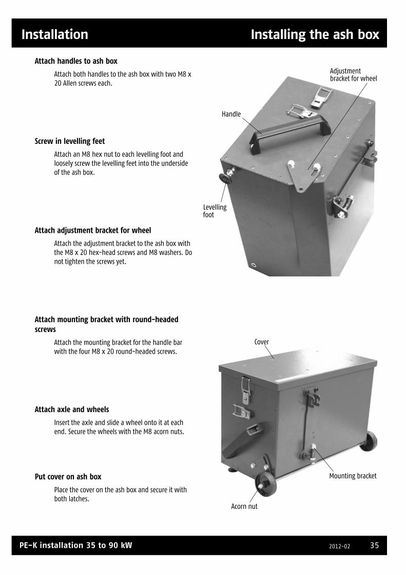
Attach handles to ash box
Attach both handles to the ash box with two M8 x 20 Allen screws each.
Screw in levelling feet
Attach an M8 hex nut to each levelling foot and loosely screw the levelling feet into the underside of the ash box.
Attach adjustment bracket for wheel
Attach the adjustment bracket to the ash box with the M8 x 20 hex-head screws and M8 washers. Do not tighten the screws yet.
Attach mounting bracket with round-headed screws
Attach the mounting bracket for the handle bar with the four M8 x 20 round-headed screws.
Attach axle and wheels
Insert the axle and slide a wheel onto it at each end. Secure the wheels with the M8 acorn nuts.
Put cover on ash box
Place the cover on the ash box and secure it with both latches.
Handle
Levelling foot
Adjustment bracket for wheel
Acorn nut
Cover
Mounting bracket
Installing the ash box

36 www.eta.co.atSubject to change due to technical improvements
Attaching housing/panels Installation
Install ash box on boiler
Install the ash box on the boiler and secure it with the side latches.
Adjust height of ash box
Use the adjustable bracket and the levelling feet to adjust the height of the ash box.
Attach clamps for handle bar
If desired, the handle bar can be attached to the side panel with the supplied clamps.
Attach both clamps to the side panel with the 4.2 x 16 self-tapping screws. Position them so that the end of the handle bar is in contact with the fl oor.
Mount handle bar on ash box
Slip the handle bar into the mounting bracket on the ash box and fi x it in place.
Now you can easily move the ash box to empty it.
Adjust height with bracket and levelling feet
Attach clamps for handle bar if desired
~5 cm

37PE-K installation 35 to 90 kW 2012-02

38 www.eta.co.atSubject to change due to technical improvements
Terminal diagram
Terminal diagram
Mains protection: C13
Mains connection: 3 x 1.5²
Cable type: HO5VV-F
230 V AC devices: 1.0²
Temperature sensors: 0.5² to 1.0²
Power for direct connection
per pump output: 250 W maximum
all pumps together: 700 W maximum
Use only flexible cable with the specified cross-sections! (otherwise no warranty for the electronics)
Depending on the configuration, the sensor input T8 is available for "hot water tank bottom" or for the "primary return" temperature for a fresh water module.
** configuration-dependent

39PE-K installation 35 to 90 kW 2012-02
Terminal diagram
The network cable for remote operation via Internet is connected to the touchscreen; see page 41.

40 www.eta.co.atSubject to change due to technical improvements
Requirements Remote control
Remote control
Requirements
Using remote control
With remote control, you can control your ETA boiler over long distances via the Internet with a PC, smartphone or tablet (pad), just as if your were standing in front of the boiler's touch screen.
For example, if you are away from home for a long time, you can verify that the heating is switched off. You can also switch it back on before you return.
The ETA boiler's touch screen is connected to the Internet. Once you have registered your touch screen, you can log in to the ETA homepage <www.meinETA.at> using your access details.
You can access this homepage via a PC with an Internet connection or a smartphone or tablet with Internet capabilities. You can view the touch screen at <www.meinETA.at> and control your boiler remotely.
Creating a partner network
The "Partner Network" function allows you to assign access rights to other users via the home-page <www.meinETA.at>. This gives multiple users access to your boiler touch screen.
Example: An installer can access customer touch screen controls via <www.meinETA.at>. In order to allow this, the customers simply need to authorise the installer's access (see page 20 onward).
Data transfers, downloading and fl at rates
As soon as remote control has been activated, the touch screen automatically connects to the Internet. The current status of the Internet connection is indicated by an icon at the bottom of the screen.
The data is transmitted via the Internet, adding to the amount of data you download via your connection. In order to avoid excessive costs, we recommend that you use a fl at rate or a contract with no data download limit for your Internet connection.
Boiler with touch screen and software version 1.18.0 or higher
In order to use the remote control function, your boiler must be equipped with an ETAtouch control system (touch screen). The software installed on the boiler must be version 1.18.0 or higher. If this is not the case, the software must be updated.
Internet connection
In order to establish an Internet connection to your boiler, the touch screen must be connected to the Internet. To do this, the house must have a broadband Internet connection. The connection can be established via:
• a network cable from your modem to the touch screen
or
• the ETA FreeLine wireless connection
Browser for remote control
You can connect your PC, smartphone or tablet to the boiler via <www.meinETA.at>. In order to do this, you must have a browser that supports HTML 5, e.g.:
• Mozilla Firefox
• Apple Safari
• Google Chrome
• Microsoft Internet Explorer version 9 or higher
• some default Android browsers 2.2 or higher
Internet connection via smartphone or tablet
In order to use the remote control function from your smartphone or tablet (pad), your device must use either Android or iOS (Apple) as its operating system. Your network operator's Internet service must provide at least "EDGE"-level service ("3G" recommended).
Requirements

41PE-K installation 35 to 90 kW 2012-02
Remote control Login data, network cable
Login data, network cable
Requesting login data
You can request login data for using remote control at <www.meinETA.at>. Each account is registered to a person, not to the boiler.
Press the [Create account] button and enter the required information in the corresponding fi elds.
Once you have entered all the data, press [Send]. Your details will be sent to ETA, and your personal login data (username and password) will be sent to the specifi ed e-mail address.
You can still change your personal data after you have registered. It is recommended that you change your password to a personal combination that you will be able to remember.
Checking your Internet connection
In order to allow remote control of your boiler via <www.meinETA.at>, the touch screen of your boiler must be connected to the Internet. This connection can be made via a network cable or a wireless connection, e.g. ETA FreeLine.
Before connecting the touch screen to the network, it is a good idea to use a laptop to check that the Internet connection is working, To do this, plug the cable into your laptop and test whether you can access the Internet using this LAN connection.
Connecting the network cable to the touch screen
On PU and PC boilers, remove the upper casing. You do not need to remove the front of the boiler unless you are inserting the cable via the tube running from the base of the boiler.
Plug the network cable into the port at the bottom left-hand corner of the touch screen (under the casing).
Port for network cable
On PE-K and HACK 20 to 130 boilers, remove the upper boiler casing. The cable duct in the electronics board houses the end of a patch cable that protrudes from the door. A patch extension cable (male/female) is required to extend this connection.
On the HACK 200, the end of the patch cable is located in the control box on the side of the boiler.
Controlling the touch screen in a control extension (wall housing) by remote control?
If the control extension is connected to the boiler via a CAN bus, a separate Internet connection is not required. A separate Internet connection is required if you have an "island" control system that is not connected to the boiler.
Confi guration
Login data, network cable

42 www.eta.co.atSubject to change due to technical improvements
Network settings Remote control
Network settings
Checking the network settings
The network settings must be checked in order to ensure that the touch screen can be controlled remotely via <www.meinETA.at>. "Service" level access is required to do this.
The network settings must be checked on every touch screen that is intended for use by remote control.
Make sure that the Internet connection network cable is connected to the touch screen and that the Internet connection is active.
Checking the network settings
Using "Service" level access, go to the toolbox by pressing .
Press the [Network Settings] button.
Network settings
A screen opens:
Select [Automatic confi guration (DHCP)], then press [Accept].
Once this option has been activated, the system will check the network settings after it has restarted and confi gure them automatically.
Restarting the boiler using the main switch
A message appears indicating that the changes will not be applied until the next time the unit is restarted.
Press [OK] and switch off the boiler at the main switch. Wait for about 10 seconds, then switch it back on again.
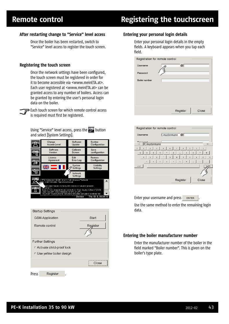
43PE-K installation 35 to 90 kW 2012-02
Remote control Registering the touchscreen
Registering the touchscreen
Entering your personal login details
Enter your personal login details in the empty fi elds. A keyboard appears when you tap each fi eld.
t.mustermann
t.mustermann
Enter your username and press .
Use the same method to enter the remaining login data.
Entering the boiler manufacturer number
Enter the manufacturer number of the boiler in the fi eld marked "Boiler number". This is given on the boiler's type plate.
After restarting change to "Service" level access
Once the boiler has been restarted, switch to "Service" level access to register the touch screen.
Registering the touch screen
Once the network settings have been confi gured, the touch screen must be registered in order for it to become accessible via <www.meinETA.at>. Each user registered at <www.meinETA.at> can be granted access to any number of boilers. Access can be granted by entering the user's personal login data on the boiler.
Each touch screen for which remote control access is required must fi rst be registered.
Using "Service" level access, press the button and select [System Settings].
Press .
Registering the touch screen

44 www.eta.co.atSubject to change due to technical improvements
Registering the touchscreen Remote control
Registering the touchscreen
Once you have entered all your login data, press to save the data.
t.mustermann t-online.at
my...
xxxx-yyyyy-zzzzz
Registering the touch screen
Once you have pressed the button, the touch screen is registered at <www.meinETA.at>.
The symbol appears at the bottom of the screen while the system is establishing an Internet connection.
If the system is unable to establish an Internet connection, check that the login data you have provided is correct.
Internet connection status
After a delay of about 15 seconds, the screen displays the current status of the Internet connection.
Connecting
This symbol is displayed while the touch screen is establishing an Internet connection, during registration or after remote control has been switched on.
Connected
The touch screen has an active Internet connection to the homepage <www.meinETA.at>. The boiler can be controlled remotely.
No connection possible
The touch screen is not currently connected to the Internet. If this symbol is still being displayed after one minute, there is a fault in the access cable, with your Internet service provider or with the meinETA server.
In order to locate the fault, it may help to test the network connection by connecting a laptop to the network instead of the boiler.

45PE-K installation 35 to 90 kW 2012-02
Pellet store Delivery, storage room, boiler room
Pellet store
Delivery, storage room, boiler room
Delivery of pellets
The pellets are delivered with a tank truck and blown into the storage room. The tank trucks usually have a pump hose with a length of up to 30 m. If you expect to need a longer pump hose, consult your pellet supplier regarding their technical capabilities.
Vehicle access should be at least 3 m wide and 4 m high. The truck can only back up if the street and gate are wide enough.
Check function before fi lling for the fi rst time!
Before fi lling the pellet store, test the functionality of the entire heating system and the pellet conveying system. For this purpose, deposit some pellets (bagged product) in the storage room near the discharge screw.
Only fi ll up the pellet store after this test has been completed successfully. Noises result when the conveyor is empty; they go away after fi lling.
Position of pellet store and boiler room
If possible, the pellet store should adjoin an outer wall since the fi lling nozzle should be accessible from outside. For an interior storage room, the blower and return air pipes should be extended to the outer wall.
Position of boiler room
The boiler room should also adjoin an outer wall to ensure direct supply of combustion air to the pellet boiler. For interior boiler rooms, an air supply channel must lead from the boiler room to the outer wall.
Screw or suction discharge conveyor?
In general, discharge conveyors with screws are preferable since they can completely empty the storage room. Screw discharge conveyors are available up to a maximum length of 5.0 m in steps of 0.5 m.
For a discharge conveyor with suction heads, the optimum length of the storage room is 3 m. A greater length would result in too much unusable storage space between the suction heads. With a switch unit, up to 3 suction heads can be installed.
Blower coupling
Pellet store
Boiler room
Filling hose, 30 m maximum length
Tank truck
Boile
r
Return air coupling

46 www.eta.co.atSubject to change due to technical improvements
Discharge conveyor with screw Pellet store
Discharge conveyor with screw
Open feeder screws with 1,000 mm, 1,500 mm and 2,000 mm, can be combined for total length up to 5,000 mm. Choose a screw length (open feeder) at least 100 mm shorter than the unobstructed room length (length can be up to 600 mm shorter)
End bearing pin (included in basic set)
Connection pin for connecting the screws (fi rst connection pin included in basic set; for each additional screw a pin is needed)
Flange plate with bearing (included in basic set)
Basic set for pellet discharge conveyor channel
Wall sheath
Maintenance cover
Drive motor
Screw end piece
Hose connection DN50 back air from boiler
Hose connection DN50 Pellets to boiler
Wall, 300 mm maximum
Hose connections
Maintenance cover with fireproof wadding
Modular discharge screw system Discharge conveyors with screws are preferable since they can completely empty the storage room. Screw discharge conveyors are available up to a maximum length of 5.0 m in steps of 0.5 m.
ETA PE
max. 5.00 m1.00 m 2.00 m2.00 m
1.20 m
at least 0.36 m0.66 m
max. 0.30 m
appr
ox. 0
.20 m
appro
x. 0.2
0 m
2 3 1 3
40°
at least 0.5 m
max. 6.50 m
0.5 m
Filling nozzle (centred, 2 nozzles offset in rooms wider than 3m)
27 mm formwork panels (smooth surface)
Wooden beams
No transfer of forces from tilted floor to walls with insufficient strength
Ventilation at least 200 cm²
Fireproof sleeve
Support frame
Pellet store
Panelling
Wooden beams
Empty space
Back air nozzle
Example for conveyor channel 2x2 m + 1x 1 m + 2x connection pin
Boiler room
Discharge screw
Impa
ct p
rote
ctio
n
Pellet store doorT30 with wooden panelling
Longitudinal section Cross section
320 x 250 mm wall opening
Suct
ion
and
back
air
hose
, 20
m o
r les
s
shee
t
Wal
l ope
ning
, he
ight
250
View against conveyor direction
25 H
eigh
t adj
usta
ble
+/-1
0
Wall opening, width 320

47PE-K installation 35 to 90 kW 2012-02
Pellet store Discharge conveyor with suction heads
Discharge conveyor with suction heads
Discharge conveyor with suction heads For discharge conveyors with suction heads, the optimum length of the storage room is 3 m. A greater length would result in too much unusable storage space between the suction heads. If a switch unit is used, up to 3 suction heads can be installed.
ETA PE
1.20 m ap
prox
. 0.20
m
appro
x. 0.20
m
2 3 1 3
40°
at least 0.5 m
0.5 m
at least 300 mm
Filling nozzle (centred, 2 nozzles offset in rooms wider than 3m)
27 mm formwork panels (smooth surface)
Wooden beams
No transfer of forces from support frame to walls with insufficient strength
Ventilation at least 200 cm²
Fireproof sleeve
Support frameMaximum length of pellet store 3m for optimum emptying
Pellet store
Back air nozzle
Boiler room
Suction heads
Impa
ct p
rote
ctio
n
Pellet store door T30 with wooden panelling
Longitudinal section Cross section
shee
t
at least 200 at least 320
at le
ast 1
50
Ø 220
Dimensions for installation of the switch unit
395 mm142 mm
268
mm
Fireproof door
Wooden boards
Z bracket
Back air nozzle
Filling nozzle
Switch unit
Mount suction heads on a board
0.3 m minimum
Impact protection sheet
Flexible hoses
Support frame of wooden beams
0.5 m
10 cm suction area
Pellet st
ore, 3 m maximum len
gth

48 www.eta.co.atSubject to change due to technical improvements
Demands on the storage room Pellet store
Demands on the storage room
Demands on the storage room
Static demands
The enclosing walls must withstand the load caused by the weight of the pellets (bulk weight 650 kg/m³).
The plasterwork should be durable enough that it cannot rub or fl ake off and contaminate the pellets.
If the forces from the tilted fl oor construction are directed into the fl oor and not the wall, then the following wall thicknesses have proven effective in practice given proper anchoring in the enclosing masonry:
• Concrete, 10 cm, reinforced (F90)
• Common brick, 17 cm, plastered on both sides (F90)
• Post-and-beam walls with 12 cm beams; separation 62.5 cm; with wooden panelling 15-20 mm on both sides
Dry storage is required for the pellets
Pellets are very hygroscopic. On contact with water or moist walls, they swell up and break apart, becoming unusable.
• The pellet store must stay dry throughout the year.
• The normal humidity encountered in normal residential construction throughout the year does not harm the pellets.
• If there is a danger of moist walls from time to time, such as in older buildings, we recommend installing rear-ventilated wood facing on the walls or storing the pellets in a fabric silo.
Determining the usable storage volume
If a screw discharge conveyor is installed, the discharge screw should be oriented along the long axis of the storage room to achieve optimum use of the space. For a maximum length of 5 m for the discharge screw, the maximum accessible room length is 6.5 m.
Due to the 40° tilted fl oor required in the store, room widths greater than 3 m offer little or no additional useful volume for rooms of normal height (also applies for discharge conveyors with suction heads).
Using a pellet store with screw discharge conveyor, on the following pages we show the demands to be met and how a pellet store can be adapted. The same rules apply for a discharge conveyor with suction heads.
Useful cross section of a pellet store in m² 40° tilted floor; 0.4 m free above; 0.13 m below for screw
Height of store in metres
2.0 2.2 2.4 2.6 2.8 3.0 3.2 3.4 3.6
Wid
th o
f sto
re in
met
res
2.0 2.10 2.50 2.90 3.30 3.70 4.10 4.50 4.90 5.30
2.2 2.22 2.66 3.10 3.54 3.98 4.42 4.86 5.30 5.74
2.4 2.32 2.80 3.28 3.76 4.24 4.72 5.20 5.68 6.16
2.6 2.40 2.92 3.44 3.96 4.48 5.00 5.52 6.04 6.56
2.8 2.47 3.03 3.59 4.15 4.71 5.27 5.83 6.39 6.95
3.0 2.52 3.12 3.72 4.32 4.92 5.52 6.12 6.72 7.32
3.2 3.20 3.84 4.48 5.12 5.76 6.40 7.04 7.68
3.4 3.93 4.61 5.29 5.97 6.65 7.33 8.01
3.6 4.73 5.45 6.17 6.89 7.61 8.33
3.8 5.60 6.36 7.12 7.88 8.64
4.0 6.52 7.32 8.12 8.92
Cross section x room length = pellet store volume Store volume x 0.65 ton/m³ = pellet store in tons
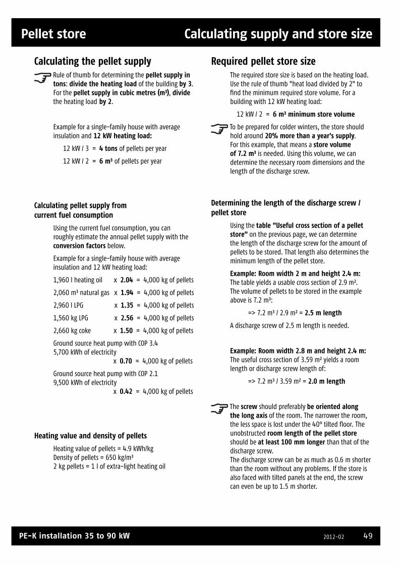
49PE-K installation 35 to 90 kW 2012-02
Pellet store Calculating supply and store size
Calculating supply and store size
Calculating the pellet supply Rule of thumb for determining the pellet supply in tons: divide the heating load of the building by 3. For the pellet supply in cubic metres (m³), divide the heating load by 2.
Example for a single-family house with average insulation and 12 kW heating load:
12 kW / 3 = 4 tons of pellets per year
12 kW / 2 = 6 m³ of pellets per year
Calculating pellet supply from current fuel consumption
Using the current fuel consumption, you can roughly estimate the annual pellet supply with the conversion factors below.
Example for a single-family house with average insulation and 12 kW heating load:
1,960 l heating oil x 2.04 = 4,000 kg of pellets
2,060 m³ natural gas x 1.94 = 4,000 kg of pellets
2,960 l LPG x 1.35 = 4,000 kg of pellets
1,560 kg LPG x 2.56 = 4,000 kg of pellets
2,660 kg coke x 1.50 = 4,000 kg of pellets
Ground source heat pump with COP 3.4 5,700 kWh of electricity x 0.70 = 4,000 kg of pellets
Ground source heat pump with COP 2.1 9,500 kWh of electricity x 0.42 = 4,000 kg of pellets
Heating value and density of pellets
Heating value of pellets = 4.9 kWh/kg Density of pellets = 650 kg/m³ 2 kg pellets = 1 l of extra-light heating oil
Required pellet store sizeThe required store size is based on the heating load. Use the rule of thumb "heat load divided by 2" to fi nd the minimum required store volume. For a building with 12 kW heating load:
12 kW / 2 = 6 m³ minimum store volume
To be prepared for colder winters, the store should hold around 20% more than a year's supply. For this example, that means a store volume of 7.2 m³ is needed. Using this volume, we can determine the necessary room dimensions and the length of the discharge screw.
Determining the length of the discharge screw / pellet store
Using the table "Useful cross section of a pellet store" on the previous page, we can determine the length of the discharge screw for the amount of pellets to be stored. That length also determines the minimum length of the pellet store.
Example: Room width 2 m and height 2.4 m: The table yields a usable cross section of 2.9 m². The volume of pellets to be stored in the example above is 7.2 m³:
=> 7.2 m³ / 2.9 m² = 2.5 m length
A discharge screw of 2.5 m length is needed.
Example: Room width 2.8 m and height 2.4 m: The useful cross section of 3.59 m² yields a room length or discharge screw length of:
=> 7.2 m³ / 3.59 m² = 2.0 m length
The screw should preferably be oriented along the long axis of the room. The narrower the room, the less space is lost under the 40° tilted fl oor. The unobstructed room length of the pellet store should be at least 100 mm longer than that of the discharge screw. The discharge screw can be as much as 0.6 m shorter than the room without any problems. If the store is also faced with tilted panels at the end, the screw can even be up to 1.5 m shorter.

50 www.eta.co.atSubject to change due to technical improvements
Filling nozzle, earthing, electricity Pellet store
Filling nozzle, earthing, electricity
Installing the fi lling nozzles in the short side of the pellet store
Two nozzles are installed 20 cm (mid-pipe) under the ceiling in the shorter wall (preferably) of the pellet store, one (centred) for blowing in the pellets and the other (to the side) for back air. Opposite the central nozzle, an impact protection sheet is installed to prevent damage to both pellets and the plasterwork on the opposite wall.
Discharge screw
Impact protection sheetNW 100 coupling nozzle(Storz type A fire hose coupling)
at lea
st 5
0 c
m
See detail drawing (doors)
50 cm
Only in exceptions in the longer wall
In exceptional cases, when the shorter walls of the pellet store are inaccessible from outside, the fi lling nozzles can be installed in the longer wall with one nozzle for each half of the room and an impact protection sheet across from each. The disadvantage is that halfway through the injection process, the hoses must be exchanged.
Discharge screw
Two impact protection sheets
NW 100 coupling nozzle(Storz type A fire hose coupling)
50 cm
41/ /41 41//41
Installing the fi lling nozzlesThe fi lling nozzles must be fi rmly anchored in the wall so they can withstand the movements of the hoses from the delivery vehicle and cannot rotate when the hoses are attached. They should be mounted horizontally 20 cm (mid-pipe) under the ceiling of the pellet store so that the pellets are not blown against the ceiling. To install the fi lling nozzles in smooth holes or sewer pipe cut-outs so they cannot twist, the ETA fi lling nozzles are equipped with a fl ange that transfers the forces directly into the wall via four plug screws. ETA fi lling nozzles with 108 mm diameter fi t exactly in the cut-outs made for fi tting a sewer pipe with 110 mm outside diameter. The small gap between nozzle and wall can be sealed with silicone; for larger gaps, foam is used.
20 cm
Connect nozzle with 6mm² to
house earth
Filling nozzles below ground level
If the fi lling nozzles are installed below ground in an area, ensure that the hose can be led out of the area in a straight line. If that is not possible using the connector with 45° bend, an additional 45° bend will be needed.
min. 60 cm
20 cm
The lever for tightening the coupling, around 30 cm long, needs a working range of 120°. If that much space is not available in the area, the nozzle must be extended over the edge of the area with a straight extension.

51PE-K installation 35 to 90 kW 2012-02
Pellet store Filling nozzle, earthing, electricity
min. 60 cm
20 cm
Earthing against electrostatic charge
Connect the fi lling nozzles to the earthing of the house's electrical system with a 6 mm² earthing cable.
Electrical socket for pellet supplier's blower
For the pellet supplier's suction blower, a 230V electrical socket (C-13A fuse) in the vicinity of the fi lling nozzle is useful.
CAUTION! Switch off the boiler before injecting pellets
The authorities or the chimney sweep often require that this notice be posted visibly on the fi lling nozzle's caps. Burn-back fl aps and sliders at the boiler's combustion chamber are open during operation, so during boiler operation, hot gases can be sucked into the path of the pellets (due to underpressure in the fuel deposit) or air can be blown through the fuel path (due to overpressure in the fuel deposit). Both effects can cause a fi re. Strictly speaking, the boiler should already be switched off two hours before fi lling the pellet store, because the burn-back fl aps and sliders do not always close completely. So there should be no more fi re in the boiler when fi lling pellets.
Better than a caution notice is a rotary valve
Since we at ETA don't want to leave the burn-back protection of our boilers to chance, we equip all ETA pellet boilers with a rotary valve so that even during operation there is no open connection between the combustion chamber and the pellet store. Though it is not required that an ETA pellet boiler be switched off while fi lling the pellet store, you should do so anyway if the driver of the delivery truck requests it.
Extension of the fi lling pipesThe ETA fi lling nozzles are made of steel, 108 x 3.2 mm, and can be extended with steel pipe if needed. If the tank truck can approach close to the fi lling nozzle so that its fi lling distance (30 m) is not already exceeded outside the building, then fi lling lines up to 20 m in length pose no problem. Height differences of one fl oor, or even two for short lines, can also be overcome without problems.
Extension with steel piping
• Only steel piping may be used for the filling system. Do not use plastic piping (danger due to electrostatic charge build-up).
• The filling system must be earthed against electrostatic charges.
• The filling system must be smooth on the inside throughout its length; do not use spiral ventilation ducting.
• If lengths of pipe are welded, there must be no welding seams or burrs inside; these could destroy the pellets.
• If bends are used, their radius of curvature should be at least five times the pipe's radius. As an alternative, you can make 90° bends by using two 45° bends with a straight piece between them.
• The filling system should end in a bend. To ensure that the pellets are blown out straight, a straight length of pipe at least 50 cm long must come after a bend.
Wooden boards
Door
Upper edge of tilted floor
Imp
act
pro
tect
ion
sh
eetFilling nozzle
20 cm below the ceiling and directed horizontally into the room
If possible, the door should be near the filling nozzle

52 www.eta.co.atSubject to change due to technical improvements
Dust-tight door, no cables/pipes Pellet store
Dust-tight door, no cables/pipes
Dust-tight, fi reproof T30 door
For pellet stores up to 6,500 kg there are no fi re safety demands in Germany on doors or other openings to the pellet store. Doors and other openings must open outward and be furnished with a circumferential dust-tight seal. For doors or other openings to the pellet store, wooden boards must be mounted on the inner wall (30 mm thick with tongue and groove) so the pellets cannot push against the door, or so that it can be opened. The door's lock must be sealed against dust on the inner side. In spite of a widely circulated construction document, the door handle on the inner side may not be removed. In an emergency, it must be possible to open the door from the inside.
Seal
Fireproof door T30 80/200 or 70/80
Boards at least 3 cm thick on the pellet store sideZ bracket
No cables/pipes in the pellet store
In the pellet store, there should be no water pipes or electrical cables. Water from a broken pipe would cause the pellets to swell up. Uninsulated electrical parts could ignite a dust explosion.
Shield cables/pipes that can't be removed, insulate cold water pipes to prevent condensation
Existing cold water pipes that can only be removed with unreasonable effort must be insulated against condensation to ensure that the pellets cannot be damaged by dripping condensation.
Pipes and cables in the path of pellets being injected, especially those on the ceiling, must be shielded. Ensure that the pellets are gently defl ected by a protective plate.
Flight path of pellets Protective plate
Piping/cabling to be protected
Flight path of pellets Protective plate
Piping/cabling to be protected
Only explosion-proof electrical installations
No electrical equipment such as switches, lights, junction boxes, etc. may be present in the pellet store. Unavoidable installations must be airtight and moisture-proof to protect against explosions, and in the fl ight path of pellets they must be protected against damage. Existing junction boxes that cannot be moved should at least be fi lled in with foam to seal all exposed live parts.

53PE-K installation 35 to 90 kW 2012-02
Pellet store Tilted floor
Tilted floor
Small stores with reserve
For small pellet stores, the tilted fl oor can be truncated. A reserve of pellets will remain on the resulting fl at surfaces; when the main store is empty, the reserve pellets can be swept into the
main store manually. This disadvantage of this method is that the reserve space must be cleared at least every 3 years so that dust and broken or moist pellets cannot gather.
Tilted fl oor
The pellet store must have a fl oor with 40° tilt to ensure that all pellets in the store can be used. This applies for both discharge screws and suction heads.
Construction of tilted fl oor for pellet store
For the tilted fl oor, three-ply concrete formwork panels 27 mm thick have proven effective. Unplaned wooden boards 25 mm thick with a smooth plastic-laminated surface can also be used.
The tilted fl oor should be fl ush with the enclosing walls so that no pellets can fall into the empty space. However, the support frame itself may not lean against the walls since they may not have the strength to resist the forces involved.
The tilted fl oor must withstand the weight of the pellets (bulk weight 650 kg/m³). Assuming the usual commercially available formwork panels with a width of 100 cm, members of the support frame should have a separation of 50 or 100 cm. For these separations, the adjacent tables show the required beam thicknesses depending on the room width.
Mount suction heads on a board
If the suction heads sit directly on a cold concrete fl oor, water from the circulating air can condense on the cold suction head. The condensation can cause pellets and, in particular, pellet dust to form clumps that can clog the pneumatic conveyor. To avoid this, always mount the suction heads on an insulated board (25/27 mm thick like the panelling).
Use padding when installing the screw channel in the wall opening (structure-borne noise)
Sound from the screw can be transmitted through the pellet store walls into the house. To avoid that, encase the screw channel with soft material (mineral wool) in the wall opening. Under no circumstances should the screw channel be cemented into a concrete wall without acoustic insulation.
Beams for support frame. beam separation 50 cmfor room height of 2.5 m
Cross section in cm Separation in m Room width in m
8 x 4 1.50 2.25
10 x 5 2.20 3.30
12 x 6 3.00 4.50
10 x 10 3.40 5.10
Beams for support frame, beam separation 100 cmfor room height of 2.5 m
Cross section in cm Separation in m Room width in m
10 x 5 1.50 2.25
12 x 6 2.00 3.00
10 x 10 2.20 3.30
15 x 5 2.35 3.50
appr
ox. 0
.2m
2 3 1 3
40°
at least 0.5 m
Support frame
Back air nozzle
320 x 250 mm wall opening
Filling nozzle (centred, 2 nozzles offset in rooms wider than 3m)
27 mm formwork panels (smooth surface)
Wooden beams
No transfer of forces from support frame to walls with insufficient strength
Separation

54 www.eta.co.atSubject to change due to technical improvements
Checklist
Checklist
Boiler installationMinimum wall clearances maintained (space for maintenance)Safety valve without shut-off on boiler outletExpansion tank with gross capacity 10% of system volume installed directly in boiler return, for buffer systems in return between boiler and bufferAir valve directly at boiler outlet and at highest point in systemWithout buffer, sufficiently large heat exchanger in the tank (0.8 m² for 10 kW, 1.5 m² up to 25 kW, 2.5 m² up to 50 kW, 4 m² up to 90 kW)Return temperature raising facility with pump or mixing valve dimensioned for minimum return temperature 60°C Safety heat exchanger with thermally actuated drain valve on water inlet and visible drain to sewerFilling and drain valve for each area that can be shut off individuallyPressure gaugeBoiler set up on sound insulation mat if output greater than 30 kW and positioned near living quartersEmergency stop switch always required in Austria, can be required by authorities in Germany above 50 kWBuffer storage tank if presentFor parallel connected buffers with 5/4" connections (values for 6/4" in parentheses): one-sided connection possible for two buffers up to 25 (40) kW, Tichelmann connection for two buffers up to 80 (130) kW, over 80 (130) kW external piping symmetrical or Tichelmann, external Tichelmann connection for more than two buffers in any caseSoftened water for initial fill-up: 20,000 lt°dH for system volume (in litres) multiplied by the hardness (in degrees of German hardness) may not be exceeded. Air valve on top of buffer storage tankSafety valve for buffers with solar chargingShut-off valves on all buffer connections (minimises drain volume - minimum lime content)Buffer sensors set so that the required supply volume is ensured for hot water or peak loads.Return temperature from system low enough to achieve the required storage capacity. Check radiator systems in particular to ensure that sufficiently adjustable radiator valves are installed. Throttle air heat exchangers to the amount of water actually neededChimneyChimney cross-section not too largeMulti-layered, insulated, moisture-resistant chimney or chimney renovation with inserted pipeCondensate drainage with siphon from chimney to sewerConnection pipe from boiler to chimney, short with few bends, thermally insulated, ascendingFlue pipe inserted into chimney sleeve with padded seal (structure-borne noise)Accessible cleaning apertures in chimney and flue pipe bendsFor boiler output 70 kW or more, a deflagration damper (blowback flap) is required in the connection pipe between the boiler and the chimney or in the chimney within the boiler roomDraught limiter for chimneys higher than 12 m above boiler room floor, set to 5 to 10 PaAir inlet and outletSufficient air inlets/outlets in Austria (ÖN H 5170): Air supply 2 cm² per kW of fuel thermal input, at least 200 cm² free cross-section, for up to 100 kW rated heat output, outlet at least 180 cm² free cross-section and for every additional kW another 1 cm², for wire screens at least 20% extra, for air flow through ducts longer than 1 m larger cross-sections and documented calculations by an expertSufficient ventilation in Germany (MFeuVO): up to 35 kW, door/window to the outside and room volume of 4 m³/kW, 35 to 50 kW at least 150 cm² free ventilation cross-section, over 50 kW at least 150 cm² free ventilation cross-section + 2 cm² per kW over 50 kW, for wire screens at least 20% extra, for air flow through ducts considerably larger cross-sections (50 to 150% larger -> calculate)Pellet store if presentThere may be no electric lamps, switches, sockets, junction boxes, etc. in the pellet store (danger of dust explosion); if unavoidable, then only using explosion-proof designsPiping that cannot be removed must be covered by deflector sheets slanted away from the incoming pelletsFilling nozzles easily accessible for pellet supplier and firmly installed in the masonryFilling and back air nozzles are earthedFilling nozzle is installed 20 cm beneath the ceiling (centre of pipe) and directed horizontally into the room (not towards the ceiling)Impact deflection sheet across from the filling nozzleTilted floor has a smooth surfaceDoors and other openings into storeroom sealed all around. Keyhole sealed on the insideWooden boards installed on inner side of doorEntire storeroom dust-tightPadded screw installation in wall opening (structure-borne noise)Floor and walls of storeroom are dry

55PE-K installation 35 to 90 kW 2012-02
Commissioning Dismantling, disposal
Dismantling
Dismantling is done in the reverse order of assembly.
Disposal
Disposal including all components must be done in an environmentally friendly manner according to waste disposal laws. Recyclable materials must be cleaned and separated before recycling.
Commissioning
Before commissioning the boiler, ensure that the entire heating system has been filled with enough water and has been purged of air.
The control system must be configured for the actual system. See the separate document "Control parameters".
Commissioning must be performed by the heating technician or another specialist.
Proper installation of all components and correct configuration and function of all control and safety mechanisms must be verified.
We recommend giving the operator a certification to this effect. In addition, the heating techni-cian must explain to the operator in detail the operation and maintenance of the boiler system including all peripheral equipment, especially the function of the safety-related equipment and the measures needed for continued safe operation.
Commissioning
Dismantling, disposal

56 www.eta.co.atSubject to change due to technical improvements

57PE-K installation 35 to 90 kW 2012-02

58 www.eta.co.atSubject to change due to technical improvements

59PE-K installation 35 to 90 kW 2012-02

60 www.eta.co.atSubject to change due to technical improvements
Safety instructions
PE-K
_Mon
tage
_Tou
ch_2
012-
02_E
N, su
bjec
t to
tech
nica
l alte
ratio
ns
Safety instructions
Prevent moisture from damaging pellets!
Danger! Moving parts may cause injuries!
Open door to pellet store, filling andventing nozzles for minimum 60 minutesventilation prior to entering storeage area!
Ensure that the ETA pellet boiler is inautomatic mode while store is being filled!Switch main power supply to OFFbefore entering the pellet storage area!
Smoking, naked flame or any otherignition sources are prohibited!
No entry for unauthorized personnel!Area unsafe for children!
www.eta.co.at
Wood Pellets - Storage Room
Only enter the pellet storeage area while inthe presence of a second person!The second person should remain outsidethe storage area in case of help is needed!
Related Documents


